Forum for Electromagnetic Research Methods and … A Low Loss Self-Packaged Quasi-Lumped-Element...
25
MC-5 A Low Loss Self-Packaged Quasi-Lumped-Element High Pass Filter Using SISL Technology Zonglin Ma, Kaixue . Ma, Fanyi Meng School of Physical Electronics, University of Electronic Science and Technology of China, China [email protected] Forum for Electromagnetic Research Methods and Application Technologies (FERMAT)
Transcript of Forum for Electromagnetic Research Methods and … A Low Loss Self-Packaged Quasi-Lumped-Element...

MC-5
A Low Loss Self-Packaged Quasi-Lumped-Element
High Pass Filter Using SISL Technology
Zonglin Ma, Kaixue. Ma, Fanyi Meng
School of Physical Electronics, University of Electronic
Science and Technology of China, China
Forum for Electromagnetic Research Methods and Application Technologies (FERMAT)

© The use of this work is restricted solely for academic purposes. The author of this work owns the copyright and no reproduction in any form is permitted without written permission by the authors.
Copyright

Prof. Kaixue Ma (M’05–SM’09) received his Ph.D degree from Nanyang TechnologicalUniv. (NTU), Singapore. From 1997 to 2002, he was with China Academy of SpaceTechnology (Xi’an), where he was Group Leader of millimeter-wave group for space-borne microwave & mm-wave circuits and systems. From 2005 to 2007, he was withMEDs Technologies as an R&D Manager. From 2007 to 2010, he was with STElectronics as R&D Manager and Technique Management Committee etc. From 2010to 2013, he was a Senior Research Fellow in NTU and mm-wave IC team leader for60GHz Flagship Chipset project. From 2013 till now, he is full professor in Universityof Electronic Science and Technology of China (UESTC). His research interests includeRFIC, mm-wave circuits and system using CMOS, MMIC etc. He filed 18 patents andauthored/co-authored more than 160 referable international journal and conferencepapers. He proposed SISL design Platform and received several awards including bestpaper award from IEEE SOCC2011, IEEK SOC Design Group Award etc. He receivedSpecial Mention Award of emerging Technology, Singapore Inforcomm TechnologyFederation 2012 and Named in precious China “Thousand Young Talent Program”2012 and in “The National Science Fund for Distinguished Young Scholars” 2016.
Biography

Abstract and Keywords
Abstract: This paper presents a low loss self-packaged quasi-lumped-element high pass filter (HPF) based on substrate integrated suspended line (SISL) technology. The HPF is composed of double metal layer spiral inductors and interdigital capacitors. And the dielectric loss for the filter elements is further reduced through hollowing the support substrate. The HPF also has advantages of self-packaging, low loss, compact size, and low cost by using SISL technology.
Keywords: Substrate integrated suspended line (SISL), spiral inductor, interdigital capacitor, dielectric loss

Outline
1 Motivation
2 SISL Platform
3 Quasi-Lumped-element
4 High pass filter
5 Measurement
6 Conclusion
Outline

Motivation
Motivation
High pass filters (HPF) are widelyused in microwave systems tosuppress the undesired spurioussignals in low frequency, and thequality of HPF directly affects theperformance of these systems.

SISL Technology
Substrate Integrated Suspended Line (SISL) Technology
(1) Five substrates are stacked up in order.(2) Substrate2 and substrate4 are hollowed to form two air cavities.

Advantages of SISL Technology
(1) Self-packaging
(2) Low Loss-Low Substrate Loss: electric field mainly distributed in the air Cavities.-Low Radiation Loss: due to the metallic walls.
(3) Multilayer
(4) Small Size
(5) Light Weight
(6) Low Cost
Electric field distribution
SISL Technology

Quasi-Lumped-Element
Quasi-Lumped-Element
Take advantages of multilayer of SISL technology, both lateral and vertical electronicfield are used.
Double Interdigital Capacitor

Compared with parallel-plate Capacitor
Double Interdigital capacitor has advantages of:(1) High capacitance density(2) High self-resonant frequency (SRF)(3) High quality factor (Q)
Quasi-Lumped-Element
“For a clear comparison, we choose one CIDC case with dimensions of Lc=4 mm, Sc=0.1 mm, Wc=0.3 mm,
n=10, as well as the single-layer interdigital capacitor and the parallel-plate capacitor, both with same dimensions
as that of CIDC in SISL. Simulated by HFSS, the capacitance of the CIDC is obtained as 2.75 pF, which is higher
than the traditional single-layer interdigital capacitor (1.85 pF) and the parallel-plate capacitor (1.68 pF).”

Compared with parallel-plate Capacitor
Quasi-Lumped-Element
To validate the simulated results, we have fabricated one case of the proposed CIDC with the dimensions of Wc=0.3 mm, Sc=0.2 mm, Lc=4 mm, n=10, and the actual network parameters of the CIDC is extracted by using the open-short de-embedding method [14], as shown in Fig. 4. The measured capacitance of this CIDC is 2 pF, which agrees with the simulated one of 2.07 pF.

Take advantages of multilayer and low loss of SISL technology, Double metal layersare used.
Spiral Inductor
Quasi-Lumped-Element

(Inductance of double layer inductor and single layer inductor both are 9.5nH )
Compared with single layer inductor
Interdigital layer spiral inductor has high quality factor (Q).
Inductance comparisonQ factor comparison
Quasi-Lumped-Element

Substrate hollowed
Dielectric loss can be further reduced by hollowing the support substrate.
Electric field distribution of SISL Electric field distribution of substrate hollowed SISL
Quasi-Lumped-Element

High Pass Filter
High Pass Filter
Considering the interdigital capacitor have lower self-resonant frequency than spiralinductor. In order to ensure the passband as wide as possible, structure1 is chosen inthis design
Structure1 Structure2
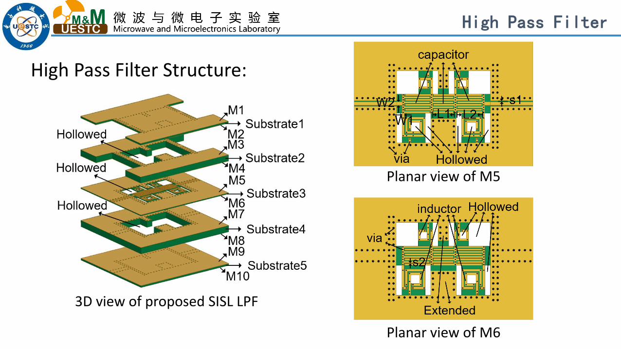
High Pass Filter Structure:
3D view of proposed SISL LPF
Planar view of M6
Planar view of M5
High Pass Filter

(1) The support substrate is hollowed to further reduce the dielectric loss.
(2) For the purpose of suppressing the resonant modes, there are two metallic walls extended at the middle of the cavity.
High Pass Filter
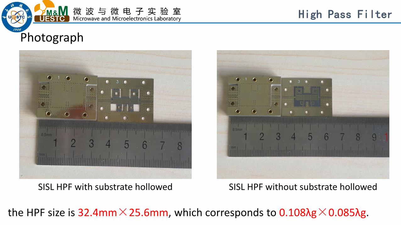
Photograph
SISL HPF with substrate hollowed SISL HPF without substrate hollowed
the HPF size is 32.4mm×25.6mm, which corresponds to 0.108λg×0.085λg.
High Pass Filter

Measurement
Insertion loss comparisonS Parameters
Measurement

(1) The minimum insertion loss in the passband is 0.1 dB.(2) Renturn loss is better than 20dB from 1GHz to 5GHz.(3) The method of substrate hollowed can further reduce
filter insertion loss 0.2dB.
Measurement

Our Other Works
Proposed Substrate Integrated Suspended Line (SISL)
Active, passive and system
Publicized 20 papers this area in IEEEE
Coupler
Designed
Circuits implemented on this platform:
Magic-T Filter
VCO Antenna
Photographs of the fabricated circuits
Balun
Core circuitry inside
SwitchPA
典型结构
Proposed,with USA and China patents, Sponsored by NSF project

Conclusion
Conclusion
(1) SISL technology has the advantages of self-packaging, low loss,multilayer, small size, light weight, low cost.
(2) Interdigital capacitor and double layer spiral inductor have manyadvantages.
(3) The method of substrate hollowed can further reduce filterinsertion loss.

Acknowledgment
This work was supported in part by the National Natural
Science Foundation of China under Grant 61471092, and in part
by Natural Science Foundation of China for Distinguished
Young Scholar under Grant 61625105.
Acknowledgment

References[1] W. Menzel and A. Balalem, "Quasi-lumped suspended stripline filters and diplexers," in IEEE Transactions onMicrowave Theory and Techniques, vol. 53, no. 10, pp. 3230-3237, Oct. 2005.[2] K. Ma and K. T. Chan, “Quasi-planar Circuits with Air Cavities” PCT Patent WO/2007/149046.[3] J.-S. Hong and M. J. Lancaster, Microstrip Filter for RF/Microwave Applications. New York, NY, USA: Wiley, 2001.[4] H. Samavati, A. Hajimiri, A. R. Shahani, G. N. Nasserbakht and T. H.Lee, "Fractal capacitors," in IEEE Journal ofSolid-State Circuits, vol.33, no. 12, pp. 2035-2041, Dec 1998.[5] L. Li, K. Ma and S. Mou, "De-embedding and modeling of spiral inductor based on substrate integratedsuspended line technology," 2016 IEEE MTT-S International Conference on Numerical Electromagnetic andMultiphysics Modeling and Optimization (NEMO), Beijing, 2016, pp. 1-2.[6] Y. Wang, K. Ma, N. Yan, L. Li, “A Slow Wave Rat-Race Coupler Using Substrate Integrated Suspended LineTechnology“, IEEE Transactions on Components, Packaging and Manufacturing Technology, vol. 7, No.4, pp 630-636,April. 2017[7] N. Yan, K. Ma, Y. Wang, L. Li “A Novel Substrate Integrated Suspended Line Quasi-Yagi Ultra-Wide Band Antenna”IEEE Transactions on Components, Packaging and Manufacturing Technology,vol. 6, No.8, pp1261~1267, 2016[8] L. Li, K. Ma, N. Yan, Y. Wang, S. Mou, “A Novel Transition from Substrate Integrated Suspended Line to ConductorBacked CPW”, IEEE microwave and wireless components lett. vol.26, No.6, pp389~391, June. 2016[9] Y. Wang, K. Ma, S. Mou, “A High Performance Tandem Coupler Using Substrate Integrated Suspended LineTechnology”, IEEE microwave and wireless components lett. vol.26, No.5, pp328~330, May. 2016[10] W. Yang, K. Ma, K.-S. Yeo, W. Lim “A Compact High-Performance Patch Antenna Array for 60-GHz Applications”,IEEE Antennas and Wireless Propagation Letters vol.15, pp313~316, 2016[11] Y. Wang, K. Ma, S. Mou, “A Compact Branch-Line Coupler Using Substrate Integrated Suspended lineTechnology”, IEEE microwave and wireless components lett. vol.26, No.2, pp92~95, February. 2016

Thank you!