Class Agenda Excel Formulas & Functions Logical Statements Charts (Graphs) Worksheet # 5.

FORMULAS AND CHARTS FOR IMPEDANCES OF
SURFACE AND EMBEDDED FOUNDATIONS
By George Gazetas , ' Member , ASCE
ABSTRACT: A complete set of algebraic formulas and dimensionless charts is presented for readily computing the dynamic stiffnesses (K) and damping coefficients (C) of foundations harmonically oscillating on/in a homogeneous half-space. All possible modes of vibration, a realistic range of Poisson's ratios, and a practically sufficient range of oscillation frequencies are considered. The foundations have a rigid basemat of any realistic solid geometric shape. The embedded foundations are prismatic, having a sidewall-soil contact surface of height d, which may be only a fraction of the embedment depth D. Two numerical examples illustrate the use of the formulas and charts and elucidate the role of foundation shape and degree of embedment on radiation damping for various modes of vibration. A companion paper (Gazetas and Stokoe 1991) presents supporting experimental evidence from model tests. The two papers aim at encouraging the practicing engineer to make use of results obtained with state-of-the-art formulations, when studying the dynamic response of foundations.
INTRODUCTION
A key step in current methods of dynamic analysis of soil-foundation-structure systems under seismic or machine-type inertial loading is to estimate, using analytical or numerical methods, the (dynamic) impedance functions associated with a rigid but massless foundation. In the last 20 years a number of techniques have been developed for computing and using foundation impedances; extensive reviews of these developments were presented by Lysmer (1978), Roessett (1980a, b), Luco (1982), Gazetas (1983), Novak (1987), and Pais and Kausel (1988). The presently available methods include: (1) Analytical solutions based on integral transform techniques; (2) semianalytical and boundary-element formulations requiring discretization of only the top surface; (3) dynamic finite-element methods using special "wave-transmitting" lateral boundaries; and (4) hybrid methods combining analytical and finite-element approaches.
In practical applications the selection of an appropriate method depends to a large extent on the size and economics of the project, as well as the availability of pertinent computer codes. Moreover, the method to be selected must adequately reflect the following key characteristics of the foundation-soil system and the excitation.
• The shape of the foundation-soil interface (circular, strip, rectangular, arbitrary).
• The amount of embedment (surface, partially or fully embedded foundation, piles).
'Dept. of Civ. Engrg., 212 Ketter Hall, State Univ. of New York, Buffalo, NY 14260.
Note. Discussion open until February 1, 1992. Separate discussions should be submitted for the individual papers in this symposium. To extend the closing date one month, a written request must be filed with the ASCE Manager of Journals. The manuscript for this paper was submitted for review and possible publication on May 14, 1990. This paper is part of the Journal of Geotechnical Engineering, Vol. 117, No. 9, September, 1991. ©ASCE, ISSN 0733-941O/91/0O09-1363/$l.O0 + $.15 per page. Paper No. 26172.
1363

• The nature of the soil profile (deep uniform or layered deposit, shallow stratum over bedrock).
• The mode of vibration and the frequency(ies) of excitation.
Application of computational methods to a specific engineering problem requires substantial expertise in idealizing the actual system, and entails significant data-preparation and computation expenses. Thus, the effort needed to obtain one or two sets of usable results may preclude parameter studies— much needed for evaluating alternative design schemes and clarifying the role of uncertainties in material properties. Furthermore, the effects of some potentially significant phenomena (such as separation/sliding at the soil-foundation contact surface) or of geometric complexities (as in the case of foundations with arbitrary shape and partial contact along the perimeter) cannot be modeled readily with existing computer codes.
As a practical alternative, several researchers have over the years developed simplified methods, presented results in dimensionless graphical or tabular form, or fitted simple equations to their numerical results [examples: Lysmer and Richart (1966), Whitman and Richart (1967), Beredugo and Novak (1972), Meek and Veletsos (1973), Veletsos and Nair (1974), Kausel and Roesset (1975), Elasabee and Morray (1977), Novak et al. (1978), Kausel and Ushijima (1979), Roesset (1980), Kagawa and Kraft (1980), Velez et al. (1983), Gazetas (1983, 1987), Wong and Luco (1985), Pais and Kausel (1988), Gazetas et al. (1985), Hatzikonstantinou et al. (1989), Fotopou-lou et al. (1989), Wolf (1988), Mita and Luco (1989)].
This paper presents a complete set of simple formulas and graphs covering (1) Nearly all foundation base shapes (excluding annular); (2) surface and partially and fully embedded foundations; (3) all the significant modes of vibration and a fairly adequate frequency range; but (4) only reasonably deep and uniform soil deposits that can be modeled as a homogeneous half-space. The latter choice is made out of necessity: a homogeneous half-space is the only idealization for which a complete set of results could be found or easily obtained, and that keeps the number of problem parameters to a minimum while the engineer tries to quantify the role of partial embedment and of basemat shape. Actually, however, the deposit need not be very deep for the half-space idealization to be applicable: horizontal and, especially, rotational oscillations are known to produce very shallow dynamic pressure bulbs (on the order of one foundation width or even less).
PROBLEM STATEMENT; DEFINITION OF IMPEDANCES
The geometry of the rigid but massless foundations addressed in this paper is sketched in Fig. 1(a) (surface foundation) and in Fig. 1(b) (embedded foundation). The steady-state response of such systems to harmonic external forces and moments can be computed with well-established methods of structural dynamics once the matrix of dynamic impedance functions [S(co)] has been determined for the frequency (ies) of interest.
For each particular harmonic excitation, the dynamic impedance is defined as the ratio between force (or moment) R and the resulting steady-state displacement (or rotation) U at the centroid of the base of the massless foundation. For example, the vertical impedance is defined by
1364

(b)
Massless rigid foundation
T * " y ~
•- • D
H o m o g e n e o u s H a l f s p a c e
' . ' - G ' ^ ?> P '.• •
Sidewalt may be in effective contact with soil only over part of its height
d j im::.--[••.:•
» ^ . ' i
H o m o g e n e o u s H a l f s p a c e . " ' • ' • . ' • '
'. ::':':0 . V . p . f! • : • " . • . ' . ' • • . ; ' . :"\- :.•;
FIG. 1. (a) Surface Foundation of Arbitrary Shape (See Table 1 and Fig. 2); (b) Embedded Foundation of Arbitrary Basemat Shape (See Table 2 and Fig. 3)
S,= mo Uz(0
(1)
in which Rz(0 = R2 exp («W) = harmonic vertical force; and Uz(f) = U2 exp (imt) = harmonic vertical displacement of the soil-foundation interface. The quantity R2 is the total dynamic soil reaction against the foundation; it is made up of normal tractions against the basemat plus shear tractions along any vertical sidewalls.
Similarly, the following impedances are defined: Sy = lateral swaying impedance (force-displacement ratio), for horizontal motion in the short direction; Sx = longitudinal swaing impedance (force-displacement ratio), for horizontal motion in the long direction; S„ = rocking impedance (moment-rotation ratio), for rotational motion about the long centroidal axis (x) of the foundation basemat; S , = rocking impedance (moment-rotation ratio), for rotational motion about the short centroidal axis (y) of the foundation base-mat; and S, = torsional impedance (moment-rotation ratio), for rotational oscillation about the vertical axis (z).
Moreover, mainly in embedded foundations and piles, horizontal forces along principal axes induce rotational (in addition to translational) oscillations; hence, two more "cross-coupling" horizontal-rocking impedances exist: S - , and Sy-„. They are negligibly small in surface and shallow foundations, but their effects may become appreciable for greater depths of embedment owing to the moments about the base axes produced by horizontal soil reactions against the sidewalls. In piles, such cross-coupling impedances are as important as the "direct" impedances.
1365

Note that throughout this paper (as in most of the literature) all impedances refer to axes passing through the centroid of the foundation basemat-soil interface.
Because of the presence of radiation and material damping in the system for all modes of vibration, R is generally out of phase with U. It has become traditional to introduce complex notation and to express each impedance in the form
S = K + mC (2)
in which both K and C = functions of the frequency a>. The real component, K, termed "dynamic stiffness," reflects the stiffness and inertia of the supporting soil; its dependence on frequency is attributed solely to the influence that frequency exerts on inertia, since soil properties are practically frequency independent. The imaginary component, o>C, is the product of the (circular) frequency w times the "dashpot coefficient," C; the latter reflects the radiation and material damping generated in the system (due to energy carried by waves spreading away from the foundation and energy dissipated in the soil by hysteretic action, respectively).
Eq. (2) suggests for each mode of oscillation an analogy between the actual foundation-soil system and the system that consists of the same foundation, but is supported on a "spring" and "dashpot" with characteristic moduli equal to K and C, respectively.
FORMULAS AND CHARTS
Tables 1 and 2, accompanied by Figs. 2 and 3, contain all the information needed to estimate for each of the aforementioned eight modes of vibration.
Table 1 and Fig. 2 contain the dynamic stiffnesses ("springs"), K = K((x>), each as a product of the static stiffness, K, times the dynamic stiffness coefficient k = /c(w)
K(u>) = K-&((0) (3)
And Table 2 and Fig. 3 contain the radiation damping ("dashpot") coefficients, C = C(w). These coefficients do not include the soil hysteretic damping, 3; to incorporate such damping, one simply adds the corresponding material dashpot constant 2/fp/co to the foregoing (radiation) C value
IK total C = radiation C + — p (4)
(0
While many of the algebraic expressions and the associated graphs given in Tables 1 and 2 were compiled from previous publications by the writer and his coworkers (Gazetas et al. 1985, 1987; Dobry et al. 1985; Hatzikonstan-tinou et al. 1989; and Fotopoulou et al. 1989), some additional results obtained for this article using two different boundary-element formulations, and retrieved from recent literature (Pais and Kausel 1988; Wolf 1988; Mita and Luco 1989; Ahmad et al. 1990) are also used. Note in particular that for torsion (of both surface and embedded foundations) completely new formulas were developed based on the results of a comprehensive boundary-element study by Ahmad et al. (1991). Moreover, some corrections were made and certain simplifications introduced in the results published previ-
1366

TA
BL
E
1.
Dyn
amic
Sti
ffn
esse
s an
d D
ash
po
t C
oef
ficie
nts
fo
r A
rbit
rari
ly S
hap
ed F
ou
nd
atio
ns
on
Su
rfac
e of
Ho
mo
gen
eou
s H
alf-
Sp
ace
Vib
ratio
n m
ode
(1)
Ver
tica
l (z
)
Hor
izon
tal
(y)
(lat
eral
dir
ecti
on)
Hor
izon
tal
(x)
(lon
gitu
dina
l di
rect
ion)
R
ocki
ng (
rx)
(abo
ut t
he
long
itud
inal
, or
-axi
s)
Roc
king
(ry
) (a
bout
the
la
tera
l, >>
-axi
s)
Tor
sion
(r)
Stat
ic s
tiffn
ess,
K
(2)
K,
=
[2G
L/(
1 -
v)](
0.73
+
1.54
x°75
) w
ith
X
=
Ab/
4L2
Ky
= [
2GL
/(2
- v)
](2
+
2.50
x08
5)
Kx
= K
y-
[0.2
/(0.
75
- v)
]GL
[l
- (f
i/L
)]
K„
= [
G/(
l -
v)]/
L75
(L/B
)025[2
.4 +
0.
5(B
/L)]
K„
=
[3G
/(1
- vW
l"(L
/B)°
15
K,
=
3.5G
I°bz
JS(B
/Lf(
,h!/B
i f2
Dyn
amic
stif
fnes
s co
effic
ient
, k
(0
SO
.S
2)
(3)
k 2 =
/t
z(L
/B,v
;ao)
is
plot
ted
in F
ig.
2(a)
k, =
ky
iL/B
;^)
is p
lott
ed i
n F
ig.
2(b)
K =
1
k„ s
1
- 0.
20ao
v <
0.
40:
i,
sl
- 0.
26a„
v
s 0.
50:
K,
=
1 -
0.26
ao(L
/B)03
0
k, =
1 -
0.
14oo
Rad
iatio
n da
shpo
t co
effic
ient
, C
(4
)
Cz
= (
pV^A
,,) •
c;
whe
re
c z =
c,
(L/B
;ao)
is
pl
otte
d in
Fig
. 2(
c)
C,
=
(pV
sAfc)
• c y
whe
re c
y
=
c,.(
L/B
;ao)
is
plot
ted
in F
ig.
2(d)
C,
= p
V,A
>
C„
=
(pV
io/ fa
) •
c„ w
here
c„
=
c„(L
/B;a
0)
is
plot
ted
in F
ig.
2(e)
C
„ =
(p
V^/
,, y)
• c„
whe
re
c„ =
c„,
(L/B
;oo)
is
plot
ted
in F
ig.
2(f)
C
, =
(pV
J b.)
•
c, w
here
c,
=
c,(L
/B;a
o) i
s pl
otte
d in
Fig
. 2(
g)
TA
BL
E 2
. D
ynam
ic S
tiff
nes
s an
d D
amp
ing
of
Fo
un
dat
ion
s E
mb
edd
ed i
n H
alf-
Sp
ace
wit
h A
rbit
rary
Bas
emat
Sh
ape
Vib
rati
on
mod
e (1
)
Ver
tica
l (z
)
Hor
izon
tal
(y)
and
(x)
Roc
king
(rx
) an
d (.
ry)
Sw
ayin
g-ro
ckin
g (x
-ry)
(y-r
x)
Tor
sion
(t
)
Stat
ic s
tiffn
ess,
*r cn
, b (2
)
* 2.™
b =
KJi
l +
(1/
21)(
D/B
)(1
+
1.3x
)][l
+
0.
2(A
W/A
bf»]
w
here
Kz
= A
Tj, so
rface
is
obta
ined
fro
m T
able
1.
Aw
=
actu
al s
idew
all-
soil
con
tact
are
a; f
or c
onst
ant
effe
ctiv
e-co
ntac
t he
ight
, d,
alo
ng t
he p
erim
eter
: A
w
= (
d) X
(p
erim
eter
); x
=
Ab/
4L2
Ky.
<«*
= K
ytt
+ 0
.15(
D/B
)°-5]{
1 +
0.
52[(
/t/B
)(A
„/L
2)]0'4}
^.™
b =
Kx
• (K
yjnt
b/K
y) w
here
Ky
= K
y^^c
an
d K
x =
-
.surfa
ce a
rc o
btai
ned
from
Tab
le 1
.
Krc
**
= K
„{1
+
1.26
(d/B
)[l
+
(d/B
)(d/
D)-
°2(B/L
f5]}
K^
= K
M
+ 0
.92(
d/L
f6[l.5
+
(d
/Ly^
d/L
)-"6]}
w
here
K„
=
K„
s„r
fa«
and
K„
= K
^ su
rfl„
are
obt
aine
d fr
om
Tab
le 1
.
Kx.r
y,,e
mb
—
(1/3
)£^
,cm
b K
y-rx
,cm
b —
(l
/3)^
v,c
mb
^i.e
mb
=
K,-
Tw •
rm
w
here
K,
= K
usah
^ is
obt
aine
d fr
om
Tab
le 1
. r„
=
1
+
OA
(D/d
f\jJ
j r)(B
/Df*
r
„ =
1
+
0.5(
D/B
)0•1
(B7/
fe)0
,3
j, =
(4
/3)d
(B3 +
L3 )
+ 4
BL
d(L
+
B
) j r
= (
4/3)
BL
(B2 +
L
2)
Dyn
amic
stif
fnes
s co
effic
ient
, h^
ita)
(3
)
(v =
= 0
.40)
: fu
lly
embe
dded
: K
*a,
** W
-
0.09
(D/B
)3/4a§
] in
a t
renc
h: *
,,«
s kj
il
+
0.09
(D/B
)V*4
) (v
=
0.48
):
fully
em
bedd
ed w
ith
L/B
=
1
-2
: *«
•* =
*,
[1 -
0.
09(Z
>/B
)3/4^]
fu
lly e
mbe
dded
wit
h L
/B
>
3:
*=. m
b =
*
,[!
- 0.
35(D
/B)1/
2<4'
5] in
a t
renc
h:
A^„
as
k z,
whe
re *
i =
fc,
, sllr
f
from
Tab
le 1
. A
ll v
, pa
rtia
lly
embe
dded
: in
terp
olat
e ky
iIm
b an
d t,
,„* c
an
be e
stim
ated
in
term
s of
L/
B,
D/B
, an
d d/
B
for
each
val
ue o
f Oo
fr
om t
he p
lots
in
Fig
. 3
*-w
,em
b =
=
NT
"ry.
emb
—
"ry
The
sur
face
-fou
ndat
ion
k n
and
£„ a
re
obta
ined
fro
m T
able
1.
kx-r
y,cm
b =
=
*y-7
*,ei
nb
==
t
*"f,e
mb
=
*r,s
urfa
ce
Rad
iati
on d
ashp
ot c
oeff
icie
nt,
C^
u)
(4)
C,^
=
C
2 +
pV
,A„
whe
re C
, =
C:, s
ulfa
« is
obt
aine
d fr
om T
able
1
and
the
asso
ciat
ed c
hart
of
Fig
. 2
.
Cy, O
Tb =
C
y +
4p
VJB
d +
4
?^
/^
C«„
b =
C
, +
A
pV^B
d +
4p
VsL
rf
whe
re C
y =
CJi
Sllr
facc
and
C,
=
CX
wm
tm
are
obta
ined
fro
m T
able
1 a
nd t
he
asso
ciat
ed c
hart
of
Fig
. 2.
C
„,m
b =
C
„ +
p/
fa(d
/B){
V^(
d2/B
2)
+
3VS
+
VS(B
/L)[
1 +
(d
2/B2)]
}-T
, r w
here
T)„
=
0.25
+
0.
65
V<
h (d
/D)-
°°/2
(£)/
B)-
'/4
Cry
,™*
's su
nil
arly
eva
luat
ed f
rom
C^
afte
r re
plac
ing
* by
y,
and
inte
rcha
ngin
g B
w
ith
L i
n th
e fo
rego
ing
two
expr
essi
ons.
In
both
cas
es %
— w
B/V
V
Cj-ry
.cmb
=
(1/3
)dC
„„, b
Cy-
„,c
^, =
(l/
3)dC
v,„
„ b
C, m
b =
C
, +
4
pd
[(l/
3)V
i,(L
3 +
B3)
+
VSB
£(L
+ B
)] •
T,„
whe
re C
, =
C,. s
ur&
x
is o
btai
ned
from
Tab
le 1
and
Fig
. 2
• n,=
(d
/D)-
05-4
/[a
o +
(l
/2)(
£/B
)-'5
]

FIG. 2. Dimensionless Graphs for Determining Dynamic Stiffness and Damping Coefficients of Surface Foundations (Accompanying Table 1)
ously to make the use of the presented information as simple and consistent as possible in engineering applications.
USE OF TABLES—ILLUSTRATIVE EXAMPLES
Surface Foundation on Half-Space For a nonrectangular basemat shape, the engineer must first draw a cir
cumscribed rectangle of width 2B and length 2L (L > B), as is done in Figs. 1, 4, and 5. [See Gazetas et al. (1985) for some additional examples.] Note that the results are not sensitive to the exact circumscribed rectangle, and that any reasonable such rectangle will suffice. Then, to compute from Table 1 the impedances in the six modes of vibration, all he needs is the values of the following.
• Ab = area; and Ibx, 1^, and lbz = area moments of inertia about the x-, y-, and z-axes of the actual soil-foundation contact surface. If loss of contact under part of the foundation (e.g. along the edges of a rocking foundation) is likely, the engineer may use his judgment to discount the contribution of this part of the basemat.
• B and L = half-width and half-length of the circumscribed rectangle. • G and v, the shear modulus and Poisson's ratio; or Vs and VLa, the shear-
wave velocity and Lysmer's analog wave velocity; the latter is the apparent propagation velocity of compression-extension waves under a foundation, related to V, and v according to (Gazetas et al. 1985; Dobry and Gazetas 1986)
1369
ii "W^— fZZ——
L/B= 6 0/ a
0
( f ) o
UBi6
D / B
^
kld/D) k[d/0=l)
( g ) n
o] •fe
^
. . A
,
e» ^
, ,
1
'y
0
1
a)
' - < -
L/B
)
D / B
o
\ \ '-< \
\ \
1 2
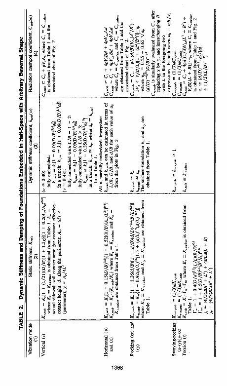
FIG. 3. DImenslonless Graphs for Determining Dynamic Stiffness Coefficients of Fully and Partially Embedded Foundations (Accompanying Table 2)
VLa = 3.4
TT(1 - v) (5)
• to = 2TT/ = circular frequency (in radians/second) of the applied force (e.g. frequency of operation of the machine or one of the dominant frequencies in the case of seismic excitation).
A numerical example illustrates the use of Table 1 and the related di-mensionless graphs of Fig. 2 in computing the dynamic stiffnesses (springs) and damping coefficients (dashpots), for the six significant modes of vibra-
1370

PLAN
M
CENTROID OF ACTUAL BASEMAT
oivoumeoribed rectangle
SECTION S
A L 0 S 0 X
(b)
I homogeneous halfspaae | a = ISO MPa i P - 1.8S Mg/m'
J V - 0.40
B « O.Ob
r%
•'••'•• r
(c)
FIG. 4. Geometry and Material Parameters of Two Illustrative Examples
tion. A sketch of the foundation with a list of all pertinent geometric, material, and loading parameters is given in Fig. 4. The excitation frequency i s / = 18 Hz, resulting in a dimensionless frequency factor a0 = wfi/V^ = 1.23. Due to lack of symmetry about the centroidal axis v, some "parasitic" cross-coupling modes may also get excited. For instance, a vertical external force acting through the centroid will be resisted by normal tractions against the basemat; the lack of complete symmetry in these tractions will trigger a rotational oscillation about the y-axis. Similarly a horizontal force parallel to y will trigger incidental torsional oscillations, and so on. Such secondary modes are not considered in this paper. The computations follow in metric (SI) units. Noting that x = Ab/4L2 = 0.26; and L/B = 3.2 we obtain the following.
Vertical Mode (Table 1, Column 1) Static stiffness (from formula of Table 1, column 2)
1371

1 l y 1
(a)
I —JjL B
Plans
UB=1
(c)
' r y
9\Jby
(d)
(b) L/8=2
Section Along y
IT — y
+T^r7+ . I-• i : i •
• z
V = 0.40
0 = B
O Boundary Element
™ Expression of table II
^ t l « *
a 0 = W B / V S
FIG. 5. Comparison between Rocking Dashpot C„ Functions Computed with Expression of Table 2 and Results of Rigorous (Boundary-Element) Solution for Two T-Shaped Foundations Embedded In Homogeneous Half Space
K = 2 x 120,000 x 8.0
X [0.73 + 1.54(0.26)a75] (6a) 1 - 0.40
Kz « 4.13 X 10⁶ kN/m (6b)
Dynamic stiffness coefficient (from Fig. 2 for a0 = 1.23) kz « 0.92. Dynamic stiffness (spring constant) from (3)
Kz = 4.13 X 106 x 0.92 = 3.8 x 10⁶ kN/m (7)
1372

Radiation damping (from formula of Table 1, column 4)
Cz = (1.85 x 460 x 66.82) x 1.0 « 56.9 x lO'kN-s-m""1 (8)
Total damping (dashpot constant) from (4)
2 X 3 8 X 10^ total C2 = 56.9 x 10³ + : x 0.05 = 60 X 103 kN • s • m"1 (9)
125.7
Lateral and Longitudinal Horizontal Modes (Table 1, Column 1)
Working in similar fashion we obtain the following.
Ky « 3.9 x 10⁶ kN/m (10)
Kx = 3.0 x 10⁶ kN/m (11)
total Cy « 34.5 x 10³ kN • s • m - 1 (12)
total C, « 34 x 103 kN • s • m - 1 (13)
Rocking Modes rx (Longitudinal Axis) and ry (Lateral Axis)
120,000 „ „ „ „ / 0.5\ Krx = x (121.1)075 x (3.2)025 x 2.4 + — (14a)
1 - 0.40 V 3.2/
Krx « 25 X 106 kN • m (14b)
krx « 1 - 0.20 X 1.23 « 0.754 (15)
Krx = 25 X 106 X 0.754 « 18.89 x 10⁶ kN • m (16)
Crx = (1.85 x 460 x 121.1) x 0.42 « 43.2 x 10 3 kN-s-m (17)
, 2 x 18.8 x 106
total Crx = 43.2 X 10³ + x 0.05
125.7
« 58 x 103 kN • s • m (18)
Working in similar fashion for mode ry
^ = 86.3 X 10⁶kN-m (19)
total C^ » 802 X 103 kN • m • s (20) Torsional Mode (Table 1, Column 1)
075 /1,226\° '2 /2 .5 \° ' 4
K, = 3.5 x 120,000 x (1,226)075 x I - \ x — I (21a)
K, « 109.0 X 10⁶ kN • m (lib)
k, « 1 - 0.14 x 1.23 * 0.83 (22)
K, = 109.0 x 106 x 0.83 « 90 x 106 kN • m (23)
C, = (1.85 x 255 x 1,226) x 0.88 (24a)
C, « 509 x 103 kN • m • s (24A)
1373

, 2 x 90 x 106
total C, « 509 x 103 + x 0.05 (25a) 125.7
total C, « 580 x 103 kN • m • s (25b)
This concludes the example computations. Having obtained for each mode the spring (K) and dashpot (tot-C) constants, the engineer can obtain the response of his structure or foundation using well-established methods of rigid-body or structural dynamics [e.g. Richart et al. (1970), Clough and Penzien (1974), Bielak (1975), Veletsos (1977), Arya et al. (1979), Roesset (1980b), Luco (1982), Gazetas (1983), Moore (1985), Das (1988), Prakash and Puri (1988)]. The companion paper (Gazetas and Stokoe 1991) outlines the use of K's and C's in determining natural frequencies and modal damping ratios of a freely oscillating rigid foundation.
To get an insight into the meaning of the computed C, values (J = z, y, x, rx, ry, t), let us consider that the foundation base of Fig. 4(a) supports a rigid block having a (total) mass m = 1,400 Mg; and (total) mass moments of inertia Jx = 12,000 Mg-m 2 ; Jy = 1,110,000 Mg-m 2 ; and Jz = 96,000 Mg • m2 about the base x- and y-axes, and the vertical z-axis, respectively. For each mode (assumed to be independent of the others) an "effective" or "equivalent" damping ratio, §, can be defined as follows.
Translational modes
total C, & = -~L (j = z,y,z) (26a)
2 y/Kjm
Rotational modes
totalC, it = —— (i = rx, ry, t; p = x,y, z) (26b)
2 VKJe [Notice in Figs. 2 and 3 that dynamic stiffnesses may attain negative values at certain frequency ranges. Such values imply a phase difference of 180°. The absolute value of such stiffnesses should be used in (20a) and (20ft)].
For the six modes considered we obtain the following.
• Vertical: & « 0.41, or 41%. • Lateral: l-y ~ 0.23, or 21%. • Longitudinal: ^ = 0.25, or 23%. • Rocking about x: £„ *= 0.06, or 6%. • Rocking about y: ^ ~ 0.13, or 13%. • Torsion: ij, » 0.10, or 10%.
From these values it is evident that with rotational modes the effective damping ratio is quite low; and with translational modes it can be very high— especially in the vertical direction. These differences are a direct consequence of different amounts of radiation damping, which results from geometric spreading of waves generated at the foundation-soil interface. When the foundation undergoes a vertical oscillation, such waves are emitted in phase and "reach" long distances away from the foundation; hence relatively large amounts of wave energy are "lost" for the foundation—high radiation damping. In contrast, two "points" symmetrically located on the opposite
1374

1.0-r-
0.7 ••
0.1 • •
g o. , .
0 . 1 ••
E °-°7--° 0 .04- -
0.02 • •
INERTIA RATIOS
FIG. 6. Radiation Damping Ratios of Circular Footing on Homogeneous Half-Space [after Richart et al. (1970)]
sides of a rocking foundation send off waves that are 180° out of phase and tend to cancel each other out when they meet at distant locations along the center line (dynamic equivalent of St. Venant's principle); hence, they cannot reach long distances and consequently dissipate little energy from that imparted onto the foundation—low radiation damping.
Such differences in effective damping ratios are typical for surface foundations on a homogeneous half-space. Fig. 6, adopted from Richart et al. (1970), refers to a circular foundatigon of radius R. Each of the four damping ratios, £r, £,, £,rx, and £„ is portrayed as a decreasing function of a corresponding mass or mass-moment of inertia ratio. The overall consistency of the damping ratios computed in this example with those anticipated from Fig. 6 is evident.
Two important conclusions emerge from Fig. 6. First, the consequences of resonance (when the operational or excitation
frequency coincides with the natural frequency of the foundation-soil system) are far more serious for rocking than for translational vibrations. Avoiding resonance in rocking is a prudent consideration. On the other hand, relatively light foundations vibrating vertically on a homogeneous half-space may experience damping in excess of 50%. Hence, occurrence of resonance would hardly spell disaster; avoiding resonance at any cost, as some older design procedures recommend, could be misleading. [Recall that the "dynamic amplification^" at resonance is inversely proportional to the product of £ V(l - |2).]
Second, the inertia of a foundation block increases relative to its base dimensions (i.e. as the inertia ratios increase) the effective damping ratios decrease. Therefore, older machine foundation design practices of keeping the foundation mass quite large are rather unfortunate. Another conclusion
1375

from Fig. 6 is that block foundations may not necessarily be sensitive to high-frequency excitation; because, even in the unlikely event of resonance, peak response may not be excessive: high natural frequencies would require relatively small masses or moments of inertia and would thereby be associated with high damping ratios. As a general rule, the critical frequency factors, a0 = uB/Vs, of interest do not exceed 2.
The foregoing conclusions are valid for surface foundations on sufficiently deep and homogeneous deposits (half-space). One of the important factors that may modify these conclusions (qualitatively and quantitatively) is the presence of embedment.
Foundation Embedded in Half-Space With the formulas and charts of Table 2 one can assess the effects of
embedment in a variety of realistic situations. Note that Table 2 compares the dynamic stiffnesses and dashpot coefficients of an embedded foundation, Kemb (= Kemb • kemb) and Cemb, respectively, with those of the corresponding surface foundation, K (= K-k) and C, obtained from Table 1 and its accompanying graphs (Fig. 2). The additional parameters that must be known or computed before using Table 2 are: (1) D = depth of the foundation base below the ground surface; and (2) Aw and d = total area of the actual side-wall-soil contact surface, and the height of the sidewall that is in good contact with the surrounding soil. The quantity A„ should, in general, be smaller than the nominal area of contact (and d smaller than the nominal wall height) to account for such phenomena as slippage and separation that may occur near the ground surface. The engineer should refer to published results of large- and small-scale experiments for a guidance in selecting a suitable value for Aw or d [e.g., Stokoe and Richart (1974), Erden (1974), Novak (1985), Crouse et al. (1990)]. Note that Aw or d may not necessarily attain a single value for all modes of oscillation.
A numerical example illustrates the use of Table 2 and Fig. 3. Fig. 4(b) sketches the foundation, whose basemat is identical to the mat of the previous example [Fig. 4(a)] but which is now placed at a depth D = 6 m. The sidewalls are in contact with the soil throughout the height D, but the engineer believes that the quality of contact at the top 2 m will be poor. He thus decides that the effective height of sidewall-soil contact is d = 4 m. The computations that follow make use of the results of the previous example for K and C of the surface foundation. However, only three of the modes are considered herein.
Vertical Mode (Table 2, Column 1) Noting that
Aw = 35.77 x 4.0 = 153 m2 (27)
D 6 - = — = 2.4 (28) B 2.5
and
A„ 153 — = = 2.14 (29) A„ 66.8
one obtains the following.
1376

Static stiffness (from the formula of Table 2, column 2)
K, = 4.13 x 106 x 2.4
1 + — (1 + 1.33 x 0.26) 21
x [1 + 0.2(2.14)2/J] « 4.13 x 10" x 1.33 « 5.5 x 10" kN/m (30)
The dynamic stiffness coefficient is obtained (with the help of Table 2, column 3) by linear interpolation between the fully embedded value of
**,d=D=6n, « 0.92[1 - 0.09(2.4)3/4(1.23)2] « 0.74 (31a)
and the value for the foundation placed in an open trench, without sidewalls, which is
kz^0 « 0.92[1 + 0.09(2.4)3/4(1.23)2] - 1.26 .
Thus
4.0 x 0.74 + 2.0 X 1.26
and
6.0 - 0 . 9 1
(31ft)
(31c)
K. 2,emb = 5.5 x 106 x 0.91 « 5.0 x 10⁶ kN/m (32)
Radiation and total damping [from formula of Table 2 and (4)]
C2,emb = 56.9 X 10³ + (1,185 x 255 x 143) « 124 X 103 kN • s • m"1 . . . (33)
2 x / x 106
total Cz emb = 124 X 103 + : x 0.05 (34a) 125.7
total Cz,emb « 128 x 103 kN • s • m"1 (34*)
Lateral Horizontal Mode (Table 2, Column 1) Noting that h = 4 m; h/B = 4 /2 .5 = 1.6; and Aw/L2 = 143/82 = 2.23,
one obtains the following.
Ky,cmb = 3.4 x 106 x (1 + 0.15 V2A)[l + 0.52(1.6 x 2.23)04].
y,emb « 3.4 x 1Q6 x 2.3 - 7.9 x 10⁶ kN/m.
(35a)
(35b)
For the dynamic stiffness coefficient, we use the graphs of Fig. 3 as follows: For fully embedded foundation d = D, interpolation between the plots for L/B = 2; and L/b = 6 yields
ky,d=D=bm ~ 0.30
and from the last chart of Fig. 3 [Fig. 3(g)]
(36)
'S'.ei Ky,d=D=6m
d 2 Jfc - = -
\D 3
"Td k - = 1
\D
0.30 x 1.25 x 0.38 (37)
1377

TABLE 3. Comparison between Stiffness and Damping of the Example Surface and Example Surface and Embedded Foundation of Two Examples
Mode 0)
Vertical (z) Lateral (y) Rocking (rx)
(2)
1.32 0.88 4.92
« - (%) (3)
41 23
6
fcmb (%) (4)
82 >100
43
Thus
Ky.emb = 7.9 x 106 X 0.38 « 3.0 X 10⁶ kN/m (38)
(Notice that Kyfimh < Ky of the surface foundation.)
Cj,,emb = 31.5 x 10³ + 4 x 1.85 x 255 x 2.5 x 4.0
+ 4 x 1.85 x 460 x 8.0 X 4.0 = 190.8 x 10³ kN • s • m_1 (39)
total Cy,tmb « 193 x 103 kN • s • m"1 (40)
Rocking Mode rx (about the Longitudinal Axis) Working in similar fashion
Krx,smb « 93.5 X 10⁶ kN • m ; (41)
total C„,emb « 906 x 103 kN • m3 (42)
Remarks, Embedment has produced very substantial changes for all springs and
dashpots. For the previously studied massive foundation block, we summarize these effects in Table 3, in terms of the dynamic stiffness ratio K^mb/ Ksm, and the equivalent damping ratios: £sur (from the previous example) and £emb (from the value of Cemb computed herein).
Several conclusions of practical significance emerge from Table 3, and the foregoing illustrative example as follows.
Increasing the embedment (in size and quality) may be a very effective way to reduce to acceptable levels the anticipated amplitudes of vibration; especially if these amplitudes arise due to rocking or torsion. Such an improvement would be effected mainly by the increase in radiation damping produced by waves emanating from the vertical sidewalls.
To reliably count on such a beneficial effect, however, the engineer must ensure that the quality of sidewall-soil contact is indeed high. In reality, unless special construction procedures are followed, some separation ("gapping") and slippage are likely to occur near the ground surface, where the initial confining pressures are small. Such effects may jeopardize the potential increase in damping and must be taken into account in the analysis. To this end, the areas and area-moments of inertia of the side wall surfaces on which damping and stiffness depend should be given suitably reduced values rather than their nominal ones.
In view of the complexity of the problem for arbitrarily shaped partially embedded foundations, the formulas and charts of Table 2 and Fig. 3 provide a very simple and complete solution, while allowing the engineer to use his
1378

experience and judgment. To just given an idea as to how the formulas of Table 2 compare with rigorous theoretical solutions, we present Fig. 5, which refers to two foundations having T-shaped basemats and subjected to harmonic rocking oscillations. The circumscribed rectangles have L/B = 1 and 2, and each foundation is uniformly embedded at depth D = B, with d = D. The rigorous results are from a dynamic boundary-element solution and are plotted as data points. The developed expressions for Crx, given in Table 2, yield for each foundation the corresponding continuous lines. The agreement is very satisfactory indeed. Also encouraging are comparisons of the presented equations and charts with small-scale experimental measurements [Dobry et al. (1986) for surface foundations; Gazetas and Stokoe (1990) for embedded foundations].
SUMMARY AND CONCLUSION
Simple algebraic formulas (Tables 1 and 2) and dimensionless charts (Figs. 2 and 3) for estimating the dynamic impedances (springs and dashpots) of foundations, for all the significant translational and rotational modes of vibration were presented. The formulas and charts are valid only for a constant depth of embedment and for a solid basemat shape [rings and other annular shapes are excluded; see Tassoulas (1981) and Veletsos and Tang (1985) for results for such shapes]. However, the basemat may be of practically any solid shape, and the vertical sidewalls may have any degree of contact with the surrounding soil—from complete contact over the whole depth D to no contact at all.
The numerical data on which the proposed formulas are based were derived for an elastic and homogeneous half-space. In applications in which realistic profiles are encountered, these formulas would still serve to obtain useful reference values and help to properly interpret the results of sophisticated (e.g. multilayered and nonlinear) analyses. Although most of the numerical data are for perfectly rigid basemat and walls, the proposed formulas would yield sufficiently accurate estimates of the average displacement and rotation of realistically flexible foundations.
The paper aims at encouraging the practicing engineer to make use of results obtained with state-of-the-art formulations when studying the dynamic response of foundations. The specific formulas and charts presented in the paper may prove particularly useful for preliminary calculations in the conceptual stage of the design process.
ACKNOWLEDGMENT
The writer appreciates the useful comments made by the ASCE reviewers.
APPENDIX. REFERENCES
Ahmad, S., and Gazetas, G. (1991). "Torsional impedances of embedded foundations," Research Report, Dept. of Civil Engineering SUNY at Buffalo.
Arya, S., O'Neil, M., and Pincus, G. (1979). Design of structues and foundations for vibrating machines. Gulf Publishing Co., Houston, Tex.
Beredugo, Y. O., and Novak, M. (1972). "Coupled horrizontal and rocking vibrations of embedded footings." Canadian Geotech. J., 9, 411-97.
1379

Bielak, J. (1975). "Dynamic behavior of structures with embedded foundations." Earthquake Engrg. Struct. Dynamics, 3, 259-74.
Clough and Penzien. (1974). Structural dynamics. McGraw-Hill, New York, N.Y. Crouse, C. B., et al. (1990). "Foundation impedance functions: Theory vs. exper
iment." J. Geotech. Engrg., ASCE, 116(3), 432-449. Das, B. M. (1983). Fundamentals of soil dynamics. Elsevier Science Publishers,
New York, N.Y. Dobry, R., and Gazetas, G. (1985). "Dynamic stiffness and damping of foundations
by simple methods." Vibration problems in geotechnical engineering, G. Gazetas and E. T. Selig, eds., ASCE, New York, N.Y., 77-107.
Dobry, R., and Gazetas, G. (1986). "Dynamic response of arbitrarily shaped foundations." J. Geotech. Engrg., ASCE, 112(2), 109-135.
Dobry, R., Gazetas, G., and Stokoe, K. H., II. (1986). "Dynamic response of arbitrarily shaped foundations: Experimental verification." J. Geotech. Engrg., ASCE, 112(2), 136-149.
Elsabee, F., and Morray, J. P. (1977). "Dynamic behavior of embedded foundations." Res. Report R77-33, M.I.T., Cambridge, Mass.
Erden, S. M. (1974). "Influence of shape and embedment of dynamic foundation response," thesis presented to the University of Massachusetts, at Amherst, Mass., in partial fulfillment of the requirements for the degree of Doctor of Philosophy.
Fotopoulou, M., et al. (1989). "Rocking damping of arbitrarily shaped embedded foundations." J. Geotech. Engrg., ASCE, 115(4), 473-490.
Gazetas, G. (1983). "Analysis of machine foundation vibrations: State-of-the-art," Soil Dynamics and Earthquake Engrg., 3(1), 2-42.
Gazetas, G. (1987). "Simple physical methods for foundation impedances." Dynamic behavior of foundations and buried structures. Elsevier Applied Science, London, England, 45-93.
Gazetas, G., Dobry, R., and Tassoulas, J. L. (1985). "Vertical response of arbitrarily shaped embedded foundations." J. Geotech. Engrg., ASCE, 111(6), 750-771.
Gazetas, G., and Tassoulas, J. L. (1987a). "Horizontal stiffness of arbitrarily shaped embedded foundations." / . Geotech. Engrg., ASCE, 113(5), 440-457.
Gazetas, G., and Tassoulas, J. L. (1987b). "Horizontal damping of arbitrarily shaped embedded foundations." J. Geotech. Engrg., ASCE, 113(5), 458-475.
Gazetas, G., and Stokoe, K. H., II. (1991). "Vibration of embedded foundations theory versus experiment." J. Geotech. Engrg., ASCE, 117(9), 1382-1401.
Hatzikonstantinou, E., et al. (1989). "Rocking stiffness of arbitrarily shaped embedded foundation," J. Geotech. Engrg., ASCE, 115(4), 457-472.
Jakub, M., and Roesset, J. M. (1977). "Dynamic stiffness of foundations: 2-D vs 3-D solutions." Res. Report R77-36, M.I.T., Cambridge, Mass.
Kagawa, T., and Kraft, L. M. (1980). "Lateral load-deflection relationship of piles subjected to dynamic loadings." Soils and Found., 20(4), 19-36.
Kausel, E., and Roesset, J. M. (1975). "Dynamic stiffness of circular foundations." J. Engrg. Mech. Div., ASCE, 101(6), 771-785.
Kausel, E., and Ushijima, R. (1979). "Vertical and torsional stiffness of cylindrical footings." Res. Report R7-6, M.I.T., Cambridge, Mass.
Lin, A. N., and Jennings, P. C. (1984). "Effect of embedment of foundation—soil impedances." J. Engrg. Mech., ASCE, 110(7), 1060-1075.
Luco, J. E. (1982). "Linear soil-structure interaction: A review." Earthquake ground motion and its effects on structures, ASME, New York, N.Y., 41-57.
Lysmer, J. (1978). "Analytical procedures in soil dynamics." Earthquake Engrg. Soil Dynamics, ASCE, 3, 1267-1316.
Lysmer, J., and Richart, F. E., Jr. (1966). "Dynamic response of footings to vertical loading." J. Soil Mech. Found. Div., ASCE, 92(1), 65-91.
Meek, J. W., and Veletsos, A. S. (1973). "Simple models for foundations in lateral and rocking motion." Proc, 5th World Conf. Earthquake Engrg., Rome, 2610-2613.
Mita, A., and Luco, J. E. (1989). "Impedance function and input motions for embedded square foundations." J. Geotech. Engrg., ASCE, 115(4), 491-503.
1380
Moore, P. J. (1985). Analysis and design of foundations for vibrations. A. A. Bal-kema, Rotterdam, The Netherlands.
Novak, M. (1985). "Experiments with shallow and deep foundations." Vibration problems in geotechnical engineering, G. Gazetas and E. T. Selig, eds., ASCE, New York, N.Y., 47-74.
Novak, M. (1987). "State of the art in analysis and design of machine foundations." Soil-structure interaction, Elsevier and Computational Mechanics Ltd., New York, N.Y., 171-192.
Novak, M., Nogami, T., and Aboul-Ella, F. (1978). "Dynamic soil reactions for plane strain case." Engrg. Mech., ASCE, 104, 1024-1041.
Pais, A., and Kausel, E. (1988). "Approximate formulas for dynamic stiffness of rigid foundations." Soil Dynamics and Earthquake Engrg., 7, 213-227.
Prakash, S., and Puri, V. K. (1988). Foundations for machines: Analysis and design. John Wiley & Sons, New York, N.Y.
Richart, F. E., Jr., Hall, J. R., Jr., and Woods, R. D. (1970). Vibrations of soils and foundations. Prentice Hall, Englewood Cliffs, N.J.
Roesset, J. M. (1980a). "Stiffness and damping coefficients in foundations." Dynamic response of pile foundations, M. O'Neil and R. Dobry, eds., New York, N.Y., ASCE, 1-30.
Roesset, J. M. (1980b). "The use of simple models in soil-structure interaction." Civil Engineering and Nuclear Power, ASCE No. 10/3, ASCE, New York, N.Y., 1-25.
Stokoe, K. H., and Richart, F. E. (1974). "Dynamic response of embedded machine foundations." J. Geotech. Engrg. Div., ASCE, 100, 427-447.
Tassoulas, J. L. (1981). "Elements for numerical analysis of wave motion in layered media." Res. Report R81-2, M.I.T., Cambridge, Mass.
Veletsos, A. S., and Nair, V. V. D. (1974). "Torsional vibration of viscoelastic foundations." J. Geotech. Engrg. Div., ASCE, 100, 225-246.
Veletsos, A. S. (1977). "Dynamics of structure-foundation systems." Structural and geotechnical mechanic, Prentice-Hall, Englewood Cliffs, N.J., 333-361.
Veletsos, A. S., and Tang, Y. (1985). "Vertical vibration of ring foundations." Res. Report, 32, Rice University, Houston, Tex.
Velez, A., Gazetas, G., and Krishnan, R. (1983). "Lateral dynamic response of constrained-head piles." J. Geotech. Engrg., ASCE, 109(8), 1063-1081.
Whitman, R. V., and Richart, F. E., Jr. (1967). "Design procedures for dynamically loaded foundations." J. Soil Mech. and Found. Div., ASCE, 93(6), 169-193.
Wolf, J. P. (1988). Dynamic soil-structure interaction in the time domain. Prentice Hall, Englewood Cliffs, N.J.
Wong, H. L., and Luco, J. E. (1985). "Tables of impedance functions for square foundation on layered media." Soil Dynamics and Earthquake Engrg., 4, 64-81.
Wong, H. L., and Luco, J. E. (1976). "Dynamic response of rigid foundations of arbitrary shape." Earthquake Engrg. and Struct. Dynamics, 4, 579-587.
1381