FORMING IS MACHINE - BDF Industries
15
WORKING-END & FOREHEARTH DELIVERY SYSTEMS WORKI NG-END PLANT UTILITIES ADV 1000 ADV 8000 26 LINES VALVE BLOCK AFE SYSTE IS MACHINE PARALLEL OPENING CLOSING ADV 1000 ADV 8 IS MACHINE GLASS LEVEL WGR 3.0 - WASTE GASES RECOVERY VALVE BLOCK AFE SYSTEM COOLING 26 LINES VALVE BLOCK IWS SYSTEM ADV 1000 ADV 8000 IWS SY AFE SYSTEM ADV 1000 ADV 8000 DAC COOLING ADV 1000 ADV 8000 D PROPORTIONAL VALVES IWS SYSTEM 26 LINES VALVE BLOCK AFE SYSTEM FORMING IS MACHINE PARALLEL OPENING CLOSING ADV 1000 ADV 8000 DAC COOLING FURNACES | FOREHEARTHS | IS MACHINES Excellence. Your Industrial Partner in Glass
Transcript of FORMING IS MACHINE - BDF Industries

WORKING-END & FOREHEARTHS
DELIVERY SYSTEMS WORKING-END PLANT UTILITIES
ADV 1000 ADV 8000 26 LINES VALVE BLOCK AFE SYSTEM
IS MACHINE PARALLEL OPENING CLOSING ADV 1000 ADV 8000
IS MACHINE GLASS LEVEL WGR 3.0 - WASTE GASES RECOVERYVALVE BLOCK AFE SYSTEM
COOLING
26 LINES VALVE BLOCK IWS SYSTEM ADV 1000 ADV 8000 IWS SYSTEM ADAFE SYSTEM ADV 1000 ADV 8000 DAC COOLING ADV 1000 ADV 8000 DAC COOLING
PROPORTIONAL VALVES IWS SYSTEM 26 LINES VALVE BLOCK AFE SYSTEM
FORMINGIS MACHINE
PARALLEL OPENING CLOSING ADV 1000 ADV 8000 DAC COOLING
FURNACES | FOREHEARTHS | IS MACHINESExcellence. Your Industrial Partner in Glass

QUALITY IS NEVER AN ACCIDENT.BDF INDUSTRIES, SINCE 1906.

PRODUCT LINES
FURNACESThanks to our wealth of experience gained over the years, the Furnaces Division of BDF Industries is able to engineer hollow glass melting furnaces using the most modern techniques and technologies available on the market, simultaneously combining efficiency in consumption, durability and quality of glass requested by our Customers. The studies and research developed over recent years combined with cutting-edge design tools are today able to guarantee stability and flexibility in the Furnaces management, for all types of production taking in consideration the strictly environmental regulations of reduction of NOx, SOx and all waste pollution related.
FOREHEARTHS In order to work the glass gob better and create a perfect bottle, you need excellent glass conditioning. The Division of BDF Industries dedicated to the Working Ends and Forehearths is able to offer and install complete systems which are able to fully satisfy the requests of our customers.The Forehearths of the GTFS and GTHP series can be equipped with ad hoc systems guaranteeing a thermal homogeneity in the different configurations in the conditioning zone which is as close to 100% as possible, possibly installing Stirrer and/or Booster systems where required or recommended.BDF Industries is able to create a strategic connection between Furnaces-Forehearths-IS Machines: the Furnaces technology developed for the Forehearths in fact allows you to bring the glass to the correct temperature from the Furnaces to the IS Machines.Our advanced knowledge of the machines allows us to associate the most suitable Forehearth according to the IS Machine.
IS MACHINESThe historical core business of BDF Industries, in which regard we have over 60 years of experience in the hollow glass world. Through our elevated know-how gained in the engineering and manufactoring of machinery, the company’s IS Machines Division currently produces the most complete range of solutions, from machines with pneumatic handling to servo-assisted handling machines, with angular or parallel mould openings/closures, combined with all the variable equipment and accessories in order to better intercept the requests of the end customer. The internal R&D Department is focused every day on finding the best solutions to be applied in IS Machines which not only allow the production of perfect glass containers, but also a high-performance production, reducing costs: flexibility, reliability and production efficiency have always been the fundamental advantages which BDF Industries makes available to its customers all over the world.A distinctive feature is the fully Made in Italy production: the machines are fully designed, manufactured and assembled in Italy, where there is an important knowledge of the production process.
AUTOMATIONBeing able to integrate highly-sophisticated process systems such as hollow glass from the Batch house to the annealing lehr is not for everyone. BDF Industries, thanks to the vertical integration developed over the years, has managed to specialise in the engineering of all the automation of the hot end. The R&D Department, working in close contact with the Furnaces, Forehearths and IS Machines Divisions, is aimed at constant research into the most advanced control and supervision systems to best meet the demands of its customers.
ENERGYGlass Plant is a highly energy-consuming and polluting industry, in which enormous amounts of energy are wasted and thrown away, especially in the form of heat and fine dust.Thanks to the synergy of highly-specialised teams between the Furnaces and Automation Divisions, BDF Industries is able to supply specific products for the protection of the environment and for energy recovery, using the most innovative solutions and products in compliance with the fundamental production and consumption requirements of glassworks, always paying attention to the fundamental parameters to be considered without affecting the daily tasks of the operators of the Furnaces.
SERVICE From the Furnaces to the IS Machines passing through Working End and Forehearths, in a single strategic Partner: for BDF Industries, the Customer satisfaction is always its goal from the phase of offer issuing up to after sales. This is why it makes use of a strong and cohesive Service structure with more than 80 people at the service of Customers all over the world, capable of helping the Customer in daily operations and able to find the most effective solutions to solve problems and increase performance. Not only after-sales service, among the activities that the Service Division performs all over the world every day, there are also those of supervision, auditing, installation, overhauling of machines and melting minor repair to guarantee complete coverage of the hot part of the glassware: from the Furnaces to the Forehearths to IS Machines with highly-qualified technicians specialised in the individual areas of competence.
4 | FORMING IS MACHINE FORMING IS MACHINE | 5
PRODUCT LINES
FORMINGDELIVERY
WARE HANDLING
FORMINGIS MACHINE
MELTINGFURNACE
CONDITIONING WORKING END FOREHEARTH
INDEX | GLASS FORMING | IS MACHINEIS MACHINE PAG 8IS MACHINE MEASURES AND PRODUCTION TIME TABLE PAG 16ACCESSORIES PAG 18TIMING SYSTEMS PAG 24
ENERGYON GLASS

FORMINGGLASS
MACHINEInnovation, technology and versatility make the BDF IS Machines the ideal solutions for high productivity, improved word surroundings and considerable energy savings.
The BDF machines are particularly designed for being functional in all their mechanical components (gob delivery, servo and pneumatic mechanism, molds cooling, easy mounting variable
equipments, special process apparatus, wares hanling) and also in electronic control systems (integrated and stand-alone).
IS MACHINE
8 | FORMING IS MACHINE FORMING IS MACHINE | 9

IS ANGULARADV 8000 HS8-10-12 SECTIONS AND TANDEMIS 4 1/4”: SG-DG TG3”-TG 3 1/8”- QG 2 1/8”IS 5”B: SG-DG-TG 96MMIS 5”S: SG-DG-TG 85MMIS 5 ½”: SG-DGIS 6 ¼”: SG-DG-TG 4 ¼”
STANDARD MACHINECONFIGURATION
FEEDER• Servo plunger• Gear type revolving tube mechanism• Servo Arcuate shear• Shear spray system
DELIVERY SYSTEM• Servo gob distributor SGD 330• Easy Aligning Delivery System (EADS)
MACHINE• Angular opening close mechanism• 21 lines valve block• Blank side DAC cooling• Blow side vertical cooling• Blow side vacuum system• Blow head antideflection• Servo invert• Servo take out
PROCESS• Blow & Blow• Press & Blow• Narrow Neck Press and Blow (NNPB)
WARE HANDLING• Step pusher• HS Conveyor
TIMING SYSTEM• ADV 8000
IS MACHINE
OPTIONAL
FEEDER• Servo parallel Shear mechanism
DELIVERY SYSTEM• Multi Direct Drive servo gob distributor X2/X3/X4
MACHINE • 26 lines valve block
• Blow side DAC cooling• Take Out anti deflection
• Proportional valves: - Plunger up - Counter blow - Final Blow
• IWS system
WARE HANDLING• AP Pusher mechanism (dual motor)
• HS Conveyor
10 | FORMING IS MACHINE FORMING IS MACHINE | 11

STANDARD MACHINECONFIGURATION
FEEDER• Servo plunger• Gear type revolving tube mechanism• Servo parallel Shear mechanism• Shear spray system
DELIVERY SYSTEM• Multi Direct Drive servo gob distributor X2/X3/X4• Easy Aligning Delivery System (EADS)
MACHINE• Parallel opening close mechanism• 21 lines valve block• Blow side DAC cooling + Vertical cooling• Blow side vacuum system• Blow head antideflection• Servo Invert• Servo Take Out• Take Out anti deflection
PROCESS• Blow & Blow• Press & Blow • Narrow Neck Press and Blow (NNPB)
WARE HANDLING• AP Pusher mechanism (dual motor)• HS Conveyor
TIMING SYSTEM• ADV 8000
IS PARALLELADV 8000 HS8-10-12 SECTIONS AND TANDEMIS-P: DG 6 ¼”-TG 4 ¼”
IS MACHINE
OPTIONAL
MACHINE • 26 lines valve block• Proportional valves:
- Plunger up- Counter blow
- Final Blow• IWS system
12 | FORMING IS MACHINE FORMING IS MACHINE | 13

IS PARALLELADV 8000 HSS8-10-12 SECTIONS AND TANDEMIS-P: DG 6 ¼”-TG 4 ¼”
STANDARD MACHINECONFIGURATION
FEEDER• Servo plunger• Gear type revolving tube mechanism• Servo parallel Shear mechanism• Shear spray system
DELIVERY SYSTEM• Multi Direct Drive servo gob distributor X2/X3/X4• Costant Angle 30° Delivery system
MACHINE• Parallel opening close mechanism• 26 lines valve block• Blank side DAC cooling• Blow side DAC cooling + Vertical cooling• Blow side vacuum system• Blow head antideflection• Servo Invert• Servo Take Out• Take Out anti deflection• Proportional valves: - Plunger up - Counter blow - Final Blow• IWS system
PROCESS• Blow & Blow• Press & Blow• Narrow Neck Press and Blow (NNPB)
WARE HANDLING• AP Pusher mechanism (dual motor)• HSS Conveyor
TIMING SYSTEM• ADV 8000
IS MACHINE
14 | FORMING IS MACHINE FORMING IS MACHINE | 15

PRODUCTION LIMIT TABLE
I.S. MACHINE 4”1/4 5”B 5”S 5”1/2 6”1/4
CONFIGURATION SG DG TG3”
TG 3”1/8 SG DG TG
190 SG DG TG85 SG DG SG DG TG
4”1/4
BLOW-BLOW
MAX HEIGHT UNDER FINISH (mm) 335 301 276 140 365 345 280 327 325 245 365 343 353 342 287
MIN HEIGHT UNDER FINISH (mm) 25 58 59 25 25 25 25 22 73 55 25 68 54 115 105
MAX BODY DIAMETERWITH BLOW AXIAL COOLING (mm) 156 76 51 50 156 95 60 156 95 60 156 102 156 121 76
MAX BODY DIAMETERWITH STACK-COOLING (mm) 178 90 52 60 178 105 75 178 102 62 178 111 178 130 90
MAX BODY DIAMETERWITH STACK-COOLING/VACUUM (mm) 170 76 45 50 170 95 65 170 95 54 170 102 170 121 76
MAX FINISH DIAMETER (mm) 48 48 30 35 48 48 38 48 48 30 48 48 48 48 48
PRESS-BLOW
MAX HEIGHT UNDER FINISH (mm) 270 282 268 140 295 290 230 231 290 213 295 302 295 295 268
MIN HEIGHT UNDER FINISH (mm) 22 40 47 45 22 22 22 22 55 50 22 58 58 105 86
MAX BODY DIAMETERWITH BLOW AXIAL COOLING (mm) 156 76 51 50 156 95 60 156 95 60 156 102 156 121 76
MAX BODY DIAMETERWITH STACK-COOLING (mm) 178 90 52 60 178 105 75 178 102 62 178 111 178 130 90
MAX BODY DIAMETERWITH STACK-COOLING/VACUUM (mm) 170 80 45 50 170 95 65 170 95 54 170 102 170 121 76
MAX FINISH DIAMETER (mm) 120 83 38 45 120 90 60 120 90 55 120 90 120 90 70
MEASURES
I.S. MACHINE 4" 1/4 5"- B / 5"- S 5" 1/2 6" 1/4
POS 6sect.
8sect.
10sect.
12sect.
6sect.
8sect.
10sect.
12sect.
6sect.
8sect.
10sect.
12sect.
8sect.
10sect.
12sect.
A GOBINTERCEPTORUPPER PART
3520 3670 3935 4335 3585 3670 3935 4335 3585 3720 4035 4450 3720 4060 4410
B FUNNELUPPER PART 3390 3460 3725 4125 3375 3460 3725 4125 3375 3510 3825 4200 3510 3850 4200
C BEAMUPPER PART 2900 3050 3325 3715 2965 3050 3315 3715 2965 3100 3415 3790 3100 3440 3790
D* METAL LINE 4600 4800 5000 5400 4600 4800 5000 5400 4600 4800 5200 5500 4800 5200 5500
IS MACHINE MEASURESAND PRODUCTION LIMIT TABLE
* For NNPB plunger cooling pressures above 3.15 Kg/cm2 (if required by the customer)• Quantities specified are free air (21°C-70°F and 1 Kg/cm2-14.7 p.s.i.)• The operating air supply must be clean and dry (it is required the installation of drying and filter system before the piping connection to the machine with an efficiency of 98% and a nominal retention of 4 ÷ 10 µ)
• Maximum temperature of compressed air supply to the machine = 80°C• Minimum temperature of compressed air supply to the solenoid valve block = 10°C• Pilot air (Valve Block) 0.5 m3/min of free air at 21°C (clean, oil and water free)• Dew point of compressed air: -5 ÷ -2 °C• Water hardness 100 parts CaCO3 per 1,000,000 parts of water (P.P.M.)
STANDARD SERVICE REQUIREMENTS FOR BDF I.S. MACHINES
I.S. MACHINES TYPE 4” 1/4 - 5”
ApplicationPressure 6 sect. 8 sect. 10 sect. 12 sect.
p.s.i. kg/cm2 ft3/min Nm3/min ft3/min Nm3/min ft3/min Nm3/min ft3/min Nm3/min
L.P. COMPRESSED AIR 30 2.1 283 8 353 10 423 12 493 14
H.P. COMPRESSED AIR 45 3.15 371 10.5 495 14 619 17.5 619 17.5
P&B - PLUNGER COOLING 45 3.15 212 6 283 8 354 10 426 12
NNPB-PLUNGER COOLING * 87 6 212 6 283 8 354 10 426 12
VACUUM BLOW MOULD 25” Hg 635 mm Hg 170 4.8 226 6.4 283 8 339 9.6
VACUUM BLANK SIDE 25” Hg 635 mm Hg 85 2.4 113 3.2 142 4 170 4.8
MACHINE COOLING AIR 42” WC 1050 mm Hg 21190 600 28252 800 35314 1000 42380 1200
CONVEYOR COOLING AIR 26”WC 650 mm H2O 4238 120 5650 160 7063 200 8476 240
COOLING WATER 30 2.1 - 10 l/min - 10 l/min - 10 l/min - 10 l/min
I.S. MACHINE TYPE 5”1/2 - 6”1/4
ApplicationPressure 6 sect. 8 sect. 10 sect. 12 sect.
p.s.i. kg/cm2 ft3/min Nm3/min ft3/min Nm3/min ft3/min Nm3/min ft3/min Nm3/min
L.P. COMPRESSED AIR 30 2.1 318 9 424 12 530 15 636 18
H.P. COMPRESSED AIR 45 3.15 424 12 565 16 706 20 848 24
P&B - PLUNGER COOLING 45 3.15 240 6.8 318 9 406 11.5 487 13.8
NNPB-PLUNGER COOLING * 87 6 240 6.8 318 9 406 11.5 487 13.8
VACUUM BLOW MOULD 25" Hg 635 mm Hg 170 4.8 226 6.4 283 8 339 9.6
VACUUM BLANK SIDE 25" Hg 635 mm Hg 85 2.4 113 3.2 142 4 170 4.8
MACHINE COOLING AIR 42" WC 1050 mm WC 21190 600 28252 800 35314 1000 42380 1200
CONVEYOR COOLING AIR 26”WC 650 mm H2O 4238 120 5650 160 7063 200 8476 240
COOLING WATER 30 2.1 - 12 l/min - 12 l/min - 12 l/min - 12 l/min
D
metal line
gob interceptor upper partfunnel upper part
beam upper part
A B C
HH
Ø B
Ø B
Ø AØ A
HH
Ø B
Ø B
Ø AØ A
16 | FORMING IS MACHINE FORMING IS MACHINE | 17

VALVE BLOCK 21 LINESGENERAL DATA• Poppet type valve with 265 mm2 air
passage section;• Valve body in aluminium alloy with
vulcanised polymer seal;• Valves in vertical working position• Quick change valves system;• Pilot air pressure down to 1,5 bar• Possibility of direct air feed for all 21
lines• Precise needle valves for all 21 lines• Light alloy main body construction• 21 manual controls with safety micro
switches;• Interchangeable with others type valves
block;• Frontal guard with 21 leds• Wire harness protected against
moisture
BENEFITS• More air available for mechanism
operation• Higher working speed and lower
pressure drop• Improved valve operation with reduced
wear• Improved mechanisms speed control• Visual control of electric pilot signals• Less down time for valve replacement• Reduced weight thanks to light alloy
construction
VALVE BLOCK 26 LINESMAIN DATA• 26 pneumatic valves (N.O. or N.C.)
controlled by a pilot;• Valves air flow = 4000 Nl/min;• Air-air valves control (no spring return);• Valve pilot made with a 5/2 solenoid
micro-valve.
BENEFITS• Each valve can operate with high,
low or direct pressure just trough the positioning of a special plug on each air feed duct;
• Each pneumatic line can be controlled in feed or exhaust just changing the position of the pin-valve;
• No more use of check-valves;• High flexibility on the valve-block
configuration (air pressure or air control) with the machine in operation.
• Manual controls with 3 positions (run-stop-manual).
BENEFITS • Low and high pressure manifolds
integrated in the valve block;• Design of ducts and manifold for very
low pressure drop;• Easy change electro-pneumatic valves;• Led system to check the pilot signals of
the valves;• Valve block in aluminium;• Auxiliary connector for 11 external
signals.
ACCESSORIES
18 | FORMING IS MACHINE FORMING IS MACHINE | 19

IWS 2.0 WEIGHT CONTROL SYSTEMMAIN DATA• BDF automatic weight control system
trough the position control of the plunger mechanism
• Position control of the plunger mechanisms
• Capacitive linear transducer • Complete plunger stroke control• Available for SG-DG-TG-QG on all
machines type• Glass weight controlled by height
regulation of revolving tube• DG - TG - QG gobs balance through
individual refractory plunger height control
• Process control fully integrated in ADV 8000 control system
BENEFITS• Automatic regulation of the gob weight• Reduction mechanical interventions of
the operators• Qualitative and quantitative
improvement of the production• Stability of the gob weight • Defects reduction on the finish of the
articles• Best thermal stability of the forehearth,
machine and production• The interaction with the inductive
transducers facilitates and speedup the set-up of the mechanism
• Increased speed and production quality thanks to the control of the operating air with proportional valve (optional)
TECHNICAL FEATURES• Fast change Plunger Mechanism thanks
to the “wireless data transmission and inductive transformer” between plunger mechanism and foot plate
• Linear transducer made in heavy-duty and high stability materials (ceramic)
• New wireless technology on transmission serial data (RS485) with high frequency (27MHz) and high speed
(1Mb/sec) transceiver• New inductive technology on the power
transmission between plunger foot and sensor on the plunger cylinder
• Possibility to up-grade existing machines with standard plunger mechanisms
Plunger Mechanism
Capacitive linear transducerassembled on the Plunger Mechanism
Wireless data transmitter and
inductive transformer
Wireless data receiver and inductive
transformer
“wireless data transmission and inductive transformer” positioned on the Plunger Mechanism and Plunger Foot
IWS 2.0
10
200 400 600 800 1000 1200 1400 1600 1800 2000 2200 24000
20
30
40
50
60
70
80
90
100
110
120
130
POSITION
TIME
2
4
5
10
0
0
- 2
- 4
- 5
- 10
DIVERGENCE(G)
REGULATION(-)
IWS 2.0
ACCESSORIES
20 | FORMING IS MACHINE FORMING IS MACHINE | 21
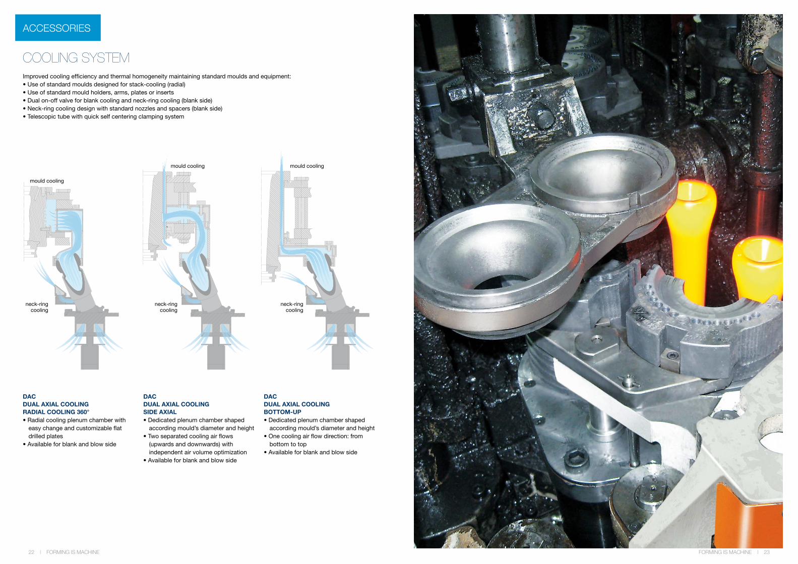
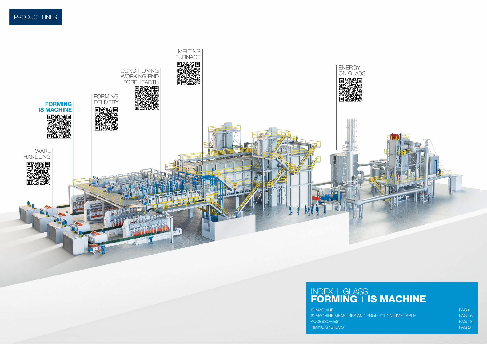
COOLING SYSTEMImproved cooling efficiency and thermal homogeneity maintaining standard moulds and equipment:• Use of standard moulds designed for stack-cooling (radial)• Use of standard mould holders, arms, plates or inserts• Dual on-off valve for blank cooling and neck-ring cooling (blank side)• Neck-ring cooling design with standard nozzles and spacers (blank side)• Telescopic tube with quick self centering clamping system
DACDUAL AXIAL COOLINGRADIAL COOLING 360°• Radial cooling plenum chamber with
easy change and customizable flat drilled plates
• Available for blank and blow side
DACDUAL AXIAL COOLINGSIDE AXIAL• Dedicated plenum chamber shaped
according mould’s diameter and height• Two separated cooling air flows
(upwards and downwards) with independent air volume optimization
• Available for blank and blow side
DACDUAL AXIAL COOLINGBOTTOM-UP• Dedicated plenum chamber shaped
according mould’s diameter and height• One cooling air flow direction: from
bottom to top• Available for blank and blow side
mould coolingmould cooling
mould cooling
neck-ringcooling
neck-ringcooling
neck-ringcooling
ACCESSORIES
22 | FORMING IS MACHINE FORMING IS MACHINE | 23

TIMING SYSTEMS
IS MACHINETIMING
SYSTEMS
ADV 1000ADV 1000 PLUS • User friendly• Low cost basic functions• Possible Servo Feeder Control• From 4 up to 12 sect,• Single gob, Double Gob, Triple Gob.• Tandem Capability
The Control is made up of One CPU per section controller for each 4 sections, Independent MS and EME-Stop with certified safety relay per each section and servo motor to fit CE safety requirements, Ethernet communication and remote access.
Machine Controls for Servo Plunger, Servo Parallel Shear, Servo Gob Distributor; on demand: Servo Tube Height Positioning and Servo Tube Rotation.
Integrated Drive Controller For Mechanical Feeder (when the Servo Feeder is not present), Conveyor, Transfer and Cross Conveyor.
The Section Controller has 48 outputs, Free assignable events to outputs with attributes for blank or blow side, Integrated electric pusher with step motor, Individual Ware-Rejection with manual or automatic stop, Special cycles.
INTEGREX • Simple but effective integrated
electronic control system to move from mechanical IS machine
• Compact electric cabinet• Integrated control system• Reduced set of cables from cabinet to
the machine• Unique control board as with PLC and
Operator’s interface functions• From 4 up to 10 sect,• Single gob, Double Gob,
Drive Controller: max 4 motors for brushless motors.Electro-mechanical pusher controlServo gob distributor control.The Section Controller has max 48 (32 on valves block, 8 blank side, 8 blow side).
ADV 8000 • Servo Mechanisms Control• Stand Alone Mechanisms Control• Energy Saving With AFE Technology• From 6, up to 12 sect• Single, Double, Triple or Quad Gob• Tandem Capability
The Control is made up of Individual section controller and 24 VDC power supply (one per section), Independent MS and E-Stop with robust safety relay per section and servo motor to meet CE requirements, Ethernet communication and remote access through internet or telephone modem.
Machine Integrated controls for Servo Plunger, Servo Tube Height Positioning, Servo Tube Rotation, Servo Parallel Shear, Servo Gob Distributor, BDF-CWD Conveyor Ware DetectorIntegrated Drive Controller For Mechanical feeder, Conveyor, Transfer, Cross conveyor, BDF Dual Axes servo stacker.
ADV SERIES - MUTUAL FEATURES• Complete integrated control system for control of the entire machine operation from
stirrer to ware handling• Real time telediagnostic• Automatic set of feeder mechanism, gob distributor mechanism, machine, transport
line, articles reject according to the production changes• Open system with field bus architecture• Modular machine and industrial standard for Hw and Sw, with centralised,
decentralised and with distributed intelligence• Full integration of BDF stand-alone systems in 3rd part timer
24 | FORMING IS MACHINE FORMING IS MACHINE | 25

AFE - ACTIVE FRONT ENDOUR ENERGY SAVING PHILOSOPHYWe consider a complete BDF system equipped with servo plunger, servo shears, servo gob, servo pusher, servo invert and servo take-out mechanisms.
Considering the system from a mechanical point of view, there is a continuous energetic inertial changing due to the continuously mechanisms acceleration and deceleration.
We may say that for every movement the energy needs for the acceleration is balanced with the energy needs for the deceleration, more the energy to compensate the mechanical and electronic losses.These losses are functions of the machine speed.
As the servomechanisms movements are not in the same time, the excesed energy is recovered on the CC BUS.The system takes from the main line only the energy to compensate all the losses (passive energy) that are not compensate from the recovered energy.The system transfer from the main line to the BUS full power (without cutting) with cos=1.
The sinusoidal current is without low harmonic (is remaking signal), and the only harmonic signal present is very low and with high frequency, because depend from the modulation frequency (PWM signal).The converter system on the BDF control cabinet is reversible and recover the energy on the BUS line.
• Sinusoidal line current with reduction of the harmonic
current distorsion THDi• Compensation of line voltage variations• Energy saving• DC BUS Control also with power line
voltage fluctuations• Regenerative capability thus to make
power flow in both directions
AFE Inverter
Power (kW)
Regenerated Power (kW)
ActiveFront End
Mains
Regenerated Power (kW)Wind Power
Hydro Power
Automation
OPDE OPDE
miniOPDE
miniOPDE
miniOPDE
TIMING SYSTEMS
26 | FORMING IS MACHINE

MELTING FURNACE CONDITIONING WORKING END FOREHEARTH FORMING DELIVERY FORMING IS MACHINE WARE HANDLING ENERGY ON GLASS
10/2
018
- st
udio
bran
d.it
In o
rder
to e
nsur
e a
cont
inuo
us im
prov
emen
t of t
he p
rodu
cts,
BD
F In
dust
ries
res
erve
s th
e ri
ght t
o m
ake
mod
ifica
tions
to th
e ch
arac
teri
stic
s an
d pi
ctur
es (w
ithou
t not
ice)
BDF INDUSTRIESS.p.A.HeadquarterViale dell’Industria, 4036100 Vicenza - Italyphone +39 0444 286 100
BDF INDUSTRIESNorth America LLC1821 Dickinson Avenue,Suite E,Dickinson, Texas 77539phone +1 832 404 2292
BDF SERVISD.O.O.Hum Na Sutli 107/4,49231 Hum Na SutliCroatiaphone + 385 (0)49 382 222www.bdf.it
HEADQUARTER BRANCHES REPRESENTATIVES WHERE BDF INDUSTRIES IS ACTIVE