Forest Service AOP - Association of Conservation...
62
Forest Service AOP Meeting Objectives of Stream Simulation: Examples and Talking Points Traci Sylte, P.E. Hydrology/Fluvial Geomorphology Lolo National Forest
Transcript of Forest Service AOP - Association of Conservation...

Forest Service AOP Meeting Objectives of Stream Simulation:
Examples and Talking Points
Traci Sylte, P.E.Hydrology/Fluvial Geomorphology
Lolo National Forest

Is It True?Are Road Crossings a Dam …with a Little Hole? ....
Road-Stream Crossing Objectives: A Win-Win Scenario
Maximize Structure LifeMinimize MaintenanceOptimize SafetyProvide for Species PassageProvide for the Stream
Function and Water Quality
Overview:
Provide Examples and Talking Points of the Essentials to Meeting Primary Stream-Road Crossing Objectives
Designing By Stream Type Designing Dimension, Pattern, Profile Principles and Processes For Structures “Green” Considerations

“Simulate” adjacent natural channelPremise: If the stream channel through the crossing simulates the dimensions, character, and processes of the adjacent natural channel, it will present no more of an obstacle to movement of organisms than the natural channel.

Big Picture: Narrowing Watershed Processes
Floods Fire Mass Failures Debris Torrents Wind Throw Drought Organism Life Cycles Nutrient Cycling Cumulative Human Impacts
2. Wood Transport
3. Sediment Transport
Large Scale Processes What it Means toCrossing Design
4. Species Passage
1. Water Transport
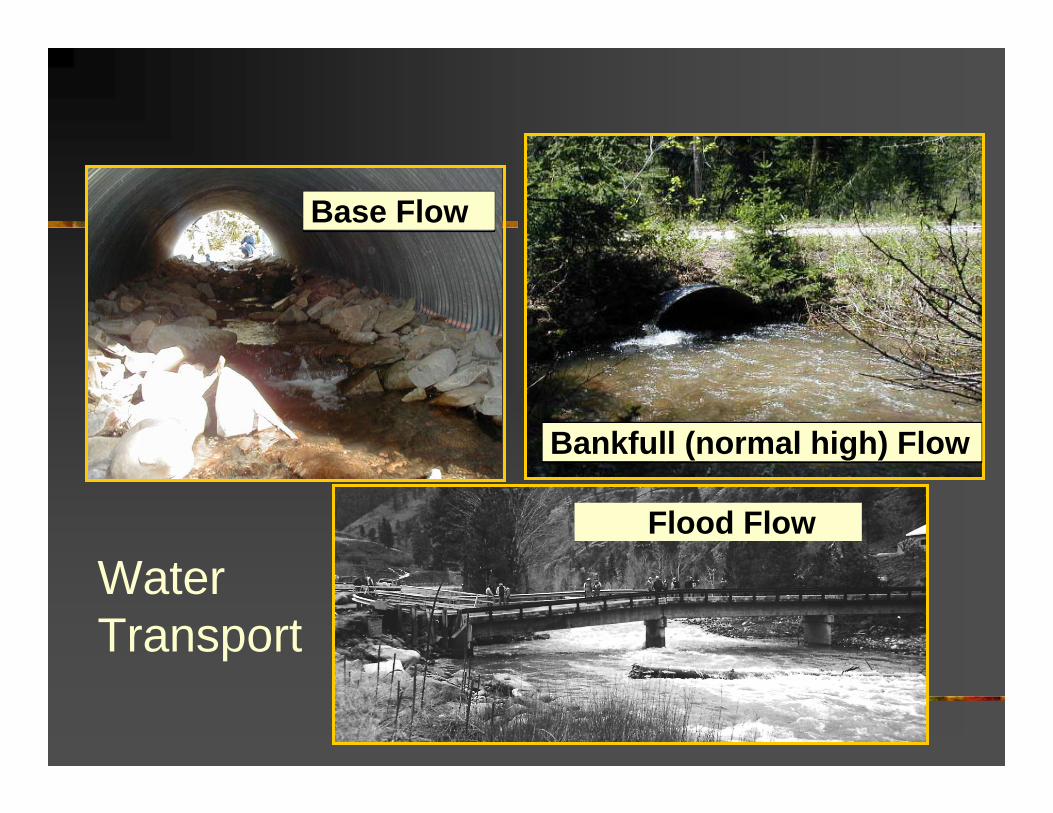
Base Flow
Bankfull (normal high) Flow
Flood Flow
Water Transport
Base Flow
Bankfull (normal high) Flow
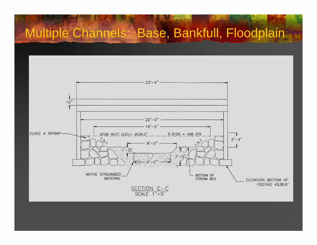
Multiple Channels: Base, Bankfull, Floodplain

Water and Scour
High Velocity
Scour
1979 – Siegel Ck, LNF 1998 – Siegel Ck, LNF

Wood Transport Stream Function – energy dissipation,
grade control Habitat Nutrient Cycling Structure Failure / Maintenance

Sediment Transport
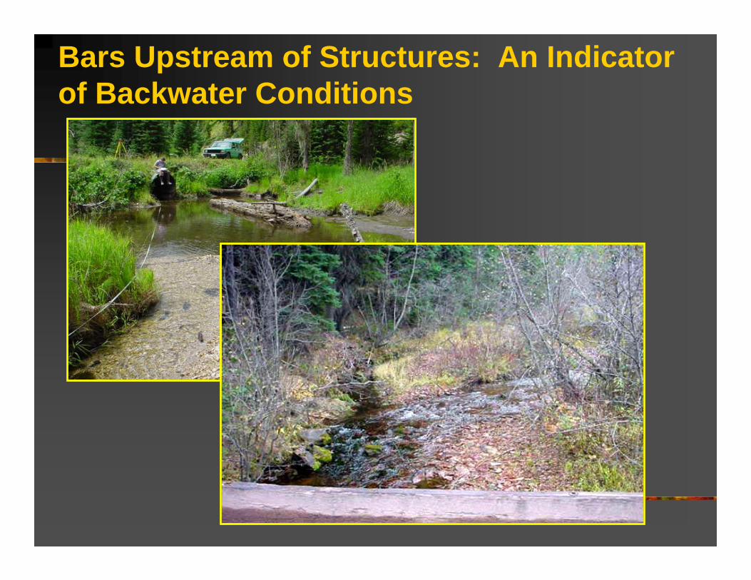
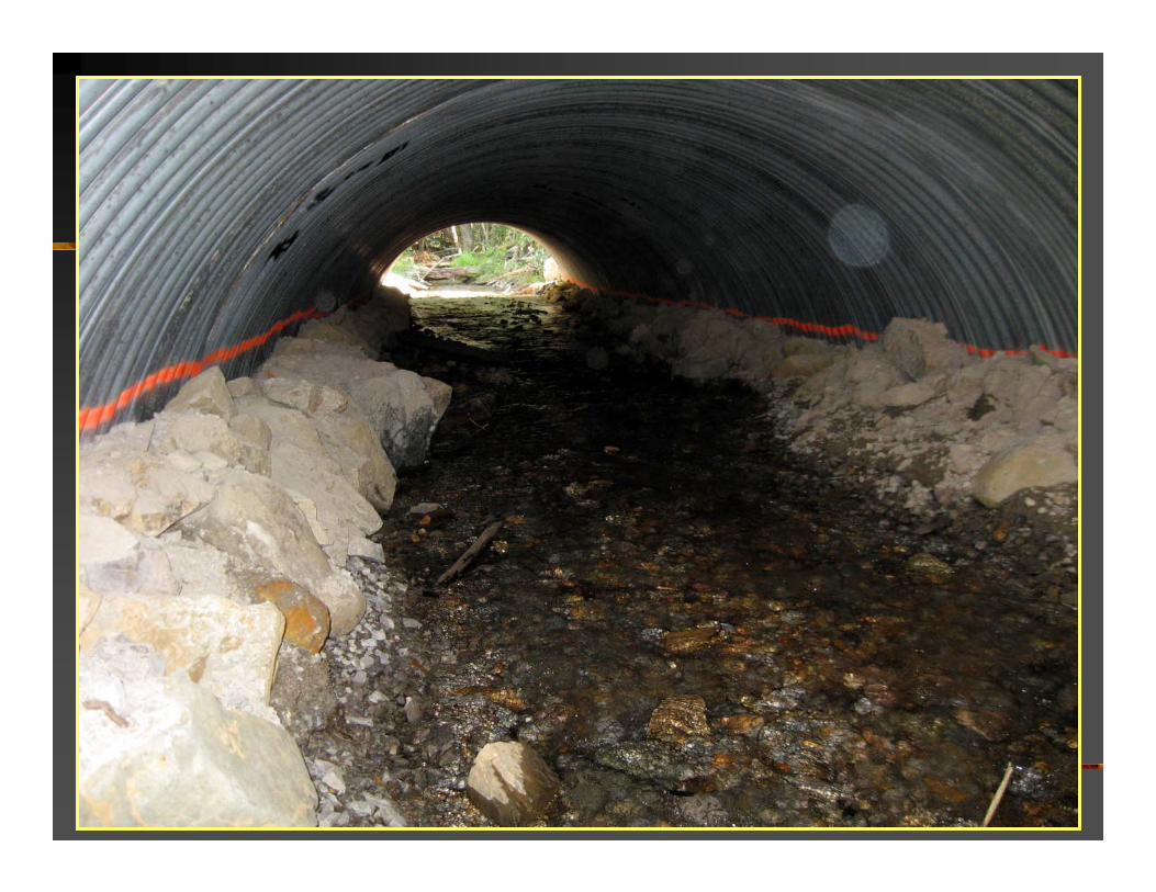
Bars Upstream of Structures: An Indicator of Backwater Conditions

Okay Simulate: but what width, depth, profile, substrate……

Stream Simulation Design: 4 Primary Components
1. Geometric Alignment 2. Channel / Structure gradient 3. Bed width and shape4. Bed material design & channel
forms

From Rosgen 1994
The Channel: Dimension, Pattern, Profile

Some “A” Stream Types
A2
Aa+
A4
A1
- Avalanche chutes, headwaters, faults, bedrock areas
-Steep
-Well entrenched
-Low width/depth ratio
-Step-pools, cascades, waterfalls
-High energy
Montgomery & Buffington “Source or Transport” Streams
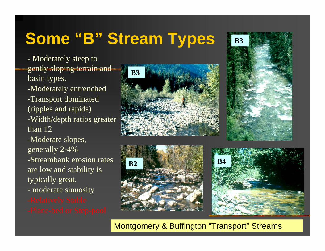
Some “B” Stream Types- Moderately steep to gently sloping terrain and basin types. -Moderately entrenched-Transport dominated (ripples and rapids)-Width/depth ratios greater than 12-Moderate slopes, generally 2-4%-Streambank erosion rates are low and stability is typically great.- moderate sinuosity-Relatively Stable-Plane-bed or Step-pool
B3
B2 B4
B3
Montgomery & Buffington “Transport” Streams

Some “C” Stream Types
C4 – altered with berm
C4 - Reconstructed
C4
C4 -Narrow to wide valleys with well developed floodplains
- Slopes, generally less than 2%
- Stability dependent on stream banks and vegetation
- Sinuous
- Riffle-pool dominated
- Width/depth ratios greater than 12
Montgomery & Buffington “Response” Streams

Some “D” Stream Types
D5
D4
D3
D4
- Multiple channels, braided, multiple bars.
-Steep depositional fans, glacial troughs, deltas, outwash areas, disturbed valley streams- low sinuosity-High bank erosion-Relatively Unstable- channel slope generally similar to valley slope
Montgomery & Buffington “Response” Streams

Some “E” Stream Types
E4
E5a
E4 – altered by grazing
E6
E5
-Very high sinuosity and low gradient, except where altered or in steep mountain meadows- only slightly entrenched/dominant floodplain- most efficient transport per unit width of all stream types-Highly stable, but very sensitive to disturbance and vegetation removal-Width/depth ratios less than 12
Montgomery & Buffington “Response” Streams

Barnard
Bankfull WidthBankfull Width
Stream Simulation

Culvert bed
Shoulder (or bankline if continuous)
Channel margins
10 ft low flow channel
Band
Bed Width and Shape
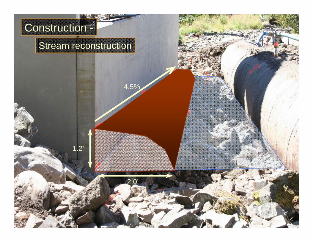
Stream reconstruction
Construction -
1.2’
4.5%
2.0’

Stream reconstruction
Construction -

Culvert Elevation
Bed profile elevationCul
vert
Ris
e
30% D
50% D
Range of possible bed elevation from long profile analysis (Range)
By simple math Culvert Rise > 5 x Range


“Like a two year old child, a river can’t sit still,” Mount, 1995
Planform...Meandering Tendency
Bending is a central tendency….it’s all about physics.

Planform Considerations: Designing for Bends1. Avoid Sinuous Channels 2. Locate Crossings on
Straight Sections3. If Straightening is
Necessary - Do Not Straighten the Stream Longer than its Natural Meander Wavelength (Don’t make the distance between bends or pools longer than the natural ranges)
4. Accept Small Skews and Reinforce Banks If Necessary
5. May Need to Perform Channel Restoration to Recreate Natural Geometries
** Work Within the Natural Meander Geometry of Your Stream Type!!!!!
Differs by Stream Type

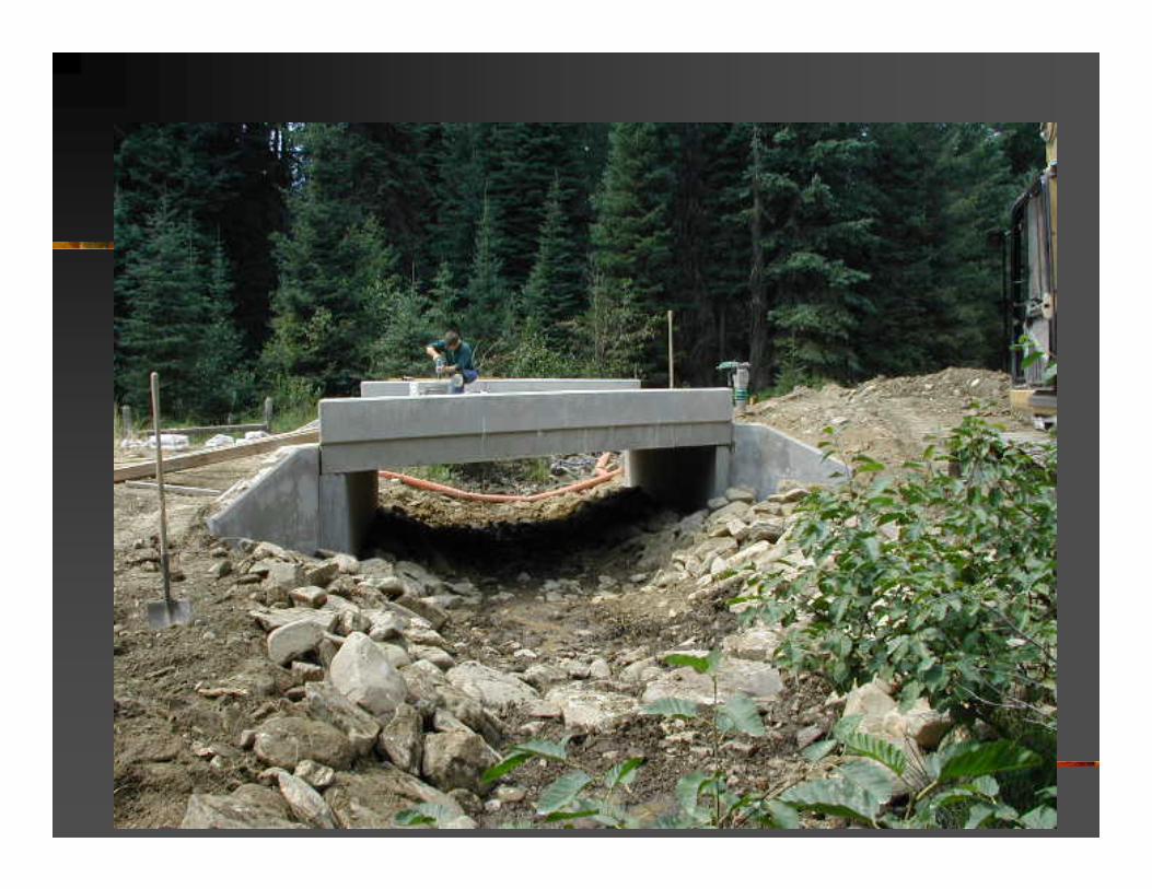
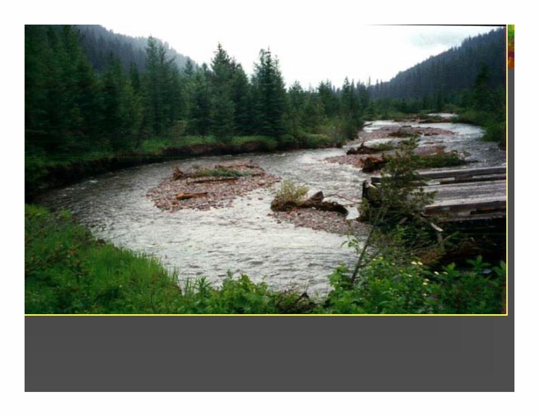
Crossing replacement accommodated the bankfull channel dimensions, but quickly filled again because it is located at a channel grade change between a C4 and D4 channel type. Moving the road 200 feet upstream to a B4 channel type would have transported all material efficiently through the crossing.
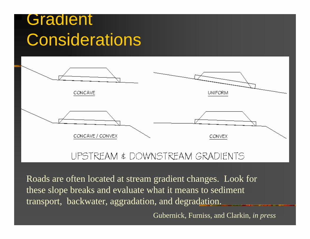
Gradient Considerations
Gradient Considerations
Gubernick, Furniss, and Clarkin, in press
Roads are often located at stream gradient changes. Look for these slope breaks and evaluate what it means to sediment transport, backwater, aggradation, and degradation.
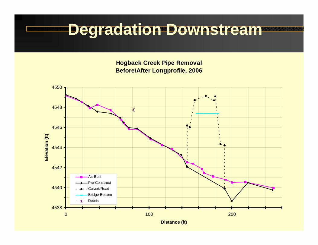
Hogback Creek Pipe RemovalBefore/After Longprofile, 2006
4538
4540
4542
4544
4546
4548
4550
0 100 200
Distance (ft)
Elev
atio
n (ft
)
As BuiltPre-ConstructCulvert/RoadBridge BottomDebris
Degradation Downstream

Remedy to Degradation at Outlet

Bedform and Substrate
Profile Planform
A Cascade
B Step-pool
C Plane-bed
D Pool-riffle
E Dune-ripple

Channel Bed Form and Substrate

Finished profile
1. Sub-grade access pad
2. Bed material to final grade
3. Step pool footer
4. Additional bed material
5. Top step pool rock
6. Bed material to grade
Construction of Steps


Other Substrate Considerations
-Account for Armor Layer & assure fines are incorporated.
- Mimic natural substrate sizes & distributions
- Failure to do so can result in:
•Subsurface Flows
•Scour of Substrates


Other Talking Points

Floodplain Connectivity: Unconfined channel • Hydraulic / Stability analysis when floodplain conveyance high• Increase culvert width• Improve inlet contraction• Add floodplain culverts (when either Q10 floodplain > 4 x BFW ?)• Add road dips• Increase bed material size

This is an E4 stream type where the culvert spanned the bankfull channel width, but did not allow for floodplain flows. It failed periodically requiring both road and culvert maintenance until a bridge structure was installed.
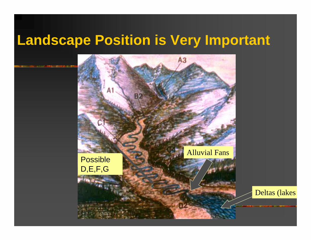
Landscape Position is Very Important
Deltas (lakes
Alluvial FansPossible D,E,F,G

Lightening Creek

Bankfull Identification- Responsible for general channel shape and size - Transports more sediment over time than any other discharge- Occurs on average every 1.0 –3.0 years- Common pseudonyms: “active channel”, “ordinary high water mark”, and “Q2”

Bankfull Indicators Top of Flat Depositional
Areas
Change in vegetation
Slope Breaks
Change in particle sizes between bed, banks, and floodprone area
Bank undercuts, root, and scour lines
Stain or lichen lines on boulders
tls 5/7/03

Bankfull Indicators
seek local expertise
verify local indicators!
Is it? Is it not?

Lolo Creek Boulder Clusters – 1980’s
Lolo Creek Boulder Clusters – 2005
Stability in Substrate Design

1 2 3
A Principle of Scour & Settlement Protection
Settlement and Mobility Process by Un-Protected Downstream Scour
Structure Design For Stability – Each of these will provide stability

Structures & Principles We must work with channel hydraulics with our structures.
Check structures impede velocity and bedload transport, often flank and/or scour, and over-widen channels
Bad, bad, bad……

Good, good, good……

DESIGNERS: Reality Check!!!!!!!!Average Stream Velocities(Spring Runoff or Slightly Greater)
Mountain streams - 4-5 ft/s.
Valley streams - 4-6 ft/s.

Velocity (feet/second)4 8 12 16 20 24 280 32 36
Chinook
Steelhead
Coho
Cutthroat
Brown Trout
Grayling
Whitefish
M. Bell 1989
Cruising SpeedSustained SpeedDarting Speed
Critical Velocities for our fish: 4-5 fps (We shouldn’t be surprised)
HEALTHY ADULTS
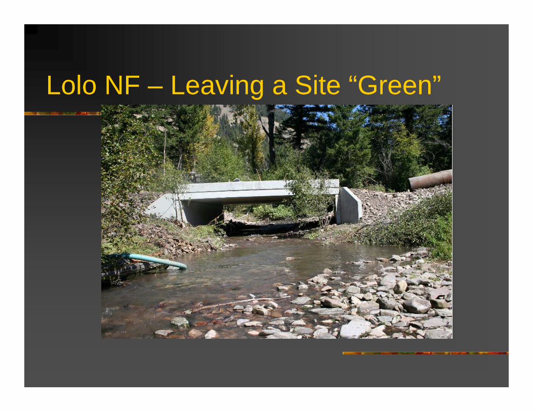
Lolo NF – Leaving a Site “Green”

Geomorphic and Analytical Approaches to Stream Rehabilitation Design and Reconstruction Have Taught Us A Lot. Incorporate them.


Design Advancements
“Bad Riprap”
“Good” Riprap
Good Riprap Design: 1. Used where excluding lateral stream movement is not a detriment or is not feasible2. Designed irregular bank line and rock protrusions dissipate energy and create habitat
niches at multiple flow levels3. Only protects to a designed flood level, often bankfull or Q100 are used4. Incorporates vegetation and creates habitat5. Of course, has necessary size classes and configuration to remain stable


Is It True?Are Crossings a Dam with a Little Hole? ...IT DOESN’T HAVE TO BE!

Acknowledgments for Slides and Photos
Lolo National Forest et. al.
Shane Hendrickson, R1 John Casselli, R1 John Kattel, R1 Pete Odegard, R1 Rod Blessing, R1 Chad Bensen, R1 Bob Gubernick, R10 Kim Johansen, R6 Dan Cenderelli, R6 Thomas Dunklin