FORCE-POSITION CONTROLLER DESIGN FOR 4 DOF… 39th volume/7 REHABILITATION ROBOT ARM.pdf · robotic...
15
International Journal of Information Technology and Business Management 29 th July 2015. Vol.39 No.1 © 2012-2015 JITBM & ARF. All rights reserved ISSN 2304-0777 www.jitbm.com 84 FORCE-POSITION CONTROLLER DESIGN FOR 4 DOF'S REHABILITATION ROBOT ARM USING PSO ALGORITHM Asst. Prof. Dr. MOHAMMED Y. HASSAN Mr. ZEYAD A. KARAM [email protected] [email protected] Control and Systems Engineering Department University of Technology Baghdad, Iraq ABSTRACT: Human limbs disability such as full or partial loss of function of the upper limb is a common impairment in the elderly and due to strokes, sports injuries, and occupational injuries. The conventional rehabilitation approach is to assist patient to perform Activities of Daily Living (ADL) through a set of pre- programmed trajectories. Therapist performs the rehabilitation program to the patient. This work focuses on designing, simulating and implementing a 4 DoF's (3 active joints), non- wearable rehabilitation robot for arm movements. The nonlinear mathematical model of the robot includes kinematic and dynamic models for the 4 DoF's (3 active joints), is developed and simulated using MATLAB. The friction term of robot actuators with the external disturbances of the patient limb on the robot links are considered. Intelligent Force-Position controllers incorporated PD-like Fuzzy Logic position control are designed to track the required medical trajectories for the simulated and implemented robot. Particle Swarm Optimization (PSO) algorithm is used to tune the gains of the position part of the Force- Position controller's to reach minimum position error, minimum oscillation and minimum overshoot in the position of each joint. These controllers are implemented using MATLAB Simulink. The controllers are controlling the implemented rehabilitation robot using two Data Acquisition Cards (Advantech PCI-1712), which generate and reads the required digital and analog signals for the robot. Index Terms: Force-Position control, Rehabilitation robot, Intelligent controller, Robot dynamics, Medical trajectories, PSO algorithm, Advantech card. I. INTRODUCTION Robotics sciences are playing as important domain in several applications; like industrial and medical applications. Robotics are using in rehabilitation programs and many other medical processes. Therapist performs the rehabilitation program but the drawback in the method of treatment may occur in incorrect therapeutic movements which result from fatigue therapist during the treatment section. This is leading to a negative impact on the patient person. Here comes the role of the robot. Which leads movements consistent and repeated tirelessly or fatigue that can be used in hospital or at home for assisting in ADL and many patients can work with it at day [1]. The drawback was in the wearable position and alignment for the human hand. Ueda et al. in 2011 [4], proposed a new method, named (individual muscle-force control), for a wearable robot. The main drawback was the workspace limitations with not considering the friction term in pneumatic actuators. Stiffness and impedance control concepts proposed by Mehdi and Boubaker in 2012 to solve position and force control for robot-aided rehabilitation. The main drawback in this work is not accurate tracking for the desired medical trajectory [5]. In this work, the intelligent controller for 4 DoF's (3 active joints), non-wearable rehabilitation robot is designed to control the simulated and implemented robot. The nonlinear mathematical
Transcript of FORCE-POSITION CONTROLLER DESIGN FOR 4 DOF… 39th volume/7 REHABILITATION ROBOT ARM.pdf · robotic...

International Journal of Information Technology and Business Management 29
th July 2015. Vol.39 No.1
© 2012-2015 JITBM & ARF. All rights reserved
ISSN 2304-0777 www.jitbm.com
84
FORCE-POSITION CONTROLLER DESIGN FOR 4 DOF'S REHABILITATION
ROBOT ARM USING PSO ALGORITHM
Asst. Prof. Dr. MOHAMMED Y. HASSAN Mr. ZEYAD A. KARAM
[email protected] [email protected]
Control and Systems Engineering Department
University of Technology
Baghdad, Iraq
ABSTRACT:
Human limbs disability such as full or partial loss of function of the upper limb is a common
impairment in the elderly and due to strokes, sports injuries, and occupational injuries. The conventional
rehabilitation approach is to assist patient to perform Activities of Daily Living (ADL) through a set of pre-
programmed trajectories. Therapist performs the rehabilitation program to the patient.
This work focuses on designing, simulating and implementing a 4 DoF's (3 active joints), non-
wearable rehabilitation robot for arm movements. The nonlinear mathematical model of the robot includes
kinematic and dynamic models for the 4 DoF's (3 active joints), is developed and simulated using
MATLAB. The friction term of robot actuators with the external disturbances of the patient limb on the
robot links are considered. Intelligent Force-Position controllers incorporated PD-like Fuzzy Logic position
control are designed to track the required medical trajectories for the simulated and implemented robot.
Particle Swarm Optimization (PSO) algorithm is used to tune the gains of the position part of the Force-
Position controller's to reach minimum position error, minimum oscillation and minimum overshoot in the
position of each joint.
These controllers are implemented using MATLAB Simulink. The controllers are controlling the
implemented rehabilitation robot using two Data Acquisition Cards (Advantech PCI-1712), which generate
and reads the required digital and analog signals for the robot.
Index Terms: Force-Position control, Rehabilitation robot, Intelligent controller, Robot dynamics, Medical
trajectories, PSO algorithm, Advantech card.
I. INTRODUCTION
Robotics sciences are playing as important
domain in several applications; like industrial and
medical applications. Robotics are using in
rehabilitation programs and many other medical
processes. Therapist performs the rehabilitation
program but the drawback in the method of
treatment may occur in incorrect therapeutic
movements which result from fatigue therapist
during the treatment section. This is leading to a
negative impact on the patient person. Here comes
the role of the robot. Which leads movements
consistent and repeated tirelessly or fatigue that can
be used in hospital or at home for assisting in ADL
and many patients can work with it at day [1]. The
drawback was in the wearable position and
alignment for the human hand. Ueda et al. in 2011
[4], proposed a new method, named (individual
muscle-force control), for a wearable robot. The
main drawback was the workspace limitations with
not considering the friction term in pneumatic
actuators. Stiffness and impedance control concepts
proposed by Mehdi and Boubaker in 2012 to solve
position and force control for robot-aided
rehabilitation. The main drawback in this work is not
accurate tracking for the desired medical trajectory
[5].
In this work, the intelligent controller for 4
DoF's (3 active joints), non-wearable rehabilitation
robot is designed to control the simulated and
implemented robot. The nonlinear mathematical

International Journal of Information Technology and Business Management 29
th July 2015. Vol.39 No.1
© 2012-2015 JITBM & ARF. All rights reserved
ISSN 2304-0777 www.jitbm.com
85
main reason of developing robotic treatments is the
current emphasis on cost reduction in health care
through shorter patient rehabilitation length [2].
Xianzhi et al. in 2010 [3], designed a hybrid
force position controller using fuzzy logic for the
robotic arm of 9 DoF's for the upper limb of
wearable exoskeleton rehabilitation robot. The
model for the proposed rehabilitation robot is
derived and simulated by Matlab. Also, the effect of
the friction in the joints and the external disturbances
that affect in the rehabilitation robots when touched
to the patient body are considered in the robot
model. The controller is a Force-Position controller
incorporates PD-like Fuzzy logic position
controllers to deal with the force and position that
affect on the robot links by the patient limb.
A Particle Swarm Optimization Algorithm
(PSO) is used to tune the Position part of Force-
Position controller's gains to get the desired medical
trajectories with minimum position error, minimum
overshoot and minimum oscillation in the simulated
robot tests.
II. DESIGNING AND MODELING OF 4 DOF'S
REHABILITATION ROBOT The overall structure of proposed 4 DoF's
rehabilitation robot for human upper limb motion
design is shown in Figure 1. This structure is
manufactures with respect to medical designs of
rehabilitation robots. The mechanical design of the
robot and structure was presented in [6]. .
Kinematical model:
In this research, the proposed rehabilitation
robot is modeled based on the concepts of, human
upper limb articulations and movements to
rehabilitate and to ease shoulder and elbow joint
motions to assist human daily activity properly. The
rehabilitation device has three degrees of freedom,
which are:
Shoulder abduction/adduction (one DOF).
Shoulder flexion/extension (one DOF).
Elbow flexion-extension (one DOF).
The DH parameters according to co-ordinate
frames that presented in [9], are listed in Table (1). The homogenous transformation matrix that
relates frame (4) to frame (0) can be obtained by
multiplying individual transformation matrices [7]:
= (1)
Dynamic model: Using the Euler–Lagrangian formulation, the
dynamics of robot manipulators with rigid links can
be written as [7]:
depends on many factors such as lubrication,
temperature, interaction surface, displacement and
relative velocity of robot. It is highly nonlinear
effect and result in steady state errors, limit cycles,
and poor performance [8]. The friction model with
its simulation was present in [9]. In this work, the
singularity occurs at configuration of end effector
with the base of robot. This configuration is similar
to the articulated configuration 3 DoF's. The singular
configuration with its solution was present in
[6].Figure 2 shows the block diagram of dynamic
model and Figure 3 shows the simulink model of 4
DoF's (3 active joints), rehabilitation robot. The
parameters of the dynamic model were presented in
[9].
III. Design and Simulation of Force-Position
Controlled Rehabilitation Robot Force-Position controller is a control strategy
specifying a desired dynamic behavior for the robot.
The most common feature in many robotic
applications is the motion of the robot manipulator
within an unconstrained space like the end effector
and the links of the manipulator are not in contact
with the environment. Force-Position control was an
approach considers the relationship between the
position of the manipulator and the contact forces
imposed by the environment. This relationship can
be modeled by generalized
Force-Position characterized by inertial,
damping and stiffness properties, associated to the
manipulator [10]. The contact between the
manipulator and its environment results in increasing
the complexity of the industrial processes that need
for robotic technology demands. Taking this
problem in consideration, results in a new control
problem. The objective of the Force-Position control
strategy is the successful execution of an interaction
task with the environment. Such an interaction

International Journal of Information Technology and Business Management 29
th July 2015. Vol.39 No.1
© 2012-2015 JITBM & ARF. All rights reserved
ISSN 2304-0777 www.jitbm.com
86
( ) ̈ ( ̇) ̇ ( ̇) ( ) (2)
Where q ∈ denotes the vector of generalized
displacements, τ ∈ denotes the vector of
generalized control input torques, D(q) ∈ is the
inertia matrix, ( ̇) ∈ is the Coriolis matrix,
F( ̇) ∈ are the Friction terms, G (q) ∈ is the
gravity vector, and ∈ represents disturbances
which are bounded [7]. Friction model and singularity solution: Friction is an undesirable phenomenon in the
performance of controlled electromechanical motion
systems. The effect of friction on robotic system
requires the control of both, motion and interaction
forces [11].
The robot controller is designed to track the
motion trajectory and realize the desired force
dynamics between the end-effecter position and the
contact force the desired force is defined as [12]:
F ( ) ( ̇ ̇) ( ̈ ̈) (3)
Where F ∈ is the vector of contact generalized
forces exerted by the manipulator on the
environment; P is the task space dimension. ,
and ∈ are the desired stiffness, damping
and inertia matrices respectively, X, ̇ and ̈ ∈ are
the position, velocity and acceleration
respectively of the robot system in the Cartesian
space. The control law of the force that is applied to
the dynamic model of robot is [13]:
U = ( ) [ ( ) + ( ̇ ̇ ) + ( +I)
− F] +G
(4)
Figure 4 represents the block diagram of closed loop
Force-Position controlled system for 4 DoF's
rehabilitation robot, where U ∈ is the control law
applied to robot model, J(q) ∈ is the Jacobean
matrix and , and ∈ are the position,
velocity and force gain matrices, respectively. All
design of the controller with it parameters was
present in [9].
The Position part controller of each joint that
incorporating in the Force-Position control is; a PD
like Fuzzy Logic type (FLC) to deal efficiently with
the nonlinearities in robot mode and tracking the
desired medical position trajectories with minimum
overshoot and minimum oscillation. All Fuzzy
controller parameters and membership functions
with rules table was present in [9]. The parameters
of the Force controller incorporating in the Force-
Position control, of equation 10 are selected as;
Kd=60 (N/m), Bd=150 (N·s/m) and Md=2 (kg).
These values are representing second order model
with damping ratio and un-damped natural
frequency of ζ=0.785 and wn=0.523 (rad/sec)
respectively [10]. The objective of this control
concept is to accomplish specific mechanical
This trajectory is transformed into Cartesian
coordinates using the direct kinematics in order to
obtain the desired trajectory = where:
( ) (6)
(t) = cos ( ) cos ( + ) (7)
( ) Sin ( ) sin ( ) (8)
Where ( ) [i=3, 4] is the generated angle
for the desired trajectory. Assuming the desired force
of = (N) is applied to the first position
trajectory in the (Y, Z) axes motion and assume the
position in the X axis is fixed at 0.148 (m). The gains
of the PD-like position FLC for first position
trajectory parameters are selected using trial and error
as illustrated in Table (2):
The closed loop Force-Position controlled of
position responses for the first trajectory of the end
effecter without disturbance is shown in Figure 6. The
position response with the affect of (0.05sin (0.5ωt))
as disturbances N.m are shown in Figure 7. The
second reference position trajectory of half ellipse is
applied to move the three joints together at the same
time. The parameters of controller are selected by trial
and error for the second half ellipse trajectory and
illustrated in Table (3):
Figure 8 show the position responses of the
second trajectory on end effector without
disturbances. The position response of the second
trajectory with (0.08 sin ( )) as disturbance on the
forth joint is shown in Figure 9.

International Journal of Information Technology and Business Management 29
th July 2015. Vol.39 No.1
© 2012-2015 JITBM & ARF. All rights reserved
ISSN 2304-0777 www.jitbm.com
87
impedance at the manipulator end-effector. The
manipulator controller is designed to track a motion
trajectory and realize a desired dynamic relationship
between the end effector position and the contact
force [11]. The Simulink that represents the closed
loop Force- Position controller of the rehabilitation
robot was shown in Figure 5.
IV. MEDICAL TRAJECTORIES WITH
SIMULATION RESPONSES Two reference position trajectories were applied;
the first position trajectories are generated by using
a cubic interpolation and its two axes trajectory. The
initial and final end effecter joint angles of the robot
are ( ( ) ( ) ), ( ( ) ( ) ) and ( ( ) ( ) ) for shoulder abduction respectively, where ( ) is
the initial time and ( ) is the final time of motion.
The trajectory is the time of planning in such a way
that the robot arrives at the final configuration in = 60 (s). The planned trajectory is [11]:
( ) ( ) [ ( ) ( )
] [
( ) ( )
]
(5)
V. PSO AS AN OFF-LINE POSITION
CONTROLLER GAINS TUNING ALGORITHM
In PSO algorithm, each member of the
population is called a ‘‘particle’’, and each particle
‘‘flies’’ around in the multidimensional search space
with a velocity, which is constantly updated by the
particle’s own experience and the experience of the
particle’s neighbors or the experience of the whole
swarm. It has already been applied in many areas,
such as function optimization, artificial neural
network training, pattern classification and fuzzy
system control [13].
The particle swarm optimization (PSO)
algorithm is performed as follows:
1) The unknown parameters are called the
particles that form the population size denoted by
n.
2) Starting with a randomly initialization, the
particles will move in a searching space to
minimize an objective function.
3) The parameters are estimated through
minimizing the objective function.
4) The fitness of each particle is evaluated
according to the objective function for updating
the xpbest (previous best position) of particle and
the xgbest (global best position) among all
particles as two goals in each step of computing.
5) Each particle is directed to its previous
xpbest position and the previous xgbest position
among particles.
Consequently, the particles tend to fly towards the
better searching areas over the searching space. The
velocity of i-th particle will be calculated as [13]:
( ) ( ( ) ( ( ) ( ))+ (gbest − (k))) (9)
Where for the i-th particle in the k-th iteration, ( ) is the position, ( ) is the previous best
position, (gbest) is the previous global best position
of particles, ( ) and ( ) are the acceleration
coefficients namely the cognitive and social scaling
parameters, ( ) and ( ) are two random numbers
in the range of [0 1] and (χ) is constriction
coefficient given by [13]:
√ (10)
VI. PSO-BASED FORCE-POSITION CONTROL
SIMULATION RESPONSES
The fitness function is selected as (for all cases
of using PSO):
F=RMSE*0.95+ (overshoot*0.05) (13)
For the first medical trajectory without
disturbances More than ten tests have been done to
tune the gains of the controller using PSO. Table (4)
illustrates the best three values of gains according to
correction criteria (Percentage of enhancement) and
Table (5) illustrates the gains for each case that
obtained by PSO.
Table (4) illustrates that the second trial gives
the higher percentage of correction (minimum
fitness). Figure 11 shows the first position trajectory
response obtained using PSO-based controller.
For the first medical trajectory with previous
disturbance more than ten tests have been done to tune
the gains of the controller using PSO with
disturbance. Table (6) illustrates the best three values
of gains according to correction criteria (Percentage of
enhancement), and Table (7) illustrates the gains for
each case that obtained by PSO.

International Journal of Information Technology and Business Management 29
th July 2015. Vol.39 No.1
© 2012-2015 JITBM & ARF. All rights reserved
ISSN 2304-0777 www.jitbm.com
88
Where (ϕ = , ϕ > 4), Constriction
coefficient is controlled by the convergence of the
particle. As a result, it prevents explosion and
ensuring convergence. A new position of the i-th
particle is then calculated as:
( ) ( ) ( ) (11)
The particle swarm is used as an
optimization algorithm (off-line) to find the best
gains of Fuzzy PD-like position controller to obtain
accurate position responses by minimizing the error
in the position trajectories and minimizing the
overshoot in position responses. This minimization
gives closer matching between the desired and the
actual trajectories. The PSO runs off-line, thus
computing time is not as important as in real time
control. All elements of PSO are changed for many
tests until reach the largest enhancement at
minimum fitness function. Figure 10 shows the
block diagram for PSO-based controller.
The fitness function that used to evaluate the
fitness of each particle the Root Mean Squared
Error (RMSE) and the overshoot in position
responses are included in the fitness function. The
RMSE that included is [13]:
( )
∑ √
( ) ( )
( ) (12)
Where (i) is the trajectory error of the i-th
sample for the first joint, (i) is the trajectory error
of the i-th sample for the third joint and (i) is the
trajectory error of the i-th sample for the fourth
joint, N is the number of samples, and k is the
iteration number.
Table (6) illustrates that the third trial gives the
higher percentage of correction (minimum fitness).
Figure 12 shows the first position trajectory response
obtained using PSO-based controller.
For the second half ellipse medical trajectory
More than ten tests had done to tune the gains of the
controller using PSO. Table (8) illustrates the best
four values of gains according to correction criteria
(Percentage of enhancement) and Table (9) illustrates
the gains for each case that obtained by PSO.
Table (8) illustrates that the first trial gives the
higher percentage of correction (minimum fitness).
Figure 13 second (half ellipse) position trajectory
response obtained using PSO-based controller.
For the second half ellipse medical position
trajectory with previous disturbance more than ten
tests had done to tune the gains of the controller using
PSO with disturbance. Table (10) illustrates the best
three values of gains according to correction criteria
(Percentage of enhancement), and Table (11)
illustrates the gains for each case that obtained by
PSO.
Table (10) illustrates that the first trial gives
the higher percentage of correction. Figure 14 shows
the second (half ellipse) position trajectory response
obtained using PSO-based controller.
VII. THE IMPLEMENTED ROBOT TEST
All implementation for the mechanical
structure and the interfacing system for controlling
the physical robot actuators can be shown in [7],
Figure 15 shows the input/output blocks of
Advantech chard by MATLAB for interfacing the
Force-Position controller with hardware parts via
two card. The previous quadratic medical trajectory
used in the physical robot tests, two tests are applied
angle only in . Table (12) illustrates the controller
parameters of manual tuning by trial and error.
Figure 16 shows the position trajectory
responses of the first test. he second test of the
position medical trajectory includes applying a 0 to
the third joint angle and 5 to the fourth joint angle
and the first angle assumed in the rest position with
controller does not compensate the effect of friction
and other nonlinearities that exist in the model.
PSO algorithm is used to tune the gains of
position part of the Force- Position control for
minimized the position error, minimized oscillation
and minimized overshoot of medical trajectories in the
simulated robot model. The enhancements in the
position trajectories are illustrated in Table (16),
compared with the conventional one, which were
measured using RMSE criteria.
The results give an indication about the enhancement
in the position trajectories responses of minimized
overshoot and error in position.
In the implemented robot medical trajectory
tests the RMSE is calculated for each test to obtain the
enhancement between conventional Force-Position

International Journal of Information Technology and Business Management 29
th July 2015. Vol.39 No.1
© 2012-2015 JITBM & ARF. All rights reserved
ISSN 2304-0777 www.jitbm.com
89
0 . The Force–Position conventional controller gains
for second test are illustrated in Table (13) and
chosen by trial and error. Figure 17 shows the
position trajectory response of the second test.
The PSO algorithm is used in the
implemented robot tests to tune the parameters
gains of the controllers to generate trajectory
responses with minimum overshoot, minimum rise
time and minimum errors in position trajectory. The
best gains used for the first test are illustrated in
Table (14).
Figure 18 shows the position trajectory
response of the first test using PSO. Also, the PSO
algorithm is used in the second test of the position
medical trajectory to tune the parameters gains of
the controller. Table (15) illustrates the gains of
Force-Position controller obtained by PSO. Figure
19 shows the position trajectory response of the
second test with PSO.
VIII. CONCLUSIONS
It can be concluded from this work that:
Force-Position controllers incorporate a PD-
like fuzzy logic position controllers were used to
control the simulated and implemented robot. These
controllers deal with injured limb force and
minimize the oscillation and the overshoot in the
medical trajectories. For the Force-Position
conventional controller test, the maximum errors
exist in each axis without applying disturbance is:
40 (mm) in X axis and 3 (mm) in Y axes. By
applying disturbances, the maximum error found to
be 20 (mm) in X axis and 10 (mm) in Y axes.
Comparing these results with the Force-Position
controller used in reference [12], it is found that the
position of the end effecter in the mentioned
reference is fluctuated around the desired trajectory
because this type of
controllers and PSO-based controllers. Table (17)
illustrates the RMSE enhancement for the two tests of
position medical trajectory.
Finally, the proposed robot can be used at
homes and hospitals for the stroke injured persons to
get their daily life activates instead of therapists with
correct medical trajectories. The development of the
rehabilitation robots is the current emphasis on cost
reduction of the health care through shorter length for
the patient rehabilitates achieved by using robots.
IX. List of Tables Table (1) DH parameters.
1 0 0 2 0 3 0 0 4 0 0
Table (2) Gains of the PD-like FLC.
Gain
KP1 KV1 KO1 KP2 KV2 KO2 KP3 KV3 KO3
1 0.1 25 4 0.1 22 3 0.01 7
Table (3) PD-like position FLC gains for the second (half ellipse) trajectory.
Gain KP1 KV1 KO1 KP2 KV2 KO2 KP3 KV3 KO3
3 1 25 8 1 22 3 1 10
Table (4) Tests for the first position trajectory without disturbance.
Trial
Fitness by
conventional
controller
Global
Fitness
using
PSO
C1 C2
Number
of
Iterations
Number
of birds
Percentage of
enhancement
1 0.0090 0.0065 3 2 50 25 27.777%
2 0.0090 0.0054 3 3 50 30 40%
3 0.0090 0.0065 2.5 2.5 30 30 27.777%
Table (5) Gains of the controller that obtained by PSO for the first position
trajectory without disturbance.
Gains KP1 KV1 KO1 KP2 KV2 KO2 KP3 KV3 KO3
First
trial
0.0100 0.0100 0.0100 6.5878 0.5784 3.6587 5.3378 2.3390 8.4337
Second
trial
1.2725 1.2933 2.3211 7.8968 1.0418 3.6029 6.5446 0.5129 10.9934
Third
trial
0.5722 1.7910 1.7684 3.9034 2.0303 2.2109 6.0479 3.0921 9.5513
Table (6) Experiments for the first trajectory position with disturbance.
Trial
Fitness by
conventional
controller
Global
Fitness
using
PSO
C1 C2
Number
of
Iterations
Number
of birds
Percentage of
enhancement
1 0.0067 0.0062 3.5 3.5 30 40 7.462%
2 0.0067 0.0052 3.2 3.2 30 35 22.388%
3 0.0067 0.0046 3 3 25 50 31.343%
Table (7) Gains of the controller that obtained by PSO for first position
trajectory with disturbance.
Gains KP1 KV1 KO1 KP2 KV2 KO2 KP3 KV3 KO3
First
trial
0.9571 1.7661 0.7244 7.1753 10.9180 3.7042 4.1858 1.9533 5.9531
Second 2.6968 1.5353 0.0100 17.0000 5.1432 3.4535 12.1037 2.7169 3.2169

International Journal of Information Technology and Business Management 29
th July 2015. Vol.39 No.1
© 2012-2015 JITBM & ARF. All rights reserved
ISSN 2304-0777 www.jitbm.com
90
trial
Third
trial
1.5991 0.3014 1.9889 14.7002 0.8848 15.0000 14.6674 3.4504 7.9361
Table (8) Experiments for the second (half ellipse) position trajectory without disturbance.
Trial
Fitness by
conventional
controller
Global
Fitness
using
PSO
C1 C2
Number
of
Iterations
Number
of birds
Percentage of
enhancement
1 0.0239 0.0175 3 3.3 30 40 26.778%
2 0.0239 0.0202 3.3 3.2 25 50 15.481%
3 0.0239 0.0182 3.2 3.2 50 50 23.849%
Table (9) Gains of controller obtained by PSO for the second (half ellipse)
position trajectory without disturbance.
Gains KP1 KV1 KO1 KP2 KV2 KO2 KP3 KV3 KO3
First
trial
25.000
0
0.0100 21.192
4
9.3754 1.5471 9.6093 6.5641 1.4807 5.2595
Second
trial
13.000
0
0.3931 13.000
0
12.441
8
7.0142 4.3010 4.5512 1.7591 6.5945
Third
trial
20.000
0
0.2105 19.430
8
17.740
6
2.3100 8.5033 4.0471 0.7969 8.5372
Table (10) Experiments for the second (half ellipse) position trajectory with disturbance.
Trial
Fitness by
conventional
controller
Global
Fitness
using
PSO
C1 C2
Number
of
Iterations
Number
of birds
Percentage of
enhancement
1 0.0211 0.0186 3 3 40 60 11.848%
2 0.0211 0.0195 3.1 3 40 40 7.582%
3 0.0211 0.0194 3.3 3.3 40 50 8.056%
Table (11) Gains of controller obtained by PSO for the second (half ellipse)
position trajectory with disturbance.
Gains KP1 KV1 KO1 KP2 KV2 KO2 KP3 KV3 KO3
First
trial
20.000
0
0.8931 20.000
0
6.4198 4.8270 18.968
2
9.7195 1.4940 4.5060
Second
trial
11.527
7
0.0100 17.000
0
16.328 2.1783 6.7021 5.4213 0.3165 6.6004
Third
trial
17.000
0
2.9058 12.636
8
11.699
7
2.7631 11.904 9.1536 0.6940 3.9384
Table (12) Force-Position conventional controller's gains.
Gain KP1 KV1 KO1 KP2 KV2 KO2 KP3 KV3 KO3
1 0.1 3 5 0.1 3 20 2 0.1
Table (13) Force-Position conventional controller's gains.
Gain KP1 KV1 KO1 KP2 KV2 KO2 KP3 KV3 KO3
1 0.1 3 7 0.1 7 25 0.1 2 Table (14) Force-Position controllers gains using PSO.
Gain KP1 KV1 KO1 KP2 KV2 KO2 KP3 KV3 KO3
1.2725 1.2933 2.3211 7.8968 1.0418 2.3029 6.5446 0.5129 1.7934
Table (15) Force-Position controller gains using PSO.
Gain KP1 KV1 KO1 KP2 KV2 KO2 KP3 KV3 KO3
14.1792 2.5854 12.9555 16.000 1.4252 3.5043 15.000 2.0752 5.0000
Table (16) Enhancement by using PSO.
Fitness by conventional
controller
Global Fitness using
PSO
Percentage of
enhancement
First Position trajectory without disturbance
0.0090 0.0054 40%
First Position trajectory with disturbance of (0.05 sin (0.5wt))
0.0062 0.0046 31.343%
Second (half ellipse) Position trajectory without disturbance
0.0239 0.0175 26.778%).
Second (half ellipse) Position trajectory with disturbance of
(0.08 sin (wt))
0.0211 0.0186 11.848%
Table (17) Percentage of enhancement.
First test
RMSE without
PSO
RMSE with
PSO
Percentage of
enhancement
0.0877 0.0644 26.5678%
Second test
RMSE without
PSO
RMSE with
PSO
Percentage of
enhancement
0.0261 0.0219 16.0919%
I. List of Figures
Figure 1.The proposed rehabilitation robot structure with 4 DOF's
(3 active joints) for upper limb movements
International Journal of Information Technology and Business Management 29
th July 2015. Vol.39 No.1
© 2012-2015 JITBM & ARF. All rights reserved
ISSN 2304-0777 www.jitbm.com
91
Figure 2. Block digram of rehabilitation robot daynamic model.
Robot
Dynamic
Model
Forward
Kinematics
+
_
X=F()
Xd
3 PD Fuzzy
Logic
Controllers
for each axis
(Position
Controllers)
KP
Kvd/dt
+
+
+
+
+
ux
uy
uz
JT
+
+
G
U
Kd
Bd
Mdd/dt
+
_
Fd
-
-
-
+
F
Kf
Figure 4. Closed loop Force-Position controlled system.
Figure 3. Dynamic model of 4 DoF's (3 active joints), rehabilitation robot using simulink.
dq1 q1ddq1
dq3 q3ddq3
dq4 q4ddq4
dis4
dis_4
dis3
dis_3
dis1
dis_1
d2
d2
a4
a4
a3
a3
a1
a1
t4
T4
t3
T3
t1
T1
dq1
dq3
dq4
F1
F3
F4
Subsystem
Scope2
Scope1
ScopeSaturation3
Saturation2
Saturation1
R2D
Radians
to Degrees2
R2D
Radians
to Degrees1
R2D
Radians
to Degrees
signal1
signal2
signal3
signal4
signal5
signal6
signal7
signal8
signal9
signal10
signal11
signal12
signal13
signal14
signal15
signal16
signal17
signal18
signal19
Mux
1/s
Integrator5
1/s
Integrator4
1/s
Integrator3
1/s
Integrator2
1/s
Integrator1
1/s
Integrator
MATLAB
Function
Dynamic model

International Journal of Information Technology and Business Management 29
th July 2015. Vol.39 No.1
© 2012-2015 JITBM & ARF. All rights reserved
ISSN 2304-0777 www.jitbm.com
92
Figure 6. The first position trajectory response.
Figure 7. The first position trajectory response with disturbance.
0.1 0.2 0.3 0.4 0.5 0.6 0.7 0.8-0.7
-0.6
-0.5
-0.4
-0.3
-0.2
-0.1
0
0.1
z axis (meter)
y a
xis
(m
ete
r)
first trajectory
desired
actual
0.1 0.2 0.3 0.4 0.5 0.6 0.7 0.8-0.7
-0.6
-0.5
-0.4
-0.3
-0.2
-0.1
0
z axis (meter)
y a
xis
(m
ete
r)
first trajectory response with disturbance

International Journal of Information Technology and Business Management 29
th July 2015. Vol.39 No.1
© 2012-2015 JITBM & ARF. All rights reserved
ISSN 2304-0777 www.jitbm.com
93
Figure 5. The complete Force-Position controlled system of the proposed rehabilitation robot.
FX FY FZ
0.35 zd
100 tf0 t
a1 d2 a3 a4 dis1
dis3
dis4
T1 T3 T4
q1 q3 q4
robo
t_m
odel
-K- kfz
-K- kfy
-K- kfx
1 fzd0 fyd0 fxd
MA
TLA
B
Func
tion
forw
ord_
kina
mtic
s
0 dis40 dis30 dis1
0.1
d2
MA
TLA
B
Func
tion
cont
rolle
r_eq
uatio
ns
0.31
1
a4
0.34
1
a3
0.14
8
a1
yd
To W
orks
pace
7
xd
To W
orks
pace
6
yf
To W
orks
pace
3
xf
To W
orks
pace
1
t
To
Wor
kspa
ce
Sco
pe9
Sco
pe8
Sco
pe7
Sco
pe6
Sco
pe5
Sco
pe4
Sco
pe31
Sco
pe30
Sco
pe3
Sco
pe29
Sco
pe28
Sco
pe27
Sco
pe26
Sco
pe25
Sco
pe24
Sco
pe23
Sco
pe22
Sco
pe21
Sco
pe20
Sco
pe2
Sco
pe19
Sco
pe18
Sco
pe17
Sco
pe16
Sco
pe15
Sco
pe14
Sco
pe13
Sco
pe12
Sco
pe11
Sco
pe10
Sco
pe1
Sco
pe
R2D
Rad
ians
to D
egre
es2
R2D
Rad
ians
to D
egre
es1
R2D
Rad
ians
to D
egre
es
sign
al1
sign
al2
sign
al3
sign
al4
sign
al5
sign
al6
sign
al7
sign
al1
sign
al2
sign
al3
sign
al4
sign
al5
sign
al6
sign
al7
sign
al8
sign
al9
sign
al10
sign
al11
sign
al12
sign
al13
sign
al14
sign
al15
2 Mdz
2 Mdy
2 Mdx
MA
TLA
B
Func
tion
MAT
LAB
Fcn
1
60 KD
Z
60 KD
Y
60 KD
X
1
Gai
n9
7 Gai
n8
22 Gai
n7
25 Gai
n6
-K-
Gai
n5
3
Gai
n4
-K-
Gai
n3
4
Gai
n2
-1 Gai
n12
-1 Gai
n11
-1 Gai
n10
-K-
Gai
n1
-1 Gai
n
Fuzz
y Lo
gic
Con
trolle
r2
Fuzz
y Lo
gic
Con
trolle
r1
Fuzz
y Lo
gic
Con
trolle
r
du/d
t
Der
ivat
ive8
du/d
t
Der
ivat
ive7
du/d
t
Der
ivat
ive6
du/d
t
Der
ivat
ive5
du/d
t
Der
ivat
ive4
du/d
t
Der
ivat
ive3
du/d
t
Der
ivat
ive2
du/d
t
Der
ivat
ive1
du/d
t
Der
ivat
ive
Dem
ux
Dem
ux
Dem
ux
Clo
ck
-K- Bdz
-K- Bdy
-K- Bdx
Add
9
Add
8
Add
7
Add
6
Add
3
Add
2
Add
11
Add
10
Add
1

International Journal of Information Technology and Business Management 29
th July 2015. Vol.39 No.1
© 2012-2015 JITBM & ARF. All rights reserved
ISSN 2304-0777 www.jitbm.com
94
Figure 8. Half ellipse position trajectory response without disturbance.
Figure 9. Half ellipse position trajectory response with disturbance.
Figure 10. PSO-based Force-Position controller block diagram.
Figure 11. First position trajectory response using PSO-based controller.
Figure 12. First position trajectory response using PSO-based controller with the presence of disturbance.
0.16 0.18 0.2 0.22 0.24 0.26 0.28 0.3 0.32-0.7
-0.6
-0.5
-0.4
-0.3
-0.2
-0.1
0
x axis (meter)
y a
xis
(m
ete
r)
second trajectory response
0.16 0.18 0.2 0.22 0.24 0.26 0.28 0.3 0.32-0.7
-0.6
-0.5
-0.4
-0.3
-0.2
-0.1
0
x axis (meter)
y ax
is (
met
er)
second trajectory
desired
actual
0.1 0.2 0.3 0.4 0.5 0.6 0.7 0.8-0.7
-0.6
-0.5
-0.4
-0.3
-0.2
-0.1
0
0.1
z axis (meter)
y a
xis
(m
ete
r)
first trajectory response
desired
actual
0.1 0.2 0.3 0.4 0.5 0.6 0.7 0.8-0.7
-0.6
-0.5
-0.4
-0.3
-0.2
-0.1
0
z axis (meter)
y a
xis
(m
ete
r)
first trajectory response
desired
actual
International Journal of Information Technology and Business Management 29
th July 2015. Vol.39 No.1
© 2012-2015 JITBM & ARF. All rights reserved
ISSN 2304-0777 www.jitbm.com
95
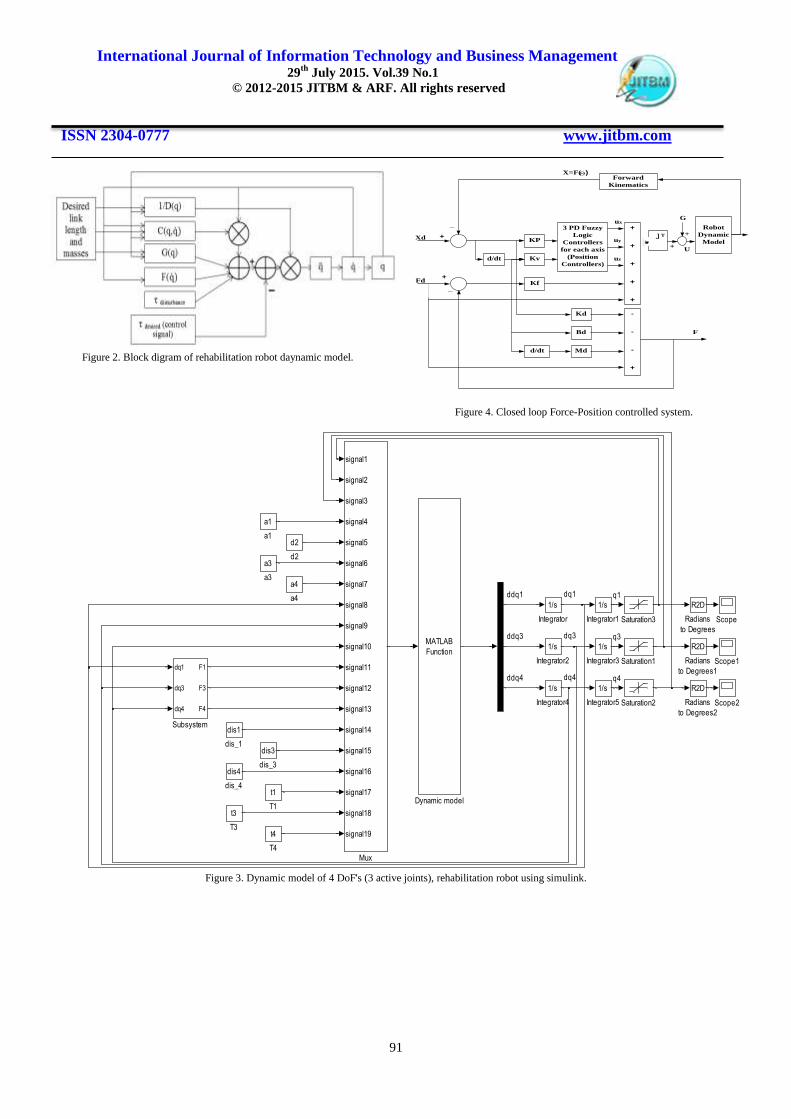
Figure 13. Second position (half ellipse) trajectory response using PSO-based
controller and without disturbance.
Figure14. Second (half ellipse) position trajectory response using
PSO-based controller with the presence of disturbance.
Figure 16. Position trajectory response of the first test.
0.16 0.18 0.2 0.22 0.24 0.26 0.28 0.3 0.32-0.7
-0.6
-0.5
-0.4
-0.3
-0.2
-0.1
0
x axis (meter)
y a
xis
(m
ete
r)
second trajectory
desired
actual
0.16 0.18 0.2 0.22 0.24 0.26 0.28 0.3 0.32-0.7
-0.6
-0.5
-0.4
-0.3
-0.2
-0.1
0
x axis (meter)
y a
xis
(m
ete
r)
second trajectory
desired
actual
0.1 0.2 0.3 0.4 0.5 0.6 0.7 0.8 0.9-0.7
-0.6
-0.5
-0.4
-0.3
-0.2
-0.1
0
z axis (meter)y a
xis
(m
ete
r)
trajectory response
actual
desired

International Journal of Information Technology and Business Management 29
th July 2015. Vol.39 No.1
© 2012-2015 JITBM & ARF. All rights reserved
ISSN 2304-0777 www.jitbm.com
96
Figure 15. Force-Position controllers with DAQ card simulink blocks.
FX
FY
FZ
0
thi4
0
thi3
0
thf4
90
thf3
100
tf
0
t
-K-
kfz
-K-
kfy
-K-
kfx
In1
In2
In3
th1
th3
th4
interfasing system
1
fzd
0
fyd
0
fxd
MATLAB
Function
forword_kinamtics
0.17
d2
MATLAB
Function
controller_equations
0.311
a4
0.341
a3
0.16
a1
zf
To Workspace4
yf
To Workspace3
zd
To Workspace2
yd
To Workspace1
t
To Workspace
Switch2
Switch1
Switch
Step2
Step1
Step
Scope9
Scope8
Scope7
Scope6
Scope34
Scope33
Scope32
Scope31
Scope30
Scope28
Scope27
Scope26
Scope25
Scope24
Scope23
Scope22
Scope21
Scope20
Scope2
Scope19
Scope18
Scope17
Scope16
Scope15
Scope14
Scope13
Scope12
Scope11
Scope10
Scope1
Scope
Saturation2
Saturation1
signal1
signal2
signal3
signal4
signal5
signal6
signal1
signal2
signal3
signal4
signal5
signal6
signal7
signal1
signal2
signal3
signal4
signal5
signal6
signal7
signal8
signal9
signal10
signal11
signal12
signal13
signal14
signal15
2
Mdz
2
Mdy
2
Mdx
Manual Switch2
Manual Switch1
Manual Switch
MATLAB
Function
MATLAB Fcn
60
KDZ
60
KDY
60
KDX
1
Gain9
0.1
Gain8
3
Gain7
3
Gain6
2
Gain5
-K-
Gain4
-K-
Gain3
5
Gain2
2
Gain14
4
Gain13
-K-
Gain12
-K-
Gain11
-K-
Gain10
-K-
Gain1
Fuzzy Logic
Controller2
Fuzzy Logic
Controller1
Fuzzy Logic
Controller
du/dt
Derivative8
du/dt
Derivative7
du/dt
Derivative6
du/dt
Derivative5
du/dt
Derivative4
du/dt
Derivative3
du/dt
Derivative2
du/dt
Derivative1
du/dt
Derivative
Demux
Demux
Demux
D2R
Degrees to
Radians6
D2R
Degrees to
Radians5
D2R
Degrees to
Radians4
D2R
Degrees to
Radians3
D2R
Degrees to
Radians2
D2R
Degrees to
Radians1
D2R
Degrees to
Radians
0
Constant5
0
Constant4
0
Constant3
0
Constant2
0
Constant1
0
Constant
0
Clock
-K-
Bdz
-K-
Bdy
-K-
Bdx
Add9
Add8
Add7
Add6
Add3
Add2
Add11
Add10
Add1

International Journal of Information Technology and Business Management 29
th July 2015. Vol.39 No.1
© 2012-2015 JITBM & ARF. All rights reserved
ISSN 2304-0777 www.jitbm.com
97
Figure 17. Position trajectory response of the second test.
Figure 18. Position trajectory response of the first test using PSO.
Figure 19. Position trajectory response of the second test using PSO.
X. REFERENCES [1] Schiele and F. C. T. Van der Helm, "Kinematic
Design to Improve Ergonomics in Human
Machine Interaction," IEEE Transactions on
Neural Systems and Rehabilitation Engineering,
Netherlands, Vol. 14, No. 4, pp. 456-469, Dec,
2006. www.ivsl.org.
[2] S. Parasuraman, A. W. Oyong and V. Ganapathy,
"Development of Robot Assisted Stroke
Rehabilitation System of Human Upper Limb,"
IEEE Conference on Automation Science and
Engineering Bangalore, India, pp. 256-261, 22-25
Aug, 2009. www.ivsl.org.
[3] J. Xianzhi, X. Caihua, S. Ronglei and X. Youlun,
"Fuzzy Hybrid Force-Position Control for the
Robotic Arm of an Upper Limb Rehabilitation
Robot Powered by Pneumatic Muscles," ICEEE
International Conference on E-Product E-Service
and E-Entertainment, Henan, pp. 1 – 4, 7-9 Nov,
2010. www.ivsl.org.
[4] J. Ueda, D. Ming, V. Krishnamoorthy, M.
Shinohara, and T. Ogasawara, "Individual Muscle
Control using an Exoskeleton Robot for Muscle
Function Testing," IEEE Transactions on Neural
Systems and Rehabilitation Engineering, Vol. 18,
No. 4, pp. 339- 350, Aug, 2011. www.ivsl.org.
[5] H. Mehdi and O. Boubaker, "Stiffness and
Impedance Control Using Lyapunov Theory for
Robot-Aided Rehabilitation," Springer
International Journal of Social Robotics,
Netherlands, Vol. 4, Issue 1 Supplement, pp. 107-
119 , 2012. www.ivsl.org.
0.1 0.2 0.3 0.4 0.5 0.6 0.7 0.8 0.9-0.7
-0.6
-0.5
-0.4
-0.3
-0.2
-0.1
0
0.1
0.2
0.3
z axis (mrtr)
y a
xis
(m
ete
r)
trajectory response
desired
actual
0.1 0.2 0.3 0.4 0.5 0.6 0.7 0.8 0.9-0.7
-0.6
-0.5
-0.4
-0.3
-0.2
-0.1
0
z axis (meter)
y a
xis
(m
ete
r)
trajectory response
actual
desired
0.1 0.2 0.3 0.4 0.5 0.6 0.7 0.8 0.9-0.7
-0.6
-0.5
-0.4
-0.3
-0.2
-0.1
0
0.1
0.2
0.3
z axis (meter)
y a
xis
(m
ete
r)
traajectory response
desired
actual

International Journal of Information Technology and Business Management 29
th July 2015. Vol.39 No.1
© 2012-2015 JITBM & ARF. All rights reserved
ISSN 2304-0777 www.jitbm.com
98
[6] M. Y. Hassan and Z. A. Karam, "Design and
Implementation of Rehabilitation Robot for
Human Arm Movements," The Second
Engineering Conference of Control, Computers and
Mechatronics Engineering, Baghdad, Iraq, 25-27
Feb, 2014.
[7] M. W. Spong, S. Hutchinson and M. Vidyasagar,
Robot Modeling and Control, John Wiley& Sons
Inc, Edition, USA, 2005.
[8] M. Arora, T. Kaur and Chetna, "Modeling of One
Link Robot Using Friction Compensator," IJCST
Vol. 2, Issue 1, pp. 216-219, March 2011.
[9] M. Y. Hassan and Z. A. Karam, "Modeling and
Force-Position Controller Design of
Rehabilitation Robot for Human Arm
Movements," Engineering & Technology Journal,
Baghdad, Iraq, Feb, 2014.
[10] Bonilla, F. Reyes, M. Mendoza, E. J. González and
Galvan, "A Dynamic-compensation Approach to
Impedance Control of Robot Manipulators,"
Springer-Journal of Intelligent & Robotic Systems,
Vol. 63, Issue 1, pp. 51-73, 2011.
[11] J. Kennedy and R. Eberhart, "Particle Swarm
Optimization," IEEE Transactions on Evolutionary
Computation, Washington, USA, pp. 1942-1948,
1995.
[12] X. Yang, J. Yuan, J. Yuan and H. Mao, "A
Modified Particle Swarm Optimizer with
Dynamic Adaptation," Elsevier -Applied
Mathematics and Computation, Vol. 189, Issue 2,
pp. 1205–1213, 15 June, 2007.
[13] M. M. Zirkohi, M. M. Fateh and M. A. Shoorehdeli,
"Type-2 Fuzzy Control for a Flexible-joint Robot
Using Voltage Control Strategy," Springer -
international Journal of Automation and Computing,
Vol. 10, Issue 3, pp. 242-255, June, 2013.
www.ivsl.org.