For the Automotive Gas Turbine Hybrid-Electric Vehicles A
12
____________________________________________________________________________________________________ EVS25 World Battery,Hybrid and Fuel Cell Electric Vehicle Symposium EVS25 Shenzhen, China, Nov 5-9, 2010 For the Automotive Gas Turbine Hybrid-Electric Vehicles A Challenge to the Virtually Zero-Emission Concepts Bogdan Thaddeus Fijalkowski Institute for Automotive Vehicles and Combustion Engines, Cracow University of Technology Krakow, Poland E-mail: [email protected] To the Living Memory of Prof. Sven-Olof Kronogård Abstract The paper describes four novels virtually zero-emission three-stage automotive gas turbine propulsion and/or dispulsion powertrains for parallel hybrid-electric vehicles. In these automotive gas turbines with oxy-fuel combustion (i.e., methane in a nearly pure oxygen environment), each including three turbine rotors operating upon independent shafts, one rotor is designed to drive the compressor or pump, one is designed to produce the main part of the power output and the third rotor is adapted to aid the two first mentioned rotors. Full-time and/or part-time exhaust gas recirculation introduces exhaust gas or liquid into the compressor’s air intake or the pump’s fluid inlet of the compressor or pump replacing some of the air or supercritical fluid, respectively. Keywords—automotive gas turbine, powertrain, exhaust gas recirculation, zero emission. ___________________________________________________________________________ 1 Introduction The potential advantages of automotive gas tur- bines (AGT) in vehicle applications captured the fancy of the technical community from the mid 1950s until the early 1970s. Enthusiasm waned when it became apparent that AGT research and development (R&D) work was not keeping up with reciprocating internal combustion engine (ICE) improvements especially in the area of fuel economy and manufacturing cost. However, the basic long-term advantages predicted for the AGT--very low emissions, light mass (high power density), multi-fuel capability, and customer appeal (smooth vibration-free power delivery) —provided sufficient incentive for further R&D work to overcome the perceived deficiencies. AGT technology has steadily advanced since its inception and continues to evolve; R&D is active in manufacturing very advanced AGTs. On the exhaust-emissions side, the challenge in AGT technology is increasing turbine inlet tempera- ture (TIT) while reducing peak flame temperature to achieve lower nitrogen oxygen (NO x ) emis- sions to cope with the latest regulations. On another front, high-power microelectronics and low-power microelectronics technology have enabled commercially viable AGTs for vehicle powertrains. During the years, a number of differ- ent AGTs have been designed for conventional automotive vehicle (CAV) applications. Each one has been aimed at better characteristics and lower price. A conventional AGT, such as the Chrysler one [1], consists of two stages (Fig. 1). Figure 1: Conventional two-stage AGT [1]. World Electric Vehicle Journal Vol. 4 - ISSN 2032-6653 - © 2010 WEVA Page000575
Transcript of For the Automotive Gas Turbine Hybrid-Electric Vehicles A

____________________________________________________________________________________________________
EVS25 World Battery,Hybrid and Fuel Cell Electric Vehicle Symposium
EVS25 Shenzhen, China, Nov 5-9, 2010
For the Automotive Gas Turbine Hybrid-Electric Vehicles
A Challenge to the Virtually Zero-Emission Concepts Bogdan Thaddeus Fijalkowski
Institute for Automotive Vehicles and Combustion Engines, Cracow University of Technology Krakow, Poland
E-mail: [email protected]
To the Living Memory of Prof. Sven-Olof Kronogård
Abstract
The paper describes four novels virtually zero-emission three-stage automotive gas turbine propulsion
and/or dispulsion powertrains for parallel hybrid-electric vehicles. In these automotive gas turbines with
oxy-fuel combustion (i.e., methane in a nearly pure oxygen environment), each including three turbine
rotors operating upon independent shafts, one rotor is designed to drive the compressor or pump, one
is designed to produce the main part of the power output and the third rotor is adapted to aid the two first
mentioned rotors. Full-time and/or part-time exhaust gas recirculation introduces exhaust gas or liquid into
the compressor’s air intake or the pump’s fluid inlet of the compressor or pump replacing some of the air
or supercritical fluid, respectively.
Keywords—automotive gas turbine, powertrain, exhaust gas recirculation, zero emission. ___________________________________________________________________________
1 Introduction The potential advantages of automotive gas tur-bines (AGT) in vehicle applications captured the fancy of the technical community from the mid 1950s until the early 1970s. Enthusiasm waned when it became apparent that AGT research and development (R&D) work was not keeping up with reciprocating internal combustion engine (ICE) improvements especially in the area of fuel economy and manufacturing cost. However, the basic long-term advantages predicted for the AGT--very low emissions, light mass (high power density), multi-fuel capability, and customer appeal (smooth vibration-free power delivery) —provided sufficient incentive for further R&D work to overcome the perceived deficiencies. AGT technology has steadily advanced since its inception and continues to evolve; R&D is active in manufacturing very advanced AGTs. On the exhaust-emissions side, the challenge in AGT
technology is increasing turbine inlet tempera-ture (TIT) while reducing peak flame temperature to achieve lower nitrogen oxygen (NOx) emis-sions to cope with the latest regulations. On another front, high-power microelectronics and low-power microelectronics technology have enabled commercially viable AGTs for vehicle powertrains. During the years, a number of differ-ent AGTs have been designed for conventional automotive vehicle (CAV) applications. Each one has been aimed at better characteristics and lower price. A conventional AGT, such as the Chrysler one [1], consists of two stages (Fig. 1).
Figure 1: Conventional two-stage AGT [1].
World Electric Vehicle Journal Vol. 4 - ISSN 2032-6653 - © 2010 WEVA Page000575

____________________________________________________________________________________________________
EVS25 World Battery,Hybrid and Fuel Cell Electric Vehicle Symposium
In the mid 1950s, Chrysler has tried two ways to propel the accessories in a two-stage AGT powertrain: from the primary turbine mechano- -mechanical (M-M) shaft (first stage) and from the power turbine M-M shaft (second stage).
In the 1970s, at United Turbine AB in Sweden, a subsidiary to Volvo AB, the Kronogård turbine transmission (KTT) system has been developed [1-3]. Professor Sven-Olof Kronogård (see Fig. 2) added a third stage. Through an original system of planetary M-M gears, the third-stage turbine supplies auxiliary power to the turbines in the first two stages [2].
Figure 2: Prof. Kronogård with his three-stage AGT
installed in a Volvo test automobile [2].
A conventional two-stage AGT dispulsion and /or dispulsion powertrain with its accessory drive on the power M-M shaft has poor torque, which brings on driveability problems. With its third turbine, the KTT three-stage AGT powertrain gets around all these difficulties [3].
For acceleration from low mechano-pneu-matical (M-P) compressor speed, the power sur-plus from the third turbine is thrown toward the M-P compressor M-M shaft. The planetary differ-ential that distributes the power flow from the auxiliary turbine also serves to adjust the speed and torque relationship between the M-P com-pressor M-M shaft and the output M-M shaft so that the output always corresponds to the vehicle requirement. This is done completely automatically and with such a fine degree of response that the need for of a conventional gearbox -- or even a torque converter -- is elimi-nated.
Ceramic turbine wheels are about 25% smaller than in other AGTs of similar power. They have less inertia, so they accelerate faster. Normally, smaller turbine wheels would mean higher angular speed to maintain power, but the KTT three-stage AGTs do not have to spin faster because they are three instead of two.
The power turbine has a maximum value of rotational speed equals 120,000 rpm. The third turbine does not just permit smaller turbine wheels. It and the associated planetary gearing allow the KTT three-stage AGT to achieve twice the stall torque possible with other AGTs.
One more thing about the third-stage turbine is that it lowers specific fuel consumption (SFC) at idle and part load--one of the big problems with other AGTs. The auxiliary M-M shaft is allowed to overrun the power M-M shaft, propelling the accessories at normal speed. Moreover, idle speed in the gasifier system can be kept lower, with less fuel being injected, because it takes less time to accelerate the lighter compression and primary turbine to maximum gas-flow velocity [3].
In the 1980s, at Cracow University of Tech-nology in Poland, propulsion and/or dispulsion powertrains termed as the KTT three-stage AGT propulsion and/or dispulsion powertrains with the Fijalkowski turbine boosting (FTB) system have been developed [4].
In the FTB system, the third-stage turbine pro-pels not only the accessories, i.e., fuel and oil mechano-fluidical (M-F) pump, etc., but a super-conductive mechano-electrical/electro-mechan-ical (M-E/E-M) generator/motor, with energy that would otherwise be wasted.
This paper deals with external combustion engine (ECE) propulsion and/or dispulsion powertrains, especially for hybrid-electric vehi-cles (HEV), which are novel virtually zero-emission (VZE) AGT and/or AGT/SOFC pro-pulsion and/or dispulsion powertrains, including transmission and auxiliary systems and, if necess-ary, solid oxide fuel cells (SOFC), and briefly compares such propulsion and/or dispulsion powertrains with reciprocating ICE counterparts.
VZE three-stage AGT/SOFC propulsion and/or dispulsion powertrains are ones in which a heat engine, such as an AGT, is combined with non-heat engine, such as an SOFC. The importance of the AGT and AGT/SOFC propulsion and/or dispulsion powertrains in overcoming some of the disadvantages of the earlier AGT propulsion powertrain is emphasized.
The paper further describes the main charac-teristics of four novel AGT and AGT/SOFC propulsion and/or dispulsion powertrains designed and investigated by the author, and underlines the substantial gains possible with such propulsion and/or dispulsion when combined with present AGT advancements, thereby making the VZE three-stage AGT and AGT/SOFC propulsion and /or dispulsion powertrains not only competetive
World Electric Vehicle Journal Vol. 4 - ISSN 2032-6653 - © 2010 WEVA Page000576

____________________________________________________________________________________________________
EVS25 World Battery,Hybrid and Fuel Cell Electric Vehicle Symposium
with, but, in several applications, superior to that of the reciprocating ICE propulsion power-trains.
In the VZE three-stage AGT or AGT/SOFC with oxy-fuel combustion, i.e., methane (CH4) in a nearly pure oxygen (O2) environment, each including two turbine rotors operating upon independent M-M shafts, one rotor is designed to drive the M-P compressor or M-F pump, one is designed to produce the main part of the power output, variable transmission means being pro-vided to interconnect the rotor M-M shafts. On the second M-M shaft is installed M-E/E-M generator/motor, which may be used not only for propulsion and/or for dispulsion of HEVs but also for cranking and or braking an M-P compressor or M-F pump.
Full-time and/or part-time exhaust gas recir-culation (EGR) introduces exhaust gas or liquid into the M-P compressor’s air intake or M-F pump’s fluid inlet of the M-P compressor or M-F pump replacing some of the air or supercritical fluid, respectively. This has the effect of reducing nitrogen oxide (NOx) emissions by reducing the in-combustor gas or liquid temperatures. NOx production is very temperature sensitive.
A recent paper has revealed some of the ele-ments of the VZE three-stage AGT propulsion and/or dispulsion powertrain concepts. These powertrains were conceived primarily for HEV applications. Special emphasis has been on re-solution of the chronic problems associated with AGTs: high-part load and idle SFC thigh cost exhaust emissions and acceleration lag.
These difficulties have discouraged and retard-ed early implementation of production programs.
The VZE three-stage AGT or AGT/SOFC ap-proach appears to have potential to resolve or mi-tigate these problems to the point where serious consideration should be given to production.
The purpose of this paper is to highlight the versatility of the VZE three-stage AGT and AGT/SOFC propulsion and/or dispulsion power-trains, to show how such one can satisfy the installation requirements of HEVs, and to indicate its potential for use in multiple AGT installations in railway applications [5].
AGT advocates have long believed that the inherent compact, light mass and smooth operat-ing characteristics of AGTs would ultimately give them an important place in HEV powertrain markets.
In 1992, Volvo built a stunning serial HEV called the environmental concept car (ECC) shown in Figure 3 [5].
Fig. 3: Volvo’s AGT-powered ECC [5]
The ECC's short 88 km (55 mi) all-electric range is admittedly limiting, but may meet the requirements of those commuting average dis-tances to the workplace. In this configuration, the ECC does meet the strict zero emission vehicle (ZEV) standard. Using the ECC's small AGT /M-E generator to power the aerial HEV's 56 kW (76 hp) E-M motor (see Fig. 4) provides a range greater than 640 km (400 mi), and at emission levels that meet California's ultra-low emission vehicle (ULEV) standard. Fig. 4: Volvo ECC's AGT/M-E generator to power
the serial HEV's E-M motor [5]
Running on AGT-generated electrical power also provides 0-96 km/h (0-60 mph) acceleration of about 13 s, much quicker than the ECC's 23 s 0-96 km/h acceleration times on CH-E/E-CH storage battery power alone [5].
With many R&D efforts, developing serial and parallel HEVs it seems at least plausible that AGT and/or AGT/SOFC powered HEVs may have a place in our future. What that place may be, and to what extent they will be used in a VZE stra-tegy, is an interesting question that has yet to be answered.
The VZE three-stage AGT and AGT/SOFC propulsion and/or dispulsion powertrains have been designed and analyzed. The important pro-blem areas have been identified and approaches to solutions formulated. They represent a new approach, which offers considerable promise for AGT powertrains.
World Electric Vehicle Journal Vol. 4 - ISSN 2032-6653 - © 2010 WEVA Page000577

____________________________________________________________________________________________________
EVS25 World Battery,Hybrid and Fuel Cell Electric Vehicle Symposium
Analysis design to date on the VZE three-stage AGT or AGT?SOFC powertrain show it to have a remarkable compatibility with the requirements for HEVs such as low idle and part load SFC, zero exhaust emissions, rapid acceleration and low cost. 2 The KTT three-stage AGT
for CAVs
In a conventional two-stage AGT (see Fig. 5a), an M-P compressor impeller draws air in and forces it through rotating heat exchangers (heated by hot exhaust gases). The heated, compressed air then passes through the combustor where fuel is continu-ously injected. Here the turbine is ignited.
The rapidly expanding gases of the burning mixture pass through the M-P compressor turbine blades and then through the power turbine blades, causing both turbine wheels to turn. Power is trans- mitted to the automotive vehicle through the power M-M shaft, through reduction M-M gears. An M-M shaft to the M-P compressor turbine connects the M-P compressor impeller, so that air is continu-ously drawn in and compressed.
KTT three-stage AGT (see Fig. 5b) works basic-ally the same, but has a third turbine wheel. This auxiliary turbine is connected to an M-M shaft that rotates independently of the second turbine M-M shaft. The auxiliary turbine feeds power (from otherwise wasted energy) back to the first and second turbines by a system of planetary M-M gears [1].
(a) ( b)
Figure 5: Conventional two-stage AGT (a) and KTT three-stage AGT (b). [1].
Schematic drawing (see Fig. 6) shows layout of turbine M-M shafts and planetary M-M gears. Whenever third turbine produces more power than is needed to propel accessories, planetary M-M differential automatically channel it to where it can do the most good [1].
The KTT three-stage AGT-powered automobile Volvo is as easy to drive as a standard one with automatic transmission--and even smoother since the AGT makes no M-M gearshifts. Starting takes a little longer, maybe five second, and in another second or so, the gasifier M-M shaft is running fast enough to enable the unit to pull under load.
To stop, a driver turns off the key and shuts off the fuel supply. The turbines coast to a halt, as a jet plane--but quietly. There are no cold-starting problems. The cooler the ambient air, the better the turbine likes it. Since it has no cooling system, it needs no antifreeze. It needs no tune- -ups, either. Ignition is needed only to get the fire started, and then it burns continuously.
Oil changes are not necessary. The AGT con-sumes a little oil and the driver simply top off the reservoir.
Professor Kronogård did not want to com-promise fuel economy in any way, but he parti-cularly wanted a very compact AGT. Moreover, that can only be obtained with the highest practical pressure ratio. The more the air is com-pressed, the less space it needs.
Three-stage AGT pressure ratios, unlike com-pression ratios, vary with its speed. Maximum pressure ratio is reached at peak compressor speed--higher-pressure ratios require higher speeds, higher strength, and materials that are more expensive.
Professor Kronogård settled for a maximum pressure ratio of 6:1, which means that at part load the KTT system is frequently working at 3 or 4:1, near the optimum for fuel economy in an AGT. The KTT three-stage AGT is calcu-lated to have a potential SFC lower than today’s stingiest diesel ICEs.
World Electric Vehicle Journal Vol. 4 - ISSN 2032-6653 - © 2010 WEVA Page000578
____________________________________________________________________________________________________
EVS25 World Battery,Hybrid and Fuel Cell Electric Vehicle Symposium
5
Why the big improvement brought about by the introduction of ceramic parts? The problem is TIT.
The hotter the gas that enters the primary turbine, the more power ones gets for each fuel droplet.
Figure 6: Layout of turbine M-M shafts and planetary M-M gears for the KTT three-stage AGT [1].
As a rule, ones get a 10% rise in power for each 311 K increase in temperature. However, ones are talking about temperatures of 311 to 1,505 K enough to soften even the most exotic metal alloys.
Ceramics such as silicon nitride and silicon carbide can withstand temperatures of 811 to 1,505 K. Stationary hot-zone ceramic parts are possible now, and they promise to come cheaply in the nearest future, but rotors are more difficult to fabricate and make survive [2].
Consequently, Professor Kronogård aims to adopt ceramic parts on a careful, piecemeal basis, while not ignoring progress made in metallurgy and metal processing.
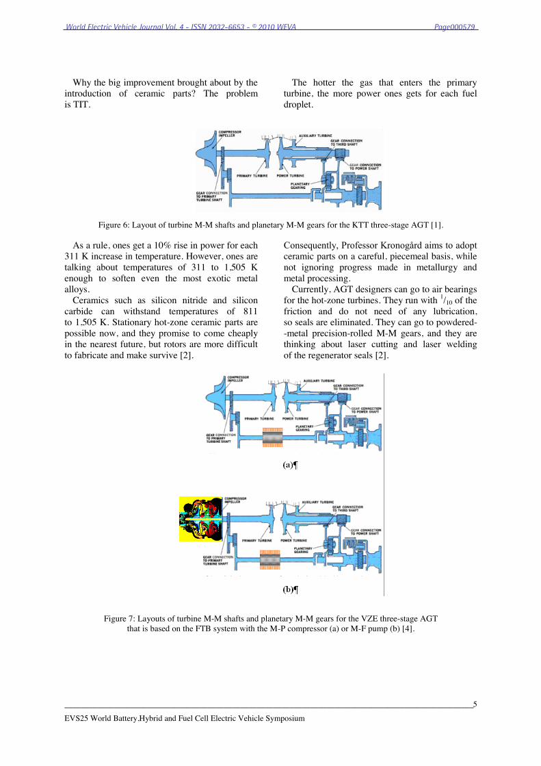
Currently, AGT designers can go to air bearings for the hot-zone turbines. They run with 1/10 of the friction and do not need of any lubrication, so seals are eliminated. They can go to powdered--metal precision-rolled M-M gears, and they are thinking about laser cutting and laser welding of the regenerator seals [2].
Figure 7: Layouts of turbine M-M shafts and planetary M-M gears for the VZE three-stage AGT that is based on the FTB system with the M-P compressor (a) or M-F pump (b) [4].
World Electric Vehicle Journal Vol. 4 - ISSN 2032-6653 - © 2010 WEVA Page000579

____________________________________________________________________________________________________
EVS25 World Battery,Hybrid and Fuel Cell Electric Vehicle Symposium
6
3 The VZE three-stage AGT for parallel HEVs
A close integration of the VZE three-stage AGT that is based on the FTB system with the parallel HEV drivetrain functions is the basic idea of the AGT propulsion and/or dispulsion powertrain. Two configurations involve three independent turbine stages (see Fig. 8).
The first stage drives the M-P compressor or M-F pump, i.e., gas-generator rotor; the second stage drives the output M-M shaft and thus the load. This is the same principle as in a conventional two-stage AGT. The third stage, the auxiliary turbine, drives a planetary-gear system, and, through this, can deliver power to both the gas-generator rotor and the output M-M shaft.
(a)
(b)
Figure 8: Layouts of turbine M-M shafts and planetary M-M gears for the VZE three-stage AGT that is based on the FTB system with the M-P compressor (a) or M-F pump (b) [4].
As the FTB system, on the third M-M shaft
is installed a superconductive M-E/E-M gen-erator/motor, which may be used for not only propulsion and/or dispulsion of HEVs but also for cranking and/or braking the M-P compressor or M-F pump (gas-generator rotor).
The newer VZE three-stage AGT that is based on the FTB system is designed as cone-shaped and installed transversally in combination with its series HEV’s super-conductive M-E/E-M gener-ator/motor (see Fig. 9) which is on the end of the M-M shaft.
It provides electric assist during acceleration and acts as an M-E generator to charge the CH-E /E-CH storage battery during braking and when the HEV is operating under AGT power.
The HEV could operate in pure electric mode up to 25 km/h. Then the VZE three-stage AGT kicks in and takes over. When you stop, the VZE three-stage AGT shuts off.
The parallel HEV’s VZE three-stage AGT that is based on the FTB system is an interesting idea, and potentially solves many of the practical problems for AGTs in automotive vehicles like start-up speed. Conversely, if the AGT are turning an M-E generator powering a chemo-electrical /electro-chemical (CH-E/E-CH) storage battery in an HEV that M-E/E-M generator/motor can also be an E-M motor--a driver could use the M-E /E-M generator/motor both as an E-M brake and M-E accelerator to improve AGT response if it were so desired.
World Electric Vehicle Journal Vol. 4 - ISSN 2032-6653 - © 2010 WEVA Page000580
____________________________________________________________________________________________________
EVS25 World Battery,Hybrid and Fuel Cell Electric Vehicle Symposium
7
For instance, the super-light lithium-polymer (LiPo) storage battery’s cells can be charged at home or at a public recharging station.
The HEV can operate on 100% storage-battery power in VZE mode for a range of up to 120 km.
When the CH-E/E-CH storage battery reaches a predetermined state of discharge, the VZE three-stage AGT quietly fires up to run the HEV’s steered, motorized and/or generatorised wheels (SM&GW) and also recharges the CH-E/E-CH storage battery on the fly to extend the driving range up to a total of around 800 km. However, even in this scenario, CH-E/E-CH storage battery losses would reduce overall efficiency quite con-siderably.
While thinking of pie-in-the-sky stuff with AGTs, another innovation on a series HEV’s VZE three-stage AGT would be a superconductive M-E /E-M generator/ motor.
Superconductors can sustain very high mag-netic fields and currents for the mass of the actual high-temperature (hT) superconducting material, especially in comparison to equivalent energy over copper conductors, and could be a serious mass advantage for a mobile widget like an HEV.
Thus, potentially designers get an AGT’s hT superconductor setup that is not only more efficient, but actually has a higher power density per kilogram [kW/kg] than an ICE alone, with no hybrid stuff even bolted on.
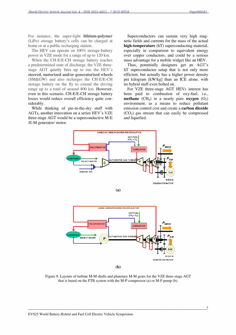
For VZE three-stage AGT HEVs interest has been paid to combustion of oxy-fuel, i.e., methane (CH4) in a nearly pure oxygen (O2) environment, as a means to reduce pollutant emission control cost and create a carbon dioxide (CO2) gas stream that can easily be compressed and liquefied.
(a)
(b)
Figure 9: Layouts of turbine M-M shafts and planetary M-M gears for the VZE three-stage AGT that is based on the FTB system with the M-P compressor (a) or M-F pump (b).
World Electric Vehicle Journal Vol. 4 - ISSN 2032-6653 - © 2010 WEVA Page000581

____________________________________________________________________________________________________
EVS25 World Battery,Hybrid and Fuel Cell Electric Vehicle Symposium
8
In most conventional combustion processes, ambient air is used as the source of O2. Nitrogen (N2) is not necessary for combustion and causes problems by reacting with O2 at combustion temperature.
A high concentration of N2 in the exhaust gas can make CO2 capture unattractive. With the current push for CO2 sequestration to ease global warming, it is imperative to develop cost-effective processes that enable CO2 capture. The use of pure O2 in the combustion process instead of ambient air eliminates the presence of N2 in the flue gas, but combustion with pure O2 results in very high temperatures. O2 at greater than 95% purity and exhaust gas recirculation (EGR) are used for oxy-fuel combustion, produc-ing exhaust gas that is mainly CO2 and water (H2O). EGR is also used to control the flame temperature and replace the volume of the missing N2 needed to carry heat through the combustor.
Combustion of oxy-fuel enriched air with CO2 recirculation is applied to optimize the O2 concen-tration, as well as the CO2 recirculation and con-centration rates.
CH4 is at the top of the hydrocarbon fuels in heat value, measured in [J/kg], and thus lends itself to scaling up.
Not including mercury and sulphur, as well as other contaminants of coal and oils, CH4 is the only one of its kind hydrocarbon fuel.
Although CH4 create about half the CO2 per unit of energy of coal, it still yields this greenhouse gas.
For VZE three-stage AGTs, CH4 is a best interim hydrocarbon fuel:
Low carbon fuel (not low enough); Mixed with H2O today to produce H2
--50% renewable fuel; Supplies not controlled by Middle East
no natural gas cartel; Two times cheaper than gasoline on en-
ergy equivalent basis; Efficiency and emissions benefits, espe-
cially in a fuel cell hybrid-electric vehi-cle (FCHV).
The oxy-fuel process proposes to increase the CO2 concentration in the exhaust gas by burning CH4 with pure O2 from an upstream laser-cryogenic air separation unit (ASU) and a cer-tain amount of recirculated exhaust gas. With oxy-fuel combustion, it is possible to achieve CO2 concentrations of above 90% in the dry exhaust gas and the liquefaction of the exhaust gas now can be managed with a relatively low energy input.
Thus, oxy-fuel combustion can be fitted to VZE three-stage AGTs. The process involves burning oxy-fuel resulting either in a concentrated exhaust gas stream of CO2, which is absorbed using solvents or absorbed onto membranes and sub-sequently captured, or even with the exhaust gas recirculated.
Ful-time and/or part-time EGR for the VZE three-stage AGT may be applied with the inten-tion of reducing CO2 emissions. When a fraction of the exhaust gas is injected in the entry of an AGT, the amount of CO2 in the exhaust gas not being recirculated will be higher and less complicated to capture. However, with this change in combustion air composition, especially the re-duced concentration of O2, the combustion pro-cess will be affected.
Full-time and/or part-time EGR introduces exhaust gas or liquid into the M-P compressor’s air intake or M-F pump’s fluid inlet of the M-P compressor or M-F pump replacing some of the air or fluid, respectively. This has the effect of re-ducing nitrogen oxide (NOx) emissions by re-ducing the in-combustor gas or liquid tempera-tures. NOx production is very temperature sensi-tive.
The oxy-fuelled VZE three-stage AGTs recircu-late exhausts gases and require less maintenance than conventional ICEs. Simple two configure-tions presented by the author from Cracow University of Technology shows the major com-ponents of the VZE three-stage AGTs that are based on the FTB system (Fig. 9).
The first-stage turbine (gas generator) expands the ambient-air and gaseous-exhaust mixture and absorbs just enough energy from the flow to drive the M-P compressor that is used for increasing the pressure of a gas (see Fig. 9a).
The first-stage turbine (gas generator) may also expands the liquid-exhaust and absorbs just enough energy from the flow to drive the M-F pump that draws a fluid into itself through an ex-trance port and forces the fluid out through an ex-haust port to the oxy-fuel combustor (see Fig. 9b).
The higher the gas-generator discharge tem-perature and pressure, the more energy is avail-able to drive the second-stage power turbine, therefore, creating second-stage work. The second -stage power turbine converts the remaining flow energy from the gas generator into useful second-stage output work. The higher the temperature difference across the power turbine, the more second-stage output power is available.
The third stage, the auxiliary turbine, drives a planetary-gear system, and, through this, can
World Electric Vehicle Journal Vol. 4 - ISSN 2032-6653 - © 2010 WEVA Page000582

____________________________________________________________________________________________________
EVS25 World Battery,Hybrid and Fuel Cell Electric Vehicle Symposium
9
deliver power to both the gas-generator rotor and the third-stage output.
The exhaust-gas system directs exhaust flow away from the AGT outlet to a condenser in EGR system. Often a silencer is part of the exhaust system. Similar to the inlet system, the exhaust-gas system is designed for minimum pressure losses.
The key feature, which contributed to removing the major problems long associated with AGTs--high SFC and scorching exhaust gas, was the regenerator or heat exchanger. It extracted heat from the hot exhaust gases, transferred this energy to the incoming air, and thus lightened the com-bustor's task of raising the gas temperature. The result was conservation of fuel as well as lower exhaust temperatures.
An AGT without a regenerator would have required several times the amount of fuel normal-ly used in a regenerator-equipped VZE three-stage AGT. The extra fuel would be required to heat the gases to operating levels.
The advantages of an AGT for HEV use include a lack of vibration, high power/mass ratio and compact size (although both aspects depend on whether a regenerator is used) and the ability to burn a variety of fuels, including those of low octane, and especially oxy-fuels. A multi-ratio gearbox is not needed--although step-down M-M gearing is.
The regenerator also performed another import-ant function. It reduced the exhaust gas tempera-ture from about 1,400 K at full AGT power to a safe level of less than 400 K.
Even more important, at idle the temperature was reduced to 350 K. By the time the gases passed through the exhaust ducts to the condenser, the temperature was reduced even to 300 K.
An exhaust gas condenser plays an important role for drying and cooling of the exhaust gas prior to compression.
However, as is clear by their lack of wide-spread use, the disadvantages are large.
The primary negatives are high cost (expensive high temperature materials needed) and high SFC. The latter is mostly the case because at part throttle, AGT is very thirsty for power being produced.
Gas flows (both intake and exhaust) are also very large, so effective filtration is bulky and ex-haust silencing needs to be comprehensive.
Emissions performance to HEV legislated stan-dards is also problematic for some AGT con-figuretions.
The VZE three-stage AGT’s powertrain, acting in parallel or series HEVs, is not only propelling or dispelling a drivetrain and generating electrical energy, but also putting out exhausted CO2 that can be sequestered or recirculated.
The lower O2 concentration decreases the stabil-ity and the increased amount of CO2, H2O and N2 will decrease the combustion temperature and thus, the NOx emissions. Adding N2 and CO2 decreases the NOx emissions, whereas O2 addition increases the NOx emissions. Addition into the fuel stream is proven to affect the NOx emissions the most. The stability limits of the flames are specified with respect to mass-based additive-to-fuel ratios. Gaseous CO2 may be injected with the ambient air (see Fig. 9a) or liquid CO2--with the fuel stream (see Fig. 9b). Liquefaction process of CO2 requires significantly less power to pump liquid than compress a gas. Advantages of oxy-fuel combustion
Exhaust gases consist of CO2 and H2O (the latter is rejected by condensation);
Very low NOx emissions; Efficient O2 separation reduces efficiency
penalty; Allowing for pure O2 for 25-30% power
saving relative to cryogenic air separa-tion;
Using O2/CO2 mixture in combustion system, raising CO2 content to 95%;
Not necessary to separate CO2 from exhaust gas;
Improvement in combustor efficiency; Reduction NOx emission; Simplification of exhaust gas treatment.
Limitations of oxy-fuel combustion Expensive air separation process with
high energy demand (cryogenic); New development of AGT necessary; CO2 recirculation for temperature con-
trol; Condensation process needs new equip-
ment. Coming back to the case of the application of EGR, VZE three-stage AGTs run not only on oxy-fuel but also on syngas (Fig. 9). This syngas consists of CH4 and CO2 and its composi-tion can be varied through a system of valves, pipes and a buffer tank. Thus, the VZE three-stage AGTs have been run on various syngas mixtures ranging from 40-100% methane. There exist some problems with combustion stability.
World Electric Vehicle Journal Vol. 4 - ISSN 2032-6653 - © 2010 WEVA Page000583

____________________________________________________________________________________________________
EVS25 World Battery,Hybrid and Fuel Cell Electric Vehicle Symposium
10
4 The VZE three-stage AGT/SOFC for parallel HEVs
The simplest VZE three-stage AGT/SOFC
cycle consists of a coupling of the two compo-nents by a recuperator (heat exchanger). In this case the SOFC exhaust heats compressed air in the AGT recuperator (Fig. 10) while anode and cathode gas preheating is done with heat from the AGT exhaust gas and the heat released from combustion of residual oxy-fuel contained in the SOFC exhaust gas. As this concept leads to high temperatures at the recuperator exit, there is only small additional firing necessary to reach the nominal TIT, pro-vided this is in the same range as the temperature of operation of the SOFC.
The high temperatures that occur in the recuper-ator require special materials, however, particular-ly high temperature alloys or expensive ceramics. There is still the need to develop inexpensive and heat-resistant materials, resulting in components with a sufficient life span. The same problem occurs at the interconnection between SOFC and recuperator. An additional problem in this area is the necessity for adapting the cooling system of the combustor (combustion chamber) walls to the elevated temperatures of the entering gas. Often the combustor is kept in operation after the introduction of the SOFC exhaust gas into the process. This is done in order to reach the maxi-mum TIT. Then the film cooling of the combustor walls has to be modified in such a way that the admissible material temperatures are met. Other-wise, also in this area new materials have tube applied.
Another possibility is to omit additional com-bustion and to accept lower TITs. With a recuper-ative combination of an SOFC and a VZE three-stage AGT an electrical efficiency of 53% is obtained, if an SOFC temperature of circa 1,223 K at a TIT of 1,193 K and a pressure ratio of 6,5 are assumed. An increase in the TIT by additional firing in the combustor of the AGT leads to a loss in efficiency apart of the oxy-fuel is only utilized in the AGT.
If the allowable TIT is below 1,200 K, the ex-haust heat of the SOFC is only partially utilized and the efficiency will decrease. This leads to the optimum of efficiency at circa 1,200 K. An in-crease in the SOFC temperature causes a mode-rate augmentation of the electrical efficiency, due to the higher operation temperature the air surplus at the cathode of the SOFC decreases.
If future development of materials technology for VZE three-stage AGT/SOFC propulsion and /or dispulsion powertrains with TITs of circa 1,800 K is assumed, this will lead to higher AGT/SOFC -- system efficiencies.
The high electrical efficiencies of AGT/SOFC -- systems integrated via recuperators increased SOFC -- operating temperatures whereas higher TITs obtained from additional firing reduce effi-ciency of this VZE three-stage AGT/SOFC pro-pulsion and/or dispulsion concept over the entire investigated range. Pressure optima of systems without additional firing are shifted to lower values. The reason for this is that additional losses due to higher-pressure ratios--particularly on the AGT side--were taken into account here. When the VZE three-stage AGT and the SOFC are coupled by a recuperator, power-to-heat ratios of unto 2.1 are realizable at a maximum SOFC — temperature of circa 1,200 K and at an exhaust temperature of circa 360 K. At SOFC operating temperatures and TITs of circa 1,300 K this coefficient increases to a value of 2.43 because of the enhanced electrical efficiency of the VZE three-stage AGT/SOFC propulsion and/or dispul-sion powertrain. A large variety of power-to-heat ratios presupposes the possibility of separate operation of the SOFC and the AGT, which can be facilitated by bypass pipes and valves. 5 Conclusions
Presented at the Paris Motor Show was the Volvo ECC. It is a fully functioning serial HEV, which uses AGT, E-M motor and high-speed M-E generator technology. Incorporating a high degree of recyclable materials, it attracts much attention in the automotive vehicle world.
So why the HEV ought to use a VZE three-stage AGT or a VZE three-stage AGT/SOFC instead of a reciprocating ICE. It turns out that there are two considerable advantages of the AGT over the ICE: VZE three-stage AGTs have a great power-to--mass ratio compared to reciprocating ICEs. That is, the amount of power getting out of the AGT compared to the mass of the ICE itself is very good. VZE three-stage AGTs are smaller than their reciprocating counterparts of the same power are. Because they spin at such high speeds and because of the high operating temperatures, designing and manufacturing VZE three-stage AGTs is a tough problem from both the engineer-ing and materials standpoint.
World Electric Vehicle Journal Vol. 4 - ISSN 2032-6653 - © 2010 WEVA Page000584

____________________________________________________________________________________________________
EVS25 World Battery,Hybrid and Fuel Cell Electric Vehicle Symposium
11
(a)
(b)
Figure 10: Layouts of turbine M-M shafts and planetary M-M gears for the VZE three-stage AGT/SOFC that is based on the FTB system with the M-P compressor (a) or M-F pump (b)
The advantages and disadvantages of the VZE
two-stage AGT or the VZE two-stage AGT/SOFC over the reciprocating ICE is, indeed, real. Some of these advantages and disadvantages are: Advantages of VZE two-stage AGTs
VZE two-stage AGT life expectancy is much longer (goes for 30-50 kh before first over-haul; usually runs for 100-300 kh (10 years) life cycle).
Fewer moving parts than reciprocating ICEs (the number of parts is reduced 80%).
Low-temperature starting difficulties are eliminated.
No warm-up period is necessary. Antifreeze is not needed. The VZE two-stage AGT will not stall
with sudden overloading.
VZE two-stage AGT operation is practic-ally vibration-free (moves in one sense of direction only, with far less vibration than a reciprocating ICE).
Exhaust gases are cool and clean as well as they can be recirculated.
Very high power-to-mass ratio, compared to reciprocating ICEs.
High operation rotational speeds. Low lubricating oil cost and consumption
(oil consumption is negligible). The VZE two-stage AGT operates at high
temperatures. The VZE two-stage AGT is compact and
easy to operate, and take advantage of automotive propulsion and dispulsion applications.
World Electric Vehicle Journal Vol. 4 - ISSN 2032-6653 - © 2010 WEVA Page000585

____________________________________________________________________________________________________
EVS25 World Battery,Hybrid and Fuel Cell Electric Vehicle Symposium
12
Disadvantages of VZE two-stage AGTs Cost is much greater than for a similar-
sized reciprocating ICE since the material must be stronger and more heat resistant; machining operations are more complex.
VZE two-stage AGT efficiency is low be-cause of the high M-P compressor or M-F pump work, and low efficiency of theirs.
The VZE two-stage AGT, without cera-mics and/or EGR, is limited by the high exhaust-gas temperature, which limits its work.
The VZE two-stage AGT without cera-mics cannot be used with ‘unclean’ fuels, because their blades can be demaged.
The novel VZE three-stage AGT propulsion and /or dispulsion powertrain overcome some of these disadvantages, and hence ought to be very popular in automotive applications. It exhibits a synergism in which the combination performs with an effi-ciency that far exceeds that which can be provided by either VZE three-stage AGT propulsion and/or dispulsion powertrain alone. Thus, the combina-tion performs better than the sum of its parts.
Use of a nearly pure oxygen instead of air in a combustor of the VZE three-stage AGT or VZE three-stage AGT/SOFC -- oxy-fuel (i.e., methane in a nearly pure oxygen environment) combustion is the least mature among the three mostly con-sidered capture technology options for the novel VZE three-stage AGT or VZE three-stage AGT/SOFC propulsion and/or dispulsion power-trains. Three key development issues:
Combustor development; Air separation unit (cost and capacity
of oxygen production); Carbon dioxide processing (removal
of impurity). The working definition of VZE three-stage
AGT/SOFC propulsion and/or dispulsion power-trains is evolving, but currently the following statement captures the basic elements: VZE three-stage AGT /SOFC propulsion and/or dispulsion powertrains combine two or more energy conver-sion devices that, when integrated provide:
Additional advantages over those devices operated individually.
A synergism that yields performance that exceeds the sum of the components.
With these attributes, combined with an inhe-rent low level of pollutant emission, VZE three-stage AGT/SOFC propulsion and/or dispulsion powertrain configurations are likely to represent a major percentage of the next generation ad-
vanced powertrains for HEVs. It appears that there are no technological barriers to preclude possible production of VZE three-stage AGT /SOFC propulsion and/or dispulsion powertrains, but there is much R&D work still ahead. The configurations of potentially competitive AGT-powered HEVs can be defined.
The technology is essentially in place, but the economic and business strategies are open ques-tions that can only be answered by the vehicle manufacturers involved. With decisions to pro-ceed and adequate funding, production could begin in three to ten years. The author is now finishing the conceptual design and first article testing stage of the VZE three-stage AGT and/or AGT/SOFC and plans to finalize a limited pro-duction plan, based in part on interest received at the EVS 25, very soon.
I look forward to continue to work together with you towards our vision of further enhancement in the novel VZE three-stage AGT and/or VZE three-stage AGT /SOFC technology.
References [1] J.P. Norbye, For the Gas Turbine Car, It’s Now or
Never. Popular Science –The What’s New Maga-zine, October 1973, pp. 56-59
[2] J.P. Norbye, Turbine with a new twist–Good bye problem with emissions, mileage, and durability? Popular Science–The What’s New Magazine, October 1979, pp. 22-27.
[3] S-O. Kronogård, Three-shaft turbine-transmission system for vehicular applications. United Turbine AB & Co, Malmö, Sweden. Fourth International Symposium on Automotive Propulsion Systems sponsored by NATO Committee on the Challenges of Modern Society. Vol. I, Washington, D.C., USA, April 17-22, 1977
[4] B.T. Fijalkowski, Very advanced propulsion auto-motive gas turbines' power boosting with low specific fuel consumption and low pollutant emis-sion capability, Proc. Autotechnologies '85: Inter-national Forum on New Automotive Technol-ogies, Monte Carlo, Monaco, 28 Jan. -- 2 Feb., pp. GT.1-GT.21
[5] R. Cogan, Volvo Hybrid Environmental Concept Car, The report reprinted just as it ran in Green Car’s February 1993 issue, SHARE, 31 October 2007, http://www.addthis.com
Author Prof. Dr. B. T. Fijalkowski was the Director of the Electrotechnics and Industrial Electronics Institute, and the Head of Mechatronics Institution at the Cracow University of Technol-ogy. He is the signatory of the MoU for the establishment of World Elec-tric Vehicles Association (WEVA).
World Electric Vehicle Journal Vol. 4 - ISSN 2032-6653 - © 2010 WEVA Page000586