
爀屲For more sample templates, click the File t對ab, … · This presentation demonstrates the...
80
Ivy Tech Community College Craig Porter Energy Center
Transcript of 爀屲For more sample templates, click the File t對ab, … · This presentation demonstrates the...

Ivy Tech Community College
Craig Porter
Energy Center
Presenter
Presentation Notes
This presentation demonstrates the new capabilities of PowerPoint and it is best viewed in Slide Show. These slides are designed to give you great ideas for the presentations you’ll create in PowerPoint 2010! For more sample templates, click the File tab, and then on the New tab, click Sample Templates.

Electrical Power

Electron Theory of Matter
Molecules are made up of even smaller particles, each of which is called an atom.

Electron Theory of Matter
Atoms, in turn, can be broken down into even smaller particles. These smaller subatomic particles are known as electrons, protons, and neutrons.
The features that make one atom different from another also determine the atom's electrical properties.

Structure of An Atom
The nucleus is located in the center of the atom. Electrons rotate in orbit around the nucleus.
Electrons are prevented from flying off into space by the attraction between the negative electron and the positive nucleus.
Electrons are prevented from being pulled into the nucleus by the force of their momentum.

Aluminum Atom
No. Protons = No. Electrons 13 = 13 Therefore, net electric charge is neutral or zero.
The particles that can be found in the nucleus are called protons and neutrons.
A proton has a positive ( +) electrical charge that is exactly equal in strength to that of the negative (– ) charge of an electron.

Energy Levels and Shells
A shell is an orbiting layer or energy level of one or more electrons.
There are a maximum number of electrons that can be contained in each shell.

Placement of Electrons in A Copper Atom
“K” Shell complete (2)
“L” Shell complete (8)
“M” Shell complete (18)
“N” Shell incomplete (1) [ Room for 31 more]
Shell K (or #1) = 2 (full) Shell L (or #2) = 8 (full) Shell M (or #3) = 18 (full) Shell N (or #4) = 1 (incomplete)

Ionization Process
Electron added
NEGATIVE ION 5 Electrons and 4 Protons Negative Charge
Electron removed
POSITIVE ION 3 Electrons and 4 Protons Positive Charge
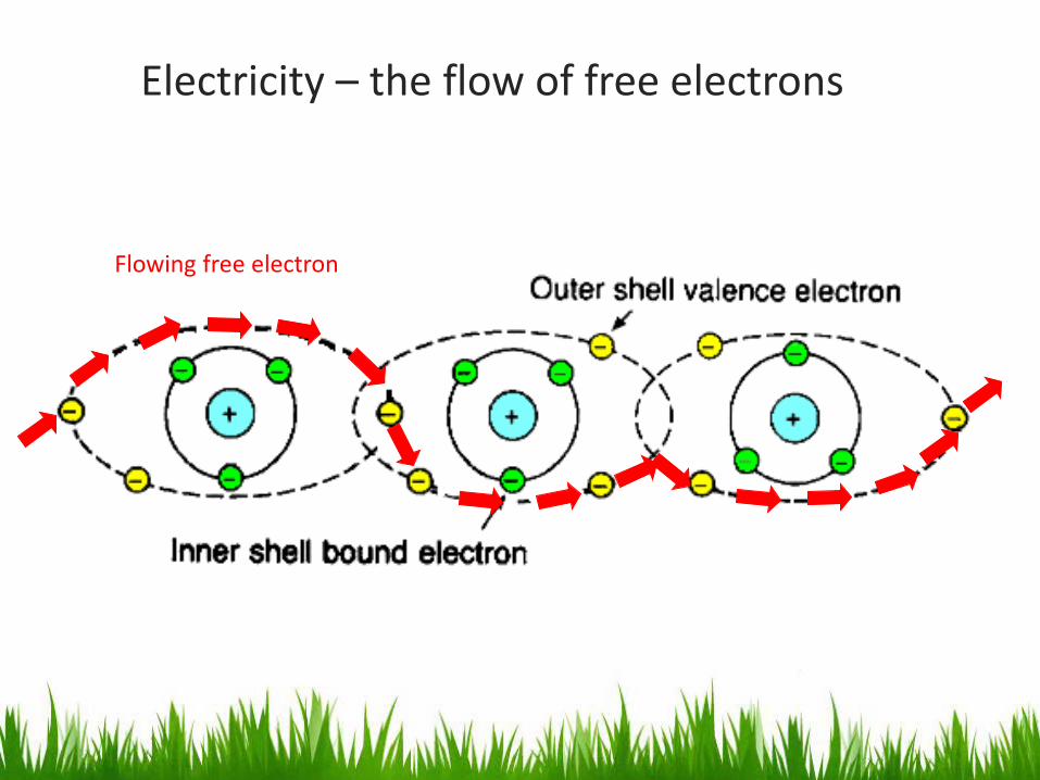
Electricity – the flow of free electrons
Flowing free electron

Energy Source
The energy source supplies the voltage required to move the free electrons along the conducting path of the circuit. It is also referred to as the power supply. Two types of sources, direct current (DC) and alternating current (AC), are used.
Battery
Electronic Power supply
Solar Panel The current flow in a circuit will always be in the same direction, if the polarity of the source always remains the same. This type of current flow is called direct current, and the source is called a direct current source. Any circuit that uses a direct-current (DC) source is then a direct-current circuit.
DC Voltage Sources

There are several types of direct current and all depend upon the value of the current in relation to time.
Direct Current (DC)
Pure or constant direct current shows no variations in value over a period of time.
Current
Time

Direct Current (DC) Pulsating or digital direct current variations are uniform and repeat at regular intervals.
Current
Time
Pulsating direct current associated with electronic DC-power supplies

AC Voltage Sources
Power Plant
Circuit Breake Panel
When voltage polarity of the power source changes, or alternates, the direction of the current flow will also alternate. This type of current flow is called alternating current, and the source is called an alternating current source. Any circuit that uses an alternating-current (AC) source is then an alternating-current circuit.

Alternating Current (AC) Alternating current changes in both value and direction.
The current increases from zero to some maximum value and then drops back to zero as it flows in one direction.
The sine wave is the most common waveform for alternating current.
This same pattern is then repeated as it flows in the opposite direction.
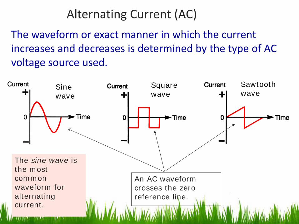
Alternating Current (AC) The waveform or exact manner in which the current increases and decreases is determined by the type of AC voltage source used.
The sine wave is the most common waveform for alternating current.
Sine wave
Square wave
Sawtooth wave
An AC waveform crosses the zero reference line.

Generator Principle
Magnetic field
If we move the conductor through the magnetic field, a force is exerted by the magnetic field on each of the free electrons within the conductor. These forces add together and the effect is that voltage is generated or induced into the conductor.
Moving conductor
Induced voltage

Induced Voltage
The amount of voltage induced in a conductor as it moves through a magnetic field depends upon:
The strength of the magnetic field; the stronger the field the more voltage induced.

Induced Voltage
The amount of voltage induced in a conductor as it moves through a magnetic field depends upon:
The angle at which the conductor cuts the flux; maximum voltage is induced when the conductor cuts the flux at 90 degrees and less voltage is induced when the angle is less than 90 degrees.

Sine Wave Frequency
The number of voltage cycles induced in the armature each second is called the frequency of the generated sine wave
The standard frequency of AC power generated in North America is 60 Hz or 60 cycles per second.

Sine Wave Frequency
The frequency of the induced voltage in each phase of a 3-phase alternator is directly related to the number of field poles of the rotor, the winding of the stator coils and to the rotational speed of the rotor.
The formulas used to determine the frequency of an AC generator are:
Frequency (F) = No. of poles (P) x Revolutions per second (S) 2
Frequency (F) = No. of poles (P) x Revolutions per minute (S) 120

Calculating Frequency
Problem What is the output frequency of an alternator with a rotor that has six poles and turns at 1000 rpm?
Solution F = PS 120 = 6 x 1000 120 = 50 Hz

Ohm’s Law

Voltage, Current, and Resistance
Three fundamental quantities-voltage, current, and resistance-are present in every electric circuit
Voltage (E) – pressure that cases the flow of electrons.
Current (I) – rate of flow of electrons.
Resistance (R) – opposition to the the flow of electrons.

Quantity Unit of Measure
Function Name Name Symbol Symbol
Electrical Units
Voltage E Voltage V Pressure which makes current flow
Current I Ampere A Rate of flow of electrons
Resistance R Ohm Ω Opposition to current flow

Ohm’s Law Formulas
Mathematically, Ohm’s law can be expressed in the form of three formulas: one basic formula and two others derived from it. Using these three formulas, and knowing any two of the values for voltage, current, or resistance, it is possible to find the third value.
Find Current Find Voltage Find Resistance
I = E / R Current equals voltage divided by resistance
E = I x R Voltage equals current multiplied by resistance
R = E / I Resistance equals voltage divided by current

Electrical Units
There are three basic measurements made on electrical circuits: voltage (E), current (I), and resistance (R).
Voltage (E)
- +
Current (I) Resistance (R)
A

= 8 A
I = E R
120 V 15 Ω
=
Applying Ohm’s Law to Calculate Current By using Ohm’s law, we can predict what is going to happen in a circuit before we apply power. When any two of the three quantities (V, I, or R) are known, the third can be calculated. For example, if the voltage and resistance are known, the current can be calculated.
E = 120 V
Heater
R = 15 Ω
I = ?

Applying Ohm’s Law to Calculate Voltage Find the voltage using ohm’s law
E = ?
R = 5 Ω
I = 2.5 A
= 2.5 A x 5 Ω
E = I x R
= 12.5 V
Solar Cell
Load
Power Formulas
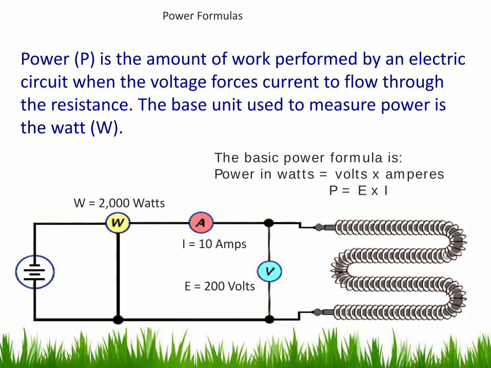
Power (P) is the amount of work performed by an electric circuit when the voltage forces current to flow through the resistance. The base unit used to measure power is the watt (W).
The basic power formula is: Power in watts = volts x amperes P = E x I
I = 10 Amps
E = 200 Volts
W = 2,000 Watts

Series Circuit

If two or more loads are connected end-to-end, they are said to be connected in series. This is called a series circuit. The same amount of current flows through each of them. Also, there is only one possible path through which the current flows.
Series Connected Loads
The current stops if this path is opened or the circuit is broken at any point. For example, if two lamps are connected in series and one burns out, both lamps will go out.

When loads are connected in series, each receives part of the applied source voltage. For example, if three identical lamps are connected in series, each will receive one-third of the applied source voltage. The amount of voltage each load in series receives is directly proportional to its electrical resistance. The higher the resistance of the load connected in series, the more voltage it receives.
Series Connected Loads

The filaments of some types of holiday tree lamps illustrate loads that are connected in series. These are of the type that if one lamp goes out, all lamps will go out. Lamps with identical resistance are used so each receives the same amount of voltage. The number of lamps connected in series determines the voltage rating of each lamp in the string. For example, in a ten string set of series connected lamps designed to operate from a 120 volt source, each lamp would require a minimum voltage rating of 12 volts (120V/10).
Series Connected Loads
120 V

Solving DC Series Circuits
In solving a DC series circuit problem, you must know the voltage, current, resistance, and power characteristics of the circuit.
They are most easily remembered by recalling the following equations for a series DC circuit: IT = I1 = I2 = I3 . . . . ET = E1 + E2 + E3 . . . . RT = R1 + R2 + R3 . . . . PT = P1 + P2 + P3 . . . .

Solving DC Series Circuits
One helpful method of solving circuits is to use a table to help organize the steps used in solving the problem. Start by recording all given values of voltage, current, resistance, and power. Next calculate the unknown values and record each in the table as they are determined.
Voltage Current Resistance PowerR1
R2
Total
E1 I1 R1 P1
E2 I2 R2 P2
ET IT RT PT

Solving DC Series Circuits
Problem: Find all the unknown values of E, I, R, and P, for the series circuit shown.

Solving DC Series Circuits
STEP 1 Make a table and record all known values.
Voltage Current Resistance PowerR1
R2
Total
12 Ω
4 Ω
24 V

Solving DC Series Circuits STEP 2 Calculate RT and enter the value in the table. RT = R1 + R2 = 12 Ω + 4 Ω = 16 Ω
Voltage Current Resistance PowerR1
R2
Total
12 Ω
4 Ω
24 V 16Ω

Solving DC Series Circuits STEP 3 Calculate IT, I1, I2 and enter the values in the table. IT = ET RT = 24 V ÷ 16 Ω = 1.5 A
Voltage Current Resistance PowerR1
R2
Total
12 Ω
4 Ω
24 V 16Ω
IT = I1 = I2 = 1.5 A
1.5 A
1.5 A
1.5 A

Solving DC Series Circuits STEP 4 Calculate E1 and E2 and enter the values in the table. E1 = I1 x R1 = 1.5 A x 12 Ω = 18 V
Voltage Current Resistance PowerR1
R2
Total
12 Ω
4 Ω
24 V 16Ω 1.5 A
1.5 A
1.5 A
E2 = I2 x R2 = 1.5 A x 4 Ω = 6 V
18 V
6 V

Solving DC Series Circuits STEP 5 Calculate PT, P1, P2 and enter the values in the table. PT = ET x IT = 24 V x 1.5 A = 36 W
Voltage Current Resistance PowerR1
R2
Total
12 Ω
4 Ω
24 V 16Ω 1.5 A
1.5 A
1.5 A
18 V
6 V
36 W
P1 = E1 x I1 = 18 V x 1.5 A = 27 W
27 W
P2 = E2 x I2 = 6 V x 1.5 A = 9 W
9 W

Parallel Circuit

Parallel-Connected Loads
If two or more loads are connected across the two voltage source leads they are said to be connected in parallel. This is called a parallel circuit.

Parallel-Connected Loads
The parallel connection of load devices is used for circuits where each device is designed to operate at the same voltage as the power supply.
Each load operates at the voltage value of the source

Parallel-Connected Loads
Home lighting and small appliance circuits are designed to operate at 120 VAC. All appliances and lights connected in parallel to these branch circuits must be rated for 120 V. The use of lower voltage devices, such as 12-V devices would cause such units to burn out. The use of higher voltage devices on these circuits, such as 240-V devices would cause such units not to operate properly.
All loads operate at 120 volts

Parallel-Connected Loads
A parallel circuit has the same amount of voltage applied to each device. However, the current to each device will vary with the resistance of the device. The amount of current each in-parallel load passes is inversely proportional to its resistance value. The higher the resistance of the load connected in parallel, the less current it passes.

Parallel-Connected Loads
When load devices are operated in parallel, each load operates independently of the others.
There are as many current paths as there are loads.

Parallel-Connected Loads
If two lamps are connected in parallel, there will be two paths created.
If one lamp burns out, the other will not be affected.
Burnt out (open)
Remains "on"

Parallel-Connected Loads
Holiday tree lamp strings wired in parallel have the advantage that if any one lamp goes out, the other lamps in the string will continue to operate.
All lamps in a parallel string are rated for 120 V regardless of the number of lamps used.

Solving DC Parallel Circuits The procedure for solving parallel-circuit values of voltage, current, resistance, and power is similar to that used for solving values for series circuits.
The parallel-circuit characteristics of voltage, current, resistance, and power. IT = I1 + I2 + I3 . .
ET = E1 = E2 = E3 . . .
PT = P1 + P2 + P3 . . .
Ohm’s law as it applies to the circuit as a whole and to individual loads, as well, is used.
I = E /R E = I x R
R = E/ I
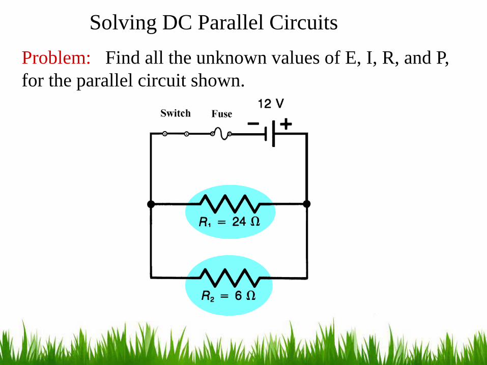
Solving DC Parallel Circuits Problem: Find all the unknown values of E, I, R, and P, for the parallel circuit shown.

Solving DC Parallel Circuits
STEP 1 Make a table and record all known values.
Voltage Current Resistance PowerR1
R2
Total
24 Ω
6 Ω 12 V

Solving DC Parallel Circuits
STEP 2 Calculate E1 and E2 enter the values in the table.
Voltage Current Resistance PowerR1
R2
Total
24 Ω
6 Ω
12 V
12 V
12 V
ET = E1 = E2 = 24 V

Solving DC Parallel Circuits STEP 3 Calculate I1, I2, IT and enter the values in the table.
IT = I1 + I2 = 0.5 A + 2 A = 2.5 A
Voltage Current Resistance PowerR1
R2
Total
24 Ω
6 Ω
12 V
12 V
12 V
I1 = E1 R1 = 12 V ÷ 24 Ω = 0.5 A
0.5 A
I2 = E2 R2 = 12 V ÷ 6 Ω = 2 A
2 A
2.5 A

Solving DC Parallel Circuits STEP 4 Calculate the value of RT and enter the value in the table.
RT = ET IT = 12 V 2.5 A = 4.8 Ω
Voltage Current Resistance PowerR1
R2
Total
24 Ω
6 Ω
12 V
12 V
12 V 0.5 A
2 A
2.5 A
RT = R1 x R2 R1 + R2 = 24Ω x 6 Ω 24Ω + 6Ω = 144 30 = 4.8 Ω
OR
4.8 Ω

Solving DC Parallel Circuits STEP 5 Calculate PT, P1, P2 and enter the values in the table.
P1 = E1 x I1 = 12 V x 0.5 A = 6 W
P2 = E2 x I2 = 12 V x 2 A = 24 W
Voltage Current Resistance PowerR1
R2
Total
24 Ω
6 Ω
12 V
12 V
12 V 0.5 A
2 A
2.5 A 4.8 Ω
PT = ET x IT = 12 V x 2.5 A = 30 W
30 W
6 W
24 W

Photovoltaic Electrical
Basics

Solar Power Basics
• Solar radiation – energy coming from the sun in the form of waves and small particles
• Solar noon – time of day when the sun is at it’s highest point in the sky
• Solar constant – energy of 1000 W/m2 at the equator at sea level at solar noon

Typical PV Module

-One amp of current flowing for 1 hour is equal to 1 amp-hour.
-Watt Hours equals the electrical power consumed multiplied by the length of time the load has been operated.
-PV Systems can be configured in Series, Parallel, or Series Parallel.
Electrical Basics

Electrical Basics-Series Configuration

Electrical Basics-Parallel Configuration

Electrical Basics-Parallel Configuration

-Blocking diodes prevent current from reversing from the battery bank and are installed in the charge controllers.
Electrical Basics

Example
Electrical Basics

The Installation of new technology “smart meters” creates an easy way for solar PV energy Systems to be connected to the utility grid. Smart Meters have the capability of measuring the electrical energy generated by a PV system, as well as the electrical energy received from the utility grid.
Electrical Basics

Charge Controllers

Charge Controllers
-Batteries used in a PV system need a charge controller to prevent over-charging and over-discharging.

Inverters Xantrex-6048

An inverter at it’s most simplistic application takes a DC voltage source, and turns it into a AC voltage source, generally 120/240 Volts at 60 hertz.
Inverters
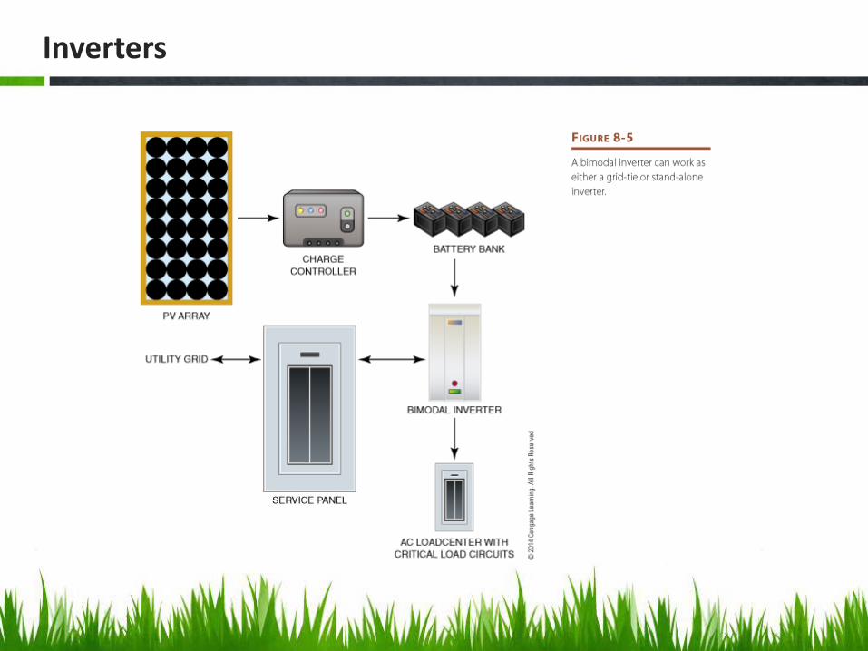
Inverters

Design

Equipment

WIND POWER

Wind Power

Utility Scale Wind Turbines

Equipment Changes
• Increased blade length

Wind Power
• TOUR THE INSIDE OF A WIND TURBINE

What’s Your Message? Be Green!


![Panther Analytics “Dean’s Story Board”...Panther Analytics “Dean’s Story Board” ... It is also the national 對sport of Bangladesh.[1]\爀屲These are the Pink Panthers](https://static.fdocuments.in/doc/165x107/5ea69575d2277605e77c9663/panther-analytics-aoedeanas-story-boarda-panther-analytics-aoedeanas-story.jpg)