Folding wrinkles of a thin stiff layer on a soft...
23
Proc. R. Soc. A (2012) 468, 932–953 doi:10.1098/rspa.2011.0567 Published online 23 November 2011 Folding wrinkles of a thin stiff layer on a soft substrate BY JEONG-YUN SUN 1 ,SHUMAN XIA 3,† ,MYOUNG-WOON MOON 2 , KYU HWAN OH 1 AND KYUNG-SUK KIM 3, * 1 Department of Materials Science and Engineering, Seoul National University, Seoul 151-742, Republic of Korea 2 Interdisciplinary Fusion Technology Division, Korea Institute of Science and Technology, Seoul 136-791, Republic of Korea 3 School of Engineering, Brown University, Providence, RI 02912, USA We present the mechanics of folding surface-layer wrinkles on a soft substrate, i.e. inter-touching of neighbouring wrinkle surfaces without forming a cusp. Upon laterally compressing a stiff layer attached on a finite-elastic substrate, certain material nonlinearities trigger a number of bifurcation processes to form multi-mode wrinkle clusters. Some of these clusters eventually develop into folded wrinkles. The first bifurcation of the multi-mode wrinkles is investigated by a perturbation analysis of the surface-layer buckling on a pre-stretched neo-Hookean substrate. The post- buckling equilibrium configurations of the wrinkles are then trailed experimentally and computationally until the wrinkles are folded. The folding process is observed at various stages of wrinkling, by sectioning 20–80 nm thick gold films deposited on a polydimethylsiloxane substrate at a stretch ratio of 2.1. Comparison between the experimental observation and the finite-element analysis shows that the Ogden model deformation of the substrate coupled with asymmetric bending of the film predicts the folding process closely. In contrast, if the bending stiffness of the film is symmetric or the substrate follows the neo-Hookean behaviour, then the wrinkles are hardly folded. The wrinkle folding is applicable to construction of long parallel nano/micro-channels and control of exposing functional surface areas. Keywords: wrinkle folding; nonlinear deformation; bifurcation; post-buckling equilibrium; gold film; PDMS 1. Introduction Wrinkles of a thin stiff layer attached on a soft substrate, ranging from bio-cellular to geological-crust wrinkles, have been observed widely in nature. The formation process of such wrinkles has recently been recognized as an attractive means of making two-dimensional self-organized patterns at multiple length scales for various applications, such as flexible electronics, optics with pitch-controllable *Author for correspondence ([email protected]). † Present address: George W. Woodruff School of Mechanical Engineering, Georgia Institute of Technology, Atlanta, GA 30332-0405, USA. Received 17 September 2011 Accepted 26 October 2011 This journal is © 2011 The Royal Society 932 on July 29, 2018 http://rspa.royalsocietypublishing.org/ Downloaded from on July 29, 2018 http://rspa.royalsocietypublishing.org/ Downloaded from on July 29, 2018 http://rspa.royalsocietypublishing.org/ Downloaded from
Transcript of Folding wrinkles of a thin stiff layer on a soft...

Proc. R. Soc. A (2012) 468, 932–953doi:10.1098/rspa.2011.0567
Published online 23 November 2011
Folding wrinkles of a thin stiff layeron a soft substrate
BY JEONG-YUN SUN1, SHUMAN XIA3,†, MYOUNG-WOON MOON2,KYU HWAN OH1 AND KYUNG-SUK KIM3,*
1Department of Materials Science and Engineering, Seoul National University,Seoul 151-742, Republic of Korea
2Interdisciplinary Fusion Technology Division, Korea Institute of Scienceand Technology, Seoul 136-791, Republic of Korea
3School of Engineering, Brown University, Providence, RI 02912, USA
We present the mechanics of folding surface-layer wrinkles on a soft substrate,i.e. inter-touching of neighbouring wrinkle surfaces without forming a cusp. Uponlaterally compressing a stiff layer attached on a finite-elastic substrate, certain materialnonlinearities trigger a number of bifurcation processes to form multi-mode wrinkleclusters. Some of these clusters eventually develop into folded wrinkles. The firstbifurcation of the multi-mode wrinkles is investigated by a perturbation analysisof the surface-layer buckling on a pre-stretched neo-Hookean substrate. The post-buckling equilibrium configurations of the wrinkles are then trailed experimentallyand computationally until the wrinkles are folded. The folding process is observedat various stages of wrinkling, by sectioning 20–80 nm thick gold films deposited ona polydimethylsiloxane substrate at a stretch ratio of 2.1. Comparison between theexperimental observation and the finite-element analysis shows that the Ogden modeldeformation of the substrate coupled with asymmetric bending of the film predicts thefolding process closely. In contrast, if the bending stiffness of the film is symmetric orthe substrate follows the neo-Hookean behaviour, then the wrinkles are hardly folded.The wrinkle folding is applicable to construction of long parallel nano/micro-channelsand control of exposing functional surface areas.
Keywords: wrinkle folding; nonlinear deformation; bifurcation; post-buckling equilibrium;gold film; PDMS
1. Introduction
Wrinkles of a thin stiff layer attached on a soft substrate, ranging from bio-cellularto geological-crust wrinkles, have been observed widely in nature. The formationprocess of such wrinkles has recently been recognized as an attractive meansof making two-dimensional self-organized patterns at multiple length scales forvarious applications, such as flexible electronics, optics with pitch-controllable
*Author for correspondence ([email protected]).†Present address: George W. Woodruff School of Mechanical Engineering, Georgia Institute ofTechnology, Atlanta, GA 30332-0405, USA.
Received 17 September 2011Accepted 26 October 2011 This journal is © 2011 The Royal Society932
on July 29, 2018http://rspa.royalsocietypublishing.org/Downloaded from on July 29, 2018http://rspa.royalsocietypublishing.org/Downloaded from on July 29, 2018http://rspa.royalsocietypublishing.org/Downloaded from

Folding wrinkles 933
gratings, and nanotechnology of adhesion, wetting and particle-sieving control(Stafford et al. 2004; Genzer & Groenewold 2006; Chan et al. 2008; Rahmawanet al. 2010). Most compression-induced wrinkles are formed by buckling of thesurface layer. In such buckling processes, very rich patterns of wrinkle clusterscan be produced by extensive material property combinations of the bi-materialsystem (Cerda & Mahadevan 2003; Efimenko et al. 2005; Moon et al. 2007).Upon further compression, some of these clusters eventually develop into foldedwrinkles, i.e. inter-touching of neighbouring wrinkle surfaces without forming acusp. This wrinkle-folding process provides a mechanical means of concealingand re-exposing partial surface areas, and can be used to construct long parallelnano- and micro-channels. To date, the mechanics of such large-amplitude foldedwrinkles and the underlying formation mechanisms are still not well understood,owing to the broad-scale nonlinear deformation characteristics entailed in thewrinkle formation process.
Historically, interest in compression-induced wrinkles was motivated by thebuckling of the sandwich panels in aircraft structures (Gough et al. 1940; Hoff &Mautner 1945). The buckling was then treated in the context of elastic stabilityby Timoshenko & Gere (1961) and of incremental elasticity by Biot (1957, 1965).Approximate structural analysis for the buckling of an elastic layer was wellsummarized by Allen (1969). The simplified structural buckling analysis wasextensively used for various applications (Röll 1976; Bowden et al. 1998; Staffordet al. 2004). A more complete analysis of elasticity for the buckling was providedby Shield et al. (1994), which presented the exact formulation of the first-orderperturbation analysis for the wrinkle formation with incrementally small-straindeformation of an isotropic substrate. A general incremental bifurcation theorythat incorporates the effects of boundary elasticity was presented by Steigmann &Ogden (1997). Lee et al. (2008) applied the bifurcation analysis for determiningthe critical load for the onset of wrinkling and the associated wavelength tosubstrates in which the elastic modulus is an arbitrary function of depth. Recently,a high-order perturbation analysis was carried out for stiff-layer wrinkles on aneo-Hookean (Rivlin 1948) elastic substrate; however, the analysis was limited toisotropic elastic perturbation with respect to the undeformed configuration of thesubstrate, and to the single-mode wrinkle deformation with vanishing interfaceshear tractions (Song et al. 2008).
While a variety of patterns have been observed under multi-axial compressionof the surface layer (Bowden et al. 1998; Chen & Hutchinson 2004; Huang et al.2005; Moon et al. 2007), an array of parallel straight wrinkles formed by uniaxialcompression are regarded as generic wrinkles. Multi-scale clustering of small-amplitude generic wrinkles has been observed experimentally on a UV-curedpolydimethylsiloxane (PDMS) substrate (Efimenko et al. 2005; Huck 2005). TheUV treatment of PDMS produces a graded distribution of elastic stiffness nearthe surface and the multi-mode wrinkles of small amplitude may be attributedto graded stiffness effect. On the other hand, a thin film layer of distinct uniformproperty on a soft substrate also produces multimode wrinkles as the amplitudegrows large. The multi-mode generic wrinkles of large amplitude are generatedby multiple bifurcations of the equilibrium wrinkle configuration. Formation ofsuch multi-mode generic wrinkles of large amplitude is needed to fold wrinkles.However, the formation of the multi-mode generic wrinkles is insufficient to foldwrinkles, and only some of the multi-mode generic wrinkles develop into folded
Proc. R. Soc. A (2012)
on July 29, 2018http://rspa.royalsocietypublishing.org/Downloaded from

934 J.-Y. Sun et al.
W
h
lpsW
lL
lW
(a)
(b)
(c)
(d)
Figure 1. Schematics of tracing the evolution of surface-layer wrinkles on a pre-stretched softsubstrate: (a) undeformed configuration of the substrate with width W ; (b) pre-stretchedconfiguration of the substrate with width lpsW ; (c) deposition of the unstrained surface layeron the pre-stretched substrate and (d) compression-induced buckling of the surface layer causedby relaxing the substrate to the stretch ratio of l; the nominal compressive strain applied on thesurface layer is 3C
L = (lps − l)/lps.
wrinkles as the amplitude grows larger. As will be shown in this paper, certainmaterial nonlinearities in large deformation kinematics are required to trigger thewrinkle folding.
Large-amplitude wrinkles of a stiff surface layer are formed on a soft substrategenerally pre-strained in finite deformation. The finite deformation of thesubstrate is highly nonlinear and induces elastic anisotropy for incrementaldeformation. The large-amplitude wrinkling often bends the surface layer beyondits elastic limit. In this paper, we address the effects of such nonlinear deformationon the wrinkle formation from its inception to final folding. Figure 1 shows aseries of schematics for the wrinkling process of an initially un-stressed thin stifflayer on a pre-stretched soft substrate. In these schematics, a long strip of a softpolymeric (PDMS) substrate of width W (figure 1a) is pre-stretched in the widthdirection to a stretch ratio lps (figure 1b) in plane-strain deformation. The pre-stretching is followed by deposition of a thin metallic (gold) film of thickness hon the surface (figure 1c). Then, the substrate is released to a stretch ratio ofl < lps, inducing thin film buckling to form post-buckling wrinkles (figure 1d). Inour experimental study reported in §3, we measure the wavelengths and shapes ofthe wrinkle patterns, at various levels of l, with atomic force microscope (AFM)topography and scanning electron microscope (SEM) imaging of the wrinkle crosssections exposed by focused ion beam (FIB) sectioning. In the experiment, weemploy the notion of nominal compressive strain 3C
L = (lps − l)/lps applied to thesurface layer by variation of the substrate stretch from the pre-stretch lps to areleased state of stretch l.
Proc. R. Soc. A (2012)
on July 29, 2018http://rspa.royalsocietypublishing.org/Downloaded from

Folding wrinkles 935
2. Bifurcation of a generic wrinkle on a neo-Hookean substrate
Buckling of a thin stiff layer on a pre-stretched soft substrate is analysed in thissection. We show how eigenmodes of the substrate deformation are involved inbuckling the surface layer under compression to form bifurcated wrinkle patternswith two different wavelengths, and how the bifurcated states evolve as thefilm is further compressed by shrinking the pre-stretched substrate. The softsubstrate is typically made of a non-porous rubbery material such as PDMS whichexhibits characteristics of incompressible finite deformation at room temperature(Yoo et al. 2006). The nature of such incompressible finite deformation is wellepitomized by the neo-Hookean constitutive relation (Rivlin 1948), for example,for uniaxial tension of a typical PDMS in the range of stretch ratio from 0.7 to1.5. The eigenmodes of perturbed substrate deformations in a uniformly stretchedneo-Hookean nonlinear finite deformation are analysed first in the following.
(a) Analysis of the substrate deformation
We consider a plane-strain deformation of the substrate for the half spaceof −∞ < X1 < ∞ and −∞ < X2 ≤ 0 in which vertical surface displacement isperturbed by dL cos kX1 on a pre-stretched configuration of lateral stretchvx1/vX1 = l and vertical stretch vx2/vX2 = 1/l. Here, the wrinkle wave numberk = 2p/L and the perturbation amplitude parameter d � 1 are employed with Lthe undeformed-configurational wavelength of the perturbation. Then, the genericform of the mapping of the configuration x2(X1, X2) is assumed to be
x2 = X2
l+ dL cos kX1eakX2 , (2.1)
where a > 0 is a parameter to be determined from the equilibrium condition. Theincompressibility condition, up to O(d2), requires the mapping x1(X1, X2) as
x1 = lX1 − adl2L sin kX1eakX2 . (2.2)
Here, we assume these functional forms of perturbation since the finite pre-stretching of the substrate generates an incrementally anisotropic elastic state(Steigmann & Ogden 1997) and the anisotropic linear elastic field in a two-dimensional half space loaded by a sinusoidal traction can be expressed bysuperposition of two elastic fields that are the same as the assumed perturbationfields with two distinct a values (A. C. Pipkin 1978, unpublished data). Further-more, as the hydrostatic pressure for incompressible neo-Hookean solids hasto be determined independently from the deformation kinematics, the pressuredistribution is assumed to be
p = p0 + dp1 cos kX1eakX2 (2.3)
with p0 and p1 to be determined from boundary conditions.The first Piola–Kirchhoff stress is given by
Tij = JF−1ik skj = QFT
ij − pF−1ij , (2.4a)
for the incompressible neo-Hookean deformation energy potential of
UN−H = Q(l21 + l2
2 + l23 − 3), (2.4b)
Proc. R. Soc. A (2012)
on July 29, 2018http://rspa.royalsocietypublishing.org/Downloaded from

936 J.-Y. Sun et al.
where li are the principal stretches, Q = E0/3 with E0 the elastic modulus ofthe neo-Hookean solid at li = 1, Fij = vxi/vXj the deformation gradient, and theJacobian J = det[Fij ] = 1 for incompressibility. Then, the deformation gradientobtained explicitly from (2.1) and (2.2) is inserted into (2.4a) to have
T11 =(
Ql − p01l
)− d
{Qkal2L + p0kaL + p1
l
}cos kX1eakX2 + O(d2), (2.5a)
T12 = −d(QkL + p0ka2l2L) sin kX1eakX2 + O(d2), (2.5b)
T21 = −d(Qka2l2L + p0kL) sin kX1eakX2 + O(d2) and (2.5c)
T22 =(
Ql
− p0l
)+ d(QkaL + p0kal2L − lp1) cos kX1eakX2 + O(d2). (2.5d)
The zeroth order (d = 0) solution is then obtained from (2.5) and T 022 = 0 as
p0 = Q/l2 and
T (0)11 = Q
(l − 1
l3
). (2.6)
With the above stress representations, the equilibrium equations up to the firstorder are expressed as
T11,1 + T21,2 ={2pQal2(1 − a2) + p1
l
}dk sin kX1eakX2 + O(d2) = 0 (2.7a)
and
T12,1 + T22,2 = (−2pQ + 2pQa2 − lap1)dk cos kX1eakX2 + O(d2) = 0. (2.7b)
Then, equation (2.7) implies an eigenvalue problem of a as[al2(1 − a2) 1/l
(a2 − 1) −la
] [2pQp1
]=
[O(d)O(d)
]. (2.8)
The positive eigenvalues, a = 1 and 1/l2, of equation (2.8) for non-divergingsolution and the corresponding eigenvector solutions provide p1 = 0 and p1 =2p(1/l4 − 1)lQ, respectively. The two distinct eigenvalues, for l �= 1, stand fortwo distinct eigenstates of the perturbed deformation on the incrementallyanisotropic elastic state generated by the pre-stretched finite deformation. Inneo-Hookean solids the incremental modulus softens in the stretching directionwhile it stiffens in the shrinking direction. For the degenerate case of l = 1, thetwo eigenstates are rearranged by lima→1(eakX2 , veakX2/va) to those of decayingin −X2 direction with ekX2 and X2ekX2 , respectively, which have been used inconventional analysis of isotropic linear elasticity (A. C. Pipkin 1978, unpublisheddata). The two eigensolutions provide the first-order functional forms of the firstPiola–Kirchhoff stress components as
T (1)11
Q=
(l − 1
l3
)− 2pd
{A
(l2 + 1
l2
)ekX2 + 2B
l4ekX2/l2
}cos kX1, (2.9a)
T (1)12
Q= −2pd
{2AekX2 + B
(1 + 1
l4
)ekX2/l2
}sin kX1, (2.9b)
Proc. R. Soc. A (2012)
on July 29, 2018http://rspa.royalsocietypublishing.org/Downloaded from

Folding wrinkles 937
T (1)21
Q= −2pd
{A
(1l2
+ l2)
ekX2 + 2Bl2
ekX2/l2}
sin kX1 and (2.9c)
T (1)22
Q= 2pd
{2AekX2 + B
(1l2
+ l2)
ekX2/l2}
cos kX1, (2.9d)
where A and B are coefficients to be determined by the boundary conditionsat the interface between the surface layer and the substrate. The Cauchystress components sij = J −1FikTkj , then, provide the expression of the tractioncomponents at the interface as
s(1)21 (x1, 0)
Q= −2pd
{2lA +
(l + 1
l3
)B
}sin
kx1
l(2.10a)
and
s(1)22 (x1, 0)
Q= 2pd
{2Al
+(
1l3
+ l
)B
}cos
kx1
l. (2.10b)
Corresponding displacement components are obtained from (2.1), (2.2) and(2.8) as
u(1)1 (x1, 0) = −(Al2 + B)dL sin
kx1
l(2.11a)
and
u(1)2 (x1, 0) = (A + B)dL cos
kx1
l. (2.11b)
(b) Plate-theory analysis of the surface-layer deformation
The expressions for the tractions and the displacements at the interfacein (2.10) and (2.11) have to be compatible with the deformation of the surfacelayer. Although the compatibility relationship can be expressed exactly up to theaccuracy of the linear elastic description of the layer deformation (Shield et al.1994), the simple theory of plate stretching and bending with single-axis curvatureis accurate enough and more conveniently applicable to layer deformations ofasymmetric bending to be discussed in the following sections. The compatibilityrelationships of the interface tractions and displacements with respect to thelinearized layer deformation consistent with the first-order perturbation of thesubstrate deformation are expressed as (Shield et al. 1994):
ELh(1 − n2
L)
(h2
3v4u(1)
2 (x1, 0)vx4
1
− h2
v3u(1)1 (x1, 0)vx3
1
+ 3CL
v2u(1)2 (x1, 0)vx2
1
)+ s
(1)22 (x1, 0) = 0
(2.12a)
Proc. R. Soc. A (2012)
on July 29, 2018http://rspa.royalsocietypublishing.org/Downloaded from

938 J.-Y. Sun et al.
and
ELh(1 − n2
L)
(v2u(1)
1 (x1, 0)vx2
1
− h2
v3u(1)2 (x1, 0)vx3
1
)− s
(1)21 (x1, 0) = 0, (2.12b)
where 3CL is the cross-sectional average strain of axial compression in the layer, and
EL the Young’s modulus and nL the Poisson’s ratio of the surface layer. Then,as (2.10) and (2.11) are inserted into (2.12), we will have a highly nonlineareigenvalue problem of the normalized wave number k̄ for buckling as⎡
⎢⎢⎣k̄3
3l4− k̄2
2l− 3C
L k̄l2
+ 2Q̂l
k̄3
3l4− k̄2
2l3− 3C
L k̄l2
+(
1l3
+ l
)Q̂
k̄ − 12
k̄2
l3+ 2lQ̂
k̄l2
− 12
k̄2
l3+
(l + 1
l3
)Q̂
⎤⎥⎥⎦
[AB
]=
[00
](2.13)
with k̄ = 2p/(L/h) and Q̂ = Q(1 − n2L)/EL, where the characteristic equation gives
the buckling strain 3B
3CL → 3B =
lk̄4 + 4(1 + l2)Q̂k̄3 + 6l(1 − l2)2Q̂k̄2
+12l4(1 + l2)Q̂k̄ + 24l3(1 + l4)Q̂2
12l2k̄{lk̄ + (1 + l2)Q̂} . (2.14)
Since the stretch ratio l of the substrate and the stiffness ratio Q̂ between thelayer and the substrate are positive, all the coefficients of the k̄ polynomialsin the numerator of (2.14) are also positive, and thus the numerator is amonotonically increasing fourth-order positive polynomial function of k̄, for0 < k̄. The denominator of (2.14) makes 3B singular at k̄ = 0 and −(1 + l2)Q̂/l,having a single positive minimum in the domain of 0 < k̄. The minimum 3B isthe compressive strain at the onset of buckling, 3cr
B , and the corresponding k̄B
determines the onset wave number of the wrinkle k̄crB . By making the derivative
of (2.14) with respect to k̄ vanish, i.e.
2l2
Q̂3(1 + l2)k̄5 + 7l
Q̂2k̄4 + 8(1 + l2)
Q̂k̄3 − 6l
Q̂2
[2l4 + (l2 − 1)Q̂
]k̄2
− 48l4(1 + l4)
Q̂(1 + l2)k̄ − 24l3(1 + l4) = 0,
(2.15)
we have the unique positive root of (2.15) as the critical buckling (minimum)wave number k̄cr
B .Figure 2a shows plots of (2.15) for the substrate stretch ratio l at which the
surface layer critically buckles with the wave number k̄crB for various stiffness-ratio
Q̂ values. Equations (2.14) and (2.15) asymptotically converges, for a very highstiffness surface layer on a very soft substrate, to
3crB → 3
2
{(1 + l2)2Q̂2
6
}1/3
for Q̂ � 1 (2.16a)
Proc. R. Soc. A (2012)
on July 29, 2018http://rspa.royalsocietypublishing.org/Downloaded from

Folding wrinkles 939
5(a)
(b)
4
3
2
1
0
1000
800
600
400
200
00 0.001 0.002 0.003 0.004 0.005
0 0.2
normalized critical buckling wave number,
nominal compressive strain,
0.4
stre
tch
ratio
of
the
subs
trat
e, l
wav
elen
gth
in d
efor
med
con
figu
ratio
n, L
* /h
0.6 0.8 1.0
Q1 = 0.00001Q2 = 0.0001
Q3 = 0.001
Q4 = 0.01
Q5 = 0.1
Q = 0.15 MPa
Q = 6.8 × 10⁻⁶
EL = 20 GPa v = 0.3
lps = 1.5
ˆˆ
ˆ
ˆ
ˆ
ˆ
¯kcrB
eCL � (lps − l))lps
Figure 2. Buckling points and the first-order perturbation prediction of wrinkle wavelengths ofa stiff thin surface layer on a stretched neo-Hookean substrate: (a) the substrate stretch ratiol at which the surface layer critically buckles with the normalized wave number k̄cr
B for variousstiffness-ratio Q̂ values; (b) solid curve: the first-order-predicted wavelengths of the post-bucklingwrinkles, measured in deformed configurations, with respect to the nominal compressive strain3CL = (lps − l)/lps applied on the surface layer; dotted curve: trace of the critical buckling points
on the stretched substrate.
Proc. R. Soc. A (2012)
on July 29, 2018http://rspa.royalsocietypublishing.org/Downloaded from

940 J.-Y. Sun et al.
and
k̄crB → l{6(1 + l2)Q̂} 1
3 forQ̂ � 1. (2.16b)
Equations (2.16a) and (2.16b) show that the critical compressive strain 3crB for the
surface layer to be critically buckled at the stretch ratio l of the substrate scaleswith {(1 + l2)/2}2/3, and the wavelength in the deformed configuration (L∗ = lL)of the wrinkle with {(1 + l2)/2}−1/3. As an example, the roots of equations (2.14)(solid line) and (2.15) (dashed line) are plotted in figure 2b for elastic buckling ofa porous gold film with nominal Young’s modulus of 20 GPa and Poisson’s ratioof 0.3, attached on a PDMS substrate. Since we use PDMS in our experiment,the deformation characteristics of which is close to those of the neo-Hookeansolid with Q = 0.15 MPa approximately up to l = 1.5, we plot the wavelengthL∗ in the deformed configuration as a function of the nominal compressivestrain 3C
L = (lps − l)/lps near the buckling point. The dashed line shows the rootsof (2.15), which stands for the trace of the critical buckling points for different l.The critical buckling wavelength looks constant in figure 2b; however, it is slightlyincreasing for decreasing l (or increasing 3C
L = (lps − l)/lps). On the other hand,the solid curve indicates the roots of (2.14), meaning the trajectory of the bucklingwavelength versus the nominal compressive strain during release of the substratestrain from the prestretched state of lps = 1.5. As shown by the solid curve, thebuckling state bifurcates beyond the critical nominal compressive strain of 0.065per cent. The wavelength of the primary buckling mode decreases as the nominalcompressive strain increases, while the long wavelength of the secondary bucklingmode grows rapidly as the compressive strain increases. As the wavelength of thesecondary mode diverges so quickly that most of the laboratory observations ina single microscopic scale are limited to the primary buckling mode. However, anobservation of the bifurcation phenomenon in computational simulation of a thinlayer buckling on a neo-Hookean solid substrate was reported by Efimenko et al.(2005) and Huck (2005). Such a bifurcation was also observed in experimentsby Shield et al. (1994). As shown in figure 2b, the wavelength of the primarywrinkle quickly reduces as soon as the layer buckles and strains a little furtherwithin a fraction of the critical compressive strain. Therefore, the measurementof the critical buckling wavelength may not be accurate, if we rely only ondirect experimental observations in using (2.16b) to measure the stiffness of asurface layer. However, the prediction of the post-buckling wavelength by thefirst-order perturbation has limited accuracy beyond the buckling point. High-order perturbation analysis is expected to improve the accuracy of the evaluationof the post-buckling wavelength. In the following sections, evolution of the post-buckling large-amplitude wrinkles towards folding is investigated by the hybridmethod of experiment and finite-element analysis.
3. Experiments on evolution of large-amplitude wrinkles
The post-buckling wrinkle patterns were generated experimentally in a thin goldfilm attached on a PDMS substrate by the following procedures. We prepared thePDMS by mixing dimethylsiloxane monomers with Sylgrad 184 silicone elastomercuring agent in a weight ratio of 15 : 1, followed by degassing in a vacuum chamber
Proc. R. Soc. A (2012)
on July 29, 2018http://rspa.royalsocietypublishing.org/Downloaded from

Folding wrinkles 941
and curing at 80◦C over 1 h. The PDMS samples were prepared in the size of40.0 × 10.0 × 3.0 mm. As depicted in figure 1b, the PDMS sample was pre-stretched to lps = 2.1, using a screw-driven tensile device which could applythe nominal compressive strain, 3C
L = (lps − l)/lps, more than 50 per cent inthe resolution of 0.5 per cent. The gold film was then ion-coated on the pre-strained PDMS using a plasma-ion coater (IB-3, Eiko) with 6 mA current, asillustrated in figure 1c. The transmission electron microscope (TEM) imageshown in figure 5a reveals that the gold film was porous in the nanometre scaleand the grain size was in the range 10–20 nm. In our experiments, we usedsamples with various film thicknesses ranging from 20 to 80 nm. The gold filmcoated on the pre-stretched PDMS was compressed as the pre-stretched strain wasrelaxed, generating periodic wrinkles grooved perpendicular to the compressiondirection. The wrinkled morphology was observed and measured in situ withoptical and AFM (Digital Instrument), while the pre-stretch of the PDMS wasreleased, as shown in figure 1d. After the pre-stretch was completely released,the PDMS was re-stretched back to the original pre-stretch, during which thegold film returns to the strain-free state. While the gold film was compressed andthe amplitude of the wrinkles grew, the cross-sectional shapes of the wrinkleswere observed by sectioning the film with FIB (NOVA200, FEI) milling. Thecross-sectional shapes were recorded by the high-resolution scanning electronmicroscope (HR-SEM) built in the FIB-system, at four different stages of thenominal compressive strains, 12, 35, 41 and 46 per cent. Before being sectionedby the FIB, the surface of the wrinkled thin film was pre-coated with carbon inthe thickness range 200–500 nm, followed by a platinum coating of 500–2500 nmthickness to hold the shape of the wrinkle from relaxation and to prevent potentialdamages of the film from gallium ion irradiation.
(a) Observations on evolution of multi-mode wrinkles
The optical-image sequence (a1)–(a6) in figure 3 shows evolving wrinklesof a 66 nm thick gold film during a compression–decompression cycle. As thepre-stretch of the PDMS was released a wrinkle pattern emerged as shown in(a2), implying that the film already buckled at a nominal compressive strain3CL less than 0.5 per cent. Non-uniformity of the wrinkles in (a2) indicates
that nucleation sites of buckling were randomly distributed and incoherentphases of the buckles were merging together at the small nominal compressivestrain, presumably owing to fluctuations of the structural properties such as filmthickness, roughness of the substrate and variations of the stiffness of the filmand the substrate. Once the nominal compressive strain was increased to 7 percent, all the pitches of the wrinkles were coherently aligned as shown in (a3). Atthis nominal compressive strain two bifurcated modes of wrinkles were observed;the primary-mode wrinkles of 2.5 mm wavelength were nested in the envelopingsecondary-mode wrinkles of 30–40 mm wavelength. Such bifurcation was predictedby the analysis in §2, and also observed experimentally and in computationalsimulations by Huck (2005) and Efimenko et al. (2005). The aspect ratio of thePDMS substrate width in stretching direction to its lateral span was too largeto produce plane-strain deformation, and the Poisson expansion of the 7 percent compression cracked the film at some places (not shown in the frame). In(a4), the compressive strain was 40 per cent and the primary-mode wrinkles
Proc. R. Soc. A (2012)
on July 29, 2018http://rspa.royalsocietypublishing.org/Downloaded from

942 J.-Y. Sun et al.
Au
5 µm
(a1)
(a2)
(a3)
(a4)
(a5)
(a6)
(b1) (b2) (b3)
prestretched PDMS
0.4
0 1 2 3 4
0.4
0 1 2 3 4 5
0.4
0 2 4 6 8 10
Figure 3. Post-buckling wrinkle evolution of a 66 nm thick gold film attached on a PDMSsubstrate initially pre-stretched to lps = 2.1 (optical micrographs): (a1) flat film at 3C
L = 0 (i.e.substrate l = lps); (a2) wrinkles at 3C
L = 0.005; (a3) primary (small wavelength) and secondary(long wavelength) wrinkles at 3C
L = 0.07; (a4) doubly paired primary wrinkles at 3CL = 0.40;
(a5) quadruply paired primary wrinkles at 3CL = 0.50; (a6) plastically deformed residual wrinkles at
3CL = 0: AFM topography of paired gold film wrinkles with (b1) 23, (b2) 30 and (b3) 44 nm thickness,
respectively, on a PDMS substrate at 3CL = 0.40 − 0.50 (units of the inset scales are in mm).
of a single-period evolved into paired wrinkles of dual period. As the film wasfurther compressed to 50 per cent, secondary pairing of paired wrinkles occurred,activating the quadruple-wavelength mode as shown in (a5). After this point, thecompression of the film was released by re-stretching the PDMS substrate. When
Proc. R. Soc. A (2012)
on July 29, 2018http://rspa.royalsocietypublishing.org/Downloaded from
Folding wrinkles 943
(i)(a) (b) 12
10
8
wav
elen
gth
(mm
)
6
4
2
0 10 20 30 40 50 60
PtC
AuPDMS
(ii)
(iii)
(iv)
single-period mode
dual-period mode
quad-period modeCLL* L(1–e )
5 mm nominal compressive strain (%), eCL � (lps − l))lps
Figure 4. Folding of wrinkles: (a) SEM images of the FIB-sectioned wrinkle cross sections at(i) 3C
L = 0.12, (ii) 3CL = 0.35, (iii) 3C
L = 0.41 (wrinkle folding) and (iv) 3CL = 0.46 (partial unfolding),
of a 74 nm thickness gold film; (b) variation of the wrinkle wavelength with respect to the appliedcompressive strain in the film of 74 nm thickness; the wavelength of the primary wrinkle varieswith L∗ = L(1 − 3C
L ), implying wavelength locking in the undeformed configuration, caused byplastic bending.
the applied compression was completely removed, the film was not fully recoveredto its original flatness. Instead, plastically deformed wrinkle patterns remainedas shown in (a6). The plastically deformed wrinkle patterns could not be totallyremoved even after the film was further stretched to 10 per cent tensile strain.
The three frames of figure 3(b1), (b2) and (b3) show triple, double andquadruple wrinkle pairs observed in gold films of 23, 30 and 44 nm thicknesses,respectively, at nominal compressive strains in the range 40–50%. In the in situAFM measurements of wrinkle topography for a 30 nm thick gold film, a single-period wavy pattern of 1.3 mm wavelength was distinctly observed at 5 per centcompressive strain, while the paired wrinkles of dual period emerged at 41 percent compressive strain. Fast Fourier transformation of the AFM topographyshowed a clear spectrum split of the wavelength into 0.9 and 1.8 mm for thepaired wrinkles. At this point, the total arc length of the wrinkle measuredby the AFM topography was reduced substantially. The reduction of the AFM-traced arc length implied folding of the wrinkle which did not allow access of theAFM tip to trace the arc length at the folded region. This observation promptedus to section-wrinkled films with FIB at different stages of compression. Uponcomplete removal of the applied nominal compressive strain in the film, theresidual deformation of the paired wavy pattern remained permanently owingto irreversible plastic deformation.
Figure 4a shows the cross-sectional shapes of a buckled gold film of 74 nmthickness cut along the loading axis by FIB at four different places for fourdifferent levels of the nominal compressive strain (12, 35, 41 and 46%). Theexposed cross sections were imaged by SEM at an angle of 38◦ tilt with respectto the normal of the cross-section, towards the surface normal of the undeformedPDMS substrate. Therefore, actual amplitudes of the wrinkles are larger than
Proc. R. Soc. A (2012)
on July 29, 2018http://rspa.royalsocietypublishing.org/Downloaded from
944 J.-Y. Sun et al.
Pt
carbon
PDMS
M
M–
M+
O k
0.05 mm
1.6uniaxial testsecond-order Ogden modelneo-Hookean model
1.4
1.2
1.0
0.8
0.6
0.4
0.2
0.2 0.4 0.6nominal strain
nom
inal
str
ess
(MPa
)
0.8 1.0 1.20
gold
(a)
(b) (c)
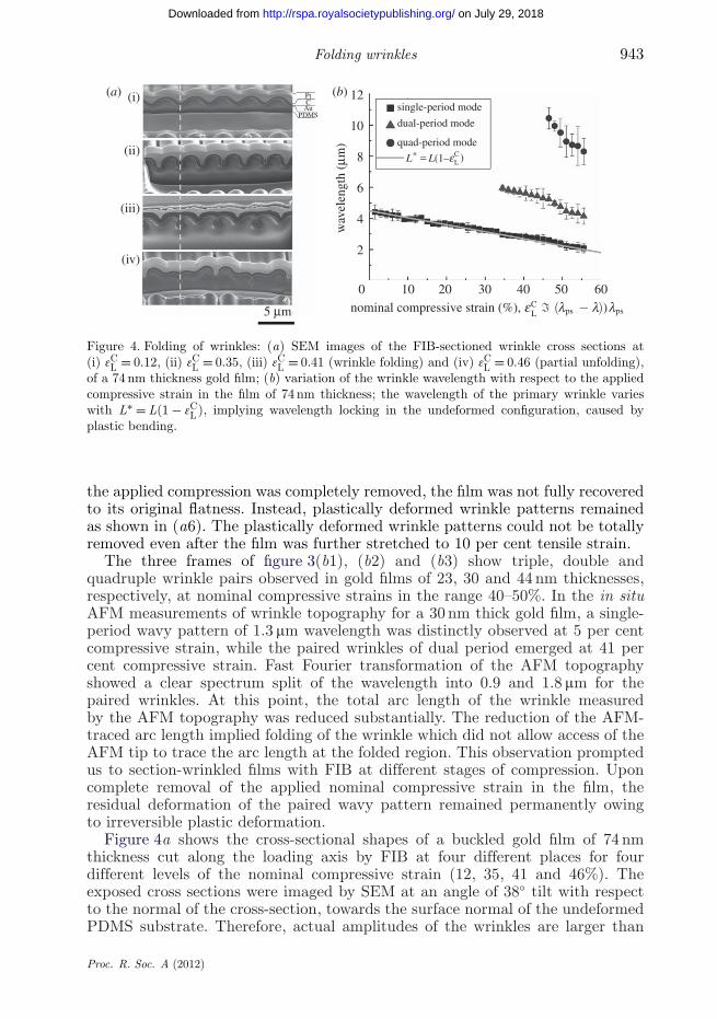
Figure 5. (a) An S-TEM image of the cross section of a 50 nm thickness gold film showing anasymmetric distribution of grain grooves, which creates asymmetric bending stiffness of the film.(b) A schematic of the relationship between bending moment and curvature of the thin gold film.(c) Experimentally measured nominal stress–strain curve of the PDMS substrate.
those shown in the figure by factor of 1/cos 38◦. As shown in (i) of figure 4a,the primary wrinkle at the nominal compressive strain of 12 per cent exhibitssingle-period waviness. However, the curvature at the valley of the wrinkle isconsiderably larger than that at the peak, insinuating that the film might haveasymmetric bending stiffness. This observation brought us about imaging thecross-sectional configuration of the nano-grains in the gold film with a TEM,which is shown later in figure 5a. As the compressive strain reached 35 per cent,the curvature contrast was even enhanced as shown in (ii), and repeated pairsof the wrinkles begin to bunch, activating the paired wrinkle pattern of dualperiod. A close look reveals that the platinum coating layer applied prior to FIBsectioning was cracked open in every other valley of the wrinkle. Implication
Proc. R. Soc. A (2012)
on July 29, 2018http://rspa.royalsocietypublishing.org/Downloaded from

Folding wrinkles 945
of this phenomenon will be treated in §4 in comparison with computationalresults. The cross-sectional configuration of the wrinkles formed at the nominalcompressive strain of 41 per cent, shown in (iii), unveils that indeed the bunchingpairs of wrinkles touched each other to create periodic folding of wrinkles,for which the AFM tip could not follow the whole cord of the film. As thenominal compressive strain was further increased up to 46 per cent in (iv),the energy-release capacity of the primary and secondary bending modes in thefolded film with dual period seemed to be saturated, and the increment of thecompressive strain was rather accommodated by bending the film with quadruple-wavelength period. In this stage, every other fold of the film was opened by theperiod-doubling mode of deformation.
Figure 4b shows the variation of the wrinkle wavelength in the 74 nm thick filmwith respect to the nominal compressive strain. The variation was monitoredby in situ AFM measurements. The wavelength variation nearly followed thesubstrate shrinkage rate, L∗ L(1 − 3C
L), implying that the primary wavelengthof the wrinkle in the undeformed configuration might be locked by plastic bending.When the nominal compressive strain reached 35 per cent, the paired wrinkleswith dual period were produced; however, this dual-period mode of deformationdid not affect the variation trend of the primary period. In the same manner, whenthe quadruple-period mode was set off, the wavelength variations of the primarymode seemed to be hardly influenced, strongly suggesting that the primarywavelength was set by plastic bending at an early stage of wrinkle development.
(b) Material characterizations
As discussed above, nonlinear deformation characteristics as well as non-uniformity and anisotropy of the substrate stiffness are critically related toclustering and folding of surface-layer wrinkles. In addition, asymmetric bendingstiffness and/or asymmetric yield moment of the surface layer producebending configurations with high contrast of curvatures at the valley and thepeak of the wrinkle, which seem to promote folding of the wrinkle. The causeof such asymmetry in the gold film with nanometre scale thickness was found tobe an asymmetric distribution of grain grooves on the top and bottom surfaces.The cross section of a gold film of nominally 50 nm thickness, imaged by an S-TEM and shown in figure 5a, was porous and had asymmetric distribution ofgrain grooves. It had more and deeper grain grooves on the gold/PDMS interfaceside, presumably owing to growth history of the nano-grains during the depositionprocess. When the film is bent to close the deep grain grooves the effective bendingstiffness is relatively higher than the bending stiffness to open the grooves, sincethe groove surfaces contact each other as they are closed. In addition, the bendingto open the grooves will readily induce plastic yielding.
A schematic of the bending moment–curvature relationship is depicted infigure 5b as a dashed curve. However, direct experimental measurement of themoment–curvature relationship is difficult for such a thin film. We employeda hybrid method of experiment and computation to evaluate the bendingcharacteristics by matching the experimentally observed shapes of the wrinkleswith computationally simulated ones. The effective Young’s modulus EL ofthe porous gold film at the onset of buckling was determined as 20 GPa,and the Poisson ratio nL was adopted as 0.3, by matching the shapes of
Proc. R. Soc. A (2012)
on July 29, 2018http://rspa.royalsocietypublishing.org/Downloaded from

946 J.-Y. Sun et al.
relatively small-amplitude wrinkles. On the other hand, the effective bendingstiffness for large bending curvature was set as K± = x±ELh3/{12(1 − n2
L)}, wherex± is the asymmetry factor of bending, and the superscripts ± stand forbending in the directions of closing and opening the interface grain grooves,respectively. We identified x+ = 1 and x− = 0.1 for the ion-deposited gold film,with finite-element simulations.
Figure 5c shows the experimental uniaxial stress–strain curve of the PDMSsubstrate, together with the best fits of two hyperelasticity models. The second-order Ogden (1972, 1998) model curve is fitted to the experimental datawith a Poisson’s ratio of 0.48. For the incompressible neo-Hookean model, theexperimental data points of nominal strain between 0 and 0.5 are used for thedata fitting. Both models are used in the present study. For the neo-Hookeanmodel, we represented the hyperelastic energy potential as expressed in (2.4b).The stress–strain curve of a PDMS uniaxial tension test closely matches the neo-Hookean curve up to 50 per cent stretching with Q = 0.1487 MPa, as shown infigure 5c. However, the stress–strain curve substantially deviates from the neo-Hookean curve beyond the nominal tensile strain of 0.5, and we employed theOgden (1972, 1998) model to match the deformation behaviour all the way tothe experimentally adopted value of pre-stretch, lps = 2.1. The general form ofthe Ogden (1998) strain energy potential is given by
UOgden =N∑
i=1
2mi
a2i
(l̄ai1 + l̄
ai2 + l̄
ai3 − 3) + 1
D(J − 1)2, (3.1)
where J = l1l2l3 is the volume ratio, l̄i = J −1/3li are the deviatoric stretches,and mi , ai and D are material parameters. By taking N = 2 and fitting the Ogdenpotential to the uniaxial stress–strain curve over the whole strain range, weobtain m1 = 0.0001440 MPa, a1 = 14.24, D = 1.263 MPa−1, m2 = 0.2674 MPa anda2 = 2.743.
4. Computational simulations of wrinkle folding: finite-element analysis
While the bifurcation of wavelengths at the first buckling point and the post-buckling evolution of relatively small amplitude wrinkles could be understoodwith the perturbation analysis described in §2, we analyse folding of highlynonlinear large-amplitude wrinkles of gold thin films on a PDMS substrate withfinite-element method in this section. The finite-element simulations are carriedout as a two-dimensional plane strain problem in ABAQUS/Standard using thestabilized Newton–Raphson method. Figure 6 shows a schematic of the finite-element model in its initial configuration. The film is modelled using 2-nodelinear two-dimensional beam (B21) elements, and the substrate is meshed with4-node bilinear generalized plane-strain quadrilateral (CPEG4) elements. In thesimulations, the substrate is first pre-stretched to lps = 2.1, with respect to theoriginal substrate width. In the mean time, the film undergoes an artificial thermalexpansion in the lateral direction, in order to maintain stress-free state whiledeforming together with the substrate. Then, the film and the substrate arecompressed together as done for the experiments. During the first 0.5 per cent
Proc. R. Soc. A (2012)
on July 29, 2018http://rspa.royalsocietypublishing.org/Downloaded from

Folding wrinkles 947
gold thin film h
H
2L
PDMS substrate
Figure 6. Schematic of the finite-element model, with a close-up view of finite-element mesh attwo different locations. In consideration of the symmetry and periodicity of the problem, a two-dimensional unit cell with a period of 2L is used to simulate primary, doubly paired and quadruplypaired wrinkling modes. Here, L = 2.14 mm is the wavelength of the primary wrinkling mode inthe undeformed configuration. The PDMS substrate in the simulations has a height of H = 60 mm,and the gold thin film has a thickness of h = 74 nm. The substrate is meshed with a non-uniformrectangular grid, which has a close-to-square shape and a fine grid size (approx. L/150) near thetop wrinkling surface.
compressive strain, the film is guided by displacement boundary conditions todeform it into a buckling mode. After the system is relaxed by removing theboundary conditions on the film, the system is further compressed to desiredcompressive strain of 3C
L . During compressive loading, small damping forces areadded to the global equilibrium equations for stabilizing the wrinkling process.When the desired compressive strain is reached, an additional relaxation step isperformed by removing the damping forces to ensure static equilibrium.
The material properties given in §3b are used for the finite-element analysis.For the simulations with incompressible neo-Hookean model, the materialincompressibility of the substrate is approximated by setting a Poisson’s ratioof 0.4999, since perfect incompressibility is not supported by CPEG4 elements.
(a) Effects of substrate material nonlinearity
Beyond the first bifurcation point for neo-Hookean substrates, we searchedfor the second bifurcation possibility of the primary wrinkle when the amplitudebecomes larger under further compression. However, in our limited computationalsearch range of 1 ≤ l ≤ lps = 2.1 for Q̂ = 0.84 × 10⁻⁵, the single mode of theprimary wrinkle persisted and the second bifurcation was not observed in themodel of a symmetric bending-stiffness layer on the neo-Hookean substrate.On the other hand, the second bifurcation occurred at a nominal compressive
Proc. R. Soc. A (2012)
on July 29, 2018http://rspa.royalsocietypublishing.org/Downloaded from

948 J.-Y. Sun et al.
(nH1)
(nH2)
(nH3)
(Ex1)
(Ex2)
(Ex3)
0 1.0 2.0 3.0 4.0 19.1
(Ex4)
(Og1)
(Og2)
(Og3)
(Og4*) (Og4**)
Figure 7. Equilibrium wrinkle configurations of a surface layer with asymmetric bending stiffnesson a neo-Hookean substrate (nH1–3), on a PDMS substrate (Ex1–3) and on an Ogden modelsubstrate (Og1–3). The far-field compression of 3C
L = 0.12, 0.35 and 0.41 by the compressioncontrol device produced local nominal compressive strain of 3̂C
L = 0.17, 0.42 and 0.47, respectively.The local nominal compressive strains were estimated by measuring the cord length of the filmin the cross-sectional view: computational equilibrium wrinkle configuration of a surface layerwith symmetric bending stiffness, on an Ogden model substrate (Og4∗), experimental equilibriumwrinkle configuration of a 74 nm thickness gold film on a PDMS substrate (Ex4) and computationalequilibrium wrinkle configurations of a surface layer with asymmetric bending stiffness, on anOgden model substrate (Og4∗∗), at 3̂C
L = 0.51.
strain 3CL between 12 and 35 per cent in the symmetric bending-stiffness layer
on the second-order Ogden model substrate. However, when the film wasfurther compressed beyond 41 per cent nominal strain, the bi-modal primarywrinkle created by the second transition returned back to the single modeprimary wrinkle as shown in figure 7(Og4∗).
Noticing that the substrate material nonlinearity could induce high-orderbifurcations of the primary wrinkles, we compared the wrinkle shapes of thesame asymmetric-stiffness layers on neo-Hookean and Ogden model substrates.Figure 7(nH1), (nH2) and (nH3) is the result for the neo-Hookean model, while(Og1), (Og2) and (Og3) for the Ogden model. These results were also comparedwith experiments. In close examination of the experimental figures, it was foundthat the nominal compressive strain imposed by the experimental apparatuswas different from the local values evaluated by measuring the cord length ofthe wrinkle in the cross-sectional view. While the imposed nominal compressivestrains were 12, 35 and 41 per cent for the cross-sectional images shown in (Ex1),(Ex2) and (Ex3), the local measurements gave 17, 42 and 47 per cent, respectively.We used the local nominal compressive strains for the simulations. Although thecross-sectional shapes of the single-mode primary wrinkles of the neo-Hookeanand the Ogden models were close to each other at the 17 per cent compression as
Proc. R. Soc. A (2012)
on July 29, 2018http://rspa.royalsocietypublishing.org/Downloaded from

Folding wrinkles 949
shown in (nH1) and (Og1), the stress-concentration patterns were very different.The cross-sectional configurations became substantially different as well at the42 per cent compression. The second bifurcation transition was just starting in theneo-Hookean model shown in (nH1); on the other hand, (Og2) indicates thatthe transition in the Ogden model occurred at a lower compression level. Finally,the Ogden model in (Og3) shows folding of wrinkles at 47 per cent compressionas observed in (Ex3), while the neo-Hookean model in (nH3) did not.
(b) Effects of asymmetric bending: bending nonlinearity of the surface layer
As mentioned above, a layer of symmetric bending stiffness on a neo-Hookeansubstrate hardly produced the second bifurcation transition. Although the layerof symmetric bending stiffness attached on an Ogden substrate generated thesecond transition, it did not show any folding of wrinkles. It did not exhibit thethird transition to the quadruple-wavelength mode observed in the experiment.Furthermore, the maximum bending curvature was observed at different locationsin the layer. The symmetric bending stiffness of the layer always gave themaximum curvature at the peak of the wrinkle, while the maximum curvature wasspotted at the valley of the wrinkles in the experiment. As mentioned earlier, theseobservations directed us to consider asymmetric bending stiffness of the gold films.When we tuned the asymmetric bending stiffness factor x− down to 0.1 from unity,we could match the third transition to the quadruple mode at 3̂C
L = 0.51, as shownin figure 7(Og4∗∗). In this simulation, we allowed inter-penetration of foldingsurfaces of the wrinkles. With the asymmetric bending stiffness factor x− = 0.1,not only the third transition mode but also the maximum curvatures at the rightlocations at different compression stages could be produced. Nevertheless, stillsome subtle differences between the experiment and simulation were observed.In figure 7(Og2), every other valley was much deeper than those observed in theexperiment (Ex2). However, close examination reveals that the platinum coatingin every other valley was cracked in the experiment, and the SEM images of thevalleys far away from the FIB sectioned region indicate that the valleys withcoating cracks were deeper than the valleys without coating cracks. Presumably,the stress relaxation during FIB sectioning open the coating crack near thesectioned region. The simulations were carried out by searching for the minimumenergy configurations, floating the primary wavelength with symmetric boundaryconditions for the simulation zone size twice the primary wavelength, except for(Og4∗∗). The symmetry boundary conditions were imposed for the simulationregion of (Og4∗∗) with quadruple length of the primary wavelength.
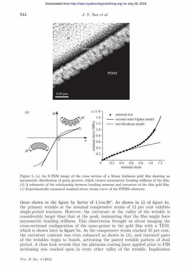
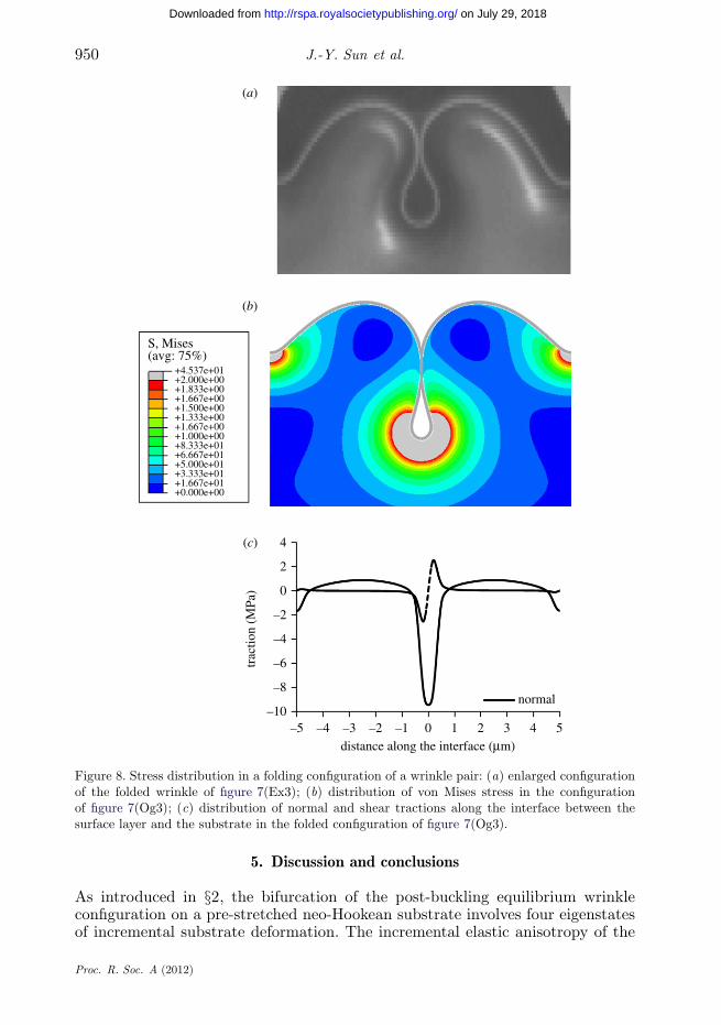
When a stiff layer is buckled on a compliant substrate, delamination ofinterface may occur even without a noticeable growth of wrinkle amplitude if theinterface bonding is weak (Shield et al. 1994). Therefore, we investigated the stressstate produced by a folded large-amplitude wrinkle. Figure 8 shows the simulatedwrinkling profile compared with experiment (figure 8a) and the von Mises stressdistribution (figure 8b) in (Og3) of figure 7. The von Mises stress distribution waslimited to 4.54 MPa. Figure 8c shows that the compressive interface traction atthe bottom of the closed valley was very large down to −9.46 MPa, while thetension was limited to 0.87 MPa. The maximum shear traction was 2.53 MPa.The results imply that the interface is well protected from tensile delaminationin large amplitude wrinkles on a soft substrate such as PDMS.
Proc. R. Soc. A (2012)
on July 29, 2018http://rspa.royalsocietypublishing.org/Downloaded from
950 J.-Y. Sun et al.
(a)
(c) 4
2
–2
trac
tion
(MPa
)
–5 –4 –3 –2 –1 0distance along the interface (mm)
1 2 3 4 5
normal
–4
–6
–8
–10
0
(b)
S, Mises(avg: 75%)
+4.537e+01+2.000e+00
+1.000e+00
+1.833e+00+1.667e+00+1.500e+00+1.333e+00
+8.333e+01
+3.333e+01
+1.667e+00
+1.667e+01+0.000e+00
+6.667e+01+5.000e+01
Figure 8. Stress distribution in a folding configuration of a wrinkle pair: (a) enlarged configurationof the folded wrinkle of figure 7(Ex3); (b) distribution of von Mises stress in the configurationof figure 7(Og3); (c) distribution of normal and shear tractions along the interface between thesurface layer and the substrate in the folded configuration of figure 7(Og3).
5. Discussion and conclusions
As introduced in §2, the bifurcation of the post-buckling equilibrium wrinkleconfiguration on a pre-stretched neo-Hookean substrate involves four eigenstatesof incremental substrate deformation. The incremental elastic anisotropy of the
Proc. R. Soc. A (2012)
on July 29, 2018http://rspa.royalsocietypublishing.org/Downloaded from
Folding wrinkles 951
pre-stretched substrate determines the −X2-direction decay rate of the eigenstate.The amplitude sharing between the eigenstates is decided by the interfaceboundary conditions compatible with the deformation of the surface layer. Theinterface compatibility condition provides the bifurcation eigenvalue problem forthe wave number of the sinusoidal buckling. Similar to the solution procedureof the first bifurcation point provided by the first-order perturbation analysisin §2, high-order asymptotic analysis is believed to be possible to follow the post-bifurcation equilibrium paths for the growth of wrinkles. The asymptotic analysisis also considered to be possibly extended beyond the neo-Hookean model of thesubstrate and the symmetric-bending-stiffness model of the surface layer.
When we followed the post-buckling equilibrium configurations of the primarywrinkles in 20–80 nm thin gold films attached on a pre-stretched PDMS substrate,we experimentally observed the second and the third bifurcation points withinthe stretch ratio of 1 ≤ l ≤ lps = 2.1. The second and the third bifurcationsgenerated periodic clustering or bunching of wrinkles. FIB sectioning revealedthat the clustering led to folding of the wrinkles when the surface layer washighly compressed. While multi-scale clustering of small-amplitude wrinkles maybe possible on a substrate with graded material properties, folding of the wrinklesrequires multiple symmetry-breaking nonlinear material characteristics of boththe substrate and the surface layer. Our computational tracing of the equilibriumwrinkle configurations revealed that the neo-Hookean substrate could not fold thewrinkles regardless of the elastic surface-layer nonlinearity. In contrast, the Ogdensubstrate could fold the wrinkles as observed in the experiments, if the surface-layer stiffness was asymmetric in bending. However, when the bending stiffness ofthe surface layer was symmetric, the Ogden model could not produce the foldedwrinkles either.
The folding of the wrinkles is believed to be retarded or promoted by inelasticbehaviour of the film and the substrate. Viscoelastic behaviour of the substrate(Huang 2005) may provide time-dependent folding behaviour of the wrinkles.Plastic bending and unbending processes of the surface layer (Kim & Kim1988) can also generate different wrinkle patterns than predicted by the elasticanalysis. Our in situ AFM measurement of the wrinkle wavelengths stronglysuggests that the phase of the wrinkle curvature was locked in the undeformedconfiguration of the film. The wavelength of the primary wrinkle conformallyfollowed the stretch of the substrate when the gold film was compressed to befolded. In addition, the film flatness was not recovered when it was fully relaxed;instead, plastically deformed wrinkle grooves remained. Once the wrinkle phase islocked in the undeformed configuration by the surface-layer plasticity, incrementalconfiguration forces (Kim et al. 2010) caused by the external compression loadingmay unlock the phase by unbending the plastically deformed surface layer.Further studies on inelastic effects of the materials on wrinkle folding are inprogress. The multiple folds of thin films with nanometre-scale thickness areexpected to have extensive applications such as nano-fluidics in the parallel nano-channels of the folding wrinkles, self-cleaning adhesion control with concealingand re-exposing surfaces, and creation of nanometre-scale solid reaction surfacesfor catalysts and battery electrodes.
S.X. and K.S.K. were supported by the U.S. National Science Foundation (DMR-0520651) throughMRSEC at Brown University, and by Korea Institute of Science and Technology (KIST); M.W.M.by KIST and in part by the Ministry of Knowledge Economy of Korea through the Fundamental
Proc. R. Soc. A (2012)
on July 29, 2018http://rspa.royalsocietypublishing.org/Downloaded from
952 J.-Y. Sun et al.
R&D Program for Core Technology of Materials; J.Y.S. and K.H.O. were supported by BasicScience Research Program through the National Research Foundation of Korea (NRF) funded bythe Ministry of Education, Science and Technology (R11-2005-065). We also thank M. Diab forvaluable discussions and the late H. M. Rho for his support for the hybrid computational analysis.
References
Allen, H. G. 1969 An introduction to sandwich construction. New York, NY: Pergamon.Biot, M. A. 1957 Folding instability of a layered viscoelastic medium under compression. Proc. R.
Soc. Lond. A 242, 444–454. (doi:10.1098/rspa.1957.0187)Biot, M. A. 1965 Mechanics of incremental deformation. New York, NY: Wiley.Bowden, N., Brittain, S., Evans, A. G., Hutchinson, J. W. & Whitesides, G. M. 1998 Spontaneous
formation of ordered structures in thin films of metals supported on an elastomeric polymer.Nature 393, 146–149. (doi:10.1038/30193)
Cerda, E. & Mahadevan, L. 2003 Geometry and physics of wrinkling. Phys. Rev. Lett. 90, 074302.(doi:10.1103/PhysRevLett.90.074302)
Chan, E. P., Smith, E. J., Hayward, R. C. & Crosby, A. J. 2008 Surface wrinkles for smart adhesion.Adv. Mater. 20, 711–716. (doi:10.1002/adma.200701530)
Chen, X. & Hutchinson, J. W. 2004 Herringbone buckling patterns of compressed thin films oncompliant substrates. J. Appl. Mech. 71, 597–603. (doi:10.1115/1.1756141)
Efimenko, K. et al. 2005 Nested self-similar wrinkling patterns in skins. Nat. Mater. 4, 293–297.(doi:10.1038/nmat1342)
Genzer, J. & Groenewold, J. 2006 Soft matter with hard skin: from skin wrinkles to templatingand material characterization. Soft Matter 2, 310–323. (doi:10.1039/b516741h)
Gough, G. S., Elam, C. F. & de Bruyne, N. A. 1940 The stabilization of a thin sheet by a continuoussupporting medium. J. R. Aero. Soc. 44, 12–43.
Hoff, N. J. & Mautner, S. E. 1945 The buckling of sandwich-type panels. J. Aero. Sci. 12, 285–297.Huang, R. 2005 Kinetic wrinkling of an elastic film on a viscoelastic substrate. J. Mech. Phys.
Solids 53, 63–89. (doi:10.1016/j.jmps.2004.06.007)Huang, Z. Y., Hong, W. & Suo, Z. 2005 Nonlinear analyses of wrinkles in a film bonded to a
compliant substrate. J. Mech. Phys. Solids 53, 2101–2118. (doi:10.1016/j.jmps.2005.03.007)Huck, W. T. S. 2005 Hierarchical wrinkling. Nat. Mater. 4, 271–272. (doi:10.1038/nmat1356)Kim, K.-S. & Kim, J. 1988 Elasto-plastic analysis of the peel test for thin film adhesion. J. Eng.
Mater. Tech. 110, 266–273. (doi:10.1115/1.3226047)Kim, S. O., Earmme, Y. Y. & Kim, K.-S. 2010 Useful conservation sums in molecular dynamics
and atomistics. Math. Mech. Solids, 15, 885–895. (doi:10.1177/1081286509357338)Lee, D., Triantafyllidis, N., Barber, J. R. & Thouless, M. D. 2008 Surface instability of an elastic
half space with material properties varying with depth. J. Mech. Phys. Solids 56, 858–868.(doi:10.1016/j.jmps.2007.06.010)
Moon, M.-W. et al. 2007 Wrinkled hard skins on polymers created by focused ion beam. Proc. NatlAcad. Sci. USA 104, 1130–1133. (doi:10.1073/pnas.0610654104)
Ogden, R. W. 1972 Large deformation isotropic elasticity—on the correlation of theory andexperiment for incompressible rubberlike solids. Proc. R. Soc. Lond. A 326, 565–584. (doi:10.1098/rspa.1972.0026)
Ogden, R. W. 1998 Non-linear elastic deformations: New York, NY: Dover.Rahmawan, Y., Moon, M.-W., Kim, K.-S., Lee, K. R. & Suh, K. Y. 2010 Wrinkled, dual-scale
structures of diamond-like carbon (DLC) for superhydrophobicity. Langmuir 26, 484–491.(doi:10.1021/la902129k)
Rivlin, R. S. 1948 Large elastic deformations of isotropic materials. II. Some uniqueness theoremsfor pure, homogeneous deformation. Phil. Trans. R. Soc. Lond. A 240, 491–508. (doi:10.1098/rsta.1948.0003)
Röll, K. 1976 Analysis of stress and strain distribution in thin films and substrates. J. Appl. Phys.47, 3224–3229. (doi:10.1063/1.323119)
Proc. R. Soc. A (2012)
on July 29, 2018http://rspa.royalsocietypublishing.org/Downloaded from

Folding wrinkles 953
Shield, T. W., Kim, K.-S. & Shield, R. T. 1994 The buckling of an elastic layer bonded to an elasticsubstrate in plane strain. J. Appl. Mech. 61, 231–235. (doi:10.1115/1.2901434)
Song, J. et al. 2008 Buckling of a stiff thin film on a compliant substrate in large deformation.Int. J. Solids Struct. 45, 3107–3121. (doi:10.1016/j.ijsolstr.2008.01.023)
Stafford, C. M. et al. 2004 A buckling-based metrology for measuring the elastic moduli of polymericthin films. Nat. Mater. 3, 545–550. (doi:10.1038/nmat1175)
Steigmann, D. J. & Ogden, R. W. 1997 Plane deformations of elastic solids with intrinsic boundaryelasticity. Proc. R. Soc. Lond. A 453, 853–877. (doi:10.1098/rspa.1997.0047)
Timoshenko, S. P. & Gere, J. M. 1961 Theory of elastic stability. New York, NY: McGraw-Hill.Yoo, S. H., Cohen, C. & Hui, C.-Y. 2006 Mechanical and swelling properties of PDMS inter-
penetrating polymer networks. Polymer 47, 6226–6235. (doi:10.1016/j.polymer.2006.06.035)
Proc. R. Soc. A (2012)
on July 29, 2018http://rspa.royalsocietypublishing.org/Downloaded from

rspa.royalsocietypublishing.org
CorrectionCite this article: Sun J-Y, Xia S, Moon M-W,Oh KH, Kim K-S. 2013 Folding wrinkles of a thinfilm stiff layer on a soft substrate. Proc R Soc A469: 20120742.http://dx.doi.org/10.1098/rspa.2012.0742
Folding wrinkles of a thin filmstiff layer on a soft substrateJeong-Yun Sun, Shuman Xia, Myoung-Woon Moon,
Kyu Hwan Oh and Kyung-Suk Kim
Proc. R. Soc. A 468, 932–953 (8 April 2012; Publishedonline November 23 2011) (doi:10.1098/rspa.2011.0567)
There is a typo in equation (2.4b) of Jeong-Yun Sun,Shuman Xia, Myoung-Woon Moon, Kyu Hwan Oh andKyung-Suk Kim, ‘Folding wrinkles of a thin film stifflayer on a soft substrate’.
It is currently published as UN−H = Q(λ21 + λ2
2 + λ23 − 3);
but it should read as
UN−H = Q2 (λ2
1 + λ22 + λ2
3 − 3) (the factor 1/2 was missing).
c© 2013 The Author(s) Published by the Royal Society. All rights reserved.