FM Series Flail Mowers - Chapman Machinery...
29
FM Series Flail Mowers All Models Original Instructions Chapman Machinery Ltd, Hele Barton, Week St. Mary, Holsworthy, Devon EX22 6XR Tel: 01288 308149 Email: [email protected]
Transcript of FM Series Flail Mowers - Chapman Machinery...

FM Series Flail MowersAll Models
Original InstructionsChapman Machinery Ltd, Hele Barton, Week St. Mary, Holsworthy, Devon EX22 6XR
Tel: 01288 308149Email: [email protected]
Page 2
Contents4 Introduction5 HSE Information9 Important Safety Information -Definitions - Safety Information - Transportation Safety - Operation safety11 Description -Identification -Specification12 Technical Information -ComponentIdentification - Optional Equipment - Noise Levels - Location of Machine Safety Features13 Implement Decals15 Attachment - Before Attaching the Machine - Attaching the Machine16 Operation - Operating Limits - Daily Checks - Offsetting - Starting Work - Forward Speed - Storage19 Drive Belts & Power Transmission - Belts - Centrifugal Clutch20 Belt Replacement - Old Type Tensioner (Models pre- 09/14) - New Type Tensioner (09/14 - Present)23 Maintenance - Maintenance Schedule24 Maintenance Instructions - Grease Points - Flail Condition & Replacement

Page 3
- Tyre Pressures26 Troubleshooting26 Machine Disposal27 Warranty - The Chapman Warranty - Warranty Conditions29 CE Declaration of Conformity

Page 4
Introduction
By purchasing a Chapman Machinery FM Series Flail Mower you have purchased a product designed to giveafirstclassfinishandalsohavealonglifespan,ifusedandmaintainedcorrectlyasdetailedinthismanual.
Avarietyofoptionsareavailablefromthefactory,andmanyofthesearealsosuitableforretro-fitmentifyour requirements change, or you purchase this machine used, and wish to use a different set-up. We are more than happy to offer advice & support throughout the lifetime of the machine.
This manual also contains important Health & Safety Executive information and guidelines.
NOTICE:
THIS MANUAL MUST BE HANDED TO THE OPERATOR BEFORE USE. THE OPERATOR MUST UNDERSTAND FULLY THE CONTENT OF THIS HANDBOOK BEFORE USING THE MACHINE FOR THE FIRST TIME. OF THE IMPLEMENT IS RESOLD, THIS MANUAL MUST ACCOMPANY THE MACHINE.
Note:
The information contained in this manual is correct at the time of going to press. However, in the course of development,changesinspecificationareinevitable.Shouldyoufindtheinformationgivendiffersfromyou machine, please contact your equipment supplier or Chapman Machinery Ltd direct for any after sales advice.
Chapman Machinery LtdHele Barton
Week St.MaryHolsworthy
DevonEX22 6XR
Tel:01288 308149Email: [email protected]
Page 5
HSE Information
Introduction
This information sheet gives advice on the safe use of
ATVs. It covers the two main types used in off-road
working in agriculture and forestry, which are:
� sit-astride ATVs: any motorised vehicle designed
to travel on four low-pressure tyres on unpaved
surfaces, with a seat designed to be straddled by
the operator and handlebars for steering control.
They are intended to be used by a single operator
with no passenger. However, this type also
includes ATVs intended for use by a single
operator, but with a special seat for a passenger
behind the operator. These vehicles are generally
called ATVs in agriculture, quad bikes in leisure
use and all-terrain cycles (ATCs) in forestry;
� sit-in machines: side-by-side mini-utility vehicles,
usually with a steering wheel, where the driver sits
in a conventional seat and there is generally
seating for one or more passengers. These are
often called ATVs in both agriculture and forestry.
The ATVs covered by this sheet are those designed for
off-road use only. However, agricultural, horticultural
and forestry users can register an ATV as a ʻLight
agricultural vehicleʼ for limited on-road use in
connection with their business (see ʻRoad useʼ).
Accidents
Both types of machine are designed to cope with a
wide variety of terrain types, including steep slopes, but
if used outside their safe operating parameters they
can very rapidly become unstable. This is why most
ATV accidents involve overturning.
On average, two people die each year in ATV
accidents. Non-fatal accidents are estimated to amount
to over 1000 serious injuries per year. The underlying
causes of accidents were usually one or more of the
following:
� lack of structured training and/or experience;
� incorrect/lack of protective clothing;
� excessive speed;
� carrying a passenger or an unbalanced load;
� tipping on a bank, ditch, rut or bump;
� a steep slope combined with other factors, eg
ground or load conditions;
� towing excessive loads with unbraked equipment.
Route planning and stability
Most accidents with these machines have occurred
where they have either been driven on new routes over
steep ground for the first time, or have been carrying or
dragging destabilising loads. When travelling over
rough terrain, get to know your own ground and stick to
planned routes where possible. Walk new routes if
necessary to check for hidden obstructions. Allow for
changes in ground conditions and for the destabilising
effect of loads or attachments.
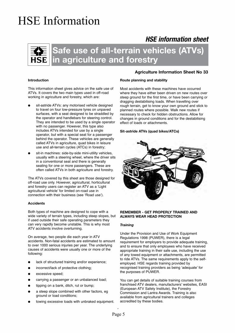
Sit-astride ATVs (quad bikes/ATCs)
REMEMBER - GET PROPERLY TRAINED AND
ALWAYS WEAR HEAD PROTECTION
Training
Under the Provision and Use of Work Equipment
Regulations 1998 (PUWER), there is a legal
requirement for employers to provide adequate training,
and to ensure that only employees who have received
appropriate training in their safe use, including the use
of any towed equipment or attachments, are permitted
to ride ATVs. The same requirements apply to the self-
employed. HSE regards training provided by
recognised training providers as being ʻadequateʼ for
the purposes of PUWER.
You can get details of suitable training courses from
franchised ATV dealers, manufacturersʼ websites, EASI
(European ATV Safety Institute), the Forestry
Commission and Lantra Awards. Training is also
available from agricultural trainers and colleges
accredited by these bodies.
1
Safe use of all-terrain vehicles (ATVs)in agriculture and forestry
HSE information sheet
Agriculture Information Sheet No 33
Page 6
Protective clothing
More than half of all ATV riders have been thrown off at
some time. As these machines are not fitted with either
a cab or roll bar, your only protection is what you wear.
� Head protection is vital. The majority of ATV
fatalities in the UK in the last ten years have been
caused by head injuries. Nobody who died from
head injuries was wearing a helmet. Helmets
would certainly have prevented most, if not all, the
deaths. You should always wear a helmet when
riding an ATV. Helmet types suitable for ATV
operations, depending on the circumstances, are
motorcycle helmets to BS 6658:1985 or UN ECE
regulation 22.05, equestrian helmets to BS EN
1384:1997, including specialist ATV helmets, cycle
helmets to BS EN 1078:1997 and mountaineering
helmets to BS EN 12492:2000. All helmets should
have a chinstrap and be capable of being used
with suitable eye protection. The type of helmet
chosen should be based on an assessment of the
circumstances in which the ATV will be used, eg
the types of surface travelled over and anticipated
speeds. The harder the surface and higher the
speed the greater the degree of protection
needed. NB: Forestry helmets and industrial
hard hats are not acceptable for any ATV
operations.
� Wear clothing that is strong and covers your arms
and legs. Gloves are useful for protection and to
keep hands warm in cold weather for good control
of the ATV. Wear sturdy, ankle-covering footwear,
eg boots or wellingtons that are strong, supportive
and have good wet grip.
� Protect your eyes from insects and branches with
either a visor or goggles.
Passengers
Never carry a passenger on a sit-astride ATV unless
it has been designed for, and is suitable for, that
purpose. The long seat is for operators to shift their
body weight backwards and forwards for different slope
conditions, not for carrying passengers. Passengers on
specially adapted ATVs must wear a safety helmet. Do
not carry a passenger in a trailer behind an ATV as any
movement can make the machine unstable, particularly
with independent rear suspension and trailers with
axles wider than the ATV.
Safety checks and maintenance
Off-road use is especially harsh on equipment so it is
essential to carry out safety checks and maintenance in
accordance with the manufacturerʼs recommendations.
In particular, pre-ride safety checks should always
include:
� tyre pressures. These are low, eg around 2-7 psi,
so even a 1 psi (0.07 kg/cm2) difference in
pressure can cause vehicle control problems.
Use a gauge that is designed for measuring and
displaying low pressures – usually supplied with
the ATV;
� brakes and throttle. Check that the brakes give a
safe straight stop and that the throttle operates
smoothly in all steering positions. Brakes can
have a relatively short life in farming or forestry
environments and need frequent cleaning, regular
adjustment and proper maintenance.
Safe driving methods
ATVs are rider-active machines, so rider positioning is
vital to operate them correctly. The position of the rider
on the machine needs to be changed depending on the
terrain and motion. Riders must have the ability to
move and balance the momentum of the ATV with their
own body weight. Plan routes (and review the plan if
the route is used regularly) to assess risks.
The following advice is no substitute for formal
training.
� Most ATVs have no differential and so do not
handle in the same way as other machines. This
means that when you turn, the ATV tries to keep
going in a straight line.
� When cornering on an ATV with no differential or
with the differential lock engaged, where your
body weight needs to be positioned depends on
how sharp the corner is and on how fast you are
going. Correct body position allows you to transfer
weight to the outside of the turn through the
footrests while maintaining balance with the torso.
This lets the inside wheels skid slightly allowing
the ATV to make the turn properly.
� You must understand how the transmission
system of your machine will affect engine braking
for both riding, and recovery of stalled ATVs, on
slopes.
� When riding across a slope, keep your weight on
the uphill side of the ATV.
� When going downhill, slide your weight
backwards, select a low gear and use engine
braking, reducing the need to use the brakes.
� When going uphill, it is important to review the
route before starting the climb. Move your weight
forwards and maintain a steady speed. It is
important to shift your body weight forwards as
much as possible. If necessary stand up and lean
forward, keeping both feet on the footrests at all
times and always maintain momentum.
� Avoid sudden increases in speed, as this is a
common cause of rearward overturning accidents,
even from a standing start on flat ground where
there is good grip.
2
Page 7
� Never put your foot onto the ground to
stabilise an ATV when riding, but shift your
weight across the ATV away from the imbalance.
� Always read the owner’s manual.
Trailed equipment and loads
Ensure all riders know the manufacturerʼs
recommended towing capacity and drawbar loading
limit. Always operate within these requirements.
Remember that your ability to control the ATV by your
body movements will be considerably reduced when
carrying a load or towing a trailer.
� When selecting trailed equipment look for:
- over-run brakes;
- a swivel hitch drawbar;
- bead lock rims on wheels;
- a low centre of gravity and a wide wheel
track;
- a long drawbar; and
- attachment points for securing a load.
� Check the weight ratio between your ATV and its
trailed load. This needs to be assessed for each
operation. As a general guide, on level ground,
braked trailed equipment can be a maximum of
four times the unladen weight of the ATV. For
unbraked trailed equipment the maximum should
be twice the unladen weight. These loads should
be reduced when working on slopes, uneven
ground or poor surface conditions. Follow the
manufacturerʼs advice for your particular machine.
� Weight transfer is also important. Stability and
resistance to jack-knifing is improved if some load
is transferred onto the ATVʼs drawbar.
Approximately 10% of the gross weight of the
loaded trailer is recommended, but this should not
exceed the manufacturerʼs drawbar loading limit.
Remember that weight transfer can change
dramatically when you start going up or down hill.
� When selecting mounted equipment, make sure it
is within the manufacturerʼs approved weight limit,
with a low centre of gravity, and controls which are
easy to operate but do not create a hazard. Where
equipment is added to one end of the machine,
add ballast at the other end to maintain stability.
� Loads carried on racks must be well secured, eg
with ratchet straps, and be evenly balanced
between the front and rear, except where they are
deliberately altered to aid stability when going up
or down a slope.
� Only tow a load from the hitch point. Loads towed
from other points such as the rear rack have
caused sudden rear overturning even on slight
slopes or with slight acceleration. Ropes or chains
should not be used to drag a load where they can
become caught on a wheel. This may lead to
entanglement with the brake cable, causing
unexpected braking.
Using sprayers
� Pesticides should be used in accordance with the
Code of Practice for using plant protectionproducts published by Defra. (Available fromDefra Publications, ADMAIL 6000, London SW1A
2XX Tel: 08459 556000.)
� Sprayers should meet the requirements of BS EN
907 and be fitted with an induction hopper unless
the filling point is less than 1.5 m from the ground
and within 0.3 m from the edge of the sprayer. A
separate clean water tank for washing must be
provided containing at least 15 litres of clean
water and a tap that allows the water to run
without being continuously pressed.
� When buying a sprayer look for a low centre of
gravity and internal baffles to reduce liquid surge
to improve stability when turning on slopes.
� ATVs should only be used with rear-mounted
spray booms or other equipment that reduces the
risk of pesticide exposure to the operator.
� Do not hold a spraying lance while riding your
ATV, as two hands are needed for safe control.
Accessories
Beware of the potential dangers of accessories which
are not approved by manufacturers, eg home-made
gun racks and boxes. Either use accessories
supplied/approved by manufacturers or seek their
advice as to the suitability of those sourced elsewhere.
Any weight added above the centre of gravity will
decrease the ATVʼs stability.
Children
� Never carry a child as a passenger. It is illegal and
will reduce your ability to control the ATV.
� Children under 13 are prohibited from using an
ATV at work. Over 13 they should only ride ATVs
of an appropriate size and power, after formal
training on a low-power ATV.
� Check and adhere to the manufacturer’s
minimum age recommendations for your ATV.
The ratio of a childʼs weight to that of the ATV is
significant, as weight transfer is the key to safe
handling.
� Always refer to the ownerʼs manual and warning
labels on the machine.
Roll bars, lap straps and weather cabs
� Roll bars are not recommended for sit-astride
ATVs. Research has shown that they are more
likely to increase injuries by obstructing the rider,
either when thrown off or when jumping off during
an overturn. This causes the rider to fall to the
ground alongside the ATV and increases the
likelihood of injury. PUWER does not require roll
bars where they would increase the overall risk.
3
Page 8
� Lap straps should not be fitted. They prevent
active riding and would be potentially lethal
without a full cab or roll cage.
� Weather cabs restrict a riderʼs ability to jump clear
in an overturn. The rider is likely to be crushed
within the cab unless it is strong enough to
withstand the forces involved. Carefully assess the
risks for your particular conditions of use before
fitting any such structure and consult the
manufacturer for information.
Road use
For road use, ATVs and trailers have to comply with the
Road Vehicles Construction and Use Regulations 1986
(as amended) and the Road Vehicles Lighting
Regulations 1989 (both enforced by the police) and be
licensed in the appropriate class. They do not require
an MOT and the maximum permitted speed is 20 mph.
The minimum age for drivers is 17 and they need a
Category B licence.
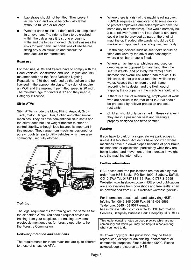
Sit-in ATVs
Sit-in ATVs include the Mule, Rhino, Argocat, Scot-
Track, Gator, Ranger, Hiler, Goblin and other similar
machines. They all have conventional sit-in seats and
the driver does not use weight transfer to steer or
control stability, although load balance is important in
this respect. They range from machines designed for
purely rough terrain to utility vehicles, which are also
commonly used fully off-road.
Training
The legal requirements for training are the same as for
the sit-astride ATVs. You should request advice on
training from your suppliers, the training providers
previously mentioned or, for forestry operations, from
the Forestry Commission.
Rollover protection and seat belts
The requirements for these machines are quite different
to those of sit-astride ATVs.
� Where there is a risk of the machine rolling over,
PUWER requires an employer to fit some device
to protect employees (the self-employed have the
same duty to themselves). This would normally be
a cab, rollover frame or roll bar. Such a structure
could either be provided as part of the original
machine or, if added afterwards, should be CE
marked and approved by a recognised test body.
� Restraining devices such as seat belts should be
fitted and worn by the driver and passengers
where a roll bar or cab is fitted.
� Where a machine is amphibious and used on
deep water as opposed to marshland, then the
seat restraints (and possibly roll frame) could
increase the overall risk rather than reduce it. In
this case, do not use seat restraints while on the
water. Assess the risk from the roll frame
according to its design and the likelihood of
trapping the occupants if the machine should sink.
� If there is a risk of overturning, employees at work
who are carried in the rear of sit-in ATVs should
be protected by rollover protection and seat
restraints.
� Children should only be carried in these vehicles if
they are in a passenger seat and wearing a
properly designed and fitted seatbelt.
Parking
If you have to park on a slope, always park across it
unless it is too steep. Accidents have occurred where
machines have run down slopes because of poor brake
maintenance or application, particularly while they are
being loaded, and movement or the increase in weight
sets the machine into motion.
Further information
HSE priced and free publications are available by mail
order from HSE Books, PO Box 1999, Sudbury, Suffolk
CO10 2WA Tel: 01787 881165 Fax: 01787 313995
Website: www.hsebooks.co.uk (HSE priced publications
are also available from bookshops and free leaflets can
be downloaded from HSEʼs website: www.hse.gov.uk.)
For information about health and safety ring HSEʼs
Infoline Tel: 0845 345 0055 Fax: 0845 408 9566
Textphone: 0845 408 9577 e-mail:
[email protected] or write to HSE Information
Services, Caerphilly Business Park, Caerphilly CF83 3GG.
This leaflet contains notes on good practice which are not
compulsory but which you may find helpful in considering
what you need to do.
© Crown copyright This publication may be freely
reproduced, except for advertising, endorsement or
commercial purposes. First published 05/99. Please
acknowledge the source as HSE.
Printed and published by the Health and Safety Executive AIS33 Reprinted 06/09 C150
Page 9
Important Safety InformationAlwaysreadthismanualbeforefittingoroperatingthemachine–wheneveranydoubtexistscontactyourdealer or the Chapman Machinery Service Department for advice and assistance.
Use only Chapman Genuine Service Parts on Chapman Machinery and Machines
DEFINITIONSThefollowingdefinitionsapplythroughoutthismanual:
WARNINGAnoperatingprocedure,techniqueetc.,which–canresultinpersonalinjuryorlossoflifeifnotobservedcarefully.
CAUTIONAnoperatingprocedure,techniqueetc.,which–canresultindamagetoeithermachineorequipmentifnotobserved carefully.
NOTEAnoperatingprocedure,techniqueetc.,which–isconsideredessentialtoemphasis.
Safety Information- Do not operate this equipment unless you have studied this manual in full
- Only use this machine for its intended purpose - improper use is both highly dangerous and potentially damaging to the equipment
-Bothoperators&maintenacefittersshouldbefamiliarwiththemachineandfullyawareofdangerssur-rounding inproper use or incorrect repairs
- Before starting, carry out a visual check on both machine & towing vehicle as regards functionality, road safety & accident prevention rules
-Evenwhenusingthemachinecorrectly,foreignobjectssuchasstonesmaybethrownaconsiderabledistance. It is imperative that nobody stand within the danger area. If working near roads, buildings children oranimalsprovisionmustbemadeforcontainmentofejectedmaterialandsufficientwarningsigns/noticesplaced around the working area
-Theconditionofflailsandofmachineguardsmustbecheckedbeforebeginningtheday’swork.Wornordamagedflailsmustbereplacedbeforeyouusethemachine.Flailsmustbereplacedinpairstoensurerotorbalance is maintained.
- During checks or repairs, ensure the machine cannot be started by other persons by mistake
- Never wear loose clothing which could get caught in rotating equipment
Page 10
- Never carry passengers on the towing vehicle
- Never approach the machine until the rotor has stopped rotating
- Do not stand near the machine when operating
- Damaged or missing safety decals must be replaced immediately
- Before leaving the machine unattended, remove the starting key (if applicable)
- ENSURE emergency stop switch is SECURELY attached to the towing vehicle and within reach of the operator at all times
Transportation Safety
- When transporting, especially over rough ground, reduce speed to prevent damage to machine.
- Ensure ignition keys are removed
- This machine is not road legal. DO NOT tow on public highways
- Never transport the machine with the rotor running, even for small distances.
Operating Safety
-Payspecialattentionwhenworkingwiththemachinenottotouchfixedobjectssuchasroad-drain,walls,shafts,kerbs,guardrails,tracksetc.Thiscouldcausebreakageoftheflails,whichcouldbethrownoutofthemachine at very high speed.
- If wires, ropes or chains should become entangled in the rotor stop immediately to prevent damage or dangerous situations; stop the rotor and the towing machine, take out the starting key or safety cut-out. Put working gloves on; clear the rotor with the aid of pliers or shears. Do not try to disentangle
- Do not use the machine when excessive vibration is experienced, as this may causebreakageandseriousdamage-findthecauseofthevibrationandeliminateitbeforeusingthemachineagain.
Page 11
DescriptionTheFMSeriesofflailmowersaredesignedasself-poweredunitstobetowedbehindasuitable,ATV,UTV,4X4, compact tractor or lawn tractor towing vehicles. Designed for vegetation management of paddocks, fieldsandparkland,theFMseriescanhandlematerialuptosmallsaplingsandbrush.
TheFM120hasa1.2mcut,andisavailablewithaHondaGX63021hpV-Twinelectricstartpetrolengine.The FM150 has a 1.5m cut and is available with the same Honda 21hp engine.
These machines should however only be used to perform tasks for which they were designed - use of the machine for any other function may be both dangerous to persons, and potentially damaging to components. Use of the machine beyond the stated usage may invalidate any applicable warranty, as well as being poten-tial in breach of applicable safety regulations.
IdentificationEachmachineisfittedwithaserialplatewhichdetailsthefollowing:
1. Model No.2. Date of Manufacture (DOM)3. Serial No.4. Mass
When enquiring regarding spares or additional equipment, ensure you have this information to hand.
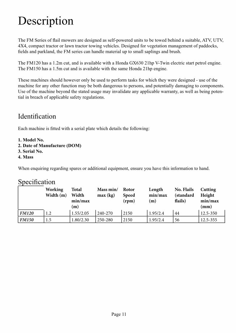
SpecificationWorking Width (m)
Total Width min/max (m)
Mass min/max (kg)
Rotor Speed (rpm)
Length min/max (m)
No. Flails (standard flails)
Cutting Height min/max (mm)
FM120 1.2 1.55/2.05 240-270 2150 1.95/2.4 44 12.5-350FM150 1.5 1.80/2.30 250-280 2150 1.95/2.4 56 12.5-355
Page 12
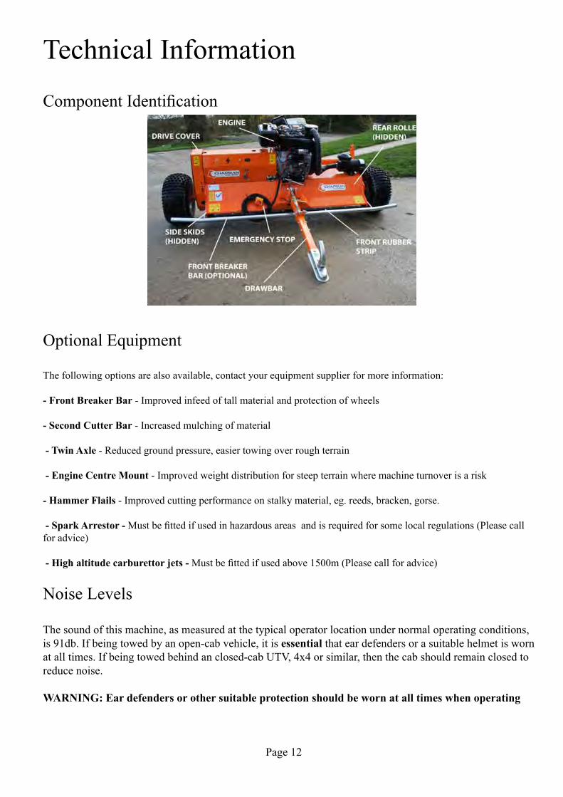
Technical Information
ComponentIdentification
Optional Equipment
The following options are also available, contact your equipment supplier for more information:
- Front Breaker Bar - Improved infeed of tall material and protection of wheels
- Second Cutter Bar - Increased mulching of material
- Twin Axle - Reduced ground pressure, easier towing over rough terrain
- Engine Centre Mount - Improved weight distribution for steep terrain where machine turnover is a risk
- Hammer Flails - Improved cutting performance on stalky material, eg. reeds, bracken, gorse.
- Spark Arrestor - Mustbefittedifusedinhazardousareasandisrequiredforsomelocalregulations(Pleasecallfor advice)
- High altitude carburettor jets - Mustbefittedifusedabove1500m(Pleasecallforadvice)
Noise Levels
The sound of this machine, as measured at the typical operator location under normal operating conditions, is 91db. If being towed by an open-cab vehicle, it is essential that ear defenders or a suitable helmet is worn atalltimes.Ifbeingtowedbehindanclosed-cabUTV,4x4orsimilar,thenthecabshouldremainclosedtoreduce noise.
WARNING: Ear defenders or other suitable protection should be worn at all times when operating
Page 13
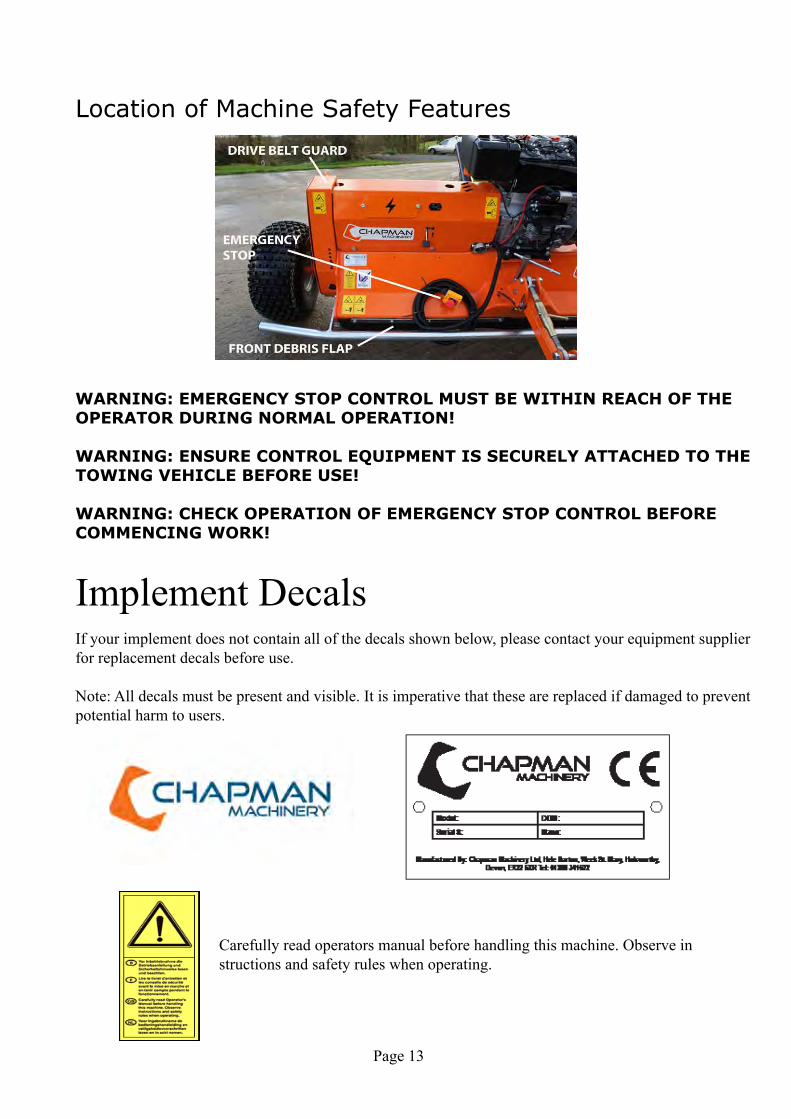
Location of Machine Safety Features
WARNING: EMERGENCY STOP CONTROL MUST BE WITHIN REACH OF THE OPERATOR DURING NORMAL OPERATION!
WARNING: ENSURE CONTROL EQUIPMENT IS SECURELY ATTACHED TO THE TOWING VEHICLE BEFORE USE!
WARNING: CHECK OPERATION OF EMERGENCY STOP CONTROL BEFORE COMMENCING WORK!
Implement DecalsIf your implement does not contain all of the decals shown below, please contact your equipment supplier for replacement decals before use.
Note: All decals must be present and visible. It is imperative that these are replaced if damaged to prevent potential harm to users.
Carefully read operators manual before handling this machine. Observe in structions and safety rules when operating.

Page 14
Caution-EntanglementHazard.Keephandsawayfromrotatingcomponents
Caution - Rotating blades. Maintain sensible working distance from machine and keep hands and feet clear of blades
Caution-riskofflyingobjects.Keepasafedistancefrommachineatalltimes
Page 15
AttachmentBefore Attaching the Machine
Before attachment, ALWAYS ensure the following:
-Allsafetyguards&decalsareingoodworkingorderandcorrectlyfitted-Allbladesarecorrectlyfitted,undamaged,andnotworntoexcess - Lubrication points have been lubricated as per scheduled maintenance period - The engine oil level is correct & has been maintained as per the handbook - Drive belt(s) are in good working order-Thetyresarefreeofdamageandinflatedtothecorrectpressure
Attaching the MachineNOTE: This machine is designed to attach to the towing vehicle through a 50mm diameter ball hitch or pin hitch.
1. Reverse the towing vehicle up to the machine.
2.Attachthemachineontothetowingvehicle’scouplingusingeithertheauto-lockcouplingorsuitablepinhitch. Ensure the hitch is securely attached to the towing vehicle
3. Attach the emergency stop contol box to the towing vehicle, in a secure location within easy reach by the operator.
WARNING: EMERGENCY STOP MUST BE WITHIN REACH OF THE OPERATOR DURING NORMAL OPERATION!
WARNING: ENSURE CONTROL EQUIPMENT IS SECURELY ATTACHED TO THE TOWING VEHICLE BEFORE USE!
WARNING: CHECK OPERATION OF EMERGENCY STOP CONTROL BEFORE COMMENC-ING WORK!
4.WiththeengineOFF,adjusttheworkingheighttoasuitablelevelbyturningtheheightadjusteratthefront left of the machine.
5. Level the machine to suit the drawbar & cutting height. This is achieved by twisting the link connector fittedtothedrawbar.Whenonlevelground,thetopfaceofthemowerdeck(wheretheengineismounted)should be approximately parallel to the ground.

Page 16
OperationNOTE: Ensurethattheoperatorissuitablyqualifiedtouseamachineofthisnatureandthattheyhavefullyread and understood this manual - they should be aware of all safety aspects relating to the safe use of the machine.
Priortostartingworktheareatobecutshouldbecheckedfordangerousobjectssuchaslargestones,wood,wire,glassetc.–hazardousobjectsshouldberemovedfromtheareapriortooperationwiththemachine.Thelocationofunmovableornaturalhazardssuchasdraincoversshouldbenoted,orifnecessary‘marked’,toindicatetotheoperatorthattheareashouldeitherbeavoidedoradditionalcautionadoptedwhilstworkingaroundthehazard.
Operating LimitsWARNING: DO NOT OPERATE BEYOND OPERATING LIMITS, DAMAGE TO MACHINERY OR INJURY TO OPERATOR MAY OCCUR.
Minimum / Maximum Ambient Temperature: -15°C / 40°C
Minimum / Maximum Altitude: 0 metres / 1500 metres *
Maximum Inlinination: 20° in any direction
*Adjustmenttocarburettorjetsizeabove1500mwillallowoperationabovethislevel,pleasecallforad-vice.
Daily ChecksBefore use each day, and with the engine switched off and keys removed, the following checks should be undertaken;
• Flails-Withtheengineswitchedoffandkeysremoved,theconditionoftheflailsshouldbechecked.Anydamagedormissingflailsshouldbereplacedimmediately.
• Engine - Fluid levels should be checked daily before use and topped-up as necessary. Ensure the air intake and screen grid are clear of debris. Ensure engine is in good order and maintained as per engine manufacturer schedule.
• Bearings - Ensure bearings are in good order and greased as per the maintenance schedule.• Belts - Ensure belts are in good order, free of debris, dirt and grease and do not have signs of damage eg.
cracking, frayed edges, uneven wear.• Fuel-Ensurefueliscleanandfreeofdirt/debris.Ifnecessarycheckconditionoffuelfilter.• Hitch - Check condition of swivel hitch, and ensure this is attached securely to towing vehicle.• Tyres-Ensuretyresarefreefromdamageandinflatedtothecorrectworkingpressurefortheconditions
at hand
Page 17
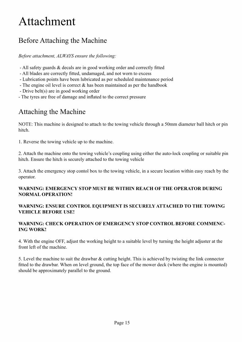
OffsettingIf required the drawbar on the FM Series can be offset to the left or right, or folded for storage.
The machine is offset by unscrewing the t-bar as shown below. The drawbar can then be moved to the de-siredlocation,andthet-barreplacedinasuitablehole.Thet-barmustbetightenedfirmlytopreventmove-ment of the drawbar, and should be checked periodically for tightness.
Semi-offset Folded for storage
WARNING: Changing the drawbar angle must be undertaken with the engine switched off & the ignition keys removed. Failure to do so could result in injury or damage to the machine.
Starting WorkAfter ensuring all daily checks have been undertaken (see above),and with the engine throttle on idle setting start the engine by turning the ignition key. Depending on the ambient temperature and engine temperature, choke may be required. Once the engine is running and choke off, engage drive by increasing the engine throttle to maximum.
WARNING: As the FM Series use a centrifugal clutch drive system, the engine must be run at maxi-mum speed AT ALL TIMES when cutting.
Forward SpeedThe forward working speed will depend greatly on the working conditions and nature of the material being cut. Optimal speed will be in the region of 3-8 km/h (2-5 mph).
StorageForextendedperiodsofstorageitisadvisablethatthemachinebefirstcleanedthoroughlyandfullylu-brcated. Any servicing and maintenance should be undertaken prior to storage, and any worn components replaced.
NOTE: Fuel should be treated with a suitable fuel stabiliser before extended storage! (SEE GUID-ANCE SHEET BELOW)

Page 18
30° m
axi
30° maxi
95 E-10 RON95 RON98 RON
5 liters
Problems caused by stale petrol can be avoided by following these simple tips.
Which kind of Petrol should you use?
hoW should Petrol be stored?
Maintenance of your Product.
• Regularunleaded98,95,95E5orE10canbeusedinhondaproducts(E5orE10contains5%or10%ethanol).
• Donotuseanypetrolcontainingmorethan10%ethanol.Thiswillcausecorrosiondamagetofuelsystemcomponents.
• hondadoesnotanticipateanynegativeeffectsfromtheuseofAlkylatetypepetrol.However,duetotheavailabilityofdifferentAlkylatefuels,norecommendationfortheirusecanbeprovidedatthistime.PleaserefertotheinstructionsanddatasheetprovidedbytheAlkylatemanufacturerformoreinformation.
• Ifyourhondaproduct isusedintermittently(egmorethan4weeksbetweeneachuse)usepetroltreatedwithfuelstabiliser,atthetimeofpurchase.
> honda fuel stabiliser has a shelf-life and its performance will deteriorate over time. Oncethebottleisopened,ithasamaximumlifeof2years.
>Fuelstabiliserwillnotreconstituteorreinvigoratestalepetrol.Itmustbeaddedwhenthe petrolisfresh.
• Petrolwillstarttodeteriorateifstoredformorethan1month.• Addhondafuelstabilisertofreshpetrolwhichislikelytobestoredformorethan1month.
• Onlyuseclean,sealed,approvedfuelcontainers,designedtospecificallycarryorstorepetrol.• Ifpetrolisstoredinasteelcontainer(egajerrycan)makesurethereisnocorrosionontheinsideof
thecontainer.
• Storepetrolinacoolplaceawayfromdirectsunlight.
• Ifyourhondaproductwillbeusedintermittently(egmorethan4weeksbetweeneachuse)usepetrolwhichhasbeentreatedwithfuelstabiliser,whenfresh.
• Turnthefueltapoff,whenthemachineisnotbeingused.• Beforeuse,checktheengineoilleveliscorrectandensuretheairfilterisclean.• before winter storage:
honda recoMMends
HONDAPARTNUMBER:08CXZFSC250
>Drainthepetrolfromthecarburettorandfueltank(refertoowner’smanualforcorrectprocedure).
OR
>Addfuelstabiliser,whichwillextendthestoragelifeofthepetrolremainingin thefuel tankandcarburettor.Fill thefuel tankto therecommendedmaximumlevel,usingtreatedpetrol.Runtheengineforatleast5minutestoallowtreatedpetroltoenterthecarburettor,priortostorage

Page 19
Drive Belts & Power TransmissionBeltsThe FM Series Flail Mowers utilise tow drive belts, driven through a centrifugal clutch, with a spring ten-sioned idler system to compensate for wear of the belts and pulleys.
Thedrivebeltsaredesignedasa‘weak-link’inthedrivetrain,suchthatthebeltswillfailbeforedamageiscausedtotheengineifaforeignobjectisencounteredorrotorentanglementoccurs.Drivebeltsareawear-ing part and as such are not covered by the machine warranty.
Dependingonmodelyear,yourFMSeriesMowerwillutiliseoneof3beltsizes;
Up to August 2012: BX40 / 17 x 1016August 2012 Onwards: BX41 / 16 X 1115Diesel Models Only: BX42
NOTE: Always replace belts as a pair. Replace with ‘matched set’ belts which have a consistent belt length.
Centrifugal ClutchAllmachinesintheFM120rangearefittedwithcentrifugalclutches,animportantsafetyfeaturetoactasoverload suppression & to allow easy starting & stopping of the machine. The centrifugal clutch is a sealed unit and will not require any maintenance.
NOTE: On some new machines the clutches can ‘stick’ on idle, before the cluctch linings bed-in & hence will operate before the normal clutch cut-in point. This is not a fault with the clutch or machine - after approximately 1-2 hours use the clutch will operate normally.
Page 20
Belt Replacement
Old Type Tensioner (Models pre- 09/14)
1. Adjusttheheightofthemowertothehighestsetting–thiswillgivethebestaccesstothedrivearea.Remove the drive cover by removing the top M10 bolt, and loosening the 2 lower M10 bolts.
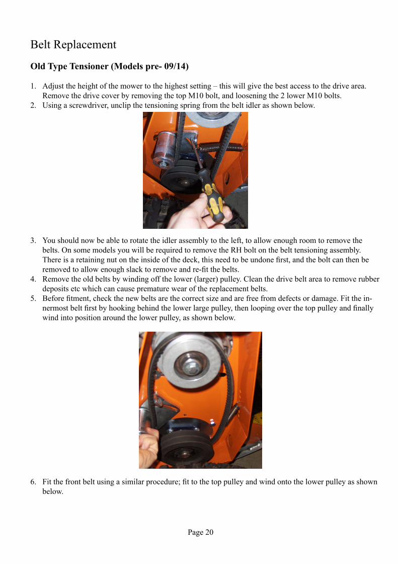
2. Using a screwdriver, unclip the tensioning spring from the belt idler as shown below.
3. You should now be able to rotate the idler assembly to the left, to allow enough room to remove the belts. On some models you will be required to remove the RH bolt on the belt tensioning assembly. Thereisaretainingnutontheinsideofthedeck,thisneedtobeundonefirst,andtheboltcanthenberemovedtoallowenoughslacktoremoveandre-fitthebelts.
4. Remove the old belts by winding off the lower (larger) pulley. Clean the drive belt area to remove rubber deposits etc which can cause premature wear of the replacement belts.
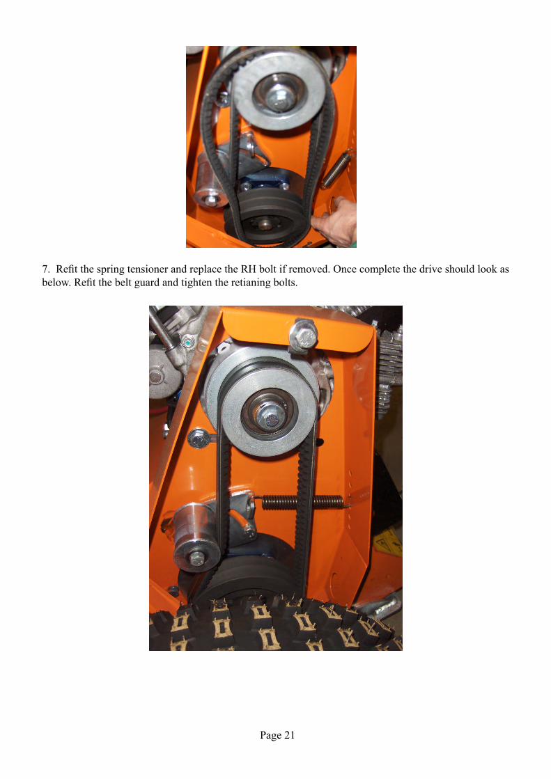
5. Beforefitment,checkthenewbeltsarethecorrectsizeandarefreefromdefectsordamage.Fitthein-nermostbeltfirstbyhookingbehindthelowerlargepulley,thenloopingoverthetoppulleyandfinallywind into position around the lower pulley, as shown below.
6. Fitthefrontbeltusingasimilarprocedure;fittothetoppulleyandwindontothelowerpulleyasshownbelow.
Page 21
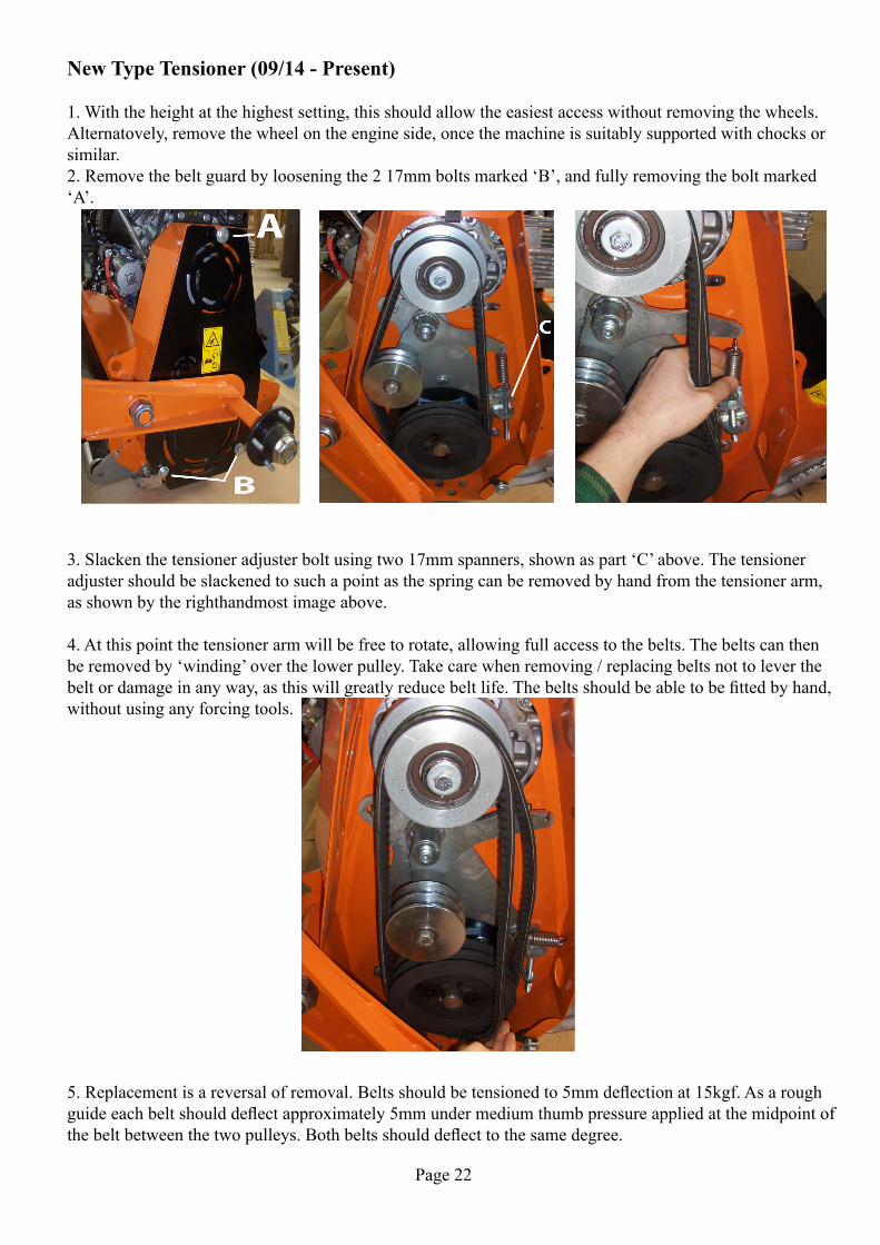
7.RefitthespringtensionerandreplacetheRHboltifremoved.Oncecompletethedriveshouldlookasbelow.Refitthebeltguardandtightentheretianingbolts.
Page 22
New Type Tensioner (09/14 - Present)
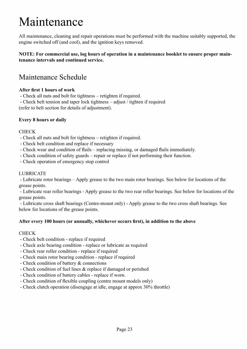
1. With the height at the highest setting, this should allow the easiest access without removing the wheels. Alternatovely, remove the wheel on the engine side, once the machine is suitably supported with chocks or similar.2.Removethebeltguardbylooseningthe217mmboltsmarked‘B’,andfullyremovingtheboltmarked‘A’.
3.Slackenthetensioneradjusterboltusingtwo17mmspanners,shownaspart‘C’above.Thetensioneradjustershouldbeslackenedtosuchapointasthespringcanberemovedbyhandfromthetensionerarm,as shown by the righthandmost image above.
4. At this point the tensioner arm will be free to rotate, allowing full access to the belts. The belts can then beremovedby‘winding’overthelowerpulley.Takecarewhenremoving/replacingbeltsnottoleverthebeltordamageinanyway,asthiswillgreatlyreducebeltlife.Thebeltsshouldbeabletobefittedbyhand,without using any forcing tools.
5.Replacementisareversalofremoval.Beltsshouldbetensionedto5mmdeflectionat15kgf.Asaroughguideeachbeltshoulddeflectapproximately5mmundermediumthumbpressureappliedatthemidpointofthebeltbetweenthetwopulleys.Bothbeltsshoulddeflecttothesamedegree.
Page 23
MaintenanceAll maintenance, cleaning and repair operations must be performed with the machine suitably supported, the engine switched off (and cool), and the ignition keys removed.
NOTE: For commercial use, log hours of operation in a maintenance booklet to ensure proper main-tenance intervals and continued service.
Maintenance Schedule Afterfirst1hoursofwork-Checkallnutsandboltfortightness–retightenifrequired.-Checkbelttensionandtaperlocktightness–adjust/tightenifrequired(refertobeltsectionfordetailsofadjustment).
Every 8 hours or daily
CHECK-Checkallnutsandboltfortightness–retightenifrequired. - Check belt condition and replace if necessary-Checkwearandconditionofflails–replacingmissing,ordamagedflailsimmediately.-Checkconditionofsafetyguards–repairorreplaceifnotperformingtheirfunction. - Check operation of emergency stop control
LUBRICATE-Lubricaterotorbearings–Applygreasetothetwomainrotorbearings.Seebelowforlocationsofthegrease points. - Lubricate rear roller bearings - Apply grease to the two rear roller bearings. See below for locations of the grease points. - Lubricate cross shaft bearings (Centre-mount only) - Apply grease to the two cross shaft bearings. See below for locations of the grease points.
Afterevery100hours(orannually,whicheveroccursfirst),inadditiontotheabove
CHECK - Check belt condition - replace if required - Check axle bearing condition - replace or lubricate as required - Check rear roller condition - replace if required - Check main rotor bearing condition - replace if required - Check condition of battery & connections - Check condition of fuel lines & replace if damaged or perished - Check condition of battery cables - replace if worn.-Checkconditionofflexiblecoupling(centremountmodelsonly) - Check clutch operation (disengage at idle, engage at approx 30% throttle)
Page 24
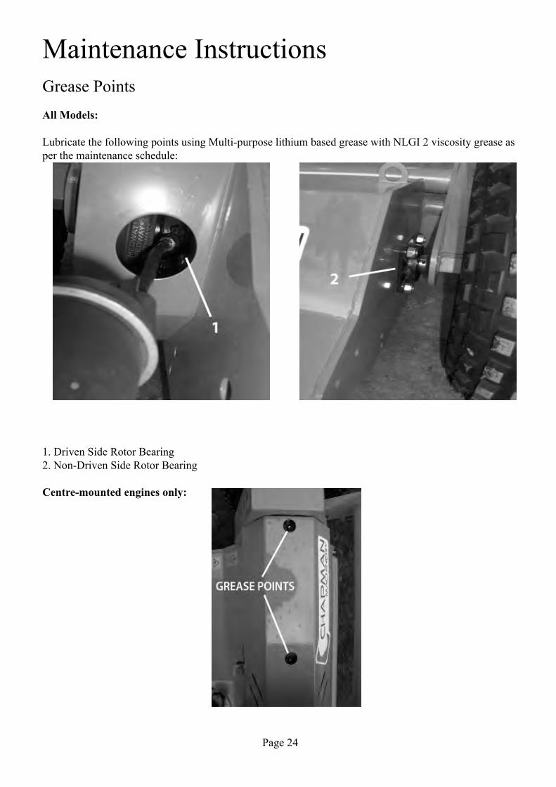
Maintenance InstructionsGrease PointsAll Models:
Lubricate the following points using Multi-purpose lithium based grease with NLGI 2 viscosity grease as per the maintenance schedule:
1. Driven Side Rotor Bearing2. Non-Driven Side Rotor Bearing
Centre-mounted engines only:

Page 25
Flail Condition & ReplacementOvertime,theflailsonyourmachinewillwear,andperformancewilldeteriorate.Itisimportantthattheflailsarekeptingoodconditiontoensurealongservicelifeofyourmachine.Flailsshouldbereplacedwheneither;3mmhaswornofftheendoftheflail;theflailhasbecomebluntordamaged;flailsaremissing.
Whenreplacingflailsthediameticallyoppositeflailshouldbereplacedatthesametimeinordertomaintainrotorbalance,Whenflailsarefittedinpairs,(eg.YGrassFlails),bothmustbereplacedatthesametime.Asflailsarefittedinaspiralpatterncaremustbetakentoreplacethecorrectdiametricallyoppositeflails.
Whenreplacingflailsvisuallyinspectthemountingboltsandbushes,ifapplicable.Theseareallwearingpartandnormallyshouldbereplacedatthesametimeastheflails.
Tyre PressuresFM120 - All variants inc. diesel
22x11x8 0.50-0.82 bar (7-12 psi)

Page 26
Troubleshooting
Problem Possible Causes RemediesIrregular Cut Worn, bent or broken flails Inspect & replace & damaged flails
RPM too low Always use maximum throttleMachine not level to the ground Check & adjust tyre pressures
Clogged material caused by exces-sive forward speed
Reduce forward speed
Excessive Machine Noise Unbalanced Rotor Check flails & replace any dam-aged flails. If vibration persists, see
“vibration” problem belowLoose bolts Check bolts & tighten as necessary
Damaged components Repair or replaceExcessive Engine Noise Worn muffler repair or replace
Engine problems Consult authorised dealer or Chapman Machinery service
centreExcessive Belt Noise Belts slipping Adjust belt tensioner
Belts worn Replace beltsVibration Worn, bent or broken flails Inspect and replace as necessary
Rotor out of balance Balance or replace rotorWorn rotor bearings Replace rotor bearings
Excessive movement of drawbar Worn drawbar pins Replace drawbar pinsLoose drawbar hand screws Tighten hand screws
Bearings tight or overheating Bearings dirty or ungreased Clean & grease bearingsBearings worn to excess Replace bearings
Belts Overheating Belts slipping on pulleys Tension beltsFlails contacting the ground Raise cutting height
Working speed too high Reduce forward speed
Machine DisposalDisposal of this machine and any of its component parts must be performed in a responsible and inoffensive mannerrespectingallcurrentlawsrelatingtothissubject.Materialsformingthismachinethatmustundergodifferentiated division and disposal are:–Steel–MineralOil–Rubber–Plastic

Page 27
Warranty
The Chapman WarrantyChapmanMachineryLtd(herein‘Chapman’or‘ChapmanMachinery’)warrantsthatthemachinereferredto in the Warranty Registration Form will be free from defects in materials and workmanship for a period of 12 months from the date of sale. This warranty does not affect your statutory rights, but merely adds to them. Should you have a problem within 12 months from the date of sale please contact your original dealer, orChapmanMachinery’sServiceDepartment.
Any part found to be defective during this period will be replaced or repaired, at our discretion, by the dealer or a authorised Service Engineer.
Warranty Conditions1. The Warranty Registration Form must be completed and returned to Chapman Machinery Ltd within 30 days of the date of sale
2. This warranty does not cover defects arising from fair wear and tear, wilful damage, negligence, misuse, abnormalworkingconditions,useincompetition,failuretofollowChapmanMachinery’sinstructions(oralorwritten,includingallinstructionsandrecommendationmadeintheOperator’sManual)oralterationorrepair of the machinery without prior approval.
3.ThemachinerymusthavebeenservicedinaccordancewiththeOperator’sManualandtheServiceLogmust have been kept up to date and made available to the dealer should service, repair or warranty work be undertaken.
4.Thiswarrantydoesnotcoverclaimsinrespectofwearingpartssuchasblades,flails,paintwork,tyres,belts, hydraulic hoses, bearings, bushes, linkage pins, top links, ball ends unless there is a manufacturing or material defect or the cost of normal servicing items such as oils and lubricants.
5. This warranty does not cover any expenses or losses incurred whilst the machinery is out of use for war-ranty repairs or parts replacement.
6. This warranty does not extend to parts, materials or equipment not manufactured by Chapman Machinery, forwhichtheBuyershallonlybeentitledtothebenefitofanysuchwarrantyorguaranteegivenbytheman-ufacturer to Chapman Machinery. Only genuine replacement parts will be allowable for warranty claims.
7. All parts replaced by Chapman Machinery under warranty become the property of Chapman Machinery and must be returned to Chapman Machinery if so requested. Such parts may only be disposed of after a warranty claim has been accepted and processed by Chapman Machinery.
8. Chapman Machinery is not liable under this warranty for any repairs carried out without Chapman Ma-chinery’swrittenconsentorwithoutChapmanMachinerybeingaffordedareasonableopportunitytoinspectthemachinerythesubjectofthewarrantyclaim.ChapmanMachinery’swrittenconsentmust,therefore,beobtained before any repairs are carried out or parts replaced. Use of non- Chapman Machinery parts auto-matically invalidates the Chapman Warranty. Failed components must not be dismantled except as

Page 28
specificallyauthorisedbyChapmanMachineryanddismantlingofanycomponentswithoutauthorisationfrom Chapman Machinery will invalidate this warranty.
9. All warranty claims must be submitted to Chapman Machinery on Chapman Machinery Warranty Claim Forms within 30 days of completion of warranty work. Using the machine implies the knowledge and ac-ceptance of these instructions and the limitations contained in this Manual.
Transfer of WarrantyThe Chapman warranty be transferred to a subsequent owner of the machinery (for use within the UK only) forthebalanceofthewarrantyperiodsubjecttoallofthestatedwarrantyconditionsandprovidedthattheChange of Owner form is completed and sent to Chapman Machinery within 14 days of change of owner-ship.
Chapman Machinery Ltd retain the right to refuse transfer of warranty.
Chapman Machinery reserves the right to make alterations and improvements to any machinery withoutnotificationandwithoutobligationtodoso.

Page 29
EU DECLARATION OF CONFORMITYMachinery Directive 2006/42/EC
Chapman Machinery Ltd
Hele BartonWeek St.MaryHolsworthyDevonEX22 6XR
The Products Covered by this Declaration
Product: FM Series Flail Mowers & Options
Standards and Regulations used: Machinery Directive 2006/42/EC Place of Issue: United Kingdom
Name of Representative: James Chapman
Position of representative: Director
The Basis on which Conformity is being Declared
I declare that as the authorised representative, the above information in relation to the supply / manufacture of this product, is in conformity with the stated standards and other related documents following the provi-sions of Machinery Directive 2006/42/EC directives
The products described above comply with the essential requirements of the directives specified.
Signed:
Date: .....13/05/2011..................


![STANDARD ARM MOWERS [IM] - bomfordcenter.com · 1871 1. INDEX 0705 This manual covers the Falcon range of two-arm Flail Mowing machines which are hydraulically-powered and are designed](https://static.fdocuments.in/doc/165x107/5aec8ca57f8b9a90318e6881/standard-arm-mowers-im-1-index-0705-this-manual-covers-the-falcon-range-of.jpg)