FluxMag54 Hydro Generator Skin Effect
3
SOFTWARE>> - 4 - N° 54 - July 2007 - CEDRAT GROUPE. Influence of Skin- Proximity Effects on Hydro Generator Winding connections. (Diploma Thesis M. KLINGELE in collaboration with ALSTOM (Switzerland) Ltd. Hy dro Generator Tech. Center., A. SCHWERY) T he aim of this study was to determine the additional electrical losses in the serial and terminal connections of large hydro generators. These losses are created by the skin and proximity effect caused by the currents in the conductors themselves and the field of the stator-winding overhang. Additional losses in this region can lead to local temperature rises (hot spots) that have to be avoided since temperatures in the winding connections must be lower than contractually guaranteed levels. Hydro power plants contribute to a huge part of the world electrical energy production. This part varies depending on local climatic, geographic but also political conditions. Nowadays new hydro power plants are rarely built in traditional industrial areas like the USA, Europe or Japan. Today the growing market is located in the ascending industrial countries in Asia above all in China and India. All main suppliers of large hydro generators do their best to be present in these countries and face tough market conditions and heavy competition. T o succeed in these markets companies must guarantee high product quality and continue to invest in R&D in order to make the design of the generators even more robust and reliable. The reduction of electric losses is part of this work. A minimum efficiency of the generator must be guaranteed and is besides the selling price the main criteria for the comparison between offers from competitors. Exceeding the guaranteed losses is contractually penalised. As an example, a 66 MVA hydro generator with a rated efficiency of 98.5% and a power factor of 0.9 produces losses of 890 kW. Exceeding the guaranteed losses by 2% results in liquidated damages of 125’000 Euros. In hydro power plants salient pole synchronous machines are used to convert the mechanical energy of the water turbine into electrical energy. This type of machine is excited with a concentrated winding (pole coil) located on each pole. The stator winding of a three-phase synchronous machine is designed as a two-layer winding. The single stator bars are connected together to form coils. These natural connections are made at the bar ends via the so- called clips directly from the top layer to the bottom layer. The resulting natural groups of coils are connected by serial connections to form parallel circuits. Finally these parallel circuits are connected to the terminal boxes (high voltage and neutral terminal box) with the terminal connections. All connections are usually arranged on one side, the so- called connection side. Due to the limited space in the stator winding end region the connections are placed close to each other as shown in Figure 1 and Figure 2. The conductors are sources of copper losses (I².R) and additional losses. Due to the complexity of the geometry, the additional losses were up to now only evaluated using formulas based on simplified considerations. Additional losses can be split into: • losses due to the skin effect, • losses due to the proximity effect. Different shapes and arrangements of the conductors have been analyzed in order to establish design criteria. For this purpose the losses in the conductors were evaluated using magneto dynamic FEM simulations based on the commercial software package Flux (2D). The description of the FEM geometry is done considering the following additional influences: • magnetic material of the stator frame and case parts, • clamping system of the stator core lamination, • currents in the stator winding overhangs. The results of the computation were represented in simple graphics allowing the design engineers an efficient utilization. Figure 1: Three dimensional representation of the stator end region. Figure 2: Cross section of the meshed conductors surrounded by air (indicate the conductors in Figure 1). Figure 3: Current density distribution for two different cases of phase arrangement. (continued on page 5)
-
Upload
srinivas-kamarsu -
Category
Documents
-
view
233 -
download
0
Transcript of FluxMag54 Hydro Generator Skin Effect
8/6/2019 FluxMag54 Hydro Generator Skin Effect
http://slidepdf.com/reader/full/fluxmag54-hydro-generator-skin-effect 1/3
SOFTWARE>> - 4 -
N° 54 - July 2007 - CEDRAT GROUPE.
Influence of Skin- Proximity Effects on
Hydro Generator Winding connections. (Diploma Thesis M. KLINGELE in collaboration with ALSTOM (Switzerland) Ltd. Hydro Generator Tech. Center., A. SCHWERY)
The aim of this study was todetermine the additional electrical
losses in the serial and terminal
connections of large hydro generators.
These losses are created by the skin and
proximity effect caused by the currents
in the conductors themselves and the
field of the stator-winding overhang.
Additional losses in this region can
lead to local temperature rises (hot
spots) that have to be avoided since
temperatures in the winding connections
must be lower than contractually
guaranteed levels.
Hydro power plants contribute to ahuge part of the world electrical energy
production. This part varies depending
on local climatic, geographic but also
political conditions. Nowadays new
hydro power plants are rarely built in
traditional industrial areas like the USA,
Europe or Japan. Today the growing
market is located in the ascending
industrial countries in Asia above all in
China and India. All main suppliers of
large hydro generators do their best to
be present in these countries and face
tough market conditions and heavy
competition.
To succeed in these markets companies
must guarantee high product quality and
continue to invest in R&D in order to
make the design of the generators even
more robust and reliable. The reduction
of electric losses is part of this work.
A minimum efficiency of the generator
must be guaranteed and is besides
the selling price the main criteria for
the comparison between offers from
competitors. Exceeding the guaranteed
losses is contractually penalised. As an
example, a 66 MVA hydro generator with
a rated efficiency of 98.5% and a powerfactor of 0.9 produces losses of 890
kW. Exceeding the guaranteed losses
by 2% results in liquidated damages of
125’000 Euros.
In hydro power plants salient pole
synchronous machines are used to
convert the mechanical energy of the
water turbine into electrical energy.
This type of machine is excited with a
concentrated winding (pole coil) located
on each pole. The stator winding of a
three-phase synchronous machine is
designed as a two-layer winding. The
single stator bars are connected togetherto form coils. These natural connections
are made at the bar ends via the so-
called clips directly from the top layer to
the bottom layer. The resulting natural
groups of coils are connected by serial
connections to form parallel
circuits. Finally these parallel
circuits are connected to the
terminal boxes (high voltage
and neutral terminal box)
with the terminal connections.
All connections are usually
arranged on one side, the so-
called connection side. Due tothe limited space in the stator
winding end region the connections are
placed close to each other as shown in
Figure 1 and Figure 2.
The conductors are sources of copper
losses (I².R) and additional losses.
Due to the complexity of the geometry,
the additional losses were up to now
only evaluated using formulas based
on simplified considerations. Additional
losses can be split into:
• losses due to the skin effect,
• losses due to the proximity effect.
Different shapes and arrangements of
the conductors have been analyzed
in order to establish design criteria.
For this purpose the losses in the
conductors were evaluated using
magneto dynamic FEM simulations
based on the commercial software
package Flux (2D). The description of
the FEM geometry is done considering
the following additional influences:
• magnetic material of the stator
frame and case parts,
• clamping system of the stator core
lamination,
• currents in the stator windingoverhangs.
The results of the computation were
represented in simple graphics allowing
the design engineers an efficient
utilization.
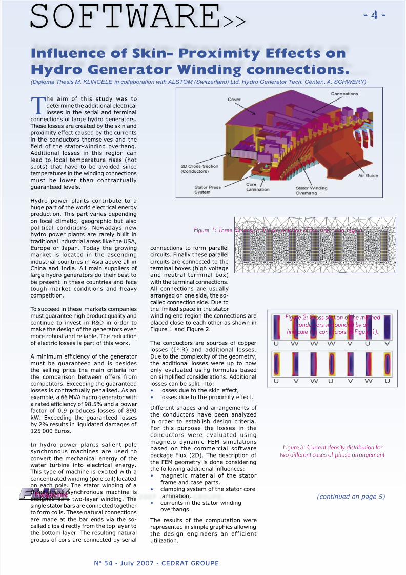
Figure 1: Three dimensional representation of the stator end region.
Figure 2: Cross section of the meshedconductors surrounded by air
(indicate the conductors in Figure 1).
Figure 3: Current density distribution for two different cases of phase arrangement.
(continued on page 5)
8/6/2019 FluxMag54 Hydro Generator Skin Effect
http://slidepdf.com/reader/full/fluxmag54-hydro-generator-skin-effect 2/3
- 5 -SOFTWARE>>
N° 54 - July 2007 - CEDRAT GROUPE.
Influence of Skin- Proximity Effects on
Hydro Generator Winding... (continued) (Diploma Thesis M. KLINGELE in collaboration with ALSTOM (Switzerland) Ltd. Hydro Generator Tech. Center., A. SCHWERY)
3D geometry and corresponding 2D
model
A three dimensional model of a stator
section is shown in Figure 1. Containing
the metallic parts such as the stator
frame, air-guides and the clamping
system of the stator core are shown. A
FEM model of the cross section of the
conductors without the frame and the
stator-winding overhang is displayed in
Figure 2. The distribution of the stator
bars corresponding to one phase in the
stator slots forms a repetitive pattern on
a part of the circumference. Within this
repetitive section the distribution is not
regular. Consequently depending on the
considered position of the 2D model on
the circumference of the stator, different
phase arrangements of the connecting
conductors are possible.
Figure 3 shows for example the
computed current density distribution
in the conductors for two different phase
arrangements corresponding to two
different positions on the circumference
of the machine. Regarding the generated
losses the upper phase arrangement is
the worst case and the lower phasearrangement the best case for all
phase arrangements of the considered
machine.
The loss factor kr is given by the ratioof the AC losses and the DC losses of
the arrangement. In the case of an
arrangement with n conductors, the
average loss factor for the considered
set of conductors is more significant.
This formula is based on the assumption
that each conductor leads the same RMS
current |I1| = … = |I2|. To compute the
loss factor it is necessary to calculate theAC losses in all conductors considering
the actual alternating currents in the
model. The losses due to the direct
current are PDC = R DC.I² , where the
resistance is given by R DC = ρCu.L/A.L
is the length, ρCu the resistivity of
copper and A the cross section of the
conductor.
The first calculations are performed on
the basic model shown in Figure 2.We
found out that it is necessary to check
the influence of the conductive metallic
parts in the vicinity of the conductors.
The solid metallic parts can have an
important influence on eddy currentsgenerated by the end region fields.
Therefore a detailed model considering
the solid metallic parts was derived
from the 3D-geometry (see Figure 1).
This extended model contains magnetic
and conducting parts located nearby the
conductors.
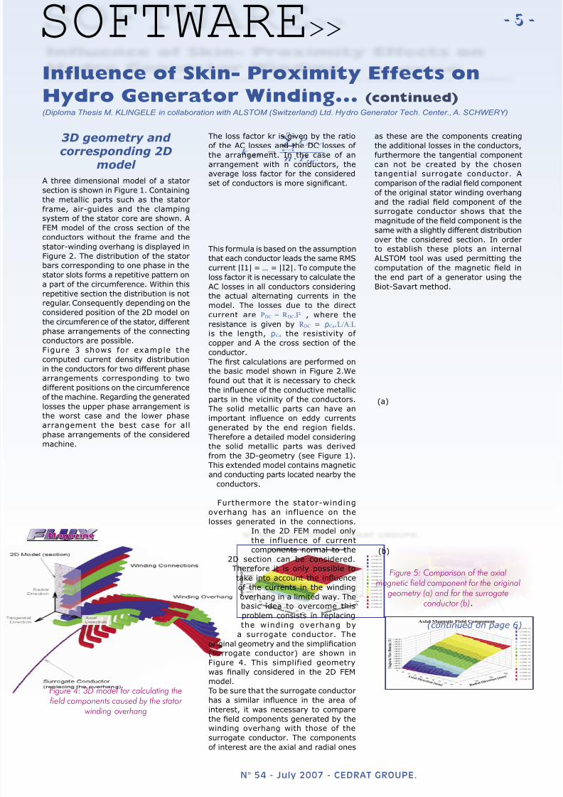
Furthermore the stator-winding
overhang has an influence on the
losses generated in the connections.
In the 2D FEM model only
the influence of current
components normal to the
2D section can be considered.Therefore it is only possible to
take into account the influence
of the currents in the winding
overhang in a limited way. The
basic idea to overcome this
problem consists in replacing
the winding overhang by
a surrogate conductor. The
original geometry and the simplification
(surrogate conductor) are shown in
Figure 4. This simplified geometry
was finally considered in the 2D FEM
model.
To be sure that the surrogate conductor
has a similar influence in the area of interest, it was necessary to compare
the field components generated by the
winding overhang with those of the
surrogate conductor. The components
of interest are the axial and radial ones
as these are the components creatingthe additional losses in the conductors,
furthermore the tangential component
can not be created by the chosen
tangential surrogate conductor. A
comparison of the radial field component
of the original stator winding overhang
and the radial field component of the
surrogate conductor shows that the
magnitude of the field component is the
same with a slightly different distribution
over the considered section. In order
to establish these plots an internal
ALSTOM tool was used permitting the
computation of the magnetic field in
the end part of a generator using theBiot-Savart method.
Figure 4: 3D model for calculating the
field components caused by the stator winding overhang
Figure 5: Comparison of the axialmagnetic field component for the original
geometry (a) and for the surrogateconductor (b).
(a)
(b)
(continued on page 6)
8/6/2019 FluxMag54 Hydro Generator Skin Effect
http://slidepdf.com/reader/full/fluxmag54-hydro-generator-skin-effect 3/3
- 6 -SOFTWARE>>
N° 54 - July 2007 - CEDRAT GROUPE.
Influence of Skin- Proximity Effects on
Hydro Generator Winding... (continued) (Diploma Thesis M. KLINGELE in collaboration with ALSTOM (Switzerland) Ltd. Hydro Generator Tech. Center., A. SCHWERY)
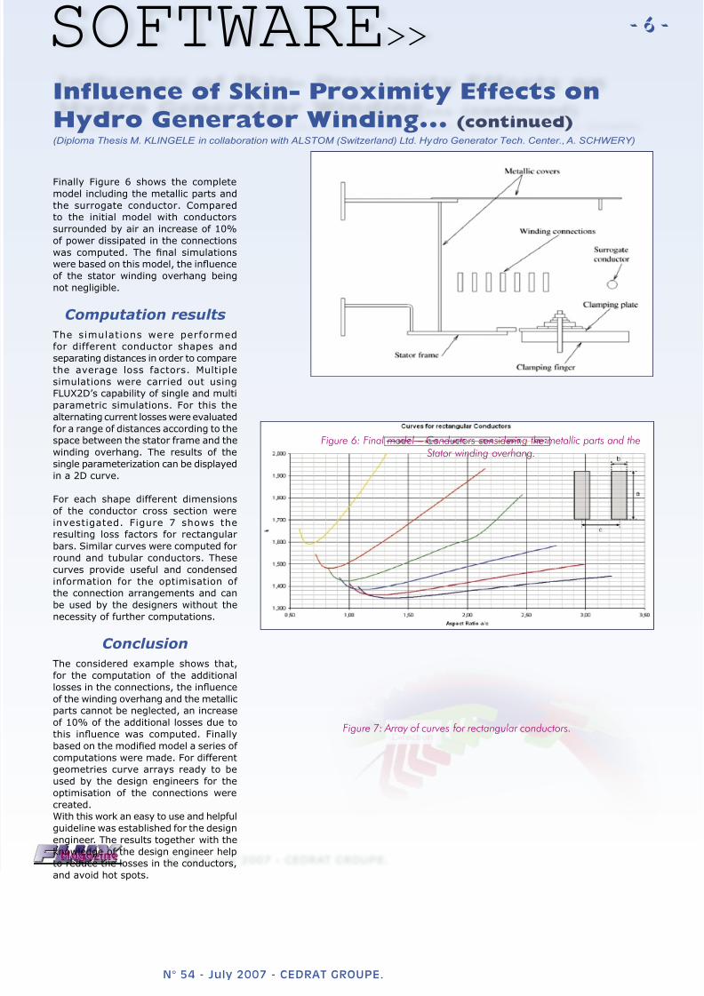
Finally Figure 6 shows the complete
model including the metallic parts and
the surrogate conductor. Compared
to the initial model with conductors
surrounded by air an increase of 10%
of power dissipated in the connections
was computed. The final simulations
were based on this model, the influence
of the stator winding overhang being
not negligible.
Computation results
The simulations were performed
for different conductor shapes andseparating distances in order to compare
the average loss factors. Multiple
simulations were carried out using
FLUX2D’s capability of single and multi
parametric simulations. For this the
alternating current losses were evaluated
for a range of distances according to the
space between the stator frame and the
winding overhang. The results of the
single parameterization can be displayed
in a 2D curve.
For each shape different dimensions
of the conductor cross section were
investigated. Figure 7 shows theresulting loss factors for rectangular
bars. Similar curves were computed for
round and tubular conductors. These
curves provide useful and condensed
information for the optimisation of
the connection arrangements and can
be used by the designers without the
necessity of further computations.
Conclusion
The considered example shows that,
for the computation of the additional
losses in the connections, the influence
of the winding overhang and the metallicparts cannot be neglected, an increase
of 10% of the additional losses due to
this influence was computed. Finally
based on the modified model a series of
computations were made. For different
geometries curve arrays ready to be
used by the design engineers for the
optimisation of the connections were
created.
With this work an easy to use and helpful
guideline was established for the design
engineer. The results together with the
knowledge of the design engineer help
to reduce the losses in the conductors,
and avoid hot spots.
Figure 7: Array of curves for rectangular conductors.
Figure 6: Final model – Conductors considering the metallic parts and theStator winding overhang.