Fluid System 04-Centrifugal Pump
46
Dr. Ir. Harinaldi, M.Eng Mechanical Engineering Department Faculty of Engineering University of Indonesia Centrifugal PUMP
-
Upload
fuad-alhamid -
Category
Documents
-
view
272 -
download
3
description
Fluid System 04-Centrifugal Pump
Transcript of Fluid System 04-Centrifugal Pump

Dr. Ir. Harinaldi, M.EngMechanical Engineering Department
Faculty of Engineering University of Indonesia
Centrifugal PUMP

Pumping System in an Pumping System in an IndustryIndustry
Centrifugal Pump

Construction and ComponentConstruction and Component

0.00001 0.0001 0.001 0.01 0.1 1 10 100 10000.01
0.1
1
10
100
1000
①②
③④
⑤
⑥
Flow rate Q(m3/min)
Tota
l hea
d H
(m)
disk friction micro pump
Centrifugal pump
Multistage centrifugal pump
Small scale pump
Double suction volute pump
Mixed flow pump
Axial flow pump
Fig. 24 Total Head

in
out
s 1 mm
disk ɸ 50 mm
Fig.25 Disk Friction Pump

Fig.27 Head and efficiency of disk friction pump
D2=50mm, N=3000rpm
100 200 300 400 500
1
2
0
20
40
60
0
H(m
)
Q(ml/min)
η(%
)
D2 = 50mm
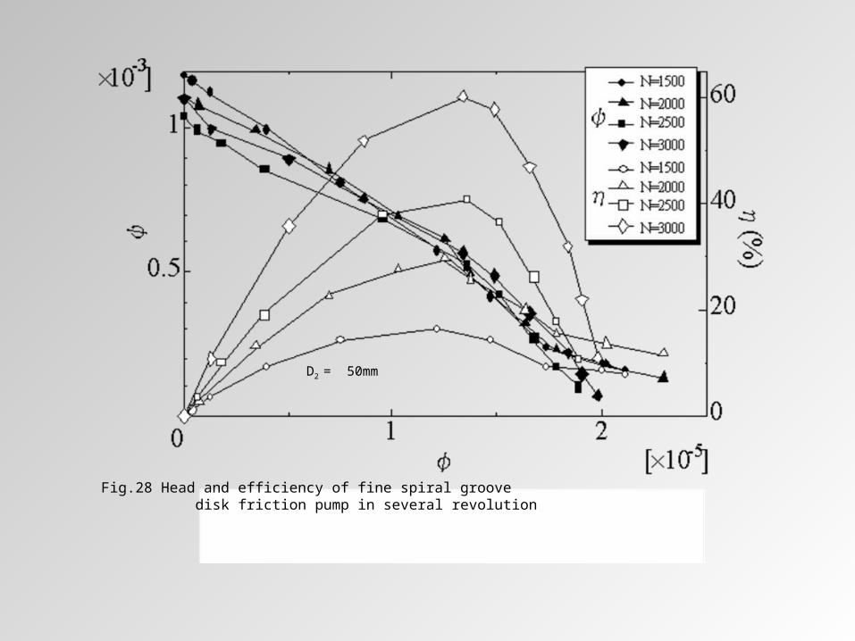
Fig.28 Head and efficiency of fine spiral groove disk friction pump in several revolution
D2 = 50mm

CasingCasing
Volute- area enlarge along flow direction- create uniform velocity distributionDiffuser- large size centrifugal pump- guide vanes surround the impeller- fluid flow decelerated while directed to enter the volute

Working PrinciplesWorking Principles
Fluid
Kin
etic
ene
rgy
pressure

InstallationInstallation
iii Zg
V
g
p
2
2
Inlet head :
ooo Zg
V
g
p
2
2
Outlet head : Total head developed by the pump:
ioioio ZZ
g
VV
g
ppH
2
22
outinfofis
s
hhhhH
lossesHH
H = manometric headhfi = friction loss at inlethfi = friction loss at outlethin= inlet losshout = outlet loss

ImpellerImpellerTheoretical Assumptions: No tangential flow in
the blade passage Impeller blades are
infinitely thin No Velocity variation
across impeller width Analysis only at inlet
and outlet Radial inlet flow


21
22
21
22
21
22
1122
2
1 WWUUCC
g
g
CUCUEh xx
Flow Capacity/Flow Rate
Head and Flow Capacity H - QHead and Flow Capacity H - QTheoretical Head Rise / Euler Head
222111 22 bCrbCrQ rr

slip
2
'2
:
x
xs C
C
factorslip

STODOLA PROPOSAL
eCx

STODOLA PROPOSALIf the number of blades is Z, and impeller circumference is 2r2 then the distance between blades is 2r2/Z = 2e/sin Then :

Other Slip FactorStodola 20o < < 30o
222
2
cot1
sin1
UCZ rs
Buseman 30o < < 80o
122
222
222
and , offunction are and
cot1
cot
rrZBA
UC
UCBA
r
rs
Stanitz 80o < < 90o
222 cot1
63.01
UCZ rs

ExampleExampleThe impeller of a centrifugal pump has backward-facing blades inclined at 30o to the tangent at impeller outlet. The blades are 20 mm in depth at the outlet, the impeller is 250 mm in diameter and it rotates at 1450 rpm. The flow rate through the pump is 0.028 m3/s and a slip factor of 0.77 may be assumed. Assume also the blades of infinitesimal thickness. Determine the theoretical and actual head developed by the impeller, and the number of impeller blades
Solution:
Flow Capacity/Flow Rate
m/s 78.1
02.025.0028.0
2
2
222
222
r
r
r
r
C
C
bDQC
bCDQ
For ideal outlet velocity triangle = 30o
m/s 08.330tan/78.130tan22 oorx CW

m/s 92.1508.319
m/s 1960/145025.060
222
22
xx WUC
NDU
Theoretical (Euler) head
(ans.) m 83.30
81.9
92.1519
) (0 11122
E
inletatradiallyentersflowCg
CUCUE x
xx
Actual head with slip
(ans.) m 74.2383.3077.0.
. 2'2
EE
CC
sN
xsx
Number of blade
(ans.) 815.8
30cot1978.1130sin177.0
cot1sin1 2222
Z
Z
UCZoo
rs

Pump LossesPump Losses1. Mechanical friction power
loss, Pm
2. Impeller (Disc) friction power loss, Pi
3. Leakage and recirculation power loss, Pl
4. Casing power loss, Pc

Pump LossesPump Losses1. Mechanical friction power loss, Pm

Pump LossesPump Losses2. Impeller (Disc) friction power loss, Pi
Head loss : hi
Flow rate : QiPi = g Qi hi

Pump LossesPump Losses3. Leakage and recirculation power loss, Pl
Head across impeller : Hi
Leakage flow rate : q = Qi - QPl = g qi Hi

Pump LossesPump Losses4. Casing power loss, Pc
Head loss : hc
Flow rate : Q Pc = g Qhc

Pump Losses Pump Losses H-Q DiagramH-Q Diagram

EfficiencyEfficiency
so P
gQH inputpower shaft
pumpby developedpower FluidEfficiency Overall
iic H
H
gQH
gQH
loss Leakage-impellerby developedpower Fluid
outlet casingat power Fluid
inlet casingat power Fluid
outlet casingat power FluidEfficiency Casing
iv Q
Q
Q
impeller through rate Flow
pump through rate FlowEfficiency Volumetric

EfficiencyEfficiency
ii
i
iii
iii hH
H
hHgQ
HgQ
lossimpeller impellerby developedpower Fluid
exitimpeller at power Fluid
impeller tosuppliedpower Fluid
exitimpeller at power FluidEfficiencyImpeller
s
iiim P
HhgQ
shaft theinput toPower
impeller tosuppliedpower FluidEfficiency Mechanical
E
H
hH
H
iiH
impellerby developed head lTheoretica
pumpby developed head ActualEfficiency Hydraulic
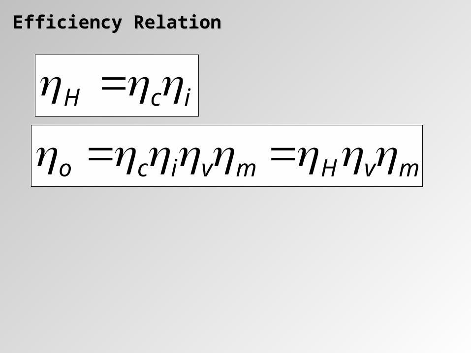
Efficiency RelationEfficiency Relation
icH
mvHmvico

Pump Shaft Power, Pump Shaft Power, PPss QHqHQhQhgPP iciims
Driven Motor Shaft Power, Driven Motor Shaft Power, PPMMTransmission Efficiency, Transmission Efficiency, TT
MTs PP T
SM
PP

Pump’s Characteristic CurvePump’s Characteristic Curve
QKKE
gAQUUE
21
222
cot
sN QKKE 21
flowratedesignisQ
where
QQKh
D
Dshock
:
23
24QKh f

Effect of Flow Rate VariationEffect of Flow Rate VariationInlet velocity
Outlet velocity
Q ; H Q ; H

Effect of Blade Outlet AngleEffect of Blade Outlet Angle2222 cot rx CUC
bQaHgAQUgUE
gCUUE r
2222
2222
cot
cot
ofor 90 2
ofor 90 2 aH
ofor 90 2 bQaH

Effect of Blade Outlet AngleEffect of Blade Outlet AngleTheoretical characteristic curves
Actual characteristic curves

Flow in the Discharge CasingFlow in the Discharge CasingVolute Casing
Function:1. Collector2. Diffuser
Deviation in capacity from the design condition will result in a radial thrust (P):
2
22
136.0:
495
DQQKwhere
BKHDP
Function:P = radial force (N)H = Head (m)D2 = peripheral diameter (m)B2 = impeller width (m)Circular section to
reduce losses due to friction and impact

Flow in the Discharge CasingFlow in the Discharge CasingVaneless Diffuser

Flow in the Discharge CasingFlow in the Discharge CasingVaneless Diffuser Continuity:
222222 rrr CbrCrbACm rbCbrC rr 2222
Conservation of angular momentum:
rxxx CCusuallyrrCC 22
Then: xCC
rrCC x 22 Radius, r Outlet kinetic energi
'tan'tan 222 consCC rx
dr
rd 'tan
22 ln'tan rr Then:
diffuserofangle

Flow in the Discharge CasingFlow in the Discharge CasingVaned Diffuser
Number of vanes on the diffuser ring:
Greater number better diffusion but more friction loss
Square cross section of diffuser channel max rh
Number of diffuser vanes have no common factor with the number of impeller
Higher rate Shorter length Higher efficiency
Able to diffuse the outlet kinetic energy at:

Flow in the Discharge CasingFlow in the Discharge CasingContribution of each section of the pump to total head

Cavitation in PumpsCavitation in PumpsVapour bubbles formation of the liquid as the local absolute static pressure of a liquid falls below the vapour pressure
occurs mainly at the suction side (at the eye of impeller as the velocity increases and pressure decreases)
Local pitting of impeller cavitation erosion Noise Decrease pump efficiency

Net Positive Suction Head (NPSH)Net Positive Suction Head (NPSH)
The difference of total suction head in the impeller inlet side (impeller eye) above the vapour pressure
absolutearepressuresallg
p
g
V
g
pNPSH vapii
2
2
A measure of the energy available on the suction side of the pump
A measure to indicate the occurrence of cavitation
Cavitation Parameter (Toma Cavitation Number)
H
g
p
gV
gp
pumpbyDevelopedHead
NPSHvapii
2
2

NPSH Required (NPSHR) Net Suction Head as required by the
pump in order to prevent cavitation for safe and reliable operation of the pump.
The required NPSHR for a particular pump is in general determined experimentally by the pump manufacturer (will vary depending on the size and speed of the pump) and a part of the documentation of the pump.
Net Positive Suction Head (NPSH)Net Positive Suction Head (NPSH)
Measurement of NPSHR by 3% head reduction
Example of pump documentation

NPSH Available (NPSHA) The Net Positive Suction Head
made available the suction system for the pump.
The NPSHA can be determined during design and construction, or determined experimentally from the actual physical system and calculated with the Energy Equation
Net Positive Suction Head (NPSH)Net Positive Suction Head (NPSH)
Energy at 1 = Energy at 2 + Energy lost between 1 and 2
inletinlet losseszg
p
g
V
g
plosess
g
V
g
pz
g
p1
12
222
221
1
22
At inlet p2 = pi ; V2 = Vi and lossesinlet = hin + hfi, then:
NPSH available at impeller inlet :
fiivap
A hhzg
p
g
pNPSH 1
1

To avoid cavitation in a pump operation
Cavitation ~ NPSHCavitation ~ NPSH
RA NPSHNPSH RA or

Suction Specific SpeedSuction Specific SpeedA function due to cavitation that influences the efficiency
4/3
2/1
NPSHg
NQN suc
Dimensionless suction specific speed
sucNf ,
4/34/3
4/3
H
NPSH
N
N
suc
s
Cavitation parameter
212
212
212
1 DDNNNPSH
NPSH
Similarity Laws

ExampleExampleWhen a laboratory test was carried out on a pump, it was found that, for a pump total head of 36 m at discharde of 0.05 m3/s, cavitation began when the sum of the static pressure plus the velocity head at inlet was reduced to 3.5 m. The atmospheric pressure was 750 mmHg and the vapour pressure of water 1.8 kPa. If the pump is to operate at a location where atmospheric pressure is reduced to 620 mmHg and the vapour pressure of water is 830 Pa, what is the value of the cavitation parameter when the pump develops the same total head and discharge? Is it necessary to reduce the height of the pump above the supply, and if so by how much?