Fluid Power Generation & Transportation Systems for Longwalls
6
Fluid Power Generation & Transportation Systems for Longwalls Thomas L. Hutchinson, PE Morgantown Machine & Hydraulics Swanson Industries Morgantown, West Virginia USA Abstract—We review the recent history of longwall mining in the USA by comparing the typical 1980’s longwall section to a typical 2010’s longwall section. By comparing the trends, we have identified how the increases in production levels drive the services equipment suppliers to innovative developments in the generation and distribution of fluid power to the longwall section. Some of the problems involved with the longwall services keeping pace with the demand involve overcoming constraints that are unique to mining. As noted, to date the improvements in the fluid power systems are reactive, being driven by the demand. Such being the case, fluid power systems are lagging behind the demand and the need to be proactive in fluid power system design is brought to light. I. INTRODUCTION Providing adequate volume of fluid, both emulsion for hydraulic power and water for cooling and dust suppression, is an on-going need in the longwall mining industry. Let’s focus on the emulsion system primarily and the water system will follow. Gross deficiency in the volume being delivered to the longwall face equipment is easily noticed in that the roof supports slow down and fail to keep pace with the mining machine. Lesser deficiencies are the real danger in that they can go unnoticed. When the volume fails to meet the demand, the result is lower pressure. Low pressure in the system is the major problem. It is basic that low setting pressure on the longwall face results in poor roof control. A properly designed fluid power system is critical to the successful and efficient operation of the longwall. The additional fluid required to keep pace with the mining rate and, thus, keep the supply pressure up to standards is simple, right? All that is needed is to add more pumps or larger pumps. Problem solved, right? Not quite. The fluid volume is available at the pump station. That is the easy part. The user of this fluid is located 2000 to 3000 feet (600 to 900 meters) away from the pumps. The hydraulic lines connecting the pumps to the longwall face should be designed to deliver the fluid with minimal line losses. As the longwall production rates increase, there is more system designing involved than just the hydraulic lines. The electric power cables, after briefly decreasing in size due to the increase in voltage, are increased in size and number. The belt conveying equipment is increased in size and speed. The increased dimensional demands cannot be met in many instances for the simple reason that in mining, additional space is not an option. The width and height of the access entry is fixed by geologic conditions. As a result, there are quite a few innovations that help with the problem of keeping the longwall section running in a productive, efficient manner. We present several examples of what is being done to address this need. - Examples of modern, high capacity emulsion pump stations and improved pump controls. - Examples of innovative monorail concepts that help address the balance between the need for more fluid conduit capacity and the limited space available in the main access entry. - Examples of how the combining of monorail and pump systems can address the pressure demands on the longwall face. - A critical example of one proactive method for addressing the pressure losses in fluid systems. II. BRIEF REVIEW OF LONGWALL TRENDS Table I shows a comparison of the typical longwall situation in the early 1980’s and the typical longwall situation today. The table is not intended to show absolute, hard numbers due to the wide range of values to be shown. The table is meant to quantify the trends. From the table it is clear that the demands on the longwall services has more than tripled and there is no reason to believe further increases are not forthcoming.
Transcript of Fluid Power Generation & Transportation Systems for Longwalls

Fluid Power Generation & Transportation Systems for Longwalls
Thomas L. Hutchinson, PE
Morgantown Machine & Hydraulics Swanson Industries
Morgantown, West Virginia USA
Abstract—We review the recent history of longwall mining in the USA by comparing the typical 1980’s longwall section to a typical 2010’s longwall section. By comparing the trends, we have identified how the increases in production levels drive the services equipment suppliers to innovative developments in the generation and distribution of fluid power to the longwall section. Some of the problems involved with the longwall services keeping pace with the demand involve overcoming constraints that are unique to mining. As noted, to date the improvements in the fluid power systems are reactive, being driven by the demand. Such being the case, fluid power systems are lagging behind the demand and the need to be proactive in fluid power system design is brought to light.
I. INTRODUCTION Providing adequate volume of fluid, both emulsion for
hydraulic power and water for cooling and dust suppression, is an on-going need in the longwall mining industry. Let’s focus on the emulsion system primarily and the water system will follow. Gross deficiency in the volume being delivered to the longwall face equipment is easily noticed in that the roof supports slow down and fail to keep pace with the mining machine. Lesser deficiencies are the real danger in that they can go unnoticed. When the volume fails to meet the demand, the result is lower pressure. Low pressure in the system is the major problem.
It is basic that low setting pressure on the longwall face results in poor roof control. A properly designed fluid power system is critical to the successful and efficient operation of the longwall.
The additional fluid required to keep pace with the mining rate and, thus, keep the supply pressure up to standards is simple, right? All that is needed is to add more pumps or larger pumps. Problem solved, right? Not quite. The fluid volume is available at the pump station. That is the easy part. The user of this fluid is located 2000 to 3000 feet (600 to 900 meters) away from the pumps. The hydraulic lines connecting the pumps to the longwall face should be designed to deliver the fluid with minimal line losses.
As the longwall production rates increase, there is more system designing involved than just the hydraulic lines. The electric power cables, after briefly decreasing in size due to the increase in voltage, are increased in size and number. The belt conveying equipment is increased in size and speed. The increased dimensional demands cannot be met in many instances for the simple reason that in mining, additional space is not an option. The width and height of the access entry is fixed by geologic conditions. As a result, there are quite a few innovations that help with the problem of keeping the longwall section running in a productive, efficient manner.
We present several examples of what is being done to address this need.
- Examples of modern, high capacity emulsion pump stations and improved pump controls.
- Examples of innovative monorail concepts that help address the balance between the need for more fluid conduit capacity and the limited space available in the main access entry.
- Examples of how the combining of monorail and pump systems can address the pressure demands on the longwall face.
- A critical example of one proactive method for addressing the pressure losses in fluid systems.
II. BRIEF REVIEW OF LONGWALL TRENDS Table I shows a comparison of the typical longwall
situation in the early 1980’s and the typical longwall situation today. The table is not intended to show absolute, hard numbers due to the wide range of values to be shown. The table is meant to quantify the trends.
From the table it is clear that the demands on the longwall services has more than tripled and there is no reason to believe further increases are not forthcoming.
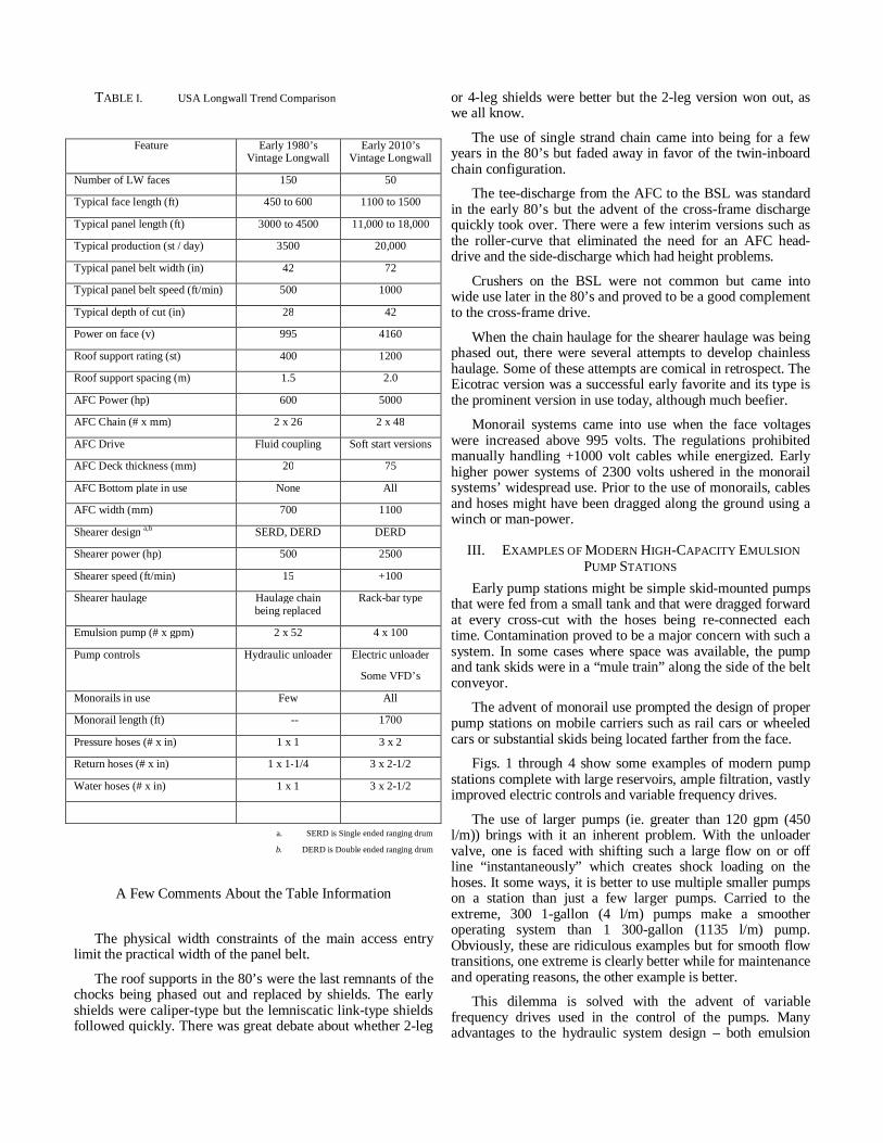
TABLE I. USA Longwall Trend Comparison
Feature Early 1980’s
Vintage Longwall Early 2010’s
Vintage Longwall
Number of LW faces 150 50
Typical face length (ft) 450 to 600 1100 to 1500
Typical panel length (ft) 3000 to 4500 11,000 to 18,000
Typical production (st / day) 3500 20,000
Typical panel belt width (in) 42 72
Typical panel belt speed (ft/min) 500 1000
Typical depth of cut (in) 28 42
Power on face (v) 995 4160
Roof support rating (st) 400 1200
Roof support spacing (m) 1.5 2.0
AFC Power (hp) 600 5000
AFC Chain (# x mm) 2 x 26 2 x 48
AFC Drive Fluid coupling Soft start versions
AFC Deck thickness (mm) 20 75
AFC Bottom plate in use None All
AFC width (mm) 700 1100
Shearer design a,b SERD, DERD DERD
Shearer power (hp) 500 2500
Shearer speed (ft/min) 15 +100
Shearer haulage Haulage chain being replaced
Rack-bar type
Emulsion pump (# x gpm) 2 x 52 4 x 100
Pump controls Hydraulic unloader Electric unloader
Some VFD’s
Monorails in use Few All
Monorail length (ft) -- 1700
Pressure hoses (# x in) 1 x 1 3 x 2
Return hoses (# x in) 1 x 1-1/4 3 x 2-1/2
Water hoses (# x in) 1 x 1 3 x 2-1/2
a. SERD is Single ended ranging drum
b. DERD is Double ended ranging drum
A Few Comments About the Table Information
The physical width constraints of the main access entry limit the practical width of the panel belt.
The roof supports in the 80’s were the last remnants of the chocks being phased out and replaced by shields. The early shields were caliper-type but the lemniscatic link-type shields followed quickly. There was great debate about whether 2-leg
or 4-leg shields were better but the 2-leg version won out, as we all know.
The use of single strand chain came into being for a few years in the 80’s but faded away in favor of the twin-inboard chain configuration.
The tee-discharge from the AFC to the BSL was standard in the early 80’s but the advent of the cross-frame discharge quickly took over. There were a few interim versions such as the roller-curve that eliminated the need for an AFC head-drive and the side-discharge which had height problems.
Crushers on the BSL were not common but came into wide use later in the 80’s and proved to be a good complement to the cross-frame drive.
When the chain haulage for the shearer haulage was being phased out, there were several attempts to develop chainless haulage. Some of these attempts are comical in retrospect. The Eicotrac version was a successful early favorite and its type is the prominent version in use today, although much beefier.
Monorail systems came into use when the face voltages were increased above 995 volts. The regulations prohibited manually handling +1000 volt cables while energized. Early higher power systems of 2300 volts ushered in the monorail systems’ widespread use. Prior to the use of monorails, cables and hoses might have been dragged along the ground using a winch or man-power.
III. EXAMPLES OF MODERN HIGH-CAPACITY EMULSION PUMP STATIONS
Early pump stations might be simple skid-mounted pumps that were fed from a small tank and that were dragged forward at every cross-cut with the hoses being re-connected each time. Contamination proved to be a major concern with such a system. In some cases where space was available, the pump and tank skids were in a “mule train” along the side of the belt conveyor.
The advent of monorail use prompted the design of proper pump stations on mobile carriers such as rail cars or wheeled cars or substantial skids being located farther from the face.
Figs. 1 through 4 show some examples of modern pump stations complete with large reservoirs, ample filtration, vastly improved electric controls and variable frequency drives.
The use of larger pumps (ie. greater than 120 gpm (450 l/m)) brings with it an inherent problem. With the unloader valve, one is faced with shifting such a large flow on or off line “instantaneously” which creates shock loading on the hoses. It some ways, it is better to use multiple smaller pumps on a station than just a few larger pumps. Carried to the extreme, 300 1-gallon (4 l/m) pumps make a smoother operating system than 1 300-gallon (1135 l/m) pump. Obviously, these are ridiculous examples but for smooth flow transitions, one extreme is clearly better while for maintenance and operating reasons, the other example is better.
This dilemma is solved with the advent of variable frequency drives used in the control of the pumps. Many advantages to the hydraulic system design – both emulsion

and water – are realized in the use of VFD’s. The advantages include a) Less wasted energy, b) Less turbulence in the emulsion tank, c) Better control over the pressure regulation and d) Less hydraulic shock to the system during loading and unloading.
Figure 1. Track-Mounted Pump Car
Fig. 1 shows a modern, track-mounted pump car. Note the VFD control cabinet on the left end of the car. This car is one of three cars making up the entire pump station.
The question of whether to mix emulsion on site (at the pump station) or mix on the surface continues to be debated. The best results in quality of the mix and cleanliness are obtained by using a central mixing station where the water and neat oil quality is better controlled and filtration can be effected better.
Figure 2. Track-Mounted Tank Car
Fig. 2 shows a modern, rail-mounted tank car. Note the space-saving in-tank return filters, boost pumps and incoming emulsion filter. In this installation, the mixed emulsion is prepared on the surface and piped to the pump station. The filter is provided to avoid contamination that might be introduced into the system from the supply line.
The pump car(s) and tank car shown above will form a complete pump station such as is depicted in Fig. 3.
Figure 3. Track-Mounted Pump Station
The use of VFD’s in controlling emulsion pumps and water pumps is going to be standard in the future because the advantages out-weigh any additional initial cost. Several versions of the VFD are in use today. Fig. 4 shows a liquid-cooled VFD cabinet neatly mounted within a pump carrier frame which can be suspended from the monorail system.
Figure 4. Liquid-Cooled VFD
IV. EXAMPLES OF INNOVATIVE MONORAIL SYSTEMS As mentioned, the monorail system is born of necessity
due to the advent of +1000 volt power cables to the face. The longwall power centers getting larger and more difficult to move provides the incentive to maximize the power move distance. The power cable length is determined by the electric regulations and deals with the distance between connections. Since the net travel of the monorail is determined by the difference between the extended length and the retracted length the maximum power move distance is enhanced by making the overall system longer.
So far, we have larger cables, more cables and wider belt conveyors all within an entry whose width cannot be increased. All these factors combine to restrict the space available for the hydraulic hoses. Now, to maximize the power move distance, the hose lengths are going to be increased.

But wait! Did we not already decide that more flow (read as pressure) is needed to feed the production machines and to maintain good roof conditions on the longwall face? Making the hoses longer goes counter to this goal.
The challenge has been made. Who will answer the challenge?
Side-By-Side Monorail Several innovations have been made in this area. Fig. 5
shows a unique method whereby the fluid is transmitted by pipes from the pumps to the face area.
Figure 5. Side-by-Side Monorail
The side-by-side monorail utilizes pipes in lieu of hoses to carry the emulsion and the water. There is a slight advantage in the pipe based on its having a more favorable friction factor and the lack of loops in the line. However, the big advantage is the fact that the pipe is more compact than a comparable number of hoses.
Since the cables are carried by a separate, parallel monorail, there is the disadvantage with this system of the need to install two sets of rails. Nevertheless, this system addresses the problem of pressure loss in the face feed very well and has been used numerous times in recent history.
Over-Under Monorail Another variant of the pipe monorail is the Over-Under
Monorail. This version addresses the negative feature of the need for a second, parallel rail. Figs. 6 & 7 show an over-under monorail in use.
The pipes being overhead and the cables on a separate rail beneath allows the operation to function quite well. While there is a second rail, it need not be handled repeatedly after the initial installation. There are several installations in operation using the Over-Under Monorail concept.
Figure 6. Over-Under Monorail
In Fig. 6, note the pipes overhead and the cable trolleys operating on the lower rail making the cable movements totally independent of the pipe movements.
Figure 7. Over-Under Monorail
In Fig. 7, it can be seen that the area of the overhead pipes outbye the power cross-cut results in the bottom rail being vacant until the next power move.
Multiple Layer Monorail While nothing new, installing cables and hoses on multiple
layered pockets allows for additional or large sized items to be installed on monorail trolleys while not increasing the width of the monorail system. This method can be used with no consequences when the entry height is ample. Even in restricted height conditions, this method of operation can be effected by merely decreasing the extended distance of the trolleys to account for the lower mounting of the bottom loops. Figs. 8 & 9 depict a 2-tiered monorail trolley.
In Fig. 8, note there are numerous large hoses mounted on the lower tier. Having the second tier eliminates the need to make the trolleys wider and helps with balancing the system.

Figure 8. Two-Tiered Monorail Trolley
Fig. 9 is showing a two-tiered monorail trolley that is used in a lower seam where the width of the system is limited by physical constraints.
Figure 9. Two-Tiered Monorail Trolley
Another Innovation Upgraded From the Past Again, while not new, the use of multiple traction units to
move sections of the monorail system is enjoying renewed interest in the USA. The method – common in Australia – involves dividing the monorail trolleys into sections that are moved along by air or hydraulically powered traction units. When used in conjunction with cable break points, this system allows increased power move distances by breaking off sections of the monorail and moving them outbye the power center cross-cut, even allowing them to be set-up for the next power move ahead of time.
Fig. 10 shows a hydraulically-powered traction unit that is used to move sections of the trolleys along the monorail.
Figure 10. Traction Unit for Monorails
So, the few innovations made recently to address the need for more hoses and larger hoses while confined by a fixed entry-width dimension are very effective, but the long distance from the pumps to the face still is an obstacle. When the extended face length is added to the long monorail length, we are looking at up to 3000 ft (900 meters) from the pumps to the last shield on the face. That’s over ½ mile (0.9 km.)
V. EXAMPLES OF COMBINED MONORAIL AND PUMP SYSTEMS
To address the situation where the distance from the pumps to the last shields on the face is great and – if trends continue – might get greater, one approach is to move the pumps closer to the demand which is the face. But, that would be going against what we have already won. What about the longer power move distances? Such a system actually makes longer power moves even more feasible.
Pumps and Tanks on the Monorail Where the entry width permits, there are several instances
where the pumps have been installed on the monorail resulting in several advantages, namely
- Greatly reduced line losses in the pressure lines,
- Greatly reduced line losses in the return lines,
- Reduced response time of the pumps,
- No time consumed moving the pumps during “power moves,” and
- Better fluid cleanliness since no lines need to be parted during power moves.
If geological conditions permit, hanging the pumps on the monorail addresses every fluid problem that has been discussed so far. Fig. 11 shows a pump system in operation in the USA and depicts the pump cabinet on a monorail in the section belt entry about 200 ft (50 m) from the face.
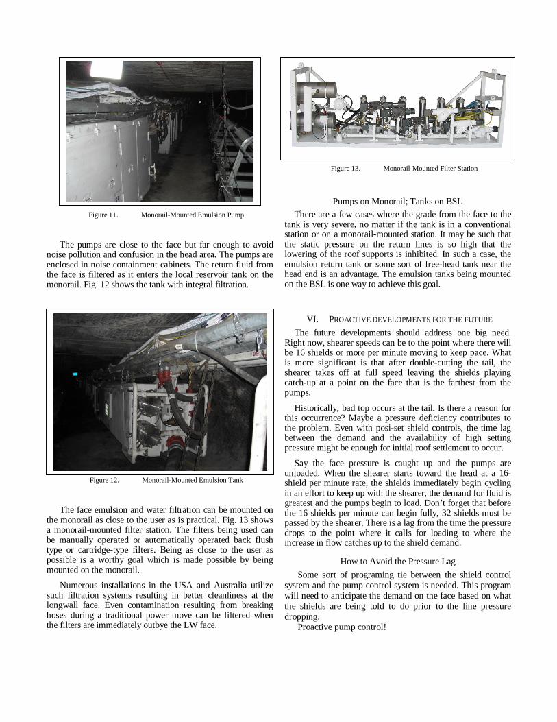
Figure 11. Monorail-Mounted Emulsion Pump
The pumps are close to the face but far enough to avoid noise pollution and confusion in the head area. The pumps are enclosed in noise containment cabinets. The return fluid from the face is filtered as it enters the local reservoir tank on the monorail. Fig. 12 shows the tank with integral filtration.
Figure 12. Monorail-Mounted Emulsion Tank
The face emulsion and water filtration can be mounted on the monorail as close to the user as is practical. Fig. 13 shows a monorail-mounted filter station. The filters being used can be manually operated or automatically operated back flush type or cartridge-type filters. Being as close to the user as possible is a worthy goal which is made possible by being mounted on the monorail.
Numerous installations in the USA and Australia utilize such filtration systems resulting in better cleanliness at the longwall face. Even contamination resulting from breaking hoses during a traditional power move can be filtered when the filters are immediately outbye the LW face.
Figure 13. Monorail-Mounted Filter Station
Pumps on Monorail; Tanks on BSL There are a few cases where the grade from the face to the
tank is very severe, no matter if the tank is in a conventional station or on a monorail-mounted station. It may be such that the static pressure on the return lines is so high that the lowering of the roof supports is inhibited. In such a case, the emulsion return tank or some sort of free-head tank near the head end is an advantage. The emulsion tanks being mounted on the BSL is one way to achieve this goal.
VI. PROACTIVE DEVELOPMENTS FOR THE FUTURE The future developments should address one big need.
Right now, shearer speeds can be to the point where there will be 16 shields or more per minute moving to keep pace. What is more significant is that after double-cutting the tail, the shearer takes off at full speed leaving the shields playing catch-up at a point on the face that is the farthest from the pumps.
Historically, bad top occurs at the tail. Is there a reason for this occurrence? Maybe a pressure deficiency contributes to the problem. Even with posi-set shield controls, the time lag between the demand and the availability of high setting pressure might be enough for initial roof settlement to occur.
Say the face pressure is caught up and the pumps are unloaded. When the shearer starts toward the head at a 16-shield per minute rate, the shields immediately begin cycling in an effort to keep up with the shearer, the demand for fluid is greatest and the pumps begin to load. Don’t forget that before the 16 shields per minute can begin fully, 32 shields must be passed by the shearer. There is a lag from the time the pressure drops to the point where it calls for loading to where the increase in flow catches up to the shield demand.
How to Avoid the Pressure Lag Some sort of programing tie between the shield control
system and the pump control system is needed. This program will need to anticipate the demand on the face based on what the shields are being told to do prior to the line pressure dropping.
Proactive pump control!