Examination of 2-Fluid Nozzle and 3-Fluid Nozzle for Fuel ...
1. Introduction
In the continuous casting process of aluminum-killedsteel, argon gas is injected into molten steel stream to detersubmerged entry nozzle (SEN) clogging. Since both entrap-ment of the argon bubble and unstable flow induced byclogging cause the slab quality to deteriorate, the processmust be optimized to achieve high quality slab. It is essen-tial to stabilize fluid flow in the mold to produce high qual-ity steel, therefore, much research has been performed con-trolling flow pattern of the molten steel from various tech-nical aspects.1–9)
Application of electromagnetic force into molten steelflow in the mold and optimizing submerged entry nozzledesign is a possible effective measure. Various types ofstatic magnetic field (brake)3,4) and traveling magneticfield5,6) are installed into commercial continuous caster.Various designs of submerged entry nozzle are also pro-posed to optimize spouting stream from nozzle.7–9) Thoseresults are generally based on experimental study withwater model and/or numerical simulation of fluiddynamics.7–9)
Although fluid flow in the nozzle significantly effects onspouting stream as a source of mold flow, few studies havebeen done in this field.10,11) Uneven flow velocity dependingon plate sliding direction was clarified,11) however, precise
consideration of gas-liquid multi-phase-flow in numericalsimulations and replication of steel flow by water modelsare insufficient to reveal fluid flow in submerged entry noz-zle. Whether steel flow in the nozzle is potential-flow orplug-flow is still unclear.
In this study, fluid flow in the nozzle is in-situ observedby fusible alloy model and steel flow model. Subsequently,argon gas gushing out of mold meniscus is also measured atcommercial caster, to estimate net argon flow rate broughtinto nozzle. Molten steel flow condition in the nozzle ofcommercial slab continuous caster is estimated.
2. Experimental
2.1. Fusible Alloy Model
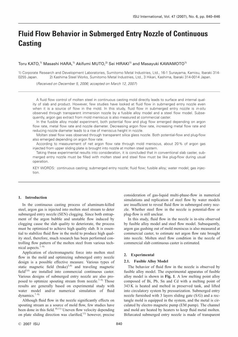
The behavior of fluid flow in the nozzle is observed byfusible alloy model. The experimental apparatus of fusiblealloy model is shown in Fig. 1. A low melting point alloycomposed of Bi, Pb, Sn and Cd with a melting point of343 K is heated and melted in preserved tank, and liftedinto circulatory system by pressurization. Submerged entrynozzle furnished with 3 layers sliding gate (S/G) and a rec-tangle mold is equipped in the system, and the metal is cir-culated by electro magnetic pump (EM pump). The channeland mold are heated by heaters to keep fluid metal molten.Bifurcated submerged entry nozzle is made of transparent
840© 2007 ISIJ
Fluid Flow Behavior in Submerged Entry Nozzle of ContinuousCasting
Toru KATO,1) Masashi HARA,1) Akifumi MUTO,2) Sei HIRAKI1) and Masayuki KAWAMOTO1)
1) Corporate Research and Development Laboratories, Sumitomo Metal Industries, Ltd., 16-1 Sunayama, Kamisu, Ibaraki 314-0255 Japan. 2) Kashima Steel Works, Sumitomo Metal Industries, Ltd., 3 Hikari, Kashima, Ibaraki 314-0014 Japan.
(Received on December 5, 2006; accepted on March 12, 2007 )
A fluid flow control of molten steel in continuous casting mold directly leads to surface and internal qual-ity of slab and product. However, few studies have looked at fluid flow in submerged entry nozzle evenwhen it is a source of flow in the mold. In this study, fluid flow in submerged entry nozzle is in-situ observed through transparent immersion nozzle by a fusible alloy model and a steel flow model. Subse-quently, argon gas extract from mold meniscus is also measured at commercial caster.
In the fusible alloy model experiment, both potential flow and plug flow emerged depending on argonflow rate, metal flow rate and nozzle diameter. Decreasing argon flow rate, increasing metal flow rate andreducing nozzle diameter leads to a rise of meniscus height in nozzle.
Molten steel flow was observed through transparent silica glass nozzle. Both potential-flow and plug-flowalso emerged depending on argon flow rate.
According to measurement of net argon flow rate through mold meniscus, about 20% of argon gas injected from upper sliding plate is brought into nozzle at molten steel system.
Taking these experimental results into consideration, it is concluded that in conventional slab caster, sub-merged entry nozzle must be filled with molten steel and steel flow must be like plug-flow during usual operation.
KEY WORDS: continuous casting; submerged entry nozzle; fluid flow; fusible alloy; water model; gas injec-tion.
ISIJ International, Vol. 47 (2007), No. 6, pp. 840–846
acrylic acid resin.The specification of this model is shown in Table 1. The
experimental apparatus is essentially 1/4 scaled model forcommercial slab caster. A basic experimental condition isselected so that Froude (Fr) number might coincide with theoperating conditions at a casting speed of 1.6 m/min. Threenozzles of different inner diameter, 22 mm, 30 mm and 40mm are applied in the experiment. The sliding gate openingratio was fixed at 67% stroke. Metal temperature is con-trolled at about 383 K in the system. Argon gas is injectedfrom upper or lower plates of sliding gate through boreswith 0.5 mm diameter. As argon gas is injected into closedchannel, all of gas injected is brought into nozzle in thissystem, different from commercial continuous caster. Influ-ences of the fluid flow rate, argon gas flow rate and nozzleinner diameter on fluid flow behavior were examined.
2.2. Molten Steel Model
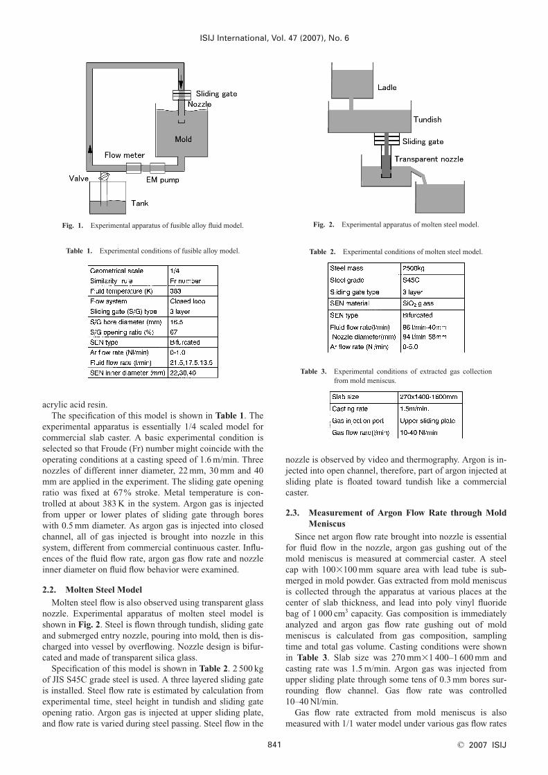
Molten steel flow is also observed using transparent glassnozzle. Experimental apparatus of molten steel model isshown in Fig. 2. Steel is flown through tundish, sliding gateand submerged entry nozzle, pouring into mold, then is dis-charged into vessel by overflowing. Nozzle design is bifur-cated and made of transparent silica glass.
Specification of this model is shown in Table 2. 2 500 kgof JIS S45C grade steel is used. A three layered sliding gateis installed. Steel flow rate is estimated by calculation fromexperimental time, steel height in tundish and sliding gateopening ratio. Argon gas is injected at upper sliding plate,and flow rate is varied during steel passing. Steel flow in the
nozzle is observed by video and thermography. Argon is in-jected into open channel, therefore, part of argon injected atsliding plate is floated toward tundish like a commercialcaster.
2.3. Measurement of Argon Flow Rate through MoldMeniscus
Since net argon flow rate brought into nozzle is essentialfor fluid flow in the nozzle, argon gas gushing out of themold meniscus is measured at commercial caster. A steelcap with 100�100 mm square area with lead tube is sub-merged in mold powder. Gas extracted from mold meniscusis collected through the apparatus at various places at thecenter of slab thickness, and lead into poly vinyl fluoridebag of 1 000 cm3 capacity. Gas composition is immediatelyanalyzed and argon gas flow rate gushing out of moldmeniscus is calculated from gas composition, samplingtime and total gas volume. Casting conditions were shownin Table 3. Slab size was 270 mm�1 400–1 600 mm andcasting rate was 1.5 m/min. Argon gas was injected fromupper sliding plate through some tens of 0.3 mm bores sur-rounding flow channel. Gas flow rate was controlled10–40 Nl/min.
Gas flow rate extracted from mold meniscus is alsomeasured with 1/1 water model under various gas flow rates
ISIJ International, Vol. 47 (2007), No. 6
841 © 2007 ISIJ
Fig. 1. Experimental apparatus of fusible alloy fluid model.
Table 1. Experimental conditions of fusible alloy model.
Fig. 2. Experimental apparatus of molten steel model.
Table 2. Experimental conditions of molten steel model.
Table 3. Experimental conditions of extracted gas collectionfrom mold meniscus.

between 12–120 Nl/min. Air is also injected from uppersliding plate, and gas volume gathered by same apparatus ismeasured without composition analysis. As gas was in-jected into closed loop, all of injected gas must be broughtinto nozzle by force, which is different from caster.
3. Experimental
3.1. Fusible Alloy Model
Examples of observed fluid flow in the nozzle by fusiblealloy model are shown in Fig. 3. Metal is flown like plug-flow under lower argon flow rate and with a narrow nozzle,as shown in Fig. 3(a), while increasing argon flow rate andexpansion of nozzle diameter make metal flow like poten-tial-flow, as shown in Fig. 3(b). Although potential-flow isunrealized with water model, it is realized with fusible alloydepending on experimental condition. The disparity mustbe caused by physical property differences such as surfacetension between gas and liquid, details will be discussedlater.
According to these experiments, meniscus height h in-side nozzle is measured under various conditions as shownin Fig. 4, in which metal flow rate and argon flow rate arevaried at a nozzle size of 30 mm in inner diameter. Al-though many splashes of metal are seen in the nozzle, metalmeniscus inside nozzle is stable enough to measure itsheight. When meniscus height is raised to the bottom ofsliding gate, metal flow condition looks like plug-flow. Bothincreasing argon gas flow rate and decreasing metal flowrate leads to a drop in meniscus height. Change in meniscusheight with argon flow rate seems almost linear under each
metal flow rate.Meniscus height measured at constant metal flow rate
under various nozzle sizes is shown in Fig. 5. Expansion ofnozzle size leads to a drop in meniscus height, and changesin meniscus height with argon flow rate seems almost linearunder each nozzle size. Argon injection location, whetherupper plate or lower plate, and direction against plate slid-ing direction did not give significant effect on the meniscusheight. It is concluded that meniscus height in submergedentry nozzle is fixed depending on metal flow rate Ql
(l/min), argon flow rate Qa (Nl/min) and nozzle diameter D(mm). The multiple regression equation deriving potentialflow length in nozzle H (mm), i.e. difference between S/Gbottom to mold meniscus distance and nozzle inside menis-cus height is obtained in the following Eq. (1).
H�15.6 ·Qa2.02·Ql
�2.80·D3.04 ....................(1)
As gas entrainment is generally represented by gas/liquidratio, Eq. (1) is modified into Eq. (2).
..................(2)
The results of this analysis predicting gas/liquid ratio com-pared with experimental results are shown in Fig. 6. Exper-iments are carried out on the condition that gas/liquid ratiois from 0.01 to 0.08. The equation gives a reasonable over-all indication of gas/liquid ratio.
Nozzle internal pressure during experiment is measured.
Q
QD Q Ha
ll� �0 257 1 51 0 38 0 49. . . .⋅
ISIJ International, Vol. 47 (2007), No. 6
842© 2007 ISIJ
Fig. 3. Behavior of fusible alloy in nozzle at metal flow rate of21.5 l/min.
Fig. 4. Effect of Ar and fluid flow rate on meniscus height innozzle at constant nozzle inner diameter of 30 mm.
Fig. 5. Effect of nozzle diameter and Ar flow rate on meniscusheight in nozzle at constant metal flow rate of 13.5 L/min.
Fig. 6. Comparison between experimental results and calculatedvalue.

A pressure gauge is set just below the lower sliding plate toavoid an effect of dynamic pressure due to fluid flow. Re-sults obtained are shown in Fig. 7. Internal pressure is alsostable enough to measure. A negative value is obtained inevery condition, and obviously relates with meniscus heightin nozzle. Furthermore, measured pressures coincide withestimated negative pressure to raise the fluid up obtained byreverse calculation from measured meniscus height. In thecalculation, density of fusible alloy is used as fluid density,instead of net density involving gas volume. Since gas vol-ume ratio is less than 0.1 as shown in Fig. 6, effect of gasshould not be significant. According to measurement withsubmerged entry nozzle and molten steel, internal pressurewas negative12,13) and became higher with an increase in gasflow rate.13) Those measured pressures are consistent withpresent data shown in Fig. 7.
3.2. Molten Steel Model
Molten steel flow observed through transparent glassnozzle, injecting argon gas from upper plate, is shown inFig. 8. The steel flows down along nozzle wall. The nozzlecould withstand thermal shock and high temperatures, andmolten steel flow, splashes and meniscus in the nozzlecould be observed through nozzle material.
The steel flow in the nozzle observed by thermography isshown in Fig. 9. These figures are taken under argon flowrate of 1 Nl/min and 5 Nl/min at same steel flow rate.Meniscus height in the nozzle could be obviously observedand it falls with an increase of argon flow rate. The nozzlewas filled with molten steel and there seems to be a plug-flow at lower argon flow rate of 1 Nl/min, while temperaturewas uneven and there seems to be a potential-flow whenargon flow rate is 5 Nl/min.
Meniscus heights measured in these experiments areshown in Fig. 10. Injected argon gas should heat up to fluidtemperature immediately,12) then argon flow rate is tran-scribed into net volume considering thermal expansion inorder to compare it with the results obtained by fusiblealloy model. Argon gas volume is expanded more than 5times in molten steel model compared with its normal vol-ume. As argon flow rate increases, meniscus height in thenozzle falls, consistent with the results by fusible alloymodel. Meniscus height at fusible alloy model derived byEq. (1) is also shown in the figure. Argon flow rate atmolten steel model corresponds to 4 or 5 times as much asthat in fusible alloy model. Since argon gas was injected at
upper sliding plate in molten steel model, this discrepancymust be due to gas flotation into tundish, see below.
3.3. Measurement of Argon Flow Rate through MoldMeniscus
As mentioned above, it has been revealed that fluid flowcondition in the nozzle changed depending on argon flowrate. It is necessary to measure net argon flow rate broughtinto nozzle in commercial caster in order to clarify actualflow condition in the nozzle. Therefore, argon gas extractedfrom mold meniscus is measured at various positions atcommercial caster, as shown in Fig. 11. Gas flow rate meas-
ISIJ International, Vol. 47 (2007), No. 6
843 © 2007 ISIJ
Fig. 7. Nozzle internal pressure during metal pouring.
Fig. 9. Molten steel flow observed through transparent nozzle bythermography.
Fig. 8. Observation molten steel flow through transparent noz-zle.
Fig. 10. Nozzle inner meniscus height of molten steel model.

ured with 1/1 water model under various gas flow rate isshown together. For the sake of comparison among variousconditions, gas flow rate is indicated as volume ratio by unitmeniscus area against injected volume. And measured datawith 1/4 feasible alloy model14) is also shown after conver-sion under same criterion.
When much gas is injected into nozzle, gas extraction inthe vicinity of nozzle tends to increase both water modeland commercial caster. However, almost similar gas flowdistribution, i.e. steep increase in the vicinity of nozzle, asin the previous work,14) is obtained in all conditions despiteof various fluid material, gas flow rate, mold size andthroughput. In the water model and fusible alloy model, gasis injected into closed loop, all of the gas must be broughtinto submerged entry nozzle, while part of argon mightelude into tundish at molten steel system. Then, collectedgas volume is obviously more in water model and fusiblealloy model than commercial slab caster. Net argon flowrate at commercial slab caster is one-fourth or fifth com-pared with water model or feasible alloy model. A smallergas bubble reaches long distance,14) and buoyancy forcemust be significantly different among three fluid materialsdue to density gap. These results indicate that injected gasdistribution, however, is much alike in the mold width di-rection regardless of fluid material.
According to these measurements, about 20% of argongas injected from upper sliding plate should be brought intonozzle at molten steel system. Although the gas ratiobrought into nozzle should vary depending on fluid flowrate, gate diameter and gas injection rate etc., the 20%seems appropriate value at conventional slab operation con-sidering meniscus behavior when argon gas is injected di-rectly into submerged entry nozzle wall compared withwhen it is injected from upper sliding plate.
4. Discussion
Molten steel flow behavior in the nozzle of commercialslab continuous caster is estimated. Argon gas behavior inthe nozzle is schematically illustrated in Fig. 12. As men-tioned previously, about 20% of argon gas injected fromupper sliding plate should be brought into nozzle. A part of
the argon gas must be released in the nozzle, and it must beentrained by turbulence again. A balance of release and en-trainment must decide steel flow condition in the nozzle;therefore, gas entrainment by steel flow must play an im-portant role on steel flow condition in the nozzle.
Physical properties of molten steel, water and fusiblealloy are shown in Table 4. Dimensionless numbers ofFroude number (Eq. (3)), Reynolds number (Eq. (4)) andWeber number (Eq. (5)), for each fluid model examined areshown in Table 5. Fluid average velocity in nozzle isadopted as characteristic velocity V, and nozzle inner diam-eter as characteristic length L.
.................................(3)
.................................(4)
...............................(5)
Other symbols used are g: gravitational acceleration, r :density, m : viscosity, s : interfacial tension.
We�VLρ
σ
Re�ρ
µVL
Fr �V
Lg
ISIJ International, Vol. 47 (2007), No. 6
844© 2007 ISIJ
Fig. 11. Gas flow rate spout from meniscus collect at continuouscasting mold and water mold.
Fig. 12. Schematic illustration of argon gas behavior injectedfrom upper sliding gate.
Table 4. Comparison of physical properties among three flu-ids.
Table 5. Comparison of dimensionless number among threemodels.
As kinematic viscosity of water is equal to that of moltensteel, Froude number and Reynolds number could simulta-neously coincide with commercial plant by using 1/1 sizedwater model. However, Weber number, which should beconsidered in a surface tension influenced system, is largerin 1/1 water model. Since gas entrainment is affected bysurface tension, i.e. Weber number, a large number in watermodel should result in water-air suspension. As values ofthree dimensionless numbers are close to 4/9 steel modeland 1/4 fusible alloy model, steel flow in the nozzle must besimilar. However, both Reynolds number and Weber num-ber are larger in commercial caster. Therefore, gas must beinvolved more and steel flow in nozzle tends to be plug flowin commercial caster.
Gas entrainment of pouring stream is studied by some re-searchers and it revealed that stream turbulence causes sig-nificant effect to gas entrainment. Various equations consid-ering various factors are expressed as equations.15–17) Anexample equation derived from model experiment withwater and mercury17) is shown in Eq. (6).18)
.............(6)
Here, hj: jet length, and d jet diameter and Reynolds num-ber of pouring stream Res is calculated using stream veloc-ity as characteristic velocity v, and stream diameter as char-acteristic length l.
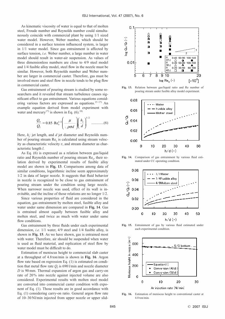
As Eq. (6) is expressed as a relation between gas/liquidratio and Reynolds number of pouring stream Res, their re-lation derived by experimental results of fusible alloymodel are shown in Fig. 13. Comparisons among data ofsimilar conditions, logarithmic incline seem approximately1/2 in data of larger nozzle. It suggests that fluid behaviorin nozzle is recognized to be close to gas entrainment ofpouring stream under the condition using large nozzle.When narrower nozzle was used, effect of its wall is in-evitable, and the incline of those relations are no longer 1/2.
Since various properties of fluid are considered in theequation, gas entrainment by molten steel, fusible alloy andwater under same dimension are compared in Fig. 14. Gasis entrained almost equally between fusible alloy andmolten steel, and twice as much with water under sameflow conditions.
Gas entrainment by three fluids under each experimentaldimension, i.e. 1/1 water, 4/9 steel and 1/4 fusible alloy, isshown in Fig. 15. As we have shown, gas is entrained mostwith water. Therefore, air should be suspended when wateris used as fluid material, and replication of steel flow bywater model must be difficult to do.
Estimation of meniscus height to commercial slab casterat a throughput of 4.8 ton/min is shown in Fig. 16. Argonflow rate based on regression Eq. (1) is estimated on condi-tion that metal flow rate Ql is 690 l/min and nozzle diameterD is 90 mm. Thermal expansion of argon gas and carry-onrate of 20% into nozzle against injected volume are alsoconsidered. Experimental results with molten steel modelare converted into commercial caster condition with expo-nent of Eq. (1). Those results are in good accordance withEq. (1) considering carry-on ratio. General argon flow rateof 10–30 Nl/min injected from upper nozzle or upper slid-
Q
Q d
h
da
ls
jRe�0 85 1 2
1 2
. /
/
⋅
µ
ρσ
ISIJ International, Vol. 47 (2007), No. 6
845 © 2007 ISIJ
Fig. 13. Relation between gas/liquid ratio and Re number ofpouring stream under fusible alloy model experiment.
Fig. 15. Entrainment of gas by various fluid estimated undereach experimental condition.
Fig. 16. Estimation of meniscus height to conventional caster at4.8 ton/min.
Fig. 14. Comparison of gas entrainment by various fluid esti-mated under CC operating condition.

ing plate at commercial slab caster makes steel flow in thenozzle plug-flow.
5. Conclusions
To find a solution for fluid flow in the submerged entrynozzle during conventional slab caster operation, fluidmodes with fusible alloy and molten steel was examined.Net argon flow rate through mold meniscus was also meas-ured. Results obtained by present work are summarized asfollows.
(1) In fusible alloy model experiment, both potentialflow and plug flow emerged depending on argon flow rate,metal flow rate and nozzle diameter. Decreasing of argonflow rate, increasing of metal flow rate and reducing of noz-zle diameter led to a rise of meniscus height in nozzle.
(2) Molten steel flow could be observed through trans-parent immersion nozzle. Both potential-flow and plug-flowalso emerged depending on argon flow rate.
(3) Nozzle internal pressure measured during flowingwas negative and coincides with estimated value to raise thefluid obtained by reverse calculation from measured menis-cus height.
(4) According to measurement of net argon flow ratethrough mold meniscus, about 20% of argon gas injectedfrom upper sliding plate is brought into nozzle at moltensteel system. Although gas bubble diameter and the buoy-ancy force on them must be different depending on fluidmaterial and flow condition, injected gas distribution in themold width direction seems similar among water, fusiblealloy and molten steel.
(5) Taking these experimental results into considera-tion, it is concluded that in conventional slab caster, sub-
merged entry nozzle must be filled with molten steel andsteel flow must be like a plug-flow during usual operation.
REFERENCES
1) K. Takatani: Tetsu-to-Hagané, 90 (2004), 751.2) E. Takeuchi, T. Toh, H. Harada, M. Zeze, H. Tanaka, M. Hojo, T.
Ishii and K. Shigematsu: Nippon Steel Tech. Rep., 351 (1993), 27.3) E. Takeuchi, H. Tanaka, K. Okobira, K. Wada and H. Kajioka:
CAMP-ISIJ, 4 (1991), 24.4) S. Yuhara, K. Nakai and K. Sorimachi: Proc. 3rd European Conf. on
Continuous Casting, Vol. 2, UNESID, Madrid, (1998), 989.5) J. Kubota, N. Kubo, M. Suzuki, T. Ishii, R. Nishimachi and N. Ara-
maki: Tetsu-to-Hagané, 86 (2000), 271.6) H. Yamane, Y. Ohtani, J. Fukuda, T. Kawase, J. Nakashima and A.
Kiyose: 80th Steelmaking Conf. Proc., ISS, Warrendale, PA, (1997),159.
7) Y. Tsukaguchi, T. Watanabe, S. Yokoya, S. Hara, K. Marukawa andK. Nonobe: CAMP-ISIJ, 15 (2002), 839.
8) O. Nomura, M. Takai, Y. Okawa and T. Horiuchi: Shinagawa Tech.Rep., 43 (2000), 15.
9) N. Bessho, R. Yoda, H. Yamasaki, T. Fujii, T. Nozaki and S. Taka-tori: ISIJ Int., 31 (1991), 40.
10) A. Imamura, A. Kusano and N. Moritama: Tetsu-to-Hagané, 78(1992), 439.
11) S. Asano, K. Ichikawa, N. Tsukamoto, E. Iida, A. Morita and J.Inoue: Refractories (Taikabutsu), 42 (1990), 149.
12) H. Bai and B. G. Thomas: 83rd Steelmaking Conf. Proc., ISS, War-rendale, PA, (2000), 183.
13) A. Yamagami, Y. Ogura, T. Kubo, K. Matsumura and K. Yoshioka:Tetsu-to-Hagané, 72 (1986), S1078.
14) K. Takatani, Y. Tanizawa, H. Mizukami and K. Nishimura: ISIJ Int.,41 (2001), 1252.
15) S. M. Göklü and K. W. Lange: Proc. 6th Process Technology Conf.,ISS, Warrendale, PA, (1986), 1135.
16) K. Iwata, T. Chou and M. Inoue: Tetsu-to-Hagané, 68 (1982), 1922.17) R. Shimizu and M. Shimada: Tetsu-to-Hagané, 45 (1959), 251.18) Handbook of Iron and Steel, 3rd ed. I, ed. by ISIJ, Maruzen, Tokyo,
(1981), 183.
ISIJ International, Vol. 47 (2007), No. 6
846© 2007 ISIJ