Flowcomputer for Corrected Liquid Volume - GPIgpi.net/downloads/manuals/Flomec F126 Display with...
52
Flowcomputer for Corrected Liquid Volume Owner’s Manual – Model F126-P Signal input flowmeter - type P: pulse, Namur and coil Signal input pressure - type IA: (0)4-20mA Signal input temperature - type TP: PT100 2- or 3 wire Signal output: 0/4-20mA / 0-10V ref. corrected flowrate Options: Intrinsically Safe, Modbus Communication
-
Upload
phamnguyet -
Category
Documents
-
view
221 -
download
0
Transcript of Flowcomputer for Corrected Liquid Volume - GPIgpi.net/downloads/manuals/Flomec F126 Display with...

Flowcomputer for Corrected Liquid Volume Owner’s Manual – Model F126-P
Signal input flowmeter - type P: pulse, Namur and coil
Signal input pressure - type IA: (0)4-20mA
Signal input temperature - type TP: PT100 2- or 3 wire
Signal output: 0/4-20mA / 0-10V ref. corrected flowrate
Options: Intrinsically Safe, Modbus Communication

GPI_F126PEN_EL_TP_v0501_07
Page 2
SAFETY INSTRUCTIONS Any responsibility is lapsed if the instructions and procedures as described in this
manual are not followed.
LIFE SUPPORT APPLICATIONS: The F126-P-EL is not designed for use in life support appliances, devices, or systems where malfunction of the product can reasonably be expected to result in a personal injury. Customers using or selling these products for use in such applications do so at their own risk and agree to fully indemnify the manufacturer and supplier for any damages resulting from such improper use or sale.
Electro static discharge does inflict irreparable damage to electronics! Before installing or opening the unit, the installer has to discharge himself by touching a well-grounded object.
This unit must be installed in accordance with the EMC guidelines (Electro Magnetic Compatibility).
Do connect a proper grounding to the aluminum casing as indicated if the F126-P-EL has been supplied with the 115-230V AC power-supply type PM. The green / yellow wire between the back-casing and removable terminal-block may never be removed.
Intrinsically Safe applications: follow the instructions as mentioned in Chapter 5 and consult “Fluidwell F1..-..-XI - Documentation for Intrinsic Safety”.
DISPOSAL At the end of its life this product should be disposed of according to local regulations
regarding waste electronic equipment. If a battery is present in this product it should be disposed of separately. The separate collection and recycling of your waste equipment will help to conserve natural resources and ensure that it is recycled in a manner that protects the environment.
SAFETY RULES AND PRECAUTIONARY MEASURES The manufacturer accepts no responsibility whatsoever if the following safety rules and
precautions instructions and the procedures as described in this manual are not followed. Modifications of the F126-P-EL implemented without preceding written consent from the
manufacturer, will result in the immediate termination of product liability and warranty period. Installation, use, maintenance and servicing of this equipment must be carried out by authorized
technicians. Check the mains voltage and information on the manufacturer's plate before installing the unit. Check all connections, settings and technical specifications of the various peripheral devices
with the F126-P-EL supplied. Open the casing only if all leads are free of potential. Never touch the electronic components (ESD sensitivity). Never expose the system to heavier conditions than allowed according to the casing
classification (see manufacture's plate and chapter 4.2.). If the operator detects errors or dangers, or disagrees with the safety precautions taken, then
inform the owner or principal responsible. The local labor and safety laws and regulations must be adhered to.

GPI_F126PEN_EL_TP_v0501_07
Page 3
ABOUT THE OPERATION MANUAL This operation manual is divided into two main sections: The daily use of the unit is described in chapter 2 "Operation". These instructions are meant for
users. The following chapters and appendices are exclusively meant for electricians/technicians. These
provide a detailed description of all software settings and hardware installation guidance. This operation manual describes the standard unit as well as most of the options available. For additional information, please contact your supplier. A hazardous situation may occur if the F126-P-EL is not used for the purpose it was designed for or is used incorrectly. Please carefully note the information in this operating manual indicated by the pictograms:
A "warning" indicates actions or procedures which, if not performed correctly, may lead to personal injury, a safety hazard or damage of the F126-P-EL or connected instruments. A "caution" indicates actions or procedures which, if not performed correctly, may lead to personal injury or incorrect functioning of the F126-P-EL or connected instruments. A "note" indicates actions or procedures which, if not performed correctly, may indirectly affect operation or may lead to an instrument response which is not planned.
Hardware version : 02.01.xx Software version : 02.05.xx Manual : GPI_F126PEN_EL_TP_v0501_07 © Copyright 2015 : Fluidwell bv - The Netherlands. Information in this manual is subject to change without prior notice. The manufacturer is not responsible for mistakes in this material or for incidental damage caused as a direct or indirect result of the delivery, performance or use of this material. © All rights reserved. No parts of this publication may be reproduced or used in any form or by any means without written permission of your supplier.
GPI_F126PEN_EL_TP_v0501_07
Page 4
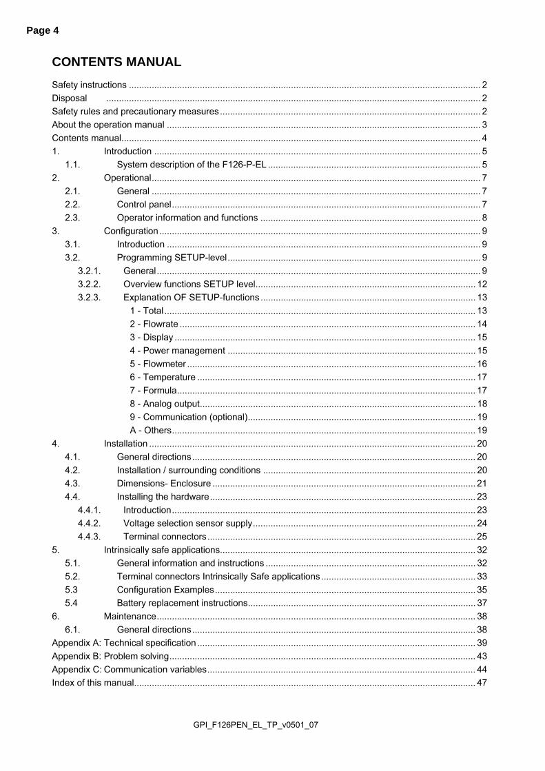
CONTENTS MANUAL Safety instructions ........................................................................................................................................... 2 Disposal .................................................................................................................................................... 2 Safety rules and precautionary measures ....................................................................................................... 2 About the operation manual ............................................................................................................................ 3 Contents manual .............................................................................................................................................. 4 1. Introduction ................................................................................................................................. 5
1.1. System description of the F126-P-EL .................................................................................... 5 2. Operational .................................................................................................................................. 7
2.1. General .................................................................................................................................. 7 2.2. Control panel .......................................................................................................................... 7 2.3. Operator information and functions ....................................................................................... 8
3. Configuration ............................................................................................................................... 9 3.1. Introduction ............................................................................................................................ 9 3.2. Programming SETUP-level .................................................................................................... 9
3.2.1. General ................................................................................................................................ 9 3.2.2. Overview functions SETUP level ....................................................................................... 12 3.2.3. Explanation OF SETUP-functions ..................................................................................... 13
1 - Total ........................................................................................................................... 13 2 - Flowrate ..................................................................................................................... 14 3 - Display ....................................................................................................................... 15 4 - Power management .................................................................................................. 15 5 - Flowmeter .................................................................................................................. 16 6 - Temperature .............................................................................................................. 17 7 - Formula ...................................................................................................................... 17 8 - Analog output ............................................................................................................. 18 9 - Communication (optional) .......................................................................................... 19 A - Others ........................................................................................................................ 19
4. Installation ................................................................................................................................. 20 4.1. General directions ................................................................................................................ 20 4.2. Installation / surrounding conditions .................................................................................... 20 4.3. Dimensions- Enclosure ........................................................................................................ 21 4.4. Installing the hardware ......................................................................................................... 23
4.4.1. Introduction ........................................................................................................................ 23 4.4.2. Voltage selection sensor supply ........................................................................................ 24 4.4.3. Terminal connectors .......................................................................................................... 25
5. Intrinsically safe applications..................................................................................................... 32 5.1. General information and instructions ................................................................................... 32 5.2. Terminal connectors Intrinsically Safe applications ............................................................. 33 5.3 Configuration Examples ....................................................................................................... 35 5.4 Battery replacement instructions .......................................................................................... 37
6. Maintenance .............................................................................................................................. 38 6.1. General directions ................................................................................................................ 38
Appendix A: Technical specification .............................................................................................................. 39 Appendix B: Problem solving ......................................................................................................................... 43 Appendix C: Communication variables .......................................................................................................... 44 Index of this manual ....................................................................................................................................... 47

GPI_F126PEN_EL_TP_v0501_07
Page 5
1. INTRODUCTION 1.1. SYSTEM DESCRIPTION OF THE F126-P-EL Functions and features The flowcomputer Model F126-P-EL is a microprocessor driven instrument for the calculation of standard volumetric flow or mass flow for liquid applications using flow equations. This product has been designed with a focus on: ultra-low power consumption to allow long-life battery powered applications (type PB / PC), intrinsic safety for use in hazardous applications (type XI), several mounting possibilities with aluminum or GRP enclosures for harsh industrial
surroundings, ability to process all types of flowmeter signals, transmitting possibilities with analog and communication (option) outputs. Flowmeter and temperature input This manual describes the unit with a pulse type input from the flowmeter "-P version". Other versions are available to process (0)4-20mA or 0-10V flowmeter signals. One flowmeter with a passive or active pulse, Namur or sine wave (coil) signal output can be connected to the F126-P-EL. To power the sensor, several options are available. This unit has a PT100 temperature input “-TP version ”. Other versions are available to process 0-10V or (0)4-20mA temperature signals. Standard output Configurable linear (0)4-20mA or 0-10V analog output with 10-bits resolution mirroring the actual
flowrate at standard conditions. Flowrate levels as well as the minimum and maximum signal output can be tuned.
Fig. 1: Typical application for the F126-P-EL.

GPI_F126PEN_EL_TP_v0501_07
Page 6
Configuration of the unit The F126-P-EL was designed to be implemented in many types of applications. For that reason, a SETUP-level is available to configure your F126-P-EL according to your specific requirements. SETUP includes several important features, such as K-factors, Span, measurement units, signal selection etc. All setting are stored in EEPROM memory and will not be lost in the event of power failure or a drained battery. To extend the battery-life time (option), please make use of the power-management functions as described in chapter 3.2.3. Display information The unit has a large transflective LCD with all kinds of symbols and digits to display measuring units, status information, trend-indication and key-word messages. Flowrate and totals can be displayed either with the small 8mm digits or with the 17mm digits. A backup of the total and accumulated total in EEPROM memory is made every minute. Options The following options are available: isolated or active 4-20mA / 0-10V / 0-20mA analog output, full Modbus communication RS232/485 (also battery powered), intrinsic safety, power- and sensor-supply options, panel-mount, wall-mount and weather-proof enclosures, flame proof enclosure.

GPI_F126PEN_EL_TP_v0501_07
Page 7
2. OPERATIONAL 2.1. GENERAL The F126-P-EL may only be operated by personnel who are authorized and trained by
the operator of the facility. All instructions in this manual are to be observed. Take careful notice of the " Safety rules, instructions and precautionary measures " in
the front of this manual. This chapter describes the daily use of the F126-P-EL. This instruction is meant for users / operators. 2.2. CONTROL PANEL The following keys are available:
Fig. 2: Control Panel.
Functions of the keys
This key is used to program and save new values or settings. It is also used to gain access to SETUP-level; please read chapter 3.
This key is used to SELECT accumulated total. The arrow-key is used to increase a value after PROG has been pressed or to configure the unit; please read chapter 3.
Press this key twice to CLEAR the value for total. The arrow-key is used to select a digit after PROG has been pressed or to configure the unit; please read chapter 3.

GPI_F126PEN_EL_TP_v0501_07
Page 8
2.3. OPERATOR INFORMATION AND FUNCTIONS In general, the F126-P-EL will always function at Operator level. The information displayed is dependant upon the SETUP-settings. All pulses generated by the connected flowmeter are measured by the F126-P-EL in the background, whichever screen refresh rate setting is chosen. After pressing a key, the display will be updated very quickly during a 30 second period, after which it will slow-down again.
Fig. 3: Example of display information during process. For the Operator, the following functions are available: Display calculated flowrate and calculated total or calculated flowrate
This is the main display information of the F126-P-EL. After selecting any other information, it will always return to this main display automatically. Total is displayed on the upper-line of the display and flowrate on the bottom line. It is possible to display flowrate only with the large 17mm digits; in this instance press the SELECT-key to read the total. When "-------" is shown, then the flowrate value is too high to be displayed. The arrows indicate the increase/decrease of the flowrate trend.
Clear total
The value for total can be re-initialized. To do so, press CLEAR twice. After pressing CLEAR once, the flashing text "PUSH CLEAR" is displayed. To avoid re-initialization at this stage, press another key than CLEAR or wait for 20 seconds. Re-initialization of total DOES NOT influence the accumulated total.
Display calculated accumulated total
When the SELECT-key is pressed, total and accumulated total are displayed. The accumulated total cannot be re-initialized. The value will count up to 99,999,999,999. The unit and number of decimals are displayed according to the configuration settings for total.
Display line temperature
After pressing SELECT, the actual temperature is displayed. Low-battery alarm
When the battery voltage drops, it must be replaced. At first "low-battery" will flash, but as soon as it is displayed continuously, the battery MUST be replaced shortly after! Only original batteries supplied by the manufacturer may be used, else the guarantee and liability will be terminated. The remaining lifetime after the first moment of indication is generally several days up to some weeks.
Fig. 4: Example of low-battery alarm.
Alarm When "alarm" is displayed, please consult Appendix B: problem solving.
RUN
LOW BATTERY RUN

GPI_F126PEN_EL_TP_v0501_07
Page 9
3. CONFIGURATION 3.1. INTRODUCTION This and the following chapters are exclusively meant for electricians and non-operators. In these, an extensive description of all software settings and hardware connections are provided. Mounting, electrical installation, start-up and maintenance of the instrument may only
be carried out by trained personnel authorized by the operator of the facility. Personnel must read and understand this Operating Manual before carrying out its instructions.
The F126-P-EL may only be operated by personnel who are authorized and trained by the operator of the facility. All instructions in this manual are to be observed.
Ensure that the measuring system is correctly wired up according to the wiring diagrams. The housing may only be opened by trained personnel.
Take careful notice of the " Safety rules, instructions and precautionary measures " in the front of this manual.
3.2. PROGRAMMING SETUP-LEVEL 3.2.1. GENERAL Configuration of the F126-P-EL is done at SETUP-level. SETUP-level is reached by pressing the PROG/ENTER key for 7 seconds; at which time, both arrows will be displayed. In order to return to the operator level, PROG will have to be pressed for three seconds. Alternatively, if no keys are pressed for 2 minutes, the unit will exit SETUP automatically. SETUP can be reached at all times while the F126-P-EL remains fully operational. Note: A pass code may be required to enter SETUP. Without this pass code access to SETUP is denied. To enter SETUP-level:

GPI_F126PEN_EL_TP_v0501_07
Page 10
Matrix structure SETUP-level:
SCROLLING THROUGH SETUP-LEVEL Selection of function-group and function: SETUP is divided into several function groups and functions.
Each function has a unique number, which is displayed below the word "SETUP" at the bottom of the display. The number is a combination of two figures. The first figure indicates the function-group and the second figure the sub-function. Additionally, each function is expressed with a keyword. After selecting a sub-function, the next main function is selected by scrolling through all "active" sub-functions (e.g. 1, 11, 12, 13, 14, 1, 2, 3, 31 etc.).

GPI_F126PEN_EL_TP_v0501_07
Page 11
To change or select a value:
To change a value, use to select the digits and to increase that value. To select a setting, both and can be used. If the new value is invalid, the increase sign or decrease-sign will be displayed while you are programming. When data is altered but ENTER is not pressed, then the alteration can still be cancelled by waiting for 20 seconds or by pressing ENTER for three seconds: the PROG-procedure will be left automatically and the former value reinstated. Note: alterations will only be set after ENTER has been pressed! To return to OPERATOR-level:
In order to return to the operator level, PROG will have to be pressed for three seconds. Also, when no keys are pressed for 2 minutes, SETUP will be left automatically.

GPI_F126PEN_EL_TP_v0501_07
Page 12
3.2.2. OVERVIEW FUNCTIONS SETUP LEVEL
SETUP FUNCTIONS AND VARIABLES 1 TOTAL 11 UNIT L - m3 - kg - lb - GAL - USGAL - bbl - no unit 12 DECIMALS 0 - 1 - 2 - 3 (Ref: displayed value) 13 K-FACTOR: 0.000010 - 9,999,999 14 DECIMALS K-FACTOR 0 - 6 2 FLOWRATE 21 UNIT mL, L, m3, mg, g, kg, ton, GAL, bbl, lb, cf, rev, no unit 22 TIME UNIT sec - min - hour - day 23 DECIMALS 0 - 1 - 2 - 3 (Ref: displayed value) 24 K-FACTOR 0.000010 - 9,999,999 25 DECIMALS K-FACTOR 0 - 6 26 PERIOD TIME 0.1 - 999.9 seconds 27 FILTER 0 - 99 3 DISPLAY 31 FUNCTION total - flowrate 4 POWER MAN 41 LCD UPDATE fast - 1 sec - 3 sec - 15 sec - 30 sec - off 42 BATTERY MODE operational - shelf 5 FLOWMETER 51 SIGNAL npn - npn_lp - reed - reed_lp - pnp - pnp_lp - namur -
coil_hi - coil_lo - act_8.1 - act_12 - act_24 6 TEMPERATURE - A/B 61 NO. OF WIRES 2 - 3 62 FILTER 10 - 99 63 DISPLAY °C - °F - K 7 FORMULA 71 EQUATIONS TYPE EL - (fixed) 72 THERMAL EXPANSION
COEFFICIENT 0.000000 - 9.999999
73 NORMAL TEMPERATURE
0.00 - 99,999.99 K
8 ANALOG 81 OUTPUT disable - enable 82 4mA / 0V 0000.000 - 9,999,999 83 20mA / 10V 0000.000 - 9,999,999 84 CUT-OFF 0.0 - 9.9% 85 TUNE MIN - 4mA / 0V 0 - 9,999 86 TUNE MAX- 20mA / 10V 0 - 9,999 87 FILTER 00 - 99 9 COMMUNIC 91 SPEED / BAUDRATE 1200 - 2400 - 4800 - 9600 92 ADDRESS 1 - 255 93 MODE RTU - off A OTHERS A1 TYPE / MODEL A2 SOFTWARE VERSION A3 SERIAL NO. A4 PASSWORD 0000 - 9999 A5 TAGNUMBER 0000000 - 9999999

GPI_F126PEN_EL_TP_v0501_07
Page 13
3.2.3. EXPLANATION OF SETUP-FUNCTIONS
1 - TOTAL MEASUREMENT UNIT 11
SETUP - 11 determines the measurement unit for total, accumulated total and pulse output. The following units can be selected: L - m3 - kg - lb. - GAL - USGAL - bbl - _ (no unit). Alteration of the measurement unit will have consequences for operator and SETUP-level values. Please note that the K-factor has to be adapted as well; the calculation is not done automatically.
DECIMALS 12
The decimal point determines for total, accumulated total and pulse output the number of digits following the decimal point. The following can be selected:
0000000 - 111111.1 - 22222.22 - 3333.333
K-FACTOR 13
With the K-factor, the flowmeter pulse signals are converted to a quantity. The K-factor is based on the number of pulses generated by the flowmeter per selected measurement unit (SETUP 11), for example per cubic meter. The more accurate the K-factor, the more accurate the functioning of the system will be. Example 1: Calculating the K-factor.
Let us assume that the flowmeter generates 2.4813 pulses per liter and the selected unit is "cubic meters / m3". A cubic meter consists of 1000 parts of one liter which implies 2,481.3 pulses per m3. So, the K-factor is 2,481.3. Enter for SETUP - 13: "2481300" and for SETUP - 14 - decimals K-factor "3".
Example 2: Calculating the K-factor.
Let us assume that the flowmeter generates 6.5231 pulses per gallon and the selected measurement unit is gallons. So, the K-Factor is 6.5231. Enter for SETUP - 13: "6523100" and for SETUP - 14 decimals K-factor "6".
DECIMALS K-FACTOR 14
This setting determines the number of decimals for the K-factor entered. (SETUP 13). The following can be selected: 0 - 1 - 2 - 3 - 4 - 5 - 6 Please note that this setting influences the accuracy of the K-factor indirectly. (i.e. the position of the decimal point and thus the value given) This setting has NO influence on the displayed number of digits for total (SETUP 12)!

GPI_F126PEN_EL_TP_v0501_07
Page 14
2 - FLOWRATE The settings for total and flowrate are entirely separate. In this way, different units of measurement can be used for each e.g. cubic meters for total and liters for flowrate. The display update time for flowrate is one second or more. Note: these settings also influence the analog output. MEASUREMENT UNIT 21
SETUP - 21 determines the measurement unit for flowrate. The following units can be selected: mL - L - m3 - mg - g - kg - ton - GAL - bbl - lb - cf - REV - no unit - scf - Nm3 - NL - P. Alteration of the measurement unit will have consequences for operator and SETUP-level values. Please note that the K-factor has to be adapted as well; the calculation is not done automatically.
TIME UNIT 22
The flowrate can be calculated per second (SEC), minute (MIN), hour (HR) or day (DAY).
DECIMALS 23
This setting determines for flowrate the number of digits following the decimal point. The following can be selected: 00000 - 1111.1 - 2222.22 - 3333.333
K-FACTOR 24
With the K-factor, the flowmeter pulse signals are converted to a flowrate. The K-factor is based on the number of pulses generated by the flowmeter per selected measurement unit (SETUP 21), for example per liter. The more accurate the K-factor, the more accurate the functioning of the system will be. For examples read SETUP 13.
DECIMALS K-FACTOR 25
This setting determines the number of decimals for the K-factor (SETUP 24). The following can be selected: 0 - 1 - 2 - 3 - 4 - 5 - 6 Please note that this SETUP - influences the accuracy of the K-factor indirectly. This setting has NO influence on the displayed number of digits for "flowrate" (SETUP 23)!
PERIOD 26
The flowrate is calculated by counting the number of pulses within a certain time, for example 1 second. The longer the time the more accurate the flowrate will be. The maximum value is 999.9 seconds. Note: this setting does influence the update time for the analog output directly (maximum update 10 times a second). If the output response is too slow, decrease the number of pulses. Note: the shorter the time, the higher the power consumption of the unit will be (important for battery powered applications).
FILTER 27
This function is used to stabilize the flowrate reading. With the help of this digital filter a more stable but less actual reading can be obtained. The filter principal is based on three input values: the filter level (01-99), the last calculated flowrate on both the A / B flow and the last average value. The higher the filter level, the longer the response time on a value change will be. Below, several filter levels with there response times are indicated:
FILTER VALUE RESPONSE TIME ON STEP CHANGE OF ANALOG VALUE. TIME IN SECONDS
50% INFLUENCE 75% INFLUENCE 90% INFLUENCE 99% INFLUENCE 01 filter disabled filter disabled filter disabled filter disabled 02 0.1 second 0.2 second 0.4 second 0.7 second 03 0.2 second 0.4 second 0.6 second 1.2 seconds 05 0.4 second 0.7 second 1.1 seconds 2.1 seconds
Continued next page >>>

GPI_F126PEN_EL_TP_v0501_07
Page 15
2 - FLOWRATE (CONTINUED) FILTER VALUE RESPONSE TIME ON STEP CHANGE OF ANALOG VALUE.
TIME IN SECONDS 50% INFLUENCE 75% INFLUENCE 90% INFLUENCE 99% INFLUENCE
10 0.7 second 1.4 seconds 2.2 seconds 4.4 seconds 20 1.4 seconds 2.8 seconds 4.5 seconds 9.0 seconds 30 2.1 seconds 4 seconds 7 seconds 14 seconds 50 3.5 seconds 7 seconds 11 seconds 23 seconds 75 5.2 seconds 10 seconds 17 seconds 34 seconds 99 6.9 seconds 14 seconds 23 seconds 45 seconds
3 - DISPLAY FUNCTION 31
The large 17mm digits can be set to display total or flowrate. When "total" is selected, both total and flowrate are displayed simultaneously. When "flowrate" is selected, only flowrate will be displayed with it’s measuring unit while total will be displayed after pressing SELECT.
4 - POWER MANAGEMENT When used with the internal battery option, the user can expect reliable measurement over a long period of time. The F126-P-EL has several smart power management functions to extend the battery life time significantly. Two of these functions can be set: LCD NEW 41
The calculation of the display-information influences the power consumption significantly. When the application does not require a fast display update, it is strongly advised to select a slow refresh rate. Please understand that NO information will be lost; every pulse will be counted and the output signals will be generated in the normal way. The following can be selected: Fast - 1 sec - 3 sec - 15 sec - 30 sec - off. Example 3: Battery life-time
battery life-time with a coil pick-up, 1KHz. pulses and FAST update: about 2 years. battery life-time with a coil pick-up, 1KHz. pulses and 1 sec update: about 5 years.
Note: after a button has been pressed by the operator - the display refresh rate will always switch to FAST for 30 seconds. When "OFF" is selected, the display will be switched off after 30 seconds and will be switched on as soon as a button has been pressed.
BATTERY-MODE 42
The unit has two modes: operational or shelf. After "shelf" has been selected, the unit can be stored for several years; it will not count pulses, the display is switched off but all settings and totals are stored. In this mode, power consumption is extremely low. To wake up the unit again, press the SELECT-key twice.

GPI_F126PEN_EL_TP_v0501_07
Page 16
5 - FLOWMETER SIGNAL 51
The F126-P-EL is able to handle several types of input signal. The type of flowmeter pickup / signal is selected with function. Note: The selections "active pulse" offer a detection level of 50% of the supply voltage. Read also par. 4.4.3. Flowmeter input terminal 09-11.
TYPE OF SIGNAL EXPLANATION RESISTANCE FREQ. / MV REMARK
NPN NPN input 100K
pull-up 6 kHz. (open collector)
NPN - LP NPN input
with low pass filter 100K
pull-up 2.2 kHz.
(open collector) less sensitive
REED Reed-switch input 1M
pull-up 1.2 kHz.
REED - LP Reed-switch input with low pass filter
1M pull-up
120 Hz. Less sensitive
PNP PNP input 100K
pull-down 6 kHz.
PNP - LP PNP input
with low pass filter 100K
pull-down 700 Hz. Less sensitive
NAMUR Namur input 820 Ohm pull-down
4 kHz. External power
required
COIL HI High sensitive coil input - 20mV p.t.p.
Sensitive for disturbance!
COIL LO Low sensitive coil input - 90mV p.t.p.
Normal sensitivity
ACT_8.1 Active pulse input
8.1 V DC 3K9 10KHz.
External power required
ACT_12 Active pulse input
12 V DC 4K 10KHz.
External power required
ACT_24 Active pulse input
24 V DC 3K 10KHz.
External power required

GPI_F126PEN_EL_TP_v0501_07
Page 17
6 - TEMPERATURE NO. OF WIRES 61
Do select here the number of wires of the two PT100 elements - two or three.
FILTER 62
The analog output signal of a sensor does mirror the actual temperature. This signal is measured several times a second. The value measured is a "snap-shot" of the real temperature as it will be fluctuating. With the help of this digital filter a stable and accurate reading can be obtained while the filter level can be set to a desired value. The filter principal is based on three input values: the filter level (01-99), the last measured analog value and the last average value. The higher the filter level, the longer the response time on a value change will be.
FILTER VALUE RESPONSE TIME ON STEP CHANGE OF ANALOG VALUE. TIME IN SECONDS
50% INFLUENCE 75% INFLUENCE 90% INFLUENCE 99% INFLUENCE 10 1.8 seconds 3.5 seconds 5.6 seconds 11 seconds 20 3.5 seconds 7.0 seconds 11 seconds 23 seconds 30 5.3 seconds 10 seconds 17 seconds 34 seconds 50 8.8 seconds 17 seconds 29 seconds 57 seconds 75 13 seconds 26 seconds 43 seconds 86 seconds 99 17 seconds 34 seconds 57 seconds 114 seconds
DISPLAY UNIT 63
SETUP - 63 determines the displayed unit for the Operator The following units can be selected: °C - °F - K
7 - FORMULA EQUATIONS TYPE 71
This function describes the supplied equations. The supplied Model is the F126-P-EL. “EL” stands for Equations Liquid - flowcomputer for corrected liquid volume. The formula used: Qnormal = Q * (1 + α (Tnormal - T)) where Qnormal = calculated volume at reference conditions Q = measured volume α = thermal expansion coefficient Tnormal = reference temperature T = measured temperature
THERMAL EXPANSION COEFFICIENT 72
Enter here the thermal expansion coefficient α for the liquid used. The value to be entered has to be multiplied with 1000. The decimal position is fixed but can not be displayed: x,xxxxxx With the default value of 0.000000 the volume correction is disabled. Examples: Calculation of the thermal expansion coefficient α for water is 0,00031 per K. Enter: 0310000. α for petrol is 0,00110 per K. Enter: 1100000.
NORMAL TEMPERATURE 73
Enter here the reference temperature Tnormal in degrees Kelvin (K). In most applications, the volume has to be calculated at 15°C which is 288,15 K.
GPI_F126PEN_EL_TP_v0501_07
Page 18
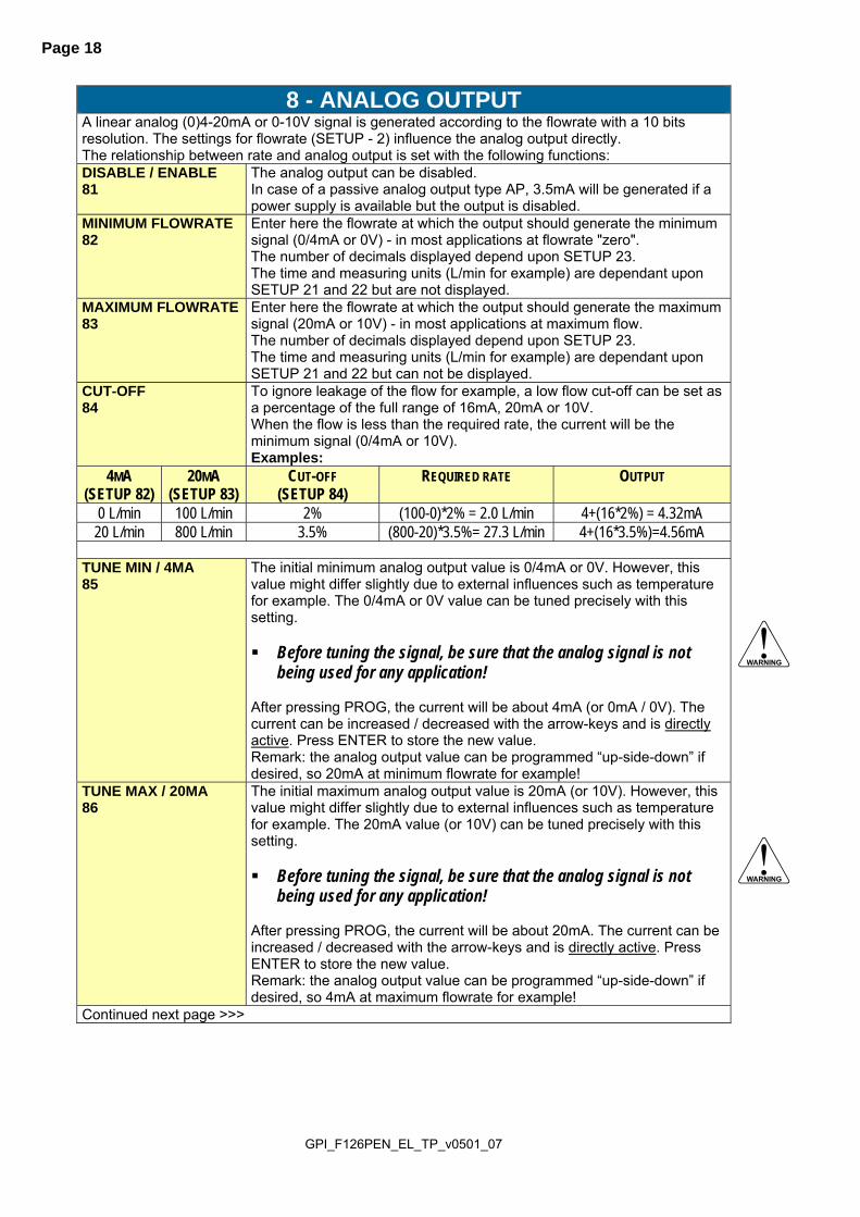
8 - ANALOG OUTPUT A linear analog (0)4-20mA or 0-10V signal is generated according to the flowrate with a 10 bits resolution. The settings for flowrate (SETUP - 2) influence the analog output directly. The relationship between rate and analog output is set with the following functions: DISABLE / ENABLE 81
The analog output can be disabled. In case of a passive analog output type AP, 3.5mA will be generated if a power supply is available but the output is disabled.
MINIMUM FLOWRATE 82
Enter here the flowrate at which the output should generate the minimum signal (0/4mA or 0V) - in most applications at flowrate "zero". The number of decimals displayed depend upon SETUP 23. The time and measuring units (L/min for example) are dependant upon SETUP 21 and 22 but are not displayed.
MAXIMUM FLOWRATE 83
Enter here the flowrate at which the output should generate the maximum signal (20mA or 10V) - in most applications at maximum flow. The number of decimals displayed depend upon SETUP 23. The time and measuring units (L/min for example) are dependant upon SETUP 21 and 22 but can not be displayed.
CUT-OFF 84
To ignore leakage of the flow for example, a low flow cut-off can be set as a percentage of the full range of 16mA, 20mA or 10V. When the flow is less than the required rate, the current will be the minimum signal (0/4mA or 10V). Examples:
4MA (SETUP 82)
20MA (SETUP 83)
CUT-OFF (SETUP 84)
REQUIRED RATE OUTPUT
0 L/min 100 L/min 2% (100-0)*2% = 2.0 L/min 4+(16*2%) = 4.32mA 20 L/min 800 L/min 3.5% (800-20)*3.5%= 27.3 L/min 4+(16*3.5%)=4.56mA
TUNE MIN / 4MA 85
The initial minimum analog output value is 0/4mA or 0V. However, this value might differ slightly due to external influences such as temperature for example. The 0/4mA or 0V value can be tuned precisely with this setting. Before tuning the signal, be sure that the analog signal is not
being used for any application! After pressing PROG, the current will be about 4mA (or 0mA / 0V). The current can be increased / decreased with the arrow-keys and is directly active. Press ENTER to store the new value. Remark: the analog output value can be programmed “up-side-down” if desired, so 20mA at minimum flowrate for example!
TUNE MAX / 20MA 86
The initial maximum analog output value is 20mA (or 10V). However, this value might differ slightly due to external influences such as temperature for example. The 20mA value (or 10V) can be tuned precisely with this setting. Before tuning the signal, be sure that the analog signal is not
being used for any application! After pressing PROG, the current will be about 20mA. The current can be increased / decreased with the arrow-keys and is directly active. Press ENTER to store the new value. Remark: the analog output value can be programmed “up-side-down” if desired, so 4mA at maximum flowrate for example!
Continued next page >>>

GPI_F126PEN_EL_TP_v0501_07
Page 19
8 - ANALOG OUTPUT (CONTINUED) FILTER 87
This function is used to stabilize the analog output signal. The output value is updated every 0.1 second. With the help of this digital filter a more stable but less precise reading can be obtained. The filter principal is based on three input values: the filter level (01-99), the last analog output value and the last average value. The higher the filter level, the longer the response time on a value change will be. Below, several filter levels with their response times are indicated:
FILTER VALUE RESPONSE TIME ON STEP CHANGE OF ANALOG VALUE. TIME IN SECONDS
50% INFLUENCE 75% INFLUENCE 90% INFLUENCE 99% INFLUENCE 01 filter disabled filter disabled filter disabled filter disabled 02 0.1 second 0.2 second 0.4 second 0.7 second 03 0.2 second 0.4 second 0.6 second 1.2 seconds 05 0.4 second 0.7 second 1.1 seconds 2.1 seconds 10 0.7 second 1.4 seconds 2.2 seconds 4.4 seconds 20 1.4 seconds 2.8 seconds 4.5 seconds 9.0 seconds 30 2.1 seconds 4 seconds 7 seconds 14 seconds 50 3.5 seconds 7 seconds 11 seconds 23 seconds 75 5.2 seconds 10 seconds 17 seconds 34 seconds 99 6.9 seconds 14 seconds 23 seconds 45 seconds
9 - COMMUNICATION (OPTIONAL) The functions described below deal with hardware that is not part of the standard delivery. Programming of these functions does not have any effect if this hardware has not been installed. Consult Appendix C and the Modbus communication protocol description for a detailed explanation. BAUDRATE 91
For external control, the following communication speeds can be selected: 1200 - 2400 - 4800 - 9600 baud
BUS ADDRESS 92
For communication purposes, a unique identity can be attributed to every F126-P-EL. This address can vary from 1-255.
MODE 93
The communication protocol is Modbus RTU mode. Select OFF, to disable this communication function.
A - OTHERS TYPE OF MODEL A1
For support and maintenance it is important to have information about the characteristics of the F126-P-EL. Your supplier will ask for this information in the case of a serious breakdown or to assess the suitability of your model for upgrade considerations.
VERSION SOFTWARE A2
For support and maintenance it is important to have information about the characteristics of the F126-P-EL. Your supplier will ask for this information in the case of a serious breakdown or to assess the suitability of your model for upgrade considerations.
SERIAL NUMBER A3
For support and maintenance it is important to have information about the characteristics of the F126-P-EL. Your supplier will ask for this information in the case of a serious breakdown or to assess the suitability of your model for upgrade considerations.
PASSWORD A4
All SETUP-values can be password protected. This protection is disabled with value 0000 (zero). Up to and including 4 digits can be programmed, for example 1234.
TAGNUMBER A5
For identification of the unit and communication purposes, a unique tag number of maximum 7 digits can be entered.

GPI_F126PEN_EL_TP_v0501_07
Page 20
4. INSTALLATION 4.1. GENERAL DIRECTIONS Mounting, electrical installation, start-up and maintenance of this instrument may only be carried
out by trained personnel authorized by the operator of the facility. Personnel must read and understand this Operating Manual before carrying out its instructions.
The F126-P-EL may only be operated by personnel who are authorized and trained by the operator of the facility. All instructions in this manual are to be observed.
Ensure that the measuring system is correctly wired up according to the wiring diagrams. Protection against accidental contact is no longer assured when the housing cover is removed or the panel cabinet has been opened (danger from electrical shock). The housing may only be opened by trained personnel.
Take careful notice of the " Safety rules, instructions and precautionary measures " at the front of this manual.
4.2. INSTALLATION / SURROUNDING CONDITIONS
Take the relevant IP classification of the casing into account (see manufactures plate). Even an IP67 (NEMA 4X) casing should NEVER be exposed to strongly varying (weather) conditions. When panel-mounted, the unit is IP65 (NEMA 4X)! When used in very cold surroundings or varying climatic conditions, take the necessary precautions against moisture by placing a dry sachet of silica gel, for example, inside the instrument case.
Mount the F126-P-EL on a solid structure to avoid vibrations.
GPI_F126PEN_EL_TP_v0501_07
Page 21
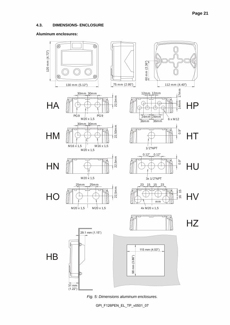
4.3. DIMENSIONS- ENCLOSURE Aluminum enclosures:
75 mm (2.95")130 mm (5.12") 112 mm (4.40")
60 m
m (2
.36"
)
120
mm
(4.7
2")
M20 x 1,5PG9 PG9
30mm 30mm
22,5
mm
M20 x 1,5M16 x 1,5 M16 x 1,5
30mm 30mm
22,5
0mm
M20 x 1,5
22,5
mm
M20 x 1,5 M20 x 1,5
25mm 25mm
22,5
mm
1/2"NPT
0.9"
3x 1/2"NPT
0.12" 0.12"
0.9"
HA
HM
HN
HO
HP
HT
HU
6 x M12
12mm 12mm
24mm24mm36mm36mm
14m
m17
mm
115 mm (4.53”)
98
mm
(3.
86”)HB
29.1 mm (1.15”)
31 mm (1.22”)
HZ
4x M20 x 1,5
15 1515
HV
232316
mm
Fig. 5: Dimensions aluminum enclosures.

GPI_F126PEN_EL_TP_v0501_07
Page 22
GRP enclosures:
75 mm (2.95")130 mm (5.12") 112 mm (4.40")
60 m
m (2
.36"
)
120
mm
(4.7
2")
HDHK
HK back box:(flat bottom)
HE
HF
HG
HHD=12mm
12mm 12mm
24mm24mm36mm36mm
14m
m17
mm
22,5
mm
30mm 30mm
D=16mmD=20mm
0.9"
D=22mm (0.866")
22,5
mm
25mm 25mm
D=20mm D=20mm
D=16mm
HC
75 mm (2.95") 118 mm (4.65”)
104
mm
(4.0
9”)
HJ0.9”
0.12” 0.12”
3x D=22mm (0.866”)
115 mm (4.53”)
98 m
m (
3.86
”)
29.1 mm (1.15”)
31 mm (1.22”)
Fig. 6: Dimensions GRP enclosures.

GPI_F126PEN_EL_TP_v0501_07
Page 23
4.4. INSTALLING THE HARDWARE 4.4.1. INTRODUCTION Electro static discharge does inflict irreparable damage to electronics! Before installing or
opening the unit, the installer has to discharge himself by touching a well-grounded object.
This unit must be installed in accordance with the EMC guidelines (Electro Magnetic Compatibility).
Aluminum enclosures When installed in an aluminum enclosure and a potentially explosive atmosphere requiring
apparatus of equipment protection level Ga and Da, the unit must be installed such that, even in the event of rare incidents, an ignition source due to impact or friction sparks between the enclosure and iron/steel is excluded.
Do ground the aluminum enclosure properly as indicated, if the F126-P-EL has been supplied with the 115-230V AC power-supply type PM. The green / yellow wire between the back-casing and removable terminal-block may never be removed.
Fig. 7: Grounding aluminum enclosure with type PM 115-230V AC. FOR INSTALLATION, PAY EMPHATIC ATTENTION TO: Separate cable glands with effective IP67 (NEMA4X) seals for all wires. Unused cable entries: ensure that you fit IP67 (NEMA4X) plugs to maintain rating. A reliable ground connection for both the sensor, and if applicable, for the metal casing. An effective screened cable for the input signal, and grounding of its screen to terminal 9 (GND)
or at the sensor itself, whichever is appropriate to the application.
GPI_F126PEN_EL_TP_v0501_07
Page 24
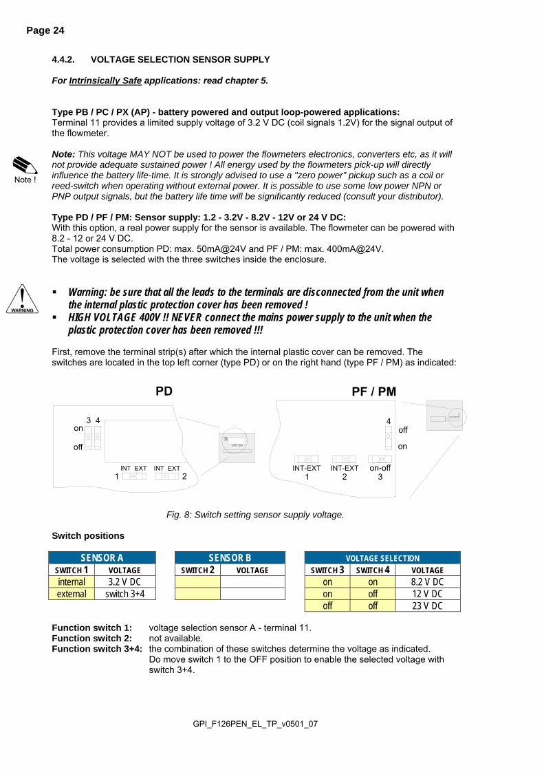
4.4.2. VOLTAGE SELECTION SENSOR SUPPLY For Intrinsically Safe applications: read chapter 5. Type PB / PC / PX (AP) - battery powered and output loop-powered applications: Terminal 11 provides a limited supply voltage of 3.2 V DC (coil signals 1.2V) for the signal output of the flowmeter. Note: This voltage MAY NOT be used to power the flowmeters electronics, converters etc, as it will not provide adequate sustained power ! All energy used by the flowmeters pick-up will directly influence the battery life-time. It is strongly advised to use a "zero power" pickup such as a coil or reed-switch when operating without external power. It is possible to use some low power NPN or PNP output signals, but the battery life time will be significantly reduced (consult your distributor). Type PD / PF / PM: Sensor supply: 1.2 - 3.2V - 8.2V - 12V or 24 V DC: With this option, a real power supply for the sensor is available. The flowmeter can be powered with 8.2 - 12 or 24 V DC. Total power consumption PD: max. 50mA@24V and PF / PM: max. 400mA@24V. The voltage is selected with the three switches inside the enclosure. Warning: be sure that all the leads to the terminals are disconnected from the unit when
the internal plastic protection cover has been removed ! HIGH VOLTAGE 400V !! NEVER connect the mains power supply to the unit when the
plastic protection cover has been removed !!! First, remove the terminal strip(s) after which the internal plastic cover can be removed. The switches are located in the top left corner (type PD) or on the right hand (type PF / PM) as indicated:
Fig. 8: Switch setting sensor supply voltage.
Switch positions
SENSOR A SENSOR B VOLTAGE SELECTION SWITCH 1 VOLTAGE SWITCH 2 VOLTAGE SWITCH 3 SWITCH 4 VOLTAGE internal 3.2 V DC on on 8.2 V DC external switch 3+4 on off 12 V DC
off off 23 V DC Function switch 1: voltage selection sensor A - terminal 11. Function switch 2: not available. Function switch 3+4: the combination of these switches determine the voltage as indicated.
Do move switch 1 to the OFF position to enable the selected voltage with switch 3+4.
GPI_F126PEN_EL_TP_v0501_07
Page 25
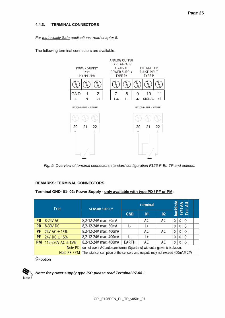
4.4.3. TERMINAL CONNECTORS For Intrinsically Safe applications: read chapter 5. The following terminal connectors are available:
Fig. 9: Overview of terminal connectors standard configuration F126-P-EL-TP and options.
REMARKS: TERMINAL CONNECTORS: Terminal GND- 01- 02: Power Supply - only available with type PD / PF or PM:
TYPE SENSOR SUPPLY Terminal
back
light
TYPE
AA
TY
PEA
U
GND 01 02
PD 8-24V AC 8,2-12-24V max. 50mA AC AC ◊ ◊ ◊ PD 8-30V DC 8,2-12-24V max. 50mA L- L+ ◊ ◊ ◊ PF 24V AC ± 15% 8,2-12-24V max. 400mA AC AC ◊ ◊ ◊ PF 24V DC ± 15% 8,2-12-24V max. 400mA L- L+ ◊ ◊ ◊ PM 115-230V AC ± 15% 8,2-12-24V max. 400mA EARTH AC AC ◊ ◊ ◊
Note PD do not use a AC autotransformer (Spartrafo) without a galvanic isolation. Note PF / PM The total consumption of the sensors and outputs may not exceed 400mA@24V
◊=option Note: for power supply type PX: please read Terminal 07-08 !
GND 1N L1
2
POWER SUPPLYTYPE
PD / PF / PM
7 8I I
9 10SIGNAL
11+
ANALOG OUTPUTTYPE AA / AB /
AI / AP/ AUPOWER SUPPLY
TYPE PX
FLOWMETERPULSE INPUT
TYPE P

GPI_F126PEN_EL_TP_v0501_07
Page 26
Terminal 07-08; basic POWER SUPPLY - type PX - output loop powered: Connect an external power supply of 8-30VDC to these terminals or a 4-20mA loop. Do connect the "-" to terminal 7 and the "+" to terminal 8. When power is applied to these terminals, the (optional) internal battery will be disabled / enabled automatically to extend the battery life time. Only valid for standard passive output type AP! Terminal 07-08 analog output (SETUP 7) : An analog output signal proportional to the flowrate is available as standard. Type AA: An active 4-20mA signal proportional to the flowrate is available with this option. When the output is disabled, a 3.5mA signal will be generated on these terminals. Max. driving capacity 1000 Ohm @ 24VDC. (Requires power supply type PD / PF / PM).
Type AB: An active 0-20mA signal proportional to the flowrate is available with this option. Max. driving capacity 1000 Ohm @ 24VDC. (Requires power supply type PD / PF / PM).
Type AF: For the Intrinsically Safe floating 4-20mA signal: please read Chapter 5.

GPI_F126PEN_EL_TP_v0501_07
Page 27
Type AI: An isolated 4-20mA signal proportional to the flowrate is available with this option. When the output is disabled, a 3.5mA signal will be generated on these terminals. Max. driving capacity 1000 Ohm @ 30VDC. This option can be used with a battery powered unit but the life time of the battery is about 2 -3 years.
Type AP: A passive 4-20mA signal proportional to the flowrate is available with this option. When a power supply is connected but the output is disabled, a 3.5mA signal will be generated. Max. driving capacity 1000 Ohm. This output does loop power the unit as well (type PX).
Type AU: A 0-10VDC signal proportional to the flowrate is available with this option. Max. load 10mA @ 10VDC. (Requires power supply type PD / PF / PM).

GPI_F126PEN_EL_TP_v0501_07
Page 28
Terminal 09-11; Flowmeter input: Three basic types of flowmeter signals can be connected to the unit: pulse, active pulse or sine-wave (coil). The screen of the signal wire must be connected to the common ground terminal 09 (unless earthed at the sensor itself). The maximum input frequency is approximately 10 kHz (depending on the type of signal). The input signal type has to be selected with the correct SETUP-function (read par. 3.2.3.) Sine-wave signal (Coil): The F126-P-EL is suitable for use with flowmeters which have a coil output signal. Two sensitivity levels can be selected with the SETUP-function:
COIL LO: sensitivity from about 120mVp-p. COIL HI: sensitivity from about 20mVp-p.
Type ZF offers for setting COIL HI : sensitivity from about 10mVp-p. Type ZG offers for setting COIL HI : sensitivity from about 5mVp-p.
Pulse-signal NPN / NPN-LP: The F126-P-EL is suitable for use with flowmeters which have a NPN output signal. For reliable pulse detection, the pulse amplitude has to go below 1.2V. Signal setting NPN-LP employs a low-pass signal noise filter, which limits the maximum input frequency - read par. 3.2.3.

GPI_F126PEN_EL_TP_v0501_07
Page 29
Pulse-signal PNP / PNP-LP: The F126-P-EL is suitable for use with flowmeters which have a PNP output signal. 3.2V is offered on terminal 11 which has to be switched by the sensor to terminal 10 (SIGNAL). For a reliable pulse detection, the pulse amplitude has to go above 1.2V. Signal setting PNP-LP employs a low-pass signal noise filter, which limits the maximum input frequency - read par. 3.2.3. A sensor supply voltage of 8.1, 12 or 24V DC can be provided with power supply type PD, PF, PM. For a signal detection level of 50% of the supply voltage: please refer to "active signals".
INTERNAL EXTERNAL
PNP signal input
10
Common ground unit
SIGNAL
9 GNDshielding
PNP
100K
11 +3.2V DC (type PD, PF, PM: 8.1V, 12V, 24V)
low-pass filterselection PNP-LP
Active signals 8.1V - 12V and 24V: If a sensor gives an active signal, please read par. 3.2.3. The detection levels are 50% of the selected supply voltage; approximately 4V (ACT_8.1) or 6V (ACT_12) or 12V (ACT_24). Active signal selection may well be desired in the case of power supply type PD, PF, PM being supplied for sensor supply.
INTERNAL EXTERNAL
Active signal input
10
Common ground unit
SIGNAL
9 GNDshielding
11 +3.2V DC (type PD, PF, PM: 8.1V, 12V, 24V)
Resistance value:see signal selection
GPI_F126PEN_EL_TP_v0501_07
Page 30
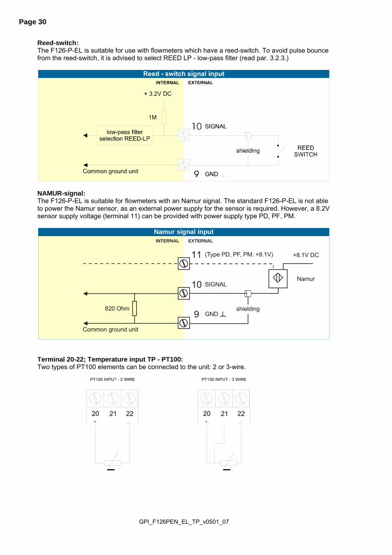
Reed-switch: The F126-P-EL is suitable for use with flowmeters which have a reed-switch. To avoid pulse bounce from the reed-switch, it is advised to select REED LP - low-pass filter (read par. 3.2.3.)
NAMUR-signal: The F126-P-EL is suitable for flowmeters with an Namur signal. The standard F126-P-EL is not able to power the Namur sensor, as an external power supply for the sensor is required. However, a 8.2V sensor supply voltage (terminal 11) can be provided with power supply type PD, PF, PM.
INTERNAL EXTERNAL
Namur signal input
10
Common ground unit
SIGNAL
9 GNDshielding
Namur
820 Ohm
11 (Type PD, PF, PM: +8.1V) +8.1V DC
Terminal 20-22; Temperature input TP - PT100: Two types of PT100 elements can be connected to the unit: 2 or 3-wire.

GPI_F126PEN_EL_TP_v0501_07
Page 31
Terminal 26-31: type CB / CH / CI / CT - communication RS232 / RS485 / TTL (option) Full serial communications and computer control in accordance with RS232 (length of cable
max. 15 meters) or RS485 (length of cable max. 1200 meters) is possible. Read the Modbus communication protocol and Appendix C.
Fig. 10: Overview terminal connectors communication option.
When using the RS232 communication option, terminal 27 is used for supplying the interface. Please connect the DTR (or the RTS) signal of the interface to this terminal and set it active (+12V). If no active signal is available it is possible to connect a separate supply between terminals 26 and 27 with a voltage between 8V and 24V. Terminal 26-31: backlight - type ZB (option): Note: if the unit is supplied with a power supply type PD, PF or PM, the backlight supply is integrated, so the text following is not applicable. To power the backlight, provide a 12-24V DC to terminal 26 (-) and 27 (+). An external trimmer 1kOhm trimmer can be used to tune the brightness of the backlight, or if not desired, a short-cut between these terminals have to be made which will result in the maximum brightness. Note: Intrinsically Safe as well as 4-wire RS485 communication is not possible in combination with type ZB.
Fig. 11: Overview terminal connectors backlight option.
30 3126 27
Power suppply12-24V DC 10%+
Option type ZB: adjustable backlight
+ +
+
1kOhm trimmer connectionor short-cut
GND
26 27 29
RS485 - 2-wire
28A B+
30 31Y
26 27Z
29
RS485 - 4-wire
28A B+
26 27 29
RS232
28RXD TXD
30 31 30 31DTR+12V

GPI_F126PEN_EL_TP_v0501_07
Page 32
5. INTRINSICALLY SAFE APPLICATIONS 5.1. GENERAL INFORMATION AND INSTRUCTIONS Cautions Mounting, electrical installation, start-up and maintenance of this device may only be carried out
by trained personnel authorized by the operator of the facility. Personnel must read and understand this Operating Manual before carrying out its instructions.
This device may only be operated by personnel who are authorized and trained by the operator of the facility. All instructions in this manual are to be observed.
Ensure that the measuring system is correctly wired up according to the wiring diagrams. Protection against accidental contact is no longer assured when the housing cover is removed or the cabinet has been opened (danger of electric shock). The housing may only be opened by trained personnel.
To maintain the degree of protection of at least IP65 in accordance with IEC 60529, certified cable entries in accordance with IEC 61241-0 must be used and correctly installed. Unused openings must be closed with suitable blanking elements.
When the enclosure of the Indicator is made of aluminum alloy, when used in a potentially explosive atmosphere requiring apparatus of equipment protection level Ga and Da, the unit must be installed such that, even in the event of rare incidents, an ignition source due to impact or friction sparks between the enclosure and iron/steel is excluded.
Take careful notice of the " Safety rules, instructions and precautionary measures " in the front of this manual.
Safety Instructions When two or more active intrinsically safe circuits are connected to the indicator, in order to
prevent voltage and/or current addition, applicable to the external circuits, precautions must be taken to separate the intrinsically safe circuits in accordance with IEC 60079-11.
For the combined connection of the different supply, input and output circuits, the instructions in this manual must be observed.
From the safety point of view the circuits shall be considered to be connected to earth. For installation under ATEX directive: this intrinsically safe device must be installed in
accordance with the Atex directive 94/9/EC and the product certificate KEMA 03ATEX1074 X. For installation under IECEx scheme: this intrinsically safe device must be installed in
accordance the product certificate IECEx DEK 11.0042X. Exchange of Intrinsically Safe battery FWLiBAT-0xx with certificate number
KEMA 03ATEX1071 U or IECEx KEM 08.0005U is allowed in Hazardous Area. See paragraph 5.4. for detailed battery replacement instructions.
Please Note Certificates, safety values and declaration of compliance can be found in the document named:
“Fluidwell F1..-..-XI - Documentation for Intrinsic Safety”. Special conditions for safe use mentioned in both the certificate and the installation instructions
must be observed for the connection of power to both input and / or output circuits. When installing this device in hazardous areas, the wiring and installation must comply with the
appropriate installation standards for your industry. Study the following pages with wiring diagrams per classification.

GPI_F126PEN_EL_TP_v0501_07
Page 33
Label information (inside and outside the enclosure) Indicated labels on the back cover (below) and on the inside cover (right) show the type labels for intrinsically safe certified units. For details on usage see the separate “Fluidwell F1..-..-XI Documentation for Intrinsic Safety”.
Serial number and year of production This information can be looked-up on the display: See setup function (par. 3.2.2.) for details. 5.2. TERMINAL CONNECTORS INTRINSICALLY SAFE APPLICATIONS The unit is classified as group IIB/IIIC by default. Classification of the unit as group IIC is only possible under the following conditions: The indicator is either supplied by
the internal supply (option -PC); or the external supply connected to terminals 0 and 1 (option -PD); or the circuit supply connected to terminals 7 and 8 (option -AP); The maximum values for any of those circuits are those as defined for group IIB/IIIC;
No other active external intrinsically safe circuits may be connected to the indicator, with exception of circuits connected to terminals 3 and 4 and/or terminals 5 and 6; the maximum values for any of those circuits are those as defined for group IIB/IIIC
Terminal connectors F126-P-EL-TP-XI:
ANALOG OUTPUTTYPE AF / AP
1+
2+
SENSOR SIGNALTYPE P:
PULSE INPUT
POWER SUPPLYTYPE PD
7 8I
GNDI
9 10SIGNAL
11+
2220
TEMPERATURE INPUTTYPE TP: PT100
+
21
Fig. 12: Overview terminal connectors XI - Intrinsically Safe applications.

GPI_F126PEN_EL_TP_v0501_07
Page 34
Explanation Intrinsically Safe options: Option AF - Intrinsically Safe floating 4-20mA analog output: A floating 4-20mA signal proportional to the flowrate is available with this option. When the output is disabled, a 3.5mA signal will be generated. Max. driving capacity 1000 Ohm @ 30V DC.
Type PD - Intrinsically Safe power supply and sensor supply - Terminal GND- 01 and 11.
OPTION SENSOR SUPPLY Terminal
GND 01 02
PD Input voltage:
8-30V DC 3,2 - 8,1V L- L+
output voltage is according the input voltage; internally linked with terminal 01.
Terminal 02: this terminal offers the same voltage as connected to terminal 01. Terminal 11: this terminal offers a 3.2V or 8.1V to power the sensor. This voltage is selected with the switch(es) inside the enclosure. First, remove the terminals after which the internal plastic cover can be removed.
Switch position Switch position terminal 11 no function
SWITCH 1 VOLTAGE SWITCH 2 on 8.1 V DC
not available off 3.2 V DC
Fig. 13: Switch position voltage selection option PD-XI.

GPI_F126PEN_EL_TP_v0501_07
Page 35
5.3 CONFIGURATION EXAMPLES
Fig. 14: Configuration example 1 Intrinsically Safe
TERMINAL CONNECTORSF100-series
HAZARDOUS AREA
Ci = 17nF
91
011
Common ground
Common ground
Signal
Supply *
Main supply
Circ
uit d
epen
ds o
n ty
pe o
f sig
nal
Power supply type PD: 16-30V DC
Analog output type AF:passive floating 4-20mA
RXD
Common ground
TXD
28
26
29
01
27
8
DTR+12V
27
e.g. countere.g. indicator
e.g. PC
e.g. indicator
Modbus communication type CT: TTL
Configuration example IIB - /IIIC F126-P-AF-CT-EL-(PC)-(PD)-TP-XI
Due to analog output type AF, the unit has to be powered with battery type PC or with external power supply type PD.
222
12
0
Supply
Signal
Signal
Temperature input type TP:
PT100 3-wire
Note: above values are safety values. Consult the technical specification for operational values.
SAFE AREA
IsolatorTTL to: RS232RS422
TTL
For example: MTL5051
I.S. Certified
+
-
+
-
Power supply and/or repeater
For example MTL5525MTL5541
Uo
Io
Po
= max. 30 V
= max. 100 mA
= max. 0.75 W
= max. 30 V
= max. 250 mA
= max. 0.85 W
Uo
Io
Po
+
-
Power supply
For example MTL5525
Uo
Io
Po
= max. 30 V
= max. 100 mA
= max. 0.75 W
Ci is negligiblysmall
Flowmeter input type: Ppulse
+
-
Power supply
For example MTL5525
Uo
Io
Po
= max. 30 V
= max. 100 mA
= max. 0.75 W
* Note power supply type PD: the supply voltage to the sensor is maximum 8.7V (Uo=8.7V Io=25mA Po=150mW)

GPI_F126PEN_EL_TP_v0501_07
Page 36
Fig. 15: Configuration example 2 Intrinsically Safe
TERMINAL CONNECTORSF100-series
HAZARDOUS AREA
Common ground
TOTAL OF ALL CONNECTEDAPPARATUS MAY NOT EXCEED
MINUS 17nF(17nF IS USED BY THE ANALOG
OUTPUT SIGNAL TERMINAL 7+ 8)
Co
66nF
Main supply Power supply type PD: 16-30V DC (please note: PD battery supply (type PC) is NOT allowed in IIC applications).and
RXD
Common ground
TXD
28
26
29
01
2
Ci = 17nF
Analog output type AF:passive floating 4-20mA
78
91
011
Common ground
Signal
Supply *
Circ
uit d
epen
ds o
n ty
pe o
f sig
nal
Modbus communication type CT: TTLPlease note: communciation type CT is allowed in IIC applications.not
DTR+12V
27
e.g. PC
e.g. indicator
Configuration example IIB/IIIC and IIC - F126-P-AF-(CT)-EL-PD-TP-XI
222
12
0
Supply
Signal
Signal
Temperature input type TP:
PT100 3-wire
Note: above values are safety values. Consult the technical specification for operational values.
SAFE AREA
IsolatorTTL to: RS232RS422
TTL
For example: MTL5051
I.S. Certified
+
-
= max. 30 V
= max. 250 mA
= max. 0.85 W
Uo
Io
Po
+
-
Power supply
For example MTL5525
Uo
Io
Po
= max. 30 V
= max. 100 mA
= max. 0.75 W
* Note: Communication only allowed when configured as IIB/IIIC.
Ci is negligiblysmall
Flowmeter input type: Ppulse
* Note power supply type PD: the supply voltage to the sensor is maximum 8.7V (Uo=8.7V Io=25mA Po=150mW)

GPI_F126PEN_EL_TP_v0501_07
Page 37
5.4 BATTERY REPLACEMENT INSTRUCTIONS Safety Instructions Fire, explosion or severe burns may result if mistreated. Do not recharge, crush,
disassemble, incinerate, heat above 100°C (212°F) or expose contents to water. Mounting, electrical installation, start-up and maintenance of this device may only be carried out
by trained personnel authorized by the plant operator. Personnel must read and understand this instruction before carrying out the replacement procedure.
Always follow the instructions listed in the supplied Battery Replacement Instruction Sheet. Batteries pose an environmental hazard. Return used batteries to a recycling point.
Safety instructions for hazardous areas Verify the correct battery is supplied: Only batteries with indicated Ex label are certified for
replacement and use in hazardous areas. Batteries for use in safe areas have no Ex label. DO NOT EXCHANGE: Using the wrong type of battery can pose a SERIOUS RISK.
For use in hazardous areas Fluidwell recommends FW-LiBAT batteries (manufactured by Fluidwell bv) only.
Battery replacement procedure
Depending on the production batch, one of two visualized Intrinsically Safe certified battery types may have been installed in the unit. They are interchangeable.
FW-LiBAT-001 battery FW-LiBAT-021 battery
1. To replace the battery, open the unit to gain access to the back inside cover of the unit. 2. Unplug the field connectors from the back inside of the unit. 3. Remove the screw that holds the plastic inside cover. 4. Open the cover and unplug the battery connector. 5. Remove the battery from the inside of the plastic cover. Do not remove the battery clip! 6. Install the new battery and re-assemble the unit in reverse order. 7. Start-up the unit

GPI_F126PEN_EL_TP_v0501_07
Page 38
6. MAINTENANCE 6.1. GENERAL DIRECTIONS Mounting, electrical installation, start-up and maintenance of the instrument may only be carried
out by trained personnel authorized by the operator of the facility. Personnel must read and understand this Operating Manual before carrying out its instructions.
The F126-P-EL may only be operated by personnel who are authorized and trained by the operator of the facility. All instructions in this manual are to be observed.
Ensure that the measuring system is correctly wired up according to the wiring diagrams. Protection against accidental contact is no longer assured when the housing cover is removed or the panel cabinet has been opened (danger from electrical shock). The housing may only be opened by trained personnel.
Take careful notice of the " Safety rules, instructions and precautionary measures " in the front of this manual.
The F126-P-EL does not require special maintenance unless it is used in low-temperature applications or surroundings with high humidity (above 90% annual mean). It is the users responsibility to take all precautions to dehumidify the internal atmosphere of the F126-P-EL in such a way that no condensation will occur, for example by placing dry silica-gel sachet in the casing just before closing it. Furthermore, it is required to replace or dry the silica gel periodically as advised by the silica gel supplier. Battery life-time: It is influenced by several issues : Type of sensor: read chapter 3.2.3. NPN and PNP inputs consume more energy than coil inputs. Input frequency: the higher the frequency, the shorter the battery life-time. Flowrate calculation: the lower number of pulses (SETUP 26) the shorter the battery life-time. Analog output signal; be sure that an external power supply is connected or that the function is
disabled if not in use; or else it will have a major influence on the battery life-time (SETUP 61). Display update: fast display update uses significantly more power; SETUP 41. Pulse output and communications . Low temperatures; the available power will be less due to battery chemistry. Note: It is strongly advised to disable unused functions. Check periodically: The condition of the casing, cable glands and front panel. The input/output wiring for reliability and aging symptoms. The process accuracy. As a result of wear and tear, re-calibration of the flowmeter and
temperature sensor might be necessary. Do not forget to re-enter any subsequent K-factor or Span alterations.
The indication for low-battery. Clean the casing with soapy-water. Do not use any aggressive solvents as these might damage
the coating.

GPI_F126PEN_EL_TP_v0501_07
Page 39
APPENDIX A: TECHNICAL SPECIFICATION
Display
Type High intensity reflective numeric and alphanumeric LCD, UV-resistant. Digits Seven 17mm (0.67") and eleven 8mm (0.31"). Various symbols and measuring units. Refresh rate User definable: 8 times/sec - 30 secs. Type ZB Transflective LCD with green LED backlight. Good readings in full sunlight and darkness.
Note: only available for safe area applications. Power requirements: 12-24V DC + 10% or type PD, PF, PM. Power consumption max. 1 Watt.
Enclosures
General
Control Keys Painting
Die-cast aluminum or GRP (Glassfibre Reinforced Polyamide) enclosure with Polycarbonate window, silicone and EPDM gaskets. UV stabilized and flame retardant material. Three industrial micro-switch keys. UV-stabilized silicone keypad. Aluminum enclosure only: UV-resistant 2-component industrial painting.
Panel-mount enclosures Classification Panel cut-out
Type HC Type HB
Dimensions: 130 x 120 x 60mm (5.10" x 4.72" x 2.38") – LxHxD. IP65 / NEMA4X 115 x 98mm (4.53" x 3.86") LxH. GRP panel-mount enclosure Aluminum panel-mount enclosure
Field/wall-mount enclosures Classification
Aluminium enclosures Type HA Type HM Type HN Type HO Type HP Type HT Type HU Type HV Type HZ
GRP enclosures Type HD Type HE Type HF Type HG Type HJ Type HH Type HK
Dimensions: 130 x 120 x 75mm (5.10” x 4.72” x 2.95”) – LxHxD. IP67 / NEMA4X Drilling: 2x PG9 – 1x M20. Drilling: 2x M16 – 1x M20. Drilling: 1x M20. Drilling: 2x M20. Drilling: 6x M12. Drilling: 1x ½”NPT. Drilling: 3x ½”NPT. Drilling: 4x M20 No drilling. No drilling. Drilling: 2x 16mm (0.63”) – 1x 20mm (0.78”). Drilling: 1x 22mm (0.87”). Drilling: 2x 20mm (0.78”). Drilling: 3x 22mm (0.87”). Drilling: 6x 12mm (0.47”). Flat bottom - no drilling.
Operating temperature
Operational -40°C to +80°C (-40°F to +176°F) Intrinsically Safe -40°C to +70°C (-40°F to +158°F)
Power supply
Type PB Lithium battery - life-time depends upon settings - up to 5 years. Type PC Intrinsically Safe lithium battery - life-time depends upon settings - up to 5 years. Type PD 8-24V AC / DC + 10%. Power consumption max. 10 Watt.
Intrinsically safe: 16-30V DC; power consumption max. 0.75 Watt. Type PF 24V AC / DC + 10%. Power consumption max. 15 Watt. Type PL Input loop powered from sensor signal 4-20mA (type A, non IS). Type PM 115-230V AC + 10%. Power consumption max. 15 Watt. Type PX Output loop powered: 8-30V DC. Power consumption max. 0.5 Watt.
Note PF / PM The total consumption of the sensors`, backlight and outputs may not exceed 400mA@24V. Note I.S. applications For intrinsically safe applications, consult the safety values in the certificate.
GENERAL

GPI_F126PEN_EL_TP_v0501_07
Page 40
Sensor excitation
Type PB / PC / PX 3.2V DC for pulse signals and 1.2V DC for coil pick-up. Note: This is not a real sensor supply. Only suitable for pulse sensors with a very low power consumption like coils (sine wave) and reed-switches.
Type PD 1.2 - 3.2 - 8.2 - 12 and 24V DC - max. 50mA@24V DC Type PD-XI Intrinsically safe: Pulse signals: 1.2 - 3.2 - 8.2 - max. [email protected] DC.
Analog signals: the sensor supply voltage is according to the power supply voltage connected to terminal 1. Also terminal 2 offers the same voltage.
Type PF / PM 1.2 - 3.2 - 8.2 - 12 and 24V DC - max. 400mA@24V DC. Terminal connections
Type: Removable plug-in terminal strip. Wire max. 1.5mm2 and 2.5mm2 (Type PM / PF)
Data protection
Type EEPROM backup of all setting. Backup of running totals every minute. Data retention at least 10 years.
Password Configuration settings can be password protected.
Hazardous area (option)
Intrinsically safe Type XI ATEX approval: II 1 G Ex ia IIB/IIC T4 Ga II 1 D Ex ia IIIC T100°C Da IP6x IECEx approval: Ex ia IIB/IIC T4 Ga Ex ia IIIC T100°C Da IP6x
Explosion proof Type XD/XF
ATEX approval ref.: <EX> II 2 GD EEx d IIB T5. Weight appr. 15kg. Dimensions of enclosure: 350 x 250 x 200mm (13.7” x 9.9” x 7.9”) LxHxD.
Directives & Standards
EMC Directive 2004/108/EC, FCC 47 CFR part 15Low voltage Directive 2006/95/EC ATEX / IECEx Directive 94/9/EC, IEC 60079-0, IEC 60079-11, IEC 60079-26IP & NEMA EN 60529 & NEMA 250
Flowmeter
Type P Coil/sine wave (minimum 20mVp-p or 80mVp-p - sensitivity selectable), NPN/PNP, open collector, reed-switch, Namur, active pulse signals 8 - 12 and 24V.
Frequency Minimum 0 Hz - maximum 7 kHz for total and flowrate. Maximum frequency depends on signal type and internal low-pass filter. E.g. Reed switch with low-pass filter: max. frequency 120 Hz.
K-Factor 0.000010 - 9,999,999 with variable decimal position. Low-pass filter Available for all pulse signals.
Type A (0)4-20mA - with signal calibration feature at any current within the range. Type U 0-10 V - with signal calibration feature at any voltage within the range.
Accuracy Resolution: 14 bit.. Error < 0.025mA / ±0.125% FS. Low level cut-off programmable. Span 0.000010 - 9,999,999 with variable decimal position.
Update time Four times a second. Voltage drop 2.5 Volt.
Load impedance 3kOhm Relationship Linear and square root calculation.
Note For signal type A and U: external power to sensor is required; e.g. Type PD.
INPUTS
GPI_F126PEN_EL_TP_v0501_07
Page 41
Temperature
Type TP 2 or 3 wire PT100. Standard range: -100°C to +200°C (-148°F to 392°F) - accuracy 0.1 °C (0.18°F).
Update time four times a second. Note The linearity is internally compensated.
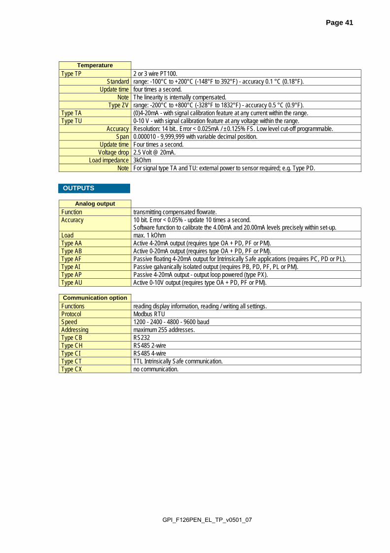
Type ZV range: -200°C to +800°C (-328°F to 1832°F) - accuracy 0.5 °C (0.9°F). Type TA (0)4-20mA - with signal calibration feature at any current within the range. Type TU 0-10 V - with signal calibration feature at any voltage within the range.
Accuracy Resolution: 14 bit.. Error < 0.025mA / ±0.125% FS. Low level cut-off programmable. Span 0.000010 - 9,999,999 with variable decimal position.
Update time Four times a second. Voltage drop 2.5 Volt @ 20mA.
Load impedance 3kOhm Note For signal type TA and TU: external power to sensor required; e.g. Type PD.
Analog output
Function transmitting compensated flowrate. Accuracy 10 bit. Error < 0.05% - update 10 times a second.
Software function to calibrate the 4.00mA and 20.00mA levels precisely within set-up. Load max. 1 kOhm Type AA Active 4-20mA output (requires type OA + PD, PF or PM). Type AB Active 0-20mA output (requires type OA + PD, PF or PM). Type AF Passive floating 4-20mA output for Intrinsically Safe applications (requires PC, PD or PL). Type AI Passive galvanically isolated output (requires PB, PD, PF, PL or PM). Type AP Passive 4-20mA output - output loop powered (type PX). Type AU Active 0-10V output (requires type OA + PD, PF or PM). Communication option
Functions reading display information, reading / writing all settings. Protocol Modbus RTU Speed 1200 - 2400 - 4800 - 9600 baud Addressing maximum 255 addresses. Type CB RS232 Type CH RS485 2-wire Type CI RS485 4-wire Type CT TTL Intrinsically Safe communication. Type CX no communication.
OUTPUTS

GPI_F126PEN_EL_TP_v0501_07
Page 42
Operator functions
Displayed functions • compensated total and/or compensated flowrate. • compensated total and compensated accumulated total. • line temperature. • compensated total can be reset to zero by pressing the CLEAR-key twice.
Total
Digits 7 digits. Units L, m3, GAL, USGAL, KG, lb, bbl, no unit. Decimals 0 - 1 - 2 or 3. Note total can be reset to zero.
Accumulated total
Digits 11 digits. Units / decimals according to selection for total.
Flowrate
Digits 7 digits. Units mL, L, m3, Gallons, KG, Ton, lb, bl, cf, RND, ft3, scf, Nm3, Nl, igal - no units. Decimals 0 - 1 - 2 or 3. Time units /sec - /min - /hr - /day.
Line temperature
Digits 7 digits. Units °C, °F or K Decimals 1 Normal temperature default: 273.15 K - any temperature can be set.
Flow equations
Type EL corrected liquid volumeFormula Qnormal = Q * (1 + α (Tnormal - T)) where α = thermal expansion coefficient.
OPERATIONAL

GPI_F126PEN_EL_TP_v0501_07
Page 43
APPENDIX B: PROBLEM SOLVING In this appendix, several problems are included that can occur when the F126-P-EL is going to be installed or while it is in operation. Flowmeter does not generate pulses: Check: Signal selection SETUP - 41, Pulse amplitude (par. 4.4.3.), Flowmeter, wiring and connection of terminal connectors (par. 4.4.3.), Power supply of flowmeter (par. 4.4.2.). Flowmeter generates "too many pulses": Check: Settings for total and Flowrate: SETUP 11-14 and 21-27, Type of signal selected with actual signal generated - SETUP - 41, Sensitivity of coil input - SETUP - 41 and par. 4.4.3. Proper grounding of the F126-P-EL - par. 4.4.1. Use screened wire for flowmeter signals and connect screen to terminal 9. (unless connected at
sensor) Analog output does not function properly: Check: SETUP 71 - is the function enabled? SETUP 72 / 73: are the flow-levels programmed correctly? connection of the external power-supply according to the specification. Flowrate displays "0 / zero" while there is flow (total is counting): Check: SETUP 22 / 25: are the K-factor and time unit correct? SETUP 26 / 27: The unit has to count the number of pulses according to SETUP 26 within the
time according to SETUP 27. Make sure that 27 is set to 10.0 seconds for example : the result is that the unit has at least 10 seconds time to measure the number of pulses according to SETUP 26.
The pass code is unknown: If the pass code is not 1234, there is only one possibility left: call your supplier. ALARM When the alarm flag starts to blink an internal alarm condition has occurred. Press the "select button" several times to display the 5-digit error code. The codes are: 0001: irrecoverable display-data error: data on the display might be corrupted. 0002: irrecoverable data-storage error: the programming cycle might have gone wrong: check
programmed values. 0003: error 1 and error 2 occurred simultaneously The alarm condition will almost certainly be handled internally and if all mentioned values still appear correct, no intervention by the operator is needed. If the alarm occurs more often or stays active for a longer time, please contact your supplier.

GPI_F126PEN_EL_TP_v0501_07
Page 44
APPENDIX C: COMMUNICATION VARIABLES GENERAL The tables below show the various variables that can be used for communication. The F126-P-EL is fitted with the Modbus communication protocol and can be equipped with various physical interfaces like RS485 and RS232 (please see device datasheet for available options). Currently, the functions supported are function 3 Read Holding Registers (4X references) and function 16 Preset Multiple Registers (4X references). The shown communication variables, indicated by the column VAR, show protocol addressed in decimal representation, followed by its hexadecimal representation (0x0000). When the PLC address range is required (4X references typically used by PLCs), please add a value of 40001 to the protocol address. E.g. reading the serial number with PLC-based addressing means reading 165 + 40001 = register 40166. Variables spanning multiple registers use ‘little-endian’ data representation. This means that the lowest register holds the least significant word of the variable. Although most Modbus masters will support variables that span 2 registers, variables spanning more registers sometimes require you to manually calculate the resulting value. Following example shows how data is represented and how this calculation can be accomplished:
For a total-value of 158928, the following register data has been received by the Modbus master: register 566 = 0x6CD0 = 27856 register 567 = 0x0002 = 2 register 568 = 0x0000 = 0 If we interpret this as a long integer value, it's value would be: 0x0000.0002.6CD0 = 158928. If this value needs to be calculated: 0*65536*65536 + 2*65536 + 27856 = 158928.
For additional information regarding using your Fluidwell Modbus device, please read the ‘Fluidwell General Modbus Communication Protocol’ and ‘Modbus troubleshooting guide’ that are available through our website or your distributor. RUNTIME VARIABLES OF THE F126-P-EL
VAR RUN-TIME VALUES REGs R/W TYPE VALUE / REMARKS 572
0x23C flow rate 2 r uint32 0…9999999
Representation: unit, time, decimals depending on variables 48, 49, 50
566 0x236
total 3 r uint48 0…9999999999 Representation: unit, decimals depending on variables 32, 33
560 0x230
accumulated total 3 r uint48 0…99999999999999 Representation: unit, decimals depending on variables 32, 33
37 0x025
error status 1 r uint16 Bitfield: 0x0001=Display error 0x0002=EEPROM error 0x0004=PT100 measurement error 0x0010=Correction factor calculation error (out of bounds) 0x0040=Totalizer calculation error (out of bounds)
Reading flowrate, total or accumulated total: The returned values are given including the decimals and represent the actual value. The given value may differ from the value that is displayed on the display – this is due to the fact that the display is limited in the number of digits and may have a slower update rate set. For example when two decimals are selected for total and total has a value of 123456,78 the display will show 23456,78 while communication will read a “total” of 12345678 and a “total decimals” of 2. Clearing total: It is possible to clear the total counter by means of writing a value of 0 to all the 3
registers of total in a single write action. Writing any other value will result in the reply of an error message.

GPI_F126PEN_EL_TP_v0501_07
Page 45
SETUP VARIABLES OF THE F126-P-EL
VAR TOTAL REGs R/W TYPE VALUE / REMARKS 32
0x020 unit 1 r/w uint8 0=none 1=L 2=m3
3=kg 4=lb 5=gal 6=usgal 7=bbl
33 0x021
decimals 1 r/w uint8 0…3
34 0x022
K-factor 2 r/w uint32 1...9999999 Representation: 0.000010…9999999 depending on variable 54: decimals K-factor.
37 0x025
decimals K-factor 1 r/w uint8 0…6
VAR FLOWRATE REGs R/W TYPE VALUE / REMARKS 48
0x030 unit 1 r/w uint8 0=mL 1=L 2=m3
3=mg 4=g 5=kg 6=ton 7=gal 8=bbl 9=lb 10=cf 11=rev 12=none 13=scf 14=NM3 15=NL 16=p
49 0x031
time unit 1 r/w uint8 0=sec 1=min 2=hour 3=day
50 0x032
decimals 1 r/w uint8 0…3
51 0x033
K-factor 2 r/w uint32 1...9999999 Representation: 0.000010…9999999 depending on variable 54: decimals K-factor.
54 0x036
decimals K-factor 1 r/w uint8 0…6
71 0x047
period time 2 r/w uint16 1...9999 steps of 100ms
62 0x03E
filter 1 r/w uint8 1...99
VAR DISPLAY REGs R/W TYPE VALUE / REMARKS 64
0x040 display function 1 r/w uint8 0=total 1=flowrate
VAR POWERMAN. REGs R/W TYPE VALUE / REMARKS 80
0x050 LCD update time 1 r/w uint8 0=fast 1=1sec 2=3sec
3=15sec 4=30sec 5=off 81
0x051 power mode 1 r/w uint8 0=operational 1=shelf
VAR FLOWMETER REGs R/W TYPE VALUE / REMARKS 96
0x060 flowmeter signal 1 r/w uint8 0=npn 1=npn-lp 2=reed
3=reed LP 4=pnp 5=pnp-lp 6=namur 7=coil hi 8=coil lo 9=act.8.1V 10=act. 12V 11=act.24V
VAR TEMPERATURE A/B REGs R/W TYPE VALUE / REMARKS 144
0x08D number of wires 1 r/w uint8 0= 2 wires
1= 3 wires 99
0x063 filter 1 r/w uint8 0….99
528 0x210
display 1 r/w uint8 0= °C 1= °F 2= K
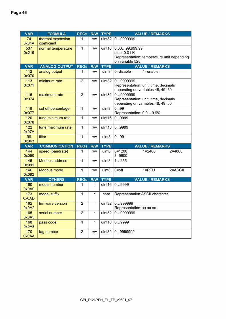
GPI_F126PEN_EL_TP_v0501_07
Page 46
VAR FORMULA REGs R/W TYPE VALUE / REMARKS 74
0x04A thermal expansion coefficient
1 r/w uint32 0…9999999
537 0x219
normal temperature 1 r/w uint16 0.00…99,999.99 step: 0.01 K Representation: temperature unit depending on variable 528
VAR ANALOG OUTPUT REGs R/W TYPE VALUE / REMARKS 112
0x070 analog output 1 r/w uint8 0=disable 1=enable
113 0x071
minimum rate 2 r/w uint32 0…9999999 Representation: unit, time, decimals depending on variables 48, 49, 50
116 0x074
maximum rate 2 r/w uint32 0…9999999 Representation: unit, time, decimals depending on variables 48, 49, 50
119 0x077
cut off percentage 1 r/w uint8 0...99 Representation: 0.0 – 9.9%
120 0x078
tune minimum rate 1 r/w uint16 0...9999
122 0x07A
tune maximum rate 1 r/w uInt16 0...9999
99 0x063
filter 1 r/w uint8 0...99
VAR COMMUNICATION REGs R/W TYPE VALUE / REMARKS 144
0x090 speed (baudrate) 1 r/w uint8 0=1200 1=2400 2=4800
3=9600 145
0x091 Modbus address 1 r/w uint8 1…255
146 0x092
Modbus mode 1 r/w uint8 0=off 1=RTU 2=ASCII
VAR OTHERS REGs R/W TYPE VALUE / REMARKS 160
0x0A0 model number 1 r uint16 0…9999
173 0x0AD
model suffix 1 r char Representation:ASCII character
162 0x0A2
firmware version 2 r uint32 0…999999 Representation: xx.xx.xx
165 0x0A5
serial number 2 r uint32 0…9999999
168 0x0A8
pass code 1 r uint16 0…9999
170 0x0AA
tag number 2 r/w uint32 0...9999999

GPI_F126PEN_EL_TP_v0501_07
Page 47
INDEX OF THIS MANUAL accumulated Total 8 actual settings 51 analog
floating output. 34 flowrate min. 18 intrinsically safe output. 34 output loop powered. 26
Analog output 26 Backlight 31 battery life time 15, 38 Clear Total 8 Coil-signal 28 communication 31
family-specific variables 44 Configuration 9 Dimension enclosures 21, 22 display
function 15 display update 15 expansion coeeficient 17 filter 17 flowmeter
signal 16 Flowmeter input 28 flowrate
calculation 14 decimals 14 decimals k-factor 14 measuring unit 14 time unit 14
Installation 20 Intrinsic safety 32 Intrinsically Safe options 34 IP classification 20
keys 7 low-battery 8 Low-battery alarm 8 main-function 10 maintenance 38 model 19 NAMUR-signal 30 Operator level 8 pass code 19, 43 power supply 25, 26 power supply intrinsically safe 34 pressure - normal 17 Problem solving 43 Pulse-signal active pulse 29 Pulse-signal NPN/PNP 28, 29 rate/Total 8 Reed-switch: 30 serial number 19 SETUP-level 9 subfunction 10 tagnumber 19 Technical specification 39 temperature - normal 17 temperature input 30 temperature settings 17 terminal connectors 25 time/date 8 total
decimals 13 decimals k-factor 13 k-factor 13, 14 measuring unit 13
version software 19
GPI_F126PEN_EL_TP_v0501_07
Page 48
LIST OF FIGURES IN THIS MANUAL Fig. 1: Typical application for the F126-P-EL. ...................................................................................... 5 Fig. 2: Control Panel. ............................................................................................................................ 7 Fig. 3: Example of display information during process. ........................................................................ 8 Fig. 4: Example of low-battery alarm. ................................................................................................... 8 Fig. 5: Dimensions aluminum enclosures. .......................................................................................... 21 Fig. 6: Dimensions GRP enclosures. .................................................................................................. 22 Fig. 7: Grounding aluminum enclosure with type PM 115-230V AC. ................................................. 23 Fig. 8: Switch setting sensor supply voltage. ..................................................................................... 24 Fig. 9: Overview of terminal connectors standard configuration F126-P-EL-TP and options. ........... 25 Fig. 10: Overview terminal connectors communication option. .......................................................... 31 Fig. 11: Overview terminal connectors backlight option. .................................................................... 31 Fig. 12: Overview terminal connectors XI - Intrinsically Safe applications. ........................................ 33 Fig. 13: Switch position voltage selection option PD-XI. .................................................................... 34 Fig. 14: Configuration example 1 Intrinsically Safe ............................................................................ 35 Fig. 15: Configuration example 2 Intrinsically Safe ............................................................................ 36

GPI_F126PEN_EL_TP_v0501_07
Page 49
DECLARATION OF CONFORMITY

GPI_F126PEN_EL_TP_v0501_07
Page 50
NOTES:

GPI_F126PEN_EL_TP_v0501_07
Page 51
LIST OF CONFIGURATION SETTINGS
SETTING DEFAULT DATE : DATE : 1 - TOTAL Enter your settings here 11 unit L 12 decimals 0000000 13 K-factor 0000001 14 decimals K-factor 0 2 - FLOWRATE 21 unit L 22 time unit /min 23 decimals 0000000 24 K-factor 0000001 25 decimals K-factor 0 26 period time 1.0 sec. 27 filter 0 3 - DISPLAY 31 function total 4 - POWER MANAGEMENT 41 LCD-new 1 sec. 42 mode operational 5 - FLOWMETER 51 signal coil-lo 6 - TEMPERATURE 61 no. of wires 3 62 filter 10 63 display unit °C 7 - FORMULA 71 equations EL EL EL 72 thermal exp. coefficient 0.000000 73 normal temperature 273.15 K K K8 - ANALOG OUTPUT 81 output disabled 82 rate min. (4-mA) 0000000 83 rate max. (20mA) 9999999 84 cut off percentage 0.0% 85 tune min (4mA) 0208 86 tune max (20mA) 6656 87 filter 01 (off) 9 - COMMUNICATION 91 speed (baud-rate) 2400 92 address 1 93 mode BUS-RTU A - OTHERS A1 model F126-P F126-P F126-P A2 software version A3 serial number A4 password 0000 A5 tagnumber 0000000

GPI_F126PEN_EL_TP_v0501_07
Page 52
Limited Warranty Policy
Great Plains Industries, Inc. 5252 E. 36th Street North, Wichita, KS USA 67220-3205, hereby provides a limited warranty against defects in material and workmanship on all products manufactured by Great Plains Industries, Inc. This product includes a 2 year warranty. Manufacturer’s sole obligation under the foregoing warranties will be limited to either, at Manufacturer’s option, replacing or repairing defective Goods (subject to limitations hereinafter provided) or refunding the purchase price for such Goods theretofore paid by the Buyer, and Buyer’s exclusive remedy for breach of any such warranties will be enforcement of such obligations of Manufacturer. The warranty shall extend to the purchaser of this product and to any person to whom such product is transferred during the warranty period.
The warranty period shall begin on the date of manufacture or on the date of purchase with an original sales receipt. This warranty shall not apply if:
A. the product has been altered or modified outside the warrantor’s duly appointed representative;
B. the product has been subjected to neglect, misuse, abuse or damage or has been installed or operated other than in accordance with the manufacturer’s operating instructions.
To make a claim against this warranty, contact the GPI Customer Service Department at 316-686-7361 or 888-996-3837. Or by mail at:
Great Plains Industries, Inc. 5252 E. 36th St. North,
Wichita, KS, USA 67220-3205
If you are outside North or South America contact:
Great Plains Industries – Australia 1/16 Atkinson Road,
Taren Point NSW 2229, Sydney, Australia
The company shall, notify the customer to either send the product, transportation prepaid, to the company at its office in Wichita, Kansas, or to a duly authorized service center. The company shall perform all obligations imposed on it by the terms of this warranty within 60 days of receipt of the defective product.
GREAT PLAINS INDUSTRIES, INC., EXCLUDES LIABILITY UNDER THIS WARRANTY FOR DIRECT, INDIRECT, INCIDENTAL AND CONSEQUENTIAL DAMAGES INCURRED IN THE USE OR LOSS OF USE OF THE PRODUCT WARRANTED HEREUNDER.
The company herewith expressly disclaims any warranty of merchantability or fitness for any particular purpose other than for which it was designed.
This warranty gives you specific rights and you may also have other rights which vary from U.S. state to U.S. state. Note: In compliance with MAGNUSON MOSS CONSUMER WARRANTY ACT – Part 702 (governs the resale availability of the warranty terms).


![Untitled-1 [] F134 F121 F122 F123 F124 F125 F126 F127 F99 F100 F110 F111 F112 F113 F101 F102 F103 F114 F115 F116 F117 F104 F105 F106 F1 ...](https://static.fdocuments.in/doc/165x107/5ab0244e7f8b9a22118e174e/untitled-1-f134-f121-f122-f123-f124-f125-f126-f127-f99-f100-f110-f111-f112-f113.jpg)