FLOW MEASUREMENT TECHNOLOGY Solutions for Fluid Technology
22
Solutions for Fluid Technology VS SERIES FLOW MEASUREMENT TECHNOLOGY
Transcript of FLOW MEASUREMENT TECHNOLOGY Solutions for Fluid Technology

Solu
tio
ns f
or
Flu
id T
echn
olo
gy
VS SERIES
FLOW MEASUREMENT TECHNOLOGY

2
VSI-HIGH DEFINITION PREAMPLIFIER• The VSI High Definition Preamplifier supplies digital signals with a higher resolution of the measured value. The resolution can be programmed between 4 and 64 angle steps and it enables a frequency multiplication up to factor 16. The K-factor of the flow meter can be increased up to factor 64. The maximum frequency at full flow can be 26 kHz.
EX-TYPES• Intrinsically safe models, with approval code l 1G EEx ia llC T4-T6, are supplied for applications in poten-tially hazardous areas. VSE delivers these types with isolation switch amplifier models MK 13 P Ex Ex 0/ 21 VDC / K15.
VS POSITIVE DISPLACEMENT FLOW METERS
VS FLOW METER• VS positive displacement flow meters are volume rate measuring sensors based on the meshing gear principleand are designed for use with liquids. Two precisely matched gear wheels are enclosed in a very accurately machined housing. Gear rotation is sensed by a non-contacting signal pick-up system. Each tooth produces one impulse.
• The space between the gear teeth, when fully enclosed on both sides by the housing, constitute measuringchambers. Fluid flow causes the gears to rotate and the incoming flow is separated into discrete volumes within these chambers i. e. the volume of liquid passing through the unit will cause rotation of the gears by exactly onetooth pitch.
• This volume is known as the Volume/Impulse (Vm) and is stated in cc/Imp. It is used to define the size of a flow meter.
EXPLANATIONS TO PREAMPLIFIER OF SIGNAL PICK-UP SYSTEM• The non-contact pick-up sensors consist of two differentialmagneto resistors which are circumferentially offset from one another by 1/4 of a tooth pitch. The signals of both pick-up sensors are digitized with two signal amplifiers and amplified via followed shortcircuit proof push-pull output stages.The square wave output signals are bidirectional and may be simply processsed by any external electronics, plc controlor computer. The processing of the 90° phase angle between signals enables recognition of flow directionand impulse rate conversion with a factor of 1, 2 and 4.
• The signal frequency is proportional to the momentary flow rate (volume rate) dependent on the particular flowmeter size. The frequency range extends from 0 - 2000 Hz. The preamplifier is protected against reverse polarityand incorrect connection. For medium temperatures bet-ween -30° C and 120° C (-22° F and 248° F) the unit is mounted directly on the flow meter cover.
• For liquid temperatures up to 210° C (410° F) a special pick up system is available.
VS FLOW METER SELECTION• For trouble-free and safe operation of the flow meters the correct selection of type and size is decisive. Due to the great number of different applications and flow meterversions, the technical data in the VSE-catalogues are of general character. Certain characteristic of the devices depend on type, size and measuring range as well as on the medium to be measured. For exact flow meter selection please contact VSE.

3
BLOCK DIAGRAM
OUTPUT SIGNALS OF PREAMPLIFIER
FLOW METER VS 0,02... VS 4 FLOW METER VS 10
* VOLTAGE RANGES supply voltage: UV = 10 .... 28 V DC impulse voltage: Upp= UV - 1V
Gear rotation of one tooth pitch
One impulse
Volume / impulse in cm3 / Imp
Channel 1
Channel 2
Channel offset by 1/4 oftooth pitch (90°)
Impulse mark/space ratio(adjust. at preamplifi er)
Flow in direction 1 Flow in direction 2
Up
p
* VOLTAGE RANGES supply voltage: UV = 10 .... 28 V DC impulse voltage: Upp= UV - 1V
+ Volts
Channel 1
0 Volts
Channel 2
brown
white
blue
black
Pro
cess
or U
nit
Signal Amplifi ers Push-pulloutputstages Potential equalization

4
APPLICATIONS• All liquids that can be pumped and have known lubrication properties can be measured, for example: Petrol, parafin, kerosene, diesel; Skydrol, mineral oils, hydraulic oils including fire resistant fluids; inks, dyes and paints; greases; polyurethane, polyol and isocyanates; Araldite; glues, pastes and creams; resins; waxes ... and many others.
RANGES OF APPLICATIONS IN THE AUTOMOTIVE INDUSTRY• Braking system test stands• Fuel consumption measurement• Polyurethane foams for steering wheels, fascia, seats etc.• Paint spraying systems• Steering systems• Batching and filling of motor oils, brake fluids, anti-freeze, rust preventatives, waxes etc.• Adhesive coatings for windscreens, headlights, engine housings etc.
HYDRAULICS• Volume and flow rate measurement • Leakage and rupture monitoring • Cylinder speed and position measurement• Positioning and step control• Measurement, control and regulation of flow rates and volumes• Test stands for pumps, motors, valves, proportionals and servo-valves• Synchronised multi-cylinder monitoring• Filling and additive blending
DYES AND PAINTS• Paint spraying systems• Batching and filling• Volume, flow rate and consumption• Monitoring of mixing ratios
PLASTICS TECHNOLOGY• Mixing, moulding and batching systems for single and multicomponent fluidplastics• Consumption measurement of e.g. : Epoxy adhesives and potting compounds (resins and hardeners) for transformers, coils, relays, condensers, armatures, initiators, auto-electronics• Measuring, control and regulation of single components and mixing ratios• Silicon potting compounds • Polyurethane foams (polyol and isocyanate) for steering wheels, seals, shoes, soles, surf boards, furniture, computer casings, isolation etc.• hot adhesive
CHEMICAL INDUSTRY• Flow rate and volume measurement in process plant and plant systems• Blending and filling chemical products such as liquid plastics adhesives, resins, hardeners, potting, compounds, solvents, fuels, foames plasticisers, dyes and paints, oils and synthetic products etc. application in laboratories and manufacturing plants (in normal and hazardous areas)• Control and regulation of single components, mixing ratios and consumption of various components• Leakage measurement and leakage monitor on plant• Measurement, indication and logging of data for product quality assurance
SPECIAL DESIGNS ON REQUEST• The issue of this catalogue invalidates all specifi- cations in earlier publications. Changes and deviations are reserved by VSE. VSE will not accept liability for printing errors. Reproduction, including excerpts, is only permitted with written permission by VSE. Revision: 09/2007
RANGES OF APPLICATIONS

5
Accuracy ± 0.3 % of measured value at viscosity > 20 cSt (< 20 cSt reduced accuracy)
Repeatability ± 0.05 % under same operating conditions
Materials Body
EN-GJS-400-15 (EN 1563) Stainless Steel 1.4305
Bearings
Ball / Plain / Plain (Copper-free) depend on liquid.
Seals
FPM (Standard)
NBR, PTFE, EPDM
Max. Operating Pressures Cast Iron
315 bar/4568 psi
Stainless Steel
450 bar / 6526 psi
Medium Temperature Standard –30 ≤ ... 120° CEx-design –20 ≤ ... 100° CHigh temperature –40 ≤ ... 210° C
Viscosity Ranges 1...100 000 cSt
Mounting Positions unrestricted, on subplate with side or bottom connections
Filteringfor ball bearing type
VS 0.02/0.04/0.1 10 µm VS 0.2/0.4 20 µm VS 1/2 50 µm
VS 4 50 µm
Exceptions
flow meter with special clearance on request.
Noise Level max. 72 dB(A)
Preamplifier 10 to 28 Volt (DC)
TECHNICAL DATA OVERVIEW
CALCULATION FACTOR• 1 litre = 0.26417 U.S.Gallon•1 U.S.Gallon = 3.78544 litre•1 bar = 14.503684 psi•1 psi = 0.068948 bar
psi = pound-weight per square inch
GPM = U.S.Gallon per minute
°C =
°F = + 32
5 X (°F - 32) 9
9 x °C 5
Accuracy ± 0.3 % of measured value at viscosity > 20 cSt (< 20 cSt reduced accuracy)
Repeatability ± 0.05 % under same operating conditions
Materials Body
EN-GJS-400-15 (EN 1563)Stainless Steel 1.4305
Bearings
Ball / Plain / Plain (Copper-free) depend on liquid.
Seals
FPM (Standard)
NBR, PTFE, EPDM
Max. Operating Pressures Cast Iron
315 bar/4568 psi
Stainless Steel
450 bar / 6526 psi
Medium Temperature Standard –30 ≤ ... 120° CEx-design –20 ≤ ... 100° CHigh temperature –40 ≤ ... 210° C
Viscosity Ranges 1...100 000 cSt
Mounting Positions unrestricted, on subplate with side or bottom connections
Filteringfor ball bearing type
VS 0.02/0.04/0.1 10 µm
VS 0.2/0.4 20 µm VS 1/2 50 µm
VS 4 50 µm
Exceptions
flow meter with special clearance on request.
Noise Level max. 72 dB(A)
Preamplifier 10 to 28 Volt (DC)
SizeFlow Range* Flow Range* K-Factor K-Factor
l / min GPM l / min Imp. / Gal.
VS 0.02 0.002 .......... 2 0.0005 ...... 0.53 50 000 189272
VS 0.04 0.004 .......... 4 0.0011 ....... 1.06 25 000 94636
VS 0.1 0.01 ......... 10 0.0026 ...... 2.64 10 000 37854.4
VS 0.2 0.02 ......... 18 0.0053 ...... 4.76 5 000 18927.2
VS 0.4 0.03 ........ 40 0.0079 .... 10.57 2 500 9463.6
VS 1 0.05 ........ 80 0.0132 ..... 21.13 1 000 3785.44
VS 2 0.1 ....... 120 0.0264 .... 31.70 500 1892.72
VS 4 1 ..... 250 0.2642 .... 66.00 250 946.36
VS 10** 1.5 ...... 525 0.39 ....... 138.00 300 1135
*at 21 cSt *at 21 cSt

6
FLOW RESPONSE CURVES
flow
resis
tanc
e ∆
p
flow rate Q
flow
resis
tanc
e ∆
p
flow
resis
tanc
e ∆
pflo
w re
sista
nce
∆ p
flow
resis
tanc
e ∆
p
flow
resis
tanc
e ∆
pflo
w re
sista
nce
∆ p
flow
resis
tanc
e ∆
pVS 0.1 VS 0.2
VS 1VS 0.4
VS 4VS 2
VS 0.02 VS 0.04
flow rate Q
flow rate Q flow rate Q
flow rate Q flow rate Q
flow rate Q flow rate Q

7
to andandto
r
Size
VS / VSIA B C D E ø G H K L M N O-ring
Weight
GG
kg
0.02 100 80 91 M 6 12.5 ø 9 114 58 70 40 20 11 x 2 2.8
0.04 100 80 91.5 M 6 11.5 ø 9 114.5 58.5 70 40 20 11 x 2 2.8
0.1 100 80 94 M 6 9 ø 9 117 61 70 40 20 11 x 2 2.8
0.2 100 80 93.5 M 6 9.5 ø 9 116.5 60.5 70 40 20 11 x 2 3.0
0.4 115 90 96.5 M 8 11.5 ø 16 119.5 63.5 80 38 34 17.96 x 2.62 4.0
1 130 100 101 M 8 12 ø 16 124 68 84 72 34 17.96 x 2.62 5.3
2 130 100 118 M 8 15 ø 16 141 85 84 72 34 17.96 x 2.62 6.7
4 180 140 143 M 12 20 ø 30 166 110 46 95 45 36.17 x 2.62 14.7
• GG = Cast Iron EN-GJS-400-15 (EN 1563)• E = Stainless Steel 1.4305• Dimensions are specified in mm
CAST IRON VERSION• Housing curve mill cutted
CAST IRON VERSION CONNECTION DRAWING• View X
Flow meter
Subplate
Flow meter
Subplate
SIDE PORTS BOTTOM PORTS
VS FLOW METER DIMENSIONS
to andandto
r
STAINLESS STEEL VERSIONCONNECTION DRAWING• Housing not mill cutted• View X
Grounding
Centre bores
Grounding
Plug direction for
Plug direction for
Centre bores

8
SIDE PORTS BOTTOM PORTS *
Cast Iron / APG.S... /. Stainless Steel / APE.S... / . Cast Iron / APG.U... /. Stainless Steel / APE.U... / .
AFFILIATED
SIZE
VS / VSI
G PIPE THREAD
CLASSIFICATION
G F ø H E
0.02 / 0.04
0.1 / 0.2
G 1 / 4 35 ø 20 26
0.02 / 0.04
0.1 / 0.2
G 3 / 8 35 ø 23 30
0.02 / 0.04
0.1 / 0.2
0.4 / 1 / 2
G 1 / 2
G 1 / 2
35
35
ø 28
ø 28
38
46
0.4 / 1 / 2 G 3 / 4 40 ø 33 52
1 / 2 G 1“ 55 ø 41 55
4 G 1 1 / 4 70 ø 51 60
4 G 1 1 / 2 AP..U=70 ø 56 72
4 G 1 1 / 2 AP..S=80 ø 56 72
* Both bottom ports (G) for size APG 4 U and APE 4 U have a displacement of 90° to the shown drawings.
Size Depth Weight
VS / VSI AP A B C D L M kg
0.02 / 0.04
0.1 / 0.2
AP.02 80 90 40 70 100 M6/12 1.8
0.4 AP.04 90 100 38 80 115 M8/15 2.7
1 / 2 AP.1 100 110 72 84 130 M8/15 3.6
4 APG4
APG4 UG
APE.4
120
140
140
130
120
–
100
120
100
110
100
110
–
–
180
M8/15
M8/15
M8/15
7.4
7.4
12
AP SUBPLATE DIMENSIONS
1
2
2
1 Only for APG.U ... / . ; APE.U ... / .Only for APE.S ... / . ; APE.U ... / .
Special designs on request
AFFILIATED
SIZE
VS / VSI
G PIPE THREAD
CLASSIFICATION
G F ø H E
0.02 / 0.04
0.1 / 0.2
G 1 / 4 35 ø 20 26
0.02 / 0.04
0.1 / 0.2
G 3 / 8 35 ø 23 30
0.02 / 0.04
0.1 / 0.2
0.4 / 1 / 2
G 1 / 2
G 1 / 2
35
35
ø 28
ø 28
38
46
0.4 / 1 / 2 G 3 / 4 40 ø 33 52
1 / 2 G 1“ 55 ø 41 55
4 G 1 1 / 4 70 ø 51 60
4 G 1 1 / 2 AP..U=70 ø 56 72
4 G 1 1 / 2 AP..S=80 ø 56 72
11
Size Depth Weight
VS / VSI AP A B C D L M kg
0.02 / 0.04
0.1 / 0.2
AP.02 80 90 40 70 100 M6/12 1.8
0.4 AP.04 90 100 38 80 115 M8/15 2.7
1 / 2 AP.1 100 110 72 84 130 M8/15 3.6
4 APG4
APG4 UG
APE.4
120
140
140
130
120
–
100
120
100
110
100
110
–
–
180
M8/15
M8/15
M8/15
7. 7. 74
7. 7. 74
12
22

9
VS 10 FLOW METER
Size Flow range l / min GPM K-Factor Imp. / l
Imp. / Gal.
VS 10 1.5 ... 525 0.3963 ... 138.69 300 1135.63
Accuracy ± 0.3 % of measured value at viscosity > 20 cSt (< 20 cSt reduced
accuracy)
Repeatability ± 0.05 % under same operating conditions
Materials Body Bearings Seals
EN-GJS-600-3EN 1563
Ball / Plain gearings depend on liquid.
FPM (Standard)NBR, PTFE, EPDM
Max. Operating Pressure 400 bar / 6000 psi
Medium Temperature Standard –30 ≤ ... 120° CEx-design –20 ≤ ... 100° CHigh temperature not available
Viscosity Range 1 ... 100 000 mm2 / s
Mounting Positions unrestricted, on subplate with side or bottom connections
Filtering 50 µm
Preamplifi er short circuit proof and reverse polarity proof 10 ... 28 V DC / 45 mA, additional current on signal output max. 20 mA
OUTPUT SIGNALS OF PREAMPLIFIER
VOLTAGE RANGESSupply voltages: Uv = 10 ... 28 V DCImpulse voltages: Uss = Uv – 1 V
TECHNICAL DATA
Accuracy ± 0.3 % of measured value at viscosity > 20 cSt (< 20 cSt reduced
accuracy)
Repeatability ± 0.05 % under same operating conditions
Materials Body Bearings Seals
EN-GJS-600-3EN 1563
Ball / Plain gearings depend on liquid.
FPM (Standard)NBR, PTFE, EPDM
Max. Operating Pressure 400 bar / 6000 psi
Medium Temperature Standard –30 ≤ ... 120° CEx-design –20 ≤ ... 100° CHigh temperature not available
Viscosity Range 1 ... 100 000 mm2 / s
Mounting Positions unrestricted, on subplate with side or bottom connections
Filtering 50 µm
Preamplifi er short circuit proof and reverse polarity proof 10 ... 28 V DC / 45 mA, short circuit proof and reverse polarity proof 10 ... 28 V DC / 45 mA, short circuit proof and reverse polarity proofadditional current on signal output max. 20 mAshort circuit proof and reverse polarity proofadditional current on signal output max. 20 mAshort circuit proof and reverse polarity proof 10 ... 28 V DC / 45 mA, additional current on signal output max. 20 mA
10 ... 28 V DC / 45 mA, short circuit proof and reverse polarity proof 10 ... 28 V DC / 45 mA, short circuit proof and reverse polarity proofadditional current on signal output max. 20 mAshort circuit proof and reverse polarity proof 10 ... 28 V DC / 45 mA, short circuit proof and reverse polarity proof

10
FLOW RESPONSE CURVES
DIMENSIONS
SUBPLATE DIMENSIONS
flow
resis
tanc
e ∆
p
Dimensions are specified in mm
Dimensions are specified in mm
APG 10 S GON / 1 APG 10 S WON / 1
flow rate Q

11
VSE FLOW METERS IN EX-DESIGN / THE BARRIER AMPLIFIER
THE BARRIER AMPLIFIER MK 13-P-EX 0 / 24 VDC / K15The barrier amplifier MK 13-P-Ex 0/24 VDC/K15 makes a galvanic isolated transmission of binary switching status possible. It has an intrinsically safe control circuit and is certified according to II(1) GD (EExial) IIC.There is a galvanic separation from the control circuit to the output circuit and to the power supply. For the transmission of two channels, two barrier amplifiers of this version are necessary. The control circuit can be monitored concerning wire breaking and short circuit (the monitoring can be switched off via a wire jumper).An error in the control circuit stops the signal output but is not displayed as an error message. Two plus-switching (PNP-outputs) short circuit proof transistor outputs display the digital signal of a channel antivalently.
Flow meter VSE connection cable, blue, PUR, Barrier amplifi er
Typ VS****–32 Q1* / * shielded; 4 x 0,34 mm2 Typ MK 13-P-Ex 0 / 24 VDC / K15
BVS 05 ATEX E 071 X PUR PTB 06ATEX 2025
ll 1G EEx ia ll C T4-T6 ll (1) G [EEx ia] ll C
Ui = 18,5 V R = 0,053 Ω / m Uo = 9,9 V
Ii = 24 mA L = 0,85 µH / m (x) Io = 22 mA
Pi = 100 mW CA-A = 55 pF / m (x) Po = 54 mW
Ri = 0 CA-S = 105 pF / m (x)
Li = 0 [(x) = measured at1000 Hz]
Ci = 0,27 µF llC llB
Lo / mH 1 5 10 2 10 20
Co / µF 1,5 0,75 0,65 5 3,5 3
ll 1G EEx ia ll C T4-T6
temperature class T4 T5 T6
ambient temperature - 20 ° C ≤ Tamb ≤ 95° C - 20 ° C ≤ Tamb ≤ 70° C - 20 ° C ≤ Tamb ≤ 55° C
liquid temperature - 20 ° C ≤ TMed ≤ 100° C - 20 ° C ≤ TMed ≤ 75° C - 20 ° C ≤ TMed ≤ 60° C
VSE FLOW METERS IN EX-DESIGNThe VSE flow meters of the VS-series in ex-design are approved for applications in potentially hazardous areas and are always operated in conjunction with one or two barrier amplifiers. They have blue markings and offer the necessary Ex-protection security. The type plate shows the necessary description according to DIN EN 50014, the type key and the safety-related and electric data. VSE can supply the flow meters with the barrier amplifiers type MK 13-P-Ex 0/24 VDC/K15.

12
OPTION FOR STAINLESS-STEEL
FLOW METERS VS 0,04 … VS 4• The pick-up system consists of one or two sensor units which are screwed into the cover of the VS flow meter and of a downstream switched amplifier. This amplifier is connected with the flow meter by means of a temperature resistant cable and has to be installed outside the high temperature area, where the ambient temperature should not exceed 50°C (122°F).
• Depending on the amplifier version, the digital signals are output as PNP or NPN switching signals. The fol-lowing pictures show the respective connection of the electronic readout:
•For long cable lengths and high input impedance of the read out it is recommended to use shielded cables and a pull-down (PNP-signal) or a pull-up (NPN-signal) resistors.
CONNECTION: PNP-SWITCHING
CONNECTION: NPN-SWITCHING
PICK-UP SYSTEM FOR HIGH TEMPERATURE RANGES
Flow meter Amplifier Electronicreadout
MeasuringControlling
PNP-Signal plus switching
NPN-Signal minus switching

13
TECHNICAL DATA / FLOW METER DIMENSIONS
Medium Temperature –40° C ... 210° C
Number of pick-ups 1 or 2 pick-ups
Pick-up Magnetoresistive
Electrical Connection PG– cable fitting
Isolation-Protection IP 64
Supply Voltage Ub = 10 ... 30 V DC +/–10-%
Current Consumption Ib = ca. 15 mA (idle motion, without load)
Signal Output PNP High Sign: –Us = Ub –1 V, ls = 25 mA max.
Signal Output NPN Low Sign: –Us = 0V, ls = 25 mA max.
Electrical Connection 4-pole round plug M 12
Max. Ambient Temperature 50° C
Protection-class IP 64
Pull-down Resistor 4.7 ... 10 KΩ
Pull-up Resistor 4.7 ... 10 KΩ
TECHNICAL DATA: SENSOR UNIT
TECHNICAL DATA: AMPLIFIER
Centre bores
Amplifier
Cable lenght
r
FLOW METER DIMENSIONS VIEW X
Size A D E ø G K L M N P O-ringWeight
kg
VS 0.04* 100 M 6 11.5 ø 9 58.5 70 40 20 22 11 x 2 3.5
VS 0.1 100 M 6 9 ø 9 61 70 40 20 22 11 x 2 3.3
VS 0.2 100 M 6 9 ø 9 60.5 70 40 20 22 11 x 2 3.6
VS 0.4 115 M 8 11.5 ø 16 63.5 80 38 34 22 17.96 x 2.62 4.9
VS 1 130 M 8 15 ø 16 68 84 72 34 22 17.96 x 2.62 6.7
VS 2 130 M 8 12 ø 16 85 84 72 34 22 17.96 x 2.62 8.3
VS 4 180 M 12 20 ø 30 110 46 95 45 12 36.17 x 2.62 18.3
*Attention: * 0.04 with one (1) channel only

14
TYPE KEY FLOW METERS VS
TYPE KEY
EXAMPLE
15
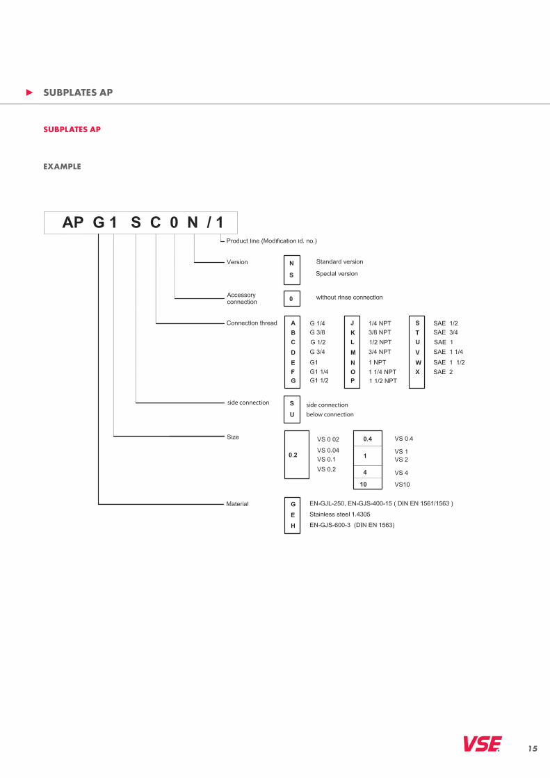
SUBPLATES AP
SUBPLATES AP
side connection
below connection
side connection
EXAMPLE

16
FLOW METERS WITH HIGH DEFINITION PREAMPLIFIER
FLOW METERS WITH HIGH DEFINITION FLOW RATEThe preamplifiers of the standard version for flow meters of the “VS” product line output one pulse per tooth-gap volume VZ, which corresponds to the volume measurement Vm (Vm = VZ / pulse.). This occurs in two channels, so that a maximum resolution of 1/4 VZ for the evaluation of all flanks can be attained. A higher resolution is not possible with these preamplifiers.But since as high a resolution as possible is necessary for precise and exact flow and volume measurements, the volume measurement Vm must be resolved even more than is the case with conventional preamplifiers. VSE has therefore developed the preamplifier with interpolation, with which a selectable resolution of up to 64 flanks (16 pulses) per period can be attained. This means that you can resolve the volume measurement Vm with this preamplifier to a maximum of 1/64 Vm. For the evaluation, this means that a part volume of 1/64 Vm from pulse flank to pulse flank (for quadruple evaluation or flank count) is measured, or a full signal pulse is counted as part volume of 1/16 Vm (pulse count) (interpolation Vm/16).
This individually programmed high resolution enables you to set the volume measurement Vm optimally for each provided case of application. Furthermore, new applicati-ons can be availed of with the higher resolution
Measuring, controlling and regulating in lower flow ranges
Measuring, controlling and regulating in zero flow Measuring, controlling and regulating in both flow
directions Measuring, controlling, dosing and filling of small
volumes
Flow meters with interpolation electronics (VSI) output two digital signals with programmable high resolution that are phase-offset 90°. In addition to the signal emission, a zero signal emission is provided which emits a zero signal at each fully registered volume measurement Vm.
FIGURE SIGNAL EMISSION OF THE PREAMPLIFIER WITH INTERPOLATIONFig. shows the resolution of the volume measurement Vm with an interpolation factor of 8. This resolves each volume measure- ment into eight individual part volumes. A pulse on the signal output of channel 1 or channel 2 thus has a value of Vm* = Vm/ 8 = 1/8 Vm per pulse. In double evaluation (flank evaluation of one channel) this results in a value of 1/2 Vm* = Vm / 16 = 1/16 Vm and for quadruple evaluation (flank evaluation of both channels) the result is a value of
1/4 Vm* = Vm / 32 = 1/32 Vm per flank. Evaluation electronics can recognize flow direction from signals offset 90°.The preamplifier of the “VSI” product line has a programmed interpolation factor (IPF) with which you can program new, different resolutions. Hence you can program a reso-lution of 4 to 64 angular steps (see Fig. 4) per volume measurement Vm. The frequency multiplication “f*” lies between 1 and 16 (see table).

17
INTERPOLATION FACTOR AND RESOLUTION
Interpolation factor
Imp/VmMax. resolution(evaluation of signal
flanks)
Resolution Vm*(volume measurement
Vm*) [ml]
Max. resolution(angle degrees)
Frequency fmax*
1 1 4 (quadrupling) Vm / 4 90° fmax x 1
2 2 8 Vm / 8 45° fmax x 2
3 3 12 Vm /12 30° fmax x 3
4 4 16 Vm /16 22.5° fmax x 4
5 5 20 Vm /20 18° fmax x 5
8 8 32 Vm /32 11.25° fmax x 8
10 10 40 Vm /40 9° fmax x 10
12 12 48 Vm /48 7.5° fmax x 12
16 16 64 Vm /64 5.625° fmax x 16
Column 1: programmable interpolation factor IPF (programming is done in the factory)Column 2: Pulses per volume measurement Vm
Column 3: maximum resolution of the signal flanks. The signal flanks channels 1 and 2 are evaluated.Column 4: Volume measurement Vm
* resulting from the maximum resolution of the signal flanks.Column 5: maximum resolution in angle degrees at resolution of signal flanks.Column 6: maximum frequency fmax* at maximum flow Qmax and programmed interpolation factor IPF
In practice, the maximum flow Qmax of the flow meter is seldom run, so that a lower frequency can be calculated. The maximum frequency is then calculated according to the following formula:
fmax* Maximum frequency of the flow meter signalsQmax° Maximum flow attained in the case of application described hereIPF Programmed interpolation factor Vm Volume measurement of the flow meter
Example: Flow meter VSI 1/10… max. flow rate of the system at maximum capacityQmax° = 40 l/min = 666.667 ml/sec; IPF = 10; Vm = 1 ml/pulse; fmax° = 6666.67 Hz = 6.66667 kHz
At max. flowmax* = 40 l/min, the flow meter VSI 1/10… outputs a frequency of f max* = 6666.67 Hz.
fmax*=(Qmax°)*IPF
Formel 1 Vm

18
TYPE KEY FLOW METERS VSI
TYPE KEY
EXAMPLE

19
ELECTRONIC DISPLAYS WITH ANALOGUE OUTPUT
• Flow meter type selectable by menu• Flow meter direction indicatior• 16 Bit-analogue output 0 … ± 10 V 0 … ± 20 mA 0/4 …20 mA• 2 limit value outputs • Semiconductor• PC-Interface RS 232 or RS 485• A power supply for flow sensor is integrated 24 Volt DC/100mA
• Flow direction indication with switching output (0 V / 5 V)• 2 optocoupler limit value outputs, limit value are indivi- dually programmable• Analogue output with flow rate direction dependent voltage-/ current-polarity is avaible 0 … (±) 10 V 0 … (±) 20 mA 4 … 20 mA• A power supply for flow sensor is integrated 24 V DC /50 mA
• Flow rate- or volumedisplay programmable, with linearizer function• 12 Bit-analogue output 0 … 10 V 0 … 20 mA 4 … 20 mA• 2 limit value-relay outputs• PC-Interface RS 232 • A power supply for flow sensor is integrated 12 Volt/100mA
FLOW MEASUREMENT DPZ-IMP FOR 1- OR 2-CHANNELFLOW SENSOR• Flow meter type selectable by menu • 16 bit-analogue output 0 … ± 10 V 0 … ± 20 mA 0/4 …20 mA• 2 limit value outputs • Semiconductor• PC-Interface RS 232 oder RS 485• A power supply for flow sensor is integrated 24 Volt DC / 100mA
UNIVERSAL MEASURING INSTRUMENT VFM 320 FOR DYNAMIC PROCESS MEASUREMENTS AND CLOSED LOOP CONTROLS• Flow rate, volume and ratio measurements as well as measurement and control of volume-shots or mass- shots in 2-component mixing systems• Signal processing of 2 flow sensors with 2-channel signal outputs• 2 independent dynamic analogue outputs with 16 Bit digital-analogue converter D/A-converter: <3ms (0 Hz 2 kHz 0 Hz) The flow rate and volume values are direction dependent
(0 V 5 V 10 V)
or direction independent (10 V 0 V 10 V) • Real time output of analogue and digital measurement values• PC-Interface 1 x RS 232, 2 x RS 485• Special designs on request
Flow in direction 1Flow in direction 2
Flow in direction 1Flow in direction 2
VFM 320DPZ- IMP
FLOW RATE MEASURING
INSTRUMENT MF1 FOR 2-
CHANNEL FLOW SENSOR
FLOW RATE MEASURING
INSTRUMENT DPZ-F FOR
2- OR 1-CHANNEL FLOW SENSOR
FLOW RATE AND VOLUME
MEASURING INSTRUMENT
PAXI FOR 1- OR 2- CHANNEL
FLOW SENSOR

20
ELECTRONIC DISPLAYS WITHOUT ANALOGUE OUTPUT
VOLUMEN-PRESETCOUNTER AND BATCH-COUNTER GEL 103 FOR 2-OR 1-CHANNEL FLOW SENSOR• Display values for actual volume value and 2 volume preset values will be displayed simultaneously• 2 limited value relay and transistor outputs, 1 transistor output for batch preset control • Phase discriminator for 2-channel flow rate sensor with single, double or quadruple volume impulse edge evalution program- mable• A power supply for flow sensor is integrated 24 V DC ± 10%, max. 60 mA
GEL 103
INSTRUMENTS FOR IMPULSE CONDITIONING
• Converter output signal for operation with 1-channel flow sensor 0 ... 10 V 0 ... 20 mA 4 ... 20 mA• Converter output signal with flow direction polarity for operation with 2-channel flow sensor 0 ... ± 10 V 0 ... ± 20 mA• Evaluation of flow direction via digital output signal possible if a 2-channel flow sensor is connected• Proportional to flow frequency a digital output frequency signal with multiplier factor is adjustable
FREQUENCY-/ANALOGUE CONVERTER DIGFU 1
• For example: chart recorder with impulse input, Forward-/ Reversecounter, computer, PC- and PLC controls• Available output voltages: TTL 5 V, 8 V, 12 V, CMOS 15 V• Power supply/current consumption: 10 ... 30 V DC, 20 mA without flow sensor• Inverted and non inverted output signal for both channels integrated among other things for connec- tion on differential count inputs to achieve a distortion free signal transmission over long cable dis- tances
SIGNAL CONVERTER PGW-1 FOR 2- OR 1- CHANNEL FLOW SENSORS TO CONVERT FLOW SENSOR OUTPUT SIGNALS INTO OTHER VOLTAGES LEVELS
• Economical interfaces without galvanic isolation between intrin- sically safe and nonintrinsically safe circuits• They must be installed in the safe area•They are used to limit the electrical power into an intrinsically safe circuit in such a way that neither sparks nor thermal effects (hot surfaces) can cause an ignition• Connection diagram and exact order nos. see page 11.
BARRIER AMPLIFIER MK-13
20

21
ACCESSORIES / CUSTOMER SPECIFIC SOLUTIONS
• Inhouse calibrations from 0.002 l / min ... 600 l / min, trace-able to a DKD normal. We are ple-ased to provide you with loan units for the time of repair / calibration. Repair and calibration also of ex-ternal brands as well as electronics displays.
• Customer specific solutions can be realized for prices in line with market requirements in the shortest time. We develop your solutions in all current materials such as steel, stainless steel, titanium and aluminium as well as bronze materials.
• Whether for installion in vehicles or in climatic exposure test cabinets; we have a solution for almost every measuring application. High relia-bility, low space requirements and highest measurement accuracy, also difficult media or aggressive atmos-pheres distinguish our products.
• Dyes, paints, (hot-) adhesives or epoxy or PUR-materials also with fillers can be reliably measured. Pressures up to 700 bar and tempe-ratures up to 210° C are included in our standard product range.
CUSTOMER SPECIFIC SOLUTIONS
CUSTOMER SPECIFIC PROCESS CONTROL AUTOMOBILE INDUSTRY
• Connection blocks also heatable,sandwich plates with integrated ball valves and heating jackets for all current flow meters. Additional measuring connections for pressure and temperature can be supplied from stock.
ACCESSORIES
REPAIR / CALIBRATION SERVICE
20

VSE Volumentechnik GmbH VSE Volumentechnik GmbHHönnestraße 49 Postfach/P.O.Box 122958809 Neuenrade / Germany 58804 Neuenrade / Germany
Phone +49 (0) 23 94 / 6 16-30 [email protected] Fax +49 (0) 23 94 / 6 16-33 www.vse-flow.com
www.e-holding.de
09/
07 w
ww
.pla
kart.
de
WORLDWIDE SERVICE / PRODUCTS
WORLDWIDE SERVICE QUALIFIED ADVICE THROUGH LONGSTANDING COOPERATION PARTNERS• personal• competent• efficient
PRODUCTS• Precision gear type flow meters for general industrial applications
• Stainless steel gear type flow meters for special applications
• Turbine flow meters
• Standardized and individual electronic readouts
• Electronic devices for special solutions in measurement, control and regulation technology
• Repair / calibration service
distributed by