FLIR TAU2/QUARK2 SOFTWARE IDD
50
FLIR TAU2/QUARK2 SOFTWARE IDD 102-PS242-43, Tau2/Quark2 Software Interface Description Document, Rev 133 Information on this page is subject to change without notice 1 Official Publication Date: June , 2015 Official Expiration Date: Until next release Document Number: 102-PS242-43 Version 133
Transcript of FLIR TAU2/QUARK2 SOFTWARE IDD

FLIR TAU2/QUARK2 SOFT WARE IDD
102-PS242-43, Tau2/Quark2 Software Interface Description Document, Rev 133 Information on this page is subject to change without notice
1
Official Publication Date: June, 2015 Official Expiration Date: Until next release
Document Number: 102-PS242-43 Version 133

FLIR TAU2/QUARK2 SOFT WARE IDD
102-PS242-43, Tau2/Quark2 Software Interface Description Document, Rev 133 Information on this page is subject to change without notice
2
Table of Contents 1 DOCUMENT ........................................................................................................................................................4
1.1 REVISION HISTORY ......................................................................................................................................4 1.2 SCOPE .........................................................................................................................................................6
2 REFERENCES .......................................................................................................................................................7 2.1 FLIR WEBSITE / CONTACT INFORMATION ..................................................................................................7 2.2 FLIR SYSTEMS DOCUMENTS .......................................................................................................................8 2.3 EXTERNAL DOCUMENTS .............................................................................................................................8 2.4 ACRONYMS / ABBREVIATIONS ...................................................................................................................8
3 SERIAL COMMUNICATIONS PROTOCOL .............................................................................................................9 3.1 PORT SETTINGS ...........................................................................................................................................9 3.2 SIGNALING POLARITY .................................................................................................................................9
3.2.1 BAUD RATE ...................................................................................................................................... 10 3.3 PACKET PROTOCOL .................................................................................................................................. 12
3.3.1 STATUS BYTE .................................................................................................................................... 12 3.3.2 FUNCTION BYTE ............................................................................................................................... 13 3.3.3 BYTE COUNT BYTES .......................................................................................................................... 14 3.3.4 CRC BYTES ........................................................................................................................................ 15 3.3.5 ARGUMENT BYTES ........................................................................................................................... 15 3.3.6 SERIAL COMMAND LIST ................................................................................................................... 16
NO_OP ......................................................................................................................................................... 16 SET_DEFAULTS ............................................................................................................................................. 16 CAMERA_RESET ........................................................................................................................................... 16 RESTORE_ FACTORY_ DEFAULTS ................................................................................................................. 16 SERIAL_NUMBER ......................................................................................................................................... 16 GET_REVISION ............................................................................................................................................. 16 BAUD_RATE ................................................................................................................................................. 17 GAIN_MODE ................................................................................................................................................ 17 FFC_MODE_ SELECT .................................................................................................................................... 17 DO_FFC ........................................................................................................................................................ 18 FFC_PERIOD ................................................................................................................................................. 19 FFC_TEMP_DELTA........................................................................................................................................ 19 VIDEO_MODE .............................................................................................................................................. 19 VIDEO_PALETTE ........................................................................................................................................... 20 VIDEO_ ORIENTATION ................................................................................................................................. 20 DIGITAL_ OUTPUT_MODE ........................................................................................................................... 21 AGC_TYPE .................................................................................................................................................... 24 CONTRAST ................................................................................................................................................... 24 BRIGHTNESS ................................................................................................................................................ 24 BRIGHTNESS_BIAS ....................................................................................................................................... 25 TAIL_SIZE ..................................................................................................................................................... 26 ACE_CORRECT ............................................................................................................................................. 26 LENS_NUMBER ............................................................................................................................................ 26 SPOT_METER_ MODE .................................................................................................................................. 26 READ_SENSOR ............................................................................................................................................. 27

FLIR TAU2/QUARK2 SOFT WARE IDD
102-PS242-43, Tau2/Quark2 Software Interface Description Document, Rev 133 Information on this page is subject to change without notice
3
EXTERNAL_SYNC .......................................................................................................................................... 27 ISOTHERM.................................................................................................................................................... 28 ISOTHERM_ THRESHOLDS ........................................................................................................................... 28 TEST_ PATTERN ........................................................................................................................................... 29 VIDEO_COLOR_ MODE ................................................................................................................................ 29 GET_SPOT_METER ....................................................................................................................................... 29 SPOT_DISPLAY ............................................................................................................................................. 29 DDE_GAIN .................................................................................................................................................... 30 SYMBOL_CONTROL ...................................................................................................................................... 31 SPLASH_CONTROL ....................................................................................................................................... 32 EZOOM_CONTROL ....................................................................................................................................... 32 FFC_WARN_TIME ........................................................................................................................................ 32 AGC_FILTER ................................................................................................................................................. 32 PLATEAU_LEVEL ........................................................................................................................................... 33 GET_SPOT_METER_ DATA ........................................................................................................................... 33 GET_SPOT_METER_COORDINATES ............................................................................................................. 34 SET_SPOT_METER_COORDINATES .............................................................................................................. 34 AGC_ROI ...................................................................................................................................................... 34 SHUTTER_TEMP ........................................................................................................................................... 34 AGC_MIDPOINT ........................................................................................................................................... 35 SERIAL_NUMBER ......................................................................................................................................... 35 CAMERA_PART ............................................................................................................................................ 35 READ_ARRAY_ AVERAGE ............................................................................................................................. 35 MAX_AGC_GAIN .......................................................................................................................................... 35 PAN_AND_TILT ............................................................................................................................................ 36 VIDEO_STANDARD ....................................................................................................................................... 36 SHUTTER_POSITION .................................................................................................................................... 36 TRANSFER_FRAME ....................................................................................................................................... 37 TLIN_COMMANDS ....................................................................................................................................... 38 CORRECTION_ MASK ................................................................................................................................... 38 MEMORY_STATUS ....................................................................................................................................... 38 WRITE_NVFFC_ TABLE ................................................................................................................................. 39 READ_MEMORY ........................................................................................................................................... 39 ERASE_MEMORY_ BLOCK ............................................................................................................................ 39 GET_NV_MEMORY_SIZE .............................................................................................................................. 39 GET_MEMORY_ ADDRESS ........................................................................................................................... 39 GAIN_SWITCH_ PARAMS ............................................................................................................................. 40 DDE_THRESHOLD......................................................................................................................................... 40 SPATIAL_ THRESHOLD ................................................................................................................................. 41 LENS_RESPONSE_ PARAMS ......................................................................................................................... 42
3.4 SUMMARIZED COMMAND LISTS ............................................................................................................. 44 3.5 EXAMPLE FORMAT OF A SERIAL MESSAGE ............................................................................................. 46 3.6 PARAMETERS AFFECTED BY SET_DEFAULTS & RESTORE_FACTORY_DEFAULTS ..................................... 47

FLIR TAU2/QUARK2 SOFT WARE IDD
102-PS242-43, Tau2/Quark2 Software Interface Description Document, Rev 133 Information on this page is subject to change without notice
4
List of Tables Table 1: Tau 2 / Quark 1 Release Summary ...............................................................................................................6
Table 3-1 Serial Port Settings .....................................................................................................................................9
Table 3-2 Packet Protocol ....................................................................................................................................... 12
Table 3-3 Status Byte Definition ............................................................................................................................. 13
Table 3-4 List of Non-blocking Commands ............................................................................................................. 14
Table 3-5 Function Byte Codes, All Commands ...................................................................................................... 16
Table 3-6 Parameters Affected by SET_DEFAULTS and RESTORE_FACTORY_DEFAULTS ....................................... 47
List of Figures Figure 1: Example of Standard and Inverted Comm. Traffic .................................................................................. 10
Figure 2: Illustration of Edges Used in Auto-Baud Detection Algorithm ................................................................ 12
1 DOCUMENT
1.1 REVISION HISTORY
Rev. # Date Comments
100 11/07/2011 Initial Release.
110 8/30/2012 Updated for Tau 2.1 release. Specific changes include:
Cmd ID 0x0F: Added description of new bit in the command argument which can be used to enable/disable or freeze/unfreeze analog video without the zoom bits being interpreted as valid.
Cmd ID 0x20: Added housing temp, accelerometer data, and overtemp status option to READ_SENSOR.
Cmd ID 0x2F: Removed statement that symbol resolution is 640x512 for all configurations.
Cmd ID 0x32: Added EZOOM_CONTROL command
Cmd ID 0x43: Modified GET_SPOT_METER_DATA command to include optional get/set of spot-meter coordinates and to get more detailed spot-meter data (not available on all configurations).
Cmd ID 0x4C: Eliminated get/set of 2X, 4X, and 8X ROI since these are no longer valid in Tau 2.1. Changed range to +50%.
Cmd ID 0x4D: Added SHUTTER_TEMP command
Cmd ID 0x70: Added PAN_AND_TILT command.
Cmd ID 0x82: Added new 8-bit bitmap type to TRANSFER_FRAME.
Cmd ID 0xD6: Added new 8-bit bitmap type to GET_MEMORY_ADDRESS
Cmd ID 0xE5: Added new LENS_RESPONSE_PARAMS command
3.3: Added EZOOM_CONTROL and PAN_AND_TILT to the list of commands affecting analog video / BT.656
3.5: Added several parameters. to the list of parameters affected by SET_DEFAULTS and RESTORE_FACTORY_DEFAULTS. Changed factory-default ROI coordinates.
Other corrections relative to Rev. 100 of this document:
3.1.2: Fixed an error in which it was stated the core replies to the BAUD_RATE command at the previous rate. Core actually replies to the command at the newly specified baud rate.
3.2.2: Added table of non-blocking commands.
FLIR TAU2/QUARK2 SOFT WARE IDD
102-PS242-43, Tau2/Quark2 Software Interface Description Document, Rev 133 Information on this page is subject to change without notice
5
Cmd ID 0x2F: Corrected argument definitions for SYMBOL_ CONTROL. (Arguments for “freeze” and “unfreeze” options were erroneously swapped.)
Cmd ID 0x72: Corrected argument definitions for VIDEO_ STANDARD.
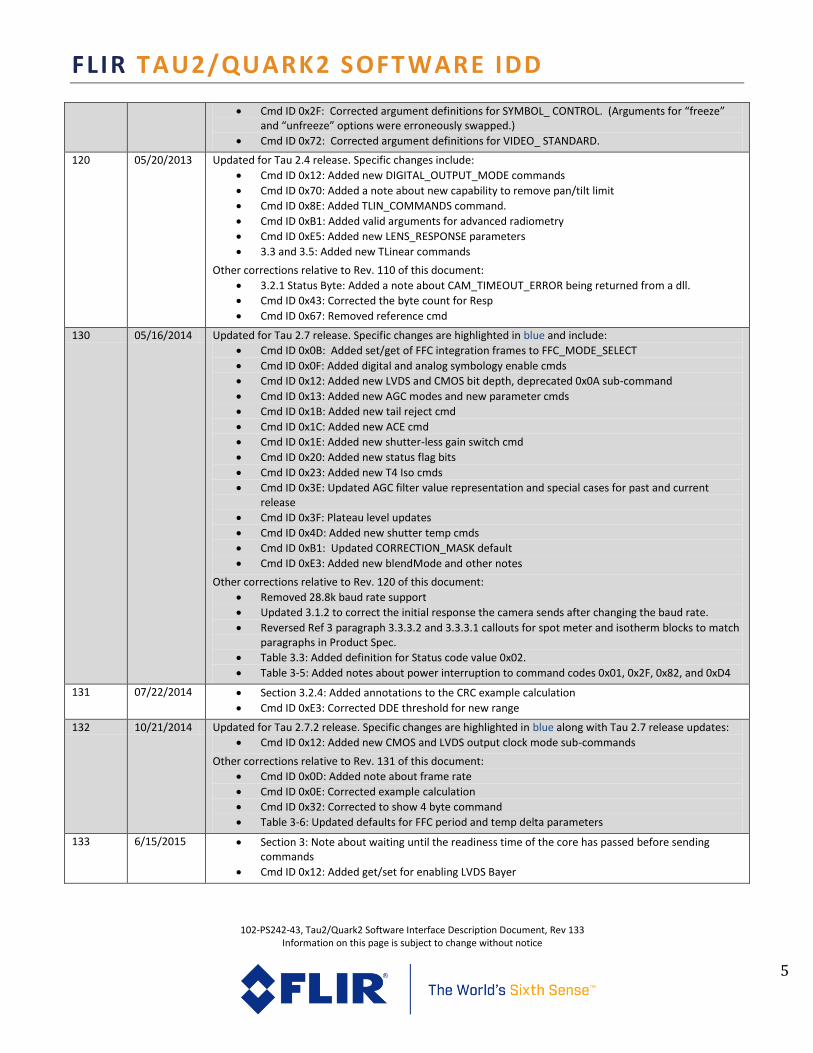
120 05/20/2013 Updated for Tau 2.4 release. Specific changes include:
Cmd ID 0x12: Added new DIGITAL_OUTPUT_MODE commands
Cmd ID 0x70: Added a note about new capability to remove pan/tilt limit
Cmd ID 0x8E: Added TLIN_COMMANDS command.
Cmd ID 0xB1: Added valid arguments for advanced radiometry
Cmd ID 0xE5: Added new LENS_RESPONSE parameters
3.3 and 3.5: Added new TLinear commands
Other corrections relative to Rev. 110 of this document:
3.2.1 Status Byte: Added a note about CAM_TIMEOUT_ERROR being returned from a dll.
Cmd ID 0x43: Corrected the byte count for Resp
Cmd ID 0x67: Removed reference cmd
130 05/16/2014 Updated for Tau 2.7 release. Specific changes are highlighted in blue and include:
Cmd ID 0x0B: Added set/get of FFC integration frames to FFC_MODE_SELECT
Cmd ID 0x0F: Added digital and analog symbology enable cmds
Cmd ID 0x12: Added new LVDS and CMOS bit depth, deprecated 0x0A sub-command
Cmd ID 0x13: Added new AGC modes and new parameter cmds
Cmd ID 0x1B: Added new tail reject cmd
Cmd ID 0x1C: Added new ACE cmd
Cmd ID 0x1E: Added new shutter-less gain switch cmd
Cmd ID 0x20: Added new status flag bits
Cmd ID 0x23: Added new T4 Iso cmds
Cmd ID 0x3E: Updated AGC filter value representation and special cases for past and current release
Cmd ID 0x3F: Plateau level updates
Cmd ID 0x4D: Added new shutter temp cmds
Cmd ID 0xB1: Updated CORRECTION_MASK default
Cmd ID 0xE3: Added new blendMode and other notes
Other corrections relative to Rev. 120 of this document:
Removed 28.8k baud rate support
Updated 3.1.2 to correct the initial response the camera sends after changing the baud rate.
Reversed Ref 3 paragraph 3.3.3.2 and 3.3.3.1 callouts for spot meter and isotherm blocks to match paragraphs in Product Spec.
Table 3.3: Added definition for Status code value 0x02.
Table 3-5: Added notes about power interruption to command codes 0x01, 0x2F, 0x82, and 0xD4
131 07/22/2014 Section 3.2.4: Added annotations to the CRC example calculation
Cmd ID 0xE3: Corrected DDE threshold for new range
132 10/21/2014 Updated for Tau 2.7.2 release. Specific changes are highlighted in blue along with Tau 2.7 release updates:
Cmd ID 0x12: Added new CMOS and LVDS output clock mode sub-commands
Other corrections relative to Rev. 131 of this document:
Cmd ID 0x0D: Added note about frame rate
Cmd ID 0x0E: Corrected example calculation
Cmd ID 0x32: Corrected to show 4 byte command
Table 3-6: Updated defaults for FFC period and temp delta parameters
133 6/15/2015 Section 3: Note about waiting until the readiness time of the core has passed before sending commands
Cmd ID 0x12: Added get/set for enabling LVDS Bayer

FLIR TAU2/QUARK2 SOFT WARE IDD
102-PS242-43, Tau2/Quark2 Software Interface Description Document, Rev 133 Information on this page is subject to change without notice
6
1.2 SCOPE
Tau ™ and Quark are both miniature infrared imaging cores from FLIR Systems®, offered in various configurations. This Interface Description Document (IDD) specifically applies to the Tau 2 configuration of Tau and all configurations of Quark. It defines software interface requirements and commands for both products. Except where noted, all requirements / commands apply to both products, hereafter referred to generically as “the core”. Generally speaking, the Tau 2 serial-communication interface is backwards compatible with Tau 1.X. (That is, an external device designed to communicate with a Tau 1.X core will also be capable of communicating with a Tau 2 core.) However, Tau 2 provides more capabilities and therefore a larger command set. Furthermore both Tau 2 and Quark are intended to be field-upgradeable with feature improvements over time. Consequently this software IDD will be updated to reflect the new commands associated with each upgrade. These are summarized in Table 1. Note: Even though Tau 2 and Tau 1.X share a compatible serial-comm. interface, they are different products with different hardware. It is not possible to upgrade a Tau 1.X core with Tau 2 code, and attempting to do so will cause device failure. Similarly, a Tau 2 cannot be upgraded with Quark code or vice versa.
Table 1: Tau 2 / Quark 1 Release Summary
Release Version
Release Date
New Features / Differences
Tau 2.0 / Quark 1.0
Oct. 2011 Differences shown below are relative to Tau 1.X.
Auto-polarity detection (see 3.2)
New baud rate options (see 3.2.1, and command ID# 0x07 in Table 2-4)
Modification of the DIGITAL_OUTPUT_MODE command (0x12) to support setting CMOS and LVDS bit-width independently.
Modification of the ISOTHERM_THRESHOLDS command (0x23) to support 3-color isotherm. (Tau 1.5 provided a 2-color isotherm only.)
Addition of a SPLASH_CONTROL command (0x31) that provides adjustment of splash-screen timing.
Removal of the PAN_AND_TILT command (0x70). In Tau 2 / Quark, zoom is always relative to the center of the array.
Modification of the VIDEO_STANDARD command (0x72) to include averager-disabled options.
Tau 2.1 Aug. 2012 Differences shown below are relative to Tau 2.0.
New continuous zoom capability. Affected commands: o New bit to VIDEO_MODE (0x0F) allowing fixed zoom bits to be ignored. This enables the
command to be used for enabling or freezing analog video without affecting zoom. o New EZOOM_CONTROL command (0x32) o Change to AGC_ROI (0x4C) o New PAN_AND_TILT (0x70) for changing the location of the zoom window within the
field of view
New ability to capture 8-bit snapshots. Affected commands: o New argument in TRANSFER_FRAME (0x82) o New arguments in GET_MEMORY_ADDRESS (0xD6)
New spot-meter capability (not available on all configurations). Affects GET_SPOT_METER_DATA

FLIR TAU2/QUARK2 SOFT WARE IDD
102-PS242-43, Tau2/Quark2 Software Interface Description Document, Rev 133 Information on this page is subject to change without notice
7
(0x43)
Addition of housing temp, accelerometer data, and overtemp status in the READ_SENSOR command (see command ID 0x20)
Tau 2.4 May 2013 Differences shown below are relative to Tau 2.1.
Continuous zoom capability for 8-bit digital output (SW selectable). New argument in DIGITAL_OUTPUT_MODE (0x12)
Colorization capability for 8-bit digital output (SW selectable). New argument in DIGITAL_OUTPUT_MODE (0x12)
New TLinear capability (not available on all configurations). New command TLIN_COMMANDS (0x8E)
New external scene parameters for improved radiometric accuracy. New arguments LENS_RESPONSE_PARAMS (0xE5)
Tau 2.7 May 2014 Differences shown below are relative to Tau 2.4. (Any text shown in blue font in this document represents a difference relative to Tau 2.4.)
New AGC/DDE including new modes and features. New arguments and sub-commands in AGC_TYPE (0x13), for information-based algorithms and smart scene optimization (SSO). New commands TAIL_SIZE (0x1B) and ACE_CORRECT (0x1C) and other legacy DDE and AGC commands updated
Digital colorization output modes including 8bit or 16bit YCbCr in the CMOS output. New arguments in DIGITAL_OUTPUT_MODE (0x12)
Shutter-less radiometry features. New sub-commands in LENS_NUMBER (0x1E) and SHUTTER_TEMP (0x4D) commands
Symbols now user selectable for analog and digital outputs. New sub-commands in VIDEO_MODE (0x0F)
FFC frames now user selectable. New sub-command in FFC_MODE_SELECT (0x0B)
New Status bits for camera operations. New bits in READ_SENSOR (0x20)
2 REFERENCES The following documents form a part of this specification to the extent specified herein.
2.1 FLIR WEBSITE / CONTACT INFORMATION
In multiple locations throughout this document, FLIR’s Tau / Quark website is referenced as a source of additional information. This websites can be accessed via the following URL:
www.flir.com/cvs/cores/uncooled/products/tau/
http://www.flir.com/cvs/cores/uncooled/products/quark/ A rich knowledge base that provides answer to frequently asked questions can be accessed via:
http://www.flir.com/cvs/cores/knowledgebase/
Additionally, FLIR’s Applications Engineering Department is referenced as a resource for obtaining additional help or information. The department can be accessed via the following phone number: +1-
FLIR TAU2/QUARK2 SOFT WARE IDD
102-PS242-43, Tau2/Quark2 Software Interface Description Document, Rev 133 Information on this page is subject to change without notice
8
805-964-9797 (or toll-free within the United States at 888-747-FLIR (888-747-3547).) Email requests can be addressed to [email protected].
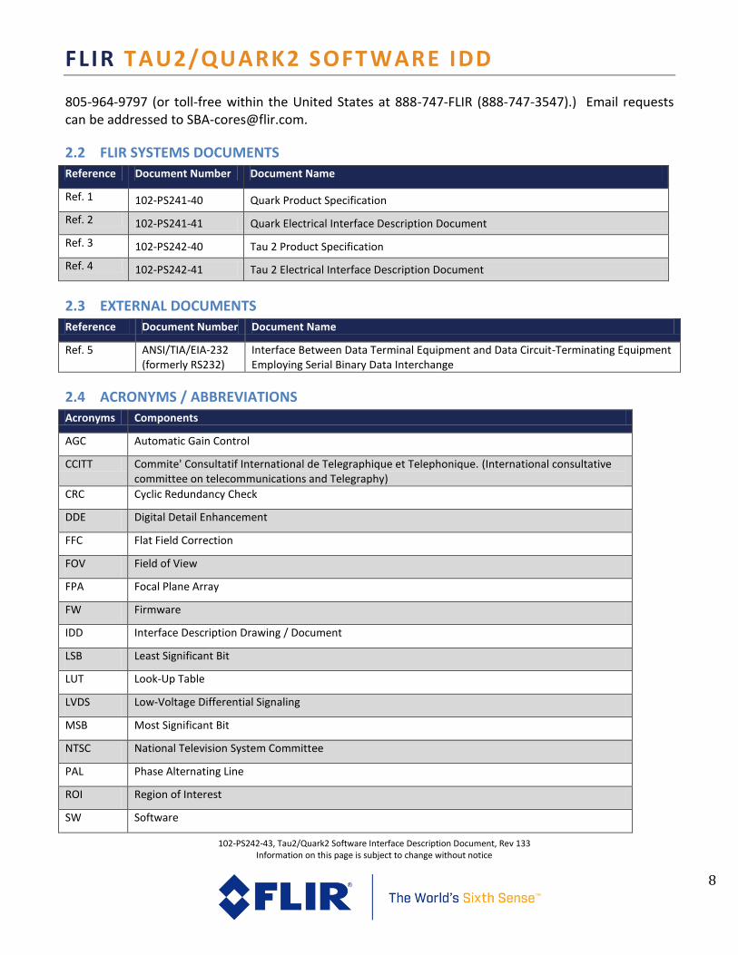
2.2 FLIR SYSTEMS DOCUMENTS
Reference Document Number Document Name
Ref. 1 102-PS241-40 Quark Product Specification
Ref. 2 102-PS241-41 Quark Electrical Interface Description Document
Ref. 3 102-PS242-40 Tau 2 Product Specification
Ref. 4 102-PS242-41 Tau 2 Electrical Interface Description Document
2.3 EXTERNAL DOCUMENTS
Reference Document Number Document Name
Ref. 5 ANSI/TIA/EIA-232 (formerly RS232)
Interface Between Data Terminal Equipment and Data Circuit-Terminating Equipment Employing Serial Binary Data Interchange
2.4 ACRONYMS / ABBREVIATIONS
Acronyms Components
AGC Automatic Gain Control
CCITT Commite' Consultatif International de Telegraphique et Telephonique. (International consultative committee on telecommunications and Telegraphy)
CRC Cyclic Redundancy Check
DDE Digital Detail Enhancement
FFC Flat Field Correction
FOV Field of View
FPA Focal Plane Array
FW Firmware
IDD Interface Description Drawing / Document
LSB Least Significant Bit
LUT Look-Up Table
LVDS Low-Voltage Differential Signaling
MSB Most Significant Bit
NTSC National Television System Committee
PAL Phase Alternating Line
ROI Region of Interest
SW Software
FLIR TAU2/QUARK2 SOFT WARE IDD
102-PS242-43, Tau2/Quark2 Software Interface Description Document, Rev 133 Information on this page is subject to change without notice
9
TBD To Be Determined
XP eXPansion
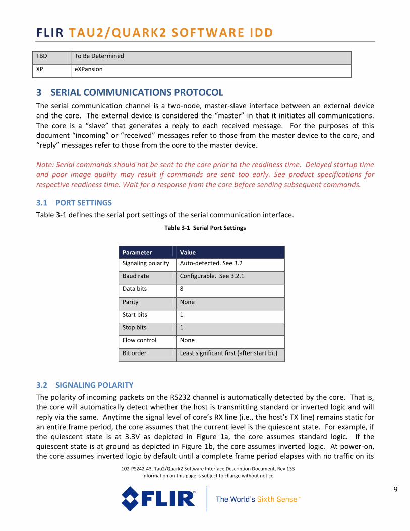
3 SERIAL COMMUNICATIONS PROTOCOL The serial communication channel is a two-node, master-slave interface between an external device and the core. The external device is considered the “master” in that it initiates all communications. The core is a “slave” that generates a reply to each received message. For the purposes of this document “incoming” or “received” messages refer to those from the master device to the core, and “reply” messages refer to those from the core to the master device. Note: Serial commands should not be sent to the core prior to the readiness time. Delayed startup time and poor image quality may result if commands are sent too early. See product specifications for respective readiness time. Wait for a response from the core before sending subsequent commands.
3.1 PORT SETTINGS
Table 3-1 defines the serial port settings of the serial communication interface.
Table 3-1 Serial Port Settings
Parameter Value
Signaling polarity Auto-detected. See 3.2
Baud rate Configurable. See 3.2.1
Data bits 8
Parity None
Start bits 1
Stop bits 1
Flow control None
Bit order Least significant first (after start bit)
3.2 SIGNALING POLARITY
The polarity of incoming packets on the RS232 channel is automatically detected by the core. That is, the core will automatically detect whether the host is transmitting standard or inverted logic and will reply via the same. Anytime the signal level of core’s RX line (i.e., the host’s TX line) remains static for an entire frame period, the core assumes that the current level is the quiescent state. For example, if the quiescent state is at 3.3V as depicted in Figure 1a, the core assumes standard logic. If the quiescent state is at ground as depicted in Figure 1b, the core assumes inverted logic. At power-on, the core assumes inverted logic by default until a complete frame period elapses with no traffic on its

FLIR TAU2/QUARK2 SOFT WARE IDD
102-PS242-43, Tau2/Quark2 Software Interface Description Document, Rev 133 Information on this page is subject to change without notice
10
RX line. Note that auto-polarity detection is always active and therefore signal polarity can be switched dynamically in the middle of a power cycle (though this is not expected to occur in practice).
(a) Standard Logic
(b) Inverted Logic
Figure 1: Example of Standard and Inverted Comm. Traffic
3.2.1 BAUD RATE
The baud rate of the serial comm. channel is configurable to any of the following:
1. Auto-baud (as described below)
2. 9.6k
3. 19.2k
4. 57.6k
5. 115.2k
6. 460.8k
7. 921.6k
Note: Baud rate tolerance to incoming messages is +/- 3%. Outgoing messages are to within +/-1%.
The baud rate is configured via the BAUD_RATE command (0x07) and capable of being stored as a power-on default via the SET_DEFAULTS command (0x01). The BAUD_RATE command must be sent at
1stop
start 0 1 0 10 01(idle state)
1stop
start 0 1 0 10 01(idle state)

FLIR TAU2/QUARK2 SOFT WARE IDD
102-PS242-43, Tau2/Quark2 Software Interface Description Document, Rev 133 Information on this page is subject to change without notice
11
the current baud rate, and the core replies to the command at the original rate. All subsequent commands must then be sent at the newly specified rate and all responses will be at the newly specified rate. For example, if the power-on default for a particular core is 460.8k and a new baud rate of 9.6k is desired, the BAUD_RATE command specifying a change to 9.6k must be sent at 460.8k. The core will reply with an acknowledgement at 460.8k. All future commands on the current power cycle must then be sent at 9.6k baud. At the next power up, the core will return to its power-on default, 460.8k, unless 9.6k was established as the new power-on default by having sent the SET_DEFAULTS command after sending the BAUD_RATE command. Note: If the host is ignorant of the current baud rate setting, it must attempt communication at each baud rate until receiving a valid response. Caution should be exercised when storing a new baud rate as power-on default unless the host is capable of cycling through all possible baud rates. When auto-baud is the current baud-rate setting, the core attempts to detect baud rate from the first message received via the following process:
The elapsed time between the first 6 edges is measured on the RX line (from rise to fall or fall to rise). If the shortest of the 5 elapsed-time periods is between 0.860 usec and 1.302 usec (that is, (921.6 kHz)-1 +20%), the core sets its baud rate to 921.6k. If the shortest period is between 13.889 usec and 20.833 usec (that is, (57.6 kHz)-1 +20%), the core sets its baud rate to 57.6k. Otherwise the auto-detection process starts over again. Figure 2 illustrates the process for a transmitted byte 0x6E, which includes 6 edges and happens to be the first byte of every valid command to the core (see 3.3). Either the period marked #3 or that marked #5 in the figure will be identified as the shortest transition and therefore used to select baud rate.
Note 1: Glitches on the receive line might possibly result in an erroneous detection.
Note 2: The receive logic defaults to 57.6k (i.e., data are sampled at 57.6k beginning with the first start bit). If data is sent at 921.6k, it will be incorrectly sampled until the auto-baud detection process has locked onto the correct baud rate. Consequently, a core in auto-baud will only generate a valid reply to the first message sent by the host if that message is sent at 57.6k. A message sent at 921.6k will establish the faster baud rate but will not generate a valid reply. (The second message sent at 921.6k will be the first that generates a valid reply.) For that reason, it is recommended to send a No Op command (0x00) as the first message when operating in auto-baud mode.
Note 3: The auto-baud detection only occurs once per power cycle; all communications thereafter must be at the same rate.

FLIR TAU2/QUARK2 SOFT WARE IDD
102-PS242-43, Tau2/Quark2 Software Interface Description Document, Rev 133 Information on this page is subject to change without notice
12
Figure 2: Illustration of Edges Used in Auto-Baud Detection Algorithm
3.3 PACKET PROTOCOL
All incoming and reply messages shall adhere to the packet protocol defined in Table 3-2 and the subparagraphs that follow.
Table 3-2 Packet Protocol
Byte # Upper Byte Comments
1 Process Code Set to 0x6E on all valid incoming and reply messages
2 Status See 3.3.1
3 Reserved
4 Function See 3.3.2
5 Byte Count (MSB) See 3.3.3
6 Byte Count (LSB)
7 CRC1 (MSB) See 0
8 CRC1 (LSB)
N Argument See 3.3.5
N+1 CRC2 (MSB) See 0
N+2 CRC2 (LSB)
3.3.1 STATUS BYTE
The second byte of each incoming packet is ignored. For all reply messages, the core sets the second byte as shown in Table 3-3 to indicate status of the previous incoming message packet. The decoding of the incoming message is as follows:
1 stop
start 1 1 0 1 1 0 0
1 3 4 5 2

FLIR TAU2/QUARK2 SOFT WARE IDD
102-PS242-43, Tau2/Quark2 Software Interface Description Document, Rev 133 Information on this page is subject to change without notice
13
1) The byte-count bytes are read to determine the expected length of the packet. If the incoming packet duration exceeds a timeout period (nominally 100 msec), CAM_TIMEOUT_ERROR is reported (status byte = 0x07). Note: Camera SW does not respond with a 0x07 timeout error, but the UL3-RS232.dll used in many applications does provide this message status response.
2) Once the full packet has been received, the CRC bytes are checked first (see 0). If either is incorrect, CAM_CHECKSUM_ERROR is reported (status byte = 0x04).
3) The process-code byte is then checked; if it is not equal to 0x6E, CAM_UNDEFINED_PROCESS_ERROR is returned (status byte = 0x05).
4) The function code is then checked, and if it is invalid (i.e., not one of the codes shown in Table 3-5), CAM_UNDEFINED_FUNCTION_ERROR is returned (status byte = 0x06). CAM_FEATURE_NOT_ENABLED (status byte = 0x0A) is also a possible return if the function code is not supported by the particular configuration (e.g., the command is supported in some configurations of the core, just not the particular configuration receiving the command).
5) The packet length is then checked. If the length is invalid for the function code, CAM_BYTE_COUNT_ERROR is returned (status byte = 0x09).
6) For some function codes, the range of the argument is limited. In those cases, the argument is checked, and CAM_RANGE_ERROR is returned if it is invalid (status byte = 0x03). Note: Any reply packet reporting an error will have no data bytes (i.e., byte count = 0).
Table 3-3 Status Byte Definition
Status Byte Value (hex) Definition Description
0x00 CAM_OK Message received
0x02 CAM _NOT_READY Not able to process a command at this time
0x03 CAM _RANGE_ERROR Argument out of range
0x04 CAM _CHECKSUM_ERROR Header or message-body checksum error
0x05 CAM _UNDEFINED_PROCESS_ERROR Unknown process code
0x06 CAM _UNDEFINED_FUNCTION_ERROR Unknown function code
0x07 CAM _TIMEOUT_ERROR Timeout executing serial command
0x09 CAM _BYTE_COUNT_ERROR Byte count incorrect for the function code
0x0A CAM _FEATURE_NOT_ENABLED Function code not enabled in the current configuration
3.3.2 FUNCTION BYTE
The function-code byte is used to specify the function of an incoming message. For all reply messages, the camera will echo back the function-code byte. A list of all valid Tau 2 / Quark commands is shown
FLIR TAU2/QUARK2 SOFT WARE IDD
102-PS242-43, Tau2/Quark2 Software Interface Description Document, Rev 133 Information on this page is subject to change without notice
14
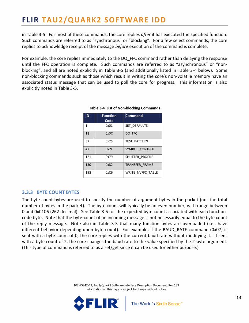
in Table 3-5. For most of these commands, the core replies after it has executed the specified function. Such commands are referred to as “synchronous” or “blocking”. For a few select commands, the core replies to acknowledge receipt of the message before execution of the command is complete. For example, the core replies immediately to the DO_FFC command rather than delaying the response until the FFC operation is complete. Such commands are referred to as “asynchronous” or “non-blocking”, and all are noted explicitly in Table 3-5 (and additionally listed in Table 3-4 below). Some non-blocking commands such as those which result in writing the core’s non-volatile memory have an associated status message that can be used to poll the core for progress. This information is also explicitly noted in Table 3-5.
Table 3-4 List of Non-blocking Commands
ID Function Code
Command
1 0x01 SET_DEFAULTS
12 0x0C DO_FFC
37 0x25 TEST_PATTERN
47 0x2F SYMBOL_CONTROL
121 0x79 SHUTTER_PROFILE
130 0x82 TRANSFER_FRAME
198 0xC6 WRITE_NVFFC_TABLE
3.3.3 BYTE COUNT BYTES
The byte-count bytes are used to specify the number of argument bytes in the packet (not the total number of bytes in the packet). The byte count will typically be an even number, with range between 0 and 0x0106 (262 decimal). See Table 3-5 for the expected byte count associated with each function-code byte. Note that the byte-count of an incoming message is not necessarily equal to the byte count of the reply message. Note also in Table 3-5 that many function bytes are overloaded (i.e., have different behavior depending upon byte-count). For example, if the BAUD_RATE command (0x07) is sent with a byte count of 0, the core replies with the current baud rate without modifying it. If sent with a byte count of 2, the core changes the baud rate to the value specified by the 2-byte argument. (This type of command is referred to as a set/get since it can be used for either purpose.)

FLIR TAU2/QUARK2 SOFT WARE IDD
102-PS242-43, Tau2/Quark2 Software Interface Description Document, Rev 133 Information on this page is subject to change without notice
15
3.3.4 CRC BYTES
On all incoming and outgoing messages, two cyclical redundancy checks (CRCs) are calculated using CCITT-16 initialized to 0. (Polynomial = x16 + x12 + x5 + 1.) CRC1 is calculated using only the first 6 bytes of the packet. CRC2 is calculated using all previous bytes in the packet (i.e. bytes 0 through N). Below is an example showing a CRC calculation for the single byte. The example data is 0x6E (01101110 binary). The polynomial is 10001000000100001 (binary)
The basic procedure is to line up the most significant bits of the padded data and the polynomial as shown below. If the data bit directly above the most significant bit (MSb) of the polynomial is a one, then the data for the next step is the XOR of the current data and the polynomial. If that data bit is a zero, then the input data is carried on to the next step unchanged. The polynomial is then shifted one bit to the right, and the above process is repeated until the polynomial has been shifted so that its least significant bit is lined up with that of the data word. 011011100000000000000000 [Right-pad the data with 16 zeros and check the bit above the MSb of the polynomial] ⊕10001000000100001 -------------------------- 011011100000000000000000 [A zero was found in the previous data word, so the data is simply copied this time] ⊕010001000000100001 ---------------------------- 001010100000100001000000 [A one was found in the previous data word, so this new data is the XOR of the data and polynomial] ⊕0010001000000100001 ----------------------------- 000010000000110001100000 [A one was found in the previous data word, so the XOR is done again] ⊕00010001000000100001 ------------------------------- 000010000000110001100000 [A zero was found in the previous data word, so the data is simply copied again] ⊕000010001000000100001 --------------------------------- 000000001000110101101000 [A one was found in the previous data word, so the XOR is done again] ⊕0000010001000000100001 ---------------------------------- 000000001000110101101000 [A zero was found in the previous data word, so the data is simply copied again] ⊕00000010001000000100001 ----------------------------------- 000000001000110101101000 [A zero was found in the previous data word, so the data is simply copied again] ⊕000000010001000000100001 [This is as far as the polynomial can be shifted, so this will be the last step] ------------------------------------- 000000001000110101101000 [A zero was found in the previous data word, so the data is simply copied again] = 0x8D68
3.3.5 ARGUMENT BYTES
The argument bytes (also called data bytes) are used to encode the argument of a message packet. The number of argument bytes is typically an even number. See Table 3-5 for the argument definition for each message. Two’s-complement numbering is used for all signed values. Big-endian ordering is employed: Byte 0, Byte 1, Byte 2, etc.
FLIR TAU2/QUARK2 SOFTWARE IDD
102-PS242-43, Tau2/Quark2 Software Interface Description Document, Rev 133 Information on this page is subject to change without notice
16
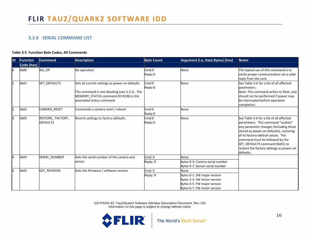
3.3.6 SERIAL COMMAND LIST
Table 3-5 Function Byte Codes, All Commands
ID Function Code (hex)
Command Description Byte Count Argument (i.e, Data Bytes) (hex) Notes
0 0x00 NO_OP No operation Cmd:0 Reply:0
None The typical use of this command is to verify proper communication via a valid reply from the core.
1 0x01 SET_DEFAULTS Sets all current settings as power-on defaults This command is non-blocking (see 3.3.2). The MEMORY_STATUS command (ID #196) is the associated status command.
Cmd:0 Reply:0
None See Table 3-6 for a list of all affected parameters. Note: This command writes to flash, and should not be performed if power may be interrupted before operation completion.
2 0x02 CAMERA_RESET Commands a camera reset / reboot Cmd:0 Reply:0
None
3 0x03 RESTORE_ FACTORY_ DEFAULTS
Reverts settings to factory defaults.
Cmd:0 Reply:0
None See Table 3-6 for a list of all affected parameters. This command “undoes” any parameter changes (including those stored as power-on defaults), restoring all to factory-default values. This command must be followed by the SET_DEFAULTS command (0x01) to restore the factory settings as power-on defaults.
4 0x04 SERIAL_NUMBER Gets the serial number of the camera and sensor
Cmd: 0 None
Reply: 8 Bytes 0-3: Camera serial number Bytes 4-7: Sensor serial number
5 0x05 GET_REVISION Gets the firmware / software version Cmd: 0 None
Reply: 8 Bytes 0-1: SW major version Bytes 2-3: SW minor version Bytes 4-5: FW major version Bytes 6-7: FW minor version

FLIR TAU2/QUARK2 SOFTWARE IDD
102-PS242-43, Tau2/Quark2 Software Interface Description Document, Rev 133 Information on this page is subject to change without notice
17
Table 3-5 Function Byte Codes, All Commands
ID Function Code (hex)
Command Description Byte Count Argument (i.e, Data Bytes) (hex) Notes
7 0x07 BAUD_RATE Gets or sets the baud rate of the serial comm. channel
Get Cmd: 0 (Reply: 2)
None See 3.2.1 for further explanation.
Set Cmd: 2 & Reply: 2
0x0000: Auto baud 0x0001: 9600 baud 0x0002: 19200 baud 0x0004: 57600 baud 0x0005: 115200 baud 0x0006: 460800 baud 0x0007: 921600 baud
10 0x0A GAIN_MODE Gets or sets the dynamic-range-control mode Get Cmd: 0 (Reply: 2)
None See para. 3.3.2.2 of Ref. 1 / Ref. 3 for definition of each mode.
Set Cmd:2 & Reply: 2
0x0000 = Automatic 0x0001 = Low Gain Only 0x0002 = High Gain Only 0x0003 = Manual
11 0x0B FFC_MODE_ SELECT Gets or sets the Flat Field Correction (FFC) mode or the number of integrated frames during FFC.
Get Cmd: 0 (Reply: 2)
None See para. 3.3.2.1 of Ref. 1 / Ref. 3 for definition of each mode.
Set Cmd:2 & Reply: 2
0x0000 = Manual 0x0001 = Automatic 0x0002 = External
Get: 4 (Reply: 2)
Byte 0-1 (Get): 0x0003 Byte 2-3 (Get): Don’t care Byte 0-1 (Reply): 0x0000 = 4 frames 0x0001 = 8 frames 0x0002 = 16 frames

FLIR TAU2/QUARK2 SOFTWARE IDD
102-PS242-43, Tau2/Quark2 Software Interface Description Document, Rev 133 Information on this page is subject to change without notice
18
Table 3-5 Function Byte Codes, All Commands
ID Function Code (hex)
Command Description Byte Count Argument (i.e, Data Bytes) (hex) Notes
Set: 4 & Reply: 0
Byte 0-1 (Set): 0x0002 Byte 2-3 (Set): 0x0000 = 4 frames 0x0001 = 8 frames 0x0002 = 16 frames
12 0x0C DO_FFC Commands FFC A “short” or “long” FFC can be optionally specified. If sent with no argument, a short FFC is executed. This command is non-blocking (see 3.3.2). There is no associated status command.
Cmd:0 Reply:0
None See para. 3.3.2.1 of Ref. 1 / Ref. 3 for explanation of short FFC and long FFC.
Cmd: 2
0x0000 = short FFC 0x0001 = long FFC
& Reply: 2 0xFFFF

FLIR TAU2/QUARK2 SOFTWARE IDD
102-PS242-43, Tau2/Quark2 Software Interface Description Document, Rev 133 Information on this page is subject to change without notice
19
Table 3-5 Function Byte Codes, All Commands
ID Function Code (hex)
Command Description Byte Count Argument (i.e, Data Bytes) (hex) Notes
13 0x0D FFC_PERIOD Gets or sets the interval (in frames) between automatic FFC; different values are specified for each gain state Note: Frame rate for determining the interval time is dependent on the video standard not the actual frame rate, where NTSC = 30Hz, PAL = 25Hz
Get Cmd: 0 (Reply: 4)
None Range: 0 to 30,000 (frames) An argument value of 0 signals that elapsed time will not be used to trigger FFC. See para. 3.3.2.1 of Ref. 1 / Ref. 3 for explanation of the parameter.
Set Cmd:2 & Reply: 2
FFC interval for current gain state
Set Cmd:4 & Reply: 4
Bytes 0-1: FFC interval, high gain Bytes 2-3: FFC interval, low gain
14 0x0E FFC_TEMP_DELTA Gets or sets the temperature difference used to trigger automatic FFC The specified value is converted to Celsius degrees by dividing by 10 then adding 0.1. For example, a value of 10 corresponds to a delta temperature of 1.1C deg.
Get Cmd: 0 (Reply: 4)
None Range: 0 to 1000 (0.1C to 100.1C degrees) See para. 3.3.2.1 of Ref. 1 / Ref. 3 for explanation of the parameter
Set Cmd:2 & Reply: 2
Temp delta value for current gain state
Set Cmd:4 & Reply: 4
Bytes 0-1: Temp delta, high gain Bytes 2-3: Temp delta, low gain
15 0x0F VIDEO_MODE Gets or sets the video signal mode, enabling analog channel to be enabled/disabled and allowing freeze frame or real-time data. Note: Bits 2, 3, and 4 are valid for selecting 1X, 2X, 4X, or 8X zoom provided that bit 9 is set to 0. When bit 9 is set to 1, bits 2-4 are ignored. Note that the on-screen icons indicating 2X, 4X, and 8X zoom are enabled using the VIDEO_MODE command. The new EZOOM_CONTROL command will not causes on-screen icons to be displayed.
Get Cmd: 0 (Reply: 2)
None See para. 3.1.2.3 and 3.3.2.4 of Ref. 1 / Ref. 3 for definition of each mode.
Set Cmd: 2 & Reply: 2
Video mode: bit 0: 0 = real-time 1 = freeze bit 1: 0 = analog enabled 1 = analog disabled bit 2: 0 = 2X off, 1 = 2X enabled bit 3: 0 = 4X off, 1 = 4X enabled bit 4: 0 = 8X off, 1 = 8X enabled bit 9: 0 = zoom bits valid 1 = zoom bits ignored
Enables and disables symbology overlay in analog video
Get Cmd: 4 (Resp: 2)
Byte 0-1: const_0x0000 Byte 2-3: dontCare
Set Cmd: 4 & Resp: 4
Byte 0-1: const_0x0001 Byte 2-3: analogEnable 0x0000 = disabled 0x0001 = enabled

FLIR TAU2/QUARK2 SOFTWARE IDD
102-PS242-43, Tau2/Quark2 Software Interface Description Document, Rev 133 Information on this page is subject to change without notice
20
Table 3-5 Function Byte Codes, All Commands
ID Function Code (hex)
Command Description Byte Count Argument (i.e, Data Bytes) (hex) Notes
Enables and disables symbology overlay in digital video
Get Cmd: 4 (Resp: 2)
Byte 0-1: const_0x0002 Byte 2-3: dontCare
Note: Digital symbology only applies to the Digital eZoom Mode
enabled/colorized output channels. Set Cmd: 4 & Resp: 4
Byte 0-1: const_0x0003 Byte 2-3: digitalEnable 0x0000 = disabled 0x0001 = enabled
16 0x10 VIDEO_PALETTE Gets or sets the video palette Get Cmd: 0 (Reply: 2)
None Range: 0 to 29 See para. 3.3.2.7 of Ref. 1 / Ref. 3 for explanation of the parameter
Set Cmd: 2 & Reply: 2
Palette number
17 0x11 VIDEO_ ORIENTATION Gets or sets the video orientation Get Cmd: 0 (Reply: 2)
None See para. 3.3.2.3 of Ref. 1 / Ref. 3 for definition of each mode.
Set Cmd: 2 & Reply: 2
0x0000 = Normal 0x0001 = Invert 0x0002 = Revert 0x0003 = Invert + Revert

FLIR TAU2/QUARK2 SOFTWARE IDD
102-PS242-43, Tau2/Quark2 Software Interface Description Document, Rev 133 Information on this page is subject to change without notice
21
Table 3-5 Function Byte Codes, All Commands
ID Function Code (hex)
Command Description Byte Count Argument (i.e, Data Bytes) (hex) Notes
18 0x12 DIGITAL_ OUTPUT_MODE
Gets or sets the digital output channel modes, depending upon byte count and arguments value.
Get Cmd: 0 (Reply: 2)
None See para. 3.1.2.4 of Ref. 1 / Ref. 3 for definition of the various digital output modes. Note: In Tau 1.X, it was not possible to set bit depth of the CMOS and LVDS channels independently. Both had to be set to either 8bit or 14bit mode. For Tau 2, the command has been modified to allow a different bit depth to be specified for each channel.
Set Cmd: 2 & Reply: 2
Common disable (affects both the LVDS and XP channels) 0x0000 = enabled 0x0002 = disabled
Gets the XP Mode Get Cmd: 2 Byte 0: 0x02 Byte 1: don’t care
Reply: 2 Bytes 0-1: XP Mode 0x0000 = disabled 0x0001 = BT656 0x0002 = CMOS 14-bit w/ 1 discrete 0x0003 = CMOS 8-bit w/ 8 discretes 0x0004 = CMOS 16-bit
Sets the XP Mode Set Cmd: 2 & Reply: 2
Byte 0: 0x03 Byte 1: 0x00 = disabled 0x01 = BT656 0x02 = CMOS 14-bit w/ 1 discrete 0x03 = CMOS 8-bit w/ 8 discretes 0x04 = CMOS 16-bit
Gets the LVDS Mode Get Cmd: 2 Byte 0: 0x04 Byte 1: don’t care
Reply: 2 Bytes 0-1: LVDS enable 0x0000 = disabled 0x0001 = enabled
Set the LVDS Mode Set Cmd: 2 & Reply: 2
Byte 0: 0x05 Byte 1: 0x00 = disabled 0x01 = enabled

FLIR TAU2/QUARK2 SOFTWARE IDD
102-PS242-43, Tau2/Quark2 Software Interface Description Document, Rev 133 Information on this page is subject to change without notice
22
Table 3-5 Function Byte Codes, All Commands
ID Function Code (hex)
Command Description Byte Count Argument (i.e, Data Bytes) (hex) Notes
Sets the CMOS mode Bit Depth (8 or 14bit) Set Cmd: 2 & Reply: 2
Byte 0: 0x06 Byte 1: 0x00 = 14bit pre-AGC 0x01 = 8bit post-AGC/pre-colorize 0x02 = 8bit Bayer encoded 0x03 = 16bit YCbCr 0x04 = 8bit 2x Clock YCbCr
YCbCr should be used instead of Bayer whenever possible. Bayer encoding has image artifacts when working on single pixel colorization.
Sets the LVDS mode Bit Depth (8 or 14bit) Set Cmd: 2 & Reply: 2
Byte 0: 0x07 Byte 1: 0x00 = 14bit 0x01 = 8bit post-AGC/pre-colorize 0x02 = 8bit Bayer encoded
Gets the CMOS mode Bit Depth (8 or 14bit) Get Cmd: 2 Byte 0: 0x08 Byte 1: don’t care
Reply: 2 0x0000 = 14bit 0x0001 = 8bit post-AGC/pre-colorize 0x0002 = 8bit Bayer encoded 0x0003 = 16bit YCbCr 0x0004 = 8bit 2x Clock YCbCr
Gets the LVDS mode Bit Depth (8 or 14bit) Get Cmd: 2 Byte 0: 0x09 Byte 1: don’t care
Reply: 2 0x0000 = 14bit 0x0001 = 8bit post-AGC/pre-colorize 0x0002 = 8bit Bayer encoded
Sets the Digital Color Mode for 8-bit Digital Data Set cmd: 2 & Resp: 2
Byte 0: 0x0A Byte 1: Digital Color Enable 0x00 = Disable 0x01 = Enable
This command has been deprecated for Tau 2.7 and later releases. Digital color may be enabled and the mode selected with the single command above for the CMOS and/or LVDS output. See para. 3.3.2.7 of Ref. 3 for explanation of these digital output modes.
Gets the Digital Color Mode for 8-bit Digital Data
Get cmd: 2 Byte 0: 0x0B Byte 1: don’t care
Resp:2 Bytes 0-1: Digital Color Enable 0x0000 = Disable 0x0001 = Enable

FLIR TAU2/QUARK2 SOFTWARE IDD
102-PS242-43, Tau2/Quark2 Software Interface Description Document, Rev 133 Information on this page is subject to change without notice
23
Table 3-5 Function Byte Codes, All Commands
ID Function Code (hex)
Command Description Byte Count Argument (i.e, Data Bytes) (hex) Notes
Sets the Digital eZoom Mode for 8-bit Digital Data
Set cmd/resp: 2 Byte 0: 0x0E Byte 1: Digital Out Select Enable 0x00 = Disable 0x01 = Enable
0=Disable, 1=Enable Note: Enables/Disables eZoom in the 8-bit digital path. See para. 3.2.1, 3.2.2, and 3.3.2.4 of Ref. 3 for explanation and details regarding this feature. Gets the Digital eZoom Mode for 8-bit Digital
Data Get cmd: 2
Bytes 0: 0x0F Byte 1: don’t care
Resp:2 Bytes 0-1: Digital Out Select Enable 0x0000 = Disable 0x0001 = Enable
Sets Bayer Encoding Order for 8-bit Digital Data Set cmd: 2 & Resp: 2
Byte 0: 0x14 Byte 1: Bayer Order 0x00=GR, 0x01=GB, 0x02=BG, 0x03=RG
Bayer order refers to the pattern applied starting with top-left to top-right pixel in the RGB filter. See para. 3.3.2.7 of Ref. 3 for details regarding Bayer encoding. Gets Bayer Encoding Order for 8-bit Digital Data Get cmd: 2 Bytes 0-1: 0x1500
Resp:2 Bytes 0-1: Bayer Order 0x0000=GR, 0x0001=GB, 0x0002=BG, 0x0003=RG
Gets the CMOS output clock mode Get cmd: 2 Bytes 0-1: 0x1C00 The CMOS clock polarity can be altered with this command. The default clock mode is “normal”. See section 3.1.4.2 of Ref. 4 for details regarding the CMOS output timing.
Resp:2 Bytes 0-1: Clock Mode 0x0000=normal 0x0001=invert
Sets the CMOS output clock mode Set cmd: 2 & Resp: 2
Byte 0: 0x1D Byte 1: 0x00=normal 0x01=invert
Gets the LVDS output clock mode Get cmd: 2 Bytes 0-1: 0x2000 The LVDS clock polarity can be altered with this command. The default clock mode is “normal”. See section 3.1.4.3 of Ref. 4 for details regarding the LVDS output timing.
Resp:2 Bytes 0-1: Clock Mode 0x0000=normal 0x0001=invert
Sets the LVDS output clock mode Set cmd: 2 & Resp: 2
Byte 0: 0x21 Byte 1: 0x00=normal 0x01=invert
FLIR TAU2/QUARK2 SOFTWARE IDD
102-PS242-43, Tau2/Quark2 Software Interface Description Document, Rev 133 Information on this page is subject to change without notice
24
Table 3-5 Function Byte Codes, All Commands
ID Function Code (hex)
Command Description Byte Count Argument (i.e, Data Bytes) (hex) Notes
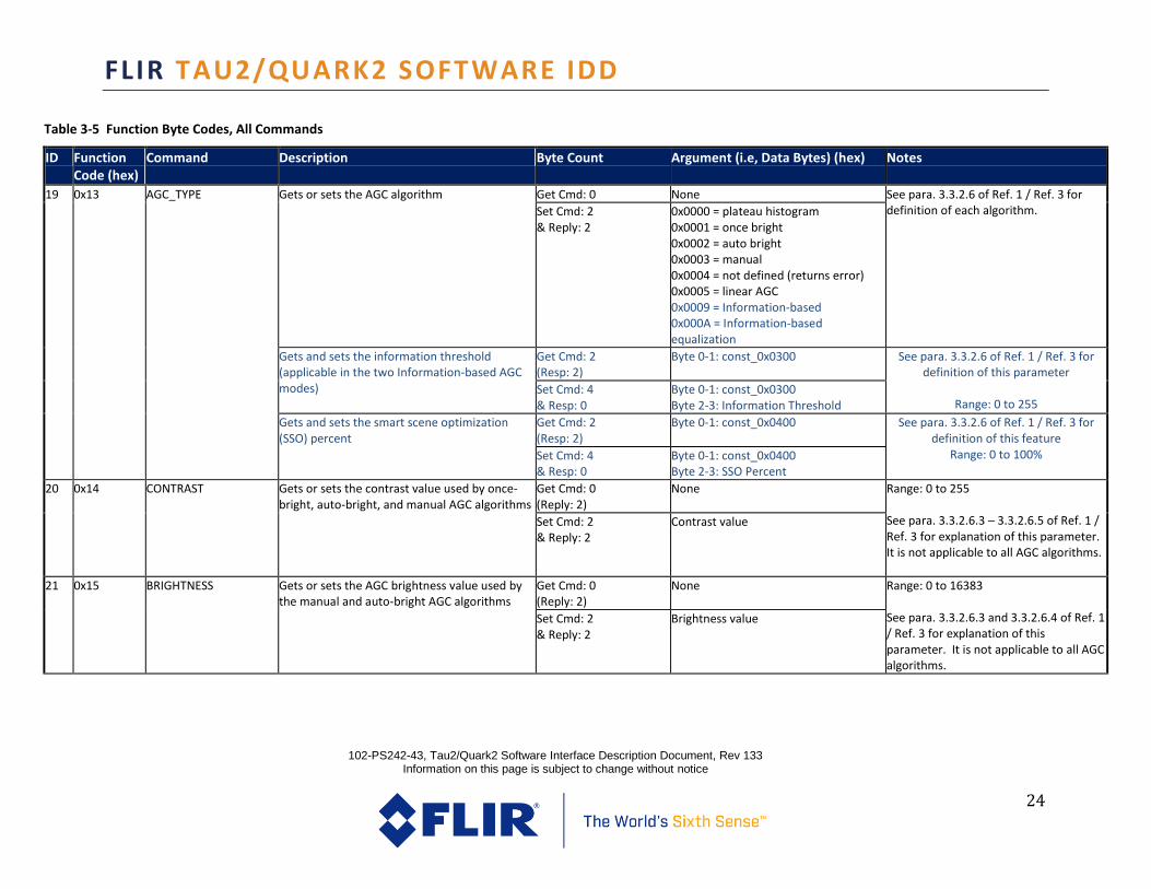
19 0x13 AGC_TYPE Gets or sets the AGC algorithm Get Cmd: 0 None See para. 3.3.2.6 of Ref. 1 / Ref. 3 for definition of each algorithm.
Set Cmd: 2 & Reply: 2
0x0000 = plateau histogram 0x0001 = once bright 0x0002 = auto bright 0x0003 = manual 0x0004 = not defined (returns error) 0x0005 = linear AGC 0x0009 = Information-based 0x000A = Information-based equalization
Gets and sets the information threshold (applicable in the two Information-based AGC modes)
Get Cmd: 2 (Resp: 2)
Byte 0-1: const_0x0300 See para. 3.3.2.6 of Ref. 1 / Ref. 3 for definition of this parameter
Range: 0 to 255
Set Cmd: 4 & Resp: 0
Byte 0-1: const_0x0300 Byte 2-3: Information Threshold
Gets and sets the smart scene optimization (SSO) percent
Get Cmd: 2 (Resp: 2)
Byte 0-1: const_0x0400 See para. 3.3.2.6 of Ref. 1 / Ref. 3 for definition of this feature
Range: 0 to 100%
Set Cmd: 4 & Resp: 0
Byte 0-1: const_0x0400 Byte 2-3: SSO Percent
20 0x14 CONTRAST Gets or sets the contrast value used by once-bright, auto-bright, and manual AGC algorithms
Get Cmd: 0 (Reply: 2)
None Range: 0 to 255 See para. 3.3.2.6.3 – 3.3.2.6.5 of Ref. 1 / Ref. 3 for explanation of this parameter. It is not applicable to all AGC algorithms.
Set Cmd: 2 & Reply: 2
Contrast value
21 0x15 BRIGHTNESS Gets or sets the AGC brightness value used by the manual and auto-bright AGC algorithms
Get Cmd: 0 (Reply: 2)
None Range: 0 to 16383 See para. 3.3.2.6.3 and 3.3.2.6.4 of Ref. 1 / Ref. 3 for explanation of this parameter. It is not applicable to all AGC algorithms.
Set Cmd: 2 & Reply: 2
Brightness value

FLIR TAU2/QUARK2 SOFTWARE IDD
102-PS242-43, Tau2/Quark2 Software Interface Description Document, Rev 133 Information on this page is subject to change without notice
25
Table 3-5 Function Byte Codes, All Commands
ID Function Code (hex)
Command Description Byte Count Argument (i.e, Data Bytes) (hex) Notes
24 0x18 BRIGHTNESS_BIAS Gets or sets the brightness bias value used by the once-bright AGC algorithm
Get Cmd: 0 (Reply: 2)
None Range: -16384 to 16383 See para. 3.3.2.6.5 of Ref. 1 / Ref. 3 for explanation of this parameter. It is not applicable to all AGC algorithms.
Set Cmd: 2 & Reply: 2
Brightness bias value

FLIR TAU2/QUARK2 SOFTWARE IDD
102-PS242-43, Tau2/Quark2 Software Interface Description Document, Rev 133 Information on this page is subject to change without notice
26
Table 3-5 Function Byte Codes, All Commands
ID Function Code (hex)
Command Description Byte Count Argument (i.e, Data Bytes) (hex) Notes
27 0x1B TAIL_SIZE Gets or sets the tail rejection percentage for AGC
Get Cmd: 0 (Resp: 2)
Tail Size See para. 3.3.2.6 of Ref. 1 / Ref. 3 for definition of this parameter
Range: 0.0 to 20.0% Format: Percent x10
Set Cmd: 2 & Resp: 2
28 0x1C ACE_CORRECT Gets or sets the Active Contrast Enhancement (ACE) Correction for AGC
Get Cmd: 0 (Resp: 2)
ACE Correction See para. 3.3.2.6 of Ref. 1 / Ref. 3 for definition of this parameter
Range: -8 to 8 0 = disabled
Set Cmd: 2 & Resp: 0
30 0x1E LENS_NUMBER Gets or sets the lens number (which affects which correction terms are applied)
Get Cmd: 0 (Reply: 2)
None See para. 3.3.2.10 and 3.3.2.11 of Ref. 3 for the purpose of this command.
Set Cmd: 2 & Reply: 2
0x0000 = lens 0 0x0001 = lens 1
Enables and disables the gain/lens switch feature. With this mode enabled, high and low gain modes are mapped to lens 0 and lens1 for shutter-less gain mode switching.
Get Cmd: 2 (Resp: 2)
Bytes 0-1: const_0x0200
See 3.3.2.2 of Ref. 1 / Ref. 3 and the FLIR website for the Advanced Radiometry
Application Note for the purpose of this command.
It is recommended that this feature and associated calibration be accessed using
the Camera Controller GUI.
Set Cmd: 4 & Resp: 4
Bytes 0-1: const_0x0001 Bytes 2-3: gainSwitchLensMode 0x0000 = disabled 0x0001 = enabled
Gets or sets the mapping between high and low gain modes to lens numbers.
Get Cmd: 2 (Resp: 2)
Bytes 0-1: const_0x0300 hiGainIndex is the lens number (0 or 1) tied to high gain mode
loGainIndex is the lens number (0 or 1) tied to low gain mode
These indices cannot be set equal (i.e.
only 01 and 10 are valid)
Set Cmd: 4 & Resp: 4
Bytes 0-1: const_0x0002 Bytes 2: hiGainIndex Bytes 3: loGainIndex
31 0x1F SPOT_METER_ MODE Gets or sets the spot-meter mode
Get Cmd: 0 (Reply: 2)
None See para. 3.3.3.2 of Ref. 3 for explanation of this mode.

FLIR TAU2/QUARK2 SOFTWARE IDD
102-PS242-43, Tau2/Quark2 Software Interface Description Document, Rev 133 Information on this page is subject to change without notice
27
Table 3-5 Function Byte Codes, All Commands
ID Function Code (hex)
Command Description Byte Count Argument (i.e, Data Bytes) (hex) Notes
(Returns an error for those configurations which do not support the feature.)
Set Cmd: 2 & Reply: 2
0x0000 = disabled (off) 0x0001 = on, Fahrenheit scale 0x0002 = on, Centigrade scale
32 0x20 READ_SENSOR Gets various data from the core, depending upon argument of incoming message
Cmd: 2 & Reply: 2 Reply: 2
Incoming arg. | Outgoing response 0x0000 | FPA temp in deg. C*10 0x0001 | FPA temp in raw counts 0x0002 – 0009 | unused 0x000A | Housing temp, deg. C x 100 0x000C – 0x0010 | reserved 0x0011 | Status bits:
Bit 0: Overtemp status (set to 1 when operating outside temp range) Bits 2, 7 - 15: Reserved. Bit 3: 0 = normal, 1 = FFC desired Bit 4: 0 = normal, 1 = Gain switch desired Bit 5: 0 = normal, 1 = NUC switch desired Bit 6: 0 = normal, 1 = FFC in progress
See 3.3.4.3 of Ref. 1 / Ref. 3
See 3.3.4.4 of Ref. 1 / Ref. 3 for explanation of the overtemp status. See 3.3.4.5 of Ref. 1/ Ref. 3 for explanation of all other status indicators.
Cmd: 2 0x000B
Reply: 8 Accelerometer data: Bytes 0-1: X-axis (0.01 g) Bytes 2-3: Y-axis (0.01 g) Bytes 4-5: Z-axis (0.01 g) Bytes 6-7: Reserved
33 0x21 EXTERNAL_SYNC Gets or sets external sync mode Get Cmd: 0 (Reply: 2)
None See para. 3.1.2.7 of Ref. 1 / Ref. 3 for definition of each mode.
Set Cmd: 2 & Reply: 2
0x0000 = disabled 0x0001 = slave 0x0002 = master

FLIR TAU2/QUARK2 SOFTWARE IDD
102-PS242-43, Tau2/Quark2 Software Interface Description Document, Rev 133 Information on this page is subject to change without notice
28
Table 3-5 Function Byte Codes, All Commands
ID Function Code (hex)
Command Description Byte Count Argument (i.e, Data Bytes) (hex) Notes
34 0x22 ISOTHERM Gets or sets the isotherm mode (on/off) (Returns an error for those configurations which do not support the feature.)
Get Cmd: 0 (Reply: 2)
None See para. 3.3.3.1 of Ref. 3 for explanation of the feature.
Set Cmd: 2 & Reply: 2
0x0000 = Disabled 0x0001 = Enabled
35 0x23 ISOTHERM_ THRESHOLDS
Gets or sets the isotherm thresholds in percent ( e.g. 97 decimal = 97%) or in deg C (e.g., 97 decimal = 97C). Bit 15 of the lower threshold is used to specify units (0 for percent, 1 for deg C). Percent is relative to a value of 160C when in high-gain mode and 600C when in low-gain mode. For example, a value of 97% equates to 155C in high-gain mode, 582C in low-gain mode. (Returns an error for those configurations which do not support the feature.)
Get Cmd: 0 (Reply: 6)
None Percentage range: 0 – 100 Temperature range -40 to 1000 ºC Thresholds must be in proper order: (Lower <= Middle <= Upper) See para. 3.3.3.1 of Ref. 3 for definition of the thresholds.
Set Cmd: 6 & Reply: 6
Bytes 0 – 1: lower threshold Bytes 2 – 3: middle threshold Bytes 4 – 5: upper threshold Bit 15 of the lower threshold is used to specify units (1 = deg C, 0 = %).
Gets or sets the four isotherm mode (otherwise the three isotherm mode is applied)
Get Cmd: 4 (Resp: 2)
Bytes 0-1: const_0x0002 Bytes 2-3: dontCare
Set Cmd: 4 & Resp: 4
Bytes 0-1: const_0x0003 Bytes 2-3: isoT4Mode
0x0000 = disable 0x0001 = enable
Gets or sets the fourth isotherm (the isotherm saturation threshold)
Get Cmd: 4 (Resp: 2)
Bytes 0-1: const_0x0000 Bytes 2-3: dontCare
Note: The fourth threshold is the saturation threshold, all temperatures above this are mapped to the highest isotherm color
Set Cmd: 4 & Resp: 4
Bytes 0-1: const_0x0001 Bytes 2-3: saturation threshold
Gets or sets all four isotherm thresholds Get Cmd: 4 (Resp: 2)
Bytes 0-1: const_0x0004 Bytes 2-3: dontCare
Percentage range: 0 – 100 Temperature range -40 to 1000 ºC

FLIR TAU2/QUARK2 SOFTWARE IDD
102-PS242-43, Tau2/Quark2 Software Interface Description Document, Rev 133 Information on this page is subject to change without notice
29
Table 3-5 Function Byte Codes, All Commands
ID Function Code (hex)
Command Description Byte Count Argument (i.e, Data Bytes) (hex) Notes
Set Cmd: 10 & Resp: 10
Bytes 0-1: const_0x0000 Bytes 2-3: lower threshold Bytes 4-5: middle threshold Bytes 6-7: upper threshold Bytes 8-9: saturation threshold
Thresholds must be in proper order: (Lower <= Middle <= Upper <= Saturation) See para. 3.3.3.1 of Ref. 3 for definition of the thresholds.
37 0x25 TEST_ PATTERN Gets or sets the test pattern mode This command is non-blocking (see 3.3.2). There is no associated status command. Note: If the command is sent more than once without disabling the test pattern in between, the core is automatically placed in manual FFC mode, manual gain mode.
Get Cmd: 0 (Reply: 2)
None See para. 3.3.4.2 of Ref. 3 for definition of each test pattern.
Set Cmd: 2 & Reply: 2
0x0000 = test pattern off 0x0001 = 14-bit ascending ramp 0x0003 = big vertical 0x0004 = horizontal shade 0x0005 = factory use 0x0006 = color bars 0x0008 = ramp with steps
38 0x26 VIDEO_COLOR_ MODE Gets or sets the color mode (color-enabled or monochrome-only)
Get Cmd: 0 (Reply: 2)
None See para. 3.1.2.3 of Ref. 1 / Ref. 3 for definition of these modes.
Set Cmd: 2 & Reply: 2
0x0000 = Monochrome 0x0001 = Color enabled
42 0x2A GET_SPOT_METER Returns the value of the spot meter in degrees Celsius (Returns an error for those configurations which do not support the feature.)
Get Cmd: 0 (Reply: 2)
None See para. 3.3.3.2 of Ref. 3 for definition of the feature.
Reply: 2 Spot temperature value (in Celsius)
43 0x2B SPOT_DISPLAY Gets or sets the spot meter display mode (Returns an error for those configurations which do not support the feature.)
Get Cmd: 0 (Reply: 2)
None See para. 3.3.3.2 of Ref. 3 for definition of each mode.
Set Cmd: 2 & Reply: 2
0x0000 = display off 0x0001 = numeric only 0x0002 = thermometer only 0x0003 = numeric & thermometer

FLIR TAU2/QUARK2 SOFTWARE IDD
102-PS242-43, Tau2/Quark2 Software Interface Description Document, Rev 133 Information on this page is subject to change without notice
30
Table 3-5 Function Byte Codes, All Commands
ID Function Code (hex)
Command Description Byte Count Argument (i.e, Data Bytes) (hex) Notes
44 0x2C DDE_GAIN Enables / disables DDE and gets or sets the gain value for DDE in manual mode
Get Cmd: 0 (Reply: 2)
None Range: 0 – 65535 The range changed from 255 to 65535 for Tau 2.7 due to the updated DDE. See para. 3.3.2.5 of Ref. 1 / Ref. 3 for definition of this parameter. Note: Set capability has no effect in automatic DDE mode. (See SPATIAL_THRESHOLD, 0xE3.) Note: Operating in Manual DDE mode instead of Auto DDE mode is strongly discouraged.
Set Cmd: 2 & Reply: 2
Gain value

FLIR TAU2/QUARK2 SOFTWARE IDD
102-PS242-43, Tau2/Quark2 Software Interface Description Document, Rev 133 Information on this page is subject to change without notice
31
Table 3-5 Function Byte Codes, All Commands
ID Function Code (hex)
Command Description Byte Count Argument (i.e, Data Bytes) (hex) Notes
47 0x2F SYMBOL_CONTROL Sets symbol command. Also used to write user symbols. This command is non-blocking (see 3.3.2) if sent with byte count > 2. There is no associated status command.
Set Cmd: 2 & Reply: 2
0x0000=Symbol unfreeze 0x0001=Symbol freeze 0x0002=Symbol paint 0x0003=Symbol write
See FLIR’s Tau website for an Application Note that provides a detailed explanation of the symbol-overlay capability. Note: The write function of this command writes to flash, and should not be performed if power may be interrupted before operation completion.
Set Cmd: 14-46 Bytes 0-1: Symbol Number (0-99) Bytes 2-3: Symbol Type 0x0000 = None
0x0001 = Rectangle 0x0002 = Text 0x0003 = Bitmap 0x0004 = Outline Rectangle
Bytes 4-5: X-coord. < 0 = left, 0 = center, >1 = right Bytes 6-7: Y-coord.
<0 = top, 0 = center, >1 = bottom Bytes 8-9: Width (rectangle) or
Alignment (text) <0 = Left, 0 = center, >0 = Right
Bytes 10-11: Height (rectangle) or Font (text)
Byte 12: Background Color Byte 13: Foreground Color Bytes 14-45: Optional data Text characters or bitmap bytes

FLIR TAU2/QUARK2 SOFTWARE IDD
102-PS242-43, Tau2/Quark2 Software Interface Description Document, Rev 133 Information on this page is subject to change without notice
32
Table 3-5 Function Byte Codes, All Commands
ID Function Code (hex)
Command Description Byte Count Argument (i.e, Data Bytes) (hex) Notes
49 0x31 SPLASH_CONTROL Gets/sets the Splash Screen delay parameters Get Cmd: 0 (Reply: 4)
Bytes 0-1: Splash Screen # (0-1) Range: 0 – 6000 (in video fields) See para. 3.3.1.1 of Ref. 1 / Ref. 3 for explanation of this parameter.
Set Cmd: 4 & Reply: 4
Bytes 0-1: Splash Screen # (0-1) Bytes 2-3: Timeout period
50 0x32 EZOOM_CONTROL Continuous Zoom Controls Get Cmd: 0 Width and increment / decrement value in pixels
Reply: 2 Bytes 0-1: Current zoom width
Get Cmd: 4 Bytes 0-1: 0x0000: zoom width 0x0004: max. zoom width Bytes 2-3: don’t care
Reply: 2 Bytes 0-1: requested value
Set Cmd: 4 (Reply: 0)
Bytes 0-1
0x0001: Set zoom width to specified value 0x0002: Increment zoom by specified value 0x0003: Decrement zoom by specified value
Bytes 2-3: Specified value
60 0x3C FFC_WARN_TIME Sets and gets FFC warn time Get Cmd: 0 (Reply: 2)
None Range: 0 to 600 (frames) See para. 3.3.2.1 of Ref. 1 / Ref. 3 for explanation of this parameter.
Set: 2 Reply: 2
Warn time (in frames)
62 0x3E AGC_FILTER Gets or sets the AGC filter value Get Cmd: 0 (Reply: 2)
None Range: 0 to 255

FLIR TAU2/QUARK2 SOFTWARE IDD
102-PS242-43, Tau2/Quark2 Software Interface Description Document, Rev 133 Information on this page is subject to change without notice
33
Table 3-5 Function Byte Codes, All Commands
ID Function Code (hex)
Command Description Byte Count Argument (i.e, Data Bytes) (hex) Notes
Set Cmd: 2 & Reply: 2
AGC filter value
Note: Previous releases behavior AGC filter value = 0 immediate updates AGC filter value = 1 most filtering AGC filter value = 255 least filtering Note: Tau 2.7 release behavior AGC filter value = 0 AGC freeze/no updates AGC filter value = 1 most filtering AGC filter value = 255 immediate updates See para. 3.3.2.6.1 of Ref. 1 / Ref. 3 for explanation of this parameter.
63 0x3F PLATEAU_LEVEL Specifies the plateau level for the Plateau AGC algorithm.
Get Cmd: 0 (Reply: 2)
None Range: 0 to 4095 The range changed from 1000 to 4096 for Tau 2.7 due to the updated AGC. See para. 3.3.2.6.1 of Ref. 1 / Ref. 3 for explanation of this parameter. It only applies to the plateau AGC algorithm.
Set Cmd: 2 & Reply: 2
Plateau level
67 0x43 GET_SPOT_METER_ DATA
Returns the value of the spot meter in degrees Celsius (regardless of spot meter mode). If the spot meter option is not enabled, returns the average value of the center four pixels.
Get Cmd: 0 None See para. 3.3.3.2 of Ref. 3 for explanation of this feature. Reply: 2 Spot temperature value (in deg C) or
average pixel value (in counts)
Gets the average, min & max pixel values for the spot-meter. Note: Not all configurations support the new advanced spot-meter capability.
Get Cmd: 2 Byte 0-1: format 0x0000 = reply in counts 0x0001 = reply in Celsius x 10 0x0002 = reply in Kelvin x 100
Reply: 20 Byte 0-1: sync flag 0x0000 = valid data 0x0001 = invalid data (e.g. during FFC)
Byte 2-3: frame counter LSB depends on frame rate
Byte 4-5: Spot data (16-bit ave) Mean average (14.2 fixed)
Byte 6-7: Std Dev (16-bit) 14.2

FLIR TAU2/QUARK2 SOFTWARE IDD
102-PS242-43, Tau2/Quark2 Software Interface Description Document, Rev 133 Information on this page is subject to change without notice
34
Table 3-5 Function Byte Codes, All Commands
ID Function Code (hex)
Command Description Byte Count Argument (i.e, Data Bytes) (hex) Notes
Byte 8-9: min value 14-bit min value Byte 10-11: max value 14-bit max value Byte 12-15: min X,Y coord Min pixel X,Y-coordinate Byte 16-19: max X,Y coord Max pixel X,Y-coordinate
GET_SPOT_METER_COORDINATES
Get spot-meter coordinates Get Cmd: 2 Bytes 0-1: 0x0100
Reply: 12 Byte 0 -1: sync flag 0x0000 = valid data 0x0001 = invalid data (e.g. during FFC)
Byte 2-3: frame counter LSB depends on frame rate
Byte 4-7: left,top coord Spot meter left,top (0-based) Byte 8-11: right,bottom coord Spot meter right,bottom (0-based)
SET_SPOT_METER_COORDINATES
Set spot-meter coordinates Note: Not all configurations support the moveable / resizeable spot-meter option.
Set Cmd: 8 Byte 0-3: left,top coord Spot meter Left,top (0-based) Byte 4-7: right,bottom coord Spot meter right,bottom (0-based)
Reply: 4 Byte 0 -1: sync flag 0x0000 = valid data 0x0001 = invalid data (e.g. during FFC)
Byte 2-3: frame counter LSB depends on frame rate
76 0x4C AGC_ROI Gets or sets the Region of Interest (ROI) used by some of the AGC algorithms in normal and zoom modes. Assumes signed coordinates relative to center value of (0,0), and coordinates are expressed as percentages (-512 = -50%, +512 = +50%). See para. 3.3.2.4 of ref. 3 for a more complete explanation. Note: Unlike Tau 2.0, only a single ROI is defined for Tau 2.1. It is applied whether video is zoomed or unzoomed.
Get Cmd: 0 None Range: +512 (+50%)
See para. 3.3.2.4 and 3.3.2.6 of Ref. 1 / Ref. 3 for explanation of this parameter. It does not apply to all AGC algorithms.
Reply: 8 Bytes 0-1: Left Bytes 2-3: Top Bytes 4-5: Right Bytes 6-7: Bottom
77 0x4D SHUTTER_TEMP Gets and sets the temperature of the shutter (both internal & external) as used for radiometry.
Get cmd: 0
Resp: 2 Bytes 0-1: Shutter temp in Deg Cx100 -5000..32767 DegC x 100 Set cmd: 2
(Resp: 0) Bytes 0-1: Shutter temp in Deg Cx100
Gets and sets the shutter temperature calculation mode for radiometry
Get Cmd: 4 (Resp: 2)
Bytes 0-1: const_0x0001 Bytes 2-3: dontCare
See the FLIR website for the Advanced Radiometry Application Note for

FLIR TAU2/QUARK2 SOFTWARE IDD
102-PS242-43, Tau2/Quark2 Software Interface Description Document, Rev 133 Information on this page is subject to change without notice
35
Table 3-5 Function Byte Codes, All Commands
ID Function Code (hex)
Command Description Byte Count Argument (i.e, Data Bytes) (hex) Notes
Set Cmd: 4 & Resp: 0
Bytes 0-1: const_0x0000 Bytes 2-3: Shutter Temp Mode 0x0000 = User, User specified shutter temperature 0x0001 = Automatic, calibrated temperatures 0x0002 = Static, shutter-less operation
explanation of this feature.
85 0x55 AGC_MIDPOINT Gets or sets the AGC midpoint offset, a parameter used by the Plateau-Equalization and Linear AGC algorithms
Get Cmd: 0 (Reply: 2)
None Range: 0 to 255 See para. 3.3.2.6.1 of Ref. 1 / Ref. 3 for explanation of this parameter. It does not apply to all AGC algorithms.
Set Cmd: 2 & Reply: 2
AGC midpoint
101 0x65 SERIAL_NUMBER Gets the serial number of the camera and sensor.
Get Cmd: 0 None This command is redundant with 0x04 and is left to maintain backward compatibility.
Reply: 8 Bytes 0-7: Serial number
102 0x66 CAMERA_PART Gets the camera part number Get Cmd: 0 None
Reply: 32 Bytes 0-31: Part number (ASCII)
104 0x68 READ_ARRAY_ AVERAGE Reads the mean of the current frame. This value is not ROI-dependent.
Get Cmd: 0 None
Reply: 4 Bytes 0-1: Mean in counts (+/-4 counts of rounding error) Bytes 2-3: histogram width in counts (+/- 4 counts of rounding error)
106 0x6A MAX_AGC_GAIN Gets or sets the max-gain parameter for Plateau AGC
Get Cmd: 0 (Reply: 2)
None Range: 0 to 255 The range changed from 2047 to 255 for Tau 2.7 due to the updated AGC. See para. 3.3.2.6.1 of Ref. 1 / Ref. 3 for explanation of this parameter. It only applies to the plateau-equalization AGC algorithm.
Set Cmd: 2 & Reply: 2
Max-AGC-gain parameter
FLIR TAU2/QUARK2 SOFTWARE IDD
102-PS242-43, Tau2/Quark2 Software Interface Description Document, Rev 133 Information on this page is subject to change without notice
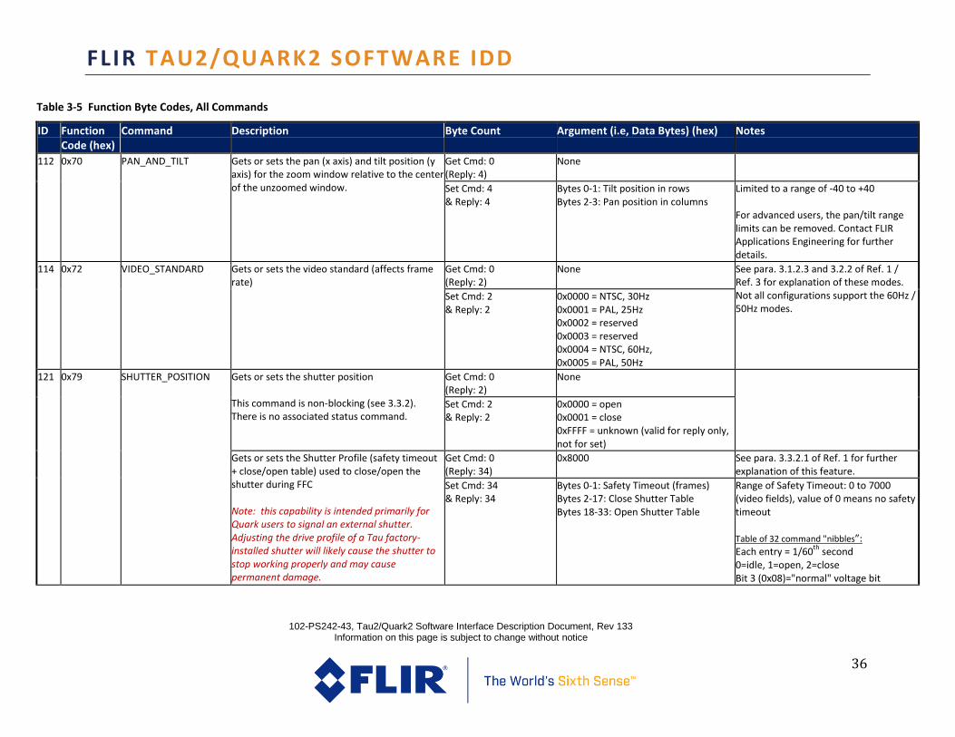
36
Table 3-5 Function Byte Codes, All Commands
ID Function Code (hex)
Command Description Byte Count Argument (i.e, Data Bytes) (hex) Notes
112 0x70 PAN_AND_TILT Gets or sets the pan (x axis) and tilt position (y axis) for the zoom window relative to the center of the unzoomed window.
Get Cmd: 0 (Reply: 4)
None
Set Cmd: 4 & Reply: 4
Bytes 0-1: Tilt position in rows Bytes 2-3: Pan position in columns
Limited to a range of -40 to +40 For advanced users, the pan/tilt range limits can be removed. Contact FLIR Applications Engineering for further details.
114 0x72 VIDEO_STANDARD Gets or sets the video standard (affects frame rate)
Get Cmd: 0 (Reply: 2)
None See para. 3.1.2.3 and 3.2.2 of Ref. 1 / Ref. 3 for explanation of these modes. Not all configurations support the 60Hz / 50Hz modes.
Set Cmd: 2 & Reply: 2
0x0000 = NTSC, 30Hz 0x0001 = PAL, 25Hz 0x0002 = reserved 0x0003 = reserved 0x0004 = NTSC, 60Hz, 0x0005 = PAL, 50Hz
121 0x79 SHUTTER_POSITION Gets or sets the shutter position This command is non-blocking (see 3.3.2). There is no associated status command.
Get Cmd: 0 (Reply: 2)
None
Set Cmd: 2 & Reply: 2
0x0000 = open 0x0001 = close 0xFFFF = unknown (valid for reply only, not for set)
Gets or sets the Shutter Profile (safety timeout + close/open table) used to close/open the shutter during FFC Note: this capability is intended primarily for Quark users to signal an external shutter. Adjusting the drive profile of a Tau factory-installed shutter will likely cause the shutter to stop working properly and may cause permanent damage.
Get Cmd: 0 (Reply: 34)
0x8000 See para. 3.3.2.1 of Ref. 1 for further explanation of this feature.
Set Cmd: 34 & Reply: 34
Bytes 0-1: Safety Timeout (frames) Bytes 2-17: Close Shutter Table Bytes 18-33: Open Shutter Table
Range of Safety Timeout: 0 to 7000 (video fields), value of 0 means no safety timeout Table of 32 command "nibbles”: Each entry = 1/60
th second
0=idle, 1=open, 2=close Bit 3 (0x08)="normal" voltage bit

FLIR TAU2/QUARK2 SOFTWARE IDD
102-PS242-43, Tau2/Quark2 Software Interface Description Document, Rev 133 Information on this page is subject to change without notice
37
Table 3-5 Function Byte Codes, All Commands
ID Function Code (hex)
Command Description Byte Count Argument (i.e, Data Bytes) (hex) Notes
130 0x82 TRANSFER_FRAME Captures a snapshot to a specified buffer location. (Capture operations must be sequential.) This command is non-blocking (see 3.3.2). There is no associated status command.
Cmd: 4 & Reply: 4
Byte 0: type 0x08 = 14-bit snapshot 0x16 = 8bit bitmap capture 0x17 = 8bit bitmap playback Byte 1: snapshot number Byte 2-3: 0x0001 For type 17, set bytes 2-3 to 0x0000 to resume live imagery.
The primary purpose of this command is to support the snapshot feature, described in para. 3.3.2.9 of Ref. 1 / Ref. 3. See FLIR’s Tau website for an Application Note that provides a detailed explanation of the command sequences required to execute snapshot capture, playback, and download. Note: The snapshot and capture commands may write to flash, and should not be performed if power may be interrupted before operation completion.

FLIR TAU2/QUARK2 SOFTWARE IDD
102-PS242-43, Tau2/Quark2 Software Interface Description Document, Rev 133 Information on this page is subject to change without notice
38
Table 3-5 Function Byte Codes, All Commands
ID Function Code (hex)
Command Description Byte Count Argument (i.e, Data Bytes) (hex) Notes
142 0x8E TLIN_COMMANDS Gets and sets the resolution of the TLinear digital video.
Get cmd: 2 Bytes 0-1: 0x0010 Output Mode: 0x0000 = Low resolution mode (0.4Kelvin/count in 14-bit digital) 0x0001 = High resolution mode (0.04 Kelvin/count in 14-bit digital)
Resp: 2 Bytes 0-1: TLin Output Mode 0x0000 = Low resolution mode 0x0001 = High resolution mode
Set cmd: 4 Resp: 0
Bytes 0-1: 0x0010 Bytes 2-3: TLin Output Mode 0x0000 = Low resolution mode 0x0001 = High resolution mode
Enables/disables TLinear output Note: With TLinear enabled, the 14-bit digital output will represent scene temperature values. The 8-bit digital output and analog video output is unaffected.
Get cmd: 2 Bytes 0-1: 0x0040 Not all configurations support the TLinear capability. This feature can only be enabled if the camera supports advanced radiometry. See para.1.2 and 3.3.3.3 of Ref. 3
Resp: 2 Bytes 0-1: TLin Enable Status
Set cmd: 4 Resp: 0
Bytes 0-1: 0x0040 Bytes 2-3: TLin Enable Status
177 0xB1 CORRECTION_ MASK Gets or sets the corrections applied This command allows various corrections / filters to be disabled. This feature is intended for advanced customers only and can degrade image quality.
Get Cmd: 0 (Reply: 2)
None Valid arguments: 0x087F (all corrections enabled, non-advanced radiometry) 0x0A7F (all corrections enabled, advanced radiometry with TLinear enabled) 0x006F (to disable temp. filter)
Set Cmd: 2 & Reply: 2
Correction mask: bit 0 -3: reserved bit 4 = temporal filter bit 5 - 15 = reserved
196 0xC4 MEMORY_STATUS Gets the status for several non-blocking write / erase commands
Cmd: 0 None For various commands that involve writing or erasing non-volatile memory (e.g. SET_DEFAULTS, WRITE_NVFFC_TABLE, ERASE_MEMORY) this command returns status. Power should not be removed from the core until the command reports that the memory operation is complete.
Reply: 2 Bytes remaining to be written 0x0000 = complete 0xFFFF = erase error 0xFFFE = write error

FLIR TAU2/QUARK2 SOFTWARE IDD
102-PS242-43, Tau2/Quark2 Software Interface Description Document, Rev 133 Information on this page is subject to change without notice
39
Table 3-5 Function Byte Codes, All Commands
ID Function Code (hex)
Command Description Byte Count Argument (i.e, Data Bytes) (hex) Notes
198 0xC6 WRITE_NVFFC_ TABLE Writes the FFC map to nonvolatile memory This command is non-blocking (see 3.3.2). The MEMORY_STATUS command (ID #196) is the associated status command.
Cmd: 0 & Reply: 0
None See para. 3.3.2.1 of Ref. 1 / Ref. 3 for further explanation of this command.
210 0xD2 READ_MEMORY Reads specified number of bytes beginning at the specified address
Cmd: 6 Bytes 0-3: Address Bytes 4-5: Number of bytes to read (maximum of 256)
Used for snapshot read. See the note associated with command ID 130 (0x82).
Reply: Specified number of bytes
Up to 256 bytes of data
212 0xD4 ERASE_MEMORY_ BLOCK
Erases a block or a range of non-volatile memory. This command is non-blocking (see 3.3.2). The MEMORY_STATUS command (ID #196) is the associated status command.
Cmd: 2 & Reply: 2
Block to be erased Used for snapshot erase. See the note associated with command ID 130 (0x82). Note: This command writes to flash, and should not be performed if power may be interrupted before operation completion.
213 0xD5 GET_NV_MEMORY_SIZE Get the base address and block size of the non-volatile memory device. (The memory block in which a particular address is located can be determined by subtracting the base address returned by GET_NV_MEMORY_SIZE from the memory address and then dividing the result by the block size returned by GET_NV_MEMORY_SIZE. )
Cmd: 2 0xFFFF Used for snapshot read. See the note associated with command ID 130 (0x82). Reply: 8 Bytes 0-3: Base Address
Bytes 4-7: Block Size (in bytes)
214 0xD6 GET_MEMORY_ ADDRESS
Gets the memory address and size of the specified buffer.
Cmd: 4 Bytes 0-3: FFFF 0013 Used for snapshot read. See the note associated with command ID 130 (0x82). Note that the number of used bytes in the snapshot area includes headers.
Reply: 8 Bytes 0-3: Base address of snapshot area Bytes 4-7: Size (in bytes)
Cmd: 4 Bytes 0-3: FFFE 0013

FLIR TAU2/QUARK2 SOFTWARE IDD
102-PS242-43, Tau2/Quark2 Software Interface Description Document, Rev 133 Information on this page is subject to change without notice
40
Table 3-5 Function Byte Codes, All Commands
ID Function Code (hex)
Command Description Byte Count Argument (i.e, Data Bytes) (hex) Notes
Reply: 8 Bytes 0-3: Number of used bytes in snapshot area Bytes 4-7: Total number of snapshots in snapshot area
Consequently, even when all snapshots are erased, the returned value will be non-zero.
Cmd: 4 Bytes 0-3: 00XX 0013
Reply: 8 Bytes 0-3: Address of snapshot XX Bytes 4-7: Size (in bytes) of snapshot XX
Cmd: 4 Bytes 0-3: 80XX 0013
Reply: 8 Bytes 0-3: 4-byte header stored with snapshot XX Bytes 4-7: Null
219 0xDB GAIN_SWITCH_ PARAMS
Gets or sets the population (as a percentage) and temperature (in deg C) thresholds for automatic high/low gain-state switching For example, if the hi-to-lo temp threshold is set to 100 and the hi-to-low population threshold is set to 20, the automatic switch to low gain state will occur when > 20% of the ROI is imaging temps >100C. If the low-to-high temp threshold is set to 90 and the low-to-high population threshold is set to 85, the automatic switch to high gain will occur when >85% of the ROI is imaging temps < 90C.
Get Cmd: 0 (Reply: 8)
None Pop. thresholds range: 0 to 100 Temp. thresholds range: 50 to 160 Note: to prevent oscillation between gain states, high-to-low temperature threshold must be greater than low-to-high threshold. Similarly the sum of the two population thresholds must be greater than 100%. See para. 3.3.2.2 of Ref. 1 / Ref. 3 for further explanation of these parameters.
Set Cmd: 8 & Reply: 8
Bytes 0-1: high-to-low temperature threshold Bytes 2-3: high-to-low population threshold Bytes 4-5: low-to-high temperature threshold Bytes 6-7: low-to-high population threshold
226 0xE2 DDE_THRESHOLD Gets or sets the threshold of the DDE filter Get Cmd: 0 (Reply: 2)
None Range: 0 to 255 See para. 3.3.2.5 of Ref. 1 / Ref. 3 for definition of this parameter. Note: Set capability has no effect in automatic DDE mode. (See SPATIAL_THRESHOLD, 0xE3.)
Set Cmd: 2 & Reply: 2
Threshold value

FLIR TAU2/QUARK2 SOFTWARE IDD
102-PS242-43, Tau2/Quark2 Software Interface Description Document, Rev 133 Information on this page is subject to change without notice
41
Table 3-5 Function Byte Codes, All Commands
ID Function Code (hex)
Command Description Byte Count Argument (i.e, Data Bytes) (hex) Notes
227 0xE3 SPATIAL_ THRESHOLD (AUTO_DDE)
Gets or sets the spatial threshold of the DDE filter and the DDE mode (auto or manual)
Get Cmd: 0 (Reply: 2)
None See para. 3.3.2.5 of Ref. 1 / Ref. 3 for definition of this parameter. The range of this parameter has been changed for the Tau 2.7 release: Auto Threshold range is -20 to 100 -20 to -1 blurs the image, 0 bypasses DDE, 1 to 100 sharpens the image
Set Cmd: 2 & Reply: 2
Bytes 0 -1: 0x0000 – 0x000F = manually specified
threshold 0x01xx automatic threshold Byte 0 = 0x01, Auto Byte 1 = 0xEC to 0x64, Threshold (-20 to 100)
Gets or sets the DDE blend mode (“halo” suppression for DDE)
Get Cmd: 4 (Resp: 4)
Byte 0-1: const_0x0002 Byte 2-3: dontCare
Set Cmd: 4 & Resp: 4
Byte 0-1: const_0x0001 Byte 2-3: Mode 0x0000 = disabled 0x0001 = enabled
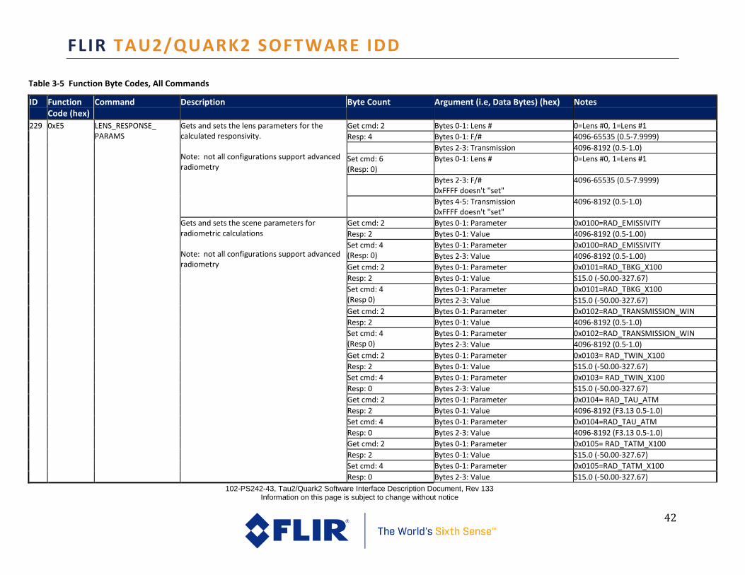
FLIR TAU2/QUARK2 SOFTWARE IDD
102-PS242-43, Tau2/Quark2 Software Interface Description Document, Rev 133 Information on this page is subject to change without notice
42
Table 3-5 Function Byte Codes, All Commands
ID Function Code (hex)
Command Description Byte Count Argument (i.e, Data Bytes) (hex) Notes
229 0xE5 LENS_RESPONSE_ PARAMS
Gets and sets the lens parameters for the calculated responsivity. Note: not all configurations support advanced radiometry
Get cmd: 2 Bytes 0-1: Lens # 0=Lens #0, 1=Lens #1
Resp: 4 Bytes 0-1: F/# 4096-65535 (0.5-7.9999)
Bytes 2-3: Transmission 4096-8192 (0.5-1.0)
Set cmd: 6 (Resp: 0)
Bytes 0-1: Lens # 0=Lens #0, 1=Lens #1
Bytes 2-3: F/# 0xFFFF doesn't "set"
4096-65535 (0.5-7.9999)
Bytes 4-5: Transmission 0xFFFF doesn't "set"
4096-8192 (0.5-1.0)
Gets and sets the scene parameters for radiometric calculations Note: not all configurations support advanced radiometry
Get cmd: 2 Bytes 0-1: Parameter 0x0100=RAD_EMISSIVITY
Resp: 2 Bytes 0-1: Value 4096-8192 (0.5-1.00)
Set cmd: 4 (Resp: 0)
Bytes 0-1: Parameter 0x0100=RAD_EMISSIVITY
Bytes 2-3: Value 4096-8192 (0.5-1.00)
Get cmd: 2 Bytes 0-1: Parameter 0x0101=RAD_TBKG_X100
Resp: 2 Bytes 0-1: Value S15.0 (-50.00-327.67)
Set cmd: 4 (Resp 0)
Bytes 0-1: Parameter 0x0101=RAD_TBKG_X100
Bytes 2-3: Value S15.0 (-50.00-327.67)
Get cmd: 2 Bytes 0-1: Parameter 0x0102=RAD_TRANSMISSION_WIN
Resp: 2 Bytes 0-1: Value 4096-8192 (0.5-1.0)
Set cmd: 4 (Resp 0)
Bytes 0-1: Parameter 0x0102=RAD_TRANSMISSION_WIN
Bytes 2-3: Value 4096-8192 (0.5-1.0)
Get cmd: 2 Bytes 0-1: Parameter 0x0103= RAD_TWIN_X100
Resp: 2 Bytes 0-1: Value S15.0 (-50.00-327.67)
Set cmd: 4 Bytes 0-1: Parameter 0x0103= RAD_TWIN_X100
Resp: 0 Bytes 2-3: Value S15.0 (-50.00-327.67)
Get cmd: 2 Bytes 0-1: Parameter 0x0104= RAD_TAU_ATM
Resp: 2 Bytes 0-1: Value 4096-8192 (F3.13 0.5-1.0)
Set cmd: 4 Bytes 0-1: Parameter 0x0104=RAD_TAU_ATM
Resp: 0 Bytes 2-3: Value 4096-8192 (F3.13 0.5-1.0)
Get cmd: 2 Bytes 0-1: Parameter 0x0105= RAD_TATM_X100
Resp: 2 Bytes 0-1: Value S15.0 (-50.00-327.67)
Set cmd: 4 Bytes 0-1: Parameter 0x0105=RAD_TATM_X100
Resp: 0 Bytes 2-3: Value S15.0 (-50.00-327.67)

FLIR TAU2/QUARK2 SOFTWARE IDD
102-PS242-43, Tau2/Quark2 Software Interface Description Document, Rev 133 Information on this page is subject to change without notice
43
Table 3-5 Function Byte Codes, All Commands
ID Function Code (hex)
Command Description Byte Count Argument (i.e, Data Bytes) (hex) Notes
Get cmd: 2 Bytes 0-1: Parameter 0x0106=RAD_ REFL _WIN
Resp: 2 Bytes 0-1: Value 0- RAD_TAU_WIN (F3.13 0.0- win)
Set cmd: 4 Bytes 0-1: Parameter 0x0106=RAD_REFL_WIN
Resp: 0 Bytes 2-3: Value 0- RAD_TAU_WIN (F3.13 0.0- win)
Get cmd: 2 Bytes 0-1: Parameter 0x0107=RAD_ TREFL _X100
Resp: 2 Bytes 0-1: Value S15.0 (-50.00-327.67)
Set cmd: 4 Bytes 0-1: Parameter 0x0107=RAD_ TREFL _X100
Resp: 0 Bytes 2-3: Value S15.0 (-50.00-327.67)

FLIR TAU2/QUARK2 SOFTWARE IDD
102-PS242-43, Tau2/Quark2 Software Interface Description Document, Rev 133
Information on this page is subject to change without notice
44
3.4 SUMMARIZED COMMAND LISTS The lists below are subsets of Table 2-4, each showing all the commands related to a particular aspect of Tau 2 / Quark operation. List of FFC-related commands:
ID Function Code (hex)
Command
11 0x0B FFC_MODE_ SELECT
12 0x0C DO_FFC
13 0x0D FFC_PERIOD
14 0x0E FFC_TEMP_ DELTA
60 0x3C FFC_WARN_TIME
121 0x79 SHUTTER_POSITION
198 0xC6 WRITE_NVFFC_TABLE
List of commands related to Analog Video / BT.656 digital video and AGC:
ID Function Code (hex)
Command
15 0x0F VIDEO_MODE
16 0x10 VIDEO_PALETTE
19 0x13 AGC_TYPE
20 0x14 CONTRAST
21 0x15 BRIGHTNESS
24 0x18 BRIGHTNESS_BIAS
27 0x1B TAIL_SIZE
28 0x1C ACE_CORRECT
37 0x25 TEST_ PATTERN
38 0x26 VIDEO_COLOR_MODE
43 0x2B SPOT_DISPLAY
47 0x2F SYMBOL_CONTROL
49 0x31 SPLASH_CONTROL
50 0x32 EZOOM_CONTROL
62 0x3E AGC_FILTER
63 0x3F PLATEAU_LEVEL

FLIR TAU2/QUARK2 SOFTWARE IDD
102-PS242-43, Tau2/Quark2 Software Interface Description Document, Rev 133
Information on this page is subject to change without notice
45
76 0x4C AGC_ROI
85 0x55 AGC_MIDPOINT
106 0x6A MAX_AGC_GAIN
112 0x70 PAN_AND_TILT
114 0x72 VIDEO_STANDARD
List of radiometry-related commands:
ID Function Code (hex)
Command
10 0x0A GAIN_MODE
31 0x1F SPOT_METER_ MODE
34 0x22 ISOTHERM
35 0x23 ISOTHERM_ THRESHOLDS
42 0x2A GET_SPOT_METER
43 0x2B SPOT_DISPLAY
67 0x43 GET_SPOT_METER_ DATA
77 0x4D SHUTTER_TEMP
142 0x8E TLIN_COMMANDS
219 0xDB GAIN_SWITCH_ PARAMS
229 0xE5 LENS_RESPONSE_PARAMS
List of DDE-related commands:
ID Function Code (hex)
Command
44 0x2C DDE_GAIN
226 0xE2 DDE_THRESHOLD
227 0xE3 SPATIAL_ THRESHOLD (AUTO_DDE)

FLIR TAU2/QUARK2 SOFTWARE IDD
102-PS242-43, Tau2/Quark2 Software Interface Description Document, Rev 133
Information on this page is subject to change without notice
46
List of snapshot-related commands: ID Function
Code (hex) Command
130 0x82 TRANSFER_FRAME
196 0xC4 MEMORY_STATUS
210 0xD2 READ_MEMORY
212 0xD4 ERASE_MEMORY_ BLOCK
213 0xD5 GET_NV_MEMORY_SIZE
214 0xD6 GET_MEMORY_ ADDRESS
Note: See FLIR’s Tau website for an Application Note that provides a detailed explanation of the proper command sequences to implement snapshot capture, playback, and download.
3.5 EXAMPLE FORMAT OF A SERIAL MESSAGE
The packet depictions below illustrate the incoming message when the FFC_MODE_SELECT command (0x0B) is issued to get current setting and the reply message assuming the current FFC mode is “automatic” (argument = 0x0001): Incoming message: Process Code
Status Reserved Function Byte Count CRC Data CRC
0x6E 0x00 0x00 0x0B 0x0000 0x2F4A 0x0000
Reply message: Process Code
Status Reserved Function Byte Count CRC Data CRC
0x6E 0x00 0x00 0x0B 0x0002 0x0F08 0x0001 0x1021
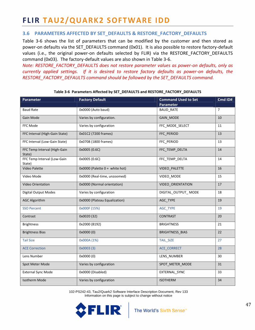
FLIR TAU2/QUARK2 SOFTWARE IDD
102-PS242-43, Tau2/Quark2 Software Interface Description Document, Rev 133
Information on this page is subject to change without notice
47
3.6 PARAMETERS AFFECTED BY SET_DEFAULTS & RESTORE_FACTORY_DEFAULTS
Table 3-6 shows the list of parameters that can be modified by the customer and then stored as power-on defaults via the SET_DEFAULTS command (0x01). It is also possible to restore factory-default values (i.e., the original power-on defaults selected by FLIR) via the RESTORE_FACTORY_DEFAULTS command (0x03). The factory-default values are also shown in Table 3-6. Note: RESTORE_FACTORY_DEFAULTS does not restore parameter values as power-on defaults, only as currently applied settings. If it is desired to restore factory defaults as power-on defaults, the RESTORE_FACTORY_DEFAULTS command should be followed by the SET_DEFAULTS command.
Table 3-6 Parameters Affected by SET_DEFAULTS and RESTORE_FACTORY_DEFAULTS
Parameter Factory Default Command Used to Set Parameter
Cmd ID#
Baud Rate 0x0000 (Auto baud) BAUD_RATE 7
Gain Mode Varies by configuration. GAIN_MODE 10
FFC Mode Varies by configuration FFC_MODE_SELECT 11
FFC Interval (High-Gain State) 0x01C2 (7200 frames) FFC_PERIOD 13
FFC Interval (Low-Gain State) 0x0708 (1800 frames) FFC_PERIOD 13
FFC Temp Interval (High-Gain State)
0x0005 (0.6C) FFC_TEMP_DELTA 14
FFC Temp Interval (Low-Gain State)
0x0005 (0.6C) FFC_TEMP_DELTA 14
Video Palette 0x0000 (Palette 0 = white hot) VIDEO_PALETTE 16
Video Mode 0x0000 (Real-time, unzoomed) VIDEO_MODE 15
Video Orientation 0x0000 (Normal orientation) VIDEO_ORIENTATION 17
Digital Output Modes Varies by configuration DIGITAL_OUTPUT_ MODE 18
AGC Algorithm 0x0000 (Plateau Equalization) AGC_TYPE 19
SSO Percent 0x000F (15%) AGC_TYPE 19
Contrast 0x0020 (32) CONTRAST 20
Brightness 0x2000 (8192) BRIGHTNESS 21
Brightness Bias 0x0000 (0) BRIGHTNESS_BIAS 22
Tail Size 0x000A (1%) TAIL_SIZE 27
ACE Correction 0x0003 (3) ACE_CORRECT 28
Lens Number 0x0000 (0) LENS_NUMBER 30
Spot Meter Mode Varies by configuration SPOT_METER_MODE 31
External Sync Mode 0x0000 (Disabled) EXTERNAL_SYNC 33
Isotherm Mode Varies by configuration ISOTHERM 34

FLIR TAU2/QUARK2 SOFTWARE IDD
102-PS242-43, Tau2/Quark2 Software Interface Description Document, Rev 133
Information on this page is subject to change without notice
48
Lower Isotherm Threshold 0x005A (90%) ISOTHERM_ THRESHOLDS 35
Middle Isotherm Threshold 0x005C (92%) ISOTHERM_ THRESHOLDS 35
Upper Isotherm Threshold 0x005F (95%) ISOTHERM_ THRESHOLDS 35
Saturation Isotherm Threshold 0x0064 (100%) ISOTHERM_ THRESHOLDS 35
Video Color Mode 0x0001 (Color enabled) VIDEO_COLOR_MODE 38
Spot Display Mode Varies by configuration SPOT_DISPLAY 43
DDE Gain n/a (auto) DDE_GAIN 44
Ezoom Width Max value (varies by config.) EZOOM_CONTROL 50
FFC Warn Time 0x003C (60 frames) FFC_WARN_TIME 60
AGC Filter 0x0010 (16) AGC_FILTER 62
Plateau Level Varies by configuration PLATEAU_LEVEL 63
Spot Meter Coordinates Varies by configuration GET_SPOT_METER_ DATA 67
ROI Coordinates Top: -50% Left: -50% Bottom: +50% Right: +50%
AGC_ROI 76
2X Zoom ROI Coordinates Not used in Tau 2.1 AGC_ROI 76
4X Zoom ROI Coordinates Not used in Tau 2.1 AGC_ROI 76
8X Zoom ROI Coordinates Not used in Tau 2.1 AGC_ROI 76
AGC Midpoint 0x007F (127) AGC_MIDPOINT 85
Max. Gain 0x0008 (8) MAX_AGC_GAIN 106
Pan / Tilt Coordinates 0,0 PAN_AND_TILT 112
Video Standard Varies by configuration VIDEO_STANDARD 114
TLinear Enable Varies by configuration TLIN_COMMANDS 142
TLinear Resolution Varies by configuration TLIN_COMMANDS 142
Shutter Profile Varies by configuration SHUTTER_POSITION 121
Correction Mask 0x083F (all enabled except supplemental offset) CORRECTION_MASK 177
Gain Switch, High-to-Low Temperature Threshold
0x008C (140C) GAIN_SWITCH_PARAMS 219
Gain Switch, Low-to-High Temperature Threshold
0x0064 (100C) GAIN_SWITCH_PARAMS 219
Gain Switch, High-to-Low Population Threshold
0x005F (95%) GAIN_SWITCH_PARAMS 219
Gain Switch, Low-to-High Population Threshold
0x0014 (20%) GAIN_SWITCH_PARAMS 219
DDE Threshold n/a (default mode is automatic) DDE_THRESHOLD 226
DDE Mode / Spatial Threshold 0x010A (Byte 0: 01, automatic mode) SPATIAL_THRESHOLD 227

FLIR TAU2/QUARK2 SOFTWARE IDD
102-PS242-43, Tau2/Quark2 Software Interface Description Document, Rev 133
Information on this page is subject to change without notice
49
DDE Blend Mode 0x0001 (enabled) SPATIAL_THRESHOLD 227
Lens Response Parameters Varies by configuration LENS_RESPONSE_ PARAMETERS 229

FLIR TAU2/QUARK2 SOFTWARE IDD
102-PS242-43, Tau2/Quark2 Software Interface Description Document, Rev 133
Information on this page is subject to change without notice
50
© FLIR Commercial Systems, 2012. All rights reserved worldwide. No parts of this manual, in whole or in part, may
be copied, photocopied, translated, or transmitted to any electronic medium or machine readable form without
the prior written permission of FLIR Commercial Systems Names and m a r k s appearing on the p r o d u c t s herein are either registered trademarks or trademarks of FLIR
Commercial Systems and/or its subsidiaries. All other trademarks, trade names, or company names referenced
herein are used for identification only and a r e the property of their respective owners. Liberation fonts are copyright 2009 by RedHat and ar e used under authority of the GNU public license. Information
about these fonts and t h e G N U public license can b e found at: https://www.redhat.com/promo/fonts/. This product is protected by patents, design patents, patents pending, or design patents pending. If you have q u e s t i o n s that are not covered in this m anual , or need service, contact FLIR Commercial Systems
Customer Support at 805.964.9797 for additional information prior t o returning a camera. This documentation and the requirements specified herein are subject to change without notice.
This equipment must be disposed of as electronic waste.
Contact your nearest FLIR Commercial Systems, Inc. representative for instructions on how to return
the p r o d u c t to FLIR for proper disposal.
FCC Notice. This device is a subassembly designed for incorporation into other products in order to provide an infrared camera function. It is not an end-product fit for consumer use. When incorporated into a host device, the end-product will generate, use, and radiate radio frequency energy that may cause radio interference. As such, the end-product incorporating this subassembly must be tested and approved under the rules of the Federal Communications Commission (FCC) before the end-product may be offered for sale or lease, advertised, imported, sold, or leased in the United States. The FCC regulations are designed to provide reasonable protection against interference to radio communications. See 47 C.F.R. §§ 2.803 and 15.1 et seq. Industry Canada Notice. This device is a subassembly designed for incorporation into other products in order to provide an infrared camera function. It is not an end-product fit for consumer use. When incorporated into a host device, the end-product will generate, use, and radiate radio frequency energy that may cause radio interference. As such, the end-product incorporating this subassembly must be tested for compliance with the Interference-Causing Equipment Standard, Digital Apparatus, ICES-003, of Industry Canada before the product incorporating this device may be: manufactured or offered for sale or lease, imported, distributed, sold, or leased in Canada. Avis d’Industrie Canada. Cet appareil est un sous-ensemble conçu pour être intégré à un autre produit afin de fournir une fonction de caméra infrarouge. Ce n’est pas un produit final destiné aux consommateurs. Une fois intégré à un dispositif hôte, le produit final va générer, utiliser et émettre de l’énergie radiofréquence qui pourrait provoquer de l’interférence radio. En tant que tel, le produit final intégrant ce sous-ensemble doit être testé pour en vérifier la conformité avec la Norme sur le matériel brouilleur pour les appareils numériques (NMB-003) d’Industrie Canada avant que le produit intégrant ce dispositif puisse être fabriqué, mis en vente ou en location, importé, distribué, vendu ou loué au Canada. EU Notice. This device is a subassembly or component intended only for product evaluation, development or incorporation into other products in order to provide an infrared camera function. It is not a finished end-product fit for general consumer use. Persons handling this device must have appropriate electronics training and observe good engineering practice standards. As such, this product does not fall within the scope of the European Union (EU) directives regarding electromagnetic compatibility (EMC). Any end-product intended for general consumer use that incorporates this device must be tested in accordance and comply with all applicable EU EMC and other relevant directives.