FlexCampus Reference Architecture Guide - hp. · PDF fileReference Architecture Guide ......
52
FlexCampus Reference Architecture Guide HP Networking Technical Marketing Table of contents Introduction ......................................................................................................................................... 2 HP FlexNetwork Architecture ............................................................................................................. 2 HP FlexCampus ............................................................................................................................... 4 Campus Trends ................................................................................................................................ 4 FlexCampus Switching and Routing ....................................................................................................... 7 HP Meshed Stacking ........................................................................................................................ 7 General Requirements ...................................................................................................................... 9 Physical Infrastructure Models .......................................................................................................... 13 Logical Infrastructure Models ........................................................................................................... 20 FlexCampus Mobility.......................................................................................................................... 27 Wireless Technology Highlights ....................................................................................................... 27 Wireless Architectures .................................................................................................................... 27 FlexCampus Network Management ..................................................................................................... 33 Single pane-of-glass network management ........................................................................................ 33 HP IMC Features ............................................................................................................................ 33 The IMC Base Platform and Service Modules ..................................................................................... 34 HP IMC Base Platform Deployment Options....................................................................................... 36 HP IMC Add-on Modules Deployment Options .................................................................................. 38 FlexCampus Security .......................................................................................................................... 40 Overview ...................................................................................................................................... 40 Trusted Infrastructure ....................................................................................................................... 41 Unified Access Control ................................................................................................................... 44 Intrusion Prevent System (IPS) ........................................................................................................... 46 Summary....................................................................................................................................... 48 FlexCampus Reference Designs ........................................................................................................... 49 2-Tier FlexCampus.......................................................................................................................... 49 3-Tier FlexCampus.......................................................................................................................... 50 Product Options ............................................................................................................................. 51
Transcript of FlexCampus Reference Architecture Guide - hp. · PDF fileReference Architecture Guide ......

FlexCampus
Reference Architecture Guide
HP Networking Technical Marketing
Table of contents
Introduction ......................................................................................................................................... 2 HP FlexNetwork Architecture ............................................................................................................. 2 HP FlexCampus ............................................................................................................................... 4 Campus Trends ................................................................................................................................ 4
FlexCampus Switching and Routing ....................................................................................................... 7 HP Meshed Stacking ........................................................................................................................ 7 General Requirements ...................................................................................................................... 9 Physical Infrastructure Models .......................................................................................................... 13 Logical Infrastructure Models ........................................................................................................... 20
FlexCampus Mobility .......................................................................................................................... 27 Wireless Technology Highlights ....................................................................................................... 27 Wireless Architectures .................................................................................................................... 27
FlexCampus Network Management ..................................................................................................... 33 Single pane-of-glass network management ........................................................................................ 33 HP IMC Features ............................................................................................................................ 33 The IMC Base Platform and Service Modules ..................................................................................... 34 HP IMC Base Platform Deployment Options ....................................................................................... 36 HP IMC Add-on Modules Deployment Options .................................................................................. 38
FlexCampus Security .......................................................................................................................... 40 Overview ...................................................................................................................................... 40 Trusted Infrastructure ....................................................................................................................... 41 Unified Access Control ................................................................................................................... 44 Intrusion Prevent System (IPS) ........................................................................................................... 46 Summary....................................................................................................................................... 48
FlexCampus Reference Designs ........................................................................................................... 49 2-Tier FlexCampus .......................................................................................................................... 49 3-Tier FlexCampus .......................................................................................................................... 50 Product Options ............................................................................................................................. 51
Introduction
HP FlexNetwork Architecture
A new dawn of technology innovation is driving unprecedented change. Mobility, virtualization, high-
definition video, rich-media collaboration tools, and cloud computing are reinventing how
businesses—and people—work. Enterprises that can harness these innovations will have new tools to
drive business advantage and build new opportunities in the global marketplace.
When legacy networks are pushed to the limit, they become fragile, difficult to manage, vulnerable,
and expensive to operate. Businesses whose networks are at this breaking point, risk missing the next
wave of opportunity.
Application-driven, service-oriented architectures (SOA), and virtualization have banished the client-
server model from the data center. Cloud computing also makes heavy use of server virtualization,
which reshapes data center traffic flows and increases bandwidth demands at the server edge. By
2014, network planners should expect more than 80 percent of traffic in the data center’s local area
network (LAN) to be between servers.1
These efforts at flexibility can be hampered by legacy data center networks. They cannot provide high
enough bandwidth and low enough latency between server connections to support highly mobile
virtual workloads.
As business volumes rise, traffic levels are exploding. Virtualization has taken root across businesses
of all sizes. Today, roughly 20 percent of all workloads are virtualized, and Gartner expects that this
will hit 50 percent by year-end 2012, and continue to grow beyond this level.2 Traffic within the
server rack is expected to grow by 25 times. Steeped in technology at home, business workers have
quickly acclimated to a rich-media experience and are using video and interactive collaboration tools.
By 2013, more than 25 percent of the documents that workers see in a day will be dominated by
pictures, video, and audio.3 New video applications will push network capacity needs by four to ten
times above current average levels.4
Legacy networks, with their decade-old architectures, will be crushed by the onslaught of applications,
virtualization, and rich media. Conventional three-tier data center networks cannot meet the security,
agility, and performance requirements of virtualized cloud computing environments. The legacy three-
tier network architecture is constrained by oversubscribed, low bandwidth and high latency—the
exact opposite of what video collaboration requires.
Mobility has quickly become a right, not a privilege. By 2013, the combined installed base of
smartphones and browser-equipped enhanced phones will exceed 1.82 billion units.5 The preferred
way to connect will be through wireless LAN (WLAN), rather than lower speed 3G or 4G networks.
Workers need to access applications and content from anywhere to stay productive, and that means
applications must be delivered flawlessly from a virtual data center to a virtual workplace.
Yet many enterprises have experienced disappointing results with their existing WLAN deployments
because of a poor user experience and a network that doesn’t scale to meet the demand for mobility.
The embrace of smartphones and tablets at work will also break the traditional models for identity
management and security that allow access based on a network port, rather than a user’s identity.
Today’s networks must be designed to meet the unique requirements of the data center, corporate
campus, and branch office. By segmenting their networks, enterprises will be able to more easily
1 Gartner, Inc., “Your Data Center Network Is Heading for Traffic Chaos,” Bjarne Munch, 27 April 2011. 2 Gartner, Inc., “Emerging Technology Analysis: How Virtual Switches Are Solving Virtualization Issues in the Data Center,” Severine Real,
16 November 2010. 3 Gartner, Inc., “The Gartner Enterprise Content Management and Related Technologies Vendor Guide, 2010” 9 August 2010. 4 Gartner, Inc., “Hype Cycle for Networking and Communications” August 2010. 5 Gartner Inc., “Gartner’s Top Predictions for IT Organizations and Users, 2011 and Beyond: IT’s Growing Transparency,” Brian Gammage et al, 23
November 2010.
align business initiatives with the underlying network requirements. Enterprises can create functional
building blocks that will meet the requirements of the specific application or business service.
With this segmentation of functional building blocks, businesses can choose best-in-class solutions that
fit their needs, rather than being locked into a one-size-fits-all solution. By using standard protocols at
the boundaries, businesses can enable interoperability among the network segments and gain both
agility and scale.
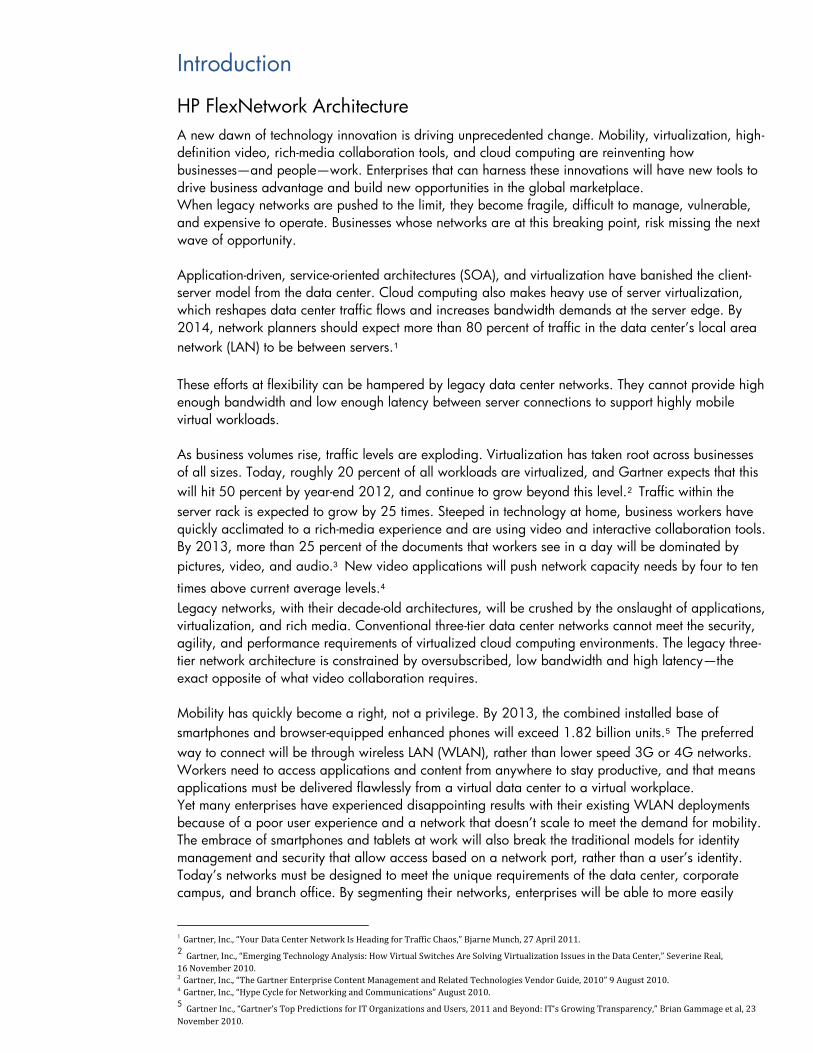
The HP FlexNetwork Architecture and its functional building blocks (Refer figure 1) are a key
component of the HP Converged Infrastructure. Enterprises can align their networks with their business
needs—even as they change—by segmenting their networks into four interrelated modular building
blocks that comprise the HP FlexNetwork Architecture: FlexFabric, FlexCampus, FlexBranch, and
FlexManagement.
FlexManagement converges network management and orchestration. FlexFabric converges and
secures the data center network with compute and storage. FlexCampus converges wired and
wireless networks to deliver media-optimized, secure, identity-based access and FlexBranch converges
network functionality and services for simplicity in the branch office.
The HP FlexNetwork architecture is designed to allow IT to manage these different network segments
through a single pane-of-glass management application, HP Intelligent Management Center (IMC).
Due to the fact that the FlexNetwork architecture is based on open standards, enterprises have the
freedom to choose the best-in-class solution for their businesses.
Even with the shift to the cloud, the HP FlexNetwork architecture is ideal for supporting this move.
Enterprises deploying private clouds must implement flatter, simpler data center networks to support
the bandwidth-intensive, delay-sensitive server-to-server virtual machine, and workload traffic flows
that are associated with cloud computing. They must also be able to administer and secure virtual
resources, and orchestrate on-demand services. HP FlexNetwork helps enterprises to securely deploy
and centrally orchestrate video, cloud, and mobile-optimized architectures that scale from the data
center to the network edge.
Figure 1: FlexNetwork Architecture

HP FlexNetwork Architecture Benefits
HP FlexCampus
Campus networks must evolve to support user requirements for interactive and video-rich, on-demand
applications and services. Management of identity and security need to be at the forefront and
backed by industry-leading vulnerability research. Campus networks must transform to easily support
the delivery of applications and services to wired and mobile workers alike.
The HP FlexCampus solution delivers a superior user experience, simplifies network architecture and
management, and ensures performance and agility at the network edge to meet today’s business
realities. Enterprises deploying a FlexCampus solution gain a secure, flexible, and agile campus LAN
infrastructure that can deliver video and other demanding applications, whether hosted in corporate
data center or the cloud, to wired or wireless users anywhere on the corporate campus.
FlexCampus is based on an advanced two-tier switching architecture that improves the performance
of media-rich collaboration applications. With FlexCampus, enterprises can eliminate or reduce the
aggregation layer, which improves network performance and reduces cost.
For greater simplicity and savings, IT staff can manage the entire network from a single pane-of-glass
network management platform.
Campus Trends
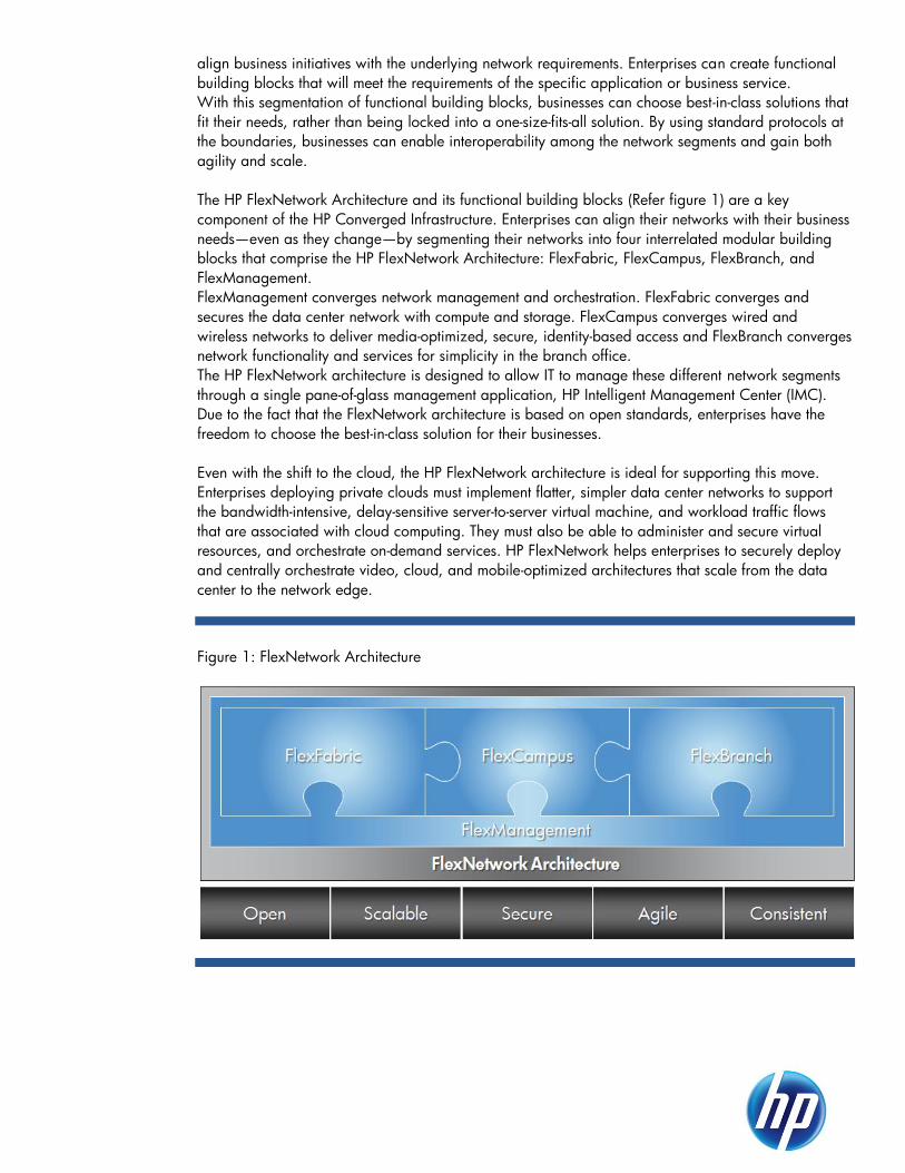
Data Center Consolidation and Cloud Computing
In the past, a campus had most of its applications running on local servers. Today, the trend is to
consolidate all servers and services in a single, centralized data center or to locate the services in a
private cloud.
Figure 2: Data Center Consolidation and Cloud Computing
The reasons behind this trend are multiple:
Operational: it is easier to maintain (install, monitor, update, troubleshoot) the systems if
they are all located in the same place.
Resources: no need to duplicate application servers, storage, backup resources as well as
expert human assets.
In any of these cases, applications are accessed remotely via a WAN or a VPN, and the total
bandwidth available for these applications is limited by these links.
Application Architecture and Virtual Clients
In the past, typical business applications where based on the client-server model. Different
implementations of the client-server model would have differing functions at the client and at the server
side, requiring differing levels of traffic between the client and the server. For example, some table
lookups would be implemented directly in the server; while in others, whole tables would have to be
transferred to the client for the search.
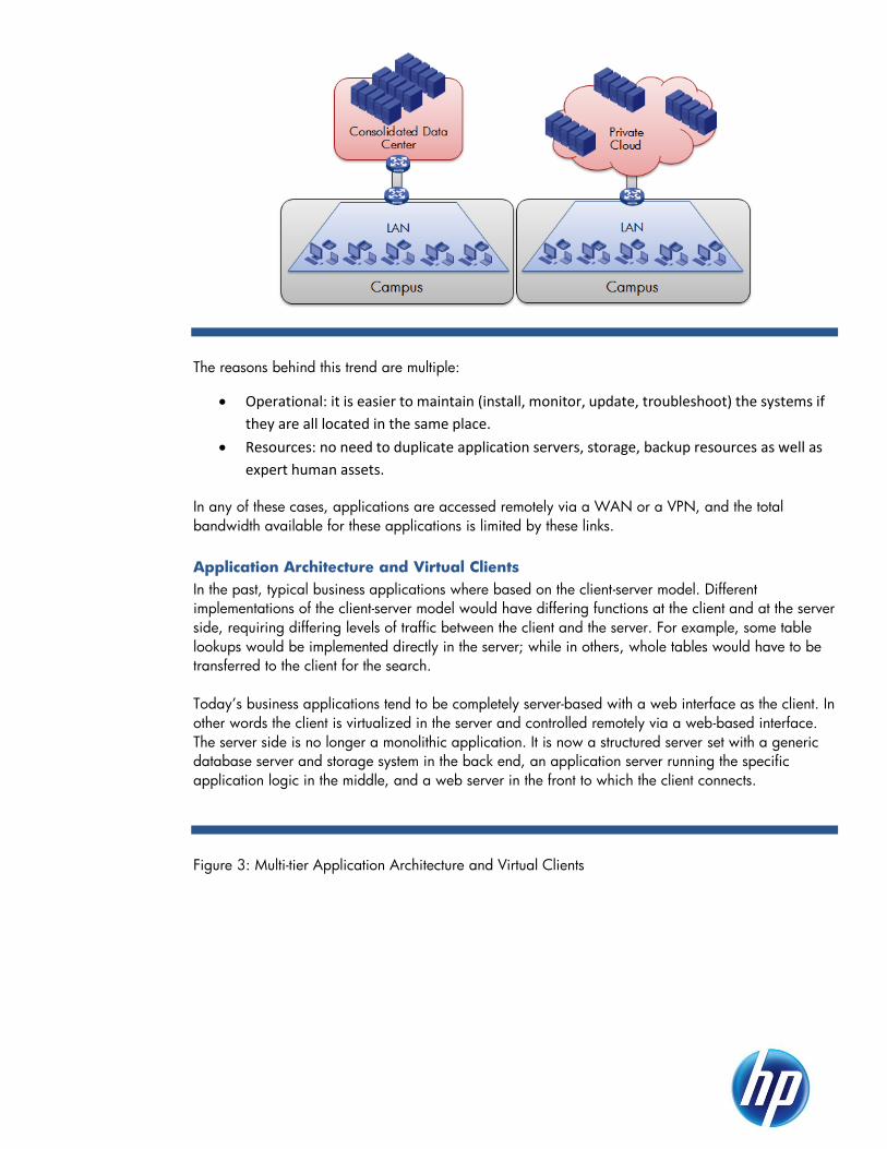
Today’s business applications tend to be completely server-based with a web interface as the client. In
other words the client is virtualized in the server and controlled remotely via a web-based interface.
The server side is no longer a monolithic application. It is now a structured server set with a generic
database server and storage system in the back end, an application server running the specific
application logic in the middle, and a web server in the front to which the client connects.
Figure 3: Multi-tier Application Architecture and Virtual Clients
In this scheme, the traffic between the user’s station and the server system is minimal, except possibly
when printing. This works well in the remote datacenter / cloud environment because it makes the use
of WAN/VPN links possible.
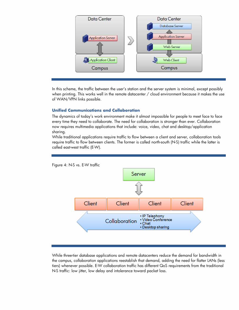
Unified Communications and Collaboration
The dynamics of today’s work environment make it almost impossible for people to meet face to face
every time they need to collaborate. The need for collaboration is stronger than ever. Collaboration
now requires multimedia applications that include: voice, video, chat and desktop/application
sharing.
While traditional applications require traffic to flow between a client and server, collaboration tools
require traffic to flow between clients. The former is called north-south (N-S) traffic while the latter is
called east-west traffic (E-W).
Figure 4: N-S vs. E-W traffic
While three-tier database applications and remote datacenters reduce the demand for bandwidth in
the campus, collaboration applications reestablish that demand, adding the need for flatter LANs (less
tiers) whenever possible. E-W collaboration traffic has different QoS requirements from the traditional
N-S traffic: low jitter, low delay and intolerance toward packet loss.

FlexCampus Switching and Routing
HP Meshed Stacking
HP Meshed Stacking is a device aggregation technology that allows the interconnection of two or
more switches to form a single logical switching entity. From the point of view of an external switch,
these ―virtual‖ switches behave as a single switch in all aspects: a single Ethernet switch, a single
routing peer and a single managed device (for example: a single SNMP object instance).
HP Meshed Stacking can be defined as an infrastructural feature as it allows for the simplification of
the physical and logical infrastructure.
Figure 1.1: HP Meshed Stacking
As shown in the figure above, an aggregated switch can be imagined as a single chassis based
switch.
HP Meshed Stacking
Meshed Stacking is another advanced HP technology available in the 3800 switch series. Up to 10
3800 switches can be aggregated to form a Meshed Stack.
From the functional point of view, it is similar to IRF. The main differences are:
1. Interconnection: Meshed Stacking uses a special module and dedicated cables to
interconnect the members of the fabric. Each stacking cable can carry 40Gbps of traffic in
each direction for a total of 80Gbps.
2. Topologies: daisy-chain, ring and full mesh are supported.
Figure 1.3: HP Meshed Stacking
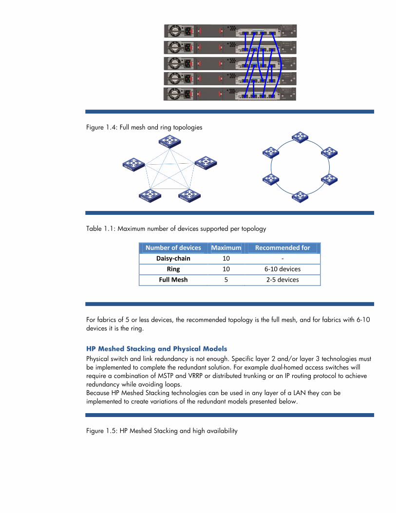
Figure 1.4: Full mesh and ring topologies
Table 1.1: Maximum number of devices supported per topology
Number of devices Maximum Recommended for
Daisy-chain 10 -
Ring 10 6-10 devices
Full Mesh 5 2-5 devices
For fabrics of 5 or less devices, the recommended topology is the full mesh, and for fabrics with 6-10
devices it is the ring.
HP Meshed Stacking and Physical Models
Physical switch and link redundancy is not enough. Specific layer 2 and/or layer 3 technologies must
be implemented to complete the redundant solution. For example dual-homed access switches will
require a combination of MSTP and VRRP or distributed trunking or an IP routing protocol to achieve
redundancy while avoiding loops.
Because HP Meshed Stacking technologies can be used in any layer of a LAN they can be
implemented to create variations of the redundant models presented below.
Figure 1.5: HP Meshed Stacking and high availability

These variations provide high availability without the need for complex protocol combinations:
Layer 2 redundancy is implemented by creating link aggregation groups with ports located
in the different physical switches
Layer 3 gateway or routing redundancy is achieved by the control plane of the aggregated
switch
General Requirements
Before introducing the FlexCampus Switching and Routing infrastructure, it is important to analyze the
general requirements that must be taken into account:
1. User related
2. Application related
3. Endpoint devices
4. High availability
User Related Requirements
In relationship to the users, it is important to know:
1. The total number of users
2. How they are going to connect to the network: wired or wireless, and if the first case, at
what speed
3. Their geographical distribution: how many buildings, how many floors in each building,
distance between buildings. Is the area between buildings private or public?
4. What applications will users use the most? A simple user profile can be created.
Figure 1.6: User Requirements

With this information, it is possible to determine the number of access switches, the number of
ports per switch, the bandwidth and QoS requirements.
Application Related Requirements
In terms of applications, the most important information is:
1. Will business/database applications be used?
a. What is their architecture: client only, client-server, web-based client?
b. Where are the servers located: in a local server-farm, in a remote datacenter, in a
private cloud, in a public cloud?
c. How many users are going to run each application, and where are these users
located?
2. Which communication and collaboration tools are going to be used: IP telephony, video
conferencing, integrated voice, video, desktop and chat?
Figure 1.7: Application Requirements
Endpoint Devices
Besides personal computers, other devices can be connected to the network. IP cameras and IP
phones are the most common, but WLAN Access Points can also be considered an endpoint device
from an architectural point of view.
Figure 1.8: Endpoint devices

These devices may require:
Additional ports and bandwidth
Multicast switching and routing
QoS policies, prioritization in particular
Special VLANs, for example: Voice VLAN
PoE
High Availability Requirements
Depending on the nature of the organization that owns the campus and/or the applications used,
different levels of availability may be required. Some organizations may need a fully redundant
network while others can cope with short periods of downtime or performance degradation.
High availability will require protection against many factors:
1. Downtime caused by maintenance activities like software updates
2. Device and device parts failure
3. Link failure
4. Attacks and security breaches (see FlexCampus Security)
Figure 1.9: High Availability
The availability requirements will impact the total cost of ownership. If the network is at the core of the
business, high availability is critical and a high level of redundancy is required. In other cases, short
downtimes may be acceptable and the cost of 100% redundancy may not be justified.
There are two main aspects of availability:
1. High availability can be achieved at the device level, link level, and/or network level.
a. Device level availability can be improved by duplicating components as, in the case
of a modular switch, the management module and power supplies; or by
duplicating the whole device, such as using device aggregation technologies.
b. Link level redundancy can be achieved by implementing layer 2 technologies like
802.3 Link Aggregation and Distributed Trunking.

c. Network level redundancy can be implemented by using redundancy protocols like
STP/RSTP/MSTP and SmartLink combined with VRRP or by implement redundant
routing environments by using OSPF, IS-IS or other fast converging protocols.
2. Is performance degradation acceptable?
For example: if the network experiences a temporary 25% loss in performance, is that
acceptable or would the impact be dangerous for the business?
A similar question: is it acceptable if a small number of users lose access for a short period
of time?
This is an important question because the cost difference between full redundancy and a
situation in which the network still works but at a slower speed can be relevant. Of
course, this question can be asked at the different levels detailed above: device, link and
network.

Physical Infrastructure Models
Introduction
A local area network covering a campus is basically a set of interconnected devices that transport
traffic:
1. Between clients and servers in traditional business applications
a. Including between internal clients and Internet services
2. Between clients in collaboration applications
Figure 1.10: Multi-tier campus LAN
Currently, the optimal models for a campus LAN are based on a structured, multi-tier approach.
In the simplest 1-tier LAN, a single switch (or switch fabric) connects clients to servers and services.
This model is usually applied to small and medium sized branches. However, in medium to large
campuses, one switching layer is usually not enough.
Using HP technologies, a 2-tier model can be applied to most campuses. In a 2-tier LAN, all client
devices connect to the client access layer and a core layer connects the client access switches to the
services.
There are cases, however, especially in multi-building campuses, where an additional layer is
required between the core and the access layers. This additional layer is called the aggregation or
distribution layer.
It is important to note in the case of a local data center or server farm, the services part of the network
can also be structured and multi-tiered. For example, the servers can be connected to a server access
layer that is itself connected to the LAN core.
Figure 1.11: 2- and 3-tier LANs

Figure 1.12: Typical single building/2-tier Campus LAN
Figure 1.13: Typical multi-building/3-tier Campus LAN
However, the actual design must be analyzed on a case by case basis. In some cases, a single or few
remote building(s) will require an aggregation switch, while the rest of the LAN requires only two
tiers. In others, the size of a building will lead to adding aggregation switches. And in some multi-
building situations, multiple fibers will run between buildings and the aggregation layer will not be
required, especially when these buildings have a small number of clients and, as a consequence, a
small number of access switches.
Access Layer
The access layer is composed of switches to which the client devices are connected. Access switches
connect to the next layer (core or aggregation) by means of uplink ports. Client devices are mostly
PCs and IP phones. In many cases, WLAN access points are also connected to the access switches.
Additionally, surveillance cameras and other endpoint devices can be connected.
Access switches may be required to offer some of the following features:

1. A balanced relation between the number and speed of the access ports and the uplink
ports
2. VLANs: Including MAC-based and voice VLANs for endpoint devices
3. IP routing
4. IGMP snooping or multicast routing
5. QoS/DiffServ boundary node features like traffic classification, remarking and prioritization
6. PoE or PoE+ for IP phones, APs and IP Cameras
7. Security: access control (see the FlexCampus Security section below)
8. LLDP for discovery of IP phones and other peripherals
Aggregation Layer
In those cases where this layer is present, most of the routing will be provided here. Aggregation
switches may also be used to host service modules like WLAN Controllers. Requirements for
aggregation layer switches may be:
1. High-speed switching and routing
2. Similar bandwidth towards the access and the core layers
3. High availability
Core Layer
Specific core layer requirements are:
1. High port density
2. High-speed routing and switching
3. High availability
4. DC power (in some cases)
2-Tier Physical Infrastructure Models
There are three types of 2-tier models.
Non-redundant
o Composed of a single core switch connected to all access switches
o If there is a need for uplink redundancy, 802.3 Link Aggregation (LACP) can be used
o Switches at the two tiers can use internal redundancy, such as redundant
management, fabric and power, providing a reasonable amount of redundancy
Figure 1.14: Non-redundant 2-tier LAN

Traditional redundant core and uplinks:
o add another core switch interconnected to the first by a high-speed link
o have two uplinks per access switch creating a dual-homed access layer
o if there is also a service access layer, these switches are also dual-homed
o if there are servers directly connected to the core, they are dual-homed
Figure 1.15: Traditional 2-tier LAN with redundant core and uplinks
HP Optimized / fully redundant
o Switch and link aggregation is implemented to achieve full redundancy, fault
tolerance and load-balancing with active-active links and devices
Layer 2 redundancy is provided by the link aggregation groups
Layer 3 redundancy is provided by the internal mechanisms of the HP
Meshed Stacking technology
Figure 1.16: HP Optimized 2-tier

3-Tier Physical Infrastructure Models
There are three types of 3-tier models.
Non-redundant
o Switches in each layer have a single link to switches in the adjacent layers
o If there is a need for the inter-switch links to be redundant, 802.3 link aggregation
can be used
o Switches in each layer can have internal redundancy, such as redundant
management, fabric and power, providing a reasonable amount of redundancy
against
Figure 1.17: Non-redundant 3-tier LAN
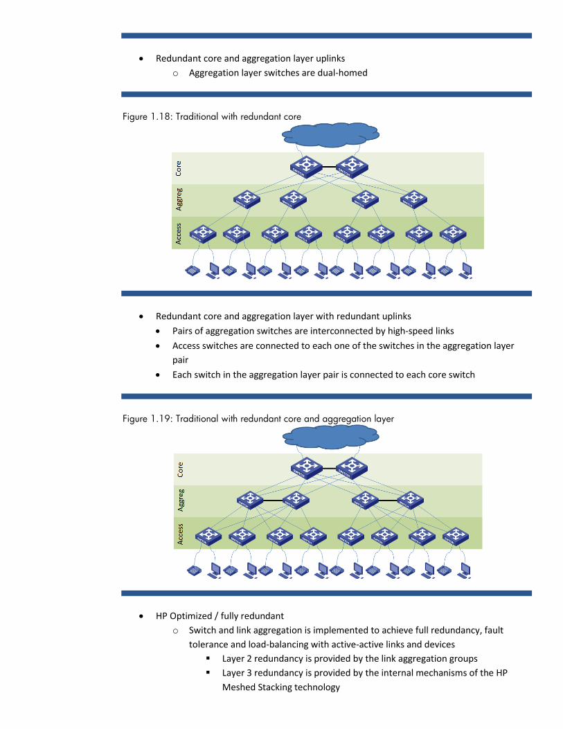
Redundant core and aggregation layer uplinks
o Aggregation layer switches are dual-homed
Figure 1.18: Traditional with redundant core
Redundant core and aggregation layer with redundant uplinks
Pairs of aggregation switches are interconnected by high-speed links
Access switches are connected to each one of the switches in the aggregation layer
pair
Each switch in the aggregation layer pair is connected to each core switch
Figure 1.19: Traditional with redundant core and aggregation layer
HP Optimized / fully redundant
o Switch and link aggregation is implemented to achieve full redundancy, fault
tolerance and load-balancing with active-active links and devices
Layer 2 redundancy is provided by the link aggregation groups
Layer 3 redundancy is provided by the internal mechanisms of the HP
Meshed Stacking technology

Figure 1.20: HP Optimized 3-tier

Logical Infrastructure Models
VLANs
The most common reason to implement VLANs is to control broadcast traffic. In a flat LAN (where all
switches forward according to Layer 2 addresses), broadcasts travel everywhere. In other words, the
whole LAN is a single broadcast domain. This is an important issue, because if broadcasts are, for
example, a (very conservative) 1% of the total traffic, the LAN can be forwarding well over 100Mbps
of broadcasts. These broadcasts will clog smaller links: WLANs, Internet firewall links, client access
links and overloaded servers.
The solution is to divide the LAN into smaller and sometimes dedicated broadcast domains. This was
the purpose of the IEEE 802.1Q standard.
A second reason for VLANs is security: it is simpler to control/filter traffic between VLANs than in a
flat network (see rules number 4 and 6 below).
Examples of some basic rules that can be established are:
1. The number of wired clients per VLAN must be kept below a certain number. This number
will depend on the applications, but it will vary between 100 and 200 workstations.
2. If VoIP/IP Telephony is implemented, a dedicated Voice-VLAN is recommended and all IP
phones, PSTN gateways, etc. must be connected to it. This configuration will prevent the
need for multicast routing in the LAN. One caveat is that this configuration depends on the
number of phones. In a large campus, several voice VLANs can be implemented and
routing between them would be implemented at the core or aggregation layers.
3. If possible, network printers should be in the same VLAN as their clients.
4. Guest clients must be connected automatically to a Guest VLAN that is isolated from the
rest of the network and only provides Hospitality Services that include Internet access. If a
guest VLAN is not configured, then unknown devices must be denied access to the
network.
5. WLAN access points need a VLAN that is not shared with wired clients and servers. Today’s
APs can associate SSIDs to different VLANs and wireless clients with different security
clearance levels can be connected to different VLANs, for example, this feature can be
combined with rule 4 for guest client devices.
6. ACLs, firewalls, IPSs and other security devices and features can be implemented at the
VLAN boundary (VLAN’s L3/routing interface) to enforce protection.
VLAN Implementation
In general, switch ports can be configured to support traffic from 1 or more VLANs. By default, all
ports are configured with a single VLAN (called VLAN 1). When more than one VLAN is configured
in a port, there is a need for a mechanism to distinguish to which VLAN each incoming frame belongs
to. The standard mechanism defined by the IEEE 802.1Q is to tag packets with several fields, one of
which is the VLAN ID.
Port link-types
In HP’s Comware operating system, ports supporting only one VLAN are called Access Link-type ports
or simply access ports and the VLAN supported is called the default VLAN for that port and the PVID
(Port VLAN ID) is the VLAN-ID of the default VLAN. By default, all ports are Access Link-type ports and
their PVID is 1. Ports can also be configured to be Trunk Link-type ports. These ports support traffic
from several VLANs, one of which must be untagged and is the default VLAN (PVID). Finally, some
switches support Hybrid Link-type ports (or simply Hybrid ports). These ports support several untagged
and several tagged VLANs.
Some criteria related to port link-types are:
1. Workstations are connected to access link-type ports

2. Inter-switch links are composed of Trunk Link-type ports where the default VLAN is the
Management VLAN and is used by the network management system to discover and
maintain the network inventory and topology information, and to transport alarms and
events.
3. Hybrid ports can be used in two situations:
a. When there is a need to configure many tagged VLANs and no untagged VLAN, like
in the cases of a link with the other end connected to a switch, server, access
point, or router that supports either tagged or untagged ports but not trunks
b. When there is a need to have more than one untagged VLAN.
4. Servers can be connected either to access, trunk or hybrid link-type ports depending on
the need.
In the case of 3.b, the hybrid port requires additional configuration for it to be able to assign
untagged incoming frames to the right VLANs. For this purpose, special VLAN mechanisms
(sometimes called special VLAN Types) have been defined: protocol-based VLANs, IP-subnet-based
VLANs, and MAC-address-based VLANs.
Figure 1.21: Hybrid Ports and VLAN identification mechanisms
Protocol-based VLAN is a mechanism that uses the IEEE 802.3 header’s Length/Type field to
determine the VLAN the frame belongs to. It is useful when Layer 3 protocols other than IPv4 are used
in the workstation and are required to be directed to a certain VLAN. Examples: SNA, IPX, AppleTalk
and IPv6.
IP-subnet-based VLAN is a mechanism that uses the source IP address and a subnet mask to
determine the VLAN the frame belongs to. It must be used with fixed IP addresses or static DHCP
entries.
MAC-address-based VLAN is a mechanism that uses the source MAC address and a MAC mask
to determine the VLAN the frame belongs to. It can be used to assign devices like IP surveillance
cameras, IP phones, printers to certain VLANs.
IP Routing
A major topic in any network architecture is IP routing/Layer 3 switching and it is tightly related to
VLANs. With just a few exceptions, in the logical architecture there will be a 1 to 1 match between
VLANs and IP subnets.

2-Tier IP Routing Models
In 2-tier physical infrastructures routing can be implemented as:
1. Routing at the core only. In this case, VLANs extend from the core all the way to the client
device.
When this model is implemented on top of a redundant 2-tier LAN where access switches
are dual-homed, a redundancy protocol must be deployed to achieve load-balancing,
resiliency and loop prevention. In a multi-VLAN environment Layer 2 redundancy is
achieved via MSTP and Layer 3 redundancy is provided via VRRP.
The main issue with this approach is the fact that MSTP/VRRP convergence times are too
long for mission critical networks.
2. Routing both at the core and the access layer. A routing protocol is deployed to route
between VLANs. The preferred protocol for this role is OSPF because of its fast
convergence, scalability and load balancing capability.
Figure 1.22: 2-tier IP Routing models
Routing at the Core Routing at the Core and the Access Layer
3-Tier IP Routing Models
In 3-tier infrastructures layer 3 switching can be implemented in three different ways:
1. Routing both at the core and the aggregation layers
2. Routing at the aggregation layer only
3. Routing everywhere
Figure 1.23: 3-tier IP Routing models
Routing at the Core and the Aggregation Layer Routing at the Aggregation Layer
Routing Everywhere

Multicast
Introduction
When planning for multicast traffic management, different parts of the multicast traffic path must be
considered.
Between the source’s and receivers’ gateways, multicast routing must happen. Also, between the last
hop router and the receiver’s multicast group, management must happen. For the first function, PIM-
DM and PIM-SM are the most common solution in today’s private networks. For the latter, IGMP is the
protocol required. When multicast receivers are connected to an L2 switch, then IGMP snooping and
multicast VLAN can be implemented.
IGMP
The first decision to be made is which version of IGMP will be implemented: IGMPv2 or IGMPv3.
IGMPv3 should be used when source-specific multicast is required. This version matches adequately
with PIM-SM. If source-specific multicast is not required, then IGMPv2 is simpler to implement and
maintain. Additionally, not all layer 2 switches support IGMPv3 snooping.
IGMP Querier If there are multiple IPv4 gateways in a receivers’ subnet, two or more routers can be enabled with
IGMP. In any case, only one IGMP querier (Designated Router) can be active at any time. There is no
configuration necessary for this feature to work. If there is a need to force one of these routers to
become the querier, it has to be configured with the smallest IP address in the subnet. IGMP assumes that both queries and reports are received by all stations in the subnet – it is a single
Ethernet collision domain. By default, Ethernet switches are designed to treat multicast traffic as if it
were broadcast. To avoid multicast traffic being flooded, ethernet switches include the IGMP
snooping feature. It is recommended to implement IGMP Snooping wherever Multicast traffic is
expected in a Layer 2 switch.
Multicast VLAN When multiple VLANs are transported between a layer 2 switch and the IGMP querier, and there are
receivers for a multicast group in more than one VLAN, multiple copies of the multicast traffic are
forwarded by the querier.
To avoid this, a Multicast VLAN can be configured in the Layer 2 switch. This feature takes IGMP
reports from a receiver’s VLAN and moves them to the Multicast VLAN. In this way, the IGMP querier
forwards a single multicast flow into this special VLAN. The layer 2 switch then copies this traffic into
each one of the receiver’s VLANs.
Figure 1.24: Multicast VLAN
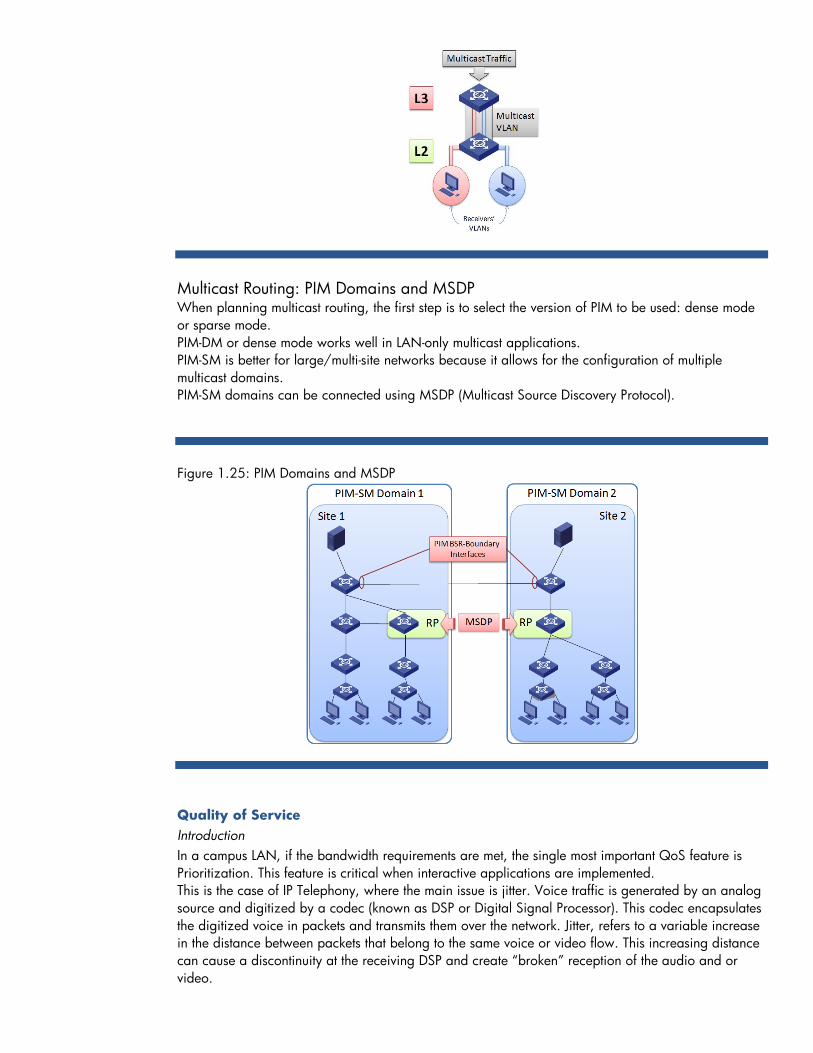
Multicast Routing: PIM Domains and MSDP When planning multicast routing, the first step is to select the version of PIM to be used: dense mode
or sparse mode.
PIM-DM or dense mode works well in LAN-only multicast applications.
PIM-SM is better for large/multi-site networks because it allows for the configuration of multiple
multicast domains.
PIM-SM domains can be connected using MSDP (Multicast Source Discovery Protocol).
Figure 1.25: PIM Domains and MSDP
Quality of Service
Introduction
In a campus LAN, if the bandwidth requirements are met, the single most important QoS feature is
Prioritization. This feature is critical when interactive applications are implemented.
This is the case of IP Telephony, where the main issue is jitter. Voice traffic is generated by an analog
source and digitized by a codec (known as DSP or Digital Signal Processor). This codec encapsulates
the digitized voice in packets and transmits them over the network. Jitter, refers to a variable increase
in the distance between packets that belong to the same voice or video flow. This increasing distance
can cause a discontinuity at the receiving DSP and create ―broken‖ reception of the audio and or
video.
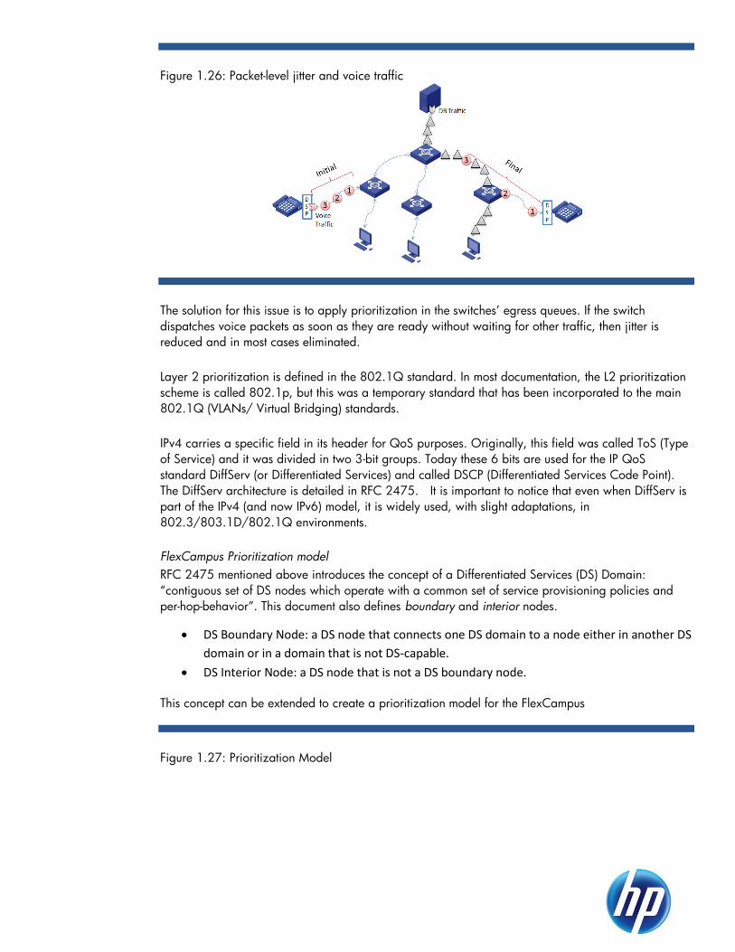
Figure 1.26: Packet-level jitter and voice traffic
The solution for this issue is to apply prioritization in the switches’ egress queues. If the switch
dispatches voice packets as soon as they are ready without waiting for other traffic, then jitter is
reduced and in most cases eliminated.
Layer 2 prioritization Layer 2 prioritization is defined in the 802.1Q standard. In most documentation, the L2 prioritization
scheme is called 802.1p, but this was a temporary standard that has been incorporated to the main
802.1Q (VLANs/ Virtual Bridging) standards.
Layer 3 prioritization IPv4 carries a specific field in its header for QoS purposes. Originally, this field was called ToS (Type
of Service) and it was divided in two 3-bit groups. Today these 6 bits are used for the IP QoS
standard DiffServ (or Differentiated Services) and called DSCP (Differentiated Services Code Point).
The DiffServ architecture is detailed in RFC 2475. It is important to notice that even when DiffServ is
part of the IPv4 (and now IPv6) model, it is widely used, with slight adaptations, in
802.3/803.1D/802.1Q environments.
FlexCampus Prioritization model
RFC 2475 mentioned above introduces the concept of a Differentiated Services (DS) Domain:
―contiguous set of DS nodes which operate with a common set of service provisioning policies and
per-hop-behavior‖. This document also defines boundary and interior nodes.
DS Boundary Node: a DS node that connects one DS domain to a node either in another DS
domain or in a domain that is not DS-capable.
DS Interior Node: a DS node that is not a DS boundary node.
This concept can be extended to create a prioritization model for the FlexCampus
Figure 1.27: Prioritization Model
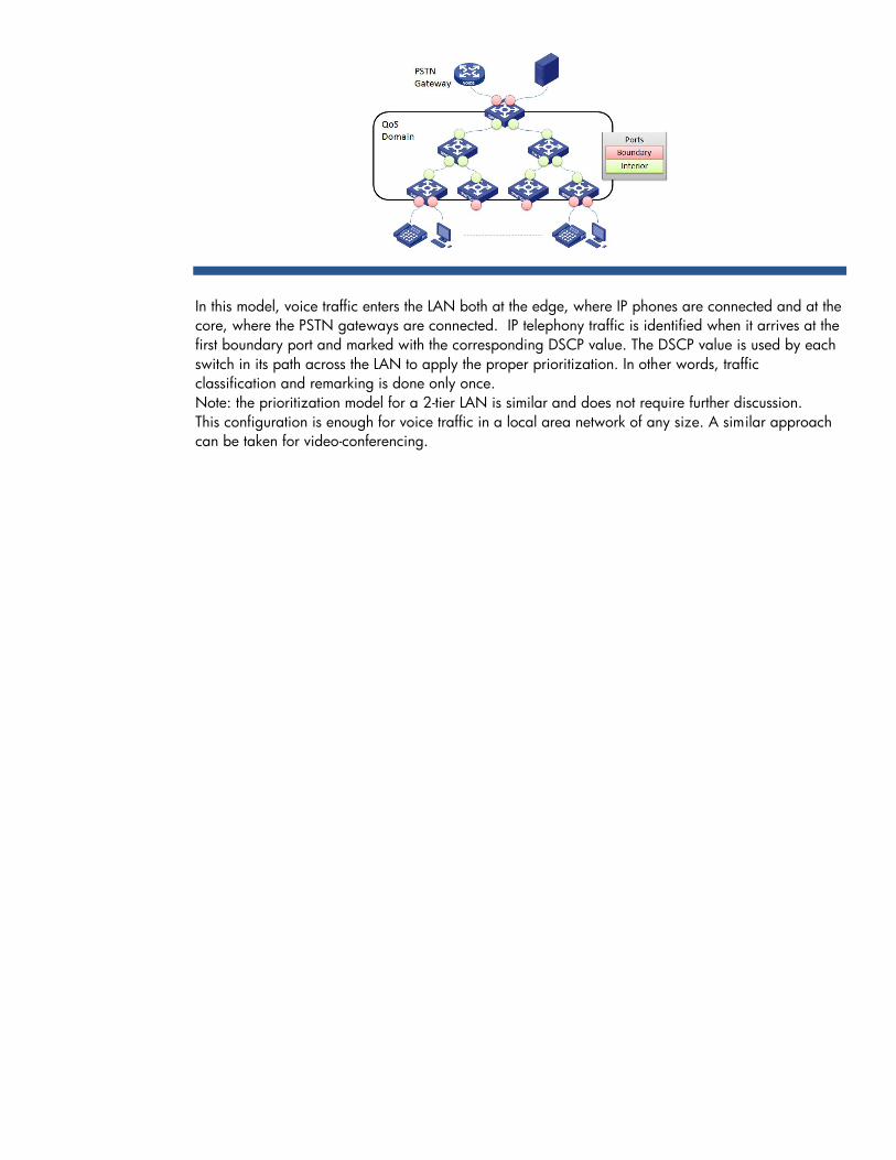
In this model, voice traffic enters the LAN both at the edge, where IP phones are connected and at the
core, where the PSTN gateways are connected. IP telephony traffic is identified when it arrives at the
first boundary port and marked with the corresponding DSCP value. The DSCP value is used by each
switch in its path across the LAN to apply the proper prioritization. In other words, traffic
classification and remarking is done only once.
Note: the prioritization model for a 2-tier LAN is similar and does not require further discussion.
This configuration is enough for voice traffic in a local area network of any size. A similar approach
can be taken for video-conferencing.

FlexCampus Mobility
Wireless Technology Highlights
Designing a wireless network can be a complex process, but meticulous planning and management
will greatly simplify the task and prevent problems in the later phases of deployment. The process
entails assessing a company’s needs, completing an initial site survey, planning radio frequency (RF)
cover- age, installing devices and applying configurations, and then completing the final site survey.
Next, monitoring of the wireless network is required and adjustments can be made to the RF coverage
as needed.
Wireless design is an art not a science.
Wireless Architectures
With the HP MSM devices, one can choose between two architectures:
Autonomous—Includes one or more HP MSM APs.
Optimized WLAN—Includes at least one HP MSM Controller that manages multiple MSM
APs. In the optimized WLAN architecture, the MSM APs are referred to as controlled APs.
Note: In addition to allowing you to manage controlled APs, an MSM Controller can identify
autonomous APs. Typically, however, this would only be done to support third-party APs (which
must be autonomous).
Regardless of architecture choice, multiple Virtual Service Communities (VSCs) can provide wireless
access for users. Each VSC defines settings for one WLAN. By creating multiple VSCs, different
services can be supported for different wireless users.
Autonomous Architecture
In the autonomous architecture, full-featured APs provide wireless coverage for a specific area. These
intelligent edge devices can enforce your company’s access policies, securing wireless
communications through industry-standard authentication and encryption methods. In addition,
autonomous APs can apply sophisticated quality-of-service (QoS) measures and enable Layer 2
roaming (as long as the same VSC is supported in the APs).
Figure 2.3: Autonomous Architecture

Public Access Networks (Centralized Access Control). When a public access VSC is required,
centralized access control must be implemented on that VSC. To implement centralized access control
with an autonomous architecture, one of the following access points is required:
MSM313 AP
MSM313-R AP
MSM323 AP
MSM323-R AP
Note: These products support software version 5.2.x and below. They do not support subsequent
software releases.
At least one AP in the system must be one of these models. The remaining APs can be different
models.
When enforcing centralized access control in an autonomous architecture, each AP is configured and
managed separately. However, all APs forward authentication and user traffic on the public access
VSC to one of the APs listed above, which is configured as the access controller.
The AP acting as an access controller forces wireless users to log in before allowing them to reach
resources beyond its Internet port. (Unauthenticated users can access any resources on the LAN port.)
The access controller authenticates the users either against its local list or an external RADIUS server.
To implement dynamic settings for different users or RADIUS accounting, an external RADIUS server
must be used. However, special settings can be configured for all public users on the local list.
HP recommends that customers update to an MSM710, MSM760, or MSM765zl. This is because
these products do not offer the full range of features that an MSM Controller offers and they will not
be updated in the future.
Optimized WLAN Architecture
The optimized WLAN architecture is exactly what the name implies: an architecture that enables the
implementation of a wireless network so that it is as effective, efficient, and functional as possible in
any situation. The optimized WLAN architecture enables central management of multiple APs with a
controller, which automates deployment and software distribution. The controller also centralizes
device configuration and management. Controlling your APs centrally makes your network scalable,
reducing the complexity of managing (and the time needed to manage) your wireless network.
Figure 2.2: Optimized WLAN Architecture
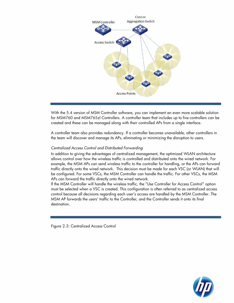
With the 5.4 version of MSM Controller software, you can implement an even more scalable solution
for MSM760 and MSM765zl Controllers. A controller team that includes up to five controllers can be
created and these can be managed along with their controlled APs from a single interface.
A controller team also provides redundancy. If a controller becomes unavailable, other controllers in
the team will discover and manage its APs, eliminating or minimizing the disruption to users.
Centralized Access Control and Distributed Forwarding
In addition to giving the advantages of centralized management, the optimized WLAN architecture
allows control over how the wireless traffic is controlled and distributed onto the wired network. For
example, the MSM APs can send wireless traffic to the controller for handling, or the APs can forward
traffic directly onto the wired network. This decision must be made for each VSC (or WLAN) that will
be configured. For some VSCs, the MSM Controller can handle the traffic. For other VSCs, the MSM
APs can forward the traffic directly onto the wired network.
If the MSM Controller will handle the wireless traffic, the ―Use Controller for Access Control‖ option
must be selected when a VSC is created. This configuration is often referred to as centralized access
control because all decisions regarding each user’s access are handled by the MSM Controller. The
MSM AP forwards the users’ traffic to the Controller, and the Controller sends it onto its final
destination.
Figure 2.3: Centralized Access Control

One of the main reasons to implement centralized access control on a VSC is to create a public
access VSC, in which users must authenticate through a Web login page before they can access the
protected network. Centralized access control enables the controller to act as the gatekeeper to the
wired network, enforcing access controls on all wireless user traffic in this VSC.
Centralized access control also benefits networks that require a large coverage area but have a
limited infrastructure. This is accomplished by providing an integrated firewall, Dynamic Host
Configuration Protocol (DHCP) server, and RADIUS server for wireless traffic. The downside to
centralized access control is that the controller processes 100 percent of the wireless user traffic in
that VSC. The wireless network thus has a single point of failure, and the traffic detour to the controller
adds latency and traffic on the wired network. In addition, if you are using 802.11n, an evaluation
whether or not a single controller with its single uplink can handle the throughput may be required.
Determine if the controller must handle a high volume of guest traffic and how much delay guests can
tolerate.
Although centralized access control solves many problems associated with giving guests wireless
access, it is not usually necessary for VSCs used by employees. When wireless access is setup for
employees, typically they will want the same access or nearly the same resources that are available to
them through a wired connection. For these VSCs, intelligent APs will be needed to forward wireless
traffic directly onto the wired network. This distributed forwarding approach allows performance to be
easily scaled by combining the benefits of centralized management with the benefits of intelligent APs
at the edge. (See Figure 1-6.)
The distributed forwarding approach is ideal for 802.11n deployments, in which high-speed wireless
connectivity generates a great deal of traffic. Because each AP forwards traffic independently, the
traffic is distributed across multiple points. The wired network more easily handles the additional
traffic, and users experience the full benefit of 802.11n.
Figure 2.4: Distributed Forwarding

With distributed forwarding, there is also an option to use centralized authentication. With
centralized authentication, APs forward all traffic related to the authentication process to the controller
for handling. In other words, the controller acts as the authenticator in the 802.1X process. The MSM
AP continues to handle the wireless data traffic, transmitting it directly onto the wired network.
Centralized authentication may be implemented under the following circumstances:
The controller’s internal RADIUS database is used to authenticate users.
Simplified configuration of the clients on the RADIUS server is desired. If the controller is
the only RADIUS client for wireless traffic, only one client for the wireless network on the
RADIUS server needs to be configured.
Although the MSM APs are sending only authentication traffic (which is a relatively small amount)
to the MSM Controller, the impact of the traffic must still be evaluated. For example, how will the
authentication traffic affect traffic flow on the wired network?
Figure 2.5: Distributed Forwarding with Centralized Authentication
Architecture Comparison
The advantages and disadvantages of each approach for forwarding traffic are summarized in the
following table.

Table 2.1: Advantages and disadvantages of the architectures
Approach Advantages Disadvantages
Centralized
Access
Control
Effective coverage of large areas
Centralized management of APs
with a controller
An integrated firewall, DHCP
server, and RADIUS server for
wireless traffic (ideal for networks
that have a limited infrastructure)
Authentication and access control
for the wireless network
independent of the wired network
Dynamic meshing across a work
space
Controller must process 100
percent of the network traffic,
creating single point of failure
Designed to handle the throughput
associated with 802.11a/g
standards, it cannot easily address
the increased performance that
comes with
802.11n
No failover mechanism if controller
fails
Separate authentication and access
control for the wireless network
Distributed
Forwarding
Effective coverage of large areas
Centralized management of APs
with a controller
Use of the existing corporate
network access control system
Dynamic meshing across a work
space
Non-blocking architecture capable
of delivering full throughput with
802.11n APs
Optional use of the MSM Controller
internal RADIUS server (the
centralized authentication option)
No public access network (Web-
Auth)
No integrated firewall for wireless
traffic
With the optimized WLAN architecture, both centralized access control and distributed forwarding
can be used on the same MSM Controller. This means that the appropriate access control can be
applied for each group of users and control how traffic is sent onto the wired network.
Combining Autonomous and Optimized WLAN Architectures
When deploying MSM APs, you might use different architectures for different parts of your network
that have different characteristics. For instance, a large main office might have an optimized WLAN
architecture that uses distributed forwarding for employee VSCs and centralized access control for
guest VSCs. However, the organization may also have a branch office that is using a couple of MSM
APs in an autonomous architecture.

FlexCampus Network Management
Single pane-of-glass network management
With FlexCampus, enterprises can count on a common operating experience across all network
segments from access to core. HP’s Intelligent Management Center (IMC) manages over 5700
network devices from 150 different manufacturers, enabling IT to seamlessly manage heterogeneous
networks and help ease the migration to best-in-class network solutions. IMC not only bridges the gap
between wired and wireless network management, but also between physical and virtual network
management.
For granular network and application access, IMC manages user access control and identity-based
policies to not only make sure enterprises know who is on their network but what they’re doing when
connected. The result is that IMC speeds application and service delivery, simplifies operations and
management, and boosts network availability and security.
IMC offers the following benefits:
Lower operating expenses and improved total cost of ownership, because of automated
features, default alerts, and a consolidation of tools and correlated information
Improved network availability and reliability that result in fewer trouble tickets, thanks to
automated configuration management and comprehensive auditing
Quicker problem recognition and troubleshooting
Improved endpoint defense, control, and visibility
Integrated management between wired and wireless networks, and even physical and
virtual networks
Excellent flexibility and scalability for networks of all sizes
Multi-vendor support
HP IMC Features
IMC’s base system components and add-on modules aligns with all areas of the ISO
Telecommunications Management Network’s highly regarded FCAPS model (for Fault, Configuration,
Accounting, Performance, and Security).
Figure 3.1: IMC features map directly to the FCAPS model

The IMC Base Platform and Service Modules
Intelligent Management Center (IMC) is a comprehensive solution for the management of advanced
enterprise networks. IMC was built from the ground up to support FCAPS (Fault, Capacity, Asset
Management and Auditing, Performance, and Security management), a standard model for
addressing the management needs of enterprise networks. Ideal for large enterprise IT and data
center environments, IMC uses a service-oriented architecture (SOA) model to deliver full and
extensible device, service and user management functionality. IMC also ensures performance and
scalability through distributed and hierarchical deployment models and through variable options for
operating system and database support. IMC’s modular design enables IMC to integrate traditionally
separate management tools into a single unified platform.
IMC as a whole consists of a base platform for delivering network resource management capabilities
and optional service modules for extending IMC’s functionality. The base platform provides
administrators and operators with the basic and advanced functionality needed to manage IMC and
the devices, users, and services managed by IMC. The base platform incorporates the essential
functional areas of network management – fault, configuration, asset management and auditing,
performance, and security. The optional service modules enable administrators to extend and
integrate the management of voice, wireless, and MPLS VPN networks as well as end user access and
endpoint defense management into IMC for a unified element management platform. The IMC base
platform provides the following:
• Resource Management including network device management from the SNMP, Telnet, and
SSH configurations on a device to Spanning Tree configurations and PoE energy
management and more.
• Configuration and change management for device configurations and system software files
for devices managed by IMC. This includes storing, backing up, baselining, comparing, and
deploying configuration and software files.
• Real-time management of events and the translation of events into faults and alarms in IMC.
This includes creating, managing, and maintaining alarm lists, trap and Syslog filters and
definitions, and configurations for notifications of alarms.
• Monitoring, reporting, and alarming on the performance of network resources. This includes
managing global and device specific monitors and thresholds as well as creating views and
reports for displaying performance information.
• Managing access control list (ACL) resources including creating and maintaining ACL
templates, resources, and rule sets and deploying ACL rule sets to devices managed by IMC.
It also includes monitoring and leveraging ACLs that exist on devices for deployment to other
network devices.
• Monitoring and managing security attacks and the alarms they generate.
• Global management of VLANs for all devices managed by IMC that support VLANs.

• Administrative controls for managing IMC and access to it through operator and operator
group management, system-wide management of device data collection and information
shared by all IMC modules including the creation and maintenance of device, user, and
service groups and device vendor, series and device model information. It also includes
SNMP MIB management and other system-wide settings and functions.
In addition, IMC also includes service modules for extending and unifying its network management
capabilities. IMC service modules include the following optional service modules:
• Wireless Service Manager (WSM): The WSM service module integrates the
management of wired and wireless networks. With WSM, operators can perform wireless
LAN (WLAN) device configuration, view topology maps of the wireless network, monitor
performance, manage RF coverage and planning, implement WLAN intrusion detection and
defense, and generate WLAN service reports from the same platform used to manage wired
networks. WSM also provides fault and performance monitoring, reporting, and alarming for
the wireless infrastructure.
• Voice Services Manager (VSM): Voice Service Manager (VSM) module integrates voice
services management into IMC for managing converged voice and data networks. VSM
provides voice service management for 3Com and H3C voice infrastructures, including
VCX® Connect platforms, Media Gateway and IP phones. VSM also provides management
and notification of issues that may impact service quality. VSM monitors the voice network
using built-in rules and will diagnose problems, track changes to IP phone status, and track
inventory of communications devices and IP phones. VSM also provides tools to facilitate
troubleshooting and fault isolation as well as real time service-level, alerting and reporting.
• User Access Manager (UAM): UAM works in conjunction with the iNode client and EAD
to provide endpoint network access control, policy enforcement, quarantine, and a captive
portal for ensuring the security of the network infrastructure. UAM delivers the user
authentication, authorization and authorization services and supports access policies across a
variety of access devices such as Ethernet switches, routers, broadband access servers and
VPN access gateways to centrally manage access for wired, wireless, and remote users.
• Endpoint Admission Defense (EAD): IMC’s Endpoint Admission Defense (EAD) module
is an optional component of IMC that works in conjunction with UAM and the iNode client to
provide endpoint security. At the core of EAD are its security policy features that enable
administrators to control endpoint admission based on the identity and posture of the
endpoint. If an endpoint is not compliant with required software packages and updates, EAD
will block or isolate an endpoint’s access to protect network assets. EAD’s security policy
component also provides non-intrusive actions to proactively secure the network edge
including endpoint monitoring and notification. EAD also supports security evaluation,
security threat location and security event awareness. EAD also identifies endpoint patch
levels, virus engine and definition file versions, Address Resolution Protocol (ARP) attacks,
abnormal traffic, the installation and running of sensitive applications and status of system
services to minimize the risk of malicious code infections. To ensure continued security, EAD
provides continual monitoring of endpoint traffic, installed software, running processes and
registry changes. These functions ensure that all endpoints connected to the network are
secure and thus that the network is secure.
• Network Traffic Analyzer (NTA): Network Traffic Analyzer (NTA) integrates network
Layer 4-7 monitoring into IMC’s network management platform. NTA leverages the
instrumentation (Netflow, NetStream, sFlow) already available in network devices such as

routers and switches to provide reporting on network resource usage. With NTA,
administrators can tailor NTA’s data collection and reporting capabilities to meet specific
reporting requirements and view NTA’s reports directly from IMC’s integrated platform. NTA
provides thresholds for alarm generation and notification when problems are detected by
NTA.
• User Behavior Auditor (UBA): UBA provides network administrators with visibility into
user behavior for web sites, specific URLs, email sender or receiver addresses, database
access and operations, file transfers, and FTP access. When used in conjunction with the User
Access Manager (UAM) service module, UBA also provides user behavior auditing by user
name and IP address. UBA provides this visibility by analyzing data from many sources
including network address translation (NAT) records, NetStream, Flow and sFlow records,
and DIG probe logs.
• Quality of Service Manager (QoSM): Quality of Service Manager (QoSM) integrates
quality of service (QoS) management into IMC, providing a single platform for viewing and
managing the configuration, deployment, and optimization of QoS configurations. QoSM
provides administrators with features for managing the configuration of QoS enabled devices
in the network including the ability to automatically discover existing QoS devices and
configurations and standardize QoS configurations. QoSM also provides administrators with
QoS analysis and optimization features for measuring the effectiveness of a QoS deployment
as well as recommendations for optimizing QoS deployments.
• MPLS VPN Manager (MVM): MPLS VPN Manager (MVM) integrates MPLS VPN
management into IMC, providing a single platform for viewing and managing the
configuration, deployment, and management of MPLS VPN configurations. MVM provides
administrators with features for managing the configuration of MPLS VPN devices in the
network including the ability to automatically discover existing VPN configurations, PE and
CE device management, AS and area management, VPN, and SC management. MVM also
provides fault and performance monitoring, reporting, and alarming for the wireless
infrastructure.
HP IMC Base Platform Deployment Options
Two deployment models are available for the IMC base platform: centralized and hierarchical. For
IMC deployments that include service modules, please refer to the sections of this guide that address
deployment options for the service modules you want to deploy.
Centralized Deployment
A centralized deployment of IMC is ideal for infrastructures that have a small number of nodes to be
managed, all of which can be found in a single location. In a centralized deployment, the IMC base
platform is installed on a single server. The IMC database may be installed on the same server as the
base platform or it may be installed on a remote server. Operators access all IMC functionality
including alarms and performance reporting from the IMC base platform.
Figure 3.2: Centralized Deployment with embedded DB
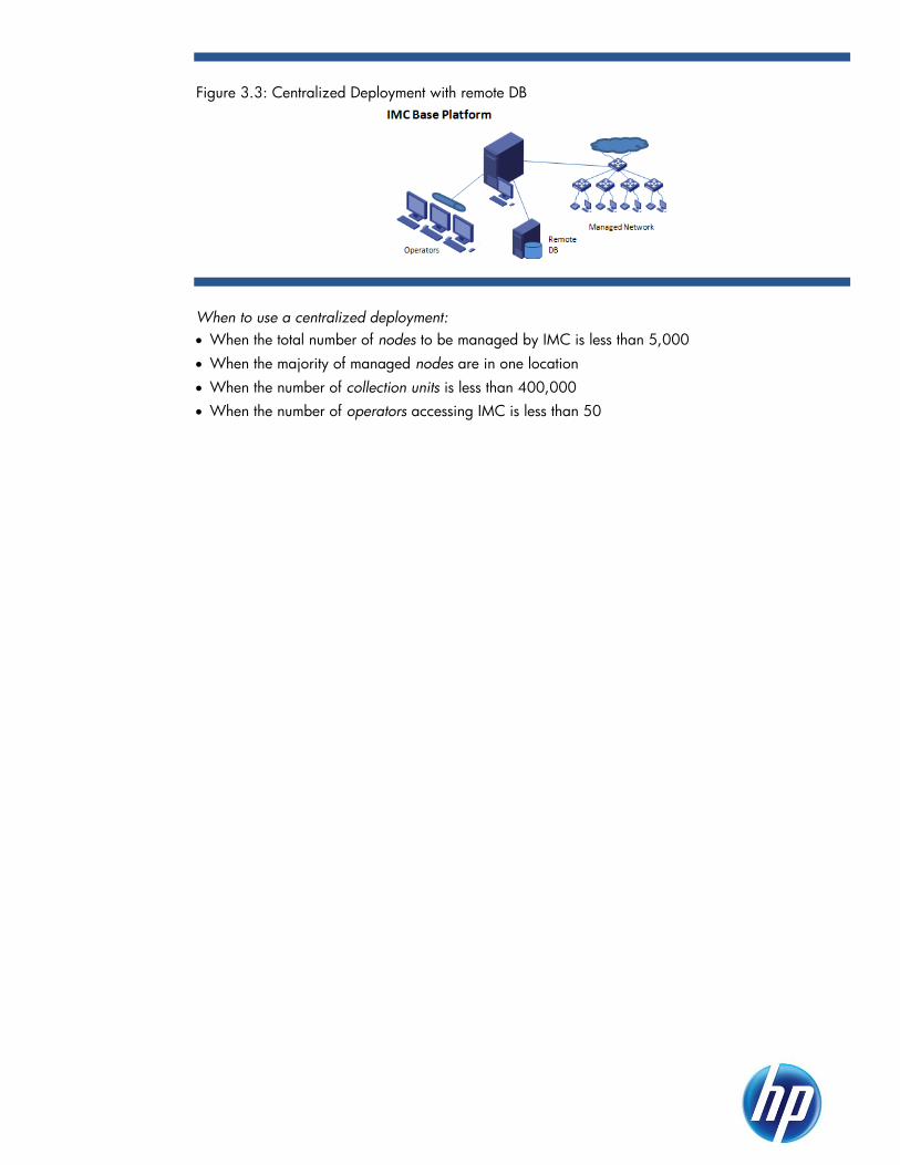
Figure 3.3: Centralized Deployment with remote DB
When to use a centralized deployment:
When the total number of nodes to be managed by IMC is less than 5,000
When the majority of managed nodes are in one location
When the number of collection units is less than 400,000
When the number of operators accessing IMC is less than 50

Hierarchical Deployment
A hierarchical deployment of IMC addresses the need for managing network nodes that are
geographically dispersed or for managing a large number of network nodes in a single location or in
multiple locations. In a hierarchical deployment, multiple IMC base platforms are deployed. The
databases for each base platform may be installed on the same server as the base platform or may
be installed on a remote server. In this deployment model, one IMC base platform operates and
communicates as a parent between all other child IMC base platform servers. Operators access the
full functionality of the base platform by connecting directly to the individual base platform server.
Performance and fault data however can be rolled up to the parent IMC base platform server, if
desired.
Figure 3.4: Hierarchical Deployment
When to use a hierarchical deployment:
When the total number of nodes managed by IMC exceeds 5,000 or
When the nodes to be managed are located in multiple, geographically dispersed locations
When the operators using IMC are geographically dispersed
When the number of collection units exceeds 400,000
When the number of operators accessing IMC exceeds 50
HP IMC Add-on Modules Deployment Options
Add-on modules support several deployment options that can be combined with the base platform’s
options
Table 3.1: Deployment Options
In a centralized deployment, the NTA service module is installed on the IMC base platform. The IMC
database may be installed on the same server as the base platform or may be installed on a remote
server and is still considered a centralized deployment. The database for NTA can also be installed
on the base platform or on a remote server. An optional Dig server can be used to receive network
traffic and translate into network flow records for NTA processing. A Dig server must be installed on a
dedicated server.
In a distributed deployment, the IMC base platform is installed on a single server and the add-on
service module is installed on a separate, local server. The IMC database may be installed on the
same server as the base platform or may be installed a remote server. The database for the add-on
may be installed on the add-on server or on a remote server. In this deployment model, the IMC base
platform operates and communicates as a master to the distributed add-on slave server on which the
service modules run. Operators access the add-on’s functionality through the master IMC base
platform.
In a hierarchical deployment of an add-on module, multiple IMC base platforms are installed on
separate servers. One or more add-on service modules are installed on one or more of the existing
IMC base platform servers. The databases for every IMC instance may be installed on the same server
as the base platform or may be installed a remote server. The database for every instance of add-on
may be installed on a remote server. In this deployment model, one IMC base platform server
operates and communicates as a parent to the child IMC instances and to the add-on module
instances running on them. Operators access add-on’s functionality through the IMC servers upon
which the add-on is installed. Alarms and performance reporting for all child IMC instances and add-
on service modules can be rolled up to the single parent IMC base platform.
Finally, in a hybrid deployment of an add-on module, multiple IMC base platforms are deployed. One
or more add-on service modules are deployed each on a dedicated server that is local to an IMC
base platform. Or, add-on service modules may also be installed on the base platform servers. The
databases for every IMC instance may be installed on the same server as the base platform or may
be installed a remote server. The database for every instance of an add-on service may be installed
on the server or on a remote server. In this deployment model, one IMC base platform operates and
communicates as a parent to all child IMC instances. If an add-on service module is installed on an
IMC base platform, operators will access add-on functionality from the IMC base platform upon which
it is installed. If an add-on service module is installed on a dedicated server, this server operates as a
slave to the master IMC base platform instance local to it and operators access add-on’s functionality
through the local master IMC base platform server. Alarms and performance reporting for all child
IMC instances and slave add-on servers can be rolled up to the single parent IMC base platform.
Note that an IMC base platform instance can operate as a child to a parent IMC server and serve as
a master IMC server to a slave server running one or more service modules.
FlexCampus Security
Overview
In the past, network security was an afterthought and laid on top of a network and then usually only
at the perimeter. That was a time when internal employees and contractors were believed to be
trustworthy. However, recent insider attacks have proven that employees cannot be trusted. We are
also seeing more personal devices on corporate networks that can lead to malware introduction on a
larger scale.
Network administrators must now assume that no one can be trusted and are starting to build
networks based on a zero trust model. This leads to the need to build security into a network from the
ground up. From a high level, there are two parts to network security. The first is Access Control and
is used to deny unauthorized access and permit access only to those resources that are needed. After
access has been granted, it is necessary to continuously monitor user and device behavior and detect
and block inappropriate behavior.
Access control can be accomplished in three ways: 802.1X, Web Portal Authentication, and MAC
Authentication. These methods can be used to identify a user / device and then access control lists
can be applied to permit access to only those resources that are needed to accomplish a job. The
three options are listed from most difficult to deploy to easiest, while at the same time being most
secure to least secure. There is an added layer available to validate that a device is fully patched, is
running required software, etc. called Endpoint Integrity validation or posture checking. Endpoint
Integrity validation is useful to ensure that devices have known vulnerabilities patched, enabled
firewalls, and up to date virus definitions in addition to numerous other options. Resource access
control can be accomplished in two main ways. The first is to apply ACLs, Access Control Lists, to
router interfaces at the edge of a VLAN and then to assign users subject to those controls to that
VLAN. The other option is to assign ACLs per user at the edge of the network where the user
connects.
Once a user or device authenticates and meets a company’s posture requirements, they are permitted
the appropriate resources. At this point it is necessary to monitor the activity of that user/device for
inappropriate behavior. This is accomplished with Intrusion Detection/Prevention devices. There are
two main types of IDS/IPS devices, inline and distributed. A TippingPoint IPS is an inline device.
These devices utilize vulnerability signatures as well as anomaly engines to detect inappropriate
behavior. Signature-based detection is considered to be very accurate and if done correctly will lead
to very low false positive and false negative events. However, anomaly detection is more prone to
false positive and negative detection. An example of a distributed IDS/IPS solution is using sFlow
traffic samples to look for anomalous behavior. While a detected anomaly may not be considered
certain enough to act upon, it can lead to further inspection. The advantage of a distributed solution is
that detection can be made anywhere in a network where it would be too expensive to deploy an
inline IPS at every location. A good solution would be to deploy both solutions as complements to
each other.
The solutions and technologies discussed above assume that the network they are deployed on is
secure, and called a Trusted Infrastructure. A Trusted Infrastructure is accomplished by configuring the
network to deny unauthorized configuration and topology changes. In its most basic form, this means
setting secure passwords on all infrastructure devices but can be enhanced by implementing a central
authentication system based on RADIUS and using encrypted management protocols, such as SSH,
SSL/HTTPS, and SNMPv3. Beyond securing management access to the networking devices, it is also
necessary to add protection to inherently insecure network protocols, such as ARP, DHCP and
Spanning Tree.
To summarize, network security is a solution of various components built upon a Trusted Infrastructure.
There is not one single device or technology that will secure a network. Security requires a Defense-In-
Depth approach. The solution then follows the user. First a user is authenticated and validated to be
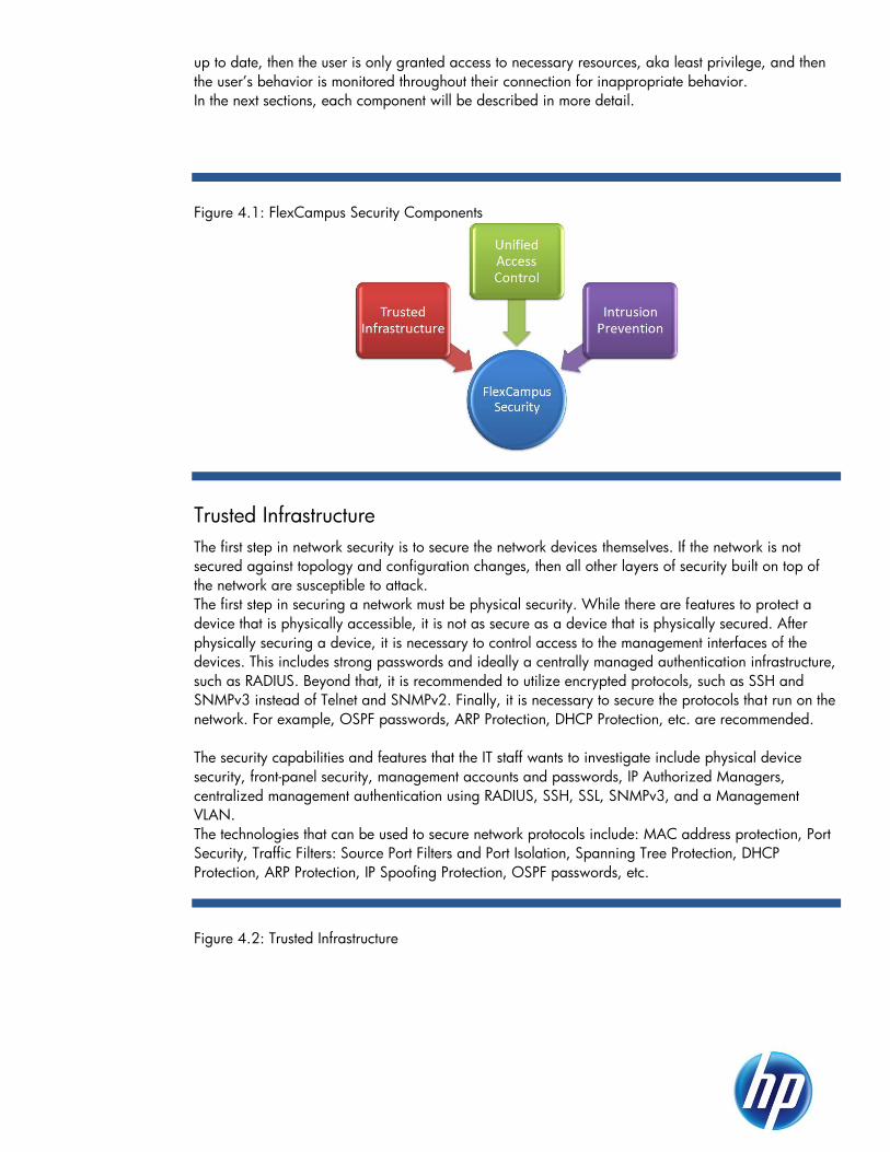
up to date, then the user is only granted access to necessary resources, aka least privilege, and then
the user’s behavior is monitored throughout their connection for inappropriate behavior.
In the next sections, each component will be described in more detail.
Figure 4.1: FlexCampus Security Components
Trusted Infrastructure
The first step in network security is to secure the network devices themselves. If the network is not
secured against topology and configuration changes, then all other layers of security built on top of
the network are susceptible to attack.
The first step in securing a network must be physical security. While there are features to protect a
device that is physically accessible, it is not as secure as a device that is physically secured. After
physically securing a device, it is necessary to control access to the management interfaces of the
devices. This includes strong passwords and ideally a centrally managed authentication infrastructure,
such as RADIUS. Beyond that, it is recommended to utilize encrypted protocols, such as SSH and
SNMPv3 instead of Telnet and SNMPv2. Finally, it is necessary to secure the protocols that run on the
network. For example, OSPF passwords, ARP Protection, DHCP Protection, etc. are recommended.
The security capabilities and features that the IT staff wants to investigate include physical device
security, front-panel security, management accounts and passwords, IP Authorized Managers,
centralized management authentication using RADIUS, SSH, SSL, SNMPv3, and a Management
VLAN.
The technologies that can be used to secure network protocols include: MAC address protection, Port
Security, Traffic Filters: Source Port Filters and Port Isolation, Spanning Tree Protection, DHCP
Protection, ARP Protection, IP Spoofing Protection, OSPF passwords, etc.
Figure 4.2: Trusted Infrastructure

Management features: The recommended management protocols: SSH, SSL, SNMPv3, and SFTP
are encrypted protocols and help with privacy and authenticity. Front panel security allows an
administrator to disable the password clear and factory reset buttons on the front of a switch. These
features are really useful when a device isn’t physically secured. IP authorized managers and
management ACLs are used to deny access to the device except from specified IP addresses. A
Management VLAN can be used to further secure access to the device management as that VLAN is
usually not routed to other VLANs and requires that a management station be on the Management
VLAN. Finally, a central authentication infrastructure, RADIUS, is recommended so that usernames
and passwords do not have to be shared and for accounting and auditing.
MAC Lockdown and MAC Lockout: These two features provide a type of port-based security.
Both involve the specification of MAC addresses as part of their configuration. Whereas, MAC
Lockdown is used to ensure a particular device can only access the network through designated ports,
MAC Lockout is used to ensure a particular device does not access the network through one or more
switches.
Port Security: This feature enables you to configure each switch port with a unique list of device
MAC addresses that are authorized to access the network through that port. This enables individual
ports to detect, prevent, and log attempts by unauthorized devices to communicate through the switch.
The closest feature to ProVision Port Security on a Comware device is the max MAC address feature.
Layer 2 traffic filters: In the case of both ProVision and Comware software, traffic can be
controlled based on source and destination port.
Spanning Tree Protection: This feature is used to protect against a rouge device being inserted
into the network and causing topology changes and service interruptions. The specific features are:
BPDU Filtering, BDPU Protection, Root Guard, and TCN Guard.
DHCP Protection: DHCP is designed to work in the trusted internal network and does not provide
authentication or access controls. Because of this lack of built-in security, a DHCP server has no way
of verifying that the client requesting an address is a legitimate client on the network. Similarly, the
DHCP client has no way of knowing if the DHCP server that offers it an address is a legitimate server.
Therefore, DHCP is vulnerable to attacks from both rogue clients and servers.
There are two types of common DHCP attacks from which you should protect your network:
Address spoofing—A rogue DHCP server on the network can assign invalid IP addressing information to client devices. This includes the IP addresses of the client itself, the default gateway, DNS servers, and WINS servers. Without valid IP addresses, the legitimate client devices are unable to contact other legitimate IP network devices and users are prevented from reaching the resources they need to do their jobs.

Address exhaustion—An attacker can access the network and request IP addresses until the DHCP server’s supply of available IP addresses is exhausted. This prevents legitimate clients from receiving IP addresses and accessing the network.
Both of these attacks can disrupt network service and cause security breaches.
ARP Protection: ARP is used to resolve a device’s IP address to its MAC address. ARP creates and
populates a table of known IP addresses and the associated MAC addresses as it requests
information for unknown MAC addresses. Most ARP devices update their tables every time they
receive an ARP packet even if they did not request the information. This makes ARP vulnerable to
attacks such as ARP poisoning, ARP snooping, and DoS.
ARP poisoning occurs when an unauthorized device forges an illegitimate ARP response, and other
devices use the response to change their ARP tables. In the example shown here:
Device A broadcasts a request for device B’s MAC address.
Device C, the intruder, responds by matching device B’s IP address to device C’s
MAC address.
At the same time, device C sends a packet to device B, posing as device A. Any
response intended for device B, the legitimate owner of the IP address, now goes
astray to device C.
When device A updates its ARP table with the spoofed entry, device A’s ARP table is
considered ―poisoned‖. Because device B’s IP address is matched with device C’s
MAC address, all IP traffic that device A wants to send to device B is sent to device
C instead.
By positioning itself using a traditional ―man-in-the-middle‖ style attack, device C can capture
information such as usernames and passwords, email messages, and other confidential company
information.
ARP poisoning can also take the form of unsolicited ARP responses and can lead to DoS attacks. For
example, device C can poison other devices’ ARP tables by associating the network gateway’s IP
address with the MAC address of some endpoint station. Because the endpoint station does not have
access to outside networks, outgoing traffic is prevented from leaving the network. The endpoint
station may also become easily overwhelmed by the unexpected traffic.
IP Spoofing Protection: Many network attacks occur when an attacker injects packets with forged
IP source addresses into the network. Also, some network services use the IP source address as a
component in their authentication schemes. For example, the BSD ―r‖ protocols (rlogin, rcp, rsh) rely
on the IP source address for packet authentication. SNMPv1 and SNMPv2c also frequently use
authorized IP address lists to limit management access. An attacker that is able to send traffic that
appears to originate from an authorized IP source address may gain access to network services for
which he is not authorized.
ProVision switches provide a feature called Dynamic IP Lockdown that provides protection against IP
source address spoofing by means of IP-level port security. IP packets received on a port enabled for
dynamic IP lockdown are only forwarded if they contain a known IP source address and MAC
address binding for the port.
Dynamic IP lockdown uses information collected in the DHCP Snooping lease database and through
statically configured IP source bindings to create internal, per-port lists. The internal lists are

dynamically created from known IP-to-MAC address bindings to filter VLAN traffic on both the source
IP address and source MAC address.
Comware switches provide a feature called IP Source Guard that can help to mitigate an IP spoofing
attack. The IP Source Guard function can be enabled on user access ports of the switch to improve
network security. It prevents illegal packets from traveling through the ports. When a port enabled
with the IP Source Guard function receives a packet, the port looks up the key attributes (including IP
address, MAC address and VLAN tag) of the packet in the binding entries of the IP source guard. If
there is a match, the port forwards the packet. If there is no match, the port discards the packet. IP
source guard bindings are on a per-port basis. After a binding entry is configured on a port, it is
effective only on that port.
To implement the management security features, all that is necessary is a RADIUS infrastructure and a
supporting client/application. The features themselves are configured locally and do not
interoperate/depend on with other network devices.
Deployment is a simple configuration assuming a RADIUS infrastructure is available. HP recommends
that all insecure management protocols be disabled, including Telnet, TFTP, HTTP, and SNMPv1/2.
Use SSH, SFTP, HTTPS (SSL), and SNMPv3. Then configure each to authenticate to a RADIUS server
as a primary authentication method with no backup, except for the console port, which must use the
locally configured passwords as a backup. For maximium security, the local operator and manager
accounts should have unique usernames and passwords for each device. These are only used if the
RADIUS infrastructure is unavailable. Then, at a minimum, Spanning Tree, DHCP, and ARP Protection
should be enabled to protect these insecure protocols. The other security features should be
considered as needed.
Unified Access Control
Introduction
Securing a LAN network infrastructure is no easy task. Factors such as cost, network instability, risk of
breach, and ease of implementation all play an equal part in making the right decision to secure a
LAN. In some cases the necessary capabilities are already available built in to your last LAN refresh
to make the network more secure? Take for example IEEE 802.1X, originally specified in 2001.
Although still a relatively new protocol, it has been around for a while, fueled greatly by its
predominant role in securing wireless networks. 802.1X has also been shipping with HP switching
products for several years, now and an increasing number of customers are recognizing the
importance of both protected and differentiated access to a vital and sustaining piece of their
business—the network.
―My network devices are all in secure locations locked away behind our firewall. What additional
security do I need to provide?‖ Someone once said that the only way to truly secure your servers was
to unplug them from the network. With the proliferation of the Internet and e-commerce, our private
networks are not so private anymore. Breaches and denial of service attacks are commonplace and
providing unfettered access to anyone who plugs into an RJ-45 jack is an absolute risk to your
business. A single point of entry and sometime is all that are needed for a malicious user to gain
unauthorized access to information or to deny service to authorized users.
How can the network be defended against a malicious user or a disgruntled employee? Is there
adequate protection for network looping? Any public areas that offer access to the network pose a
threat to its overall health. Even the private areas of the network are constantly at risk from employees
within the trusted network.
Identification through authentication, authorization, and accounting along with network segmentation
are the best ways to provide access without giving away the keys to the kingdom. Implementing
Access Control will not solve every problem, but just as securing a house by locking doors and gates
will not necessarily stop a burglar from entering, it may cause the burglar to give up and move to

another house. In the same way, the more layers of security that can be added to the network, the
better it may defend against attacks.
Problem statement section
The adoption of the IEEE 802.1X protocol and other authentication methods on wired networks has
been relatively slow when compared with wireless networks. One reason offered is the complexity of
getting all of the many pieces working together correctly. For example, for a successful 802.1X
authentication, you need a special piece of client software called a supplicant, a physical point of
attachment that has 802.1X processing capabilities, and an authentication server to authorize the
request. There are many choices of client and server software and a vast collection of authentication
protocols to choose from.
Another reason is the variety of devices and how they attach to the network—VoIP phones, printers,
kiosks, laptops and PDAs can be either mobile or stationary. The network endpoint may or may not
support IEEE 802.1X or provide a way for a user to interactively provide login credentials, so a
holistic approach is needed when the decision is made to authenticate every networked port on the
LAN.
Technical overview and design concepts
Figure 4.3: Unified Access Control
Any discussion regarding secure best practices for the LAN needs to start with three central concepts,
collectively referred to as AAA. ―Triple A‖—authentication, authorization, and accounting
(auditing)—are the main security concepts to consider when implementing access control security on
the network. You not only want to provide access to those who need it, but also to limit the level of
access and be able to monitor it.
Authentication establishes that an entity or subject is the identity that it claims to be. The entity could
be a network endpoint such as a laptop, a printer, or a VoIP phone. Or the entity could be a user that
needs to authenticate in order to use the network’s resources such as email and file sharing.
Authentication, in its simplest form, is established by the entity presenting a username and password
to the authentication server, which validates these credentials against a stored database such as
Active Directory or LDAP. This is an example of single-factor authentication. The subject ―knows‖
something that is shared with the authentication server, and authorization is achieved once the
credentials—shared knowledge—are verified by the authentication server.
The problem with a single-factor authentication scheme is that the identity of the subject cannot be
guaranteed. If I know John’s username and password, for example, I can log in to the network and
have the same rights as John. John can share this information knowingly or it can be retrieved through
a brute force attack. To combat this problem, two-factor authentication is added to the security model.
In addition to something the entity ―knows,‖ something the entity ―has‖ needs to be presented such as
a smart card.
There are also three-factor authentication models, including biometrics such as fingerprint readers that
are becoming more common and shipping standard with laptops. Cost and data sensitivity are
usually the determining factors in deciding how many levels of authentication are used. Most
enterprises typically mandate two-factor authentication using smart cards and password
authentication, with increasing levels of authentication depending upon the sensitivity of the data and
a corresponding ―need to know.‖
Authorization is the second ―A‖ and is the process of session establishment whereby the
authentication server grants the entity a level of access to the network. The level of access granted
should involve the concept of ―least privilege,‖ providing the minimum level of privilege required for
the subject to perform its duties yet no more. With HP devices, authorization controls such as Access
Control Lists, Rate Limiting, QoS, and VLAN assignment may further aid in providing more granular
access to the network.
The last ―A‖ to keep in mind is accounting. Auditing capabilities are needed to keep track of when
users are logged in or have logged off the network, and what they are doing when they are logged
into the network.
It is clear that there are many network endpoints that present themselves in a variety of ways, so there
need to be controls in place that can allow both interactive users to authenticate as well as embedded
network endpoints. For this purpose, 802.1X Authentication, Web Authentication, and MAC Address
Authentication are provided.
Intrusion Prevent System (IPS)
In today’s network environments, the ―network perimeter‖ is becoming blurred. This is due to
employees entering the network using a Virtual Private network (VPN) or mobile users - employees
and guests connecting to the network while at the customer site, particularly using wireless access
points.
This drives the need to consider a ―defense-in-depth‖ strategy; having a firewall alone is no longer
considered the only security device on the network. In addition to the network border, the internal
network is subdivided into separate ―attack domains‖ (also known as ―security broadcast domains‖);
this not only contains outbreaks within the LAN, but also allows continued IPS protection if one unit is
bypassed for maintenance. In most cases, user traffic can pass through as many as three IPS’s before
any cumulative latency is noticed.
The IPS’s main component is the Threat Suppression Engine. The Threat Suppression Engine (TSE)
reconstructs and inspects flow payloads at the application layer. As each new packet belonging to a
flow arrives, the flow is re-evaluated for malicious content. The instant a flow is deemed malicious, the
current packet and all subsequent packets pertaining to the flow are blocked. This ensures that the
attack never reaches its destination.
Each flow is tracked in the ―connection table‖ on the IPS. A flow is uniquely identified by the port on
which it was received and its packet header information, referred to as the ―6-tuple‖:
IP protocol (ICMP, TCP, UDP, other)
Source IP address

Source ports (TCP or UDP)
Destination IP address
Destination ports (TCP or UDP)
IPv6
Once classified, each packet is inspected by the appropriate set of protocol and application filters.
The IPS filter engine combines pipelined and massively parallel processing hardware to perform
simultaneous filter checks on each packet. The parallel filter processing ensures that the packet flow
continues to move through the system with a bounded latency (on the order of microseconds) for the
most part, independent of the number of filters that are applied.
The Enterprise class of hardware includes the S2500N, S5100N, and the new S6100N which
support eleven segments, 1-10Gbps, 5-1Gbps Fiber, and 5-1Gbps Copper. The S660N and
S1400N series support 5-1Gbps Fiber and 5-1Gbps Copper segments. These are individual
segments and are not shared. These models ship with an expansion slot to add a ZPHA module for
the 10Gbps segment (notes: These modules come in single-mode or multi-mode. To use a ZPHA with
the other segments a separate external module will be required. In this case it is recommended that a
ZPHA be used if the customer has a single point of failure. If a customer has a redundant network
with dual N-Series devices then in the event of a failure the backup N-Series device will take over.
The table below details more detailed information on the enterprise class models:
Table 4.1: IPS Models and Specifications
HP S660N HP S1400N HP S2500N HP S5100N HP S6100N
Latency < 80 µs < 80 µs < 80 µs < 80 µs < 80 µs
IPS throughput 750Mbps 1.5 Gbps 3 Gpbs 5 Gpbs 8 Gpbs
Network
throughput 750 Mbps 1.5 Gbps 15 Gbps 15 Gbps 15 Gbps
Security contexts 1,200,000 1,200,00 2,600,000 2,600,000 2,600,000
Connections per
second 115,000 115,000 230,000 230,000 230,000
Concurrent
sessions 6,500,000 6,500,000 10,000,000 10,000,000 10,000,000
IPS deployment
The most common IPS deployment is at the customer network perimeter, which is those links
connecting the customer network to the Internet. Although the IPS may be deployed in front of the
firewall, most customers will deploy it behind the firewall. In this way the firewall will drop traffic per
its ACL’s, thereby reducing the load on the IPS. With the introduction of the N-Platform devices, not
only can these devices be installed at the perimeter but they can also be installed at the core.
Coupled with a Core Controller, the S6100N can be used to inspect up to 16 Gbps of IPS inspection
throughput. The Core Controller has three 10 Gbps segments and 48 copper segments that can be
attached to multiple IPS devices to increase network inspection throughput. The Core Controller is

capable of handling 20 Gbps of inspection throughput and gives the network scalable IPS capacity
for bandwidth growth.
The IPS is placed in-line between two network elements (i.e. between 2 routers or
switches) or can be placed on a switch where it can translate VLANs.
The IPS doesn’t act as a network element in the sense that it does not route traffic – it
simply inspects the traffic. Because the IPS is an in-line device, the physical interfaces
must match the segment in which it will be placed. These are individual segments and
are not shared.
Figure 4.4: IPS Deployment Options
Best Practices / recommendations
The IPS N series achieves a new level of inline, real-time protection, providing proactive
network security for today's and tomorrow's real-world network traffic and data centers.
Its architecture adds significant capacity for deep packet traffic inspection, and its
modular software design enables the convergence of additional security services. These
devices are typically placed in the core all the way to the perimeter. Each device used
in the network is dependent on how much traffic is being generated. For example, if the
requirement for inspection requires 3 Gbps of network throughput a S5100N would
typically be used. It is important to use the correct IPS for the amount of traffic that is
being generated on that particular network segment.
Summary
Network security is a solution of various components built upon a Trusted Infrastructure. There is not
one single device or technology that will secure a network. Security requires a Defense-In-Depth
approach. The solution then follows the user. First a user is authenticated and validated to be up to
date, then the user is only granted access to necessary resources, aka least privilege, and then the
user’s behavior is monitored throughout their connection for inappropriate behavior.

FlexCampus Reference Designs
2-Tier FlexCampus
Figure 5.1: Large Enterprise 2-tier Optimized Design
In the 2-tier optimized design, switch and link aggregation technologies are implemented to increase
the number of ports and achieve redundancy while reducing protocol complexity.
The core is implemented using a 10500 switch IRF-fabric. In the case of the access layer, 3 options
are included: a 3800 switch mesh, a 5500EI IRF and a 5400 modular switch.
Teaming is used to achieve redundancy at the WLAN Controller level.
Figure 5.2: Medium Enterprise 2-tier Design
In the medium size 2-tier design, a core with two interconnected 8200 modular switches is used for
dual homing of the 29xx access switches. If more than one MSM76X WLAN controller is required,
teaming can be implemented to provide redundancy.
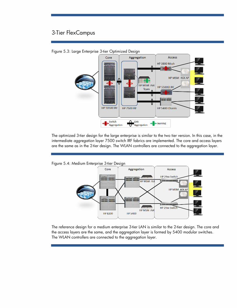
3-Tier FlexCampus
Figure 5.3: Large Enterprise 3-tier Optimized Design
The optimized 3-tier design for the large enterprise is similar to the two tier version. In this case, in the
intermediate aggregation layer 7500 switch IRF fabrics are implemented. The core and access layers
are the same as in the 2-tier design. The WLAN controllers are connected to the aggregation layer.
Figure 5.4: Medium Enterprise 3-tier Design
The reference design for a medium enterprise 3-tier LAN is similar to the 2-tier design. The core and
the access layers are the same, and the aggregation layer is formed by 5400 modular switches.
The WLAN controllers are connected to the aggregation layer.

Product Options
The following tables include different product options available for each one of the reference designs
shown above.
Table 5.1: Large Enterprise 2-tier – Product Options
Core Access WLAN Management
Main 10500 5500EI
5400
3800
3500
MSM76X
MSM46X
IMC
Alternate 7500
8200
7500
MSM76X
MSM430
IMC
Table 5.2: Medium Enterprise 2-tier – Product Options
Core Access WLAN Management
Main 8200
5400
29xx MSM76X
MSM46X
IMC
Alternate 7500 5120EI
25xx
26xx
MSM76X
MSM430
PCM+
Table 5.3: Large Enterprise – 3-tier – Product Options
Core Aggregation Access WLAN Management
Main 10500 7500
5500EI
5400
3800
3500
MSM76X
MSM46X
IMC
Alternate 8200
5400
8200
7500
MSM76X
MSM430
Table 5.4: Medium Enterprise – 3-tier – Product Options
Core Aggregation Access WLAN Management
Main 8200
5400 29xx MSM76X
MSM46X
IMC
Alternate 7500 7500 5120EI
25xx
26xx
MSM76X
MSM430
PCM+

© Copyright 2011 Hewlett-Packard Development Company, L.P. The information contained herein is subject to change without notice. The only warranties for HP products and services are set forth in the express warranty statements accompanying such products and services. Nothing herein should be construed as constituting an additional warranty. HP shall not be liable for technical or editorial errors or omissions contained herein.
Document Version 1, October 2011