Fleck SXT Timer - Pure Water Products · Fleck SXT Timer JE11 • 3. MASTER PROGRAMMING MODE CHART...
24
Fleck SXT Timer Service Manual 42713 Rev G JE11 TABLE OF CONTENTS JOB SPECIFICATION SHEET ...............................................1 INSTALLATION ......................................................................2 START-UP INSTRUCTIONS ..................................................2 TIMER FEATURES ................................................................3 TIMER OPERATION ..............................................................4 MASTER PROGRAMMING MODE CHART ..........................5 MASTER PROGRAMMING MODE ........................................6 USER PROGRAMMING MODE .............................................9 DIAGNOSTIC PROGRAMMING MODE ................................10 CONTROL VALVE ASSEMBLY ..............................................11 VALVE POWERHEAD ASSEMBLY ........................................12 3/4" TURBINE METER ASSEMBLY .......................................13 BYPASS VALVE ASSEMBLY (PLASTIC) ...............................14 BYPASS VALVE ASSEMBLY (METAL) ..................................15 2300 SAFETY BRINE VALVE.................................................16 2310 SAFETY BRINE VALVE.................................................17 TROUBLESHOOTING ...........................................................18 WATER CONDITIONER FLOW DIAGRAMS .........................20 WIRING DIAGRAM ................................................................21 SERVICE INSTRUCTIONS ....................................................22 SERVICE ASSEMBLIES ........................................................24 JOB SPECIFICATION SHEET Job Number: ___________________________________________________ Model Number: _________________________________________________ Water Hardness: _______________________________________ ppm or gpg Capacity Per Unit: _______________________________________________ Mineral Tank Size: ______________Diameter: ________ Height: _________ Salt Setting per Regeneration: _____________________________________ 1. Type of Timer: A. 7 Day or 12 Day B. Meter Initiated 2. Downflow: Upflow Upflow Variable 3. Meter Size: A. 3/4" Std Range (125 - 2,100 gallon setting) B. 3/4" Ext Range (625 - 10,625 gallon setting) C. 1" Std Range (310 - 5,270 gallon setting) D. 1" Ext Range (1,150 - 26,350 gallon setting) E. 1-1/2" Std Range (625 - 10,625 gallon setting) F. 1-1/2" Ext Range (3,125 - 53,125 gallon setting) G. 2" Std Range (1,250 - 21,250 gallon setting) H. 2" Ext Range (6,250 - 106,250 gallon setting) I. 3" Std Range (3,750 - 63,750 gallon setting) J. 3" Ext Range (18,750 - 318,750 gallon setting) K. Electronic _________ Pulse Count ________ Meter Size _______ 4. System Type: A. System #4: 1 Tank, 1 Meter, Immediate, or Delayed Regeneration B. System #4: Time Clock C. System #4: Twin Tank D. System #5: 2-5 Tanks, Interlock Mechanical 2-4 Tanks, Interlock Electronic Meter per unit for Mechanical and Electronic E. System #6: 2-5 Tanks, 1 Meter, Series Regeneration, Mechanical 2-4 Tanks, 1 Meter, Series Regeneration, Electronic F. System #7: 2-5 Tanks, 1 Meter, Alternating Regeneration, Mechanical 2 Tanks only, 1 Meter, Alternating Regeneration, Electronic G. System #9: Electronic Only, 2-4 Tanks, Meter per Valve, Alternating H. System #14: Electronic Only, 2-4 Tanks, Meter per Valve. Brings units on and offline based on flow. 5. Timer Program Settings: A. Backwash: ___________________________________ Minutes B. Brine and Slow Rinse: __________________________ Minutes C. Rapid Rinse: _________________________________ Minutes D. Brine Tank Refill: ______________________________ Minutes E. Pause Time: __________________________________ Minutes F. Second Backwash: ____________________________ Minutes 6. Drain Line Flow Control: ______________________________gpm 7. Brine Line Flow Controller: ____________________________gpm 8. Injector Size#: ____________________________________________ 9. Piston Type: A. Hard Water Bypass B. No Hard Water Bypass
Transcript of Fleck SXT Timer - Pure Water Products · Fleck SXT Timer JE11 • 3. MASTER PROGRAMMING MODE CHART...
Fleck SXT TimerService Manual
42713 Rev G JE11
TABLE OF CONTENTSJOB SPECIFICATION SHEET ...............................................1INSTALLATION ......................................................................2START-UP INSTRUCTIONS ..................................................2TIMER FEATURES ................................................................3TIMER OPERATION ..............................................................4MASTER PROGRAMMING MODE CHART ..........................5MASTER PROGRAMMING MODE ........................................6USER PROGRAMMING MODE .............................................9DIAGNOSTIC PROGRAMMING MODE ................................10CONTROL VALVE ASSEMBLY ..............................................11VALVE POWERHEAD ASSEMBLY ........................................123/4" TURBINE METER ASSEMBLY .......................................13BYPASS VALVE ASSEMBLY (PLASTIC) ...............................14BYPASS VALVE ASSEMBLY (METAL) ..................................152300 SAFETY BRINE VALVE.................................................162310 SAFETY BRINE VALVE.................................................17TROUBLESHOOTING ...........................................................18WATER CONDITIONER FLOW DIAGRAMS .........................20WIRING DIAGRAM ................................................................21SERVICE INSTRUCTIONS ....................................................22SERVICE ASSEMBLIES ........................................................24
JOB SPECIFICATION SHEETJob Number: ___________________________________________________
Model Number: _________________________________________________
Water Hardness: _______________________________________ ppm or gpg
Capacity Per Unit: _______________________________________________
Mineral Tank Size: ______________ Diameter: ________ Height: _________
Salt Setting per Regeneration: _____________________________________
1. Type of Timer:A. 7 Day or 12 Day
B. Meter Initiated
2. Downflow: Upflow UpflowVariable3. Meter Size:
A. 3/4" Std Range (125 - 2,100 gallon setting)
B. 3/4" Ext Range (625 - 10,625 gallon setting)
C. 1" Std Range (310 - 5,270 gallon setting)
D. 1" Ext Range (1,150 - 26,350 gallon setting)
E. 1-1/2" Std Range (625 - 10,625 gallon setting)
F. 1-1/2" Ext Range (3,125 - 53,125 gallon setting)
G. 2" Std Range (1,250 - 21,250 gallon setting)
H. 2" Ext Range (6,250 - 106,250 gallon setting)
I. 3" Std Range (3,750 - 63,750 gallon setting)
J. 3" Ext Range (18,750 - 318,750 gallon setting)
K. Electronic _________ Pulse Count ________ Meter Size _______
4. System Type:A. System #4: 1 Tank, 1 Meter, Immediate, or Delayed Regeneration
B. System #4: Time Clock
C. System #4: Twin Tank
D. System #5: 2-5 Tanks, Interlock Mechanical 2-4 Tanks, Interlock Electronic Meter per unit for Mechanical and Electronic
E. System #6: 2-5 Tanks, 1 Meter, Series Regeneration, Mechanical 2-4 Tanks, 1 Meter, Series Regeneration, Electronic
F. System #7: 2-5 Tanks, 1 Meter, Alternating Regeneration, Mechanical 2 Tanks only, 1 Meter, Alternating Regeneration, Electronic
G. System #9: Electronic Only, 2-4 Tanks, Meter per Valve, Alternating
H. System #14: Electronic Only, 2-4 Tanks, Meter per Valve. Brings units on and offline based on flow.
5. TimerProgramSettings:A. Backwash: ___________________________________ Minutes
B. Brine and Slow Rinse: __________________________ Minutes
C. Rapid Rinse: _________________________________ Minutes
D. Brine Tank Refill: ______________________________ Minutes
E. Pause Time: __________________________________ Minutes
F. Second Backwash: ____________________________ Minutes
6. DrainLineFlowControl: ______________________________gpm7. Brine Line Flow Controller: ____________________________gpm8. Injector Size#: ____________________________________________9. Piston Type:
A. Hard Water Bypass
B. No Hard Water Bypass

TIMERFEATURESParameter
DisplayData
DisplayPM
Indicator
Flow Indicator
x1000 Indicator
ServiceIcon
ProgrammingIcon
Extra CycleButton
UpButton
DownButton
Error/InformationIcon
Figure 1
FeaturesoftheSXT:• Power backup that continues to keep time and the
passage of days for a minimum of 48 hours in the event of power failure. During a power outage, the control goes into a power-saving mode. It does not monitor water usage during a power failure, but it does store the volume remaining at the time of power failure.
• Settings for both valve (basic system) and control type (method used to trigger a regeneration).
• Day-of-the-Week controls.• While in service, the display alternates between time of
day, volume remaining or days to regeneration, and tank in service (twin tank systems only).
• The Flow Indicator flashes when outlet flow is detected.• The Service Icon flashes if a regeneration cycle has been
queued.• A Regeneration can be triggered immediately by pressing
the Extra Cycle button for five seconds.• The Parameter Display displays the current Cycle Step
(BW, BF, RR, etc) during regeneration, and the data display counts down the time remaining for that cycle step. While the valve is transferring to a new cycle step, the display will flash. The parameter display will identify the destination cycle step (BW, BF, RR, etc) and the data display will read “----”. Once the valve reaches the cycle step, the display will stop flashing and the data display will change to the time remaining. During regeneration, the user can force the control to advance to the next cycle step immediately by pressing the extra cycle button.
SettingtheTimeofDay1. Press and hold either the Up or Down buttons until the
programming icon replaces the service icon and the parameter display reads DO.
2. Adjust the displayed time with the Up and Down buttons.3. When the desired time is set, press the Extra Cycle button
to resume normal operation. The unit will also return to normal operation after 5 seconds if no buttons are pressed.
QueueingaRegeneration1. Press the Extra Cycle button. The service icon will flash to
indicate that a regeneration is queued.2. To cancel a queued regeneration, press the Extra Cycle
button.
RegeneratingImmediatelyPress and hold the Extra Cycle button for five seconds.
42637 Rev D
2 • JE11 Fleck SXT Timer
TIMER OPERATIONMeterImmediateControlA meter immediate control measures water usage and regenerates the system as soon as the calculated system capacity is depleted. The control calculates the system capacity by dividing the unit capacity (typically expressed in grains/unit volume) by the feedwater hardness and subtracting the reserve. Meter Immediate systems generally do not use a reserve volume. However, in twin tank systems with soft-water regeneration, the reserve capacity should be set to the volume of water used during regeneration to prevent hard water break-through. A Meter Immediate control will also start a regeneration cycle at the programmed regeneration time if a number of days equal to the regeneration day override pass before water usage depletes the calculated system capacity.
MeterDelayedControlA Meter Delayed Control measures water usage and regenerates the system at the programmed regeneration time after the calculated system capacity is depleted. As with Meter Immediate systems, the control calculates the system capacity by dividing the unit capacity by the feedwater hardness and subtracting the reserve. The reserve should be set to insure that the system delivers treated water between the time the system capacity is depleted and the actual regeneration time. A Meter Delayed control will also start a regeneration cycle at the programmed regeneration time if a number of days equal to the regeneration day override pass before water usage depletes the calculated system capacity.
TimeClockDelayedControlA Time Clock Delayed Control regenerates the system on a timed interval. The control will initiate a regeneration cycle at the programmed regeneration time when the number of days since the last regeneration equals the regeneration day override value.
DayoftheWeekControlThis control regenerates the system on a weekly schedule. The schedule is defined in Master Programming by setting each day to either “off” or “on.” The control will initiates a regeneration cycle on days that have been set to “on” at the specified regeneration time.
ControlOperationDuringRegenerationDuring regeneration, the control displays a special regeneration display. In this display, the control shows the current regeneration step number the valve is advancing to, or has reached, and the time remaining in that step. The step number that displays flashes until the valve completes driving to this regeneration step position. Once all regeneration steps are complete the valve returns to service and resumes normal operation.Pressing the Extra Cycle button during a regeneration cycle immediately advances the valve to the next cycle step position and resumes normal step timing.
ControlOperationDuringProgrammingThe control only enters the Program Mode with the valve in service. While in the Program Mode, the control continues to operate normally monitoring water usage and keeping all displays up to date. Control programming is stored in memory permanently, eliminating the need for battery backup power.
ManuallyInitiatingaRegeneration1. When timer is in service, press the Extra Cycle button for 5
seconds on the main screen.2. The timer advances to Regeneration Cycle Step #1 (rapid
rinse), and begins programmed time count down.3. Press the Extra Cycle button once to advance valve to
Regeneration Cycle Step #2 (backwash).4. Press the Extra Cycle button once to advance valve to
Regeneration Cycle Step #3 (brine draw & slow rinse).5. Press the Extra Cycle button once to advance valve to
Regeneration Cycle Step #4 (brine refill).6. Press the Extra Cycle button once more to advance the
valve back to in service.NOTE:Iftheunitisafilterorupflow,thecyclestep
ordermaychange.NOTE:Aqueuedregenerationcanbeinitiatedby
pressingtheExtraCyclebutton.Toclearaqueuedregeneration,presstheExtraCyclebuttonagaintocancel.Ifregenerationoccursforanyreasonpriortothedelayedregenerationtime,themanualregenerationrequestshallbecleared.
ControlOperationDuringAPowerFailureThe SXT includes integral power backup. In the event of power failure, the control shifts into a power-saving mode. The control stops monitoring water usage, and the display and motor shut down, but it continues to keep track of the time and day for a minimum of 48 hours.The system configuration settings are stored in a non-volatile memory and are stored indefinitely with or without line power. The Time of Day flashes when there has been a power failure. Press any button to stop the Time of Day from flashing.If power fails while the unit is in regeneration, the control will save the current valve position before it shuts down. When power is restored, the control will resume the regeneration cycle from the point where power failed. Note that if power fails during a regeneration cycle, the valve will remain in it’s current position until power is restored. The valve system should include all required safety components to prevent overflows resulting from a power failure during regeneration. The control will not start a new regeneration cycle without line power. If the valve misses a scheduled regeneration due to a power failure, it will queue a regeneration. Once power is restored, the control will initiate a regeneration cycle the next time that the Time of Day equals the programmed regeneration time. Typically, this means that the valve will regenerate one day after it was originally scheduled. If the treated water output is important and power interruptions are expected, the system should be setup with a sufficient reserve capacity to compensate for regeneration delays.
Fleck SXT Timer JE11 • 3
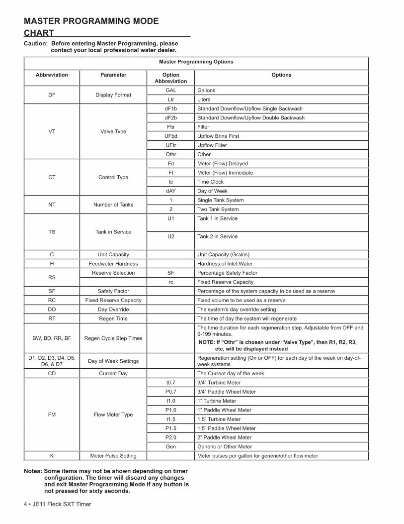
MASTER PROGRAMMING MODE CHARTCaution:BeforeenteringMasterProgramming,please
contactyourlocalprofessionalwaterdealer.
MasterProgrammingOptions
Abbreviation Parameter Option Abbreviation
Options
DF Display FormatGAL Gallons
Ltr Liters
VT Valve Type
dF1b Standard Downflow/Upflow Single Backwash
dF2b Standard Downflow/Upflow Double Backwash
Fltr Filter
UFbd Upflow Brine First
UFtr Upflow Filter
Othr Other
CT Control Type
Fd Meter (Flow) Delayed
FI Meter (Flow) Immediate
tc Time Clock
dAY Day of Week
NT Number of Tanks1 Single Tank System
2 Two Tank System
TS Tank in Service
U1 Tank 1 in Service
U2 Tank 2 in Service
C Unit Capacity Unit Capacity (Grains)
H Feedwater Hardness Hardness of Inlet Water
RSReserve Selection SF Percentage Safety Factor
rc Fixed Reserve Capacity
SF Safety Factor Percentage of the system capacity to be used as a reserve
RC Fixed Reserve Capacity Fixed volume to be used as a reserve
DO Day Override The system’s day override setting
RT Regen Time The time of day the system will regenerate
BW, BD, RR, BF Regen Cycle Step Times
The time duration for each regeneration step. Adjustable from OFF and 0-199 minutes.NOTE:If“Othr”ischosenunder“ValveType”,thenR1,R2,R3,
etc,willbedisplayedinsteadD1, D2, D3, D4, D5,
D6, & D7 Day of Week Settings Regeneration setting (On or OFF) for each day of the week on day-of-week systems
CD Current Day The Current day of the week
FM Flow Meter Type
t0.7 3/4” Turbine Meter
P0.7 3/4” Paddle Wheel Meter
t1.0 1” Turbine Meter
P1.0 1” Paddle Wheel Meter
t1.5 1.5” Turbine Meter
P1.5 1.5” Paddle Wheel Meter
P2.0 2” Paddle Wheel Meter
Gen Generic or Other Meter
K Meter Pulse Setting Meter pulses per gallon for generic/other flow meter
Notes:Someitemsmaynotbeshowndependingontimerconfiguration.ThetimerwilldiscardanychangesandexitMasterProgrammingModeifanybuttonisnotpressedforsixtyseconds.
4 • JE11 Fleck SXT Timer
MASTER PROGRAMMING MODEWhen the Master Programming Mode is entered, all available option setting displays may be viewed and set as needed. Depending on current option settings, some parameters cannot be viewed or set.
SettingtheTimeofDay1. Press and hold either the Up or Down buttons until the
programming icon replaces the service icon and the parameter display reads DO.
2. Adjust the displayed time with the Up and Down buttons.3. When the desired time is set, press the Extra Cycle button
to resume normal operation. The unit will also return to normal operation after 5 seconds if no buttons are pressed.
EnteringMasterProgrammingModeSet the Time Of Day display to 12:01 P.M. Press the Extra Cycle button (to exit Setting Time of Day mode). Then press and hold the Up and Down buttons together until the programming icon replaces the service icon and the Display Format screen appears.
ExitingMasterProgrammingModePress the Extra Cycle button to accept the displayed settings and cycle to the next parameter. Press the Extra Cycle button at the last parameter to save all settings and return to normal operation. The control will automatically disregard any programming changes and return to normal operation if it is left in Master Programming mode for 5 minutes without any keypad input.
Resets
Soft Reset: Press and hold the Extra Cycle and Down buttons for 25 seconds while in normal Service mode. This resets all parameters to the system default values, except the volume remaining in meter immediate or meter delayed systems and days since regeneration in the time clock system.
MasterReset:Hold the Extra Cycle button while powering up the unit. This resets all of the parameters in the unit. Check and verify the choices selected in Master Programming Mode.
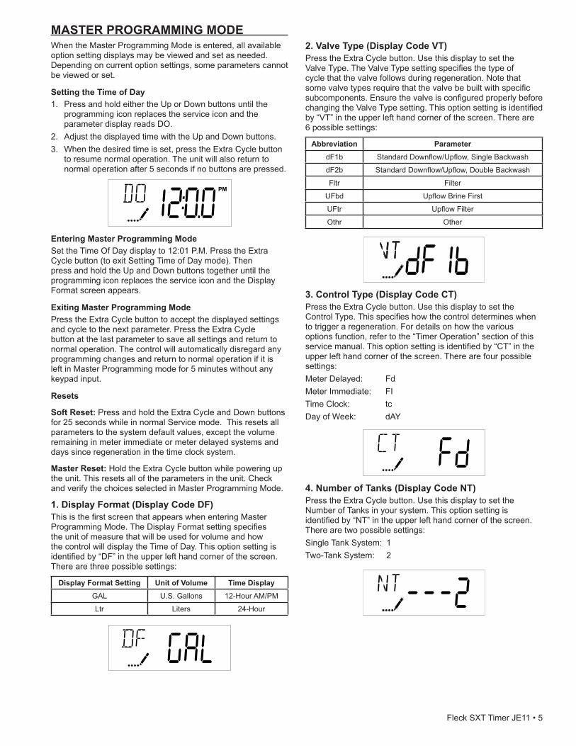
1.DisplayFormat(DisplayCodeDF)This is the first screen that appears when entering Master Programming Mode. The Display Format setting specifies the unit of measure that will be used for volume and how the control will display the Time of Day. This option setting is identified by “DF” in the upper left hand corner of the screen. There are three possible settings:
DisplayFormatSetting UnitofVolume TimeDisplayGAL U.S. Gallons 12-Hour AM/PM
Ltr Liters 24-Hour
2.ValveType(DisplayCodeVT)Press the Extra Cycle button. Use this display to set the Valve Type. The Valve Type setting specifies the type of cycle that the valve follows during regeneration. Note that some valve types require that the valve be built with specific subcomponents. Ensure the valve is configured properly before changing the Valve Type setting. This option setting is identified by “VT” in the upper left hand corner of the screen. There are 6 possible settings:
Abbreviation ParameterdF1b Standard Downflow/Upflow, Single Backwash
dF2b Standard Downflow/Upflow, Double Backwash
Fltr Filter
UFbd Upflow Brine First
UFtr Upflow Filter
Othr Other
3.ControlType(DisplayCodeCT)Press the Extra Cycle button. Use this display to set the Control Type. This specifies how the control determines when to trigger a regeneration. For details on how the various options function, refer to the “Timer Operation” section of this service manual. This option setting is identified by “CT” in the upper left hand corner of the screen. There are four possible settings:Meter Delayed: FdMeter Immediate: FITime Clock: tcDay of Week: dAY
4.NumberofTanks(DisplayCodeNT)Press the Extra Cycle button. Use this display to set the Number of Tanks in your system. This option setting is identified by “NT” in the upper left hand corner of the screen. There are two possible settings:Single Tank System: 1Two-Tank System: 2
Fleck SXT Timer JE11 • 5
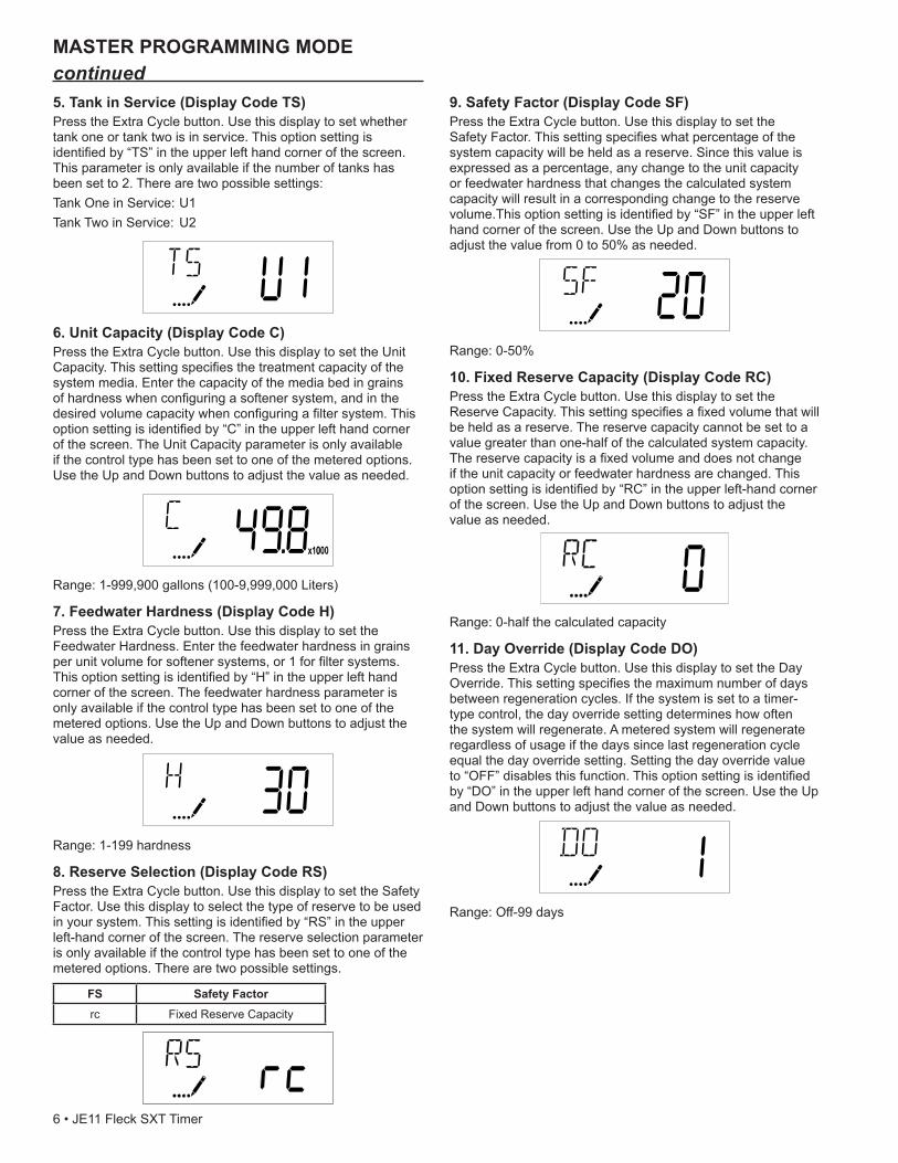
5.TankinService(DisplayCodeTS)Press the Extra Cycle button. Use this display to set whether tank one or tank two is in service. This option setting is identified by “TS” in the upper left hand corner of the screen. This parameter is only available if the number of tanks has been set to 2. There are two possible settings:Tank One in Service: U1Tank Two in Service: U2
6.UnitCapacity(DisplayCodeC)Press the Extra Cycle button. Use this display to set the Unit Capacity. This setting specifies the treatment capacity of the system media. Enter the capacity of the media bed in grains of hardness when configuring a softener system, and in the desired volume capacity when configuring a filter system. This option setting is identified by “C” in the upper left hand corner of the screen. The Unit Capacity parameter is only available if the control type has been set to one of the metered options. Use the Up and Down buttons to adjust the value as needed.
Range: 1-999,900 gallons (100-9,999,000 Liters)
7.FeedwaterHardness(DisplayCodeH)Press the Extra Cycle button. Use this display to set the Feedwater Hardness. Enter the feedwater hardness in grains per unit volume for softener systems, or 1 for filter systems. This option setting is identified by “H” in the upper left hand corner of the screen. The feedwater hardness parameter is only available if the control type has been set to one of the metered options. Use the Up and Down buttons to adjust the value as needed.
Range: 1-199 hardness
8.ReserveSelection(DisplayCodeRS)Press the Extra Cycle button. Use this display to set the Safety Factor. Use this display to select the type of reserve to be used in your system. This setting is identified by “RS” in the upper left-hand corner of the screen. The reserve selection parameter is only available if the control type has been set to one of the metered options. There are two possible settings.
FS SafetyFactorrc Fixed Reserve Capacity
9.SafetyFactor(DisplayCodeSF)Press the Extra Cycle button. Use this display to set the Safety Factor. This setting specifies what percentage of the system capacity will be held as a reserve. Since this value is expressed as a percentage, any change to the unit capacity or feedwater hardness that changes the calculated system capacity will result in a corresponding change to the reserve volume.This option setting is identified by “SF” in the upper left hand corner of the screen. Use the Up and Down buttons to adjust the value from 0 to 50% as needed.
Range: 0-50%
10.FixedReserveCapacity(DisplayCodeRC)Press the Extra Cycle button. Use this display to set the Reserve Capacity. This setting specifies a fixed volume that will be held as a reserve. The reserve capacity cannot be set to a value greater than one-half of the calculated system capacity. The reserve capacity is a fixed volume and does not change if the unit capacity or feedwater hardness are changed. This option setting is identified by “RC” in the upper left-hand corner of the screen. Use the Up and Down buttons to adjust the value as needed.
Range: 0-half the calculated capacity
11.DayOverride(DisplayCodeDO)Press the Extra Cycle button. Use this display to set the Day Override. This setting specifies the maximum number of days between regeneration cycles. If the system is set to a timer-type control, the day override setting determines how often the system will regenerate. A metered system will regenerate regardless of usage if the days since last regeneration cycle equal the day override setting. Setting the day override value to “OFF” disables this function. This option setting is identified by “DO” in the upper left hand corner of the screen. Use the Up and Down buttons to adjust the value as needed.
Range: Off-99 days
MASTER PROGRAMMING MODE continued
6 • JE11 Fleck SXT Timer
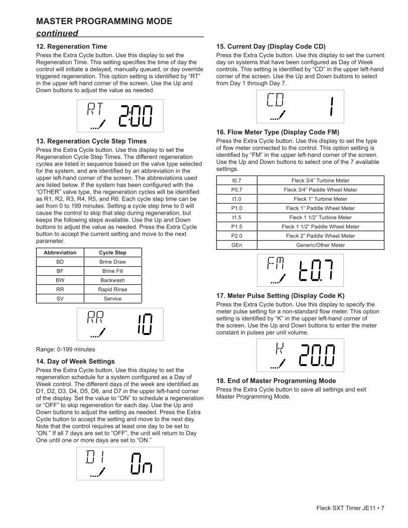
12.RegenerationTimePress the Extra Cycle button. Use this display to set the Regeneration Time. This setting specifies the time of day the control will initiate a delayed, manually queued, or day override triggered regeneration. This option setting is identified by “RT” in the upper left hand corner of the screen. Use the Up and Down buttons to adjust the value as needed.
13.RegenerationCycleStepTimesPress the Extra Cycle button. Use this display to set the Regeneration Cycle Step Times. The different regeneration cycles are listed in sequence based on the valve type selected for the system, and are identified by an abbreviation in the upper left-hand corner of the screen. The abbreviations used are listed below. If the system has been configured with the “OTHER” valve type, the regeneration cycles will be identified as R1, R2, R3, R4, R5, and R6. Each cycle step time can be set from 0 to 199 minutes. Setting a cycle step time to 0 will cause the control to skip that step during regeneration, but keeps the following steps available. Use the Up and Down buttons to adjust the value as needed. Press the Extra Cycle button to accept the current setting and move to the next parameter.
Abbreviation Cycle StepBD Brine Draw
BF Brine Fill
BW Backwash
RR Rapid Rinse
SV Service
Range: 0-199 minutes
14.DayofWeekSettingsPress the Extra Cycle button. Use this display to set the regeneration schedule for a system configured as a Day of Week control. The different days of the week are identified as D1, D2, D3, D4, D5, D6, and D7 in the upper left-hand corner of the display. Set the value to “ON” to schedule a regeneration or “OFF” to skip regeneration for each day. Use the Up and Down buttons to adjust the setting as needed. Press the Extra Cycle button to accept the setting and move to the next day. Note that the control requires at least one day to be set to “ON.” If all 7 days are set to “OFF”, the unit will return to Day One until one or more days are set to “ON.”
MASTER PROGRAMMING MODE continued
15.CurrentDay(DisplayCodeCD)Press the Extra Cycle button. Use this display to set the current day on systems that have been configured as Day of Week controls. This setting is identified by “CD” in the upper left-hand corner of the screen. Use the Up and Down buttons to select from Day 1 through Day 7.
16.FlowMeterType(DisplayCodeFM)Press the Extra Cycle button. Use this display to set the type of flow meter connected to the control. This option setting is identified by “FM” in the upper left-hand corner of the screen. Use the Up and Down buttons to select one of the 7 available settings.
t0.7 Fleck 3/4” Turbine Meter
P0.7 Fleck 3/4” Paddle Wheel Meter
t1.0 Fleck 1” Turbine Meter
P1.0 Fleck 1” Paddle Wheel Meter
t1.5 Fleck 1 1/2” Turbine Meter
P1.5 Fleck 1 1/2” Paddle Wheel Meter
P2.0 Fleck 2” Paddle Wheel Meter
GEn Generic/Other Meter
17.MeterPulseSetting(DisplayCodeK)Press the Extra Cycle button. Use this display to specify the meter pulse setting for a non-standard flow meter. This option setting is identified by “K” in the upper left-hand corner of the screen. Use the Up and Down buttons to enter the meter constant in pulses per unit volume.
18.EndofMasterProgrammingModePress the Extra Cycle button to save all settings and exit Master Programming Mode.
Fleck SXT Timer JE11 • 7
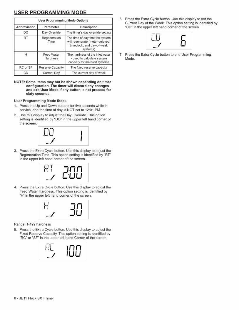
USERPROGRAMMINGMODEUserProgrammingModeOptions
Abbreviation Parameter DescriptionDO Day Override The timer’s day override setting
RT Regeneration Time
The time of day that the system will regenerate (meter delayed,
timeclock, and day-of-week systems)
H Feed Water Hardness
The hardness of the inlet water - used to calculate system
capacity for metered systems
RC or SF Reserve Capacity The fixed reserve capacity
CD Current Day The current day of week
NOTE:Someitemsmaynotbeshowndependingontimerconfiguration.ThetimerwilldiscardanychangesandexitUserModeifanybuttonisnotpressedforsixtyseconds.
UserProgrammingModeSteps1. Press the Up and Down buttons for five seconds while in
service, and the time of day is NOT set to 12:01 PM.2. Use this display to adjust the Day Override. This option
setting is identified by “DO” in the upper left hand corner of the screen.
3. Press the Extra Cycle button. Use this display to adjust the Regeneration Time. This option setting is identified by “RT” in the upper left hand corner of the screen.
4. Press the Extra Cycle button. Use this display to adjust the Feed Water Hardness. This option setting is identified by “H” in the upper left hand corner of the screen.
Range: 1-199 hardness5. Press the Extra Cycle button. Use this display to adjust the
Fixed Reserve Capacity. This option setting is identified by “RC” or "SF" in the upper left-hand Corner of the screen.
6. Press the Extra Cycle button. Use this display to set the Current Day of the Week. This option setting is identified by “CD” in the upper left hand corner of the screen.
7. Press the Extra Cycle button to end User Programming Mode.
8 • JE11 Fleck SXT Timer
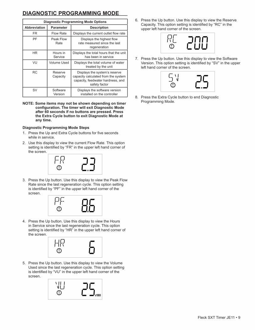
DIAGNOSTIC PROGRAMMING MODEDiagnosticProgrammingModeOptions
Abbreviation Parameter DescriptionFR Flow Rate Displays the current outlet flow rate
PF Peak Flow Rate
Displays the highest flow rate measured since the last
regeneration
HR Hours in Service
Displays the total hours that the unit has been in service
VU Volume Used Displays the total volume of water treated by the unit
RC Reserve Capacity
Displays the system’s reserve capacity calculated from the system capacity, feedwater hardness, and
safety factor
SV Software Version
Displays the software version installed on the controller
NOTE:Someitemsmaynotbeshowndependingontimer
configuration.ThetimerwillexitDiagnosticModeafter60secondsifnobuttonsarepressed.PresstheExtraCyclebuttontoexitDiagnosticModeatanytime.
DiagnosticProgrammingModeSteps1. Press the Up and Extra Cycle buttons for five seconds
while in service.2. Use this display to view the current Flow Rate. This option
setting is identified by “FR” in the upper left hand corner of the screen.
3. Press the Up button. Use this display to view the Peak Flow Rate since the last regeneration cycle. This option setting is identified by “PF” in the upper left hand corner of the screen.
4. Press the Up button. Use this display to view the Hours in Service since the last regeneration cycle. This option setting is identified by “HR” in the upper left hand corner of the screen.
5. Press the Up button. Use this display to view the Volume Used since the last regeneration cycle. This option setting is identified by “VU” in the upper left hand corner of the screen.
6. Press the Up button. Use this display to view the Reserve Capacity. This option setting is identified by “RC” in the upper left hand corner of the screen.
7. Press the Up button. Use this display to view the Software Version. This option setting is identified by “SV” in the upper left hand corner of the screen.
8. Press the Extra Cycle button to end Diagnostic Programming Mode.
Fleck SXT Timer JE11 • 9
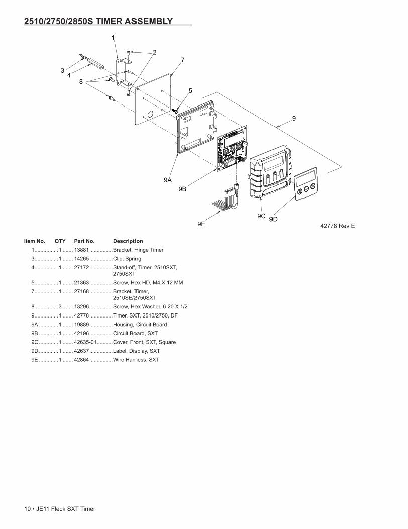
ItemNo. QTY PartNo. Description 1 ................1 ....... 13881 ................Bracket, Hinge Timer 3 ................1 ....... 14265 ................Clip, Spring 4 ................1 ....... 27172 ................Stand-off, Timer, 2510SXT,
2750SXT 5 ................1 ....... 21363 ................Screw, Hex HD, M4 X 12 MM 7 ................1 ....... 27168 ................Bracket, Timer,
2510SE/2750SXT 8 ................3 ....... 13296 ................Screw, Hex Washer, 6-20 X 1/2 9 ................1 ....... 42778 ................Timer, SXT, 2510/2750, DF 9A .............1 ....... 19889 ................Housing, Circuit Board 9B .............1 ....... 42196 ................Circuit Board, SXT 9C .............1 ....... 42635-01 ...........Cover, Front, SXT, Square 9D .............1 ....... 42637 ................Label, Display, SXT 9E .............1 ....... 42864 ................Wire Harness, SXT
2510/2750/2850S TIMER ASSEMBLY
42778 Rev E
9
3 4
1
2 7
5
9A 9B
9C 9D
8
9E
10 • JE11 Fleck SXT Timer
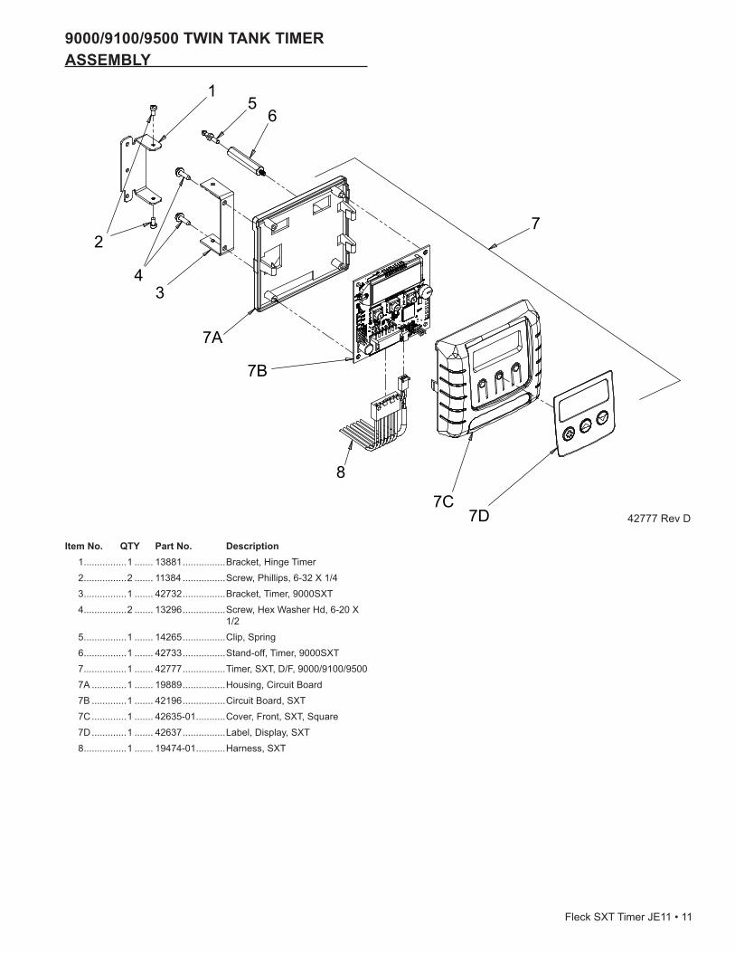
9000/9100/9500TWINTANKTIMERASSEMBLY
ItemNo. QTY PartNo. Description 1 ................1 ....... 13881 ................Bracket, Hinge Timer 2 ................2 ....... 11384 ................Screw, Phillips, 6-32 X 1/4 3 ................1 ....... 42732 ................Bracket, Timer, 9000SXT 4 ................2 ....... 13296 ................Screw, Hex Washer Hd, 6-20 X
1/2 5 ................1 ....... 14265 ................Clip, Spring 6 ................1 ....... 42733 ................Stand-off, Timer, 9000SXT 7 ................1 ....... 42777 ................Timer, SXT, D/F, 9000/9100/9500 7A .............1 ....... 19889 ................Housing, Circuit Board 7B .............1 ....... 42196 ................Circuit Board, SXT 7C .............1 ....... 42635-01 ...........Cover, Front, SXT, Square 7D .............1 ....... 42637 ................Label, Display, SXT 8 ................1 ....... 19474-01 ...........Harness, SXT
42777 Rev D
1
2
4 3
5 6
7A
7B
7C 7D
7
8
Fleck SXT Timer JE11 • 11
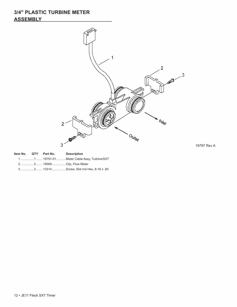
3/4"PLASTICTURBINEMETERASSEMBLY
19797 Rev A
ItemNo. QTY PartNo. Description 1 ................1 ....... 19791-01 ...........Meter Cable Assy, Turbine/SXT 2 ................2 ....... 19569 ................Clip, Flow Meter 3 ................2 ....... 13314 ................Screw, Slot Ind Hex, 8-18 x .60
12 • JE11 Fleck SXT Timer
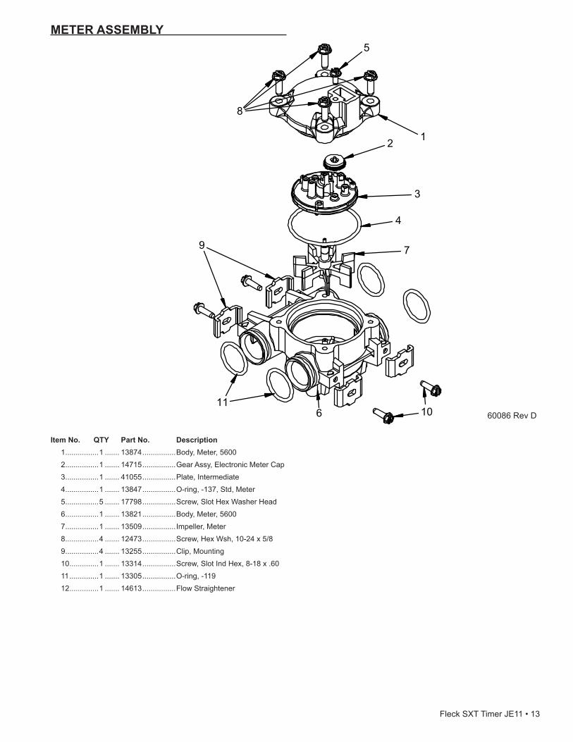
METER ASSEMBLY
ItemNo. QTY PartNo. Description 1 ................1 ....... 13874 ................Body, Meter, 5600 2 ................1 ....... 14715 ................Gear Assy, Electronic Meter Cap 3 ................1 ....... 41055 ................Plate, Intermediate 4 ................1 ....... 13847 ................O-ring, -137, Std, Meter 5 ................5 ....... 17798 ................Screw, Slot Hex Washer Head 6 ................1 ....... 13821 ................Body, Meter, 5600 7 ................1 ....... 13509 ................Impeller, Meter 8 ................4 ....... 12473 ................Screw, Hex Wsh, 10-24 x 5/8 9 ................4 ....... 13255 ................Clip, Mounting 10 ..............1 ....... 13314 ................Screw, Slot Ind Hex, 8-18 x .60 11 ..............1 ....... 13305 ................O-ring, -119 12 ..............1 ....... 14613 ................Flow Straightener
60086 Rev D
Fleck SXT Timer JE11 • 13
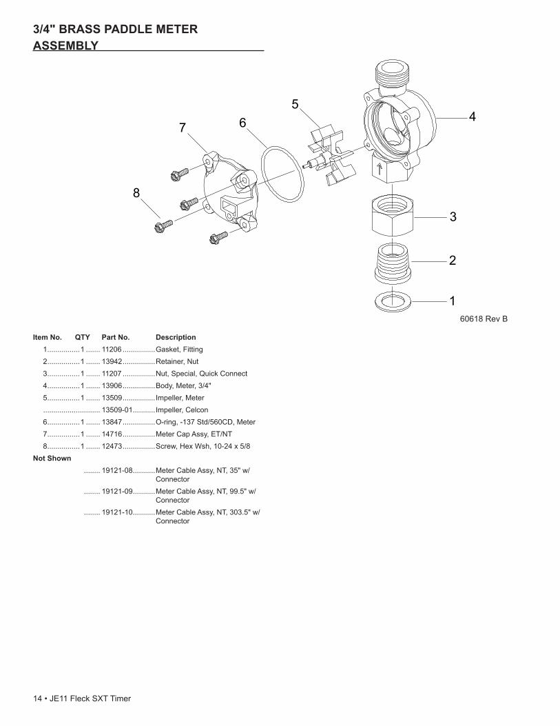
3/4" BRASS PADDLE METER ASSEMBLY
ItemNo. QTY PartNo. Description 1 ................1 ....... 11206 ................Gasket, Fitting 2 ................1 ....... 13942 ................Retainer, Nut 3 ................1 ....... 11207 ................Nut, Special, Quick Connect 4 ................1 ....... 13906 ................Body, Meter, 3/4" 5 ................1 ....... 13509 ................Impeller, Meter ............................ 13509-01 ...........Impeller, Celcon 6 ................1 ....... 13847 ................O-ring, -137 Std/560CD, Meter 7 ................1 ....... 14716 ................Meter Cap Assy, ET/NT 8 ................1 ....... 12473 ................Screw, Hex Wsh, 10-24 x 5/8NotShown ........ 19121-08 ...........Meter Cable Assy, NT, 35" w/
Connector ........ 19121-09 ...........Meter Cable Assy, NT, 99.5" w/
Connector ........ 19121-10 ...........Meter Cable Assy, NT, 303.5" w/
Connector
60618 Rev B
14 • JE11 Fleck SXT Timer
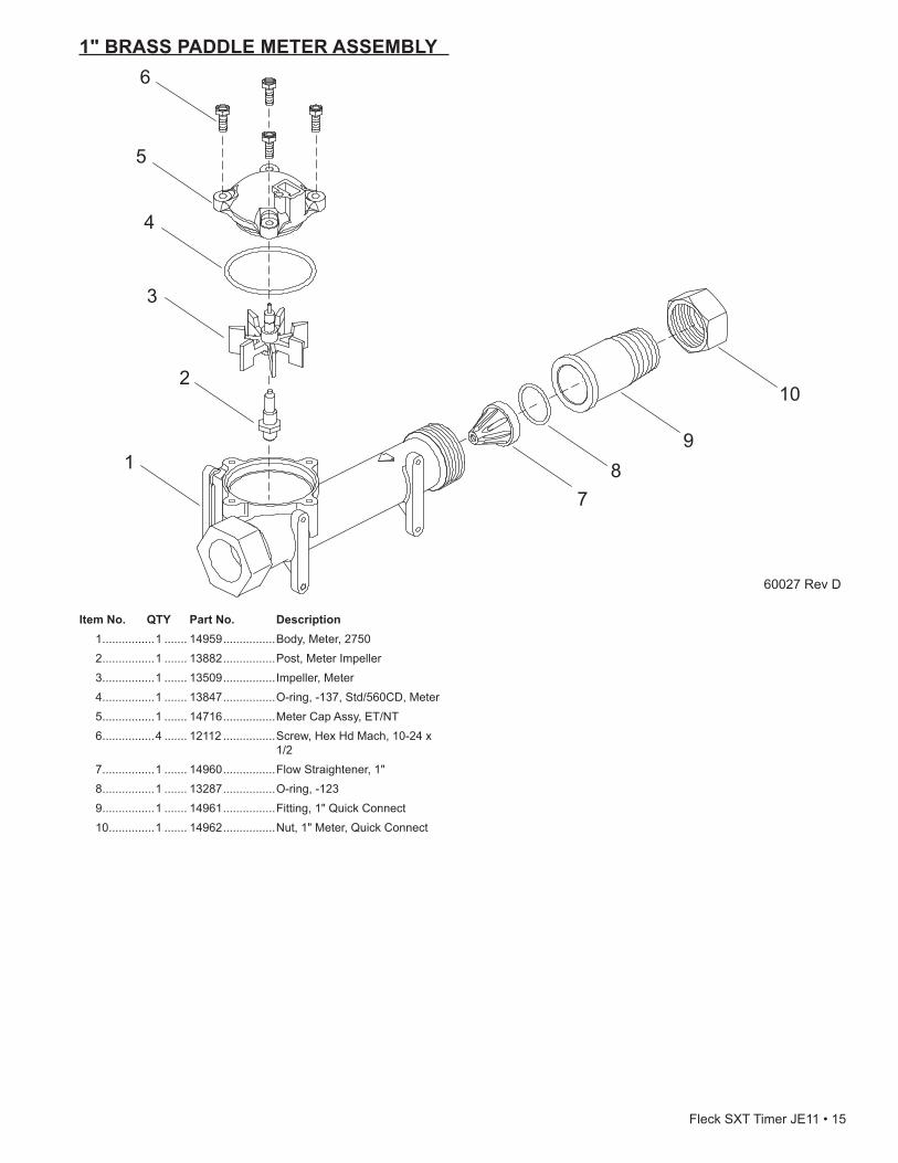
1" BRASS PADDLE METER ASSEMBLY
ItemNo. QTY PartNo. Description 1 ................1 ....... 14959 ................Body, Meter, 2750 2 ................1 ....... 13882 ................Post, Meter Impeller 3 ................1 ....... 13509 ................Impeller, Meter 4 ................1 ....... 13847 ................O-ring, -137, Std/560CD, Meter 5 ................1 ....... 14716 ................Meter Cap Assy, ET/NT 6 ................4 ....... 12112 ................Screw, Hex Hd Mach, 10-24 x
1/2 7 ................1 ....... 14960 ................Flow Straightener, 1" 8 ................1 ....... 13287 ................O-ring, -123 9 ................1 ....... 14961 ................Fitting, 1" Quick Connect 10 ..............1 ....... 14962 ................Nut, 1" Meter, Quick Connect
60027 Rev D
Fleck SXT Timer JE11 • 15
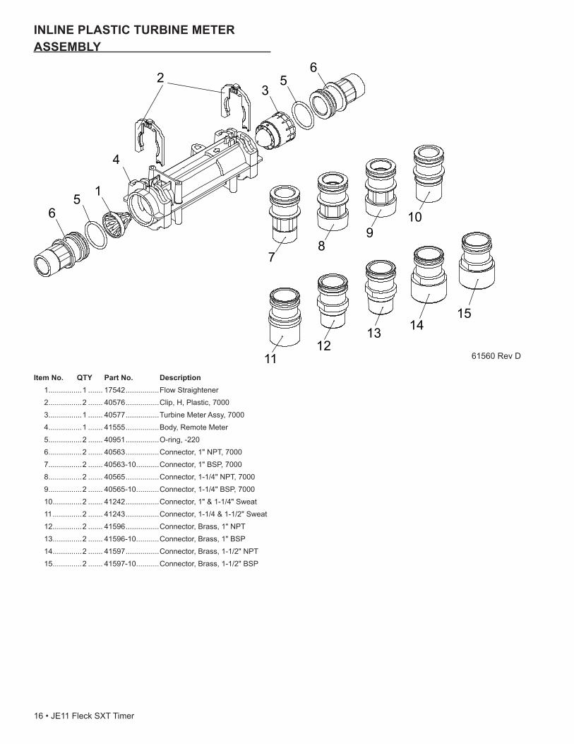
INLINEPLASTICTURBINEMETERASSEMBLY
ItemNo. QTY PartNo. Description 1 ................1 ....... 17542 ................Flow Straightener 2 ................2 ....... 40576 ................Clip, H, Plastic, 7000 3 ................1 ....... 40577 ................Turbine Meter Assy, 7000 4 ................1 ....... 41555 ................Body, Remote Meter 5 ................2 ....... 40951 ................O-ring, -220 6 ................2 ....... 40563 ................Connector, 1" NPT, 7000 7 ................2 ....... 40563-10 ...........Connector, 1" BSP, 7000 8 ................2 ....... 40565 ................Connector, 1-1/4" NPT, 7000 9 ................2 ....... 40565-10 ...........Connector, 1-1/4" BSP, 7000 10 ..............2 ....... 41242 ................Connector, 1" & 1-1/4" Sweat 11 ..............2 ....... 41243 ................Connector, 1-1/4 & 1-1/2" Sweat 12 ..............2 ....... 41596 ................Connector, Brass, 1" NPT 13 ..............2 ....... 41596-10 ...........Connector, Brass, 1" BSP 14 ..............2 ....... 41597 ................Connector, Brass, 1-1/2" NPT 15 ..............2 ....... 41597-10 ...........Connector, Brass, 1-1/2" BSP
61560 Rev D
16 • JE11 Fleck SXT Timer
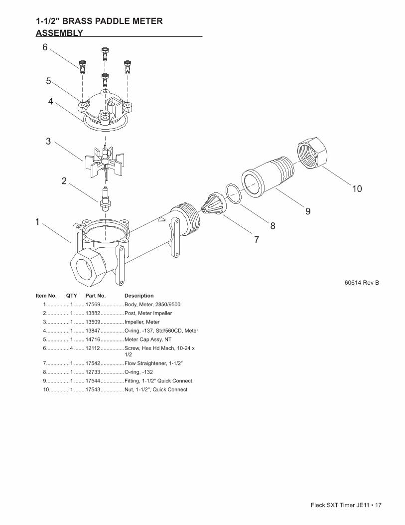
1-1/2" BRASS PADDLE METER ASSEMBLY
ItemNo. QTY PartNo. Description 1 ................1 ....... 17569 ................Body, Meter, 2850/9500 2 ................1 ....... 13882 ................Post, Meter Impeller 3 ................1 ....... 13509 ................Impeller, Meter 4 ................1 ....... 13847 ................O-ring, -137, Std/560CD, Meter 5 ................1 ....... 14716 ................Meter Cap Assy, NT 6 ................4 ....... 12112 ................Screw, Hex Hd Mach, 10-24 x
1/2 7 ................1 ....... 17542 ................Flow Straightener, 1-1/2" 8 ................1 ....... 12733 ................O-ring, -132 9 ................1 ....... 17544 ................Fitting, 1-1/2" Quick Connect 10 ..............1 ....... 17543 ................Nut, 1-1/2", Quick Connect
60614 Rev B
Fleck SXT Timer JE11 • 17

3/4",1"or1-1/2"PADDLEWHEELMETER CAP ASSEMBLY
ItemNo. QTY PartNo. Description 1 ................1 ....... 14716 ................Meter Cap Assy, NT 2 ................1 ....... 19121-01 ...........Meter Cable Assy, SXT, Paddle
6700XTR 3 ................1 ....... 13847 ................O-ring, -137, Std/560CD, Meter 4 ................1 ....... 17798 ................Screw, Slot Hex Wsh Hd
18 • JE11 Fleck SXT Timer
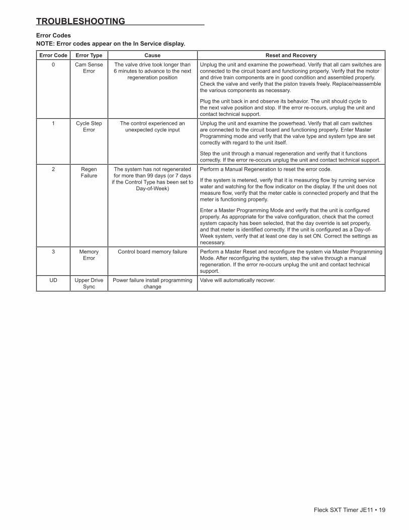
TROUBLESHOOTINGErrorCodesNOTE:ErrorcodesappearontheInServicedisplay.
ErrorCode Error Type Cause ResetandRecovery0 Cam Sense
ErrorThe valve drive took longer than 6 minutes to advance to the next
regeneration position
Unplug the unit and examine the powerhead. Verify that all cam switches are connected to the circuit board and functioning properly. Verify that the motor and drive train components are in good condition and assembled properly. Check the valve and verify that the piston travels freely. Replace/reassemble the various components as necessary.
Plug the unit back in and observe its behavior. The unit should cycle to the next valve position and stop. If the error re-occurs, unplug the unit and contact technical support.
1 Cycle Step Error
The control experienced an unexpected cycle input
Unplug the unit and examine the powerhead. Verify that all cam switches are connected to the circuit board and functioning properly. Enter Master Programming mode and verify that the valve type and system type are set correctly with regard to the unit itself.
Step the unit through a manual regeneration and verify that it functions correctly. If the error re-occurs unplug the unit and contact technical support.
2 Regen Failure
The system has not regenerated for more than 99 days (or 7 days
if the Control Type has been set to Day-of-Week)
Perform a Manual Regeneration to reset the error code.
If the system is metered, verify that it is measuring flow by running service water and watching for the flow indicator on the display. If the unit does not measure flow, verify that the meter cable is connected properly and that the meter is functioning properly.
Enter a Master Programming Mode and verify that the unit is configured properly. As appropriate for the valve configuration, check that the correct system capacity has been selected, that the day override is set properly, and that meter is identified correctly. If the unit is configured as a Day-of-Week system, verify that at least one day is set ON. Correct the settings as necessary.
3 Memory Error
Control board memory failure Perform a Master Reset and reconfigure the system via Master Programming Mode. After reconfiguring the system, step the valve through a manual regeneration. If the error re-occurs unplug the unit and contact technical support.
UD Upper Drive Sync
Power failure install programming change
Valve will automatically recover.
Fleck SXT Timer JE11 • 19
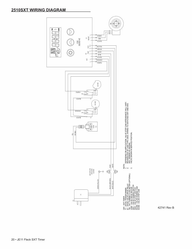
2510SXTWIRINGDIAGRAM
SCA
M
HC
AM
C
N.O.
N.C.SW2
C
N.O.
N.C.SW1
VD
M
T1
H-
-S
WHITENN
GREEN
TM
PURPLE
ORANGE
WH
ITE
YEL
S
PWR
VD
OM
ETER +
BLUE
WT/
BLK
BLUE
BLACK
HN
.O.
P2
RED
BLACK
P1
BLACK
ORANGE
BLACK
PURPLE
WT/BLK
YELLOW
WH
ITE (B
LUE)
H/S
BLA
CK
(BRO
WN
)
BAC
KPLA
TE
GRO
UN
D
SC
REW
GRE
EN/Y
ELLO
W
CB1
- SXT
TIM
ERT1
- 24
VAC
TRAN
SFO
RMER
K1 -
24VA
C VA
LVE
DRIV
E RE
LAY
TM -
3/4"
TUR
BINE
FLO
W M
ETER
(OPT
IONA
L)VD
M -
VALV
E DR
IVE
MO
TOR
SW1
- VAL
VE H
OM
ING
SW
ITCH
SW2
- VAL
VE S
TEP
SWIT
CHHC
AM -
VALV
E HO
MIN
G C
AMSC
AM -
VALV
E ST
EP C
AM
NOTE
: DEPE
NDIN
G O
N AP
PLIC
ATIO
N, V
ALVE
STE
P CA
M A
PPEA
RANC
E W
ILL
VARY
.1.
REG
ARDL
ESS
OF
CAM
TYP
E US
ED, W
IRIN
G T
O S
WIT
CHES
SW
1 AN
D SW
2 2.
WIL
L RE
MAI
N AS
SHO
WN.
VALV
E SH
OW
N IN
SER
VICE
PO
SITI
ON
.3.
CB1
50/6
0 H
Z
42741 Rev B
20 • JE11 Fleck SXT Timer
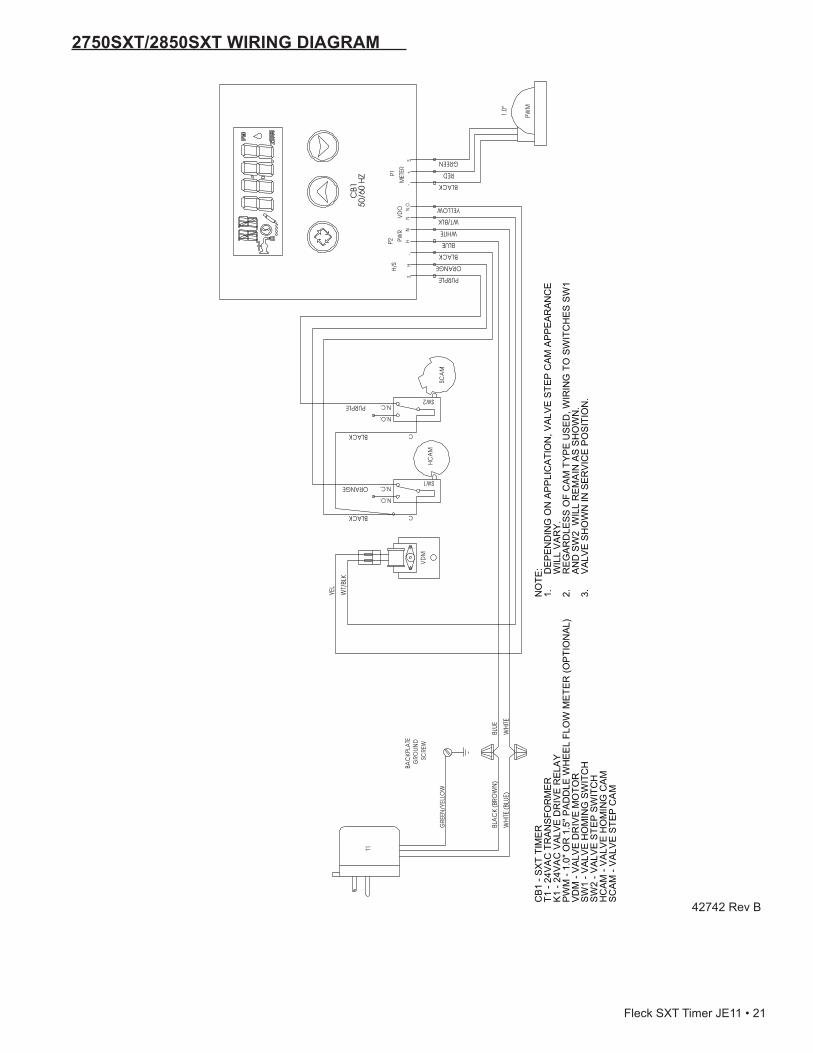
2750SXT/2850SXTWIRINGDIAGRAM
SCA
M
HC
AM
C
N.O.
N.C.SW2
C
N.O.
N.C.SW1
VD
M
PWM
1.0"
T1
H-
-S
WHITENN
GREEN
PURPLE
ORANGE
WH
ITE
YEL
S
PWR
VD
OM
ETER +
BLUE
WT/
BLK
BLUE
BLACK
HN
.O.
P2
RED
BLACK
P1
BLACK
ORANGE
BLACK
PURPLE
WT/BLK
YELLOW
WH
ITE (B
LUE)
H/S
BLA
CK
(BRO
WN
)
BAC
KPLA
TE
GRO
UN
D
SC
REW
GRE
EN/Y
ELLO
W
CB1
50/6
0 H
Z
CB
1 - S
XT
TIM
ER
T1 -
24V
AC
TR
AN
SFO
RM
ERK
1 - 2
4VA
C V
ALVE
DR
IVE
REL
AY
PW
M -
1.0"
OR
1.5
" PAD
DLE
WH
EE
L FL
OW
ME
TER
(OP
TIO
NAL
)VD
M -
VALV
E D
RIV
E M
OTO
RS
W1
- VAL
VE H
OM
ING
SW
ITC
HS
W2
- VA
LVE
STE
P S
WIT
CH
HC
AM -
VALV
E H
OM
ING
CA
MS
CA
M -
VA
LVE
STE
P C
AM
NO
TE: DEP
END
ING
ON
AP
PLI
CA
TIO
N, V
ALV
E S
TEP
CAM
APP
EAR
ANC
E
1.W
ILL
VA
RY
.R
EGAR
DLE
SS O
F C
AM T
YPE
USE
D, W
IRIN
G T
O S
WIT
CH
ES S
W1
2.AN
D S
W2
WIL
L R
EMA
IN A
S S
HO
WN
.V
ALV
E S
HO
WN
IN S
ERV
ICE
PO
SIT
ION
.3.
42742 Rev B
Fleck SXT Timer JE11 • 21

9000SXT/9100SXT/9500SXTWIRINGDIAGRAM
42743 Rev A
22 • JE11 Fleck SXT Timer

SERVICEASSEMBLIESMeter60086-50 ....................Meter Assy, 3/4", Electronic
2510/6600/670060613..........................Meter Assy, 2750 Electronic 1"60613-20 ....................Meter Assy, 2750, Electronic 1" BSP/
Metric60613NP .....................Meter Assy, 2750, Electronic 1" Nickel
Plated60614..........................Meter Assy, 2850/9500, Electronic 1-1/2"
Meter60614NP .....................Meter Assy, 2850/9500, Electronic 1-1/2"
Meter, NP60618..........................Meter Assy, Electronic, 3/4"60619-20 ....................Meter Assy, 1-1/2" Electronic BSP/Metric60626..........................Meter Assy, Turbine, Electronic 3/4" with
Clips and Screws60626-01 ....................Meter Assy, Turbine, 3/4" w/Clips,
Screws, Mtr/Cable61560-01 ....................Meter Assy, In-Line, w/1" NPT Plastic
Connector61560-02 ....................Meter Assy, In-Line, w/1" BSP Plastic
Connector61560-07 ....................Meter Assy, In-Line, w/1" NPT Brass
Connector61560-08 ....................Meter Assy, In-Line, w/1" BSP Brass
Connector61560-05 ....................Meter Assy, In-Line, w/1" I.D. & 1-1/4"
O.D. Sweat Connector61560-09 ....................Meter Assy, In-Line, w/ 1-1/2" NPT
Brass Connector61560-10 ....................Meter Assy, In-Line, w/ 1-1/2" BSP
Brass Connector
Fleck SXT Timer JE11 • 23

© 2011 Pentair Residential Filtration, LLC 42713 Rev F JE11