Supplemental Service Manual -...
75
SXT Timer Supplemental Service Manual IMPORTANT: Fill in Pertinent Information on Page 3 for Future Reference
Transcript of Supplemental Service Manual -...

SXT Timer
Supplemental Service Manual
IMPORTANT: Fill in Pertinent Information on Page 3 for Future Reference
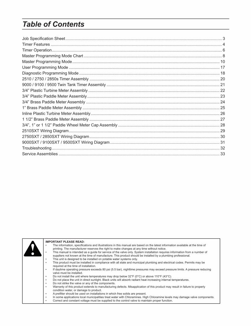
Job Specification Sheet ......................................................................................................................................... 3
Timer Features ...................................................................................................................................................... 4
Timer Operation ..................................................................................................................................................... 6
Master Programming Mode Chart ......................................................................................................................... 8
Master Programming Mode ................................................................................................................................. 10
User Programming Mode .................................................................................................................................... 17
Diagnostic Programming Mode ........................................................................................................................... 18
2510 / 2750 / 2850s Timer Assembly .................................................................................................................. 20
9000 / 9100 / 9500 Twin Tank Timer Assembly ................................................................................................... 21
3/4” Plastic Turbine Meter Assembly ................................................................................................................... 22
3/4” Plastic Paddle Meter Assembly .................................................................................................................... 23
3/4” Brass Paddle Meter Assembly ..................................................................................................................... 24
1” Brass Paddle Meter Assembly ........................................................................................................................ 25
Inline Plastic Turbine Meter Assembly ................................................................................................................. 26
1 1/2” Brass Paddle Meter Assembly .................................................................................................................. 27
3/4”, 1” or 1 1/2” Paddle Wheel Meter Cap Assembly ......................................................................................... 28
2510SXT Wiring Diagram .................................................................................................................................... 29
2750SXT / 2850SXT Wiring Diagram .................................................................................................................. 30
9000SXT / 9100SXT / 9500SXT Wiring Diagram ................................................................................................ 31
Troubleshooting ................................................................................................................................................... 32
Service Assemblies ............................................................................................................................................. 33
Table of Contents
IMPORTANT PLEASE READ:
The information, specifications and illustrations in this manual are based on the latest information available at the time of •
printing. The manufacturer reserves the right to make changes at any time without notice.
This manual is intended as a guide for service of the valve only. System installation requires information from a number of •
suppliers not known at the time of manufacture. This product should be installed by a plumbing professional.
This unit is designed to be installed on potable water systems only.•
This product must be installed in compliance with all state and municipal plumbing and electrical codes. Permits may be •
required at the time of installation.
If daytime operating pressure exceeds 80 psi (5.5 bar), nighttime pressures may exceed pressure limits. A pressure reducing •
valve must be installed.
Do not install the unit where temperatures may drop below 32°F (0°C) or above 110°F (43°C). •
Do not place the unit in direct sunlight. Black units will absorb radiant heat increasing internal temperatures. •
Do not strike the valve or any of the components.•
Warranty of this product extends to manufacturing defects. Misapplication of this product may result in failure to properly •
condition water, or damage to product.
A prefilter should be used on installations in which free solids are present. •
In some applications local municipalities treat water with Chloramines. High Chloramine levels may damage valve components.•
Correct and constant voltage must be supplied to the control valve to maintain proper function.•
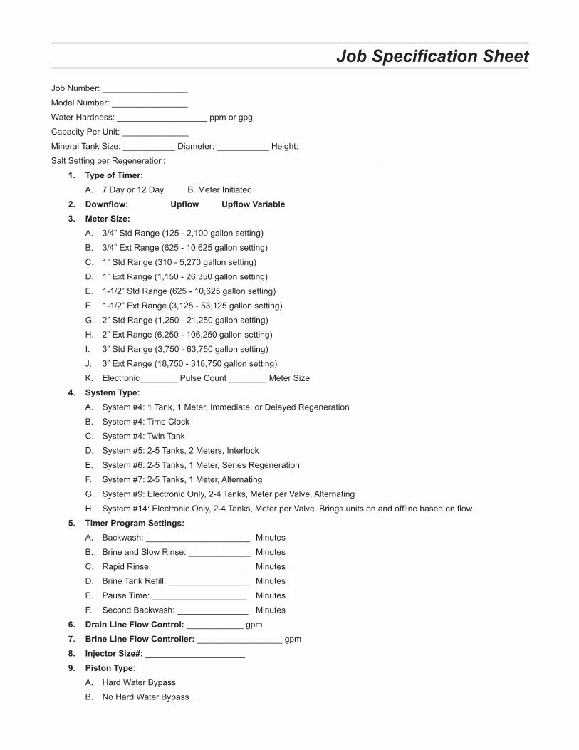
Job Number: __________________
Model Number: ________________
Water Hardness: ___________________ ppm or gpg
Capacity Per Unit: ______________
Mineral Tank Size: ___________ Diameter: ___________ Height:
Salt Setting per Regeneration: _____________________________________________
1. Type of Timer:
A. 7 Day or 12 Day B. Meter Initiated
2. Downflow: Upflow Upflow Variable
3. Meter Size:
A. 3/4” Std Range (125 - 2,100 gallon setting)
B. 3/4” Ext Range (625 - 10,625 gallon setting)
C. 1” Std Range (310 - 5,270 gallon setting)
D. 1” Ext Range (1,150 - 26,350 gallon setting)
E. 1-1/2” Std Range (625 - 10,625 gallon setting)
F. 1-1/2” Ext Range (3,125 - 53,125 gallon setting)
G. 2” Std Range (1,250 - 21,250 gallon setting)
H. 2” Ext Range (6,250 - 106,250 gallon setting)
I. 3” Std Range (3,750 - 63,750 gallon setting)
J. 3” Ext Range (18,750 - 318,750 gallon setting)
K. Electronic________ Pulse Count ________ Meter Size
4. System Type:
A. System #4: 1 Tank, 1 Meter, Immediate, or Delayed Regeneration
B. System #4: Time Clock
C. System #4: Twin Tank
D. System #5: 2-5 Tanks, 2 Meters, Interlock
E. System #6: 2-5 Tanks, 1 Meter, Series Regeneration
F. System #7: 2-5 Tanks, 1 Meter, Alternating
G. System #9: Electronic Only, 2-4 Tanks, Meter per Valve, Alternating
H. System #14: Electronic Only, 2-4 Tanks, Meter per Valve. Brings units on and offline based on flow.
5. Timer Program Settings:
A. Backwash: ______________________ Minutes
B. Brine and Slow Rinse: _____________ Minutes
C. Rapid Rinse: ____________________ Minutes
D. Brine Tank Refill: _________________ Minutes
E. Pause Time: ____________________ Minutes
F. Second Backwash: _______________ Minutes
6. Drain Line Flow Control: ____________ gpm
7. Brine Line Flow Controller: __________________ gpm
8. Injector Size#: _____________________
9. Piston Type:
A. Hard Water Bypass
B. No Hard Water Bypass
Job Specification Sheet

Page 4
Timer Features
Features of the SXT:Power backup that continues to keep time and the passage of days for a minimum of 48 hours in the event of •
power failure. During a power outage, the control goes into a power-saving mode. It does not monitor water
usage during a power failure, but it does store the volume remaining at the time of power failure.
Settings for both valve (basic system) and control type (method used to trigger a regeneration).•
Day-of-the-Week controls.•
While in service, the display alternates between time of day, volume remaining or days to regeneration, and •
tank in service (twin tank systems only).
The Flow Indicator flashes when outlet flow is detected.•
The Service Icon flashes if a regeneration cycle has been queued.•
A Regeneration can be triggered immediately by pressing the Extra Cycle button for five seconds.•
The Parameter Display displays the current Cycle Step (BW, BF, RR, etc) during regeneration, and the data •
display counts down the time remaining for that cycle step. While the valve is transferring to a new cycle step,
the display will flash. The parameter display will identify the destination cycle step (BW, BF, RR, etc) and the
data display will read “----”. Once the valve reaches the cycle step, the display will stop flashing and the data
display will change to the time remaining. During regeneration, the user can force the control to advance to
the next cycle step immediately by pressing the extra cycle button.
Setting the Time of DayPress and hold either the Up or Down buttons until the programming icon replaces the service icon and the 1.
parameter display reads TD.
Adjust the displayed time with the Up and Down buttons.2.
When the desired time is set, press the Extra Cycle button to resume normal operation. The unit will also 3.
return to normal operation after 5 seconds if no buttons are pressed.
ParameterDisplay
DataDisplay
PMIndicator
Flow Indicator
x1000 Indicator
Service
Icon
Programming
Icon
Extra Cycle
Button
Up
Button
Down
Button
Error/
Information
Icon
Page 5
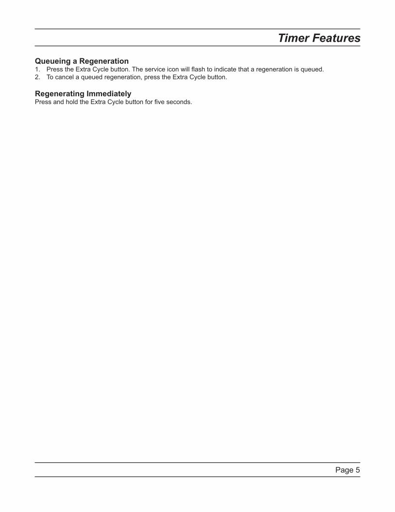
Timer Features
Queueing a RegenerationPress the Extra Cycle button. The service icon will flash to indicate that a regeneration is queued.1.
To cancel a queued regeneration, press the Extra Cycle button.2.
Regenerating ImmediatelyPress and hold the Extra Cycle button for five seconds.
Page 6
Timer Operation
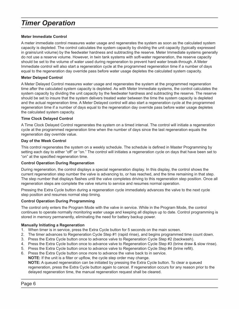
Meter Immediate Control
A meter immediate control measures water usage and regenerates the system as soon as the calculated system
capacity is depleted. The control calculates the system capacity by dividing the unit capacity (typically expressed
in grains/unit volume) by the feedwater hardness and subtracting the reserve. Meter Immediate systems generally
do not use a reserve volume. However, in twin tank systems with soft-water regeneration, the reserve capacity
should be set to the volume of water used during regeneration to prevent hard water break-through. A Meter
Immediate control will also start a regeneration cycle at the programmed regeneration time if a number of days
equal to the regeneration day override pass before water usage depletes the calculated system capacity.
Meter Delayed Control
A Meter Delayed Control measures water usage and regenerates the system at the programmed regeneration
time after the calculated system capacity is depleted. As with Meter Immediate systems, the control calculates the
system capacity by dividing the unit capacity by the feedwater hardness and subtracting the reserve. The reserve
should be set to insure that the system delivers treated water between the time the system capacity is depleted
and the actual regeneration time. A Meter Delayed control will also start a regeneration cycle at the programmed
regeneration time if a number of days equal to the regeneration day override pass before water usage depletes
the calculated system capacity.
Time Clock Delayed Control
A Time Clock Delayed Control regenerates the system on a timed interval. The control will initiate a regeneration
cycle at the programmed regeneration time when the number of days since the last regeneration equals the
regeneration day override value.
Day of the Week Control
This control regenerates the system on a weekly schedule. The schedule is defined in Master Programming by
setting each day to either “off” or “on.” The control will initiates a regeneration cycle on days that have been set to
“on” at the specified regeneration time.
Control Operation During Regeneration
During regeneration, the control displays a special regeneration display. In this display, the control shows the
current regeneration step number the valve is advancing to, or has reached, and the time remaining in that step.
The step number that displays flashes until the valve completes driving to this regeneration step position. Once all
regeneration steps are complete the valve returns to service and resumes normal operation.
Pressing the Extra Cycle button during a regeneration cycle immediately advances the valve to the next cycle
step position and resumes normal step timing.
Control Operation During Programming
The control only enters the Program Mode with the valve in service. While in the Program Mode, the control
continues to operate normally monitoring water usage and keeping all displays up to date. Control programming is
stored in memory permanently, eliminating the need for battery backup power.
Manually Initiating a Regeneration
When timer is in service, press the Extra Cycle button for 5 seconds on the main screen.1.
The timer advances to Regeneration Cycle Step #1 (rapid rinse), and begins programmed time count down.2.
Press the Extra Cycle button once to advance valve to Regeneration Cycle Step #2 (backwash).3.
Press the Extra Cycle button once to advance valve to Regeneration Cycle Step #3 (brine draw & slow rinse).4.
Press the Extra Cycle button once to advance valve to Regeneration Cycle Step #4 (brine refill).5.
Press the Extra Cycle button once more to advance the valve back to in service. 6.
NOTE: If the unit is a filter or upflow, the cycle step order may change.
NOTE: A queued regeneration can be initiated by pressing the Extra Cycle button. To clear a queued
regeneration, press the Extra Cycle button again to cancel. If regeneration occurs for any reason prior to the
delayed regeneration time, the manual regeneration request shall be cleared.

Page 7
Timer Operation
Control Operation During A Power Failure
The SXT includes integral power backup. In the event of power failure, the control shifts into a power-saving
mode. The control stops monitoring water usage, and the display and motor shut down, but it continues to keep
track of the time and day for a minimum of 48 hours.
The system configuration settings are stored in a non-volatile memory and are stored indefinitely with or without
line power. The Time of Day flashes when there has been a power failure. Press any button to stop the Time of
Day from flashing.
If power fails while the unit is in regeneration, the control will save the current valve position before it shuts down.
When power is restored, the control will resume the regeneration cycle from the point where power failed. Note
that if power fails during a regeneration cycle, the valve will remain in it’s current position until power is restored.
The valve system should include all required safety components to prevent overflows resulting from a power
failure during regeneration.
The control will not start a new regeneration cycle without line power. If the valve misses a scheduled
regeneration due to a power failure, it will queue a regeneration. Once power is restored, the control will initiate
a regeneration cycle the next time that the Time of Day equals the programmed regeneration time. Typically,
this means that the valve will regenerate one day after it was originally scheduled. If the treated water output is
important and power interruptions are expected, the system should be setup with a sufficient reserve capacity to
compensate for regeneration delays.
Page 8
Master Programming Mode Chart
CAUTION: Before entering Master Programming, please contact your local professional water dealer.
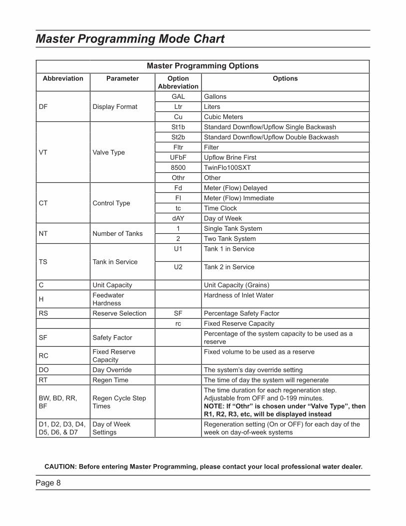
Master Programming Options
Abbreviation Parameter Option
Abbreviation
Options
DF Display Format
GAL Gallons
Ltr Liters
Cu Cubic Meters
VT Valve Type
St1b Standard Downflow/Upflow Single Backwash
St2b Standard Downflow/Upflow Double Backwash
Fltr Filter
UFbF Upflow Brine First
8500 TwinFlo100SXT
Othr Other
CT Control Type
Fd Meter (Flow) Delayed
FI Meter (Flow) Immediate
tc Time Clock
dAY Day of Week
NT Number of Tanks1 Single Tank System
2 Two Tank System
TS Tank in Service
U1 Tank 1 in Service
U2 Tank 2 in Service
C Unit Capacity Unit Capacity (Grains)
HFeedwater
Hardness
Hardness of Inlet Water
RS Reserve Selection SF Percentage Safety Factor
rc Fixed Reserve Capacity
SF Safety FactorPercentage of the system capacity to be used as a
reserve
RCFixed Reserve
Capacity
Fixed volume to be used as a reserve
DO Day Override The system’s day override setting
RT Regen Time The time of day the system will regenerate
BW, BD, RR,
BF
Regen Cycle Step
Times
The time duration for each regeneration step.
Adjustable from OFF and 0-199 minutes.
NOTE: If “Othr” is chosen under “Valve Type”, then
R1, R2, R3, etc, will be displayed instead
D1, D2, D3, D4,
D5, D6, & D7
Day of Week
Settings
Regeneration setting (On or OFF) for each day of the
week on day-of-week systems

Page 9
Master Programming Mode Chart
CAUTION: Before entering Master Programming, please contact your local professional water dealer.
Master Programming Options
CD Current Day The Current day of the week
FM Flow Meter Type
t0.7 3/4” Turbine Meter
P0.7 3/4” Paddle Wheel Meter
t1.0 1” Turbine Meter
P1.0 1” Paddle Wheel Meter
t1.5 1.5” Turbine Meter
P1.5 1.5” Paddle Wheel Meter
Gen Generic or Other Meter
K Meter Pulse Setting Meter pulses per gallon for generic/other flow meter
NOTES:
Some items may not be shown depending on timer configuration.
The timer will discard any changes and exit Master Programming Mode if any button is not pressed for
sixty seconds.

Page 10
Master Programming Mode
CAUTION: Before entering Master Programming, please contact your local professional water dealer.
When the Master Programming Mode is entered, all available option setting displays may be viewed and set as
needed. Depending on current option settings, some parameters cannot be viewed or set.
Setting the Time of DayPress and hold either the Up or Down buttons until the programming icon replaces the service icon and the 1.
parameter display reads TD.
Adjust the displayed time with the Up and Down buttons.2.
3. When the desired time is set, press the Extra Cycle button to resume normal operation. The unit will also
return to normal operation after 5 seconds if no buttons are pressed.
Entering Master Programming ModeSet the Time Of Day display to 12:01 P.M. Press the Extra Cycle button (to exit Setting Time of Day mode). Then
press and hold the Up and Down buttons together until the programming icon replaces the service icon and the
Display Format screen appears.
Exiting Master Programming ModePress the Extra Cycle button to accept the displayed settings and cycle to the next parameter. Press the
Extra Cycle button at the last parameter to save all settings and return to normal operation. The control
will automatically disregard any programming changes and return to normal operation if it is left in Master
Programming mode for 5 minutes without any keypad input.
Resets:
Soft Reset: Press and hold the Extra Cycle and Down buttons for 25 seconds while in normal Service mode.
This resets all parameters to the system default values, except the volume remaining in meter immediate or meter
delayed systems and days since regeneration in the time clock system.
Master Reset: Hold the Extra Cycle button while powering up the unit. This resets all of the parameters in the
unit. Check and verify the choices selected in Master Programming Mode.
1. Display Format (Display Code DF)This is the first screen that appears when entering Master Programming Mode. The Display Format setting
specifies the unit of measure that will be used for volume and how the control will display the Time of Day. This
option setting is identified by “DF” in the upper left hand corner of the screen. There are three possible settings:
Display Format Setting Unit of Volume Time Display
GAL U.S. Gallons 12-Hour AM/PM
Ltr Liters 24-Hour
Cu Cubic Meters 24-Hour
Page 11
Master Programming Mode
CAUTION: Before entering Master Programming, please contact your local professional water dealer.
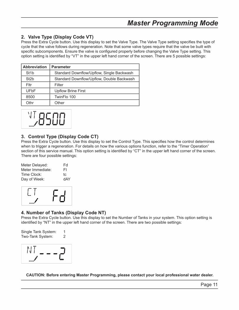
2. Valve Type (Display Code VT)Press the Extra Cycle button. Use this display to set the Valve Type. The Valve Type setting specifies the type of
cycle that the valve follows during regeneration. Note that some valve types require that the valve be built with
specific subcomponents. Ensure the valve is configured properly before changing the Valve Type setting. This
option setting is identified by “VT” in the upper left hand corner of the screen. There are 5 possible settings:
Abbreviation Parameter
St1b Standard Downflow/Upflow, Single Backwash
St2b Standard Downflow/Upflow, Double Backwash
Fltr Filter
UFbF Upflow Brine First
8500 TwinFlo 100
Othr Other
3. Control Type (Display Code CT)Press the Extra Cycle button. Use this display to set the Control Type. This specifies how the control determines
when to trigger a regeneration. For details on how the various options function, refer to the “Timer Operation”
section of this service manual. This option setting is identified by “CT” in the upper left hand corner of the screen.
There are four possible settings:
Meter Delayed: Fd
Meter Immediate: FI
Time Clock: tc
Day of Week: dAY
4. Number of Tanks (Display Code NT)Press the Extra Cycle button. Use this display to set the Number of Tanks in your system. This option setting is
identified by “NT” in the upper left hand corner of the screen. There are two possible settings:
Single Tank System: 1
Two-Tank System: 2
Page 12
Master Programming Mode
CAUTION: Before entering Master Programming, please contact your local professional water dealer.
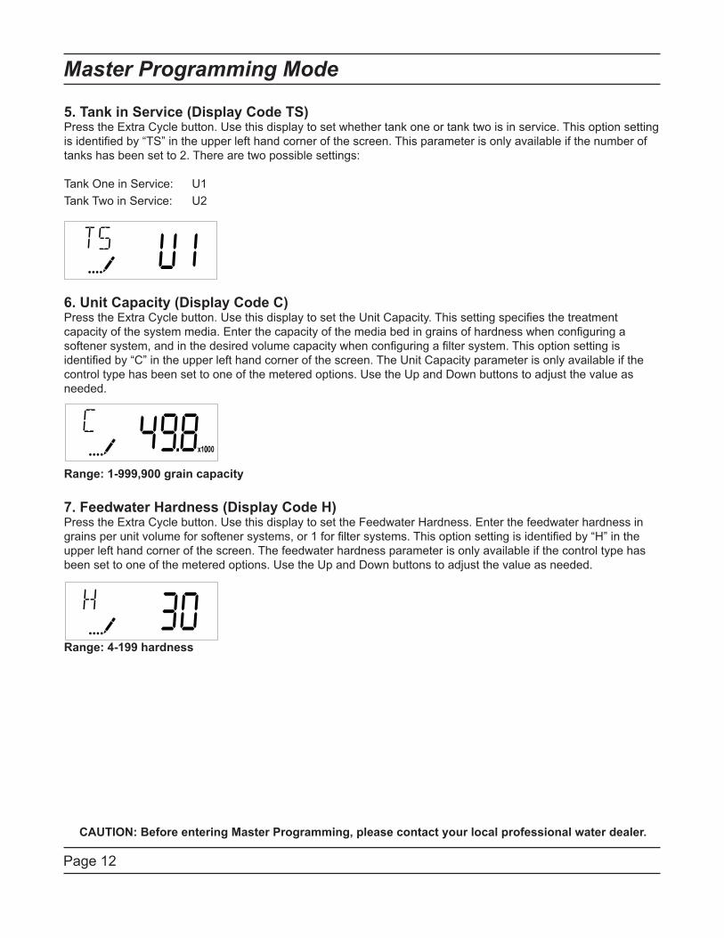
5. Tank in Service (Display Code TS)Press the Extra Cycle button. Use this display to set whether tank one or tank two is in service. This option setting
is identified by “TS” in the upper left hand corner of the screen. This parameter is only available if the number of
tanks has been set to 2. There are two possible settings:
Tank One in Service: U1
Tank Two in Service: U2
6. Unit Capacity (Display Code C)Press the Extra Cycle button. Use this display to set the Unit Capacity. This setting specifies the treatment
capacity of the system media. Enter the capacity of the media bed in grains of hardness when configuring a
softener system, and in the desired volume capacity when configuring a filter system. This option setting is
identified by “C” in the upper left hand corner of the screen. The Unit Capacity parameter is only available if the
control type has been set to one of the metered options. Use the Up and Down buttons to adjust the value as
needed.
Range: 1-999,900 grain capacity
7. Feedwater Hardness (Display Code H)Press the Extra Cycle button. Use this display to set the Feedwater Hardness. Enter the feedwater hardness in
grains per unit volume for softener systems, or 1 for filter systems. This option setting is identified by “H” in the
upper left hand corner of the screen. The feedwater hardness parameter is only available if the control type has
been set to one of the metered options. Use the Up and Down buttons to adjust the value as needed.
Range: 4-199 hardness
Page 13
Master Programming Mode
CAUTION: Before entering Master Programming, please contact your local professional water dealer.
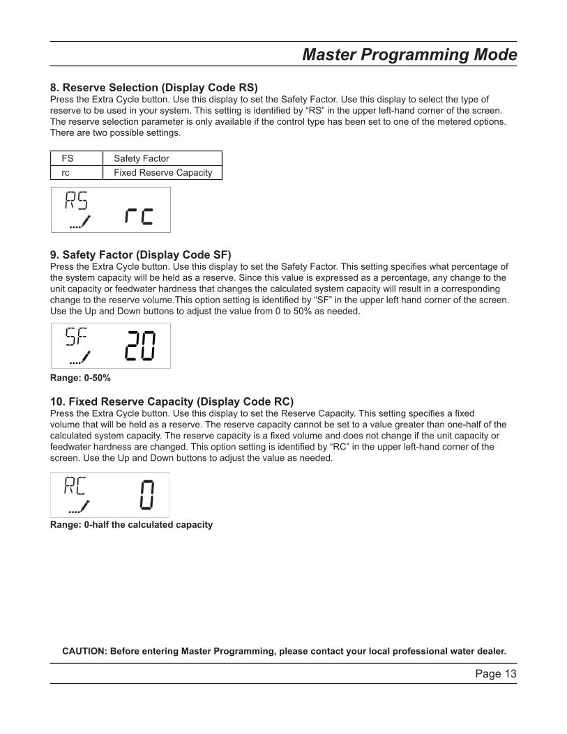
8. Reserve Selection (Display Code RS)Press the Extra Cycle button. Use this display to set the Safety Factor. Use this display to select the type of
reserve to be used in your system. This setting is identified by “RS” in the upper left-hand corner of the screen.
The reserve selection parameter is only available if the control type has been set to one of the metered options.
There are two possible settings.
FS Safety Factor
rc Fixed Reserve Capacity
9. Safety Factor (Display Code SF)Press the Extra Cycle button. Use this display to set the Safety Factor. This setting specifies what percentage of
the system capacity will be held as a reserve. Since this value is expressed as a percentage, any change to the
unit capacity or feedwater hardness that changes the calculated system capacity will result in a corresponding
change to the reserve volume.This option setting is identified by “SF” in the upper left hand corner of the screen.
Use the Up and Down buttons to adjust the value from 0 to 50% as needed.
Range: 0-50%
10. Fixed Reserve Capacity (Display Code RC)Press the Extra Cycle button. Use this display to set the Reserve Capacity. This setting specifies a fixed
volume that will be held as a reserve. The reserve capacity cannot be set to a value greater than one-half of the
calculated system capacity. The reserve capacity is a fixed volume and does not change if the unit capacity or
feedwater hardness are changed. This option setting is identified by “RC” in the upper left-hand corner of the
screen. Use the Up and Down buttons to adjust the value as needed.
Range: 0-half the calculated capacity
Page 14
Master Programming Mode
CAUTION: Before entering Master Programming, please contact your local professional water dealer.
11. Day Override (Display Code DO)Press the Extra Cycle button. Use this display to set the Day Override. This setting specifies the maximum
number of days between regeneration cycles. If the system is set to a timer-type control, the day override setting
determines how often the system will regenerate. A metered system will regenerate regardless of usage if the
days since last regeneration cycle equal the day override setting. Setting the day override value to “OFF” disables
this function. This option setting is identified by “DO” in the upper left hand corner of the screen. Use the Up and
Down buttons to adjust the value as needed.
Range: Off-99 days
12. Regeneration TimePress the Extra Cycle button. Use this display to set the Regeneration Time. This setting specifies the time of day
the control will initiate a delayed, manually queued, or day override triggered regeneration. This option setting is
identified by “RT” in the upper left hand corner of the screen. Use the Up and Down buttons to adjust the value as
needed.
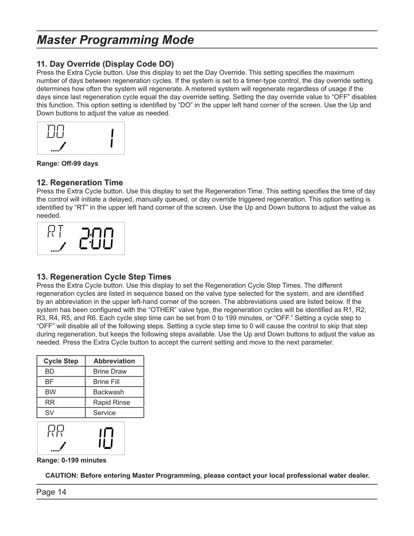
13. Regeneration Cycle Step TimesPress the Extra Cycle button. Use this display to set the Regeneration Cycle Step Times. The different
regeneration cycles are listed in sequence based on the valve type selected for the system, and are identified
by an abbreviation in the upper left-hand corner of the screen. The abbreviations used are listed below. If the
system has been configured with the “OTHER” valve type, the regeneration cycles will be identified as R1, R2,
R3, R4, R5, and R6. Each cycle step time can be set from 0 to 199 minutes, or “OFF.” Setting a cycle step to
“OFF” will disable all of the following steps. Setting a cycle step time to 0 will cause the control to skip that step
during regeneration, but keeps the following steps available. Use the Up and Down buttons to adjust the value as
needed. Press the Extra Cycle button to accept the current setting and move to the next parameter.
Cycle Step Abbreviation
BD Brine Draw
BF Brine Fill
BW Backwash
RR Rapid Rinse
SV Service
Range: 0-199 minutes
Page 15
Master Programming Mode
CAUTION: Before entering Master Programming, please contact your local professional water dealer.
14. Day of Week SettingsPress the Extra Cycle button. Use this display to set the regeneration schedule for a system configured as a Day
of Week control. The different days of the week are identified as D1, D2, D3, D4, D5, D6, and D7 in the upper
left-hand corner of the display. Set the value to “ON” to schedule a regeneration or “OFF” to skip regeneration for
each day. Use the Up and Down buttons to adjust the setting as needed. Press the Extra Cycle button to accept
the setting and move to the next day. Note that the control requires at least one day to be set to “ON.” If all 7 days
are set to “OFF”, the unit will return to Day One until one or more days are set to “ON.”
15. Current Day (Display Code CD)Press the Extra Cycle button. Use this display to set the current day on systems that have been configured as
Day of Week controls. This setting is identified by “CD” in the upper left-hand corner of the screen. Use the Up
and Down buttons to select from Day 1 through Day 7.
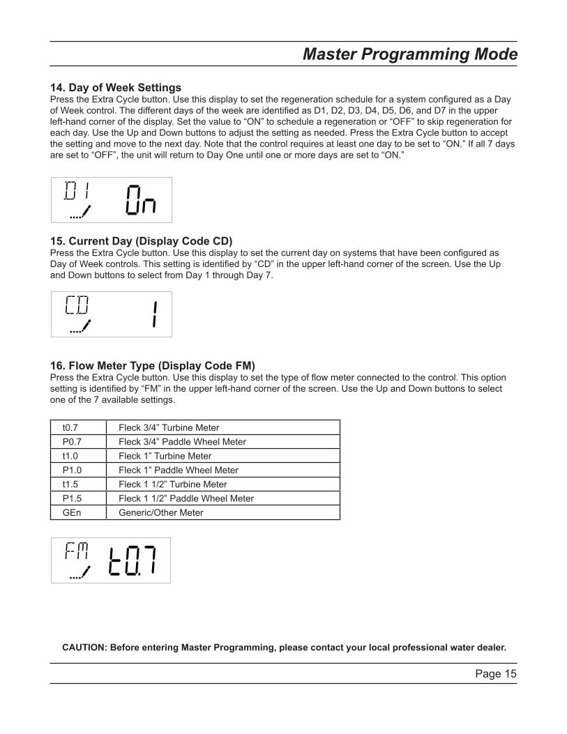
16. Flow Meter Type (Display Code FM)Press the Extra Cycle button. Use this display to set the type of flow meter connected to the control. This option
setting is identified by “FM” in the upper left-hand corner of the screen. Use the Up and Down buttons to select
one of the 7 available settings.
t0.7 Fleck 3/4” Turbine Meter
P0.7 Fleck 3/4” Paddle Wheel Meter
t1.0 Fleck 1” Turbine Meter
P1.0 Fleck 1” Paddle Wheel Meter
t1.5 Fleck 1 1/2” Turbine Meter
P1.5 Fleck 1 1/2” Paddle Wheel Meter
GEn Generic/Other Meter
Page 16
Master Programming Mode
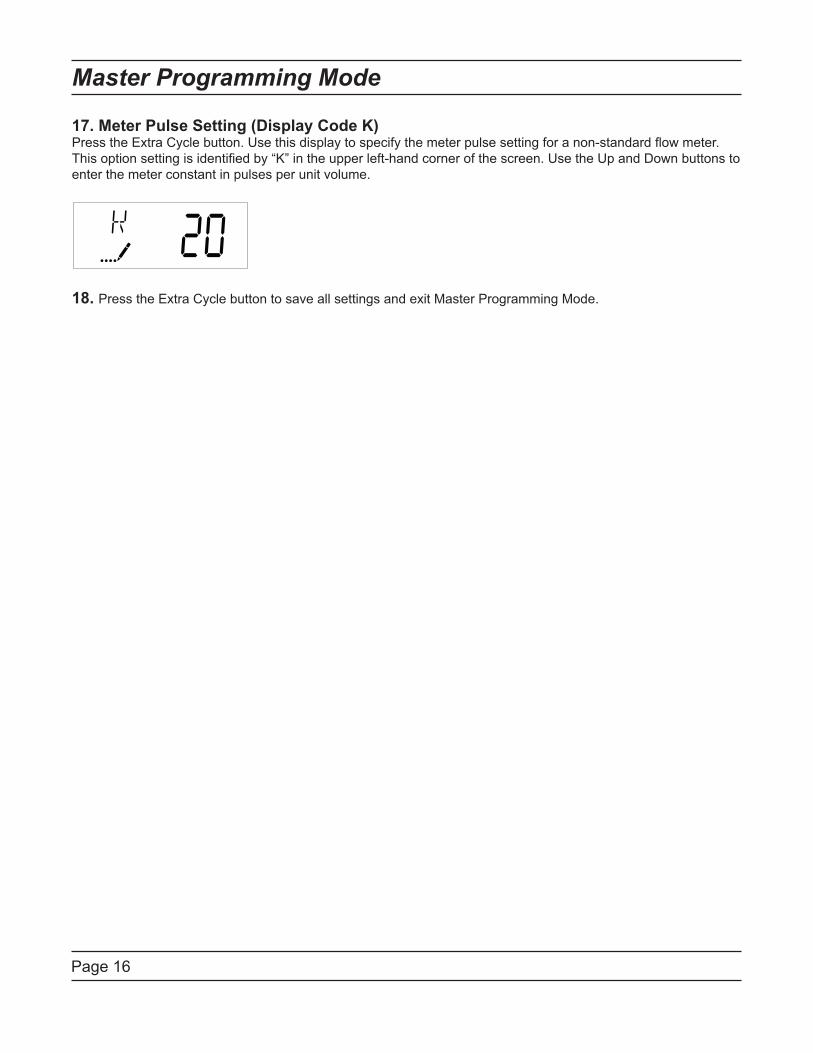
17. Meter Pulse Setting (Display Code K)Press the Extra Cycle button. Use this display to specify the meter pulse setting for a non-standard flow meter.
This option setting is identified by “K” in the upper left-hand corner of the screen. Use the Up and Down buttons to
enter the meter constant in pulses per unit volume.
18. Press the Extra Cycle button to save all settings and exit Master Programming Mode.
Page 17
User Programming Mode
User Programming Mode Options
Abbreviation Parameter Description
DO Day Override The timer’s day override setting
RT Regeneration Time The time of day that the system
will regenerate (meter delayed,
timeclock, and day-of-week
systems)
H Feed Water Hardness The hardness of the inlet water -
used to calculate system capacity
for metered systems
RC Reserve Capacity The fixed reserve capacity
CD Current Day The current day of week
NOTES:
Some items may not be shown depending on timer configuration.
The timer will discard any changes and exit User Mode if any button is not pressed for sixty seconds.
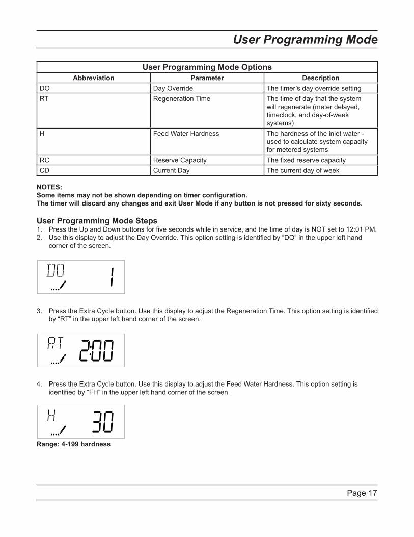
User Programming Mode StepsPress the Up and Down buttons for five seconds while in service, and the time of day is NOT set to 12:01 PM.1.
Use this display to adjust the Day Override. This option setting is identified by “DO” in the upper left hand 2.
corner of the screen.
Press the Extra Cycle button. Use this display to adjust the Regeneration Time. This option setting is identified 3.
by “RT” in the upper left hand corner of the screen.
Press the Extra Cycle button. Use this display to adjust the Feed Water Hardness. This option setting is 4.
identified by “FH” in the upper left hand corner of the screen.
Range: 4-199 hardness
Page 18
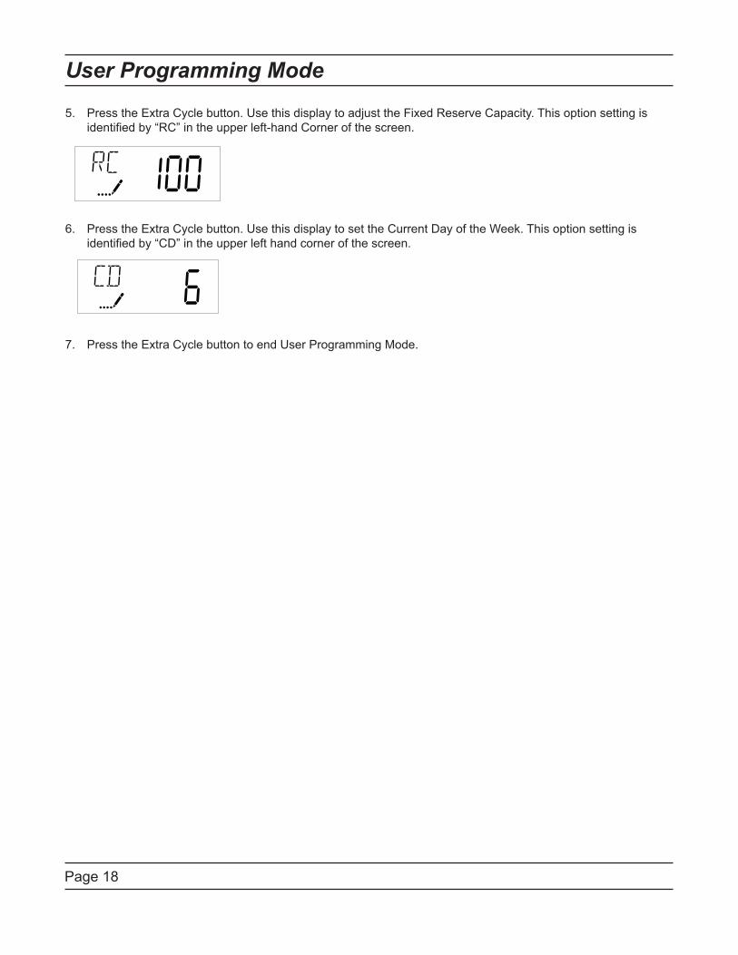
Press the Extra Cycle button. Use this display to adjust the Fixed Reserve Capacity. This option setting is 5.
identified by “RC” in the upper left-hand Corner of the screen.
Press the Extra Cycle button. Use this display to set the Current Day of the Week. This option setting is 6.
identified by “CD” in the upper left hand corner of the screen.
Press the Extra Cycle button to end User Programming Mode.7.
User Programming Mode

Page 19
Diagnostic Programming Mode
Diagnostic Programming Mode Options
Abbreviation Parameter Description
FR Flow Rate Displays the current outlet flow rate
PF Peak Flow Rate Displays the highest flow rate measured since the last regeneration
HR Hours in Service Displays the total hours that the unit has been in service
VU Volume Used Displays the total volume of water treated by the unit
RC Reserve Capacity Displays the system’s reserve capacity calculated from the system
capacity, feedwater hardness, and safety factor
SV Software Version Displays the software version installed on the controller
NOTES:
Some items may not be shown depending on timer configuration.
The timer will exit Diagnostic Mode after 60 seconds if no buttons are pressed.
Press the Extra Cycle button to exit Diagnostic Mode at any time.
Diagnostic Programming Mode StepsPress the Up and Extra Cycle buttons for five seconds while in service.1.
Use this display to view the current Flow Rate. This option setting is identified by “FR” in the upper left hand 2.
corner of the screen.
Press the Up button. Use this display to view the Peak Flow Rate since the last regeneration cycle. This 3.
option setting is identified by “PF” in the upper left hand corner of the screen.
Press the Up button. Use this display to view the Hours in Service since the last regeneration cycle. This 4.
option setting is identified by “HR” in the upper left hand corner of the screen.
Press the Up button. Use this display to view the Volume Used since the last regeneration cycle. This option 5.
setting is identified by “VU” in the upper left hand corner of the screen.
Page 20
Diagnostic Programming Mode
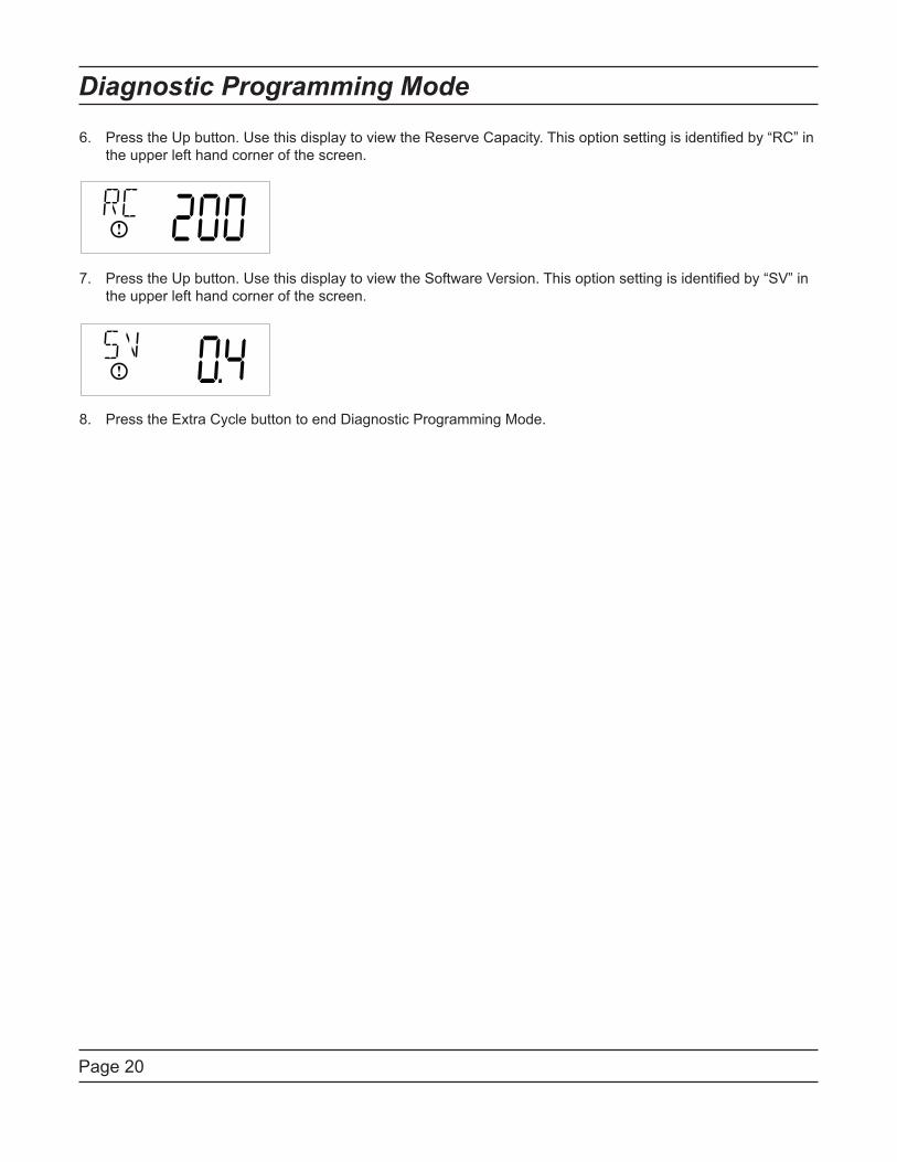
Press the Up button. Use this display to view the Reserve Capacity. This option setting is identified by “RC” in 6.
the upper left hand corner of the screen.
Press the Up button. Use this display to view the Software Version. This option setting is identified by “SV” in 7.
the upper left hand corner of the screen.
Press the Extra Cycle button to end Diagnostic Programming Mode.8.
Page 21
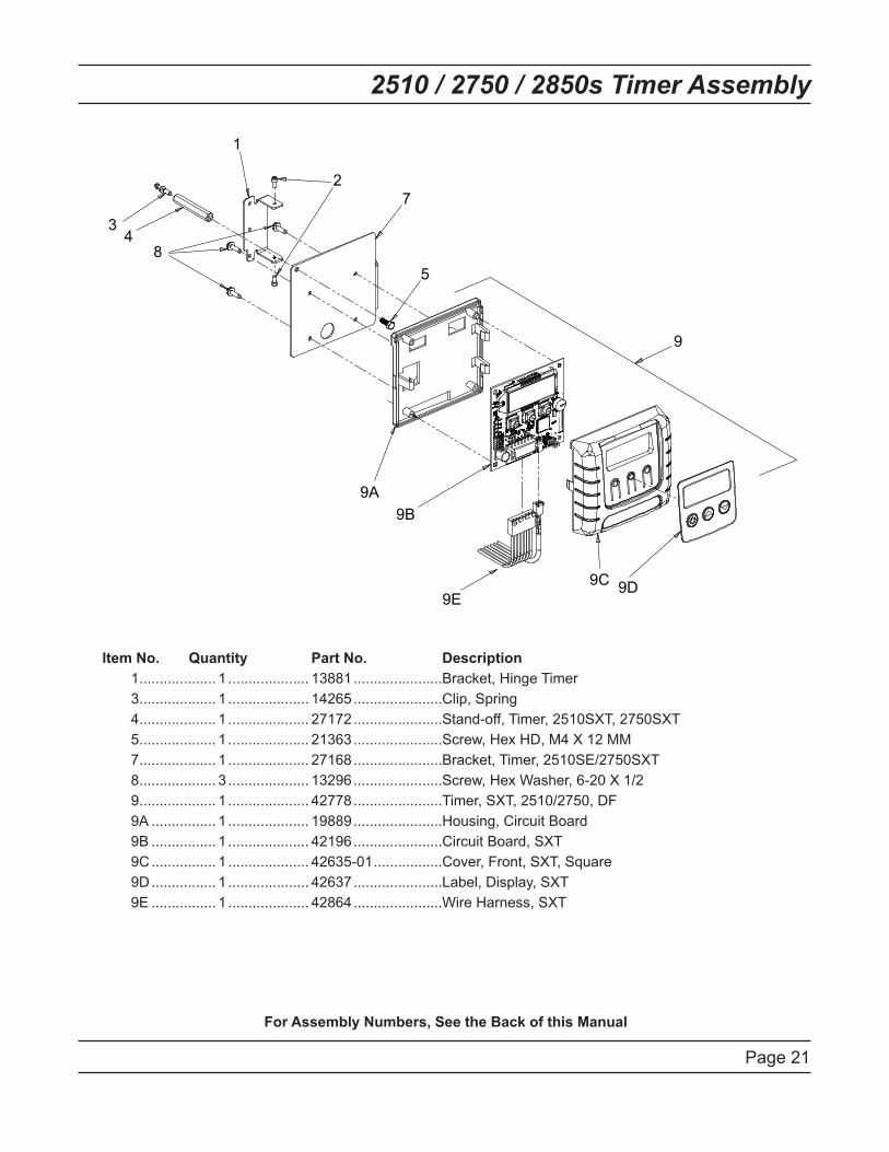
2510 / 2750 / 2850s Timer Assembly
Item No. Quantity Part No. Description
1 ................... 1 .................... 13881 ......................Bracket, Hinge Timer
3 ................... 1 .................... 14265 ......................Clip, Spring
4 ................... 1 .................... 27172 ......................Stand-off, Timer, 2510SXT, 2750SXT
5 ................... 1 .................... 21363 ......................Screw, Hex HD, M4 X 12 MM
7 ................... 1 .................... 27168 ......................Bracket, Timer, 2510SE/2750SXT
8 ................... 3 .................... 13296 ......................Screw, Hex Washer, 6-20 X 1/2
9 ................... 1 .................... 42778 ......................Timer, SXT, 2510/2750, DF
9A ................ 1 .................... 19889 ......................Housing, Circuit Board
9B ................ 1 .................... 42196 ......................Circuit Board, SXT
9C ................ 1 .................... 42635-01 .................Cover, Front, SXT, Square
9D ................ 1 .................... 42637 ......................Label, Display, SXT
9E ................ 1 .................... 42864 ......................Wire Harness, SXT
For Assembly Numbers, See the Back of this Manual
9
3 4
1
2
7
5
9A
9B
9C 9D
8
9E
Page 22
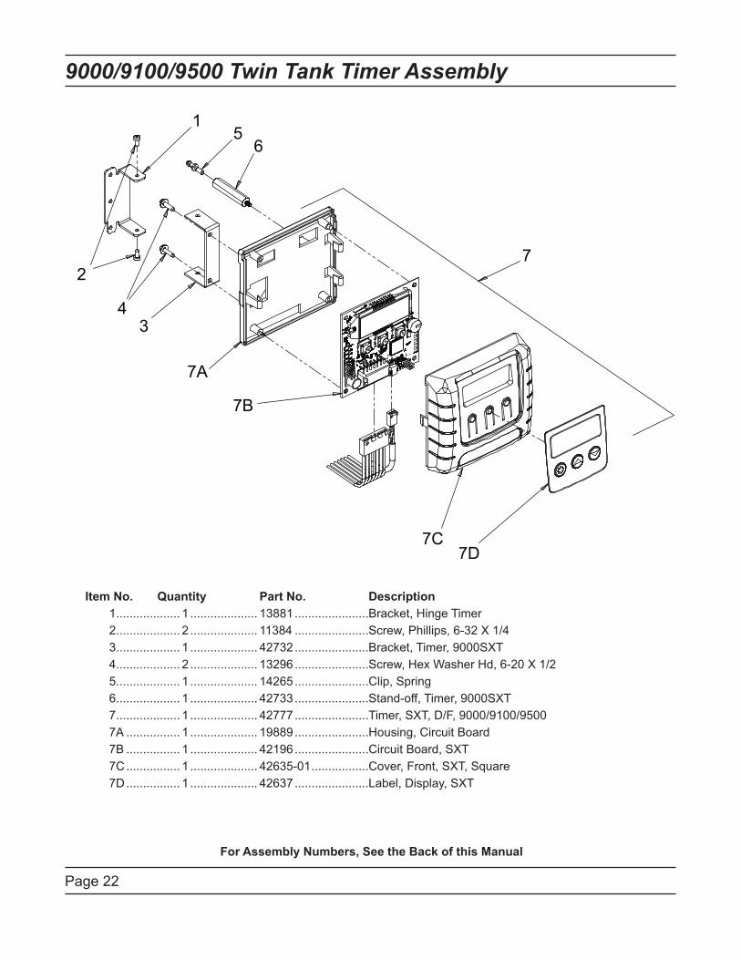
9000/9100/9500 Twin Tank Timer Assembly
Item No. Quantity Part No. Description
1 ................... 1 .................... 13881 ......................Bracket, Hinge Timer
2 ................... 2 .................... 11384 ......................Screw, Phillips, 6-32 X 1/4
3 ................... 1 .................... 42732 ......................Bracket, Timer, 9000SXT
4 ................... 2 .................... 13296 ......................Screw, Hex Washer Hd, 6-20 X 1/2
5 ................... 1 .................... 14265 ......................Clip, Spring
6 ................... 1 .................... 42733 ......................Stand-off, Timer, 9000SXT
7 ................... 1 .................... 42777 ......................Timer, SXT, D/F, 9000/9100/9500
7A ................ 1 .................... 19889 ......................Housing, Circuit Board
7B ................ 1 .................... 42196 ......................Circuit Board, SXT
7C ................ 1 .................... 42635-01 .................Cover, Front, SXT, Square
7D ................ 1 .................... 42637 ......................Label, Display, SXT
For Assembly Numbers, See the Back of this Manual
1
2
43
56
7A
7B
7C7D
7
Page 23
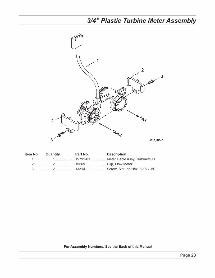
3/4” Plastic Turbine Meter Assembly
Item No. Quantity Part No. Description
1 ................... 1 .................... 19791-01 .................Meter Cable Assy, Turbine/SXT
2 ................... 2 .................... 19569 ......................Clip, Flow Meter
3 ................... 2 .................... 13314 ......................Screw, Slot Ind Hex, 8-18 x .60
For Assembly Numbers, See the Back of this Manual
Page 24
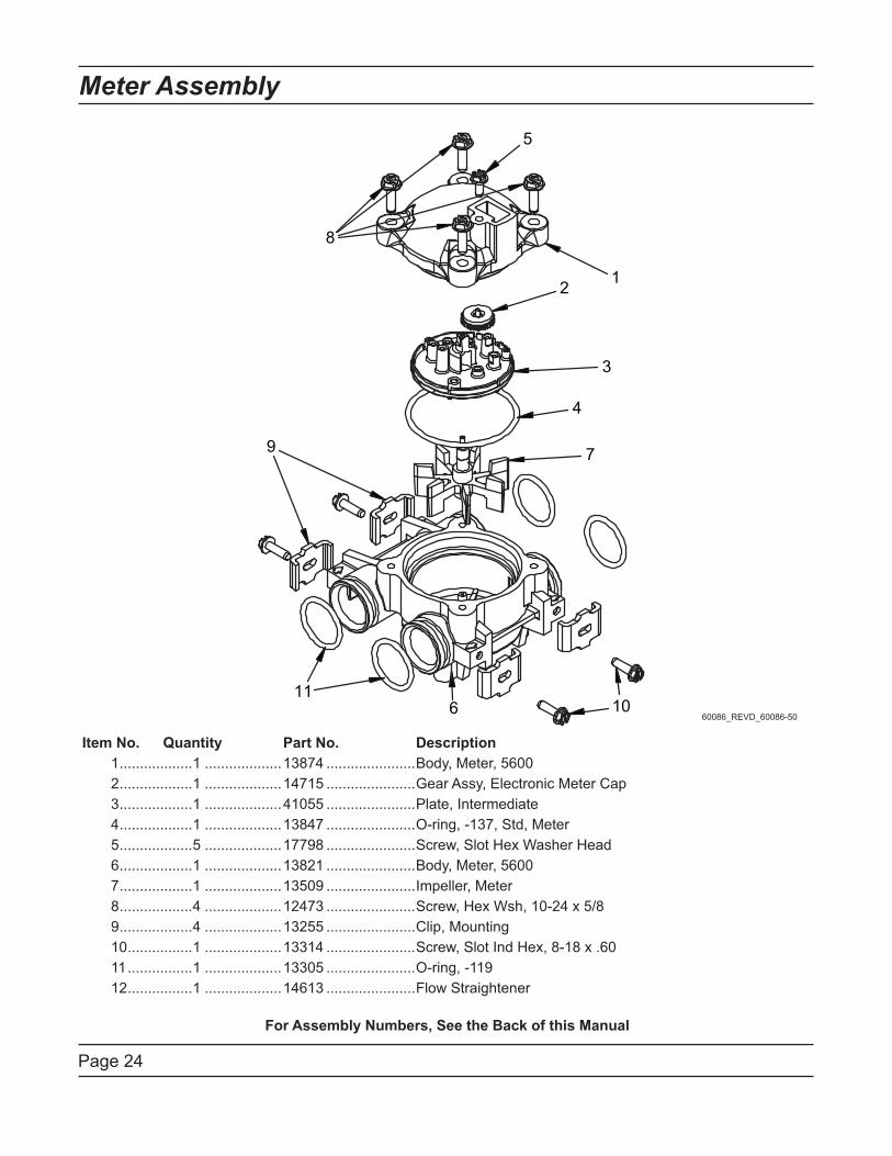
Meter Assembly
Item No. Quantity Part No. Description
1 ..................1 ...................13874 ......................Body, Meter, 5600
2 ..................1 ...................14715 ......................Gear Assy, Electronic Meter Cap
3 ..................1 ...................41055 ......................Plate, Intermediate
4 ..................1 ...................13847 ......................O-ring, -137, Std, Meter
5 ..................5 ...................17798 ......................Screw, Slot Hex Washer Head
6 ..................1 ...................13821 ......................Body, Meter, 5600
7 ..................1 ...................13509 ......................Impeller, Meter
8 ..................4 ...................12473 ......................Screw, Hex Wsh, 10-24 x 5/8
9 ..................4 ...................13255 ......................Clip, Mounting
10 ................1 ...................13314 ......................Screw, Slot Ind Hex, 8-18 x .60
11 ................1 ...................13305 ......................O-ring, -119
12 ................1 ...................14613 ......................Flow Straightener
For Assembly Numbers, See the Back of this Manual
60086_REVD_60086-50
Page 25
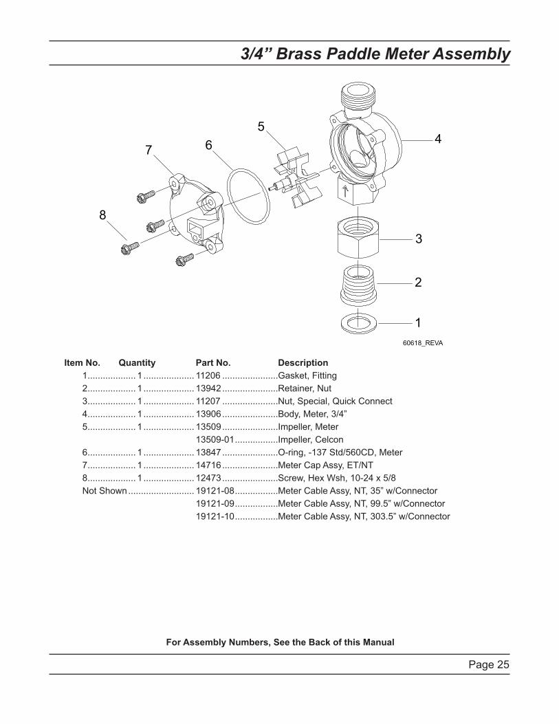
3/4” Brass Paddle Meter Assembly
Item No. Quantity Part No. Description
1 ................... 1 .................... 11206 ......................Gasket, Fitting
2 ................... 1 .................... 13942 ......................Retainer, Nut
3 ................... 1 .................... 11207 ......................Nut, Special, Quick Connect
4 ................... 1 .................... 13906 ......................Body, Meter, 3/4”
5 ................... 1 .................... 13509 ......................Impeller, Meter
13509-01 .................Impeller, Celcon
6 ................... 1 .................... 13847 ......................O-ring, -137 Std/560CD, Meter
7 ................... 1 .................... 14716 ......................Meter Cap Assy, ET/NT
8 ................... 1 .................... 12473 ......................Screw, Hex Wsh, 10-24 x 5/8
Not Shown .......................... 19121-08 .................Meter Cable Assy, NT, 35” w/Connector
19121-09 .................Meter Cable Assy, NT, 99.5” w/Connector
19121-10 .................Meter Cable Assy, NT, 303.5” w/Connector
For Assembly Numbers, See the Back of this Manual
Page 26
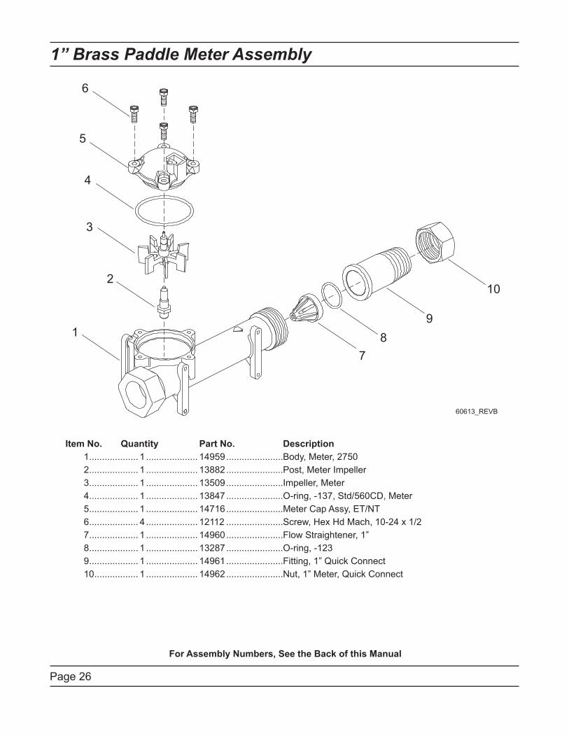
1” Brass Paddle Meter Assembly
Item No. Quantity Part No. Description
1 ................... 1 .................... 14959 ......................Body, Meter, 2750
2 ................... 1 .................... 13882 ......................Post, Meter Impeller
3 ................... 1 .................... 13509 ......................Impeller, Meter
4 ................... 1 .................... 13847 ......................O-ring, -137, Std/560CD, Meter
5 ................... 1 .................... 14716 ......................Meter Cap Assy, ET/NT
6 ................... 4 .................... 12112 ......................Screw, Hex Hd Mach, 10-24 x 1/2
7 ................... 1 .................... 14960 ......................Flow Straightener, 1”
8 ................... 1 .................... 13287 ......................O-ring, -123
9 ................... 1 .................... 14961 ......................Fitting, 1” Quick Connect
10 ................. 1 .................... 14962 ......................Nut, 1” Meter, Quick Connect
For Assembly Numbers, See the Back of this Manual

Page 27
Inline Plastic Turbine Meter Assembly
Item No. Quantity Part No. Description
1 ................... 1 .................... 17542 ......................Flow Straightener
2 ................... 2 .................... 40576 ......................Clip, H, Plastic, 7000
3 ................... 1 .................... 40577 ......................Turbine Meter Assy, 7000
4 ................... 1 .................... 41555 ......................Body, Remote Meter
5 ................... 2 .................... 40951 ......................O-ring, -220
6 ................... 2 .................... 40563 ......................Connector, 1” NPT, 7000
7 ................... 2 .................... 40563-10 .................Connector, 1” BSP, 7000
8 ................... 2 .................... 40565 ......................Connector, 1-1/4” NPT, 7000
9 ................... 2 .................... 40565-10 .................Connector, 1-1/4” BSP, 7000
10 ................. 2 .................... 41242 ......................Connector, 1” & 1-1/4” Sweat
11 ................. 2 .................... 41243 ......................Connector, 1-1/4 & 1-1/2” Sweat
12 ................. 2 .................... 41596 ......................Connector, Brass, 1” NPT
13 ................. 2 .................... 41596-10 .................Connector, Brass, 1” BSP
14 ................. 2 .................... 41597 ......................Connector, Brass, 1-1/2” NPT
15 ................. 2 .................... 41597-10 .................Connector, Brass, 1-1/2” BSP
For Assembly Numbers, See the Back of this Manual

Page 28
1-1/2” Brass Paddle Meter Assembly
Item No. Quantity Part No. Description
1 ................... 1 .................... 17569 ......................Body, Meter, 2850/9500
2 ................... 1 .................... 13882 ......................Post, Meter Impeller
3 ................... 1 .................... 13509 ......................Impeller, Meter
4 ................... 1 .................... 13847 ......................O-ring, -137, Std/560CD, Meter
5 ................... 1 .................... 14716 ......................Meter Cap Assy, NT
6 ................... 4 .................... 12112 ......................Screw, Hex Hd Mach, 10-24 x 1/2
7 ................... 1 .................... 17542 ......................Flow Straightener, 1-1/2”
8 ................... 1 .................... 12733 ......................O-ring, -132
9 ................... 1 .................... 17544 ......................Fitting, 1-1/2” Quick Connect
10 ................. 1 .................... 17543 ......................Nut, 1-1/2”, Quick Connect
For Assembly Numbers, See the Back of this Manual
Page 29
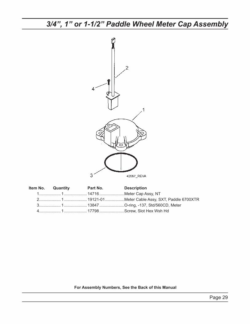
3/4”, 1” or 1-1/2” Paddle Wheel Meter Cap Assembly
Item No. Quantity Part No. Description
1 ................... 1 .................... 14716 ......................Meter Cap Assy, NT
2 ................... 1 .................... 19121-01 .................Meter Cable Assy, SXT, Paddle 6700XTR
3 ................... 1 .................... 13847 ......................O-ring, -137, Std/560CD, Meter
4 ................... 1 .................... 17798 ......................Screw, Slot Hex Wsh Hd
For Assembly Numbers, See the Back of this Manual
Page 3
0
251
0S
XT
Wirin
g D
iag
ram
SCAM
HCAM
C
N.O
.
N.C
.SW
2
C
N.O
.
N.C
.SW
1VDM
T1
H - - S
WH
ITE
N N
GR
EE
N
TM
PU
RP
LE
OR
AN
GE
WHITE
YEL
S
PWR VDO METER+
BLUE
WT/BLK
BLU
E
BLA
CK
H N.O.
P2
RE
D
BLA
CK
P1
BLA
CK
OR
AN
GE
BLA
CK
PU
RP
LE
WT/
BLK
YE
LLO
W
WHITE (BLUE)
H/S
BLACK (BROWN)
BACKPLATE
GROUND
SCREW
GREEN/YELLOW
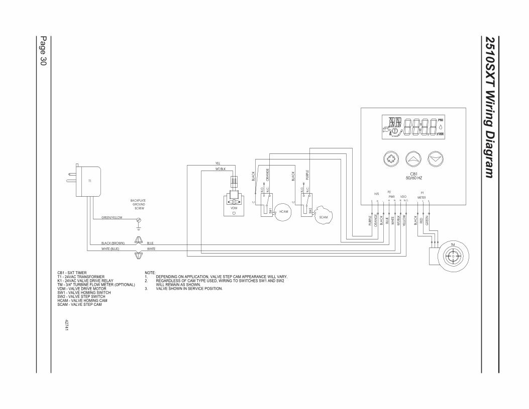
CB1 - SXT TIMERT1 - 24VAC TRANSFORMERK1 - 24VAC VALVE DRIVE RELAYTM - 3/4" TURBINE FLOW METER (OPTIONAL)VDM - VALVE DRIVE MOTORSW1 - VALVE HOMING SWITCHSW2 - VALVE STEP SWITCHHCAM - VALVE HOMING CAMSCAM - VALVE STEP CAM
NOTE:DEPENDING ON APPLICATION, VALVE STEP CAM APPEARANCE WILL VARY.1.REGARDLESS OF CAM TYPE USED, WIRING TO SWITCHES SW1 AND SW2 2.WILL REMAIN AS SHOWN.VALVE SHOWN IN SERVICE POSITION.3.
CB150/60 HZ
42741

Page 3
1
2750S
XT
/ 2850S
XT
Wirin
g D
iag
ram
SCAM
HCAM
C
N.O
.
N.C
.SW
2
C
N.O
.
N.C
.SW
1VDM
PWM
1.0"
T1
H - - S
WH
ITE
N N
GR
EE
N
PU
RP
LE
OR
AN
GE
WHITE
YEL
S
PWR VDO METER+
BLUE
WT/BLK
BLU
E
BLA
CK
H N.O.
P2
RE
D
BLA
CK
P1
BLA
CK
OR
AN
GE
BLA
CK
PU
RP
LE
WT/
BLK
YE
LLO
W
WHITE (BLUE)
H/S
BLACK (BROWN)
BACKPLATE
GROUND
SCREW
GREEN/YELLOW
CB150/60 HZ
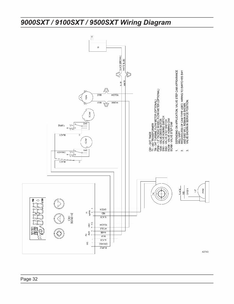
CB1 - SXT TIMERT1 - 24VAC TRANSFORMERK1 - 24VAC VALVE DRIVE RELAYPWM - 1.0" OR 1.5" PADDLE WHEEL FLOW METER (OPTIONAL)VDM - VALVE DRIVE MOTORSW1 - VALVE HOMING SWITCHSW2 - VALVE STEP SWITCHHCAM - VALVE HOMING CAMSCAM - VALVE STEP CAM
NOTE:DEPENDING ON APPLICATION, VALVE STEP CAM APPEARANCE 1.WILL VARY.REGARDLESS OF CAM TYPE USED, WIRING TO SWITCHES SW1 2.AND SW2 WILL REMAIN AS SHOWN.VALVE SHOWN IN SERVICE POSITION.3.
42742
Page 32
9000SXT / 9100SXT / 9500SXT Wiring Diagram
42743

Page 33
Troubleshooting
Error Codes
Note: Error codes appear on the In Service display.
Error
Code
Error Type Cause Reset and Recovery
0 Cam Sense
Error
The valve drive took longer
than 6 minutes to advance to
the next regeneration position.
Unplug the unit and examine the powerhead. Verify
that all cam switches are connected to the circuit
board and functioning properly. Verify that the motor
and drive train components are in good condition
and assembled properly. Check the valve and verify
that the piston travels free.y. Replace/reassemble
the various components as necessary.
Plug the unit back in and observe its behavior. The
unit should cycle to the next valve position and stop.
If the error re-occurs, unplug the unit and contact
technical support.
1 Cycle Step
Error
The control experienced an
unexpected cycle input
Unplug the unit and examine the powerhead.
Verify that all cam switches are connected to the
circuit board and functioning properly. Enter Master
Programming mode and verify that the valve type
and system type are set correctly with regard to the
unit itself.
Step the unit through a manual regeneration and
verify that it functions correctly. If the error re-occurs
unplug the unit and contact technical support.
2 Regen
Failure
The system has not
regenerated for more than 99
days (or 7 days if the Control
Type has been set to Day-of-
Week).
Perform a Manual Regeneration to reset the
error code. If the system is metered, verify that it
is measuring flow by running service water and
watching for the flow indicator on the display. If the
unit does not measure flow, verify that the meter
cable is connected properly and that the meter is
functioning properly.
Enter Master Programming mode and verify that the
unit is configured properly. As appropriate for the
valve configuration, check that the corrct system
capacity has been selected, that the day override is
set properly, and that the meter is identified correctly.
If the unit is configured as a Day-of-Week system,
verify that at least one days is set ON. Correct the
settings as necessary.
3 Memory
Error
Control board memory failure. Perform a Master Reset and reconfigure the system
via Master Programming mode. After reconfiguring
the system, set the valve through a manual
regeneration. If the rror re-occirs, unplug the unit and
contact technical support.
2 There
have been
more than
99 days
since
the last
Regeneration must occur for the unit to
recover, the display to clear and the valve
to function normally.
[ 7 - - 5 ]: To recover from [Err2], the user
must initiate a regeneration or set at least
one individual day to 1.
Page 34
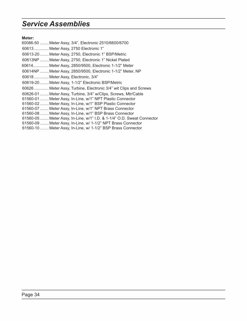
Service Assemblies
Meter:
60086-50 ........Meter Assy, 3/4”, Electronic 2510/6600/6700
60613 .............Meter Assy, 2750 Electronic 1”
60613-20 ........Meter Assy, 2750, Electronic 1” BSP/Metric
60613NP ........Meter Assy, 2750, Electronic 1” Nickel Plated
60614..............Meter Assy, 2850/9500, Electronic 1-1/2” Meter
60614NP ........Meter Assy, 2850/9500, Electronic 1-1/2” Meter, NP
60618 .............Meter Assy, Electronic, 3/4”
60619-20 ........Meter Assy, 1-1/2” Electronic BSP/Metric
60626 .............Meter Assy, Turbine, Electronic 3/4” wit Clips and Screws
60626-01 ........Meter Assy, Turbine, 3/4” w/Clips, Screws, Mtr/Cable
61560-01 ........Meter Assy, In-Line, w/1” NPT Plastic Connector
61560-02 ........Meter Assy, In-Line, w/1” BSP Plastic Connector
61560-07 ........Meter Assy, In-Line, w/1” NPT Brass Connector
61560-08 ........Meter Assy, In-Line, w/1” BSP Brass Connector
61560-05 ........Meter Assy, In-Line, w/1” I.D. & 1-1/4” O.D. Sweat Connector
61560-09 ........Meter Assy, In-Line, w/ 1-1/2” NPT Brass Connector
61560-10 ........Meter Assy, In-Line, w/ 1-1/2” BSP Brass Connector

P/N 42713 Rev. D 2/27/09
Model 2510 & 2510 Econominder
Service Manual
IMPORTANT: Fill in Pertinent Information on Page 3 for Future Reference
Job Specification Sheet ......................................................................................................................................... 3
Installation Instructions .......................................................................................................................................... 4
Start-Up Instructions .............................................................................................................................................. 5
3200 Timer Setting Procedure ............................................................................................................................... 6
3210 Timer Settings............................................................................................................................................... 7
3200 & 3210 Timer Series ..................................................................................................................................... 8
3200 Timer Assembly .......................................................................................................................................... 10
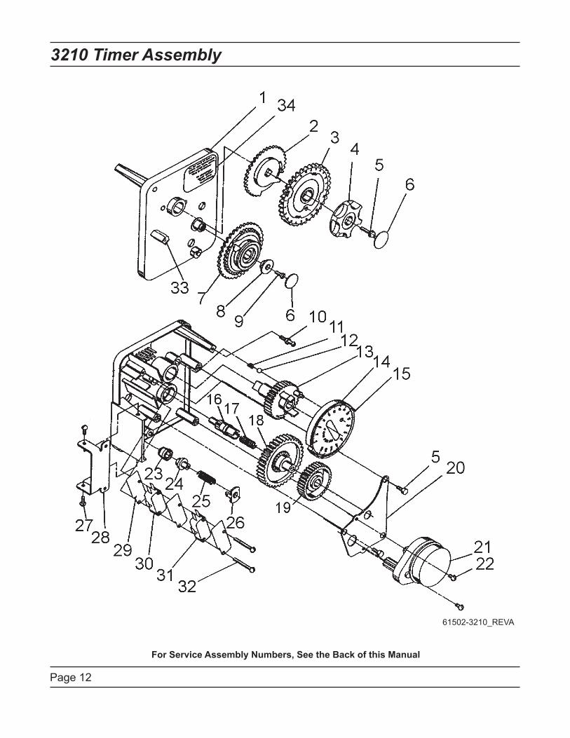
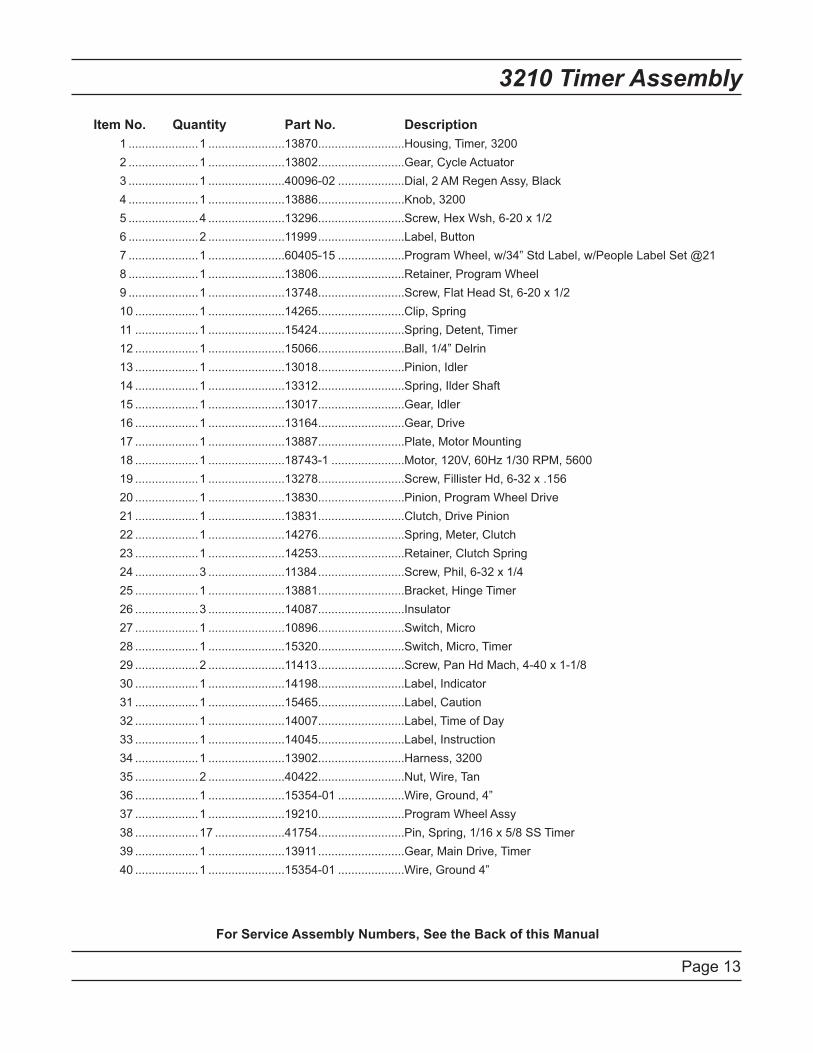
3210 Timer Assembly .......................................................................................................................................... 12
Powerhead Assembly .......................................................................................................................................... 14
Powerhead Assembly (Environmental)................................................................................................................ 16
Manual Powerhead Assembly ............................................................................................................................. 18
Control Valve Assembly ....................................................................................................................................... 20
Softener & Filter Conversion Kits ........................................................................................................................ 22
Meter Assembly ................................................................................................................................................... 23
1600 Brine System Assembly .............................................................................................................................. 24
1650 Brine System Assembly .............................................................................................................................. 25
Bypass Valve Assembly (Plastic) ......................................................................................................................... 26
Bypass Valve Assembly (Metal) .......................................................................................................................... 27
2300 Safety Brine Valve ...................................................................................................................................... 28
2310 Safety Brine Valve ...................................................................................................................................... 29
Service Instructions ............................................................................................................................................. 30
Seal & Spacer Replacement ............................................................................................................................... 31
Troubleshooting ................................................................................................................................................... 33
Flow Data & Injector Draw Rates ........................................................................................................................ 35
Wiring Diagram .................................................................................................................................................... 36
Service Assemblies ............................................................................................................................................. 37
Table of Contents
IMPORTANT PLEASE READ:
The information, specifications and illustrations in this manual are based on the latest information available at the time of •
printing. The manufacturer reserves the right to make changes at any time without notice.
This manual is intended as a guide for service of the valve only. System installation requires information from a number of •
suppliers not known at the time of manufacture. This product should be installed by a plumbing professional.
This unit is designed to be installed on potable water systems only.•
This product must be installed in compliance with all state and municipal plumbing and electrical codes. Permits may be •
required at the time of installation.
If daytime operating pressure exceeds 80 psi (5.5 bar), nighttime pressures may exceed pressure limits. A pressure reducing •
valve must be installed.
Do not install the unit where temperatures may drop below 32°F (0°C) or above 110°F (43°C). •
Do not place the unit in direct sunlight. Black units will absorb radiant heat increasing internal temperatures. •
Do not strike the valve or any of the components.•
Warranty of this product extends to manufacturing defects. Misapplication of this product may result in failure to properly •
condition water, or damage to product.
A prefilter should be used on installations in which free solids are present. •
In some applications local municipalities treat water with Chloramines. High Chloramine levels may damage valve components.•
Correct and constant voltage must be supplied to the control valve to maintain proper function.•

Job Number: __________________
Model Number: ________________
Water Hardness: ___________________ ppm or gpg
Capacity Per Unit: ______________
Mineral Tank Size: ___________ Diameter: ___________ Height:
Salt Setting per Regeneration: _____________________________________________
1. Type of Timer:
A. 7 Day or 12 Day B. Meter Initiated
2. Downflow: Upflow Upflow Variable
3. Meter Size:
A. 3/4” Std Range (125 - 2,100 gallon setting)
B. 3/4” Ext Range (625 - 10,625 gallon setting)
C. 1” Std Range (310 - 5,270 gallon setting)
D. 1” Ext Range (1,150 - 26,350 gallon setting)
E. 1-1/2” Std Range (625 - 10,625 gallon setting)
F. 1-1/2” Ext Range (3,125 - 53,125 gallon setting)
G. 2” Std Range (1,250 - 21,250 gallon setting)
H. 2” Ext Range (6,250 - 106,250 gallon setting)
I. 3” Std Range (3,750 - 63,750 gallon setting)
J. 3” Ext Range (18,750 - 318,750 gallon setting)
K. Electronic________ Pulse Count ________ Meter Size
4. System Type:
A. System #4: 1 Tank, 1 Meter, Immediate, or Delayed Regeneration
B. System #4: Time Clock
C. System #4: Twin Tank
D. System #5: 2-5 Tanks, 2 Meters, Interlock
E. System #6: 2-5 Tanks, 1 Meter, Series Regeneration
F. System #7: 2-5 Tanks, 1 Meter, Alternating
G. System #9: Electronic Only, 2-4 Tanks, Meter per Valve, Alternating
H. System #14: Electronic Only, 2-4 Tanks, Meter per Valve. Brings units on and offline based on flow.
5. Timer Program Settings:
A. Backwash: ______________________ Minutes
B. Brine and Slow Rinse: _____________ Minutes
C. Rapid Rinse: ____________________ Minutes
D. Brine Tank Refill: _________________ Minutes
E. Pause Time: ____________________ Minutes
F. Second Backwash: _______________ Minutes
6. Drain Line Flow Control: ____________ gpm
7. Brine Line Flow Controller: __________________ gpm
8. Injector Size#: _____________________
9. Piston Type:
A. Hard Water Bypass
B. No Hard Water Bypass
Job Specification Sheet
Page 4
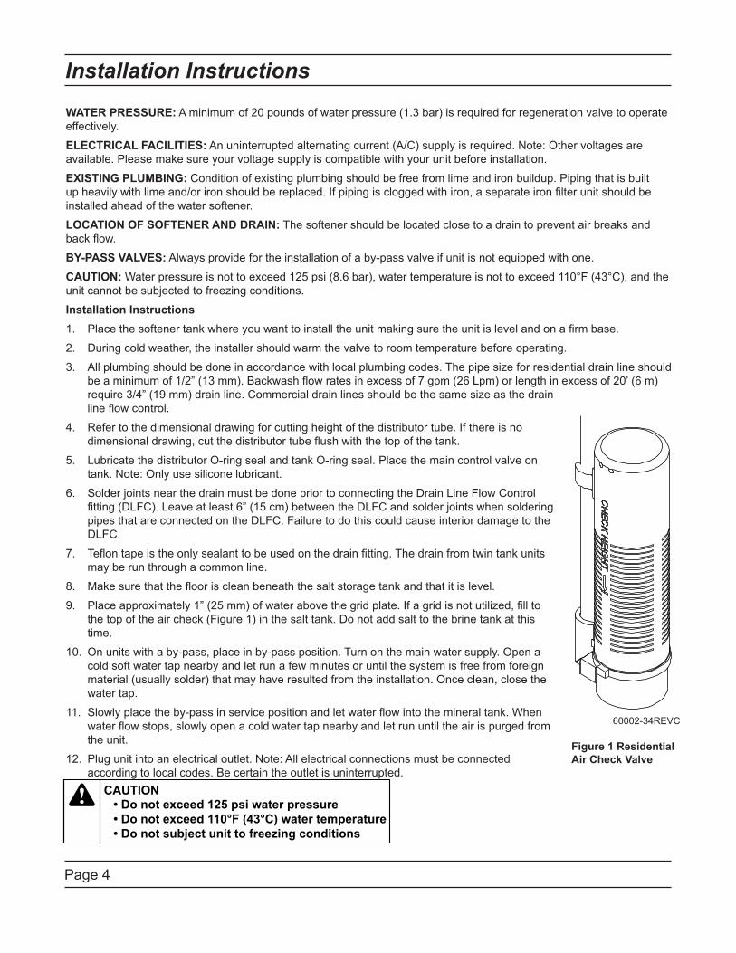
Installation Instructions
WATER PRESSURE: A minimum of 20 pounds of water pressure (1.3 bar) is required for regeneration valve to operate
effectively.
ELECTRICAL FACILITIES: An uninterrupted alternating current (A/C) supply is required. Note: Other voltages are
available. Please make sure your voltage supply is compatible with your unit before installation.
EXISTING PLUMBING: Condition of existing plumbing should be free from lime and iron buildup. Piping that is built
up heavily with lime and/or iron should be replaced. If piping is clogged with iron, a separate iron filter unit should be
installed ahead of the water softener.
LOCATION OF SOFTENER AND DRAIN: The softener should be located close to a drain to prevent air breaks and
back flow.
BY-PASS VALVES: Always provide for the installation of a by-pass valve if unit is not equipped with one.
CAUTION: Water pressure is not to exceed 125 psi (8.6 bar), water temperature is not to exceed 110°F (43°C), and the
unit cannot be subjected to freezing conditions.
Installation Instructions
Place the softener tank where you want to install the unit making sure the unit is level and on a firm base.1.
During cold weather, the installer should warm the valve to room temperature before operating.2.
All plumbing should be done in accordance with local plumbing codes. The pipe size for residential drain line should 3.
be a minimum of 1/2” (13 mm). Backwash flow rates in excess of 7 gpm (26 Lpm) or length in excess of 20’ (6 m)
require 3/4” (19 mm) drain line. Commercial drain lines should be the same size as the drain
line flow control.
Refer to the dimensional drawing for cutting height of the distributor tube. If there is no 4.
dimensional drawing, cut the distributor tube flush with the top of the tank.
Lubricate the distributor O-ring seal and tank O-ring seal. Place the main control valve on 5.
tank. Note: Only use silicone lubricant.
Solder joints near the drain must be done prior to connecting the Drain Line Flow Control 6.
fitting (DLFC). Leave at least 6” (15 cm) between the DLFC and solder joints when soldering
pipes that are connected on the DLFC. Failure to do this could cause interior damage to the
DLFC.
Teflon tape is the only sealant to be used on the drain fitting. The drain from twin tank units 7.
may be run through a common line.
Make sure that the floor is clean beneath the salt storage tank and that it is level.8.
Place approximately 1” (25 mm) of water above the grid plate. If a grid is not utilized, fill to 9.
the top of the air check (Figure 1) in the salt tank. Do not add salt to the brine tank at this
time.
On units with a by-pass, place in by-pass position. Turn on the main water supply. Open a 10.
cold soft water tap nearby and let run a few minutes or until the system is free from foreign
material (usually solder) that may have resulted from the installation. Once clean, close the
water tap.
Slowly place the by-pass in service position and let water flow into the mineral tank. When 11.
water flow stops, slowly open a cold water tap nearby and let run until the air is purged from
the unit.
Plug unit into an electrical outlet. Note: All electrical connections must be connected 12.
according to local codes. Be certain the outlet is uninterrupted.
60002-34REVC
Figure 1 Residential
Air Check Valve
Page 5
Start-Up Instructions
The water softener should be installed with the inlet, outlet, and drain connections made in accordance with the
manufacturer’s recommendations, and to meet applicable plumbing codes.
Turn the manual regeneraton knob slowly in a clockwise direction until the program micro switch lifts on top of 1.
the first set of pins. Allow the drive motor to move the piston to the first regeneration step and stop. Each time
the program switch position changes, the valve will advance to the next regeneration step. Always allow the
motor to stop before moving to the next set of pins or spaces.
NOTE: For electronic valves, please refer to the manual regeneration part of the timer operation
section. If the valve came with a separate electronic timer service manual, refer to the timer operation
section of the electronic timer service manual.
Position the valve to backwash. Ensure the drain line flow remains steady for 10 minutes or until the water 2.
runs clear (see above).
Position the valve to the brine / slow rinse position. Ensure the unit is drawing water from the brine tank (this 3.
step may need to be repeated).
Position the valve to the rapid rinse position. Check the drain line flow, and run for 5 minutes or until the water 4.
runs clear.
Position the valve to the start of the brine tank fill cycle. Ensure water goes into the brine tank at the desired 5.
rate. The brine valve drive cam will hold the valve in this position to fill the brine tank for the first regeneration.
Replace control box cover.6.
Put salt in the brine tank. 7.
NOTE: Do not use granulated or rock salt.
Page 6
3200 Timer Setting Procedure
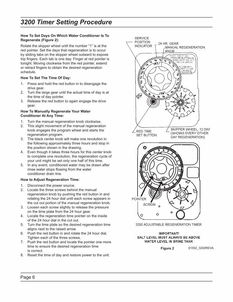
How To Set Days On Which Water Conditioner Is To
Regenerate (Figure 2):
Rotate the skipper wheel until the number “1” is at the
red pointer. Set the days that regeneration is to occur
by sliding tabs on the skipper wheel outward to expose
trip fingers. Each tab is one day. Finger at red pointer is
tonight. Moving clockwise from the red pointer, extend
or retract fingers to obtain the desired regeneration
schedule.
How To Set The Time Of Day:
1. Press and hold the red button in to disengage the
drive gear.
2. Turn the large gear until the actual time of day is at
the time of day pointer.
3. Release the red button to again engage the drive
gear.
How To Manually Regenerate Your Water
Conditioner At Any Time:
1. Turn the manual regeneration knob clockwise.
2. This slight movement of the manual regeneration
knob engages the program wheel and starts the
regeneration program.
3. The black center knob will make one revolution in
the following approximately three hours and stop in
the position shown in the drawing.
4. Even though it takes three hours for this center knob
to complete one revolution, the regeneration cycle of
your unit might be set only one half of this time.
5. In any event, conditioned water may be drawn after
rinse water stops flowing from the water
conditioner drain line.
How to Adjust Regeneration Time:
1. Disconnect the power source.
2. Locate the three screws behind the manual
regeneration knob by pushing the red button in and
rotating the 24 hour dial until each screw appears in
the cut out portion of the manual regeneration knob.
3. Loosen each screw slightly to release the pressure
on the time plate from the 24 hour gear.
4. Locate the regeneration time pointer on the inside
of the 24 hour dial in the cut out.
5. Turn the time plate so the desired regeneration time
aligns next to the raised arrow.
6. Push the red button in and rotate the 24 hour dial.
Tighten each of the three screws.
7. Push the red button and locate the pointer one more
time to ensure the desired regeneration time
is correct.
8. Reset the time of day and restore power to the unit.
Figure 2 61502_3200REVA

Page 7
3210 Timer Settings
Page 7
Typical Programming Procedure
Calculate the gallon capacity of the system, subtract
the necessary reserve requirement and set the gallons
available opposite the small white dot on the program
wheel gear.
NOTE: Drawing shows 8,750 gallon setting. The
capacity (gallons) arrow (15)shows zero gallons
remaining. The unit will regenerate tonight at the set
regeneration time.
How To Set The Time Of Day:
Press and hold the red button in to disengage the 1.
drive gear.
Turn the large gear until the actual time of day is 2.
opposite the time of day pointer.
Release the red button to again engage the drive 3.
gear.
How To Manually Regenerate Your Water
Conditioner At Any Time:
Turn the manual regeneration knob clockwise.1.
This slight movement of the manual regeneration 2.
knob engages the program wheel and starts the
regeneration program.
The black center knob will make one revolution in the
following approximately three hours and stop in the
position shown in the drawing.
Even though it takes three hours for this center 3.
knob to complete one revolution, the regeneration
cycle of your unit might be set for only one half of
this time.
In any event, conditioned water may be drawn after 4.
rinse water stops flowing from the water conditioner
drain line.
Immediate Regeneration Timers:
These timers do not have a 24 hour gear. Setting the
gallons on the program wheel and manual regeneration
procedure are the same as previous instructions. The
timer will regenerate as soon as the capacity gallons
reaches zero.
NOTE:
The program wheel to the
left may be different than the
program wheel on the product.
NOTE:
To set meter capacity rotate
manual knob one - 360°
revolution to set gallonage.
Figure 361502_3200REVA

Page 8
3200 & 3210 Timer Series
How To Set The Regeneration Cycle Program:
The regeneration cycle program on your water
conditioner has been factory preset, however,
portions of the cycle or program may be lengthened or
shortened in time to suit local conditions.
3200 & 3210 Series Timers (Figure 4)
To expose cycle program wheel, grasp timer in 1.
upper left-hand corner and pull, releasing snap
retainer and swinging timer to the right.
To change the regeneration cycle program, the 2.
program wheel must be removed. Grasp program
wheel and squeeze protruding lugs toward center,
lift program wheel off timer. Switch arms may
require movement to facilitate removal.
Return timer to closed position engaging snap 3.
retainer in back plate. Make certain all electrical
wires locate above snap retainer post.
Timer Setting Procedure for 3200 & 3210
Timer
How To Change The Length Of The Backwash
Time:
The program wheel as shown in the drawing is in the
service position. As you look at the numbered side of
the program wheel, the group of pins starting at zero
determines the length of time your unit will backwash.
EXAMPLE: If there are six pins in this section, the time
of backwash will be 12 min. (2 min. per pin). To change
the length of backwash time, add or remove pins as
required. The number of pins times two equals the
backwash time in minutes.
How To Change The Length Of Brine And Rinse
Time:
The group of holes between the last pin in the 1.
backwash section and the second group of pins
determines the length of time that your unit will
brine and rinse (2 min. per hole).
To change the length of brine and rinse time, move 2.
the rapid rinse group of pins to give more or fewer
holes in the brine and rinse section. Number of
holes times two equals brine and rinse time in
minutes.
How To Change The Length Of Rapid Rinse:
The second group of pins on the program wheel 1.
determines the length of time that your water
conditioner will rapid rinse (2 min. per pin).
To change the length of rapid rinse time, add or 2.
remove pins at the higher numbered end of this
section as required. The number of pins times two
equals the rapid rinse time in minutes.
How To Change The Length Of Brine Tank Refill
Time:
The second group of holes in the program wheel 1.
determines the length of time that your water
conditioner will refill the brine tank (2 min. per hole).
To change the length of refill time, move the two 2.
pins at the end of the second group of holes as
required.
The regeneration cycle is complete when the outer 3.
microswitch is tripped by the two pin set at end of
the brine tank refill section.
The program wheel, however, will continue to rotate 4.
until the inner micro-switch drops into the notch on
the program wheel.
Regeneration Cycle Program Setting Procedure
(Downflow)
Figure 4
61502_3210REVA

Page 9
Notes
Page 10
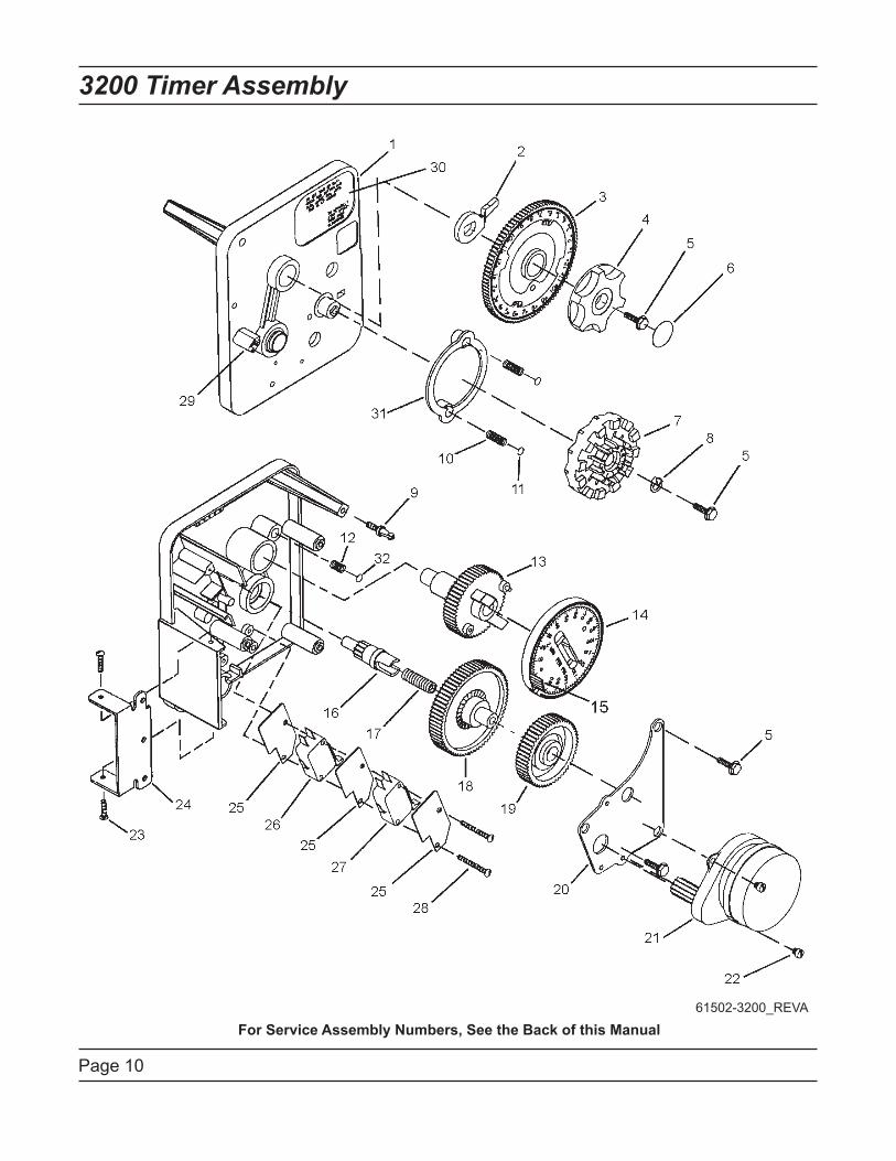
3200 Timer Assembly
For Service Assembly Numbers, See the Back of this Manual
61502-3200_REVA
Page 11
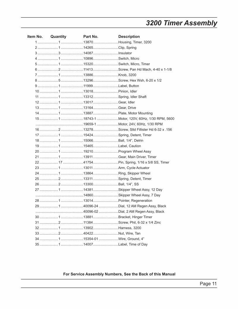
3200 Timer Assembly
Item No. Quantity Part No. Description
1 .....................1 .......................13870 ..........................Housing, Timer, 3200
2 .....................1 .......................14265 ..........................Clip, Spring
3 .....................3 .......................14087 ..........................Insulator
4 .....................1 .......................10896 ..........................Switch, Micro
5 .....................1 .......................15320 ..........................Switch, Micro, Timer
6 .....................2 .......................11413 ..........................Screw, Pan Hd Mach, 4-40 x 1-1/8
7 .....................1 .......................13886 ..........................Knob, 3200
8 .....................5 .......................13296 ..........................Screw, Hex Wsh, 6-20 x 1/2
9 .....................1 .......................11999 ..........................Label, Button
10 ...................1 .......................13018 ..........................Pinion, Idler
11 ...................1 .......................13312 ..........................Spring, Idler Shaft
12 ...................1 .......................13017 ..........................Gear, Idler
13 ...................1 .......................13164 ..........................Gear, Drive
14 ...................1 .......................13887 ..........................Plate, Motor Mounting
15 ...................1 .......................18743-1 ......................Motor, 120V, 60Hz, 1/30 RPM, 5600
.................................................19659-1 ......................Motor, 24V, 60Hz, 1/30 RPM
16 ...................2 .......................13278 ..........................Screw, Sltd Fillister Hd 6-32 x .156
17 ...................1 .......................15424 ..........................Spring, Detent, Timer
18 ...................1 .......................15066 ..........................Ball, 1/4”, Delrin
19 ...................1 .......................15465 ..........................Label, Caution
20 ...................1 .......................19210 ..........................Program Wheel Assy
21 ...................1 .......................13911 ..........................Gear, Main Driver, Timer
22 ...................17 .....................41754 ..........................Pin, Spring, 1/16 x 5/8 SS, Timer
23 ...................1 .......................13011 ..........................Arm, Cycle Actuator
24 ...................1 .......................13864 ..........................Ring, Skipper Wheel
25 ...................2 .......................13311 ..........................Spring, Detent, Timer
26 ...................2 .......................13300 ..........................Ball, 1/4”, SS
27 ...................1 .......................14381 ..........................Skipper Wheel Assy, 12 Day
.................................................14860 ..........................Skipper Wheel Assy, 7 Day
28 ...................1 .......................13014 ..........................Pointer, Regeneration
29 ...................1 .......................40096-24 ....................Dial, 12 AM Regen Assy, Black
.................................................40096-02 ....................Dial, 2 AM Regen Assy, Black
30 ...................1 .......................13881 ..........................Bracket, Hinger Timer
31 ...................2 .......................11384 ..........................Screw, Phil, 6-32 x 1/4 Zinc
32 ...................1 .......................13902 ..........................Harness, 3200
33 ...................2 .......................40422 ..........................Nut, Wire, Tan
34 ...................1 .......................15354-01 ....................Wire, Ground, 4”
35 ...................1 .......................14007 ..........................Label, Time of Day
For Service Assembly Numbers, See the Back of this Manual
Page 12
3210 Timer Assembly
For Service Assembly Numbers, See the Back of this Manual
61502-3210_REVA
Page 13
3210 Timer Assembly
For Service Assembly Numbers, See the Back of this Manual
Item No. Quantity Part No. Description
1 .....................1 .......................13870 ..........................Housing, Timer, 3200
2 .....................1 .......................13802 ..........................Gear, Cycle Actuator
3 .....................1 .......................40096-02 ....................Dial, 2 AM Regen Assy, Black
4 .....................1 .......................13886 ..........................Knob, 3200
5 .....................4 .......................13296 ..........................Screw, Hex Wsh, 6-20 x 1/2
6 .....................2 .......................11999 ..........................Label, Button
7 .....................1 .......................60405-15 ....................Program Wheel, w/34” Std Label, w/People Label Set @21
8 .....................1 .......................13806 ..........................Retainer, Program Wheel
9 .....................1 .......................13748 ..........................Screw, Flat Head St, 6-20 x 1/2
10 ...................1 .......................14265 ..........................Clip, Spring
11 ...................1 .......................15424 ..........................Spring, Detent, Timer
12 ...................1 .......................15066 ..........................Ball, 1/4” Delrin
13 ...................1 .......................13018 ..........................Pinion, Idler
14 ...................1 .......................13312 ..........................Spring, Ilder Shaft
15 ...................1 .......................13017 ..........................Gear, Idler
16 ...................1 .......................13164 ..........................Gear, Drive
17 ...................1 .......................13887 ..........................Plate, Motor Mounting
18 ...................1 .......................18743-1 ......................Motor, 120V, 60Hz 1/30 RPM, 5600
19 ...................1 .......................13278 ..........................Screw, Fillister Hd, 6-32 x .156
20 ...................1 .......................13830 ..........................Pinion, Program Wheel Drive
21 ...................1 .......................13831 ..........................Clutch, Drive Pinion
22 ...................1 .......................14276 ..........................Spring, Meter, Clutch
23 ...................1 .......................14253 ..........................Retainer, Clutch Spring
24 ...................3 .......................11384 ..........................Screw, Phil, 6-32 x 1/4
25 ...................1 .......................13881 ..........................Bracket, Hinge Timer
26 ...................3 .......................14087 ..........................Insulator
27 ...................1 .......................10896 ..........................Switch, Micro
28 ...................1 .......................15320 ..........................Switch, Micro, Timer
29 ...................2 .......................11413 ..........................Screw, Pan Hd Mach, 4-40 x 1-1/8
30 ...................1 .......................14198 ..........................Label, Indicator
31 ...................1 .......................15465 ..........................Label, Caution
32 ...................1 .......................14007 ..........................Label, Time of Day
33 ...................1 .......................14045 ..........................Label, Instruction
34 ...................1 .......................13902 ..........................Harness, 3200
35 ...................2 .......................40422 ..........................Nut, Wire, Tan
36 ...................1 .......................15354-01 ....................Wire, Ground, 4”
37 ...................1 .......................19210 ..........................Program Wheel Assy
38 ...................17 .....................41754 ..........................Pin, Spring, 1/16 x 5/8 SS Timer
39 ...................1 .......................13911 ..........................Gear, Main Drive, Timer
40 ...................1 .......................15354-01 ....................Wire, Ground 4”
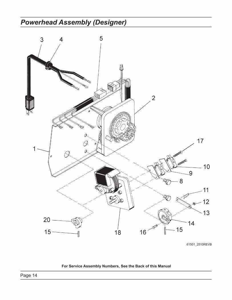
Page 14
Powerhead Assembly (Designer)
For Service Assembly Numbers, See the Back of this Manual
61501_2510REVB

Page 15
Powerhead Assembly (Designer)
For Service Assembly Numbers, See the Back of this Manual
Item No. Quantity Part No. Description
1 .....................1 .......................40264 ..........................Backplate, SS/SVO, W-T-Screws
2 .....................1 ...........................................................3200, Timer 7 or 12 Day
3 .....................1 .......................11838 ..........................Power Cord
4 .....................1 .......................13547 ..........................Strain Relief
5 .....................1 .......................40400 ..........................Harness, Drive, Designer/Environmental
8 .....................2 .......................10231 ..........................Screw, Drive Mounting
9 .....................2 .......................10302 ..........................Insulator
10 ...................2 .......................10218 ..........................Switch
11 ...................1 .......................10909 ..........................Connecting Link Pin
12 ...................1 .......................10250 ..........................Retaining Ring
13 ...................1 .......................10621 ..........................Connecting Link
14 ...................1 .......................12576 ..........................Drive Cam, STF (Black)
.......................1 .......................12102 ..........................Drive Cam, RR (White)
15 ...................2 .......................10338 ..........................Roll Pin
16 ...................1 .......................13366 ..........................Drive Bearing
17 ...................2 .......................14923 ..........................Screw, Switch Mounting
18 ...................1 .......................41543* ........................Motor, Drive, 115V, 50/60Hz
.................................................42579** .......................Motor, Drive, 24VAC/VDC, 50/60Hz
.................................................41545* ........................Motor, Drive, 230V, 50/60Hz
20 ...................1 .......................12777 ..........................Brine Valve Cam, STF (Black)
.......................1 .......................10815 ..........................Brine Valve Cam, RR (White)
Not Shown:
.......................2 .......................10300 ..........................Screw, Timer Mounting
.......................1 .......................13741 ..........................Hole Plug
.......................1 .......................17904 ..........................Hole Plug
.......................2 .......................19367 ..........................Screw, Thumb
.......................1 .......................15441 ..........................Meter Cable Guide Assy (Econominder Only)
.......................1 .......................15495 ..........................Meter Cable,13.87” (Econominder Only)
.......................1 .......................60232-110 ...................Cover, Designer, 1 Pc, Black
* Bracket is integrated into the motor.
** Bracket is integrated into motor. Picture may not reflect component.
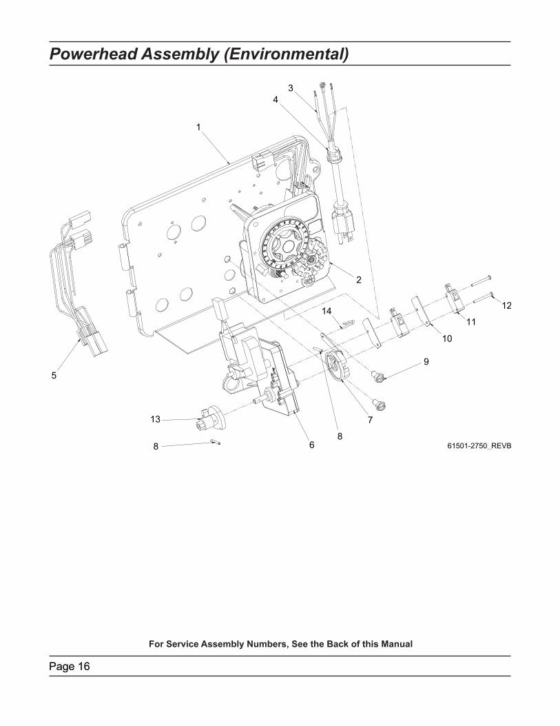
Page 16
For Service Assembly Numbers, See the Back of this Manual
Powerhead Assembly (Environmental)
Page 16
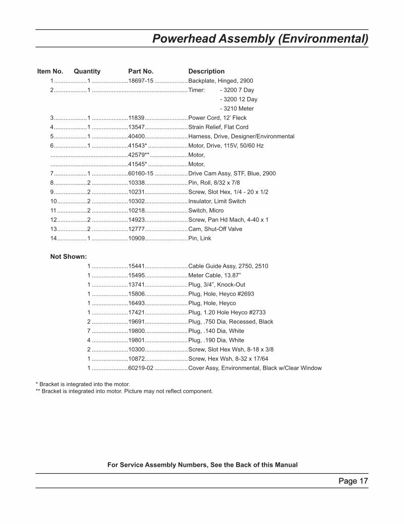
Page 17
For Service Assembly Numbers, See the Back of this Manual
Powerhead Assembly (Environmental)
Page 17
Item No. Quantity Part No. Description
1 ....................1 ......................18697-15 ....................Backplate, Hinged, 2900
2 ....................1 ..........................................................Timer: - 3200 7 Day
- 3200 12 Day
- 3210 Meter
3 ....................1 ......................11839 ..........................Power Cord, 12’ Fleck
4 ....................1 ......................13547 ..........................Strain Relief, Flat Cord
5 ....................1 ......................40400 ..........................Harness, Drive, Designer/Environmental
6 ....................1 ......................41543* ........................Motor, Drive, 115V, 50/60 Hz
...............................................42579** .......................Motor,
...............................................41545* ........................Motor,
7 ....................1 ......................60160-15 ....................Drive Cam Assy, STF, Blue, 2900
8 ....................2 ......................10338 ..........................Pin, Roll, 8/32 x 7/8
9 ....................2 ......................10231 ..........................Screw, Slot Hex, 1/4 - 20 x 1/2
10 ..................2 ......................10302 .......................... Insulator, Limit Switch
11 ..................2 ......................10218 ..........................Switch, Micro
12 ..................2 ......................14923 ..........................Screw, Pan Hd Mach, 4-40 x 1
13 ..................2 ......................12777 ..........................Cam, Shut-Off Valve
14 ..................1 ......................10909 ..........................Pin, Link
Not Shown:
1 ......................15441 ..........................Cable Guide Assy, 2750, 2510
1 ......................15495 ..........................Meter Cable, 13.87”
1 ......................13741 ..........................Plug, 3/4”, Knock-Out
1 ......................15806 ..........................Plug, Hole, Heyco #2693
1 ......................16493 ..........................Plug, Hole, Heyco
1 ......................17421 ..........................Plug, 1.20 Hole Heyco #2733
2 ......................19691 ..........................Plug, .750 Dia, Recessed, Black
7 ......................19800 ..........................Plug, .140 Dia, White
4 ......................19801 ..........................Plug, .190 Dia, White
2 ......................10300 ..........................Screw, Slot Hex Wsh, 8-18 x 3/8
1 ......................10872 ..........................Screw, Hex Wsh, 8-32 x 17/64
1 ......................60219-02 ....................Cover Assy, Environmental, Black w/Clear Window
* Bracket is integrated into the motor.
** Bracket is integrated into motor. Picture may not reflect component.
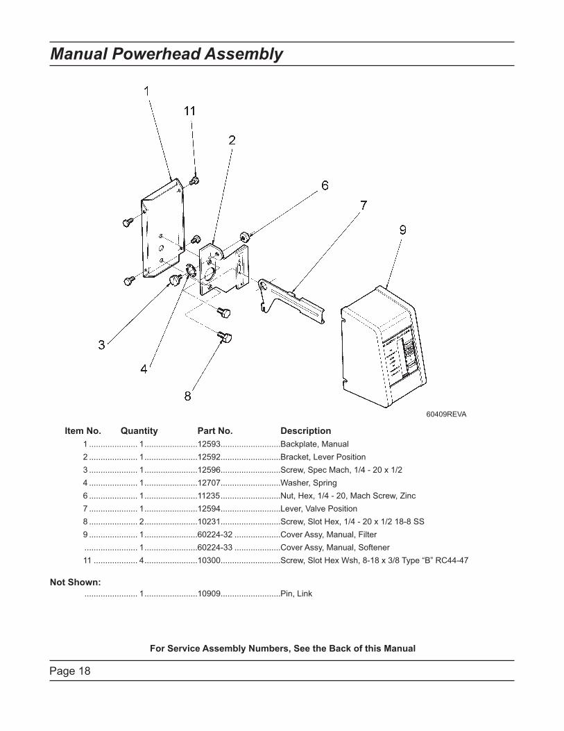
Page 18
Manual Powerhead Assembly
Item No. Quantity Part No. Description
1 ..................... 1 .......................12593 ..........................Backplate, Manual
2 ..................... 1 .......................12592 ..........................Bracket, Lever Position
3 ..................... 1 .......................12596 ..........................Screw, Spec Mach, 1/4 - 20 x 1/2
4 ..................... 1 .......................12707 ..........................Washer, Spring
6 ..................... 1 .......................11235 ..........................Nut, Hex, 1/4 - 20, Mach Screw, Zinc
7 ..................... 1 .......................12594 ..........................Lever, Valve Position
8 ..................... 2 .......................10231 ..........................Screw, Slot Hex, 1/4 - 20 x 1/2 18-8 SS
9 ..................... 1 .......................60224-32 ....................Cover Assy, Manual, Filter
....................... 1 .......................60224-33 ....................Cover Assy, Manual, Softener
11 ................... 4 .......................10300 ..........................Screw, Slot Hex Wsh, 8-18 x 3/8 Type “B” RC44-47
Not Shown:
....................... 1 .......................10909 ..........................Pin, Link
For Service Assembly Numbers, See the Back of this Manual
60409REVA

Page 19
Notes
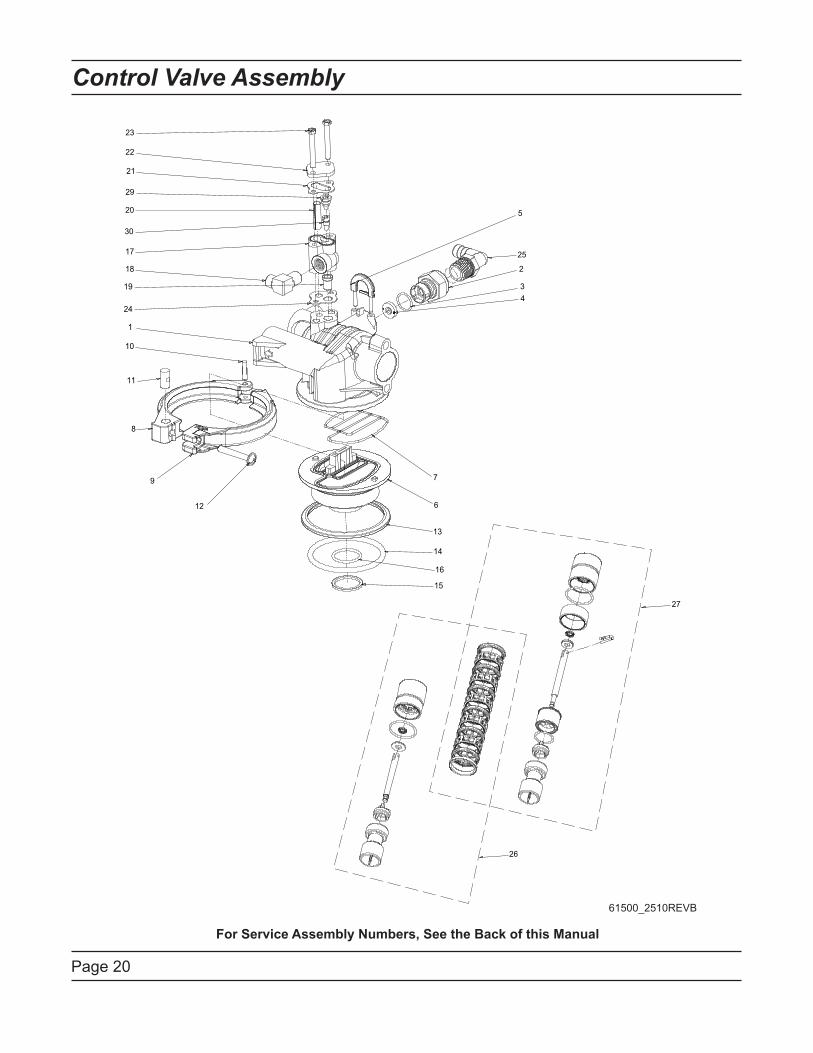
Page 20
Control Valve Assembly
For Service Assembly Numbers, See the Back of this Manual
22
23
25
2
15
6
13
9
12
8
11
1
24
5
18
19
17
30
20
29
21
10
4
3
14
16
7
26
27
61500_2510REVB
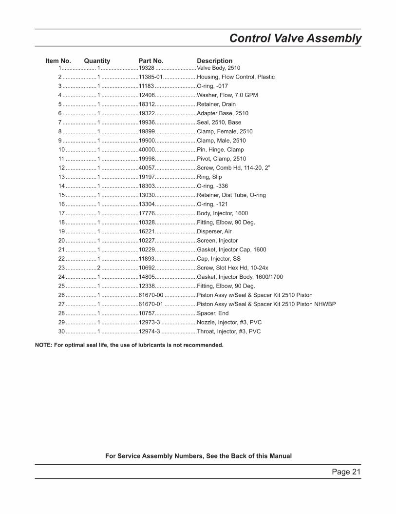
Page 21
Control Valve Assembly
For Service Assembly Numbers, See the Back of this Manual
Item No. Quantity Part No. Description 1 ...................... 1 ........................19328 ..........................Valve Body, 2510
2 .....................1 .......................11385-01 .....................Housing, Flow Control, Plastic
3 .....................1 .......................11183 ..........................O-ring, -017
4 .....................1 .......................12408 ..........................Washer, Flow, 7.0 GPM
5 .....................1 .......................18312 ..........................Retainer, Drain
6 .....................1 .......................19322 ..........................Adapter Base, 2510
7 .....................1 .......................19936 ..........................Seal, 2510, Base
8 .....................1 .......................19899 ..........................Clamp, Female, 2510
9 .....................1 .......................19900 ..........................Clamp, Male, 2510
10 ...................1 .......................40000 ..........................Pin, Hinge, Clamp
11 ...................1 .......................19998 ..........................Pivot, Clamp, 2510
12 ...................1 .......................40057 ..........................Screw, Comb Hd, 114-20, 2”
13 ...................1 .......................19197 ..........................Ring, Slip
14 ...................1 .......................18303 ..........................O-ring, -336
15 ...................1 .......................13030 ..........................Retainer, Dist Tube, O-ring
16 ...................1 .......................13304 ..........................O-ring, -121
17 ...................1 .......................17776 ..........................Body, Injector, 1600
18 ...................1 .......................10328 ..........................Fitting, Elbow, 90 Deg.
19 ...................1 .......................16221 ..........................Disperser, Air
20 ...................1 .......................10227 ..........................Screen, Injector
21 ...................1 .......................10229 ..........................Gasket, Injector Cap, 1600
22 ...................1 .......................11893 ..........................Cap, Injector, SS
23 ...................2 .......................10692 ..........................Screw, Slot Hex Hd, 10-24x
24 ...................1 .......................14805 ..........................Gasket, Injector Body, 1600/1700
25 ...................1 .......................12338 ..........................Fitting, Elbow, 90 Deg.
26 ...................1 .......................61670-00 ....................Piston Assy w/Seal & Spacer Kit 2510 Piston
27 ...................1 .......................61670-01 ....................Piston Assy w/Seal & Spacer Kit 2510 Piston NHWBP
28 ...................1 .......................10757 ..........................Spacer, End
29 ...................1 .......................12973-3 ......................Nozzle, Injector, #3, PVC
30 ...................1 .......................12974-3 ......................Throat, Injector, #3, PVC
NOTE: For optimal seal life, the use of lubricants is not recommended.
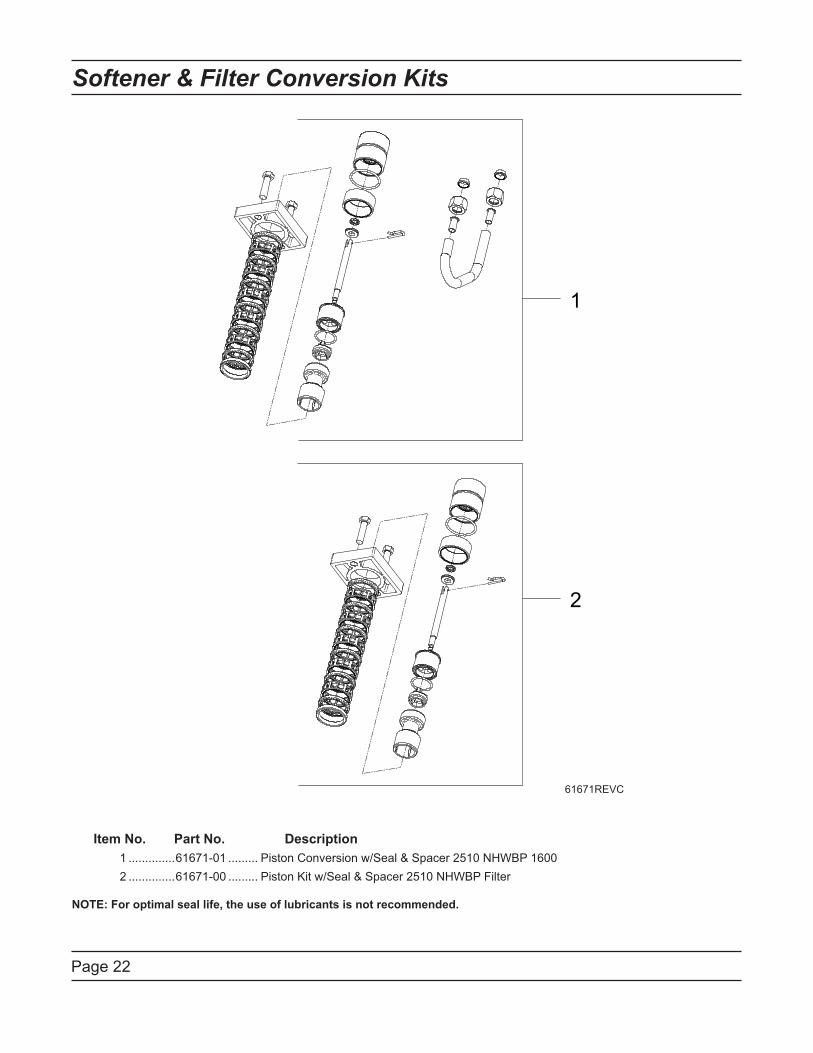
Page 22
1
2
Softener & Filter Conversion Kits
Item No. Part No. Description
1 ..............61671-01 ......... Piston Conversion w/Seal & Spacer 2510 NHWBP 1600
2 ..............61671-00 ......... Piston Kit w/Seal & Spacer 2510 NHWBP Filter
NOTE: For optimal seal life, the use of lubricants is not recommended.
61671REVC
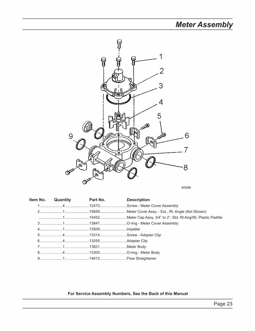
Page 23
Meter Assembly
For Service Assembly Numbers, See the Back of this Manual
Item No. Quantity Part No. Description
1 .....................4 .......................12473 ..........................Screw - Meter Cover Assembly
2 .....................1 .......................15659 ..........................Meter Cover Assy. - Ext., Rt. Angle (Not Shown)
.......................1 .......................15452 ..........................Meter Cap Assy, 3/4” to 2”, Std, Rt Ang/90, Plastic Paddle
3 .....................1 .......................13847 ..........................O-ring - Meter Cover Assembly
4 .....................1 .......................13509 ..........................Impeller
5 .....................4 .......................13314 ..........................Screw - Adapter Clip
6 .....................4 .......................13255 ..........................Adapter Clip
7 .....................1 .......................13821 ..........................Meter Body
8 .....................4 .......................13305 ..........................O-ring - Meter Body
9 .....................1 .......................14613 ..........................Flow Straightener
60088
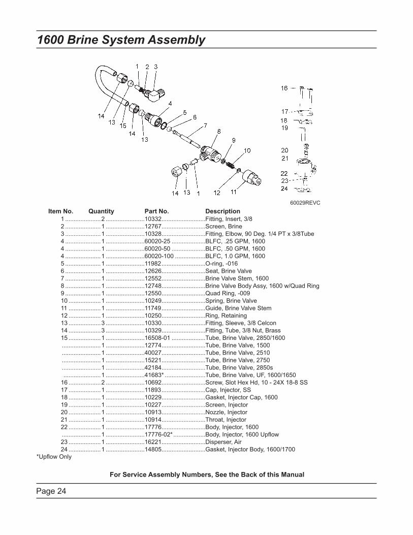
Page 24
1600 Brine System Assembly
Item No. Quantity Part No. Description
1 .....................2 .......................10332 ..........................Fitting, Insert, 3/8
2 .....................1 .......................12767 ..........................Screen, Brine
3 .....................1 .......................10328 ..........................Fitting, Elbow, 90 Deg. 1/4 PT x 3/8Tube
4 .....................1 .......................60020-25 ....................BLFC, .25 GPM, 1600
4 .....................1 .......................60020-50 ....................BLFC, .50 GPM, 1600
4 .....................1 .......................60020-100 ..................BLFC, 1.0 GPM, 1600
5 .....................1 .......................11982 ..........................O-ring, -016
6 .....................1 .......................12626 ..........................Seat, Brine Valve
7 .....................1 .......................12552 ..........................Brine Valve Stem, 1600
8 .....................1 .......................12748 ..........................Brine Valve Body Assy, 1600 w/Quad Ring
9 .....................1 .......................12550 ..........................Quad Ring, -009
10 ...................1 .......................10249 ..........................Spring, Brine Valve
11 ...................1 .......................11749 ..........................Guide, Brine Valve Stem
12 ...................1 .......................10250 ..........................Ring, Retaining
13 ...................3 .......................10330 ..........................Fitting, Sleeve, 3/8 Celcon
14 ...................3 .......................10329 ..........................Fitting, Tube, 3/8 Nut, Brass
15 ...................1 .......................16508-01 ....................Tube, Brine Valve, 2850/1600
.......................1 .......................12774 ..........................Tube, Brine Valve, 1500
.......................1 .......................40027 ..........................Tube, Brine Valve, 2510
.......................1 .......................15221 ..........................Tube, Brine Valve, 2750
.......................1 .......................42184 ..........................Tube, Brine Valve, 2850s
......................1 .......................41683* ........................Tube, Brine Valve, UF, 1600/1650
16 ...................2 .......................10692 ..........................Screw, Slot Hex Hd, 10 - 24X 18-8 SS
17 ...................1 .......................11893 ..........................Cap, Injector, SS
18 ...................1 .......................10229 ..........................Gasket, Injector Cap, 1600
19 ...................1 .......................10227 ..........................Screen, Injector
20 ...................1 .......................10913 ..........................Nozzle, Injector
21 ...................1 .......................10914 ..........................Throat, Injector
22 ...................1 .......................17776 ..........................Body, Injector, 1600
.......................1 .......................17776-02* ...................Body, Injector, 1600 Upflow
23 ...................1 .......................16221 ..........................Disperser, Air
24 ...................1 .......................14805 ..........................Gasket, Injector Body, 1600/1700
*Upflow Only
For Service Assembly Numbers, See the Back of this Manual
60029REVC
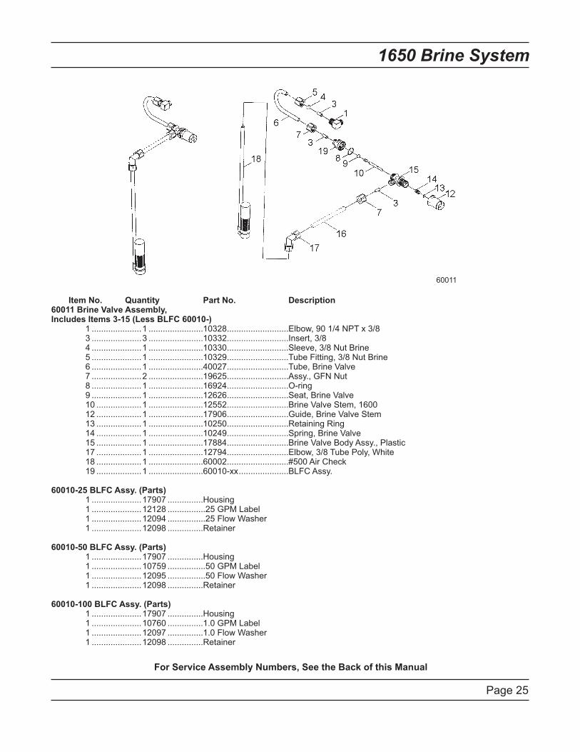
Page 25
1650 Brine System
For Service Assembly Numbers, See the Back of this Manual
Item No. Quantity Part No. Description 60011 Brine Valve Assembly, Includes Items 3-15 (Less BLFC 60010-) 1 .....................1 .......................10328 ..........................Elbow, 90 1/4 NPT x 3/8 3 .....................3 .......................10332 ..........................Insert, 3/8 4 .....................1 .......................10330 ..........................Sleeve, 3/8 Nut Brine 5 .....................1 .......................10329 ..........................Tube Fitting, 3/8 Nut Brine 6 .....................1 .......................40027 ..........................Tube, Brine Valve 7 .....................2 .......................19625 ..........................Assy., GFN Nut 8 .....................1 .......................16924 ..........................O-ring 9 .....................1 .......................12626 ..........................Seat, Brine Valve 10 ...................1 .......................12552 ..........................Brine Valve Stem, 1600 12 ...................1 .......................17906 ..........................Guide, Brine Valve Stem 13 ...................1 .......................10250 ..........................Retaining Ring 14 ...................1 .......................10249 ..........................Spring, Brine Valve 15 ...................1 .......................17884 ..........................Brine Valve Body Assy., Plastic 17 ...................1 .......................12794 ..........................Elbow, 3/8 Tube Poly, White 18 ...................1 .......................60002 ..........................#500 Air Check 19 ...................1 .......................60010-xx .....................BLFC Assy.
60010-25 BLFC Assy. (Parts) 1 .....................17907 ...............Housing 1 .....................12128 ................25 GPM Label 1 .....................12094 ................25 Flow Washer 1 .....................12098 ...............Retainer
60010-50 BLFC Assy. (Parts) 1 .....................17907 ...............Housing 1 .....................10759 ................50 GPM Label 1 .....................12095 ................50 Flow Washer 1 .....................12098 ...............Retainer
60010-100 BLFC Assy. (Parts) 1 .....................17907 ...............Housing 1 .....................10760 ...............1.0 GPM Label 1 .....................12097 ...............1.0 Flow Washer 1 .....................12098 ...............Retainer
60011

Page 26
For Service Assembly Numbers, See the Back of this Manual
Bypass Valve Assembly (Plastic)
Item No. Quantity Part No. Description
1 ....................2 ......................13305 ..........................O-ring, -119
2 ....................2 ......................13255 ..........................Clip, Mounting
3 ....................2 ......................13314 ..........................Screw, Slot Ind Hex, 8-18 x .60
4A..................1 ......................18706 ..........................Yoke, 1”, NPT, Plastic
...............................................18706-02 ....................Yoke, 3/4”, NPT, Plastic
4B .................1 ......................13708-40 ....................Yoke, 1”, Sweat
...............................................13708-45 ....................Yoke, 3/4”, Sweat
...............................................19275 ..........................Yoke, Angle 90 Deg, 3/4”, NPT
...............................................19275-45 ....................Yoke, Angle 90 Deg, 3/4” Sweat
...............................................19620-01 ....................Yoke Assy, 3/4”, R/Angle, 90 Deg w/O-rings, Clips & Screws
...............................................40636 ..........................Yoke, 1 1/4”, NPT
...............................................40636-49 ....................Yoke, 1 1/4”, Sweat
...............................................41027-01 ....................Yoke, 3/4”, NPT, Cast, Machined
...............................................41026-01 ....................Yoke, 1”, NPT, Cast, Machined, SS
60049REVD
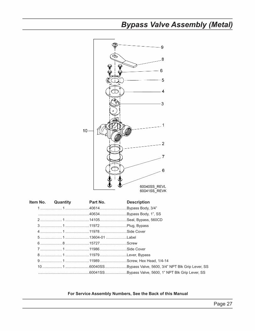
Page 27
Bypass Valve Assembly (Metal)
For Service Assembly Numbers, See the Back of this Manual
Item No. Quantity Part No. Description
1 .....................1 .......................40614 ..........................Bypass Body, 3/4”
.................................................40634 ..........................Bypass Body, 1”, SS
2 .....................1 .......................14105 ..........................Seal, Bypass, 560CD
3 .....................1 .......................11972 ..........................Plug, Bypass
4 .....................1 .......................11978 ..........................Side Cover
5 .....................1 .......................13604-01 ....................Label
6 .....................8 .......................15727 ..........................Screw
7 .....................1 .......................11986 ..........................Side Cover
8 .....................1 .......................11979 ..........................Lever, Bypass
9 .....................1 .......................11989 ..........................Screw, Hex Head, 1/4-14
10 ...................1 .......................60040SS .....................Bypass Valve, 5600, 3/4” NPT Blk Grip Lever, SS
.................................................60041SS .....................Bypass Valve, 5600, 1” NPT Blk Grip Lever, SS

Page 28
2300 Safety Brine Valve
Item No. Quantity Part No. Description
1 .....................1 .......................60027-00 ....................Safety Brine Valve, 2300, Less Elbow
2 .....................1 .......................10138 ..........................Ball, 3/8”, Brass
3 .....................1 .......................11566 ..........................Ball Stop, Slow Fill
4 .....................1 .......................10328 ..........................Fitting, Elbow, 90 Deg. 1/4 NPT x 3/8 Tube
5 .....................1 .......................10332 ..........................Fitting, Insert, 3/8
6 .....................1 .......................10330 ..........................Fitting, Sleeve, 3/8 Celcon
7 .....................1 .......................10329 ..........................Fitting, Tube, 3/8 Nut, Brass
8 .....................1 .......................10186 ..........................Nut, Hex, 10-32
9 .....................1 .......................60002-34 ....................Air Check, #500, 34” Long
.................................................60003-34 ....................Air Check, #500, HW, 34” Tube
10 ...................1 .......................10149 ..........................Rod, Float
11 ...................1 .......................10700 ..........................Float Assy, White
12 ...................3 .......................10150 ..........................Grommet, .30 Dia
For Service Assembly Numbers, See the Back of this Manual
60027REVA
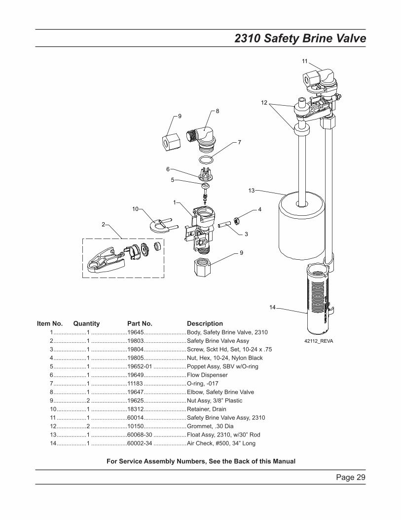
Page 29
2310 Safety Brine Valve
Item No. Quantity Part No. Description
1 ....................1 ......................19645 ..........................Body, Safety Brine Valve, 2310
2 ....................1 ......................19803 ..........................Safety Brine Valve Assy
3 ....................1 ......................19804 ..........................Screw, Sckt Hd, Set, 10-24 x .75
4 ....................1 ......................19805 ..........................Nut, Hex, 10-24, Nylon Black
5 ....................1 ......................19652-01 ....................Poppet Assy, SBV w/O-ring
6 ....................1 ......................19649 ..........................Flow Dispenser
7 ....................1 ......................11183 ..........................O-ring, -017
8 ....................1 ......................19647 ..........................Elbow, Safety Brine Valve
9 ....................2 ......................19625 ..........................Nut Assy, 3/8” Plastic
10 ..................1 ......................18312 ..........................Retainer, Drain
11 ..................1 ......................60014 ..........................Safety Brine Valve Assy, 2310
12 ..................2 ......................10150 ..........................Grommet, .30 Dia
13 ..................1 ......................60068-30 ....................Float Assy, 2310, w/30” Rod
14 ..................1 ......................60002-34 ....................Air Check, #500, 34” Long
For Service Assembly Numbers, See the Back of this Manual
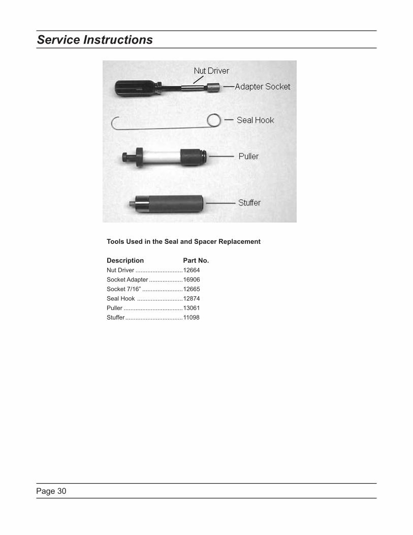
Page 30
Service Instructions
Tools Used in the Seal and Spacer Replacement
Description Part No.
Nut Driver ............................12664
Socket Adapter ....................16906
Socket 7/16” ........................12665
Seal Hook ...........................12874
Puller ...................................13061
Stuffer ..................................11098
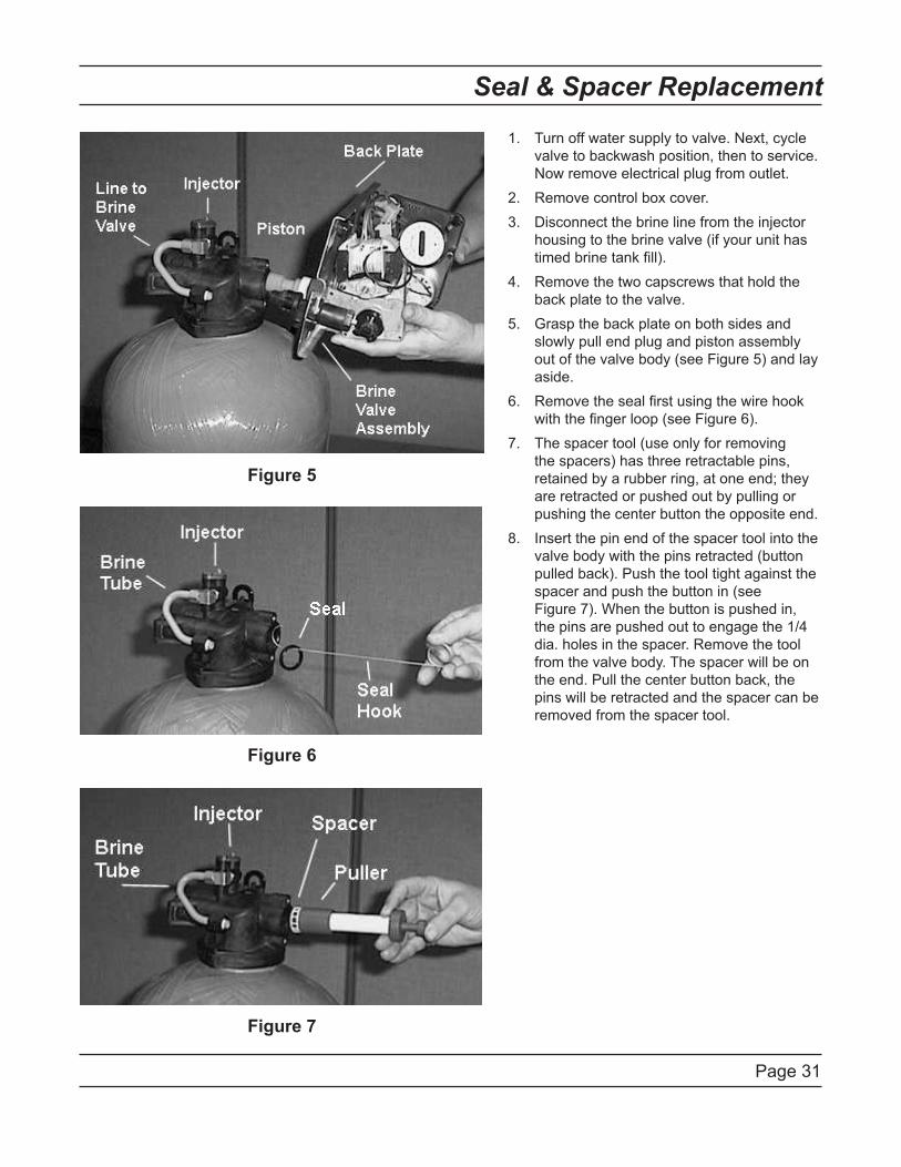
Page 31
Seal & Spacer Replacement
Turn off water supply to valve. Next, cycle 1.
valve to backwash position, then to service.
Now remove electrical plug from outlet.
Remove control box cover.2.
Disconnect the brine line from the injector 3.
housing to the brine valve (if your unit has
timed brine tank fill).
Remove the two capscrews that hold the 4.
back plate to the valve.
Grasp the back plate on both sides and 5.
slowly pull end plug and piston assembly
out of the valve body (see Figure 5) and lay
aside.
Remove the seal first using the wire hook 6.
with the finger loop (see Figure 6).
The spacer tool (use only for removing 7.
the spacers) has three retractable pins,
retained by a rubber ring, at one end; they
are retracted or pushed out by pulling or
pushing the center button the opposite end.
Insert the pin end of the spacer tool into the 8.
valve body with the pins retracted (button
pulled back). Push the tool tight against the
spacer and push the button in (see
Figure 7). When the button is pushed in,
the pins are pushed out to engage the 1/4
dia. holes in the spacer. Remove the tool
from the valve body. The spacer will be on
the end. Pull the center button back, the
pins will be retracted and the spacer can be
removed from the spacer tool.
Figure 5
Figure 6
Figure 7
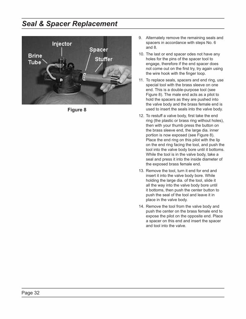
Page 32
Seal & Spacer Replacement
Alternately remove the remaining seals and 9.
spacers in accordance with steps No. 6
and 8.
The last or end spacer odes not have any 10.
holes for the pins of the spacer tool to
engage, therefore if the end spacer does
not come out on the first try, try again using
the wire hook with the finger loop.
To replace seals, spacers and end ring, use 11.
special tool with the brass sleeve on one
end. This is a double-purpose tool (see
Figure 8). The male end acts as a pilot to
hold the spacers as they are pushed into
the valve body and the brass female end is
used to insert the seals into the valve body.
To restuff a valve body, first take the end 12.
ring (the plastic or brass ring without holes),
then with your thumb press the button on
the brass sleeve end, the large dia. inner
portion is now exposed (see Figure 8).
Place the end ring on this pilot with the lip
on the end ring facing the tool, and push the
tool into the valve body bore until it bottoms.
While the tool is in the valve body, take a
seal and press it into the inside diameter of
the exposed brass female end.
Remove the tool, turn it end for end and 13.
insert it into the valve body bore. While
holding the large dia. of the tool, slide it
all the way into the valve body bore until
it bottoms, then push the center button to
push the seal of the tool and leave it in
place in the valve body.
Remove the tool from the valve body and 14.
push the center on the brass female end to
expose the pilot on the opposite end. Place
a spacer on this end and insert the spacer
and tool into the valve.
Figure 8
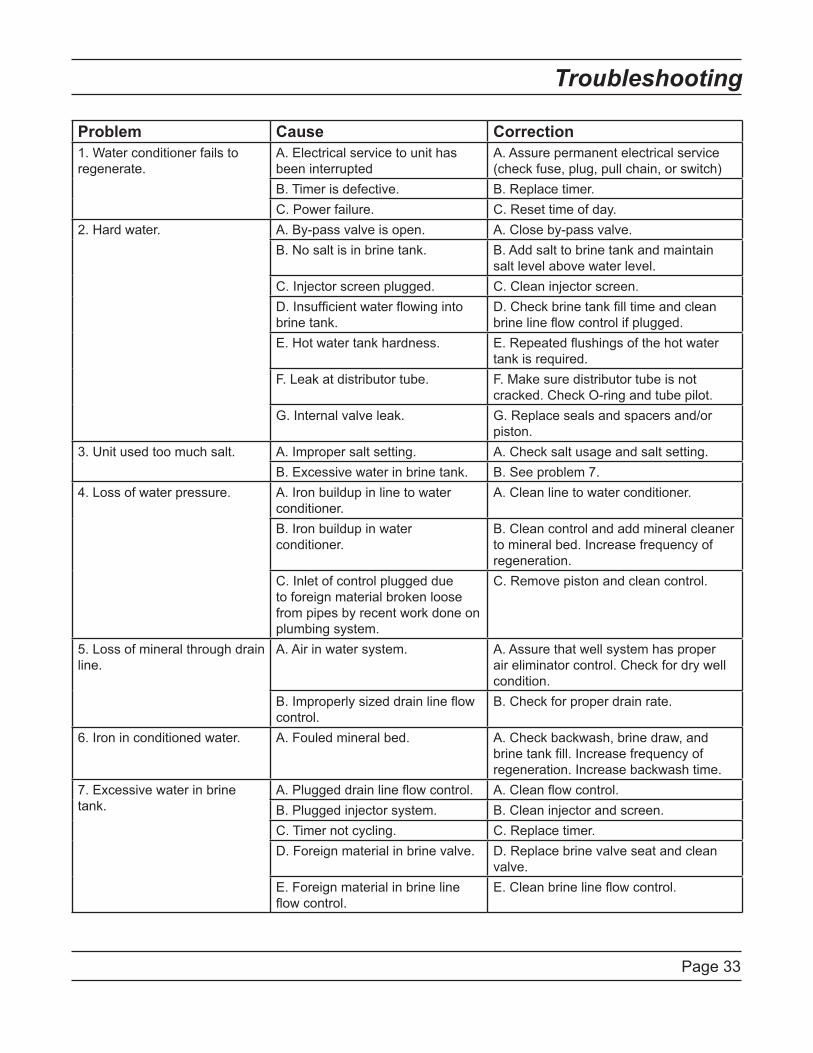
Page 33
Troubleshooting
Problem Cause Correction
1. Water conditioner fails to
regenerate.
A. Electrical service to unit has
been interrupted
A. Assure permanent electrical service
(check fuse, plug, pull chain, or switch)
B. Timer is defective. B. Replace timer.
C. Power failure. C. Reset time of day.
2. Hard water. A. By-pass valve is open. A. Close by-pass valve.
B. No salt is in brine tank. B. Add salt to brine tank and maintain
salt level above water level.
C. Injector screen plugged. C. Clean injector screen.
D. Insufficient water flowing into
brine tank.
D. Check brine tank fill time and clean
brine line flow control if plugged.
E. Hot water tank hardness. E. Repeated flushings of the hot water
tank is required.
F. Leak at distributor tube. F. Make sure distributor tube is not
cracked. Check O-ring and tube pilot.
G. Internal valve leak. G. Replace seals and spacers and/or
piston.
3. Unit used too much salt. A. Improper salt setting. A. Check salt usage and salt setting.
B. Excessive water in brine tank. B. See problem 7.
4. Loss of water pressure. A. Iron buildup in line to water
conditioner.
A. Clean line to water conditioner.
B. Iron buildup in water
conditioner.
B. Clean control and add mineral cleaner
to mineral bed. Increase frequency of
regeneration.
C. Inlet of control plugged due
to foreign material broken loose
from pipes by recent work done on
plumbing system.
C. Remove piston and clean control.
5. Loss of mineral through drain
line.
A. Air in water system. A. Assure that well system has proper
air eliminator control. Check for dry well
condition.
B. Improperly sized drain line flow
control.
B. Check for proper drain rate.
6. Iron in conditioned water. A. Fouled mineral bed. A. Check backwash, brine draw, and
brine tank fill. Increase frequency of
regeneration. Increase backwash time.
7. Excessive water in brine
tank.
A. Plugged drain line flow control. A. Clean flow control.
B. Plugged injector system. B. Clean injector and screen.
C. Timer not cycling. C. Replace timer.
D. Foreign material in brine valve. D. Replace brine valve seat and clean
valve.
E. Foreign material in brine line
flow control.
E. Clean brine line flow control.
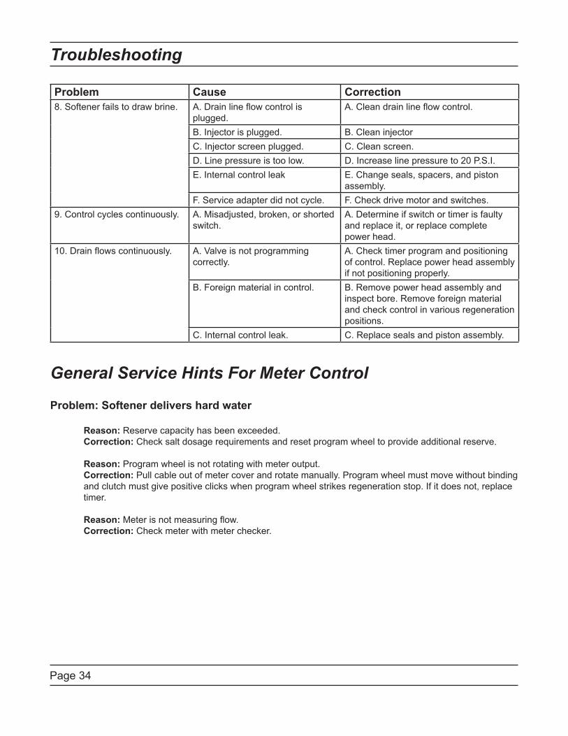
Page 34
Troubleshooting
Problem Cause Correction
8. Softener fails to draw brine. A. Drain line flow control is
plugged.
A. Clean drain line flow control.
B. Injector is plugged. B. Clean injector
C. Injector screen plugged. C. Clean screen.
D. Line pressure is too low. D. Increase line pressure to 20 P.S.I.
E. Internal control leak E. Change seals, spacers, and piston
assembly.
F. Service adapter did not cycle. F. Check drive motor and switches.
9. Control cycles continuously. A. Misadjusted, broken, or shorted
switch.
A. Determine if switch or timer is faulty
and replace it, or replace complete
power head.
10. Drain flows continuously. A. Valve is not programming
correctly.
A. Check timer program and positioning
of control. Replace power head assembly
if not positioning properly.
B. Foreign material in control. B. Remove power head assembly and
inspect bore. Remove foreign material
and check control in various regeneration
positions.
C. Internal control leak. C. Replace seals and piston assembly.
General Service Hints For Meter Control
Problem: Softener delivers hard water
Reason: Reserve capacity has been exceeded.
Correction: Check salt dosage requirements and reset program wheel to provide additional reserve.
Reason: Program wheel is not rotating with meter output.
Correction: Pull cable out of meter cover and rotate manually. Program wheel must move without binding
and clutch must give positive clicks when program wheel strikes regeneration stop. If it does not, replace
timer.
Reason: Meter is not measuring flow.
Correction: Check meter with meter checker.
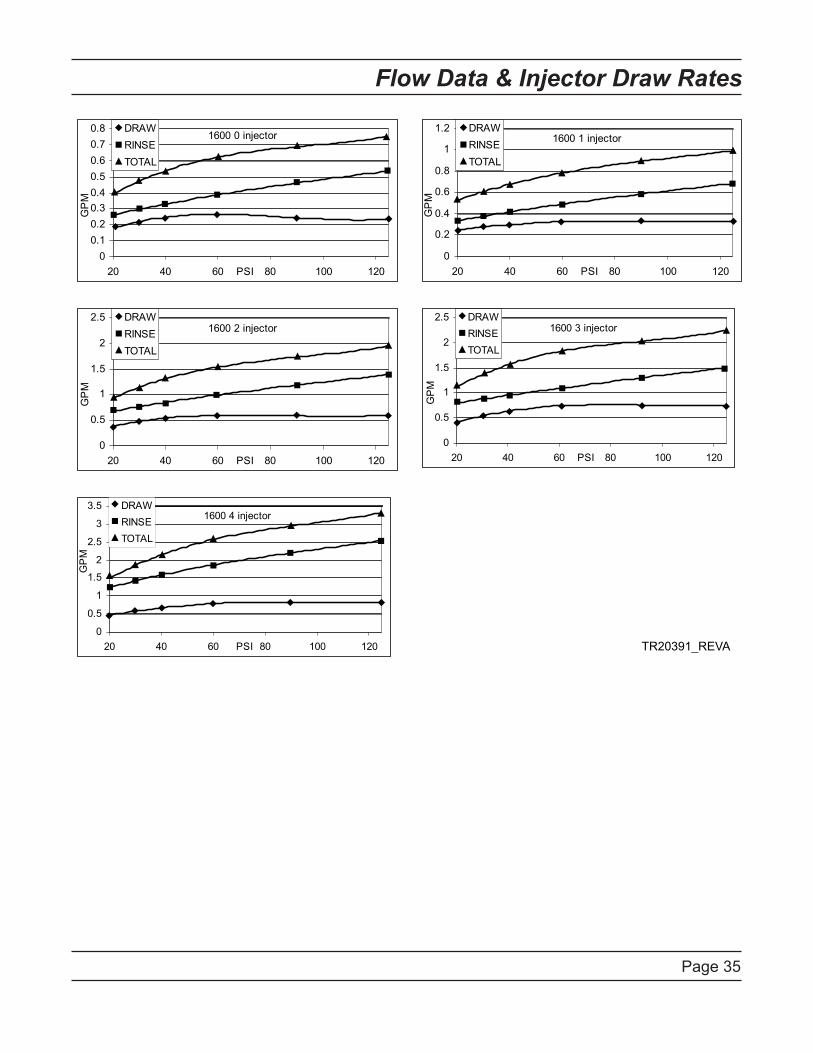
Page 35
Flow Data & Injector Draw Rates
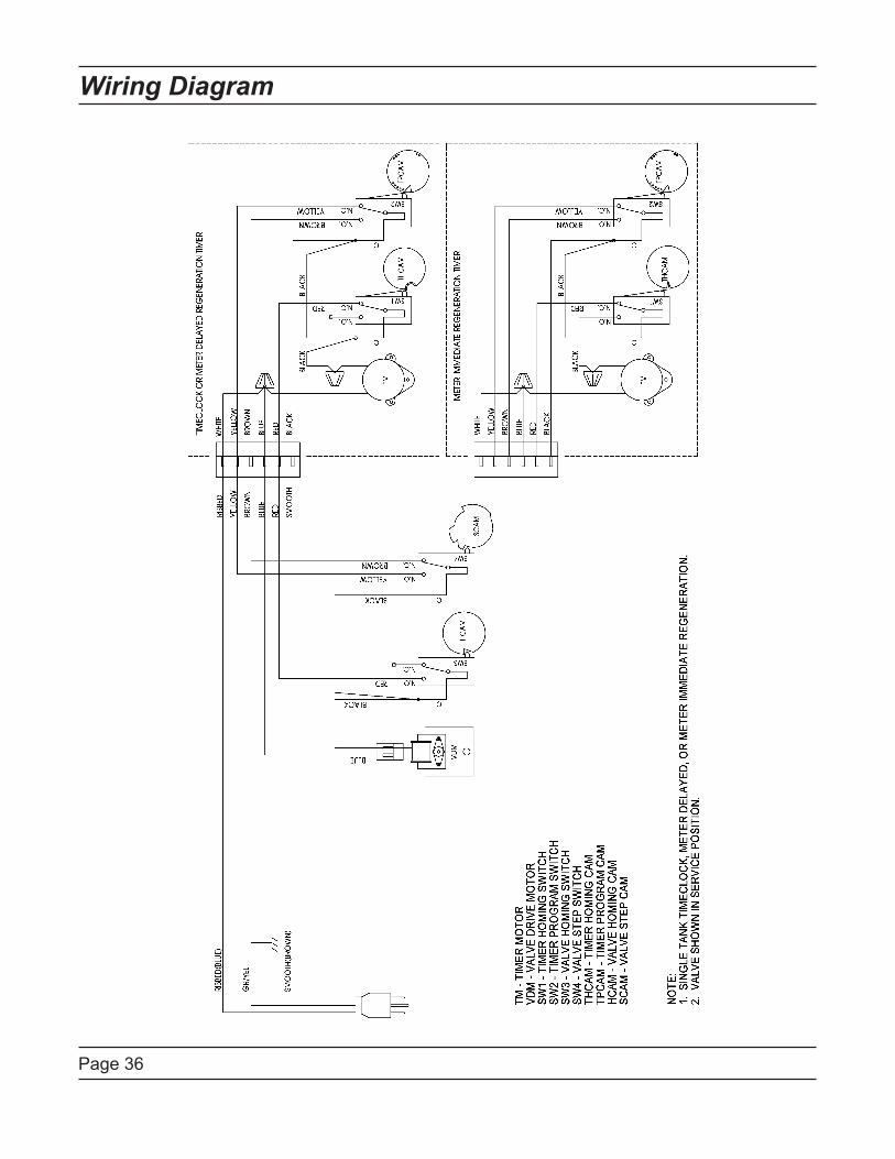
Page 36
Wiring Diagram
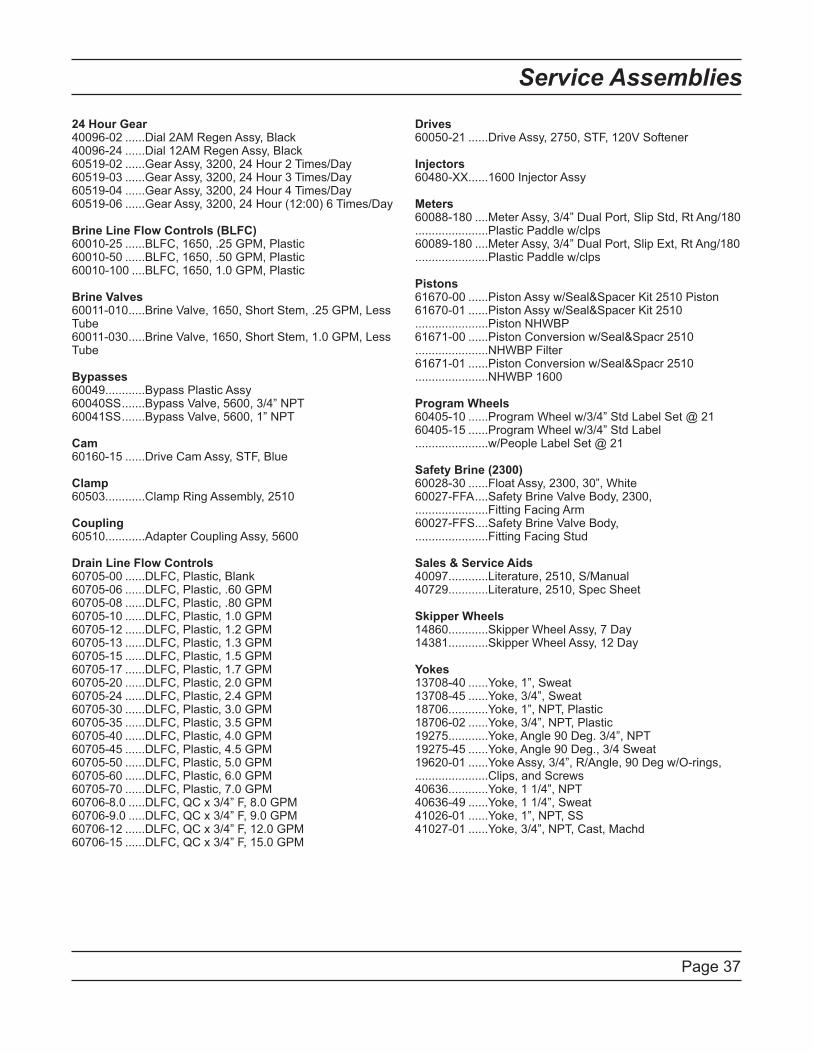
Page 37
Service Assemblies
24 Hour Gear40096-02 ......Dial 2AM Regen Assy, Black40096-24 ......Dial 12AM Regen Assy, Black60519-02 ......Gear Assy, 3200, 24 Hour 2 Times/Day60519-03 ......Gear Assy, 3200, 24 Hour 3 Times/Day60519-04 ......Gear Assy, 3200, 24 Hour 4 Times/Day60519-06 ......Gear Assy, 3200, 24 Hour (12:00) 6 Times/Day
Brine Line Flow Controls (BLFC)60010-25 ......BLFC, 1650, .25 GPM, Plastic60010-50 ......BLFC, 1650, .50 GPM, Plastic60010-100 ....BLFC, 1650, 1.0 GPM, Plastic
Brine Valves60011-010 .....Brine Valve, 1650, Short Stem, .25 GPM, Less Tube60011-030 .....Brine Valve, 1650, Short Stem, 1.0 GPM, Less Tube
Bypasses60049............Bypass Plastic Assy60040SS .......Bypass Valve, 5600, 3/4” NPT60041SS .......Bypass Valve, 5600, 1” NPT
Cam60160-15 ......Drive Cam Assy, STF, Blue
Clamp60503............Clamp Ring Assembly, 2510
Coupling60510............Adapter Coupling Assy, 5600
Drain Line Flow Controls60705-00 ......DLFC, Plastic, Blank60705-06 ......DLFC, Plastic, .60 GPM60705-08 ......DLFC, Plastic, .80 GPM60705-10 ......DLFC, Plastic, 1.0 GPM60705-12 ......DLFC, Plastic, 1.2 GPM60705-13 ......DLFC, Plastic, 1.3 GPM60705-15 ......DLFC, Plastic, 1.5 GPM60705-17 ......DLFC, Plastic, 1.7 GPM60705-20 ......DLFC, Plastic, 2.0 GPM60705-24 ......DLFC, Plastic, 2.4 GPM60705-30 ......DLFC, Plastic, 3.0 GPM60705-35 ......DLFC, Plastic, 3.5 GPM60705-40 ......DLFC, Plastic, 4.0 GPM60705-45 ......DLFC, Plastic, 4.5 GPM60705-50 ......DLFC, Plastic, 5.0 GPM60705-60 ......DLFC, Plastic, 6.0 GPM60705-70 ......DLFC, Plastic, 7.0 GPM60706-8.0 .....DLFC, QC x 3/4” F, 8.0 GPM60706-9.0 .....DLFC, QC x 3/4” F, 9.0 GPM60706-12 ......DLFC, QC x 3/4” F, 12.0 GPM60706-15 ......DLFC, QC x 3/4” F, 15.0 GPM
Drives60050-21 ......Drive Assy, 2750, STF, 120V Softener
Injectors60480-XX......1600 Injector Assy
Meters60088-180 ....Meter Assy, 3/4” Dual Port, Slip Std, Rt Ang/180 ......................Plastic Paddle w/clps60089-180 ....Meter Assy, 3/4” Dual Port, Slip Ext, Rt Ang/180 ......................Plastic Paddle w/clps
Pistons61670-00 ......Piston Assy w/Seal&Spacer Kit 2510 Piston61670-01 ......Piston Assy w/Seal&Spacer Kit 2510 ......................Piston NHWBP61671-00 ......Piston Conversion w/Seal&Spacr 2510 ......................NHWBP Filter61671-01 ......Piston Conversion w/Seal&Spacr 2510 ......................NHWBP 1600
Program Wheels60405-10 ......Program Wheel w/3/4” Std Label Set @ 2160405-15 ......Program Wheel w/3/4” Std Label ......................w/People Label Set @ 21
Safety Brine (2300)60028-30 ......Float Assy, 2300, 30”, White60027-FFA ....Safety Brine Valve Body, 2300,......................Fitting Facing Arm60027-FFS....Safety Brine Valve Body,......................Fitting Facing Stud
Sales & Service Aids40097............Literature, 2510, S/Manual40729............Literature, 2510, Spec Sheet
Skipper Wheels14860............Skipper Wheel Assy, 7 Day14381............Skipper Wheel Assy, 12 Day
Yokes13708-40 ......Yoke, 1”, Sweat13708-45 ......Yoke, 3/4”, Sweat18706............Yoke, 1”, NPT, Plastic18706-02 ......Yoke, 3/4”, NPT, Plastic19275............Yoke, Angle 90 Deg. 3/4”, NPT19275-45 ......Yoke, Angle 90 Deg., 3/4 Sweat19620-01 ......Yoke Assy, 3/4”, R/Angle, 90 Deg w/O-rings, ......................Clips, and Screws40636............Yoke, 1 1/4”, NPT40636-49 ......Yoke, 1 1/4”, Sweat41026-01 ......Yoke, 1”, NPT, SS41027-01 ......Yoke, 3/4”, NPT, Cast, Machd

Page 38
Notes

Page 39
Notes

P/N 40097 Rev. H 9/04/08