
FLC for DTC of induction motor driven by MC with Speed...
5
Journal of Engineering Science and Technology Review 9 (1) (2016) 177 - 181 Research Article Fuzzy Logic Controller for Sensorless Direct Torque Control of an Induction Motor Driven by a Matrix Converter El Mehdi Chiali 1,* , Ahmed Massoum 1 , Salah Hanafi 1 and Nabil Taib 2 1 ICEPS Laboratory (Intelligent Control & Electrical Power Systems), Djillali Liabes University of Sidi Bel-Abbes. Sidi Bel-Abbes, Algeria, E-mail: 2 L.T.I.I. Laboratory,University of Bejaia, Bejaia 06000, Algeria Received 4 May 2015; Accepted 26 October 2015 ___________________________________________________________________________________________ Abstract The direct torque control has become one of the control techniques used for high performances. The major drawback of this strategy is its high torque ripples. This paper proposes the use of matrix converter to reduce the electromagnetic torque ripples, by suitably selecting switching configuration. This switching strategy combines the advantages of matrix converter with the advantages of direct torque control technique, using a fuzzy speed controller and MRAS speed estimator. A speed controller is designed according to the concept of fuzzy logic, to provide a good robustness to the variations of mechanical parameters. A MRAS speed estimator is also used in order to avoid the implementation of a incremental encoder.The obtained results with Matlab-Simulink show the effectiveness of the proposed system. Keywords: Induction Motor, Direct Torque Control (DTC), Fuzzy Logic Controller (FLC), Matrix Converter (MC), Model Reference Adaptive (MRAS). ___________________________________________________________________________________________ 1. Introduction Due to their ease of manufacture and maintenance, induction motors are widely used in industry.Currently, many industrial applications require speed control, position and torque. However a three-phase power system does not allow these commands, because of its constant amplitude and frequency. To this end, the use of power converter is necessary. Three phase matrix converter has received considerable attention in recent years. Some advantages of the matrix converter can be seen as following: the use of a compact voltage source, providing sinusoidal voltage with varying amplitude and frequency besides the sinusoidal input current and unity input power factor at power supply side. A matrix converter has a simple topology and a compact design due to the lack of dc-link capacitor for energy storage[1].It is able to connect each input phase to each output phase via nine bidirectional switches Fig. 1 [2]. Various methods for controlling the matrix converter have been proposed such as the modulation of scalar, also called modulation Venturini[3, 4] ,or space Vector modulation the most widely used [1, 5]. The strategy of direct torque control (DTC) allows a decoupled control of flux and torque to obtain the performance of a DC machine with separate excitation[6] . The main advantages of DTC are robust and fast torque response, no requirements for coordinate transformation, no requirements for PWM pulse generation and current regulators [7]. The switching can be fixed with upplying a modulated hysteresis as proposed in [8]. In this paper a control technique for matrix converter generate, under unity input power factor conditions, voltage vectors needed to control the torque and flux of induction motors . this technique of DTC with matrix converter has already been proposed in several articles[3, 9, 10] but without speed regulation loop which is very important in industry. x Fig. 1 Matrix converter. Switches are characterized by equation (1): ⎪ ⎩ ⎪ ⎨ ⎧ = + + = + + = + + 1 1 1 cC S bC S aC S cB S bB S aB S cA S bA S aA S (1) closed is open is ij S switch ij S switch if if ij S ⎩ ⎨ ⎧ = 1 0 N I a M AS N V c N V V a I b I c I I I A V A N V B N V C N S a S b S c S a S b S c S a S b S c Jestr JOURNAL OF Engineering Science and Technology Review www.jestr.org ______________ * E-mail address: [email protected] ISSN: 1791-2377 © 2016 Eastern Macedonia and Thrace Institute of Technology. All rights reserved.
-
Upload
nguyenduong -
Category
Documents
-
view
215 -
download
1
Transcript of FLC for DTC of induction motor driven by MC with Speed...

Journal of Engineering Science and Technology Review 9 (1) (2016) 177 - 181
Research Article
Fuzzy Logic Controller for Sensorless Direct Torque Control of an Induction Motor Driven by a Matrix
Converter
El Mehdi Chiali1,*, Ahmed Massoum1, Salah Hanafi 1 and Nabil Taib2
1ICEPS Laboratory (Intelligent Control & Electrical Power Systems), Djillali Liabes University of Sidi Bel-Abbes. Sidi Bel-Abbes, Algeria, E-mail:
2L.T.I.I. Laboratory,University of Bejaia, Bejaia 06000, Algeria
Received 4 May 2015; Accepted 26 October 2015 ___________________________________________________________________________________________ Abstract The direct torque control has become one of the control techniques used for high performances. The major drawback of this strategy is its high torque ripples. This paper proposes the use of matrix converter to reduce the electromagnetic torque ripples, by suitably selecting switching configuration. This switching strategy combines the advantages of matrix converter with the advantages of direct torque control technique, using a fuzzy speed controller and MRAS speed estimator. A speed controller is designed according to the concept of fuzzy logic, to provide a good robustness to the variations of mechanical parameters. A MRAS speed estimator is also used in order to avoid the implementation of a incremental encoder.The obtained results with Matlab-Simulink show the effectiveness of the proposed system. Keywords: Induction Motor, Direct Torque Control (DTC), Fuzzy Logic Controller (FLC), Matrix Converter (MC), Model Reference Adaptive (MRAS). ___________________________________________________________________________________________
1. Introduction Due to their ease of manufacture and maintenance, induction motors are widely used in industry.Currently, many industrial applications require speed control, position and torque. However a three-phase power system does not allow these commands, because of its constant amplitude and frequency. To this end, the use of power converter is necessary. Three phase matrix converter has received considerable attention in recent years. Some advantages of the matrix converter can be seen as following: the use of a compact voltage source, providing sinusoidal voltage with varying amplitude and frequency besides the sinusoidal input current and unity input power factor at power supply side. A matrix converter has a simple topology and a compact design due to the lack of dc-link capacitor for energy storage[1].It is able to connect each input phase to each output phase via nine bidirectional switches Fig. 1 [2]. Various methods for controlling the matrix converter have been proposed such as the modulation of scalar, also called modulation Venturini[3, 4] ,or space Vector modulation the most widely used [1, 5]. The strategy of direct torque control (DTC) allows a decoupled control of flux and torque to obtain the performance of a DC machine with separate excitation[6] . The main advantages of DTC are robust and fast torque response, no requirements for coordinate transformation, no requirements for PWM pulse generation and current regulators [7]. The switching can be fixed with upplying a modulated hysteresis as proposed in [8]. In this paper a control technique for matrix converter generate, under unity input power factor conditions, voltage
vectors needed to control the torque and flux of induction motors . this technique of DTC with matrix converter has already been proposed in several articles[3, 9, 10] but without speed regulation loop which is very important in industry.
x Fig. 1 Matrix converter. Switches are characterized by equation (1):
⎪⎩
⎪⎨
⎧
=++=++=++
111
cCSbCSaCScBSbBSaBScASbASaAS
(1)
closedisopenis
ijSswitchijSswitch
ifif
ijS⎩⎨⎧
=10
N
Ia
MAS
N
Vc
N
VbN
Va
N Ib
Ic
IC
IB
IA VA
N VB
N VC
N
Sa
A
Sb
A
Sc
A
Sa
B
Sb
B
Sc
B
Sa
C
Sb
C
Sc
C
Jestr JOURNAL OF Engineering Science and Technology Review
www.jestr.org
______________ * E-mail address: [email protected] ISSN: 1791-2377 © 2016 Eastern Macedonia and Thrace Institute of Technology. All rights reserved.

El Mehdi Chiali, Ahmed Massoum, Salah Hanafi and Nabil Taib/ Journal of Engineering Science and Technology Review 9 (1) (2016) 52-55
178
2. Direct Torque Control with Matrix Converter 2.1. Basic DTC Principles Several research works have been published on the principle of the DTC [6, 11]. The DTC model is developed in the fixed coordinate system connected to the stator (α, β), we can write equations of voltage VS and stator flux φS respectively :
tssIsRsV d
dϕ+= (2)
( ) ∫ −=t
0t)sIsRs(Vts dϕ (3)
The expression of electromagnetic torque can be written as:
)sIsP(23
eC ∧= ϕ (4)
The mechanical equation of the induction machine can be written as follows:
rrfrCeCrJ Ω−−=⋅Ω (5)
2.2. Principles of DTC Using Matrix Converter The matrix converter generates a higher number of output voltage vectors with respect to voltage source inverter (VSI).
Fig. 2. Principle of DTC with a matrix converter. As there are always two voltage vectors which may be chosen for one given combination of flux and torque this gives the possibility to control the average value of the sine of the displacement angle between the input line-to-neutral voltage vector and the corresponding input line current vector Fig.2 . A mathematical model of the MC can be derived from Fig. 1 as follows:
⎥⎥⎥
⎦
⎤
⎢⎢⎢
⎣
⎡⋅
⎥⎥⎥
⎦
⎤
⎢⎢⎢
⎣
⎡=
⎥⎥⎥
⎦
⎤
⎢⎢⎢
⎣
⎡
cNVbNVaNV
cCSbCSaCScBSbBSaBScASbASaAS
CNVBNVANV
(6)
⎥⎥⎥
⎦
⎤
⎢⎢⎢
⎣
⎡⋅
⎥⎥⎥
⎦
⎤
⎢⎢⎢
⎣
⎡=
⎥⎥⎥
⎦
⎤
⎢⎢⎢
⎣
⎡
CNIBNIANI
cCScBScASbCSbBSbASaCSaBSaAS
cNIbNIaNI
(7)
From equation (1) , 27 possible configurations of switching are obtained, among them only 18 vectors can be used (±1,±2,...,±9) when two outputs are connected to the same input.These vectors are distributed on 6 directions as shown in Fig. 3.
a) voltages vectors
b) current vectors Fig. 3 Vector diagrams
wr
wr ref
Ce_ref
eC
Fuzzy controller
sector
ϕs
ϕs ref
Cᴪ Dephasing input
MRAS MAS
Ias Ibs
Vas Vbs
Va , Vb ,Vc
Sele
ctin
g a
conf
igur
atio
n
Determination Of Sector Vi
1
2 3
4
5 6

El Mehdi Chiali, Ahmed Massoum, Salah Hanafi and Nabil Taib/ Journal of Engineering Science and Technology Review 9 (1) (2016) 52-55
179
Assuming that V6 is the output voltage vector selected by the DTC classic algorithm,from the Fig. 3, it is clear that one of the switching states ± 4, ± 5 or ± 6 must be selected. Given that the magnitude and direction of these vectors depends on the input phase voltage vector,only those with the same direction of V6 and the maximum magnitude will be considered.If the voltage vectors are single in sector 6, the switching state -4 and +5 can be chosen. If an increase in the power factor is necessary ,the average value of sin (ᴪ) must be reduced, the switching state -4 Must be selected. On the other hand, if a decrease in the power factor is required, the average value of sin (ᴪ) must be increased, the switching state +5 must be selected. [9]. This technique is shown in Table 2. Table 2 The switching table for dtc with matrix converter
Values indicated by Table 2 cᴪ V1 V2 V3 V4 V5 V6
Sect
or in
whi
ch th
e ve
ctor
is in
put
volta
ges
1 +1 -3 +9 -6 +3 -9 +6 -1 +1 -7 +4 -1 +7 -4
2 +1 +2 -8 +5 -2 +5 -5 -1 -3 +9 -6 +3 -9 +6
3 +1 -1 +7 -4 +1 -7 +4 -1 +2 -8 +5 -2 +8 -5
4 +1 +3 -9 +6 -3 +9 -6 -1 -1 +7 -4 +1 -7 +4
5 +1 -2 +8 -5 +2 -8 +5 -1 +3 -9 +6 -3 +9 -6
6 +1 +1 -7 +4 -1 +7 -4 -1 -2 +8 -5 +2 -8 +5
3. Speed Loop Estimation For the speed loop we replaced the incremental encoder by MRAS estimator from which we obtain the estimated speed from stator current and voltage induction motor. This technique is used not only to reduce the cost of the system, but also to eliminate needs additional space for mounting and maintenance of the incremental encoder. To ensure the speed control we used a fuzzy controller which is insenssible to machine parametric variation and also in order to reduce the response time for speed. 3.1. Model Reference Adaptive System The MRAS (model reference adaptive system) is based on comparing the outputs of two estimators. The first , which does not introduce the quantity to estimate (the speed in this case) is called the reference model and the second is the adjustable model [12]. PI regulator has the role of an adaptation mechanism to generate the estimated speed, as shown in Fig. 4. 3.2. Five Rules Fuzzy Logic Controller FLC requires some arbitrary decisions concerning rule base, input and output membership functions. This makes the design procedure strongly dependent on expert knowledge [13].Fig. 5 shows the schematic model of FLC based speed regulator.
Fig.4. Block diagram of the MRAS estimator.
Fig. 5 The structure of Fuzzy logic control . In the fuzzy membership,the speed error(e), and change in error(∆e) are considered input variables of the FLC, and each input variable have five linguistic values. The fuzzy control rules are shown in Table 3. Table 3.Fuzzy control rules
e
Δ e
NL
NS
ZE
PS
PL
NL NL NL NL NS ZE NS NL NL NS ZE PS ZE NL NS ZE PS PL PS NS ZE PS PL PL PL ZE PS PL PL PL
The model is presented as follow:
rwref rwe −= and 1)e(ke(k)Δe(k) −−=
Where wr ref is the reference speed and wr is the actual speed of rotor, e(k) is the error and ∆e(k) is the error change.Then the output variable of the FLC is presented by the reference torque control Ce ref . 7. Simulation Results and Interpretation The whole system has been simulated using the Matlab-Simulink package. The machine used for simulation is a three-phase 1.5 KW induction motor with the following parameters shown in Table 4. Table 4Induction Motor Parameters
P 1.5 kw Rr 3.81 Ω U 380 v Ls,Lr 0.274 H N 1450 tr/min M 0.258 H P 2 J 0.031 kgm2 Rs 4.85 Ω fr 0.0114
Nm/rd/s
Reference model
Ajustable model
Adaptative mechanisme
rαφ
rβφ
rαφ̂
rβφ̂
sV
sI
+−
sIrTM
rrwprrT1
tr ++−= ϕϕϕ ˆdˆd
SKiKp +
)dd
dd
tsI
sσLsIsRs(VMrL
tr −−=
ϕ
El Mehdi Chiali, Ahmed Massoum, Salah Hanafi and Nabil Taib/ Journal of Engineering Science and Technology Review 9 (1) (2016) 52-55
180
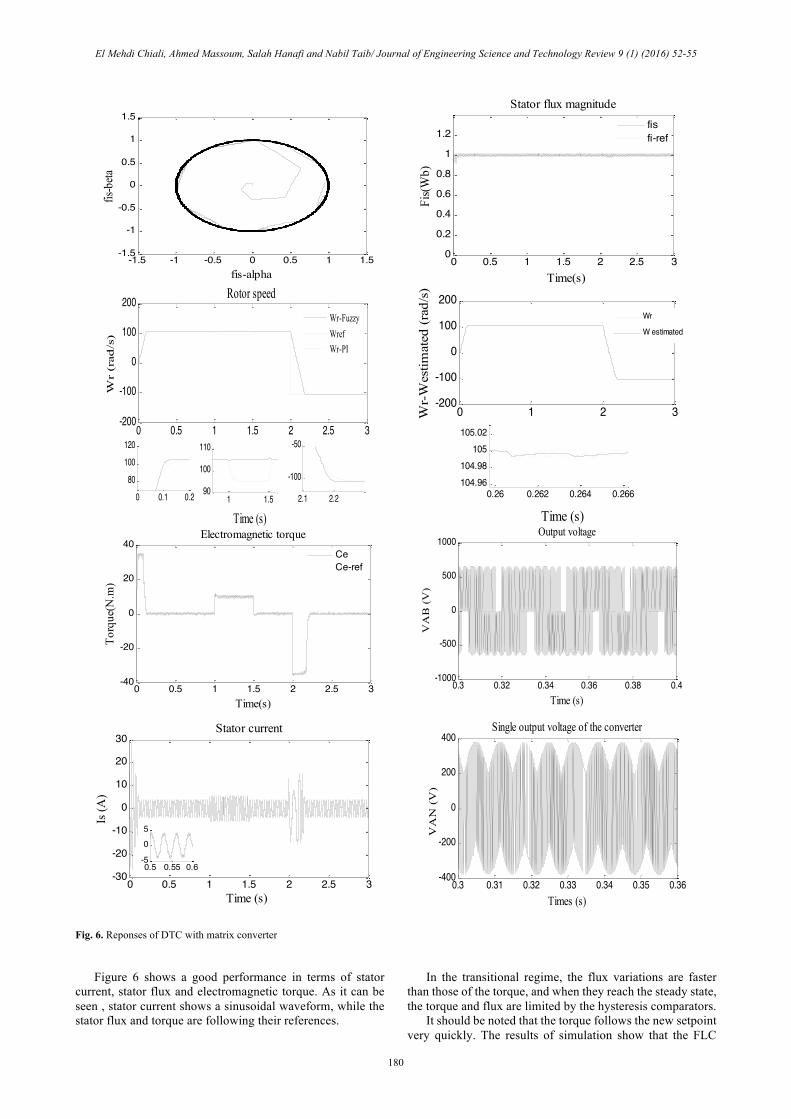
Fig. 6. Reponses of DTC with matrix converter Figure 6 shows a good performance in terms of stator current, stator flux and electromagnetic torque. As it can be seen , stator current shows a sinusoidal waveform, while the stator flux and torque are following their references.
In the transitional regime, the flux variations are faster than those of the torque, and when they reach the steady state, the torque and flux are limited by the hysteresis comparators. It should be noted that the torque follows the new setpoint very quickly. The results of simulation show that the FLC
0 0.5 1 1.5 2 2.5 3-30
-20
-10
0
10
20
30
Time (s)
Is (A
)
Stator current
0.5 0.55 0.6-5
05
-1.5 -1 -0.5 0 0.5 1 1.5-1.5
-1
-0.5
0
0.5
1
1.5
fis-alpha
fis-beta
0 0.5 1 1.5 2 2.5 3-200
-100
0
100
200
Time (s)
Wr
(rad
/s)
Rotor speed
0 0.1 0.280
100120
1 1.590
100
110
Wr-FuzzyWrefWr-PI
2.1 2.2
-100
-50
0 0.5 1 1.5 2 2.5 30
0.2
0.4
0.6
0.8
1
1.2
Time(s)
Fis(
Wb)
Stator flux magnitude
fisfi-ref
0 1 2 3-200
-100
0
100
200
Time (s)
Wr-
Wes
timat
ed (r
ad/s
)
0.26 0.262 0.264 0.266104.96104.98
105105.02
Wr
W estimated
0 0.5 1 1.5 2 2.5 3-40
-20
0
20
40
Time(s)
Torq
ue(N
.m)
Electromagnetic torque
CeCe-ref
0.3 0.31 0.32 0.33 0.34 0.35 0.36-400
-200
0
200
400Single output voltage of the converter
Times (s)
VA
N (
V)
0.3 0.32 0.34 0.36 0.38 0.4-1000
-500
0
500
1000Output voltage
Time (s)
VA
B (
V)

El Mehdi Chiali, Ahmed Massoum, Salah Hanafi and Nabil Taib/ Journal of Engineering Science and Technology Review 9 (1) (2016) 52-55
181
gives better responses compared to a conventional PI controller. The time response speed is very good without overshoot. Moreover, the corresponding values are represented in Table 5. Table 5. Performance of Controllers at Load
Controller Type Settling Time (ms)
PI Controller 200 ms 600 ms(response to load torque)
FLC 144 ms 40 ms(response to load torque)
Knowing that the speed response given by the MRAS estimator is almost the same to the actual speed. The only major drawback is that the matrix converter output voltage is limited to 86.6% of the input voltage. 8. Conclusion
The basic idea of the work presented is the performances analysis of the DTC applied to induction machine fed by matrix converter. The speed regulation loop contains both of a speed MRAS estimator and FLC regulator. The direct torque control of an induction machine provides a satisfactory solution to electric drives problems in terms of robustness and dynamics encountered in control techniques based on the orientation of the rotor flux using voltage source inverters. The use of matrix converter allowed an improvement in the DTC performances aiming to reduce torque oscillations because of the best quality of the input and output waveforms provided.In addition, FLC regulator proves its good performance for speed regulation of induction motor shown by the obtained results. This latter, gives an added value to the electrical machine drive. Moreover, the MRAS based speed estimator allows reduced cost and size of the control system.The advantages provided by the proposed system make it competitive with regard to the other proposed solutions.
______________________________ References
1. H.M.Nguyen , H-H Lee , T-W Chun , A Novel DTC-SVM Method Using Matrix Converter Fed Induction Motor, Industrial Technology, 2009. ICIT 2009. IEEE International
2.F.Gruson ,Modulation naturelle généralisée des convertisseur matriciels pour la variation de vitesse,PRES-Université Lille Nord de France 13 décembre 2010.
3.H.Karaca, R.Akkaya, Control of Venturini Method Based Matrix Converter in Input Voltage Variations, Proceedings of the International MultiConference of Engineers and Computer Scientists 2009 Vol II IMECS 2009, March 18 - 20, 2009, Hong Kong.
4.S. Bernet, S. Ponnaluri, and R. Teichmann, Design and loss comparison of matrix converters, and voltage-source converters for modern AC drives, IEEE Trans. Ind. Electron., vol. 49, no. 2, pp. 304–314,Apr. 2002.
5.K.B.Lee ;F.Blaabjerg , Sensorless DTC-SVM for Induction Motor Drivenby a Matrix Converter Using a ParameterEstimation Strategy, Industrial Electronics, IEEE Transactions on Vol. 55 , No. 2 february 2008.
6.L.Youb, Aurelian Craciunescu, Commande Directe du Couple et Commande Vectorielle de la Machine Asynchrone, Rev. Roum. Sci. Techn. – Électrotechn. et Énerg., 53, 1,p. 87–98, Bucarest, 2008.
7.D.Casadei, G.Serra, A.Tani, The Use of Matrix Converters in Direct Torque Control of Induction Machines, IEEE Transaction On Industrial Electronics, Vol.48,No.6, December 2001.
8. N. Taib, B. Metidji, T. Rekioua, A Fixed Switching Frequency Direct Torque Control Strategy for Induction Motor Drives Using Indirect Matrix Converter, Arabian Journal for Science and Engineering (AJSE), Vol. 39, no. 3, pp. 2001-2011, March, 2014.
9. C. Ortega , A. Arias , J.L. Romeral , E. Aldabas ,Direct Torque Control for Induction Motors Using Matrix Converters ,Industrial Electronics Society,2005.IECON 2005 . 31 st Annual Conférence of IEEE.
10.J.Boll, F.W.Fuchs, Direct Control Methods for Matrix Converter and Induction Machine Industrial Electronics, 2005. ISIE 2005. Publication Year: 2005 , Page(s): 781 - 787 vol. 2 .
11.H.Yantour, J.Saadi, A.Khoumsi, A Hybrid System based approach to Direct Torque Control (DTC) of Induction Motors , 2010 , Page(s): 327 - 332 IEEE Conference Publications.
12.E.Chiali, A.Massoum, A.Guebli, S.Hanafi Sensorless Direct Torque Control of an Induction Machine driven by a Matrix Inverter with Speed estimator, International Journal of Advanced Engineering and Science, Vol. 2, No.2, 2013.
13.F.Daya.JL, V.Subbiah, A Novel Fuzzy Logic Based Robust Speed Controller for Permanent Magnet Synchronous Motor Servo Drive, 2009
Appendix
sR , rR :Stator and rotor inductance.
sL :Stator inductance M :Mutual inductance.
rT :Rotor time constant.
eC :Electromagnetic torque.
rC :Resistive torque.
sϕ :Stator flux. P :Pole pairs. J :Moment of inertia.
rΩ :Rotor speed.
rw :Rotor angular frequency.