Dynamic mechanical properties of geopolymer-polymer composites.pdf

SAND REPORT
SAND2003-8307 Unlimited Release Printed July 2003 FLASHFOAM: A Triboluminescent Polymer Foam for Mechanical Sensing
S. H. Goods, P. M. Dentinger, and L. L Whinnery Prepared by Sandia National Laboratories Albuquerque, New Mexico 87185 and Livermore, California 94550 Sandia is a multiprogram laboratory operated by Sandia Corporation, a Lockheed Martin Company, for the United States Department of Energy’s National Nuclear Security Administration under Contract DE-AC04-94-AL85000. Approved for public release; further dissemination unlimited.

NOTICE: This report was prepared as an account of work sponsored by an agency of the United States Government. Neither the United States Government, nor any agency thereof, nor any of their employees, nor any of their contractors, subcontractors, or their employees, make any warranty, express or implied, or assume any legal liability or responsibility for the accuracy, completeness, or usefulness of any information, apparatus, product, or process disclosed, or represent that its use would not infringe privately owned rights. Reference herein to any specific commercial product, process, or service by trade name, trademark, manufacturer, or otherwise, does not necessarily constitute or imply its endorsement, recommendation, or favoring by the United States Government, any agency thereof, or any of their contractors or subcontractors. The views and opinions expressed herein do not necessarily state or reflect those of the United States Government, any agency thereof, or any of their contractors. Printed in the United States of America. This report has been reproduced directly from the best available copy. Available to DOE and DOE contractors from
U.S. Department of Energy Office of Scientific and Technical Information P.O. Box 62 Oak Ridge, TN 37831 Telephone: (865)576-8401 Facsimile: (865)576-5728 E-Mail: [email protected] Online ordering: http://www.doe.gov/bridge
Available to the public from
U.S. Department of Commerce National Technical Information Service 5285 Port Royal Rd Springfield, VA 22161 Telephone: (800)553-6847 Facsimile: (703)605-6900 E-Mail: [email protected] Online order: http://www.ntis.gov/help/ordermethods.asp?loc=7-4-0#online

SAND2003-8307 Unlimited Release Printed July 2003
FLASHFOAM:
A Triboluminescent Polymer Foam for Mechanical Sensing
S. H. Goods, Microsystem Materials and Mechanics, 8725,
P. M. Dentinger and L. L. Whinnery, Materials Chemistry, 8722 Sandia National Laboratories
P.O. Box 969, MS9404 Livermore, CA 94551-0969
ABSTRACT
The formulation and processing of a brittle polyurethane foam containing triboluminescent powder additives is described. Two powder additives, known to exhibit triboluminescence, were individually examined: triethylammonium tetrakis (dibenzoylmethanato) europate [NEt3H][Eu(DBM)4] and ordinary table sugar (sucrose, C12H22O11). In each instance, the powders were mixed into the polyol component of the foam. When combined with the isocyanate component, the resulting foams had these powders incorporated into their cellular structure so as to induce a triboluminescent response upon crushing during impact testing. The triboluminescent response of foam specimens containing each of these powder additives was characterized by measuring:
the time rate of change in the optical output (measured as Watts), the peak optical output, the total integrated output (Watt-seconds), during the impact event.
Foams containing the europate compound were found to yield several orders of magnitude higher output when compared to the sugar-containing foam. Strain rate and concentration of the powder (in the foam) were important variables with respect to optical output. Both the peak and total triboluminescent output increased with increasing powder concentration. Peak output was also found to increase with increasing strain rate. However, the total output was found to be roughly constant for a given concentration regardless of strain rate (over the strain rate range: 20 sec-1< ε& < 150 sec-1). At very low strain rates, no triboluminescent response was measured.
1

This page intentionally left blank
2

C O N T E N T S
ABSTRACT...........................................................................................................................1
I. Introduction.........................................................................................................................4
II. Experimental .....................................................................................................................5
Eu synthesis........................................................................................................................5 Brittle Foam Formulation...................................................................................................5 Particle Loaded Foams.......................................................................................................6 Mechanical Testing ............................................................................................................6
III. Results ..............................................................................................................................7
Structure and Composition of the TL Materials ................................................................7 Mechanical and Optical Response of TL Powder Loaded Foams .....................................8
IV. Discussion........................................................................................................................9
V. Summary ........................................................................................................................10
VI. Acknowledgements........................................................................................................11
VII. References ...................................................................................................................11
VIII. Figures.........................................................................................................................12
IX. Distribution ....................................................................................................................23
3
FLASHFOAM: A Triboluminescent Polymer Foam for Mechanical Sensing
I. Introduction
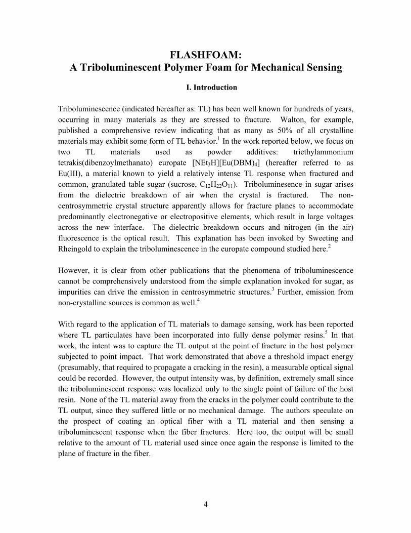
Triboluminescence (indicated hereafter as: TL) has been well known for hundreds of years, occurring in many materials as they are stressed to fracture. Walton, for example, published a comprehensive review indicating that as many as 50% of all crystalline materials may exhibit some form of TL behavior.1 In the work reported below, we focus on two TL materials used as powder additives: triethylammonium tetrakis(dibenzoylmethanato) europate [NEt3H][Eu(DBM)4] (hereafter referred to as Eu(III), a material known to yield a relatively intense TL response when fractured and common, granulated table sugar (sucrose, C12H22O11). Triboluminesence in sugar arises from the dielectric breakdown of air when the crystal is fractured. The non-centrosymmetric crystal structure apparently allows for fracture planes to accommodate predominantly electronegative or electropositive elements, which result in large voltages across the new interface. The dielectric breakdown occurs and nitrogen (in the air) fluorescence is the optical result. This explanation has been invoked by Sweeting and Rheingold to explain the triboluminescence in the europate compound studied here.2 However, it is clear from other publications that the phenomena of triboluminescence cannot be comprehensively understood from the simple explanation invoked for sugar, as impurities can drive the emission in centrosymmetric structures.3 Further, emission from non-crystalline sources is common as well.4 With regard to the application of TL materials to damage sensing, work has been reported where TL particulates have been incorporated into fully dense polymer resins.5 In that work, the intent was to capture the TL output at the point of fracture in the host polymer subjected to point impact. That work demonstrated that above a threshold impact energy (presumably, that required to propagate a cracking in the resin), a measurable optical signal could be recorded. However, the output intensity was, by definition, extremely small since the triboluminescent response was localized only to the single point of failure of the host resin. None of the TL material away from the cracks in the polymer could contribute to the TL output, since they suffered little or no mechanical damage. The authors speculate on the prospect of coating an optical fiber with a TL material and then sensing a triboluminescent response when the fiber fractures. Here too, the output will be small relative to the amount of TL material used since once again the response is limited to the plane of fracture in the fiber.
4

The concept proposed here is fundamentally different. By incorporating these materials as powders into the cellular structure of a foam, the active triboluminescent material is distributed evenly throughout a structure that uniformly collapses when deformed at high rates. Therefore, all of the TL material can respond to the mechanical event. As a result, the output sensitivity will be many times greater than that achieved on a monolithic, full density structure that fractures only along a single crack. Other benefits derive from the fact that the host foam can (1) be fabricated into any arbitrary shape or (2) be molded in-situ to fill the free volume of existing structures and (3) that foams fail at lower impact energy levels compared to solid materials. A last potential benefit derives from the fact that since the parent foam is a structural material, in principle, it can even be incorporated in the mechanical design of components. For the foam/TL material to function satisfactorily, we believe that several requirements must be met. First, the TL material must be a fine powder on the order of 5-20 µm in dimension. This is necessary so that the powder will be incorporated into the cell walls and struts of the foam macrostructure. When subjected to an abrupt mechanical load, the cell wall membranes and struts buckle, collapse and fracture. This mechanical response of the foam leads to the second requirement; that the powder must be wetted by and well bonded to the foam polymer resin. This is necessary in order to adequately transfer mechanical load to the TL material. As the foam structure fractures, either of two things may occur – the polymer/particle interfaces may separate or, the particles themselves may fracture. In either case, it is the stress transmitted to the particles that trigger their triboluminescent response. If the powder is not well bonded to the foam polymer, the stress transmission to the particulate will be inefficient and TL response will likely be reduced. The third requirement to be met involves the mechanical performance of the host foam. A foam that exhibits superior impact toughness, will undergo a significant amount of reversible cell wall/strut buckling. We believe that it is important to maximize the relative amount of irreversible, catastrophic fracture in the foam struts and cell walls so as to maximize the load transference and cracking to the TL constituent. To that end, a new polyurethane foam was specifically formulated having minimum toughness under impact conditions.
II. Experimental
Eu synthesis The europium compound was synthesized as per the literature.6
Brittle Foam Formulation In order to maximize the triboluminescent response of the Eu(III) loaded structure, a new polyurethane foam was formulated to insure uniform brittle fracture. The following were combined in a container for hand mixing:
5

5.24 g - Glycerol (Aldrich Chemical), 5.22 g - Voranol 490 (Dow Chemical), 0.32 g - DC193 (Air Products and Chemicals, Inc.), 0.10 g - Polycat17 (Air Products and Chemicals, Inc.), 0.33 g - De-ionized water 18 (MΩ)
These ingredients were thoroughly mixed with a spatula. The isocyanate:
39.45 g - Rubinate 1680 (Dow Chemical)
was added to the resin mixture and immediately and thoroughly mixed with a spatula for 1 minute. The frothy liquid was then poured into another cup or mold as desired. After a minimum of 15 minutes from the time of mixing, the foam was post-cured for approximately 2 hours at 57°C.
Particle Loaded Foams The same procedure as described above was used with the following modifications. The appropriate amount of particulate [Eu(III), sucrose, etc.] was stirred into the previously mixed resin prior to addition of the isocyanate.
Mechanical Testing Cylindrical specimens (12.5 mm diameter x 21 mm long) were machined from foam blocks. The nominal density of all specimens was 0.08 g/cm3. Specimens were tested in a Dynatup 8250 Drop Tower impact tester (Instron Corp., Canton, MA). Figure 1a shows the impact tester and at higher magnification, Figure 1b shows the specimen pedestal and holder located on the base of the impact tester. A foam specimen and the plunger are also shown outside of the holder. Specimens were placed in the holder and the flat-ended plunger was rested on the top end of the specimen cylinder. The inner diameter of the holder and the end of the plunger were polished to maximize reflectance. Clearance between the plunger and holder ID was minimized (less that 50 µm on the diameter) in order to avoid light leakage (either in or out) within the fixturing. The plunger was struck with the falling mass of the impact crosshead to compress the foam specimen. Data was collected using the high-speed DAQ system supplied by the manufacturer and with a Model LC564DL digital storage oscilloscope (LeCroy Inc., Chestnut Ridge, NY). An optical fiber was used to gather and transmit light emitted from the foam during the impact tests. The clad fiber can be seen in the slot at the bottom of the specimen pedestal
6
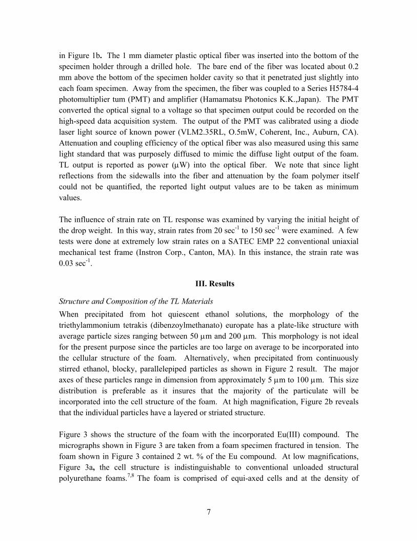
in Figure 1b. The 1 mm diameter plastic optical fiber was inserted into the bottom of the specimen holder through a drilled hole. The bare end of the fiber was located about 0.2 mm above the bottom of the specimen holder cavity so that it penetrated just slightly into each foam specimen. Away from the specimen, the fiber was coupled to a Series H5784-4 photomultiplier tum (PMT) and amplifier (Hamamatsu Photonics K.K.,Japan). The PMT converted the optical signal to a voltage so that specimen output could be recorded on the high-speed data acquisition system. The output of the PMT was calibrated using a diode laser light source of known power (VLM2.35RL, O.5mW, Coherent, Inc., Auburn, CA). Attenuation and coupling efficiency of the optical fiber was also measured using this same light standard that was purposely diffused to mimic the diffuse light output of the foam. TL output is reported as power (µW) into the optical fiber. We note that since light reflections from the sidewalls into the fiber and attenuation by the foam polymer itself could not be quantified, the reported light output values are to be taken as minimum values. The influence of strain rate on TL response was examined by varying the initial height of the drop weight. In this way, strain rates from 20 sec-1 to 150 sec-1 were examined. A few tests were done at extremely low strain rates on a SATEC EMP 22 conventional uniaxial mechanical test frame (Instron Corp., Canton, MA). In this instance, the strain rate was 0.03 sec-1.
III. Results
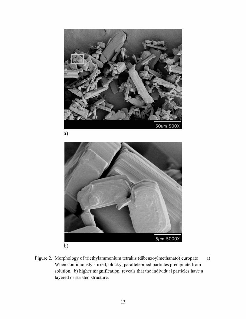
Structure and Composition of the TL Materials When precipitated from hot quiescent ethanol solutions, the morphology of the triethylammonium tetrakis (dibenzoylmethanato) europate has a plate-like structure with average particle sizes ranging between 50 µm and 200 µm. This morphology is not ideal for the present purpose since the particles are too large on average to be incorporated into the cellular structure of the foam. Alternatively, when precipitated from continuously stirred ethanol, blocky, parallelepiped particles as shown in Figure 2 result. The major axes of these particles range in dimension from approximately 5 µm to 100 µm. This size distribution is preferable as it insures that the majority of the particulate will be incorporated into the cell structure of the foam. At high magnification, Figure 2b reveals that the individual particles have a layered or striated structure. Figure 3 shows the structure of the foam with the incorporated Eu(III) compound. The micrographs shown in Figure 3 are taken from a foam specimen fractured in tension. The foam shown in Figure 3 contained 2 wt. % of the Eu compound. At low magnifications, Figure 3a, the cell structure is indistinguishable to conventional unloaded structural polyurethane foams.7,8 The foam is comprised of equi-axed cells and at the density of
7

interest, ≈ 0.08 g/cm3, the cells are typically 300 µm to 500 µm in diameter. None of the powder additive was observed within the interior of the cells. At high magnification, Figure 3b shows a Eu (III) particle embedded in a cell strut. The fracture surface of the polymer strut is to the right of the particle and is easily differentiated from the fracture surface of the Eu(III). The absence of a gap between the polymer and the particle on the fracture surface is an indication of good bonding between the matrix and the powder. In other particle-loaded foam systems poor bonding is manifested by the presence of pullouts on the fracture surface where the powder additive has separated from the matrix as well as large gaps between the additive and matrix.9 Energy dispersive spectroscopy (EDS) was used to confirm that the particulate material embedded in the foam structure was the Eu powder compound. Figure 4 shows another SEM micrograph of a fractured foam specimen. The associated spectra are taken from within a fractured particle and immediately adjacent to the particle in the polymer strut. The Eu peak is easily identified. Note that the gold and palladium peaks in each spectrum are from the conductive metallization layer that is deposited on the fracture surface. This film is required in order to image the non-conducting polymer foam in the microscope.
Mechanical and Optical Response of TL Powder Loaded Foams Figure 5 shows the results of an impact test performed on an unloaded foam specimen used as a control. Two traces are shown in this Figure. The broken trace shows the compressive stress evolution during the impact event. Because the foam had a relatively low density, little stress is generated during the early portion of the test. Only after a compressive strain of approximately 0.6 does the stress begin to increase, peaking at a value of 30-35 MPa, typical of polyurethane foams of this density (Refs. 7- 9) for example). The impact tester was configured with safety stops so that the maximum compressive strain that could be imposed on the specimen was approx. 0.8. As a result, the stress drops abruptly beyond strains of this magnitude. That there is little or no rebound of the plunger after impact indicates that the foam collapse is catastrophic and irreversible. The solid trace shows the optical output of the foam as measured using the PMT described earlier. As expected, no measurable light output was recorded. Figure 6 shows the response of a foam specimen containing 1 wt. % of the Eu powder additive. The stress-strain behavior of the foam is similar to that shown in the previous Figure. In this instance there is measurable light output as the foam is crushed during the impact event. There is a small light peak at low compression strain as the cellular structure begins to collapse. However, the majority of the light output occurs at larger strains where there is rapid increase in stress. This corresponds to the strain regime of maximum mechanical damage to the foam structure. As the impact head engages the mechanical
8

stops and decelerates, there is an abrupt decrease in the light output corresponding to unloading of the specimen. Figure 7 shows the response of a foam specimen containing 4 wt. % of the Eu powder additive. Once again, the mechanical response of the foam is similar to that shown in the previous Figures. In this instance the peak load is somewhat lower than in either of the previous two Figures, most likely the result of the foam having a slightly lower overall density. However, the optical power is clearly sensitive to the loading fraction of the Eu powder additive. Peak power is nearly threefold greater in Figure 7 than in the previous figure. Total energy, that is, the time integrated power is also found to be dependent on loading fraction of the TL powder as shown in Figure 8. Strain rate is an important variable with respect to both the peak power and total energy output. In the extreme case, Figure 9 shows the TL output for a loaded foam specimen tested under quasi-static compression conditions. In this instance, the strain rate is three orders of magnitude slower than the impact test rates show in the previous Figures. No detectable light output was measured under these conditions. Figure 10 shows the strain rate dependence for a series of foam specimens tested over a range of strain rates. The loading fraction was constant for all specimens (2 wt. %). The data shown are the average of three measurements at each strain rate and the error bars represent the standard deviation. Notwithstanding the scatter in some of the data, the trend is clear, viz., increasing strain rate yields higher peak power while the total energy emitted remains constant. Lastly, a foam was fabricated with 10 wt. % addition of sugar as the TL powder. Typical results are shown in Figure 11. While light output was detectable, the peak level was exceedingly small, roughly a thousand-fold lower level than that for the Eu compound when normalized for loading fraction. Because the level was so low, no additional tests were performed with sugar as the active TL constituent.
IV. Discussion Our initial attempts to prepare a TL foam involved adding the TL Eu(III) particles to an existing rigid, water-blown polyurethane foam. When these foams were tested, only a small amount of light was observed. We postulated that the foam was relatively tough and that a more brittle foam would result in more complete fracture of the struts and walls where the majority of the particles were located. The more brittle foam used here was formulated by substituting some of the Voranol 490 polyol with glycerol. Glycerol is a short triol with few freely rotating bonds between functional groups to dissipate energy from an impact. As expected this new foam was more brittle than the initial foam and when loaded with the TL particulate, light emission was considerably enhanced.
9

Figures 3 and 4 show that the TL powder additive was fully incorporated into the cell walls and struts that comprise the porous foam structure. In order to realize an optical response from the loaded foams, the triboluminescent powder embedded in the foam walls and struts should fracture or debond as the foam is crushed during impact. The fracture surface shown in Figure 3 reveals that the stresses required to macroscopically fracture the foam were locally sufficient to fracture the individual TL powder particles. The fracture surfaces of the loaded foam also reveal that in general, the embedded particles were well-bonded to the polymer matrix. That is, there is little evidence of interface separation between the Eu powder and the polyurethane matrix. Rather, in virtually all instances, the stresses generated in the cell walls and struts during the catastrophic collapse of the foam resulted in the fracture of the particulate additive. Thus, the three principal requirements described earlier have been satisfied: 1) the powder additive is incorporated into the cell structure of the foam, 2) the stresses generated in the foam during impact induces fracture of the embedded particles and 3) the foam collapse is catastrophic and largely irreversible. Figure 8 shows that the energy output scales linearly with loading fraction of the TL additive. It appears, therefore, the amount of light output can be easily “tuned” by simply adjusting the ratio of additive to foam pre-cursors during formulation. Figure 10 shows that for a single loading fraction of the Eu powder, the peak output increases with strain rate. This simply reflects the fact that the entire triboluminescent output is compressed into a smaller time window at the higher strain rates. The figure also shows that the total output (or energy) is nearly independent of strain rate. This indicates that, so long as the stresses generated during impact of the foam are sufficient to cause particle fracture, nearly all of the incorporated powder contributes to the TL output of a loaded specimen. At a minimum, the fraction of particles contributing to light output is independent of strain rate.
V. Summary A novel triboluminescent material consisting of a cellular polymer foam containing a uniform distribution of triethylammonium tetrakis(dibenzoylmethanato) europate particulate has been demonstrated. This material is straightforward to synthesize and fabricate into simple geometries. Strain rate and concentration of the powder (in the foam) were important variables with respect to optical output. Both the peak and total triboluminescent output increased with increasing powder concentration. Peak output was also found to increase with increasing strain rate. However, the total output was found to be roughly constant for a given concentration regardless of strain rate (over the strain rate range: 20 sec-1< ε& < 150 sec-1).
10

At very low strain rates, no triboluminescent response was measured. Thus the material is most suitable for use in environments involving the need to sense abrupt impact.
VI. Acknowledgements The assistance of Tom Bennett (8722) in fixture modification is gratefully acknowledged as is the assistance of Jeff Chames (8723) for his support with respect to electron microscopy.
VII. References
1 Walton, A.J., Advances in Physics, Vol 26, No.6, p. 887-948, (1977) 2 Sweeting, L.M. and Rheingold, A.L., J. Amer. Chem. Soc., Vol. 109, p. 2652-2658,
(1987) 3 Sweeting, L.M. and Rheingold, A.L, Gingerich, J.M., Rutter, A. W., Spence, R.A., Cox,
C.D., Kim, T.J., Chemi. Mater., Vol. 9, p. 1103-1115, (1997) 4 Dickinson, J.T., Jensen, L.C., Bhattacharya, S.K., J. Vac. Sci. Technol., A 3(3), (1985) 5 Sage, R. Babcock, L. Humberstone, N. Geddes, M. Kemp, G. Bourhill, Smart Mater.
Struct, Vol. 8, p. 504-510, (1999) 6 Hurt C.R., McAvoy, N., Bjorklund, S., Filipescu., Nature, Vol. 212, 179-180], (1966) 7 Cellular Solids Structure and Properties, L.J. Gibson and M.F. Ashby, Cambridge
University Press, Cambridge UK, 1997 8 Handbook of Polymeric Foams and Foam Technology, Klempner. D and Frisch, K.C.,
Hanser Publisher, Vienna, AU (1991) 9 Goods, S.H., Neuschwanger, C.L., Whinnery, L.L., SAND99-8200, Mechanical
Properties of a Metal Powder-Loaded Foam, Apr. 1999
11

VIII. Figures
a)
b)
Figure 1. a) Specimen pedestal and holder locatedb) foam specimen and the plunger are a
12
Optical fiber to PMT and DAQ
on the base of the impact tester. lso shown outside of the holder.
a)
b) Figure 2. Morphology of triethylammonium tetrakis (dibenzoylmethanato) europate a)
When continuously stirred, blocky, parallelepiped particles precipitate from solution. b) higher magnification reveals that the individual particles have a layered or striated structure.
13

a)
b) Figure 3. Structure of the foam with the incorporated Eu(III) compound. a) At low
magnifications, the cell structure is identical to conventional, unloaded structural polyurethane foams and is comprised of equi-axed cells that are typically 300 µm to 500 µm in diameter. b) Higher magnification reveals a Eu (III) particle embedded in a cell strut.
14

Figure 4. SEM micrograph of a fractured foam specimen. The associated spectra are
taken from within a fracture particle and in the immediately adjacent polymer strut. The Eu peak is easily identified. Note that the gold and palladium peaks in each spectrum are from the conductive metallization layer that is deposited on the fracture surface.
15

Figure 5. Impact response of an unloaded control specimen. The broken trace shows the
compressive stress evolution during the impact event. Stress drops abruptly beyond strains of 0.8 because of the configuration of the safety stops on the impact tester. The solid trace shows the optical output of the foam as measured using the PMT.
16

Figure 6. Impact response of a foam specimen containing 1 wt. % of the Eu powder
additive. The stress-strain behavior of the foam is similar to that shown in the previous Figure. Measurable light output is first recorded at the onset of impact as the cellular structure begins to collapse. The majority of the light output occurs at larger strains corresponding to the strain regime of maximum mechanical damage to the foam structure.
17

Figure 7. Impact response of a foam specimen containing 4 wt. % Eu powder. The optical
power is clearly sensitive to the loading fraction of the Eu powder additive.
18

Figure 8. Time integrated power is found to be dependent on loading fraction of the TL
powder.
19

Figure 9. No detectible light is measured during quasi-static testing of loaded foam
20

Figure 10. Strain rate dependence for a series of foam specimens tested over a range of
strain rates. The loading fraction was constant for all specimens (2 wt. %).
21
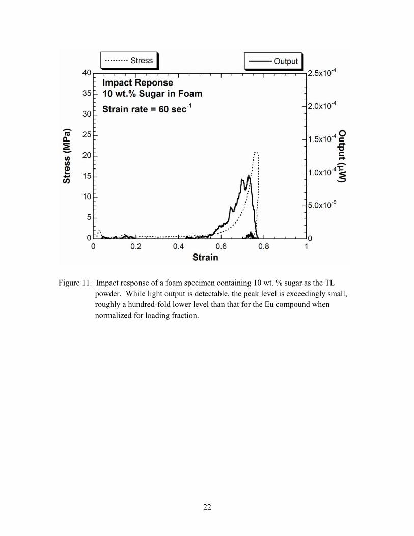
Figure 11. Impact response of a foam specimen containing 10 wt. % sugar as the TL
powder. While light output is detectable, the peak level is exceedingly small, roughly a hundred-fold lower level than that for the Eu compound when normalized for loading fraction.
22

IX. Distribution 1 MS 0888 01811 Jim Aubert 1 MS 0888 01811 Ed Russick 1 MS 9031 11600 Tim Evans 1 Attn: 9161 08726 Tony Chen 08721 John Hamilton 1 MS 9042 08727 Paul Spence 08728 Christopher Moen 08730 John Goldsmith 08731 Bill Replogle 1 MS 9405 08700 Jill Hruby 1 MS 9401 08702 Glen Kubiak 1 MS 9401 08729 Craig Henderson 1 MS 9402 08724 Chuck Cadden 5 MS 9403 08722 Paul Dentinger 1 MS 9403 08722 Linda Domeier 1 MS 9403 08722 Bill Even 1 MS 9403 08722 Pat Keifer 1 MS 9403 08722 James McElhanon 1 MS 9403 08722 Tim Shepodd 1 MS 9403 08722 Blake Simmons 1 MS 9403 08723 Jim Wang 5 MS 9403 08722 LeRoy Whinnery 1 MS 9404 08725 John Garcia 5 MS 9404 08725 Steve Goods 1 MS 9404 08725 Roger Watson 1 MS 0899 Technical Library, 9616 3 MS 9018 Central Technical Files, 8945-1 1 MS 9021 Classification Office, 8511/Technical Library, MS 0899, 9616
DOE/OSTI via URL
23

24
This page intentionally left blank