FLAMMABLE LIQUIDS, VAPORS, AND GASESftp.feq.ufu.br/Luis_Claudio/Segurança/Safety... · FLAMMABLE...
84
83 5 FLAMMABLE LIQUIDS, VAPORS, AND GASES 5-1. Ignition Hazards of Liquid Vapor and Mist 5-1.1. Flammable Liquid Liquids with closed-cup flash points less than 100°F have a recognized ability to form flammable vapor–air mixtures under ambient conditions and are commonly known as flammable liquids. While liquids with flash points ‡100°F usually require an elevated temperature to form flammable vapor–air mixtures and are sometimes known as combustible liquids, other effects such as flash point error, reduced ambient pressure, dispersion into fine drop- lets or some combination of these should be considered when using the reported flash point to assess flammability hazard. Some liquids with a low fire hazard, for example paints comprising mostly water, may be classed by NFPA 704 as combustible even though they can generate explosive vapor-air mixtures in closed containers at less than 100°F; the NFPA fire hazard rating can be as low as 1 which normally indicates a flash point ‡200°F. Similarly, some liquids with no measurable flash point may generate flammable vapor via degassing or slow decomposition in large containers, especially where the vapor space is small compared with the liquid volume. In such cases the vapor space may need flammability evaluation under actual use conditions. The use of a 100°F demarcation between flammable and combustible liquids is gradually being replaced by the UN/DOT 141°F (60.5°C) demarcation, which allows for elevated temperatures during transportation. The NFPA and DOT systems for flammable and combustible liquids can be found in the “Glos- sary” under “Class.” These systems both assume “round number” demarca- tions at 140°F and 200°F, although the 140°F breakpoints are not consistent. NFPA Class IIIA combustible liquids have flash points ‡140°F while DOT com- bustible liquids have flash points >141°F.
Transcript of FLAMMABLE LIQUIDS, VAPORS, AND GASESftp.feq.ufu.br/Luis_Claudio/Segurança/Safety... · FLAMMABLE...
83
5FLAMMABLE LIQUIDS, VAPORS,
AND GASES
5-1. Ignition Hazards of Liquid Vapor and Mist
5-1.1. Flammable Liquid
Liquids with closed-cup flash points less than 100°F have a recognized abilityto form flammable vapor–air mixtures under ambient conditions and arecommonly known as flammable liquids. While liquids with flash points³100°F usually require an elevated temperature to form flammable vapor–airmixtures and are sometimes known as combustible liquids, other effectssuch as flash point error, reduced ambient pressure, dispersion into fine drop-lets or some combination of these should be considered when using thereported flash point to assess flammability hazard. Some liquids with a lowfire hazard, for example paints comprising mostly water, may be classed byNFPA 704 as combustible even though they can generate explosive vapor-airmixtures in closed containers at less than 100°F; the NFPA fire hazard ratingcan be as low as 1 which normally indicates a flash point ³200°F. Similarly,some liquids with no measurable flash point may generate flammable vaporvia degassing or slow decomposition in large containers, especially wherethe vapor space is small compared with the liquid volume. In such cases thevapor space may need flammability evaluation under actual use conditions.The use of a 100°F demarcation between flammable and combustible liquidsis gradually being replaced by the UN/DOT 141°F (60.5°C) demarcation, whichallows for elevated temperatures during transportation. The NFPA and DOTsystems for flammable and combustible liquids can be found in the “Glos-sary” under “Class.” These systems both assume “round number” demarca-tions at 140°F and 200°F, although the 140°F breakpoints are not consistent.NFPA Class IIIA combustible liquids have flash points ³140°F while DOT com-bustible liquids have flash points >141°F.
5-1.1.1. Flash Point Test ErrorFlash point does not in general represent the minimum temperature atwhich a pool of liquid will form a flammable atmosphere. Closed cup testmethods involve downward flame propagation, which is more difficult thanupward propagation, and the region where the test flame is introduced isnormally fuel-lean relative to the liquid surface. Also, the volume of theclosed cup test apparatus is too small to allow flame propagation of certainflammable vapors such as halogenated organics. Limitations of the flashpoint test are discussed in the Appendix to ASTM E 502, where it states, “Ifprocess or handling conditions dictate the usage of a flammable material attemperatures ranging upward from 5–10°C below the closed cup flash point,then a flammable vapor might be present above the liquid, and the potentialhazard might be more precisely defined by determining such properties astemperature limit of flammability (Test Method E 1232) or flammable limitconcentrations (Test Method E 681), or both, at the contemplated condi-tions.” While closed-cup flash points are usually lower than open cup values,this is not always the case as noted in the Appendix to ASTM E 502.
5-1.1.2. Liquid Temperature ErrorThe surface temperature of stagnant liquid in a heated or uninsulated tankmay significantly exceed the bulk liquid temperature owing to heat transferfrom the unwetted upper walls. An uninsulated tank might be heated by sun-light to about 60°C. Since vapor–liquid equilibrium is established at thevapor–liquid interface, an excessive liquid surface temperature can result inan elevated vapor concentration relative to the calculated value based on bulkliquid temperature. Vapor in the tank may be flammable even if the bulk liquidtemperature is less than the reported flash point; an unrecognized hazardcould result if the vapor is assumed to be below the lower flammable limit(LFL). Conversely, even where the tank vapor space is clearly above the upperflammable limit (UFL), an ignitable mixture will always exist in the vicinity ofan open vent. Furthermore, vapor vented from large air-breathing field storagetanks may be at only 30–50% of theoretical saturation based on bulk liquidtemperature. Hence a tank explosion hazard might be overlooked if the entirevapor space is assumed to be above the UFL (5-1.2).
5-1.1.3. Ambient Pressure ErrorThe equilibrium vapor pressure above a confined liquid depends only ontemperature. The fraction of the total pressure exerted by vapor pressuredetermines the composition of the vapor–air mixture. Thus when the totalpressure is reduced, for example at high elevations or in vacuum trucks, thevapor concentration in air increases. Since flash points are reported at a
84 5. FLAMMABLE LIQUIDS, VAPORS, AND GASES
standard pressure of 760-mmHg an ambient pressure less than this valuedepresses the effective flash point. The observed flash point at pressure P(mmHg) can be estimated from the standard flash point (760 mmHg) usingan adaptation of the correction formula given in ASTM E 502
Observed flash point = standard flash point – N (760 – P) (5-1.1.3)
where constant N (0.03 for flash point in degrees Celsius and 0.06 for flashpoint in degrees Fahrenheit) should be considered only approximate.
5-1.1.4. Low Concentration Volatiles ErrorSmall concentrations of volatile components in a liquid mixture may accu-mulate in the vapor space of a container over time and appreciably reducethe flash point relative to the reported closed-cup value. This may be theresult of degassing, chemical reaction or other mechanism. An example isbitumen [162]. Similarly, if a tank truck is not cleaned between deliveries ofgasoline and a high flash point liquid such as kerosene or diesel oil, the mix-ture might generate a flammable atmosphere both in the truck tank and thereceiving tank. Contamination at the thousand ppm level may create haz-ards (5-1.4.3 and 5-2.5.4). Solids containing upward of about 0.2 wt% flam-mable solvent need to be evaluated for flammable vapor formation incontainers (6-1.3.2).
5-1.1.5. Safety Margin for Flash Point ApplicationIn view of the above adverse effects a safety factor should be applied whereflammability is assessed using flash point. For pure liquids in containers thevapor should be considered potentially flammable if the liquid temperatureis upward of at least 5°C below the reported flash point. For mixtures whosecomposition is less certain, such as petroleum mixtures, the safety factorshould be about 15°C relative to the flash point [55]. Where combinations ofadverse effects are identified the safety factors should be increased accord-ingly. A simple but very conservative approach is to assume that all liquidshaving a flash point £141°F may produce a flammable atmosphere undersome ambient conditions, even where no mist or froth production isinvolved. A more practical approach is to assume that liquids handled in airat least 5–15°C below their closed cup flash points will not present ignitionrisks unless
• they are handled in a manner that produces mist or froth,• they contain small concentrations of volatile material that is not pre-
served during flash point sampling and testing, or• they generate flammable gas via slow reactions.
5. FLAMMABLE LIQUIDS, VAPORS, AND GASES 85
5-1.2. Flammable Limits
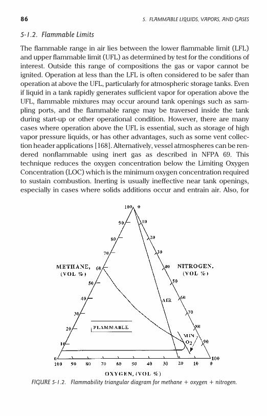
The flammable range in air lies between the lower flammable limit (LFL)and upper flammable limit (UFL) as determined by test for the conditions ofinterest. Outside this range of compositions the gas or vapor cannot beignited. Operation at less than the LFL is often considered to be safer thanoperation at above the UFL, particularly for atmospheric storage tanks. Evenif liquid in a tank rapidly generates sufficient vapor for operation above theUFL, flammable mixtures may occur around tank openings such as sam-pling ports, and the flammable range may be traversed inside the tankduring start-up or other operational condition. However, there are manycases where operation above the UFL is essential, such as storage of highvapor pressure liquids, or has other advantages, such as some vent collec-tion header applications [168]. Alternatively, vessel atmospheres can be ren-dered nonflammable using inert gas as described in NFPA 69. Thistechnique reduces the oxygen concentration below the Limiting OxygenConcentration (LOC) which is the minimum oxygen concentration requiredto sustain combustion. Inerting is usually ineffective near tank openings,especially in cases where solids additions occur and entrain air. Also, for
86 5. FLAMMABLE LIQUIDS, VAPORS, AND GASES
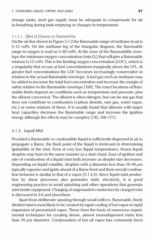
FIGURE 5-1.2. Flammability triangular diagram for methane + oxygen + nitrogen.
storage tanks, inert gas supply must be adequate to compensate for airin-breathing during tank emptying or changes in temperature.
5-1.2.1. Effect of Diluents on FlammabilityOn the air line shown in Figure 5-1.2 the flammable range of methane in air is5–15 vol%. On the methane leg of the triangular diagram, the flammablerange in oxygen is read as 5–60 vol%. At the nose of the flammability enve-lope the minimum oxygen concentration (min O2) that will give a flammablemixture is 12 vol%. This is the limiting oxygen concentration (LOC), which isa singularity that occurs at fuel concentrations marginally above the LFL. Atgreater fuel concentrations the LOC becomes increasingly conservative inrelation to the actual flammable envelope. A fuel gas such as methane maybe added to increase the total fuel concentration and increase the margin ofsafety relative to the flammable envelope [168]. The exact locations of flam-mable limits depend on conditions such as temperature and pressure, plusthe diluent concerned. The diluent is often nitrogen, but can be any gas thatdoes not contribute to combustion (carbon dioxide, rare gas, water vapor,etc.) or some mixture of these. It is usually found that diluents with largerheat capacities decrease the flammable range and increase the ignitionenergy although the effects may be complex [142, 168–171].
5-1.3. Liquid Mist
Provided a flammable or combustible liquid is sufficiently dispersed in air topropagate a flame, the flash point of the liquid is irrelevant in determiningignitability of the mist. Even at very low liquid temperatures, frozen liquiddroplets may burn in the same manner as a dust cloud. Ease of ignition andrate of combustion of a liquid mist both increase as droplet size decreases.Depending on liquid volatility, droplets with a diameter less than 10–40 mmtypically vaporize and ignite ahead of a flame front and their overall combus-tion behavior is similar to that of a vapor (5-1.4.4). Since liquid mist produc-tion by shear processes also generates static electricity, it is goodengineering practice to avoid splashing and other operations that generatemist inside equipment. Charging of ungrounded conductors by charged mistis discussed in 5-6 and elsewhere.
Apart from deliberate spraying through small orifices, flammable, finelydivided mist is most likely to be created by rapid cooling of hot vapor or rapidexpansion of pressurized vapor. These form the basis of numerous experi-mental techniques for creating dense, almost monodispersed mists lessthan 10 mm diameter. Condensation of hot oil vapor has commonly been
5. FLAMMABLE LIQUIDS, VAPORS, AND GASES 87
used to produce ~0.6-mm mist found optimum for smoke screens [180].Depending on cloud thickness, droplet size, and illumination, mists typicallybecome optically dense at much less than their LFLs.
During processes such as splashing, the production of easily ignitedmists of combustible liquids such as diesel oil is unlikely unless a froth layeris produced. This is because the liquid concentration in the mist will nor-mally be less than the LFL. The LFL varies with the liquid and decreases asdroplet size is increased. A typical LFL range for an oil is about 50 mg/L at5 mm decreasing to 10 mg/L above 80 mm [179]. These concentrations areoptically dense, especially for finer, more easily ignitable mists. However,there is adequate liquid in a froth layer to create a flammable mist of finedroplets (5-1.3.1). If ignition occurs, the flame can propagate into coarsermist above the froth layer. Subsequent combustion may involve all of thesuspended mist in the container, augmented by droplets and vapor derivedfrom any incoming liquid stream.
5-1.3.1. Froth or FoamAeration of a liquid, for example via splashing, forms gas bubbles whichincrease the liquid interfacial area at which charging occurs. In addition toincreasing the charge generation rate, aeration may create a relatively longlasting froth which in turn is a source of very fine mist as it bursts. Burst rate isgreatly increased locally by a static spark and the froth is completely dis-rupted ahead of any flame. Froths, like mists, can be ignited at less than theflash point of the liquid. Another feature of froths (see below) is that thetwo-phase system has a volume conductivity less than that of the continuousliquid phase, so may both accumulate a surface charge and hinder chargedissipation from any isolated conductive object in the froth layer. Such con-ductive objects are not restricted to obvious items such as soda cans. Otherpossibilities include metal debris buoyed up from the bottom of the tank, iceor hydrates derived from the hose or tank surfaces and isolated patches ofliquid product or water.
If a froth is produced by degassing following a sudden decrease in pres-sure, previously dissolved gases will determine the combustion behavior ofthe froth. Owing to the very high solubility of light aliphatic hydrocarbons inmost oils the appearance of flammable gas is expected in such cases.Oxygen is typically more soluble than nitrogen (Table 3-8.1.2), so the frothcan additionally be enriched with oxygen during degassing.
In 1965 a powerful explosion and ensuing fire occurred while gravityloading kerosene to a barge under conditions producing excessive bubbling,foaming and turbulence [111]. The explosion occurred at much less than the
88 5. FLAMMABLE LIQUIDS, VAPORS, AND GASES
liquid flash point of 110–130°F and the only credible mechanism was staticignition of mist inside the tank compartment. Kerosene is a nonconductiveliquid. Since it was established that free water plus a large quantity of airflowed into the barge tank from the 10 in. supply line, charge accumulationwas predictable (5-3.1.1). However, liquids do not need to be noncon-ductive to accumulate charge. In December 1987, semiconductive butylacrylate liquid with a flash point of 49°C (120°F) ignited in a properlygrounded tank car at about 15°C [30]. The ester was introduced at highvelocity via a thrust neutralizer comprising four-way horizontal flow diver-sion at the foot of the filling lance. Flow rate was 1450 gpm through 6-in. pipefollowed by a partly inserted 4-in. dip pipe. When an account of the incidentwas published it was believed that flammable vapor had been present dueto a previous lading of methyl methacrylate [30]. However, in January 1989,an almost identical fire occurred in a dedicated butyl acrylate tank car, sug-gesting that both incidents were due to ignition of liquid mist at well belowthe liquid flash point. A possible explanation for both incidents involves highcharging due to shear in the thrust neutralizer, production of a liquid froth,and static discharge from charged liquid or other material supported by thefroth layer. While the conductivity of the ester involved is typically about3000 pS/m the effective conductivity of a froth layer might be 1–2 orders ofmagnitude less [UCC unpublished]. The company involved subsequentlychanged to 105J cars with fixed dip pipes.
If froth is produced by decomposition of an oxidizing agent such ashydrogen peroxide, the oxygen-enriched froth may be flammable and burnrapidly even in a completely inerted vessel (5-9.6.1).
5-1.4. Minimum Ignition Energy (MIE)
While flammability exists throughout the flammable range the energyrequired to ignite fuel–air mixtures varies by orders of magnitude as thecomposition is changed. At the flammable limits the ignition energy by defi-nition increases toward infinity. Flammable limit measurement typicallyinvolves electrical energies of the order 10 J. A minimum value known as thelowest minimum ignition energy (LMIE) or simply as the minimum ignitionenergy (MIE) is exhibited approximately half-way between the flammablelimits [8]. The LMIE for most flammable vapors in air is between 0.1 and 1 mJ(Appendix B). Since the energy available from most electrostatic dischargesis small (typically less than 10 mJ) relative to the energy used to establishflammable limits, the probability of ignition is usually strongly related to theprobability of generating the most easily ignitable mixture. Liquids close to
5. FLAMMABLE LIQUIDS, VAPORS, AND GASES 89
their flash points, or to their flammable limits, are generally not susceptibleto weak static discharges. Brush discharges are particularly ineffective closeto the UFL (Figure 2-6.2.1). The MIE is increased by a reduction in the oxygenconcentration relative to air, for example by partial nitrogen inerting. How-ever, this effect may not be pronounced until the oxygen concentration inthe oxidant is decreased below about 16 vol%. This is based on pro-pane–air–nitrogen mixture MIE data in [57]; in order to increase the MIE ofpropane from 0.25 to 1.0 mJ, an additional 23 vol% nitrogen needed to beadded to air, corresponding to an oxygen reduction from about 21 to 16 vol%in the oxidant mixture.
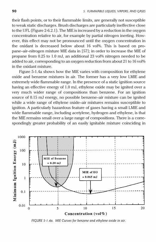
Figure 5-1.4a shows how the MIE varies with composition for ethyleneoxide and benzene mixtures in air. The former has a very low LMIE andextremely wide flammable range. In the presence of a static ignition sourcehaving an effective energy of 1.0 mJ, ethylene oxide may be ignited over avery much wider range of compositions than benzene. For an ignitionsource of 0.15 mJ energy, no possible benzene–air mixture can be ignitedwhile a wide range of ethylene oxide–air mixtures remains susceptible toignition. A particularly hazardous feature of gases having a small LMIE andwide flammable range, including acetylene, hydrogen and ethylene, is thatthe MIE remains small over a large range of compositions. There is a corre-spondingly greater probability of an easily ignitable mixture coinciding in
90 5. FLAMMABLE LIQUIDS, VAPORS, AND GASES
FIGURE 5-1.4a. MIE Curves for benzene and ethylene oxide in air.
time and space with a static ignition source. Appendix B provides a tabula-tion of LMIE values for a number of flammable gases and vapors.
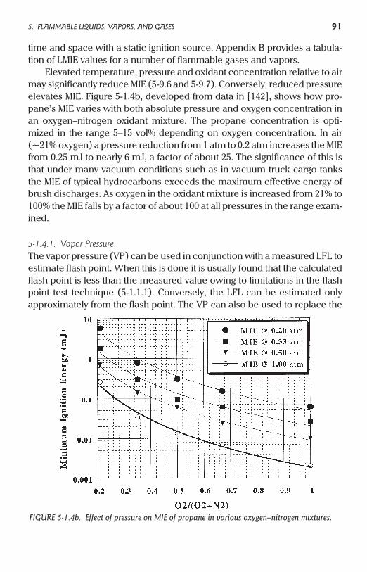
Elevated temperature, pressure and oxidant concentration relative to airmay significantly reduce MIE (5-9.6 and 5-9.7). Conversely, reduced pressureelevates MIE. Figure 5-1.4b, developed from data in [142], shows how pro-pane’s MIE varies with both absolute pressure and oxygen concentration inan oxygen–nitrogen oxidant mixture. The propane concentration is opti-mized in the range 5–15 vol% depending on oxygen concentration. In air(~21% oxygen) a pressure reduction from 1 atm to 0.2 atm increases the MIEfrom 0.25 mJ to nearly 6 mJ, a factor of about 25. The significance of this isthat under many vacuum conditions such as in vacuum truck cargo tanksthe MIE of typical hydrocarbons exceeds the maximum effective energy ofbrush discharges. As oxygen in the oxidant mixture is increased from 21% to100% the MIE falls by a factor of about 100 at all pressures in the range exam-ined.
5-1.4.1. Vapor PressureThe vapor pressure (VP) can be used in conjunction with a measured LFL toestimate flash point. When this is done it is usually found that the calculatedflash point is less than the measured value owing to limitations in the flashpoint test technique (5-1.1.1). Conversely, the LFL can be estimated onlyapproximately from the flash point. The VP can also be used to replace the
5. FLAMMABLE LIQUIDS, VAPORS, AND GASES 91
FIGURE 5-1.4b. Effect of pressure on MIE of propane in various oxygen–nitrogen mixtures.
concentration axis in Figure 5-1.4a with the corresponding temperaturesrequired to generate these concentrations. In this way one can determinethe equilibrium liquid temperature at which vapor ignition is most probable,corresponding to generation of the LMIE composition (5-1.4). For manyaliphatic and aromatic hydrocarbons this composition is approximatelyequal to the average of the LFL and UFL, although this rule does not gener-ally apply to other chemicals [8]. For vapor–liquid equilibrium, benzene gen-erates its LMIE vapor-air mixture at about 7°C and toluene at about 26°C(Table 5-1.4.1). For operations conducted close to room temperature, tolu-ene is more prone to ignition from low energy static discharges than ben-zene [8]. This is because benzene’s equilibrium vapor concentrationexceeds the UFL at temperatures above about 16°C. However, at colder tem-peratures of 0–5°C benzene is more prone to ignition, since toluene vapor isclose to or less than its LFL. Included in Table 5-1.4.1 is an example of aVM&P naphtha (vergaellungsmittel petrolether). Since VM&P is primarily amixture of various paraffins and naphthenes, plus minor aromatics such asxylene, various formulations can be readily characterized only by theirclosed-cup flash points (9°C in this case) and flammable limits (1–6% in thiscase). However, in the context of Table 5-1.4.1 it can be seen that thisnonconductive liquid should be prone to static ignition at ambient tempera-ture and pressure. This inference is supported by the incidence of tank truckloading fires. Petroleum naphthas having elevated flash points compared
92 5. FLAMMABLE LIQUIDS, VAPORS, AND GASES
TABLE 5-1.4.1 Approximate Vapor–Liquid Equilibrium Temperatures for LFL, LMIE,and UFL Vapor Concentrations at Atmospheric Pressure
Liquid LFL (%) LFL (°C) LMIE (%) LMIE (°C) UFL (%) UFL (°C)
Diethyl ether 1.9 –46 5.1 –28 36.0 9
n-Hexane 1.1 –25 3.8 –5 7.5 5
Cyclohexane 1.3 –18 3.8 4 8.0 15
Benzene 1.3 –12 4.7 7 7.8 16
n-Heptane 1.0 –4 3.4 14 6.7 26
Methanol 6.0 8 14.7 25 36.0 42
Toluene 1.1 4 4.1 26 7.1 37
(VM&P naphtha) ~1 ~9 3.5–4.0 (est) 20–30 (est) ~6 Unknown
Ethyl benzene 0.8 15 3.8 (est) 48 6.7 58
Styrene, xylene(s) 0.9–1.1 23–28 3.8 (est) ~50 6.7–7.0 60–65
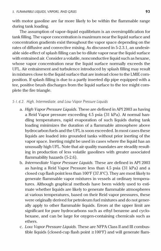
with motor gasoline are far more likely to be within the flammable rangeduring tank loading.
The assumption of vapor–liquid equilibrium is an oversimplification fortank filling. The vapor concentration is maximum near the liquid surface andconcentration gradients exist throughout the vapor space depending on therates of diffusive and convective mixing. As discussed in 5-2.3.1, an undesir-able side-effect of splash filling can be to dilute vapor near the liquid surfacewith entrained air. Consider a volatile, nonconductive liquid such as hexane,whose vapor concentration near the liquid surface normally exceeds theUFL. Air entrainment and turbulence introduced by splash filling may resultin mixtures close to the liquid surface that are instead close to the LMIE com-position. If splash filling is due to a partly inserted dip pipe equipped with atee, positive brush discharges from the liquid surface to the tee might com-plete the fire triangle.
5-1.4.2. High, Intermediate, and Low Vapor Pressure Liquids
a. High Vapor Pressure Liquids. These are defined in API 2003 as havinga Reid Vapor pressure exceeding 4.5 psia (31 kPa). At normal han-dling temperatures, rapid evaporation of such liquids during tankloading minimizes the duration of a flammable atmosphere abovehydrocarbon fuels and the UFL is soon exceeded. In most cases theseliquids are loaded into grounded tanks without prior inerting of thevapor space. Inerting might be used in cases where the liquid has anunusually high UFL. Note that air quality mandates are steadily result-ing in production of less volatile gasolines with greater associatedflammability hazards (5-2.6).
b. Intermediate Vapor Pressure Liquids. These are defined in API 2003as having a Reid Vapor Pressure less than 4.5 psia (31 kPa) and aclosed cup flash point less than 100°F (37.8°C). They are most likely togenerate flammable vapor mixtures in vessels at ordinary tempera-tures. Although graphical methods have been widely used to esti-mate whether liquids are likely to generate flammable atmospheresat various temperatures, based on their Reid vapor pressures, thesewere originally derived for petroleum fuel mixtures and do not gener-ally apply to other flammable liquids. Errors at the upper limit aresignificant for pure hydrocarbons such as ethyl benzene and cyclo-hexane, and can be large for oxygen-containing chemicals such asethers.
c. Low Vapor Pressure Liquids. These are NFPA Class II and III combus-tible liquids (closed-cup flash point ³100°F) and will generate flam-
5. FLAMMABLE LIQUIDS, VAPORS, AND GASES 93
mable atmospheres only if handled at elevated temperature,suspended as a mist or subject to slow vapor evolution. However,static electricity generated during handling may ignite flammablevapor present from previous operations (5-1.4.3).
5-1.4.3. Switch LoadingThis is the practice of loading liquid, typically a low vapor pressure liquid,into a vessel containing a flammable or fuel-rich atmosphere from a previ-ous use. A flammable atmosphere may form during loading or may persistthroughout loading. The worst case is for the atmosphere to remain at itsmost easily ignitable composition throughout loading, which might occur ifthere is negligible scrubbing of the vapor by the liquid being loaded (3-8.1.2).The worst case situation is similar to loading a pure liquid such as toluenewhose vapor pressure at normal loading temperatures frequently results inan easily ignitable composition throughout loading. Thus, switch loadingmay be more hazardous than loading an intermediate vapor pressure liquidwhose equilibrium vapor composition either traverses the flammable rangeor does not attain the most easily ignitable composition during loading.Switch loading has been the cause of numerous fires. Since the operation isno more hazardous than loading a pure liquid such as toluene having thesame electrical properties, the root cause of these fires must be either failureto follow procedures appropriate for flammable liquid loading (such as limi-tation of flow rates) or unusually long relaxation times associated with thelow vapor pressure liquid. This is the case with viscous nonconductive liq-uids such as some lubricating oils, which may require inerted conditions forswitch loading (5-2.5.4).
Note: Section A-5-6.3 of the 1996 edition of NFPA 30 (reiterated in NFPA 385)contains erroneous information about switch loading.
When a tank is emptied of Class I liquid, there is left a mixture of vapor andair, which can be, and often is, within the flammable range. When such atank is refilled with a Class I liquid, any charge that reaches the tank shellwill be bled off by the required bond wire. Also, there will be no flammablemixture at the surface of the rising oil level because the Class I liquid pro-duces at its surface a mixture too rich to be ignitable.
Toluene is a Class I liquid (see “Glossary”). Not only is it unlikely to produce arich mixture at its surface at ambient temperature, but the mixture producedis often close to its most easily ignitable composition throughout loading.This common misconception about switch loading is based on the behaviorof gasoline and does not apply to Class I liquids in general. It is impossible forswitch loading to result in more easily ignitable mixtures than occur when
94 5. FLAMMABLE LIQUIDS, VAPORS, AND GASES
loading a pure liquid such as toluene at a temperature corresponding to itsmost easily ignitable vapor composition (5-1.4.1). This oversight in NFPA 30may be traced to its traditional and primary application to storage of hydro-carbon fuels such as gasoline.
NFPA 30 also fails to recommend flow rate restrictions except a slowstart until the downspout is submerged. Section 5-4 of this book provides forrestricted flow rates throughout filling; this should be applied wherevercharge accumulation is possible due to low liquid conductivity and whereflammable mixtures involving gas, mist or froth may be formed.
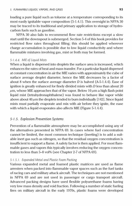
5-1.4.4. MIE of Liquid MistsWhen a liquid is dispersed into droplets the surface area is increased, whichenhances the rates of heat and mass transfer. For a particular liquid dispersedat constant concentration in air the MIE varies with approximately the cube ofsurface average droplet diameter, hence the MIE decreases by a factor ofabout 8 when the surface average diameter D is halved (A-5-1.4.4). Ease ofignition is greatly enhanced for finely divided mists with D less than about 20mm, whose MIE approaches that of the vapor. Below 10 mm a high flash pointliquid mist (tetrahydronaphthalene) was found to behave like vapor whileabove about 40 mm the droplets tended to burn individually [142]. Since liquidmists must partially evaporate and mix with air before they ignite, the easewith which a liquid evaporates also affects MIE (Figure 5-1.4.4).
5-1.5. Explosion Prevention Systems
Prevention of a flammable atmosphere may be accomplished using any ofthe alternatives presented in NFPA 69. In cases where fuel concentrationcannot be limited, the most common technique (inerting) is to add a suit-able inert gas such as nitrogen, so that the residual oxygen concentration isinsufficient to support a flame. A safety factor is then applied. For most flam-mable gases and vapors this typically involves reducing the oxygen concen-tration to less than 5–8 vol% (see Chapter 2-7 of NFPA 69).
5-1.5.1. Expanded Metal and Plastic Foam PackingVarious expanded metal and foamed plastic matrices are used as flamearresters when packed into flammable vapor spaces such as the fuel tanksof racing cars and military attack aircraft. The techniques are not mentionedin NFPA 69 and are not used in passenger or cargo transport aircraft.Advanced packing designs have used flexible polyurethane foams havingvery low mass density and void fraction. Following a number of static fuelingfires on military aircraft in the early 1970s, plastic foams were developed
5. FLAMMABLE LIQUIDS, VAPORS, AND GASES 95
having antistatic properties and various nozzle designs (such as piccolos)were investigated to minimize charging between the plastic foams and the jetfuels (notably JP-4) involved. Additionally, the fuel conductivity was increasedto at least 200–600 pS/m. Information on this topic can be found in [112–118],of which the best introduction is [118]. There are probably valid applicationsin the CPI for passive protection systems involving packing and it might beargued that equipment such as packed columns already has this protection tosome degree. However, packing that was not specifically designed andinstalled to prevent flame propagation at the conditions involved cannot beexpected to act as a flame arrester, even though the extent of flame propaga-tion inside the packed equipment is greatly reduced. Practical considerationsfor plastic foams include compatibility of liquids with the plastic foam, generalquality concerns, and the cleaning, inspection and maintenance difficultiesthat would be introduced.
5-2. Generation and Relaxation (Loss) of Charge inLiquid Systems
5-2.1. Charge Generation
Ionic species present in liquids undergo adsorption at interfaces such thatpredominantly one sign of charge is more strongly bound at the contactedsurface than the other. This results in a bound layer close to the surface far-ther from which is a diffuse layer having a net countercharge. This two-layer
96 5. FLAMMABLE LIQUIDS, VAPORS, AND GASES
FIGURE 5-1.4.4. Schematic effect of droplet diameter on MIE of typical petroleum products.
system having opposite net charges is referred to as an electrical doublelayer. For conductive liquids such as water the diffuse layer is only a few mol-ecules thick but for nonconductive liquids such as light petroleum distillatesthe layer may be many millimeters thick. Processes producing surface shearseparate the weakly held diffuse layer from the bound layer. For example,during flow of a liquid hydrocarbon through a pipe the diffuse layer is carrieddownstream and may result in accumulation of the net charge in a receivingtank. Charge separation occurs whenever shear effects occur at an interfaceso additional examples include splashing, spraying, and stirring. Where alarge contact surface is available per unit volume the rate of charge genera-tion is increased. Examples are filtration and agitation of two-phase systemssuch as liquid–gas, water–oil or powder–solvent suspensions.
5-2.2. Charge Density
The net charge (Coulombs, C) in a specified volume of liquid (cubic meters,m3) gives charge per unit volume or charge density (C/m3). Since flow in apipe can be described by a flow velocity, and current is defined as the flow ofcharge per unit time, the flow of net charge carried along the pipe by flowingliquid represents a charging current or “streaming” current
Charging current (C/s or Amperes) = Volume flow rate (m3/s)´ Charge density (C/m3) (5-2.2)
5-2.3. Factors Influencing Charge Generation
See 2-1.1 and 2-3.1. The mechanism of charge generation is highly complex.For flow of liquid in pipes it can be shown that the charging current dependson liquid dielectric properties (electrical conductivity and dielectric con-stant), viscosity, and flow characteristics, involving factors such as flowvelocity, pipe diameter and surface roughness. For equal flow characteris-tics, the electrical conductivity is the dominant factor affecting charging. Thisis most pronounced for nonconductive liquids (k <102 pS/m) since the con-ductivity of such liquids may vary by orders of magnitude depending on theconcentration of trace contaminants. Trace contaminants have negligibleeffect on liquid dielectric constant and viscosity but have a dominant effecton conductivity. Owing to their much greater intrinsic conductivities, tracecontaminants have increasingly less effect on semiconductive (100 < k
<104 pS/m) and conductive (k > 104 pS/m) liquids. In many systems such aslong, grounded metal pipes it is found that the charge density attains a steadystate at which the rate of charge generation is balanced by the rate of chargerelaxation back to ground.
5. FLAMMABLE LIQUIDS, VAPORS, AND GASES 97
5-2.3.1. Splash FillingThis practice has been blamed for numerous fires and explosions, althoughoften for the wrong reasons. It is frequently stated that static is generatedwhen a liquid stream falls through the air and breaks into droplets. In prac-tice this is a minor hazard when filling tanks, even where the liquid is non-conductive. Charge generated by stream break-up is almost entirelycollected in the continuous liquid phase with negligible net charge accumu-lation. This has been verified by a large scale study which concluded“Splashing does not itself generate significant amounts of charge” [221].Although charged mist forms, it has a very small charge density comparedwith the continuous phase and is typically neglected in tank filling models.The hazards of splash-filling are principally related to effects other thanbreak-up of the incoming stream. These include the absence of electric fieldreduction by a metal dip pipe and the ability to accumulate excessive chargedensities at the liquid surface via stratification. The static hazards of chargedmist are normally significant only where operations such as sampling andgauging introduce ungrounded components into the tank. To allow dissipa-tion of charged mist prior to gauging a “wait time” may be needed (5-5.2).
Splash filling may also affect flammability. Froth and mist created bysplashing may be ignited at much less than the flash point of the bulk liquid(5-1.3.1). An opposite and previously unrecognized effect of splash filling isthe associated dilution of vapor near the liquid surface via air entrainmentand turbulence (5-1.4.1). When a tank is filled with a volatile liquid whoseequilibrium vapor concentration exceeds the UFL, a large fraction of thevapor space remains flammable until sufficient evaporation has taken place.However, in the absence of turbulent mixing the UFL is very rapidlyexceeded close to the evaporating liquid surface. Since ignition via brushdischarges typically occurs within 10 cm of the surface, air dilution maycreate an ignition hazard above liquids that otherwise would quickly gener-ate local vapor concentrations close to or above their UFLs. The probabilityof ignition of volatile liquids such as naphtha may therefore be increased bysplash filling as opposed to bottom filling. The effect of vapor concentrationon the frequency of ignition by brush discharges is discussed in 2-6.2.1.
5-2.4. Charge Relaxation
See 2-3. Provided k is above ~2 pS/m, charged hydrocarbons such as gaso-line contained within grounded, conductive containers or pipe lose chargeto ground at a first order (Ohmic) rate governed by the following equations
t = er e0/k (2-3.2)
98 5. FLAMMABLE LIQUIDS, VAPORS, AND GASES
dQ/dt= –Q/t (2-3.6)
Qt = Q0 exp(–t/t) (2-3.7)
The relaxation time (t) is a parameter governing the rate at whichcharge is lost from a liquid, accounting for both its electrical conductivity (k)and permittivity (er e0). The integrated rate equation (2-3.7) shows that 36.7%of the initial charge remains after one relaxation time (when t = t), 13.5%remains after two relaxation times, 5.0% remains after three relaxation timesand 0.67% remains after five relaxation times. By providing three or morerelaxation times between filling a tank and carrying out tank sampling orother hazardous operation, the charge introduced by the filling process willusually have decayed 95% or more. As discussed later, certain exceptions toideal behavior can occur.
Case 1. Ungrounded Conductive Tank. When an ungrounded tank isfilled, the potential on the tank at any time t is proportional to the total accu-mulated charge (A-4-1.3)
Vt= ICRL1 – exp(–t/RLC) (5-2.4.1)
where IC = charging current (A), RL = leakage resistance from tank toground (W), and C = tank capacitance (F).
The tank potential is independent of the relaxation time of the liquid,since the tank acts as a Faraday pail (3-5.1.2).
Case 2. Grounded Conductive Tank. It is sometimes possible to accu-mulate hazardous potentials on nonconductive liquid surfaces in groundedtanks. Since the ignition hazard depends on surface potential, which isdirectly proportional to the charge density in the tank, the relaxation time ofthe liquid is a critical parameter when modeling the variation of surfacepotential with time. It is typically assumed that the liquid is uniformlycharged and in contact with grounded metal, even at the free surface. It wasshown in 2-3 that the rate of charge loss from charged liquid is proportionalto the charge remaining but is independent of the shape of grounded bound-ary. A charge balance on the liquid volume can therefore be written
dQ/dt = IC – Q/t (5-2.4.2)
For constant charging current, and boundary conditions Q = 0 whent = 0, the total charge is
Qt = ICt 1– exp(–t/t) (5-2.4.3)
5. FLAMMABLE LIQUIDS, VAPORS, AND GASES 99
This equation was originally given for liquid flowing through a large, fulltank such that the liquid level was in contact with grounded walls over theentire boundary and the current loss via flow out of the tank could beneglected [55]. If both sides of Eq. (5-2.4.3) are divided by the volume filledat time t, one arrives at the time-dependent equation for charge density QV(t)typically used in tank filling models [22]
QV(t) = ( ICt / Vt)1 – exp (–t/t) (5-2.4.4)
where Vt = volume (m3) filled at time t (s).The assumption of constant charge density implies a mixing time that is
small compared with the relaxation time. In reality the inlet jet always con-tains a greater charge density than the surrounding liquid in the tank and thefree surface always contains excess charge. Also, charged liquid enteringtanks with large L/D ratios such as tank trucks and rail cars is unlikely to bewell-mixed at the ends. Conditions such as splash filling or partly inserted dippipes during overhead loading, and undeflected jet penetration to the surfaceduring bottom loading, can cause excessive accumulation of charge at thefree surface resulting in elevated surface potentials and possibly ignition.
5-2.4.1. Hyperbolic RelaxationIf all liquids lost charge according to the Ohmic equations in 5-2.4, those withvery low conductivities would have relaxation times of hours. However inthe 1960s, Bustin showed that nonviscous petroleum distillates with conduc-tivities less than about 2 pS/m relax charge much faster than predicted usingthe Ohmic equations [24]. Later analysis of Bustin’s model showed that thetime taken for high charge densities (100–5000 mC/m3) to decrease to safevalues (<20–30 mC/m3) is roughly independent of initial charge density [9].The charge dissipation time is approximately 90 s for oils with dielectric con-stant of 2 and 180 s for chemicals with a dielectric constant of 4 (A-5-2.4.1).Where liquid conductivities are less than about 2 pS/m, filters should ideallybe placed at least 100 s residence time upstream (5-2.4.2). In Appendix B,any nonconductive liquid whose typical conductivity is less than 2 pS/m isassigned a nominal 100 s dissipation time rather than a relaxation time. Forshort filling times, such as drumming, this behavior is comparable to a that ofan Ohmic liquid whose conductivity is 0.5 pS/m [8].
The hyperbolic relaxation equation (A-5-2.4.1a) contains charge carriermobility as a variable, which should be sensitive to oil viscosity. This is foundto be the case for some viscous nonconductive liquids. These have muchslower rates of charge dissipation equivalent to an Ohmic liquid whose con-ductivity is 0.02 pS/m (5-2.5.4).
100 5. FLAMMABLE LIQUIDS, VAPORS, AND GASES
There are no available data to establish whether nonconductive, low vis-cosity chemical products such as ethyl ether similarly display hyperbolicrelaxation below about 2 pS/m, or even whether this phenomenon is a prac-tical reality for such liquids. Should Ohmic relaxation behavior continue tomuch less than 0.5 pS/m the risk of static accumulation would be enhancedcompared with petroleum distillates.
5-2.4.2. Residence Time RequirementsWith reference to Figure 5-3.5, a relaxation volume should be providedbetween a charge generator such as a microfilter and a tank so that the resi-dence time is sufficient for charge to relax to safe levels. As discussed in 5-3.5and A-5-2.4.1, the residence time for nonconductive liquids that relax chargeOhmically should normally be three relaxation times or a default value of30 s. This criterion is often applied to all nonconductive liquids. In principlehowever, liquids with conductivities less than 2 pS/m that relax chargehyperbolically require about 100 seconds of residence time to achieve anequivalent reduction in charge density. Where practical, 100 s of residencetime should therefore be provided for liquids whose conductivity is typicallyless than 2 pS/m. An exception is viscous nonconductive liquids, whoserequired residence time may be impractically long (5-2.5.4). Unless antista-tic additives (5-2.6) can be used, inerting may be necessary if flammableatmospheres are present, for example, if switch loading is carried out.
5-2.5. Classification of Liquids based on Conductivity
The conductivities of flammable and combustible liquids vary from about10–4 pS/m to 1010 pS/m, that is, by about 14 orders of magnitude. Dielectricconstants usually vary over 1–2 orders of magnitude in the range 2–40; thehigher values are generally exhibited by polar molecules which also havehigher conductivities. Since relaxation behavior is primarily governed byconductivity this property can be used to assign any of three group classifica-tions conductive, semiconductive, and nonconductive. These are useful inclassifying the static dissipative characteristics of liquids for different charg-ing situations. While the rate of charge relaxation generally increases withincreased conductivity, the rate of charge generation such as during flowthrough pipes and filters often maximizes at the low end of the semi-conductive range (about 100 pS/m).
Since conductivity is highly sensitive to sample purity and temperature,group demarcations can be given only to within an order of magnitude. Itshould always be considered that conductivity under practical conditions
5. FLAMMABLE LIQUIDS, VAPORS, AND GASES 101
might be less than measured in the laboratory. Appendix B contains a listingof conductivities and relaxation times for different liquids. ASTM test meth-ods are discussed in 3-5.5.
5-2.5.1. Conductive LiquidsLiquids having conductivities greater than 104 pS/m, such as acetone, areconsidered conductive. Their relaxation times are typically less than about1 ms and for this reason they tend not to accumulate charge except wherehandling conditions isolate them from ground. These conditions includecomplete isolation in the form of a droplet suspension in air, partial isolationby suspension in another liquid, and containment in plastic or other highlyresistive container. A separated, nonconductive second phase in the form ofa froth (5-1.3.1) or skim layer (5-4.1.5) may isolate supported patches ofcharged liquid. Conductive liquids are most prone to induction charging byplastic containers and are sufficiently conductive to lose much of theinduced charge in the form of a spark.
5-2.5.2. Semiconductive LiquidsLiquids having conductivities between 102 pS/m and 104 pS/m such as butylacetate are considered semiconductive. Their relaxation times are usually inthe range 2–500 ms. For this reason they tend not to accumulate chargeexcept where charging rates are high and/or grounding is impeded, such asflow through rubber hose or end-of-line polishing filters, or where they areeffectively isolated from ground (5-2.5.1), or where they are partially isolatedby an underlying froth layer (5-1.3.1). Spark discharges may be possible fromthe more conductive of these liquids.
5-2.5.3. Nonconductive LiquidsLiquids having conductivities less than 102 pS/m such as purified toluene,diethyl ether and most low-sulfur diesel oils are nonconductive. Their relax-ation times are generally above 180 ms and often greater than 1 s. Their dielec-tric constants are typically 2–6 and they are highly susceptible to conductivityvariation due to trace contamination. In many cases, nonconductive liquidshave negligible intrinsic conductivity and conduction is due principally to con-taminants. For example, although commercial n-heptane typically has a con-ductivity of about 1 pS/m or more, after passing the liquid through silica gel toremove impurities its measured conductivity is less than 0.03 pS/m. Thisbehavior is used to establish zero for conductivity testing according to ASTM D3114. It follows that the conductivity of such liquids is extrinsic and may bedrastically reduced by processes such as distillation. Nonconductive liquidsare most prone to accumulate static and in some cases may generate haz-ardous potentials in grounded metallic containers.
102 5. FLAMMABLE LIQUIDS, VAPORS, AND GASES
For many years the petroleum industry has defined nonconductive liquidsas having conductivities less than 50 pS/m. A higher value of 100 pS/m is usedhere to address the higher dielectric constants of certain flammable chemi-cals in relation to petroleum products. For example the dielectric constant ofethyl ether is 4.6 versus 2.3 for benzene; from Eq. (2-3.2), ethyl ether thereforehas the same relaxation time at a conductivity of 100 pS/m as benzene at aconductivity of 50 pS/m. It is the relaxation time, not the conductivity alone,that determines the rate of loss of charge; hence the same logic that makes 50pS/m appropriate for identifying nonconductive hydrocarbons makes 100pS/m appropriate for identifying nonconductive chemical products.
Corona and brush discharges are observed from charged nonconduc-tive liquids rather than sparks. Since only partial discharge is possible, induc-tion charging from charged plastic containers is not a significant hazard.Relaxation (or dissipation) times are typically less than 100 s although cer-tain viscous nonconductive liquids with viscosity above 30–100 cS may dis-play longer relaxation times of the order 1000 s (5-2.5.4). In Appendix B, lowviscosity liquids with very low conductivity are considered to display anonohmic dissipation time of 100 s. This is to address the observation that asconductivity is reduced to less than about 2 pS/m, the rate of charge relax-ation is governed by a hyperbolic rather than Ohmic law (5-2.4.1). Slow set-tling of suspended material in tanks may increase the effective relaxationtime by generating a settling potential (5-4.1.2).
5-2.5.4. Viscous Nonconductive LiquidsSome liquids having a kinematic viscosity above 30–100 cS can have veryslow rates of charge dissipation, equivalent to a conductivity of about 0.02pS/m and a relaxation time of about 1000 s. Up to 5000 s may be needed todissipate charge. Filtration charging both in microfilters and strainers is typi-cally greater than for nonviscous liquids. For viscous oils through 10-mm fil-ters, charge densities up to 5000 µC/m3 are common while values this highare uncommon for nonviscous oils, even in finer filters. Unusually large con-centrations of antistatic additive may be required to render the liquids semi-conductive. Since safe charge dissipation times may be several thousandseconds, it might be impractical to provide adequate residence time andinerting should be considered where flammable vapor is present. Fuel oils,crude oils and lubricating oils containing detergent additives typically havehigh conductivities and do not pose this hazard. Conversely, base lubricatingoils, turbine fuels and transformer oils not containing additives can have vis-cosities upward of about 100 cS and conductivities of the order 0.02 pS/m[189]. Viscous silicon-based oils might have similar properties.
5. FLAMMABLE LIQUIDS, VAPORS, AND GASES 103
On February 11, 1999 a 375-m3 atmospheric tank was filled with luboilproduct from a barge. The viscous product (3000 cS at 20°C) had a flashpoint of 194°C and was trace heated to 90°C to facilitate handling. Follow-ing transfer, the line was blown down using compressed air at which pointignition occurred and the tank roof was blown off, landing on the groundbeside the tank. There were no injuries or spills and the fire rapidly extin-guished itself. It was found that the oil contained an unexpected 0.3 wt%hexane impurity which boiled off and formed a flammable mixture in thetank head space. It is predictable that static was generated during highvelocity two-phase flow in the pipe. However, as air bubbles subsequentlyrose through liquid in the large tank, they might have convected significantcharge to the surface via shear of the electrical double layer formed at theair–liquid interface. The charge separation effect of rising air bubblesshould be analogous to that of settling water droplets, which produce asettling potential (5-4.1.2). Both phenomena may lead to charge separationin large tanks containing nonconductive liquids. Ignition presumably fol-lowed the generation of large potentials at the liquid surface, causingeither a surface streamer to the wall (2-6.6) or a positive brush dischargeto a grounded projection (2-6.2). Although hexane vapor ignition causedthis incident, an aerated froth might in principle ignite irrespective of flashpoint (5-1.3.1). The incident demonstrates the general hazard of blowingdown lines with air, plus the increased potential for static accumulation inviscous nonconductive liquids.
5-2.5.5. Changes in Conductivity Caused by FreezingLiquids may undergo a sudden and dramatic decrease in conductivity attheir freezing points. This might cause unexpected static hazards. For exam-ple, the conductivity of biphenyl decreases about 4 orders of magnitudebetween the liquid phase (above 69°C) and solid phase (Appendix B). Astatic ignition occurred when biphenyl at 120°C was loaded into a tank con-taining a thick layer of solid biphenyl from previous operation [13]. Hotbiphenyl is normally sufficiently conductive to rapidly dissipate charge whenloaded into a grounded metal tank, but owing to the presence of the thick,insulating layer of solid biphenyl, charge was able to accumulate and a staticdischarge occurred from the liquid surface to the filling pipe.
5-2.6. Antistatic Additives
The conductivity of nonconductive liquids can be increased by addingpart-per-million (ppm) quantities of commercial antistatic additives or per-
104 5. FLAMMABLE LIQUIDS, VAPORS, AND GASES
centage quantities of a suitable conductive liquid (5-4.5.2). Commercial anti-static additives were formerly used mostly in aviation fuels but are now beingincreasingly used for other distillate fuels such as gasoline, owing to such factorsas fuel injection and clean air regulations. To reduce emissions, the Reid vaporpressures of gasoline blends are trending downward and the risk of develop-ing flammable mixtures in tanks is trending upward. Complex formulationswere originally developed by Shell in the late 1950s. These took advantage ofsynergistic effects between various additive components [55]. Shell’s addi-tive ASA-3 has been described as “chromium salts of mono-dialkyl salicylicacids and calcium aerosol didecyl sulphosuccinate bound in a co-polymerof lauryl and stearyl methacrylate and methyl vinyl pyridine.” Disadvantagesof antistatic additives containing heavy metals include toxicity and degrada-tion of performance with time. Metal-free formulations replaced ASA-3 in the1990s when EPA fuel additive mandates essentially restricted the constitu-ents to compounds of C,H,O,N and S. Apart from additives used primarily forbenefits other than conductivity enhancement, the only important antistaticadditives are Octel’s Stadis 425 and 450 (sulphonic polymer mixes) andBaker-Petrolite’s Tolad 3512 (acrylate copolymer mix). It must be ensuredthat commercial antistatic additives are present at the required concentra-tion in target locations such as tanks and are not removed by water layers orequipment such as clay filters.
Commercial antistatic additives are increasingly being used in a widevariety of chemical operations, the primary use currently being fornonconductive aromatic solvents such as toluene and xylene. Such solventsmay alternatively be rendered conductive by the addition of a large concen-tration of conductive liquid, usually described by the paint and coatingsindustry as an oxygenated solvent. This practice is common in liquid–solidmixers (5-4.5.2). Addition of conductive liquid is dependent upon processconstraints and chemical compatibility since the required concentration ofconductive liquid, such as an alcohol or ketone, may be of the order 20 vol%.Also, the resulting mixture must be evaluated for changes in flammabilitycharacteristics. It should be noted that 1–5 ppm of commercial antistaticadditive might be as effective as 10–20% of conductive liquid additive. If theprimary solvent has a flash point above the process operating temperature,the addition of a low flash point conductive liquid such as MEK will greatlyincrease the flammability hazard. In such cases the operation might bemade inherently safer by using a commercial antistatic additive. It is neces-sary to thoroughly evaluate the application to ensure that conductivityremains adequately high during the operation and that there is no impact onproduct quality.
5. FLAMMABLE LIQUIDS, VAPORS, AND GASES 105
5-2.7. Bonding and Grounding
See Sections 4-1.3 (general), 5-3.1 (pipe), and 5-3.3.1 (hose), which alsoaddress special grounding cases such as swivel joints.
5-3. Flow in Pipe, Hose, and Tubing
5-3.1. Metallic Piping Systems
All-metallic piping systems present minimal static hazards since thereshould be no impediment to bonding and grounding. All parts of continuousall-metallic piping systems should have a resistance to ground of no greaterthan 103 W and in practice a resistance of 10 W might be adopted as the maxi-mum expected value. Higher resistances might indicate poor electrical con-tact although this will depend on the overall system and the expected value(<103 W) should be established following installation. For bolted, flangedpipe neither paint on the flange faces nor thin plastic coatings used on nutsand bolts normally prevents bonding across the flanged coupling afterproper torque has been applied. Jumper cables and star washers are notusually needed at flanges; plant operators have reported that star washerscan interfere with application of proper torque. In addition to nonconductiveitems, connections in metallic pipelines such as grooved-and-shoulderedjoints and swivel joints may however need jumper cables to provide electri-cal continuity. When painted, slip flanges (lap joints) using nonconductivegaskets may also cause loss of continuity (Figure 6-3.2). This can be reme-died using a conductive gasket, such as a flexible, graphite filled, spiralwound type, or a jumper cable across the joint. It should be ensured thatbonding efforts do not compromise deliberately isolated sections of pipesuch as where insulating flanges are used to avoid stray current arcs orwhere cathodic protection systems are employed (4-1.6).
5-3.1.1. Charge Generation in Pipe and HoseThe rate of charge generation in long, conductive pipe and hose is eventuallybalanced by the rate of charge dissipation back to ground via the wall. Thisresults in a steady-state charging current or streaming current which in agiven system varies with the liquid involved and increases with flow velocity.Charging currents generally increase with flow velocity, pipe diameter andsurface roughness. Turbulence promoters such as elbows, tees, valves, andorifice plates create a transient increase in charging current which subse-quently decays toward the steady-state value (5-3.7). Charging currents are
106 5. FLAMMABLE LIQUIDS, VAPORS, AND GASES
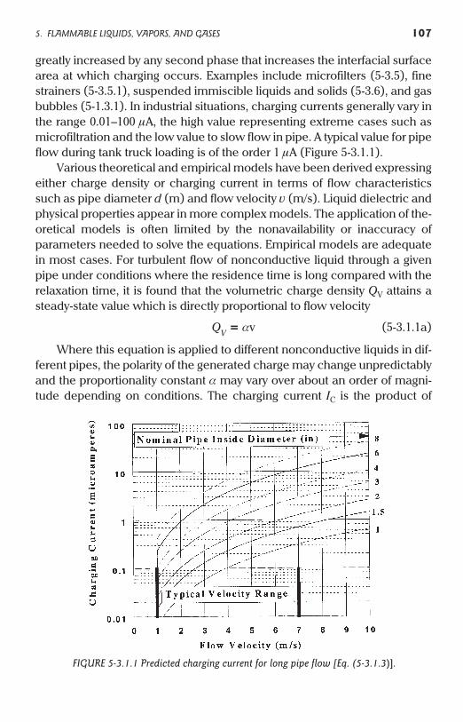
greatly increased by any second phase that increases the interfacial surfacearea at which charging occurs. Examples include microfilters (5-3.5), finestrainers (5-3.5.1), suspended immiscible liquids and solids (5-3.6), and gasbubbles (5-1.3.1). In industrial situations, charging currents generally vary inthe range 0.01–100 mA, the high value representing extreme cases such asmicrofiltration and the low value to slow flow in pipe. A typical value for pipeflow during tank truck loading is of the order 1 mA (Figure 5-3.1.1).
Various theoretical and empirical models have been derived expressingeither charge density or charging current in terms of flow characteristicssuch as pipe diameter d (m) and flow velocity v (m/s). Liquid dielectric andphysical properties appear in more complex models. The application of the-oretical models is often limited by the nonavailability or inaccuracy ofparameters needed to solve the equations. Empirical models are adequatein most cases. For turbulent flow of nonconductive liquid through a givenpipe under conditions where the residence time is long compared with therelaxation time, it is found that the volumetric charge density QV attains asteady-state value which is directly proportional to flow velocity
QV = av (5-3.1.1a)
Where this equation is applied to different nonconductive liquids in dif-ferent pipes, the polarity of the generated charge may change unpredictablyand the proportionality constant a may vary over about an order of magni-tude depending on conditions. The charging current IC is the product of
5. FLAMMABLE LIQUIDS, VAPORS, AND GASES 107
FIGURE 5-3.1.1 Predicted charging current for long pipe flow [Eq. (5-3.1.3)].
charge density (QV) and volume flow rate (vpd2/4). If we assume that a
might be a function of pipe diameter
IC = bvxdy (5-3.1.1b)
where b, x, and y are constants.Various proposed values for the constants can be found in the literature
[8]. Despite double-layer model predictions [148,149] that exponents x and yare both unity, and a dimensional analysis model [204] giving x as 1.88 and yas 0.88, test work on a practical scale [202,203] has indicated that both expo-nents are approximately equal to 2. This implies that a is roughly independ-ent of pipe diameter and that the ratio a/b @ 4/p @ 1.
The charging current IC is therefore roughly proportional to the square of(vd), the velocity–diameter product. An important outcome is that the veloc-ity–diameter product can be used to characterize charging current in pipeflow and as a basis for setting flow limits when filling tanks (5-4).
For QV in C/m3, constant a has been reported in the range (4.77 – 31.8) ´
10–6 Csm–4. For IC in Amperes, constant b has been reported in the range(3.75 – 25) ´ 10–6 Csm–4; this follows directly from the relation a/b = 4/p.The low values corresponded to turbulent flow through long, smooth pipewhile the high values corresponded to turbulent flow through spiral-woundcomposite hose [8]. An order of magnitude value for both a and b is there-fore 1 ´ 10–5 Csm–4. As shown in [55], whatever assumptions are madeconcerning the charging current at the pipe wall, steady-state in turbulentflow is exponentially approached according to the modifying term1 – exp[–t/t], where the residence time t can be written as the length-to-velocity ratio L/v. This is reflected in Eqs. (5-3.1.2) and (5-3.1.3).
Assuming that the x and y exponents in Eq. (5-3.1.1.b) are indeed 2, it fol-lows that to within a factor of about ±3 the charge density and charging cur-rent in pipe exponentially approach their long pipe values according to
QV (mC/m3) @ 10v1 – exp[–L/(vt)] (5-3.1.2)
IC (mA) @ 10 (vd)2 1– exp[–L/(vt)] (5-3.1.3)
where velocity v is given in m/s and the pipe inside diameter d and length Lare given in meters. “Long” pipe has a liquid residence time (L/v) that is largecompared with liquid relaxation time (t), so that the exponential correctionterm is small compared with other errors and can be neglected. Figure5-3.1.1 shows predicted “long” pipe charging currents for a series of pipediameters, conveniently expressed in inches.
As discussed in 5-4.2 and 5-4.3, three different maximum velocity–diam-eter (vd) products can be found in current recommended practices. Values
108 5. FLAMMABLE LIQUIDS, VAPORS, AND GASES
of 0.38 (this book) and 0.50 m2/s (API 2003) have been recommended forroad tanker filling. Values of 0.50 (this book) and 0.80 m2/s (API 2003) havebeen recommended for rail car filling. From Eq. (5-3.1.3) these vd products(0.38, 0.50, and 0.80 m2/s) yield predicted “long” pipe charging currents of1.4, 2.5, and 6.4 mA, respectively. The charging current approximately dou-bles between these pairs of vd products. The significance of this with respectto faster loading times versus risk tolerance is discussed in 5-4.
An important practical question is, “what is the representative pipediameter in loading circuits comprising different sizes of pipe?” This has alarge effect on the values calculated for velocity and velocity-diameter prod-uct. As an example, static ignition of ester mist in a rail car (5-1.3.1) involved1450 gpm through a 6-in. pipe (v = 5 m/s and vd = 0.76 m2/s) followed by ashort 4-in. dip pipe assembly (v = 11 m/s and vd = 1.15 m2/s). Werenonconductive liquid flow rate restrictions applied to the semiconductiveester (time constant ~0.01 s) involved in this fire, the flow rate based on the4-in. pipe would be unacceptably large based either on a 7 m/s maximumvelocity or a 0.80 m2/s maximum vd product. However, based on the 6-in.pipe upstream the flow velocity is less than 7 m/s and also meets API’svd £ 0.80 m2/s criterion.
The velocity–diameter product should usually be assessed for the pipeentering or terminating at the tank, neglecting restrictions such as tees orcruciform outlets on dip pipes. However, in top loading the pipe is oftennecked down at the rack to accept a smaller diameter hose followed by thedip pipe. The total length of smaller diameter hose plus pipe is only a fewmeters, which for liquids having time constants of several seconds does notconstitute “long” pipe using Eq. (5-3.1.3). BS 5958 [2] assumes that onlynonconductive liquids having time constants of about 1 s or more can accu-mulate hazardous charge densities in road and rail tankers. It thereforeallows vd to be assessed on the basis of larger diameter upstream pipe incases where the pipe entering the tank is relatively short and presumablyunable to generate its correspondingly greater “long” pipe charging current.BS 5958 allows credit to be taken provided the smaller pipe is less than 10 mlong and only one pipe size smaller than the larger pipe upstream (diameternot less than 67% that of the larger pipe).
In reality the charging current increases in the smaller diameter dip pipe.Also, small diameter spiral-wound hose can in some cases greatly increasecharging current. This effect is presumed due to increased turbulence at theinner wall [8]. For overhead filling of road and rail tankers the maximum vdproducts recommended in this book are respectively 0.38 m2/s and 0.50m2/s, which are smaller than the maximum recommended values given in
5. FLAMMABLE LIQUIDS, VAPORS, AND GASES 109
API 2003 and BS 5958. This took into account the possibility that credit mightbe taken for larger upstream pipe as described in BS 5958 and that opera-tional errors such as partial dip pipe insertion might occur.
5-3.1.2. Pro-Static AgentsThis concept was introduced to help explain the unexpected occurrence of“static” fires and explosions during fuel loading operations where there hadbeen no apparent change in procedure. Should pro-static agents exist, theirprincipal characteristic would be to increase the charging tendency withoutsignificantly increasing the conductivity. The charging current as governed,for example, by constant b in Eq. (5-3.1.1b), would be significantly increasedwhile the rate of charge dissipation in a downstream tank, governed by con-ductivity, would remain unaffected. Hence, the rate of charge accumulationand magnitude of surface potential in the tank would increase. An unrecog-nized and equally important effect of a pro-static agent is to promote nega-tive as opposed to positive charging. Brush discharges are only likely tocause ignition if they originate from negatively charged liquid surfaces(2-6.2).
The charge transfer mechanism in hydrocarbon fuels may be affectedby a wide variety of additives and contaminants (2-3.1). An investigation con-cluded that certain fuel additives (corrosion inhibitors, thermal stability andantioxidant additives) can exert a pro-static charging effect [151]. The fuelcomponents most electrostatically active were sodium sulfonates, particu-larly those derived from petroleum. The activity was highly dependent onchemical structure although there was a trend for the highest activity tooccur at the lowest molecular weight in a given homologous series. Withrespect to the sulfonate observations, low-sulfur fuels are usually electro-statically active; it appears that the removal of electrostatically active speciesis more than compensated for by the accompanying conductivity reduction.
Suspended water is known to greatly increase charging as discussed in5-3.6 and 5-3.7. However, it has been shown that dissolved water can be ahighly effective pro-static agent [151]. Under some test conditions, involvingfiltration charging, the charging tendency due to dissolved water increasedby about one order of magnitude while the fuel conductivity actuallydecreased. In general, dissolved water had a variable effect on conductivityof different hydrocarbons; the conductivity could increase, decrease orremain about the same. Since water did not increase the charging tendencyof silica-gel treated n-heptane it was concluded that water is not a pro-staticagent per se but instead interacts with some minor constituent in the fuelthat is removable by silica gel. The effect of additives on conductivity may be
110 5. FLAMMABLE LIQUIDS, VAPORS, AND GASES
synergistic (5-2.6) and it appears that synergy might also exist betweenpro-static agents, for example between a minor constituent and water. Thepossible effects of pro-static agents should be considered if velocity–diameter products greater than the recommended values (5-4) are used.
5-3.2. Nonconductive Pipe and Linings
Nonconductive plastic surfaces affect the rates of both generation and lossof charge during flow through pipe. Although the charging current in plasticpipe has been found to decrease with increased flow time it should beassumed that the charging rate is similar to that in metal pipe. Also, if theliquid is not conductive the pipe walls may become strongly charged. Fornonconductive and some semiconductive liquids, insulation by the pipewall can result in charge accumulation which may eventually lead to electri-cal breakdown and “pinhole” punctures either of the plastic lining or (forall-plastic pipe) the entire wall thickness. This has created problems in flam-mable liquid (such as xylene) and nonflammable liquid (such as silicontetrachloride) service. For all-plastic above-ground pipe, external electricfields created by the accumulated charge may also cause static dischargesfrom the external wall to neighboring conductive objects. These effects aregenerally not observed for conductive liquids (k > 104 pS/m). During drain-ing of lined pipe, nonconductive liquids might give rise to internal dis-charges, for example at metal connections, if the lining has accumulated alarge surface charge density. Such discharges might ignite flammable mix-tures inside the pipe. The hazard may be mitigated by using asemiconductive lining, blowing down the line with nitrogen, or providing await time for excessive charge to relax from the lining. The wait time recom-mended in section 19.8.3 of Part 2 of BS 5958 [2] is the shorter of the twotimes
a. t1 = 3 relaxation times of the pipe lining material = (3rer e0) where r
= volume resistivity of lining material in W-m and er = dielectric con-stant of lining material. Note that dielectric constant is dimensionlessand does not have units of W-m as given in the 1991 edition of BS 5958.
b. t2 = [L2er e0 / (drk)] where L = distance between grounded pointsin contact with the liquid at ends of lined pipe section (m), d = liningthickness (m), r = pipe radius (m) and k = liquid conductivity (S/m).Note that the 1991 edition of BS 5958 incorrectly expresses the units ofliquid conductivity in pS/m. The equation as given in BS 5958 there-fore yields results that are one trillion (1012) times too small.
5. FLAMMABLE LIQUIDS, VAPORS, AND GASES 111
Both of these wait times can be impractically long. Using (a) the waittime is 2.2 hrs for a lining having a resistivity of 1014 W-m and dielectric con-stant of 3. Using the corrected equation (b), a 2-mm-thick lining of the samematerial in a 10-cm-radius pipe, 10 m between grounded points, beingdrained of toluene having a conductivity of 1 pS/m, has an impractical waittime of 154 days. The wait time given by (b) only achieves reasonable valuesfor conductive liquids, in which case there should be no static accumulationproblem in the first place. BS 5958 provides no rationale or literature refer-ence for equation (b), which is evidently useless with or without correction.
Pipe with high resistivity lining that contains semiconductive ornonconductive flammable liquids should be blown down with nitrogenrather than air. To avoid pinhole damage, the flow rate during blow-downshould be no higher than normal liquid flow rate. Also, the possible hazardscreated in downstream tanks by charged, two-phase flow should be consid-ered (5-2.5.4).
5-3.2.1. All-Plastic PipeOwing to symmetry about the axis, a long plastic pipe whose walls are uni-formly charged contains zero internal field, because the field contributionsfrom diametrically opposite charges exactly cancel one another. Internalfields only exist where the field symmetry is perturbed near the pipe ends, orby conductive or charged objects external to the pipe. When a plastic pipecontains charged liquids or powders an internal field will be created, but inmost cases the internal field is small owing to the small pipe diameter. Plas-tic pipes may create large external fields due to either internal or externalcharges. Because the internal field is small, very large internal charge densi-ties can be accumulated without breakdown taking place; because the fieldis exerted radially through the pipe wall, electrical breakdown can onlyoccur through the pipe wall itself. Since breakdown voltages can exceed100 kV for a few millimeters of plastic, very large energies can be stored inplastic pipe walls before a breakdown occurs (2-6.5.3). PBDs may be pro-duced from plastic pipe following internal charging either via flow of powderor charged liquid (2-6.5.2). Owing to end effects, a certain minimumlength-to-diameter ratio may be required for PBDs to occur and puncturing isleast likely to occur close to the pipe ends (5-3.2.3).
All-plastic nonconductive pipe such as polyolefin is not recommendedfor handling nonconductive or semiconductive liquids except where it canbe shown that the advantages outweigh any risks associated with externalstatic ignition or leakage via pinholes, or where tests have demonstrated thatthe phenomena will not occur. Burying an all-plastic pipe prevents external
112 5. FLAMMABLE LIQUIDS, VAPORS, AND GASES
ignition risk in the buried section but will not necessarily rule out leakagedue to pinholes should large charge densities accumulate. PVC and espe-cially fiber-reinforced polyester (FRP) pipe should be considered separatelyfrom polyolefin pipe owing to the considerably smaller resistivities typical ofthese materials. The characteristics of FRP are highly variable and over timeboth the resistivity and breakdown voltage typically decline due to the devel-opment of minute cracks; this behavior is pronounced when FRP is usedoutside and subjected to freezing weather.
Plastic-lined metal pipe poses no external ignition hazard and will nor-mally provide containment in the event of pinhole puncturing of the lining.However, the tolerability of pinholes in the lining should be considered. Forexample, if the liquid is corrosive to the metal pipe, gradual loss of metal viathe pinholes might lead to unacceptable product contamination and eventual loss of containment. Conversely, minor pinhole damage may be acceptable if the lining is intended only to minimize product discoloration caused by rust and scale.
5-3.2.2. Mitigation for Plastic Pipe HazardsWhere nonconductive and semiconductive liquids must be transferredthrough plastic piping systems, mitigating strategies include
• Reduce rate of charging such as by decreasing flow velocity.• Eliminate or relocate microfilters farther upstream.• Reduce wall resistivity, possibly to less than 108 W-m.• Increase breakdown voltage of wall by increasing thickness and/or
changing material of construction.• Incorporate external grounded conductive layer on pipe.
Combinations of these strategies might be considered. For example, inmany cases the presence of an external conductive layer on a plastic pipewill not by itself eliminate puncturing of the internal plastic wall, and if thelayer does not provide containment it will not prevent external leakage.
5-3.2.3. Plastic Tubing and Small Bore HoseIn 1959 a number of failures occurred in small bore hose used for aircraftfueling, which developed pinhole leaks caused by electrostatic puncturing.All of the hose was extruded Teflon tubing with braided stainless steel rein-forcing wire [164]. Failures were found on operating aircraft and it wasnoted that the condition might go unnoticed for extended periods and thenbe misdiagnosed. All of the failures occurred in hose more than 18 in. long,no punctures occurred within 2 in. of the end fittings, times-to-failure variedfrom a few minutes to 2000 hours, multiple punctures could occur, and the
5. FLAMMABLE LIQUIDS, VAPORS, AND GASES 113
punctures appeared like fractures when viewed under the microscope. Itwas estimated that voltages of about 50 kV were responsible for the electri-cal breakdowns. Following an extensive investigation, conductive Teflonwas developed having the proper quantity and distribution of carbon blackto dissipate the static while not adversely affecting other material properties.Later work [205] concluded “considering pipes or hoses through which ahighly charged petroleum liquid may flow, an electrical resistance fromeach and any portion of the interior surface of the pipe to ground not exceed-ing about 107 W is adequate to limit pipe potentials resulting from static elec-tricity to less than 1000 V.”
Flexible tubing for high pressure service, equipped with stainless steeloverbraid plus tube adapter end connections, is commonly available with acarbon black-loaded PTFE core tube to dissipate static. Numerous otherdesigns of conductive and antistatic tubing are available for low pressureapplications. The utility of conductive tubing in preventing fires during trans-fer of aromatic hydrocarbon liquids is described in [165].
5-3.3. Flexible Hoses
These are available in all-metal, lined metal, reinforced rubber/plastic, orcomposite ply types. Nonconductive hoses should not be used in flammableliquid service or in flammable vapor atmospheres. Also, if used immediatelydownstream of filters in nonconductive or semiconductive liquid service,hoses should be flexible metal, semiconductive or thick-walled conductivetypes. In some cases semiconductive linings might be necessary to preventcharge accumulation and pinhole puncture damage to conductive hoses.Conductive hoses should be electrically continuous via the embedded metalbonding element; the latter should be properly bonded to the end connec-tors and the continuity should be periodically checked. As shown schemati-cally in Figure 5-3.5, the type of hose can affect static generation and there isevidence [8] that internal spiral-wound hoses of small diameter (1.5–2.0 in.)generate more static than smooth bore hoses, presumably due to greaterturbulence at the wall. For vacuum truck operations, see 5-4.6.
5-3.3.1. Bonding and Grounding of HosesThe resistance to ground from any point along a flexible metal conductivehose should be 10 W or less except where insulating flanges are employed toavoid stray current arcs.
Conductive hoses containing a continuous wire or braid bonding ele-ment should have a resistance £1 kW per meter of hose length and the resis-tance to ground from any metal connector should be less than 1 MW.
114 5. FLAMMABLE LIQUIDS, VAPORS, AND GASES
The resistance to ground through semiconductive hoses, whose cur-rent-limiting design eliminates a low resistance bonding element, andthrough insulating flanges, should be between 103 and 105 W per meter ofhose length (or intermediate range as specified by a manufacturer) basedon measurement between the end connectors; the total resistance toground from a metallic hose connector should not exceed 1 MW.
A resistance to ground less than 1 MW will prevent static accumulation inpractical cases. However, if periodic testing reveals a significant increase inthe “as installed” value the hose and/or insulating flange should be evalu-ated for replacement. This is because the increased resistance could indi-cate corrosion or other damage that could lead to sudden loss of continuity.Where conductive hoses have double spirals (one for bonding and the otherfor mechanical strength) continuity between the end connectors need onlyimply continuity of one spiral. A fire was reported during draining of toluenefrom a road tanker through such a hose and after the event it was found thatthe inner spiral was not only broken but was not designed to be bonded tothe end connectors. Two post-loading toluene fires occurred with a similarhose as the disconnected hoses were being handled by operators [166]. Fornonconductive liquid handling especially, hoses should be selected withcare. An option is to use a hose with a semiconductive or conductive liningso that a broken inner spiral cannot become isolated from ground and forma spark gap, and static rapidly drains from the hose after use. In any case theinner spiral should be designed so that it is firmly bonded to both end con-nectors. It is especially important to ensure continuity with end connectors(or nozzles) where a hose is used in a flammable atmosphere. In general it issafer to use a properly designed fixed filling system such as a dip pipearrangement than to use a hose in tank filling operations.
5-3.3.2. Utility HosesThese do not normally create a static hazard. However, where used in flam-mable vapor atmospheres such as inside tanks, these should be conductiveor semiconductive and in particular it should be ensured that metal connec-tors and nozzles are grounded. See 5-3.3.1 for grounding requirements.Ungrounded hose connectors on nonconductive hose may becomecharged by a variety of mechanisms, such as by inserting a nitrogen hoseinto a tank containing charged liquid or mist. Although clean, dry gases donot generate charge, a nonconductive hose may become highly charged bythe flow of steam. Typically, special conductive hoses are reserved for steamservice.
5. FLAMMABLE LIQUIDS, VAPORS, AND GASES 115
5-3.4. Dip Pipes
See “Splash Filling” in 5-2.3.1. Dip pipes should be metallic, grounded, andpermanently fixed where possible. Explosions have occurred where plasticdip pipes were used, both during filling and emptying operations. The ves-sels involved ranged in size from drums [8] to barge tanks [172]. The pur-pose of the dip pipe is either to load a vessel with minimal disruption ofbottom sediment and mist production associated with splashing, or toempty a vessel. The dip pipe should extend close to the bottom of the vesselwithout touching it, and might be equipped with either a 45 degree cut or atee to divert flow horizontally near the base of the vessel being filled. Thedesign should prevent upward spraying during the initial stages of filling andthis is typically achieved by using a “slow start” such that inlet velocity is heldat less than 1 m/s until the dip pipe outlet is covered by at least 6 in. or twopipe diameters of liquid, whichever is greater. To prevent siphoning, a dippipe may in some cases need to be equipped with an appropriate vacuumbreaker such as breather holes.
5-3.4.1. Thrust NeutralizersSideways ejection of liquid at the foot of a dip pipe, via tees or cruciform out-lets, can be used to reduce upward thrust forces in addition to the benefitsnoted in 5-3.4. However, it is important that the dip pipe not be partly insertedin a tank since this can exacerbate the static hazards. Sideways ejection ofliquid via a right angle turn increases shear forces and static generation rate(5-1.3.1). If the pipe outlet is not fully submerged this will be accompanied bysplashing and the production of mist or foam, which may result in a flamma-ble atmosphere even below the flash point of the liquid being loaded. Also,the blunt end of a partly inserted dip pipe suspended above a charged liquidsurface can be most effective in generating brush discharges.
5-3.5. Filters and Relaxation Tanks
Microfilters have a nominal pore size ranging from less than 1 mm up to150 mm. Owing to the high solid–liquid contact area, large charging currentsare generated in nonconductive and many semiconductive liquids. Thecharging current increases as pore size decreases and is frequently about 2orders of magnitude greater than the charging current developed in the pipeupstream of the microfilter (Figure 5-3.5). Charge densities in nonviscousoils such as kerosene can attain 2000–3000 mC/m3 with little dependence onflow rate [8], although charging current is at least proportional to flow rate
116 5. FLAMMABLE LIQUIDS, VAPORS, AND GASES
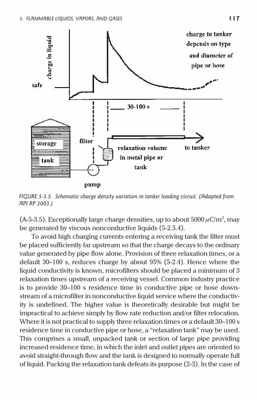
(A-5-3.5). Exceptionally large charge densities, up to about 5000 mC/m3, maybe generated by viscous nonconductive liquids (5-2.5.4).
To avoid high charging currents entering a receiving tank the filter mustbe placed sufficiently far upstream so that the charge decays to the ordinaryvalue generated by pipe flow alone. Provision of three relaxation times, or adefault 30–100 s, reduces charge by about 95% (5-2.4). Hence where theliquid conductivity is known, microfilters should be placed a minimum of 3relaxation times upstream of a receiving vessel. Common industry practiceis to provide 30–100 s residence time in conductive pipe or hose down-stream of a microfilter in nonconductive liquid service where the conductiv-ity is undefined. The higher value is theoretically desirable but might beimpractical to achieve simply by flow rate reduction and/or filter relocation.Where it is not practical to supply three relaxation times or a default 30–100 sresidence time in conductive pipe or hose, a “relaxation tank” may be used.This comprises a small, unpacked tank or section of large pipe providingincreased residence time, in which the inlet and outlet pipes are oriented toavoid straight-through flow and the tank is designed to normally operate fullof liquid. Packing the relaxation tank defeats its purpose (2-3). In the case of
5. FLAMMABLE LIQUIDS, VAPORS, AND GASES 117
FIGURE 5-3.5. Schematic charge density variation in tanker loading circuit. (Adapted fromAPI RP 2003.)
viscous nonconductive liquids, charge relaxation is too slow for these mea-sures to be effective. Other mitigation such as inerting should be consideredwhere a flammable atmosphere is present in the receiving tank (5-2.5.4).
Care should be taken when performing maintenance on microfilter ele-ments wet with flammable liquid since sparks from ungrounded people orelement parts during disassembly or element disposal have led to numerousfires. Where plastic bags are used for disposal they should be conductive orantistatic. In cases where spontaneous combustion might occur, for exam-ple where numerous filter elements containing combustible liquids are col-lected together, bags should be sealed after first (if compatible) wetting thecontents with water.
5-3.5.1. StrainersMesh strainers finer than 100 mesh/inch (<150 mm) should be treated asmicrofilters. Coarser strainers up to 50 mesh/inch (300 mm) may generatesignificant static when fouled with accumulated debris, so should be treatedas microfilters except in cases where fouling is not expected or may be rap-idly identified by either periodic inspection or monitored pressure drop.“Clean” strainers should nevertheless be placed as far upstream as practicalfor nonconductive liquid service. A theoretical model for the charging pro-cess in strainers (screens) is given in [119–120]. Viscous nonconductive liq-uids (5-2.5.4) may produce unusually high charging currents in strainers.
5-3.5.2. End-of-Line “Polishing” FiltersThese filters are sometimes used in cases where an upstream filter fails toprovide adequate quality control, typically because of scale in the linebetween the filter location and the tank. Often such a filter is installed on theend of a hose and the filter element might be directly exposed to vapor in thetank. During cold weather, static discharges were observed on such a filterduring transfer of semiconductive n-butyl acetate having a conductivity ofabout 2000 pS/m. Fortunately the liquid was well below its flash point.Unhoused polishing filters should not be used in flammable liquid service.For conductive and semiconductive liquids, the provision for three relax-ation times (5-3.5) is simple to achieve with a grounded metal lance down-stream of the filter. However, for nonconductive flammable liquid service apolishing filter should be used only in inerted atmospheres.
5-3.6. Suspended Material
Aeration of liquids not only increases charging due to the large liquid–bubbleinterfacial area but can also produce hazardous conditions in downstream
118 5. FLAMMABLE LIQUIDS, VAPORS, AND GASES
equipment. Even if a downstream tank is inerted, the incoming aeratedliquid may produce an ignitable froth (5-1.3.1). Immiscible or poorly solubleliquids may disperse as droplets or as an emulsion. Where a nonconductiveliquid contains a dispersed phase such as water in oil, the continuous phasedetermines the charge relaxation behavior while the charging behavior isrelated to the electrical double layer formed at the interface between thetwo phases. The total interfacial area of the dispersed material can be veryhigh compared with the boundary contact area where charging would oth-erwise occur. Hence, charge generation is generally greater for such suspen-sions than for a single phase liquid. Double layer shear can occur duringflow, pumping, filtration or settling of suspended liquids or solids to the baseof a tank. For water in oil, the effect of the second phase is appreciableabove about 0.5 wt%. Where a dispersed phase is expected, additional pre-cautions such as the reduction of flow velocity to about 1 m/s, or inerting,should be considered. Where lines contain low points that might collectwater, the flow velocity should not be maintained at less than 1 m/s forextended periods. This is because a large concentration of water previouslycollected in the low points could be flushed out when the flow rate isincreased. For mixing operations see 5-4.4.
5-3.7. Valves and Other Line Restrictions
Items such as orifice plates, valves, elbows and tees increase turbulence andmay result in increased charge density downstream. Suspended materialsuch as water (5-3.6) has been found to greatly increase this effect; for exam-ple 1–5 wt% water in toluene produced 580–620 mC/m downstream of apartly open 4-in. ball valve [20], which was about 20 times the charge densityobserved for pure toluene flow under the same conditions. Where anonconductive liquid contains upward of 0.1% by volume of free water andthis type of flow restriction exists immediately upstream of a receiving tank,flow velocity should be restricted to about 1 m/s or less [20]. This compareswith the more general recommendation (5-3.6) to apply this restrictionabove 0.5 wt% free water in unrestricted pipe flow. Smaller charge densitiesare generally produced during unrestricted, straight pipe flow. Anotherreported effect of ball valve electrification is sparking from valve handlesinsulated by the packing; special ball valves have been designed which pro-vide a resistance less than 10 W between ball, spindle and outer casing [19].If electrical continuity with the valve body is not found with the handle in allpossible positions, the handle should be separately bonded.
5. FLAMMABLE LIQUIDS, VAPORS, AND GASES 119
5-4. Filling Criteria for Tank Operations
Filling criteria for grounded metal tanks are intended to restrict the maxi-mum liquid surface potential to less than the threshold value at whichincendive brush discharges can occur to a grounded electrode above theliquid (A-5-4). As a tank is filled with charged liquid the surface potentialincreases and usually passes through a maximum value at the center of thefree liquid surface when the tank is 30–50% filled. It is assumed that thecharged liquid in the tank has a small conductivity and is well mixed so thatthe charge density is approximately uniform (5-2.4).
The relationship for liquid surface potential F during tank filling is of theform [22]
F = kQV f (tank dimensions and liquid depth) (5-4.1)
where k is a constant and QV is the charge density in the tank, given as atime-dependent variable by
QV (t) = (ICt / Vt)1 – exp(–t/t) (5-2.4.4)
The liquid surface potential is proportional to the charge density in thetank (QV), which in turn is roughly proportional to the charging current (IC).The charging current is roughly proportional to the square of vd , the veloc-ity–diameter product (5-3.1.1). The maximum liquid surface potential there-fore varies approximately with the square of the velocity–diameter productof the liquid in the filling pipe. A relatively small increase in velocity cantherefore result in a magnified increase in ignition probability as reflected byan increased surface potential. Neglecting any slow start, if a 7000-gallonroad tanker is filled through 4-in. pipe, a vd of 0.38 m2/s corresponds to a fill-ing time of about 14.6 min and a vd of 0.50 m2/s corresponds to a filling timeof 11.1 min. In order to save this 3.5 min of filling time, the vd product hasbeen increased by a factor of 1.32 and the surface potential in the tank hasbeen increased approximately by the square of this number, or 1.73. Thissimplified analysis shows that there can be a large assumption of risk foronly small benefit in reduced filling time.
Since velocity varies with the inverse square of pipe diameter d, animportant consideration is the selection of pipe diameter. For any givenvelocity-diameter product, larger pipe diameters allow larger flow rates.Since occasional static ignitions in road tankers may occur at vd = 0.38 m2/s,smaller values might be considered for nonconductive liquid transferdepending on risk tolerance.
Table 5-4 gives solutions for various tank filling criteria discussed in thischapter in which either a maximum velocity or a maximum velocity–diame-
120 5. FLAMMABLE LIQUIDS, VAPORS, AND GASES
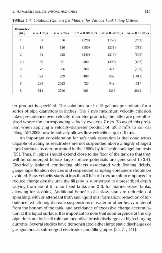
ter product is specified. The solutions are in US gallons per minute for aseries of pipe diameters in inches. The 7 m/s maximum velocity criteriontakes precedence over velocity–diameter products; the latter are parenthe-sized where the corresponding velocity exceeds 7 m/s. To avoid this prob-lem when applying a velocity–diameter product of £0.8 m2/s to rail carfilling, API 2003 now tentatively allows flow velocities up to 10 m/s.
An important consideration for safe tank operation is that conductorscapable of acting as electrodes are not suspended above a highly chargedliquid surface, as demonstrated in the 1950s by full-scale tank ignition tests[55]. Thus, fill pipes should extend close to the floor of the tank so that theywill be submerged before large surface potentials are generated (5-3.4).Electrically isolated conducting objects associated with floating debris,gauge tape flotation devices and suspended sampling containers should beavoided. Slow velocity starts at less than 3 ft/s or 1 m/s are often employed toreduce charge density until the fill pipe is submerged to a prescribed depthvarying from about 6 in. for fixed tanks and 2 ft. for marine vessel tanks,allowing for sloshing. Additional benefits of a slow start are reduction ofsplashing, with its attendant froth and liquid mist formation, reduction of tur-bulence, which might create suspensions of water or other heavy materialfrom the bottom of the tank, and avoidance of excessive charge accumula-tion at the liquid surface. It is important to note that submergence of the dippipe does not by itself rule out incendive brush discharges at high chargingcurrents. Several studies have demonstrated either large static discharges orgas ignitions at submerged electrodes and filling pipes [35, 71, 141].
5. FLAMMABLE LIQUIDS, VAPORS, AND GASES 121
TABLE 5-4. Solutions (Gallons per Minute) for Various Tank Filling Criteria
Diameter(in.) v = 1 m/s v = 7 m/s vd = 0.38 m2/s vd = 0.50 m2/s vd = 0.80 m2/s
1 8 56 (120) (158) (253)
1.5 18 126 (180) (237) (379)
2 32 225 (240) (316) (506)
2.5 50 351 300 (395) (632)
3 72 506 360 474 (758)
4 128 899 480 632 (1011)
6 289 2023 720 948 1517
8 514 3596 961 1264 2022
Another important consideration is the allowance of a “wait time”before introducing objects that could act as electrodes, such as sample con-tainers and gauge rods. The maximum liquid surface potential typicallyoccurs when the tank is 30–50% filled and is proportional to the charge den-sity in the tank. As flow to the tank is started or stopped the charge densityrapidly rises to a geometry-dependent maximum value or falls to zero, asgoverned by the dimensionless group t/t in Eqs. (5-2.4.4) and (2-3.7). As dis-cussed in [195] the surface potential on a liquid with a conductivity of 15pS/m rises to its maximum value or falls close to zero in only a few seconds.An important consequence is that discharged liquid already in the tank does
being stopped, the surface potential quickly regains or exceeds the value
5-4.1. Storage Tanks
The maximum liquid surface potential attained in tanks depends not onlyon the liquid charge density, tank volume and filling rate, but also on thetank dimensions [69,191]. For commercial tanks of equal volume, themaximum potential is greater in tanks having smaller cross-sectional areassince liquid depth is built up faster relative to the rate of charge relaxation.Smaller potentials are therefore generated in a barge tank than in a verticalcylindrical tank of equal volume. The competitive rates of charge input anddecay vary with tank dimensions and liquid properties while the loadingrates and pipe diameters used in practice also vary with tank volume.Hence, no single set of filling recommendations, such as a maximum flowrate for a specified inlet pipe diameter, can efficiently address all sizes andshapes of tank. The liquid surface potential is proportional to the chargedensity in the tank, which under well-stirred conditions varies with timeaccording to
QV(t) = (ICt/Vt )1 – exp(–t/t) (5-2.4.4)
122 5. FLAMMABLE LIQUIDS, VAPORS, AND GASES
not safely “dilute” charged liquid flowing to the tank. If flow is restarted after
that previously existed. Owing to charge stratification, multistage loading ofroad tankers can result in transient surface potentials that are greater thanthose produced by continuous filling; a number of loading fires have
in the range 30-100 s (5-2.4.1), so wait times of 5–10 min. are adequate forrelatively small tanks such as road and rail tankers. In the case of large
for complicating effects such s settling potential (5-4.1.2).storage tanks and ships' tanks a 30-min wait time is recommended to allow
occurred under such conditions[195]. The worst case relaxation time is
Liquid relaxation times are normally less than 30–100 s while tank fillingtimes generally exceed 1000 s. The exponential term in Eq. (5-2.4.4) is there-fore negligible by the time most tanks are 30–50% filled. Hence
QV (t) @ ICt/Vt (5-4.1.1)
or
QV (t) @ ICt/(Ft) (5-4.1.2)
where F is the volume flow rate and t the time to accumulate volume Vt.From Eq. (5-2.2) the charging current IC can be replaced by FQV(0) whereQV(0) is the charge density entering the tank. Hence
QV (t)/QV(0) @ t/t (5-4.1.3)
Equation (5-4.1.3) shows that the fraction of the incoming charge densityremaining in the liquid decreases during filling and achieves very smallvalues where t >> t, such as in large tanks that are 30–50% filled. Thisdecreasing charge density offsets the larger potentials attained in largertanks due strictly to their greater cross-sectional areas. Another mitigatingfactor in large tanks is that the incoming charge density is proportional toflow velocity [Eq. (5-3.1.2)] and therefore cannot be indefinitely increased;apart from practical limitations, it has for many years been common practiceto limit flow velocity to less than 7 m/s. Worst case conditions in terms oftank size and charge density should develop at some intermediate tankvolume; depending on tank shape and other factors this might be in therange 103–104 gallons.
Large storage tanks usually present less hazard than those of intermedi-ate size such as road tankers, since it becomes impractical to fill themsufficiently fast to offset charge relaxation as liquid level builds. Use oflarge-diameter pipe tends to offset charging caused by high flow rates (Table5-4). It is sufficient to limit flow velocity to less than 7 m/s for tanks exceedingabout 100 m3 or 26,000 gallons; a typical volume for a rail car is 23,000gallons. For large-diameter lines supplying large tanks this velocity is oftenlimited by the pump capacity. Because pumping rates can be difficult to con-trol procedurally, avoidance of excessive flow rates might need to be engi-neered into the system design.
5-4.1.1. Floating Roof TanksThese tanks are designed to reduce evaporation and vapor emission. Twodistinct designs are those with and those without an additional fixed roof. Ofthe former types, known as internal floating roof tanks, various provisions
5. FLAMMABLE LIQUIDS, VAPORS, AND GASES 123
may be made for ventilating the space between the floating roof and thefixed roof. Fires may occur around the rim of a floating roof, and if adequateventilation is not provided flammable vapor may accumulate between thefloating roof and a fixed roof. Apart from lightning, static electricity is an issueonly when a grounded, conductive floating roof is not afloat (that is, whenlow liquid level results in the roof settling on its supports) or personnel needto be on the upper side of the roof. When the roof is not afloat, liquids shouldbe loaded at 1 m/s or less, after which the velocity can be increased to thenormal design rate. Excessive flow rates and conditions such as aerationmay cause a floating roof to tilt or even sink. In such an event, it may be nec-essary to apply foam to the liquid surface to suppress evaporation andreduce fire risk. If this is done, the foam should be applied at, and tangentialto, the wall so that it spreads from the grounded wall toward the tank centerwithout creating isolated patches. Fires have been sparked by isolatedpatches of conductive foam due to residual charge in the underlying liquid.The floating roof engages the tank wall via special “shoes” which in practicemay fail to provide proper grounding. A separate grounding cable is some-times used to bond the roof internally to its internal supports. When receiv-ing flammable liquid such as gasoline into an empty internal floating rooftank it should be assumed that a flammable vapor space may persist belowthe fixed roof for 12–18 h after the floating roof has begun to float [156]. Thearea on top of the floating roof is considered a confined space and the atmo-sphere must be tested for flammable vapor prior to and often during anyactivity involving personnel on the roof.
5-4.1.2. Settling PotentialGravitational separation of nonmiscible phases such as oil–water, solid–liquid or liquid–air mixtures results in charge separation. In the case of solidparticles in liquids the phenomenon is sometimes known as the “Dorneffect.” The mechanism involves formation of an electrical double layeraround the dispersed particles comprising an inner layer of charge which ismore tightly bound than an outer “diffuse” layer. Movement of the particlesrelative to the continuous phase shears the inner from the outer chargelayer, causing a net charge to be carried by the dispersed phase [55,148].The best known example is transfer of water-oil mixtures into large tanks,causing the generation of a “settling potential” as the water droplets settleout. This is an unlikely ignition mechanism for most chemical operations,especially if measures are taken to avoid suspended material (5-3.6 and5-3.7). Settling hazards are increased by decreased conductivity of the con-tinuous phase, increased concentration of suspended material, increased
124 5. FLAMMABLE LIQUIDS, VAPORS, AND GASES
density difference between the phases (causing more rapid separation) andincreased tank capacity, at least 100 m3 probably being required. The situa-tion is less severe than in liquid–solid mixers and other equipment that cre-ates rapid rates of surface shear between the disparate phases (5-4.5). Ananalogous effect may occur due to gas bubbles rising in large tanks, forexample if lines are blown down with air (5-2.5.4).
5-4.1.3. Tanks with Nonconductive LiningsFor tanks having liquid recirculation see also 5-4.1.4. For reactors and othervessels see 5-4.4.1. For cleaning operations see 5-6.1.2. In some cases it ispossible to specify a conductive lining material such as an applied coating(5-4.4.1). The hazard of filling tanks having nonconductive tank liningsdepends on various factors including lining thickness and resistivity, tankvolume, liquid conductivity, operation involved and the ignition sensitivity ofthe tank atmosphere. Owing to the large number of variables the precise sit-uation needs to be evaluated.
The simplest and most usual case is where the liquid is sufficiently con-ductive to have a constant potential. If it is assumed that the tank issplash-filled with no grounded internals, the incoming charge accumulatesat the wall and generates a potential governed by the capacitance of thelining. If the lining is a perfect insulator, the equilibrium voltage across it canreadily be found as illustrated for lined drums in 5-8.2. In most cases how-ever, charge will be lost through the lining according to Ohm’s law. This canbe analyzed using Eq. (4-1.3) which treats the liquid as a poorly groundedcapacitor, or parallel RC circuit, capable of producing sparks
RL < IC–1 (2W/C)0.5 (4-1.3)
Leakage resistance
RL=dr/A (2-3.4)
Tank capacitance
C = Aere0/d (2-3.5)
Hence
RL < IC–12Wd/(Aere0)0.5 (5-4.1.4)
As the tank fills the capacitance increases while the leakage resistancedecreases in proportion to the wetted area. The conservative case is to con-sider only the floor area. Assume that the charging current IC £ 10 mA andthat the gas involved is hydrogen, whose LMIE W = 0.016 mJ. For liningthickness d = 2 mm, dielectric constant er = 4, and floor area A = 10 m2, the
5. FLAMMABLE LIQUIDS, VAPORS, AND GASES 125
resistance RL should be less than 1.3 MW. This corresponds to a lining resis-tivity r less than 6.5 ´ 109 W-m, which might for example be achieved withglass reinforced polyester. Similar calculations for a less sensitive gas such
2.4 ´ 1010 W-m. From Ohm’s law the maximum liquid potential is about 10volts per megohm of resistance, allowing a roughly tenfold margin of safetyrelative to the minimum ignition voltages of high capacitance sparks given inA-4-1.3. Also, the assumed charging current should be conservative (5-3.1.1).A conservative guideline is that the floor resistance should be the order 1 MW
or less corresponding to a resistivity of 1010 W-m or less. Equation (5-4.1.4)might be used to justify higher values, for example where a much thinnerlining or smaller charging current are involved. If the tank is equipped with acompatible grounding system such as a grounded plate, the allowable liningresistance is much greater as described in 5-4.7.
If the liquid is nonconductive and therefore unable to generate sparksfrom its surface, the criterion given by Eq. (5-4.1.4) does not apply. Insteadthe lining should be selected to introduce negligible additional impedimentto charge dissipation from the liquid, implying a lining time constant (t = ere0 ρ) equal to or smaller than that of the liquid. Assuming the liquid has a timeconstant of 1 s, this criterion suggests that the resistivity of a lining withdielectric constant of 4 should be less than about 1010 W-m. No simple modelis available for maximum potential in the tank, since the effect of a lining issuperimposed on an already complex situation for the unlined tank (5-4).Painted coatings having a resistivity up to at least 1012 W-m should introducenegligible additional hazards. Typical thicknesses of such coatings are lessthan 7 mils (0.2 mm). Since charge accumulation on the lining is limited byits breakdown voltage, breakdown should occur at a small fraction of the>20 kV liquid surface potential at which brush discharges are observed(A-5-4).
The probability of a PBD on high resistivity linings should be negligibleunless the incoming stream is directed against the tank wall and the liningmeets the criteria given in 2-6.5. However, pinhole puncturing of the lining ispredicted if the voltage across it exceeds its breakdown voltage Vb.Neglecting imperfections in the lining (5-4.4.1), an order-of-magnitude con-dition for avoiding pinholes is obtained from Ohm’s law plus Eq. (2-3.4)
Vb > ICdr/A (5-4.1.5)
or
Eb > ICr/A (5-4.1.6)
126 5. FLAMMABLE LIQUIDS, VAPORS, AND GASES
as methyl butane (W = 0.21 mJ) give respective values of 4.9 MW and
Some typical values for breakdown strength Eb are tabulated in Appen-dix B. For example, a resistivity of <1013 W-m might be required to avoid pin-holes in a lining whose breakdown strength Eb = 20 kV/mm, assumingIC = 10 mA and A = 10 m2. Note that this evaluation does not address ignitionhazards.
5-4.1.4. Tanks with RecirculationLiquid recirculation may produce combinations of adverse hazardouseffects involving the accumulation of both static electricity and desorbedgases. The former effect is magnified if the tank contains an internalnonconductive lining or coating. These points are best illustrated by a casehistory. On December 4, 1998 in Texas, a dry crude ethylene dichloride(EDC) buffer tank exploded. The 18-month-old tank was 40 ft. tall by 60 ft.diameter and contained a 14-mil-thick polymer coating to prevent the corro-sion that had been experienced in the old tank. EDC flowed from the reactorinto the nitrogen-padded tank at 450 gpm through an uncoated 6 in. dip pipeterminating about 18 in. from the floor. EDC was pumped out through a sidemounted 6-in. pipe, centered 16 in. above the floor. While flowing from thereactor to the tank the EDC experienced a drop in pressure from 20 to 0 psig,causing degassing. Degassing was probably exacerbated by a low (~5%)liquid level in the tank, causing intermittent splash filling and creating avortex at the exposed outlet pipe. Evidently sufficient degassed oxygen accu-mulated over a period of several days to defeat the nitrogen padding andproduce a flammable atmosphere. Subsequent investigation showed thatoxygen derived from the reactor chlorine feed was unexpectedly soluble(~40 ppmw) in EDC. Ethylene co-reactant at an estimated 5 ppmw also dis-solved in the EDC. Hence, ignition might have involved a local accumulationof degassed ethylene plus oxygen. A primary explosion in the base of thetank was followed by a secondary explosion as additional air entered thetank. Since EDC is a semiconductive liquid (~4000 pS/m) the accumulationof static was related to the combined effects of recirculation, low liquid levelcausing splash filling, and a nonconductive coating. The static dischargemost likely occurred from charged liquid in the base of the tank to the end ofthe dip pipe. Alternatively a discharge might have occurred to an uncoatedpart of the outlet pipe, either from the liquid vortex or from a region of coatedwall that was intermittently washed with charged liquid.
5-4.1.5. “Skim Layer” HazardsIn some cases a conductive liquid contains a small quantity of lighter, immis-cible nonconductive liquid contaminant. An example is an inorganic acidcontaining a small quantity of oil which forms a nonconductive “skim layer”
5. FLAMMABLE LIQUIDS, VAPORS, AND GASES 127
after transfer to a tank. To explain fires during the filling of unlined tanks itwas theorized that during splash-filling the skim layer acts as the dielectric ina capacitor formed between the underlying acid and small, unstable pools ofcharged acid floating on the oil layer. The charge density of the acid is magni-fied if the inlet line is blown down with air at the end of the acid unloadingcycle, as was typical for these operations in the 1950s; this plus a presumablythicker oil layer and greater vapor concentration may explain the timing ofthe ignitions. The proposed ignition mechanism was production of sparksduring the collapse of unstable supported acid pools into the main groundedbody of acid [175]. The source of a flammable atmosphere was typically lighthydrocarbons derived from the oil. Hydrogen generated via acid reactionsmight explain ignitions in other cases. To avoid skim layer hazards, bottomfilling should be considered.
5-4.2. Road Tankers
See 5-4. Road tankers have volumes less than 50 m3. A typical volume is 7,000gallons (26 m3), corresponding to a cylinder roughly 5.4 ft. diameter by 42 ft.long. Single compartment tanks have a typical L/D ratio of about 7.8,although multicompartmented tanks have much smaller individual L/D ratios.More than 60 static ignition incidents were cited in a 1967 API survey, of whichroughly 90% involved a static discharge within the truck compartment as aresult of charge carried by the oil during loading [108]. An extensive theoreti-cal evaluation of road tanker electrostatic hazards is given in [190–194]. Theanalysis is based on a model that assumes that liquids are sufficientlywell-stirred to give uniform bulk charge density inside the tank and that a sur-face potential of at least 60 kV is needed for ignition in the presence of an idealelectrode (see A-5-4). Brush discharges are produced above 20–25 kV. Unlesssuch discharges are seen as a tolerable risk the charge density thresholdsshould be 2–3 times smaller than those adopted in the analysis.
The tanker should be inspected for ungrounded components or foreignobjects, and bonding components such as clips should be periodicallyexamined. Bonding and grounding should be in place prior to starting opera-tions; for example bonding of a dip pipe to the tank shell should be donebefore inserting the dip pipe in the tank. The use of alarmed or interlockedground indicators can be used to ensure bonding is in place. Hatches shouldbe closed on tank compartments except those that need to be open, andoperators should be kept off trucks during loading [108]. However, evenwith proper bonding and grounding in place, excessive charge densitiesentering the truck may cause brush discharges from the liquid surface.
128 5. FLAMMABLE LIQUIDS, VAPORS, AND GASES
Microfilters should be grounded and placed a minimum distanceupstream corresponding to three relaxation times of the liquid at maximumloading rate (Figure 5-3.5). This typically requires at least 30 s residence timein the line between filter and tanker for nonconductive liquids although therequired residence time is negligible for conductive liquids in conductivepipe or hose. For semiconductive liquids having conductivities in the range1000–5000 pS/m, static problems have been experienced in cases wherenonconductive hoses or end-of-line polishing filters have been used(5-3.5.2); such problems are easily corrected since only about 0.3 s resi-dence time in conductive pipe or hose is required to provide three relaxationtimes. For semiconductive liquids of lower conductivity (100–1000 pS/m) therequired residence time for filter placement may need to be increased to 3 s.Avoidance of excessive flow rates should be ensured either procedurally or,preferably, by system design. For two-phase systems such as a hydrocarboncontaining undissolved water see 5-3.6.
For road tankers with nonconductive coatings or linings the possibility ofstatic accumulation on the inner surface causing pinhole damage or even aPBD should be considered (2-6.5, 5-4.1.3, and 5-4.4.1). However, no case his-tory of a PBD is available for lined liquid tanks.
a. Top Filling. Splash filling with attendant production of charged mistand foam should be avoided using a dip pipe (5-3.4). To minimizesplashing a slow start (less than 1 m/s) should be employed fornonconductive liquids until the fill pipe outlet is covered to a depth ofeither two pipe diameters or 6 in. of liquid, whichever is larger. A slowstart should be considered for semiconductive liquids where partialinsertion of the fill pipe cannot be ruled out, especially where a tee orthrust neutralizer is used (5-3.4.1). Transition from slow start tonormal pumping rate might be achieved automatically using a spe-cial loading regulator tip, which shifts rate when submerged to a pre-scribed depth. The product of flow velocity and inside diameter of thefilling pipe may then be increased to vd £ 0.38 m2/s for pure liquidssuch as toluene, whose vapor will normally be in the flammablerange throughout filling. Equation (5-3.1.3) predicts that within afactor of about ±3, a vd product of 0.38 m2/s yields a charging currentof 1.4 mA in long pipe. This same velocity–diameter product should beused for switch loading operations except where the liquid beingloaded has an unusually large relaxation time such as some viscousnonconductive liquids (5-2.5.4). Unless antistatic additives can beused to decrease the relaxation times of these liquids, switch loadingshould be done only under inerted conditions. In no case should the
5. FLAMMABLE LIQUIDS, VAPORS, AND GASES 129
flow velocity exceed 23 ft./s (7 m/s). A wait period of at least 5 minshould be observed before removing the dip pipe and no sampling orgauging should be performed for at least 10 min after cessation offlow. However, sampling via a sample well or “gauge well” can bedone at any time.
Note 1. When loading volatile products such as gasoline, whosevapor concentration can be shown to rapidly exceed the upper flam-mable limit during tank filling, the velocity–diameter product may beincreased to 0.50 m2/s. This is consistent with API RP2003 [3]. Simi-larly, shorter wait periods of 1–2 min can be used.
Note 2. A fixed dip pipe avoids possible hazards of partial dippipe insertion (5-1.3.1).
Note 3. Concerning the adequacy of recommended vd products,there have been no realistic studies using pure liquids at tempera-tures producing their most easily ignitable vapor concentrations, forexample toluene at 26°C (5-1.4.1). As discussed in 5-4 and elsewhere,recommended tank filling criteria combine theoretical modelingwith limited experimental studies, augmented by loss statistics avail-able to those formulating the criteria. Static discharges are most likelyto occur when tanks are 30–50% full, at which point vapor frompetroleum distillates such as gasoline will normally be too rich to burn.When considering the statistics of tank truck fires, pure liquids shouldalways be considered separately because switch loading is always lesshazardous than loading a pure liquid at a temperature correspondingto the most easily ignitable vapor concentration (5-1.4.3).
b. Bottom Connection Filling. The bottom loading inlet “footvalve”should be designed with appropriate deflectors such as caps to directincoming liquid sideways toward the tank walls rather than upward,which will create spraying and mist production. The practical effectof an upward-directed jet may be to increase the charge density atthe liquid surface by directing unrelaxed liquid there and possiblyencouraging static discharges. The recommended maximum veloc-ity–diameter product is 0.38 m2/s and, owing to the absence of thegrounded dip pipe, the value adopted should theoretically be about25% smaller than would be used for top filling the same containerthrough a centrally located dip pipe.
c. Combustible Liquids. Bonding and grounding should be consideredfor Class II and Class III liquids loaded at racks even where no Class Iflammable liquids are handled. If switch loading (5-1.4.3) is a possi-
130 5. FLAMMABLE LIQUIDS, VAPORS, AND GASES
bility the vapor space of a tanker and connected tank may be flamma-ble even if the liquid transferred has a high flash point. Also, unlessmeasures are taken to prevent splashing and attendant production offoam and mist, a flammable atmosphere may be produced irrespec-tive of flash point (5-1.3).
d. Closed Connection Transfers. A closed connection is where a hose isconnected before start of flow and valved off before connection isbroken. Hence there is normally no flammable atmosphere createdexternal to the tanker or hose. Where vehicles are loaded orunloaded through closed connections a static hazard may exist if thetanker is drained of a nonconductive liquid, since as air is sucked in, aflammable vapor–air mixture may be created in a hose previouslycharged by liquid flow (5-3.3.1). Also, the potential for leaks and spillsalways exists for hose transfers. It is therefore recommended that thetanker be grounded and that nonconductive hose not be used forClass I liquids.
e. Highway Transport. As noted in API RP2003, road tankers normallycreate no static hazard during transport provided they are either full,compartmented or contain baffles. This minimizes sloshing of theliquid in the tanker due to changes in acceleration, which mightresult in charge accumulation. Nonconductive liquid fires in partlyfilled, unbaffled tankers have been reported, although instances arevery rare. Unbaffled, single compartment tankers used for noncon-ductive liquids capable of generating flammable atmospheres shouldpreferably employ tanks that are full or have small outage. While APIRP2003 limits this restriction to intermediate vapor pressure prod-ucts, consideration should be given to possible mist ignition andother factors that might reduce the assumed flash point of combusti-ble liquids such as kerosene (5-1.1).
5-4.2.1. Effect of Road TiresLarge potentials up to about 100 kV can accumulate on moving trucks due
to contact-separation of tires with the pavement (A-5-4.2.1). On stopping,charge drains rapidly through the tires to ground and potentials typicallydecrease to a nonhazardous level in about 10 s. There is negligible practicalhazard from charging via carbon-loaded road tires and for this reason therequirement for drag chains was deleted from NFPA 385 in 1953. This concernis entirely separate from charging during liquid transfer, which requiresbonding and grounding.
5. FLAMMABLE LIQUIDS, VAPORS, AND GASES 131
5-4.3. Rail Cars
See 5-4.2. Rail cars have volumes of the order 100 m3. A typical volume is23,500 gallons (89 m3), corresponding to a cylinder approximately 9 ft. diame-ter by 49 ft. long. Single compartmented tanks are typically unbaffled with L/Dratio about 5.4. Of the roughly 220,000 cars in North America, less than about2% are compartmented; these mostly have two compartments althoughsome have three (four is rare). The larger typical volume of single compart-ment rail cars (23,000 gallon) compared with road tankers (7000 gallon)allows greater filling rates to be used. A variety of velocity–diameter (vd) limitshave been recommended; the largest current value being API’s vd £ 0.80m2/s for petroleum products [3]. In this book the recommended value is vd£ 0.50 m2/s for filling nonconductive flammable chemicals, especially in thecase of compartmented cars. Semiconductive chemicals should also be sub-ject to filling rate restrictions; at a minimum the flow velocity should notexceed 7 m/s. These restrictions reflect in part that fires involving fine chemi-cals typically have greater consequence than those involving commodityproducts such as fuels. If filling time is an important economic factor, a largerdiameter loading line might be considered to allow faster loading rates with-out increasing the vd product. Also, the use of a fixed dip pipe should be con-sidered so that splash filling via operational error cannot occur.
Bonding between the wheels and rails can be assumed to be inherentlypresent by direct contact, but car components might be isolated from eachother by nonconductive bearings and wear pads. Where required these com-ponents should be bonded together and grounded to the loading rack groundwith an electrical continuity of less than 1MΩ. Additional measures may berequired if stray current protection is provided [1,3]. If insulating flanges arepresent in the loading line or vapor recovery line, grounding on the rack side ofthe flange should be permanently installed and bonding to the car on the carside of the flange should be made before commencement of filling. If present,insulating flanges must not be jumpered or otherwise short circuited.
As in the case of road tankers there are no available case histories ofPBDs in lined rail cars for liquids. However, owing to the large charge densi-ties developed in some powder transfers the effect of linings may need seri-ous consideration for rail cars in powder service (6-4.3).
5-4.4. Liquid Phase Mixers, Blenders, and Reactors
Where possible, agitators should be covered with sufficient depth of liquidto minimize splashing, or operated at a reduced speed until sufficient depthhas been built up. In cases where hazardous static accumulation in the
132 5. FLAMMABLE LIQUIDS, VAPORS, AND GASES
liquid cannot be avoided using the measures discussed here, ignition haz-ards can be mitigated by inerting plus avoidance of metal projections fromthe vessel head such as thermowells that could act as discharge electrodesabove charged liquid surfaces.
Static accumulation may result from stirring, splash-blending orrecirculation, disruption of the liquid interface by a jet from below, or loadingpractices covered previously under “Tanks.” Where a conductive andnonconductive liquid are to be blended, the conductive liquid should beadded first where possible, so that the resulting stirred blend is semi-conductive or conductive. Recirculation loop reentry should be designednot to cause splashing or surface disruption, for example, by using sub-surface jets that do not break the liquid surface. It can be assumed that liquidentering a tank has a greater charge density than liquid already in the tank,which has had time to relax its charge. Therefore, when introducing two ormore nonconductive liquids to a blending tank, the less dense liquid shouldwhere possible be loaded first to avoid a surface layer comprising the lighter,more highly charged component. Splash recirculation of nonconductive liq-uids should normally be done only if the vessel is effectively inerted. Undernormal conditions many operations involving gasoline blending are non-flammable since volatile fuel components result in mixtures above the UFL.Prior to establishment of vapor–liquid equilibrium a slow start procedurecan be followed.
5-4.4.1. Vessels with Nonconductive LiningsThe use of conductive linings and coatings should be considered where liq-uids are handled in potentially flammable atmospheres, especially wherethe liquids are semiconductive or nonconductive. Although conductivecoatings are available these might be ruled out by noncompatibility. Thereare additional difficulties finding suitable conductive enamels for reactors.For vessels already in service with nonconductive coatings or linings, thepossible risks due to static accumulation should be assessed and mitigationmeasures such as nitrogen inerting should be considered.
Static charge accumulation on linings may result in “pinhole” liningdamage in equipment such as enamel or glass-lined reactors [157,159]. Inaddition to replacement costs and possible quality problems, a major hazardcould result if iron is catalytic to the process, especially if subsequent reactorconditions such as low pH allow rapid enlargement of pinholes [157]. In1981 a runaway reaction and ensuing major fire occurred via this mecha-nism during the production of vinyltrimethoxysilane. A contributing factormight have been pinhole formation caused by the stirring of poorly conduct-ing mixtures, possibly during the hexane solvent addition step.
5. FLAMMABLE LIQUIDS, VAPORS, AND GASES 133
Since static discharges frequently occur at the liquid interface as liquiddrains from the wetted wall, a vapor ignition hazard may also exist [157,159].These discharges may be either brush types or PBDs (2-6.2 and 2-6.5). In1997 it was concluded that “Manufacturers have so far not paid attention torequests by the operators of enamel apparatus for a coating which is com-pletely or partially capable of dissipation” [159]. However, this situation isbelieved to be changing and it might now be possible to specify special staticdissipative coatings for the vessel and stirrer.
High quality lined vessels, which typically have glass coatings in therange 40–90 mil including a 20 mil groundcoat, may be successivelycoated with 5–7 layers of glass with intermediate exposures to 20 kVsparks followed by refirings to reduce the number of trapped microscopicbubbles, a likely precursor to pinholes. It is common practice to repair pin-holes with special tantalum plugs of various sizes which may range fromabout 3/16 to 4 in. diameter. These plugs may not be effective in dissipat-ing static, especially where liquid conductivity is very low and the charge isstrongly held in an electrical double layer with the wall. Thus, the numberof plugs can multiply with continued operation until it is necessary torecoat. Also, plugs are of limited use on impeller tips and leading/trailingedges (where pinholes are frequently observed) particularly where a solidphase is involved (5-4.5.1). Sometimes a sacrificial PTFE boot is used insuch cases although if metal contamination is intolerable a spare impellershould be available for anticipated repair downtime. Typically after a batchcampaign, the presence of pinholes can be manually determined usingcommercially available “holiday detectors” comprising either high voltagespark testers (adjustable from 0–30 kV depending on breakdown voltageof coating) or, for coatings less than about 0.5 mm thick, low voltage “wetsponge” testers (typically 9–90 V). Use of the testers requires a clean anddry vessel suitable for vessel entry. An alternative nonentry technique usesan “enamel tester” comprising a conductivity probe to detect metal con-tacts. In this case the liquid in the vessel must be conductive so the tech-nique may not be suitable for continuous monitoring. Where applicableand practical, the more conductive liquid should be added prior to stirringor other measures taken to increase liquid conductivity (5-2.6 and 5-4.5.2).Where nonconductive flammable liquids or slurries are splash-mixed orstirred, and in recrystallization operations involving nonconductive solvent,the vapor space should be inerted owing to the possibility of static dis-charges at the vapor–liquid interface. Slower stirring speeds may helpreduce pinhole damage but might not be effective without additional mea-sures.
134 5. FLAMMABLE LIQUIDS, VAPORS, AND GASES
5-4.5. Liquid–Solid Mixers, Blenders and Reactors
Agitators should be covered with sufficient depth of liquid to minimizesplashing, or operated at a reduced speed until sufficient depth has beenbuilt up. In cases where hazardous static accumulation in the liquid cannotbe avoided using the measures discussed here, ignition hazards can be miti-gated by inerting plus avoidance of metal projections from the vessel headsuch as thermowells that could act as discharge electrodes above thecharged liquid surface.
While it is rarely possible to add solids first, in certain cases it might bepossible to reduce flammability hazards by planned sequential additions ofsolids and liquids, the objective being to avoid additions of easily ignitablepowders where the solvent vapor exceeds about 50% LFL. Hybrid mixturesare discussed in 6-1.3.
Ball mills are sometimes used to simultaneously grind powders and mixthem with flammable liquids. Fires have been reported in porcelain ballmills where the flammable liquid was nonconductive, such as toluene orxylene. Charge accumulation is easily predictable in such cases owing to thehigh surface area of the balls, rapid separation of surfaces, and very smallrate of charge dissipation. Since all internal mill surfaces (porcelain) arenonconductive, brush discharges from the surfaces of the balls are to beexpected. Although liquid conductivity might be increased as described in5-4.5.2, adverse conditions such as accumulation of isolated conductivepatches on the ball surfaces could offset this mitigation. Inerting should beconsidered for these operations.
5-4.5.1. Control of Static During Solids AdditionsThe most frequent cause of static ignitions in these operations is addition ofsolids to the container. Even if the container is inerted, a sudden large addi-tion of solids may entrain air into the container while expelling flammablevapor from it; a specific example is the Flexible Intermediate Bulk Container(6-7). Also, the sudden addition of a large volume of solids might result instatic discharge from a floating pile of charged powder. It is recommendedthat direct addition of solids be done only in 50-lb (25-kg) batches from effec-tively groundable bags or fiber drums. Larger batch additions should bedone via an intermediate hopper with rotary valve, or its equivalent. Thishopper can be separately inerted to reduce air entrainment into the mixingvessel while expulsion of flammable vapor into the operating area can beavoided using a vessel vent line to a safe location. Solids additions fromnonconductive plastic bags can be hazardous even if the solids arenoncombustible, such as silica. Many fires have resulted from bringing
5. FLAMMABLE LIQUIDS, VAPORS, AND GASES 135
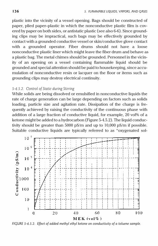
plastic into the vicinity of a vessel opening. Bags should be constructed ofpaper, plied paper–plastic in which the nonconductive plastic film is cov-ered by paper on both sides, or antistatic plastic (see also 6-6). Since ground-ing clips may be impractical, such bags may be effectively grounded bycontact with a grounded conductive vessel or skin/conductive glove contact
a grounded operator. Fiber drums should not have a loose
a plastic bag. The metal chimes should be grounded. Personnel in the vicin-ity of an opening on a vessel containing flammable liquid should begrounded and special attention should be paid to housekeeping, since accu-mulation of nonconductive resin or lacquer on the floor or items such asgrounding clips may destroy electrical continuity.
5-4.5.2. Control of Static during StirringWhile solids are being dissolved or emulsified in nonconductive liquids therate of charge generation can be large depending on factors such as solidsloading, particle size and agitation rate. Dissipation of the charge is fre-quently achieved by raising the conductivity of the continuous phase withaddition of a large fraction of conductive liquid, for example, 20 vol% of aketone might be added to a hydrocarbon (Figure 5-4.5.2). The liquid conduc-tivity should be greater than 5000 pS/m and up to 10,000 pS/m if possible.Suitable conductive liquids are typically referred to as “oxygenated sol-
136 5. FLAMMABLE LIQUIDS, VAPORS, AND GASES
FIGURE 5-4.5.2. Effect of added methyl ethyl ketone on conductivity of a toluene sample.
withnonconductive plastic liner which might leave the fiber drum and behave as
vents.” Note that esters may be “semiconductive” and less effective thanalcohols or ketones. Changes in flammability hazard of the resulting mixturemust be evaluated. For example, the addition of MEK to xylene may greatlyincrease the ignition hazard owing to the lowering of flash point. An alterna-tive method of increasing conductivity is to use a few ppm of antistatic addi-tive, which has no effect on flash point. This approach may requireconductivity evaluation in the process to ensure that the additive is notremoved by suspended or emulsified solids. The process change may alsorequire reapproval of the product by regulatory agencies. Metal-free antista-tic additives are discussed in 5-2.6. Although ignition hazards can alterna-tively be controlled by inerting, charge accumulation may result in “pinhole”lining damage to equipment such as enamel or glass-lined reactors (5-4.4.1).
5-4.6. Vacuum Trucks
Under vacuum conditions the flash point of liquid in the cargo tank isreduced (5-1.1.3) although vapor accumulation in the truck tank is offset byair throughput. Single component volatile liquids having a vapor pressureexceeding about 80 mmHg at 20°C should not be picked up using a vacuumtruck because they might boil, creating downwind air pollution and possiblya vapor cloud hazard. Boiling is an obvious hazard for Class 1A liquids buthas also been found to be a problem for Class 1B liquids, the more volatile ofwhich (such as acetone) may be substantially lost by evaporation. In thecase of mixtures, the listed vapor pressure may be due to components repre-senting only a small fraction of the bulk liquid and a small amount of boilingmay be acceptable provided the vapors are discharged to a safe location;also, the more volatile fractions may have weathered off by the time pick-upis scheduled.
Most “static” incidents appear to have been due to improper hose selec-tion and fires/explosions typically do not involve cargo tanks. Two mitigatingfactors during vacuum truck loading result from the low pressure inside thecargo tank, which can run as low as 50–80 mmHg. The first is that gas MIEincreases as pressure decreases (Figure 5-1.4b). The MIE of a typicalaliphatic hydrocarbon at pressures less than 0.2 atm (150 mmHg) exceedsthe effective energy of brush discharges. Therefore, while loading flamma-ble liquids, there is unlikely to be any static ignition source inside the cargotank provided all metal components are properly bonded together. Also,small metal items that are inadvertently sucked up should have too small acapacitance to cause ignition. Low MIE vapors such as carbon disulfide maybe exceptions since a fire was reported involving a carbon disulfide–water
5. FLAMMABLE LIQUIDS, VAPORS, AND GASES 137
emulsion. The second mitigating factor is the small overpressure that willresult even if a deflagration does occur during loading. If a typical maximum9:1 pressure ratio is developed, the maximum pressure starting at 80 mmHgwill be roughly the same as the ambient pressure outside the tank. Owing tothese mitigating factors plus practical considerations, flow rates do not needto be restricted to those recommended for road tanker operations (5-4.6.1).
Hoses must be chemically compatible with all materials that may bepicked up. For static control, hoses should be conductive or semiconductiveso that metal wands and hose connectors are bonded to the grounded truckvia the hose. For grounding requirements see 5-3.3.1. In no case should plas-tic wands be used. If a metal clamp is used to hold a wand in place it shouldbe bonded or otherwise electrically continuous with the grounded hose. Adrum explosion due to the use of a plastic dip tube and connected rubberhose is described in [8]. A conductive hose should preferably be a 100% flex-ible metal type. An alternative is to select a semiconductive hose so that lossof continuity in a bonding spiral does not isolate a wand or create sparksources along the hose (5-3.3.1). However, owing to the possibility of suck-ing up abrasive solids a thin semiconductive hose lining might be unsuitable.Where practical, the truck should be grounded either by bonding togrounded equipment or via a grounding rod (4-1.5). A fire in a toluene sumpwas caused by a spark from a spiral-wound conductive hose which pene-trated about 2 mm of rubber hose material to the metal rim of the sump;although the spiral was bonded to the truck, the latter was not grounded[33]. Ideally, the electrical continuity or individual grounding of all conduc-tive components (truck tank, conductive hose, metal connectors, wand,containers being emptied) should be established by test. During loading oroffloading flammable materials, personnel should not stand in front of orbehind rear open-dome type trucks. These are designed so that the rear ofthe truck tank is the weak point and this may act as a relief vent if deflagra-tion occurs inside the truck. Personnel wearing conductive or antistaticgloves will normally be grounded via the metal wand, but special consider-ation should be given to personnel grounding where vacuuming is donefrom opened equipment or other confined area where flammable atmo-spheres may rapidly accumulate.
5-4.6.1. Additional Precautions and AlternativesSome liquids might create an ignitable froth layer (5-1.3.1), although mistaccumulation will be offset under conditions where there is periodic suctionof air through the hose. It is possible to specify a vacuum truck tank withMAWP > 50 psig, sufficient to contain a deflagration beginning at up to
138 5. FLAMMABLE LIQUIDS, VAPORS, AND GASES
atmospheric pressure. This will not necessarily prevent hazards due to flameor hot gas venting from the tank vent or via the hose, but will prevent explo-sion of the truck tank.
Where “flammable” liquid spills (5-1.1) are to be collected, the use of asuitable pump (diaphragm or gear pump) and tank truck might be consid-ered as an alternative to the vacuum truck. This allows better control of oper-ational variables; where nonconductive flammable liquids are to be pickedup, excessive flow velocity, and the presence of a second phase such asundissolved water or entrained air can all lead to high rates of charging in thehose. Pumping to “rear open dome” vacuum trucks should be avoided sinceowing to the large dome area, even a small positive pressure in the cargotank can cause the latches to fail. Another alternative to direct loading to thecargo tank of a vacuum truck is a cyclone separator attachment which loadsto steel drums. Drums and associated conductive equipment should all beelectrically bonded to the grounded truck.
At the time of writing, API Publication 2219 “Safe Operation of VacuumTrucks in Petroleum Service” was in preparation.
5-4.7. Plastic Tanks
For portable tanks see 5-7. Where possible nonconductive plastic tanks
5-4.7.1. General Mitigation MeasuresThe use of fixed plastic tanks is especially problematic for nonconductiveflammable liquids because the efficiency of grounding aids (such as a con-ductive dip pipe or a submerged grounded metal plate) decreases as liquid
5. FLAMMABLE LIQUIDS, VAPORS, AND GASES 139
should be avoided for flammable liquids. Unburied plastic tanks presentexternal ignition risks if their outer surfaces become charged. Also there is noFaraday cage shielding of internal flammable vapors from the effects of light-ning as in the case of metal tanks. Where lightning and other risks are un-
remedy is to use a plastic tank that has a grounded, conductive mesh buriedacceptable a lined metal tank should be considered. An intermediate
in all external tank walls, although this might not be adequate for directlghtning strikes. In 1997, a plastic tank containing HCl accumulated ahydrogen-air atmosphere which ignited during an electrical storm, causing
From inspection of tank heat damage, a direct lightning strike to the tankthe tank to travel 300 ft. laterally and to reach an elevation of about 250 ft.
probably did not occur. However, a lightning strike map (using theNational Lightning Detection Network) showing probable strike zones dur-ing the storm indicated several strikes whose 97% confidence ellpses included the tank.
conductivity decreases. At very low conductivities of around 1 pS/m or lesssuch measures may become less effective owing to the slow rate of chargemigration to the grounding system. Also, since charged liquid inside tanksmay induce charge on conductive objects either inside or outside the tank,inerting will not remove external ignition hazards from the area. Where plas-tic tanks must be used for such liquids, careful attention to grounding aroundthe tank should be carried out and inerting should be used where possible.
Where plastic tanks are used for conductive or semiconductive liquidsin the presence of flammable gases, bottom filling using a conductive dippipe will greatly assist charge relaxation inside the tank. A slow start (5-3.4)should be used until the dip pipe is submerged. A slow start can be avoidedusing an internal grounding plate on the tank floor (5-4.7.2). Where corrosiveliquids such as acids are involved it is important to consider long-term com-patibility with the grounding system. An explosion of a waste acid tankoccurred after a broken dip pipe caused splash filling, which in turn led tostatic accumulation in the tank and a spark which ignited hydrogen gas. Inthis case the potential for hydrogen generation was previously unrecog-nized. Following the event the cause was immediately obvious and a quali-tative hazard analysis should have prevented the incident.
5-4.7.2. Use of Internal Grounding PlatesIt was theorized that the charge flowing into a plastic tank resting on theground, or other external grounded surface, would predominantly reside inthe capacitor formed across the tank floor [173]. In the absence of large con-ductive surfaces external to the tank sidewalls, their capacitances would besmall compared with the floor and only a small fraction of the total chargeflowing to the tank would reside there. It followed that a sufficiently largegrounded plate situated on the tank floor should be effective in dissipatingcharge even though only a small fraction of the internal wall area would begrounded. Tests were conducted using a 12 m3 fiber-reinforced polyester(FRP) tank having a 2´ 2 m floor area. A 1.0 ´ 0.5 m steel plate or heavysteel mesh was found to be capable of removing a large fraction of thecharge from flowing low-sulfur diesel oil having a conductivity of about20 pS/m. The oil was charged using a high voltage diode injector device. Forcharge densities of up to 185 mC/m3 and flow rates up to about 300 gpm, thecurrent collected by the plate or mesh at a given liquid depth was directlyproportional to the current flowing to the tank. Observed current collectionefficiencies were 30–70% during filling. The highest values occurred at smallliquid depths (about 0.4 m) prior to submergence of the side-entry fillingpipe. After complete submergence of the filling pipe at about 1 m depth, the
140 5. FLAMMABLE LIQUIDS, VAPORS, AND GASES
collection efficiency was about 50%. The efficiency gradually decreased atlarger depths due to the increasing capacitive effects of countercharges on theexternal tank walls [206]. The basic experimental arrangement plus a discus-sion of finite element computer modeling of the results is given in [174].
For flat-bottomed plastic tanks resting on the ground the plate or meshcan be placed directly beneath, and bonded directly to, the grounded metaldip pipe. However, the distribution of charge in an isolated plastic tankdepends on the relative location of all external conducting objects, not onlythe ground. Where a plastic tank is elevated and significant capacitance dueto adjacent conductors appears at side walls, the use of additional ground-ing plates on the walls concerned might be considered. The effect of wallcapacitance is most severe if the tank is equipped with a grounded, conduc-tive grid buried in the side walls. However, this is only of importance regard-ing internal grounding measures and the principal effect of such grids isbeneficial. The grounded grid is a barrier to electric fields, so that chargeinside the tank cannot cause hazardous induction outside the tank.
Exxon carried out test work in a horizontal, cylindrical FRP tank roughly3.1 m long and 1.2 m diameter [207]. Tank volume was 3.6 m3 (nominally 1000gallon). Kerosene jet fuel with a conductivity of 6–15 pS/m was charged usinga microfilter and flowed into the tank via a 3-in. metal pipe positioned 0.6 mfrom one end. It was found that 50–90% of the current generated in the filterwas removed by the fill pipe assembly, although external discharges occurredfrequently to conductive objects around the outside of the tank. Two sizes ofgrounded plate (25 ´ 90 cm and 25 ´ 168 cm) on the tank floor were thentested. It was found that essentially all of the generated current was collectedby the fill pipe plus plate. The outside of the tank was then completely coveredwith metal foil to simulate the effect of a buried, conductive grid in the tankwalls. Such a grid prevents external discharges but maximizes the effect ofwall capacitance. Most of the incoming current flowed to the walls, as indi-cated by the flow of countercharge to the external foil. The currents flowing tothe filling pipe, foil and grounded plate were compared as fractions of the cur-rent generated by the filter. It was found that the external foil reduced the cur-rent collected by the fill pipe and plates to 50–65%, with the larger plateshowing slightly greater charge removal. The charge attracted to the wallsslowly decayed over a period of the order 1 h. However, static discharges fromthe liquid surface ceased to be produced a few minutes after filling the tank.The tests showed that grounding plates are effective for plain tanks, tanks withgrounded metal grids in the walls and (by inference) buried tanks.
Based directly on conclusions given in the Exxon study [207], API 2003[3] recommends that the area of metal grounding plates should be not less
5. FLAMMABLE LIQUIDS, VAPORS, AND GASES 141
than 30 in.2 per 100 gallons or 500 cm2/m3. BS 5958 [2] recommends that fortank volumes up to 5 m3, the plate area should be 400 cm2/m3 and that theliquid should at no point be more than 2 m from the grounded plate. Thelanguage in BS 5958 implies that the tank volume and liquid distance restric-tions are simply cautionary statements based on the size limits of experi-mental tests.
5-5. Sampling, Gauging, and Analysis
For all manual operations see 4-3.1 “Personnel Grounding.”
5-5.1. Sample Container Cord
Grounded stainless steel cord or its equivalent is recommended for sam-pling and gauging operations. Chains are not electrically continuous andshould not be used in flammable atmospheres owing to possible creation ofspark gaps. Cord made from synthetic material or cellulosic fiber has the dis-advantages that (1) it does not allow proper bonding of conductive samplecontainers and (2) there is a possibility of charging if the cord slips rapidlythrough gloved hands. Although natural cellulosic fiber cord will not chargesignificantly via the second mechanism and should in principle give a smallenough RC time constant [Eq. (2-3.8)] to allow charge to dissipate from asample container, commercial cellulosic cord is frequently composed of anatural– synthetic mix. In practice the risk of static discharges from charged,nonconductive cord is low unless ignition sensitive gases such as hydrogenare present. Tests using charged plastic tubes showed that the ignition prob-ability of atmospheres having a MIE above 0.17 mJ only becomes negligiblefor tube diameters 5 mm or less [26], suggesting that a greater and usuallyunrecognized risk is due to nonconductive gas sampling tubes that are rap-idly lowered into tanks through gloved hands. Antistatic tubing is availablefor these applications (5-5.4).
5-5.2. Sampling
Sample containers are discussed in 5-8.4.2. For tanks containing a flamma-ble atmosphere this is most safely accomplished using a sampling well, alsoknown as a gauge well. This is a metal pipe, sometimes perforated, throughwhich a sample container or gauging device is lowered into the liquid. Themetal pipe is permanently fixed and electrically bonded to the top and
142 5. FLAMMABLE LIQUIDS, VAPORS, AND GASES

bottom of the tank. Since the pipe acts as a Faraday cage, the sample con-tainer cannot intensify the electric field inside the tank and create static dis-charges. Sampling can therefore be done at any time. Where sampling wellsare not used, sample containers should not be lowered into tanks while anyenergy is being added to the liquid, such as by pumping. Unless a samplingwell is used, a wait time should be allowed for charge to dissipate (5-4). Forstationary nonconductive liquids in large fixed tanks and ship compartmentsthe wait time should be at least 30 min for nonconductive liquids and at least10 min for semiconductive liquids. Shorter wait times are adequate for roadtankers and rail cars (5-4.2). Since charged mist may persist in the tank longafter charge has relaxed from the liquid, even conductive liquids mayrequire a wait time if splash-filling or other mist-generating factor is present.The sample thief, or other device such as a sample bottle cage, should bebonded to the grounded tank or other established grounding point. Whereatmospheres contain ignition sensitive gases such as hydrogen, metal com-binations capable of producing Galvanic sparks, such as copper wire on agalvanized steel tank, should be avoided.
Manual sampling should be carried out by grounded personnel, prefera-bly using grounded metal equipment such as a metal sample thief bonded tothe tank via metal cord. A satisfactory alternative is to place one or moreglass sample bottles in a grounded metal cage (5-8.4.2).
5-5.3. Gauging
An option is to use noncontact ultrasonic gauges, or electromagnetic radia-tion devices such as radar gauges, avoiding moving parts and possible loss ofelectrical continuity. Electronic gauges with data-averaging features can beespecially useful where the liquid surface sloshes around, as in ships’ tanksor stirred tanks. Gauge wells (5-5.2) are recommended for manual gaugingoperations; if these are unavailable an alternative to retrofitting is to use await time equal to that used for sampling (5-5.2). Manual gauging should becarried out by grounded personnel using grounded metal equipment.
Flotation devices for automatic gauge tapes should be antistatic or con-ductive with electrical continuity via the tape device to a proper ground. Iso-lated conductive components must be avoided. Consideration was given topossible ignition hazards of automatic tank gauges comprising a conductivefloat held between two grounded metal guide wires and suspended by aperforated metal gauge tape [47]. It was concluded that properly con-structed and maintained devices are unlikely to lose ground continuity and,further, the grounded metal guide wires greatly depress the electric fieldacting on the float.
5. FLAMMABLE LIQUIDS, VAPORS, AND GASES 143
5-5.4. Portable Flammable Gas Analyzers
Even if the device has been properly calibrated for the particular gas in air,some analyzers such as catalytic bead types will not function in oxygen defi-cient atmospheres containing less than about 10 vol% oxygen. Some porta-ble analyzers are supplied with antistatic tubing but others are supplied withnonconductive tubing such as Tygon.
If a metal wand plus a short length of tubing is used for manual samplinginside tanks or other enclosures, the tubing should be antistatic or conduc-tive to avoid isolating the metal wand, and the analyzer should be eithergrounded or hand-held by a grounded operator. The hazard of long,nonconductive sample lines charged by slipping through gloved hands isanalogous to that of synthetic cord, except that owing to the larger typicaldiameter of sample tubing the ignition risk is greater (5-5.1). When samplinglarge tanks for gas-free status, it may be required to sample near the base ofthe tank. In this case it is especially important that if a metal object is used tocreate a plumb bob it is not isolated from ground by a nonconductive sampleline. In both these cases, antistatic or conductive sample tubing should beused; tubing approved by the American Bureau of Shipping and the US CoastGuard is commercially available. ABS/CG requirements are based on a“Safety of Life at Sea” (SOLAS) regulation calling for “Anti-Static, ElectricallyConductive” tubing. However, for portable analyzer applications the tubingdoes not need to be conductive. Antistatic tubing is sufficient to dissipatecharge accumulated on the tubing itself. When using antistatic tubing with amolded-in wire, the wire should be bonded to the analyzer and to any metalprobe (wand or plumb bob) inserted into a potentially flammable atmo-sphere.
5-6. Tank Cleaning
5-6.1. Water Washing
During rapid shear of water–air interfaces such as during spray washing, thinfilms and filaments are produced from the interfacial layer which coalesceto form fine mist. The interfacial layer contains a net charge owing to thepresence of ions, which in pure water are negatively charged (OH–) ionsheld by the preferential orientation of water dipoles at the surface. Fartherbeneath the interface, positive ions do not form a surface bound layer sincethey are thermally randomized, so coarser droplets formed from the body ofthe water jet carry a net positive charge. The coarser droplets settle out faster
144 5. FLAMMABLE LIQUIDS, VAPORS, AND GASES
leaving behind fine mist containing net negative charge [85]. As washingprogresses, a steady-state is eventually reached in which the mist tends toachieve a constant charge density, the rate of production being countered bymist removal and charge neutralization by corona. If salt water, detergents orother contaminants are present, the fine mist may instead be charged posi-tively owing to a reversal of the initial interfacial polarization. Hot and/or coldwashing cycles using portable or fixed washing equipment therefore resultsin a cloud of charged water droplets which creates an electric field insidethe tank. Hot washing creates higher charge densities and potentials thanthe cold wash.
5-6.1.1. Conductive TanksProvided all conductive components in the tank are grounded the onlysource of a static spark is charged, isolated slugs of water. These may formduring breakup of a jet, drainage from an overhanging tank component, orsloshing of water heels inside a vessel at sea. In the absence of steam, testwork and calculations (A-5-6.1) suggest significant hazards only occur intanks exceeding 1000 m3. Precautions for washing large tanks such asmarine center tanks are given in ISGOTT [5]. Analyses (A-5-6.1) suggest thatthe hazard can be neglected for tanks less than 100 m3, although more con-servative guidelines have been published for industrial tank applications[127] as noted below.
There is negligible “isolated water slug” hazard for barge tanks owing totheir size and geometry, provided steam is not injected directly to the tankduring any hot wash, for example during start-up of a steam assisted hotwash system [186]. Consideration might be given to a cold wash prior to hotwater washing, since this may in some cases reduce the flammable vaporconcentration with associated benefits in controlling air emissions.
Conservative guidelines for industrial tanks containing flammable atmo-spheres have been published by a group of four major European companies[127]. Washing is restricted to continuously drained metal or enameledmetal tanks having a volume no greater than 30 m3 (or diameter no greaterthan 3 m) with all conductive parts grounded. The sprayed water has a maxi-mum feed rate of 300 L/min and pressure does not exceed 500 bar. Theseguidelines are based on the assumption that incendive brush dischargesoccur in tanks where the breakdown field of air is exceeded at the groundedspray head, the latter being modeled as a 4-cm-diameter grounded elec-trode placed in the center of a charged cloud of droplets with a volumetriccharge density of 240 nC/m3. The requirement for a water slug is omitted.The tendency of wet surfaces to produce corona rather than brush dis-charges is not considered (A-5-6.1).
5. FLAMMABLE LIQUIDS, VAPORS, AND GASES 145
On June 3, 1998, in Rotterdam a 165-m3 cone roof tank containingmethyl tertiary butyl ether (MTBE) exploded while being washed, causing afatality and launching the 1.4 tonne roof a distance of 100 m. The tank was 10m high by 4.5 m diameter. Initially the tank contained 27% MTBE vapor withthe balance nitrogen. However, as washing proceeded a vacuum truck wasused to suck sludge, water, and residual MTBE out of the tank bottom. As thevacuum hose lost contact with the liquid layer, the resulting negative pres-sure intermittently sucked air into the tank via the top manway, which held ahigh pressure washing device. Turbulent mixing by the washing jets helpedform a flammable mixture in the tank. The explosion occurred during thefourth cleaning cycle and the fatally injured man was blown from the roofshortly after adjusting the washing device. Two “static” mechanisms consid-ered were a static discharge involving the water mist and a static dischargefrom an ungrounded vacuum hose. The latter would have to be ruled outbefore attributing this incident to a charged mist mechanism involving brushdischarges or charged water slugs. The company involved had previouslyventilated their tanks to the air to reduce flammable vapor concentrations toa safe level, but this approach had been abandoned owing to local emissionconstraints.
5-6.1.2. Nonconductive Plastic and Plastic Lined TanksWhere flammable gas/vapor is present or may be generated during cleaningit is recommended that these tanks be inerted. For example, a deflagrationoccurred during water washing of a lined internal floating roof tank and allcauses other than a spark from charged water in the tank were ruled out bythe oil company concerned. Where sensitive gases such as hydrogen maybe generated the risk of static ignition increases (5-6.4).
5-6.2. Solvent Washing
The charge densities of mists created by flammable and combustible sol-vents are similar to those from water washing and similar precautionsshould be taken regarding grounding of conductive components. Wherepossible the tank should be inerted. Since it is not usually possible to controlthe flammable atmosphere by operating below the LFL, solvent washingshould only be used in noninerted tanks if water washing with added clean-ing agents such as detergents, or water washing followed by steam cleaning,are not practical alternatives. If possible the solvent used should have a flashpoint above the maximum temperature expected for the operation (5-1.1.5).Although this will not prevent the formation of flammable mist in the tank
146 5. FLAMMABLE LIQUIDS, VAPORS, AND GASES
(5-1.3), it will be less hazardous than using a solvent that creates a continu-ously flammable vapor atmosphere (5-1.4.4). Solvents having flash pointsgreater than 200°F can often be used in these operations and in general thesolvent should be selected at least in part on the basis of high flash point.
If the solvent is nonconductive, additional precautions are needed.These are (1) continuous draining to prevent build-up of charged liquid inthe tank and (2) measures to avoid accumulation of solids if the solvent isrecirculated. Measures to separate solids before recirculation, such as filtra-tion, may increase static generation (5-3.5).
Expert review should be made of any procedure requiring personnel inthe tank during solvent cleaning operations. In 1998, a flash fire fatalityoccurred in England during manual cleaning of a tank using xylene at lessthan its flash point. The operation involved an ungrounded metal buckethanging in the tank from which xylene was taken with sponges. The wring-ing out of the sponges is believed to have charged the bucket which subse-quently sparked to the tank internals, igniting a mixture of xylene plus apreviously unrecognized but significant concentration of residual MEK vaporin the tank. The incident was especially serious as fire resistant clothing wasnot worn and a container of xylene was spilled during emergency egressfrom the tank.
Where inerting is not used, one guideline restricts operations to metal orenameled metal tanks having a volume no greater than 5 m3, a diameter nogreater than 3 m and all conductive parts grounded. The liquid should con-tain a maximum of 1 wt% insoluble solids, have a maximum feed rate of60 L/min and the delivery pressure should not exceed 50 bar. The vesselshould be continuously drained to prevent liquid accumulation [127].
5-6.3. Steam Cleaning
Steaming creates high charging currents in the hose, primarily as a result ofexpansion at the nozzle. All components of the steaming system must beconductive and grounded to prevent sparks. The expansion of wet steamalso produces a charged jet whose charge density depends on orifice geom-etry plus steam temperature and pressure. Ignition tests have been per-formed to address brush discharge hazards from steam jets. However, thesehave typically failed to demonstrate ignition even of stoichiometric hydro-gen–air mixtures [46, 85]. The mist created by steaming has a large chargedensity resulting in a correspondingly large space potential which increaseswith the diameter of the tank (A-5-6.1). Large fields and potentials mightresult in corona and brush discharges from tank internals or spark dis-
5. FLAMMABLE LIQUIDS, VAPORS, AND GASES 147
charges from isolated slugs of water. Although steam is usually a more effec-tive inerting gas than nitrogen, this is only true to the extent that the oxygenconcentration is reduced to less than the LOC. Credit cannot be taken forcondensed mist. Until the tank temperature exceeds 80°C, corresponding toa steam partial pressure ³0.47 bar, the residual concentration of oxygenderived from air can exceed 10%. Therefore, a flammable mixture may per-sist long into the steaming process.
As discussed in 5-6.1.1, a conservative guideline for water washing tankscontaining flammable atmospheres limits the maximum tank size to 30 m3.The basis for this provision is to avoid brush discharges at the washing head.If a similar analysis is carried out for steam cleaning, the maximum allow-able tank size will be smaller owing to the greater charge densities producedin steam mist. Recommended practices such as [1,2] limit the tank size to100 m3 instead. No rationale is given for this round number. In principle,steam cleaning should be most hazardous if charged slugs of condensateare ejected into a large, roughly cubic or squat cylindrical tank containing aneasily ignitable atmosphere. If there are no conductive water slugs and allmetal components are grounded, the only source of ignition during steam-ing is the brush discharge. There is no direct evidence that brush dischargesare a hazard during steaming although the probability of their occurrenceincreases with tank volume. The user should consider risk tolerance wheretanks up to 100 m3 are steamed while containing a flammable atmosphere.
Where steam cleaning of large tanks is carried out, gas freeing orinerting should be considered. Gases initially present in the tank can beremoved by ventilation or water displacement. During steaming, flammablevapors may be released from liquid heels or deposits. An option is to periodi-cally test for flammable vapor and either ventilate or (if the vapors are watersoluble) perform water washing until the vapor concentration is less than25% LFL. Alternatively, steaming may be carried out using inert gas to staybelow the LOC. Unless a tank is designed for vacuum, vent capacity must besufficient to prevent underpressure damage as steam condenses.
5-6.4. Acid Washing
These operations often generate hydrogen and other flammable gases.Hydrogen is commonly produced and is a special hazard owing to its verylow MIE, wide flammable range and fast burning velocity. Further, hydrogenflames can be practically invisible in daylight, creating an additional injuryhazard. Static has caused numerous explosions. In one case, a reactor con-taining a cobalt catalyst residue was cleaned and the acid wash was trans-
148 5. FLAMMABLE LIQUIDS, VAPORS, AND GASES
ferred to a polypropylene portable tank via a conductive hose. Hydrogen wasgenerated via acid–catalyst reaction. The portable tank was splash-filled,which allowed the waste liquid to accumulate static charge. When thecharged liquid surface reached the conductive hose hanging inside the por-table tank a spark was generated, igniting the hydrogen–air mixture. Anoperator was injured by the subsequent explosion. Hydrogen continued tobe generated in the reactor and burned for some time afterward as it exitedthe hose. Where possible these operations should be inerted (NFPA 69) andcareful attention should be paid to grounding. Plastic tanks and tanks withnonconductive linings require particular care since in the absence of a suit-able grounding system even very conductive liquids such as water or acidrinses can accumulate charge. Conductive liquids typically produce sparksinstead of brush discharges; hydrogen may be ignited by spark at a potentialas low as 100–300 V (Table A-1-4.1.3b). To put this in perspective, ignition ofgasoline vapor in air via brush discharge from a nonconductive liquidrequires a minimum surface potential of about 25,000 V (A-5-4).
5-6.5. Grit Blasting
Where possible tanks should be gas free or inerted. Conductive or semicon-ductive hose should be used and attention given to personnel groundingwhere flammable atmospheres might exist. All conductive components,especially the hose nozzle, should be grounded to avoid static sparks. In addi-tion to static hazards, the possibility of uncovering pyrophoric iron sulfidedeposits should be evaluated. It is highly improbable that ignitable dust cloudscan be produced as a direct result of using organic grit such as walnut shells.
5-7. Portable Tanks
As defined in NFPA 30 portable tanks have capacities above 60 gallons(227 L) and usually below 660 gallons (2498 L).
5-7.1. Metal Portable Tanks
Bottom filling should be used for nonconductive flammable liquids and fil-ters should be placed at least three relaxation times upstream (5-3.4 and5-3.5). The container should be grounded prior to opening and sealed priorto removing the grounding system. Filling rates should be similar to those
5. FLAMMABLE LIQUIDS, VAPORS, AND GASES 149
used for drumming (about 60 gpm or less) unless the container is inerted. Ifthe dip pipe does not extend close to the bottom and the vessel is notinerted, a slow start of 1 m/s or less should be used until the dip pipe is sub-merged to about 6 in. Conductive and semiconductive liquids present minorstatic hazards except during operations such as sampling and gaugingwhere equipment or operators in the vicinity of a tank opening are notgrounded. Tanks with nonconductive linings present hazards somewhatmore severe than the case of drums (5-8.2.2) owing to their larger volumesand hence larger potentials that may be generated for equal charge densi-ties.
5-7.2. Plastic Portable Tanks
See NFPA 30 for general restrictions. This category of tanks includes Inter-mediate Bulk Containers (IBCs) comprising plastic jugs within metal supportframes, and composite IBCs comprising plastic jugs independent from theirexternal metal shells. Although IBCs might be bottom-unloaded, avoidinghazards associated with manual insertion of unloading lines, manualremoval and replacement of vent caps should be carried out by groundedpersonnel. Attention should be given to ensuring safe handling of “empty”plastic jugs containing flammable vapor–air mixtures following unloading,including cleaning and/or disposal.
Tanks manufactured from nonconductive plastic should not be used forflammable liquids unless the tank is inerted prior to filling, and the operationis subject to expert hazard analysis. Such an analysis should include the eval-uation of emergency response both for a leak and an external fire. Highlycharged, nonconductive liquid might give rise to propagating brush dis-charges from the plastic in addition to brush discharges from either the plas-tic or liquid surface. Additional measures for liquids capable of generatingflammable vapor atmospheres might include inerting and personnelgrounding during unloading. A case history of an explosion in a plastic porta-ble container used for collecting an acid wash is given in 5-6.4.
5-8. Portable Containers Less Than 60 Gallons Capacity
Drums comprise metal, lined metal or plastic containers with capacity up to60 gallons (227 L) and are the largest containers considered in the followingsections. Metal and plastic-lined metal drums can have either fixed orremovable heads. It should always be ensured that drums are sealed prior to
150 5. FLAMMABLE LIQUIDS, VAPORS, AND GASES
handling and that when opened they are properly grounded. Since plasticdrums cannot be grounded they should not be used for flammable liquids orhandled in flammable atmospheres without expert review of the hazards.Although drum explosions due to static have low probability, the largenumber of operations means that incidents are not rare. Furthermore, theconsequences are often serious. Although the volume of a drum is relativelysmall, a flammable mixture that ignites via static is likely to be close to itsmost easily ignitable composition. The “most easily ignitable” mixture alsocreates the highest pressure when it deflagrates inside a drum. Static ignitioncan result in fire and/or explosion, with potential for impact injury. If a steeldrum fails at the bottom chime due to an internal explosion it can rocket fortens of feet, spilling its contents and creating a serious risk via mechanicalimpact and fire [8]. Missile hazards can result from detached drum headseven if the drum remains in place. As an example, an “open-head” drumcontaining MEK being rolled on its lower chime exploded and theclamped-on head detached, cutting off the operator’s nose. Although fulldetails were unavailable, it appeared that a spark from the operator ignitedMEK vapor in the vicinity of an opening in the drum head. For manual load-ing/unloading operations involving flammable vapor, it is recommendedthat personnel are grounded so they are not a source of ignition (4-3.1), andthe bungs and/or drum lid are tightly closed prior to moving the drum.
5-8.1. All-Steel Drums
a. Filling. See 4–1 for general grounding requirements. Drums should begrounded and bonded to associated conductive equipment such asweigh-scales and filling lances. Simple frictional contact between a fillingnozzle and the drum port might not give a satisfactory bond especially if aplastic bushing or paint layer is present at the drum port. Proper bond con-nections should be made using clamps capable of penetrating any paintlayers on the drum, typically screw types or spring clamps employing hard-ened metal points. Bond connections on the upper chime should be locatedaway from the drum ports prior to bung removal and the connections shouldnot be removed until the bungs have been replaced. Braided and uninsulat-ed stainless steel bonding cable is preferred. If insulated cable is used with-out a ground indicator, a broken cable can go unobserved betweenscheduled tests. Any filter in the filling line should be grounded and wherepossible placed at least three relaxation times upstream of the filling pipeoutlet unless the drum is inerted prior to filling. If neither option is practicalfor nonconductive liquids, the filter should be placed as far upstream as pos-
5. FLAMMABLE LIQUIDS, VAPORS, AND GASES 151
sible and reduced flow rates should be used [8]. For conductive liquidseither splash filling or bottom filling is acceptable. The filling rate fornoninerted drums should be such that the drum takes 1–2 min to fill (forexample, £30 gpm with a 1-in. filling pipe and £60 gpm with a 2-in. fillingpipe); as a reference, gasoline pumps typically dispense at 10–12 gpm. Fill-ing/emptying lances should be conductive and grounded, and when usedfor nonconductive liquids should preferably have pointed tips such as a 45degree cut to minimize the probability of a brush discharge [8]. Unlessinerting is used, automated filling devices should not be programmed to sus-pend blunt lances above nonconductive liquids as a solution to drippingfrom the wetted lance between fills, since this practice may result in brushdischarges from the liquid [8].
b. Dispensing. Pressurized gas should not be used to dispense liquid.Drums should be grounded and the use of a ground indicator, possibly inter-locked, should be considered for drums not dispensed from racks. For grav-ity dispensing from racks, drums should be fitted with spring loaded metalvalves which shut automatically when hand pressure is released. Each drumshould be equipped with a drum vent, typically at the larger bung; 2-in.dual-action safety drum vents incorporating a flame arrester are commer-cially available. Dispensing should normally be via the smaller (¾ in.) bungunless viscosity considerations do not allow this. Small conductive contain-ers such as cans should be bonded to the rack. For vertical dispensing, drumpumps and dip pipes should be conductive and grounded. The pump mustbe suitable for the service. For flammable liquids, plastic hand pumpsshould not be used and instead these should be of groundable metal con-struction. Hand pump designs incorporating an internal flame arrester arepreferred. Hoses should either be semiconductive or conductive andgrounded (5-3.3). To reduce vapor emission the dip pipe should fit closelyinto the 2-in. dispensing opening. As liquid is dispensed, air will be suckedinto the drum primarily through the vent opening. Use of a flame arrestermight be considered for drums used for occasional dispensing over a longperiod. If vacuum unloading is done, additional measures such as anti-siphon devices and pressure interlock with any inert gas supply might beneeded.
c. Cleaning. Drums should be grounded prior to opening for cleaning oper-ations such as steaming. Cleaning equipment should be grounded. Until cer-tified gas-free, drums should be assumed to contain flammable vapor andbe grounded unless closed. An explosion occurred while discharging steamvia ¼-in. nipples into an “empty” inverted styrene drum on a wooden plat-
152 5. FLAMMABLE LIQUIDS, VAPORS, AND GASES
form, tossing the drum 10 ft. in the air and causing a fire [31]. Even a new,unused drum might contain vapor following solvent wiping during manufac-ture and a drum explosion has been reported due to a label being weldedonto such a drum [8].
5-8.2. Plastic Lined Drums
Linings inside metal drums hinder the flow of charge to the grounded metalshell and present a more hazardous case than all-steel drums; in principle,even conductive liquids can accumulate charge. However, the lining has arelatively large capacitance which provides considerable mitigation com-pared with an all-plastic drum. If the lining is assumed to be a perfect insula-tor over the timescale of loading, and the liquid is splash-filled so no chargeis lost via a dip pipe, the charge must flow to the insulated wall and residethere forming one plate of a large capacitor. The external grounded drumwall provides the other capacitor plate. Given the reasonable assumptionthat most of the charge migrates from the bulk liquid to its surfaces, the sur-face potential of the liquid in the drum V is approximately equal to QT /C,where QT is the total charge and C the capacitance of the floor and the walls.The equilibrium potential V at any time is directly proportional to the chargedensity entering the drum QV and the thickness a of the lining [8]
V = QVFtab/[ere0(pb3 + 2Ft)] (5-8.2)
where F = volume flow rate (m3/s), t = elapsed filling time (s), andb = drum radius (m)
Static effects of thin internal coatings such as phenolic paints can beneglected even if they are applied so that there are no pinholes. Theirresistivities are orders of magnitude less than polyolefin lining materials, plusthe coatings are typically so thin (0.5–1 mil) that the associated high capaci-tance and small breakdown voltage prevents large surface potentials frombeing attained (5-4.1.3). Liquid surface potentials of 10–15 kV were devel-oped when nonconductive kerosene was charged to about 570 mC/m3 by abag filter and directly splash-filled into “poly steel” drums containing moldedpolyethylene liners 1.8–2.8 mm thick [8]. This is less than the thresholdpotential for incendive brush discharges. However, since sparks from moreconductive liquids can be incendive above about 1 kV it is recommendedthat bottom filling using a grounded metal dip-pipe be used for all drumscontaining molded nonconductive liners. Drum grounding requirementsand filling rates are otherwise the same as for all-steel drums.
5. FLAMMABLE LIQUIDS, VAPORS, AND GASES 153
The probability of a propagating brush discharge (PBD) in a plastic lineddrum is negligible. A typical 55 gallon drum has a diameter of 0.572 m andfilled height of 0.811 m, so the wetted area is 1.71 m2. In order for a PBD tooccur, a minimum surface charge density of 2.5 × 10⁻⁴ C/m2 is required(2-6.5) corresponding to a total charge of 4.29 × 10⁻⁴ C over the internaldrum area. If the drum is splash-filled and the liner is a perfect insulator, sothat no charge can dissipate, the liquid entering the drum would require avolume charge density of 2060 mC/m3. Such a large charge density is notcredible unless the drum is splash-filled directly from a filter, disregardingrecommendations concerning dip-pipes and filter placement. Additionalmitigating factors are that PBDs are only an ignition hazard above the liquidsurface and the assumed PBD charge density threshold of 2.5 × 10⁻⁴ C/m2 isprobably conservative (2-6.2.3).
5-8.3. Plastic Drums
See NFPA 30 for storage restrictions. Since plastic drums cannot begrounded they pose inherent static hazards in flammable atmospheres. Theuse of plastic drums for Class I flammable liquids is discouraged and thisshould be considered only in special cases where plastic is essential forquality purposes, such as an intolerance for metal contamination. Wheresuch a case is identified, expert review of the hazards is recommended.Although drums could be inerted prior to loading or filled at a temperatureless than the liquid flash point, similar precautions are more difficult to applyto the unloading operation. If the operation is not under the control of thesupplier, for example at a customer site, it is difficult to enforce recommen-dations from the expert hazard review. For Class II combustible liquids,static should be addressed where (1) the liquid may exceed its flash pointduring filling or emptying or, (2) the drum could be stored or handled in aflammable vapor atmosphere. In case 1, options include bottom filling andcool-down provisions prior to unloading, especially if the drum has been indirect sunlight or in a hot storage area. In case 2, plastic drums should wherepossible be stored away from drums containing flammable liquids so thatthe ignition hazard of discharges from the external drum surfaces is avoided(Figure 5-8.4b).
5-8.4. Hand-Held Containers
The fire risk from static ignition increases with the volume and volatility offlammable liquid handled. Hence, the smallest volume container capable of
154 5. FLAMMABLE LIQUIDS, VAPORS, AND GASES
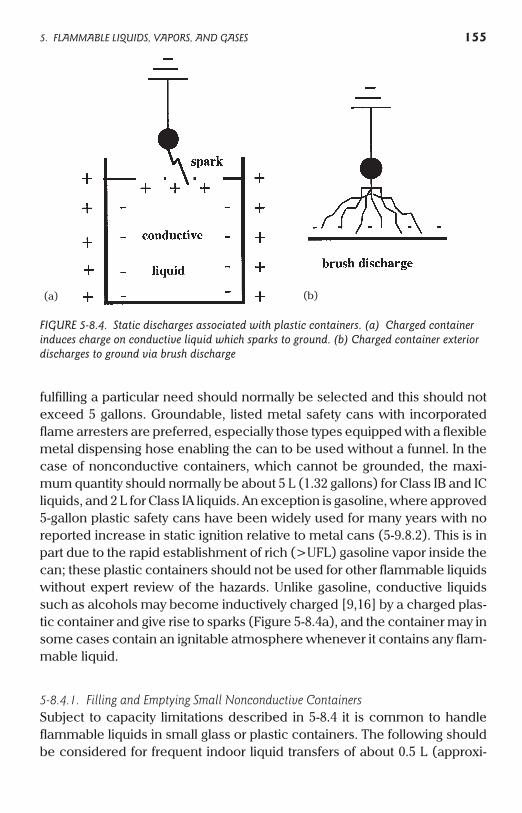
fulfilling a particular need should normally be selected and this should notexceed 5 gallons. Groundable, listed metal safety cans with incorporatedflame arresters are preferred, especially those types equipped with a flexiblemetal dispensing hose enabling the can to be used without a funnel. In thecase of nonconductive containers, which cannot be grounded, the maxi-mum quantity should normally be about 5 L (1.32 gallons) for Class IB and ICliquids, and 2 L for Class IA liquids. An exception is gasoline, where approved5-gallon plastic safety cans have been widely used for many years with noreported increase in static ignition relative to metal cans (5-9.8.2). This is inpart due to the rapid establishment of rich (>UFL) gasoline vapor inside thecan; these plastic containers should not be used for other flammable liquidswithout expert review of the hazards. Unlike gasoline, conductive liquidssuch as alcohols may become inductively charged [9,16] by a charged plas-tic container and give rise to sparks (Figure 5-8.4a), and the container may insome cases contain an ignitable atmosphere whenever it contains any flam-mable liquid.
5-8.4.1. Filling and Emptying Small Nonconductive ContainersSubject to capacity limitations described in 5-8.4 it is common to handleflammable liquids in small glass or plastic containers. The following shouldbe considered for frequent indoor liquid transfers of about 0.5 L (approxi-
5. FLAMMABLE LIQUIDS, VAPORS, AND GASES 155
FIGURE 5-8.4. Static discharges associated with plastic containers. (a) Charged containerinduces charge on conductive liquid which sparks to ground. (b) Charged container exteriordischarges to ground via brush discharge
(b)(a)
mately 1 pint) or more, such as a small-scale solvent blending operation.Where possible the operation should be conducted in a well ventilated areasuch as a hood, using a grounded metal catch tray capable of containing theentire inventory of liquid. When filling a container, a grounded metal funnelwhose spout extends to the bottom of the container is preferred. Thisensures that if charge is induced on the liquid by a previously charged con-tainer (Figure 5-8.4a), it will flow to ground via the immersed funnel insteadof sparking to the funnel as the liquid level rises. Plastic or glass funnelsshould be used only where essential for compatibility reasons. Personnelshould be grounded.
5-8.4.2. Containers for SamplingIgnition risk is greatly increased when a flammable atmosphere is presentoutside the small container, for example when sampling directly from a tankor transferring a sample near a manway, since this might precipitate a largefire or explosion. A grounded metal sample thief, or glass bottle in agrounded metal sample cage (5-5) might be selected in such cases.
ventilated areas, since they are more easily charged than glass and numer-ous incidents can be traced to their use. In general they should not be carriedin coat pockets or otherwise wrapped in fabric since upon withdrawal alarge surface charge can be placed on the bottle. This can cause inductioncharging and possible ignition when sampling a conductive liquid. Toaddress breakage concerns, alternatives to glass bottles include antistaticplastic bottles and plastic coated glass bottles. In the latter case the plasticcoating should be antistatic, which may well be the case owing to the largequantity of plasticizer normally required for PVC coatings. If outdoor sam-pling is carried out at sample spigots away from tank openings and in freelyventilated areas, and sampled quantities are 1 L (1 qt.) or less, the fire risk isinsufficient to require any special procedures other than ensuring that agrounded metal dip tube, extending close to the bottom of the container, isused for filling.
In a demonstration experiment the author placed about 1 in. of water ina 1 pint glass bottle. After drying the outside of the bottle using warm air itwas rubbed with a dry paper towel. An induced voltage of 3 kV was mea-sured on the water using a field-mill voltmeter, whose shared capacitancecaused roughly a factor-of-two underestimation of the maximum voltage(3-4.1). Glass bottles are relatively difficult to charge by rubbing unless thehumidity is very low. It is far easier for plastic bottles to become charged andinduce hazardous voltages on conductive liquids inside them.
156 5. FLAMMABLE LIQUIDS, VAPORS, AND GASES
Nonconductive plastic bottles should be avoided except where used in well
In 1985, ethylene oxide (EO) ignited in a 1 pint “clip top” glass samplebottle during sampling from a tank car. The ¼-in. stainless steel liquidsample line from the car entered a sampling hood and EO flowed at rela-tively high velocity (4 m/s) into the bottle through a Teflon tube. The Teflontube was used to prevent water condensation on the cold sample line, sinceif water dripped into the sample bottle it would affect turbidity evaluation.EO has a very small ignition energy in air and it was not possible to absolutelyrule out ignition by a charged operator. Plausible mechanisms involved (1)EO charging during flow through the Teflon tube, or (2) induced charge onEO liquid from an externally charged sample bottle, or (3) induced chargingof the wire clip on the bottle stopper by charged Teflon tube. All of thesemechanisms could be avoided by bottom filling with a grounded stainlesssteel dip tube. The water condensation problem was avoided by fitting thedip tube with a thermally insulating Teflon sleeve, leaving a few millimetersof exposed metal at the outlet. Subsequent to this fire, operators weregrounded using wrist bracelets.
5-8.5. Wet-Dry Vacuum Cleaners
If used for flammable liquid spills, which might involve a second phase suchas spill control granules or debris, these pose numerous design problemsincluding static, electrical classification, chemical compatibility and indus-trial hygiene relative to the exhaust. Commercial designs for Class I Group Dgas and Class II Groups E-G dust atmospheres are typically air operated via aventuri, so contain no electrical drives. Hoses both for air supply from agrounded air supply outlet, and for liquid recovery, are conductive with addi-tionally static dissipative hose fabric (about 105 W-m). Filters are also staticdissipative. The design is such that all parts are continuously bonded andgrounded. Normally the ground continuity is established at prescribed checkpoints before each use. Float or similar mechanisms are employed to cut offsuction once the recovery tank has reached capacity level, although addi-tional precautions may be needed to avoid overflow via either siphoning (ifthe recovery hose is completely submerged in liquid) or if defoaming agentsare not used where appropriate. For flammable liquid spills in particular, mea-sures should be taken to ensure personnel are not a source of ignition (4-3.1).
5-9. Miscellaneous Flammable Atmospheres
5-9.1. Clean Rooms
For health care facilities see NFPA 99. Clean rooms require superior staticcontrol measures where flammable liquids are handled. Smoke may be
5. FLAMMABLE LIQUIDS, VAPORS, AND GASES 157
intolerable for quality reasons even if a fire is minor. The relative humidity inclean rooms is often controlled at a low value which can decrease the resis-tivity of surfaces and hence increase static accumulation. Grounded metalsafety cans and steel cabinet storage are recommended, taking care to mini-mize the quantity of flammable liquid in the clean area. Measures includeantistatic floors and personnel grounding, including the use of antistatic labcoats. It should be ensured that floor grounding is not compromised by anynonconductive film either from operations or cleaning agents such as floorwax. Careful attention to equipment grounding is required. Plastic equip-ment should be avoided wherever possible and even small metal transfercontainers should be grounded. Items such as cartridge filters require spe-cial attention during replacement and if possible the casing should bepurged until the element is dry. Disposal of solvent-wet material such as filterelements and towels should be via conductive containers. Such containersshould be grounded when in the clean area and sealed before removal. Ifplastic disposal bags are used they should be conductive or antistatic. Tearsheets generate significant static when they are taken up (5-9.5).
5-9.2. Water and Steam Curtains
These do not pose a recognized static hazard if the curtain device and allequipment that could be electrically charged during operation is bondedand grounded [45,46].
5-9.3. Static Electrification in Gas Flow
The presence of solids such as pipe scale, or suspended liquids such aswater or condensate, creates charged particles carried by the gas phase.Condensate may be created by sudden cooling or expansion of gas throughan orifice. An example is sudden release of a pressurized hydrocarbon.Impact of the charged stream on ungrounded objects can create spark haz-ards. A special case is carbon dioxide, which when discharged under pres-sure will form charged solid “snow.” This can create an ignition hazard ifsudden discharge of carbon dioxide is used to inert flammable atmo-spheres. Static ignition is not a problem with portable carbon dioxideextinguishers used to put out fires. However in some fixed nozzle systems anew flame front could in principle be initiated remote from a flame sensorlocation, compromising the “barrier” effect of a flame suppression system.Distribution nozzle designs are discussed in [52].
158 5. FLAMMABLE LIQUIDS, VAPORS, AND GASES
In some cases, gas flow rates are restricted to avoid mechanical ignitionvia adiabatic compression and frictional impact of small particles with sur-faces; examples include oxygen and acetylene. In oxygen systems, ignitionassociated with particle impact is especially likely just downstream of a loca-
at velocities above about 50 m/s. Usually there is negligible static generation
react at pipe walls producing an accumulation of dihydrogen cations in theboundary layer, which react rapidly with neutral molecules to give activeradical-initiated combustion [43]. This rather speculative mechanism is yetanother possible factor in otherwise unexplained ignitions of hydrogenduring venting (5-9.4). It is sometimes stated that hydrogen vent ignitions arecaused by the inverse Joule–Thomson effect as the gas expands. This isincorrect and calculations show that at 38°C the temperature increase is onlyabout 5°C for an atmospheric release at an initial pressure of 210 bar [212].Hydrogen and syngas ignition in air might alternatively be explained by shockeffects or entrainment of finely divided, reduced metal oxides, which can bepyrophoric in air. These gases typically ignite when they are vented or leak atpressures above a few hundred pounds per square inch, although the expla-nation is unclear (5-9.4).
5-9.4. Ignition of Vented Gas
Gases with very low ignition energies (such as acetylene and hydrogen) con-taining suspended material might be ignited by corona-brush dischargeswhen escaping from stacks at high velocity. This phenomenon is associatedwith electrical breakdown at the periphery of the charged dust stream beingvented, although as noted in 5-9.3, mechanical ignition via friction or com-pression might occur if air is present in the vent pipe. Static discharges atvent outlets can occur even if the equipment is properly grounded. Atmo-spheric electricity might also cause “spontaneous” vent fires since thebreakdown field of some gases (such as hydrogen) is less than that of air.Hence, the presence of the gas enables atmospheric electric fields to causegas breakdown and static discharges at lower values than would berequired in air. The discharge may be corona-brush type or an upwardstreamer from the stack that fails to connect with a stepped leader from athundercloud. Atmospheric electricity can be sufficient to cause static dis-charges from elevated vents such as stacks even where lightning is notobserved locally. Mitigating measures for stacks have consisted of two oppo-site approaches. In the first (possibly obsolete) method the stack is designed
5. FLAMMABLE LIQUIDS, VAPORS, AND GASES 159
in single phase gas flow, although flowing hydrogen has been postulated to
tion where there is at least a 2:1 absolute pressure drop, and may occur
to prevent discharges by using surfaces having large radius of curvature; in[135] a doughnut-like device (“NASA toroidal ring”) is discussed for place-ment on the top of the stack. In the second, the stack is designed to encour-age corona discharges by using sharp edges and/or commercially availablelightning protection equipment. Where stacks cannot be vented tocombustors or flares, they should be equipped with snuffing devices to blowout the flame. Nitrogen or steam at mass fractions above about 0.3 can beused for acetylene, while helium is often preferred for hydrogen vent fires.Snuffing is particularly important for acetylene, which can slowly burn downthe stack and, additionally, through any metal flame arrester in the base ofthe stack. Alternatively, a burn pond can be used to safely dispose of largevented quantities of hydrogen. Other mitigation is discussed in [157].
5-9.4.1. Ball Valve Stem LeaksThe packing in some designs of ball valve can isolate the valve stem orhandle from the valve body (5-3.7). Packing leaks may result in ignition viasparks from charged, isolated metal. A particular example is ignition of acet-ylene. Ball valves are frequently used in acetylene service owing to the seal-ing action of the packing should a deflagration occur in the line; other typesof valve may be sufficiently distorted by the pressure transient to allow flamepropagation past the valve even when fully shut. It should be ensured thatball valves have no electrically isolated components, since the vented acety-lene has a very small ignition energy and may easily be ignited in air; shouldacetylene pipework become hot in an ensuing fire, a deflagration or detona-tion might result from autodecomposition of acetylene inside the pipe.
5-9.4.2. Pressurized Gas Leaks under InsulationThe gas jet may cause impact of loosened insulation material onungrounded metal weather barriers resulting in charge accumulation andsparking. This mechanism was blamed for ignition of a high pressure ethyl-ene leak from a HPPE product receiver [185]. Isolated metal weather barri-ers can also create spark sources due to atmospheric electricity. Barriers aremost likely to become isolated around line diameter changes such asflanges or valves. Where this is seen as a problem, for example if a decom-posable gas is handled, attention should be given to electrical continuity ofthe barrier. Bonding using separate cables is impractical compared withoverlapping and banding of the metal covers.
5-9.5. Hazards of Plastic Sheet and Wrap
Nonconductive plastic sheet and wrap such as pallet wrap present similarhazards to plastic bags. All of these may give rise to brush discharges from
160 5. FLAMMABLE LIQUIDS, VAPORS, AND GASES
their surfaces (Figure 5-8.4b) following rubbing or separation of surfaces.Isolated wet patches may also create spark hazards. An additional problemis charging of personnel during handling. It is recommended that plasticsheet and wrap not be brought into areas that may contain flammable atmo-spheres. For example, plastic pallet wrap may be removed outside the areaand if necessary replaced by a suitable tarpaulin or other temporary cover.Antistatic wrap is available but is usually not an economic alternative. Tearsheets, which are used outside many clean areas, usually generate signifi-cant static when they are taken up and precautions are similar to those forplastic sheet.
5-9.6. Oxidant Enriched Atmospheres
The MIE of flammable mixtures containing more oxygen than is availablefrom the air may attain very small values (Appendix B). The MIEs are in somecases so small that normally nonincendive discharges such as corona mightcause ignition under process conditions. For most flammable gases andvapors having MIE above 0.2 mJ, corona currents of 200–300 mA have beenreported necessary for ignition in air [27,28] and this exceeds most practicalrates of charging. However, in oxygen enriched atmospheres, heating ofelectrode tips by the corona might result in oxidation and additional heatingof the metal, possibly forming a hot spot. Such effects might result in ignitionat a relatively small corona current, depending on the metal involved andgeometrical factors. Ignition under such conditions is difficult to assess sincea heat balance for the electrode tip involves losses via convection caused byionic wind from the corona. Stringent grounding procedures are required toavoid charge accumulation; for general practices involving gases refer toNFPA 53 and 99. Other oxidants such as nitrous oxide and chlorine may simi-larly reduce the MIE of fuel gases relative to the values measured in air. How-ever, few ignition energy data have been published for such systems.
5-9.6.1. Undesired Oxygen EnrichmentFor cryogenic systems see 4-4.1. Where undesired oxygen enriched flamma-ble atmospheres might exist in processes it is common practice to controlthe flammable atmosphere using procedures given in NFPA 69 in addition totaking measures to control static electricity. Process Hazard Analysis may berequired. As an example consider a waste treatment tank using hydrogenperoxide, which normally does not contain a flammable atmosphere. A pro-cess upset might be addition of too much peroxide, possibly in the presenceof a decomposition catalyst, causing rapid oxygen bubbling. As a reference,
5. FLAMMABLE LIQUIDS, VAPORS, AND GASES 161
complete decomposition of 40 wt% hydrogen peroxide produces 164 times itsvolume of oxygen at atmospheric conditions. In addition to metal ion sourcessuch as rust, soluble organic decomposition catalysts including enzymesshould be considered. In a reactor, an additional factor might be inadequateagitation allowing peroxide to accumulate in the base of the reactor. Anotherprocess upset might be introduction of too much organic component in anaqueous feed stream. In this case, bubbling of oxygen through a surface oillayer could result in charged conductive patches which could act as sparksources for oil froth, mist or vapor (5-1.3.1). In such cases numerous ignitionsources might exist; for example, organic peroxides might form, concentratelocally and decompose explosively. Mitigation should rely heavily on identifi-cation and control of potential upset conditions. Note that vapor spaceinerting will not prevent combustion of an oxygenated, combustible frothlayer created by peroxide decomposition. Also, in some cases sufficient vaporspace oxygen enrichment might occur either to defeat vapor space inerting orbring a normally fuel-rich (>UFL) vapor into the flammable region.
5-9.6.2. OzonizationSilent electrical discharge at up to 15 kV may be used to create concentra-tions of about 5% ozone in an oxygen stream, which may then be reactedwith a flammable or combustible substance for chemical synthesis. Labora-tory preparations in (nonconductive) glass reactors have resulted in occa-sional explosions via static discharges in the oxygen enriched atmosphere,possibly exacerbated by residual vapor space ozone. An alternative topredilution with nitrogen, which forms nitrogen oxides in the ozonizer, is toadd nitrogen downstream of the ozonizer. Other measures are to operatewell below the flashpoint of any flammable liquid, typically at approximately–70°C using dry ice mixtures, and to select a more conductive solvent, asopposed to a hydrocarbon such as heptane. During shutdown of the system,a suitable inert gas such as argon should be used to thoroughly purge thesystem. Precautions should be taken to minimize the vapor space volume,avoid tightly closed containers that will not contain the pressure from aninternal deflagration/detonation, and take appropriate measures for person-nel protection if a flammable mixture might occur during operation. Thehazards of unstable peroxides and ozonides, plus materials of constructionsuitable for oxygen service should be separately evaluated.
5-9.7. Elevated Temperature and Pressure
These conditions generally reduce the MIE of flammable mixtures relative tothose measured at or close to ambient temperature and pressure (Appendix
162 5. FLAMMABLE LIQUIDS, VAPORS, AND GASES
B). They also increase the flammable range, particularly the UFL. An addi-tional effect of elevated pressure is to suppress static discharges (2-6.4.1).
5-9.8. Automotive and Marine
Automobile and marine fuel handling is covered in NFPA 30A. This sectionaddresses specific operations in which static electricity has caused fires andinjury. Relevance to the CPI includes employee safety programs and com-pany-owned gasoline fueling depots.
5-9.8.1. Plastic SurfacesThe use of flammable solvents for cleaning can be hazardous. Numerousfires have occurred when using nonconductive solvents such as gasoline toclean surfaces such as fiber reinforced plastic car bodies, resulting in brushdischarges. Plastic gasoline cans may also be charged by rubbing, in whichcase a flammable vapor atmosphere might already be present due to gaso-line spillage or an opening on the container.
5-9.8.2. Portable Gasoline Container FillingThese cans have typical capacities up to about 5 gallons. Where practical,metal cans should be grounded during filling and where this is not practicalthey should be filled when placed on a relatively conductive surface such asconcrete rather than asphalt. In no case should they be filled when isolatedfrom ground. Numerous fires have occurred when opened metal cans wereplaced on fixed or loose plastic bed liners in pick-up trucks prior to filling ormoving. Gasoline normally forms a rich, nonflammable mixture inside thecan which persists while the can contains a liquid heel, preventing the canfrom exploding even if it is not fitted with a flash arrester. Hence, fires aregenerally external to the can. An exception is where a can previously con-taining gasoline is filled with a high flash point liquid such as kerosene ordiesel oil. This is a small-scale example of switch-loading (5-1.4.3). If the canis not fitted with a flash arrester, a flame might flash back and ignite the mix-ture inside the can, since this may be within the flammable range.
Charging may occur when cans are filled with gasoline or draggedacross a rough, nonconductive surface such as carpeting in a car trunk.Sparking may occur between the can and the filling nozzle, a person or thevehicle body. Plastic cans may become charged by rubbing or cleaning butcannot give rise to sparks unless they have metal parts. If the outer surfacesare charged by rubbing, ignition of an external flammable atmosphere (e.g.,spilled gasoline) might occur via brush discharge (5-9.8.1). Although plasticcontainers might not be deliberately rubbed, they can become charged by
5. FLAMMABLE LIQUIDS, VAPORS, AND GASES 163
rubbing against clothing as they are carried. There is no evidence that 100%plastic gasoline cans have a greater incidence of static ignition than metalcans. However, the cans should not be used for conductive flammable liq-uids such as denatured alcohol (methylated spirits), since the hazards aredifferent. If the can is externally charged, sparks may be possible from induc-tively charged liquid inside the can. Also, if the liquid has a smaller vaporpressure than gasoline a flammable mixture may form inside the can (5-8.4).
5-9.8.3. Filling Nozzles with Hold-Open ClipIn some US states, gasoline dispensers known as “latch open devices” maybe found that do not require operator pressure to hold the valve open at thenozzle. In these instances the operator may leave gasoline flowing to a tankwithout holding down the lever on the grounded nozzle. While ungrounded,the operator may develop a large static charge by walking on carpet in thestation, getting in and out of the car or removing an item of clothing. Severalfires have occurred due to a spark from the charged operator returning to thegrounded nozzle. In one case the victim was seriously burned after with-drawing the nozzle in response to observing a small fire on the filling port,forgetting that gasoline was still flowing.
5-9.9. Aerosol Spray Cans
Propellants such as propane and butane are typically used in these cans;nonflammable halocarbons have been almost totally replaced due to theozone layer depletion problem. The propellants are therefore usually flam-mable and may create flammable atmospheres when used carelessly inenclosed spaces. After six cans of insecticide had been sprayed a fatal explo-sion occurred in a ship’s small galley after a spark from a refrigerator ignitedthe propane propellant [49]. Tests were conducted to explain a separateexplosion which occurred during a can filling operation [49]. An equipmentmalfunction caused two cans to empty after the valves had been torn off. Itwas shown that only cans filled with powder + propellant charged suffi-ciently to cause a static ignition; cans filled with liquid + propellant pro-duced only moderate charging. In this particular case, the cans hadcontained dry shampoo. It appeared that one or both cans, being isolatedfrom ground by the plastic transport system, charged to about 35 kV andsparked to a nearby conductive object, perhaps another can. The can’s 8.2pF capacitance gave the maximum stored spark energy as 5 mJ, which willignite propane-air mixtures over a wide range of flammable compositions. Itwas considered noncredible that an aerosol spray can could pose an ignition
164 5. FLAMMABLE LIQUIDS, VAPORS, AND GASES
hazard when hand-held in normal use, although this could not be ruled outshould highly resistive gloves be worn.
5-10. Cathode Ray Tube Video Display Screens
5-10.1. Cleaning
A static electric charge is commonly present on the face of cathode ray tube(CRT) screens, particularly on larger color monitors and color TV screens.This charge is the result of “writing” images on the phosphor-coated insidesurface of the screen using an electron beam. The external electric field cre-ated by charge on the nonconductive screen can lead to brush dischargesthat may ignite flammable atmospheres. Also, if the screen is rendered partlyconductive by application of conductive cleaning liquid while charge is stillpresent, spark discharges capable of producing both ignition and unpleasantshocks can be produced. The application of cleaning fluids can in somecases supply both a flammable atmosphere and a means of producing ener-getic sparks. For example, commercial cleaners frequently contain conduc-tive, flammable components such as isopropanol that are insufficientlydiluted with water to prevent flammable vapor mixtures from forming. Also,some spray-on aerosol cleaners use a flammable gas propellant. It is recom-mended that CRT screens only be cleaned with the display screen switchedoff and after allowing time for the charge to dissipate. Where possible, non-flammable or high flash point combustible cleaners should be selected,especially if a charged CRT screen must be cleaned. Touch-screens mayrequire the use of special cleaning agents. For hazardous locations, addi-tional precautions are required (5-10.2).
5-10.2. Screens in Hazardous Locations
While some video display screens such as liquid crystal, gas plasma orvacuum fluorescent displays do not present the same charged screen haz-ards as CRTs, this does not imply that they are safe for use in hazardous loca-tions. This requires special design and certification for use with a givenflammable atmosphere. Non-certified equipment used in locations classi-fied as hazardous under Article 500 of NFPA 70 “National Electrical Code”require a purged or pressurized enclosure to control ignition hazards asdescribed in NFPA 496 “Standard for Purged and Pressurized Enclosures forElectrical Equipment.” The screen in this case is located behind a window inthe enclosure.
5. FLAMMABLE LIQUIDS, VAPORS, AND GASES 165

5-10.3. Static Dissipating Screen Overlays
Commercial conductive overlays may be used to drain CRT screen static innonhazardous locations. The ground connection on such overlays must bemade secure to prevent shocks.
166 5. FLAMMABLE LIQUIDS, VAPORS, AND GASES