FischerTHERM - Steel Building Elementsfischerprofil.com/dbfiles/FischerTHERM-06-2012-engl i.pdf ·...
36
FischerTHERM * A Tata Steel Enterprise
Transcript of FischerTHERM - Steel Building Elementsfischerprofil.com/dbfiles/FischerTHERM-06-2012-engl i.pdf ·...

1
FischerTHERM
�����������
�������������
����������
� ���������
* A Tata Steel Enterprise

2

3
FischerTHERM
— dekorativ und witterungsbeständig
Contents Page
General 4 + 5
Product Range/Technical Data 6
Coating / Colour 7
Surface Design 8
Stress analysis, Licence 8
Corrosion Protection 9
Thermal Insulation 10
Quality Assurance 10
Noise Insulation 10
Fire Resistance 10
Lightning Protection 10
Sealed Jointing 11
Quality Assessment and Assurance 11
Longitudinal Jointing Design / End Lap Jointing DesignSpecial Features 12
Fastening Details 13
Panel Fixings 14
Minimum Roof Pitch 14
FischerTHERM DLFoam-free area, longitudinal lap jointing 15
Fasteners 16 – 17
Details 18 – 21
Details WL 22 – 23
Jointing 24
Assembly Instructions 25 – 26
References 27 - 34
4
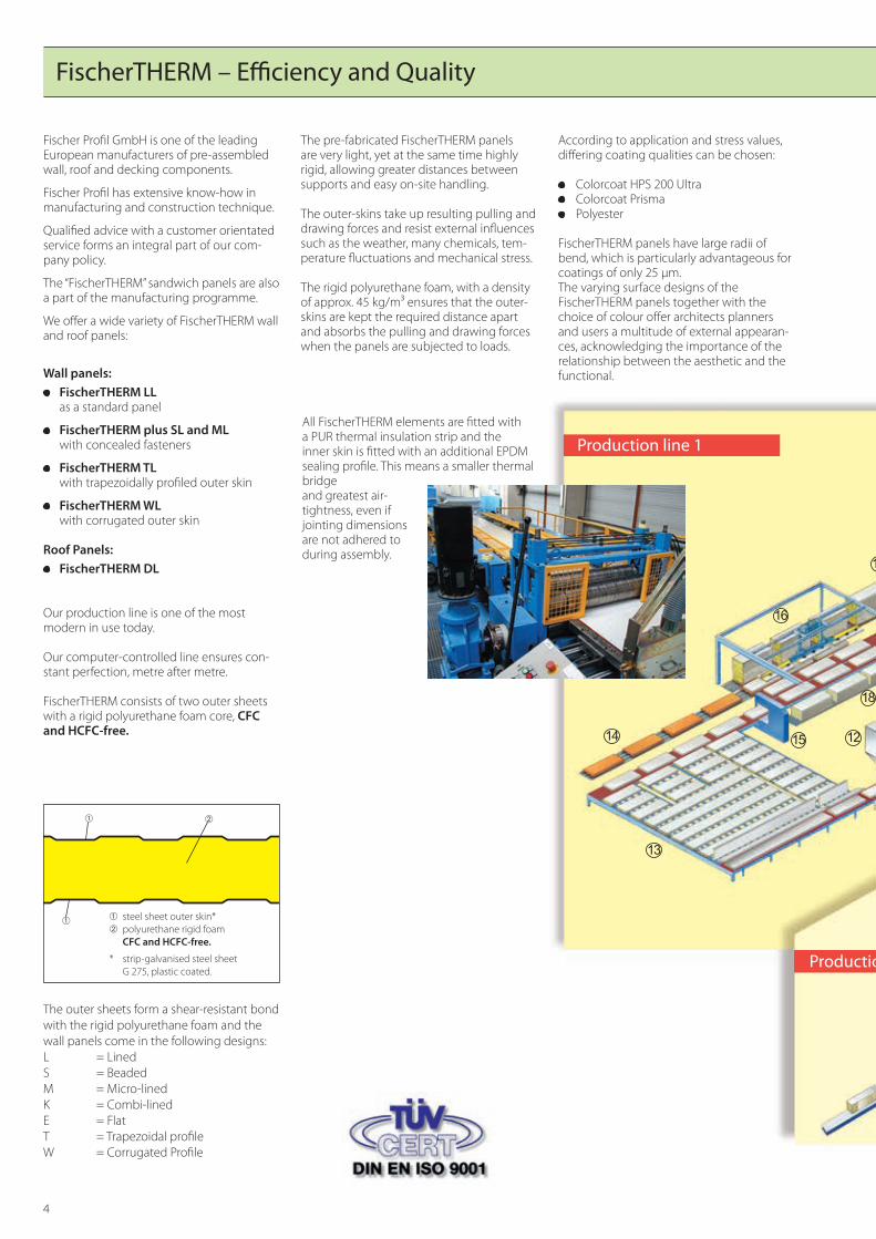
FischerTHERM – Efficiency and Quality
Fischer Profil GmbH is one of the leading European manufacturers of pre-assembled wall, roof and decking components.
Fischer Profil has extensive know-how in manufacturing and construction technique.
Qualified advice with a customer orientated service forms an integral part of our com-pany policy.
The “FischerTHERM” sandwich panels are also a part of the manufacturing programme.
We offer a wide variety of FischerTHERM wall and roof panels:
Wall panels: FischerTHERM LL
as a standard panel
FischerTHERM plus SL and ML with concealed fasteners
FischerTHERM TL with trapezoidally profiled outer skin
FischerTHERM WL with corrugated outer skin Roof Panels:
FischerTHERM DL
Our production line is one of the most modern in use today.
Our computer-controlled line ensures con-stant perfection, metre after metre.
FischerTHERM consists of two outer sheets with a rigid polyurethane foam core, CFC and HCFC-free.
The outer sheets form a shear-resistant bond with the rigid polyurethane foam and the wall panels come in the following designs:L = LinedS = BeadedM = Micro-linedK = Combi-linedE = FlatT = Trapezoidal profileW = Corrugated Profile
��
➀ steel sheet outer skin*➁ polyurethane rigid foam CFC and HCFC-free.
* strip-galvanised steel sheet G 275, plastic coated.
➀
➁➀
�
���
��
���
��
�
�
��
����
���
��
��
��
��
��
�
��
�
��
�
�
��
��
��
��
����
��
��
��
��
��
��
Production line 1
Production line 2
The pre-fabricated FischerTHERM panels are very light, yet at the same time highly rigid, allowing greater distances between supports and easy on-site handling.
The outer-skins take up resulting pulling and drawing forces and resist external influences such as the weather, many chemicals, tem-perature fluctuations and mechanical stress.
The rigid polyurethane foam, with a density of approx. 45 kg/m³ ensures that the outer-skins are kept the required distance apart and absorbs the pulling and drawing forces when the panels are subjected to loads.
According to application and stress values, differing coating qualities can be chosen:
Colorcoat HPS 200 Ultra Colorcoat Prisma Polyester
FischerTHERM panels have large radii of bend, which is particularly advantageous for coatings of only 25 µm.The varying surface designs of the FischerTHERM panels together with the choice of colour offer architects planners and users a multitude of external appearan-ces, acknowledging the importance of the relationship between the aesthetic and the functional.
All FischerTHERM elements are fitted with a PUR thermal insulation strip and the inner skin is fitted with an additional EPDM sealing profile. This means a smaller thermal bridge and greatest air-tightness, even if jointing dimensions are not adhered to during assembly.
5
�
���
��
���
��
�
�
��
����
���
��
��
��
��
��
�
��
�
��
�
�
��
��
��
��
����
��
��
��
��
��
��
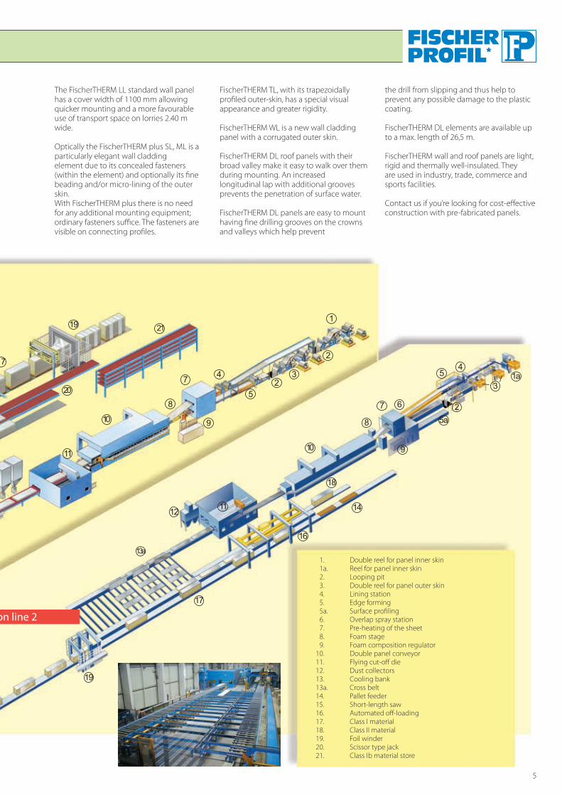
Production line 2
1. Double reel for panel inner skin 1a. Reel for panel inner skin 2. Looping pit 3. Double reel for panel outer skin 4. Lining station 5. Edge forming 5a. Surface profiling 6. Overlap spray station 7. Pre-heating of the sheet 8. Foam stage 9. Foam composition regulator10. Double panel conveyor11. Flying cut-off die12. Dust collectors13. Cooling bank13a. Cross belt14. Pallet feeder15. Short-length saw16. Automated off-loading17. Class I material18. Class II material19. Foil winder20. Scissor type jack21. Class Ib material store
The FischerTHERM LL standard wall panel has a cover width of 1100 mm allowing quicker mounting and a more favourable use of transport space on lorries 2.40 m wide.
Optically the FischerTHERM plus SL, ML is a particularly elegant wall cladding element due to its concealed fasteners (within the element) and optionally its fine beading and/or micro-lining of the outer skin.With FischerTHERM plus there is no need for any additional mounting equipment; ordinary fasteners suffice. The fasteners are visible on connecting profiles.
FischerTHERM TL, with its trapezoidally profiled outer-skin, has a special visual appearance and greater rigidity.
FischerTHERM WL is a new wall cladding panel with a corrugated outer skin.
FischerTHERM DL roof panels with their broad valley make it easy to walk over them during mounting. An increased longitudinal lap with additional grooves prevents the penetration of surface water.
FischerTHERM DL panels are easy to mount having fine drilling grooves on the crowns and valleys which help prevent
the drill from slipping and thus help to prevent any possible damage to the plastic coating.
FischerTHERM DL elements are available up to a max. length of 26,5 m.
FischerTHERM wall and roof panels are light, rigid and thermally well-insulated. They are used in industry, trade, commerce and sports facilities.
Contact us if you’re looking for cost-effective construction with pre-fabricated panels.

6
FischerTHERM – Product Range
A = inner skin B = outer skin
FischerTHERM1.)*
LL 40
LL 60
LL 80
LL 100
FischerTHERM plus
SL/ML 60
SL/ML 80
SL /ML 100
FischerTHERM **
TL 65
TL 85
Wall clading elementsFischerTHERM
WL 80
WL 100
Roof elementsFischerTHERM
DL 70
DL 80
DL 100
DL 120
DL 140
DL 160
1100
A
B
40-1
001000
A
B
60-1
00
1000
40 40/6
065
/85
84 116A
B
1000
58/7
878
/98
76,9A
B
1000
30-1
2070
-160
333,39040
A
B
On request, FischerTHERM roof elements are available with an additional sealing strip in the longitudinal joint.
1.) Other combinations of surface designs see brochure FischerTHERM page 7.
* From 1000 m² also available in 1000 mm construction width. Please enquire about coating/colour.** Trapezoidally profiled outer skin available in construction width of 800 mm.
Panel Typesheet thickness t [mm]
panel gauged [mm]
panel length max. L [m]
panel weightg [kg/m2]
heat transmis-sion coefficient U
[W/(m2K)]
heat transmis-sion resistance
R [m2 K/W]outerskinta [mm]
innerskinti [mm]
FischerTHERMLL40
0,55 0,50
40 121.) 10,4 0,58 1,56LL60 60 161.) 11,2 0,39 2,36LL 80 80 161.) 12,0 0,30 3,16LL100 100 161.) 12,8 0,24 3,96FischerTHERM plus
0,630,50
60 161.)
12,70,39 2,36SL 60/ML 60 0,632.) 13,8
0,752.) 14,8
0,630,50
80 161.)
13,50,30 3,16SL 80/ML 80 0,632.) 14,6
0,752.) 15,6
0,630,50
100 161.)
14,30,24 3,96SL 100/ML 100 0,632.) 15,4
0,752.) 16,4FischerTHERMTL 65
0,55 0,5065
161.)11,8 0,45 2,05
TL 85 85 12,4 0,33 2,85FischerTHERM
WL 80 0,630,50
78 161.)
13,30,36 2,600,632.) 14,4
0,752.) 15,5
WL 100 0,630,50
98 161.)
14,10,28 3,400,632.) 15,2
0,752.) 16,3FischerTHERMDL 70
0,55 0,45
70
261.)
10,5 0,69 1,28DL 80 80 10,9 0,54 1,68DL 100 100 11,7 0,38 2,48DL 120 120 12,5 0,29 3,28DL 140 140 13,4 0,23 4,08DL 160 160 14,0 0,20 4,88
1.) recommended max. length 2.) available on request
7
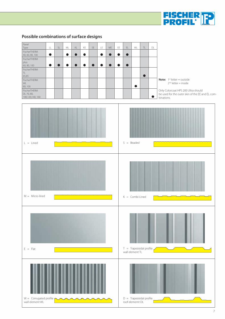
Possible combinations of surface designs
Panel Type LL SL ML KL KE SE LE ME EE EL WL TL DL
FischerTHERM 40, 60, 80, 100
FischerTHERM plus 60, 80, 100
FischerTHERM TL 65,85
FischerTHERM WL 80, 100
FischerTHERM DL 70, 80, 100,120,140, 160
Note: 1st letter = outside 2nd letter = inside
Only Colorcoat HPS 200 Ultra should be used for the outer skin of the EE and EL com-binations.
D = Trapezoidal profileroof elememt DL
W = Corrugated profilewall element WL
T = Trapezoidal profilewall element TL
E = Flat
M = Micro-lined
S = BeadedL = Lined
K = Combi-Lined

8
FischerTHERM – Coatings and colours
* The following standard colours are available in the 1000 mm construction width: Polyester, RAL 90024), 90063), 90103), Colorcoat HPS200, 10A05, 90024) and 55% AlZn AZ 185 (Aluzinc).FischerTHERM wall elements with 0.55 mm thick outer and inner skins can be manufactured from stainless steel (material no. 4301 III C). Please state the type of surface.
Ex-stock, short lead-time material Available on request
** FischerTHERM DL (outer skin 0,63 mm) also available in 55% AIZn AZ 185 (aluzinc).
1) Accent colours with surcharge2) PVFe coating with surcharge3) Only similar to RAL colour. There can be no guarantee that the colour will be uniform, even within a single delivery.4) Colour only similar to RAL
There is no need for any protective film with Colorcoat HPS 200 Ultra due to its high scratch-resistance.The outer-skin for FischerTHERM panels, with a 25 µmthick Polyester or Pvf2 coating, is always delivered complete with its environmentally friendly polyethelene film, which should be removed immediately after mounting.
Stress AnalysisThe rigid polyurethane foam core of the panels creates a shear-resistant bond which lessens the need for sheeting rails and purlins. The profiled wall panels TL and WL and the trapezoidal roof panels DL also help in this respect.
The FischerTHERM LL60 wall panels, when used as multi-span beams, require rail support approx. every 4.90 m, the FischerTHERM TL85 approx. every 6.14 m.
The FischerTHERM DL 80 roof element, used as a multi-span beam, requires purlins approx. every 4.00 m with a snow-load of 0.75 kN/m².
The above examples assume a light colour for the outer-skin and a max. deflection of ≤ L/150.
For more exact data on rail and purlin spacing, see the FischerTHERM load/span tables.
LicenceFischerTHERM roof and wall panels have been given the licence number Z-10.4-179 by the Berlin Institute for building components.
Beschichtungen /Farbton
Outside InsideFischerTHERM* 40, 60, 80, 100
TL 65, 85DL** 70, 80, 100, 120, 140, 160
FischerTHERM plus 60, 80, 100FischerTHERM
WL 80, 100
FischerTHERM FischerTHERM
40, 60, 80,100, plus, TL, WL
40, 60, 80,100 DL DL, WL, TL
Blechdicke [mm]0,55 0,63 0,50 0,55 0,45 0,55
Colorcoat HPS 200 Ultra, 200 µmWhite
Goosewing Grey
Terracotta
Hamlet
Merlin Grey
Heritage Green
Anthracite
Petra
Colorcoat Prisma, 50 µmRed Oxide RAL 3009
Anthracite RAL 7016
Grey White RAL 9002
Sirius ähnlich RAL 9006
Orion ähnlich RAL 9007
Polyester (SP), 25 µmLight Ivory RAL 1015Rubinrot 1)4) RAL 3003Gention blue 1) RAL 5010Sky blue 1) RAL 5015Moorland Green RAL 6005Reseda Green RAL 6011Chromium oxide green RAL 6020Anthracite 4) RAL 7016Light Grey 4) RAL 7035Dust Grey RAL 7037Copper RAL 8004Nut brown RAL 8011Reddish brown 1) RAL 8012Grey White 4) RAL 9002Grey White 2)4) RAL 9002White Aluminium 3) RAL 9006Grey Aluminium 3)RAL 9007Pure White 3) RAL 9010
Polyester (SP), 12 µmGrey White 3) RAL 9002
* Bei 1000 mm Baubreite sind folgende Standardfarbtöne vorhanden: Polyester, RAL 90024), 90063), 90103), Colorcoat HPS200, 10A05, 90024) und 55% AIZn AZ 185 (Aluzink)FischerTHERM Wandelemente mit 0,55 mm dicken Außen- und Innenschalen können auch aus Edelstahl (Werkstoff-Nr. 4301 III C) hergestellt werden. Bitte Oberflächenart angeben.

9
Special coatings
The planning of a building envelope starts with the selection
of a sustainable, state of the art coating system. The two new
coating systems, Colorcoat HPS 200 Ultra and Colorcoat Pris-
ma, combine corrosion resistance with the functionality and
aesthetics of a building envelope and provide excellent colour
fastness.
Colorcoat Prisma with a layer thickness of 50 µm has been de-
veloped to withstand environmental influences and is distin-
guished by its low weight, high durability and versatility. This
coating excels by virtue of its excellent colour and gloss fastness
and optimum corrosion resistance. The coil-coated Colorcoat
HPS 200 Ultra is highly resistant to scratching and abrasion.
Colorfarm is a cost-efficient coating system for the inside of
farm buildings. Due to its excellent corrosion resistance it is ide-
ally suited for aggressive, humid climatic conditions.
Your Confidex® guaranteeThe Confidex guarantee is available for all buildings and colours provided with Colorcoat HPS 200 Ultra and Prisma coating systems. The contractual guarantee is concluded by simply completing a registration form. Registration of your Confidex guarantee ensures that the performance of Color-coat HPS 200 Ultra (up to 40 years) and Prisma (up to 30 years) of the envelope of your building is guaranteed.
Example: Confidex guarantee Colorcoat HPS 200 Ultra
The term of protection is not a guaranteed period. It is a technical term which, with appropriate maintenance and care, can help the customer to determine a refurbishment programme. The guarantee period is in general shorter than the protection period and is agreed individually in negotiated contracts.
Examples of coating systems, corrosion categories and terms of protection (in accordance with DIN 55634)Coating system C1 C2 C3 C4 C5-I C5-M
Term of protection Low Middle High Low Middle High Low Middle High Low Middle High Low Middle High
Galvanized
Colorcoat® PE 15
Colorfarm®
Colorcoat HPS200 Ultra®
Colorcoat® PE 25
Colorcoat® PVDF
Colorfarm®
Colorcoat Prisma®
Colorcoat HPS200 Ultra®
Inside Outside
Signature Classical and matt Metallic colours colours colours

10
FischerTHERM – high insulation panels
Thermal InsulationThermal insulation is important for the following reasons:
it lessens heat loss through the walls and roof
it helps maintain the correct air balance for the building`s occupants
it protects the building itself against the damaging effects of damp
it lessens energy consumption for heating and cooling
it keeps production and management costs down.
In accordance with the energy saving decree (En EV 2002), since 1st February 2002 new, stiffer insulation requirements - particularly pertaining to walls and roofs - have had to be fulfilled including jointing, which must be permanently sealed airtight. Furthermore, the requirements of DIN 4108 (Insulation for Surface Engineering) must also be fulfilled.
Planners, architects and users must all consi-der the type or insulation to be used; a type which insulates well but is also cost effective.
Rigid polyurethane foam with its diffusion-proof outer-skins, fulfils these requirements and is the best insulating material on the market.
As regards potential fluctuations in the heat conductivity resulting from diffusion, our sheets may be considered as gas diffusion-proof, without special proof being given, provided they are made from metallic material of 50 µm gauge minimum. When the edge-area is less than 10 % of the total panel surface area, these edges do not need to be covered by the steel skin. Rigid polyurethane foam does not rot, remains decay and mould free, has no smell, and is physiologically safe with standard applications. The foam is also chemically neutral.
FischerTHERM with a PUR core and diffusion tight cover sheets achieves the lowest ther-mal conductivity of all insulation matreials, which leads to beneficial heat transfer coefficients U of less than 0.20 W/(m²/K) applicable to all types of elements.
The thermal retention capacity of Fischer-THERM panels is very small. When they are used for buildings which are not in constant use, these panels have obvious advantages over heavier materials, saving a considerable amount of energy.
You do not even have to think about humi-dity protection with FischerTHERM – there is simply no need. No moisture is allowed to seep in, or indeed out, of the panel thanks to the vapour-tight surfaces, ensuring long-life insulation.
The so-called “moisture balance” calculati-ons which are made for other construction materials are not necessary with Fischer-THERM.
Consideration of punctual thermal bridgesIn the area of metallic fasteners for Fischer-THERM sandwich elements, punctual heat losses occur which must be considered when determining the heat transfer coeffici-ent U according to the Energy Conservation Code.
At RWTH university, Aachen, the effect of thermal bridges due to metallic fasteners was determined by way of three-dimensio-nal numeric FEM calculations.
When FischerTHERM elements are fastened to a supporting structure consisting of trapezoidal profiles, thermal insulation of the polyurethane rigid foam is only slightly affected.
According to DIN EN ISO 6946, no correction must be made to consider screws as punc-tual thermal bridges if the overall correction is less than 3% of the U value.
For up to 3 stainless steel thread forming or drilling screws, the correction value is less than 3%; therefore undisturbed thermal insulation may be assumed when calcula-ting the heat transfer coefficient U0.
When using steel screws, the 3% limit is 1 screw per sq.m., as thermal conductivity of steel is 50 W/mk while that of stainless steel is 17 W/mk.
Quality AssuranceThe rigid polyurethane foam used in Fischer-THERM panels is subject to quality control and fulfils the requirements of DIN 18164 (Plastic Foam Acting as Insulating Material for Surface Engineering). FischerTHERM panels are synonymous with material of constant high quality.
Noise InsulationSound measurements at the testing room of the North-Rhine Westphalian National Material Testing Authority in Dortmund resulted in a noise insulation value of Rw = 25 dB for FischerTHERM LL 60 and Fischer-THERM plus sl 60, test certificate numbers 420520493-1 and 420520493-2.
In such composite panels the noise insula-tion value determined is approximately the same for all panel types and thicknesses.
Fire behaviourFire behaviour is divided into „Euroclasses“ A – F, according to DIN EN 13501 part 1. In particular flammability, flame spread and heat release are determining factors. Building materials of classes A2, B, C and D are also classified in terms of their smoke production by s1, s2 or s3, where smoke production increases from class s1 to s3. Flaming droplets according to classes A2, B, C and D are rated using classes d0, d1 or d2.
a) d0: No flaming droplets/particles
b) d1: Flaming droplets for a short time/particles
c) d2: Persistent flaming droplets /particles
FischerTHERM sandwich elements are space-enclosing, thermally insulating components for outer walls and roofs. Their fire behaviour has been rated in accordance with DIN EN 13501-1 as B-s3,d0, which is equivalent to the national official identifica-tion „hardly flammable“.
In addition, the outside of the FischerTHERM DL roof element is resistant to flying sparks and radiant heat in accordance with DIN 4102, part 7.
FischerTHERM DL elements therefore comply with the criteria placed on „hard roofing“ defined in the premium guidelines of the Verband der Sachversicherer (Associa-tion of Property Insurers). FischerTHERM roof and wall elements demonstrably display defensive behaviour in the event of a fire, i.e., they only burn in the area of direct heat impact from the fire source.
They assure building owners that a local fire will not spread across the roof or walls to another part of the building. Also, the foam will not produce flaming droplets.
FischerTHERM elements therefore do not contribute to maintenance or spread of a fire.
Lightning ProtectionAll Fischer construction elements with ≥ 0.5 mm thick outer steel sheets with metallic coatings can be used as natural components of a conducting device as per DINV ENV 61024-1 (lightning protection of constructional systems). The exterior may have a coating thickness of up to 500 µm.
The distance between the individual metal surfaces may not be greater than 1 mm, the overlap of the elements over each other must be at least 100 cm².
Metal walls can be used as conductors if the individual elements are joined together by bolts, rivets or by overlapping. A secure current-conducting connection to the eart-hing system and to the conducting device, e.g. through the connection between Fischer roof and wall panels, must be gua-ranteed. If Fischer construction elements,

11
The soft jointsealing strip with the additional EPDMsealing profile (DUO sealant) guarantee that FischerTHERM roof and wall cladding elements are extremely airtightand offer good thermal insulation.
e.g. FischerTHERM wall-cladding elements are not connected to each other in such a way that they will conduct electricity, but if the metal sub-structure is connected so that it conducts from the connection to the wall panels to the connection to the earthing system without interruption, then this can be used as a conductor.
Sealed JointingIf correct mounting procedures are observed with regard to the male-female jointing, FischerTHERM roof and wall panels will remain watertight and airtight. The tightness of the jointing seals (a-value) is just as significant in construction elements as the U-value, for example.
The energy-saving decree (EnEV 2002) requires among other things the minimising of thermal bridges and a greater air tightness of the joints of thermally conducting surrounding surfaces. Particularly with increasing thermal insulation standards, heat loss through ventilation makes, relatively seen, a significant difference and can even exceed the transmission heat loss - denoted by the U-value - considerably.
If sandwich elements are to be employed, you should pay particular attention to the a-value. The soft joint-sealing strip with the additional EPDM sealing profile (DUO sealant) guarantee that FischerTHERM roof and wall cladding elements are extremely airtight and offer good thermal insulation.
Such space-enclosing construction elements generally require a minimum value of
a ≤ 0.10 m³/h ⋅ m(daPa)2/3.
The roof element was impervious to rainwater up to a rainwater volume of 3 litres/min. . m² and at a wind speed of up to 12 m / second.
One particular advantage of the registered utility model male/female jointing of FischerTHERM elements is that the nominal width of the joint need no longer necessarily be adhered to. Even in the case of the assembly being not quite exact, a very high degree of joint sealing is nevertheless provided.
In order to prove this, we had further tests performed at the Technical University of Cot-tbus in April 2002. A 40 mm thick Fischer-THERM wall element with a nominal joint width of 8 mm was tested, and, for purposes of comparison, an 11 mm panel, i.e. with a 3 mm wider longitudinal joint compared with the nominal joint width.
The a-value in the case of the 11 mm joint width on a simulation of a badly assembled wall was still 0.02 m³/(h . m . (da Pa) 2/3.
Compared with the state of the art value of a ≤ 0.1 m³/h . m . (da Pa) 2/3, this means that this value is five times as good.
Be sure to choose FischerTHERM elements with the new DUO sealant.
When using sandwich elements for cold stores with high air humidity, e.g. potato stores, it is recommended that the longitudinal joint and all connections are provided with an additional sealing on the outside, in order to take account of the vapour pressure difference. For roof elements, a sealing tape should be inserted into the outer longitudinal joint overlap. For wall elements, an injectable sealant should be applied to the outer groove area before joining the tongues and grooves.
When sandwich panels are rigidly fastened, the outer sheet is subject to elongation which induces tension and deformation of the sandwich element as a result of the temperature impacts. This may lead to the production of noises in the supporting structure, in particular when it is made from timber.
Quality ControlManufacturing is subject to independent and internal monitoring required by the building supervision licence.
The internal examinations during manufac-turing and independent examinations by a state material testing authority guarantee that the material, galvanization, sheet thickness, foam properties and dimensional accuracy of the quality assured composite panels fulfil the set quality requirements. The so-called conformity procedure (ÜZ) is required for composite panels. That means the conformity of the product’s properties with the relevant technical specifications, and the presence of effective internal production checking must be proven and monitored by a recognised examining and monitoring authority for building supervision. Once the certifying authority has issued a certificate of conformity, we are entitled to use the “Ü” symbol. The manufacturer, the basis of the certificate of conformity, the licence number and the certifying authority can be read from the “Ü” symbol on the cards supplied with the bundles.
Fischer ProfilGmbH
Z-10.4-179
12
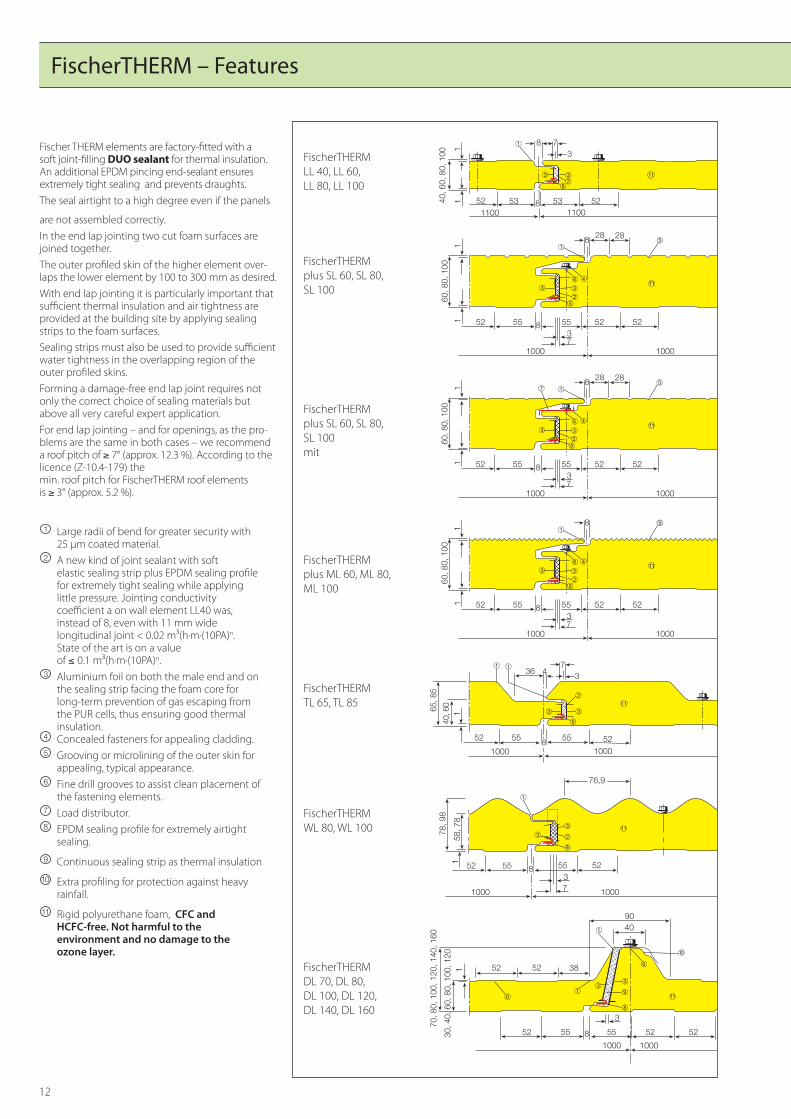
FischerTHERM LL 40, LL 60, LL 80, LL 100
FischerTHERM plus ML 60, ML 80,ML 100
FischerTHERM DL 70, DL 80, DL 100, DL 120, DL 140, DL 160
FischerTHERM WL 80, WL 100
FischerTHERM TL 65, TL 85
FischerTHERM plus SL 60, SL 80,SL 100
FischerTHERM plus SL 60, SL 80, SL 100mit
Fischer THERM elements are factory-fitted with a soft joint-filling DUO sealant for thermal insulation. An additional EPDM pincing end-sealant ensures extremely tight sealing and prevents draughts.The seal airtight to a high degree even if the panels
are not assembled correctiy.In the end lap jointing two cut foam surfaces are joined together.The outer profiled skin of the higher element over-laps the lower element by 100 to 300 mm as desired. With end lap jointing it is particularly important that sufficient thermal insulation and air tightness are provided at the building site by applying sealing strips to the foam surfaces.Sealing strips must also be used to provide sufficient water tightness in the overlapping region of the outer profiled skins.Forming a damage-free end lap joint requires not only the correct choice of sealing materials but above all very careful expert application. For end lap jointing – and for openings, as the pro-blems are the same in both cases – we recommend a roof pitch of ≥ 7° (approx. 12.3 %). According to the licence (Z-10.4-179) the min. roof pitch for FischerTHERM roof elementsis ≥ 3° (approx. 5.2 %).
� Large radii of bend for greater security with 25 µm coated material.� A new kind of joint sealant with soft
elastic sealing strip plus EPDM sealing profile for extremely tight sealing while applying little pressure. Jointing conductivity coefficient a on wall element LL40 was, instead of 8, even with 11 mm wide longitudinal joint < 0.02 m³(h·m·(10PA)n. State of the art is on a value of ≤ 0.1 m³(h·m·(10PA)n.� Aluminium foil on both the male end and on
the sealing strip facing the foam core for long-term prevention of gas escaping from the PUR cells, thus ensuring good thermal insulation.� Concealed fasteners for appealing cladding.� Grooving or microlining of the outer skin for
appealing, typical appearance.� Fine drill grooves to assist clean placement of
the fastening elements.� Load distributor.� EPDM sealing profile for extremely airtight
sealing.
� Continuous sealing strip as thermal insulation
�� Extra profiling for protection against heavy rainfall.
�� Rigid polyurethane foam, CFC and HCFC-free. Not harmful to the environment and no damage to the ozone layer.
FischerTHERM – Features
70, 8
0, 1
00, 1
20, 1
40, 1
60
30, 4
0, 6
0, 8
0, 1
00, 1
20
��
���������� ����
� �������
����
����
��
�� �
� ��
��
�
�
��
���
��
�
�
��
��� ��
�����
����
��
��
� �� ������
���� ����
�
�
��
���
��
�
�
��
�
��� ��
�����
����
��
��
� �� ������
���� ����
�
�
��
���
��
�
�
��
�
�����
����
��
��
� �� ������
���� ����
�
�
�
�
�
�
�
��� ��
� ��������
���� ����
�����
������
�
�
��
�
78, 9
8
58, 7
8

13
�
�
�
Steel Frame1 Steel sheeting-rail2 FischerTHERM 3 6.3 x L Diameter stainless steel self- sealing screw with a 16 mm dia. washer
Fastening Your FischerTHERM Wall Panels
Longitudinal Lap Jointing1 Steel purlin2 FischerTHERM DL3 JT3-2H-5,5 x 25 – E 19/2 self-drilling screw Max. separation 500 mm
Timber Frame2 FischerTHERM DL7 Timber purlin8 6.5 x L Diameter stainless steel selfsealing screw with a 22 mm dia. washer, to be fixed through the crown
Reinforced Concrete Frame2 FischerTHERM DL3 6.3 x L Diameter stainless steel selfsealing screw with a 22 mm dia. washer4 Concrete purlin5 Flat steel bar running the legth of the concrete6 Hard foam filler
Steel Frame1 Steel purlin2 FischerTHERM DL3 6.3 x L Diameter stainless steel self- sealing screw with a 22 mm dia. washer
Fastening Your FischerTHERM DL Roof Panels
Timber Frame2 FischerTHERM7 Timber beam8 6.5 x L Diameter stainless steel selfsealing screw with a 16 mm dia. washer
Reinforced Concrete Frame2 FischerTHERM3 6.3 x L Diameter stainless steel selfsealing screw with a 16 mm dia. washer4 Concrete sheeting-rail5 Flat steel bar running the legth of the concrete6 Hard foam filler

14
FischerTHERM – Panel Fixing Requirements
Examples of element fastening for FischerTHERM
The examples show possible fastener arrangements but they do not replace a structural analysis of the connections.
FischerTHERM DL 70, 80, 100, 120, 140, 160, 3 Self-sealing screws per purlin with a 22 mm dia. washer
FischerTHERM DL 70, 80, 100, 120, 140, 160, 2 Self-sealing screws per purlin with a 22 mm dia. washer
FischerTHERM DL roof panels must be secured to the frame-structure according to individual stress requirements.FischerTHERM DL panels cannot be used to strengthen the frame-structure.
Minimum Roof Pitch for FischerTHERM DL Roof Panels
For roofs without end lap jointing ≥ 5° (8,8 %) For roofs with end lap jointing or roof apertures ≥ 7° (12,3 %)
We recommend an additional sealing strip in the longitudinal joint: For roofs without end lap jointing ≤ 7° For roofs with end lap jointing or roof apertures ≤ 10°
The examples show possible fastener arrangements but they do not replace a structural analysis of the connections.
FischerTHERM LL 40, 60, 80, 100, 2 Self-sealing screws per rail, near the male-female jointing
FischerTHERM wall panels must be secured to the frame-structure according to individual stress requirements.
FischerTHERM plus SL 60, 80, 100/ML 60 ,80,100 (with load distributors), 1 Self-sealing screw per rail or 2 sealing screws40 mm below eacht other
FischerTHERM TL 65, 85, 2 Self-sealing screws per rail
FischerTHERM WL 80, 100, 3 Self-sealing screws per rail
FischerTHERM plus SL 60, 80, 100/ML 60, 80, 100 (with load distributors), 2 Self-sealing screws per rail 40 mm below each other
FischerTHERM LL 40, 60, 80, 100, 3 Self-sealing screws per rail
FischerTHERM TL 65, 85, 4 self-sealing screws per rail
FischerTHERM WL 80, 100, 4 self-sealing screws per rail

15
FischerTHERM DL elements can be supplied with a foam-free area between 100 mm and 300 mm at the end of the panel in order to produce a clean end lap on the roof or leave eaves free from both physical and optical obstructions.
Internal bonding of the rigid polyurethane foam and the steel sheet is prevented through the application of a special separa-ting agent.
The foam-free area can be manufactured in widths of between 100mm and 300 mm in steps of 50 mm.
Please note the 2 different types of panels which come with the foam-free area:R = RightL = Left
If the trapezoidal lap profile can be seen
from the left side, looling from the eaves outward, then panel (L) should be ordered, if not, then panel (R) is needed.
FischerTHERM DL with foam-free area
FischerTHERM – End Lap
� �
���������������������������������������������� ��������
����������������������������������
���������������������������������������������� ���������
����������������������������������������� ���������� �������������������������
�����������������������������������������������������������������������������������������������������
� ���������� � ���������
����
�������������
���������
� ����������
� �������������
�������������
���������
��������������������������������������������������������������������������������������������������������������� ����������������������������������������������������
� ����������������������������������������������
�����������������
���
���
200 standard
200 standardPermanently elastic sealing strip as protection against rain, self-adhesive on one side illac 20 x 2 mm
illac 20 x 4 mm
We recommend a roof pitch of min. 7°

16
Dauerelastisches Dichtbandals Regendichtung,einseitigselbstklebend,illac 20 x 2 mm
FischerTHERM – Fasteners
Fasteners
FischerTHERM LL FischerTHERM plus FischerTHERM TL FischerTHERM 40 60 80 100 60 80 100 65 85 WL 80 WL 100
JZ3- JZ3- JZ3- JZ3- JZ3- JZ3- JZ3- JZ3- JZ3- JZ3- JZ3- 6,3x64 6,3x80 6,3x100 6,3x115 6,3x64 6,3x80 6,3x100 6,3x64 6,3x80 6,3x80 6,3x100 -E 16 -E 16 -E 16 -E 16 -E 19* -E 19* -E 16* -E 16 -E 16 -E 14/3 -E 14/3 (Valley) (Valley) (Valley) (Valley) JA3- JA3- JA3- JA3- JA3- JA3- JA3- JA3- JA3- JA3- JA3- 6,5x115 6,5x125 6,5x150 6,5x175 6,5x115 6,5x125 6,5x150 6,5x115 6,5x125 6,5x125 6,5x150 -E 16 -E 16 -E 16 -E 16 -E 19* -E 19* -E 16* -E 16 -E 16 -E 14/3 -E 14/3 (Valley) (Valley) (Valley) (Valley)
JA3- JA3- JA3- JA3- JA3- JA3- JA3- 6,5 x 45 6,5 x 45 6,5 x 45 6,5 x 45 6,5 x 45 6,5 x 64 6,5 x 64 -E 16 -E 16 -E 16 -E 16 -E 16 -E 16 -E 16
Steel and reinforced concrete≥ 2 mm
Timber
Joint and cover profile region
Flashings JT3-3H-5,5 x 25-E16 self-drilling screw or AI/E 4,8 x 8,3 blind rivet (clamping range 0,8-3,2 mm), max. sep. 500 mm (shell Al, drift stainless steel)
Non-rusting steel screws
Wall panels
Structure
Steel and reinforced concrete≥ 2 mm
Timber
Longitudinal jointing
Flashings JT3-3H-5,5 x 25-E16 self-drilling screw or AI/E 4,8 x 8,3 blind rivet (clamping range 0,8-3,2 mm), max. sep. 500 mm (shell Al, drift stainless steel)
Roof panels
Structure FischerTHERM DL 70 80 100 120 140 160
JZ3-6,3 x 64 JZ3-6,3 x 64 JZ3-6,3 x 80 JZ3-6,3 x 100 JZ3-6,3 x 115 JZ3-6,3 x 135 -E 22 -E 22 -E 22 -E 22 -E 22 -E 22 (Valley) (Valley) (Valley) (Valley) (Valley) (Valley) JZ3-6,3 x 90 JZ3-6,3 x 100 JZ3-6,3 x 125 JZ3-6,3 x 150 JZ3-6,3 x 175 JZ3-6,3 x 200 -E 22 -E 22 -E 22 -E 22 -E 22 -E 22 (crown) (crown) (crown) (crown) (crown) (crown)
JA3-6,5 x 150 JA3-6,5 x 150 JA3-6,5 x 175 JA3-6,5 x 200 JA3-6,5 x 230 JA3-6,5 x 230 -E 22 -E 22 -E 22 -E 22 -E 22 -E 22 fix fix fix fix fix fix through the through the through the through the through the through the crown only crown only crown only crown only crown only crown only JT3-2H- JT3-2H- JT3-2H- JT3-2H- JT3-2H- JT3-2H- 5,5 x 25 5,5 x 25 5,5 x 25 5,5 x 25 5,5 x 25 5,5 x 25 -E 19/2 -E 19/2 -E 19/2 -E 19/2 -E 19/2 -E 19/2 (Max. sep. (Max. sep. (Max. sep. (Max. sep. (Max. sep. (Max. sep. 500 mm) 500 mm) 500 mm) 500 mm) 500 mm) 500 mm)
Non-rusting steel screws
Fasteners
* If load distributors are also used for fastening, an E16 washer must also be used.Only those fasteners meeting IFBS Z 14.4 – 407 approval may be used.See brochure “Flashings and Accessories”
Only those fasteners meeting IFBS Z 14.4 – 407 approval may be used.See brochure “Flashings and Accessories”

17
FischerTHERMPermissible drawing values zul. F (kN) of fasteners depending on the sheet thickness of the outer skin.
FischerTHERM plus, with load distributorsPermissible drawing values zul. F (kN) of fasteners depending on the number of screws.Sheet thickness of outer skin ≥ 0,55 mm
��
�
��� ��
�����
����
��
��
� �� ������
���� ����
�
Support Fastening Permissible values zul F [kN]
Intermediate 1 screw 5,33 support 2 screws 5,62
End 1 screw 1,87 support 2 screws 2,39
Screws: EJOT JZ3-6,3 x L - E16Distance between 2 screws ≥ 40 mm.Distance of screws from edge of panel in end support ≥ 80 mm. Load distributors made from 1.5 mm steel sheet.Alloy galvanizing AZ 185 (DIN EN 10215), ßS = 320 N/mm²
The values stated in the table are to be seen exclusively as permissible drawing forces with regard to composite panels.The transfer of the drawing forces to the substructure must be calculated separately.
�
�
����
���
�� ���� ��
�����
����
����
����
���
Sheet thickness – outer skin
Element type ta = 0,55 mm ta = 0,63 mm
➀ ➁ ➀ ➁LL 40 0,90 0,70 – – LL 60 0,90 0,70 – – LL 80 0,90 0,70 – – LL 100 0,90 0,70 – – TL 65/85 0,90 0,70 1,40 0,90 WL 80/100 – – 1,40 0,90DL 70 0,90 0,70 1,40 0,90 DL 80 0,90 0,70 1,40 0,90 DL 100 0,90 0,70 1,40 0,90 DL 120 0,90 0,70 1,40 0,90DL 140 0,90 0,70 1,40 0,90 DL 160 0,90 0,70 1,40 0,90
➀ Steel structure t ≥ 2,00 mm, screw type: EJOT JZ3 - 6,3 x L-E16
➀ Timber structure, screw type: EJOT JA3 - 6,5 x L-E16
FischerTHERM plus, without load distributorsPermissible drawing values zul. F (kN) of fasteners depending on the number of screws.Sheet thickness of outer skin ≥ 0,55 mm
��
�
��� ��
�����
����
��
��
� �� ������
���� ����
�Screws: EJOT JZ3-6,3 x L - E19Distance between 2 screws ≥ 40 mm.Distance of screws from edge of panel in end support – with 1 screw ≥ 70 mm – with 2 screws ≥ 50 mm
Support Fastening Permissible values zul F [kN]
Intermediate 1 screw 1,73
support 2 screws 2,18
End 1 screw 0,97
support 2 screws 1,05
The values stated in the table are to be seen exclusively as permissible drawing forces with regard to composite panels.The transfer of the drawing forces to the substructure must be calculated separately.
➀ ➁
18
FischerTHERM – Details
� �
�
�
��� ��
��
��
�
��
�
�
�
��
�
�
�
�
��
��
���
��
��
��
����
��
�
��
�
�� ��
��
����
��
��
������
��
��
�
�
�
�
��
����
����
��
��
��
�
�
����
��
��
����
�
��
���
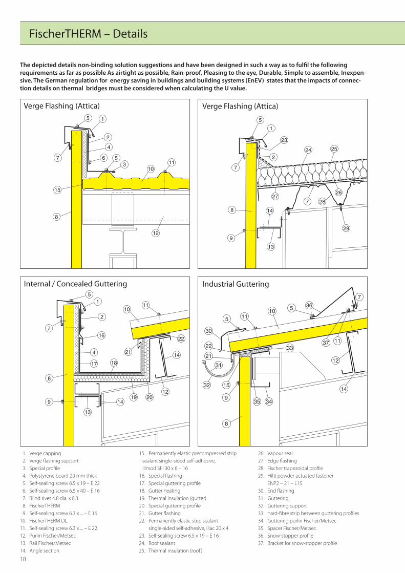
1. Verge capping 2. Verge flashing support 3. Special profile 4. Polystyrene board 20 mm thick 5. Self-sealing screw 6.5 x 19 – E 22 6. Self-sealing screw 6.5 x 40 – E 16 7. Blind rivet 4.8 dia. x 8.3 8. FischerTHERM 9. Self-sealing screw 6.3 x ... – E 1610. FischerTHERM DL11. Self-sealing screw 6.3 x ... – E 2212. Purlin Fischer/Metsec13. Rail Fischer/Metsec14. Angle section
15. Permanently elastic precompressed strip sealant single-sided self-adhesive, illmod SFI 30 x 6 – 16
16. Special flashing17. Special guttering profile18. Gutter heating19. Thermal insulation (gutter)20. Special guttering profile21. Gutter flashing22. Permanently elastic strip sealant single-sided self-adhesive, illac 20 x 423. Self-sealing screw 6.5 x 19 – E 1624. Roof sealant25. Thermal insulation (roof )
Verge Flashing (Attica) Verge Flashing (Attica)
Internal / Concealed Guttering Industrial Guttering
26. Vapour seal27. Edge flashing28. Fischer trapezoidal profile29. Hilti powder actuated fastener ENP2 – 21 – L1530. End flashing31. Guttering32. Guttering support33. hard-fibre strip between guttering profiles34. Guttering purlin Fischer/Metsec35. Spacer Fischer/Metsec36. Snow-stopper profile37. Bracket for snow-stopper profile
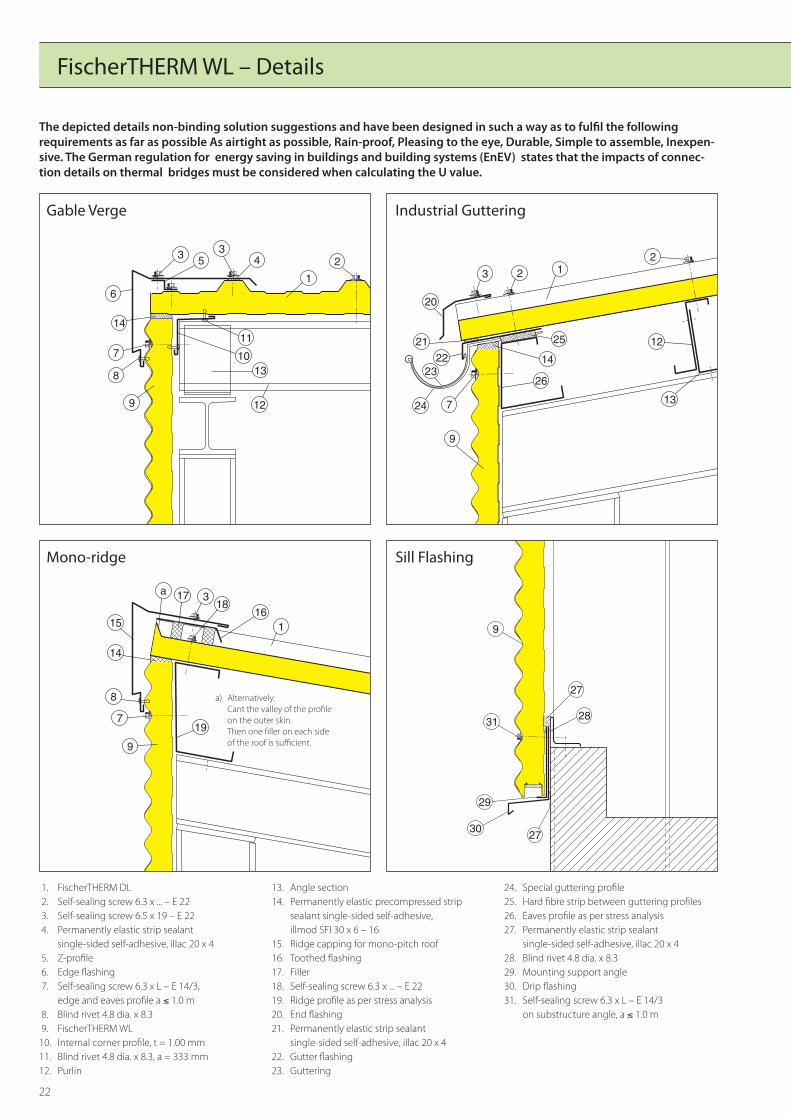
The depicted details non-binding solution suggestions and have been designed in such a way as to fulfil the following requirements as far as possible As airtight as possible, Rain-proof, Pleasing to the eye, Durable, Simple to assemble, Inexpen-sive. The German regulation for energy saving in buildings and building systems (EnEV) states that the impacts of connec-tion details on thermal bridges must be considered when calculating the U value.

19
��
����
�� ���� ��
���
��
� � � ��
��
�
�
�
�
����
�� ��
�
����
�
���
����
�
�
�
�
�
��
��
����������� ����������������� �������������������������� ����� ������ ����������������������� ������� ������
��
��
��
��
�
���
����� �
��������������� ���������������� ����� ������ ���������������������������������� ���������������� ��������
������
�
Gable Verge Mono-ridge
RidgeValley Guttering
1. Edge flashing 2. Self-sealing screw 6.5 x 19 – E 22 3. Z-profile 4. Blind rivet 4.8 dia. x 8.3 5. FischerTHERM 6. Self-sealing screw 6.3 x ... – E 16 7. Permanently elastic precompressed strip sealant single-sided self-adhesive, illmod SFI 30 x 6 – 16 8. Permanently elastic strip sealant single-sided self-adhesive, illac 20 x 4 9. FischerTHERM DL10. Self-sealing screw 6.3 x ... – E 22
11. Purlin12. Rail13. Angle section14. Angle section15. Gutter flashing16. Special guttering profile17. Gutter heating18. Thermal insulation (gutter)19. Special guttering profile20. Permanently elastic strip sealant single-sided self-adhesive, illac 20 x 421. Ridge capping for mono-pitch roof22. Toothed flashing
23. Profile filler strips24. Ridge profile25. Ridge profile interior26. Filler PUR-M (moisten element edges)27. Tie bolt28. Self-sealing screw 6.3 x ... – E 22
The depicted details non-binding solution suggestions and have been designed in such a way as to fulfil the following requirements as far as possible As airtight as possible, Rain-proof, Pleasing to the eye, Durable, Simple to assemble, Inexpen-sive. The German regulation for energy saving in buildings and building systems (EnEV) states that the impacts of connec-tion details on thermal bridges must be considered when calculating the U value.
a) Alternatively:Cant the valley of the profile on the outer skin. Then one filler on each side of the roof is sufficient.
a) Alternatively:Cant the valley of the profile on the outer skin. Then one filler on each side of the roof is sufficient.
20
FischerTHERM – Details
�
��
�
��
�
��
�� �
��
�
�
�
�
�
�
�
�
�
� � �� �
�
��
��
���
�
�
��
�
�
�
� �
�
�
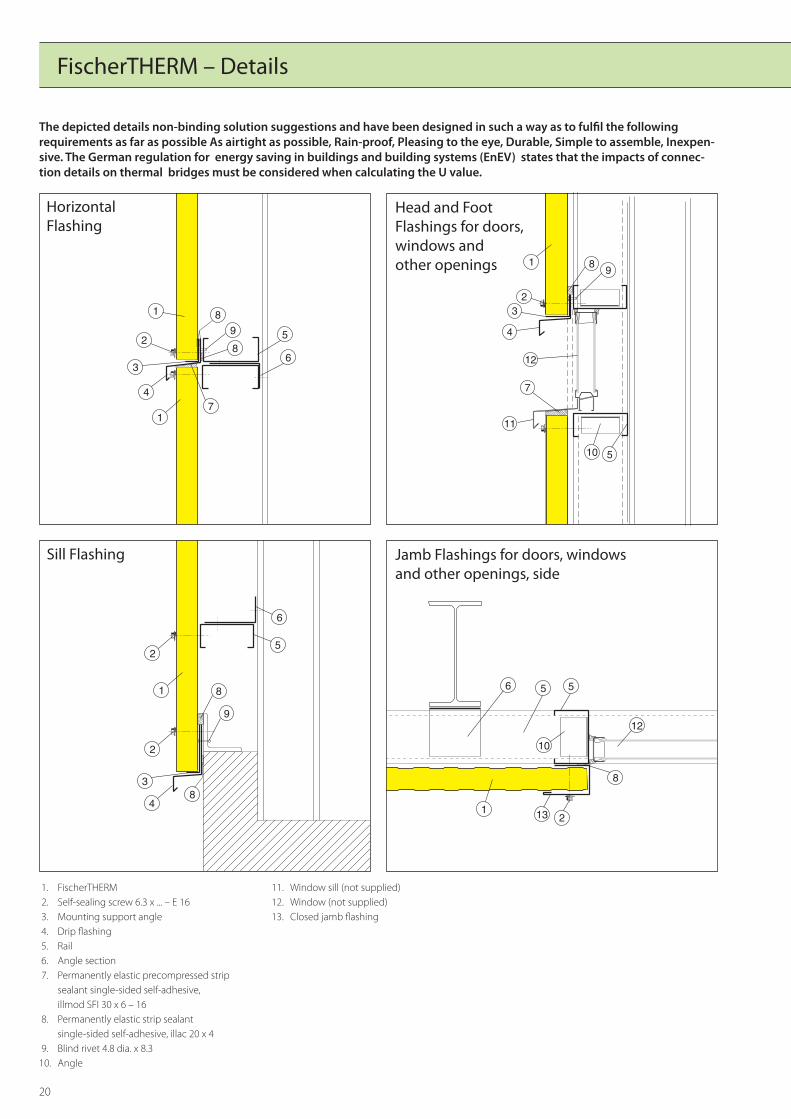
Horizontal Flashing
Head and FootFlashings for doors,windows andother openings
Sill Flashing Jamb Flashings for doors, windowsand other openings, side
1. FischerTHERM 2. Self-sealing screw 6.3 x ... – E 16 3. Mounting support angle 4. Drip flashing 5. Rail 6. Angle section 7. Permanently elastic precompressed strip sealant single-sided self-adhesive, illmod SFI 30 x 6 – 16 8. Permanently elastic strip sealant single-sided self-adhesive, illac 20 x 4 9. Blind rivet 4.8 dia. x 8.310. Angle
11. Window sill (not supplied)12. Window (not supplied)13. Closed jamb flashing
The depicted details non-binding solution suggestions and have been designed in such a way as to fulfil the following requirements as far as possible As airtight as possible, Rain-proof, Pleasing to the eye, Durable, Simple to assemble, Inexpen-sive. The German regulation for energy saving in buildings and building systems (EnEV) states that the impacts of connec-tion details on thermal bridges must be considered when calculating the U value.

21
�
�
�
�
��
�
�
�
�
��
�
�
�
�
�
�
�
��
��
��
��
�
��
��
��
������
��
��
��
���� ��
�� ��
��
��
������
��
��
��
External and Internal Corners External and Internal Corners
Skylight Connectors,transversally to the roof element
1. FischerTHERM 2. Self-sealing screw 6.3 x ... – E 16 3. External corner flashing 4. Blind rivet 4.8 dia. x 8.3 5. Internal corner flashing 6. Rail 7. Angle section 8. Permanently elastic precompressed strip sealant single-sided self-adhesive, illmod SFI 30 x 6 – 16 9. Flat metal strip, welding on building site10. FischerTHERM DL11. Connecting profile, special flashing
12. Z-profile13. Skylight frame, self-supporting, not supplied14. Thermal insulation15. Skylight16. Purlin17. Angle section18. Self-sealing screw 6.3 x ... – E 2219. Self-sealing screw 6.5 x 19 – E 2220. Permanently elastic strip sealant single-sided self-adhesive, illac 20 x 421. Self-sealing screw 6.3 x ... – E 2222. Connecting profile, special flashing
Skylight Connectors,lengthways to the roof element
23. Toothed flashing24. Skylight frame, self-supporting, not supplied25. Filler PUR-M (moisten element edges)26. Filler
The depicted details non-binding solution suggestions and have been designed in such a way as to fulfil the following requirements as far as possible As airtight as possible, Rain-proof, Pleasing to the eye, Durable, Simple to assemble, Inexpen-sive. The German regulation for energy saving in buildings and building systems (EnEV) states that the impacts of connec-tion details on thermal bridges must be considered when calculating the U value.
22
� � ��
�
�
��
����
���
�
�
��
�
� � ��
��
��
��
��
����
��
�
�� �
��
��
���
���
��
��
��
�
�
�
��
�
������������ ��������������������������������������������������������������������������������������������������
�
��
��
�� ��
��
��
Gable Verge Industrial Guttering
Mono-ridge Sill Flashing
1. FischerTHERM DL 2. Self-sealing screw 6.3 x ... – E 22 3. Self-sealing screw 6.5 x 19 – E 22 4. Permanently elastic strip sealant single-sided self-adhesive, illac 20 x 4 5. Z-profile 6. Edge flashing 7. Self-sealing screw 6.3 x L – E 14/3, edge and eaves profile a ≤ 1.0 m 8. Blind rivet 4.8 dia. x 8.3 9. FischerTHERM WL 10. Internal corner profile, t = 1.00 mm11. Blind rivet 4.8 dia. x 8.3, a = 333 mm12. Purlin
13. Angle section14. Permanently elastic precompressed strip sealant single-sided self-adhesive, illmod SFI 30 x 6 – 1615. Ridge capping for mono-pitch roof16. Toothed flashing17. Filler18. Self-sealing screw 6.3 x ... – E 2219. Ridge profile as per stress analysis20. End flashing21. Permanently elastic strip sealant single-sided self-adhesive, illac 20 x 422. Gutter flashing 23. Guttering
FischerTHERM WL – Details
24. Special guttering profile25. Hard fibre strip between guttering profiles26. Eaves profile as per stress analysis27. Permanently elastic strip sealant single-sided self-adhesive, illac 20 x 428. Blind rivet 4.8 dia. x 8.329. Mounting support angle30. Drip flashing31. Self-sealing screw 6.3 x L – E 14/3 on substructure angle, a ≤ 1.0 m
The depicted details non-binding solution suggestions and have been designed in such a way as to fulfil the following requirements as far as possible As airtight as possible, Rain-proof, Pleasing to the eye, Durable, Simple to assemble, Inexpen-sive. The German regulation for energy saving in buildings and building systems (EnEV) states that the impacts of connec-tion details on thermal bridges must be considered when calculating the U value.
a) Alternatively: Cant the valley of the profile on the outer skin. Then one filler on each side of the roof is sufficient.

23
��
�
��
��
��
�
�
�
��
��
�
�
�
��
�
��
��
� � ��
���
��
��
��
��
��
�
�
�
�
�
�
��
�
Exterior Corner Head and FootFlashings for doors,windows andother openings
Exterior Corner Head and Foot Flashings for doors, windows and other openings, side
1. FischerTHERM WL 2. Exterior corner profile 3. Self-sealing screw 6.3 x L – E 14/3, a ≤ 1 m 4. Blind rivet 4.8 dia. x 8.3 in every fifth crown of corrugation 5. Permanently elastic precompressed strip sealant single-sided self-adhesive, illmod SFI 30 x 6 – 16 6. Permanently elastic sealant illseal NO only on the longitudinal lap of the element 7. Angle as support 8. Flat metal strip as support 9. Blind rivet 4.8 dia. x 8.3, a ≤ 0.5 m
10. Mounting support angle11. Drip flashing12. Permanently elastic strip sealant single-sided self-adhesive, illac 20 x 413. Permanently elastic precompressed strip sealant single-sided self-adhesive, illmod SFI 30 x 6 – 1614. Window sill (not supplied)15. Window (not supplied)16. Closed jamb flashing17. Side corner connection flashing18. Rail19. Angle
The depicted details non-binding solution suggestions and have been designed in such a way as to fulfil the following requirements as far as possible As airtight as possible, Rain-proof, Pleasing to the eye, Durable, Simple to assemble, Inexpen-sive. The German regulation for energy saving in buildings and building systems (EnEV) states that the impacts of connec-tion details on thermal bridges must be considered when calculating the U value.

24
FischerTHERM – Horizontal laying
1 FischerTHERM plus 2 aluminium pilaster strip type 2 3 aluminium decking profile type 1 4 support profile 1.5 mm thick (Aluzinc) type 1 5 self-sealing screw 6.5 x 45 - E 16, a ≤ 1.0 m 6 self-sealing screw 6.3 x 45 - E 19 7 self-sealing screw 6.3 x L - E 16, a ≤ 1.0 m 8 2K sealing 9 permanently elastic sealing strip, single-sided self-adhesive, illac 20 x 2 10 self-sealing screw 6.3 x 80-E 19 11 aluminium pilaster strip type 1 12 aluminium decking profile type 2 13 FischerTHERM WL 14 self-sealing screw 6.3 x 80-E14/3 15 support profile 1.5 mm thick (Aluzinc) type 2 16 blind rivet AI/E 4.8 x 8.3 a ≤ 1.0 m 17 flat steel bar with rigid foam filling 18 self-sealing screw 6.3 x 100-E14/3 19 aluminium pilaster strip 3.00 mm thick 20 self-sealing screw 6.5 x 64 - E 16, a ≤ 1.0 m21 support profile 1.5 m thick (Aluzinc) type 222 self-sealing screw 6.3 x 100 - E 19
�����
�
� �
� �
���� ��
�������
Jointing, SL60/ML60 plus
� �
���
���� ��
���
�����
�
�
�� ���
Jointing, SL80/ML80 plus
����� ��������
�� �
��
� ��
���
��
������ ����
��
����
Jointing, WL80
Jointing, WL100
Jointing, SL100/ML100 plus
The German regulation for energy saving in buildings and building systems (EnEV) states that the impacts of connection details on thermal bridges must be considered when calculating the U value.

25
DeliveryUpon delivery the load must be checked for missing items as well as goods which have been damaged in transit. Fischer must be advised of problems straight away.
Off LoadingThe pallets should be off-loaded on site with a suitable fork-lift, using strapping, not cables.Special tie-bars should be used with packs over 10 m long. Pallets under 6 m may be off-loaded with a stacker truck.Place edge protecting angles on top of the bundles or wooden spacers between the belts or ropes (Fig. 1).
Care must be taken not to bend the bundles too much and they should be stacked in the order they will be needed.Do not stack more than two wooden pallets on top of each other (Fig. 2)
StorageThe bundles should not be stored on the ware-house floor, but rather on storage blocks rising at one end (Fig. 3).
The bundles should be protected against direct sunlight, water and dirt, preferably with a tarpaulin.Condensation can be avoided with sufficient aeration, leaving the cover open a little on top but ensuring that the wind cannot blow it off (Fig. 4).
Water must not be allowed to collect between the panels, since this can cause corrosion.
Protective FilmThe protective film put on the panels at the factory should be removed immediately after mounting and certainly no later than four weeks thereafter.
Cutting to SizePanels should be cut to size with a suitable compass saw or circular hand saw. The sawing blade should have extra-fine teeth and should cut the material cold, so that the panel surface is not damaged (Fig. 5).
Touch UpsMinor damage to Colorcoat HPS 200 Ultra or polyester coatings resulting from installation should be repaired using a fine hair brush and air-drying repair lacquer on as small an area as possible. For wall elements, flaws should only be repaired if they extend down to the base material as the touch-up lacquer will stand out from the coil coating over time as a result of ageing. Touch-up lacquer may be purchased from Fischer Profil.
Air-tightnessDuring installation, it should be ensured that all connections such as roof/wall, wall/wall or con-nections at openings or rows of windows are sealed so that they are permanently air tight according to the state of the art. Depending on the application, compressible, open-cell polyu-rethane tape, PVC tape, plastic or elastic sealant or aluminium tape laminated with butyl rubber may be used. For larger apertures, suitable PUR foam may also be used. For proper fastening of sandwich elements, the fasteners should be tightened until the seal underneath the screw head is lightly deformed. This brings about a slight bulging of the top cover sheet of the sandwich element. Such light deformations in the top cover sheet of sandwich elements which arise from the method of fastening are not defects.The next FischerTHERM plus element is pushed with its tongue across the sealing screw into the groove of the element which has already been installed, so that a joint gap of approx. 8 mm is achieved on the outside. Any drilling chips should be immediately removed from
horizontal surfaces so as to avoid the formation of rust. A correctly installed wall must form a straight line at the lower edge of the elements.
Mounting your Fischer FischerTHERM Wall PanelsDuring mounting, local accident prevention regulations and the “Guidelines for the Assem-bly of Profiled Panels for Roof, Wall and Decking Construction” by the IFBS must be observed.First of all, check the frame-structure for surface flatness and ensure that perpendicular ele-ments are indeed perpendicular.Order inconsistencies are to be reported to Fischer and suppementary orders to be placed, or modifications to be made,iif necessary.FischerTHERM wall panels are normally mounted vertically, but they can also be placed horizontally.Before mounting, the panel`s cover width is to be marked on the frame-structure, and single-sided self-adhesive sealing-strips should be stuck to the frame-structure, as per the laying plan.FischerTHERM panels should be handled with great care, so as not to damage the plastic coating. The panels must be carried up-end avoiding bending and the female part of the male-female jointing is not to be used as a hand-grip (Fig. 6).
The wall panels are raised behind the frame with a crane and then positioned.Manual assembly is also common, where the panels are manhandled onto the frame and then brought vertical with ropes(Fig. 7).
If the wall panels are to be laid horizontally, then both ends should be secured with screw clamps. The outer-skin must also be protected against such clamps with smooth spacers.
1
2
3
5
4
6
7
FischerTHERM – Assembly Instructions
26
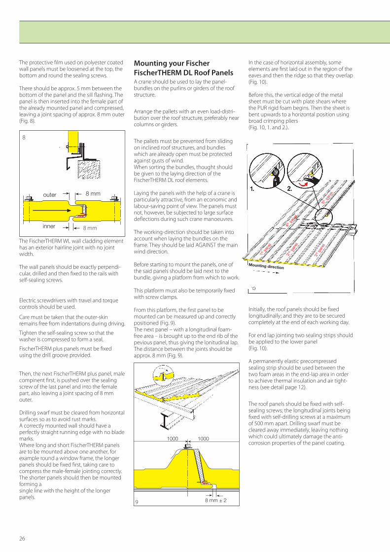
The protective film used on polyester coated wall panels must be loosened at the top, the bottom and round the sealing screws.
There should be approx. 5 mm between the bottom of the panel and the sill flashing. The panel is then inserted into the female part of the already mounted panel and compressed, leaving a joint spacing of approx. 8 mm outer (Fig. 8).
The FischerTHERM WL wall cladding element has an exterior hairline joint with no joint width.
The wall panels should be exactly perpendi-cular, drilled and then fixed to the rails with self-sealing screws.
Electric screwdrivers with travel and torque controls should be used.
Care must be taken that the outer-skin remains free from indentations during driving.
Tighten the self-sealing screw so that the washer is compressed to form a seal.
FischerTHERM plus panels must be fixed using the drill groove provided.
Then, the next FischerTHERM plus panel, male compinent first, is pushed over the sealing screw of the last panel and into the female part, also leaving a joint spacing of 8 mm outer.
Drilling swarf must be cleared from horizontal surfaces so as to avoid rust marks.A correctly mounted wall should have a perfectly straight running edge with no blade marks.Where long and short FischerTHERM panels are to be mounted above one another, for example round a window frame, the longer panels should be fixed first, taking care to compress the male-female jointing correctly. The shorter panels should then be mounted forming a single line with the height of the longer panels.
In the case of horizontal assembly, some elements are first laid out in the region of the eaves and then the ridge so that they overlap (Fig. 10).
Before this, the vertical edge of the metal sheet must be cut with plate shears where the PUR rigid foam begins. Then the sheet is bent upwards to a horizontal position using broad crimping pliers(Fig. 10, 1. and 2.).
Initially, the roof panels should be fixed longitudinally; and they are to be secured completely at the end of each working day.
For end lap jointing two sealing strips should be applied to the lower panel(Fig. 10).
A permanently elastic precompressed sealing strip should be used between the two foam areas in the end-lap area in order to achieve thermal insulation and air tight-ness (see detail page 12).
The roof panels should be fixed with self-sealing screws; the longitudinal joints being fixed with self-drilling screws at a maximum of 500 mm apart. Drilling swarf must be cleared away immediately, leaving nothing which could ultimately damage the anti-corrosion properties of the panel coating.
Mounting your Fischer FischerTHERM DL Roof PanelsA crane should be used to lay the panel-bundles on the purlins or girders of the roof structure.
Arrange the pallets with an even load-distri-bution over the roof structure, preferably near columns or girders.
The pallets must be prevented from sliding on inclined roof structures, and bundles which are already open must be protected against gusts of wind.When sorting the bundles, thought should be given to the laying direction of the FischerTHERM DL roof elements.
Laying the panels with the help of a crane is particularly attractive, from an economic and labour-saving point of view. The panels must not, however, be subjected to large surface deflections during such crane manoeuvres.
The working-direction should be taken into account when laying the bundles on the frame. They should be laid AGAINST the main wind direction.
Before starting to mount the panels, one of the said panels should be laid next to the bundle, giving a platform from which to work.
This platform must also be temporarily fixed with screw clamps.
From this platform, the first panel to be mounted can be measured up and correctly positioned (Fig. 9).The next panel – with a longitudinal foam-free area – is brought up to the end rib of the pevious panel, thus giving the lonitudinal lap.The distance between the joints should be approx. 8 mm (Fig. 9).
���� ����
��������9
�������������������
������������������
����
����
�����
����� 8 mm
8

27
References
����
��
��
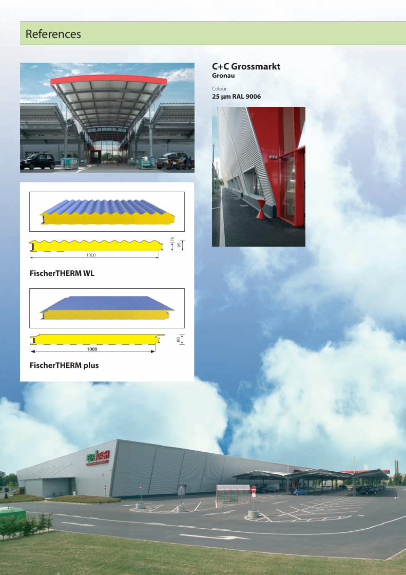
FischerTHERM WL
����
�
FischerTHERM DL
Protec GmbHHaslach
Colour: 25 µm RAL 9006
���
����
28
C+C GrossmarktGronau
Colour: 25 µm RAL 9006
����
��
��
FischerTHERM plus
FischerTHERM WL
��
1000
References

29
SporthalleBurg Stargat
Colour: 25 µm RAL 1015, 9002, 9010
FischerTHERM plus
��
1000

30
FischerTHERM plus
AREXXZwolle (NL)
Colour: 25 µm RAL 7016
��
1000
References
31
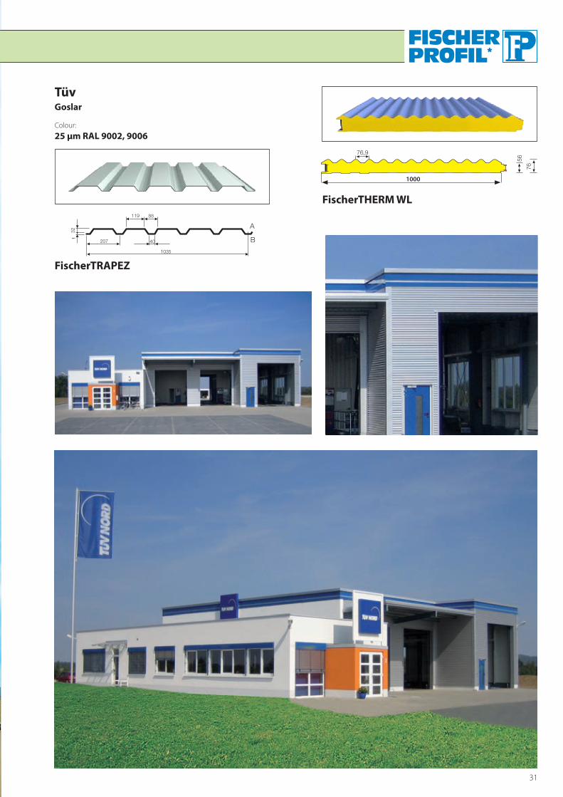
FischerTHERM WL
��
��
����
1000
Tüv Goslar
Colour: 25 µm RAL 9002, 9006
��� ��
��
����
���
���
�
�
FischerTRAPEZ

32
FischerTHERM plusdach
����
�
NahversorgungszentrumLangenselbold
Colour: 25 µm RAL 8012
���
����
References

33
����
��
��
FischerTHERM plus
FischerTHERM WL
OHB-System AGBremen
Colour: PulverColour RAL 702125 µm RAL 9010
��
1000

34
References
FischerTHERM plus
FischerTHERM WL
Gewerbebau NordRotenburg/Wümme
Colour: 25 µm RAL 900725 µm RAL 300025 µm RAL 9006
��
��
��
����
1000

36
Product range
FischerTHERM
FischerTRAPEZ
FischerTRAPEZ-Acoustic
FischerKASSETTE
FischerKASSETTE-Acoustic
FischerWELLE
FischerPANEEL
FischerKLIPTEC
Flashings and accessories
Fischer Profi l GmbH · Waldstraße 67 · D-57250 Netphen-Deuz · Telefon +49 (0)27 37/5 08-3 19 · Telefax +49 (0)27 37/ 5 08-3 13E-Mail: info@fi scherprofi l.de · http://www.fi scherprofi l.com
Die
se In
form
atio
nen
sind
nac
h b
este
m W
isse
n un
d G
ewis
sen
erst
ellt
wor
den.
Tat
a S
teel
– e
insc
hlie
ßlic
h ih
rer
Toch
terg
esel
lsch
afte
n –
über
nim
mt j
edoc
h ke
ine
Haf
tung
für
Info
rmat
ione
n, d
ie s
ich
eve
ntue
ll al
s ir
refü
hren
d h
erau
sste
llen
könn
ten.
Rep
rodu
ktio
n un
d N
achd
ruck
ver
bote
n.
.
����������
�����������
����������
�����������
1220
10 D
ata
subj
ect t
o ch
ange
with
out n
otic
e06
.201
2 D
ata
subj
ect t
o ch
ange
with
out n
otic
e
This
info
rmat
ion
has b
een
crea
ted
in th
e kn
owle
dge
and
belie
f tha
t it i
s acc
urat
e. Ta
ta st
eel a
nd it
s sub
sidia
ries d
oes n
ot a
ccep
t res
pons
ibili
ty o
r lia
bilit
y fo
r erro
rs o
r inf
orm
atio
n w
hich
is fo
und
to b
e m
islea
ding
. Re
prod
uctio
n is
proh
ibite
d.