FIRST EXPERIENCES WITH THE LHC BLM SANITY CHECKS
7
FIRST EXPERIENCES WITH THE LHC BLM SANITY CHECKS B. Dehning a , E. Effinger a , J. Emery a , A. Nordt a , M.G. Sapinski a , C. Zamantzas a a CERN, CH-1211 Genève 23, Switzerland E-mail: [email protected] ABSTRACT: The reliability concerns have driven the design of the LHC BLM system from the early stage of the studies up to the present commissioning and the latest development of diagnostic tools. To protect the system against non-conformities, new ways of automatic checking have been developed and implemented. These checks are regularly and systematically executed by the LHC operation team to insure that the system status is after each test "as good as new". The sanity checks are part of this strategy. They are testing the electrical part of the detectors (ionisation chamber or secondary emission detector), their cable connections to the front-end electronics, further connections to the back-end electronics and their ability to request a beam abort. During the installation and in the early commissioning phase, these checks have shown their ability to find also non-conformities caused by unexpected failure event scenarios. In every day operation, a non-conformity discovered by this check inhibits any further injections into the LHC until the check is run successfully again. KEYWORDS: Instrumentation for particle accelerators and storage rings - high energy (linear accelerators, synchrotrons).
Transcript of FIRST EXPERIENCES WITH THE LHC BLM SANITY CHECKS

FIRST EXPERIENCES WITH THE LHC BLM SANITY CHECKS
B. Dehninga, E. Effingera, J. Emerya, A. Nordta, M.G. Sapinskia, C. Zamantzasa
a CERN, CH-1211 Genève 23, Switzerland E-mail: [email protected]
ABSTRACT: The reliability concerns have driven the design of the LHC BLM system from the early stage of the studies up to the present commissioning and the latest development of diagnostic tools. To protect the system against non-conformities, new ways of automatic checking have been developed and implemented. These checks are regularly and systematically executed by the LHC operation team to insure that the system status is after each test "as good as new". The sanity checks are part of this strategy. They are testing the electrical part of the detectors (ionisation chamber or secondary emission detector), their cable connections to the front-end electronics, further connections to the back-end electronics and their ability to request a beam abort. During the installation and in the early commissioning phase, these checks have shown their ability to find also non-conformities caused by unexpected failure event scenarios. In every day operation, a non-conformity discovered by this check inhibits any further injections into the LHC until the check is run successfully again.
KEYWORDS: Instrumentation for particle accelerators and storage rings - high energy (linear accelerators, synchrotrons).

– 1 –
Contents
1. LHC BLM Overview 1 1.1 Hardware 1 1.2 Reliability 2
2. Sanity checks 2 2.1 Internal and external beam permit check 2 2.2 Connectivity check 3 2.3 Optimization of the connectivity check 3 2.4 Reproducibility of measurements 4
3. Non-conformities 4
1. LHC BLM Overview
The Beam Loss Monitoring (BLM) system for the Large Hadron Collider (LHC) has been designed to protect the machine equipments against unexpected energy deposition by losses especially on the superconducting magnets. When a partial loss of the proton beam around the ring exceeds a predetermined threshold, the system sends a beam abort request, which will result in a complete dump of both beams. In addition to the protective functionality, the system is used as measurement instrument for various studies and fine tuning of the accelerator.
1.1 Hardware
There are about 4000 monitors around the 27km of the LHC ring concentrated in the straight sections and on arc quadrupole magnets. The wildly used detector is an ionisation chamber, which has a high voltage supply and electrically represents a current source with high dynamic range (10e9).
The signal of 8 of these detectors is integrated and digitalized every 40µs by the Current to Frequency card (BLECF) [1] with a dynamic range of about 10e8 (10pA to 1mA). The resulting data are transmitted to the surface through a redundant optical link to the Threshold Comparators card (BLETC) [2]. This card produces longer integration windows up to 80s and continuously compares these values to predefined thresholds. Additionally, this card processes the maximum of these running sums every second for display and long term logging. In the case of losses above the thresholds, the card inhibits the beam permit signal, which is sent to the Combiner and Survey card (BLECS) and transmitted further to other systems to abort the beam. This last card also takes care of various checks sequences including the sanity checks.
The figure 1.1 gives a complete hardware overview from the ionisation chambers (left) to the VME crates and all externally connected systems (right). Higher level software blocks are shown in blue (top) and in blue also the system providing or receiving safety critical signals (bottom).

– 2 –
Figure 1.1: Overview of the LHC BLM hardware system
1.2 Reliability
The reliability concerns have driven the design and implementation of the LHC BLM system. The PhD thesis of G.Guaglio [3] has introduced the calculation of the failure rate of the main components. Based on this first results, failure scenarios have been identified and strategies to minimize them have been developed. The component reception procedures, installation and yearly maintenance, regular checks and continuous checks are the areas where various actions have been taken.
The focus of this paper is on the regular checks of the hardware combined under the name sanity checks. The idea is to reduce as much as possible the probability of a failure event leading to an incident by detecting non conformities on the system before problematic situations will occur. To achieve this goal, the system should be checked as often as possible without reducing significantly the availability (the system is unavailible when being checked). The regular check of the settings, called online check [4], which ensures the consistency between settings held inside the front-end and in the LHC Software Architecture (LSA) database will not be covered. To enforce the triggering of these procedures, hardware timers are implemented. If not triggered at least every 24h, the next injection in the LHC will be blocked through the beam permit lines connecting to the Beam Interlock System (BIS).
2. Sanity checks
As previously introduced, the sanity checks are the procedures, which are regularly running to ensure that the hardware is in a defined state, i.e. “as good as new”. In case of a detected non-conformity, the beam permit is not given back and no injections in the LHC can be performed. The internal beam permit check and the connectivity check [5] are different parts of this procedure.
2.1 Internal and external beam permit check
The internal beam permit check ensures that all Thresholds Comparators cards are able to fire the beam dump and that a signal is correctly passed through the daisy chaining of VME crates. To perform this check, the processing has been introduced in the Field-Programmable Gate Array FPGA of the Combiner card. All the Threshold Comparators are firing the beam dump one after each other and the FPGA checks that these signals are propagated to all the VME crates interconnected. The external beam permit check tests the connection between the BLM

– 3 –
system and the machine interlock interface (CIBUS) and is under the responsibility of the Beam Interlock System (BIS).
Figure 2.1: The internal beam permit check tests the beam permit links (red arrows), the external beam permit check tests connection from the BLM to the interlock system (blue arrow).
2.2 Connectivity check
The primary purpose of this check is to ensure the integrity of the cabling of each beam loss monitor. By adding a small harmonic modulation signal (0.06Hz, 30V) on the high voltage supply of the monitors (1500V), it is possible to detect a small current on the measurement side. If anywhere in the signal chain a cable is missing, disconnected or discontinued for any reason, the measurement will not show any harmonic variation of the current.
The second goal is to survey the integrity of the components. The measured amplitude and phase of every channel (monitor or spare) is compared to a predefined threshold measured for every channel. If one of them is outside the limits, the test will fail and the beam permit will not be raised.
This procedure takes place in the BLECS (Combiner) card FPGA. For this purpose the standard data are written by the VME crate CPU onto the memory of the FPGA. In the FPGA digital filtering is applied, as well as amplitude and phase recognition and finally threshold comparisons against the predefined reference database (LSA) settings.
The entire period of each channel are also saved into the volatile memory of the card. A dedicated application has been developed to download, save and analyze the information and display channel signals. It also generates warnings when signals are getting close to the accepted limit. In addition it is possible to display individual or groups of channels for analysis.
2.3 Optimization of the connectivity check
Since the first implementation and the tests of the connectivity check functionality, an optimisation has been applied to meet the requirements and minimize the influence on the system itself.
The harmonic amplitude excitation has been doubled to increase the signal to noise ratio on the secondary emission monitors (10 times smaller than the IC). To avoid a too long lasting negative induced current on the IC (the lower part of the sinus is now truncated) the frequency of the modulation has been doubled. Systematic measurements have shown very good reproducibility even with a truncated signal. The signal to noise ratio of the SEM has thus being improved, which results in a better reproducibility as well.
The second part of the improvement concerns the digital processing. The parameters of the low pass filter were optimized to improve the smoothing of the “stairs effect” and the rejection of unwanted parasitical frequencies (see Fig.2.3). The offset subtraction to the calculated amplitude has been introduced as well. Since the signal is not any more a harmonic signal (for IC) it helps to get rid of the influence of this offset to the calculated amplitude.

– 4 –
Figure 2.3: Volatile memory data for IC (left) and SEM (right). The raw data received from the CPU (stairs) are smoothed by a low pass filter (FIR) before amplitude and phase determination.
2.4 Reproducibility of measurements
To compute the reproducibility of the connectivity check, which includes the latest changes of the hardware, multiple executions were performed in a row (100 in total). Root and python scripts are used to extract the measured data from the databases. Figure 2.4 shows the results for the IC (top) and the SEM (bottom) by a two dimensional representation. The standard deviation of the 100 checks is plotted versus amplitude (left) and phase (right). As expected, the amplitude repeatability of the IC is better than for the SEM since the signal is about 10 times higher. The difference in amplitude can be explained by the differences in the equivalent circuit capacitance, 312pF for the IC and 22pF for the SEM.
Figure 2.4: Connectivity check measurements for the IC (top) and SEM (Bottom).
3. Non-conformities
During the commissioning of the LHC BLM installation in 2009 and during the early stage of the operation, multiple types of non-conformities have been detected by the connectivity check. The table 1 highlights the occurrences of these events and the resulting signal deviation from the expected behaviour. Comparing these values with the repeatability measured before, we can see that they can easily be detected by the system.
– 5 –
Table 1: Overview of the non-conformities detected with the connectivity check Type of non‐conformities Occurrence
s Parameter modified Deviation from the
expected behavior Parameters sensitivity (IC)
Chamber filter badly soldered or disconnected
27 phase and amplitude 9%‐33% 3% and 2%
Tunnel card (BLECF) non‐conform behavior on one or more channel
4 phase 10%‐30% 3%
Monitor not supplied with high voltage
4 Phase and amplitude Large 3% and 2%
Connection of monitor on the wrong channel
3 Phase and amplitude Large 3% and 2%
High voltage distribution box 1 Phase and amplitude Large 3% and 2%
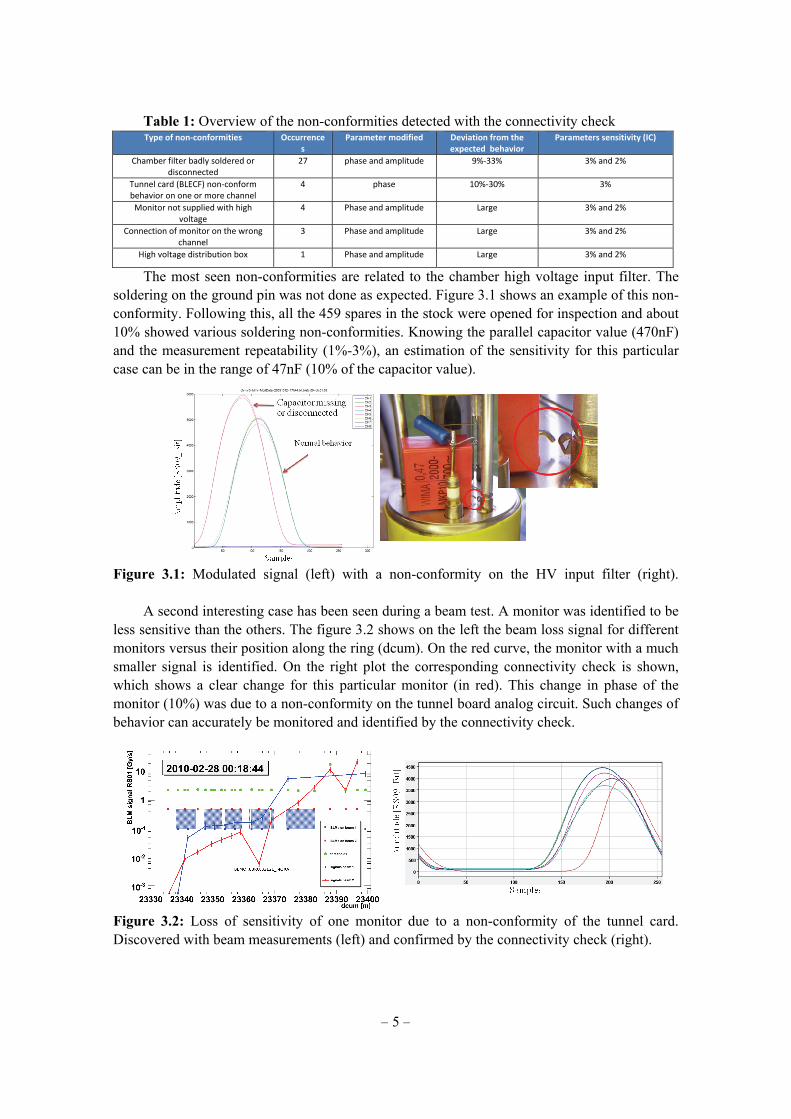
The most seen non-conformities are related to the chamber high voltage input filter. The soldering on the ground pin was not done as expected. Figure 3.1 shows an example of this non-conformity. Following this, all the 459 spares in the stock were opened for inspection and about 10% showed various soldering non-conformities. Knowing the parallel capacitor value (470nF) and the measurement repeatability (1%-3%), an estimation of the sensitivity for this particular case can be in the range of 47nF (10% of the capacitor value).
Figure 3.1: Modulated signal (left) with a non-conformity on the HV input filter (right).
A second interesting case has been seen during a beam test. A monitor was identified to be less sensitive than the others. The figure 3.2 shows on the left the beam loss signal for different monitors versus their position along the ring (dcum). On the red curve, the monitor with a much smaller signal is identified. On the right plot the corresponding connectivity check is shown, which shows a clear change for this particular monitor (in red). This change in phase of the monitor (10%) was due to a non-conformity on the tunnel board analog circuit. Such changes of behavior can accurately be monitored and identified by the connectivity check.
Figure 3.2: Loss of sensitivity of one monitor due to a non-conformity of the tunnel card. Discovered with beam measurements (left) and confirmed by the connectivity check (right).

– 6 –
4. Summary
The sanity checks are parts of the global strategy of high reliability of the LHC BLM system. They are checking regularly the hardware and searching for non-conformities on the monitor cabling and its internal parts. The link to the beam interlock system to inhibit the next injection in case of non-conformity and the integration of their executions into the LHC sequencer has been completed during the shutdown 2009-2010. It ensures the regularity of their executions for the luminosity increase toward the nominal operation of the LHC. After few months of operating them on a daily basis, the stability of the procedures and the reproducibility of the measurements have been confirmed. The accuracy of the connectivity check results obtained by the optimization of the procedure parameters and the signal processing have enabled the detection of unexpected variation of components values. It extended the use of this check to the detection of non-conformity on the high voltage filter of individual ionization chambers as well as specific decrease of the sensitivity of the current to frequency card. In addition to these unexpected features, the detection of disconnected monitors has been confirmed by real case in the LHC tunnel. The fast execution time of about 6 minutes has also allowed these checks to become a convenient way of regularly checking the conformity of the cabling as well as multiple part of the hardware of the LHC BLM system.
References
[1] E. Effinger, B. Dehning, J. Emery, G. Ferioli, G.Gauglio, C. Zamantzas, "The LHC Beam Loss Monitoring System's Data Acquisition Card", 12th Workshop on Electronics for LHC and future Experiments (LECC 06), Valencia, Spain. http://cdsweb.cern.ch/record/1027422/files/p108.pdf
[2] C. Zamantzas, B. Dehning, E. Effinger, J. Emery, G.Ferioli, "An FPGA Based Implementation for Real-Time Processing of the LHC Beam Loss Monitoring System's Data", Nuclear Science Symposium Conference Record, 2006. IEEE, vol.2, no., pp.950-954, Oct. 29 2006-Nov. 1 2006. http://ieeexplore.ieee.org/xpl/freeabs_all.jsp?arnumber=4179157
[3] G. Guaglio, “Reliability of the Beam Loss Monitor System for the Large Hadron Collider at CERN” , PhD. Thesis, University Clermont-Ferrand II – Blaise Pascal, Clermont-Ferrand, France
[4] C. Zamantzas, B. Dehning, J. Emery, J. Fitzek, F. Follin, S. Jackson, V. Kain, G. Kruk, M. Misiowiec, C. Roderick, M. Sapinski ,CERN, Geneva, Switzerland, "Configuration and validation of the LHC beam loss monitoring system", 9th European Workshop on Beam Diagnostics and Instrumentation for Particle Accelerators (DIPAC 09), Basel, Switzerland, http://dipac09.web.psi.ch/Proceedings/papers/tupb31.pdf
[5] J. Emery, B. Dehning, E. Effinger, G. Ferioli, C. Zamantzas, CERN, Geneva, Switzerland; H. Ikeda, KEK, Ibaraki, Japan; E. Verhagen, IceCube, UW-Madison, USA, "LHC BLM single channel connectivity test using the standard installation", 9th European Workshop on Beam Diagnostics and Instrumentation for Particle Accelerators (DIPAC 09), Basel, Switzerland, http://dipac09.web.psi.ch/Proceedings/papers/tupd26.pdf