FireCR Flash Manual
35
User Manual Computed Radiography Reader Doc No. : TM-401-EN Rev 1.2.2 Apr 2015 Part No. : CR-FPM-44-001-EN 3DISC, FireCR, Quantor and the 3D Cube are trademarks of 3D Imaging & Simulations Corp, South Korea, and its affiliates. All other trademarks are held by their respective owners and are used in an editorial fashion with no intention of infringement. The data in this publication are for illustration purposes only and do not necessarily represent standards or specifications, which must be met by 3D Imaging & Simulations Corp. All information contained herein is intended for guidance purposes only, and characteristics of the products and services described in this publication can be changed at any time without notice. Products and services may not be available in your local area. Please contact your local sales representative for availability information. 3D Imaging & Simulations Corp. strives to provide as accurate information as possible, but shall not be responsible for any typographical error. © Copyright 2014 3D Imaging & Simulations Corp. All rights reserved.
-
Upload
dlc-australia-pty-ltd -
Category
Documents
-
view
243 -
download
0
description
Â
Transcript of FireCR Flash Manual
User Manual Computed Radiography Reader
Doc No. : TM-401-EN Rev 1.2.2 Apr 2015
Part No. : CR-FPM-44-001-EN
3DISC, FireCR, Quantor and the 3D Cube are trademarks of 3D Imaging & Simulations Corp,
South Korea, and its affiliates. All other trademarks are held by their respective owners and
are used in an editorial fashion with no intention of infringement. The data in this publication
are for illustration purposes only and do not necessarily represent standards or specifications,
which must be met by 3D Imaging & Simulations Corp. All information contained herein is
intended for guidance purposes only, and characteristics of the products and services described
in this publication can be changed at any time without notice. Products and services may not
be available in your local area. Please contact your local sales representative for availability
information. 3D Imaging & Simulations Corp. strives to provide as accurate information as
possible, but shall not be responsible for any typographical error.
© Copyright 2014 3D Imaging & Simulations Corp. All rights reserved.

User Manual
FireCR Flash TM-401-EN
2
Contact
3D Imaging & Simulations Corp. Bldg.1, 48, Yuseong-daero 1184 beon-gil, Yuseong-gu, Daejeon, 305-345 Korea
Tel : 82-42-931-2100 Fax : 82-42-931-2299 Website : www.3DISCimaging.com E-mail : [email protected]
3DISC Americas 22560 Glenn Dr, Suite 116 Sterling, VA 20164 USA Tel : 1-703-430-6080 E-mail : [email protected]
3DISC Europe Gydevang, 39-41, 3450 Alleroed, Denmark Tel : 45-88-276-650 E-mail : [email protected]

User Manual
FireCR Flash TM-401-EN
3
The device complies with Part 15 of the FCC Rules. Operation is subject to the condition that this device does not cause harmful interference. NOTE : This equipment has been tested and found to comply with the limits for a Class B Digital Device, pursuant to Part 15 of the FCC Rules. These limits are designed to provide reasonable protection against harmful interference in a residential installation. This equipment generates, uses and can radiate radio frequency energy and, if not installed and used in accordance with the instruction, may cause harmful interference to radio communication. However, there is no guarantee that interference will not occur in a particular installation. If this equipment dose cause harmful interference to radio or television reception, which can be determined by turning the equipment off and on, the user is encouraged to try to correct the interference by one or more of the following measures : - Reorient or relocate the receiving antenna. - Increase the separation between the equipment and receiver - Connect the equipment into an outlet on a circuit different from that to which the receiver is connected. - Consult the dealer or an experienced radio/TV technician for help.
User Manual
FireCR Flash TM-401-EN
4
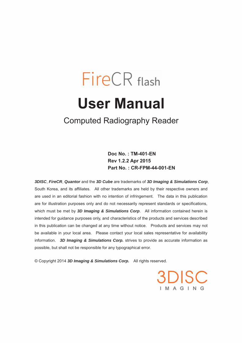
Warnings and Used Symbols To ensure the safety of patients, staff and other persons, any changes to software and hardware delivered by 3D Imaging & Simulations Corp. may only be made with prior written permission from 3D Imaging & Simulations Corp. Please read the respective manuals of the connected software, such as acquisition and diagnostic software, before starting to use the system. The following symbols will be used throughout this manual:
DANGER General prohibition indication. The functionality of the system can be destroyed in the case of incorrect use. If unauthorized changes have been made to delivered system and accessories, the warranty by 3D Imaging & Simulations Corp. becomes void. 3D Imaging & Simulations Corp. will not accept any responsibility or liability for the proper functioning of the product in such a case.
DANGER General mandatory action manual. The functionality of the system can be destroyed in the case of incorrect use. If unauthorized changes have been made to delivered system and accessories, the warranty by 3D Imaging & Simulations Corp. becomes void. 3D Imaging & Simulations Corp. will not accept any responsibility or liability for the improper functioning of the product in such a case.
WARNING The functionality of the system can be limited in the case of incorrect use. Hints that require special attention.
NOTE Notes represent information that is important to know but which do not affect the functionality of the system.

User Manual
FireCR Flash TM-401-EN
5
General Safety Guidelines
All the safety and operating instructions should be read carefully before this device is operated.
This device has been designed and tested to meet strict safety requirements applicable to
medical equipment, and has been supplied in a safe condition. To ensure personnel and
patient safety, the device shall be operated and serviced in compliance with all procedures,
warnings and precautions during all phases of operation and service of this device. Failure to
comply to with safety guidelines may result in injury to service personnel, operator, or patient.
3D Imaging & Simulations Corp. assumes no liability for failure to comply.
If this device is not used as specified, the protection provided by the device could be impaired.
This device must be used in a normal condition only.
Installation, service and operation of this device should only be undertaken by qualified trained
personnel. The operator should study instructions and precautions carefully before starting to
use the device listed here and throughout the manual.
There are no user serviceable parts inside this device. The device should only be opened and
serviced by qualified service personnel. Failure to heed this warning may result in injury to
service personnel or damage to equipment, and void any and all warranties. If there is a
service problem, please contact 3D Imaging & Simulations Corp. or authorized dealer.
Do not spill liquids on the device, and never operate the device in a wet environment.
Keep the device from radiators and heat sources.
Use the device only with accessories supplied with this device.
This device is intended to be grounded. Plug power cord into properly grounded electrical
outlets. This cord is equipped with three-prong plugs to help ensure proper grounding.
This device contains static sensitive components. Proper static handling procedures and
equipment must be used when servicing this device.

User Manual
FireCR Flash TM-401-EN
6
Do not look inside of the device.
If any of the following conditions occur, unplug the device from the electrical outlet and contact
authorized service personnel.
The power cord or power adapter is damaged.
An object has fallen into the device.
The device has been exposed to water.
The device has been dropped or damaged.
The device does not operate correctly when the operating instructions are followed.
Intended Use
This device is a Computed Radiography System and intended for use in producing digital X-Ray
images for general radiography purposes. It comprises of reader, cassette with reusable
imaging plate and workstation software. It scans X-Ray exposed image plate and produces X-
Ray image in digital form. Then, digital image is transferred to workstation for further
processing and routing. This device is intended to be operated in a radiological environment
by qualified staff.
FireCR Flash is not approved for the acquisition of mammographic image data.
User Manual
FireCR Flash TM-401-EN
7
Index of contents
Chapter 1. Introduction .................................................................... 9
Chapter 2. Unpacking ..................................................................... 112.1. Inspection for Damage .................................................................... 112.2. Identify the Components .................................................................. 11
Chapter 3. Setting Up .................................................................... 133.1. Tabletop Mount ............................................................................... 133.2. Wall Mount (Option) ........................................................................ 143.3. Identify Important Features ............................................................. 16
3.3.1. Reader Connecting Part ........................................................... 163.3.2. Reader Status Indication LED .................................................. 173.3.3. Reader Reset Button ................................................................ 17
3.4. Computer Requirements ................................................................ 183.4.1. Recommended Requirement .................................................... 183.4.2. Minimum Requirement ............................................................. 18
3.5. Installation of Acquisition and Diagnostic Software (Option) ........... 183.6. Connect the Cable and Power Cord ............................................... 18
3.6.1. Connect Interface Cable ........................................................... 183.6.2. Connect the Power Cord .......................................................... 193.6.3. Installation Report ..................................................................... 20
Chapter 4. Operating ..................................................................... 214.1. System Specifications .................................................................... 214.2. Operation Conditions ...................................................................... 224.3. Operating Instructions .................................................................... 23
4.3.1. Turn on the Reader ................................................................... 234.3.2. Turn on the Computer ............................................................... 234.3.3. Cassette Insert and Eject ......................................................... 234.3.4. Getting a Scanned Image ......................................................... 234.3.5. Circuit Functions ....................................................................... 24
User Manual
FireCR Flash TM-401-EN
8
Chapter 5. Symbols ....................................................................... 255.1. Manufacturer’s Declaration – Electromagnetic Emission ................ 265.2. Manufacturer’s Declaration - Electromagnetic Immunity ................ 275.3. Guidance and Manufacturer ’s Declaration – Electromagnetic Immunity ..................................................................................................... 305.4. Laser Safety Statement .................................................................. 31
Chapter 6. Warranty and Repair Service ....................................... 326.1. Standard Warranty .......................................................................... 326.2. Repair Service ................................................................................ 326.3. Out of Warranty Repair Service ...................................................... 326.4. Shipping ......................................................................................... 33
Chapter 7. Technical Assistance .................................................... 34

User Manual
FireCR Flash TM-401-EN
9
Chapter 1. Introduction Thank you very much for deciding on FireCR Flash – Computed Radiography Reader. The FireCR Flash System is ideal for a wide range of Computed Radiography examinations in specialty practices such as chiropractors, podiatrists and orthopedists. The FireCR Flash can be configured for nearly every clinical application, and is designed for full DICOM connectivity, and allows user to setup the system to capture high quality X-ray images of any body parts with minimal steps including reading, processing, displaying and sending of the high quality image. All imaging parameters are optimized, resulting in digital images that can be enhanced, enlarged, duplicated, and sent to any location as a DICOM 3.0 file format in seconds with no loss of resolution. Combine the system with reusable phosphor screen equipped FireCR Flash cassettes and portable X-ray equipment, it can be used for X-ray exams everywhere it is needed, e.g. nursing facilities, forensic institutions, employee screenings etc. The FireCR Flash System is ideal for Computed Radiography examinations in busy clinics and specialty practices. Affordable, rugged, compact, lightweight, fast and effective FireCR Flash System enables all imaging functions to be performed with the advanced image management software, a solution that can be adapted most clinical applications. The FireCR Flash Computed Radiography solution with enhanced workflow and improved productivity are the best solution for medium sized healthcare facilities and clinics. The FireCR Flash System complements centralized CR and DR environments such as clinics, ER and OR departments.

User Manual
FireCR Flash TM-401-EN
10
Main Features State-of-the-Art Scanning Mechanism FireCR Flash adopts state-of-the-art scanning mechanisms using high beam delivery efficiency optics module to construct its compact and rigid structure. High Throughput Its unique and patented dual direction scanning mechanism enables to improve the efficiency and high throughput. Scanning Resolution User selectable resolution of 100 m and 200 m allows user to make diagnosis on variable purposes. Detector High sensitive photomultiplier tube equipped in FireCR Flash delivers high gain, wide dynamic range and high speed response for radiographic imaging. Powerful Acquisition and Diagnostic Software Acquisition and Diagnostic Software designed for the FireCR Flash, and its accurate and rapid data processing make the reader more powerful.

User Manual
FireCR Flash TM-401-EN
11
Chapter 2. Unpacking
2.1. Inspection for Damage FireCR Flash is shipped in a custom designed container to protect the reader from external shock. Before unpacking the reader, inspect the shipping container for damage. In case the container is damaged, notify the shipper immediately.
2.2. Identify the Components Identify each of these components.
Part No. Item
CR-FP-41-001 FireCR Flash CR Reader
CR-FP-42-001 Cassette including IP 35cm x 43cm
CR-FP-42-002 Cassette including IP 24cm x 30cm
CR-FPA-02-001 USB 2.0 Interface Cable
CR-FPA-03-00X Power Cord
CR-FPM-44-001 FireCR Flash User Manual
Optional items
Part No. Item
CR-FP-42-003 Cassette including IP 18cm x 24cm
CR-FP-46-001 Wall Mounting Kit for FireCR Flash
CR-FP-05-001 FireKit Field Upgrade Kit
WARNING If the FireCR Flash needs to be returned to manufacturer or one of its representatives, the scanner must be repacked in the original container with all accessories.
User Manual
FireCR Flash TM-401-EN
12
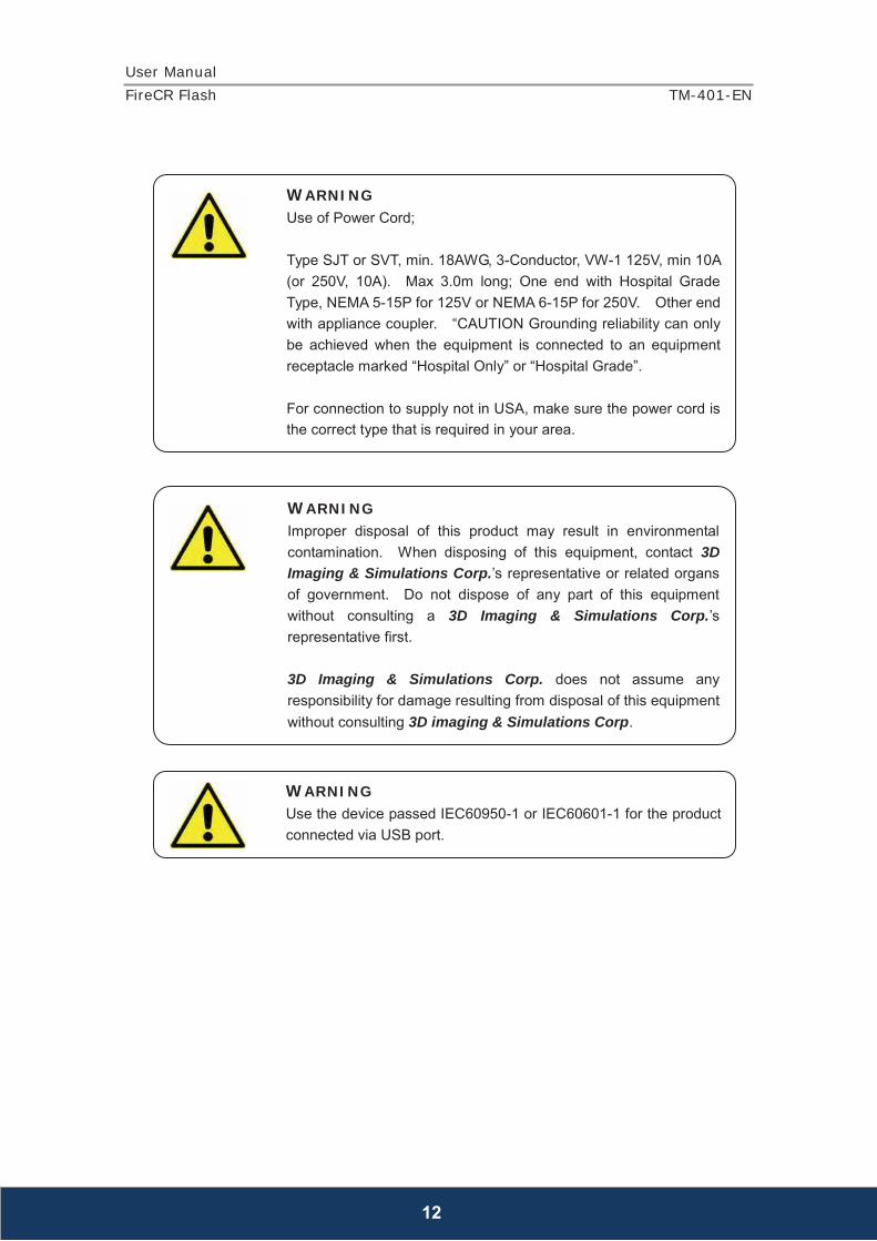
WARNING Use of Power Cord; Type SJT or SVT, min. 18AWG, 3-Conductor, VW-1 125V, min 10A (or 250V, 10A). Max 3.0m long; One end with Hospital Grade Type, NEMA 5-15P for 125V or NEMA 6-15P for 250V. Other end with appliance coupler. “CAUTION Grounding reliability can only be achieved when the equipment is connected to an equipment receptacle marked “Hospital Only” or “Hospital Grade”. For connection to supply not in USA, make sure the power cord is the correct type that is required in your area.
WARNING Improper disposal of this product may result in environmental contamination. When disposing of this equipment, contact 3D Imaging & Simulations Corp.’s representative or related organs of government. Do not dispose of any part of this equipment without consulting a 3D Imaging & Simulations Corp.’s representative first. 3D Imaging & Simulations Corp. does not assume any responsibility for damage resulting from disposal of this equipment without consulting 3D imaging & Simulations Corp.
WARNING Use the device passed IEC60950-1 or IEC60601-1 for the product connected via USB port.
User Manual
FireCR Flash TM-401-EN
13
Chapter 3. Setting Up
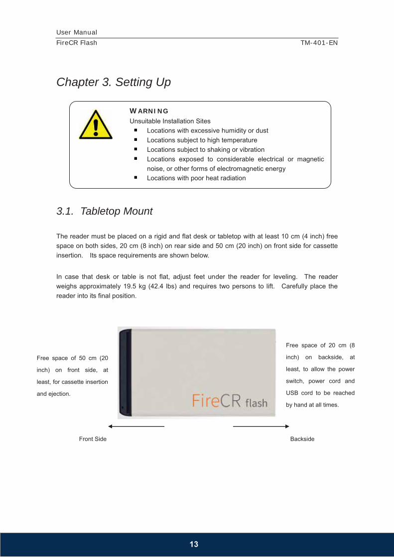
3.1. Tabletop Mount The reader must be placed on a rigid and flat desk or tabletop with at least 10 cm (4 inch) free space on both sides, 20 cm (8 inch) on rear side and 50 cm (20 inch) on front side for cassette insertion. Its space requirements are shown below.
In case that desk or table is not flat, adjust feet under the reader for leveling. The reader weighs approximately 19.5 kg (42.4 lbs) and requires two persons to lift. Carefully place the reader into its final position.
WARNING Unsuitable Installation Sites
Locations with excessive humidity or dust Locations subject to high temperature Locations subject to shaking or vibration Locations exposed to considerable electrical or magnetic
noise, or other forms of electromagnetic energy Locations with poor heat radiation
Free space of 20 cm (8
inch) on backside, at
least, to allow the power
switch, power cord and
USB cord to be reached
by hand at all times.
Free space of 50 cm (20
inch) on front side, at
least, for cassette insertion
and ejection.
Front Side Backside

User Manual
FireCR Flash TM-401-EN
14
3.2. Wall Mount (Option) The FireCR Flash can be mounted on the wall to save space occupancy. When purchasing the wall mount kit, a detailed installation guide and all parts necessary for assembly are provided.
DANGER Never place the reader on the floor. Sliding the reader may result in internal damage or misalignment of the optics. Install in a location that is level and stable. Installation in an unsuitable location can cause accident, or deterioration in image quality.
WARNING Sliding the reader may result in internal damage or misalignment of the optics. External vibration or shock during scanning may affect image quality. The scanner must be placed on rigid, flat and reinforced desk or tabletop.
DANGER Do not place anything on top of the scanner.
WARNING This equipment may be interfered or interfere by electromagnetic or other interference. Assure a distance of minimum 1.0 m with neighboring equipment.

User Manual
FireCR Flash TM-401-EN
15
NOTE Refer to Wall Mount Installation Guide provided with Wall Mount Installation Kit.
DANGER Only authorized or trained personnel should set wall mount installation.
Free space of 10 cm
(4 inch) on both
sides, at least.
Front Side
Back Side
Free space of 20 cm (8 inch) on back side, at least, to allow the
power switch, power cord and USB cord to be reached by hand
at all times.
Free space of 50 cm (20 inch) on top side, at least, for cassette
insertion and ejection.

User Manual
FireCR Flash TM-401-EN
16
3.3. Identify Important Features Look over the reader and features shown in this section. User will need to know where these features are when user operates the reader in later chapters.
3.3.1. Reader Connecting Part
DANGER Install the wall mount on a solid wall perpendicular to the floor. When attaching to other building materials, please contact your local dealer. If installed on a slanted wall, it may fall and result in severe injury.
DANGER 3D Imaging & Simulations Corp. is not liable for product damage or personal injury when the user fails to follow the product installation instruction.
WARNING Pulling, pushing, or climbing on the system may cause the system fall.
USB 2.0 Port Power Inlet Power Switch Ethernet Port
User Manual
FireCR Flash TM-401-EN
17
3.3.2. Reader Status Indication LED Indication LED shows the status of the reader as described below.
LED Status Remark
Green Blue On System On
On Ready to Scan Cassette is in initial position, and ready to scan.
Blinking Scanning Blinking Erasing
Blinking Blinking Error
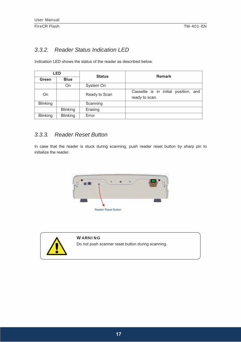
3.3.3. Reader Reset Button In case that the reader is stuck during scanning, push reader reset button by sharp pin to initialize the reader.
WARNING Do not push scanner reset button during scanning.
Reader Reset Button
User Manual
FireCR Flash TM-401-EN
18
3.4. Computer Requirements
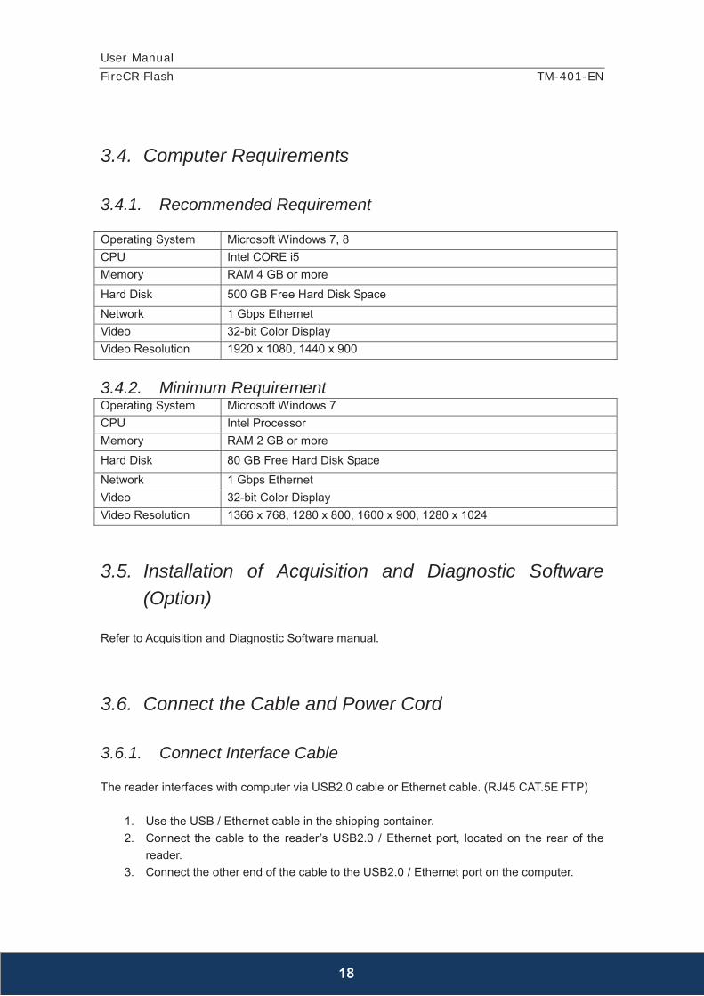
3.4.1. Recommended Requirement Operating System Microsoft Windows 7, 8 CPU Intel CORE i5 Memory RAM 4 GB or more Hard Disk 500 GB Free Hard Disk Space Network 1 Gbps Ethernet Video 32-bit Color Display Video Resolution 1920 x 1080, 1440 x 900
3.4.2. Minimum Requirement Operating System Microsoft Windows 7 CPU Intel Processor Memory RAM 2 GB or more Hard Disk 80 GB Free Hard Disk Space Network 1 Gbps Ethernet Video 32-bit Color Display Video Resolution 1366 x 768, 1280 x 800, 1600 x 900, 1280 x 1024
3.5. Installation of Acquisition and Diagnostic Software (Option)
Refer to Acquisition and Diagnostic Software manual.
3.6. Connect the Cable and Power Cord
3.6.1. Connect Interface Cable The reader interfaces with computer via USB2.0 cable or Ethernet cable. (RJ45 CAT.5E FTP)
1. Use the USB / Ethernet cable in the shipping container. 2. Connect the cable to the reader’s USB2.0 / Ethernet port, located on the rear of the
reader. 3. Connect the other end of the cable to the USB2.0 / Ethernet port on the computer.

User Manual
FireCR Flash TM-401-EN
19
3.6.2. Connect the Power Cord
1. Connect the power cord to the reader, located on the rear side. 2. Connect the other end of the cord to a grounded power outlet.
DANGER This equipment is indoor use only and all the communication wirings are limited to inside of the building.
DANGER This equipment must only be connected to supply mains with protective earth. Use only a three-wire cord that has grounding. This is a safety feature. If you are unable to insert the plug into the outlet, contact your electrician to replace your obsolete outlet. Do not defeat the safety purpose of the grounding-type plug.
WARNING Socket-outlet shall be installed near the device and shall be easily accessible. Do not place the device where difficult to access to appliance inlet. Do not unplug the power cord or turn the power switch off during scanning.
DANGER Do not use any power cord other than the power cord included with the system. Doing so may lead to fire, electrical shock, or electrocution.
WARNING Do not pull out the USB / Ethernet cable during scanning.
User Manual
FireCR Flash TM-401-EN
20
3.6.3. Installation Report After installation of the reader, fill in Installation Report from (Appendix I) and send to 3D Imaging & Simulations Corp. service department by fax or e-mail.
Fax : +82-42-931-2299 E-mail : [email protected]

User Manual
FireCR Flash TM-401-EN
21
Chapter 4. Operating
4.1. System Specifications
Sampling Pixel Pitch Standard 200um High 100um
Pixel Matrix (IP 35cm x 43cm) Standard 1750 x 2150 High 3500 x 4300
Pixel Matrix (IP 24cm x 30cm) Standard 1200 x 1500 High 2400 x 3000
Pixel Matrix (IP 18cm x 24cm) Standard 900 x 1200 High 1800 x 2400
Accepted Cassette Size 35cm x 43cm, 24cm x 30cm, 18cm x 24cm
AD Convert Resolution 16 bit Eraser Embedded Computer Interface USB 2.0 / Ethernet
Dimensions 456 x 803 x 137mm 17.9 x 31.6 x 5.4inch
Weight 19.5kg 42.4lbs
Power Requirement 100 ~ 240V / 50 ~ 60Hz
System Configuration Tabletop or Wall Mount Image File Format DICOM 3.0 * Specifications subject to change without notice. ** Specific results may vary since operating conditions fluctuate.
User Manual
FireCR Flash TM-401-EN
22
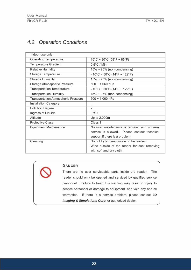
4.2. Operation Conditions
Indoor use only Operating Temperature 15 C ~ 30 C (59 F ~ 86 F) Temperature Gradient 0.5 C / Min Relative Humidity 15% ~ 95% (non-condensing) Storage Temperature - 10 C ~ 50 C (14 F ~ 122 F) Storage Humidity 15% ~ 95% (non-condensing) Storage Atmospheric Pressure 500 ~ 1,060 hPa Transportation Temperature - 10 C ~ 50 C (14 F ~ 122 F) Transportation Humidity 15% ~ 95% (non-condensing) Transportation Atmospheric Pressure 500 ~ 1,060 hPa Installation Category II Pollution Degree 2 Ingress of Liquids IPX0 Altitude Up to 2,000m Protective Class Class 1 Equipment Maintenance No user maintenance is required and no user
service is allowed. Please contact technical support if there is a problem.
Cleaning Do not try to clean inside of the reader. Wipe outside of the reader for dust removing with soft and dry cloth.
DANGER There are no user serviceable parts inside the reader. The
reader should only be opened and serviced by qualified service
personnel. Failure to heed this warning may result in injury to
service personnel or damage to equipment, and void any and all
warranties. If there is a service problem, please contact 3D
Imaging & Simulations Corp. or authorized dealer.

User Manual
FireCR Flash TM-401-EN
23
4.3. Operating Instructions
4.3.1. Turn on the Reader Turn on the reader. Power switch is on the rear side of the reader.
4.3.2. Turn on the Computer Turn on the computer. Acquisition and Diagnostic Software must be installed before operate the reader.
4.3.3. Cassette Insert and Eject Insert the cassette to the entrance of the reader and push gently until it reaches to the protection wall inside of the reader. Green indication LED is on when the cassette is inserted correctly. Insertion direction of the cassette must be parallel to the reader. Cassette can be ejected when scanning and erasing are completed. Gently pull back the cassette and ejection direction of the cassette must be parallel to the reader.
4.3.4. Getting a Scanned Image To getting a scanned image, refer to Acquisition and Diagnostic Software manual.
DANGER This device uses laser. Avoid looking inside of the scanner.
WARNING Do not insert the cassette in wrong direction or upside down when it is being inserted. Cassette insertion direction is marked on the cassette.
User Manual
FireCR Flash TM-401-EN
24
4.3.5. Circuit Functions
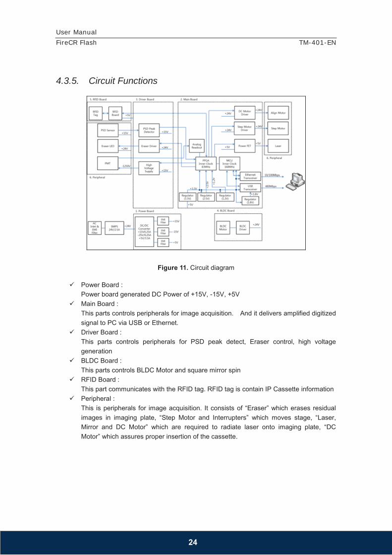
Figure 11. Circuit diagram
Power Board :
Power board generated DC Power of +15V, -15V, +5V
Main Board : This parts controls peripherals for image acquisition. And it delivers amplified digitized signal to PC via USB or Ethernet.
Driver Board : This parts controls peripherals for PSD peak detect, Eraser control, high voltage generation
BLDC Board : This parts controls BLDC Motor and square mirror spin
RFID Board : This part communicates with the RFID tag. RFID tag is contain IP Cassette information
Peripheral : This is peripherals for image acquisition. It consists of “Eraser” which erases residual images in imaging plate, “Step Motor and Interrupters” which moves stage, “Laser, Mirror and DC Motor” which are required to radiate laser onto imaging plate, “DC Motor” which assures proper insertion of the cassette.
User Manual
FireCR Flash TM-401-EN
25
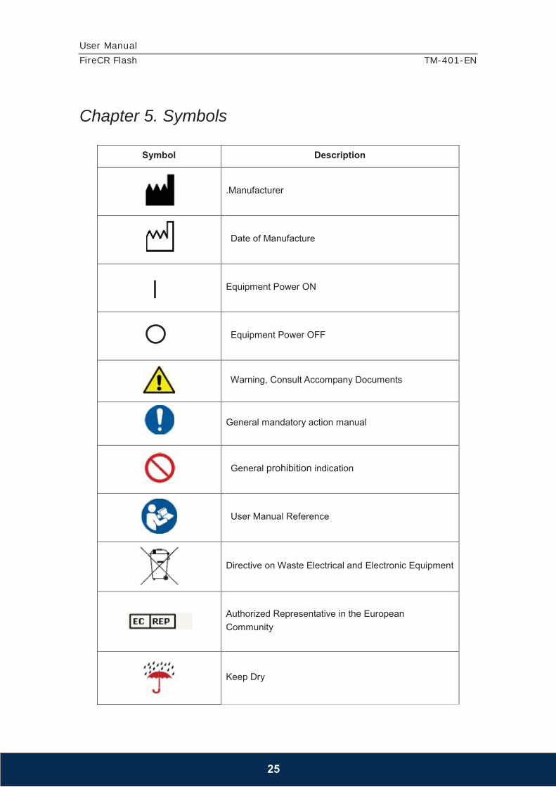
Chapter 5. Symbols
Symbol Description
.Manufacturer
Date of Manufacture
Equipment Power ON
Equipment Power OFF
Warning, Consult Accompany Documents
General mandatory action manual
General prohibition indication
User Manual Reference
Directive on Waste Electrical and Electronic Equipment
Authorized Representative in the European Community
Keep Dry
User Manual
FireCR Flash TM-401-EN
26
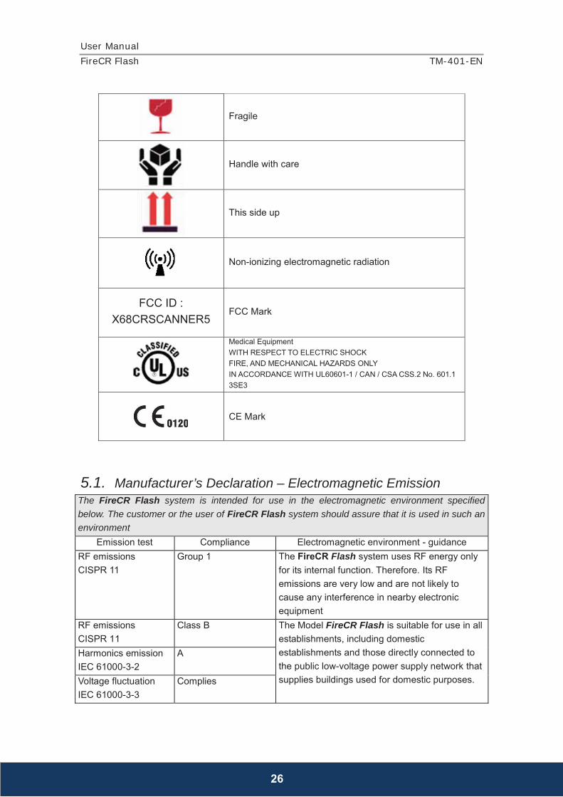
Fragile
Handle with care
This side up
Non-ionizing electromagnetic radiation
FCC ID : X68CRSCANNER5
FCC Mark
Medical Equipment WITH RESPECT TO ELECTRIC SHOCK FIRE, AND MECHANICAL HAZARDS ONLY IN ACCORDANCE WITH UL60601-1 / CAN / CSA CSS.2 No. 601.1 3SE3
CE Mark
5.1. Manufacturer’s Declaration – Electromagnetic Emission The FireCR Flash system is intended for use in the electromagnetic environment specified below. The customer or the user of FireCR Flash system should assure that it is used in such an environment
Emission test Compliance Electromagnetic environment - guidance RF emissions CISPR 11
Group 1 The FireCR Flash system uses RF energy only for its internal function. Therefore. Its RF emissions are very low and are not likely to cause any interference in nearby electronic equipment
RF emissions CISPR 11
Class B The Model FireCR Flash is suitable for use in all establishments, including domestic establishments and those directly connected to the public low-voltage power supply network that supplies buildings used for domestic purposes.
Harmonics emission IEC 61000-3-2
A
Voltage fluctuation IEC 61000-3-3
Complies
User Manual
FireCR Flash TM-401-EN
27
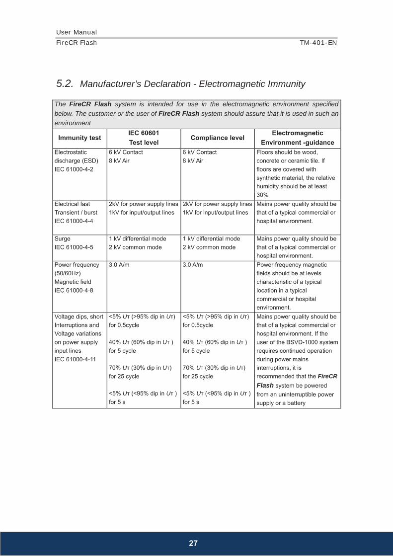
5.2. Manufacturer’s Declaration - Electromagnetic Immunity
The FireCR Flash system is intended for use in the electromagnetic environment specified below. The customer or the user of FireCR Flash system should assure that it is used in such an environment
Immunity test IEC 60601 Test level
Compliance level Electromagnetic
Environment -guidance Electrostatic discharge (ESD) IEC 61000-4-2
6 kV Contact 8 kV Air
6 kV Contact 8 kV Air
Floors should be wood, concrete or ceramic tile. If floors are covered with synthetic material, the relative humidity should be at least 30%
Electrical fast Transient / burst IEC 61000-4-4
2kV for power supply lines 1kV for input/output lines
2kV for power supply lines 1kV for input/output lines
Mains power quality should be that of a typical commercial or hospital environment.
Surge IEC 61000-4-5
1 kV differential mode 2 kV common mode
1 kV differential mode 2 kV common mode
Mains power quality should be that of a typical commercial or hospital environment.
Power frequency (50/60Hz) Magnetic field IEC 61000-4-8
3.0 A/m 3.0 A/m Power frequency magnetic fields should be at levels characteristic of a typical location in a typical commercial or hospital environment.
Voltage dips, short Interruptions and Voltage variations on power supply input lines IEC 61000-4-11
<5% Uт (>95% dip in Uт) for 0.5cycle 40% Uт (60% dip in Uт ) for 5 cycle 70% Uт (30% dip in Uт) for 25 cycle <5% Uт (<95% dip in Uт ) for 5 s
<5% Uт (>95% dip in Uт) for 0.5cycle 40% Uт (60% dip in Uт ) for 5 cycle 70% Uт (30% dip in Uт) for 25 cycle <5% Uт (<95% dip in Uт ) for 5 s
Mains power quality should be that of a typical commercial or hospital environment. If the user of the BSVD-1000 system requires continued operation during power mains interruptions, it is recommended that the FireCR Flash system be powered from an uninterruptible power supply or a battery

User Manual
FireCR Flash TM-401-EN
28
Conducted RF IEC 61000-4-6
3 Vrms 150 kHz to 80 MHz
3 Vrms 150 kHz to 80 MHz
Portable and mobile RF communications equipment should be used no closer to any part of the FireCR Flash system, including cables, than the recommended separation distance calculated from the equation applicable to the frequency of the transmitter.
Recommended separation distance
Radiated RF IEC 61000-4-3
3 V/m 80.0 MHz to 2.5 GHz
3 V/m 80.0 MHz to 2.5 GHz
Recommended separation distance
Where P is the maximum output power rating of the transmitter in watts (W) according to the transmitter manufacturer and d is the recommended separation distance in meters (m). Field strengths from fixed RF transmitters, as deter-mined by an electromagnetic site survey, (a) Should be less than the compliance level in each frequency range (b).
Interference may occur in the vicinity of equipment marked with the following symbol:
Note 1) Uт is the A.C. mains voltage prior to application of the test level. Note 2) At 80 MHz and 800 MHz, the higher frequency range applies. Note 3) These guidelines may not apply in all situations. Electromagnetic propagation is affected by absorption and reflection from structures, objects and people.

User Manual
FireCR Flash TM-401-EN
29
a Field strengths from fixed transmitters, such as base stations for radio (cellular/cordless) telephones and land mobile radios, amateur radio, AM and FM radio broadcast and TV broadcast cannot be predicted theoretically with accuracy. To assess the electromagnetic environment due to fixed RF transmitters, an electromagnetic site survey should be considered. If the measured field strength in the location in which the EUT is used exceeds the applicable RF compliance level above, the EUT should be observed to verifynormal operation. If abnormal performance is observed, additional measures may be necessary, such as re-orienting or relocating the EUT. b Over the frequency range 150 kHz to 80 MHz, field strengths should be less than [V1] V / m. Recommended Separation Distances Between Portable and Mobile RF Communications Equipment and the FireCR Flash system. The FireCR Flash system is intended for use in an electromagnetic environment in which radiated RF disturbances are controlled. The user of the FireCR Flash system can help prevent electromagnetic interference by maintaining a minimum distance between portable and mobile RF communications equipment (transmitters) and the FireCR Flash system as recommended below, according to the maximum output power of the communications equipment.
Rated maximum output power (W) of transmitter
Separation distance (m) according to frequency of transmitter
150 kHz to 80 MHz 80 MHz to 800 MHz 800 MHz to 2.5
GHz 0.01 0.12 0.12 0.23 0.1 0.37 0.37 0.74 1 1.17 1.17 2.33
10 3.70 3.70 7.37 100 11.70 11.70 23.30
For transmitters rated at a maximum output power not listed above, the recommended separation distance (d) in meters (m) can be estimated using the equation applicable to the frequency of the transmitter, where P is the maximum output power rating of the transmitter in watts (W) according to the transmitter manufacturer. Note 1: At 80 MHz and 800 MHz, the separation distance for the higher frequency range applies. Note 2: These guidelines may not apply in all situations. Electromagnetic propagation is affected by absorption and reflection from structures, objects, and people.
Immunity and Compliance Level Immunity test IEC 60601 Test Level Actual Immunity Level Compliance Level Conducted RF IEC 61000-4-6
3 Vrms, 150 kHz to 80 MHz
3 Vrms, 150 kHz to 80 MHz
3 Vrms, 150 kHz to 80 MHz
Radiated RF IEC 61000-4-3
3 V/m, 80 MHz to 2.5 GHz
3 V/m, 80 MHz to 2.5 GHz
3 V/m, 80 MHz to 2.5 GHz

User Manual
FireCR Flash TM-401-EN
30
5.3. Guidance and Manufacturer ’s Declarat ion –
Electromagnetic Immunity
The FireCR Flash system is intended for use in the electromagnetic environment specified below. The customer or the user of FireCR Flash system should assure that it is used in such an environment
Immunity test IEC 60601 Test level
Compliance level Electromagnetic environment -guidance
Conducted RF IEC 61000-4-6
3 Vrms 150 kHz to 80MHz
3 Vrms 150 kHz to 80 MHz
FireCR Flash system must be used only in a shielded location with a minimum RF shielding effectiveness and, for each cable that enters the shielded location with a minimum RF shielding effectiveness and, for each cable that enters the shielded location
Radiated RF IEC 61000-4-3
3 V/m 80.0 MHz to 2.5GHz
3 V/m 80.0 MHz to 2.5GHz
Field strengths outside the shielded location from fixed RF transmitters, as determined by an electromagnetic site survey, should be less than 3V/m.a Interference may occur in the vicinity of equipment marked with the following symbol:
Note 1) These guidelines may not apply in all situations. Electromagnetic propagation is affected by absorption and reflection from structures, objects and people. Note 2) It is essential that the actual shielding effectiveness and filter attenuation of the shielded location be verified to assure that they meet the minimum specification. a- Field strengths from fixed transmitters, such as base stations for radio (cellular/cordless) telephones and land mobile radios, amateur radio, AM and FM radio broadcast and TV broadcast cannot be predicted theoretically with accuracy. To assess the electromagnetic environment due to fixed RF transmitters, an electromagnetic site survey should be considered. If the measured field strength outside the shielded location in which the EUT is used exceeds 3V/m, the EUT should be observed to verify normal operation. If abnormal performance is observed, additional measures may be necessary, such as relocating the EUT or using a shielded location with a higher RF shielding effectiveness and filter attenuation.
User Manual
FireCR Flash TM-401-EN
31
5.4. Laser Safety Statement The Computed Radiography Reader is Certified in the U.S. to Conform to the Requirements of DHHS 21 CFR, chapter 1 Subchapter J for Class I(1) Laser Products, and Elsewhere is Certified as a Class I(1) Laser Product Conforming to the Requirements of IEC 60825-1 : 2007. Class I(1) Laser Products are not Considered to be Hazardous. The Laser System and Computed Radiography Reader are Designed so there is never any Human Access to Laser Radiation above a Class I(1) level during normal Operation, user Maintenance or Prescribed Service Condition. • Wavelength : 658 nm (Typ.) • Beam Divergence - Paraller : 9.5 degrees (-2.5/+2.5) - Perpendicular : 17 degrees (-3/+3) • Maximum Power of Energy Output : 80 mW (CW)
WARNING Never operate or service the product with the protective cover removed from Laser/Reader assembly. The reflected beam, although invisible, can damage your eyes. When using this product, these basic safety precautions should always be followed to reduce risk of fire, electric shock and personal injury
Warning Use of controls or adjustments or performance of procedures other than
those specified herein may result in hazardous radiation exposure

User Manual
FireCR Flash TM-401-EN
32
Chapter 6. Warranty and Repair Service
6.1. Standard Warranty 3D Imaging & Simulations Corp. warrants its non-consumable hardware products to be free from defects in materials and workmanship. The warranty covers the cost of parts and labor to repair the product. Please keep the shipping container for future use. Products returned to the factory for repair should be properly packaged. To obtain warranty service, follow the procedure described in the Repair Service section. Failure to do so will cause long delays and additional expense to the customer. The warranty is valid when the product is used for its intended purpose and does not cover products which have been modified without written permission from 3D Imaging & Simulations Corp., or which have been damaged by abuse, accident or connection to incompatible equipment. This warranty is in lieu of all other warranties, expressed or implied.
6.2. Repair Service The company reserves the right to cease providing repair maintenance, parts and technical support for its non-consumable hardware products five years after a product is discontinued. Technical support for old versions of software products will cease 12 months after they are upgraded or discontinued.
6.3. Out of Warranty Repair Service Out of warranty repair service is available in selected geographical locations. Contact the supplier for current terms and rates.

User Manual
FireCR Flash TM-401-EN
33
6.4. Shipping The FireCR Flash is a solidly built system designed to survive shipping around the world. However, in order to avoid damage during shipping, the FireCR Flash must be properly packaged. In general, the best way to package the FireCR Flash is in the original factory container. If this is no longer available, we recommend that user carefully wraps the FireCR Flash in at least 75 mm (3 inch) of foam or bubble pack sheeting. The wrapped device should then be placed in a sturdy cardboard carton. Mark the outside of the box with word FRAGILE and an arrow showing which way is up. We do not recommend using loose foam pellets to protect the FireCR Flash. If the carton is dropped by the shipper, there is a good chance that the device will shift within the loose pellet packing and be damaged. If user needs to ship the FireCR Flash to another location, or back to the factory, and user does not have a means to adequately package it, user can order additional shipping container. This may seem an expense user would like to avoid, but it is inexpensive compared to the cost of repairing an instrument that has sustained shipping damage. It is user’s responsibility to package the system properly before shipping. If the packaging is inadequate, and the system is damaged during shipping, the shipper will not honor user’s claim for compensation.
User Manual
FireCR Flash TM-401-EN
34
Chapter 7. Technical Assistance If user has any questions about installing or using the device, contact your 3D Imaging & Simulations Corp representative or your local dealer.
3D Imaging & Simulations Corp. Bldg.1, 48, Yuseong-daero 1184 beon-gil, Yuseong-gu, Daejeon, 305-345 Korea Tel : 82-42-931-2100 Fax : 82-42-931-2299 www.3DISCimaging.com

User Manual
FireCR Flash TM-401-EN
35
Appendix I
Installation Report Please complete this report at the time of installation and submit the completed form signed by customer to:
Fax : +82-42-931-2299 E-mail : [email protected]
Date of Installation : Customer Information Hospital / Institute Name Address Tel Fax E-mail Installer Information Company Name Address Tel Fax E-mail System Information Model FireCR Flash CR Reader System S/N Installer’s Signature: Date: Customer’s Signature: Date: