Fire protection - Koolair · Dampers incorporating a TH-70 fusible link and/or shunt or...
125
Fire protection www.koolair.com
Transcript of Fire protection - Koolair · Dampers incorporating a TH-70 fusible link and/or shunt or...
Fire
protection
www.koolair.com

RPK SCFR SCFC BDK
SMLD CEVH SCDC CEVH-1P GRAPHIC CONSOLE
Rectangular and circularfire dampers
Smoke extract dampers KOOLCOM fire dampermonitoring system
Circular terminalfire damper Smoke extract louvre
Fire protection
Fire protection
CONTENTS
Rectangular and circular fire dampers 2BDK Circular terminal fire damper 34Intumescent louvres for air transfer 40SMLD Smoke extract dampers 44CEVH Smoke extract dampers 55CEVH-1P Smoke extract dampers 65RPK Smoke extract louvre 78SCDC Smoke Extract Dampers 83KOOLCOM Fire damper monitoring system 91UL Approved fire dampers and smoke dampers 110
1
Rectangular and circular fire dampers
CONTENTS
Description 3Declared performance 5Applications 7Model and dimensions 9Accessories 14Installation 15Operating Mechanisms 20Special finishes 23Technical data 24Coding 33
Fire protection2

Rectangular and circular firedampers
DescriptionKOOLAIR rectangular fire dampers, models SCFR-PD,SCFR-GD, SFR3K1GT and circular fire dampers, modelsSCFC-PD and SCFC-GD, are approved in accordance withthe Technical Building Code according to test standard UNEEN 1366-2 and classified according to EN 13501-3.Fire dampers close automatically to prevent fire and smoke fromspreading through ventilation ductwork to adjacent firecompartments.The frame consists of a single sheet of sheet metal with aninternal recess reinforced by a slot sheet metal support thatprevents a thermal bridge.The blade is made of a heat-resistant material with athickness that varies depending on the model, intumescentjoints and a perimeter seal.Symmetrical dampers are designed to be installed in vertical orhorizontal enclosures irrespective of the direction of the airflow.Damper closure is operated by the breaking or smelting of abimetallic fusible link (-TH70) when the temperature exceeds72 ºC.It is reset manually in all instances except when incorporating aservomotor with return spring and a thermoelectric fusible linkcalibrated at 72 ºC.All dampers comply with requirements of the cold smokeleakage standard (-S).
OperationThe components of the manual operating mechanism are madeof zinc plated steel and are housed in a plastic enclosure (manualreset).The operating mechanism acts on the blade through a reversepulley and does not act directly on the blade shaft, which servesonly as a pivot. The blade operating mechanism therefore hasgreater solidity and reliability.The mechanism is offset from the blade shaft, allowing accessto the unit for maintenance and testing.The mechanism housing is evolutive, i.e. all the operatingoptions can be interchanged without having to send it to thefactory.Dampers incorporating a TH-70 fusible link and/or shunt orundervoltage release require a manual “on-site” reset devicethat allows the damper to be reset (opening) after it has beenclosed. Dampers with electric motors can be reset remotely bymeans of an electrical supply (24V or 230V).
SCFR-PD with motor
SCFC-PD with manual operation with fixing strips (optional)
Fire protection 3
Circular fire dampers
Fire protection
StandardsThe dampers are approved in accordance with European Test Standard UNE-EN 1366-2 and Europeanclassification standard UNE-EN 13501-3, where:
(E) Integrity(I) Isolation(ho) Installed in Horizontal slab. Mounted in horizontal enclosure.(ve) Installed in wall or stud wall. Mounted in vertical enclosure.(i ↔ o) Symmetric (independent of airflow direction). Suitable for fire in both directions (interior-exterior andexterior-interior)(S) Airtightness. Leakage through the damper closing blade <200 m3/h*m2
Option for fire dampers to be supplied with airtightness C to comply with EN 1751.
Motor-driven fire dampers can be integrated into the building management system (BMS) and/or fire panel with theKOOLCOM system from KOOLAIR.
To guarantee the correct fire damper operation, it is essential to read and follow the recommendations in theinstallation and operation manual. In addition, the installation must comply with all current national standards.
Further information and updates, as well as the installation and operating manual, can be found on our website(www.koolair.com).
CE MarkingKoolair fire dampers carry the CE marking in compliance with RPC-305/2011/EU, according to EN15650:2010.
NF MarkingThe SCFR-PD, SCFR-GD, SCFC-PD and SCFC-GD models are certified under NF (NF264 Certification Standard,NF S 61-937-5 fire dampers).
4

L: 200 → 800H: 100 → 600
d = 150 mmρ = 1900 kg/m³
El-120 (ve i↔o) S(500 Pa)
L: 200 → 800H: 100 → 600
d = 150 mmρ = 2000 kg/m³
EI-180 (ho i↔o) S(500 Pa)
L: 200 → 800H: 100 → 600 d ≥ 100 mm EI-120 (ve i↔o) S
(500 Pa)
L: 850 → 1500H: 200 → 800
d = 150 mmρ = 1900 kg/m³
El-120 (ve i↔o) S(500 Pa)
L: 850 → 1500H: 200 → 800
d = 150 mmρ = 2400 kg/m³
EI-120 (ho i↔o) S(500 Pa)
L: 200 → 1500H: 200 → 800
d = 150 mmρ = 1900 kg/m³
El-180 (ve i↔o) S(300 Pa)
SCFR-PDCPR-2245-16
SCFR-GDCPR-2591-16
SFR3K1GTCPR-1493-14
Dimensions(mm)
Dimensions(mm)
Constructiondetails
Constructiondetails
Installationlocation
Installationlocation
Installationlocation
Installation
Installation
Installation
Classification
Classification
Classification
Mortar
Mortar
Mortar
Mortar
Mortar
Plasterboard
Floor slab
Floor slab
Stud wall
Brick Wall
Brick Wall
Brick Wall
Fire protection
Declared performance
Rectangular fire dampers
Dimensions(mm)
Constructiondetails
The performance specifications of our range of fire dampers (rectangular and circular) are shown in the table below.
5

Ø: 100 → 355 d = 150 mmρ = 1900 kg/m³
El-120 (ve i↔o) S(500 Pa)
Ø: 100 → 355 d = 150 mmρ = 2000 kg/m³
EI-180 (ho i↔o) S(500 Pa)
Ø: 100 → 355 d ≥ 100 mm EI-120 (ve i↔o) S(500 Pa)
Ø: 400 → 800 d = 150 mmρ = 2000 kg/m³
El-180 (ve i↔o) S(500 Pa)
Ø: 200 → 630 d = 150 mm
ρ = 2100 kg/m³EI-180 (ho i↔o) S
(500 Pa)
SCFC-PDCPR-2244-16
SCFC-GDCPR-2592-16
Declared performance
Circular fire dampers
Details of supporting structure, tested on Stud wall (plasterboard):• Fire resistance rating: EI 90.• 2 sheets of laminated fireproof plasterboard ref. KNAUF cortafuego DF thickness 12.5 mm.• Rock wool panel ref. ProRox SL960 (ROCKWOOL).• 2 sheets of laminated fireproof plasterboard ref. KNAUF cortafuego DF thickness 12.5 mm.• 48 mm U-shaped channels and uprights in 400 mm modules.
Key L: Length H: Height Ø: Diameter d: Wall thickness p: Density
Constructiondetails
Installationlocation Installation Classification
Mortar
Mortar
Mortar
Mortar
Plasterboard
BrickWall
BrickWall
Floor slab
Floor slab
Stud wall
Dimensions(mm)
Constructiondetails
Installationlocation Installation ClassificationDimensions
(mm)
Fire protection6

L (mm)200 300 400 500 600 700 800 900 1000 1100 1200 1300 1400 1500
200300400500600700800
H (m
m)
SFR3K1GT
L (mm)200 300 400 500 600 700 800 850 900 1000 1100 1200 1300 1400 1500
100200300400500600650700800
H (m
m) SCFR-PD
SCFR-GD
SCFR-GD
L (mm)200 300 400 500 600 700 800
100200300400500600
H (m
m)
SCFR-PD
Applications
FIXED WALL EI-180 EI-180 (ve i↔o) S (RECTANGULAR)
FIXED WALL EI-120 (ve i↔o) S (RECTANGULAR)
The length and height of all models of rectangular fire dampers increases in 50mm increments.
STUD WALL EI-120 (ve i↔o) S (RECTANGULAR)
Fire protection 7

L (mm)200 300 400 500 600 700 800 850 900 1000 1100 1200 1300 1400 1500
100200300400500600650700800
H (m
m)
SCFR-PD(EI-180-S)
SCFR-GD(EI-120-S)
Ø (mm)100 125 160 200 250 315 355
SCFC-PD
Ø (mm)100 125 160 200 250 315 355 400 450 500 560 630 650 700 710 750 800
SCFC-GD (EI-120-S)SCFC-PD (EI-120-S)SCFC-GD (EI-180-S)
Ø (mm)100 125 160 200 250 315 355 400 450 500 560 630
SCFC-PD SCFC-GD
Applications
SLAB EI-120 (ho i↔o) S / EI-180 (ho i↔o) S (RECTANGULAR)
STUD WALL EI-120 (ve i↔o) S (CIRCULAR)
FIXED WALL EI-120 (ve i↔o) S / EI-180 (ve i↔o) S (CIRCULAR)
SLAB EI-120 (ho i↔o) S / EI-180 (ho i↔o) S (CIRCULAR)
Fire protection8

H S1 S2100 - -150 - -200 - -250 - -300 - 14350 - 39400 - 64450 - 89500 - 114550 10 139600 35 164
1 1 1
2
2
2
3
3
34
44
5
5
56
6
6
SCFR-PD Model and dimensions
SCFR-PD fire dampers are available in standard sizes (duct size) with a length (L dimension) from 200 to 800 mmincreasing in 50mm increments and a height (dimension H) from 100 to 600 mm increasing in 50mm increments.
1- Galvanised steel frame2- Damper blade3- Mechanism/motor housing4- Intumescent seal5- Fixing lug for installing in slab floor (optional)6- 30 mm flange
Drive shaft
Fire protection 9
1
2
34
5
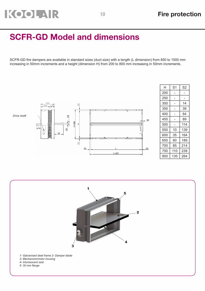
H S1 S2200 - -250 - -300 - 14350 - 39400 - 64450 - 89500 - 114550 10 139600 35 164650 60 189700 85 214750 110 239800 135 264
SCFR-GD Model and dimensions
1- Galvanised steel frame 2- Damper blade3- Mechanism/motor housing4- Intumescent seal5- 30 mm flange
Drive shaft
SCFR-GD fire dampers are available in standard sizes (duct size) with a length (L dimension) from 850 to 1500 mmincreasing in 50mm increments and a height (dimension H) from 200 to 800 mm increasing in 50mm increments.
Fire protection10

H S1 S2200 - -250 - -300 - 9350 - 34400 - 59450 - 84500 - 109550 4 134600 29 159650 54 184700 79 209750 104 234800 129 259
1
2
3 4
56
1
2
35
6
4
SFR3K1GT Model and dimensions
SFR3K1GT fire dampers are available in standard sizes (duct size) with a length (L dimension) from 200 to 1500 mmincreasing in 50mm increments and a height (dimension H) from 200 to 800 mm increasing in 50mm increments.
Drive axis
1- Galvanised steel frame2- Blade3- Mechanism/motor housing4- Intumescent seal5- Fixing lug for installing in slab (optional)6- 30 mm flange
Fire protection 11

S2100 -125 -160 -200 -250 -315 25355 50
1
2
3
5
1
3
2
1
3
24 4
4
SCFC-PD Model and dimensions
The standard dimensions (duct dimensions) of SCFC-PD fire dampers are: 100, 125, 160, 200, 250, 315 and 355 mm.
Drive shaft
Ø nominal - 2
1- Galvanised steel frame2- Blade3- Mechanism/motor housing4- Intumescent seal5- Fixing lug for installing in slab (optional)
Ø NOMINAL
Fire protection12

S1 S2400 - 73450 - 98500 - 123560 3 153630 38 188650 48 198700 73 223710 78 228750 98 248800 123 273
1
3
2
5
1
3
2
5
4 4
SCFC-GD Model and dimensions
The standard dimensions (duct dimensions) of SCFC-GD fire dampers are: 400, 450, 500, 560, 630, 650, 700, 710, 750and 800 mm.
Ø n
omin
al -
2
Ø n
omin
al +
48
Drive shaft
1- Galvanised steel frame2- Damper blade3- Mechanism/motor housing4- Intumescent seal5- Fixing lug for installing in slab (optional)
Ø NOMINAL
Fire protection 13
Accessories
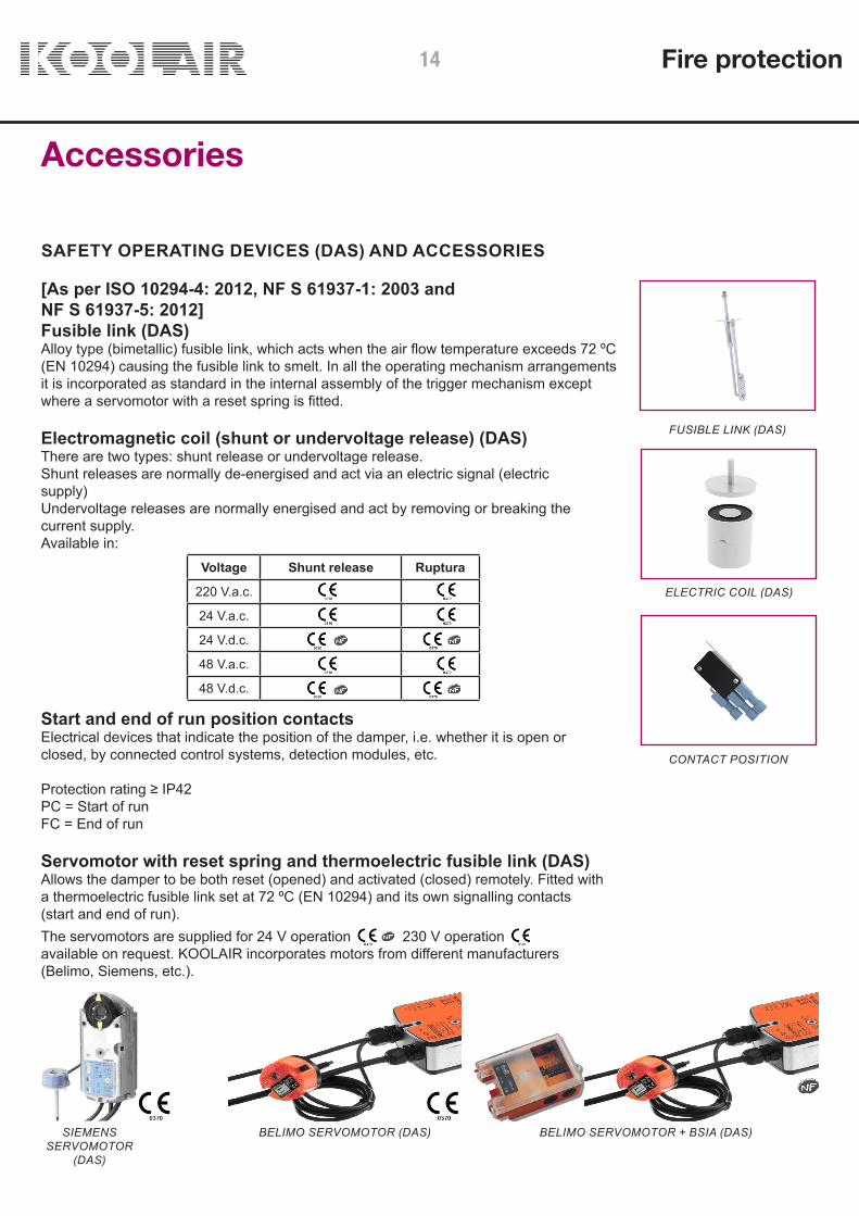
[As per ISO 10294-4: 2012, NF S 61937-1: 2003 and NF S 61937-5: 2012]Fusible link (DAS)Alloy type (bimetallic) fusible link, which acts when the air flow temperature exceeds 72 ºC(EN 10294) causing the fusible link to smelt. In all the operating mechanism arrangementsit is incorporated as standard in the internal assembly of the trigger mechanism exceptwhere a servomotor with a reset spring is fitted.
Electromagnetic coil (shunt or undervoltage release) (DAS)There are two types: shunt release or undervoltage release.Shunt releases are normally de-energised and act via an electric signal (electricsupply)Undervoltage releases are normally energised and act by removing or breaking thecurrent supply.Available in:
FUSIBLE LINK (DAS)
ELECTRIC COIL (DAS)
CONTACT POSITION
SIEMENSSERVOMOTOR
(DAS)
SAFETY OPERATING DEVICES (DAS) AND ACCESSORIES
Start and end of run position contactsElectrical devices that indicate the position of the damper, i.e. whether it is open orclosed, by connected control systems, detection modules, etc.
Protection rating ≥ IP42PC = Start of runFC = End of run
Servomotor with reset spring and thermoelectric fusible link (DAS)Allows the damper to be both reset (opened) and activated (closed) remotely. Fitted witha thermoelectric fusible link set at 72 ºC (EN 10294) and its own signalling contacts(start and end of run).The servomotors are supplied for 24 V operation
230 V operation
available on request. KOOLAIR incorporates motors from different manufacturers(Belimo, Siemens, etc.).
BELIMO SERVOMOTOR (DAS) BELIMO SERVOMOTOR + BSIA (DAS)
Voltage Shunt release Ruptura
220 V.a.c.
24 V.a.c.
24 V.d.c.
48 V.a.c.
48 V.d.c.
Fire protection14

C
C
D
AA
(L +
B) X
(H +
B
217
150150
A B C D
SCFR-PD 35 70 150 190
SCFR-GD 35 70 150 190
SFR3K1GT 50 100 180 175
SCFC-PD, SCFC-GDSCFR-PD, SCFR-GD, SFR3K1-GT15
0
150
217
150
(L + 100) x (H + 70)
150
190
35 35
E
SCFC-PD 65
SCFC-GD 70
Installation
Fire dampers are part of a building’s fire safety system and therefore special care must be taken with theirinstallation.
To install the dampers a perforation in the wall that is 100 mm greater than the nominal dimensions of the damper isrequired. No additional space is required for the mechanism box as it sits outside the wall or partition. As such, whenthe fire damper blade is in the closed position, it will be exactly vertical in the firewall, as if it were an extension of thiswall, as required by UNE-EN 1366-2.
Likewise, the dimensions indicated on the drawings must be respected in order to allow fitting of the operatingmechanism box. It is important not to force the damper blade open or closed by hand; activation must be via themechanism, whether mechanical or electric.
Positioning in wall
H n
omin
al +
B
L nominal + B
Mortar infill
L nominal = damper lengthH nominal = damper height
Ø nominal = Ø damper
Ø nominal + E
Mortar infill
Ø n
omin
al +
E
Positioning in slab
Ø nominal + 70
Mortar infill
Ø nominal + 70
Mortar infill
L Nominal + 70
H No
min
al +
70
SCFR-PD, SCFR-GD, SFR3K1GT SCFC-PD, SCFC-GD
Fire protection 15

100100
400400
200
200
97
200
100
150
Installation
Mounting in stud wall
SCFR-PD SCFC-PDWall studs must be offset
Test conditions: - 15-8577-939 (SCFC-PD): KNAUF “cortafuego DF” fireboard. - 15-8577-1076 (SCFR-PD): KNAUF “cortafuego DF” fireboard.
Wall studs must be offset
L nominal + 70
Ø nominal + 150
L nominal + 400
H nom
inal + 70
Ø nom
inal + 150
(Ø n
omin
al/2
) + 7
5
(Ø n
omin
al/2
) + 1
50
Ø nominal + 150
Ø nominal + 300
Ø nominaL
Ø n
omin
al
Ø n
omin
al
Ø nominal + 150
(Ø n
omin
al/2
) + 1
03
H nom
inal + 400
48 mmchannelsand uprightsin 400 mmspacing
48 mmchannelsand uprightsin 400 mmspacing
Pladur FOC 12.5 Pladur FOC 12.5
Pladur FOC 12.5
Pladur FOC 12.5 TYPE APladur FOC 12.5
TYPE B
Type A
Type A
Type B
Type B
Type A
Pladur FOC 12.5
NOTE: The distance betweenscrews should not exceed 150 mm
NOTE: The distancebetween screws should not exceed 150 mm
Pladur FOC 12.5
Screw PL 3.5x25 Screw PL 3.5x25Screw PL 3.5x35 Screw PL 3.5x35
Screw PL 3.5x35
Screw PL 3.5x35
Screw PL 3.5x35
Rock wool40 mm of 100 Kg/m3
Rock wool40 mm of 100 Kg/m3
To guarantee the correct fire damper operation, it is essential to read and follow the recommendations in theinstallation and operation manual. In addition, the installation must comply with all current national standards.
Fire protection16
200
75
75200
200
200
Installation
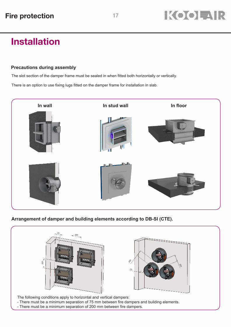
Precautions during assembly
In wall In floorIn stud wall
Arrangement of damper and building elements according to DB-SI (CTE).
The following conditions apply to horizontal and vertical dampers:- There must be a minimum separation of 75 mm between fire dampers and building elements.- There must be a minimum separation of 200 mm between fire dampers.
The slot section of the damper frame must be sealed in when fitted both horizontally or vertically.
There is an option to use fixing lugs fitted on the damper frame for installation in slab.
Fire protection 17
Installation
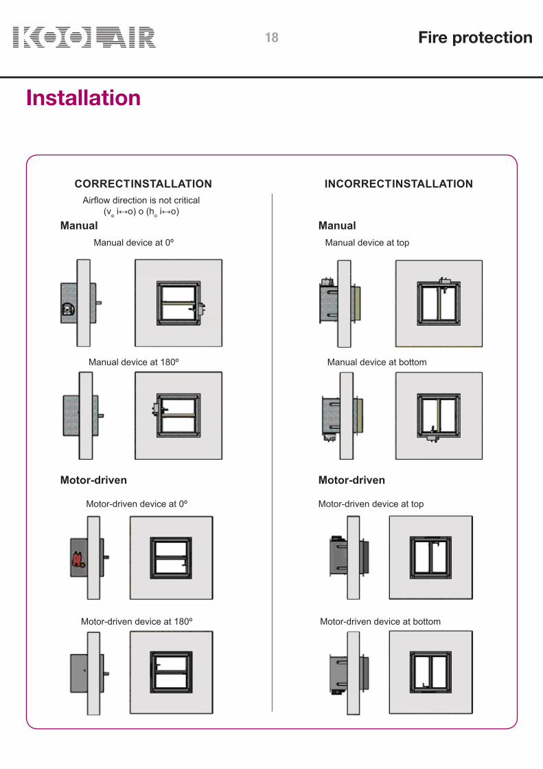
CORRECT INSTALLATION INCORRECT INSTALLATION
Manual ManualManual device at 0º
Airflow direction is not critical(ve i↔o) o (ho i↔o)
Manual device at top
Manual device at 180º Manual device at bottom
Motor-driven Motor-driven
Motor-driven device at 0º Motor-driven device at top
Motor-driven device at 180º Motor-driven device at bottom
Fire protection18

Installation
CORRECT INSTALLATION INCORRECT INSTALLATION
Manual ManualManual device at 0º Manual device at top
Manual device at 180º Manual device at bottom
Motor-driven Motor-driven
Moto-driven device at 0º Motor-driven device at top
Motor-driven device at 180º Motor-driven device at bottom
Airflow direction is not critical(ve i↔o) o (ho i↔o)
Fire protection 19

Operating mechanisms
Operating mechanisms and electrical connectionsOPERATION BY MEANS OF TH-70 BIMETALIC FUSE
(MANUAL RESET)OPERATION BY MEANS OF TH-70 BIMETALIC FUSE
+ COIL (MANUAL RESET)
- Damper is closed (operated) by providing electricsupply if coil “D” is an shunt release or by switching offsupply if coil “D” is an undervoltage release, or whenalloy fuse is triggered by temperatures over 72 °C-The damper is reset (opened) by pressing the “E” shaftuntil the electromagnet is energised (undervoltagerelease) or de-energised (shunt release) and insertingkey “B” in housing “C” and turning clockwise.
- Closing (operating) of the damper when button “A” is`pressed or alloy fuse is triggeredby a temperature over 72 °C.- The damper is reset (opened) manually by inserting key “B” in housing “C” and turning clockwise.
end (FC) and/or start of run (PC) switch end (FC) and/or start of run (PC) switch
COIL
Fire protection20

Operating mechanism
Operating mechanisms and electrical connectionsOPERATION BY BIMETALLIC FUSE TH-70 + COIL +
RESET MOTOR (AUTOMATIC RESET)SERVOMOTOR WITH RETURN SPRING
(AUTOMATIC RESET)
- Damper is closed (activated) by removing the powersupply (24 V or 230 V) to the servomotor with returnspring (“A” or “D”) or by switching off power by means ofa thermoelectric fusible link “B” when the temperatureexceeds 72° C inside or outside the damper.-Damper is reset (opened) by providing electric supply(24 V or 230 V) to servomotor with return spring (“A” or“D”).Manually inserting the lever in hole “A” and turningclockwise.
- Damper is closed (operated) by providing electricsupply to shunt release or by switching off supply toundervoltage release, or when alloy fuse is triggered bytemperatures over 72 °CSee p. 11 types of electrical power available in coils.-Damper is reset (opened) by providing electric supply toservomotor BL24-48 (24…48 V AC/DC) or BL110-230(110 …230 V AC) until fully opened.
end (FC) and/or start of run (PC) switch
COIL
MOTOR
end (FC) and/or start of run (PC) switch
end and start of run switchesintegrated in servomotor
Fire protection
Connection box 1
Connection box 1 Connection box 2
Connection box 2
Connection box
{MOTOR
Connection box
21
Activation
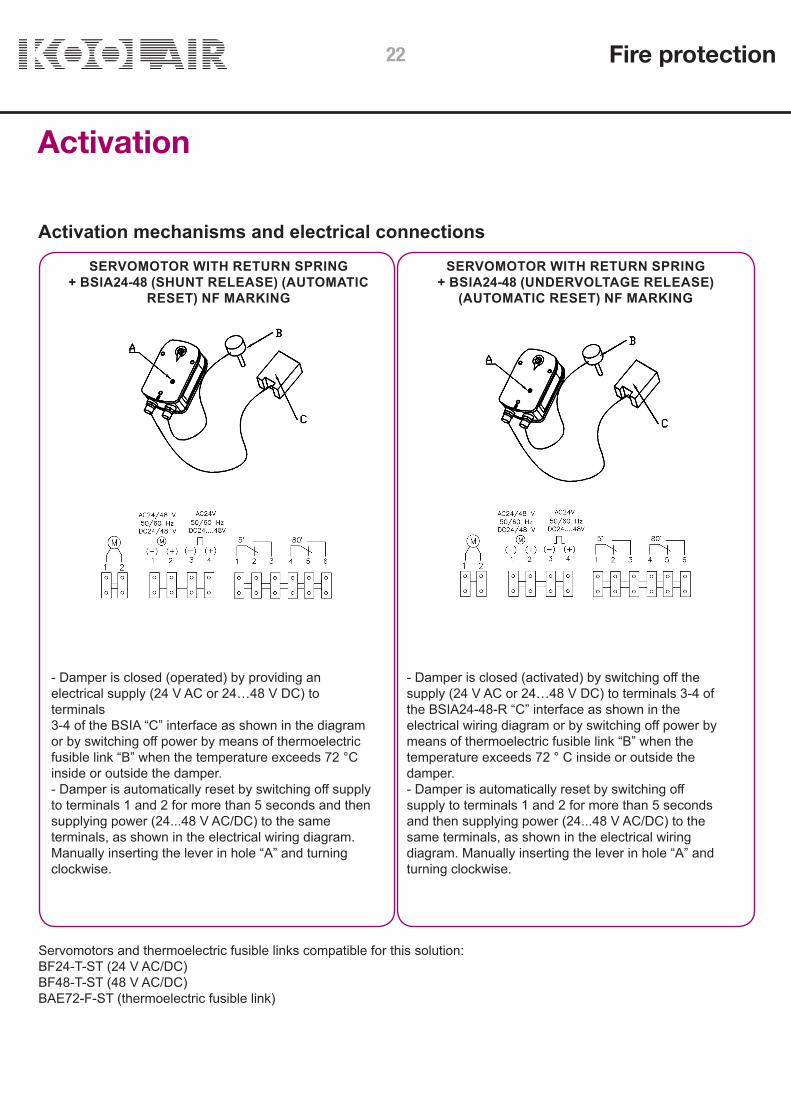
Activation mechanisms and electrical connectionsSERVOMOTOR WITH RETURN SPRING
+ BSIA24-48 (SHUNT RELEASE) (AUTOMATICRESET) NF MARKING
SERVOMOTOR WITH RETURN SPRING+ BSIA24-48 (UNDERVOLTAGE RELEASE)
(AUTOMATIC RESET) NF MARKING
- Damper is closed (activated) by switching off thesupply (24 V AC or 24…48 V DC) to terminals 3-4 ofthe BSIA24-48-R “C” interface as shown in theelectrical wiring diagram or by switching off power bymeans of thermoelectric fusible link “B” when thetemperature exceeds 72 ° C inside or outside thedamper.- Damper is automatically reset by switching offsupply to terminals 1 and 2 for more than 5 secondsand then supplying power (24...48 V AC/DC) to thesame terminals, as shown in the electrical wiringdiagram. Manually inserting the lever in hole “A” andturning clockwise.
- Damper is closed (operated) by providing anelectrical supply (24 V AC or 24…48 V DC) toterminals3-4 of the BSIA “C” interface as shown in the diagramor by switching off power by means of thermoelectricfusible link “B” when the temperature exceeds 72 °Cinside or outside the damper.- Damper is automatically reset by switching off supplyto terminals 1 and 2 for more than 5 seconds and thensupplying power (24...48 V AC/DC) to the sameterminals, as shown in the electrical wiring diagram.Manually inserting the lever in hole “A” and turningclockwise.
Servomotors and thermoelectric fusible links compatible for this solution:BF24-T-ST (24 V AC/DC)BF48-T-ST (48 V AC/DC)BAE72-F-ST (thermoelectric fusible link)
Fire protection22

50
50
50
ØD - 2
50 50400
H +
60
L + 60
H +
60
L + 60
400129 259
ØD
- 2
Special finishes with duct connection spigotsand truncated conical transformations
Reducers
Subject to checking with the Commercial Department, it is possible to supply rectangular and circular dampers withtransformation spigots on request as a non-standard finish.
These couplings may require a longer frame length than the defined standard in order to avoid the opening/closing ofthe blade from interfering with the spigot connections.
Length of the frame assembly in relation to the height of the damper.
Rectangular Circular Oval
If H < 250 If H ≥ 300
Fire protection 23

H \ L 200 250 300 350 400 450 500 550 600 650 700 750 800
1000,015 0,019 0,023 0,026 0,030 0,034 0,038 0,041 0,045 0,049 0,053 0,056 0,060 AL (m2)0,53 0,50 0,47 0,45 0,42 0,39 0,37 0,35 0,32 0,30 0,28 0,26 0,25 kp
-8 -7 -7 -7 -6 -6 -6 -6 -5 -5 -5 -5 -5 kdB(A)
1500,025 0,031 0,038 0,044 0,050 0,056 0,063 0,069 0,075 0,081 0,088 0,094 0,100 AL (m2)0,45 0,41 0,37 0,33 0,30 0,26 0,23 0,21 0,19 0,17 0,15 0,14 0,13 kp
-7 -6 -6 -6 -5 -5 -5 -5 -4 -4 -4 -4 -4 kdB(A)
2000,035 0,044 0,053 0,061 0,070 0,079 0,088 0,096 0,105 0,114 0,123 0,131 0,140 AL (m2)0,39 0,33 0,28 0,24 0,20 0,17 0,15 0,14 0,14 0,14 0,14 0,14 0,14 kp
-6 -6 -5 -5 -4 -4 -4 -4 -4 -3 -3 -3 -3 kdB(A)
2500,045 0,056 0,068 0,079 0,090 0,101 0,113 0,124 0,135 0,146 0,158 0,169 0,180 AL (m2)0,32 0,26 0,21 0,17 0,14 0,14 0,14 0,14 0,14 0,14 0,14 0,14 0,14 kp
-5 -5 -5 -4 -4 -4 -3 -3 -3 -3 -3 -3 -2 kdB(A)
3000,055 0,069 0,083 0,096 0,110 0,124 0,138 0,151 0,165 0,179 0,193 0,206 0,220 AL (m2)0,27 0,21 0,16 0,14 0,14 0,14 0,14 0,14 0,14 0,14 0,14 0,14 0,14 kp
-5 -5 -4 -4 -4 -3 -3 -3 -3 -2 -2 -2 -2 kdB(A)
3500,065 0,081 0,098 0,114 0,130 0,146 0,163 0,179 0,195 0,211 0,228 0,244 0,260 AL (m2)0,22 0,17 0,14 0,14 0,14 0,14 0,14 0,14 0,14 0,14 0,14 0,14 0,14 kp
-5 -4 -4 -3 -3 -3 -3 -2 -2 -2 -2 -2 -2 kdB(A)
4000,075 0,094 0,113 0,131 0,150 0,169 0,188 0,206 0,225 0,244 0,263 0,281 0,300 AL (m2)0,19 0,14 0,14 0,14 0,14 0,14 0,14 0,14 0,14 0,14 0,14 0,14 0,14 kp
-4 -4 -3 -3 -3 -3 -2 -2 -2 -2 -2 -1 -1 kdB(A)
4500,085 0,106 0,128 0,149 0,170 0,191 0,213 0,234 0,255 0,276 0,298 0,319 0,340 AL (m2)0,16 0,14 0,14 0,14 0,14 0,14 0,14 0,14 0,14 0,14 0,14 0,14 0,14 kp
-4 -4 -3 -3 -3 -2 -2 -2 -2 -1 -1 -1 -1 kdB(A)
5000,095 0,119 0,143 0,166 0,190 0,214 0,238 0,261 0,285 0,309 0,333 0,356 0,380 AL (m2)0,14 0,14 0,14 0,14 0,14 0,14 0,14 0,14 0,14 0,14 0,14 0,14 0,14 kp
-4 -3 -3 -3 -2 -2 -2 -2 -1 -1 -1 -1 -1 kdB(A)
5500,105 0,131 0,158 0,184 0,210 0,236 0,263 0,289 0,315 0,341 0,368 0,394 0,420 AL (m2)0,14 0,14 0,14 0,14 0,14 0,14 0,14 0,14 0,14 0,14 0,14 0,14 0,14 kp
-4 -3 -3 -2 -2 -2 -2 -1 -1 -1 -1 -1 -1 kdB(A)
6000,115 0,144 0,173 0,201 0,230 0,259 0,288 0,316 0,345 0,374 0,403 0,431 0,460 AL (m2)0,14 0,14 0,14 0,14 0,14 0,14 0,14 0,14 0,14 0,14 0,14 0,14 0,14 kp
-3 -3 -3 -2 -2 -2 -1 -1 -1 -1 -1 -1 0 kdB(A)
Technical data
SCFR-PD Table
Key:L width in mmH height in mmAL free area in m2
veff effective velocity in relation to the free surface in m/sΔP pressure loss in PaLwA sound level in dB(A)kp pressure loss correction factorkdB(A) sound-level correction factor
To determine the technical parameters of the dampers we must apply the following expressions (see example):ΔP = ΔPdiagram depending on the kp indicated in the above tableLwA = LwA diagram + kdB(A) indicated in the above table
Correction factors:kp pressure loss factorkdB(A) sound correction factorLwA - dB(A)damper = dB(A)diagram + kdB(A)
Fire protection24

0,45
0,30
0,15
30
25
40
45
50
35
1
10
100
1 10
∆P
(Pa)
Veff (m/s)
kp
LwA [dB(A)]
2 3 4 5 6 7 8 9
150
400
500
1000
750
4500
1500
2000
3000
0,01
0,10
1,00
1 10
A L(m
2 )
Veff (m/s)
Q (m
3 /h)
Technical data
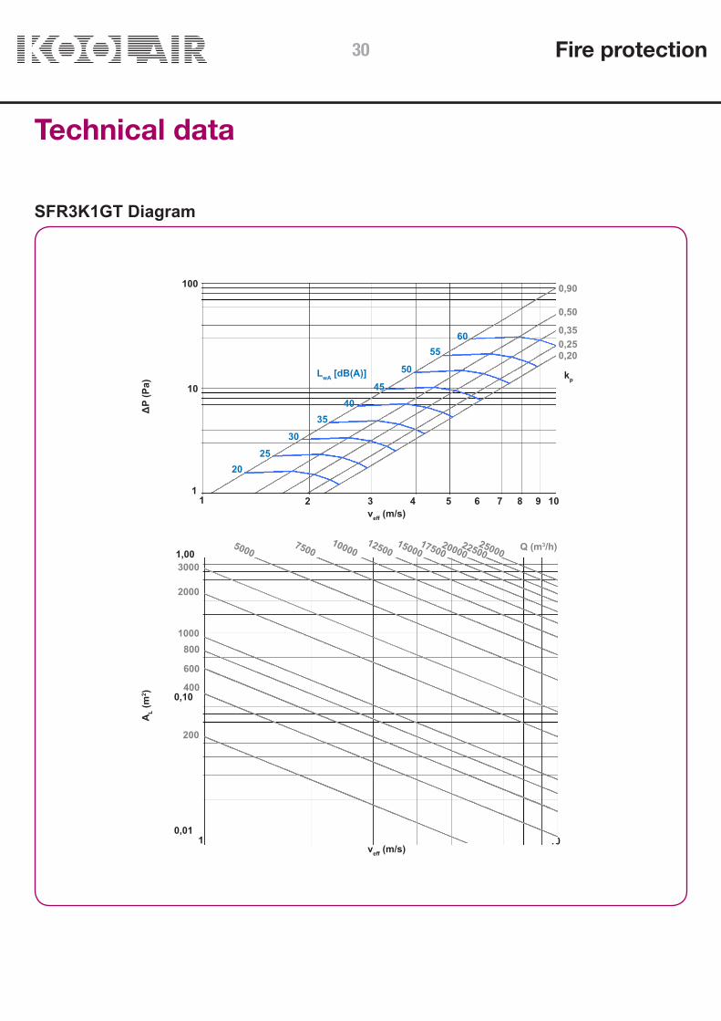
SCFR-PD Diagram
Selection example:For the given duct dimensions, we select a 600 x 500 mm SCFR-PD damper.We use the table on the previous page to find the following data:
AL = 0,285 m2 kp = 0,14 kdB(A)= -1
The technical data to achieve a flow rate of 5450 m3/h is required. Referring to the diagram above using the this flow rate and an area of 0,285 m2, we find a Veff of 5,5 m/s. With this speed and taking into account the value of kp we are given:Differential pressure: 4 PaNoise level: 41 dB(A)Applying LwA- dB(A) = 41 + (-1) = 40 dB(A)
Fire protection 25

H \ L 200 250 300 350 400 450 500 550 600 650 700 750 800
6500,120 0,150 0,180 0,210 0,240 0,270 0,300 0,330 0,360 0,390 0,420 0,450 0,480 AL (m2)0,84 0,75 0,69 0,63 0,58 0,53 0,49 0,45 0,42 0,39 0,36 0,34 0,31 kp
-3 -3 -2 -2 -2 -2 -1 -1 -1 -1 -1 0 0 kdB(A)
7000,130 0,163 0,195 0,228 0,260 0,293 0,325 0,358 0,390 0,423 0,455 0,488 0,520 AL (m2)0,81 0,67 0,60 0,54 0,49 0,44 0,40 0,37 0,34 0,30 0,28 0,25 0,23 kp
-3 -3 -2 -2 -2 -1 -1 -1 -1 -1 0 0 0 kdB(A)
7500,140 0,175 0,210 0,245 0,280 0,315 0,350 0,385 0,420 0,455 0,490 0,525 0,560 AL (m2)0,78 0,70 0,63 0,57 0,52 0,47 0,43 0,39 0,36 0,33 0,30 0,28 0,25 kp
-3 -2 -2 -2 -1 -1 -1 -1 -1 0 0 0 0 kdB(A)
8000,150 0,188 0,225 0,263 0,300 0,338 0,375 0,413 0,450 0,488 0,525 0,563 0,600 AL (m2)0,75 0,67 0,60 0,54 0,49 0,44 0,40 0,37 0,34 0,30 0,28 0,25 0,23 kp
-3 -2 -2 -2 -1 -1 -1 -1 0 0 0 0 0 kdB(A)
Technical data
SCFR-GD Table
Key:L width in mmH height in mmAL free area in m2
veff effective velocity in relation to the free surface in m/sΔP pressure loss in PaLwA sound level in dB(A)kp pressure loss correction factorkdB(A) sound-level correction factor
To determine the technical parameters of the dampers we must apply the following expressions (see example):ΔP = ΔPdiagram depending on the kp indicated in the above tableLwA = LwA diagram + kdB(A) indicated in the above table
Correction factors:kp pressure loss factorkdB(A) sound correction factorLwA - dB(A)damper = dB(A)diagram + kdB(A)
Fire protection26
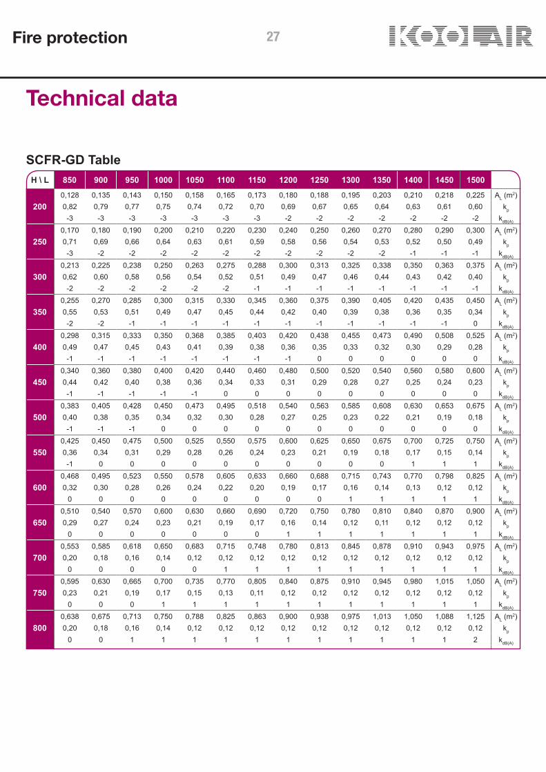
H \ L 850 900 950 1000 1050 1100 1150 1200 1250 1300 1350 1400 1450 1500
2000,128 0,135 0,143 0,150 0,158 0,165 0,173 0,180 0,188 0,195 0,203 0,210 0,218 0,225 AL (m2)0,82 0,79 0,77 0,75 0,74 0,72 0,70 0,69 0,67 0,65 0,64 0,63 0,61 0,60 kp
-3 -3 -3 -3 -3 -3 -3 -2 -2 -2 -2 -2 -2 -2 kdB(A)
2500,170 0,180 0,190 0,200 0,210 0,220 0,230 0,240 0,250 0,260 0,270 0,280 0,290 0,300 AL (m2)0,71 0,69 0,66 0,64 0,63 0,61 0,59 0,58 0,56 0,54 0,53 0,52 0,50 0,49 kp
-3 -2 -2 -2 -2 -2 -2 -2 -2 -2 -2 -1 -1 -1 kdB(A)
3000,213 0,225 0,238 0,250 0,263 0,275 0,288 0,300 0,313 0,325 0,338 0,350 0,363 0,375 AL (m2)0,62 0,60 0,58 0,56 0,54 0,52 0,51 0,49 0,47 0,46 0,44 0,43 0,42 0,40 kp
-2 -2 -2 -2 -2 -2 -1 -1 -1 -1 -1 -1 -1 -1 kdB(A)
3500,255 0,270 0,285 0,300 0,315 0,330 0,345 0,360 0,375 0,390 0,405 0,420 0,435 0,450 AL (m2)0,55 0,53 0,51 0,49 0,47 0,45 0,44 0,42 0,40 0,39 0,38 0,36 0,35 0,34 kp
-2 -2 -1 -1 -1 -1 -1 -1 -1 -1 -1 -1 -1 0 kdB(A)
4000,298 0,315 0,333 0,350 0,368 0,385 0,403 0,420 0,438 0,455 0,473 0,490 0,508 0,525 AL (m2)0,49 0,47 0,45 0,43 0,41 0,39 0,38 0,36 0,35 0,33 0,32 0,30 0,29 0,28 kp
-1 -1 -1 -1 -1 -1 -1 -1 0 0 0 0 0 0 kdB(A)
4500,340 0,360 0,380 0,400 0,420 0,440 0,460 0,480 0,500 0,520 0,540 0,560 0,580 0,600 AL (m2)0,44 0,42 0,40 0,38 0,36 0,34 0,33 0,31 0,29 0,28 0,27 0,25 0,24 0,23 kp
-1 -1 -1 -1 -1 0 0 0 0 0 0 0 0 0 kdB(A)
5000,383 0,405 0,428 0,450 0,473 0,495 0,518 0,540 0,563 0,585 0,608 0,630 0,653 0,675 AL (m2)0,40 0,38 0,35 0,34 0,32 0,30 0,28 0,27 0,25 0,23 0,22 0,21 0,19 0,18 kp
-1 -1 -1 0 0 0 0 0 0 0 0 0 0 0 kdB(A)
5500,425 0,450 0,475 0,500 0,525 0,550 0,575 0,600 0,625 0,650 0,675 0,700 0,725 0,750 AL (m2)0,36 0,34 0,31 0,29 0,28 0,26 0,24 0,23 0,21 0,19 0,18 0,17 0,15 0,14 kp
-1 0 0 0 0 0 0 0 0 0 0 1 1 1 kdB(A)
6000,468 0,495 0,523 0,550 0,578 0,605 0,633 0,660 0,688 0,715 0,743 0,770 0,798 0,825 AL (m2)0,32 0,30 0,28 0,26 0,24 0,22 0,20 0,19 0,17 0,16 0,14 0,13 0,12 0,12 kp
0 0 0 0 0 0 0 0 0 1 1 1 1 1 kdB(A)
6500,510 0,540 0,570 0,600 0,630 0,660 0,690 0,720 0,750 0,780 0,810 0,840 0,870 0,900 AL (m2)0,29 0,27 0,24 0,23 0,21 0,19 0,17 0,16 0,14 0,12 0,11 0,12 0,12 0,12 kp
0 0 0 0 0 0 0 1 1 1 1 1 1 1 kdB(A)
7000,553 0,585 0,618 0,650 0,683 0,715 0,748 0,780 0,813 0,845 0,878 0,910 0,943 0,975 AL (m2)0,20 0,18 0,16 0,14 0,12 0,12 0,12 0,12 0,12 0,12 0,12 0,12 0,12 0,12 kp
0 0 0 0 0 1 1 1 1 1 1 1 1 1 kdB(A)
7500,595 0,630 0,665 0,700 0,735 0,770 0,805 0,840 0,875 0,910 0,945 0,980 1,015 1,050 AL (m2)0,23 0,21 0,19 0,17 0,15 0,13 0,11 0,12 0,12 0,12 0,12 0,12 0,12 0,12 kp
0 0 0 1 1 1 1 1 1 1 1 1 1 1 kdB(A)
8000,638 0,675 0,713 0,750 0,788 0,825 0,863 0,900 0,938 0,975 1,013 1,050 1,088 1,125 AL (m2)0,20 0,18 0,16 0,14 0,12 0,12 0,12 0,12 0,12 0,12 0,12 0,12 0,12 0,12 kp
0 0 1 1 1 1 1 1 1 1 1 1 1 2 kdB(A)
Technical data
SCFR-GD Table
Fire protection 27

0,84
0,60
0,12
30
25
40
45
50
35
0,36
1
10
100
1 10
∆P
(Pa)
Veff (m/s)
kp
LwA [dB(A)]
2 3 4 5 6 7 8 9
400 500
750
1000
1500
750
2000 30000,10
1,00
1 10
A L(m
2 )
Veff (m/s)
Q (m
3 /h)
Technical data
SCFR-GD Diagram
Selection example:For the given duct dimensions, we select a 1000 x 300 mm SCFR-GD damper.We use the table on the previous page to find the following data:
AL = 0,25 m2 kp = 0,56 kdB(A)= -2
The technical data to achieve a flow rate of 5500 m3/h is required. Referring to the diagram above using the this flow rate and an area of 0,25 m2, we find a Veff of 6 m/s. With this speed and taking into account the value of kp we are given:Differential pressure: 20 PaNoise level: 44 dB(A)Applying LwA- dB(A) = 44 - 2 = 42 dB(A)
Fire protection28

L \ H 200 250 300 350 400 450 500 550 600 650 700 750 800
2000,024 0,033 0,042 0,051 0,060 0,068 0,077 0,086 0,095 0,104 0,112 0,121 0,130 AL (m2)0,84 0,75 0,68 0,64 0,60 0,57 0,54 0,52 0,50 0,49 0,47 0,46 0,45 kp
-27 -24 -21 -19 -17 -16 -14 -13 -12 -11 -10 -9 -9 kdB(A)
3000,038 0,052 0,066 0,079 0,093 0,107 0,121 0,135 0,148 0,162 0,176 0,190 0,204 AL (m2)0,71 0,63 0,58 0,54 0,51 0,48 0,46 0,44 0,43 0,41 0,40 0,39 0,38 kp
-22 -19 -16 -14 -12 -11 -9 -8 -7 -6 -5 -5 -4 kdB(A)
4000,052 0,070 0,089 0,108 0,127 0,146 0,164 0,183 0,202 0,221 0,240 0,258 0,277 AL (m2)0,63 0,56 0,52 0,48 0,45 0,43 0,41 0,39 0,38 0,37 0,36 0,35 0,34 kp
-19 -15 -13 -11 -9 -7 -6 -5 -4 -3 -2 -1 0 kdB(A)
5000,065 0,089 0,113 0,137 0,160 0,184 0,208 0,232 0,256 0,279 0,303 0,327 0,351 AL (m2)0,58 0,52 0,47 0,44 0,41 0,39 0,38 0,36 0,35 0,34 0,33 0,32 0,31 kp
-16 -13 -10 -8 -6 -5 -4 -2 -1 0 1 1 2 kdB(A)
6000,079 0,108 0,136 0,165 0,194 0,223 0,252 0,280 0,309 0,338 0,367 0,396 0,424 AL (m2)0,54 0,48 0,44 0,41 0,39 0,37 0,35 0,34 0,32 0,31 0,30 0,30 0,29 kp
-14 -11 -8 -6 -4 -3 -1 0 1 2 3 4 4 kdB(A)
7000,092 0,126 0,160 0,194 0,228 0,261 0,295 0,329 0,363 0,397 0,430 0,464 0,498 AL (m2)0,51 0,45 0,41 0,39 0,36 0,34 0,33 0,32 0,30 0,29 0,29 0,28 0,27 kp
-12 -9 -6 -4 -3 -2 -1 1 2 3 3 4 5 kdB(A)
8000,106 0,145 0,184 0,222 0,261 0,300 0,339 0,378 0,416 0,455 0,494 0,533 0,572 AL (m2)0,48 0,43 0,39 0,37 0,34 0,33 0,31 0,30 0,29 0,28 0,27 0,26 0,26 kp
-11 -7 -5 -3 -1 0 0 1 2 3 4 5 6 kdB(A)
9000,120 0,163 0,207 0,251 0,295 0,339 0,382 0,426 0,470 0,514 0,558 0,601 0,645 AL (m2)0,46 0,41 0,38 0,35 0,33 0,31 0,30 0,29 0,28 0,27 0,26 0,25 0,25 kp
-10 -6 -4 -1 0 1 1 1 2 3 4 5 6 kdB(A)
10000,133 0,182 0,231 0,280 0,328 0,377 0,426 0,475 0,524 0,572 0,621 0,670 0,719 AL (m2)0,44 0,39 0,36 0,34 0,32 0,30 0,29 0,28 0,27 0,26 0,25 0,24 0,24 kp
-8 -5 -2 0 2 2 2 3 4 5 6 6 7 kdB(A)
11000,147 0,201 0,254 0,308 0,362 0,416 0,470 0,523 0,577 0,631 0,685 0,739 0,792 AL (m2)0,43 0,38 0,35 0,32 0,31 0,29 0,28 0,27 0,26 0,25 0,24 0,23 0,23 kp
-7 -4 -1 1 3 3 3 2 3 4 5 5 6 kdB(A)
12000,160 0,219 0,278 0,337 0,396 0,454 0,513 0,572 0,631 0,690 0,748 0,807 0,866 AL (m2)0,41 0,37 0,34 0,31 0,30 0,28 0,27 0,26 0,25 0,24 0,23 0,23 0,22 kp
-6 -3 0 2 4 4 4 3 4 3 4 4 5 kdB(A)
13000,174 0,238 0,302 0,365 0,429 0,493 0,557 0,621 0,684 0,748 0,812 0,876 0,940 AL (m2)0,40 0,36 0,33 0,30 0,29 0,27 0,26 0,25 0,24 0,23 0,23 0,22 0,21 kp
-5 -2 1 3 4 5 5 4 5 4 0 1 2 kdB(A)
14000,188 0,256 0,325 0,394 0,463 0,532 0,600 0,669 0,738 0,807 0,876 0,944 1,013 AL (m2)0,39 0,35 0,32 0,30 0,28 0,26 0,25 0,24 0,23 0,23 0,22 0,21 0,21 kp
-5 -1 1 4 5 6 6 4 5 4 1 1 2 kdB(A)
15000,201 0,275 0,349 0,423 0,496 0,570 0,644 0,718 0,792 0,865 0,939 1,013 1,087 AL (m2)0,38 0,34 0,31 0,29 0,27 0,26 0,25 0,24 0,23 0,22 0,21 0,21 0,20 kp
-4 0 2 4 6 7 7 5 6 5 2 2 3 kdB(A)
Technical data
SFR3K1GT Table
Fire protection 29
1
10
100
1 2 3 4 5 6 7 8 9 10
2530
3540
45
50
0,250,35
0,50
0,90
veff (m/s)
kp
ΔP
(Pa)
50007500
1000012500
1500025000
3000
2000
1000800
600
400
200
1 10veff (m/s)
0,01
0,10
1,00
AL (
m2 )
Q (m3/h)
0,20
20
5560
LwA [dB(A)]
1750020000
22500
Technical data
SFR3K1GT Diagram
Fire protection30
100 125 160 200 250 315 355
1
10
100
10 100 1000 10000
∆P
[Pa]
Q [m 3/h]
30
35
40
45
50
55
LWA [dB(A)]
2
3
5
6
7
8
9
10 11 12
4
veff [m/s]
20
25
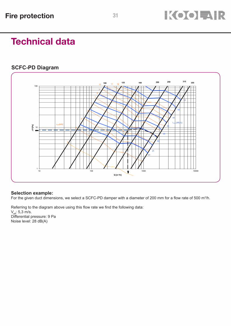
Technical data
Selection example:For the given duct dimensions, we select a SCFC-PD damper with a diameter of 200 mm for a flow rate of 500 m3/h.
Referring to the diagram above using this flow rate we find the following data:Veff: 5,3 m/s.Differential pressure: 9 PaNoise level: 28 dB(A)
SCFC-PD Diagram
Fire protection 31
400
450
500
560
630
650 700
1
10
100
1000 10000 100000
∆P
[Pa]
Q [m 3/h]
30
35
40
45
50
55
LWA [dB(A)]
2
3
5
6
7
8
910
11
12
4
veff [m/s]
20
25
710 750 800
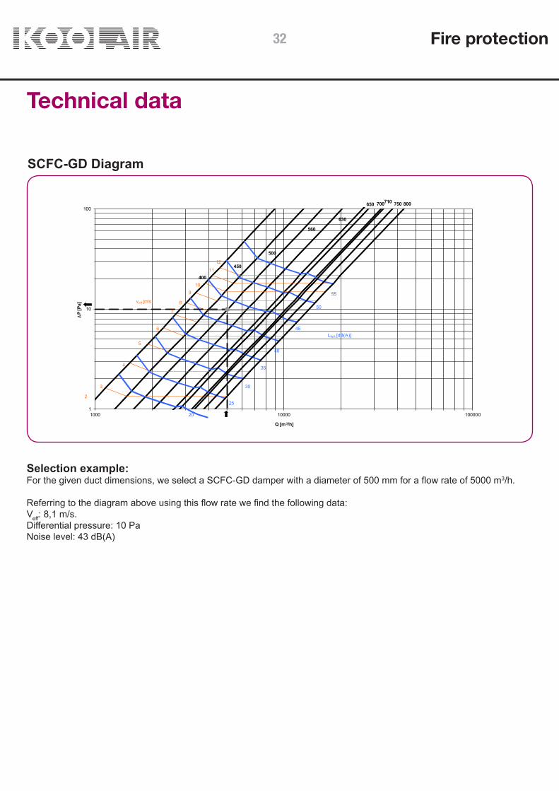
Technical data
Selection example:For the given duct dimensions, we select a SCFC-GD damper with a diameter of 500 mm for a flow rate of 5000 m3/h.
Referring to the diagram above using this flow rate we find the following data:Veff: 8,1 m/s.Differential pressure: 10 PaNoise level: 43 dB(A)
SCFC-GD Diagram
Fire protection32

Coding
Damper model (see table p. 5 declared performance)
SCFR-PD SCFR-GDSFR3K1GTSCFC-PDSCFC-GD
Activation. Components
+ TH-70+ TH-70 + FC + TH-70 + PC/FC + B IMP 24 V CC + FC+ B IMP 48 V CC + FC+ B IMP 24 V CA + FC+ B IMP 48 V CA + FC+ B IMP 220 V + FC+ B RUPT 24 V CC + FC+ B RUPT 48 V CC + FC+ B RUPT 24 V CA + FC+ B RUPT 48 V CA + FC+ B RUPT 220 V + FC+ MOTOR-24-T+ MOTOR-230-T+ B IMP 24 V CC + FC/PC + MOTOR-24/48-RESET+ B IMP 48 V CC + FC/PC + MOTOR-24/48-RESET + B IMP 24 V AC + FC/PC + MOTOR-24/48-RESET+ B IMP 48 V AC + FC/PC + MOTOR-24/48-RESET + B IMP 220 V AC + FC/PC + MOTOR-110/230-RESET
+ B RUPT 24 V CC + FC/PC + MOTOR-24-RESET+ B RUPT 48 V CC + FC/PC + MOTOR-24/48-RESET+ B RUPT 24 V AC + FC/PC + MOTOR-24/48-RESET+ B RUPT 48 V AC + FC/PC + MOTOR-24/48-RESET+ B RUPT 220 V AC + FC/PC + MOTOR-110/230-RESET+ MOTOR-24-T + BSIA24-48 (NF Marking)+ MOTOR-48-T + BSIA24-48 (NF Marking)+ MOTOR-24-T + BSIA-R-24-48 (NF Marking)+ MOTOR-48-T + BSIA-R-24-48 (NF Marking)
Accessories
without mounting lugswith lugs for slab floorwithout mounting lugs, with inspection panelswith lugs for slab floor, with inspection panels
Size
Length x heightDiameter
Fire protection 33
CONTENTS
Description 35Dimensions 36Installation 37 Technical Data 38
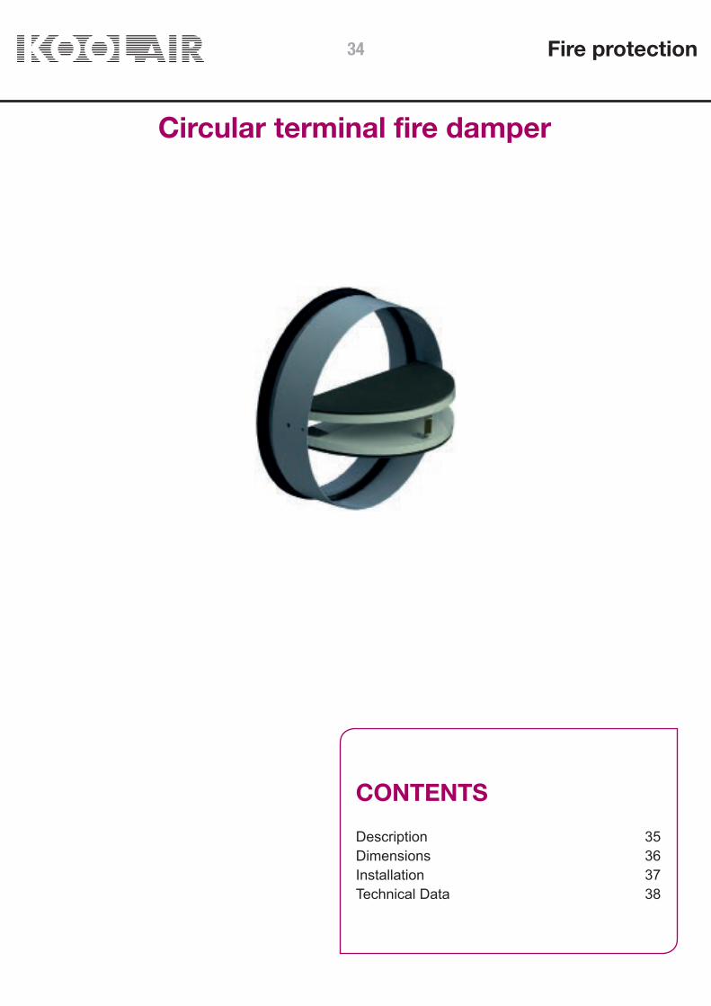
Circular terminal fire damper
Fire protection34

Circular terminal fire damper
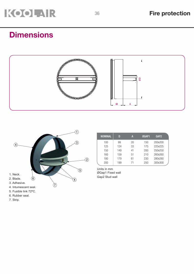
DescriptionKoolair’s BDK circular terminal fire dampers are approved withrespect to RPC305, according to EN 15650 and according to testingstandard UNE-EN 1366-2.They are installed in circular ventilation and air conditioning ductworkinstallations where the ductwork penetrates walls to prevent thepropagation of fire.
OperationThe BDK damper is held open by a fusible link. Whenthe temperature exceeds 72 °C the fuse smelts and the mechanismactivates automatically closing the damper blades. Two strips ensurethat the damper remains close
ModelosBDK-60: Circular terminal fire damper with 60 min fire integrity andinsulation and prevention of smoke leakage. EI 60 (ve i → o) S,according to EN 13501-3.
BDK-120: Circular terminal fire damper with 120 min integrity andinsulation and prevention of smoke leakage. EI 120 (ve i → o) S,according to EN 13501-3.
AccesoriosFC. End of run switch.GPD-Ø. Extract louvre and mounting frame.AM. Mounting ring.
Fire protection 35
60 A
Ø D
1
3
2
5
4
4
6
7
Dimensions
1. Neck.2. Blade.3. Adhesive.4. Intumescent seal.5. Fusible link 72ºC.6. Rubber seal.7. Strip.
Units in mmØGap1 Fixed wallGap2 Stud wall
NOMINAL D A ØGAP1 GAP2
100 99 20 150 200x200 125 124 33 175 225x225 150 149 41 200 250x250 160 159 51 210 260x260 180 179 61 230 280x280 200 199 71 250 300x300
Fire protection36

60
Ø n
+ 50
150
□(Ø
n+
50)
□(Ø
n+
200)
BDK damper installation with directconnection to GPD extract louvre
Stud wall Fixed wall
EXTRACT VALVE
DUCT
BDK DAMPER
3 SHEETS OFPLASTERBOARD
FRAME PLASTERBOARD
FIRE SIDE
ROCK WOOL
EXTRACT VALVE FRAME
MOUNTING RING
STUD WALL
EXTRACT VALVE
DUCT
BDK DAMPER
EXTRACT VALVE FRAME
MOUNTING RING
FIXED WALL
FIXED WALL
FIRE SIDE
min 100
The BDK circular terminal fire damper can be installed in a fixed wall or a stud wall with a direct connection to a GPDextract louvre.The characteristics of both types of installation are shown below.
Fire protection 37

80
Ø n
+ 50
80
□(Ø
n+ 5
0)
□(Ø
n+ 2
00)
BDK damper installation with ductworkconnection
Stud wall Fixed wall
COLLAR (Ø100 TO Ø200 MM)(MOUNTING RING)
COLLAR (Ø100 TO Ø200 MM)(MOUNTING RING)
DUCT (Ø100 TO Ø200 MM)DUCT (Ø100 TO Ø200 MM)
DUCT (Ø100 TO Ø200 MM) BDKDUCT(Ø100 TO Ø200 MM)
DAMPER
3 SHEETS OFPLASTERBOARD
FRAMEPLASTERBOARD
FIRE SIDE
ROCK WOOL
EXTRACT VALVE FRAME
STUDWALL
BDK DAMPER
FIXED WALL
FIXED WALL
MORTAR
FIRE SIDE
min 100min 100
The BDK circular terminal fire damper can be installed in a fixed wall or a stud wall with a ductwork connection.The characteristics of both types of installation are shown below.
Fire protection38

Q (m3/h) Lwa [dB(A)] ΔP (Pa) Vk (m/s)
100
88 30 17 3,1109 35 27 3,9136 40 41 4,8168 45 64 6,0
125
150 30 17 3,4186 35 26 4,2231 40 40 5,2287 45 61 6,5
150
231 30 16 3,6287 35 25 4,5357 40 38 5,6444 45 59 7,0
160
270 30 16 3,7335 35 24 4,6417 40 38 5,8518 45 58 7,2
180
357 30 15 3,9444 35 24 4,8552 40 37 6,0686 45 57 7,5
200
460 30 15 4,1571 35 23 5,1710 40 36 6,3882 45 56 7,8
125160
10
100
10 100 1000
Q [m3/h]
∆P
[Pa]
30
35
40
45
50
LWA [dB(A)]
3
5
6
78
9 10
4
veff [m/s]
25
Technical data
KEYQ (m3/h): Flow rate.∆P (Pa): Pressure loss.LwA [dB(A)]: Sound power level.Vk (m/s): Duct velocity.
TAMAÑO
Quick selection tables
Selection chart
Fire protection 39

CONTENTS
Description 41Dimensions 43
Intumescent air transfer grilles
Fire protection40

DescriptionKoolair LV intumescent grilles are used to compartmentalise zones inthe event of a fire or high temperature gases.
The LV grilles contain an intumescent material that expands in theevent of fire to seal the ventilation duct in accordance with BS 476:Part 20 and 22 and UNE-EN 1634-1:2000.
There are two models in the LV grille range, each with differentcharacteristics to allow the correct selection to be made depending onthe desired application.
The LVV40/LVC40 range with PVC coated sodium silicate grilles for walls, doors and both circular and rectangular ductwork.
The LVV40/LVC40 models provide 60 minutes of resistance in caseof fire or high temperature smoke (EI30/EI60) and the expansiontime for the intumescent material to seal the ventilation shaft isapproximately 5 minutes.
They are designed to facilitate without excessive noise and efficient airflow. They allow air to flow in both directions through the grille and can be mounted both vertically and horizontally depending on the application. They have a free area of approximately 60%.
They are designed to be easily installed, contain no moving partsand are maintenance free and resistant to clogging.
The grilles in the LVH44/LVHC44 range are high performance grilles,designed for use in aggressive work environments. They are made of graphite lined aluminum with protected edges of steel metallic structure and designed for applications in walls, doors, floors,ceilings and both circular and rectangular ventilation ductwork. Theyare suitable for outdoor use and can be mounted both vertically andhorizontally.
The LVH44/LVHC44 models provide 120 minutes of resistance incase of fire and high temperature smoke (EI90/EI120) and theexpansion time for the intumescent material to seal the ventilationshaft is approximately 2 minutes. They are designed without excessive noise and efficient airflow at normal and high air flow rates. They have a free area of approximately 60%.
They have a steel frame that protects the intumescent material fromany deformations that may occur in the grille housing structure.Likewise, in these models, the metal frame that protects theintumescent material prevents it from deteriorating as a result of hot,corrosive or high velocity air passing through.They contain no moving parts and are low maintenance andresistant to vibration damage.
Intumescent air transfer grilles
Fire protection 41

Intumescent air transfer grilles
Fire protection
ModelsUp to 60 minutes resistance to fire and high temperature gases.
LVV40. EI30/EI60 rectangular intumescent grille with straight blades, made with PVC coated sodium silicate. LVC40. EI30/EI60 circular intumescent grille with straight blades, made with PVC coated sodium silicate.
Up to 120 minutes resistance to fire and hot gases.
LVH44. EI90/EI120 rectangular intumescent grille with straight blades, made of graphite lined aluminum with protected edges of steel metallic structure. LVHC44. EI90/EI120 circular intumescent grille with straight blades, made of graphite lined aluminum with protected edges of steel metallic structure.
ApplicationsLVV40 / LVC40: walls, doors and both circular and rectangular ventilation ductwork.LVH44 / LVHC44: walls, doors, floors, ceilings and both circular and rectangular ventilation ductwork..
Summary of declared performance
Model Dimensions(mm) Construction Applications Classification
Length: 100 to 600 mm *Height: 100 to 600 mm *Thickness: 40 mm
Sodium Silicate and PVC EI30 / EI60
Sodium Silicate and PVC EI30 / EI60
EI90 / EI120
Graphite, aluminum and
steel
Graphite, aluminum and
steel
EI90 / EI120
Walls, doors andrectangular ventilationductwork.
Diameter: 100 to 600 mmThickness: 40 mm
Walls, doors andcircular ventilation ductwork.
Length: 100 to 600 mm *Height: 100 to 600 mm *Thickness: 44 mm
Walls, doors, floors,ceilings and rectangularventilation ductwork.
Ø: 100 to 600 mm (EI90)Ø: 100 and 150 mm (EI120)Thickness: 44mm
Walls, doors, floors,ceilings and circularventilation ductwork.
*in 25 mm increments
LVV40
LVC40
LVH44
LVHC44
42

Intumescent air transfer grilles
DimensionsLVV40: Length: 100 mm to 600 mm (in 25 mm increments)Height: 100 mm to 600 mm (in 25 mm increments)Thickness: 40 mm
LVC40:Diameter: up to 600 mmThickness: 40 mm
LVH44:Length: 100 mm to 600 mm (in 25 mm increments)Height: 100 mm to 600 mm (in 25 mm increments)Thickness: 44 mm
LVHC44:Diameter: up to 600 mm (EI90) and up to 150 mm (EI120)Thickness: 44 mm
L x
H
(L –
2) x
(H –
2)
1 2 3 4
H –
2
L – 2
44
Installation1. Opening2. Intumescent grille3. Seal between grille and wall4. External grille
Fire protection 43
SMLD Smoke Evacuation Damper
CONTENTS
Description 45Dimensions 47Installation 49Electrical connections 50Technical data 52Coding 54
Fire protection44

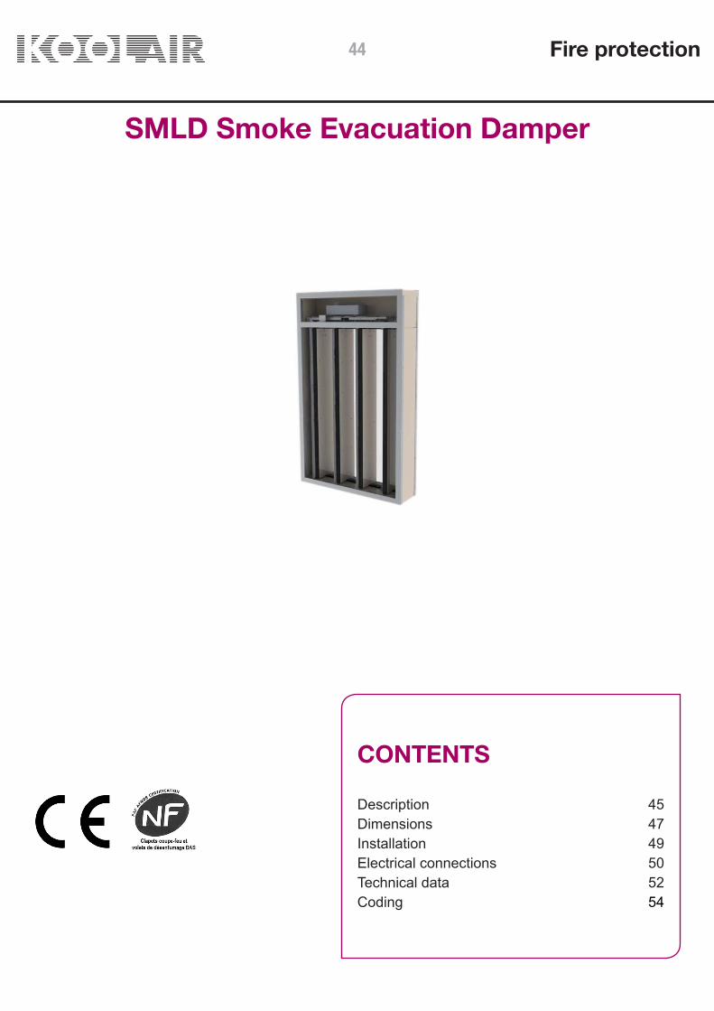
SMLD Smoke Evacuation Damper
DescriptionMulti-blade smoke damper, suitable for use in low profile ductwork,approved in accordance with test standard UNE EN 1366-10 andclassified according to EN 13501-4: EI 120 (ved i↔o) S 1500 AAmulti.
Designed according to EN 12101-8 specifications. Structuremade from refractory material with an external cover madefrom sheet steel and blades made from refractory material.Installed vertically within the wall, with a vertical smoke evacuationduct, with the option of a mounting assembly frame previously fixedto the duct.
Includes an RPK protective and decorative grille, specific for smokeevacuation and manufactured with anodised aluminium profiles,fitted to the front side of the damper, i.e. the side on display in thebuilding.
Can be used for smoke extraction and air intake (air flow in either direction).
OperationThe operating mechanism/s are incorporated in the upper part ofthe damper where they are protected from smoke and hightemperatures.
- Automatic operation (closing) and resetting (opening) by means ofa servomotor (CE Marking):
SMLD smoke extract dampers are operated and reset by means of aservomotor with a supply voltage of 24 V AC/DC (model BLE24) or230 V AC (model BLE230).These motors include start and end of stroke limit switches tomonitor the opening/closing status of the damper.
Other operating options:- Operation (opening) by means of electric coil with manual reset(closing) (CE and NF marking). Optional limit switch/es: 24V DC electric shunt release coil 48V DC electric shunt release coil 24V AC electric shunt release coil 48V AC electric shunt release coil
- Automatic reset by means of servomotor BL24-48, with a supplyvoltage of 24 ... 48 V AC/DC, operation by previously mentionedelectric coils. Limit switch/es can be optionally incorporated. (CE andNF Marking)
Fire protection 45

L: 2 → 4 lamasH: 200 → 1000
EI-120 (ved i↔o) S 1500 AA multi
(500 Pa)
SMLD Smoke Evacuation Damper
RegulationsThe SMLD damper is approved according to the European Test Standard UNE-EN 1366-10 and European classificationstandard UNE-EN 13501-4, where EI 120 (ved i↔o) S 1500 AA multi:
(E) Integrity(I) Isolation(120) : 120 minute resistance(ved) Installed vertically in duct(i ↔ o) Symmetric. Suitable for fire in both directions (interior-exterior and exterior-interior)(S) Airtightness. Leakage through the damper closing blades <200 m3/h*m2
(1500) Suitable for a working pressure range from 1500 Pa negative (extract) to 500 Pa positive (supply). (AA)Automatic intervention.(multi) Suitable for multi-compartment systems
The SMLD smoke damper can be associated with KOOLAIR’s KOOLCOM management and monitoring systemfor fire dampers.
To guarantee correct fire damper operation, it is essential to read and follow the recommendations in theinstallation and operation manual. In addition, the installation must comply with all current national standards.
Further information and updates, as well as the installation and operating manual, can be found on our website(www.koolair.com).
CE MarkingThe Koolair SMLD smoke evacuation damper, has CE marking, No. 0370-CPR-1688in compliance with RPC-305/2011/EU, according to EN15650:2010.
NF MarkingThe Koolair SMLD smoke evacuation damper, is certified to NF marking. (NF264 Certification Standard, NF S 61-937-10 smoke evacuation dampers).
Declared smoke extraction performance
Smokeextractduct
1366-8certified
vertical duct
SMLDCPR-1688
Installationlocation Installation ClassificationDimensions
(mm)
Fire protection46

SMLD Smoke Evacuation DamperDimensionsDamper Drawing
Fire resistance according to EN 13501 - 4EI 120 (Ved - i o) S 1500 AA MULTI
Dimensions and openings
Dimensions in mm
L Dimensions (see drawing)
Number of blades (N) Nominal dimensionsLn (mm)
External dimensions Lht (mm)
2 354 418
3 527 591
4 700 764
H Dimensions (see diagram)
Nominal dimensionsHn (mm)
De 200 a 1000 pasos de 50 en 50
Press to open the components’protective cover
Space for mechanism
Product label
Casing
Electricalconnections Frame
Blades
Fire protection 47

SMLD Smoke Evacuation DamperDimensionsInstallation and commissioning
RPK Smoke extract grille
SMLD Damper
Mounting frame
Holes Ø 3
SMLD damper application in installations which employ ductwork different from that which has been submitted forcertification testing: SMLD smoke control dampers, for use in multi-compartment systems (multi), are applicable in ductsthat are tested in accordance with EN1366-8 as appropriate for each particular case or manufactured from materials withthe same density or greater thickness than those used in the certification test. Ductwork must be installed in accordancewith the manufacturer’s latest drawings.
Fire protection48
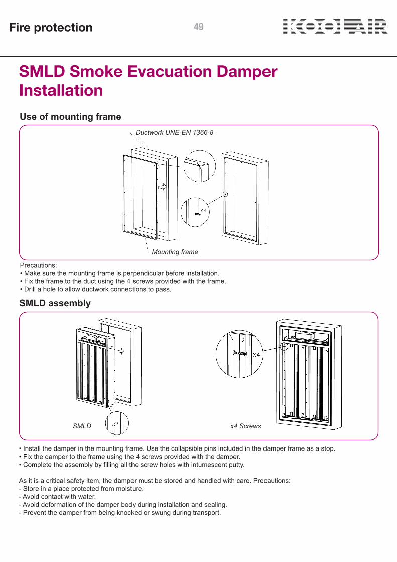
SMLD Smoke Evacuation DamperInstallationUse of mounting frame
Ductwork UNE-EN 1366-8
Mounting frame
Precautions:• Make sure the mounting frame is perpendicular before installation.• Fix the frame to the duct using the 4 screws provided with the frame.• Drill a hole to allow ductwork connections to pass.
SMLD assembly
• Install the damper in the mounting frame. Use the collapsible pins included in the damper frame as a stop.• Fix the damper to the frame using the 4 screws provided with the damper.• Complete the assembly by filling all the screw holes with intumescent putty.
As it is a critical safety item, the damper must be stored and handled with care. Precautions:- Store in a place protected from moisture.- Avoid contact with water.- Avoid deformation of the damper body during installation and sealing.- Prevent the damper from being knocked or swung during transport.
SMLD x4 Screws
Fire protection 49

SMLD Smoke Evacuation DamperConnectionsOperating mechanism electrical connections
Left
Right
FCU: safety position (end of run) one-pole contact.DCU: waiting position (start of run) one-pole contact.FCB: safety position (end of run) two-pole contact.DCB: waiting position (start of run) two-pole contact.
• Operated by electric shunt release (current driven) coil (CE and NF Marking):Power supply options: 24V DC electric shunt release coil 48V DC electric shunt release coil 24V AC electric shunt release coil 48V AC electric shunt release coil
Option to incorporate two start of run limit switches (DCU, DCB) and two end of run limit switches (FCU, FCB). The NFMarking requires at least one start of run limit switch (DCU) and one end of run limit switch (FCU).
Left Derecha
COIL(Supply type)
Fire protection50

Option to incorporate two start of run limit switches (DCU, DCB) and two end of run limit switches (FCU, FCB). The NFMarking requires at least one start of run limit switch (DCU) and one end of run limit switch (FCU).
COIL(Supply type)
MOTOR
SMLD Smoke Evacuation DamperConnections• Operation and reset by electric servomotor (CE Marking):
Supply voltage 24 V AC/DC (model BLE24) or 230 V AC (model BLE230). These motors integrate start of run (DCU) andend of run limit switches (FCU). The motor supply must be of SES (Safe Electrical Supply) type. A second start of run(DCB) and end of run limit switch (FCB) can be optionally included.
Left Right
Operated by shunt release coil and reset with an electric servomotor (CE and NF marking): 24 V DC electric shunt release coil. 48V DC electric shunt release coil 24V AC electric shunt release coil 48V AC electric shunt release coil Servomotor to reset (close) damper, BL24-48, with 24 ... 48 V AC/DC supply voltage
RightLeft
Fire protection 51

Ln (mm)
Lh
Ln
RPKLt
Lm
Ln198
Hn
≥100
209
Hh
Hn
Ht
SMLD Smoke Evacuation DamperTechnical Data
KEYL = LengthH = HeightLn = Nominal lengthHn = Nominal height Lt = Total length
Blades 200 250 300 350 400 450 500 550 600 650 700 750 800 850 900 950 1000
2 354 4,9 6,1 7,3 8,5 9,8 11,0 12,2 13,4 14,6 15,9 17,1 18,3 19,5 20,7 22,0 23,2 24,4 3 527 7,3 9,2 11,0 12,8 14,6 16,5 18,3 20,1 22,0 23,8 25,6 27,5 29,3 31,1 32,9 34,8 36,6 4 700 9,8 12,2 14,6 17,1 19,5 22,0 24,4 26,8 29,3 31,7 34,2 36,6 39,0 41,5 43,9 46,4 48,8
Free area table (dm2)
Ht = Total heightLm = Mounting frame lengthHm = Mounting frame heightLh = Opening lengthHh = Opening height
MOUNTING FRAME (OPTIONAL)
Conducto s/norma UNE-EN1366-8
Mountingframe
Mountingframe
OPERATING MECHANISMSECTION THRouGH H
CROSS SECTION THROUGH L
Blades Ln Lt Lm Lh
2 354 418 427 429 3 527 591 600 602 4 700 764 773 775
Units in mm
Height Hn (mm)
Fire protection52

0
10
20
30
40
50
60
70
0 1 2 3 4 5 6 7 8 9 10
ΔP e
st
Vp
SMLD Vp-ΔPest
SMLD Smoke Evacuation DamperTechnical DataSMLD Graph
Selection example:To calculate the static pressure loss across an SMLD damper for a given flow rate Q(m3/h) the air velocity Vp(m/s) iscalculated in relation to the damper air passage (dm2) as free area table. Usingthis area and a given flow rate, the air velocity is obtained, which, when introduced in the previous graphgives the pressure loss.Example:A damper with 2 slats and a height of 500mm we will have a free area of 12.2 dm2. For a design flow rate of 2000 m3/h3, the flow velocity is calculated using the formula Vp = (Q / air pass) / 36.In this case the Vp = 4.55 m/s that introduced in the previous table would give us a static load loss ΔPest. = 14 Pa.
Key:Vp damper air velocity in m/s.ΔPest damper static pressure loss in Pa.
Fire protection 53

SMLD Smoke Evacuation Damper Coding
Damper dimensions and model
SMLD – L x H (mm)
Activation. Components
+ MOTOR-BLE24+ MOTOR-BLE230+ SHUNT REL 24 V DC + SoR/EoR LS+ SHUNT REL 48 V DC + SoR/EoR LS+ SHUNT REL 24 V AC + SoR/EoR LS+ SHUNT REL 48 V AC + SoR/EoR LS+ SHUNT REL 24 V DC + SoR/EoR LS + MOTOR RESET-BL24/48+ SHUNT REL 48 V DC + SoR/EoR LS + MOTOR RESET-BL24/48+ SHUNT REL 24 V AC + SoR/EoR LS + MOTOR RESET-BL24/48+ SHUNT REL 48 V AC + SoR/EoR LS + MOTOR RESET-BL24/48
Accessories
MM (Metal mounting frame)RPK (protective smoke evacuation grille)
Fire protection54

CEVH Smoke Evacuation Damper
CONTENTS
Description 56Dimensions 58Installation 59Assembly 60Electrical connections 61Technical data 62Coding 64
Fire protection 55

CEVH Smoke Evacuation Damper
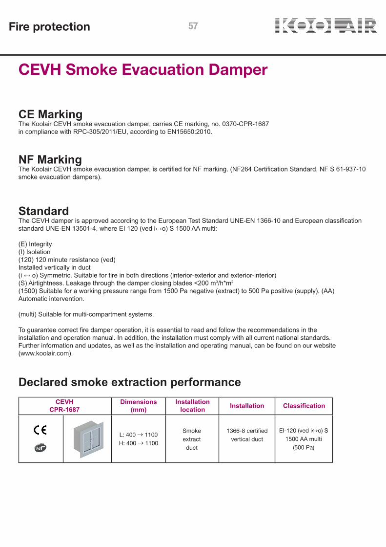
DescriptionSmoke evacuation damper with 2-blade (2P), double door typeswiveling closure, designed to be used for the supply of primary airand smoke evacuation in buildings with high levels of public footfalland in high-rise buildings. Approved in accordance with test standardUNE EN 1366-10 and classified according to EN 13501-4: EI120(ved i↔o) S 1500 AA multi.
Designed according to EN 12101-8 specifications. Composed of astructure with a refractory material externally, sheet steel internallyand two hinged doors made of a refractory material.
Installed vertically within the wall or in a vertical smoke evacuationduct, with the optional of a metal mounting frame previouslyfastened to the duct.
Includes an RPK protective and decorative grille, specific for smokeevacuation and manufactured with anodised aluminium profiles,fitted to the front side of the damper, i.e. the side on display in thebuilding.
Can be used for smoke extraction and air intake (air flow ineither direction)..CEVH smoke evacuation dampers carry CE marking No. 0370-CPR-1687 in accordance with the Construction Product Directive89/106/EEC, according to EN12101-8.
OperationOperation (opening) by means of electric shunt release coil withmanual reset (closing) (CE and NF marking). Optional limitswitch/es:Types of coil (electromagnet) available: 24V electric shunt release coil DC 48V electric shunt release coil DC 24V electric shunt release coil AC 48V electric shunt release coil AC
The operating and reset mechanism is incorporated in the centralpart of the damper where it is protected from smoke and high temperatures.
Fire protection56
L: 400 → 1100H: 400 → 1100
EI-120 (ved i↔o) S 1500 AA multi
(500 Pa)
CEVH Smoke Evacuation Damper
StandardThe CEVH damper is approved according to the European Test Standard UNE-EN 1366-10 and European classificationstandard UNE-EN 13501-4, where EI 120 (ved i↔o) S 1500 AA multi:
(E) Integrity(I) Isolation(120) 120 minute resistance (ved)Installed vertically in duct(i ↔ o) Symmetric. Suitable for fire in both directions (interior-exterior and exterior-interior)(S) Airtightness. Leakage through the damper closing blades <200 m3/h*m2
(1500) Suitable for a working pressure range from 1500 Pa negative (extract) to 500 Pa positive (supply). (AA)Automatic intervention.
(multi) Suitable for multi-compartment systems.
To guarantee correct fire damper operation, it is essential to read and follow the recommendations in theinstallation and operation manual. In addition, the installation must comply with all current national standards.Further information and updates, as well as the installation and operating manual, can be found on our website(www.koolair.com).
CE MarkingThe Koolair CEVH smoke evacuation damper, carries CE marking, no. 0370-CPR-1687in compliance with RPC-305/2011/EU, according to EN15650:2010.
NF MarkingThe Koolair CEVH smoke evacuation damper, is certified for NF marking. (NF264 Certification Standard, NF S 61-937-10smoke evacuation dampers).
Declared smoke extraction performance
Smokeextractduct
1366-8 certifiedvertical duct
CEVHCPR-1687
Installationlocation Installation ClassificationDimensions
(mm)
Fire protection 57

CEVH Smoke Evacuation DamperDimensions
Damper Drawing
Dimensions and openings
Dimensions in mm
Nominallength
Ln (mm)
Exteriorlength
Lt (mm)
Nominal height Hn (mm)
Exterior heightHt (mm)
400 429 400 429
450 479 450 479
500 529 500 529
550 579 550 579
600 629 600 629
650 679 650 679
700 729 700 729
750 779 750 779
800 829 800 829
850 879 850 879
900 929 900 929
950 979 950 979
1000 1029 1000 1029
1050 1079 1050 1079
1100 1129 1100 1129
Ln
Lt
Lt
P
Hn
Ht
Coil protection plate
Ln
Fire protection58
Ln + 10
Hn +
10
Ht
Lt
P *
* P = (Ln / 2) + 90
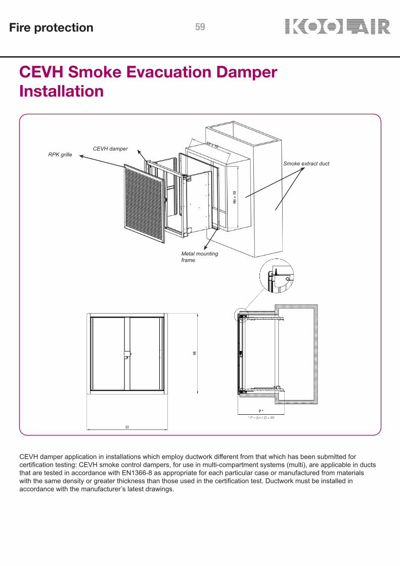
CEVH Smoke Evacuation DamperInstallation
CEVH damper application in installations which employ ductwork different from that which has been submitted forcertification testing: CEVH smoke control dampers, for use in multi-compartment systems (multi), are applicable in ductsthat are tested in accordance with EN1366-8 as appropriate for each particular case or manufactured from materialswith the same density or greater thickness than those used in the certification test. Ductwork must be installed inaccordance with the manufacturer’s latest drawings.
RPK grilleCEVH damper
Metal mountingframe
Smoke extract duct
Fire protection 59
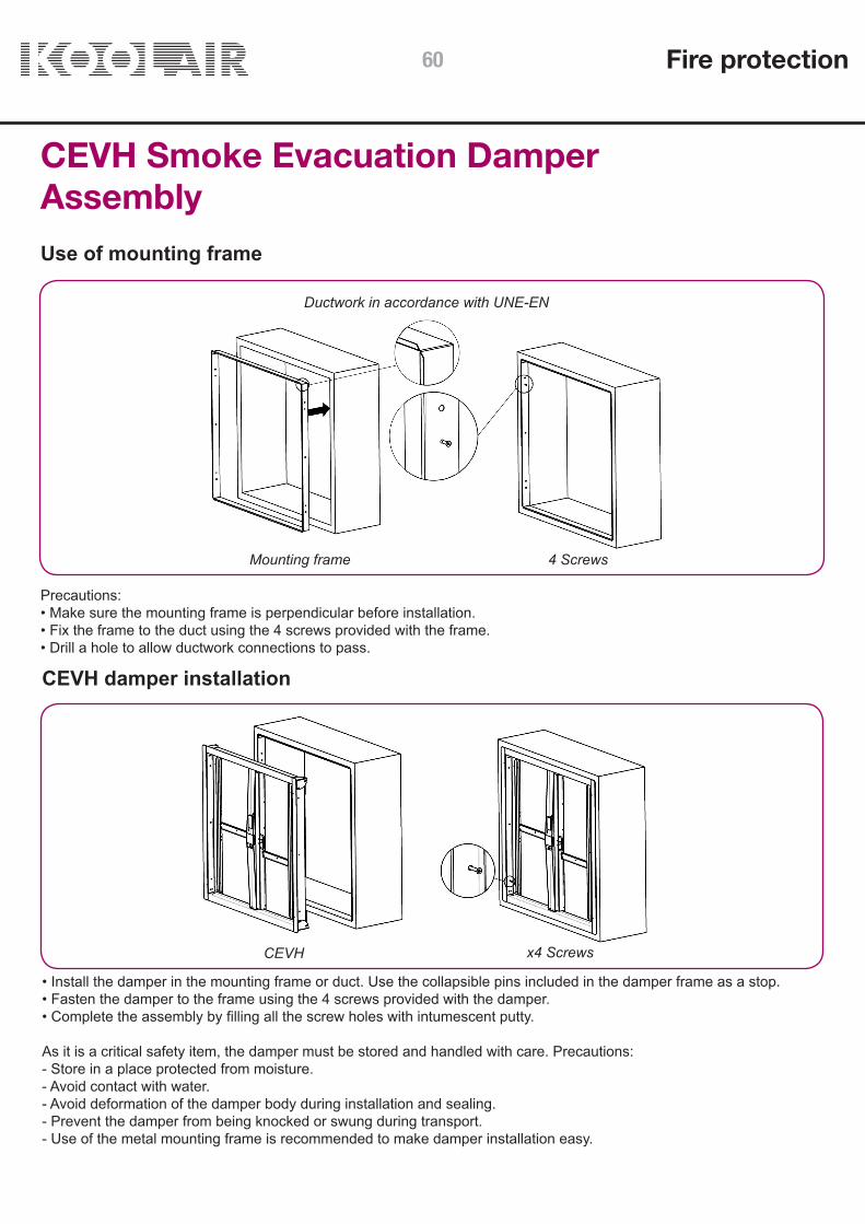
CEVH Smoke Evacuation DamperAssemblyUse of mounting frame
Ductwork in accordance with UNE-EN
Mounting frame
Precautions:• Make sure the mounting frame is perpendicular before installation.• Fix the frame to the duct using the 4 screws provided with the frame.• Drill a hole to allow ductwork connections to pass.
CEVH damper installation
• Install the damper in the mounting frame or duct. Use the collapsible pins included in the damper frame as a stop.• Fasten the damper to the frame using the 4 screws provided with the damper.• Complete the assembly by filling all the screw holes with intumescent putty.
As it is a critical safety item, the damper must be stored and handled with care. Precautions:- Store in a place protected from moisture.- Avoid contact with water.- Avoid deformation of the damper body during installation and sealing.- Prevent the damper from being knocked or swung during transport.- Use of the metal mounting frame is recommended to make damper installation easy.
CEVH x4 Screws
4 Screws
Fire protection60

CEVH Smoke Evacuation DamperConnectionsElectrical connections
FCU: safety position (end of run) one-pole contact.DCU: waiting position (start of run) one-pole contact.FCB: safety position (end of run) two-pole contact.DCB: waiting position (start of run) two-pole contact.
Access to coil’selectrical connectionsand start and end ofrun switches
• Activation by electric shunt release (current driven) coil: - Power supply options 24V DC electric shunt release coil 48V DC electric shunt release coil 24V AC electric shunt release coil 48V AC electric shunt release coil
* CE Marking does not require duplication of the start (DCU, DCB) and end of run limit switch (FCU, FCB).
COIL(Supply type)
COIL(Supply type)
Fire protection
Connection box 1
Connection box 1NF Marking *
Connection box 2
Connection box 2
61

CEVH Smoke Evacuation DamperTechnical Data
Ln
LtHn
Ht
KEYP = Blade depth.Lt = Total exterior length. Ht = Total exterior height.Lh = Interior duct length.Hh = Interior duct height.Ln = Nominal damper length.Hn = Nominal damper height.
Free area table (dm2)
400 450 500 550 600 650 700 750 800 850 900 950 1000 1050 1100
400 9,24 10,76 12,28 13,80 15,3 16,8 18,4 19,9 21,4 22,9 24,4 26,0 27,5 29,0 30,5 450 10,76 12,53 14,30 16,07 17,8 19,6 21,4 23,2 24,9 26,7 28,5 30,2 32,0 33,8 35,5 500 12,28 14,30 16,32 18,34 20,4 22,4 24,4 26,4 28,4 30,5 32,5 34,5 36,5 38,5 40,6 550 13,80 16,07 18,34 20,61 22,9 25,2 27,4 29,7 32,0 34,2 36,5 38,8 41,0 43,3 45,6 600 15,32 17,84 20,36 22,88 25,4 27,9 30,4 33,0 35,5 38,0 40,5 43,0 45,6 48,1 50,6 650 16,84 19,61 22,38 25,15 27,9 30,7 33,5 36,2 39,0 41,8 44,5 47,3 50,1 52,9 55,6 700 18,36 21,38 24,40 27,42 30,4 33,5 36,5 39,5 42,5 45,5 48,6 51,6 54,6 57,6 60,6 750 19,88 23,15 26,42 29,69 33,0 36,2 39,5 42,8 46,0 49,3 52,6 55,9 59,1 62,4 65,7 800 21,40 24,92 28,44 31,96 35,5 39,0 42,5 46,0 49,6 53,1 56,6 60,1 63,6 67,2 70,7 850 22,92 26,69 30,46 34,23 38,0 41,8 45,5 49,3 53,1 56,9 60,6 64,4 68,2 71,9 75,7 900 24,44 28,46 32,48 36,50 40,5 44,5 48,6 52,6 56,6 60,6 64,6 68,7 72,7 76,7 80,7 950 25,96 30,23 34,50 38,77 43,0 47,3 51,6 55,9 60,1 64,4 68,7 72,9 77,2 81,5 85,7 1000 27,48 32,00 36,52 41,04 45,6 50,1 54,6 59,1 63,6 68,2 72,7 77,2 81,7 86,2 90,8 1050 29,00 33,77 38,54 43,31 48,1 52,9 57,6 62,4 67,2 71,9 76,7 81,5 86,2 91,0 95,8 1100 30,52 35,54 40,56 45,58 50,6 55,6 60,6 65,7 70,7 75,7 80,7 85,7 90,8 95,8 101
Length Ln (in mm)
Fire protection62

0
5
10
15
20
25
30
35
0 1 2 3 4 5 6 7 8 9 10
ΔP e
st
Vp
CEVH Vp-ΔPest
CEVH Smoke Evacuation DamperTechnical DataCEVH Graph
Selection example:To calculate the static pressure loss across a CEVH damper for a given flow rate Q(m3/h) the air velocity Vp(m/s) iscalculated in relation to the damper air passage (dm2) as free area table. Usingthis area and a given flow rate, the air velocity is obtained, which, when introduced in the previous graph gives the pressure loss.Example:A damper with nominal dimensions of 600x600 mm we will have a free area of 25.4 dm2. For a design flow rate of 5000 m3/h3, the flow velocity is calculated using the formula Vp = (Q / air pass) / 36.In this case the Vp = 5.46 m / s that introduced in the previous table would give us a static load loss ΔPest. = 9Pa.
Key:Vp damper air velocity in m/s. damper static pressure.ΔPest loss in Pa.
Fire protection 63

CEVH Smoke Evacuation Damper Coding
Damper dimensions and model
CEVH – L x H (mm)
Activation. Components
+ SHUNT RELEASE 24 V DC + ER/SR LS+ SHUNT RELEASE 48 V DC + ER/SR LS+ SHUNT RELEASE 24 V AC + ER/SR LS+ SHUNT RELEASE 48 V AC + ER/SR LS
Accessories
MM (Metal mounting frame)RPK (protective smoke evacuation grille)
Fire protection64

Smoke Evacuation DamperCEVH-1P
CONTENTS
Description 66Dimensions 68Installation 70Conexions 72Technical data 73Coding 76
Fire protection 65

CEVH-1P Smoke Evacuation Damper
DescriptionSmoke evacuation damper with 1-blade (1P), single door type swiveling closure, designed to be used for the supply of primary air and smoke evacuation in buildings with high levels of public footfall and in high-rise buildings. Approved in accordance with test standard UNE EN 1366-10 and classified according to EN 13501-4: EI120 (ved i↔o) S 1500 AA multi.
Designed according to EN 12101-8 specifications.Composed of a structure with a refractory material externally, sheet steel internally and one hinged door made of a refractory material.
Installed in a vertical smoke evacuation duct, with the optional of a metal mounting frame previously fastened to the duct.
The rearm of the damper can be manual or motorized.
Can include an RPK protective and decorative grille, specific for smoke evacuation and manufactured with anodised aluminium profiles, or a DECO decorative plate, manufactured with refractory material. Both fitted to the front side of the damper, i.e. the side on display in the building.Can be used for smoke extraction and air intake (air flow in either direction).
CEVH-1P smoke evacuation dampers carry CE marking No. 0370-CPR-3051 in accordance with the Construction Product Directive RPC-305, according to EN12101-8.
OperationOperation (opening) by means of electric shunt release coil with manual reset (closing) (CE marking). Optional limit switch/es:
Types of coil (electromagnet) available:
• 24V electric shunt release coil DC • 48V electric shunt release coil DC • 24V electric shunt release coil AC • 48V electric shunt release coil AC • 220V electric shunt release coil AC
The operating and reset mechanism is incorporated in the front part of the damper where it is protected from smoke and high temperatures.
Fire protection66

L: 300 → 700H: 385 → 1100
EI-120 (ved i↔o) S 1500 AA multi
(500 Pa)
CEVH-1P Smoke Evacuation Damper
StandardThe CEVH-1P damper is approved according to the European Test Standard UNE-EN 1366-10 and European classification standard UNE-EN 13501-4, where EI 120 (ved i↔o) S 1500 AA multi:
(E) Integrity(I) Isolation(120) 120 minute resistance(ved) Installed vertically in duct(i ↔ o) Symmetric. Suitable for fire in both directions (interior-exterior and exterior-interior)(S) Airtightness. Leakage through the damper closing blades <200 m3/h*m2
(1500) Suitable for a working pressure range from 1500 Pa negative (extract) to 500 Pa positive (supply).(AA) Automatic intervention.(multi) Suitable for multi-compartment systems.
To guarantee correct fire damper operation, it is essential to read and follow the recommendations in the installation and operation manual. In addition, the installation must comply with all current national standards.
Further information and updates, as well as the installation and operating manual, can be found on our website (www.koolair.com).
CE MarkingThe Koolair CEVH-1P smoke evacuation damper, carries CE marking, no. 0370-CPR-3051 in compliance with RPC-305, according to EN12101-8.
Declared smoke extraction performance
Smokeextractduct
1366-8 certifiedvertical duct
CEVH-1PCPR-3051
Installationlocation Installation ClassificationDimensions
(mm)
Fire protection 67

CEVH-1P Smoke Evacuation DamperDimensions
Damper Drawing
Dimensions and openings
Nominallength
Ln (mm)
Outside length Lt[mm]
[mm] DECO RPK RPK-1A RPK-2A RPK-X RPK-P RPK-S300 350 394 394 434 410 434 394
350 400 444 444 484 460 484 444
400 450 494 494 534 510 534 494
450 500 544 544 584 560 584 544
500 550 594 594 634 610 634 594
550 600 644 644 684 660 684 644
600 650 694 694 734 710 734 694
650 700 744 744 784 760 784 744
700 750 794 794 834 810 834 794
Lt Lt155 15536 7
Ht HtHn Hn Hn
Manual + RPK / Motorized + RPK Manual + Deco / Motorized + Deco
Ln
Fire protection68
CEVH-1P Smoke Evacuation DamperDimensions
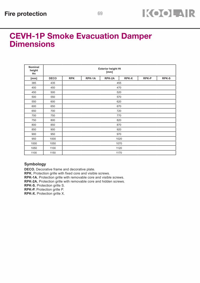
Nominal height
Hn
Exterior height Ht[mm]
[mm] DECO RPK RPK-1A RPK-2A RPK-X RPK-P RPK-S385 435 455
400 450 470
450 500 520
500 550 570
550 600 620
600 650 670
650 700 720
700 750 770
750 800 820
800 850 870
850 900 920
900 950 970
950 1000 1020
1000 1050 1070
1050 1100 1120
1100 1150 1170
SymbologyDECO. Decorative frame and decorative plate.RPK. Protection grille with fixed core and visible screws.RPK-1A. Protection grille with removable core and visible screws.RPK-2A. Protection grille with removable core and hidden screws.RPK-S. Protection grille S.RPK-P. Protection grille P.RPK-X. Protection grille X.
Fire protection 69

Ln + 10
Hn +
10
Ht
Lt
Ht
Ln + 110 > 110
CEVH-1P Smoke Evacuation DamperInstallation
CEVH-1P damper application in installations which employ ductwork different from that which has been submitted for certification testing:
CEVH-1P smoke control dampers, for use in multi-compartment systems (multi), are applicable in ducts that are tested in accordance with EN1366-8 as appropriate for each particular case or manufactured from materials with the same density or greater thickness than those used in the certification test. Ductwork must be installed in accordance with the manufacturer’s latest drawings.
RPK grille
CEVH-1P damper
Metal mountingframe
Smoke extract duct
Fire protection70

CEVH-1P Smoke Evacuation DamperAssemblyUse of mounting frame
Ductwork in accordance with UNE-EN 1366-8
Install the mounting frame and fix it with 4 screws.
Install the mounting frame and fix it with 4 screws.
Precautions:• Make sure the mounting frame is perpendicular before installation.• Fix the frame to the duct using the 4 screws provided with the frame.• Drill a hole to allow ductwork connections to pass.
CEVH-1P damper installation
• Install the damper in the mounting frame or duct. Use the collapsible pins included in the damper frame as a stop.• Fasten the damper to the frame using the 4 screws provided with the damper.• Complete the assembly by filling all the screw holes with intumescent putty.
As it is a critical safety item, the damper must be stored and handled with care. Precautions:- Store in a place protected from moisture.- Avoid contact with water.- Avoid deformation of the damper body during installation and sealing.- Prevent the damper from being knocked or swung during transport.- Use of the metal mounting frame is recommended to make damper installation easy.
Fire protection 71

CEVH-1P Smoke Evacuation DamperConnectionsElectrical connections
Access to coil’s inside the connection box: • Shunt • Start and end switches. • Motor (Depending on model).
B-IMP (Shunt rel).
FDCU (beginning and end of run): security position contact and waiting.
FCU: safety position (end of run) one-pole contact.
DCU: waiting position (start of run) one-pole contact.
Operated by electric shunt release (current driven) coil and manual rearm or motorized:• Power supply options for manual and motorized reset: o 24V electric shunt release coil DC o 48V electric shunt release coil DC o 24V electric shunt release coil AC o 48V electric shunt release coil AC o 220V electric shunt release coil AC
• Motor for motorized rearming: o Servomotor BL-24/48 V – DC / AC
* CE Marking does not require duplication of the start (DCU, DCB) and end of run limit switch (FCU, FCB).
Connection box
Connection box
Fire protection72
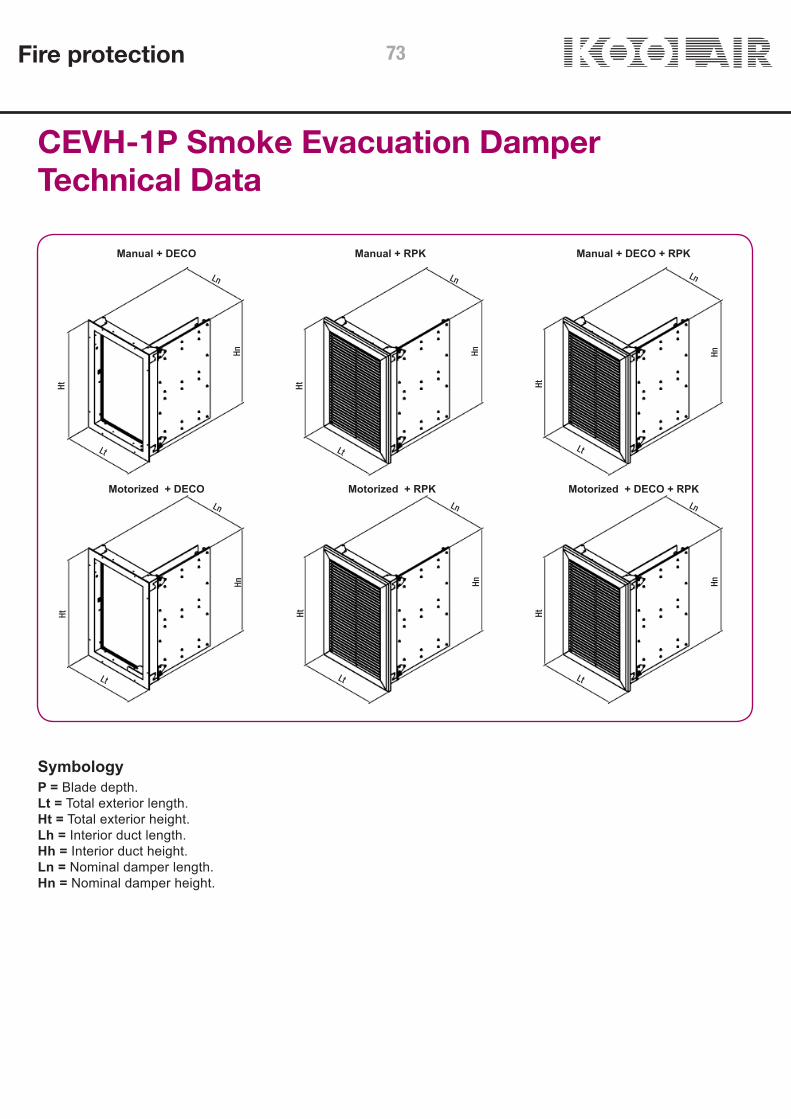
CEVH-1P Smoke Evacuation DamperTechnical Data
Ln Ln Ln
LnLnLn
Lt Lt Lt
LtLtLt
Hn Hn HnHnHnHn
Ht Ht HtHtHtHt
SymbologyP = Blade depth.Lt = Total exterior length. Ht = Total exterior height.Lh = Interior duct length.Hh = Interior duct height.Ln = Nominal damper length.Hn = Nominal damper height.
Manual + DECO
Motorized + DECO
Manual + DECO + RPK
Motorized + DECO + RPK
Manual + RPK
Motorized + RPK
Fire protection 73

CEVH-1P Smoke Evacuation DamperTechnical DataFree area table (m2) Manual
300 350 400 450 500 550 600 650 700
385 0,12 0,13 0,15 0,17 0,19 0,21 0,23 0,25 0,27 400 0,12 0,14 0,16 0,18 0,20 0,22 0,24 0,26 0,28 450 0,14 0,16 0,18 0,2025 0,225 0,2475 0,27 0,2925 0,315 500 0,15 0,18 0,20 0,225 0,25 0,275 0,30 0,325 0,35 550 0,17 0,19 0,22 0,2475 0,275 0,3025 0,33 0,3575 0,385 600 0,18 0,21 0,24 0,27 0,30 0,33 0,36 0,39 0,42 650 0,20 0,23 0,26 0,2925 0,325 0,3575 0,39 0,4225 0,455 700 0,21 0,25 0,28 0,315 0,35 0,385 0,42 0,455 0,49 750 0,23 0,26 0,30 0,3375 0,375 0,4125 0,45 0,4875 0,525 800 0,24 0,28 0,32 0,36 0,40 0,44 0,48 0,52 0,56 850 0,26 0,30 0,34 0,3825 0,425 0,4675 0,51 0,5525 0,595 900 0,27 0,32 0,36 0,405 0,45 0,495 0,54 0,585 0,63 950 0,29 0,33 0,38 0,4275 0,475 0,5225 0,57 0,6175 0,665 1000 0,30 0,35 0,40 0,75 0,50 0,55 0,60 0,65 0,70 1050 0,32 0,37 0,42 0,4725 0,525 0,5775 0,63 0,6825 0,735 1100 0,33 0,39 0,44 0,495 0,55 0,605 0,66 0,715 0,77
Length Ln (in mm)Height Hn
(in mm)
Free area table (m2) Motorized
400 450 500 550 600 650 700
400 0,15 0,17 0,19 0,21 0,23 0,25 0,27 450 0,17 0,19 0,22 0,24 0,26 0,28 0,31 500 0,19 0,22 0,24 0,27 0,29 0,32 0,34 550 0,21 0,24 0,27 0,29 0,32 0,35 0,38 600 0,23 0,26 0,29 0,32 0,35 0,38 0,41 650 0,25 0,28 0,32 0,35 0,38 0,41 0,45 700 0,27 0,31 0,34 0,38 0,41 0,45 0,48 750 0,29 0,33 0,37 0,40 0,44 0,48 0,52 800 0,31 0,35 0,39 0,43 0,47 0,51 0,55 850 0,33 0,37 0,42 0,46 0,50 0,54 0,59 900 0,35 0,40 0,44 0,49 0,53 0,58 0,62 950 0,37 0,42 0,47 0,51 0,56 0,61 0,66 1000 0,39 0,44 0,49 0,54 0,59 0,64 0,69 1050 0,41 0,46 0,52 0,57 0,62 0,67 0,73 1100 0,43 0,49 0,54 0,60 0,65 0,71 0,76
Length Ln (in mm)Height Hn
(in mm)
Fire protection74

0
10
20
30
40
50
60
70
80
0 1 2 3 4 5 6 7 8 9 10 11 12 13 14 15
ΔPe
st
Vp
CEVH-1P Vp-ΔPest
CEVH-1P Smoke Evacuation DamperTechnical DataCEVH-1P Graph
Selection example:To calculate the static pressure loss across a CEVH-1P damper for a given flow rate Q [m3/h] the air velocity Vp [m/s] is calculated in relation to the damper air passage [m2] as free area table. Using this area and a given flow rate, the air velocity is obtained, which, when introduced in the previous graph gives the pressure loss.Example:A damper with nominal dimensions of 700x1000 mm we will have a free area of 0,7 m2. or a design flow rate of 10000 m3/h the flow velocity is calculated using the formula:
In this case the Vp = 3,96 m/s that introduced in the previous table would give us a static load los ΔPest= 7 Pa.
Symbology:Vp Damper air velocity in m/s.ΔPest Damper static pressure loss in Pa.
Fire protection 75
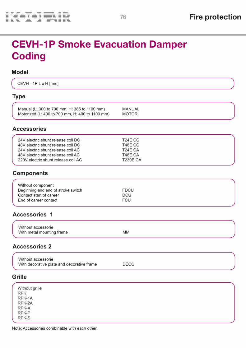
CEVH-1P Smoke Evacuation DamperCodingModel
CEVH - 1P L x H [mm]
Type
Components
Accessories 1
Accessories 2
Manual (L: 300 to 700 mm, H: 385 to 1100 mm) MANUALMotorized (L: 400 to 700 mm, H: 400 to 1100 mm) MOTOR
Without component Beginning and end of stroke switch FDCUContact start of career DCUEnd of career contact FCU
Without accessorie With metal mounting frame MM
Without accessorie With decorative plate and decorative frame DECO
Accessories
24V electric shunt release coil DC T24E CC48V electric shunt release coil DC T48E CC24V electric shunt release coil AC T24E CA48V electric shunt release coil AC T48E CA220V electric shunt release coil AC T230E CA
Note: Accessories combinable with each other.
Grille
Without grilleRPKRPK-1ARPK-2ARPK-XRPK-PRPK-S
Fire protection76

CEVH-1P Smoke Evacuation DamperCoding
Finishes
Length
Height
Without treatmentAnodised natural mattPainted RAL-9016 mattPainted RAL-9016 shinePainted RAL-9005 mattPainted RAL-9005 shinePrepared for paintingPainted RAL-9010 mattPainted RAL-9010 shinePainted RAL-7042Anodised s/notePainted s/note
300350400450500550600650700
385400450500550600650700750800850900950100010201100
Fire protection 77

RPK Cover grillefor smoke dampers
CONTENTS
Description and dimensions 79 Coding, mounting and technical data 70
Fire protection78

Cover grille RPK for smoke dampers
DescriptionRPK Cover grille manufactured from natural anodised aluminium, specifically developed for protection of Koolair smoke dampers SMLD & CEVH.The grille has been designed for surface mounting and its central core has been developed to reduce pressure drop.Two versions are currently available: Fixed central core and removable central core (with 2 fixing variations).
ApplicationFor protection of Koolair smoke dampers types SMLD and CEVH. They can be used in both supply and extract applications. Grille comprises of an aluminium frame with curved aluminium blades. The grille can be fixed by screws in the versions with fixed core and removable core, the removable core version can also be fixed with concealed fixings.
FinishesAnodised natural aluminium, special finishes available upon request.
Identification RPK Series, aluminium grille.
Dimensions
RPKFIX GRILLE AND
VISIBLE SCREWS
L (EXT.)
H (E
XT.)
H (E
XT.)
H (E
XT.)
H (E
XT.)
116
116 116
116
130
130
136 13
6
136
136
116
116
H (E
XT.)
H (E
XT.)
40 40 6040
40 4840 60 60 48
40 60
L (EXT.) L (EXT.)
L (EXT.) L (EXT.) L (EXT.)
RPK-SFIX GRILLE AND
VISIBLE SCREWS
RPK-1AREMOVABLE GRILLE
ANDVISIBLE SCREWS
RPK-PFIX GRILLE AND
HIDDEN SCREWS
RPK-2AREMOVABLE GRILLE
AND HIDDEN SCREWS
RPK-XFOLDING GRILLE
AND HIDDEN SCREWS
Fire protection 79

Coding
RPK: Protection grille with fixed central core.RPK - 1A: Protection grille with removable core (visible screws).RPK - 2A: Protection grille with removable core (hidden screws).RPK-X: Protection grille with folding core (hidden screws).RPK-P: Protection grille with fixed central core (hidden screws).RPK-S: Protection grille with fixed central core (visible screws).
RPK + SMLD
Mounting and technical data
MOUNTING FRAME
MOUNTING FRAME
RPK
SEAL WITHRF MASTIC
DUCT AS NORM UNE-EN1366-8
MOUNTING FRAME
RPK DAMPER SMLDMECHANISM DRIVE
DUCT AS NORM UNE-EN1366-8
FREE AREA TABLE RPK (dm2 )
Ln (mm)Height Hn (mm)
200 250 300 350 400 450 500 550 600 650 700 750 800 850 900 950 1000
354 5,7 7,1 8,6 10,0 11,4 12,9 14,3 15,7 17,2 18,6 20,0 21,4 22,9 24,3 25,7 27,2 28,6
527 8,5 10,6 12,8 14,9 17,0 19,2 21,3 23,4 25,5 27,7 29,8 31,9 34,1 36,2 38,3 40,4 42,6
700 11,3 14,1 17,0 19,8 22,6 25,4 28,3 31,1 33,9 36,8 39,6 42,4 45,2 48,1 50,9 53,7 56,5
LegendL: LengthH: HeightLn: Nominal lengthHn: Nominal heightLt: Total lengthHt: Total heightLm: Mounting frame lengthHm: Mounting frame heightLh: Opening lengthHh: Opening height
Height dimensionsH = HnHt = Hn + 249Hm = Hn + 255Hh = Hn + 257
Fire protection80
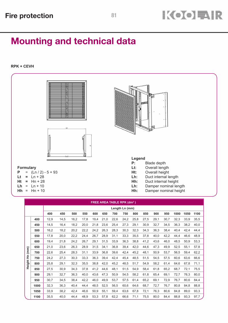
RPK + CEVH
Mounting and technical data
LegendP: Blade depthLt: Overall lengthHt: Overall heightLh: Duct internal lengthHh: Duct internal heightLh: Damper nominal lengthHh: Damper nominal height
FormularyP = (Ln / 2) - 5 + 93Lt = Ln + 28Ht = Hn + 28Lh = Ln + 10Hh = Hn + 10
FREE AREA TABLE RPK (dm2 )
Length Ln (mm)400 450 500 550 600 650 700 750 800 850 900 950 1000 1050 1100
Hei
ght H
n (m
m)
400 12,9 14,5 16,2 17,8 19,4 21,0 22,6 24,2 25,8 27,5 29,1 30,7 32,3 33,9 35,5
450 14,5 16,4 18,2 20,0 21,8 23,6 25,4 27,3 29,1 30,9 32,7 34,5 36,3 38,2 40,0
500 16,2 18,2 20,2 22,2 24,2 26,3 28,3 30,3 32,3 34,3 36,3 38,4 40,4 42,4 44,4
550 17,8 20,0 22,2 24,4 26,7 28,9 31,1 33,3 35,5 37,8 40,0 42,2 44,4 46,6 48,9
600 19,4 21,8 24,2 26,7 29,1 31,5 33,9 36,3 38,8 41,2 43,6 46,0 48,5 50,9 53,3
650 21,0 23,6 26,3 28,9 31,5 34,1 36,8 39,4 42,0 44,6 47,3 49,9 52,5 55,1 57,8
700 22,6 25,4 28,3 31,1 33,9 36,8 39,6 42,4 45,2 48,1 50,9 53,7 56,5 59,4 62,2
750 24,2 27,3 30,3 33,3 36,3 39,4 42,4 45,4 48,5 51,5 54,5 57,5 60,6 63,6 66,6
800 25,8 29,1 32,3 35,5 38,8 42,0 45,2 48,5 51,7 54,9 58,2 61,4 64,6 67,8 71,1
850 27,5 30,9 34,3 37,8 41,2 44,6 48,1 51,5 54,9 58,4 61,8 65,2 68,7 72,1 75,5
900 29,1 32,7 36,3 40,0 43,6 47,3 50,9 54,5 58,2 61,8 65,4 69,1 72,7 76,3 80,0
950 30,7 34,5 38,4 42,2 46,0 49,9 53,7 57,5 61,4 65,2 69,1 72,9 76,7 80,6 84,4
1000 32,3 36,3 40,4 44,4 48,5 52,5 56,5 60,6 64,6 68,7 72,7 76,7 80,8 84,8 88,8
1050 33,9 38,2 42,4 46,6 50,9 55,1 59,4 63,6 67,8 72,1 76,3 80,6 84,8 89,0 93,3
1100 35,5 40,0 44,4 48,9 53,3 57,8 62,2 66,6 71,1 75,5 80,0 84,4 88,8 93,3 97,7
Fire protection 81
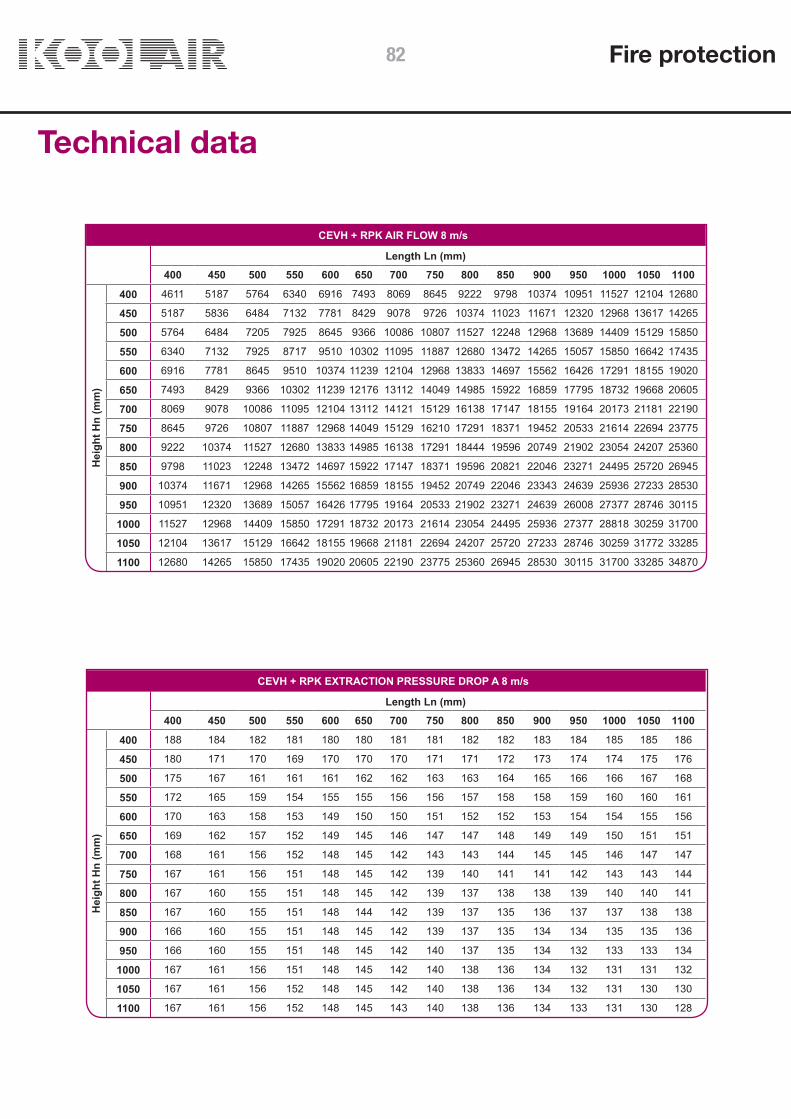
Technical data
CEVH + RPK AIR FLOW 8 m/s
Length Ln (mm)400 450 500 550 600 650 700 750 800 850 900 950 1000 1050 1100
Hei
ght H
n (m
m)
400 4611 5187 5764 6340 6916 7493 8069 8645 9222 9798 10374 10951 11527 12104 12680
450 5187 5836 6484 7132 7781 8429 9078 9726 10374 11023 11671 12320 12968 13617 14265
500 5764 6484 7205 7925 8645 9366 10086 10807 11527 12248 12968 13689 14409 15129 15850
550 6340 7132 7925 8717 9510 10302 11095 11887 12680 13472 14265 15057 15850 16642 17435
600 6916 7781 8645 9510 10374 11239 12104 12968 13833 14697 15562 16426 17291 18155 19020
650 7493 8429 9366 10302 11239 12176 13112 14049 14985 15922 16859 17795 18732 19668 20605
700 8069 9078 10086 11095 12104 13112 14121 15129 16138 17147 18155 19164 20173 21181 22190
750 8645 9726 10807 11887 12968 14049 15129 16210 17291 18371 19452 20533 21614 22694 23775
800 9222 10374 11527 12680 13833 14985 16138 17291 18444 19596 20749 21902 23054 24207 25360
850 9798 11023 12248 13472 14697 15922 17147 18371 19596 20821 22046 23271 24495 25720 26945
900 10374 11671 12968 14265 15562 16859 18155 19452 20749 22046 23343 24639 25936 27233 28530
950 10951 12320 13689 15057 16426 17795 19164 20533 21902 23271 24639 26008 27377 28746 30115
1000 11527 12968 14409 15850 17291 18732 20173 21614 23054 24495 25936 27377 28818 30259 31700
1050 12104 13617 15129 16642 18155 19668 21181 22694 24207 25720 27233 28746 30259 31772 33285
1100 12680 14265 15850 17435 19020 20605 22190 23775 25360 26945 28530 30115 31700 33285 34870
CEVH + RPK EXTRACTION PRESSURE DROP A 8 m/s
Length Ln (mm)400 450 500 550 600 650 700 750 800 850 900 950 1000 1050 1100
Hei
ght H
n (m
m)
400 188 184 182 181 180 180 181 181 182 182 183 184 185 185 186
450 180 171 170 169 170 170 170 171 171 172 173 174 174 175 176
500 175 167 161 161 161 162 162 163 163 164 165 166 166 167 168
550 172 165 159 154 155 155 156 156 157 158 158 159 160 160 161
600 170 163 158 153 149 150 150 151 152 152 153 154 154 155 156
650 169 162 157 152 149 145 146 147 147 148 149 149 150 151 151
700 168 161 156 152 148 145 142 143 143 144 145 145 146 147 147
750 167 161 156 151 148 145 142 139 140 141 141 142 143 143 144
800 167 160 155 151 148 145 142 139 137 138 138 139 140 140 141
850 167 160 155 151 148 144 142 139 137 135 136 137 137 138 138
900 166 160 155 151 148 145 142 139 137 135 134 134 135 135 136
950 166 160 155 151 148 145 142 140 137 135 134 132 133 133 134
1000 167 161 156 151 148 145 142 140 138 136 134 132 131 131 132
1050 167 161 156 152 148 145 142 140 138 136 134 132 131 130 130
1100 167 161 156 152 148 145 143 140 138 136 134 133 131 130 128
Fire protection82

SCDC Smoke Evacuation Damper
CONTENTS
Description 84Connections 85Dimensions 87Selection chart 88Installation 89Coding 90
Fire protection 83
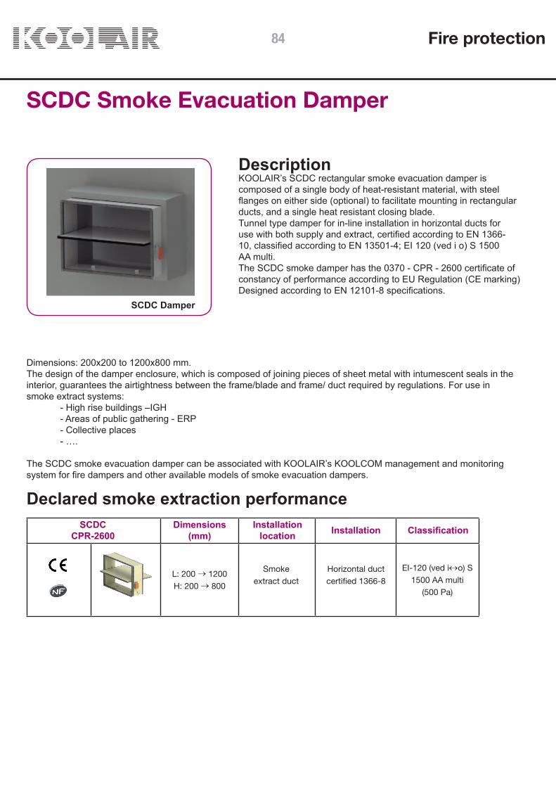
L: 200 → 1200H: 200 → 800
EI-120 (ved i↔o) S 1500 AA multi
(500 Pa)
SCDC Smoke Evacuation Damper
DescriptionKOOLAIR’s SCDC rectangular smoke evacuation damper iscomposed of a single body of heat-resistant material, with steelflanges on either side (optional) to facilitate mounting in rectangularducts, and a single heat resistant closing blade.Tunnel type damper for in-line installation in horizontal ducts foruse with both supply and extract, certified according to EN 1366-10, classified according to EN 13501-4; EI 120 (ved i o) S 1500AA multi.The SCDC smoke damper has the 0370 - CPR - 2600 certificate ofconstancy of performance according to EU Regulation (CE marking)Designed according to EN 12101-8 specifications.
Dimensions: 200x200 to 1200x800 mm.The design of the damper enclosure, which is composed of joining pieces of sheet metal with intumescent seals in theinterior, guarantees the airtightness between the frame/blade and frame/ duct required by regulations. For use insmoke extract systems: - High rise buildings –IGH - Areas of public gathering - ERP - Collective places - ….
The SCDC smoke evacuation damper can be associated with KOOLAIR’s KOOLCOM management and monitoringsystem for fire dampers and other available models of smoke evacuation dampers.
SCDC Damper
Declared smoke extraction performance
Smokeextract duct
Horizontal ductcertified 1366-8
SCDCCPR-2600
Installationlocation Installation ClassificationDimensions
(mm)
Fire protection84

SCDC Smoke Evacuation DamperConnectionsOperating mechanism electrical connectionsFCU: safety position (end of run) one-pole contact.DCU: waiting position (start of run) one-pole contact.FCB: safety position (end of run) two-pole contact.DCB: waiting position (start of run) two-pole contact.
- Manual reset, activated by electric coil (CE and NF marking). 24 V DC. electric shunt release coil. 48V DC electric shunt release coil 24V AC electric shunt release coil 48V AC electric shunt release coil
Option to incorporate two start of run limit switches (DCU, DCB) and two end of run limit switches (FCU, FCB). The NFMarking requires at least one start of run limit switch (DCU) and one end of run limit switch (FCU).
Connection box 1 Connection box 2
COIL(Supply type)
Connection box 1
Connection box 2
Fire protection 85

Option to incorporate two start of run limit switches (DCU, DCB) and two end of run limit switches (FCU, FCB). The NFMarking requires at least one start of run limit switch (DCU) and one end of run limit switch (FCU).
Connection box 1 Connection box 2
COIL(Supply type)
MOTOR
SCDC Smoke Evacuation DamperConnections- Automatic activation and reset by servomotor (CE Marking):
SCDC smoke extract dampers are activated and reset by means of a servomotor with a supply voltage of 24 V AC/DC (model BLE24) or 230 V AC (model BLE230). These motors include start and end of run limit switches to monitor the opening/closing status of the damper.
• Activated by shunt release coil and reset with electric servomotor (CE and NF marking):
24 V DC electric shunt release coil. 48V DC electric shunt release coil 24V AC electric shunt release coil 48V AC electric shunt release coil Servomotor to reset (close) damper, BL24-48, with 24 ... 48 V AC/DC supply voltage
Connection box
Connection box 1
Connectionbox 2
Fire protection86

SCDC SMOKE DAMPER FREE AREA TABLE dm2
Length Ln (mm)200 250 300 350 400 450 500 550 600 650 700 750 800 850 900 950 1000 1050 1100 1150 1200
Hei
ght H
n (m
m)
200 2,9 3,7 4,5 5,3 6,0 6,8 7,6 8,4 9,1 9,9 10,7 11,5 12,2 13,0 13,8 14,6 15,3 16,1 16,9 17,7 18,4
250 3,9 4,9 5,9 7,0 8,0 9,0 10,0 11,1 12,1 13,1 14,1 15,2 16,2 17,2 18,2 19,3 20,3 21,3 22,3 23,4 24,4
300 4,8 6,1 7,4 8,7 9,9 11,2 12,5 13,8 15,0 16,3 17,6 18,9 20,1 21,4 22,7 24,0 25,2 26,5 27,8 29,1 30,3
350 5,8 7,3 8,8 10,4 11,9 13,4 14,9 16,5 18,0 19,5 21,0 22,6 24,1 25,6 27,1 28,7 30,2 31,7 33,2 34,8 36,3
400 6,7 8,5 10,3 12,1 13,8 15,6 17,4 19,2 20,9 22,7 24,5 26,3 28,0 29,8 31,6 33,4 35,1 36,9 38,7 40,5 42,2
450 7,7 9,7 11,7 13,8 15,8 17,8 19,8 21,9 23,9 25,9 27,9 30,0 32,0 34,0 36,0 38,1 40,1 42,1 44,1 46,2 48,2
500 8,6 10,9 13,2 15,5 17,7 20,0 22,3 24,6 26,8 29,1 31,4 33,7 35,9 38,2 40,5 42,8 45,0 47,3 49,6 51,9 54,1
550 9,6 12,1 14,6 17,2 19,7 22,2 24,7 27,3 29,8 32,3 34,8 37,4 39,9 42,4 44,9 47,5 50,0 52,5 55,0 57,6 60,1
600 10,5 13,3 16,1 18,9 21,6 24,4 27,2 30,0 32,7 35,5 38,3 41,1 43,8 46,6 49,4 52,2 54,9 57,7 60,5 63,3 66,0
650 11,5 14,5 17,5 20,6 23,6 26,6 29,6 32,7 35,7 38,7 41,7 44,8 47,8 50,8 53,8 56,9 59,9 62,9 65,9 69,0 72,0
700 12,4 15,7 19,0 22,3 25,5 28,8 32,1 35,4 38,6 41,9 45,2 48,5 51,7 55,0 58,3 61,6 64,8 68,1 71,4 74,7 77,9
750 13,4 16,9 20,4 24,0 27,5 31,0 34,5 38,1 41,6 45,1 48,6 52,2 55,7 59,2 62,7 66,3 69,8 73,3 76,8 80,4 83,9
800 14,3 18,1 21,9 25,7 29,4 33,2 37,0 40,8 44,5 48,3 52,1 55,9 59,6 63,4 67,2 71,0 74,7 78,5 82,3 86,1 89,8
SCDC Smoke Evacuation DamperDimensions
NOMINAL H H S1 S2
200 200 0 0 250 250 25 0 300 300 50 0 350 350 75 0 400 400 100 0 450 450 125 0 500 500 150 0 550 550 175 7 600 600 200 32 650 650 225 57 700 700 250 82 750 750 275 107 800 800 300 132
NO
MIN
AL +
60
NO
MIN
AL +
20
KeyL: Interior damper length.H: Interior damper height.
Fire protection 87
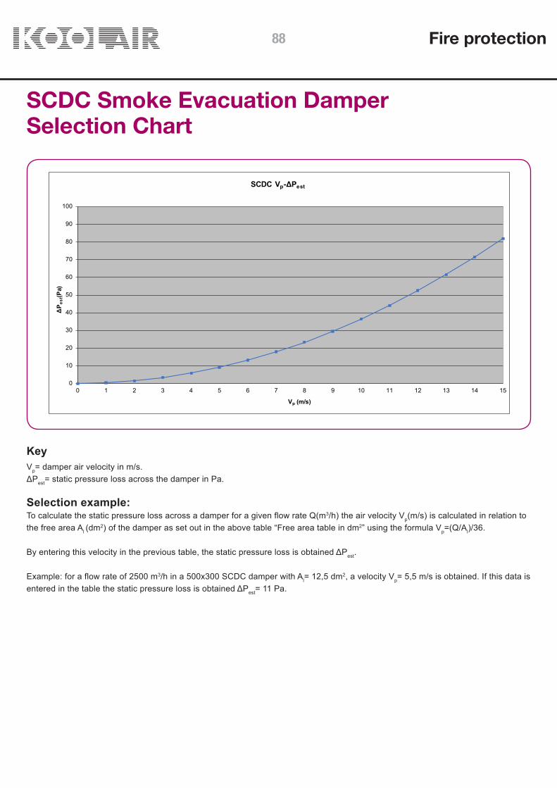
0
10
20
30
40
50
60
70
80
90
100
0 1 2 3 4 5 6 7 8 9 10 11 12 13 14 15
ΔP e
st(P
a)
Vp (m/s)
SCDC Vp-ΔPest
SCDC Smoke Evacuation DamperSelection Chart
KeyVp= damper air velocity in m/s.ΔPest= static pressure loss across the damper in Pa.
Selection example:To calculate the static pressure loss across a damper for a given flow rate Q(m3/h) the air velocity Vp(m/s) is calculated in relation tothe free area Al (dm2) of the damper as set out in the above table “Free area table in dm2” using the formula Vp=(Q/Al)/36.
By entering this velocity in the previous table, the static pressure loss is obtained ΔPest.
Example: for a flow rate of 2500 m3/h in a 500x300 SCDC damper with Al= 12,5 dm2, a velocity Vp= 5,5 m/s is obtained. If this data is entered in the table the static pressure loss is obtained ΔPest= 11 Pa.
Fire protection88

SCDC Smoke Evacuation DamperInstallation
DAMPER BODY
227
MIN 100
139
NO
MIN
AL
+ 60
NO
MIN
AL
+ 30SCREW SPAX ABC Ø5.5X50
DUCT
The approval and the certification requirements for the installation of the damper are shown below.
SCDC damper application in installations which employ ductwork different from that which has been submitted forcertification testing: SCDC smoke control dampers, for use in multi-compartment systems (multi), are applicable in ductsthat are tested in accordance with EN1366-8 as appropriate for each particular case or manufactured from materials withthe same density or greater thickness than those used in the certification test. Ductwork must be installed in accordancewith the manufacturer’s latest drawings.
Rectangular connectioncollar on the damperinlet and outlet.
30 mm connection flangeon one side of thedamper.Standard Manufacture.
Rectangular connectioncollar on one side andconnection flange on theother side.
Rectangular connectioncollar on one side of thedamper only.
Fire protection 89

SCDC Smoke Evacuation Damper Coding
Damper model (see table p. 5 Declared Performance)
SCDC – L x H (mm)
Activation. Components
+ MOTOR-BLE24+ MOTOR-BLE230+ SHUNT RELEASE 24 V DC + ER/SR LS+ SHUNT RELEASE 48 V DC + ER/SR LS+ SHUNT RELEASE 24 V AC + FC/PC+ SHUNT RELEASE 48 V AC + FC/PC+ SHUNT RELEASE 24 V DC + FC/PC + MOTOR RESET-BL24/48+ SHUNT RELEASE 48 V DC + FC/PC + MOTOR RESET-BL24/48+ SHUNT RELEASE 24 V AC + FC/PC + MOTOR RESET-BL24/48+ SHUNT RELEASE 48 V AC + FC/PC + MOTOR RESET-BL24/48
Accessories
- C1+C2 (rectangular collars on both sides of damper)- C1 (rectangular collar on one side of damper)- B1 (connection flange on one side of damper)- C1 + B1 (rectangular collars on one side of damper and connection flange on the other side of damper)
Fire protection90
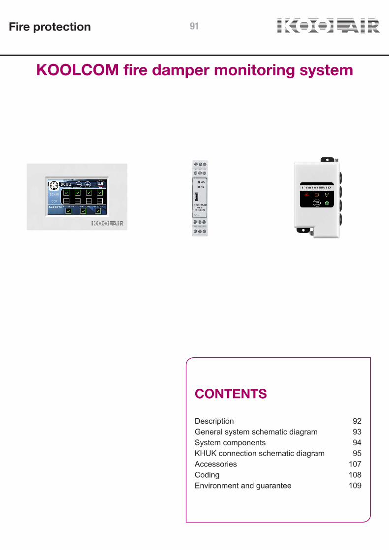
KOOLCOM fire damper monitoring system
CONTENTS
Description 92General system schematic diagram 93System components 94KHUK connection schematic diagram 95Accessories 107Coding 108Environment and guarantee 109
Fire protection 91

KOOLCOM fire damper monitoring system.
IntroductionKOOLCOM is an electronic control system for fire dampers that allows the condition and functionality of each fire damper to be periodically and automatically monitored and checked. It can also close the dampers should the fire alarm be activated.While this system is capable of being managed by a BMS (Building Management System) system, KOOLCOM can also work in Standalone mode, i.e., operate autonomously without the need for a BMS or any external maintenance personnel.
HUB Design ConceptKOOLCOM is the only system on the market whose installationis based on the HUB design concept (a central communications hub).This allows:- Control of up to 31,616 fire dampers.- Greater data communication speed (32 times faster than systems without this arrangement).- Simple alarm wiring.
Technical specifications- Control electronics for 1 to 4 fire dampers (DCU)- Control electronics for 24 V (AC and DC) and 230 V AC dampers- Autonomous or interactive with the central fire alarm system- Programmable periodic checks- Supply fan actuator, configurations for extract fans and smoke extract by means of an external contact.- MODBUS Communication. Adjustable velocity. Integratedbus terminator.- Alarm input/output. Dry contact.- Test mode for smoke detectors- Segregated graphic console.
Graphic console
Communication control unit KHUK
Fire damper control unitDCU 1CH
Fire protection92

General schematic diagram of the KOOLCOM monitoring system.
BMS
MODBUS-USB
Power
DCU1
DCU32
(Possible connections for 1 to 32 DCUs).
(Possible connections for 1 to 32 DCUs).
DCU1
DCU32
(Possible connections for 1 to 32 DCUs).
(Possible connections for 1 to 247 KHUKs).
Power
DCU1
DCU32
DCU1CH
DCU4CH
CONSOLE
Bus
ModBus
KHUK
Note: If the KHUK alarm input is connected to a fire panel, the modbus wiring between KHUK and DCUs, and between KHUK and the BMS, must be flame retardant.
Minimum cross sections for a maximum length of 100m. For longer lengths refer to standard values A.W.G. ModBus: 3 Wires. RS-485 specific cable, minimum 3 conductors + screen. Nominal impedance 100-120 ohms. AWG24 (0.2mm2 section, 0.51mm diameter, twisted).
Note: If the Alarm Input of the DCU is used, use 2 wires AWG26 (0.13mm2).
Fire protection
A - Power Connection-KHUK. 24V. 2 Wires. Observe polarity +24V and GND(-).
B - KHUK-RESET PUSH BUTTON. 24V.2 Wires. Observe polarity RESET and +24V
C - KHUK- INPUT FROM ALARM PANEL. 2 Wires. Observe polarity. +24V and ALARM.
D - KHUK-KHUK. ModBus. 3 Wires. Observe polarity A+, B- and GND.
E - KHUK-DCU. ModBus. 3 Wires. Observe polarity A+, B- and GND.
F - DCU-FIRE DAMPER. 2 Wires contacts + 2 Wire Motor.
G - DCU-SMOKE DETECTOR. 2 Wires.
H - DCU-Power 220V. 2 Wires.
I - KHUK-CONSOLE. 2 Wires. No polarity.
J - KHUK-BMS. ModBus.
K - DCU-GATE. 3 wires + 2 wires Motor.
AWG20 (0.5mm2).
AWG26 (0.13mm2).
AWG26 (0.13mm2).
0.2mm2.
0.2mm2.
Contacts AWG206 (0.13mm2)/ Motor AWG20 (0.5mm2).
AWG20 (0.5mm2).
AWG20 (0.5mm2).
AWG20 (0.5mm2).
0.2mm2.
Contacts AWG206 (0.13mm2) / Motor AWG20 (0.5mm2).
93

System components.Damper Control Unit (DCU 1CH)
DAMPER CONTROL UNIT 1 CHANNEL (DCU 1CH)DCU 1CH (Damper Control Unit, 1 Channel) are devices used to send commands and supervise motorised fire dampers, which by means of commands sent through the ModBus allow them to be automated and controlled.
They are integrated in the KOOLCOM fire damper control and supervision system. This system is completed with KHUK units (KoolCom Hub Unit KoolAir), which allow DCUs (1CH or 4CH) to be grouped in sets of 32 units, and connects the colour, touch screen consoles.
Each DCU 1CH has:
• 1 input for a conventional smoke detector (zone). • 1 output for fire damper in two available formats: • Direct connection for Belimo motors. • Universal motor connection. • 1 power input. • 1 ModBus connection. • Models: • 24V (AC/DC) - 100-DCK300: For 24V fire damper motor. • 230V AC - 100-DCK400: For 230V power supply damper motor.
The DCU contains the control electronics for the different fire dampers. KOOLCOM offers two models which allow either 1, or up to 4 dampers to be controlled by the same device.
Materials:− Casing: ABS (-40°C | 100°C).− Cable inlet: Nylon 6/6 and TPE.
Waterproofing:− Box: IP 54 − Cable inlet: IP 67/68
Fire protection94

Specifications (DCU 1CH)
Fire protection
• Maximum load on the damper motor output:
24V (AC/DC) model: 3A 230V AC model: 0.5A
• Maximum load in the detection zone: 100mA
• Maximum power consumption (without detector or damper):
24V (AC/DC) model: 100mA@24V 0.72W 230V AC model: 70mA@230V 0.88W
• Protected against short circuits and ESDs at zone connections, fire damper contacts, and ModBus.
• MODBUS:
- Device type: Slave - ModBus implementation: RTU on RS-485 - Maximum number of DCUs (without repeater): 32 - Default configuration: 9600bps 8E1 - Bus data transfer speed can be configured both on the PCB and via ModBus. - Integrated termination in PCB, can be activated by jumper. - Typical response time: <10 ms.
• Installer push-button on the front panel to: - Perform tests and set up from the front panel. - Reset alarms from the DCU itself: a laptop is not required to reset alarms if the operator is present at the DCU.
• Zone Connection: - Protected against short circuits and ESDs. - Monitored: If there is a wiring failure or the detector is disassembled, monitoring allows the problem to be detected and highlighted. - Most smoke detectors are supported, including both those that are self-limiting and those that need current to be limited in the control panel. - Automatic detection in the zone: it is not necessary to place a resistance at the terminals or to simulate a fault if the zone is not in use. - Smoke detector test mode: allows smoke detectors to be tested without the DCU triggering the fire alarms.
• Automatic fire damper testing with programmable test intervals.
• Automatic detection of fire damper and zone: it is not necessary to bypass the damper or simulate a fault if the zone is not in use.
• Clearly indicated connections next to each connector.
95

Damper Control Unit 1 channel (DCU 1CH)
The universal damper connection is a 5-wire connection: o Contacts: - S4+S1: can be connected inside the damper. - S2 and S6: Are the normally open contacts of the matching limit switches. o Motor: - COM: common, negative (or neutral in DCU 230V) - MOT: positive (or phase in DCU 230V)
MOT: normally not used, it is the same signal as MOT but with inverse logic.
The output connections to the damper motor are not dry contacts, but are already powered to supply the voltage needed to power the motor: 24V o 230V, as per the DCU model.
Binary ModBus address
ModBus termination activation
Default load
values
Input24 AC/DC
Smoke detector
connector
ConnectionModBus
Cable tie 230v Input
230v AC
Direct connection
Belimo / Siemens
Universal connection
Mot
orC
onta
cts
Fire protection96

Damper Control Unit 1 channel connection (DCU 1CH): two versions (24V / 230V)
Power
24V
100-DCK300 - 24V:
100-DCK400 - 230V:
Power
220V
ModBus IN
ModBus OUT
KHUK
DCUs
DETECTOR
Contacts Motor
DAMPER
Power supply 230V (cable tie is essential) or 24V. 2 wires.ModBus. 3 wires.
2 Wires.Contacts 3 wires + motor supply 2 wires.
Fire protection 97

System componentsDamper Control Unit 4 channel (DCU 4CH)
DCU 4CH (Damper Control Unit, 4 Channel) are devices used to send commands and supervise up to 4 motor-driven fire dampers and 4 smoke detectors, which, by means of commands sent through the ModBus, allow them to be automated and controlled
They are integrated in the KOOLCOM system for controlling and supervising motor-driven fire dampers and four smoke detectors (zones). This system is completed with KHUK units (KoolCom Hub Unit KoolAir), which allow DCUs to be grouped (1CH or 4CH) in sets of 32 units, in addition to connecting the colour, touch screen consoles.
Each DCU 4CH has:
• 4 inputs for a conventional smoke detector. • 4 outputs for fire dampers. Direct connection from motors. • 1 power input. • 1 ModBus connection. • 24V (AC/DC) and 230V AC models • Damper test button • Dry contact for external alarm input • Dry contact for supply/extract fan • Dry contact indicating alarm detected • Visual indication of the status of all the elements by means of LEDs on the board
Fire protection98

Specifications (DCU 4CH)
Fire protection
• Maximum joint load on the damper motor outputs:
24V (AC/DC) model: 3A 230V AC model: 0.5A
• Maximum load in the detection zone: 100mA per zone / 300 mA combined
• Maximum consumption (without detector or damper):
24V (AC/DC) model: 100mA@24V DC 230V AC model: 70mA@230V AC
• Auxiliary Relays (FAN AND ALARM):
24V (AC/DC) model: 5 A@24V DC 230V AC model: 5 A@230V AC (for resistive loads)
• Protected against short circuits and ESDs at zone connections, fire damper contacts and ModBus.
• MODBUS:
- Device type: Slave - ModBus implementation: RTU on RS-485 - Maximum number of DCUs (without repeater): 32 - Default configuration: 9600bps 8E1 - Bus data transfer speed can be configured both on the PCB and via ModBus. - Termination integrated in internal PCB, can be activated by jumper. - Typical response time: <10 ms.
• Installer push-button on the panel to: - Perform tests and set up. - Reset alarms from the DCU itself: a laptop is not required to reset alarms if the operator is at the DCU.
• Zone Connection: - Protected against short circuits and ESDs. - Monitored: If the wiring fails or the detector is disassembled, monitoring allows problems to be detected and highlighted. - Most smoke detectors are supported, including both those that are self-limiting and those that need current to be limited in the control panel. - Automatic detection in the zone: it is not necessary to place a resistance at the terminals or to simulate a fault if the zone is not in use. - Smoke detector test mode: allows smoke detectors to be tested without the DCU activating the fire alarms.
• Automatic fire damper testing with programmable test periods.
• Automatic detection of dampers and zones: it is not necessary to bridge or to simulate a fault if the zone is not in use.
99
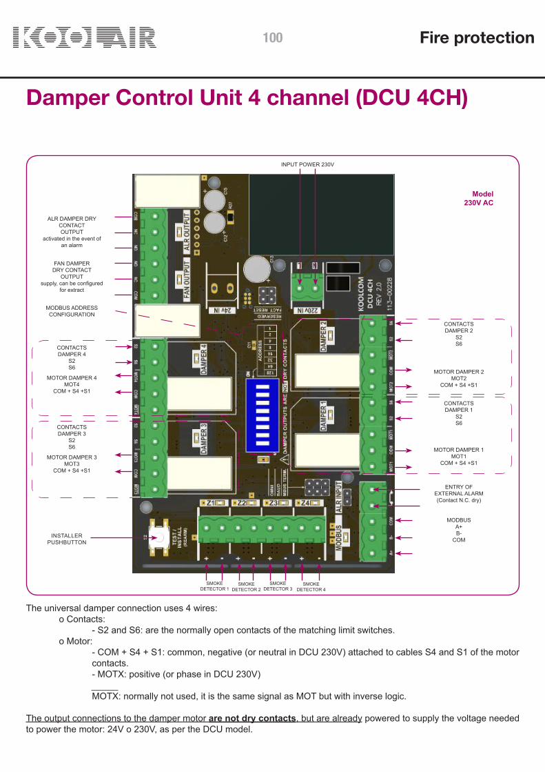
Damper Control Unit 4 channel (DCU 4CH)
INSTALLER PUSH BUTTON
INPUT POWER 230V
CONTACTSDAMPER 2
S2S6
Model230V AC
CONTACTSDAMPER 1
S2S6
CONTACTSDAMPER 3
S2S6
CONTACTSDAMPER 4
S2S6
ALR DAMPER DRY CONTACT OUTPUT
activated in the event of an alarm
MODBUS ADDRESS CONFIGURATION
FAN DAMPER DRY CONTACT
OUTPUTsupply, can be configured
for extract
SMOKEDETECTOR 4
SMOKEDETECTOR 3
SMOKEDETECTOR 2
SMOKEDETECTOR 1
MOTOR DAMPER 2MOT2
COM + S4 +S1
MOTOR DAMPER 1MOT1
COM + S4 +S1MOTOR DAMPER 3
MOT3COM + S4 +S1
MOTOR DAMPER 4MOT4
COM + S4 +S1
Fire protection
The universal damper connection uses 4 wires: o Contacts: - S2 and S6: are the normally open contacts of the matching limit switches. o Motor: - COM + S4 + S1: common, negative (or neutral in DCU 230V) attached to cables S4 and S1 of the motor contacts. - MOTX: positive (or phase in DCU 230V)
MOTX: normally not used, it is the same signal as MOT but with inverse logic.
The output connections to the damper motor are not dry contacts, but are already powered to supply the voltage needed to power the motor: 24V o 230V, as per the DCU model.
MODBUSA+B-
COM
ENTRY OFEXTERNAL ALARM(Contact N.C. dry)
100

Damper Control Unit 1 channel connection (DCU 4CH): two models (24V / 230V)
100-DCK200 - 230V AC:100-DCK100 - 24V AC/DC:Power230V
Power24V
Alarm inputExterior
ModBusIN
ModBus OUT
DCUs
Contacts
ContactsContacts
Contacts
Motor
MotorMotor
Motor
DETECTORS
DAMPERS DAMPERS
Z1 Z2 Z3 Z4
C1
C2
C3
C4
230V AC or 24V AC/DC supply. 2 wires. ModBus. 3 wires.2 wires.2 wires.2 wires contacts (S2, S6) + 2 wires motor supply (COM+S4+S1), MOTx.
Fire protection 101

System components.KHUK (HUB)
The KHUK is a Modbus hub device that occupies a single address, allows up to 128 fire dampers and 128 smoke detectors (32 DCU-4CH units) to be managed.
Each KHUK has:
- 1 connection to the Koolcom console. - Direct connection to fire panel: • Alarm activation input. • Alarm reset input. • NO alarm relay output (Max 8Amp). - 1 24V DC power input. - Maximum consumption: 100–UCK000: 125mA@24v - 1 ModBus connection on RS485 for DCUs. - 1 ModBus connection on RS485 for BMS. - ModBus:
Type of device going to DCUs: Master Type of device going to the BMS: Slave ModBus implementation: ModBus RTU on RS-485 Maximum number of DCUs: 32 Default configuration: 9600bps 8E1
The KHUK is always powered by a 24V DC power supply.
Fire protection102

System components. Graphic console
The KOOLCOM graphic console allows monitoring and control of DCUs connected to the associated KHUK,facilitating the monitoring and control of fire dampers and smoke detectors (zones).
The console allows information on the overall status of the system and each connected DCU to be displayed, as well asthe basic parameters to be configured and managed. (* Only available in installations that include KHUKs).
KOOLCOM Graphic Console with 3.2” display. Surface mounted version. Specific flush mounted box availablefor flush mounting.
CHARACTERISTICS:
- Surface mounted or flush (optional) - Powered from the KHUK (No external power supply required). - Dimensions: 79x119x16 mm. - TFT 3.2” display. 65,536 colours. 4R resistant touch panel. - Resolution: 400x240 pixels. - Testing, control and monitoring of up to 128 fire dampers and 128 smoke detectors (32 No. DCU 4CH). - Autonomous or integrated with the central fire alarm system - Programmable periodic checks - Global and localised indication of the state of the zones (smoke detectors) and the fire dampers.
Fire protection 103

KHUK connection schematic
One KHUK has connections for up to 32 DCUs (maximum 128 dampers and 128 detectors), the wall mounted graphic console and a BMS. It can interact with the central fire alarm system with external alarms going to the KHUK and detected alarm coming from the KHUK.
CONSOLE
Power supply
FIRE PANEL N.O. ALARM OUTPUT MODBUS TO BMS
MODBUS TO THE DCU
Alarm activation
Reset alarm
MODBU-USB
1-32 DCUs
BMS
Fire protection104

KHUK AND DCUs
Three wires with polarity that connect exclusively to the DCUs. The KHUK contains the MODBUS termination. By inserting the MBUS TERM bridge into the furthest DCU, the two necessary terminations are achieved. Different DCU models (DCU-1CH and DCU-4CH) can be mixed in the same bus.
For the modbus wiring, RS-485 cable must always be used; available from various manufacturers.
DCU 32
DCU 4CH
DCU 1KHUK
DCU 1CH
ModBus to DCUs
Connect the DCUs one to another. Maximum 32 DCUs per KHUK.
The furthest DCU must haveThe MBUS TERM bridge inserted
1 - 32 DCUs
MOD-BUS TopologyDaisy Chain topology must be used wherever possible. If this is not feasible at any point, a Backbone with stubs can also be used.
In cases where backbone with stubs topology is used, the stubs should be as short as possible and never exceed 10 meters.
Fire protection 105

C RELEON RELE
KHUK and alarms
Fire Alarm and Reset Input: When the +24V from the source is received at the alarm input, the KHUK considers there to be a fire alarm external to the system (not activated by the smoke detectors). It will activate the alarm input on each DCU connected to the KHUK, resulting in the closing of all connected dampers.
N.O. Alarm Relay Output: Volt-free contacts with a maximum switching capacity of 8Amp, which are closed when any DCU informs the KHUK of the occurrence of an alarm. They are usually connected to the central fire alarm system, which awaits the closure of these contacts.
CENTRAL FIRE ALARM
N.O. AlarmOutput
KHUK
CENTRAL FIRE ALARM
KHUK
Power supply
Alarm activation
Reset alarm
Three wires with polarity that are connected to a PC that contains an available RS485 port. The third wire COM (Ref.) is the negative of the KHUK supplier (GND).
KHUK and BMS
KHUK
BMS
USB-MODBUS
Fire protection106

Accessories
This section describes the accessories that may be necessary during installation.
Cable MODBUSThis depends on the specific conditions of each installation,especially the level of electrical noise in the zones which the wiring passes through, the distance to be covered and the chosen connection speed. We recommend that RS-485-specific cable always be used.
In general the cable specifications will comply with:
- be twisted pair (or pairs) cable. - have at least three conductors + screen. - nominal impedance: 100-120 ohms - AWG24 (section 0.2mm2, diameter 0.51mm) - screened
MODBUS Extender/IsolatorOptical MODBUS Extender / Isolator. In cases with long cable runs, or even to facilitate easy fault detection in the installation, this allows the connection wiring between the KHUK and the different DCUs to be expanded and isolated.
USB-MODBUS InterfaceAllows the KOOLCOM system and a computer to be connected ifthere is no integrated RS485 port.
Fire protection 107

Accessories
CODE DESCRIPTION100-UCK000 KOOLCOM HUB100-TCK000 KOOLCOM GRAPHIC DISPLAY100-DCK100 DAMPER CONTROL UNIT KOOLCOM, 4 DAMPERS, 24V (AC/DC)100-DCK200 DAMPER CONTROL UNIT KOOLCOM, 4 DAMPERS, 230V AC100-DCK300 DAMPER CONTROL UNIT KOOLCOM, 1 DAMPER, 24V (AC/DC)100-DCK400 DAMPER CONTROL UNIT KOOLCOM, 1 DAMPER, 230V AC100-MBUS00 CABLE MODBUS TWISTED KOOLCOM, 3 CONDUCTORS+MESH100-MBUS01 KOOLCOM SYSTEM OPTICAL ISOLATOR / EXTENDOR 100-MBUS02 MODBUS INTERFACE TO KOOLCOM USB100-TCK001 KOOLCOM GRAPHIC CONSOLE BACK BOX
Graphic console back boxNon-standard back box for installations where the graphic console is to be flush mounted instead of surface mounted.
Coding
Fire protection108

Environment, guarantee and safety.
ENVIRONMENTNever dispose of this equipment together with household waste. Electrical and electronic products contain substances that can be harmful to the environment if not disposed of properly. The symbol of a crossed out rubbish bin indicates the special collection of electrical appliances, differing from other urban rubbish. For correct environmental disposal, they should be taken to specially designed collection centres at the end of their useful life. Their constituent parts are recyclable. Therefore, observe the applicable environmental protection regulations.
You must return them to your dealer if they are being replaced by another, or dispose of them at a specialised collection centre.
Violators are subject to the sanctions and measures established by the Law on environmental protection.
GUARANTEEThis product is covered by a legal guarantee; please contact your seller for more information.
KOOLCOM guarantees the products will conform to the technical specifications for a period of 2 years, including parts and labour, from the date of purchase included on the purchase document. The user can put the guarantee into effect at the distributor or point of sale or by calling the customer service number. The nonconforming part or product will be repaired or replaced by an equivalent piece or product at no cost to the customer. Any part or product changed becomes the property of KOOLCOM. The remedied defect of the repaired product is guaranteed for a period of 6 months from the date of repair.
However, this guarantee does not apply in the following cases:
Installation or use that is not in accordance with the instructions given in this manual; incorrect connection or improper use of the product, in particular, with accessories not designed for the purpose; abnormal wear; failure to comply with the technical and safety standards in force in the geographical area of use; products that have received shocks or falls: products damaged by lightning, electrical overloads, heat sources or radiation, water damage, exposure to excessive humidity or any other outside cause; misuse or negligence; intervention, modification or repair by any person not approved by the manufacturer or distributor CONDITIONAL TO THE LEGAL PROVISIONS, ALL WARRANTIES DIFFERENT FROM THOSE DESCRIBED IN THIS SECTION ARE SPECIFICALLY EXCLUDED.
Fire protection 109

Fire and smoke dampers UL ApprovalFSD-B-U / FSD-A-U and FLD-S-U / FLD-S-UD
CONTENTS
Description FSD-B-U / FSD-A-U 111Construction details FSD-B-U / FSD-A-U 112Dimensions FSD-B-U / FSD-A-U 113Operation FSD-B-U / FSD-A-U 114Description FLD-S-U / FLD-S-UD 115Construction details FLD-S-U / FLD-S-UD 116Dimensions FLD-S-U / FLD-S-UD 116Operation FLD-S-U / FLD-S-UD 117Periodic inspection FLD-S-U / FLD-S-UD 118Technical data 119
Fire protection110

FSD-A-U
FSD-A-U
FSD-B-U / FSD-A-U Fire and smoke dampers.UL Approval
DescriptionThe FSD-B-U and FSD-A-U models are 3V type multi-bladefire and smoke dampers approved according to UL standards(UL555 and UL555S).
Fire dampers close automatically to prevent fire and smoke fromspreading to adjacent fire compartments through HVACventilation ductwork.
The dampers are approved to withstand fire conditions for 90minutes according to UL555 standard. The FSD-B-U modelachieves Class 1 leakage level according to UL555S at atemperature of 177 °C. The FSD-A-U model achieves Class 3leakage level according to UL555S at a temperature of 177 °C.
The FSD-B-U model fire damper incorporateselastomeric airtight seals along the edges of the closing blades.
The casings or frames of the dampers are manufactured withreinforced corners. Where height H <425 mm, low profile linesare used at the top and bottom of the frame. The blades arereinforced with 3 lengthways structural sections called “Vee’s” toprovide them with greater rigidity and resistance.
Silicone sealant is applied to the joint between the frame and itsenclosure to prevent any air or smoke leakage.
An inspection hatch is required in the ductwork adjacent to the damper to facilitate periodic inspection and maintenance.
The FSD-B-U / FSD-A-U models are installed vertically with theblades in a horizontal position, regardless of the direction of thehorizontal air flow.
Fire protection 111
FSD-B-U / FSD-A-U Fire and smoke dampers.UL ApprovalConstruction details:
Maximum levels of operation:
Design and manufacture details FSD-B-U / FSD-A-U dampers
Damper frame or casing material Galvanised steel
Damper frame or casing thickness 1.6 mm
Damper frame or casing profile type Omega profile – 123 mm thick
Closing blade material Galvanised steel
Closing blade thickness 1.6 mm
Closing blade type Type triple V
Sealing. Airtightness Integrated gasket in the casing or frame
Damper shaft bearings Bronze casing pressed into the casing or frame
Damper shaft material Sheet steel
Airtight seal in the interior of the damper Stainless steel - metal flexible under compression
Airtight seals on blades Silicone (FSD-B-U model)
Thermal actuator + opening andclosing servomotor
Thermal actuator (thermoelectric fusible link) that operates attemperatures above 74 ºC.
Electric servomotor 24V, with auxiliary changer (230 V option)
Damper exterior enclosure Minimum 432 mm, thickness 1 mm. Galvanised steel.
Levels of operation:
Description FSD-A-U/FSD-B-U models
UL 555S leak classification Class 1 (FSD-B-U) and Class 3 (FSD-A-U)
UL 555 fire resistance classification 90 minutes (1.5 h)
Maximum velocity 10 m/s
Maximum pressure 1000 Pa
Fire protection112

H / L 200 300 400 500 600 700 800 900 1000 1100 1200 1300 1400 1500 1600 1700 1800
150
300
450
600
750
900
1050
1200
H / L 200 300 400 500 600 700 800 900 1000 1100 1200 1300 1400 1500 1600 1700 1800
150
300
450
600
750
900
1050
1200
FSD-B-U / FSD-A-U Fire and smoke dampers.UL ApprovalDimensions:
FSD-A-U
FSD-B-U
MIN. 432 mm
MIN. 432 mm
L
L
HH
Dimensions
Simple selection (L x H) Multiple selection (L x H)
152 x 203 mm (minimum dimension) 1828 x 1371 mm (maximum dimension)
914 x 1220 mm (maximum dimension)
Fire protection 113
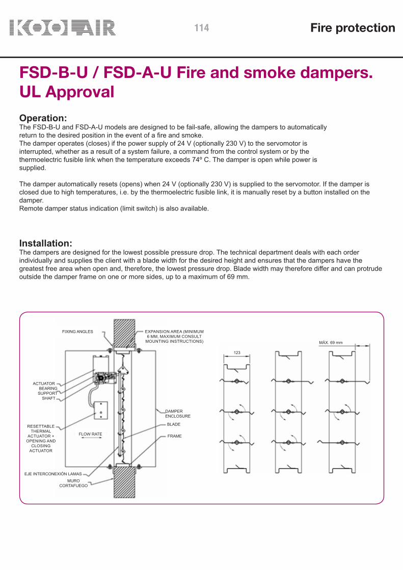
FSD-B-U / FSD-A-U Fire and smoke dampers.UL ApprovalOperation:The FSD-B-U and FSD-A-U models are designed to be fail-safe, allowing the dampers to automaticallyreturn to the desired position in the event of a fire and smoke.The damper operates (closes) if the power supply of 24 V (optionally 230 V) to the servomotor isinterrupted, whether as a result of a system failure, a command from the control system or by thethermoelectric fusible link when the temperature exceeds 74º C. The damper is open while power issupplied.
The damper automatically resets (opens) when 24 V (optionally 230 V) is supplied to the servomotor. If the damper isclosed due to high temperatures, i.e. by the thermoelectric fusible link, it is manually reset by a button installed on thedamper.Remote damper status indication (limit switch) is also available.
Installation:The dampers are designed for the lowest possible pressure drop. The technical department deals with each orderindividually and supplies the client with a blade width for the desired height and ensures that the dampers have thegreatest free area when open and, therefore, the lowest pressure drop. Blade width may therefore differ and can protrudeoutside the damper frame on one or more sides, up to a maximum of 69 mm.
MÁX. 69 mm
123
FLOW RATE
EJE INTERCONEXIÓN LAMASMURO
CORTAFUEGO
DAMPERENCLOSURE
ACTUATORBEARING
SUPPORTSHAFT
FRAME
BLADE
FIXING ANGLES EXPANSION AREA (MINIMUM6 MM, MAXIMUM CONSULT
MOUNTING INSTRUCTIONS)
RESETTABLETHERMAL
ACTUATOR +OPENING AND
CLOSINGACTUATOR
Fire protection114
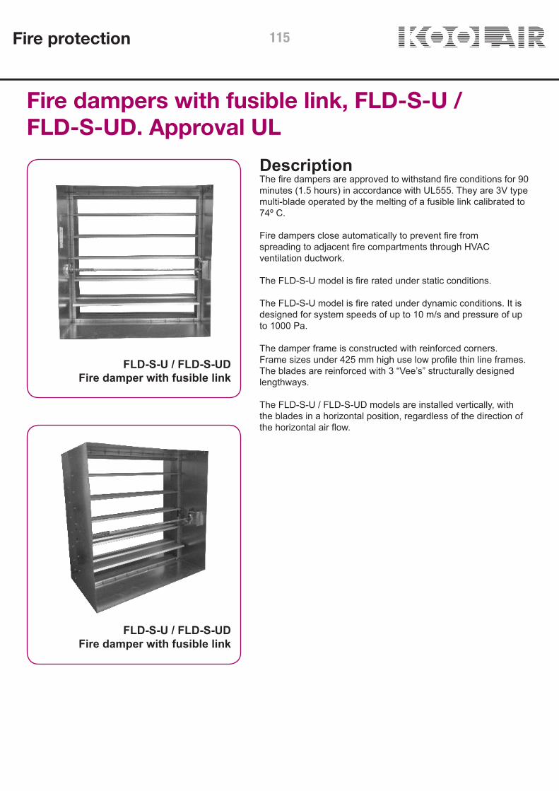
Fire dampers with fusible link, FLD-S-U /FLD-S-UD. Approval UL
DescriptionThe fire dampers are approved to withstand fire conditions for 90minutes (1.5 hours) in accordance with UL555. They are 3V typemulti-blade operated by the melting of a fusible link calibrated to74º C.
Fire dampers close automatically to prevent fire fromspreading to adjacent fire compartments through HVACventilation ductwork.
The FLD-S-U model is fire rated under static conditions.
The FLD-S-U model is fire rated under dynamic conditions. It isdesigned for system speeds of up to 10 m/s and pressure of upto 1000 Pa.
The damper frame is constructed with reinforced corners.Frame sizes under 425 mm high use low profile thin line frames.The blades are reinforced with 3 “Vee’s” structurally designedlengthways.
The FLD-S-U / FLD-S-UD models are installed vertically, withthe blades in a horizontal position, regardless of the direction ofthe horizontal air flow.
FLD-S-U / FLD-S-UDFire damper with fusible link
FLD-S-U / FLD-S-UDFire damper with fusible link
Fire protection 115
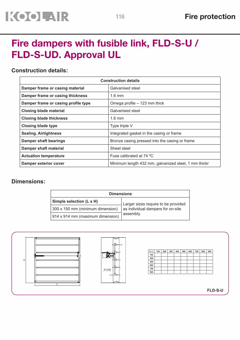
H / L 150 200 300 400 500 600 700 800 900150300450600750900
Fire dampers with fusible link, FLD-S-U /FLD-S-UD. Approval ULConstruction details:
Dimensions:
Construction details
Damper frame or casing material Galvanised steel
Damper frame or casing thickness 1.6 mm
Damper frame or casing profile type Omega profile – 123 mm thick
Closing blade material Galvanised steel
Closing blade thickness 1.6 mm
Closing blade type Type triple V
Sealing. Airtightness Integrated gasket in the casing or frame
Damper shaft bearings Bronze casing pressed into the casing or frame
Damper shaft material Sheet steel
Actuation temperature Fuse calibrated at 74 ºC
Damper exterior cover Minimum length 432 mm, galvanized steel, 1 mm thickr
Dimensions
Simple selection (L x H) Larger sizes require to be providedas individual dampers for on-siteassembly.
300 x 150 mm (minimum dimension)
914 x 914 mm (maximum dimension)
FLD-S-U
FLOW
L
H
Fire protection116
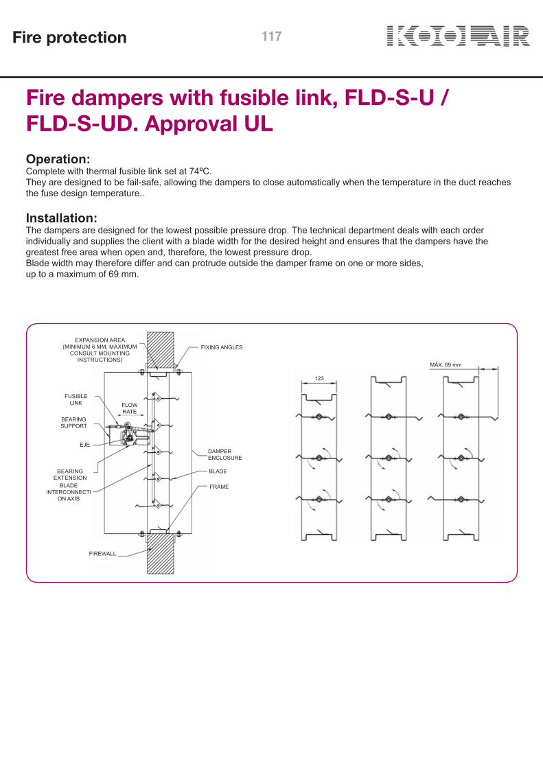
Operation:Complete with thermal fusible link set at 74ºC.They are designed to be fail-safe, allowing the dampers to close automatically when the temperature in the duct reaches the fuse design temperature..
Fire dampers with fusible link, FLD-S-U /FLD-S-UD. Approval UL
Installation:The dampers are designed for the lowest possible pressure drop. The technical department deals with each orderindividually and supplies the client with a blade width for the desired height and ensures that the dampers have thegreatest free area when open and, therefore, the lowest pressure drop.Blade width may therefore differ and can protrude outside the damper frame on one or more sides,up to a maximum of 69 mm.
MÁX. 69 mm
123
FLOWRATE
BLADEINTERCONNECTI
ON AXIS
FIREWALL
DAMPERENCLOSURE
FUSIBLELINK
BEARINGSUPPORT
EJE
FRAME
BLADE
FIXING ANGLESEXPANSION AREA
(MINIMUM 6 MM, MAXIMUMCONSULT MOUNTING
INSTRUCTIONS)
BEARINGEXTENSION
Fire protection 117

Fire dampers with fusible link, FLD-S-U /FLD-S-UD. Approval ULPeriodic inspection, testing and maintenance
The basic inspection, testing and maintenance procedures are described below.
Inspection:Regular inspection, testing and maintenance are essential to ensure that the fire and smoke dampers in an installationoperate as intended. Inspection and maintenance should include periodic testing of all equipment, including dampers,fans, operating devices, controls, etc. Standards such as NFPA 92A, NFPA 80, NFPA105 and local codes must beconsulted for guidance with respect to the intervals of damper inspection, testing, and maintenance. The intervals ofinspection, testing and maintenance vary widely depending on the system’s length of operation, the condition of the airand other factors.
Maintenance:• Check the electric servomotor and tighten the coupling if necessary.• Check the damper blades and other parts as necessary.• Lubricate the latch, bearings and other moving parts with a silicone lubricant. Petroleum-based products should not beused as they may accumulate dust.• Activate the damper using the electric servomotor.• Check the blades to make sure they close and reopen completely.• Check the damper to make sure it is perpendicular and the blade channel is not obstructed.
Test:• Use a moderate heat source and heat the thermal disk inside the damper.• Once the required temperature has been reached, the power supply to the servomotor will be switched off and themotor spring will close the damper blades.• The damper must be tested under normal air flow conditions.
Fire protection118

150
400
500
1000
750
4500
1500
2000
3000
150
400
500
1000
750
4500
1500
2000
3000
0,01
0,10
1,00
1 10
A L(m
2 )
Veff (m/s)
Q (m
3 /h)
1,040
0,200
3025
4045
50
35
0,540 55
60
1
10
100
1000
1 10
∆P
(Pa)
Veff (m/s)
kp
LwA [dB(A)]
2 3 4 5 6 7 8 9
0,54
1,80
Fire damper FSD-B-U / FSD-A-U FLD-S-U /FLD-S-UD. Technical dataSelection chart FSD-B-U / FSD-A-U FLD-S-U / FLD-S-UD
Selection example:For the given duct dimensions and technical data, we select a 1200 x 200 mm FSD-B-U damper. We use the table on theprevious page to find the following data: AL = 0,24 m2 kp = 1,8 kdB(A)= -2The technical data to achieve a flow rate of 3500 m3/h is required. Referring to the diagram above using this flow rate and the area o 0,24 m2, we obtain a Veff of 4 m/s. With this veocityand taking into account the value of kp, we obtain:Differential pressure: 30 PaSound pressure level: 45 dB(A)Applying LwA- dB(A) = 45+ (-2) = 43 dB(A)
Fire protection 119
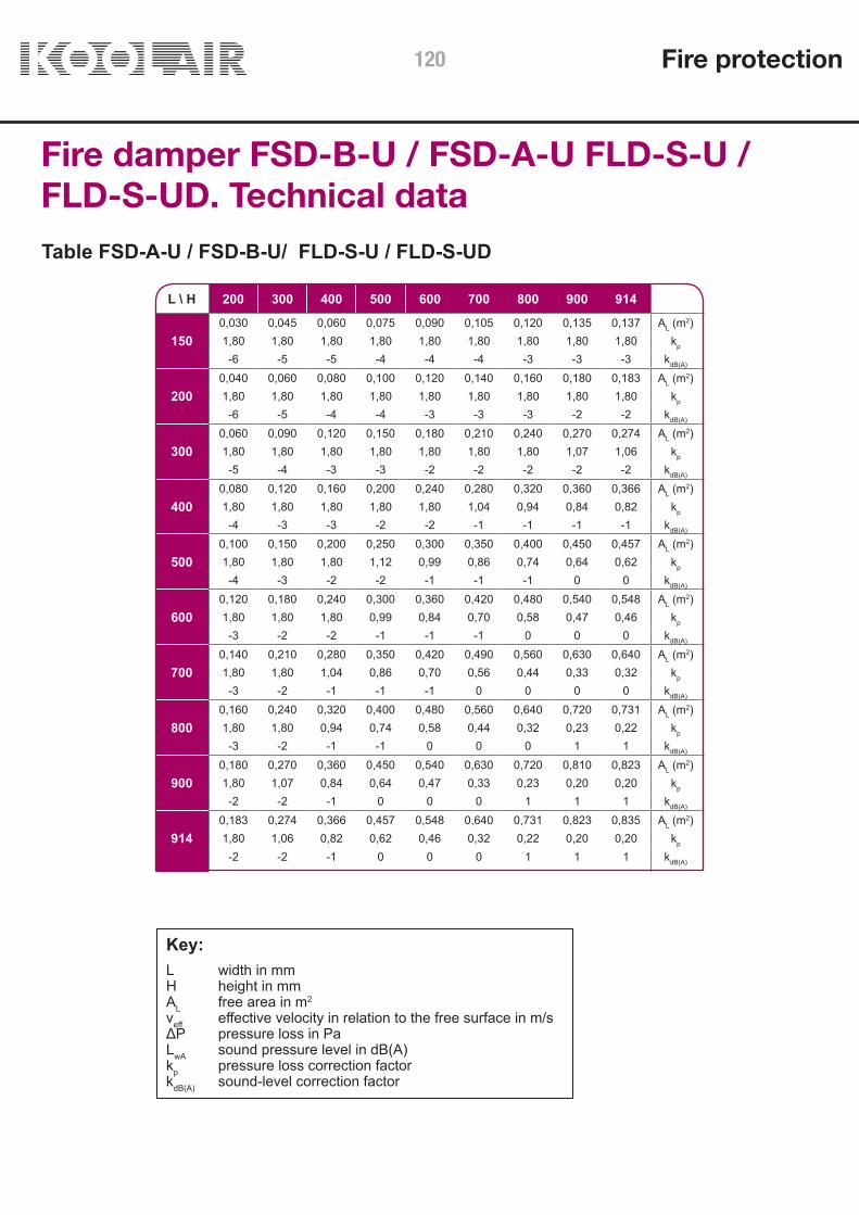
L \ H 200 300 400 500 600 700 800 900 914
1500,030 0,045 0,060 0,075 0,090 0,105 0,120 0,135 0,137 AL (m2)1,80 1,80 1,80 1,80 1,80 1,80 1,80 1,80 1,80 kp
-6 -5 -5 -4 -4 -4 -3 -3 -3 kdB(A)
2000,040 0,060 0,080 0,100 0,120 0,140 0,160 0,180 0,183 AL (m2)1,80 1,80 1,80 1,80 1,80 1,80 1,80 1,80 1,80 kp
-6 -5 -4 -4 -3 -3 -3 -2 -2 kdB(A)
3000,060 0,090 0,120 0,150 0,180 0,210 0,240 0,270 0,274 AL (m2)1,80 1,80 1,80 1,80 1,80 1,80 1,80 1,07 1,06 kp
-5 -4 -3 -3 -2 -2 -2 -2 -2 kdB(A)
4000,080 0,120 0,160 0,200 0,240 0,280 0,320 0,360 0,366 AL (m2)1,80 1,80 1,80 1,80 1,80 1,04 0,94 0,84 0,82 kp
-4 -3 -3 -2 -2 -1 -1 -1 -1 kdB(A)
5000,100 0,150 0,200 0,250 0,300 0,350 0,400 0,450 0,457 AL (m2)1,80 1,80 1,80 1,12 0,99 0,86 0,74 0,64 0,62 kp
-4 -3 -2 -2 -1 -1 -1 0 0 kdB(A)
6000,120 0,180 0,240 0,300 0,360 0,420 0,480 0,540 0,548 AL (m2)1,80 1,80 1,80 0,99 0,84 0,70 0,58 0,47 0,46 kp
-3 -2 -2 -1 -1 -1 0 0 0 kdB(A)
7000,140 0,210 0,280 0,350 0,420 0,490 0,560 0,630 0,640 AL (m2)1,80 1,80 1,04 0,86 0,70 0,56 0,44 0,33 0,32 kp
-3 -2 -1 -1 -1 0 0 0 0 kdB(A)
8000,160 0,240 0,320 0,400 0,480 0,560 0,640 0,720 0,731 AL (m2)1,80 1,80 0,94 0,74 0,58 0,44 0,32 0,23 0,22 kp
-3 -2 -1 -1 0 0 0 1 1 kdB(A)
9000,180 0,270 0,360 0,450 0,540 0,630 0,720 0,810 0,823 AL (m2)1,80 1,07 0,84 0,64 0,47 0,33 0,23 0,20 0,20 kp
-2 -2 -1 0 0 0 1 1 1 kdB(A)
9140,183 0,274 0,366 0,457 0,548 0,640 0,731 0,823 0,835 AL (m2)1,80 1,06 0,82 0,62 0,46 0,32 0,22 0,20 0,20 kp
-2 -2 -1 0 0 0 1 1 1 kdB(A)
Table FSD-A-U / FSD-B-U/ FLD-S-U / FLD-S-UD
Key:L width in mmH height in mmAL free area in m2
veff effective velocity in relation to the free surface in m/sΔP pressure loss in PaLwA sound pressure level in dB(A)kp pressure loss correction factorkdB(A) sound-level correction factor
Fire damper FSD-B-U / FSD-A-U FLD-S-U /FLD-S-UD. Technical data
Fire protection120

H \ L 200 300 400 500 600 700 800 900 914
10000,20 0,30 0,40 0,50 0,60 0,70 0,80 0,90 0,91 AL (m2)1,80 0,99 0,74 0,54 0,37 0,25 0,20 0,20 0,20 kp
-2 -1 -1 0 0 1 1 1 1 kdB(A)
11000,22 0,33 0,44 0,55 0,66 0,77 0,88 0,99 1,01 AL (m2)1,80 0,91 0,66 0,45 0,29 0,20 0,20 0,20 0,20 kp
-2 -1 0 0 0 1 1 1 1 kdB(A)
12000,24 0,36 0,48 0,60 0,72 0,84 0,96 1,08 1,10 AL (m2)1,80 0,84 0,58 0,37 0,23 0,20 0,20 0,20 0,20 kp
-2 -1 0 0 1 1 1 1 2 kdB(A)
13000,26 0,39 0,52 0,65 0,78 0,91 1,04 1,17 1,19 AL (m2)1,09 0,77 0,50 0,31 0,20 0,20 0,20 0,20 0,20 kp
-2 -1 -1 0 0 1 1 1 1 kdB(A)
13710,274 0,411 0,548 0,686 0,823 0,960 1,097 1,234 1,253 AL (m2)1,06 0,72 0,46 0,26 0,20 0,20 0,20 0,20 0,20 kp
-2 -1 -1 0 0 1 1 1 1 kdB(A)
Table FSD-A-U / FSD-B-U
Fire dampers FSD-B-U / FSD-A-U FLD-S-U /FLD-S-UD. Technical data
Fire protection 121

L \ H 1000 1100 1200 1300 1400 1500 1600 1700 1800 1828
1500,150 0,165 0,180 0,195 0,210 0,225 0,240 0,255 0,270 0,274 AL (m2)1,80 1,80 1,80 1,80 1,80 1,80 1,80 1,11 1,07 1,06 kp
-3 -3 -2 -2 -2 -2 -2 -2 -2 -2 kdB(A)
2000,200 0,220 0,240 0,260 0,280 0,300 0,320 0,340 0,360 0,366 AL (m2)1,80 1,80 1,80 1,09 1,04 0,99 0,94 0,88 0,84 0,82 kp
-2 -2 -2 -2 -1 -1 -1 -1 -1 -1 kdB(A)
3000,300 0,330 0,360 0,390 0,420 0,450 0,480 0,510 0,540 0,548 AL (m2)0,99 0,91 0,84 0,77 0,70 0,64 0,58 0,52 0,47 0,46 kp
-1 -1 -1 -1 -1 0 0 0 0 0 kdB(A)
4000,400 0,440 0,480 0,520 0,560 0,600 0,640 0,680 0,720 0,731 AL (m2)0,74 0,66 0,58 0,50 0,44 0,37 0,32 0,27 0,23 0,22 kp
-1 0 0 0 0 0 0 0 1 1 kdB(A)
5000,500 0,550 0,600 0,650 0,700 0,750 0,800 0,850 0,900 0,914 AL (m2)0,54 0,45 0,37 0,31 0,25 0,20 0,20 0,20 0,20 0,20 kp
0 0 0 0 1 1 1 1 1 1 kdB(A)
6000,600 0,660 0,720 0,780 0,840 0,900 0,960 1,020 1,080 1,097 AL (m2)0,37 0,29 0,23 0,20 0,20 0,20 0,20 0,20 0,20 0,20 kp
0 0 1 1 1 1 1 1 1 2 kdB(A)
7000,700 0,770 0,840 0,910 0,980 1,050 1,120 1,190 1,260 1,280 AL (m2)0,25 0,20 0,20 0,20 0,20 0,20 0,20 0,20 0,20 0,20 kp
1 1 1 1 1 1 2 2 2 2 kdB(A)
8000,800 0,880 0,960 1,040 1,120 1,200 1,280 1,360 1,440 1,462 AL (m2)0,20 0,20 0,20 0,20 0,20 0,20 0,20 0,20 0,20 0,20 kp
1 1 1 1 2 2 2 2 2 2 kdB(A)
9000,900 0,990 1,080 1,170 1,260 1,350 1,440 1,530 1,620 1,645 AL (m2)0,20 0,20 0,20 0,20 0,20 0,20 0,20 0,20 0,20 0,20 kp
1 1 1 2 2 2 2 2 2 2 kdB(A)
9140,914 1,005 1,097 1,188 1,280 1,371 1,462 1,554 1,645 1,671 AL (m2)0,20 0,20 0,20 0,20 0,20 0,20 0,20 0,20 0,20 0,20 kp
1 1 2 2 2 2 2 2 2 2 kdB(A)
10001,00 1,10 1,20 1,30 1,40 1,50 1,60 1,70 1,80 1,83 AL (m2)0,20 0,20 0,20 0,20 0,20 0,20 0,20 0,20 0,20 0,20 kp
1 2 2 2 2 2 2 2 3 3 kdB(A)
11001,10 1,21 1,32 1,43 1,54 1,65 1,76 1,87 1,98 2,01 AL (m2)0,20 0,20 0,20 0,20 0,20 0,20 0,20 0,20 0,20 0,20 kp
2 2 2 2 2 2 3 3 3 3 kdB(A)
12001,20 1,32 1,44 1,56 1,68 1,80 1,92 2,04 2,16 2,19 AL (m2)0,20 0,20 0,20 0,20 0,20 0,20 0,20 0,20 0,20 0,20 kp
2 2 2 2 2 3 3 3 3 3 kdB(A)
13001,30 1,43 1,56 1,69 1,82 1,95 2,08 2,21 2,34 2,38 AL (m2)0,20 0,20 0,20 0,20 0,20 0,20 0,20 0,20 0,20 0,20 kp
1 2 2 2 2 2 2 2 3 3 kdB(A)
13711,371 1,508 1,645 1,782 1,919 2,057 2,194 2,331 2,468 2,506 AL (m2)0,20 0,20 0,20 0,20 0,20 0,20 0,20 0,20 0,20 0,20 kp
1 2 2 2 2 2 2 2 3 3 kdB(A)
Table FLD-S-U / FLD-S-UD
Fire dampers FSD-B-U / FSD-A-U FLD-S-U /FLD-S-UD. Technical data
Fire protection122
THIS CATALOG IS INTELLECTUAL PROPERTY.The partial or total reproduction of its contents is forbidden without the express and authoritative authorisation of KOOLAIR, S.L.
CEN-PCI-0119-00
Fire protection 123

KOOLAIR, S.L.
Calle Urano, 26Poligono industrial nº 2 – La Fuensanta 28936 Móstoles - Madrid - (España) Tel: +34 91 645 00 33Fax: +34 91 645 69 62e-mail: [email protected]
www.koolair.com