
Fire: EN 13501 – the European Standard · 3 Timber beams Wooden floorboards with tongue and...
16
Fire: EN 13501 – the European Standard Resistance to fire OWAlifetime | OWAconsult
Transcript of Fire: EN 13501 – the European Standard · 3 Timber beams Wooden floorboards with tongue and...
Fire: EN 13501 – the European Standard
Resistance to fireOWAlifetime | OWAconsult

2
Additional requirements European classaccording to EN 13501-1
No smoke No burning droplets falling/dripping
3 3 A13 3 A2-s1,d03 3 B-s1,d0 | C-s1,d0
3 A2-s2,d0 | A2-s3,d0B, C-s2,d0 | B, C-s3,d0
3 A2-s1,d1 | A2-s1,d2B, C-s1,d1 | B, C-s1,d2
A2-s3,d2 | B-s3,d23 3 D-s1,d0
3 D-s2,d0 |D-s3,d0E | E-d2 | F
3 D-s1,d2 | D-s2,d2 | D-s3,d2
Resistance to fire class EN 13501-2
Resistance to fire duration in minutes
REI 30 ≥ 30REI 60 ≥ 60REI 90 ≥ 90REI 120 ≥ 120REI 180 ≥ 180
The European StandardsThe harmonized European Fire Standards are a set of test standards that have been accepted by all countries within the European Economic Community. This allows manufacturers to produce or import products that have been tested to a common standard without the need to test in each member state. Testing to these standards is now accepted in all EEC countries.
Compliance with the European Standards and regulations is mandatory.
All certified European test laboratories (“Notified Bodies”) who are listed with EOTA (European Organisation for Technical Approval) may perform these tests and issue the corresponding test reports (ITT – Initial Type Testing). In addition there may be national test or building regulation requirements that may need to be observed.
The Declaration of Performance (DoP) and the “KIT” CE label are the two main documents that will normally be required by local authority officers to show that the intended ceiling system will meet the specified performance level. The use of components other than those supplied by OWA will prevent the issuing of a KIT label.
Resistance to fire
For European categorisation, a reaction to fire classification is always given separately.
Structural elements based on EN 13501-2 encompass the whole structural element and not just the suspended ceiling. This may consist of the roof and the suspended ceiling or the structural floor and suspended ceiling. The entire element should resist the impact of fire on its structural ability for as long as possible. The length of time this can be maintained is the fire resistance duration and will classify it in one of the classes shown.
Reaction to fire If a fire is able to find sufficient flammable materials it will quickly spread through an area. It is therefore crucial to use materials of limited combustibility on key surfaces within a room, such as ceilings and walls. The use of such materials can dramatically reduce the speed flames spread through an area as well as minimise their contribution to the fire.
The European Standard EN 13501-1: Reaction to fire provides a number of performance criteria to measure the fire characteristics of building products. These cover spread of flame and contribution to fire as well the generation of smoke and the production of burning droplets. The table below provides an overview of the available classifications.
The additional designations are:
Smoke | s1, s2, s3 s1 = little or no smoke generation s2 = medium smoke generation s3 = heavy smoke generation
Burning droplets | d0, d1, d2 d0 = no droplets within 600 seconds d1 = droplet form within 600 seconds but do not burn for more than
10 secondsd2 = not as d0 or d1
Country Test standard ClassificationEC member states EN 13501-1 A2-s1,d0 | B-s1,d0Switzerland Fire safety regulations BSV 2105 RF1 = non-flammableUSA ASTM E 84 a / ASTM E 1264 Class I / class A
3
Timber beamsWooden floorboards with tongue and groove
Suspended ceiling
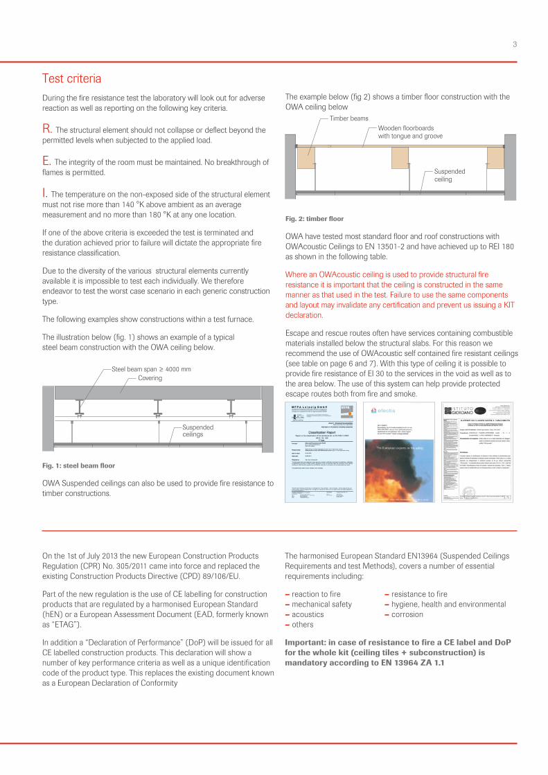
Test criteria During the fire resistance test the laboratory will look out for adverse reaction as well as reporting on the following key criteria.
R. The structural element should not collapse or deflect beyond the permitted levels when subjected to the applied load.
E. The integrity of the room must be maintained. No breakthrough of flames is permitted.
I. The temperature on the non-exposed side of the structural element must not rise more than 140 °K above ambient as an average measurement and no more than 180 °K at any one location.
If one of the above criteria is exceeded the test is terminated and the duration achieved prior to failure will dictate the appropriate fire resistance classification.
Due to the diversity of the various structural elements currently available it is impossible to test each individually. We therefore endeavor to test the worst case scenario in each generic construction type.
The following examples show constructions within a test furnace.
The illustration below (fig. 1) shows an example of a typical steel beam construction with the OWA ceiling below.
Suspended ceilings
Steel beam span ≥ 4000 mmCovering
Fig. 1: steel beam floor
OWA Suspended ceilings can also be used to provide fire resistance to timber constructions.
The example below (fig 2) shows a timber floor construction with the OWA ceiling below Fig. 2: timber floor
OWA have tested most standard floor and roof constructions with OWAcoustic Ceilings to EN 13501-2 and have achieved up to REI 180 as shown in the following table.
Where an OWAcoustic ceiling is used to provide structural fire resis tance it is important that the ceiling is constructed in the same manner as that used in the test. Failure to use the same components and layout may invalidate any certification and prevent us issuing a KIT declaration.
Escape and rescue routes often have services containing combustible materials installed below the structural slabs. For this reason we recommend the use of OWAcoustic self contained fire resistant ceilings (see table on page 6 and 7). With this type of ceiling it is possible to provide fire resistance of EI 30 to the services in the void as well as to the area below. The use of this system can help provide protected escape routes both from fire and smoke.
On the 1st of July 2013 the new European Construction Products Regulation (CPR) No. 305/2011 came into force and replaced the existing Construction Products Directive (CPD) 89/106/EU.
Part of the new regulation is the use of CE labelling for construction products that are regulated by a harmonised European Standard (hEN) or a European Assessment Document (EAD, formerly known as “ETAG”).
In addition a “Declaration of Performance” (DoP) will be issued for all CE labelled construction products. This declaration will show a number of key performance criteria as well as a unique identification code of the product type. This replaces the existing document known as a European Declaration of Conformity
The harmonised European Standard EN13964 (Suspended Ceilings Requirements and test Methods), covers a number of essential requirements including:
– reaction to fire – resistance to fire – mechanical safety – hygiene, health and environmental – acoustics – corrosion – others
Important: in case of resistance to fire a CE label and DoP for the whole kit (ceiling tiles + subconstruction) is mandatory according to EN 13964 ZA 1.1

4 European resistance to fire test
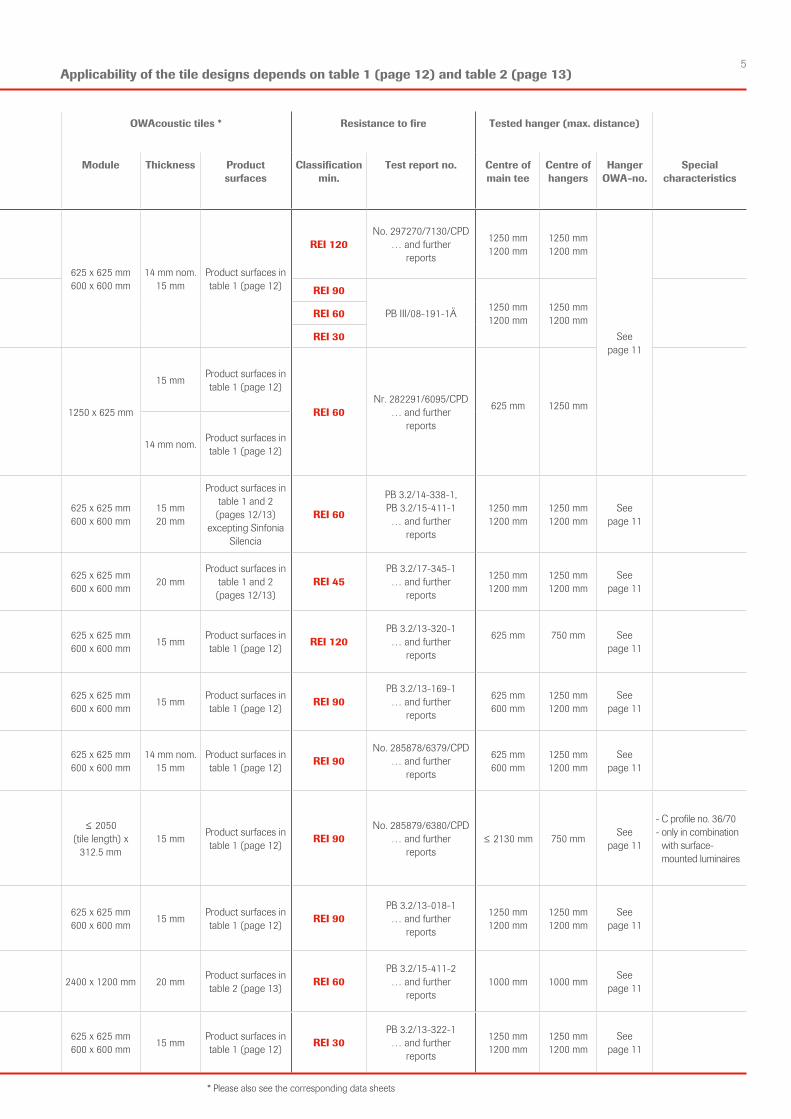
Loadbearing structure Type of suspended ceiling OWAcoustic tiles * Resistance to fire Tested hanger (max. distance)
Types of structure and KIT reference number
Min. thicknessof slab (d)
Min. cavity height (a)
OWAconstruct premium systems
Module Thickness Product surfaces
Classifi cationmin.
Test report no. Centre ofmain tee
Centre ofhangers
HangerOWA-no.
Special characteristics
d
a
d
a
d
a
Steel beam floor KIT-16-01/2012 - S 3KIT-16-01/2012 - S 3a ≥ 120 mm ≥ 200 mm
S 3
S 3a
625 x 625 mm600 x 600 mm
14 mm nom. 15 mm
Product surfaces in table 1 (page 12)
REI 120No. 297270/7130/CPD
… and further reports
1250 mm1200 mm
1250 mm1200 mm
See page 11
Steel beam floor KIT-11-01/2008 - S 3KIT-11-01/2008 - S 3a ≥ 90 mm
≥ 250 mm REI 90
PB III/08-191-1Ä 1250 mm1200 mm
1250 mm1200 mm≥ 150 mm REI 60
≥ 120 mm REI 30
Steel beam floor KIT-27-01/2011 - S 3KIT-27-01/2011 - S 3a
≥ 100 mm ≥ 200 mm 1250 x 625 mm
15 mm Product surfaces in table 1 (page 12)
REI 60Nr. 282291/6095/CPD
… and further reports
625 mm 1250 mm
S 3 14 mm nom. Product surfaces in table 1 (page 12)
Steel beam floor KIT-28-01/2015 - S 3
≥ 90 mm ≥ 250 mm S 3625 x 625 mm600 x 600 mm
15 mm20 mm
Product surfaces in table 1 and 2
(pages 12/13) excepting Sinfonia
Silencia
REI 60
PB 3.2/14-338-1,PB 3.2/15-411-1 … and further
reports
1250 mm1200 mm
1250 mm1200 mm
See page 11
Steel beam floor KIT-29-01/2018 - S 3 ≥ 90 mm ≥ 250 mm S 3
625 x 625 mm600 x 600 mm 20 mm
Product surfaces in table 1 and 2
(pages 12/13)REI 45
PB 3.2/17-345-1… and further
reports
1250 mm1200 mm
1250 mm1200 mm
See page 11
Steel beam floor KIT-24-01/2014 - S 3 ≥ 90 mm ≥ 250 mm
S 3 with mineral wool
625 x 625 mm600 x 600 mm 15 mm Product surfaces in
table 1 (page 12) REI 120PB 3.2/13-320-1… and further
reports
625 mm 750 mm See page 11
Steel beam floor KIT-17-01/2013 - S 15 cliq ≥ 90 mm ≥ 230 mm S 15 cliq
625 x 625 mm600 x 600 mm 15 mm Product surfaces in
table 1 (page 12) REI 90PB 3.2/13-169-1… and further
reports
625 mm600 mm
1250 mm1200 mm
See page 11
Steel beam floor KIT-18-01/2011 - S 15a cliq ≥ 100 mm ≥ 200 mm S 15a cliq
625 x 625 mm600 x 600 mm
14 mm nom. 15 mm
Product surfaces in table 1 (page 12) REI 90
No. 285878/6379/CPD… and further
reports
625 mm600 mm
1250 mm1200 mm
See page 11
Steel beam floor KIT-19-01/2011 - S 18p /S 6a
≥ 100 mm ≥ 200 mm
S 18p
= binder
≤ 2050 (tile length) x
312.5 mm15 mm Product surfaces in
table 1 (page 12) REI 90No. 285879/6380/CPD
… and further reports
≤ 2130 mm 750 mm See page 11
- C profile no. 36/70 - only in combination
with surface-mounted luminaires
Steel beam floor KIT-20-01/2013 - S 1
≥ 90 mm ≥ 185 mm S 1
625 x 625 mm600 x 600 mm 15 mm Product surfaces in
table 1 (page 12) REI 90PB 3.2/13-018-1… and further
reports
1250 mm1200 mm
1250 mm1200 mm
See page 11
Steel beam floor KIT-30-01/2016 - S 7 ≥ 90 mm ≥ 250 mm S 7 2400 x 1200 mm 20 mm Product surfaces in
table 2 (page 13) REI 60PB 3.2/15-411-2… and further
reports1000 mm 1000 mm See
page 11
Steel beam floor KIT-25-01/2014 - S 15 b ≥ 90 mm ≥ 250 mm S 15 b
625 x 625 mm600 x 600 mm 15 mm Product surfaces in
table 1 (page 12) REI 30PB 3.2/13-322-1… and further
reports
1250 mm1200 mm
1250 mm1200 mm
See page 11
Important note:
The KITs listed in the following tables cannot be combined with all OWAcoustic panel designs.
Tables 1 and 2 on pages 12 and 13 must be observed in connection with load-bearing structures and fire resistance durations (REI 30-REI 180).
Load-bearing structures such as:– steel beam floors with
reinforced concrete slabs are also valid for steel and prestressed concrete constructions
– timber constructions– light roof constructions
Please note that only the latest test certificates can be found in the following tables. Expired proofs of usability and systems, which are no longer listed here due to technical reasons, are not available anymore.
5
Loadbearing structure Type of suspended ceiling OWAcoustic tiles * Resistance to fire Tested hanger (max. distance)
Types of structure and KIT reference number
Min. thicknessof slab (d)
Min. cavity height (a)
OWAconstruct premium systems
Module Thickness Product surfaces
Classifi cationmin.
Test report no. Centre ofmain tee
Centre ofhangers
HangerOWA-no.
Special characteristics
d
a
d
a
d
a
Steel beam floor KIT-16-01/2012 - S 3KIT-16-01/2012 - S 3a ≥ 120 mm ≥ 200 mm
S 3
S 3a
625 x 625 mm600 x 600 mm
14 mm nom. 15 mm
Product surfaces in table 1 (page 12)
REI 120No. 297270/7130/CPD
… and further reports
1250 mm1200 mm
1250 mm1200 mm
See page 11
Steel beam floor KIT-11-01/2008 - S 3KIT-11-01/2008 - S 3a ≥ 90 mm
≥ 250 mm REI 90
PB III/08-191-1Ä 1250 mm1200 mm
1250 mm1200 mm≥ 150 mm REI 60
≥ 120 mm REI 30
Steel beam floor KIT-27-01/2011 - S 3KIT-27-01/2011 - S 3a
≥ 100 mm ≥ 200 mm 1250 x 625 mm
15 mm Product surfaces in table 1 (page 12)
REI 60Nr. 282291/6095/CPD
… and further reports
625 mm 1250 mm
S 3 14 mm nom. Product surfaces in table 1 (page 12)
Steel beam floor KIT-28-01/2015 - S 3
≥ 90 mm ≥ 250 mm S 3625 x 625 mm600 x 600 mm
15 mm20 mm
Product surfaces in table 1 and 2
(pages 12/13) excepting Sinfonia
Silencia
REI 60
PB 3.2/14-338-1,PB 3.2/15-411-1 … and further
reports
1250 mm1200 mm
1250 mm1200 mm
See page 11
Steel beam floor KIT-29-01/2018 - S 3 ≥ 90 mm ≥ 250 mm S 3
625 x 625 mm600 x 600 mm 20 mm
Product surfaces in table 1 and 2
(pages 12/13)REI 45
PB 3.2/17-345-1… and further
reports
1250 mm1200 mm
1250 mm1200 mm
See page 11
Steel beam floor KIT-24-01/2014 - S 3 ≥ 90 mm ≥ 250 mm
S 3 with mineral wool
625 x 625 mm600 x 600 mm 15 mm Product surfaces in
table 1 (page 12) REI 120PB 3.2/13-320-1… and further
reports
625 mm 750 mm See page 11
Steel beam floor KIT-17-01/2013 - S 15 cliq ≥ 90 mm ≥ 230 mm S 15 cliq
625 x 625 mm600 x 600 mm 15 mm Product surfaces in
table 1 (page 12) REI 90PB 3.2/13-169-1… and further
reports
625 mm600 mm
1250 mm1200 mm
See page 11
Steel beam floor KIT-18-01/2011 - S 15a cliq ≥ 100 mm ≥ 200 mm S 15a cliq
625 x 625 mm600 x 600 mm
14 mm nom. 15 mm
Product surfaces in table 1 (page 12) REI 90
No. 285878/6379/CPD… and further
reports
625 mm600 mm
1250 mm1200 mm
See page 11
Steel beam floor KIT-19-01/2011 - S 18p /S 6a
≥ 100 mm ≥ 200 mm
S 18p
= binder
≤ 2050 (tile length) x
312.5 mm15 mm Product surfaces in
table 1 (page 12) REI 90No. 285879/6380/CPD
… and further reports
≤ 2130 mm 750 mm See page 11
- C profile no. 36/70 - only in combination
with surface-mounted luminaires
Steel beam floor KIT-20-01/2013 - S 1
≥ 90 mm ≥ 185 mm S 1
625 x 625 mm600 x 600 mm 15 mm Product surfaces in
table 1 (page 12) REI 90PB 3.2/13-018-1… and further
reports
1250 mm1200 mm
1250 mm1200 mm
See page 11
Steel beam floor KIT-30-01/2016 - S 7 ≥ 90 mm ≥ 250 mm S 7 2400 x 1200 mm 20 mm Product surfaces in
table 2 (page 13) REI 60PB 3.2/15-411-2… and further
reports1000 mm 1000 mm See
page 11
Steel beam floor KIT-25-01/2014 - S 15 b ≥ 90 mm ≥ 250 mm S 15 b
625 x 625 mm600 x 600 mm 15 mm Product surfaces in
table 1 (page 12) REI 30PB 3.2/13-322-1… and further
reports
1250 mm1200 mm
1250 mm1200 mm
See page 11
* Please also see the corresponding data sheets
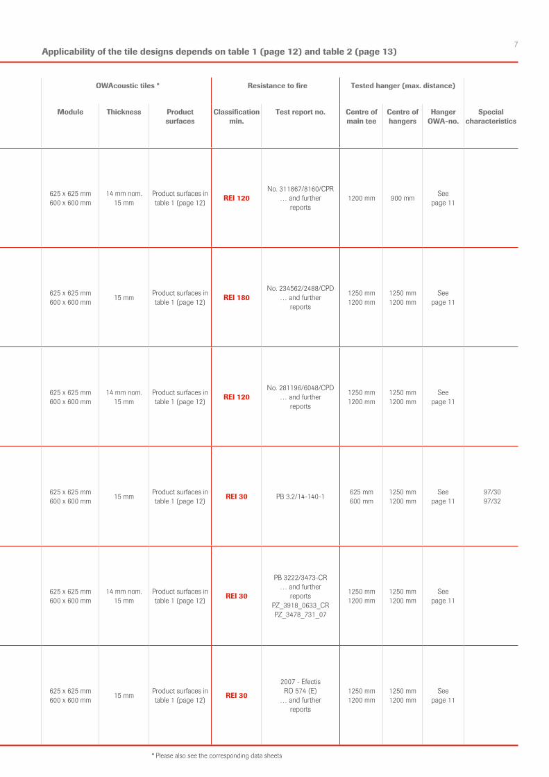
Applicability of the tile designs depends on table 1 (page 12) and table 2 (page 13)
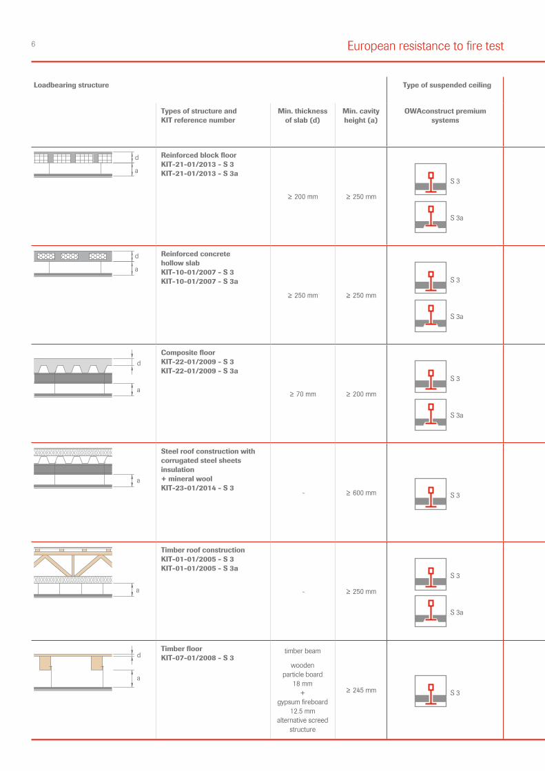
6 European resistance to fire test
Loadbearing structure Type of suspended ceiling OWAcoustic tiles * Resistance to fire Tested hanger (max. distance)
Types of structure and KIT reference number
Min. thicknessof slab (d)
Min. cavity height (a)
OWAconstruct premium systems
Module Thickness Product surfaces
Classifi cationmin.
Test report no. Centre ofmain tee
Centre ofhangers
HangerOWA-no.
Special characteristics
d
a
Reinforced block floor KIT-21-01/2013 - S 3 KIT-21-01/2013 - S 3a
≥ 200 mm ≥ 250 mm
S 3
S 3a
625 x 625 mm600 x 600 mm
14 mm nom.15 mm
Product surfaces in table 1 (page 12) REI 120
No. 311867/8160/CPR… and further
reports1200 mm 900 mm See
page 11
d
a
Reinforced concrete hollow slab KIT-10-01/2007 - S 3 KIT-10-01/2007 - S 3a
≥ 250 mm ≥ 250 mm
S 3
S 3a
625 x 625 mm600 x 600 mm 15 mm Product surfaces in
table 1 (page 12) REI 180No. 234562/2488/CPD
… and further reports
1250 mm1200 mm
1250 mm1200 mm
See page 11
d
a
Composite floor KIT-22-01/2009 - S 3 KIT-22-01/2009 - S 3a
≥ 70 mm ≥ 200 mm
S 3
S 3a
625 x 625 mm600 x 600 mm
14 mm nom.15 mm
Product surfaces in table 1 (page 12) REI 120
No. 281196/6048/CPD… and further
reports
1250 mm1200 mm
1250 mm1200 mm
See page 11
a
Steel roof construction with corrugated steel sheets insulation + mineral wool KIT-23-01/2014 - S 3
- ≥ 600 mm S 3625 x 625 mm600 x 600 mm 15 mm Product surfaces in
table 1 (page 12) REI 30 PB 3.2/14-140-1 625 mm600 mm
1250 mm1200 mm
See page 11
97/3097/32
a
Timber roof construc tionKIT-01-01/2005 - S 3 KIT-01-01/2005 - S 3a
- ≥ 250 mm
S 3
S 3a
625 x 625 mm600 x 600 mm
14 mm nom.15 mm
Product surfaces in table 1 (page 12) REI 30
PB 3222/3473-CR… and further
reportsPZ_3918_0633_CRPZ_3478_731_07
1250 mm1200 mm
1250 mm1200 mm
See page 11
d
a
Timber floor KIT-07-01/2008 - S 3
timber beam
wooden particle board
18 mm +
gypsum fireboard 12.5 mm
alternative screed structure
≥ 245 mm S 3625 x 625 mm600 x 600 mm 15 mm Product surfaces in
table 1 (page 12) REI 30
2007 - EfectisRO 574 (E)
… and further reports
1250 mm1200 mm
1250 mm1200 mm
See page 11
7
Loadbearing structure Type of suspended ceiling OWAcoustic tiles * Resistance to fire Tested hanger (max. distance)
Types of structure and KIT reference number
Min. thicknessof slab (d)
Min. cavity height (a)
OWAconstruct premium systems
Module Thickness Product surfaces
Classifi cationmin.
Test report no. Centre ofmain tee
Centre ofhangers
HangerOWA-no.
Special characteristics
d
a
Reinforced block floor KIT-21-01/2013 - S 3 KIT-21-01/2013 - S 3a
≥ 200 mm ≥ 250 mm
S 3
S 3a
625 x 625 mm600 x 600 mm
14 mm nom.15 mm
Product surfaces in table 1 (page 12) REI 120
No. 311867/8160/CPR… and further
reports1200 mm 900 mm See
page 11
d
a
Reinforced concrete hollow slab KIT-10-01/2007 - S 3 KIT-10-01/2007 - S 3a
≥ 250 mm ≥ 250 mm
S 3
S 3a
625 x 625 mm600 x 600 mm 15 mm Product surfaces in
table 1 (page 12) REI 180No. 234562/2488/CPD
… and further reports
1250 mm1200 mm
1250 mm1200 mm
See page 11
d
a
Composite floor KIT-22-01/2009 - S 3 KIT-22-01/2009 - S 3a
≥ 70 mm ≥ 200 mm
S 3
S 3a
625 x 625 mm600 x 600 mm
14 mm nom.15 mm
Product surfaces in table 1 (page 12) REI 120
No. 281196/6048/CPD… and further
reports
1250 mm1200 mm
1250 mm1200 mm
See page 11
a
Steel roof construction with corrugated steel sheets insulation + mineral wool KIT-23-01/2014 - S 3
- ≥ 600 mm S 3625 x 625 mm600 x 600 mm 15 mm Product surfaces in
table 1 (page 12) REI 30 PB 3.2/14-140-1 625 mm600 mm
1250 mm1200 mm
See page 11
97/3097/32
a
Timber roof construc tionKIT-01-01/2005 - S 3 KIT-01-01/2005 - S 3a
- ≥ 250 mm
S 3
S 3a
625 x 625 mm600 x 600 mm
14 mm nom.15 mm
Product surfaces in table 1 (page 12) REI 30
PB 3222/3473-CR… and further
reportsPZ_3918_0633_CRPZ_3478_731_07
1250 mm1200 mm
1250 mm1200 mm
See page 11
d
a
Timber floor KIT-07-01/2008 - S 3
timber beam
wooden particle board
18 mm +
gypsum fireboard 12.5 mm
alternative screed structure
≥ 245 mm S 3625 x 625 mm600 x 600 mm 15 mm Product surfaces in
table 1 (page 12) REI 30
2007 - EfectisRO 574 (E)
… and further reports
1250 mm1200 mm
1250 mm1200 mm
See page 11
* Please also see the corresponding data sheets
Applicability of the tile designs depends on table 1 (page 12) and table 2 (page 13)
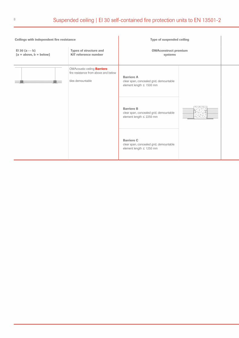
8 Suspended ceiling | EI 30 self-contained fire protection units to EN 13501-2
Ceilings with independent fire resistance Type of suspended ceiling OWAcoustic tiles/ elements
Resistance to fire Tested hanger (max. distance)
EI 30 (a ↔ b) [a = above, b = below]
Types of structure and KIT reference number
OWAconstruct premium systems
Module Thickness Product surfaces
Classifi-cationmin.
Test report no. Centre ofhangers
HangerOWA-no.
OWAcoustic ceiling Barriere fire resistance from above and below
tiles demountableBarriere Aclear span, concealed grid, demountableelement length ≤ 1500 mm
Type Awidth: 300 mm, 312,5 mm
length: ≤ 1500 mm40 mm
Sternbild Cosmos/NCosmos/O
EI 30a ↔ b
PB 3.2/19-100-1PB 3.2/19-100-2
Type A≤ 800 mm
Nonius hanger no. 79/...
Barriere Bclear span, concealed grid, demountableelement length ≤ 2250 mm
Type Bwidth: 300 mm, 312,5 mm
length: 1800 mm, 2000 mm, 2250 mm44 mm PB 3.2/18-300-4
PB 3.2/18-300-5Type B
≤ 625 mm
Barriere Cclear span, concealed grid, demountableelement length ≤ 1250 mm
Type Cwidth: 625 mm
length: 1250 mm40 mm PB 3.2/18-262-1
PB 3.2/18-262-3Type C
≤ 625 mm
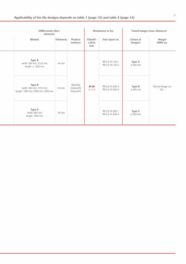
9Applicability of the tile designs depends on table 1 (page 12) and table 2 (page 13)
Ceilings with independent fire resistance Type of suspended ceiling OWAcoustic tiles/ elements
Resistance to fire Tested hanger (max. distance)
EI 30 (a ↔ b) [a = above, b = below]
Types of structure and KIT reference number
OWAconstruct premium systems
Module Thickness Product surfaces
Classifi-cationmin.
Test report no. Centre ofhangers
HangerOWA-no.
OWAcoustic ceiling Barriere fire resistance from above and below
tiles demountableBarriere Aclear span, concealed grid, demountableelement length ≤ 1500 mm
Type Awidth: 300 mm, 312,5 mm
length: ≤ 1500 mm40 mm
Sternbild Cosmos/NCosmos/O
EI 30a ↔ b
PB 3.2/19-100-1PB 3.2/19-100-2
Type A≤ 800 mm
Nonius hanger no. 79/...
Barriere Bclear span, concealed grid, demountableelement length ≤ 2250 mm
Type Bwidth: 300 mm, 312,5 mm
length: 1800 mm, 2000 mm, 2250 mm44 mm PB 3.2/18-300-4
PB 3.2/18-300-5Type B
≤ 625 mm
Barriere Cclear span, concealed grid, demountableelement length ≤ 1250 mm
Type Cwidth: 625 mm
length: 1250 mm40 mm PB 3.2/18-262-1
PB 3.2/18-262-3Type C
≤ 625 mm
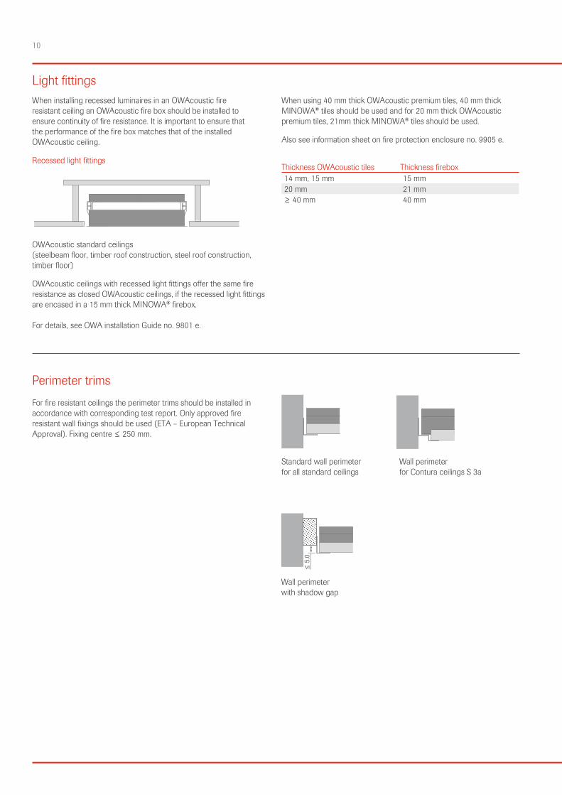
10
Light fittingsWhen installing recessed luminaires in an OWAcoustic fire resistant ceiling an OWAcoustic fire box should be installed to ensure continuity of fire resistance. It is important to ensure that the performance of the fire box matches that of the installed OWAcoustic ceiling.
Recessed light fittings
OWAcoustic standard ceilings (steelbeam floor, timber roof construction, steel roof construction, timber floor)
OWAcoustic ceilings with recessed light fittings offer the same fire resistance as closed OWAcoustic ceilings, if the recessed light fittings are encased in a 15 mm thick MINOWA® firebox. For details, see OWA installation Guide no. 9801 e.
When using 40 mm thick OWAcoustic premium tiles, 40 mm thick MINOWA® tiles should be used and for 20 mm thick OWAcoustic premium tiles, 21mm thick MINOWA® tiles should be used.
Also see information sheet on fire protection enclosure no. 9905 e.
Thickness OWAcoustic tiles Thickness firebox14 mm, 15 mm 15 mm20 mm 21 mm≥ 40 mm 40 mm
Perimeter trimsFor fire resistant ceilings the perimeter trims should be installed in accordance with corresponding test report. Only approved fire resistant wall fixings should be used (ETA – European Technical Approval). Fixing centre ≤ 250 mm.
Standard wall perimeter Wall perimeter for all standard ceilings for Contura ceilings S 3a
Wall perimeter with shadow gap
≤ 5
.0
11
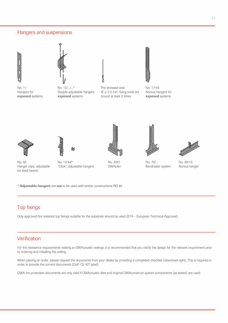
Hangers and suspensions
No. 11Hangers forexposed systems
No. 12/.../...*Double-adjustable hangersexposed systems
Pre-stressed wireØ ≥ 2.0 mm; fixing ends arebound at least 3 times
No. 17/45Nonius hangers forexposed systems
No. 90Hanger clips, adjustablefor steal beams
No. 12/44*“Click”, adjustable hangers
No. 2001OWAplan
No. 79/...Bandraster system
No. 09/10Nonius hanger
* Adjustable hangers are not to be used with timber constructions REI 90.
Top fixingsOnly approved fire resistant top fixings suitable for the substrate should be used (ETA – European Technical Approval).
VerificationFor fire resistance requirements relating to OWAcoustic ceilings, it is recommended that you clarify the design for the relevant requirement prior to ordering and installing the ceiling.
When placing an order, please request the documents from your dealer by providing a completed checklist (download right). This is required in order to provide the correct documents (DoP, CE-KIT label).
OWA fire protection documents are only valid if OWAcoustic-tiles and original OWAconstruct system components (as tested) are used.
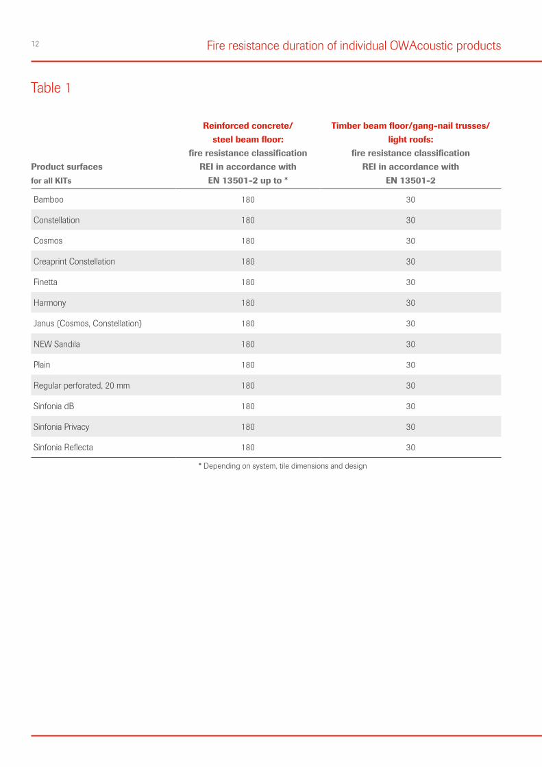
12 Fire resistance duration of individual OWAcoustic products
Table 1
Product surfacesfor all KITs
Reinforced concrete/ steel beam floor:
fire resistance classification REI in accordance with
EN 13501-2 up to *
Timber beam floor/gang-nail trusses/ light roofs:
fire resistance classification REI in accordance with
EN 13501-2
Bamboo 180 30
Constellation 180 30
Cosmos 180 30
Creaprint Constellation 180 30
Finetta 180 30
Harmony 180 30
Janus (Cosmos, Constellation) 180 30
NEW Sandila 180 30
Plain 180 30
Regular perforated, 20 mm 180 30
Sinfonia dB 180 30
Sinfonia Privacy 180 30
Sinfonia Reflecta 180 30 * Depending on system, tile dimensions and design
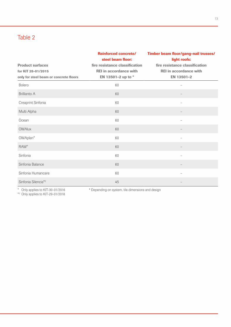
13
Table 2
Product surfacesfor KIT 28-01/2015
only for steel beam or concrete floors
Reinforced concrete/ steel beam floor:
fire resistance classification REI in accordance with
EN 13501-2 up to *
Timber beam floor/gang-nail trusses/ light roofs:
fire resistance classification REI in accordance with
EN 13501-2
Bolero 60 –
Brillianto A 60 –
Creaprint Sinfonia 60 –
Multi Alpha 60 –
Ocean 60 –
OWAlux 60 –
OWAplan° 60 –
RAW° 60 –
Sinfonia 60 –
Sinfonia Balance 60 –
Sinfonia Humancare 60 –
Sinfonia Silencia°2 45 – ° Only applies to KIT-30-01/2016 * Depending on system, tile dimensions and design°2 Only applies to KIT-29-01/2018
14 Notes

Technical assistanceThis brochure provides a very brief outline of European Standard EN 13501 and how OWAcoustic ceilings can help meet your fire resistance requirements.
If you require further information or assistance on any aspect of your proposed ceiling installation please contact us or visit our website.
OWAconsult information service:Germanytel +49 9373 201-444fax +49 9373 [email protected]
The information provided in this leaflet is based on the standards and data available at the time of publication. Any performance, warranties or guarantees provided, expressed or implied, are subject to the exclusive use of OWA components and the installation of those components in accordance with our recommendations. Failure to adhere to these conditions will result in the invalidation of any performance claims, warranties or guarantees and rejection of any liability. OWA reserves the right to make any technical improvements to the products, systems or services without prior notice. All goods and services are supplied in accordance with our current Terms and Conditions of Sale. Errors excepted!
Product warranties
Broc
hure
950
0 eu
/e10
1900
The information in this brochure is up-to-date at the time of publication. Errors and mistakes excepted. With the publication of this issue, all previous brochures no. 9500 eu/e are invalid. Please contact our competence team OWAconsult for specific advice. Our experts will be happy to answer your questions under the following contact details: tel: +49 9373 201-444 or e-mail: [email protected]
Odenwald Faserplattenwerk GmbH Dr.-F.-A.-Freundt-Straße 3 | 63916 Amorbach | Germanytel +49 9373 201-0 | [email protected]


