Finite Element Design and Manufacturing of a Nylon-String ...

Finite State Machine Design
Adapted from slides by R. H. Katz
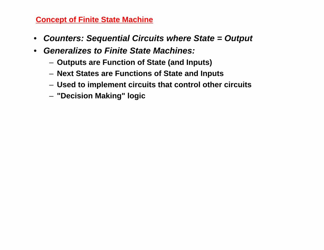
• Counters: Sequential Circuits where State = Output
• Generalizes to Finite State Machines:– Outputs are Function of State (and Inputs)
– Next States are Functions of State and Inputs
– Used to implement circuits that control other circuits
– "Decision Making" logic
Concept of Finite State Machine

Concept of Finite State Machine
Computer Hardware = Datapath + Control
RegistersCombinational Functional
Units (e.g., ALU)Busses
FSM generating sequencesof control signals
Instructs datapath what todo next
"Puppet"
"Puppeteer who pulls thestrings"
Qualifiers
Control
Control
Datapath
State
ControlSignalOutputs
QualifiersandInputs

Concept of Finite State Machine
Example: Odd Parity Checker
Even [0]
Odd [1]
Reset
0
0
1 1
Assert output whenever input bit stream has odd # of 1's
StateDiagram
Present State Even Even Odd Odd
Input 0 1 0 1
Next State Even Odd Odd Even
Output 0 0 1 1
Symbolic State Transition Table
Output 0 0 1 1
Next State 0 1 1 0
Input 0 1 0 1
Present State 0 0 1 1
Encoded State Transition Table

Concept of Finite State Machine
Example: Odd Parity Checker
Next State/Output Functions
NS = PS xor PI; OUT = PS
D
R
Q
Q
Input
CLK PS/Output
\Reset
NS
D FF Implementation
T
R
Q
Q
Input
CLK
Output
\Reset
T FF Implementation
Timing Behavior: Input 1 0 0 1 1 0 1 0 1 1 1 0
Clk
Output
Input 1 0 0 1 1 0 1 0 1 1 1 0
1 1 0 1 0 0 1 1 0 1 1 1

Basic Design Approach
Six Step Process
1. Understand the statement of the Specification
2. Obtain an abstract specification of the FSM(state table or state diagram)
3. Perform a state minimization
4. Perform state assignment
(# state variables) ≥ log2 (#states)
5. Choose FF types to implement FSM state registerand build excitation table
6. Combinational circuit minimization

Basic Design Approach
Example: Vending Machine FSM
General Machine Concept:deliver package of gum after 15 cents deposited
single coin slot for dimes, nickels
no change
Block Diagram
Step 1. Understand the problem:
Vending Machine
FSM
N
D
Reset
Clk
OpenCoin
SensorGum
Release Mechanism
Draw a picture!

Vending Machine Example
Tabulate typical input sequences:three nickelsnickel, dimedime, nickeltwo dimestwo nickels, dime
Draw state diagram:
Inputs: N, D, reset
Output: open
Step 2. Map into more suitable abstract representation
Reset
N
N
N
D
D
N D
[open]
[open] [open] [open]
S0
S1 S2
S3 S4 S5 S6
S8
[open]
S7
D
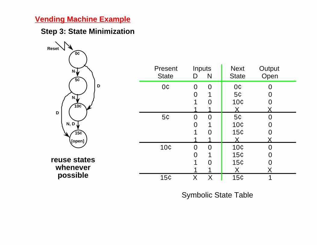
Vending Machine Example
Step 3: State Minimization
Reset
N
N
N, D
[open]
15¢
0¢
5¢
10¢
D
D
reuse stateswheneverpossible
Symbolic State Table
Present State
0¢
5¢
10¢
15¢
D
0 0 1 1 0 0 1 1 0 0 1 1 X
N
0 1 0 1 0 1 0 1 0 1 0 1 X
Inputs Next State
0¢5¢10¢X 5¢10¢15¢X
10¢15¢15¢X
15¢
Output Open
0 0 0 X 0 0 0 X 0 0 0 X 1
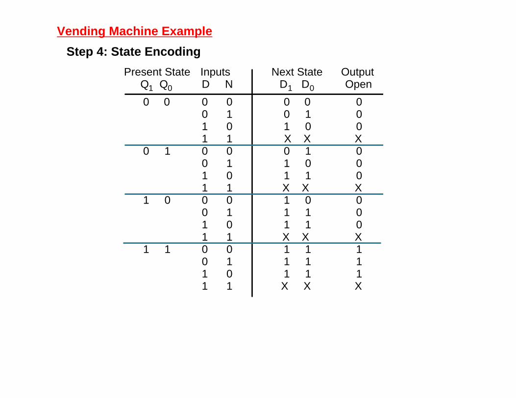
Vending Machine Example
Step 4: State Encoding
Next State D 1 D 0
0 0 0 1 1 0 X X 0 1 1 0 1 1 X X 1 0 1 1 1 1 X X 1 1 1 1 1 1 X X
Present State Q 1 Q 0
0 0
0 1
1 0
1 1
D
0 0 1 1 0 0 1 1 0 0 1 1 0 0 1 1
N
0 1 0 1 0 1 0 1 0 1 0 1 0 1 0 1
Inputs Output Open
0 0 0 X 0 0 0 X 0 0 0 X 1 1 1 X

Vending Machine Example
Step 5. Choose FF type for implementation
J-K FF
excitation tableNext State
D 1 D 0
0 0 0 1 1 0 X X 0 1 1 0 1 1 X X 1 0 1 1 1 1 X X 1 1 1 1 1 1 X X
Present State Q 1 Q 0
0 0
0 1
1 0
1 1
D
0 0 1 1 0 0 1 1 0 0 1 1 0 0 1 1
N
0 1 0 1 0 1 0 1 0 1 0 1 0 1 0 1
Inputs K 1
X X X X X X X X 0 0 0 X 0 0 0 X
K 0
X X X X 0 1 0 X X X X X 0 0 0 X
J 1
0 0 1 X 0 1 1 X X X X X X X X X
J 0
0 1 0 X X X X X 0 1 1 X X X X X
Output Open
0 0 0 X 0 0 0 X 0 0 0 X 1 1 1 X
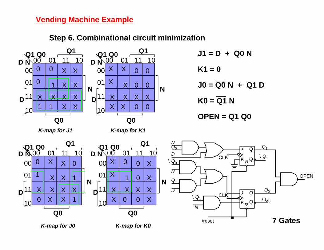
K-map for K1K-map for J1
K-map for K0K-map for J0
J1 = D + Q0 N
K1 = 0
J0 = Q0 N + Q1 D
K0 = Q1 N
OPEN = Q1 Q0
7 Gates
OPEN Q 1
\ Q 0
N
Q 0 J
K R
Q
Q
J
K R
Q
Q
Q 0
\ Q 1
\ Q 1
\ Q 0
Q 1
\reset
D
D
N
N
CLK
CLK
Vending Machine Example
Step 6. Combinational circuit minimization
Q1 Q0D N
Q1
Q0
D
N
00 01 11 10
00
01
11
10
X X
1
X X X X
1 1 X X
X X
Q1 Q0D N
Q1
Q0
D
N
00 01 11 10
00
01
11
10
0 0
X
X X X X
X X 0 0
0 0
X
X
X
Q1 Q0 Q1
Q0
D
N
00 01 11 10
00
01
11
10
X 0
X
X X X X
0 X X 1
X 1
0
1
X
Q1 Q0 Q1
Q0
D
N
00 01 11 10
00
01
11
10
0 X
1
X X X X
X 0 0 X
0 X
X
X
0
0 0
0
D N D N

Vending Machine Example
D FF easiest to use
D1 = Q1 + D + Q0 N
D0 = N Q0 + Q0 N + Q1 N + Q1 D
OPEN = Q1 Q0
8 Gates
CLK
OPEN
CLK
Q 0
D
R
Q
Q
D
R
Q
Q
\ Q 1
\reset
\reset
\ Q 0
\ Q 0
Q 0
Q 0
Q 1
Q 1
Q 1
Q 1
D
D
N
N
N
\ N
D 1
D 0
K-map for OpenK-map for D0 K-map for D1
Q1 Q0D N
Q1
Q0
D
N
Q1 Q0D N
Q1
Q0
D
N
Q1 Q0D N
Q1
Q0
D
N
00 01 11 10 00 01 11 10 00 01 11 10
00
01
11
10
00
01
11
10
00
01
11
10
1 1
1
X X X X
1 1 1 1
1 1
1 1
1 1 1
X X X X
1 1 1
X X X X
1
1
1
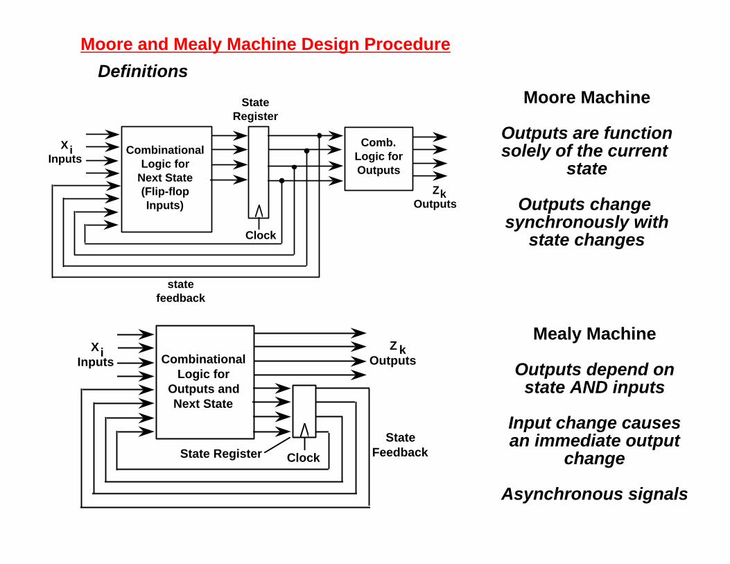
Moore and Mealy Machine Design Procedure
Definitions
Moore Machine
Outputs are functionsolely of the current
state
Outputs change synchronously with
state changes
Mealy Machine
Outputs depend onstate AND inputs
Input change causesan immediate output
change
Asynchronous signals
State Register Clock
State Feedback
Combinational Logic for
Outputs and Next State
X Inputs
i Z Outputs
k
Clock
state feedback
Combinational Logic for
Next State (Flip-flop Inputs)
State Register
Comb. Logic for Outputs
Z Outputs
k
X Inputs
i
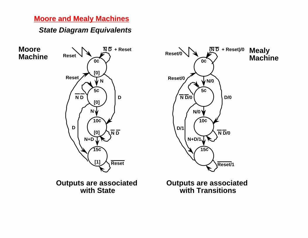
Moore and Mealy Machines
State Diagram Equivalents
Outputs are associated with State
Outputs are associated with Transitions
Reset/0
N/0
N/0
N+D/1
15¢
0¢
5¢
10¢
D/0
D/1
(N D + Reset)/0
Reset/0
Reset/1
N D/0
N D/0
MooreMachine Reset
N
N
N+D
[1]
15¢
0¢
5¢
10¢
D
[0]
[0]
[0]
D
N D + Reset
Reset
Reset
N D
N D
MealyMachine

Moore and Mealy MachinesStates vs. Transitions
Mealy Machine typically has fewer states than Moore Machinefor same output sequence
Same I/O behavior
Different # of states
1
1
0
1
2
0
0
[0]
[0]
[1]
1/0
0
1
0/0
0/0
1/1
1
0

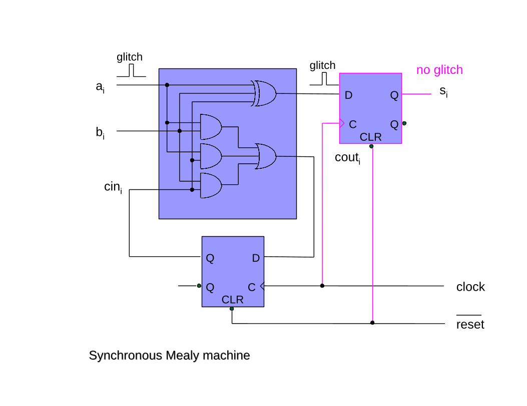
Moore and Mealy Machines
Synchronous Mealy Machine
latched state AND outputs
avoids glitchy outputs!
State Register Clock
Clock
Combinational Logic for
Outputs and Next State
state feedback
X Inputs
i Z Outputs
k

• Mealy model of a serial adder
Q D
Q C
ai
bi
si
couti
cini
glitchglitch
CLRclock
reset

• State table
• State diagram
present input ai, bi
presentstate cini
01
00 01 11 10
0, 00, 1
0, 11, 0
1, 01, 1
0, 11, 0
next state couti, output si
S0cini=0
reset
S1cini=1
01/010/011/1
00/001/110/1
11/0
00/1

• Mealy to Moore conversion
S0cini=0
reset
S1cini=1
01/010/011/1
00/001/110/1
11/0
00/1
S00cini=0si=0
reset
S10cini=1si=0
011000
11
00
S01
cini=0si=1
S11
cini=1si=1
11
000110
0110 00
11
11 0110

present input ai, bi
presentstate cini
S00S01S10S11
00 01 11 10
S00S00S01S01
S01S01S10S10
S10S10S11S11
S01S01S10S10
next state
output si
0101
State assignment :State assignment :
S = (cini si) S00 = 00S01 = 01S10 = 10S11 = 11
4 states : 2 FFs

Q D
Q C
ai
bi
si
couti
cini
glitchglitch
CLRclock
reset
Q D
Q CCLR
no glitch
delayed by1 clock period
more states (FFs)
Q D
Q C
ai
bi
si
couti
cini
glitchglitch
CLRclock
reset
QD
QCCLR
no glitch
Synchronous Mealy machineSynchronous Mealy machine

Timing Control and Clocks
clock
input combinationallogic
output
FF
tc
tff
tsu th
tw
T
T > tffmax + tc
max + tsumax
th < tffmin + tc
min
(usually th < tffmin)
tw > twmin

tPLH = tPHL = 2 nstc
max = 6 ns (use timing analyzer)tff
max = tsumax = 5 ns
E = 4 ns (tolerance)T = tff
max + tcmax + tsu
max + E = 20 ns (50 MHz clock)tw
min = 3 ns
tsu = 5 nstff = 5 ns
tw = 10 ns
T = 20 ns
tc = 6 ns E = 4 ns
Finite State Machine Word Problems
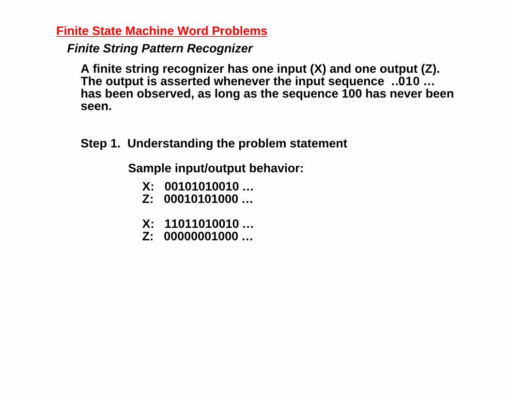
Finite String Pattern Recognizer
A finite string recognizer has one input (X) and one output (Z).The output is asserted whenever the input sequence …010 …has been observed, as long as the sequence 100 has never beenseen.
Step 1. Understanding the problem statement
Sample input/output behavior:
X: 00101010010 …Z: 00010101000 …
X: 11011010010 …Z: 00000001000 …

Finite State Machine Word Problems
Finite String Recognizer
Step 2. Draw State Diagrams for the strings that must berecognized. i.e., 010 and 100.
Moore State DiagramReset signal places
FSM in S0
Outputs 1 Loops in State
S0 [0]
S1 [0]
S2 [0]
S3 [1]
S4 [0]
S5 [0]
S6 [0]
Reset
0
1
0
1
0
00,1

Finite State Machine Word ProblemsFinite String Recognizer
Exit conditions from state S3: have recognized …010if next input is 0 then have …0100!if next input is 1 then have …0101 = … 01 (state S2)
S0 [0]
S1 [0]
S2 [0]
S3 [1]
S4 [0]
S5 [0]
S6 [0]
Reset
0
1
0
1
0
00,1
1
0
… 01
… 010… 100
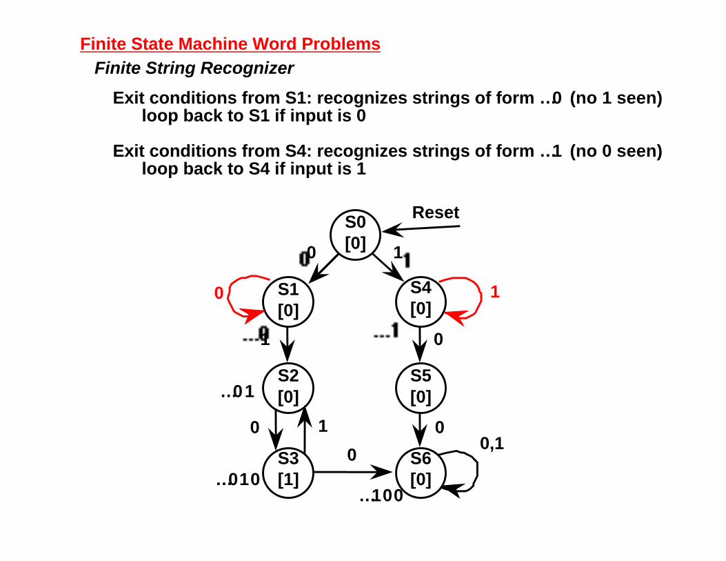
Finite State Machine Word ProblemsFinite String Recognizer
Exit conditions from S1: recognizes strings of form … 0 (no 1 seen)loop back to S1 if input is 0
Exit conditions from S4: recognizes strings of form … 1 (no 0 seen)loop back to S4 if input is 1
S0 [0]
S1 [0]
S2 [0]
S3 [1]
S4 [0]
S5 [0]
S6 [0]
Reset
0 1
0
1
0
1
0
00,1
1
0
… 01
… 010… 100

Finite State Machine Word ProblemsFinite String Recognizer
S2, S5 with incomplete transitions
S2 = …01; If next input is 1, then string could be prefix of (01)1(00)S4 handles just this case!
S5 = …10; If next input is 1, then string could be prefix of (10)1(0)S2 handles just this case!
Final State Diagram
S0 [0]
S1 [0]
S2 [0]
S3 [1]
S4 [0]
S5 [0]
S6 [0]
Reset
0 1
0
1
0
1
0
00,1
1
0
… 01
… 010… 100
1
1
… 10
Finite State Machine Word Problems
Finite String RecognizerReview of Process:
• Write down sample inputs and outputs to understand specification
• Write down sequences of states and transitions for the sequencesto be recognized
• Add missing transitions; reuse states as much as possible
• Verify I/O behavior of your state diagram to insure it functionslike the specification

Finite State Machine Word ProblemsTraffic Light Controller
A busy highway is intersected by a little used farmroad. DetectorsC sense the presence of cars waiting on the farmroad. With no caron farmroad, light remain green in highway direction. If vehicle onfarmroad, highway lights go from Green to Yellow to Red, allowing the farmroad lights to become green. These stay green only as long as a farmroad car is detected but never longer than a set interval. When these are met, farm lights transition from Green to Yellow to Red, allowing highway to return to green. Even if farmroad vehicles are waiting, highway gets at least a set interval as green.
Assume you have an interval timer that generates a short time pulse(TS) and a long time pulse (TL) in response to a set (ST) signal. TSis to be used for timing yellow lights and TL for green lights.

Finite State Machine Word ProblemsTraffic Light Controller
Picture of Highway/Farmroad Intersection:
Highway
Highway
Farmroad
Farmroad
HL
HL
FL
FL
C
C
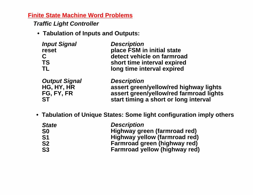
Finite State Machine Word ProblemsTraffic Light Controller
• Tabulation of Inputs and Outputs:
Input SignalresetCTSTL
Output SignalHG, HY, HRFG, FY, FRST
Descriptionplace FSM in initial statedetect vehicle on farmroadshort time interval expiredlong time interval expired
Descriptionassert green/yellow/red highway lightsassert green/yellow/red farmroad lightsstart timing a short or long interval
• Tabulation of Unique States: Some light configuration imply others
StateS0S1S2S3
DescriptionHighway green (farmroad red)Highway yellow (farmroad red)Farmroad green (highway red)Farmroad yellow (highway red)
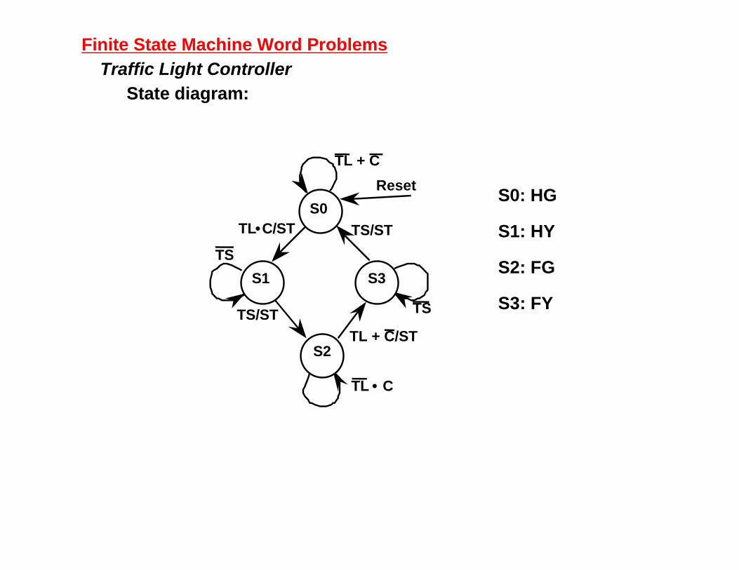
Finite State Machine Word ProblemsTraffic Light Controller
State diagram:
S0: HG
S1: HY
S2: FG
S3: FY
Reset
TL + C
S0TL•C/ST
TS
S1 S3
S2
TS/ST
TS/ST
TL + C/ST
TS
TL • C