Finite Element Modeling of Confined Concrete-II Plastic-Damage Model
12
Engineering Structures 32 (2010) 680–691 Contents lists available at ScienceDirect Engineering Structures journal homepage: www.elsevier.com/locate/engstruct Finite element modeling of confined concrete-II: Plastic-damage model T. Yu a , J.G. Teng a,* , Y.L. Wong a , S.L. Dong b a Department of Civil and Structural Engineering, The Hong Kong Polytechnic University, Hong Kong, China b Department of Civil Engineering, Zhejiang University, Hangzhou 310027, China article info Article history: Received 14 May 2008 Received in revised form 12 November 2009 Accepted 22 November 2009 Available online 4 January 2010 Keywords: Confinement Concrete FRP Plasticity Damage Finite elements Modeling abstract This paper presents a modified plastic-damage model within the theoretical framework of the Con- crete Damaged Plasticity Model (CDPM) in ABAQUS for the modeling of confined concrete under non-uniform confinement. The modifications proposed for the CDPM include a damage parameter, a strain-hardening/softening rule and a flow rule, all of which are confinement-dependent, and a pressure- dependent yield criterion. The distinct characteristics of non-uniformly confined concrete are also included in this model by defining an effective confining pressure. Finite element models incorporat- ing the proposed CDPM model were developed for concrete in a number of confinement scenarios, in- cluding active confinement, biaxial compression, FRP-confined circular and square columns, and hybrid FRP-concrete-steel double-skin tubular columns. The finite element predictions are shown to be in close agreement with the existing test results. The limitations of the proposed model are also discussed towards the end of the paper, pointing to future research needs in this area. © 2009 Elsevier Ltd. All rights reserved. 1. Introduction Fiber-reinforced polymer (FRP) jackets have been widely used to confine reinforced concrete columns to enhance their structural performance. Consequently, many studies over the past decade have been devoted to the behavior and modeling of FRP-confined concrete. Most of these studies have been concerned with the be- havior of concrete in FRP-confined circular columns, where the confinement is uniform around the circumference (e.g. uniform confinement) [1]. Stress–strain models now exist that can provide close predictions of the behavior of such FRP-confined concrete [1]. By contrast, the behavior of FRP-confined concrete in columns of other section forms (e.g. rectangular sections, elliptical sections and annular sections) has received more limited attention and ac- curate stress–strain models have not been developed yet for such non-uniformly confined concrete. Of the different scenarios of non-uniform FRP confinement, FRP-confined rectangular sections have received the most atten- tion (e.g. [2–6]), and several stress–strain models are now avail- able for FRP-confined concrete in rectangular sections. Since FRP confinement is much less effective for rectangular sections than for circular sections, the possibility of modifying a rectangular sec- tion into an elliptical section has been explored (e.g. [7]) but the * Corresponding author. Tel.: +852 2766 6012; fax: +852 2766 1354. E-mail address: [email protected] (J.G. Teng). current understanding of the behavior of concrete in FRP-confined elliptical sections is very limited. Another important form of FRP- confined section is the annular section, found in a number of dif- ferent column forms. Fam and Rizkalla [8] and Becque et al. [9] presented their attempts to model FRP-confined circular hollow concrete sections and FRP-concrete double-skin tubular columns (DSTCs) composed of concrete sandwiched between two FRP tubes as the skins but they have had limited success [10]. Teng et al. [11] recently proposed a new form of hybrid columns named hybrid FRP-concrete-steel DSTCs which consist of an outer tube made of FRP and an inner tube made of steel, with the space between filled with concrete (Fig. 1). Accurate stress–strain models for FRP- confined concrete in annular sections have not yet been found in the published literature. It is well known that in a non-circular FRP-confined sec- tion, the confining pressure provided by the jacket varies around the perimeter and the axial stress in the concrete varies over the section. Existing stress–strain models for non-uniformly con- fined concrete generally adopt the so-called ‘‘design-oriented ap- proach’’ [12] so that the models provide a relationship between the average axial stress of the concrete to the axial strain, with the prediction of the lateral strains ignored. This design-oriented approach relies on the direct interpretation and regression of test data, and leads to one-dimensional stress–strain models in closed- form algebraic expressions. It offers the simplicity needed for such models to be used in design, but is limited in the way that it is empirically based on limited test data. The alternative ‘‘analysis- oriented model’’ well developed for concrete with uniform FRP 0141-0296/$ – see front matter © 2009 Elsevier Ltd. All rights reserved. doi:10.1016/j.engstruct.2009.11.013
-
Upload
aref-abadel -
Category
Documents
-
view
145 -
download
14
Transcript of Finite Element Modeling of Confined Concrete-II Plastic-Damage Model

Engineering Structures 32 (2010) 680–691
Contents lists available at ScienceDirect
Engineering Structures
journal homepage: www.elsevier.com/locate/engstruct
Finite element modeling of confined concrete-II: Plastic-damage modelT. Yu a, J.G. Teng a,∗, Y.L. Wong a, S.L. Dong ba Department of Civil and Structural Engineering, The Hong Kong Polytechnic University, Hong Kong, Chinab Department of Civil Engineering, Zhejiang University, Hangzhou 310027, China
a r t i c l e i n f o
Article history:Received 14 May 2008Received in revised form12 November 2009Accepted 22 November 2009Available online 4 January 2010
Keywords:ConfinementConcreteFRPPlasticityDamageFinite elementsModeling
a b s t r a c t
This paper presents a modified plastic-damage model within the theoretical framework of the Con-crete Damaged Plasticity Model (CDPM) in ABAQUS for the modeling of confined concrete undernon-uniform confinement. The modifications proposed for the CDPM include a damage parameter, astrain-hardening/softening rule and a flow rule, all of which are confinement-dependent, and a pressure-dependent yield criterion. The distinct characteristics of non-uniformly confined concrete are alsoincluded in this model by defining an effective confining pressure. Finite element models incorporat-ing the proposed CDPM model were developed for concrete in a number of confinement scenarios, in-cluding active confinement, biaxial compression, FRP-confined circular and square columns, and hybridFRP-concrete-steel double-skin tubular columns. The finite element predictions are shown to be in closeagreementwith the existing test results. The limitations of the proposedmodel are also discussed towardsthe end of the paper, pointing to future research needs in this area.
© 2009 Elsevier Ltd. All rights reserved.
1. Introduction
Fiber-reinforced polymer (FRP) jackets have been widely usedto confine reinforced concrete columns to enhance their structuralperformance. Consequently, many studies over the past decadehave been devoted to the behavior and modeling of FRP-confinedconcrete. Most of these studies have been concerned with the be-havior of concrete in FRP-confined circular columns, where theconfinement is uniform around the circumference (e.g. uniformconfinement) [1]. Stress–strain models now exist that can provideclose predictions of the behavior of such FRP-confined concrete [1].By contrast, the behavior of FRP-confined concrete in columns ofother section forms (e.g. rectangular sections, elliptical sectionsand annular sections) has received more limited attention and ac-curate stress–strain models have not been developed yet for suchnon-uniformly confined concrete.Of the different scenarios of non-uniform FRP confinement,
FRP-confined rectangular sections have received the most atten-tion (e.g. [2–6]), and several stress–strain models are now avail-able for FRP-confined concrete in rectangular sections. Since FRPconfinement is much less effective for rectangular sections thanfor circular sections, the possibility of modifying a rectangular sec-tion into an elliptical section has been explored (e.g. [7]) but the
∗ Corresponding author. Tel.: +852 2766 6012; fax: +852 2766 1354.E-mail address: [email protected] (J.G. Teng).
0141-0296/$ – see front matter© 2009 Elsevier Ltd. All rights reserved.doi:10.1016/j.engstruct.2009.11.013
current understanding of the behavior of concrete in FRP-confinedelliptical sections is very limited. Another important form of FRP-confined section is the annular section, found in a number of dif-ferent column forms. Fam and Rizkalla [8] and Becque et al. [9]presented their attempts to model FRP-confined circular hollowconcrete sections and FRP-concrete double-skin tubular columns(DSTCs) composed of concrete sandwiched between two FRP tubesas the skins but they have had limited success [10]. Teng et al. [11]recently proposed a new form of hybrid columns named hybridFRP-concrete-steel DSTCs which consist of an outer tube madeof FRP and an inner tube made of steel, with the space betweenfilled with concrete (Fig. 1). Accurate stress–strain models for FRP-confined concrete in annular sections have not yet been found inthe published literature.It is well known that in a non-circular FRP-confined sec-
tion, the confining pressure provided by the jacket varies aroundthe perimeter and the axial stress in the concrete varies overthe section. Existing stress–strain models for non-uniformly con-fined concrete generally adopt the so-called ‘‘design-oriented ap-proach’’ [12] so that the models provide a relationship betweenthe average axial stress of the concrete to the axial strain, withthe prediction of the lateral strains ignored. This design-orientedapproach relies on the direct interpretation and regression of testdata, and leads to one-dimensional stress–strain models in closed-form algebraic expressions. It offers the simplicity needed for suchmodels to be used in design, but is limited in the way that it isempirically based on limited test data. The alternative ‘‘analysis-oriented model’’ well developed for concrete with uniform FRP

T. Yu et al. / Engineering Structures 32 (2010) 680–691 681
Fig. 1. Cross-section of new hybrid DSTCs.
confinement cannot be readily extended to FRP-confined concretein non-circular sections due to stress non-uniformity in such sec-tions. As a result, themechanismof how the FRP jacket and the con-crete interact and how the stresses vary in the section are not yetwell understood for concrete with non-uniform FRP confinement.Against the above background, the finite element (FE) method
appears to offer an attractive method for the accurate modeling ofthe three-dimensional behavior of concrete with non-uniform FRPconfinement as it is capable of capturing complex stress variationsin the concrete. Many studies have been published on the FEmodeling of FRP-confined concrete sections, using a variety ofdifferent constitutive models for concrete [1]. In the companionpaper [1], the performance of existing Drucker–Prager (D–P) typeplasticity models for the modeling of confined concrete has beenassessed, leading to the conclusion that a D–P type plasticitymodelproviding close predictions of the behavior of confined concreteshould include a strain-hardening/softening rule and a flowrule that are both confinement-dependent, and a yield criteriondependent on the third deviatoric stress invariant. Yu et al. [1] alsoproposed a modified D–P model which takes into considerationthe conclusions of the assessment. Although the modified D–Pmodel proposed by Yu et al. [1] was shown to provide accuratepredictions for both actively-confined and FRP-confined concreteunder uniform confinement, its validity for concrete under non-uniform confinement is uncertain. In addition, it suffers from otherlimitations including its inability in simulating the reduction ofelastic stiffness and thenumerical difficulty itmay encounterwhenemployed to simulate the strain softening behavior of concrete [1].This paper presents an improved plastic-damagemodel for con-
crete, which removes the deficiencies of the modified D–P typemodel presented in the companion paper [1]. This plastic-damagemodel is formulated within the theoretical framework of the Con-crete Damaged Plasticity Model (CDPM) provided in ABAQUS. Themodel employs the concept of damaged elasticity to simulate re-ductions in elastic stiffness and captures accurately the distinctcharacteristics of non-uniformly confined concrete. The proposedmodel is verified with test results of concrete in a number of dif-ferent stress states, including actively-confined concrete, concreteunder biaxial compression, and FRP-confined concrete in circular,rectangular and annular sections respectively.
2. Concrete damaged plasticity model (CDPM)
2.1. General
In general, the nonlinearity of concrete under compression canbe modeled by approaches based on the concept of either dam-age or plasticity, or both [13,14]. Plasticity is generally defined asthe unrecoverable deformation after all loads have been removed.Damage is generally characterized by the reduction of elastic con-stants. Both the reduction of unloading stiffness and unrecoverabledeformation have been clearly observed in concrete compressiontests [13,15] as illustrated in Fig. 2, which suggests that the conceptof plasticity should be combined with the concept of damage tocorrectly represent the nonlinear behavior of concrete.
Fig. 2. Typical stress–strain curve of concrete under compression.
In this section, the Concrete Damaged Plasticity Model (CDPM)provided in ABAQUS is briefly presented before the proposedmodifications are introduced in the next section. The CDPM inABAQUS uses concepts of isotropic damage in combination withisotropic tensile and compressive plasticity to represent the in-elastic behavior of concrete [16]. The key aspects of this modelin terms of the compressive behavior of concrete, including thedamage variable, the yield criterion, the hardening/softening rule,and the flow rule, are summarized as follows. In this paper, com-pressive stresses/strains are defined to be positive while ten-sile strains/stresses are defined to be negative, unless otherwisespecified.
2.2. Damage
The scalar damaged elasticity equation is adopted, which takesthe following form:
σij = (1− d)Deijkl(εij − εpij) (1)
where σij is the stress tensor, εij and εpij are the strain tensor and
the plastic strain tensor respectively,Deijkl is the initial (undamaged)elasticity matrix and d is the damage variable which characterizesthe degradation of the elastic stiffness.When concrete is subjected to uniaxialmonotonic compression,
Eq. (1) is simplified to:
σ1 = (1− d)Ec(ε1 − εp1) (2)
where σ1 and ε1 are the compressive stress and strain of concretein the loading direction respectively; εp1 is the plastic strain in theloading direction; and Ec is the initial elastic modulus of concrete.The effective stress σ 1 is defined as:
σ 1 =σ1
1− d. (3)
Similarly, the first effective stress invariant I1 and the secondeffective deviatoric stress invariant J
2are defined in terms of the
effective stress tensor.
I1 = σ ii (4)
J2=12S ijS ij (5)
where S ij is the effective deviatoric stress tensor.

682 T. Yu et al. / Engineering Structures 32 (2010) 680–691
(a) Yield surfaces in the I1 −√J2 plane for triaxial compression. (b) Yield surfaces in the deviatoric plane.
Fig. 3. Yield surfaces of the concrete damaged plasticity model in ABAQUS.
2.3. Yield criterion
The yield function proposed by Lubliner et al. [17] andmodifiedby Lee and Fenves [18] is adopted. In terms of effective stresses, theyield function takes the following form.
F =1
1− A
(√3J2 − AI1 + B(ε̃p) 〈−σmin〉 − C 〈σmin〉
)− σ cn(ε̃pc) = 0 (6)
with
A =f ′b/f
′co − 1
2f ′b/f ′co − 1; 0 ≤ A ≤ 0.5, (7)
B =σ cn(ε̃pc)
σ tn(ε̃pt)(1− A)− (1+ A), (8)
C =3(1− K)2K − 1
(9)
where σmin is the minimum principal effective stress; f ′b is theconcrete strength under equal biaxial compression; σ cn and σ tnare the effective compressive and tensile cohesion stresses respec-tively; ε̃pc and ε̃pt are the equivalent compressive and tensile plas-tic strains respectively; and K is the strength ratio of concreteunder equal biaxial compression to triaxial compression (i.e. axialstress in combination with equal lateral stresses).Typical yield surfaces in the deviatoric plane are shown in
Fig. 3(b) for different values of K .For the case of triaxial compression, Eq. (6) reduces to the
Drucker–Prager yield condition given by the following equation:(13C + 1
)√3J2 −
(C + 3A)3
I1 = (1− A)σ cn. (10)
The yield surface of concrete under compression (with the mini-mum principal stress larger than zero) can be represented in the
I1 −√J2 plane by a linear curve for the case of triaxial compres-
sion (Fig. 3(a)) and in the deviatoric plane by a non-circular curve(Fig. 3(b)).
Fig. 4. D–P hyperbolic flow potential in the I1 −√J2 plane.
2.4. Hardening/softening rule
For concrete under uniaxialmonotonic compression, the strain-hardening/softening function can be defined in the CDPM by
σ cn = σ cn(ε̃p). (11)
2.5. Flow rule
A non-associated flow rule is assumed in the CDPM. The flowpotential adopted in this model is the Drucker–Prager hyperbolicfunction shown below:
dεpij = λ∂G∂σij; G =
√(� σto tanψ)2 + 3J
22 −
I13tanψ (12)
whereψ depends on thepotential functionparameter [1];σto is theuniaxial tensile stress at failure; �, referred to as the eccentricity,defines the rate at which the function approaches the asymptotedefined byψ (see Fig. 4). The flow potential tends to a straight linewhen the eccentricity � is close to zero. A typical curve of the flow

T. Yu et al. / Engineering Structures 32 (2010) 680–691 683
potential in the I1 −√J2 plane is shown in Fig. 4. It is seen (Fig. 4)
that the slope of the function is very close to√39 tanψ when the
concrete is under compression in all three directions.
3. Proposed modifications
3.1. General
It was concluded by Yu et al. [1] that a plasticity model lead-ing to close predictions for FRP-confined concrete should includea strain-hardening/softening rule and a flow rule that are bothconfinement-dependent, and a yield criterion that is dependenton the third deviatoric stress invariant. A confinement-dependentstrain-hardening/softening rule is necessary to reflect the differ-ence in the experimental stress–strain curve between confinedconcrete and unconfined concrete. A confinement-dependent flowrule, which is related not only to the confining pressure but alsoto the rate of confining pressure increment, is required to capturethe unique lateral expansion behavior of passively-confined con-crete. A yield criterion dependent on the third deviatoric stressinvariant is necessary to simulate the experimental observationthat the shear strength is different for concrete under equal bi-axial compression and triaxial compression, even when the hy-drostatic pressure is the same for both cases. In a plastic-damagemodel, a confinement-dependent damage variable also needs to beincluded, as strain softening is at least partially simulated by thescalar damage in such models.The CDPM implicitly includes the effects of hydrostatic pressure
and the third deviatoric stress invariant on the shear strength ofconcrete, but the hardening/softening rule, the flow rule and thedamage variable are not confinement-dependent. Therefore, mod-ifications are proposed herein for the three aspects based on theabove discussions. Teng et al.’s analysis-oriented model [19] foruniformly-confined concrete is adopted herein to produce the nec-essarymaterial parameters for this constitutivemodel. Teng et al.’smodel [19] is able to predict the entire axial stress–axial straincurve and lateral strain–axial strain curve, and thus provides suf-ficient information to define the hardening/softening rule and theflow rule for the special case of concrete under uniform confine-ment. In addition, the unique properties of concrete under non-uniformconfinement are appropriately included, as discussed laterin this section.
3.2. Damage variable
As explained earlier, concrete nonlinearity can be modeled aseither damage or plasticity, or both. Different definitions of dam-age and plasticity lead to different plastic-damage models. Whensuitable material parameters are used, these different models maylead to the same prediction for concrete under monotonic load-ings. However, predictions of cyclic loading tests depend signifi-cantly on how to differentiate the effects of damage and plasticity,as the definition of damage directly determines the stiffness of theunloading curve (Fig. 2). To accurately reflect experimental obser-vations, it is desirable to isolate the effect of damage using test re-sults of concrete under cyclic loadings. In the present research, asonly the simulation of monotonic loading tests is concerned, thefollowing assumption is adopted for simplicity: concrete nonlin-earity before the peak stress is due only to concrete plasticity andstrain-hardening and the softening of concrete after the peak stressis due only to concrete damage. A similar assumption was adoptedby Murray and Lewis [20] and Schwer [21] in their plastic-damagemodels. Besides its simplicity, the advantage of this assumption isthat it simulates stress reductions after the peak stress by reduc-tions in elastic constants instead of retractions of the yield surface
in the stress space. Retractions of the yield surface are necessaryto simulate the strain softening behavior in a concrete plasticitymodel and may cause numerical problems.Similar to the strain-hardening/softening rule, the damage
variable is assumed to be dependent on the confining pressure,as the descending branches of the stress–strain curves of confinedand unconfined concrete have different slopes [1]. Based on theassumption stated earlier, the damage variable is equal to zerobefore the peak stress and is given by the equations below afterthe peak stress.For concrete under uniaxial compression, the damage parame-
ter is obviously given by
d = 1−σc
f ′co(13)
in which σc is the axial stress of concrete on the descending branchand f ′co is the stress of concrete at the peak point.For concrete with a constant confining pressure, the corres-
ponding damage parameter becomes
d = 1−√J2 − θ I1
√J2c − θ I1c
= 1−σc −
1+C+2A1−A σl
f ′∗cc −1+C+2A1−A σl
(14)
in which f′∗cc is the peak stress of concrete under a constant confin-
ing pressure; σl is the confining pressure; J2c and J2 are the seconddeviatoric stress invariants corresponding to the peak stress pointand a point on the descending branch respectively; I1c and I1 arethe first stress invariants corresponding to the peak stress pointand a point on the descending branch respectively.The confining pressure-dependent damage variable as defined
above was implemented in ABAQUS through the following proce-dure: (1) obtain a series of axial stress–strain curves of concrete forvarious constant confining pressures using Teng et al.’smodel [19];(2) find the values of the damage variable corresponding to differ-ent axial strains and confining pressures using Eqs. (13) and (14);(3) input these values for the damage variable into ABAQUS in therequired format, in which the association of the damage variablewith the confining pressure is defined through the SDFV option.The SDFV (solution-dependent field variables) option allows thematerial properties to be set to be dependent on field variables thatvary throughout the solution process [1]. A computer programwasdeveloped to produce the input material data.
3.3. Yield criterion
It is evident that the CDPM implicitly includes the effects of thefirst stress invariant and the third deviatoric stress invariant. Thetwo controlling parameters of this model for concrete in compres-sion are A and C defined by Eqs. (7) and (9).The constant A can be determined using Eq. (7) based on the
experimental concrete strength under equal biaxial compression.Kupfer et al. [22] found from their tests that the ratio f ′b/f
′co is
approximately 1.16, yielding a value of 0.12 for A. This value isadopted in the present research. The constant C can be determinedusing Eq. (9) based on the experimental shear strength ratio of con-crete between biaxial compression and triaxial compression. It hasbeen shown by Yu et al. [1] that this ratio is equal to 0.725 basedon empirical equations, yielding a value of 1.83 for C , which is usedin the present research.
684 T. Yu et al. / Engineering Structures 32 (2010) 680–691
3.4. Hardening/softening rule
It has been made evident by Yu et al. [1] that the hardening/softening rule should be related to the confining pressure. Thefollowing equation is adopted in the present research:
σ cn = σ cn(ε̃p, σl). (15)
According to the assumption stated in Section 3.2, the definitionof strain-hardening is the same as in a plasticity model [1] beforethe peak stress of concrete. After the peak stress has been reached,no strain-hardening/softening is defined and the yield surfaceremains unchanged (i.e. perfectly-plastic behavior is assumed).
3.5. Flow rule
The procedure to calculate the flow rule is similar to thatexplained by Yu et al. [1] for a concrete plasticity model, exceptthat the equivalent plastic strain should be calculated based onEq. (1) and the damage variable obtained using Eqs. (13) and (14).In addition, the Drucker–Prager hyperbolic function is adopted asthe flow potential (Eq. (12)). It is shown in Fig. 4 that the slopeof the function is close to
√39 tanψ when I1 > 0. Therefore, the
potential function parameter of the D–Pmodel [1] is approximatedas√39 tanψ and is used to calculate the ψ value for the CDPM.
This approximation is believed to have only minor effects on thecalculated results.
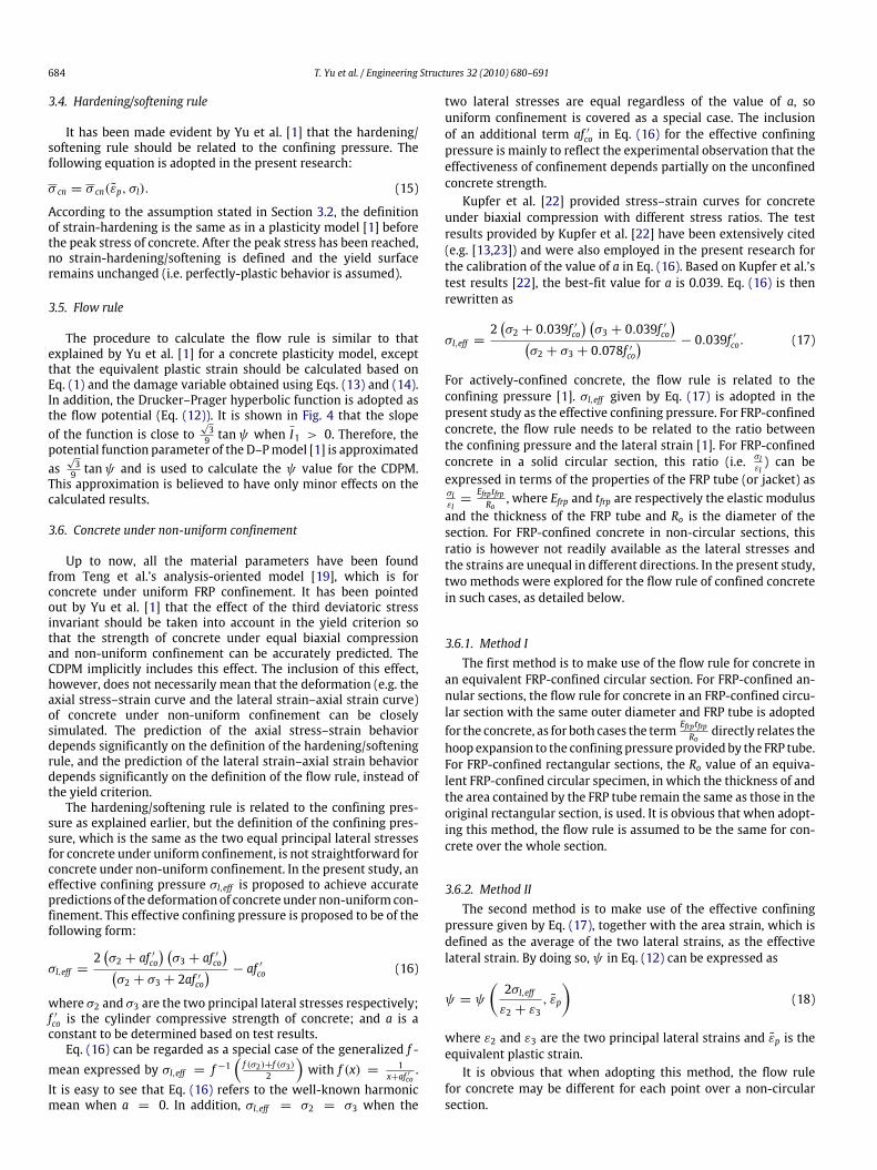
3.6. Concrete under non-uniform confinement
Up to now, all the material parameters have been foundfrom Teng et al.’s analysis-oriented model [19], which is forconcrete under uniform FRP confinement. It has been pointedout by Yu et al. [1] that the effect of the third deviatoric stressinvariant should be taken into account in the yield criterion sothat the strength of concrete under equal biaxial compressionand non-uniform confinement can be accurately predicted. TheCDPM implicitly includes this effect. The inclusion of this effect,however, does not necessarily mean that the deformation (e.g. theaxial stress–strain curve and the lateral strain–axial strain curve)of concrete under non-uniform confinement can be closelysimulated. The prediction of the axial stress–strain behaviordepends significantly on the definition of the hardening/softeningrule, and the prediction of the lateral strain–axial strain behaviordepends significantly on the definition of the flow rule, instead ofthe yield criterion.The hardening/softening rule is related to the confining pres-
sure as explained earlier, but the definition of the confining pres-sure, which is the same as the two equal principal lateral stressesfor concrete under uniform confinement, is not straightforward forconcrete under non-uniform confinement. In the present study, aneffective confining pressure σl,eff is proposed to achieve accuratepredictions of the deformation of concrete under non-uniformcon-finement. This effective confining pressure is proposed to be of thefollowing form:
σl,eff =2(σ2 + af ′co
) (σ3 + af ′co
)(σ2 + σ3 + 2af ′co
) − af ′co (16)
where σ2 and σ3 are the two principal lateral stresses respectively;f ′co is the cylinder compressive strength of concrete; and a is aconstant to be determined based on test results.Eq. (16) can be regarded as a special case of the generalized f -
mean expressed by σl,eff = f −1(f (σ2)+f (σ3)
2
)with f (x) = 1
x+af ′co.
It is easy to see that Eq. (16) refers to the well-known harmonicmean when a = 0. In addition, σl,eff = σ2 = σ3 when the
two lateral stresses are equal regardless of the value of a, souniform confinement is covered as a special case. The inclusionof an additional term af ′co in Eq. (16) for the effective confiningpressure is mainly to reflect the experimental observation that theeffectiveness of confinement depends partially on the unconfinedconcrete strength.Kupfer et al. [22] provided stress–strain curves for concrete
under biaxial compression with different stress ratios. The testresults provided by Kupfer et al. [22] have been extensively cited(e.g. [13,23]) and were also employed in the present research forthe calibration of the value of a in Eq. (16). Based on Kupfer et al.’stest results [22], the best-fit value for a is 0.039. Eq. (16) is thenrewritten as
σl,eff =2(σ2 + 0.039f ′co
) (σ3 + 0.039f ′co
)(σ2 + σ3 + 0.078f ′co
) − 0.039f ′co. (17)
For actively-confined concrete, the flow rule is related to theconfining pressure [1]. σl,eff given by Eq. (17) is adopted in thepresent study as the effective confining pressure. For FRP-confinedconcrete, the flow rule needs to be related to the ratio betweenthe confining pressure and the lateral strain [1]. For FRP-confinedconcrete in a solid circular section, this ratio (i.e. σl
εl) can be
expressed in terms of the properties of the FRP tube (or jacket) asσlεl=EfrptfrpRo, where Efrp and tfrp are respectively the elastic modulus
and the thickness of the FRP tube and Ro is the diameter of thesection. For FRP-confined concrete in non-circular sections, thisratio is however not readily available as the lateral stresses andthe strains are unequal in different directions. In the present study,two methods were explored for the flow rule of confined concretein such cases, as detailed below.
3.6.1. Method IThe first method is to make use of the flow rule for concrete in
an equivalent FRP-confined circular section. For FRP-confined an-nular sections, the flow rule for concrete in an FRP-confined circu-lar section with the same outer diameter and FRP tube is adoptedfor the concrete, as for both cases the term Efrptfrp
Rodirectly relates the
hoop expansion to the confining pressure provided by the FRP tube.For FRP-confined rectangular sections, the Ro value of an equiva-lent FRP-confined circular specimen, in which the thickness of andthe area contained by the FRP tube remain the same as those in theoriginal rectangular section, is used. It is obvious that when adopt-ing this method, the flow rule is assumed to be the same for con-crete over the whole section.
3.6.2. Method IIThe second method is to make use of the effective confining
pressure given by Eq. (17), together with the area strain, which isdefined as the average of the two lateral strains, as the effectivelateral strain. By doing so, ψ in Eq. (12) can be expressed as
ψ = ψ
(2σl,effε2 + ε3
, ε̃p
)(18)
where ε2 and ε3 are the two principal lateral strains and ε̃p is theequivalent plastic strain.It is obvious that when adopting this method, the flow rule
for concrete may be different for each point over a non-circularsection.

T. Yu et al. / Engineering Structures 32 (2010) 680–691 685
Fig. 5. FE model for hybrid DSTCs.
4. Numerical verification
4.1. Finite element modeling
Comparisons between FE predictions obtained using the pro-posed constitutive model and test results are presented in thissection for actively-confined concrete, concrete under biaxial com-pression, and FRP-confined concrete in circular section and rectan-gular sections as well in hybrid DSTCs with an annular section.For the two cases of concrete under biaxial compression
and a uniform active confining pressure, only a single 8-nodesolid element was employed in the numerical analysis. For FRP-confined columns, although the two ends of a short column wereconstrained by the loading platens in the test, these constraintswere assumed to have little effects on the behavior in the mid-height region of the column with a length equal to twice thediameter. Consequently, for both FRP-confined square and circularconcrete specimens, the FE model included only one-fourth ofa vertical slice of the specimen and consisted of a single layerof 8-node solid elements for the concrete tied to 4-node shellelements for the FRP jacket (see Fig. 11). For hybrid DSTCs (Fig. 1),the FE model employed consisted of one layer of finite elementsspanning a one-degree circumferential segment (Fig. 5). The finiteelement model was assigned boundary conditions representingaxis-symmetric behavior (Fig. 5). These simple models wereemployed to provide predictions of the behavior of the mid-heightregion of columns.For FRP-confined columns, the FRP tube was assumed to be-
have in a linear elastic manner with stiffness in the hoop direc-tion only. For hybrid DSTCs, the average stress–strain curve of thesteel from tensile tests was represented with a number of datapoints. The well-known J2 flow theory was employed to modelthe plastic behavior of the steel. The concrete was modeled by themodified CDPM presented in the preceding sections. The predictedcurves are terminatedwhen the experimental ultimate hoop strainis reached.For FRP-confined columns, the Mesh Tie Constraint option of
ABAQUS was adopted in the model to simulate the interaction be-tween the FRP and the concrete. Using these constraints, a node onthe FRP tube was tied to a corresponding node on the outer edge ofthe concrete infill so that the two nodes were forced to experiencethe same translations. For hybrid DSTCs, the Contact Pairs option ofABAQUSwas adopted to simulate the interaction between the steeltube and the concrete. In the radial direction, the so-called ‘‘hard’’contact, which allows the two surfaces to separate fromeach other,was specified. The contact pressure was automatically calculatedby the program when the two surfaces were in contact. On thecontrary, if the surfaces were not in contact, the pressure becamezero. In the tangential direction, a friction coefficient was speci-fied but this friction coefficient was not expected to affect the pre-dictions as no slips were expected between the steel tube and theconcrete infill due to the axis-symmetric nature of the FE model.Mesh convergence studies were conducted for each type of FRP-confined columns, arriving at appropriate meshes which providedalmost the same axial stress–strain curves as those from furtherrefined meshes.
4.2. Actively-confined concrete
Fig. 6 shows a comparison between the predictions obtainedfrom the FE model and the test results reported by Sfer et al. [24]for actively-confined concrete. The concrete had an unconfinedstrength of 32.8 MPa and a corresponding strain of 0.0018, andwas confined by a constant pressure of 9 MPa. Predictions fromTeng et al.’s analysis-oriented model [19] are also shown in Fig. 6for reference. It is evident that the FE analysis provides almost thesame predictions as Teng et al.’s model [19], and the predictions ofbothmodels are reasonably close to the experimental stress–straincurve. The minor difference in the lateral–axial strain curve be-tween the FE results and the predictions of Teng et al.’s model [19]is due to the limitation of the allowable values of ψ in the CDPMin ABAQUS. The allowable values of ψ are limited between 0◦ and56◦ in ABAQUS, while the ψ value calculated from Teng et al.’smodel [19] for use in the proposed model is negative in the earlyloading stage. In order to make use of the theoretical frameworkof the CDPMmodel in ABAQUS, the negative values were replacedwith 0◦ in the implementation. This consequently caused a smalloverestimation of the lateral strain in the early loading stage.
4.3. Concrete under biaxial compression
Fig. 7 shows a comparison between the FE results and the re-sults of biaxial compression tests by Kupfer et al. [22]. The concretehad a uniaxial compressive strength of 32.0MPa and a correspond-ing strain of 0.0021, andwas subjected to biaxial compressionwithtwo different axial-to-lateral stress ratios, namely, σ1/σ2 = 1 and0.5 respectively. Fig. 7 shows that the FE results agreewell with thetest results.
4.4. FRP-confined circular concrete column
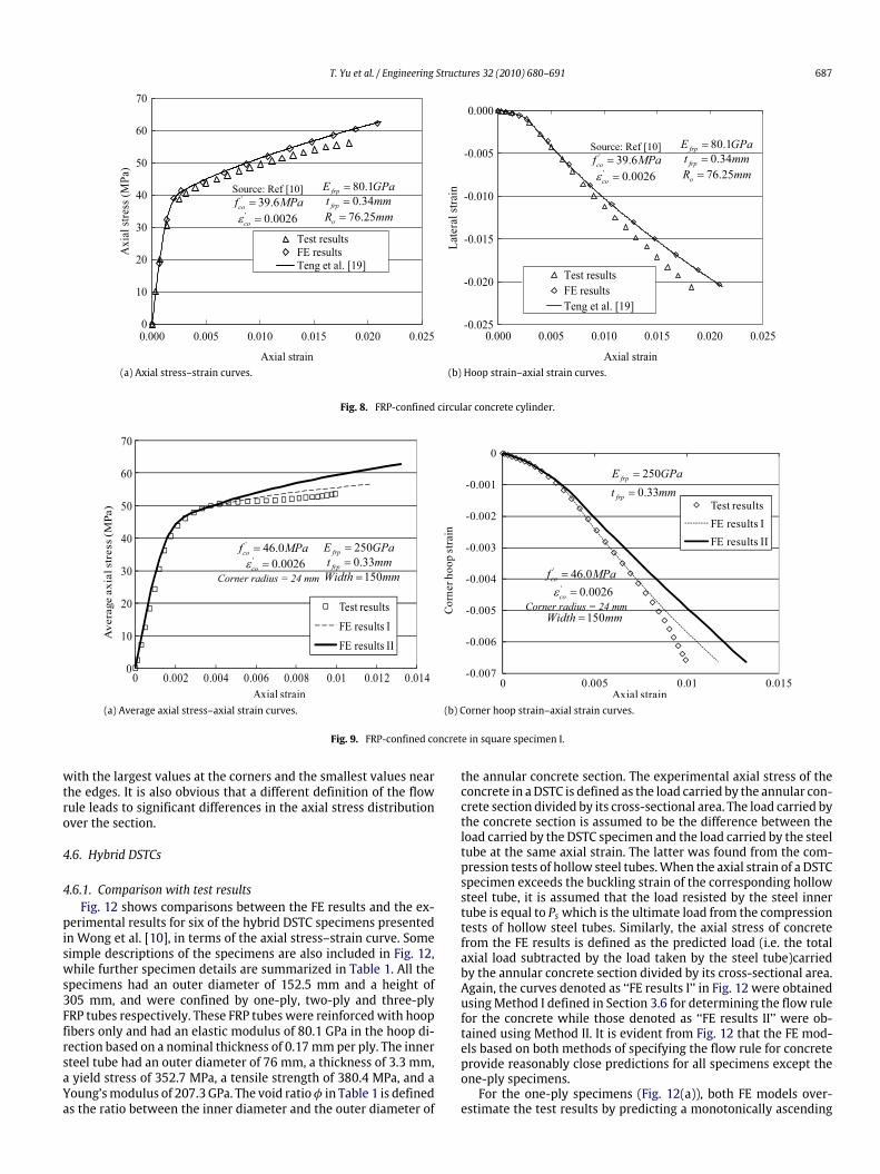
Fig. 8 shows a comparison between the predictions of the FEmodel and the test results of an FRP-confined circular concretecolumn tested by Wong et al. [10]. The concrete in this specimenhad an unconfined strength of 39.6MPa and a corresponding strainof 0.00263. The cylinder had a diameter of 152.5 mm and a heightof 305mm, andwas confined by a two-ply FRP tube with an elasticmodulus of 80.1 GPa based on a nominal thickness of 0.17 mmper ply. As the concrete is subjected to uniform confinement inthis case, there is no difference between Method I and Method IIin specifying the flow rule of concrete. Results from Teng et al.’sanalysis-oriented model [19] are also shown for reference. The FEresults are almost the same as the predictions from Teng et al.’smodel [19], and the results frombothmethods are reasonably closeto the test stress–strain curve (the three curves are almost identicaland the error in the concrete strength is around 10%).
4.5. FRP-confined square concrete columns
4.5.1. Comparison with test resultsFigs. 9 and 10 show comparisons between the FE predictions
and the test results for two FRP-confined square concrete columns.

686 T. Yu et al. / Engineering Structures 32 (2010) 680–691
(a) Axial stress–strain curves. (b) Axial stress–lateral strain curves.
(c) Lateral strain–axial strain curves.
Fig. 6. Actively-confined concrete.
Fig. 7. Concrete under biaxial compression.
The test results shown in Fig. 9 are for a square specimen (Spec-imen I) with an unconfined concrete strength of 46.0 MPa and acorresponding strain of 0.0026 tested at The Hong Kong Polytech-nic University (PolyU). The specimen had a width of 150 mm, withthe four corners rounded into a radius of 24 mm. It was wrappedwith a two-ply carbon fiber-reinforced polymer (CFRP) jacket withan elasticmodulus of 250,000MPa based on a nominal thickness of0.165 mm per ply. The test results shown in Fig. 10 are for anothersquare specimen (Specimen II) tested at PolyU with an uncon-
fined concrete strength of 37.5 MPa and a corresponding strain of0.0031. The specimenhad awidth of 150mm,with the four cornersrounded into a radius of 25 mm. It was wrapped with a three-plyglass fiber-reinforced polymer (GFRP) jacket with an elastic modu-lus of 80,100MPa based on a nominal thickness of 0.17mmper ply.The comparisons are for both the average axial stress–axial straincurve and the corner hoop strain–axial strain curve. The averageaxial stress is defined as the load divided by the cross-sectionalarea of the concrete. The experimental corner hoop strains wereaveraged from the readings of four strain gauges at the centers ofthe four corners. The curves denoted as ‘‘FE results I’’ in Figs. 9 and10were obtained by usingMethod I explained in Section 3.6 for theflow rule of concretewhile those denoted as ‘‘FE results II’’ were ob-tained by usingMethod II for the flow rule. Figs. 9 and 10 show thatthe predictions are in reasonably close agreement with the test re-sults in terms of the average axial stress–strain curve, regardless ofthemethod used to define the flow rule. Method I led to closer pre-dictions in terms of the corner hoop strain–axial strain curve, thusleading to more accurate predictions for the ultimate state (the er-rors in the concrete strength is within 10%).
4.5.2. Stress variations over the sectionFig. 11 shows the predicted axial stress distributions over the
section for Specimen I, obtained using the two methods for speci-fying the flow rule respectively. The negative values of S33 in thelegend box are the axial compressive stresses. It is obvious fromFig. 11 that the axial stress varies significantly over the section,
T. Yu et al. / Engineering Structures 32 (2010) 680–691 687
(a) Axial stress–strain curves. (b) Hoop strain–axial strain curves.
Fig. 8. FRP-confined circular concrete cylinder.
(a) Average axial stress–axial strain curves. (b) Corner hoop strain–axial strain curves.
Fig. 9. FRP-confined concrete in square specimen I.
with the largest values at the corners and the smallest values nearthe edges. It is also obvious that a different definition of the flowrule leads to significant differences in the axial stress distributionover the section.
4.6. Hybrid DSTCs
4.6.1. Comparison with test resultsFig. 12 shows comparisons between the FE results and the ex-
perimental results for six of the hybrid DSTC specimens presentedin Wong et al. [10], in terms of the axial stress–strain curve. Somesimple descriptions of the specimens are also included in Fig. 12,while further specimen details are summarized in Table 1. All thespecimens had an outer diameter of 152.5 mm and a height of305 mm, and were confined by one-ply, two-ply and three-plyFRP tubes respectively. These FRP tubes were reinforcedwith hoopfibers only and had an elastic modulus of 80.1 GPa in the hoop di-rection based on a nominal thickness of 0.17mmper ply. The innersteel tube had an outer diameter of 76 mm, a thickness of 3.3 mm,a yield stress of 352.7 MPa, a tensile strength of 380.4 MPa, and aYoung’smodulus of 207.3 GPa. The void ratioφ in Table 1 is definedas the ratio between the inner diameter and the outer diameter of
the annular concrete section. The experimental axial stress of theconcrete in aDSTC is defined as the load carried by the annular con-crete section divided by its cross-sectional area. The load carried bythe concrete section is assumed to be the difference between theload carried by the DSTC specimen and the load carried by the steeltube at the same axial strain. The latter was found from the com-pression tests of hollow steel tubes.When the axial strain of a DSTCspecimen exceeds the buckling strain of the corresponding hollowsteel tube, it is assumed that the load resisted by the steel innertube is equal to Ps which is the ultimate load from the compressiontests of hollow steel tubes. Similarly, the axial stress of concretefrom the FE results is defined as the predicted load (i.e. the totalaxial load subtracted by the load taken by the steel tube)carriedby the annular concrete section divided by its cross-sectional area.Again, the curves denoted as ‘‘FE results I’’ in Fig. 12 were obtainedusingMethod I defined in Section 3.6 for determining the flow rulefor the concrete while those denoted as ‘‘FE results II’’ were ob-tained using Method II. It is evident from Fig. 12 that the FE mod-els based on both methods of specifying the flow rule for concreteprovide reasonably close predictions for all specimens except theone-ply specimens.For the one-ply specimens (Fig. 12(a)), both FE models over-
estimate the test results by predicting a monotonically ascending

688 T. Yu et al. / Engineering Structures 32 (2010) 680–691
(a) Average axial stress–axial strain curves. (b) Corner hoop strain–axial strain curves.
Fig. 10. FRP-confined concrete in square specimen II.
(a) Flow rule based on Method I. (b) Flow rule based on Method II.
Fig. 11. Axial stress distributions over the section.
curve. This overestimation is believed to be due to Teng et al.’sanalysis-orientedmodel [19] whichwas adopted to producemate-rial parameters for the constitutive model. Teng et al. [19] pointedout that although their model provided accurate predictions fornumerous independent tests of FRP-confined concrete, it mightoverestimate the axial resistance of concrete confined by a weakFRP jacket (such as a one-ply FRP jacket herein).The FE results indicate that for such DSTC sections subjected to
axial compression, the steel tube and the concrete are in contactin the beginning as the initial Poisson’s ratio of concrete is smallerthan that of steel but later separate from each other as the dilationof concrete increases. The two components come into contact againlater if the FRP tube is sufficiently stiff. Such third-stage interactionwas predicted by the FE models to occur only for specimensD40-B3. This interaction explains the difference in the predictedstress–strain curve using the two methods for specifying the flowrule for concrete. For specimens D40-B3, the curve predicted usingMethod II becomes higher in the late stage as the interactionbetween the concrete and the steel tube was predicted to beginat a smaller axial strain than that predicted using Method I. Whenusing Method I, such interaction was predicted to begin at an axialstrain slightly beyond the experimental ultimate strain.Fig. 13 shows comparisons between the FE and the experimen-
tal results, in termsof thehoop strain–axial strain curve. The exper-imental strains were obtained from several strain rosettes located
Table 1Details of DSTC specimens tested by Wong et al. [10].
Specimen FRP outertubethickness
Void diameter(mm) (voidratio φ)
Steel tubediameter Do(thickness t)(mm)
Concretecylinderstrengthf ′co (MPa)
D40-B1-I,II
1 ply76 (0.50) 76 (3.3) 39.6
D40-B2-I,II
2 plies
D40-B3-I,II
3 plies
at the mid-height of the outer FRP tube. The predictions are seento be in close agreement with all test results.
4.6.2. Stress variations in the radial directionFig. 14 shows the predicted axial stress distributions in the ra-
dial direction for Specimen D37-B2-I using the two differentmeth-ods for specifying the flow rule for concrete. It is again obvious that,although a different definition of the flow rule makes only smalldifferences in the predicted axial stress–strain curve and hoopstrain–axial strain curve (Figs. 12 and 13), it leads to significantdifferences in the axial stress distribution over the section. WhenMethod II is used to define the flow rule, the stress variation ismore

T. Yu et al. / Engineering Structures 32 (2010) 680–691 689
(a) Void ratio = 0.5, f ′co = 39.6 MPa, one-ply FRP tube. (b) Void ratio= 0.5, f ′co = 39.6 MPa, two-ply FRP tube.
(c) Void ratio= 0.5, f ′co = 39.6 MPa, three-ply FRP tube.
Fig. 12. Axial stress–strain curves of concrete in DSTCs.
rapid near the inner edge but slower near the outer edge, comparedwith the results obtained on usingMethod I. It is also obvious fromFig. 14 that the axial stress varies significantly in the radial direc-tion. The axial stress reduceswith the distance from the outer edge,and the rate of variation is more significant near the inner edge.This could be explained by the fact that the two lateral stressesare more non-uniform near the inner edge, leading to a smaller ef-fective confining stress and a less significant confining effect. Theability to predict stress variations over the section is one of the ad-vantages of a three-dimensional FE model over a one-dimensionalanalysis-oriented model such as Teng et al.’s model [19].
5. Conclusions
This paper has presented a modified plastic-damage modelwithin the theoretical framework of the Concrete Damaged Plas-ticity Model (CDPM) in ABAQUS [16] for the modeling of con-fined concrete. The modifications proposed for the CDPM includea damage parameter, a strain-hardening/softening rule and a flowrule, all of which are confinement-dependent, and a pressure-dependent yield criterion. The distinct characteristics of non-uniformly confined concrete are also included in this model bydefining an effective confining pressure. Two methods of defin-ing the flow rule are proposed for non-uniformly confined con-crete; the first method is simpler while the second method
appears to be more reasonable in that it takes into account thedifference in the flow rule between different points over a non-circular section. Finite elementmodels incorporating the proposedCDPM model were developed for concrete in a number of stressstates, including active confinement, biaxial compression, FRP-confined circular and square columns, and hybrid DSTCs [11]. FEpredictions, obtained using either method for the definition of theflow rule for concrete, have been found to be in close agreementwith existing test results in terms of the overall behavior, includ-ing the axial stress–strain behavior and the hoop strain–axial strainbehavior. The differences due to these two different methods liemainly in the axial stress distribution.Despite the close agreement between the FE and the test re-
sults, it is important to note that while the proposed constitutivemodel has a rigorous basis for uniformly-confined concrete (con-fined concrete in solid circular sections), it needs to rely on certainassumptions derived from empirical evidence for confined con-crete in non-circular sections, particularly in the specification ofthe flow rule. Nevertheless, the present CDPM model still repre-sents an important improvement to existing approaches for mod-eling FRP-confined concrete in non-circular sectionswhich is basedon the assumption of either a constant potential function param-eter (e.g. [25,26]) or potential function parameters that imply vol-ume compaction of concrete throughout the deformation process

690 T. Yu et al. / Engineering Structures 32 (2010) 680–691
(a) Void ratio= 0.5, f ′co = 39.6 MPa, one-ply FRP tube. (b) Void ratio= 0.5, f ′co = 39.6 MPa, two-ply FRP tube.
(c) Void ratio= 0.5, f ′co = 39.6 MPa, three-ply FRP tube.
Fig. 13. Hoop strain–axial strain curves of concrete in DSTCs.
(a) Flow rule based on Method I. (b) Flow rule based on Method II.
Fig. 14. Axial stress distributions in the radial direction.
(e.g. [27]). In the review process of the present paper, Karabi-nis et al. [28] published a study in which they varied the po-tential function parameter with the FRP jacket stiffness in theirFE model. However, their model still suffers from the following
shortcomings: (a) the characteristics of FRP-confined concrete isonly partially reflected [1]; (b) the variation of the potential func-tion parameter with the plastic strain is not accounted for; (c) theshear strength ratio adopted is higher than experimental values;

T. Yu et al. / Engineering Structures 32 (2010) 680–691 691
(d) the hardening/softening rule was derived from the uniaxialstress–strain curve of unconfined concrete, which leads to under-estimation of the stress in the confined concrete [1]. The presentCDPM model, however, have appropriately addressed all these is-sues. A thorough discussion of the existing approaches presentedin [25–28] is given the companion paper [1]. Clearly, further re-search is still needed to verify the proposed model more fully andto enhance the theoretical rigor of the model. The proposed modelcan also be very usefully exploited in FE models to investigate thebehavior of confined concrete in various forms of columns to de-velop a better understanding of structural behavior and to developdesign methods for practical use.
Acknowledgements
The authors are grateful for the financial support fromTheHongKong Polytechnic University (Project Codes: RG7E and BBZH) andthe Natural Science Foundation of China (Project No. 50329802).
References
[1] Yu T, Teng JG, Wong YL, Dong SL. Finite element modeling of confinedconcrete-I: Drucker–Prager type plasticity model. Eng Struct 2010;32(3):665–79.
[2] Lam L, Teng JG. Design-oriented stress–strainmodel for FRP-confined concretein rectangular columns. J Reinf Plast Compos 2003;22(13):1149–86.
[3] Chaallal O, HassanM, ShahawyM. Confinementmodel for axially loaded shortrectangular columns strengthened with fiber-reinforced polymer wrapping.ACI Struct J 2003;100(2):215–21.
[4] Wu G, Wu ZS, Lu ZT. Design-oriented stress–strain model for concrete prismsconfined with FRP composites. Constr Build Mater 2007;21:1107–21.
[5] Sheikh SA, Li Y. Design of FRP confinement for square concrete columns. EngStruct 2007;29(6):1074–83.
[6] Wang LM,Wu YF. Effect of corner radius on the performance of CFRP-confinedsquare concrete columns: Test. Eng Struct 2008;30(2):493–505.
[7] Teng JG, Lam L. Compressive behaviour of carbon fiber reinforced polymer-confined concrete in elliptical columns. J Struct Eng ASCE 2002;128(12):1535–43.
[8] Fam AZ, Rizkalla SH. Confinement model for axially loaded concrete confinedby circular fiber-reinforced polymer tubes. ACI Struct J 2001;98(4):451–61.
[9] Becque J, Patnaik AK, Rizkalla SH. Analyticalmodels for concrete confinedwithFRP tubes. J Compos Constr, ASCE 2003;7(1):1–8.
[10] Wong YL, Yu T, Teng JG, Dong SL. Behavior of FRP-confined concrete in annularsection columns. Compos Part B-Eng 2008;39(3):451–66.
[11] Teng JG, Yu T, Wong YL, Dong SL. Hybrid FRP-concrete-steel tubular columns:Concept and behavior. Constr Build Mater 2007;21(4):846–54.
[12] Teng JG, Lam L. Behavior and modeling of FRP-confined concrete. J Struct Eng,ASCE 2004;130(11):1713–23.
[13] Maekawa K, Pimanmas A, Okamura H. Nonlinear mechanics of reinforcedconcrete. Spon Press; 2003.
[14] Contrafatto L, Cuomo M. A framework of elastic–plastic damaging model forconcrete under multiaxial stress states. Int J Plast 2006;22:2272–300.
[15] Oshima M, Hashimoto C. Mechanical properties of concrete confined by steelrings. In: Summaries of the 39th annual convention, vol. V. Japan Society ofCivil Engineers; 1984.
[16] ABAQUS. ABAQUS Analysis user’s manual, version 6.5. 2004.[17] Lubliner J, Oliver J, Oller S, Onate E. A plastic-damage model for concrete. Int J
Solid Struct 1989;25:299–329.[18] Lee J, Fenves GL. Plastic-damage model for cyclic loading of concrete
structures. J Eng Mech, ASCE 1998;124(8):892–900.[19] Teng JG, Huang YL, Lam L, Ye LP. Theoretical model for fiber reinforced
polymer-confined concrete. J Compos Constr, ASCE 2007;11(2):201–10.[20] Murray YD, Lewis BA. Numerical simulation of damage in concrete. APTEK
technical report to the Defense Nuclear Agency, Contract No. DNA001-91-C-0075. Report No. DNA-TR-94-190. 1995.
[21] Schwer L. Geomaterial modeling with LS-DYNA. Short course notes, organizedby Livermore Software Technology Corporation, 2003.
[22] Kupfer H, Hilsdorf HK, Rusch H. Behavior of concrete under biaxial stresses.ACI J 1969;66:656–66.
[23] Ahmad SH, Shah SP. Complete triaxial stress–strain curves for concrete. J StructDiv, ASCE 1982;108(ST4):728–42.
[24] Sfer D, Carol I, Gettu R, Etse G. Study of the behavior of concrete under triaxialcompression. J Eng Mech, ASCE 2002;128(2):156–63.
[25] MirmiranA, Zagers K, YuanWQ.Nonlinear finite elementmodeling of concreteconfined by fiber composites. Finite Elem Anal Des 2000;35:79–96.
[26] Rousakis TC, Karabinis AI, Kiousis PD. FRP-confined concrete members:Axial compression experiments and plasticity modeling. Eng Struct 2007;29:1343–53.
[27] Karabinis AI, Rousakis TC. Concrete confined by FRP material: A plasticityapproach. Eng Struct 2002;24:923–32.
[28] Karabinis AI, Rousakis TC, Manolitsi GE. 3D finite-element analysis ofsubstandard RC columns strengthened by fiber-reinforced polymer sheets.J Compos Constr ASCE 2008;12(5):531–40.