FINITE ELEMENT MODEL FOR THE EFFECT OF HEAT … · we can find some attempts to reduce modelling...
14
Int. J. Mech. Eng. & Rob. Res. 2014 Harshal B Sonawane and Eknath R Deore, 2014 ISSN 2278 – 0149 www.ijmerr.com V , 2014 © 2014 IJMERR. All Rights Reserved Research Paper FINITE ELEMENT MODEL FOR THE EFFECT OF HEAT INPUT & SPEED ON RESIDUAL STRESS DURING WELDINGS Harshal B Sonawane 1 * and Eknath R Deore 2 *Corresponding Author: Harshal B Sonawane [email protected] This report is a presentation of ANSYS FE models for the thermal and mechanical welding simulation. To develop suitable welding models, we must consider the process parameter (welding speed, Heat flux, Gap and Temperature), the geometrical constraints, the material nonlinearities and all physical phenomena involved in welding. Therefore it is a great challenge to consider all factors at the same time, so generally the models include some approximations: in the works, we can find some attempts to reduce modelling efforts, and Reduces Residual stress in welding. Keywords: ANSYS FE model, Welding speed, Heat flux, Gap, Temperature INTRODUCTION The welding process is an integral manu- facturing procedure in many engineering and structural component, having a direct influ- ence on the integrity of the components and their thermal and mechanical behaviour during service. Due to the high temperature introduced during welding and subsequent cooling of weld metal, welding can produce undesirable residual stress and the defor- mation on the component due to rupture of the welded joints. It is important interest to simulate the process of welding to delineate the ensuring the residual stress and defor- mation and predict the behaviour of welded 1 Research Scholar Mechanical Engineering Department SSVPS COE Dhule, SSVPS COE, DHULE-424001. 2 Professor and Head of Mechanical Engineering Department SSVPS COE Dhule, SSVPS COE, DHULE-424001. structures. Some of the other identified effects are as Shrinkage, Inclusions, Segre- gation, Porosity, Surface defects. Reduces Residual stress in welding. The present work deals with the following main assumptions and features about the thermal model: a) The displacements of the parts, during the welding, do not affect the thermal distribution of the parts themselves b) All the material properties are described till to the liquid phase of metal c) Convection and radiation effects are considered d) TIG methodologies for root and/or filling weld are modelled ol. 3, No. 3, July
Transcript of FINITE ELEMENT MODEL FOR THE EFFECT OF HEAT … · we can find some attempts to reduce modelling...
763
Int. J. Mech. Eng. & Rob. Res. 2014 Harshal B Sonawane and Eknath R Deore, 2014
ISSN 2278 – 0149 www.ijmerr.com
V , 2014
© 2014 IJMERR. All Rights Reserved
Research Paper
FINITE ELEMENT MODEL FOR THE EFFECT OF
HEAT INPUT & SPEED ON RESIDUAL STRESS
DURING WELDINGS
Harshal B Sonawane1* and Eknath R Deore2
*Corresponding Author: Harshal B Sonawane � [email protected]
This report is a presentation of ANSYS FE models for the thermal and mechanical weldingsimulation. To develop suitable welding models, we must consider the process parameter (weldingspeed, Heat flux, Gap and Temperature), the geometrical constraints, the material nonlinearitiesand all physical phenomena involved in welding. Therefore it is a great challenge to consider allfactors at the same time, so generally the models include some approximations: in the works,we can find some attempts to reduce modelling efforts, and Reduces Residual stress in welding.
Keywords: ANSYS FE model, Welding speed, Heat flux, Gap, Temperature
INTRODUCTION
The welding process is an integral manu-facturing procedure in many engineering andstructural component, having a direct influ-ence on the integrity of the components andtheir thermal and mechanical behaviourduring service. Due to the high temperatureintroduced during welding and subsequentcooling of weld metal, welding can produceundesirable residual stress and the defor-mation on the component due to rupture ofthe welded joints. It is important interest tosimulate the process of welding to delineatethe ensuring the residual stress and defor-mation and predict the behaviour of welded
1 Research Scholar Mechanical Engineering Department SSVPS COE Dhule, SSVPS COE, DHULE-424001.2 Professor and Head of Mechanical Engineering Department SSVPS COE Dhule, SSVPS COE, DHULE-424001.
structures. Some of the other identifiedeffects are as Shrinkage, Inclusions, Segre-gation, Porosity, Surface defects. ReducesResidual stress in welding. The present workdeals with the following main assumptionsand features about the thermal model:
a) The displacements of the parts, duringthe welding, do not affect the thermaldistribution of the parts themselves
b) All the material properties are describedtill to the liquid phase of metal
c) Convection and radiation effects areconsidered
d) TIG methodologies for root and/or fillingweld are modelled
ol. 3, No. 3, July
764
Int. J. Mech. Eng. & Rob. Res. 2014 Harshal B Sonawane and Eknath R Deore, 2014
e) The ANSYS birth and death procedureis used and the CPU time was stronglyreduced
TYPES OF WELDED JOINTS
The welding joints are also different types like
i. Fillet-joint
ii. Butt joint
iii. Lap joint
Fillet Joint
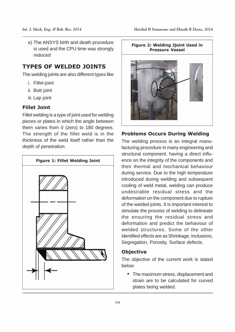
Fillet welding is a type of joint used for weldingpieces or plates in which the angle betweenthem varies from 0 (zero) to 180 degrees.The strength of the fillet weld is in thethickness of the weld itself rather than thedepth of penetration.
Figure 1: Fillet Welding Joint
Figure 2: Welding Jjoint Used inPressure Vessel
Problems Occurs During Welding
The welding process is an integral manu-facturing procedure in many engineering andstructural component, having a direct influ-ence on the integrity of the components andtheir thermal and mechanical behaviourduring service. Due to the high temperatureintroduced during welding and subsequentcooling of weld metal, welding can produceundesirable residual stress and thedeformation on the component due to ruptureof the welded joints. It is important interest tosimulate the process of welding to delineatethe ensuring the residual stress anddeformation and predict the behaviour ofwelded structures. Some of the otheridentified effects are as Shrinkage, Inclusions,Segregation, Porosity, Surface defects.
Objective
The objective of the current work is statedbelow
• The maximum stress, displacement andstrain are to be calculated for curvedplates being welded.
765
Int. J. Mech. Eng. & Rob. Res. 2014 Harshal B Sonawane and Eknath R Deore, 2014
• The deformation due to the temperaturevariation is to be calculated.
SCOPE OF PAPER
The scope of this study is as follows
• The material selected is AISI stainlesssteel.
• The effect of temperature is only to bestudied.
• The considered case of the plate iscurved plates.
• The material properties are adoptedfrom previous studies carried out in thesame area.
Cad Modeling for Welding Plate
In this case CAD modelling of curved platesis described using Solid Works. The SolidWorks application is mechanical designautomation software that takes advantage ofthe familiar Microsoft Windows graphical userinterface. This easy-to-learn tool makes itpossible for mechanical designers to quicklysketch ideas, experiment with features anddimensions, and produce models anddetailed drawings. SolidWorks is a 3Dmechanical CAD (computer-aided design)program that runs on Microsoft Windows andis developed by Dassault Systems. It integra-tes a broad range of mechanical CAD, designvalidation, product data management, designcommunication, and CAD productivity toolsin a single, affordable easy to use package.One can go from concept to virtual prototypefaster than ever thought possible with thedesired quality using a single easy to useapplication. Solid Works is so complete thatone can progress from a product concept toa highly accurate virtual prototype without
employing any other software. Figure 3shows typical user interface of SolidWorks.
• A SolidWorks model consists of 3D solidgeometry in a part or assemblydocument.
• Drawings are created from models, orby drafting views in a drawingdocument.
• Typically, you begin with a sketch,create a base feature, and then addmore features to your model. (You canalso begin with an imported surface orsolid geometry.)
• You can refine your design by adding,editing, or reordering features.
• Associatively between parts,assemblies, and drawings assures thatchanges made to one document orviews are automatically made to allother documents and views.
• You can generate drawings or assem-blies at any time in the design process.
• With a Rear-view-compatible graphicscard installed, you can display photo-realistic models and environments.
• Click Tools, Options on the main menuto display System Options and Docu-ment Properties.
• The Solid Works software saves yourwork for you with auto-recover. You canalso choose to be reminded to saveyour work.
Finite Element Analysis of Welding
Plate
The FEM is one such approximate solutiontechnique. The FEM is a numerical procedurefor obtaining approximate solutions to many

766
Int. J. Mech. Eng. & Rob. Res. 2014 Harshal B Sonawane and Eknath R Deore, 2014
problems encountered in engineering analy-sis. Mathematically, the structure to be analy-zed is subdivided into a mesh of finite sizedelements of simple shape. Within eachelement, the variation of displacement isassumed to be determined by simple linearor quadratic shape function & nodal displace-ments. For this the equations of equilibriumare assembled in a matrix form which can beeasily be programmed & solved on a compu-ter. After applying approximate boundaryconditions, nodal displacements are found bysolving the matrix stiffness equation. Oncethe nodal displacements are known, elementstresses & strains can be calculated. Forgetting the solution in FEM analysis step bystep procedure are required these procedureare mentioned below.
Present work uses ANSYS for FEManalysis of welding plate. ANSYS is widelyused FEM analysis software both inacademics as well as in industry. UsingANSYS one can perform various tasks of FEanalysis and there is huge element libraryavailable to meet the user requirements ofvarious type of analysis. There are twodifferent user interfaces available i.e. ANSYSclassic and ANSYS workbench. Traditionally,
ANSYS classic is choice of analysts but oflate ANSYS workbench is becoming popularwith analysts. Present work used ANSYSclassic version 14.2. After analysis, variousresults are reviewed such as stress, strainand deformation.
Figure 3: SolidWorks User Interface
FEA OF WELDING OF
CURVED PLATE
In the welding process high amount of heatis generated which causes change or defor-mation of the two parts being welded to-gether. Thus to carry out the analysis of theparts being welded as in this case the weldingof the curved plated both the thermal and thestructural analysis is needed to be carriedout. In this the major stresses are being gene-rated due to the temperature change and thedeformation occurs in the plates. Thus firstwe need to carry out the thermal analysis andthen the structural analysis must be carriedout.
Figure 4: Flow Chart of Steps inSoftware Analysis

767
Int. J. Mech. Eng. & Rob. Res. 2014 Harshal B Sonawane and Eknath R Deore, 2014
Figure 5: Model of the Curved Plate
Thermal Analysis
1. Generation of Model
Based on the dimensions of the curved plate,the model is created in the solid work, asshown in Figure 4.
2. Selection of Elements
The model is using two types of element i.e.,SOLID 70 and SHELL 131 (ANSYS elementlibrary). The details of the selected elementsare mentioned below.
i. Solid 70 (Brick 8 node 70)
SOLID70 has a 3-D thermal conductioncapability. The element has eight nodes witha single degree of freedom, temperature, ateach node. The element is applicable to a 3-D, steady-state ortransient thermal analysis.The element also can compensate for masstransport heat flow from a constant velocityfield.
ii. Shell 131(3 D 4node 131)
SHELL131 is a 3-D layered shell elementhaving in-plane and through-thicknessthermal conduction capability. The elementhas four nodes with up to 32 temperature
degrees of freedom at each node. Theconducting shell element is applicable to a3-D, steady-state or transient thermalanalysis. SHELL131 generates temperaturesthat can be passed to structural shellelements in order to model thermal bending.
Figure 7: Geometry of Shell 131 Element
Mesh
As mentioned above the solid 70 and shell131 element used. The meshing of the modelis done by using the hex shape elements. Inthese the fine meshing were done for gettingthe accuracy in the solution.
Figure 6: Geometry of Solid 70 Element

768
Int. J. Mech. Eng. & Rob. Res. 2014 Harshal B Sonawane and Eknath R Deore, 2014
Boundary Conditions for FEA
Due to the heat applied to the plate it getsliberated to the surrounding through the modeof convection. For that purpose the convec-tion were applied to the plate as the boundarycondition.
Load
For obtaining the effect of the welding tempe-rature the heat flux is applied as load on thewelded curved plate model.
Structural Analysis
To carry out the structural analysis thethermal profile obtained in the Table 1 is takenas loads acting on the welded plates. Thusthe need of material properties and otherrelevant details get avoided.
Boundary Condition
The Figure 10 shows the application of theboundary conditions to the model. Thedisplacement at both the end of the plate iszero i.e. Ux= Uy=Uz= 0.
Figure 9: Boundary Condition Applied tothe Thermal Welded Plates
Load
The temperature profile obtained from thethermal analysis is taken as the load for thestructural analysis
Solution
After applying the load there is need to checkthe deformation, stress, strain occurred onthe curved plate for that purpose in ANSYSthe solution step is employed.
Figure 8: Meshing of the Welded Plates
Figure 10: Boundary Condition Appliedto the Structural Welded Plates

769
Int. J. Mech. Eng. & Rob. Res. 2014 Harshal B Sonawane and Eknath R Deore, 2014
Post Processing
In post processing the effect of welding interms of displacement, stress, strains werefound out. For the further results the heat fluxand the speed were varied.
RESULTS AND DISSCUTION
Effect of Process Parameter on
Welding
In this work, two cases with different combi-nations of parameters have been studied.
The two cases are as described in Table 1below. Each parameter was investigated withlow, medium, and high values of heat fluxand speed.
Table 1: Changing Parameter ofHeat Flux and Speed
Case
1
2
Study
Effect of Heat Flux
Effect of Speed
Heat Flux
Changed*
Medium
Speed
Medium
Changed*
Thermo-mechanical responses such asresidual stresses, strains, and displacementswere obtained from the finite element elasto-plastic analysis. The responses were takenalong the vertical path and horizontal path.For all two cases, the responses at each nodealong the path were plotted over the nodesalong the cross sections.
The following table represents the case ofvarying parameters along horizontal path.
Table 2: Values of Parameters
Sl.No.
1
2
3
Parameter variables
Low
Medium
High
Heat Flux(w/m2)
1.61x10⁸
1.82x10⁸
2.15x10⁸
Speed(mmps)
1
2
10
Effect of Heat Flux
The change in the heat flux due to weldingthere is considerable effect on the displace-ment, stress, elastic strain and plastic strainalong the vertical path and horizontal path ofthe curved plate.
A. Along Horizontal Path
The parameters like displacement, stress,and strain changes along the horizontal path,are calculate and the results of the same arediscussed below.
Displacement
Figure 11: Effect of Heat Input onDisplacement Along X Direction
Figure 12: Effect of Heat Input onDisplacement Along Y Direction

770
Int. J. Mech. Eng. & Rob. Res. 2014 Harshal B Sonawane and Eknath R Deore, 2014
As shown in Figures 11, 12 and 13 displace-ments in X direction of the horizontal plate ismore sensitive to heat input as compared toother directional displacement i.e. Y and Zdisplacement, from figure it is observed thatmaximum displacement occurs at 30mmcross section which is in the heat affectedzone. The displacement obtained in thehorizontal path is less as compared to thedisplacement in the vertical path.
Elastic Strain
Figure 15: Effect of Heat Input onElastic Strain Along Y Direction
The above Figures 14, 15 and 16 shows thatY elastic strain and Z elastic strains aresensitive to heat input. As heat input changesstrain changes respectively.
Figure 17: Effect of Heat Input onPlastic Strain Along X Direction
Figure 13: Effect of Heat Input onDisplacement Along Z Direction
Figure 14: Effect of Heat Input onElastic Strain Along X Direction
Figure 16: Effect of Heat Input onElastic Strain Along Z Direction
Plastic Strain

771
Int. J. Mech. Eng. & Rob. Res. 2014 Harshal B Sonawane and Eknath R Deore, 2014
Figure 18: Effect of heat Input onPlastic Strain Along Y Direction
Figure 19: Effect of Heat Input onPlastic Strain Along Z Direction
Figures 17, 18 and 19 shows that heat inputdo not have significant effect on plastic strain.Plastic strain value is maximum in the weldzone and becomes zero at another crosssection.
Figure 20: Effect of Heat Input onStress Along X Direction
Figure 21: Effect of Heat Input onStress Along Y Direction
Figure 22: Effect of Heat Input onStress Along Z Direction
Figures 20, 21 and 22 show that stressvalue decreases as heat input increases. Thisis due to fact that we cannot consider coolingtime in the solution. As we can see from thegraph that Y-stress and Z-stress in thehorizontal plate is more sensitive to the heatinput as compare to X-directional stresses.
As heat input increases the stressesdecreases, this is due to the fact materialproperties such as young’s modulusdecreases as temperature in the materialincreases. As the heat input increasestemperature generates in the plate increasesand thus the stress generated decreases.

772
Int. J. Mech. Eng. & Rob. Res. 2014 Harshal B Sonawane and Eknath R Deore, 2014
Figure 23: Effect of Speed onDisplacement Along X Direction
Figure 24: Effect of Speed onDisplacement Along Y Direction
Figure 25: Effect of Speed onDisplacement Along Z Direction
As shown in Figures 23, 24 and 25displacements in X direction of the horizontalplate is more sensitive to speed as comparedto other directional displacement i.e. Y andZ displacement, from figure it is observed thatmaximum displacement occurs at 30mmcross section which is in the heat affectedzone. The displacement obtained in thehorizontal path is less as compared to thedisplacement in the vertical path.
Elastic Strain
The results showed that the welding heatinput has significant effect on the weldingresponses. When the heat input increases,the responses such as displacements, strainincrease. An increase of 12 % of heat inputresults in a significant increase in the Z-displacement (8%), and X-Elastic strain (60%) and Z-Elastic strain (98 %).
Effect of Speed
The change in the speed during welding hasa considerable effect on the displace ment,stress, elastic strain and plastic strain alongthe vertical path and horizontal path of thecurved plate. The detailed discussion will becarried out on the effect of the speed below.
A. Along Horizontal Path
The parameters like displacement, stress,and strain changes along the horizontal path,are calculate and the results of the same aregiven below.
Displacement

773
Int. J. Mech. Eng. & Rob. Res. 2014 Harshal B Sonawane and Eknath R Deore, 2014
Figure 26: Effect of Speed on ElasticStrain Along X Direction
Figure 27: Effect of Speed on ElasticStrain Along Y Direction
Figure 28: Effect of Speed on ElasticStrain Along Z Direction
The above Figures 26, 27 and 28 showthat Yelastic strain and Z elastic strains aresensitive to speed. As speed chan- ges strainchanges respectively.
Plastic Strain
Figure 29: Effect of Speed on PlasticStrain Along X Direction
Figure 30: Effect of Speed on PlasticStrain Along Y Direction
Figure 31: Effect of Speed on PlasticStrain Along Z Direction
Figures 29, 30 and 31 shows that speeddo not have significant effect on plastic strain.Plastic strain value is maximum in the weldzone and becomes zero at ano- ther crosssection.
774
Int. J. Mech. Eng. & Rob. Res. 2014 Harshal B Sonawane and Eknath R Deore, 2014
Figure 33: Effect of Speed on StressAlong Y Direction
Figure 34: Effect of Speed on StressAlong Z Direction
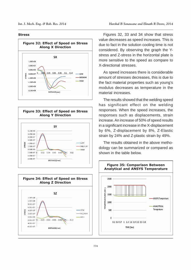
Figures 32, 33 and 34 show that stressvalue decreases as speed increases. This isdue to fact in the solution cooling time is notconsidered. By observing the graph the Y-stress and Z-stress in the horizontal plate ismore sensitive to the speed as compare toX-directional stresses.
As speed increases there is considerableamount of stresses decreases, this is due tothe fact material properties such as young’smodulus decreases as temperature in thematerial increases.
The results showed that the welding speedhas significant effect on the weldingresponses. When the speed increases, theresponses such as displacements, strainincrease. An increase of 50% of speed resultsin a significant increase in the X-displacementby 6%, Z-displacement by 8%, Z-Elasticstrain by 24% and Z-plastic strain by 49%.
The results obtained in the above metho-dology can be summarized or compared asshown in the table below.
Figure 35: Comparison BetweenAnalytical and ANSYS Temperature
Figure 32: Effect of Speed on StressAlong X Direction
Stress

775
Int. J. Mech. Eng. & Rob. Res. 2014 Harshal B Sonawane and Eknath R Deore, 2014
CONCLUSIONS FOR EFFECT
OF DIFFERENT PARAMETER
ON RESIDUAL STRESS
Complex welding phenomena can be simu-lated using a commercial Finite Elementpackage, viz., ANSYS. Special features ofbirth and death element has been used tosimulate the deposition of weld material.
1) Based on the simulation result, distor-tion or shrinkage of weldment can bepredicted. Thus the experimental analy-sis, which might be costly, can be avoi-ded.
2) Heat input and welding speed havesignificant effect on the weld response.The conclusion that can be drawn fromthe simulation result are as follows.
3) An increase of 12 % of heat input resultsin a significant increase in the Z-displacement (8%), and X-Elastic strain(60 %)and Z-Elastic strain (98 %).
4) When the speed increases, theresponses such as displacements,strain increase. An increase of 50% ofspeed results in a significant increasein the X-displacement by 6%, Z-displacement by 8%, Z-Elastic strain by24% and Z-plastic strain by 49%
FUTURE SCOPE
The current study only focuses on the soft-ware techniques to find out the temperatureof the plate thus, the future study can becarried out by setting up an experimentalmodel for calculating the temperature of thesame.
REFERENCES
1. Andrea Capriccioli and Paolo Frosi(2009), “Multipurpose ANSYS FEProcedure for Welding ProcessesSimulation”, ENEA CR Frascati, ViaEnrico Fermi 45, 00044 Frascati, Italy,Fusion Engineering and Design, Vol. 84,pp. 546-553.
2. Avinash Kharat and V V Kulkarni (2013),“Stress Concentration at Openings inPressure Vessels - A Review”. ResearchScholar, Dept. of Production Engineering,K. I. T.´s College of Engineering,Kolhapur, Maharashtra, India.International Journal of InnovativeResearch in Science, Engineering andTechnology, Vol. 2, No. 3.
3. B Brickstad, B L Josefsonb (1998), “AParametric Study of Residual Stresses inMulti-pass Butt-welded Stainless SteelPipes”. International Journal of PressureVessels and Piping, Vol. 75, pp. 1 l-25.
4. C Heinze, C Schwenk and M Rethmeier(2012), “Numerical Calculation ofResidual Stress Development of Multi-pass Gas Metal arc Welding Under HighRestraint Conditions”, a BAM FederalInstitute for Materials Research andTesting, Division 5.5 Safety of JoinedComponents, Unter den Eichen 87,12205 Berlin, Germany. Materials andDesign, Vol. 35, pp. 201-209.
5. D Devakumar, D B Jabaraj (2014),“Research on Gas Tungsten Arc Weldingof Stainless Steel - An Overview”,International Journal of Scientific &Engineering Research, Vol. 5, No. 1,1612 ISSN, pp. 2229-551.
776
Int. J. Mech. Eng. & Rob. Res. 2014 Harshal B Sonawane and Eknath R Deore, 2014
6. Dean Deng (2008), “Hidekazu Murakawa“Prediction of Welding Distortion andResidual Stress in a thin Plate Butt-welded Joint”, Joining and WeldingResearch Institute, Osaka University, 11-1, Mihogaoka, Ibaraki, Osaka 567-0047,Japan. Computational Materials Science,Vol. 43, pp. 353-365.
7. Ho-Sung Lee, Jong-Hoon Yoon and Jae-Sung Park (2005), “A Study on FailureCharacteristic of Spherical PressureVessel”, KSLV Technology Division,Korea Aerospace Research Institute, 45Eoeun-Dong, Yuseong-Gu, Daejeon,305-333, Republic of Korea.Journal ofMaterials Processing Technology, pp.164-165, 882-888.
8. L E Lindgren (2006), “NumericalModelling of Welding”, Comput. MethodsAppl. Mech. Engrg., Vol. 195, pp. 6710-6736.
9. M Abid and M Siddique (2005),“Numerical Simulation to Study the Effectof Tack Welds and Root Gapon WeldingDeformations and Residual Stresses ofa Pipe-flange Joint”, Graduate Student,
Faculty of Mechanical Engineering, GIKInstitute of Engineering Sciences andTechnology, Topi, NWFP, Pakistan.International Journal of Pressure Vesselsand Piping, Vol. 82, pp. 860-871.
10. Vishnu V S, Nadeera M and JoyVarghese V M (2014), “NumericalAnalysis of Effect of Process Parameterson Residual Stress in a Double Side TIGWelded Low Carbon Steel Plate”, Dept.of CIM, T.K.M College of Engg./KeralaUniversity, India. IOSR Journal ofMechanical and Civil Engineering (IOSR-JMCE) e-ISSN: pp. 2278-1684, p-ISSN:2320-334X pp. 65-68.
11. Wenge Zhang, Xuedong Chen, TiechengYang, Jianrong Li and Jilin Yu (2006),“Stress Analysis and Safety Assessmentfor Nozzle Welding Area Enduring HighPressure and High Temperature”,Department of Mechanics andMechanical Engineering, University ofScience and Technology of China, Hefei230027, Anhui, China.Journal ofPressure Equipment and Systems, Vol.4, pp. 86-90.