
Finite Element Analysis on Thermal Effect of the Vehicle ...
6
Proceedings of MUCEET2009 Malaysian Technical Universities Conference on Engineering and Technology June 20~22, 2009, MS Garden, Kuantan, Pahang, Malaysia MUCEET2009 Finite Element Analysis on Thermal Effect of the Vehicle Engine T.T.Mon, M.M.Noor, K.Kadirgama, Rosli A.Bakar, M.F.Ramli Abstract - Finite element method was employed to develop computational model to analyze the temperature distribution in the vehicle engine that utilized spark-ignition system for power generation. Computational domain consists of combustion chamber as major part and its surrounding components such as valves, and exhaust port and water jacket. Simplified 2-dimensional model was developed using general-purpose FE code. The element type was 2D element. Material properties were taken from FE package library. Heat convection due to the presence of water was defined by convection coefficient. Thermal load due to combustion was defined to all nodes of combustion chamber. The finite element models were analyzed using the thermal transient heat transfer analysis. The computed results were validated by comparing the maximum temperature at the piston surface with the published result. The results were found to be agreeable. The computed temperature gradient at the crucial parts were plotted and discussed. It was found that the critical component in thermal fatigue was the exhaust port near the cylinder head and the material used to construct the engine part strongly influences the temperature distribution in the engine. Keywords: Finite element method, thermal analysis, vehicle engine Introduction Vehicle or automobile engines are major parts that contribute to means of transportation. Researchers in T.T.Mon, M.M.Noor and M.F.Ramli are from the Faculty of Mechanical Engineering, Universiti Malaysia Pahang, 26300 UMP, Kuantan, Pahang, Malaysia, Email: [email protected] / [email protected] K.Kadirgama and Rosli Abu Bakar are from the Automotive Excellent Center, Universiti Malaysia Pahang, Phone: +609- 5492233 Fax: +609-5492244. Email: [email protected] automotive field have emphasized on improvement of engine design since long fuel economy and environmental impact from transportation become a global concern. Research focus, to name a few, includes introducing new engine material, bio-fuel cell, spark-free operating, hybrid engine and electric engine. Methodology in these researches relies on large amount of experimentations. Nevertheless, vehicle engines are considered not-well-improved yet from the view point of fuel economy and environmental impact. One reason of high fuel consumption and pollution is that quarter of energy is wasted as heat. It is beneficial if possible to reuse this heat lost to gain more power and also to reduce amount of fuel consumption. One way to help out this, knowledge of temperature distribution in the engine is important to be known [NASA, 2004]. Recently, few researchers have turned their attention to applying computer-aided engineering (CAE) tools to improve engine design as experimental works are costly and time consuming. Among the CAE tools, finite element method (FEM) has been widely used to develop computational models in a variety of field due to being benchmarked and its advantages. Some of the advantages are: complex geometries can be analyzed incorporating a variety of deformation models and complex boundary conditions. Some major finite element codes to date are ABAQUS, ANSYS and ALGOR [Gosz, 2006; Edward, 2007]. The objective of this work is to develop a computational model of a spark-ignition engine using finite element method. This novel model would be useful to find out useful information such as the temperature distribution in an internal combustion engine, localized temperature in the engine, and critical part of the engine where thermal damage may occur. Figure 1 illustrates major part of typical engine in which a park ignition (SI) system is utilized for combustion process. Combustion occurs when the compressed mixture of air and fuel inside the cylinder is ignited by a heat source from a spark plug. The combustion temperature may be as high as 2000C in one cycle. Such a high and repeated thermal operation very often causes the fatigue failure of the engine component [John, 1988].
Transcript of Finite Element Analysis on Thermal Effect of the Vehicle ...

Proceedings of MUCEET2009
Malaysian Technical Universities Conference on Engineering and Technology June 20~22, 2009, MS Garden, Kuantan, Pahang, Malaysia
MUCEET2009
Finite Element Analysis on Thermal Effect of the Vehicle Engine
T.T.Mon, M.M.Noor, K.Kadirgama, Rosli A.Bakar, M.F.Ramli
Abstract - Finite element method was employed to develop computational model to analyze the temperature distribution in the vehicle engine that utilized spark-ignition system for power generation. Computational domain consists of combustion chamber as major part and its surrounding components such as valves, and exhaust port and water jacket. Simplified 2-dimensional model was developed using general-purpose FE code. The element type was 2D element. Material properties were taken from FE package library. Heat convection due to the presence of water was defined by convection coefficient. Thermal load due to combustion was defined to all nodes of combustion chamber. The finite element models were analyzed using the thermal transient heat transfer analysis. The computed results were validated by comparing the maximum temperature at the piston surface with the published result. The results were found to be agreeable. The computed temperature gradient at the crucial parts were plotted and discussed. It was found that the critical component in thermal fatigue was the exhaust port near the cylinder head and the material used to construct the engine part strongly influences the temperature distribution in the engine. Keywords: Finite element method, thermal analysis, vehicle engine
Introduction Vehicle or automobile engines are major parts that contribute to means of transportation. Researchers in T.T.Mon, M.M.Noor and M.F.Ramli are from the Faculty of Mechanical Engineering, Universiti Malaysia Pahang, 26300 UMP, Kuantan, Pahang, Malaysia, Email: [email protected] / [email protected] K.Kadirgama and Rosli Abu Bakar are from the Automotive Excellent Center, Universiti Malaysia Pahang, Phone: +609-5492233 Fax: +609-5492244. Email: [email protected]
automotive field have emphasized on improvement of engine design since long fuel economy and environmental impact from transportation become a global concern. Research focus, to name a few, includes introducing new engine material, bio-fuel cell, spark-free operating, hybrid engine and electric engine. Methodology in these researches relies on large amount of experimentations. Nevertheless, vehicle engines are considered not-well-improved yet from the view point of fuel economy and environmental impact. One reason of high fuel consumption and pollution is that quarter of energy is wasted as heat. It is beneficial if possible to reuse this heat lost to gain more power and also to reduce amount of fuel consumption. One way to help out this, knowledge of temperature distribution in the engine is important to be known [NASA, 2004]. Recently, few researchers have turned their attention to applying computer-aided engineering (CAE) tools to improve engine design as experimental works are costly and time consuming. Among the CAE tools, finite element method (FEM) has been widely used to develop computational models in a variety of field due to being benchmarked and its advantages. Some of the advantages are: complex geometries can be analyzed incorporating a variety of deformation models and complex boundary conditions. Some major finite element codes to date are ABAQUS, ANSYS and ALGOR [Gosz, 2006; Edward, 2007]. The objective of this work is to develop a computational model of a spark-ignition engine using finite element method. This novel model would be useful to find out useful information such as the temperature distribution in an internal combustion engine, localized temperature in the engine, and critical part of the engine where thermal damage may occur.
Figure 1 illustrates major part of typical engine in which a park ignition (SI) system is utilized for combustion process. Combustion occurs when the compressed mixture of air and fuel inside the cylinder is ignited by a heat source from a spark plug. The combustion temperature may be as high as 2000C in one cycle. Such a high and repeated thermal operation very often causes the fatigue failure of the engine component [John, 1988].

Proceedings of MUCEET2009
Malaysian Technical Universities Conference on Engineering and Technology June 20~22, 2009, MS Garden, Kuantan, Pahang, Malaysia
MUCEET2009
Figure 1. Schematic of spark-ignition system in vehicle engine [John, 1988].
In the past, many researchers had done the research on thermal analysis of vehicle engine using different approaches the core objective of improving the engine performance. The analysis was concentrated on specific parts of the engine. Li (1982) developed a quarter model of the piston based on finite element method to analyze its thermal behavior. Symmetric thermal boundary conditions and simple combustion model for combustion side boundary condition were defined to the piston. The numerical results were well-matched with experiment. On the other hand, different combustion boundary conditions were treated differently in (Esfahanian, 2005) when carrying out the piston thermal analysis. In order to do so, a good interface between NASTRAN and KIVA-3V codes was developed. It was found that using spatial and time averaged combustion boundary condition is an effective way compared to surface and time averaged boundary condition. The behaviors of heat conduction between the engine body and other components were also extensively investigated by FEM. Chyuan (2000) proposed finite element model of a cylinder structure with a twin-cam 16-valve. They used the MSC/NASTRAN FE code to predict the thermal and stress/strain results at various loading conditions and operating environments. The structural analyses of a cylinder head were performed in (Chang, 2004) under various loading conditions accomplished by numerical simulation using finite element analysis. It was reported that the capacity of gasket sealing mainly depends upon the pre-stressing of the bolts, which was the source of the maximum external loading on the inner structure of the cylinder head. In addition, the location of the weakest contact pressure on the raised portion of the gasket can be transferred as a result of the effect of thermal stress/strain. Important information was also found in (Serth, 2007) which stated that the highest temperature of any point in each component must not exceed more
than 66% of the melting point temperature of the material. Methodology Engine model is simplified into 2-D model focusing on combustion chamber. Subsequently, computational domain was made up of combustion chamber as major part, valves, and some portion of exhaust port and piston. The dimensions and materials of all parts was the same that of the actual vehicle model. The materials properties were available in the FE package used (ALGOR, 2008). The models were discretized with 2D element in automatic generator using the element size as small as 0.001. The element type used was 2D element. All parts were discretized except the water jacket. Despite simplification of the model, model discretization took times to complete due to the presence of irregular geometries, many different parts of high aspect ratio. Feasible element size of 0.001 was chosen through trial-meshing. Total numbers of elements were 24921. Figure 2 illustrates a complete FE model. Currently, isotropic material properties were assumed. The initial temperature for each part in the engine was assigned as 27C. The presence of water coolant was modeled by assigning convection coefficient of water on all surfaces of water jacket (Yong and Reitz, 1998). In order to represent the combustion occurrence, nodal temperature in the combustion chamber was defined to be 2100C (Charles, 2002). The analysis time was set to be 0.12 s being consistent with the actual combustion period. Transient heat transfer analysis was performed. In this analysis, the specific heat (Cp) and density (ρ) are major parameters. The rate of energy decrease in an element is (ρ) (Cp) (dT/dt) where dT/dt is the rate of change in temperature. Details can be found in (ALGOR, 2008; Gosz, 2006; Serth, 2007).
Exhaust valve
Air-fuel mixture
Piston

Proceedings of MUCEET2009
Malaysian Technical Universities Conference on Engineering and Technology June 20~22, 2009, MS Garden, Kuantan, Pahang, Malaysia
MUCEET2009
Figure 2. Finite element model of SI Engine.
Results and Discussion Figure 3 depicts the computed overall temperature across the combustion chamber and its surrounding components. The computed result
validated by comparing with the published result (Esfahanian, 2005). The computed maximum temperature at the piston surface was about 220C while in the published data was 223C. The percentage of error is only 1.37%. Therefore the computed results are acceptable.
Figure 3. Overall temperature distribution
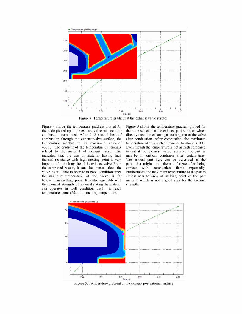
Figure 4. Temperature gradient at the exhaust valve surface.
Figure 4 shows the temperature gradient plotted for the node picked up at the exhaust valve surface after combustion completed. After 0.12 second heat of combustion through the exhaust valve surface, the temperature reaches to its maximum value of 430C. The gradient of the temperature is strongly related to the material of exhaust valve. This indicated that the use of material having high thermal resistance with high melting point is very important for the long life of the exhaust valve. From the computed results, it can be stated that the valve is still able to operate in good condition since the maximum temperature of the valve is far below than melting point. It is also agreeable with the thermal strength of material stating the material can operates in well condition until it reach temperature about 66% of its melting temperature.
Figure 5 shows the temperature gradient plotted for the node selected at the exhaust port surfaces which directly meet the exhaust gas coming out of the valve after combustion. After combustion, the maximum temperature at this surface reaches to about 310 C. Even though the temperature is not as high compared to that at the exhaust valve surface, the part is may be in critical condition after certain time. The critical part here can be described as the part that might be thermal fatigue after being contact with combustion flame repeatedly. Furthermore, the maximum temperature of the part is almost near to 66% of melting point of the part material which is not a good sign for the thermal strength.
Figure 5. Temperature gradient at the exhaust port internal surface

Figure 6 shows the temperature gradient for the node chosen at the cylinder wall after combustion. The maximum temperature was found as 195C. The result showed that the lowest maximum temperature occurred at the cylinder wall compared to other surrounding components that contact with combustion flame. The prominent effect of cooling
was also evident. The result also indicated the appropriateness of material used to construct cylinder wall as the gas-side surface of the cylinder wall must be kept below 200C to prevent deterioration of the lubricating oil film. The deterioration of oil film problem may affect engine performance and efficiency.
Figure 6. Temperature gradient at the cylinder wall Conclusion Finite element model of a vehicle engine has been successfully developed and simulated to analyze heat transfer during combustion process. The computational analysis had been carried out in order to obtain temperature distribution across the engine. The results of finite element analysis have been found to be in good agreement with the published report. The finite element prediction has indicated that thermal effect in the combustion chamber is influenced by major parameters such as combustion flame temperature, convection of cooling system, and thermal properties of engine component materials. It was found that the choice of material for part component in the combustion chamber is one of the solutions in order to improve engine performance and efficiency. Besides, the geometry and dimension of the engine parts also can be considered in order to improve the engine performance.
Acknowledgment The authors would like to thanks the Universiti Malaysia Pahang for providing financial support.
References ALGOR V22 Modelling, (2008). ASM Handbook, (1990), Properties and Selection: Irons, Steels and High Performance Alloy, ASM International vol 1. Chang C.L. (2004). Design and analysis of gasket sealing of cylinder head under engine operation conditions. Charles L.G. (2002). Controlled Temperature Combustion Engine. Chyuan S.W. (2000). Finite element simulation of a twin-cam 16-valve cylinder structure, Finite Element Analysis. Edward L. W. (2007). Early Finite Element Research at Berkeley.

Esfahanian, V.(2005). Thermal analysis of an SI engine piston using different combustion boundary condition treatments. Gosz, M.R. (2006). Finite Element Method: Applications in Solids, Structures and Heat Transfer, CRC Taylor & Francis. John B. H. (1988). Internal Combustion Engine Fundamentals. Li C.H. (1982). Piston thermal deformation and friction considerations, SAE Paper 820086. NASA technical briefs, 2004. Serth R.W.(2007). Process of Heat Transfer, Principle and Application. Yong L., Reitz R.D. (1998). Modeling of heat conduction within chamber walls for multidimensional internal combustion engine simulation, Int. J. Heat and Mass Transfer 41, 859– 869.