Infancy and Childhood Development Alla Greben Maria Anakotta Eric Huenefeld.

FINITE ELEMENT ANALYSIS OF SUPERPLASTIC FORMING PROCESS, USING FLUENT (ANSYS)
GREBENIŞAN Gavril1, ROMOCEA Sanda2
1-University of Oradea, 2-Drumuri Judeţene Bihor [email protected]
Keywords: Finite Element Analysis, superplastic forming, numerical methods, FLUENT Abstract: Settings of the ANSYS software, into FLUENT Analysis System, starting with modelling of analysis work, are presented in this paper. Using geometry and mesh models, [10], one present relevantly steps of a simple analysis of superplastic forming, using, as work agent, the air pressure. This is the reason because the FLUENT Analysis System were chosen. The workpiece (an aluminum alloy, FORMALL 100), were deformed, at 560 Celsius degrees, with 0,005 s-1 strain rate. Experimental data was compared with theoretical data, the results obtained have confirmed hundred percents, material’s behaviour. 1. INTRODUCTION The workpiece having 1.2.mm initial width, were deformed untill to reaching, aproximately, 7.5 mm in depth, the hemispherical chord, because the aim of this forming stage was the study of superplastic behaviour, by measuring the width variation on various stages of forming process, in order to issue conclusions referring on forming tendencies and on the influence of temeprature maintaining on thinning degree of gasostatic formed pieces. This workpiece were sectioned and measured on 20 different points also an workpiece completely deformed, at 17.5 mm in depth, also were sectioned and measured on 20 diferrent points. In oredr to obtain a deformed curve profile, were measured that 20 points, on symetrical points situated on cross section of the workpiece. 2. ANALYSIS OF BEHAVIOUR MODEL Analysis model consists on following steps: type of phases, opportunity of energy calculus, type of flow, defined such as showed on next captures:
a) b)
Figure 1-Type of analysis, a), and energy calculus enabled, b)
In order to set up the turbulence and/or laminar type of fluid flow dynamic, one should choose this from a set of options available on FLUENT Analysis System. For this case one have chosen a “laminar” flow of air, as work agent, and the governing equation is stated as two k-epsilon type. The k-epsilon Model may be chosen from three options (Standard, RNG and Realizable), most appropriate one is Realizable, for this case. Fluid flow, into the nearest of the wall of die, will be treted as default parameters (implicit), also Prandtl Numbers:
ANNALS of the ORADEA UNIVERSITY. Fascicle of Management and Technological Engineering, Volume IX (XIX), 2010, NR3
1.70

a) b)
Figure 2 – Laminar flow settings, a), and type of governing equation, b) 3. DEFINING MATERIALS There should be defined two types of materials: fluid (air, as work agent), and aluminum, for workpiece material. The die will be considered such as environment enclosure, which not interact with other materials, and no influences towards fluid and workpiece materials properties. Setting up materials consists on third chapter of Problem Setup, namely third analysis section. This is one of most important section of the analysis, because here one define the behaviour of the next manufactured article.
a) b)
Figure 3 – Defining materials, a)-fluid, b)-air properties
The properties of fluid, named “air”, will be chosen from ANSYS (FLUENT) materials database. These properties have to be copied from ANSYS (FLUENT) datanase into workspace settings. If user materials needs to be defined, the database materials, for default general database of materials properties, there one should define this such “user defined material”, but in this case, “air” is commonly gas, work agent defined. No necessary, more properties to be defined.
ANNALS of the ORADEA UNIVERSITY. Fascicle of Management and Technological Engineering, Volume IX (XIX), 2010, NR3
1.71
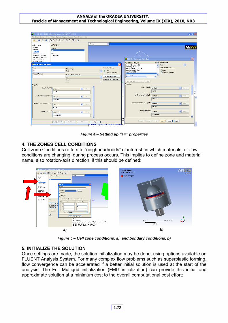
Figure 4 – Setting up “air” properties 4. THE ZONES CELL CONDITIONS Cell zone Conditions reffers to “neighbourhoods” of interest, in which materials, or flow conditions are changing, during process occurs. This implies to define zone and material name, also rotation-axis direction, if this should be defined:
a) b)
Figure 5 – Cell zone conditions, a), and bondary conditions, b)
5. INITIALIZE THE SOLUTION Once settings are made, the solution initialization may be done, using options available on FLUENT Analysis System. For many complex flow problems such as superplastic forming, flow convergence can be accelerated if a better initial solution is used at the start of the analysis. The Full Multigrid initialization (FMG initialization) can provide this initial and approximate solution at a minimum cost to the overall computational cost effort:
ANNALS of the ORADEA UNIVERSITY. Fascicle of Management and Technological Engineering, Volume IX (XIX), 2010, NR3
1.72

Figure 6 – Flow convergence (using FMG)
The FMG it’s a procedure for initialization and may be accessed on using the text user interface (TUI) once the standard flow initialization is performed. The result of FMG procedure offered by ANSYS FLUENT consists first of all on output the multigrid level information followed by convergence history for the Full-Approximation Storage (FAS) multigrid cycle on each level. The normalized residual value is printed after ten FAS cycles or when the number of FAS cycles is reached. The output will indicate when convergence is reached on each level and when the solution is being interpolated to the next level, [15]:
Figure 7 - Full-Approximation Storage multigrid cycle reached
6. MONITORS SETTINGS In order to vizualize, online during the process occurs, or final results, one should be setting the “Monitors”:
ANNALS of the ORADEA UNIVERSITY. Fascicle of Management and Technological Engineering, Volume IX (XIX), 2010, NR3
1.73

Figure 8 –Setting up the monitors One or more monitors may be setup. Default monitors are available on ANSYS FLUENT system for “Residuals”, “Statistics”, “Moments” and others. This monitors will provide, opportunity for reach the results and materials behaviour, on process occurs. 7. RUN CALCULATION Most time calculation effort, comparable with meshing process, consists on finding solution, namely run calculation. Depends on accuracy and complexity of process analized, calculation of the solution spends time and computation effort:
Figure 9 – Run calculation, solution complete
8. RESULTS-ANALYSIS OF PARAMETERS Runing calculation and got the complete solution consists on more spectacular section of each Finite Element Analysis. As you can see, into following figures, every parameters which users set on “Monitors” section of this analysis may be analized, shown and captured:
ANNALS of the ORADEA UNIVERSITY. Fascicle of Management and Technological Engineering, Volume IX (XIX), 2010, NR3
1.74
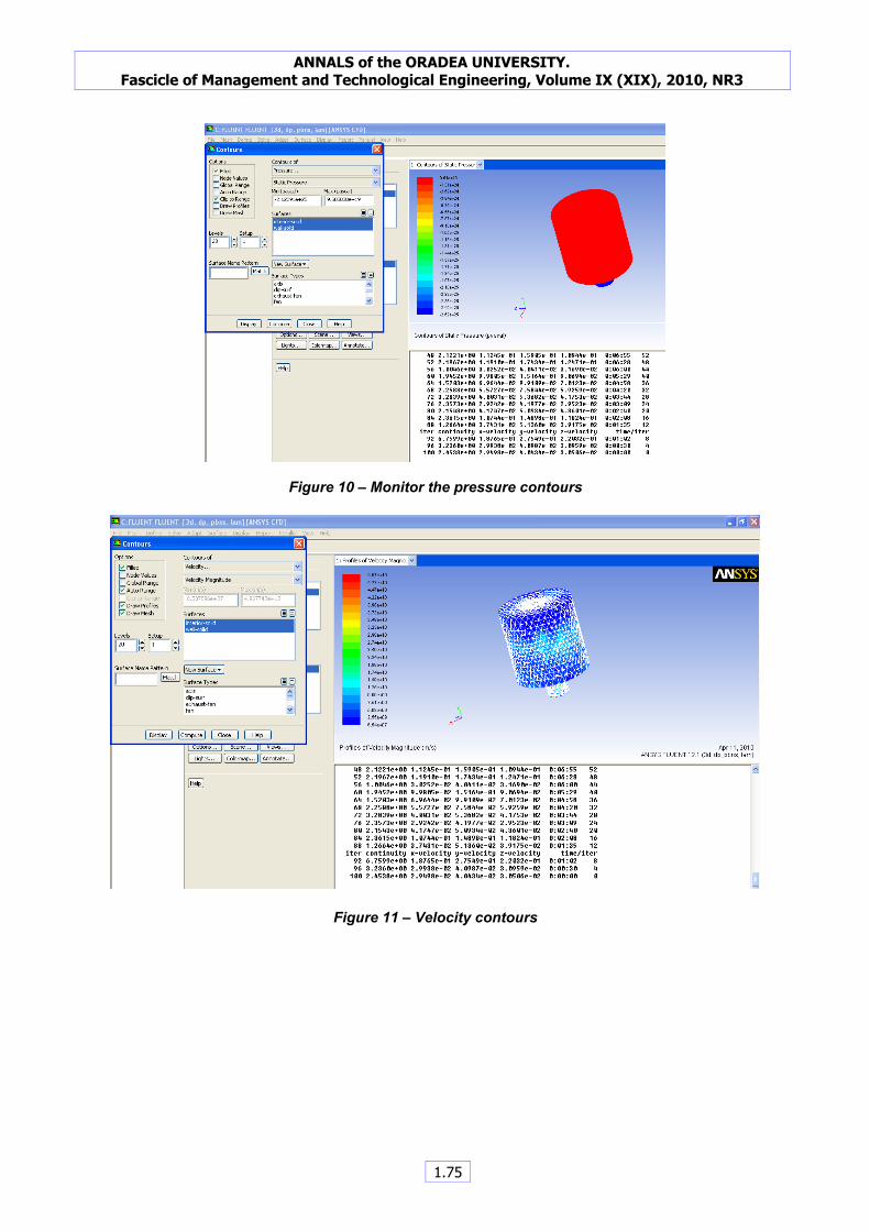
Figure 10 – Monitor the pressure contours
Figure 11 – Velocity contours
ANNALS of the ORADEA UNIVERSITY. Fascicle of Management and Technological Engineering, Volume IX (XIX), 2010, NR3
1.75

Figure 12 – Residuals plot
Figure 13 – Temperature contours 9. CONCLUSIONS The workpiece manufactured by superplastic forming (fig. 14) has cross sectioned to find more accurately the thin wall variation:
a) b)
Fig. 14: a)-deformed worpiece profile, b)-axial cross section, (zoom)
ANNALS of the ORADEA UNIVERSITY. Fascicle of Management and Technological Engineering, Volume IX (XIX), 2010, NR3
1.76

Performing Finite Element Analysis at this stage of deformed part, (shown on fig. 14), one may study deformation strain state and distribution of stress (von Mises equivalent stress). Using ANSYS- Static Structural facilities, it may view the uniformity of this distribution:
a) b)
Figure 15 – Von Mises equivalent stress, a)-start, b)-finish
The quality of analysis settings resides on quality of data obtained after simulation and process parameters. The “safety factor” shows the accuracy of simulation and confirms convergence of the paramaters, fig. 16. Red zone shows that the most exposed surface is free surfaces of the workpiece, and contact zone (yelow and green) exhibit a restricted area:
Figure 16 –Safety factor
The profile of deformed workpiece presented on next figure (fig. 17) captured on the final of the process show the behaviour of the material, and are attached to the tetrahedron mesh structure (spatial distribution). These images do not presents the real profile of the
ANNALS of the ORADEA UNIVERSITY. Fascicle of Management and Technological Engineering, Volume IX (XIX), 2010, NR3
1.77

deformed workpiece, there are prezented the finite elements “charged” and “deformed” at that stage:
Figure 17 – Total deformation Finite Eelement Analysis using FLUENT ANSYS offers many opportunities to study and analyse process with behaviour complexity of materials and parameters. References [1] KONRAD, A.-"Integrodifferential Finite Element Formulation of Two-Dimensional Steady-State Skin Effect Problems", IEEE Trans. Magnetics, Vol. MAG-18 No. 1, January 1982, pg. 284-292. [2] AHMED, H. & PEARCE, R.- “Superplasticity in Aerospace – Alumium”, Ed. R. Pearce&L. Kelly, publ. Cranfield Institute of Technology, Bedford, 1986, pag. 146-159. [3] ARGYRIS, J., DOLTSINIS, J. S. - An Aperçu of Superplastic Forming, in " Plasticity today. Modelling, Methods and Applications " , ed. A.Sawczuk, Elsevier Applied Science Publishers, London, 1993. [4] ARGYRIS, J., DOLTSINIS, J. S. - A Primer on Superplasticity in Natural Formulation, "Computer Methods in Applied Mechanics and engineering ", vol.46, pag.83-131, 1992 [5] BEER, G.,ş.a.- Introduction to finite and boundary element methods for engineering, John Wiley & Sons, 1975. [6] BEJU, I.,ş.a. - Tehnici de calcul tensorial euclidian cu aplicaţii, Editura Tehnică, Bucureşti, 1977. [7] BONET, J. - Numerical Simulation of the Superplastic Forming of Thin Sheet Components Using the Finite Element method, " International Journal for Numerical Methods in Engineering", vol. 30, pag. 1719- 1737, 1990. [8] CHANDRA, N.- Membrane element analyssis of axisymetric and non- axisymetric superplastic metal forming processes, "Superplasticity and Superplastic Forming", ed. C.H. Hamilton & N. E. Paton, Warendale, 1989 . [9] GÂRBEA, D - Analiză cu elemente finite, Editura Tehnică, Bucureşti,1990 . [10] GREBENIŞAN, G. - Finite element analysis of superplastic forming process, using ANSYS, Annals of University of Oradea, Fascicle of Management and Technological Engineering, 2010. [11] JOVANE, F. – An aproximate analysis of the superplastic forming of thin circular diaphragm: theory and experiment, International Journal of mechanical Science, vol. 6, 1968, pag. 403-428. [12] KOBAYASHI, S. - Metal Forming and the Finite Element Method, Oxford Universitz Press, New York, 1989. [13] MOAVENI, S. – Finite Element Analysis, Theory and Application with ANSYS, Prentice Hall, New Jersey, 1999. [14] www.ansys.com [15] Theory Reference for the Mechanical APDL and Mechanical Applications (ANSYS)
ANNALS of the ORADEA UNIVERSITY. Fascicle of Management and Technological Engineering, Volume IX (XIX), 2010, NR3
1.78