Finite Element Analysis of Glass Vacuum Windows of the ...
17
Acta Technica Jaurinensis Vol. 8, No. 4, pp. 330-346, 2015 DOI: 10.14513/actatechjaur.v8.n4.390 Available online at acta.sze.hu 330 Finite Element Analysis of Glass Vacuum Windows of the “COMPASS” Tokamak in Prague Z. Molnár 1 , J. Égert 1 , M. Berta 2,3 1 Széchenyi István University, Department of Applied Mechanics Egyetem tér 1., 9026 Győr, Hungary E-mail: [email protected] 2 Széchenyi István University, Department of Physics and Chemistry Egyetem tér 1., 9026 Győr, Hungary 3 Institute of Plasma Physics AS CR, v.v.i., Tokamak Department Za Slovankou 1782/3, 182 00 Prague, Czech Republic Abstract: In this paper is described the mechanical stress analysis of glass vacuum windows of the "COMPASS" tokamak using Finite Element Method. As a reference test problem the problem of uniformly loaded glass vacuum win- dow with circular shape has been chosen, which problem can be solved also analytically. In the case of Finite Element analysis we used two different mechanical models: 3-dimensional (3D) approach and shell modelling. For 3D approach an optimal finite element type - quadratic tetrahedron element with appropriate size - was chosen, and for shell modelling a thin axisym- metric shell element type - shell 209 - was applied. The analytic and both numerical results have been compared and summarized. Keywords: stress analysis, Finite Element Method (FEM), glass vacuum windows, the “COMPASS” tokamak, shell element, deformation, equivalent (von Mises) stress 1. Introduction The purpose of analysis presented in this paper is to verify mechanical resistance of vacuum windows on the "COMPASS" tokamak through numerical stress analysis. This analysis has been carried out using Finite Element (FE) modelling. As the FE modelling tool we used the programme package ANSYS. The main structure of this paper is the following: after the general introduction (Chapter 1.) we introduce the “COMPASS” tokamak in Prague and the geometrical model of its vacuum windows as objects of our tests (Chapters 2.,3.);
Transcript of Finite Element Analysis of Glass Vacuum Windows of the ...

Acta Technica Jaurinensis
Vol. 8, No. 4, pp. 330-346, 2015DOI: 10.14513/actatechjaur.v8.n4.390
Available online at acta.sze.hu
330
Finite Element Analysis of Glass Vacuum Windows of the “COMPASS” Tokamak in Prague
Z. Molnár1, J. Égert1, M. Berta2,3
1Széchenyi István University, Department of Applied Mechanics Egyetem tér 1., 9026 Győr, Hungary
E-mail: [email protected]
2Széchenyi István University, Department of Physics and Chemistry Egyetem tér 1., 9026 Győr, Hungary
3Institute of Plasma Physics AS CR, v.v.i., Tokamak Department Za Slovankou 1782/3, 182 00 Prague, Czech Republic
Abstract: In this paper is described the mechanical stress analysis of glass vacuum windows of the "COMPASS" tokamak using Finite Element Method. As a reference test problem the problem of uniformly loaded glass vacuum win-dow with circular shape has been chosen, which problem can be solved also analytically. In the case of Finite Element analysis we used two different mechanical models: 3-dimensional (3D) approach and shell modelling. For 3D approach an optimal finite element type - quadratic tetrahedron element with appropriate size - was chosen, and for shell modelling a thin axisym-metric shell element type - shell 209 - was applied. The analytic and both numerical results have been compared and summarized.
Keywords: stress analysis, Finite Element Method (FEM), glass vacuum windows, the “COMPASS” tokamak, shell element, deformation, equivalent (von Mises) stress
1. Introduction
The purpose of analysis presented in this paper is to verify mechanical resistance of vacuum windows on the "COMPASS" tokamak through numerical stress analysis. This analysis has been carried out using Finite Element (FE) modelling. As the FE modelling tool we used the programme package ANSYS.
The main structure of this paper is the following:
after the general introduction (Chapter 1.) we introduce the “COMPASS” tokamak in Prague and the geometrical model of its vacuum windows as objects of our tests (Chapters 2.,3.);

Z. Molnár et al. – Acta Technica Jaurinensis, Vol. 8, No. 4, pp. 330-346, 2015
331
as a reference problem we remind the analytical solution for displacement and stress in the case of window with circle shape fixed along its perimeter and with uniformly distributed pressure as the load (Chapter 4.);
in Chapter 5. we solve the problem for different shapes numerically (as a 3D model and also as a shell model);
and finally, Chapter 6. consists of the summary of results and conclusions.
2. The "COMPASS" tokamak and its glass vacuum windows
The "COMPASS" tokamak of IPP-CR in Prague is a medium size fusion device producing plasma with ITER-like shape [1]. Proper operation of such fusion devices need to fulfil some necessary prerequisites (Fig. 1.):
enough energy to produce and maintain high magnetic fields and huge electric cur-rents;
very high vacuum in the reaction chamber;
and very clean first wall.
Requirement of the vacuum inside the tokamak chamber during operation is very strict. Pressure inside the vessel must be below of 85 10 Pa during regular operation. The ful-filment of this requirement needs powerful vacuum pumps and to seal all ports on the vacuum system properly.
Some ports were designed as diagnostic ports for optical observation of plasma inside the chamber. These ports are equipped with high quality 2SIO glass vacuum windows.
The glass vacuum windows on diagnostic ports for optical observation were welded using electron beam welding technology which allows welding of steel to glass [2, 3] and results are high quality vacuum windows with extremely good vacuum sealing. Even the smallest displacement of the glass in this type of windows is excluded because of the required high vacuum in the reaction chamber.
Figure 1. View of the "COMPASS" tokamak (left) and its vacuum chamber with diag-nostic ports (right)

Z. Molnár et al. – Acta Technica Jaurinensis, Vol. 8, No. 4, pp. 330-346, 2015
332
3. Mechanical model
The vacuum chamber of the "COMPASS" tokamak (Fig. 2.) is equipped with two types of vacuum windows of different shapes, circular and oval (Fig. 3.).
Figure 2. Locations of vacuum windows on the "COMPASS" tokamak
The geometric model of both types of vacuum windows is shown in Fig. 3.
Figure 3. Shapes (circular and oval) of vacuum windows of the "COMPASS" tokamak
The thickness of glass in vacuum windows is h = 8.5 mm. Windows were made from normal 2SIO glass with the following mechanical properties: Young's modulus is E =
72 GPa, Poisson’s ratio is ν = 0.23 and tensile strength is mR = 50 MPa (which
strongly depends on the state of surface [2, 4]). The other (geometric) parameters (R, L) of these windows are collected in Tab. 5.
The pressure outside the device is the normal atmospheric pressure (~ 510 Pa) and
inside of it is in the range of 85 10 0 : Pa (~ vacuum). The difference of these two
pressures is the load on the outer surface of vacuum windows 510 Pap . All windows
are fixed along their perimeters. The optimal 3D and shell meshing for FE analysis has been chosen (see Chapter 5.) on the base of existing analytical solution for the window with circular shape.
4. Reference problem with analytical solution
Firstly, we remind the analytical solution for displacement and stress in the case of circular window as a reference problem [5, 6, 7].
Z. Molnár et al. – Acta Technica Jaurinensis, Vol. 8, No. 4, pp. 330-346, 2015
333
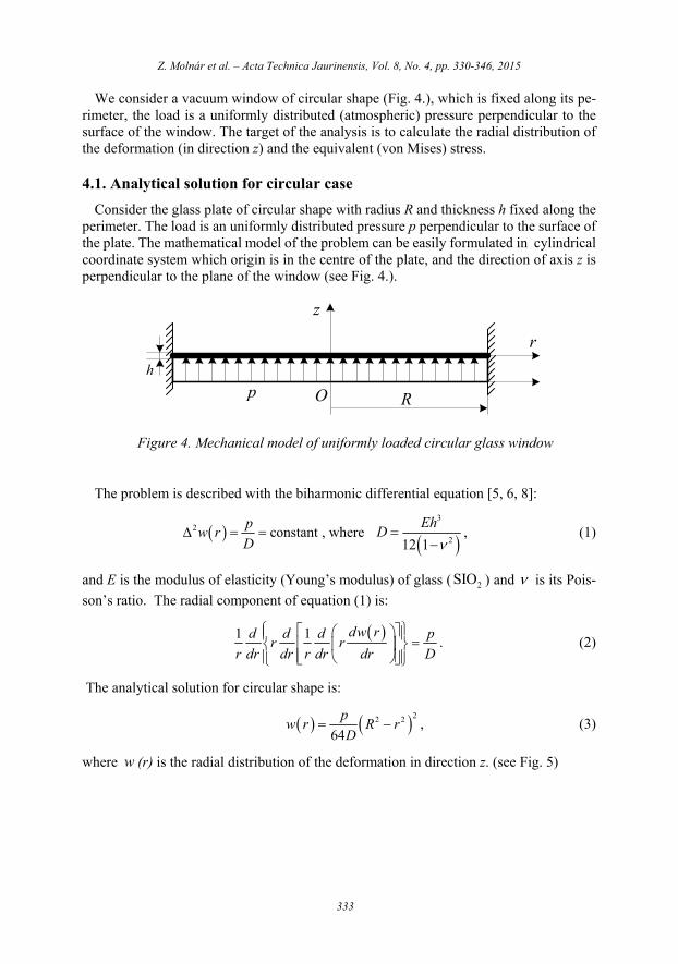
We consider a vacuum window of circular shape (Fig. 4.), which is fixed along its pe-rimeter, the load is a uniformly distributed (atmospheric) pressure perpendicular to the surface of the window. The target of the analysis is to calculate the radial distribution of the deformation (in direction z) and the equivalent (von Mises) stress.
4.1. Analytical solution for circular case
Consider the glass plate of circular shape with radius R and thickness h fixed along the perimeter. The load is an uniformly distributed pressure p perpendicular to the surface of the plate. The mathematical model of the problem can be easily formulated in cylindrical coordinate system which origin is in the centre of the plate, and the direction of axis z is perpendicular to the plane of the window (see Fig. 4.).
r
z
Rp O
h
Figure 4. Mechanical model of uniformly loaded circular glass window
The problem is described with the biharmonic differential equation [5, 6, 8]:
2 constantp
w rD
, where
3
212 1
EhD
, (1)
and E is the modulus of elasticity (Young’s modulus) of glass ( 2SIO ) and is its Pois-
son’s ratio. The radial component of equation (1) is:
1 1 dw rd d d pr r
r dr dr r dr dr D
. (2)
The analytical solution for circular shape is:
22 2
64
pw r R r
D , (3)
where w (r) is the radial distribution of the deformation in direction z. (see Fig. 5)

Z. Molnár et al. – Acta Technica Jaurinensis, Vol. 8, No. 4, pp. 330-346, 2015
334
Figure 5. Analytical solution of displacement w(r) in direction z for circular window under homogeneous pressure load (R=75 mm, h=1 mm, p=105 Pa)
The calculated displacement from the formula (3) at the centre of the window is
max 7.8040 mmw in the test case (R=75 mm, h=1 mm). The maximal displacement is
max 0.0215 mmw in the real case (R=85.575 mm, h=8.5 mm).
4.2. Analytical solution for stresses
Radial and tangential torques ,r tM M can be calculated from following expressions
(see [8]): 2
2
1 1( ) ,t
r t
dd w dwM r D D
r dr dr rdr
(4)
2
2
1 1( ) t
t t
dd w dwM r D D
r dr dr rdr
, (5)
where t is the rotation angle around t axis.
From formulas (4) and (5) maximum values of torques and stresses at 2
hz can be
calculated:
2 2( ) 1 3 ,16r
pM r R r v max 2
( )( ) 6 r
r
M rr
h , (6)
2 2( ) 1 1 316t
pM r R r , max 2
( )( ) 6 t
t
M rr
h . (7)
In Fig. 6. the distributions of torques ( )rM r , ( )tM r are shown:

Z. Molnár et al. – Acta Technica Jaurinensis, Vol. 8, No. 4, pp. 330-346, 2015
335
Figure 6. Distribution of radial and tangential torques ( )rM r , ( )tM r in the case of
circular window with testing parameters R=75 mm, h=1mm
At the perimeter of the window r R one can get:
2
08r r R
pRM
,
2
08t r R
pRM
, r tr R r R
M M
, (8)
and in the centre of the window 0r :
2
0 01 0.
16r tr r
pRM M
(9)
The maximum value of torque in both cases is along the fixed perimeter of the window, therefore there is the critical location.
The equivalent stress von Miseseq is defined by the formula (10):
2 2 2 2 2 216
2eq x y y z x z xy yz xzvon Mises , (10)
where i are normal stresses and i j are shear stresses from the stress tensor F :
x xy xz
yx y yz
xyzzx zy z
F
. (11)
The stress tensor can be transformed into the coordinate system defined by its eigenvec-tors (so called main axes coordinate system), and in this system the stress tensor is diag-onal:

Z. Molnár et al. – Acta Technica Jaurinensis, Vol. 8, No. 4, pp. 330-346, 2015
336
1 2 3
1
2
3
0 0
0 0
0 0e e e
F
. (12)
The definition of the equivalent stress in the main axis coordinate system is:
2 2 2
1 2 2 3 1 3
1
2eq von Mises , (13)
where for the stresses 1 2 3, , we have a convention 1 2 3 and we call them
stress maximum principal, middle principal and minimum principal.
In our case 1 r , 2 t and 3 0z . Principal stresses 1 2, can be calculated
as follows:
2 2 21 2 2 2
6 6 31 3
16 4r r
p pM r R R R R
h h h , (14)
2 2 22 2 2 2
6 6 31 1 3
16 4t t
p pM r R R R R
h h h , (15)
and
2 2 2 2 2max 2
1 31
2 4eq r t t r r R
pvon Mises R
h
. (16)
Finally for safe operation must be valid:
maxeq mvon Mises R . (17)
The equivalent stress eq reaches its maximum along the perimeter of the window.
For the glass ( 2SIO ) is 50 MPamR and the maximum value of equivalent stress for
real size window (R=85.575 mm, h=8.5 mm) is max 6.256 MPaeq . This value is almost
ten times less than tensile strength of SiO2 glasses.
5. Numerical solution
5.1. FE meshing and convergence
The numerical analysis we started with FE stress analysis [9] using ANSYS Workbench programme package [10, 11] for 3D FE - model, and using ANSYS APDL (Ansys Param-eter Design Language) package for shell FE - model.
At the beginning of the numerical analysis we tested the convergence of FE solutions [12] in the case of 3D FE - model of vacuum window with circular shape (R = 75 mm, h

Z. Molnár et al. – Acta Technica Jaurinensis, Vol. 8, No. 4, pp. 330-346, 2015
337
= 1 mm) [12, 13]. As the 3D FE - type has been chosen the quadratic tetrahedron ele-ment. We have investigated the convergence of numerical solution to the analytic solution as a function of FE size (see Fig 7. and Fig. 8.).
Figure 7. Convergence of FE solutions to the analytic solution in the sense of displace-ment for the circular test window (R=75 mm, h=1mm) in 3D model with dif-ferent FE sizes
From Fig. 7. one can see, the numerical solution calculated from 3D model with de-creasing element size converge to analytic solution.
Figure 8. Relative difference between numerical and analytic solution as a function of average FE size at the radial position r=0 mm for the circular test window (R=75 mm, h=1mm) in 3D model

Z. Molnár et al. – Acta Technica Jaurinensis, Vol. 8, No. 4, pp. 330-346, 2015
338
Fig. 8. shows the relative difference between numerical and analytic solution with de-creasing FE size rapidly converge to zero value, thus it is reasonable to use this FE - type and FE size also in the cases of oval windows without analytic solutions.
5.2. Results of FE analysis for the case of test window
In this subchapter we will present numerical results for the case of the test window with circular shape and comparison of numerical results with analytic solutions.
First of all, we need to note our problem is cylindrically symmetric therefore we present in all figures just the quarter of the window for the 3D model, and in the shell model it is enough to consider only the radial intersection of the circular plate.
In Fig. 9. one can see meshes with two different FE sizes. Fig.10. shows the distribution of displacement w in direction z and the distribution of equivalent stress eq calculated
from 3D model. Same two quantities (w and eq ) calculated from shell model are shown
in Fig. 11.
Figure 9. Two different meshes in 3D model for circular window with test parameters R=75 mm, h=1 mm and with FE sizes 4 mm (left) and 2 mm (right).
Table 1. Number of nodes and elements of two applied meshing in 3D model for the meshes with bigger and smaller FE sizes for the test window of circular shape (R= 75 mm and h=1 mm)
Element size mm Number of Nodes Number of Elements
Mesh 1 4 4336 1975
Mesh 2 2 14692 7202

Z. Molnár et al. – Acta Technica Jaurinensis, Vol. 8, No. 4, pp. 330-346, 2015
339
Figure 10. Deformation w in direction z (left) and equivalent stress eq (right) from 3D
model for circular test window (R=75 mm, h=1 mm) with average FE size 2mm.
Figure 11. Deformation w in direction z (left) and equivalent stress eq (right) calcu-
lated from shell model for circular window with testing parameters R =75 mm, h =1 mm with FE size 2mm.
Table 2. Comparison of results (displacements and equivalent stresses) for the circular test window (R=75 mm, h=1 mm) with average FE size 2 mm
wmax [mm] σeq max [MPa]
Analytic solution
3D model
Shell model
Analytic solution
3D model
Shell model
7.804 7.789 7.809 347.161 366.19 382.635
In Tab. 2. one can see that differences between three different solutions (analytic solu-tion, 3D model and shell model) for displacement are small, thus our model for displace-ment is appropriate, but in cases of equivalent stresses the model is less precise.

Z. Molnár et al. – Acta Technica Jaurinensis, Vol. 8, No. 4, pp. 330-346, 2015
340
5.3. Results of FE analysis for the case of real window sizes
This chapter presents results for the case of real window sizes for both models (3D and shell) and for both shapes of vacuum windows (circular and oval) of the "COMPASS" tokamak. The stress study of all types of vacuum windows on “COMPASS” tokamak has been provided using meshing with FE types of quadratic tetrahedron in 3D model and FE type shell 209 in shell model with FE sizes equal 4.25 mm. All windows have equal thicknesses h=8.5 mm.
5.3.1. The 3D model
5.3.1.1. The case of circular window
Fig. 12. shows FE meshes from 3D model for the circular vacuum window with radius R = 85.575 mm and with thickness h = 8.5 mm:
Figure 12. Meshing from 3D model for the case of circular window using average FE size 8.5 mm (left) and 4.25 mm (right) with quadratic tetrahedron elements
Table 3. Number of nodes and elements of applied meshing from 3D model for the meshes with bigger and smaller FE sizes for the vacuum window of circular shape (R= 85.575 mm, h = 8.5 mm)
Element size mm Number of Nodes Number of Elements
Mesh 1 8.5 1598 856
Mesh 2 4.25 9934 6060
In Fig 13. one can see results of FE analysis (deformation and stress) for the vacuum window of circular shape calculated from 3D model.

Z. Molnár et al. – Acta Technica Jaurinensis, Vol. 8, No. 4, pp. 330-346, 2015
341
Figure 13. Results of FE analysis (the deformation in the direction of axis z (left) and the equivalent stress (right)) calculated from 3D model for circular vacuum window (R = 85.575 mm, h=8.5mm) with FE size 4.25mm
Both of investigated physical quantities (deformation and equivalent stress) for the circular vacuum window calculated from 3D model meet very well with analytic results.
5.3.1.2. The case of oval window
Consider the oval window with geometric parameters R = 34.5 mm, L = 389 mm and the thickness h = 8.5 mm.
Fig. 14. shows the mesh of the model. We used the same mesh as in the case of circular window and the quadratic tetrahedron elements with average element size of 8.5 mm.
Figure 14. Meshing from 3D model for the case of oval window using average FE size 8.5 mm (left) and 4.25 mm (right) with quadratic tetrahedron elements

Z. Molnár et al. – Acta Technica Jaurinensis, Vol. 8, No. 4, pp. 330-346, 2015
342
Table 4. Two different meshes of 3D model with bigger and smaller FE sizes for the big-gest window of oval shape with parameters L = 389.0 mm and R = 34.5 mm
Element size mm Number of Nodes Number of Elements
8.5 2168 1166
4.25 12130 7383
Figure 15. Results of FE analysis (the deformation in the direction of axis z (left) and the equivalent stress (right)) from 3D model for oval window with L=389.0 mm and R = 34.5 mm
One can see from Fig. 15. the maximum of deformation is in the middle of the window.
The result of stress analysis for oval window is shown in Fig. 15. We can see that the equivalent stress again has its maximum at the perimeter of the window, where the win-dow is fixed, but its distribution is not symmetric. Along the straight part of the perimeter it is significantly higher in comparison with equivalent stress along the round part of the perimeter.
5.3.1.3. Summary of results of FE analysis from 3D model
In this subchapter we will summarize the results of FE analysis calculated from 3D model for both shapes of windows of real sizes.

Z. Molnár et al. – Acta Technica Jaurinensis, Vol. 8, No. 4, pp. 330-346, 2015
343
Table 5. Summary table of FE analysis calculated from 3D model with real geometric parameters of windows (real window sizes)
Shape Size [mm] wmax [μm] σeq.max [MPa]
Round
R1 = 24.175 0.204 0.676
R2 = 41.275 1.357 1.634
R3 = 60.350 5.731 3.456
R4 = 85.575 22.328 6.516
Oval
L1 = 90.0 R1 =17.25 0.162 0.784
L2 = 123.5 R2 =17.25 0.163 0.809
L3 = 389.0 R3 =34.5 1.788 2.803
In Tab. 5. one can see the maximum of displacement in direction z and the maximum of equivalent stress (for both shapes of window and for cases of different radii R and length L) calculated from 3D model.
Deformations in the direction of axis z and stresses are small. Equivalent stresses, which are the main design parameters for these vacuum windows, are safely below of tensile strength for SiO2 glass.
5.3.2. The shell model
One dimension - the thickness of windows - is significantly smaller than other two dimensions, therefore we decided about the FE analysis with shell elements for compari-son with 3D results. Appropriate FE shell element is included in ANSYS APDL, thus we provided FE analysis in this part of ANSYS programme package.
Results of this analysis is summarized in Fig. 16.
Figure 16. Deformation w in direction z (left) and the equivalent stress eq (right) of
shell model for circular window with real size parameters R = 85.575 mm and h= 8.5 mm

Z. Molnár et al. – Acta Technica Jaurinensis, Vol. 8, No. 4, pp. 330-346, 2015
344
One can see from Fig. 16. and also from Tab. 6 given below, the maximum value of the deformation is again at the centre of the window, and its value is near to values from analytic calculations.
The equivalent stress has its maximum again along the perimeter of the window and one can see, the 3D model and the shell model give basically the same results.
Table 6. Summary table of FE analysis calculated from shell model for real thickness of windows h = 8.5 mm and with FE size 4.25 mm
Shape Size [mm] wmax [μm] σeq.max [MPa]
Round
R1 = 24.175 0.208 0.547
R2 = 41.275 1.371 1.601
R3 = 60.350 5.767 3.426
R4 = 85.575 22.421 6.890
Our analysis showed, the 3D model and shell model are practically equivalent for stress analysis of vacuum windows of the "COMPASS" tokamak.
6. Summary and Conclusions
Our task - agreed with operators of the "COMPASS" tokamak - was to perform detailed FE stress analysis for all types of vacuum windows of the device.
In the case of windows with circular shape fortunately exists an analytic solution. This situation gave us the possibility to test properties of numerical solutions from FE analysis (convergence, element type, element size).
It was reasonable to use the same FE parameters also for oval windows.
Detailed analysis showed, deformations are small and equivalent stresses are safely be-low of tensile strength for SiO2 glasses.
From the FE analysis point of view it is interesting, practically no difference between results from 3D and shell model.

Z. Molnár et al. – Acta Technica Jaurinensis, Vol. 8, No. 4, pp. 330-346, 2015
345
Table 7. Summary table: comparison of results (maximum of displacements in direction z and maximum of equivalent stresses) of analytic solution, the 3D and shell model for the circular window ( R = 85.575 mm, h = 8.5 mm, FE size 4.25 mm)
wmax [mm] σeq.max [MPa]
Analyti-cal
solution
3D
model
Shell
model
Analytic
solution
3D
model
Shell
model
0.0215 0.0223 0.0224 6.256 6.5163 6.891
Acknowledgement
The analysis described in this paper was prepared on the ''COMPASS" tokamak o-perators' request, and entire work has been done at the Institute of Plasma Physics of Czech Academy of Sciences (IPP AS CR).
This work has been supported by Campus Hungary Foundation under contract number: B2/2H/8424.
Authors would like to thank to Campus Hungary Foundation for the supporting of this work and also to IPP AS CR for the supporting of this work and for valuable information. References [1] Pánek R et. al.: Reinstallation of the COMPASS-D tokamak in IPP ASCR. Czech-
oslovak Journal of Physics, Vol. 56, Issue 2 Supplement, pp B125-B137, 2006. DOI: 10.1007/s10582-006-0188-1
[2] Le Bourhis E: Glass - Mechanics and Technology. WILEY-VCH Verlag GmbH & Co. KGaA, Weinheim, 2006.
[3] Sun Z, Karppi R: The application of electron beam welding for the joining of dis-similar metals: an overview. Journal of Materials Processing Technology, Vol. 59, Issue 3, pp. 257–267.
DOI: 10.1016/0924-0136(95)02150-7
[4] Renlund GM, Prochazka S, Doremus RH: Silicon oxycarbide glasses: Part II. Struc-ture and properties. Journal of Materials Research, Vol. 6, Issue 12, pp 2723-2734, 1991.
DOI: 10.1557/JMR.1991.2723
[5] Landau LD, Lifshitz EM: Theory of Elasticity. Butterworth-Heinemann, 1986.
[6] Brenner SC, Ridgway SL: The Mathematical Theory of Finite Element Methods. Third Edition, Springer, 2008.
[7] Zienkievicz OC, Taylor RL: The Finite Element Method. Volume 2: Solid Mechan-ics. Fifth Edition, Butterworth-Heinemann, 2000.

Z. Molnár et al. – Acta Technica Jaurinensis, Vol. 8, No. 4, pp. 330-346, 2015
346
[8] Timoshenko S, Woinowsky-Krieger S: Theory of plates and shells. McGraw-Hill 1959.
[9] Fries TP, Belytschko T: The extended / generalized finite element method: An over-view of the method and its applications. Int. J. Numer. Meth. Engng, 00:1-6, 2000.
[10] Nakasone Y, Yoshimoto S, Stolarski TA: Engineering Analysis With ANSYS Soft-ware, Elsevier Butterworth-Heinemann, 2006.
[11] ANSYS Workbench User's Guide. Ansys Inc., Release 12.1, November 2009.
[12] Hughes TJR: The Finite Element Method. Linear Static and Dynamic Finite Element Analysis, Prentice-Hall, Englewood Cliffs, New Jersey 07632, 1987.
[13] Logan DL: A First Course in the Finite Element Method. Fourth Edition, Thomson Canada, 2007.