Large Deformation Finite Element Analys es in Geotechnical ...
Finite Element Analysis of Crankshaft Deformation after Shrinkage Fit of Rotor Wan Kok How / Chong San Haw
Panasonic Refrigeration Devices Singapore Pte. Ltd.
Abstract
As a Reciprocating Compressor manufacturer, improving the reliability of our products has always been
one of our goals. Our R&D Centre constantly studies ways in reducing the market reject rate of household
refrigerator compressors.
This project aims to eliminate the chances of the compressors running into failure by improving the
existing design and considering the effect of the Rotor shrinkage when fitted to Crankshaft.
In this finite element analysis, the 3D model is built using Pro/Engineer WildFire3.0 3D CAD. ANSYS
WORKBENCH is then activated to import the 3D model and simulate the deformation of Crankshaft Main
Journal after shrink-fitting the Rotor.
Finally actual measurement is conducted to compare and verify the FEA results. The experimental results
agreed well with the pattern of the Deformation vs. Interference obtained using CAE simulation.
Introduction
A compressor is an essential component in a refrigeration system that uses the vapor compression system.
The function of the compressor is to compress the refrigerant from low pressure to high pressure. Basic
types of compressors being used in refrigerator are reciprocating compressors and rotary compressors; our
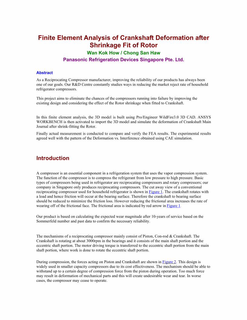
company in Singapore only produces reciprocating compressors. The cut away view of a conventional
reciprocating compressor used for household refrigerator is shown in Figure 1. The crankshaft rotates with
a load and hence friction will occur at the bearing surface. Therefore the crankshaft to bearing surface
should be reduced to minimize the friction loss. However reducing the frictional area increases the rate of
wearing off of the frictional face. The frictional area is indicated by red arrow in Figure 1.
Our product is based on calculating the expected wear magnitude after 10-years of service based on the
Sommerfeld number and past data to confirm the necessary reliability.
The mechanisms of a reciprocating compressor mainly consist of Piston, Con-rod & Crankshaft. The
Crankshaft is rotating at about 3000rpm in the bearings and it consists of the main shaft portion and the
eccentric shaft portion. The motor driving torque is transferred to the eccentric shaft portion from the main
shaft portion, where work is done to rotate the eccentric shaft portion.
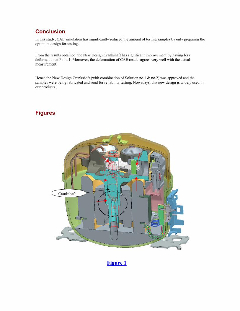
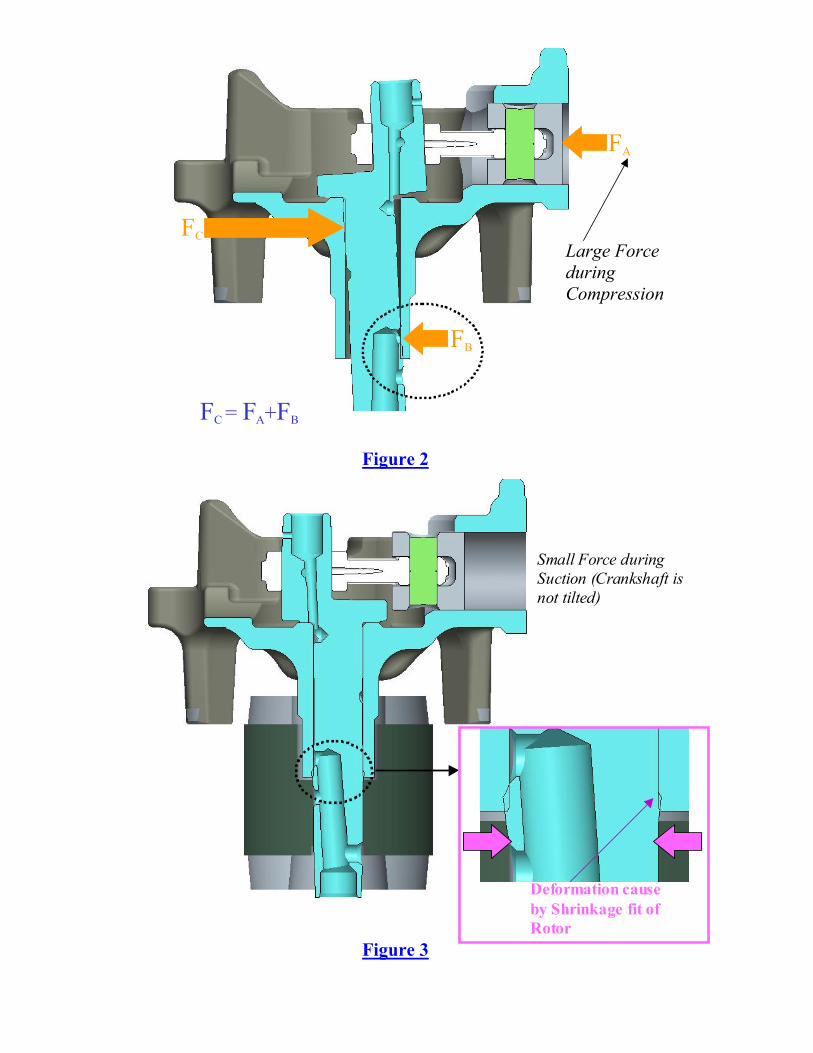
During compression, the forces acting on Piston and Crankshaft are shown in Figure 2. This design is
widely used in smaller capacity compressors due to its cost effectiveness. The mechanism should be able to
withstand up to a certain degree of compression force from the piston during operation. Too much force
may result in deformation of mechanical parts and this will create undesirable wear and tear. In worse
cases, the compressor may cease to operate.

The compression behavior is driven by rotation of the Rotor. In our factory, there are two types of fixing
method of the Rotor to the Crankshaft; one is press-fit type, the other shrinkage fit type. Initially, the press-
fit type was widely adopted for its easy operation with a press machine. But we are shifting to the shrinkage
fit type because the pressing force is loaded only onto the shaft, causing possible deformation of the shaft
and/or the rotor. However, the deformation of Main Journal is unavoidable since the Rotor is shrinkage fit
on the Crankshaft, as shown in Figure 3.
Some minor scratch lines were found on existing Crankshafts after running for long hours in the reliability
test. After investigating, one of the root causes is due to the deformation of Crankshaft Main Journal by
Rotor shrink-fitting as shown in Figure 4. For counter-measure, a proper design change is necessary in
order to reduce this deformation on the Crankshaft so that it can be used in the compressor without
affecting the performance and reliability.
Traditionally, large quantities of samples with different designs are subjected to various tests. In this case,
one of the qualifying tests is that the compressor will be subjected to run for long-term reliability test. After
which, the compressor mechanical parts will be examined for any wear, including the surface profile of the
Crankshaft Main Journal. This is time and resource consuming as sample making and reliability test take
long lead-time and the parts are disposed after these tests.
In this study, CAE approach is used extensively to evaluate the various dimensions of Crankshaft Oil hole,
wall thickness and Oil Pick-up Hole as shown in Figure 5 by using ANSYS simulation software to narrow
down the sample trial effectively.
In addition, to verify the CAE simulation result obtained, experimental measurement results will be use for
verification and comparison purpose.
Finite Element Model
The 3D model with Crankshaft and Rotor was constructed by using Pro/Engineer WildFire3.0 and exported
to ANSYS WORKBENCH. The model is meshed using the default Hex dominant element. By applying
Symmetric Boundary Condition, only half of the model is being simulated. Frictionless contact element is
used between the Crankshaft and Rotor. Fixed displacement is applied on the top surface of Crankshaft to
fully constrain the movement of Crankshaft in all directions. The two lower end point of Rotor is being
constrained to prevent up-down motion of the Rotor. This is due to the model experiencing unstable
condition when the Rotor is not constrained. Refer to Figure 6 for more detailed information.
More than 50 types of New Crankshaft with different parameters are being exported to ANSYS
WORKBENCH for Finite Element Analysis.
Material Properties
The Following material properties were used in the simulation:
Parts Modulus of Elasticity Poisson Ratio
Rotor 200GPa 0.29
Crankshaft 168GPa 0.29

Experimental Measurement
The following illustrates the procedures of the experimental measurement of the deformed Crankshaft.
1. Collect Crankshafts and Rotors with specific range of outer diameter and inner diameter
respectively. This is to create the desire ‘INTERFERENCE DEPTH’ as shown in Figure 6.
2. Prepare Crankshaft with Crank weight to be removed, as shown in Figure 7.
3. Use precision profile measurement equipment to measure the profile of Crankshaft before
shrinking fitting into Rotor.
4. Use induction-heating method to assemble the Rotor onto Crankshaft.
5. Use precision profile measurement equipment to measure the deformation profile of Crankshaft
after shrink fitting Rotor; refer to Figure 7 for experimental data.
Analysis Results & Discussion
From the Simulated results show in Figure 8, there is deformation at Point1, and this is to believe as one of
the root causes of the scratch line. From the contour plot, it is indicated that the amount of deformation is
gradually reduced from point 1 to upper surface of Rotor. To better understanding the deformation amount,
Cylindrical Coordinate System is being set at the center of the Crankshaft. This is to set the deformation
direction to radial direction.
In Figure 9, shows the Crankshaft geometry being studied by ANSYS, it consist of:
1. The distance of Oil Hole edge to Rotor surface.
2. The drill angle of the Oil Pick-up Hole.
3. The wall thickness near the Oil Hole.
4. The diameter of Oil Pick-up Hole.
5. The diameter interference of Crankshaft and Rotor.
After analyzing the simulated results calculated by ANSYS WORKBENCH, a design in which the Oil
Hole is shifted down by 2mm (closer to Rotor top surface) is being finalized. The deformation amount at
Point 1 is reduced significantly. However, to improve the design further, the Oil Hole position is shifted by
90 degree anti-clockwise to move the deformation region (Point 1) away from the large contact pressure
region during compression. This changes are made according to the physics of loading force on Crankshaft
and Bearing. Refer to Figure 10 for the illustration of the counter measure.
From Figure 11, by comparing the actual test result and simulated results, the trend of deformation trend
obtained from simulation agreed very well with the experimental results, although in terms of deformation
amount there were some discrepancies, this is due to the imperfect roundness, cylindricity and tolerances of
the parts. On the other hand, some simplifications and assumptions made in FE model may also affect the
accuracy of simulation. Other factor that leads to the simulated results having higher amount of
deformation is that the actual Rotor used layered material, which was believed to have lower strength
compared with solid parts. However to simulate a Rotor with hundred of layers is very time consuming.
Moreover, these discrepancies does not affect in the design comparison basis.
Conclusion
In this study, CAE simulation has significantly reduced the amount of testing samples by only preparing the
optimum design for testing.
From the results obtained, the New Design Crankshaft has significant improvement by having less
deformation at Point 1. Moreover, the deformation of CAE results agrees very well with the actual
measurement.
Hence the New Design Crankshaft (with combination of Solution no.1 & no.2) was approved and the
samples were being fabricated and send for reliability testing. Nowadays, this new design is widely used in
our products.
Figures
Crankshaft
Figure 1
FA
FB
FC
FC = FA+FB
Small Force during
Suction (Crankshaft is
not tilted)
Deformation cause
by Shrinkage fit of
Rotor
Figure 2
Large Force
during
Compression
Figure 3

Scratch
Line
Oil Hole
Wall thickness
Oil Pick-up Hole
Figure 4
Figure 5

Figure 6
Figure 7
Cut away for
before
measurement
Meshing
Method:
Hex Dominant
assume Homogeneous
material model
Define
Frictionless
Contact
Element on
contact area
Fully Constrained on
TOP Surface
Constrained vertical
movement on this 2 points
Apply Symmetric
boundary
condition on
green area
19
By shorten the
solution time,
only half model
is being used for
simulation.

Figure 8
Figure 9
a°
t
Øc
Øb
d
19
1
4
2
3
5
a°
t
Øc
Øb
d
19
1
4
2
3
5
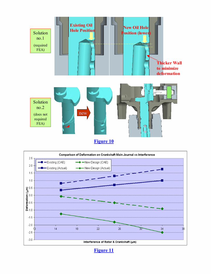
Existing Oil
Hole PositionNew Oil Hole
Position (lower)
Thicker Wall
to minimize
deformation
Solution
no.1
(required
FEA)
new
Solution
no.2
(does not
required
FEA)
Figure 10
Figure 11