Final TGDC VVSG Recommendations to the EAC Recommendations to the EAC Voluntary Voting System...
598
VVSG Recommendations to the EAC Voluntary Voting System Guidelines Recommendations to the Election Assistance Commission AUGUST 31, 2007 Prepared at the Direction of the Technical Guidelines Development Committee August 2007
-
Upload
truongkhanh -
Category
Documents
-
view
219 -
download
0
Transcript of Final TGDC VVSG Recommendations to the EAC Recommendations to the EAC Voluntary Voting System...
VVSG Recommenda t i ons
t o t he EAC
Voluntary Voting System Guidelines Recommendations to the Election Assistance Commission A U G U S T 3 1 , 2 0 0 7
Prepared at the Direction of the
Technical Guidelines Development Committee
August 2007

ii
Tips for navigating this document in PDF readers This document contains numerous hypertext links and ‘bookmarks’ and by using these features, you can more easily navigate this document and readily locate information. The steps below will help you set up your PDF reader to better navigate this (and other PDF documents) and will help you better understand this document’s navigation features.
1. Make sure the Navigation toolbar is viewable on the menu of your PDF reader. To display the Navigation toolbar, typically from the View menu, select Toolbars and Navigation. You should then see two sets of buttons on the navigation toolbar:
a. Previous View, Next View buttons for switching between the previous and next pages that you have viewed, useful when clicking on a link that takes you to a new page and then returning back to the previous page you were viewing, similar to using links in a web browser and clicking on the browser’s Back and Next buttons (in some versions of PDF readers, the left arrow “←” and right arrow “→” keys on the keyboard also work for Previous, Next View), and
b. Previous Page, Next Page buttons for advancing to the next or previous consecutive pages in the document.
If the buttons for Previous and Next View above are still not visible on the menu, it is because Adobe’s reader sometimes has the buttons disabled on the navigation toolbar. To enable them, you need to select the appropriate option for Customizing Toolbars, and then check the boxes for these buttons to be displayed on the navigation toolbar.
2. There are bookmarks in the left window of the PDF reader display that can be used as a hypertext-linked table of contents to sections within this document.
a. If the left window of bookmarks is not displayed, select the Bookmarks tab usually located at the left of the main display window.
b. To see sublevel bookmarks, expand the list by clicking the plus (+) next to the bookmark. To see only the top level bookmarks, collapse the list by clicking the minus (-) next to the bookmark.
c. To go to the section indicated by the bookmark, click the bookmark. Use the Previous View, Next View buttons on the Navigation toolbar for switching between pages you have viewed.
3. You can use the various hypertext links in the document to specific sections, specific requirements, definitions, and references/URLs. URLs are underlined using the color ‘blue,’ e.g., http://www.eac.gov/vvsg_intro.htm. Links to definitions and references are less obvious and have a dotted underline, e.g., audio-tactile interface, because they are used frequently throughout the text.
4. There is a Summary of Requirements containing links to each requirement (the link to this summary is also on the bookmarks window of the PDF reader display); the links are located in the page numbers for the requirements but are not displayed in blue or underlined. The mouse cursor will change to, e.g., a pointer, when you mouse over these links. Links in the Table of Contents work the same way.

iii
Acknowledgements In September 2005, the Technical Guidelines Development Committee (TGDC) began public deliberations on a second set of recommendations for Voluntary Voting System Guidelines. This document is the result of their leadership, technical direction, and collaborative efforts with researchers at the National Institute of Standards and Technology (NIST). Dr. William Jeffrey, Chair of the TGDC Director of the National Institute of Standards and Technology (NIST) Gaithersburg, MD Representing the EAC Standards Board: John Gale Alice Miller Nebraska Secretary of State Director of Elections-District of Columbia Lincoln, NE Washington, DC Representing the EAC Board of Advisors: Helen Purcell Maricopa County Recorder, Phoenix, AZ Representing the Architectural and Transportation Barrier, and Compliance Board (Access Board): Tricia Mason Philip Pearce Arlington, VA College Station, TX Representing the American National Standards Institute (ANSI): Dr. David Wagner Associate Professor, Computer Science Division University of California at Berkeley, Berkeley, CA Representing the National Association of State Election Directors (NASED): Dr. Britain Williams Paul Miller Retired professor, Kennesaw State Voting Systems Manager, SSO Tucker, GA Olympia, WA Individuals with technical and scientific expertise relating to voting systems and equipment: Patrick Gannon Whitney Quesenbery President and CEO, OASIS past President-Usability Professionals' Billerica, MA Association, High Bridge, NJ Dr. Ronald Rivest Dr. Daniel Schutzer Professor, Department of Electrical Executive Director Engineering and Computer Science Financial Services Technology MIT, Cambridge, MA Consortium, New York, NY Past Members of the TGDC: Steven Berger – Representing the Institute of Electrical and Electronics Engineers (IEEE) Anne Caldas – Representing ANSI Paul Craft – Representing NASED Donetta Davidson - Representing the Standards Board Dr. James Elekes – Representing the Access Board Dr. James Harding – Representing the Access Board David Karmol – Representing ANSI Sharon Turner-Buie – Representing the Board of Advisors

iv
i
Table of Contents To jump to specific sections of this document, click on the section’s page number (see Tips for navigating this document in PDF readers).
Introduction to the VVSG
Chapter 1: Overview ........................................................................... 1-1
1.1 Purpose.................................................................................................. 1-1
1.2 Scope .....................................................................................................1-1
1.3 Audience ................................................................................................1-2
1.4 Structure................................................................................................ 1-2
Chapter 2: Introduction to New and Expanded Material ............................ 2-3
2.1 The New Structure of the VVSG..............................................................2-3 2.1.1 VVSG Standards Architecture..............................................................................................2-4 2.1.2 Voting System and Device Classes .....................................................................................2-4 2.1.3 Requirements Structure........................................................................................................2-5 2.1.4 Strict Terminology.................................................................................................................2-6
2.2 Usability Performance Requirements .....................................................2-7
2.3 Expanded Usability and Accessibility Coverage ......................................2-8
2.4 Software Independence .........................................................................2-9 2.4.1 Independent voter-verifiable records ..................................................................................2-9 2.4.2 The Innovation Class ..........................................................................................................2-10
2.5 Open-Ended Vulnerability Testing ........................................................2-11
2.6 Expanded Security Coverage................................................................2-11
2.7 Treatment of COTS in Voting System Testing .......................................2-12
2.8 End-to-End Testing............................................................................... 2-12
2.9 Reliability ............................................................................................. 2-13
2.10 Expanded Core Requirements Coverage...............................................2-13
Chapter 3: VVSG Background ............................................................. 3-15
3.1 Earlier NIST Involvement.....................................................................3-15
3.2 The 1990 VSS....................................................................................... 3-15
3.3 The 2002 VSS....................................................................................... 3-16
3.4 HAVA and VVSG 2005...........................................................................3-16

ii
3.5 Relationship of HAVA and the VVSG .....................................................3-17
Chapter 4: Using This Document ......................................................... 4-19
4.1 Requirements Language and Structure ................................................4-19
4.2 The Conformance Clause and Classes...................................................4-20 4.2.1 Inheritance in device classes .............................................................................................4-21 4.2.2 Instantiated device classes ................................................................................................4-22 4.2.3 General device class usage in requirements....................................................................4-22
4.3 Navigating Through Requirements.......................................................4-24
Part 1: Equipment Requirements
Chapter 1: Introduction ....................................................................... 1-1
1.1 Changes from VVSG 2005 and Previous Versions of the Standards ........1-1 1.1.1 Conformance clause .............................................................................................................1-1 1.1.2 Usability Performance Benchmarks ....................................................................................1-2 1.1.3 Security requirements...........................................................................................................1-2 1.1.4 Epollbooks and ballot activation .........................................................................................1-3 1.1.5 Common data format ............................................................................................................1-3 1.1.6 Core requirements.................................................................................................................1-4 1.1.7 Coding conventions..............................................................................................................1-5 1.1.8 Applicability to COTS and borderline COTS products.......................................................1-6 1.1.9 Reference models..................................................................................................................1-6 1.1.10 Deletions ................................................................................................................................1-7 1.1.11 Supplemental Guidance........................................................................................................1-8
Chapter 2: Conformance Clause ............................................................ 2-9
2.1 Structure of Requirements .....................................................................2-9
2.2 Normative Language ............................................................................2-10
2.3 Conformance Designations...................................................................2-10
2.4 Implementation Statement ..................................................................2-10
2.5 Classes................................................................................................. 2-11 2.5.1 Voting device terminology..................................................................................................2-11 2.5.2 Classes overview.................................................................................................................2-12 2.5.3 Classes identified in implementation statement ..............................................................2-14 2.5.4 Semantics of classes ..........................................................................................................2-18
2.6 Extensions............................................................................................ 2-20
2.7 Software Independence .......................................................................2-20 2.7.1 Achieving software independence via independent voter-verifiable records................2-20 2.7.2 Innovation class submissions ...........................................................................................2-21

iii
Chapter 3: Usability, Accessibility, and Privacy Requirements .................. 3-25
3.1 Overview..............................................................................................3-25 3.1.1 Purpose................................................................................................................................3-25 3.1.2 Special terminology ............................................................................................................3-26 3.1.3 Interaction of usability and accessibility requirements ...................................................3-27
3.2 General Usability Requirements ...........................................................3-27 3.2.1 Performance Requirements................................................................................................3-28 3.2.2 Functional capabilities........................................................................................................3-31 3.2.3 Privacy..................................................................................................................................3-36 3.2.4 Cognitive issues..................................................................................................................3-38 3.2.5 Perceptual issues................................................................................................................3-43 3.2.6 Interaction issues................................................................................................................3-46 3.2.7 Alternative languages .........................................................................................................3-50 3.2.8 Usability for poll workers ...................................................................................................3-52
3.3 Accessibility requirements ...................................................................3-55 3.3.1 General .................................................................................................................................3-56 3.3.2 Low vision............................................................................................................................3-58 3.3.3 Blindness .............................................................................................................................3-60 3.3.4 Dexterity ...............................................................................................................................3-65 3.3.5 Mobility.................................................................................................................................3-67 3.3.6 Hearing.................................................................................................................................3-71 3.3.7 Cognition..............................................................................................................................3-72 3.3.8 English proficiency .............................................................................................................3-72 3.3.9 Speech..................................................................................................................................3-73
Chapter 4: Security and Audit Architecture ........................................... 4-75
4.1 Overview..............................................................................................4-75
4.2 Requirements for Supporting Auditing .................................................4-75 4.2.1 Pollbook audit......................................................................................................................4-76 4.2.2 Hand audit of IVVR record..................................................................................................4-77 4.2.3 Ballot count and vote total audit........................................................................................4-79 4.2.4 Additional behavior to support auditing for accessible IVVR voting systems ..............4-80
4.3 Electronic Records................................................................................ 4-81 4.3.1 Records produced by voting devices................................................................................4-82 4.3.2 Records produced by tabulators .......................................................................................4-83 4.3.3 Records produced by the EMS ..........................................................................................4-86 4.3.4 Digital signature verification ..............................................................................................4-88 4.3.5 Ballot counter ......................................................................................................................4-89
4.4 Independent Voter-Verifiable Records .................................................4-89 4.4.1 General requirements .........................................................................................................4-90 4.4.2 VVPAT ..................................................................................................................................4-96 4.4.3 PCOS systems...................................................................................................................4-107

iv
Chapter 5: General Security Requirements ..........................................5-109
5.1 Cryptography ..................................................................................... 5-109 5.1.1 General cryptographic implementation...........................................................................5-110 5.1.2 Digital signatures for election records............................................................................5-112 5.1.3 Key management for signature keys ...............................................................................5-114 5.1.4 Election Signature Key (ESK)...........................................................................................5-118
5.2 Setup Inspection................................................................................ 5-120 5.2.1 Voting device software inspection ..................................................................................5-120 5.2.2 Voting device election information inspection ...............................................................5-123 5.2.3 Voting equipment properties inspection.........................................................................5-124
5.3 Software Installation ......................................................................... 5-127
5.4 Access Control.................................................................................... 5-131 5.4.1 General access control .....................................................................................................5-132 5.4.2 Access control identification ...........................................................................................5-136 5.4.3 Access control authentication .........................................................................................5-139 5.4.4 Access control authorization ...........................................................................................5-143
5.5 System Integrity Management ........................................................... 5-145 5.5.1 Electronic devices .............................................................................................................5-145 5.5.2 Removable media ..............................................................................................................5-147 5.5.3 Backup and recovery ........................................................................................................5-147 5.5.4 Malicious software protection..........................................................................................5-149
5.6 Communication Security .................................................................... 5-151 5.6.1 Physical communication security....................................................................................5-151 5.6.2 Data transmission security...............................................................................................5-154 5.6.3 Application communication security...............................................................................5-156
5.7 System Event Logging........................................................................ 5-159 5.7.1 General system event logging..........................................................................................5-159 5.7.2 System event log management ........................................................................................5-165 5.7.3 System event log protection ............................................................................................5-170
5.8 Physical Security for Voting Devices ..................................................5-171 5.8.1 Unauthorized physical access .........................................................................................5-171 5.8.2 Physical port and access least functionality ..................................................................5-172 5.8.3 Voting device boundary protection .................................................................................5-172 5.8.4 Information flow ................................................................................................................5-173 5.8.5 Door cover and panel security .........................................................................................5-174 5.8.6 Secure ballot box ..............................................................................................................5-175 5.8.7 Secure physical lock and key...........................................................................................5-175 5.8.8 Physical encasing lock .....................................................................................................5-176 5.8.9 Power supply.....................................................................................................................5-176
Chapter 6: General Core Requirements ...............................................6-177
6.1 General Design Requirements ............................................................ 6-177

v
6.2 Voting Variations ............................................................................... 6-179
6.3 Hardware and Software Performance, General Requirements............6-180 6.3.1 Reliability ...........................................................................................................................6-180 6.3.2 Accuracy/error rate ...........................................................................................................6-187 6.3.3 Misfeed rate .......................................................................................................................6-188 6.3.4 Electromagnetic Compatibility (EMC) immunity.............................................................6-188 6.3.5 Electromagnetic Compatibility (EMC) emission limits...................................................6-198 6.3.6 Other requirements ...........................................................................................................6-200
6.4 Workmanship ..................................................................................... 6-201 6.4.1 Software engineering practices .......................................................................................6-201 6.4.2 Quality assurance and configuration management .......................................................6-221 6.4.3 General build quality.........................................................................................................6-224 6.4.4 Durability............................................................................................................................6-225 6.4.5 Maintainability ...................................................................................................................6-225 6.4.6 Temperature and humidity ...............................................................................................6-227 6.4.7 Equipment transportation and storage ...........................................................................6-227
6.5 Archival Requirements ....................................................................... 6-229 6.5.1 Archivalness of media.......................................................................................................6-229 6.5.2 Procedures required for correct system functioning.....................................................6-230 6.5.3 Period of retention (informative) ......................................................................................6-230
6.6 Integratability and Data Export/Interchange ....................................6-231
6.7 Procedures required for correct system functioning ..........................6-235
Chapter 7: Requirements by Voting Activity .........................................7-237
7.1 Election Programming........................................................................ 7-237
7.2 Ballot Preparation, Formatting, and Production .................................7-241 7.2.1 Procedures required for correct system functioning.....................................................7-244
7.3 Equipment Setup for Security and Integrity .......................................7-245 7.3.1 Logic and accuracy testing ..............................................................................................7-245
7.4 Opening Polls ..................................................................................... 7-248
7.5 Casting............................................................................................... 7-249 7.5.1 Issuance of voting credentials and ballot activation......................................................7-249 7.5.2 General voting functionality .............................................................................................7-259 7.5.3 Voting variations ...............................................................................................................7-259 7.5.4 Recording votes ................................................................................................................7-264 7.5.5 Redundant records ...........................................................................................................7-266 7.5.6 Respecting limits...............................................................................................................7-267 7.5.7 Procedures required for correct system functioning.....................................................7-267
7.6 Closing Polls....................................................................................... 7-268 7.6.1 Procedures required for correct system functioning.....................................................7-270
7.7 Counting ............................................................................................ 7-270

vi
7.7.1 Integrity ..............................................................................................................................7-270 7.7.2 Voting variations ...............................................................................................................7-271 7.7.3 Ballot separation ...............................................................................................................7-277 7.7.4 Misfed ballots ....................................................................................................................7-279 7.7.5 Accuracy ............................................................................................................................7-280 7.7.6 Consolidation ....................................................................................................................7-285 7.7.7 Procedures required for correct system functioning.....................................................7-285
7.8 Reporting ........................................................................................... 7-285 7.8.1 General reporting functionality ........................................................................................7-286 7.8.2 Audit, status, and readiness reports ...............................................................................7-286 7.8.3 Vote data reports...............................................................................................................7-289 7.8.4 Procedures required for correct system functioning.....................................................7-297
Chapter 8: Reference Models .............................................................8-299
8.1 Process Model (informative) .............................................................. 8-299 8.1.1 Introduction .......................................................................................................................8-299 8.1.2 Diagrams............................................................................................................................8-301 8.1.3 Translation of diagrams....................................................................................................8-309
8.2 Vote-Capture Device State Model (informative) .................................8-315
8.3 Logic Model (normative) .................................................................... 8-316 8.3.1 Domain of discourse.........................................................................................................8-317 8.3.2 General constraints...........................................................................................................8-319 8.3.3 Cumulative voting .............................................................................................................8-320 8.3.4 N-of-M contests (including 1-of-M) ..................................................................................8-320
Part 2: Documentation Requirements
Chapter 1: Introduction ....................................................................... 1-1
1.1 Changes from VVSG 2005 and Previous Versions of the Standards ........1-1 1.1.1 Separation of requirements on Voting Equipment User Documentation from
requirements on Technical Data Package ..........................................................................1-2 1.1.2 Changes in TDP content .......................................................................................................1-2 1.1.3 Revisions to test lab reports ................................................................................................1-2 1.1.4 Public Information Package (PIP) ........................................................................................1-2
Chapter 2: Quality Assurance and Configuration Management Data Package (manufacturer) ................................................................... 2-5
2.1 Quality and Configuration Management Manual .....................................2-5
Chapter 3: Technical Data Package (manufacturer)................................ 3-11
3.1 Scope ................................................................................................... 3-11 3.1.1 Content and format .............................................................................................................3-11
vii
3.1.2 Other uses for documentation ...........................................................................................3-13 3.1.3 Protection of proprietary information................................................................................3-13
3.2 Implementation Statement ..................................................................3-14
3.3 System Hardware Specification............................................................3-15 3.3.1 System hardware characteristics ......................................................................................3-15 3.3.2 Design and construction ....................................................................................................3-16 3.3.3 Hardwired logic ...................................................................................................................3-17
3.4 Application Logic Design and Specification...........................................3-17 3.4.1 Purpose and scope .............................................................................................................3-17 3.4.2 Applicable documents ........................................................................................................3-18 3.4.3 Application logic overview .................................................................................................3-18 3.4.4 Application logic standards and conventions ..................................................................3-19 3.4.5 Application logic operating environment..........................................................................3-19 3.4.6 Application logic functional specification.........................................................................3-21 3.4.7 Programming specifications ..............................................................................................3-22 3.4.8 System database .................................................................................................................3-26 3.4.9 Interfaces .............................................................................................................................3-27 3.4.10 Appendices ..........................................................................................................................3-29
3.5 System Security Specifications.............................................................3-30 3.5.1 General .................................................................................................................................3-30 3.5.2 Access Control ....................................................................................................................3-31 3.5.3 System Event Logging........................................................................................................3-32 3.5.4 Software Installation ...........................................................................................................3-33 3.5.5 Physical Security.................................................................................................................3-36 3.5.6 System Integrity Management............................................................................................3-37 3.5.7 Setup Inspection .................................................................................................................3-37 3.5.8 Cryptography.......................................................................................................................3-40
3.6 System Test Specification ....................................................................3-40 3.6.1 Development test specifications........................................................................................3-40 3.6.2 System test specifications .................................................................................................3-41
3.7 System Change Notes .......................................................................... 3-41
3.8 Configuration for Testing .....................................................................3-42
Chapter 4: Voting Equipment User Documentation (manufacturer)........... 4-45
4.1 System Overview .................................................................................4-45 4.1.1 System description .............................................................................................................4-46 4.1.2 System performance ...........................................................................................................4-47
4.2 System Functionality Description .........................................................4-48
4.3 System Security Specification ..............................................................4-48 4.3.1 Access control.....................................................................................................................4-48 4.3.2 System event logging .........................................................................................................4-50 4.3.3 Software installation ...........................................................................................................4-50
viii
4.3.4 Physical security .................................................................................................................4-53 4.3.5 Setup inspection .................................................................................................................4-54 4.3.6 Audit .....................................................................................................................................4-58
4.4 System Operations Manual................................................................... 4-59 4.4.1 Introduction .........................................................................................................................4-60 4.4.2 Operational environment ....................................................................................................4-60 4.4.3 System installation and test specification ........................................................................4-61 4.4.4 Operational features............................................................................................................4-62 4.4.5 Operating procedures.........................................................................................................4-62 4.4.6 Documentation for poll workers ........................................................................................4-64 4.4.7 Operations support .............................................................................................................4-64 4.4.8 Transportation and storage................................................................................................4-64 4.4.9 Appendices ..........................................................................................................................4-65
4.5 System Maintenance Manual ................................................................4-65 4.5.1 Introduction .........................................................................................................................4-66 4.5.2 Maintenance procedures ....................................................................................................4-66 4.5.3 Maintenance equipment......................................................................................................4-68 4.5.4 Parts and materials .............................................................................................................4-68 4.5.5 Maintenance facilities and support....................................................................................4-70 4.5.6 Appendices ..........................................................................................................................4-70
4.6 Personnel Deployment and Training Requirements..............................4-71 4.6.1 Personnel .............................................................................................................................4-71 4.6.2 Training ................................................................................................................................4-71
Chapter 5: Test Plan (test lab) ............................................................ 5-73
5.1 Test plan contents................................................................................ 5-73
Chapter 6: Test Report (test lab)......................................................... 6-77
6.1 Test report contents.............................................................................6-77
Chapter 7: Public Information Package (test lab) ................................... 7-83
7.1 Public Information Package contents...................................................7-83
Part 3: Testing Requirements
Chapter 1: Introduction ....................................................................... 1-1
1.1 Changes from VVSG 2005 and Previous Versions of the Standards ........1-1 1.1.1 Reorganization of testing-related material..........................................................................1-1 1.1.2 Applicability to COTS and borderline COTS products.......................................................1-1 1.1.3 New and revised inspections ...............................................................................................1-2 1.1.4 New and revised test methods.............................................................................................1-3

ix
Chapter 2: Conformity Assessment Process............................................. 2-5
2.1 Overview................................................................................................2-5
2.2 Scope of Assessment..............................................................................2-6
2.3 Testing Sequence ...................................................................................2-7
2.4 Pre-Test Activities..................................................................................2-7 2.4.1 Initiation of testing ................................................................................................................2-8 2.4.2 Pre-test preparation ..............................................................................................................2-8 2.4.3 Initial system build by test lab ...........................................................................................2-10
2.5 Testing ................................................................................................. 2-22 2.5.1 Test plan...............................................................................................................................2-22 2.5.2 Test conditions....................................................................................................................2-23 2.5.3 Test fixtures .........................................................................................................................2-23 2.5.4 Test data requirements .......................................................................................................2-24 2.5.5 Test practices ......................................................................................................................2-25
2.6 Post-Test Activities ..............................................................................2-27 2.6.1 Voting system software version recommended for certification ....................................2-27 2.6.2 Software distribution requirements for repositories, test labs, and manufacturers .....2-28 2.6.3 Final test report ...................................................................................................................2-37
Chapter 3: Introduction to General Testing Approaches .......................... 3-39
3.1 Inspection............................................................................................ 3-39
3.2 Functional Testing................................................................................3-39
3.3 Performance Testing (Benchmarking)..................................................3-40
3.4 Vulnerability Testing ............................................................................3-40
3.5 Interoperability Testing .......................................................................3-40
Chapter 4: Documentation and Design Reviews (Inspections).................. 4-43
4.1 Initial Review of Documentation ..........................................................4-43
4.2 Physical Configuration Audit ................................................................4-44
4.3 Verification of Design Requirements ....................................................4-45
4.4 Manufacturer Practices for Quality Assurance and Configuration Management ........................................................................................ 4-46
4.4.1 Examination of quality assurance and configuration management data package........4-46 4.4.2 Examination of voting systems submitted for testing .....................................................4-46
4.5 Source Code Review.............................................................................4-47 4.5.1 Workmanship.......................................................................................................................4-47 4.5.2 Security ................................................................................................................................4-48
4.6 Logic Verification .................................................................................4-48
x
Chapter 5: Test Methods .................................................................... 5-51
5.1 Hardware ............................................................................................. 5-51 5.1.1 Electromagnetic compatibility (EMC) immunity ...............................................................5-51 5.1.2 Electromagnetic compatibility (EMC) emissions limits ...................................................5-59 5.1.3 Other (non-EMC) industry-mandated requirements.........................................................5-60 5.1.4 Non-operating environmental testing................................................................................5-61 5.1.5 Operating environmental testing .......................................................................................5-62
5.2 Functional Testing................................................................................5-63 5.2.1 General guidelines ..............................................................................................................5-64 5.2.2 Structural coverage (white-box testing) ............................................................................5-65 5.2.3 Functional coverage (black-box testing)...........................................................................5-66
5.3 Benchmarks ......................................................................................... 5-73 5.3.1 General method ...................................................................................................................5-73 5.3.2 Critical values ......................................................................................................................5-75 5.3.3 Reliability .............................................................................................................................5-81 5.3.4 Accuracy ..............................................................................................................................5-82 5.3.5 Misfeed rate .........................................................................................................................5-83
5.4 Open-Ended Vulnerability Testing ........................................................5-85 5.4.1 OEVT scope and priorities..................................................................................................5-85 5.4.2 OEVT resources and level of effort....................................................................................5-87 5.4.3 Rules of engagement ..........................................................................................................5-89 5.4.4 Fail criteria ...........................................................................................................................5-90 5.4.5 OEVT reporting requirements ............................................................................................5-91 5.4.6 VSTL response to OEVT .....................................................................................................5-92
Appendix A: Definitions of Words with Special Meanings
Appendix B: References and End Notes

xi
Summary of Requirements This is a summary listing of all requirements in the VVSG. The requirements and their sub-requirements are designated by the “ ” and “ ” characters, respectively. To jump to specific requirements, click on the page numbers, e.g., to jump to Part 1 Requirement 2.4-A, click on its page number 2-3 (see also Tips for navigating this document in PDF readers).
Introduction to the VVSG
Chapter 1: Overview ........................................................................... 1-1
1.1 Purpose.................................................................................................. 1-1
1.2 Scope .....................................................................................................1-1
1.3 Audience ................................................................................................1-2
1.4 Structure................................................................................................ 1-2
Chapter 2: Introduction to New and Expanded Material ............................ 2-3
2.1 The New Structure of the VVSG..............................................................2-3 2.1.1 VVSG Standards Architecture..............................................................................................2-4 2.1.2 Voting System and Device Classes .....................................................................................2-4 2.1.3 Requirements Structure........................................................................................................2-5 2.1.4 Strict Terminology.................................................................................................................2-6
2.2 Usability Performance Requirements .....................................................2-7
2.3 Expanded Usability and Accessibility Coverage ......................................2-8
2.4 Software Independence .........................................................................2-9 2.4.1 Independent voter-verifiable records ..................................................................................2-9 2.4.2 The Innovation Class ..........................................................................................................2-10
2.5 Open-Ended Vulnerability Testing ........................................................2-11
2.6 Expanded Security Coverage................................................................2-11
2.7 Treatment of COTS in Voting System Testing .......................................2-12
2.8 End-to-End Testing............................................................................... 2-12
2.9 Reliability ............................................................................................. 2-13
2.10 Expanded Core Requirements Coverage...............................................2-13
Chapter 3: VVSG Background ............................................................. 3-15
3.1 Earlier NIST Involvement.....................................................................3-15
3.2 The 1990 VSS....................................................................................... 3-15
xii
3.3 The 2002 VSS....................................................................................... 3-16
3.4 HAVA and VVSG 2005...........................................................................3-16
3.5 Relationship of HAVA and the VVSG .....................................................3-17
Chapter 4: Using This Document ......................................................... 4-19
4.1 Requirements Language and Structure ................................................4-19 3.3.3-C Audio Features and characteristics ...................................................................... 4-19
3.3.3-C.1 Standard connector ....................................................................................... 4-20 4.2 The Conformance Clause and Classes...................................................4-20
4.2.1 Inheritance in device classes .............................................................................................4-21 4.2.2 Instantiated device classes ................................................................................................4-22 4.2.3 General device class usage in requirements....................................................................4-22
4.2-A Storage between elections ...................................................................................... 4-23 4.2-B Ballot secrecy.......................................................................................................... 4-23
4.3 Navigating Through Requirements.......................................................4-24
Part 1: Equipment Requirements
Chapter 1: Introduction ....................................................................... 1-1
1.1 Changes from VVSG 2005 and Previous Versions of the Standards ........1-1 1.1.1 Conformance clause .............................................................................................................1-1 1.1.2 Usability Performance Benchmarks ....................................................................................1-2 1.1.3 Security requirements...........................................................................................................1-2 1.1.4 Epollbooks and ballot activation .........................................................................................1-3 1.1.5 Common data format ............................................................................................................1-3 1.1.6 Core requirements.................................................................................................................1-4 1.1.7 Coding conventions..............................................................................................................1-5 1.1.8 Applicability to COTS and borderline COTS products.......................................................1-6 1.1.9 Reference models..................................................................................................................1-6 1.1.10 Deletions ................................................................................................................................1-7 1.1.11 Supplemental Guidance........................................................................................................1-8
Chapter 2: Conformance Clause ............................................................ 2-9
2.1 Structure of Requirements .....................................................................2-9
2.2 Normative Language ............................................................................2-10
2.3 Conformance Designations...................................................................2-10
2.4 Implementation Statement ..................................................................2-10 2.4-A Implementation statement ....................................................................................... 2-11
2.5 Classes................................................................................................. 2-11 2.5.1 Voting device terminology..................................................................................................2-11 2.5.2 Classes overview.................................................................................................................2-12

xiii
2.5.3 Classes identified in implementation statement ..............................................................2-14 2.5.3-A Implementation statement, system classes.......................................................... 2-14 2.5.3-B Implementation statement, device classes........................................................... 2-15 2.5.3-C Implementation statement, voting variations documentation references .............. 2-15
2.5.3.1 Supported voting variations (system-level) ........................................................................... 2-15 2.5.3.2 Supported voting variations (device-level) ............................................................................ 2-16 2.5.3.3 Voting device classes ........................................................................................................... 2-17 2.5.4 Semantics of classes ..........................................................................................................2-18
2.6 Extensions............................................................................................ 2-20 2.6-A Extensions shall not break conformance ................................................................. 2-20
2.7 Software Independence .......................................................................2-20 2.7-A Software independence........................................................................................... 2-20
2.7.1 Achieving software independence via independent voter-verifiable records................2-20 2.7.1-A IVVR, software independence .............................................................................. 2-21 2.7.1-B IVVR, requires IVVR vote-capture device ............................................................ 2-21
2.7.2 Innovation class submissions ...........................................................................................2-21 2.7.2-A Innovation class, submission procedures............................................................. 2-22 2.7.2-B Innovation class, identification of innovativeness ................................................. 2-23 2.7.2-C Innovation class, new device class....................................................................... 2-23
2.7.2-C.1 Innovative class, device class submission..................................................... 2-23 2.7.2-C.2 Innovation class, device class identification of requirements ......................... 2-23
Chapter 3: Usability, Accessibility, and Privacy Requirements .................. 3-25
3.1 Overview..............................................................................................3-25 3.1.1 Purpose................................................................................................................................3-25 3.1.2 Special terminology ............................................................................................................3-26 3.1.3 Interaction of usability and accessibility requirements ...................................................3-27
3.2 General Usability Requirements ...........................................................3-27 3.2.1 Performance Requirements................................................................................................3-28 3.2.1.1 Overall performance metrics ................................................................................................ 3-29
3.2.1.1-A Total completion performance........................................................................... 3-30 3.2.1.1-B Perfect ballot performance ................................................................................ 3-30 3.2.1.1-C Voter inclusion performance.............................................................................. 3-30 3.2.1.1-D Usability metrics from the Voting Performance Protocol ................................... 3-30
3.2.1.1-D.1 Effectiveness metrics for usability............................................................... 3-30 3.2.1.1-D.2 Voting session time..................................................................................... 3-31 3.2.1.1-D.3 Average voter confidence ........................................................................... 3-31
3.2.1.2 Manufacturer testing............................................................................................................. 3-31 3.2.1.2-A Usability testing by manufacturer for general population ................................... 3-31
3.2.2 Functional capabilities........................................................................................................3-31 3.2.2-A Notification of effect of overvoting ........................................................................ 3-32 3.2.2-B Undervoting to be permitted ................................................................................. 3-32 3.2.2-C Correction of ballot ............................................................................................... 3-32 3.2.2-D Notification of ballot casting.................................................................................. 3-32
3.2.2.1 Editable interfaces................................................................................................................ 3-33 3.2.2.1-A Prevention of overvotes..................................................................................... 3-33 3.2.2.1-B Warning of undervotes ...................................................................................... 3-33 3.2.2.1-C Independent correction of ballot ........................................................................ 3-33 3.2.2.1-D Ballot editing per contest ................................................................................... 3-33 3.2.2.1-E Contest navigation............................................................................................. 3-34 3.2.2.1-F Notification of ballot casting failure (DRE) ......................................................... 3-34
xiv
3.2.2.2 Non-Editable interfaces ........................................................................................................ 3-34 3.2.2.2-A Notification of overvoting ................................................................................... 3-35 3.2.2.2-B Notification of undervoting................................................................................. 3-35 3.2.2.2-C Notification of blank ballots................................................................................ 3-35 3.2.2.2-D Ballot correction or submission following notification......................................... 3-35 3.2.2.2-E Handling of marginal marks............................................................................... 3-36 3.2.2.2-F Notification of ballot casting failure (PCOS)....................................................... 3-36
3.2.3 Privacy..................................................................................................................................3-36 3.2.3.1 Privacy at the polls ............................................................................................................... 3-36
3.2.3.1-A System support of privacy ................................................................................. 3-36 3.2.3.1-A.1 Visual privacy.............................................................................................. 3-37 3.2.3.1-A.2 Auditory privacy .......................................................................................... 3-37 3.2.3.1-A.3 Privacy of warnings..................................................................................... 3-37 3.2.3.1-A.4 No receipts.................................................................................................. 3-38
3.2.3.2 No recording of alternative format usage.............................................................................. 3-38 3.2.3.2-A No recording of alternative languages............................................................... 3-38 3.2.3.2-B No Recording of Accessibility Features............................................................. 3-38
3.2.4 Cognitive issues..................................................................................................................3-38 3.2.4-A Completeness of instructions ............................................................................... 3-38 3.2.4-B Availability of assistance from the system ............................................................ 3-39 3.2.4-C Plain Language .................................................................................................... 3-39
3.2.4-C.1 Clarity of warnings ......................................................................................... 3-39 3.2.4-C.2 Context before action..................................................................................... 3-40 3.2.4-C.3 Simple vocabulary ......................................................................................... 3-40 3.2.4-C.4 Start each instruction on a new line ............................................................... 3-40 3.2.4-C.5 Use of positive ............................................................................................... 3-40 3.2.4-C.6 Use of imperative voice ................................................................................. 3-41 3.2.4-C.7 Gender-based pronouns................................................................................ 3-41 3.2.4-D No bias among choices ........................................................................................ 3-41 3.2.4-E Ballot design......................................................................................................... 3-41
3.2.4-E.1 Contests split among pages or columns ........................................................ 3-41 3.2.4-E.2 Indicate maximum number of candidates ...................................................... 3-42 3.2.4-E.3 Consistent representation of candidate selection........................................... 3-42 3.2.4-E.4 Placement of instructions............................................................................... 3-42 3.2.4-F Conventional use of color ..................................................................................... 3-42 3.2.4-G Icons and language.............................................................................................. 3-43
3.2.5 Perceptual issues................................................................................................................3-43 3.2.5-A Screen flicker ....................................................................................................... 3-43 3.2.5-B Resetting of adjustable aspects at end of session ............................................... 3-43 3.2.5-C Ability to reset to default values............................................................................ 3-44 3.2.5-D Minimum font size ................................................................................................ 3-44 3.2.5-E Available font sizes............................................................................................... 3-44 3.2.5-F Use of sans serif font............................................................................................ 3-44 3.2.5-G Legibility of paper ballots and verification records................................................ 3-45
3.2.5-G.1 Legibility via font size..................................................................................... 3-45 3.2.5-G.2 Legibility via magnification............................................................................. 3-45 3.2.5-H Contrast Ratio ...................................................................................................... 3-45 3.2.5-I High contrast for electronic displays ...................................................................... 3-46 3.2.5-J Accommodation for color blindness ...................................................................... 3-46 3.2.5-K No reliance solely on color ................................................................................... 3-46
3.2.6 Interaction issues................................................................................................................3-46 3.2.6-A No page scrolling.................................................................................................. 3-47 3.2.6-B Unambiguous feedback for voter's selection ........................................................ 3-47 3.2.6-C Accidental Activation ............................................................................................ 3-47
3.2.6-C.1 Size and separation of touch areas ............................................................... 3-47
xv
3.2.6-C.2 No repeating keys.......................................................................................... 3-48 3.2.6.1 Timing issues ....................................................................................................................... 3-48
3.2.6.1-A Maximum initial system response time.............................................................. 3-48 3.2.6.1-B Maximum completed system response time for vote confirmation .................... 3-49 3.2.6.1-C Maximum completed system response time for all operations .......................... 3-49 3.2.6.1-D System response indicator ................................................................................ 3-49 3.2.6.1-E Voter inactivity time ........................................................................................... 3-50 3.2.6.1-F Alert time ........................................................................................................... 3-50
3.2.7 Alternative languages .........................................................................................................3-50 3.2.7-A General support for alternative languages............................................................ 3-50
3.2.7-A.1 Voter control of language............................................................................... 3-51 3.2.7-A.2 Complete information in alternative language................................................ 3-51 3.2.7-A.3 Auditability of records for English readers...................................................... 3-51 3.2.7-A.4 Usability testing by manufacturer for alternative languages........................... 3-52
3.2.8 Usability for poll workers ...................................................................................................3-52 3.2.8-A Clarity of system messages for poll workers ........................................................ 3-52
3.2.8.1 Operation.............................................................................................................................. 3-52 3.2.8.1-A Ease of normal operation .................................................................................. 3-53 3.2.8.1-B Usability testing by manufacturer for poll workers ............................................. 3-53 3.2.8.1-C Documentation usability .................................................................................... 3-53
3.2.8.1-C.1 Poll Workers as target audience................................................................. 3-54 3.2.8.1-C.2 Usability at the polling place ....................................................................... 3-54 3.2.8.1-C.3 Enabling verification of correct operation.................................................... 3-54
3.2.8.2 Safety ................................................................................................................................... 3-54 3.2.8.2-A Safety certification ............................................................................................. 3-55
3.3 Accessibility requirements ...................................................................3-55 3.3.1 General .................................................................................................................................3-56
3.3.1-A Accessibility throughout the voting session .......................................................... 3-56 3.3.1-A.1 Documentation of Accessibility Procedures....................................................... 3-56 3.3.1-B Complete information in alternative formats ......................................................... 3-56 3.3.1-C No dependence on personal assistive technology ............................................... 3-57 3.3.1-D Secondary means of voter identification............................................................... 3-57 3.3.1-E Accessibility of paper-based vote verification ....................................................... 3-57
3.3.1-E.1 Audio readback for paper-based vote verification. ......................................... 3-58 3.3.2 Low vision............................................................................................................................3-58
3.3.2-A Usability testing by manufacturer for voters with low vision .................................. 3-59 3.3.2-B Adjustable saturation for color displays ................................................................ 3-59 3.3.2-C Distinctive buttons and controls............................................................................ 3-59 3.3.2-D Synchronized audio and video ............................................................................. 3-60
3.3.3 Blindness .............................................................................................................................3-60 3.3.3-A Usability testing by manufacturer for blind voters ................................................. 3-60 3.3.3-B Audio-tactile interface........................................................................................... 3-60
3.3.3-B.1 Equivalent functionality of ATI ....................................................................... 3-61 3.3.3-B.2 ATI supports repetition................................................................................... 3-61 3.3.3-B.3 ATI supports pause and resume.................................................................... 3-61 3.3.3-B.4 ATI supports transition to next or previous contest ........................................ 3-61 3.3.3-B.5 ATI can skip referendum wording .................................................................. 3-62 3.3.3-C Audio features and characteristics ....................................................................... 3-62
3.3.3-C.1 Standard connector ....................................................................................... 3-62 3.3.3-C.2 T-Coil coupling............................................................................................... 3-62 3.3.3-C.3 Sanitized headphone or handset ................................................................... 3-63 3.3.3-C.4 Initial volume.................................................................................................. 3-63 3.3.3-C.5 Range of volume ........................................................................................... 3-63
xvi
3.3.3-C.6 Range of frequency ....................................................................................... 3-63 3.3.3-C.7 Intelligible audio............................................................................................. 3-63 3.3.3-C.8 Control of speed ............................................................................................ 3-64 3.3.3-D Ballot activation .................................................................................................... 3-64 3.3.3-E Ballot submission and vote verification................................................................. 3-64 3.3.3-F Tactile discernability of controls............................................................................ 3-65 3.3.3-G Discernability of key status................................................................................... 3-65
3.3.4 Dexterity ...............................................................................................................................3-65 3.3.4-A Usability testing by manufacturer for voters with dexterity disabilities .................. 3-65 3.3.4-B Support for non-manual input............................................................................... 3-65 3.3.4-C Ballot submission and vote verification................................................................. 3-66 3.3.4-D Manipulability of controls ...................................................................................... 3-66 3.3.4-E No dependence on direct bodily contact............................................................... 3-66
3.3.5 Mobility.................................................................................................................................3-67 3.3.5-A Clear floor space .................................................................................................. 3-67 3.3.5-B Allowance for assistant......................................................................................... 3-67 3.3.5-C Visibility of displays and controls .......................................................................... 3-67
3.3.5.1 Controls within reach ............................................................................................................ 3-68 3.3.5.1-A Forward approach, no obstruction..................................................................... 3-68 3.3.5.1-B Forward approach, with obstruction .................................................................. 3-68
3.3.5.1-B.1 Maximum size of obstruction ...................................................................... 3-68 3.3.5.1-B.2 Maximum high reach over obstruction ........................................................ 3-68 3.3.5.1-B.3 Toe clearance under obstruction ................................................................ 3-68 3.3.5.1-B.4 Knee clearance under obstruction .............................................................. 3-69 3.3.5.1-C Parallel approach, no obstruction...................................................................... 3-69 3.3.5.1-D Parallel approach, with obstruction.................................................................... 3-69
3.3.5.1-D.1 Maximum size of obstruction ...................................................................... 3-70 3.3.5.1-D.2 Maximum high reach over obstruction ........................................................ 3-70
3.3.6 Hearing.................................................................................................................................3-71 3.3.6-A Reference to audio requirements ......................................................................... 3-71 3.3.6-B Visual redundancy for sound cues ....................................................................... 3-71 3.3.6-C No electromagnetic interference with hearing devices ......................................... 3-71
3.3.7 Cognition..............................................................................................................................3-72 3.3.7-A General support for cognitive disabilities.............................................................. 3-72
3.3.8 English proficiency .............................................................................................................3-72 3.3.8-A Use of ATI ............................................................................................................ 3-72
3.3.9 Speech..................................................................................................................................3-73 3.3.9-A Speech not to be required by equipment.............................................................. 3-73
Chapter 4: Security and Audit Architecture ........................................... 4-75
4.1 Overview..............................................................................................4-75
4.2 Requirements for Supporting Auditing .................................................4-75 4.2.1 Pollbook audit......................................................................................................................4-76
4.2.1-A Voting system, support for pollbook audit............................................................. 4-77 4.2.1-A.1 Records and reports for pollbook audit .......................................................... 4-77
4.2.2 Hand audit of IVVR record..................................................................................................4-77 4.2.2-A IVVR, support for hand audit ................................................................................ 4-78
4.2.2-A.1 IVVR, information to support hand auditing ................................................... 4-78 4.2.3 Ballot count and vote total audit........................................................................................4-79
4.2.3-A EMS, support for reconciling voting device totals ................................................. 4-79 4.2.3-B Records for ballot count/vote total audit ............................................................... 4-79
4.2.4 Additional behavior to support auditing for accessible IVVR voting systems ..............4-80
xvii
4.2.4-A IVVR vote-capture device, observational testing .................................................. 4-80 4.2.4-B IVVR vote-capture device, authentication for observational testing...................... 4-81
4.3 Electronic Records................................................................................ 4-81 4.3.1 Records produced by voting devices................................................................................4-82
4.3.1-A All records capable of being exported .................................................................. 4-82 4.3.1-B All records capable of being printed ..................................................................... 4-82 4.3.1-C Cryptographic protection of records from voting devices...................................... 4-82
4.3.2 Records produced by tabulators .......................................................................................4-83 4.3.2-A Tabulator, summary count record......................................................................... 4-83 4.3.2-B Tabulator, summary count record handling .......................................................... 4-84 4.3.2-C Tabulator, collection of ballot images record ........................................................ 4-85
4.3.2-C.1 DRE, collection of ballot images record ......................................................... 4-85 4.3.2-C.2 Tabulator. collection of cast votes handling ................................................... 4-86 4.3.2-D Tabulator, electronic records event log record handling....................................... 4-86
4.3.3 Records produced by the EMS ..........................................................................................4-86 4.3.3-A EMS tabulator summary count record .................................................................. 4-86
4.3.3-A.1 Tabulator, report combination for privacy....................................................... 4-87 4.3.3-B EMS, precinct summary count records................................................................. 4-87 4.3.3-C EMS, precinct adjustment record ......................................................................... 4-88
4.3.4 Digital signature verification ..............................................................................................4-88 4.3.4-A Tabulator, verify signed records ........................................................................... 4-88
4.3.5 Ballot counter ......................................................................................................................4-89 4.3.5-A Ballot counter ....................................................................................................... 4-89 4.3.5-B Ballot counter, availability..................................................................................... 4-89
4.4 Independent Voter-Verifiable Records .................................................4-89 4.4.1 General requirements .........................................................................................................4-90
4.4.1-A IVVR vote-capture device, IVVR creation............................................................. 4-90 4.4.1-A.1 IVVR vote-capture device, IVVR direct verification by voters......................... 4-90 4.4.1-A.2 IVVR vote-capture device, IVVR direct review by election officials ................ 4-91 4.4.1-A.3 IVVR vote-capture device, support for hand auditing..................................... 4-91 4.4.1-A.4 IVVR vote-capture device, IVVR use in recounts........................................... 4-91 4.4.1-A.5 IVVR vote-capture device, IVVR durability..................................................... 4-91 4.4.1-A.6 IVVR vote-capture device, IVVR tamper evidence ........................................ 4-92 4.4.1-A.7 IVVR vote-capture device, IVVR support for privacy ..................................... 4-92 4.4.1-A.8 IVVR vote-capture device, IVVR public format .............................................. 4-92 4.4.1-A.9 IVVR vote-capture device, IVVR unambiguous interpretation of cast vote .... 4-92 4.4.1-A.10 IVVR vote-capture device, no codebook required to interpret...................... 4-93 4.4.1-A.11 IVVR vote-capture device, multiple physical media ..................................... 4-93 4.4.1-A.12 IVVR vote-capture device, IVVR accepted or rejected ................................ 4-94 4.4.1-A.13 IVVR vote-capture device, IVVR accepted or rejected for multiple physical
media ............................................................................................................................ 4-94 4.4.1-A.14 IVVR vote-capture device, IVVR non-human-readable contents permitted . 4-94 4.4.1-A.15 IVVR vote-capture device, IVVR machine-readable part contains same
information as human-readable part.............................................................................. 4-94 4.4.1-A.16 IVVR vote-capture device, IVVR machine-readable contents may include error
correction/detection information .................................................................................... 4-95 4.4.1-A.17 IVVR vote-capture device, public format for IVVR non-human-readable data . 4-
95 4.4.2 VVPAT ..................................................................................................................................4-96 4.4.2.1 VVPAT components and definitions ..................................................................................... 4-96
4.4.2.1-A VVPAT, definition and components................................................................... 4-96
xviii
4.4.2.2 VVPAT printer/computer interactions ................................................................................... 4-96 4.4.2.2-A VVPAT, printer connection to voting system ..................................................... 4-96 4.4.2.2-B VVPAT, printer able to detect errors ................................................................. 4-97 4.4.2.2-C VVPAT, error handling specific requirements.................................................... 4-97
4.4.2.2-C.1 VVPAT, general recovery from misuse or voter error ................................. 4-97 4.4.2.3 Protocol of operation ............................................................................................................ 4-98
4.4.2.3-A VVPAT, prints and displays a paper record....................................................... 4-98 4.4.2.3-B VVPAT, ease of record comparison .................................................................. 4-98 4.4.2.3-C VVPAT, vote acceptance process requirements ............................................... 4-98 4.4.2.3-D VVPAT, vote rejection process requirements.................................................... 4-98
4.4.2.3-D.1 VVPAT, rejected vote configurable limits per voter..................................... 4-99 4.4.2.3-D.2 VVPAT, rejected vote limits per machine...................................................4-100 4.4.2.3-D.3 VVPAT, rejected vote election official intervention.....................................4-100
4.4.2.4 Human-readable VVPR contents for VVPAT.......................................................................4-100 4.4.2.4-A VVPAT, machine readability of VVPAT VVPR .................................................4-101
4.4.2.4-A.1 VVPAT, support for audit of machine-read representations.......................4-101 4.4.2.4-B VVPAT, paper-roll, required human-readable content per roll..........................4-101 4.4.2.4-C VVPAT, paper-roll, information per VVPR........................................................4-102 4.4.2.4-D VVPAT, paper-roll, VVPRs on a single roll.......................................................4-102 4.4.2.4-E VVPAT, cut-sheet, content requirements per electronic CVR ..........................4-102 4.4.2.4-F VVPAT, cut-sheet, VVPR split across sheets ...................................................4-103
4.4.2.4-F.1 VVPAT, cut-sheet, ballot contests not split across sheets .........................4-103 4.4.2.4-F.2 VVPAT, cut-sheet, VVPR sheets verified individually ................................4-104
4.4.2.5 Linking the electronic CVR to the VVPR..............................................................................4-104 4.4.2.5-A VVPAT, identification of electronic CVR correspondence ................................4-104
4.4.2.5-A.1 VVPAT, CVR correspondence identification hidden from voter .................4-105 4.4.2.5-A.2 VVPAT, CVR correspondence identification viewable to auditors..............4-105 4.4.2.5-A.3 VVPAT, CVR correspondence identification in reported ballot images ......4-105
4.4.2.6 Paper-roll VVPAT privacy and audit-support .......................................................................4-106 4.4.2.6-A VVPAT, paper-roll, VVPRs secured immediately after vote cast......................4-106 4.4.2.6-B VVPAT, paper-roll, privacy during printer errors...............................................4-106 4.4.2.6-C VVPAT, paper-roll, support tamper-seals and locks.........................................4-106 4.4.2.6-D VVPAT, paper-roll, mechanism to view spooled records..................................4-107
4.4.3 PCOS systems...................................................................................................................4-107 4.4.3-A Optical scanner, optional marking .......................................................................4-107
4.4.3-A.1 Optical scanner, optional marking restrictions ..............................................4-108
Chapter 5: General Security Requirements ..........................................5-109
5.1 Cryptography ..................................................................................... 5-109 5.1.1 General cryptographic implementation...........................................................................5-110
5.1.1-A Cryptographic module validation .........................................................................5-110 5.1.1-B Cryptographic strength ........................................................................................5-111
5.1.2 Digital signatures for election records............................................................................5-112 5.1.2-A Digital signature generation requirements ...........................................................5-112 5.1.2-B Signature Module (SM) .......................................................................................5-113
5.1.2-B.1 Non-replaceable embedded Signature Module (SM)....................................5-113 5.1.2-B.2 Signature module validation level .................................................................5-114
5.1.3 Key management for signature keys ...............................................................................5-114 5.1.3.1 Device Signature Key (DSK) ...............................................................................................5-114
5.1.3.1-A DSK Generation ...............................................................................................5-115 5.1.3.1-B Device Certificate generation ...........................................................................5-115 5.1.3-C Device Certificate storage ...................................................................................5-116 5.1.3-D Device identification placard................................................................................5-116
xix
5.1.3-E Device Signature Key protection .........................................................................5-117 5.1.3-F Use of Device Signature Key...............................................................................5-117
5.1.4 Election Signature Key (ESK)...........................................................................................5-118 5.1.4-A Election Signature Key (ESK) generation............................................................5-118 5.1.4-B Election Public Key Certificate ............................................................................5-119 5.1.4-C Election counter ..................................................................................................5-119 5.1.4-D Election Signature Key use counter ....................................................................5-119 5.1.4-E Election Key Closeout .........................................................................................5-119 5.1.4-F Election Key Closeout record ..............................................................................5-120
5.2 Setup Inspection................................................................................ 5-120 5.2.1 Voting device software inspection ..................................................................................5-120 5.2.1.1 Software identification verification .......................................................................................5-121
5.2.1.1-A Voting device software identification.................................................................5-121 5.2.1.1-B Voting device, software identification verification log........................................5-121
5.2.1.1-B.1 EMS, software identification verification log...............................................5-122 5.2.1.2 Software integrity verification...............................................................................................5-122
5.2.1.2-A Software integrity verification............................................................................5-122 5.2.1.2-B Voting device, software integrity verification log ...............................................5-122
5.2.1.2-B.1 EMS, software integrity verification log ......................................................5-123 5.2.2 Voting device election information inspection ...............................................................5-123
5.2.2-A Election information value determination.............................................................5-123 5.2.1.2-B Voting device, election information value inspection log ..................................5-124
5.2.1.2-B.1 EMS, election information value inspection log..........................................5-124 5.2.3 Voting equipment properties inspection.........................................................................5-124
5.2.3-A Backup power source charge indicator................................................................5-124 5.2.3-B Cabling connectivity indicator ..............................................................................5-125 5.2.3-C Communications operational status indicator......................................................5-125 5.2.3-D Communications on/off indicator .........................................................................5-125 5.2.3-E Consumables remaining indicator .......................................................................5-125 5.2.3-F Calibration determination of voting device components.......................................5-126 5.2.3-G Calibration of voting device components adjustment ..........................................5-126 5.2.1.2-H Voting device, property inspection log..............................................................5-126
5.2.1.2-H.1 EMS, property inspection log.....................................................................5-126 5.3 Software Installation ......................................................................... 5-127
5.3-A Software installation state restriction ......................................................................5-127 5.3-B Authentication to install software............................................................................5-127
5.3-B.1 Authentication to install software on EMS........................................................5-127 5.3-C Authentication to install software election-specific software ...................................5-128
5.3-C.1 Authentication to install software election-specific software on EMS...............5-128 5.3-D Software installation procedures usage documentation .........................................5-128 5.3-E Software digital signature verification .....................................................................5-128
5.3-E.1 Software installation programs digital signature verification.............................5-129 5.3-E.2 Software digital signature verification record....................................................5-129 5.3-F Software installation error alert media ....................................................................5-129 5.2.1.2-G Programmed device, software installation logging ...........................................5-130
5.2.1.2-G.1 EMS, vote equipment property inspection log ...........................................5-130 5.3-H Authentication to access configuration file .............................................................5-130
5.3-H.1 Authentication to access configuration file on EMS .........................................5-130 5.3-I Authentication to access election–specific configuration file....................................5-131
5.3-I.1 Authentication to access election–specific configuration file on EMS................5-131 5.2.1.2-J Programmed device, configuration file access logging .....................................5-131
5.2.1.2-J.1 EMS, configuration file access logging.......................................................5-131 5.4 Access Control.................................................................................... 5-131

xx
5.4.1 General access control .....................................................................................................5-132 5.4.1-A Access control mechanisms................................................................................5-132
5.4.1-A.1 Voting device access control ........................................................................5-133 5.4.1-A.2 EMS access control ......................................................................................5-133 5.4.1-B Access control for software and files ...................................................................5-134 5.4.1-C Access control voting states................................................................................5-134 5.4.1-D Access control state policies ...............................................................................5-135 5.4.1-E Minimum permissions default ..............................................................................5-135 5.4.1-F Privilege escalation prevention ............................................................................5-135 5.4.1-G Privileged operations authorization .....................................................................5-135 5.4.1-H Software and firmware modification prevention...................................................5-136
5.4.2 Access control identification ...........................................................................................5-136 5.4.2-A Access control identification ................................................................................5-136 5.4.2-B Role-based access control standard ...................................................................5-137 5.4.2-C Access control roles identification .......................................................................5-137 5.4.2-D Group member identification ...............................................................................5-137 5.4.2-E Access control configuration................................................................................5-138
5.4.3 Access control authentication .........................................................................................5-139 5.4.3-A Minimum authentication mechanism ...................................................................5-139 5.4.3-B Multiple authentication mechanism .....................................................................5-139 5.4.3-C Administrator group or role multi-factor authentication ........................................5-140 5.4.3-D Secure storage of authentication data.................................................................5-140 5.4.3-E Setting and changing of passwords, pass phases, and keys...............................5-141 5.4.3-F Creation and disabling of privileged groups or roles ............................................5-141 5.4.3-G Account lock out..................................................................................................5-141 5.4.3-H Account lock out configuration ............................................................................5-141 5.4.3-I User name and password management ...............................................................5-142
5.4.3-I.1 Password strength configuration ....................................................................5-142 5.4.3-I.2 Password history configuration.......................................................................5-142 5.4.3-I.3 Account information for password restriction..................................................5-143 5.4.3-I.4 Automated password expiration .....................................................................5-143
5.4.4 Access control authorization ...........................................................................................5-143 5.4.4-A Account access to election data authorization.....................................................5-143 5.4.4-B Separation of duties ............................................................................................5-144 5.4.4-C Dual person control .............................................................................................5-144 5.4.4-D Explicit authorization ...........................................................................................5-144 5.4.4-E Explicit deny ........................................................................................................5-145 5.4.4-F Authorization limits ..............................................................................................5-145
5.5 System Integrity Management ........................................................... 5-145 5.5.1 Electronic devices .............................................................................................................5-145
5.5.1-A Protecting the integrity of the boot process .........................................................5-146 5.5.1-B Integrity verification of binaries before execution or memory load.......................5-146 5.5.1-C Sandboxing applications .....................................................................................5-147
5.5.2 Removable media ..............................................................................................................5-147 5.5.2-A Restricting the use of removable media ..............................................................5-147
5.5.3 Backup and recovery ........................................................................................................5-147 5.5.3-A Restricting backup and restore capabilities .........................................................5-148 5.5.3-B Restricting the performance of backups and restores .........................................5-148 5.5.3-C Authenticity and integrity of backup information ..................................................5-148 5.5.3-D Verifying backup authenticity and integrity ..........................................................5-149
5.5.4 Malicious software protection..........................................................................................5-149 5.5.4-A Installing malware detection software..................................................................5-149 5.5.4-B Malware detection software signature updates ...................................................5-150 5.5.4-C Scanning removable media for malware .............................................................5-150 5.5.4-D Periodic malware scanning .................................................................................5-150 5.5.4-E Real-time malware scanning ...............................................................................5-151

xxi
5.6 Communication Security .................................................................... 5-151 5.6.1 Physical communication security....................................................................................5-151
5.6.1-A Prohibiting wireless technology ...........................................................................5-151 5.6.1-B Restricting dependency on public communication networks ...............................5-152
5.6.1-B.1 Air gap for transmitting end of day results on election day............................5-152 5.6.1-B.2 Air gap for connecting to voter registration databases ..................................5-153 5.6.1-C Limiting network interfaces based on voting state ...............................................5-153 5.6.1-D Preventing traffic from passing through EMSs ....................................................5-153 5.6.1-E Implementing unique network identification.........................................................5-154
5.6.2 Data transmission security...............................................................................................5-154 5.6.2-A Documenting network processes and applications..............................................5-154 5.6.2-B Prohibiting unnecessary communication between electronic devices .................5-155 5.6.2-C Implementing integrity of data in transit...............................................................5-155
5.6.3 Application communication security...............................................................................5-156 5.6.3-A Implementing unique system identifiers...............................................................5-156 5.6.3-B Prohibiting unauthenticated communications ......................................................5-156 5.6.3-C Limiting network ports and shares and associated network services and protocols . 5-
156 5.6.3-D Documenting network ports and shares and associated network services and
protocols ..........................................................................................................................5-157 5.6.3-E Documenting information available to devices ....................................................5-157 5.6.3-F Minimizing information available to devices.........................................................5-157 5.6.3-G Monitoring of host and network communication for attack and policy compliance ... 5-
158 5.6.3-H Prevention of host and network communication based attacks ...........................5-158
5.7 System Event Logging........................................................................ 5-159 5.7.1 General system event logging..........................................................................................5-159
5.7.1-A Event logging mechanisms requirement .............................................................5-160 5.7.1-B Integrity protection requirement...........................................................................5-160 5.7.1-C Voter privacy and ballot secrecy requirement......................................................5-160 5.7.1-D Event characteristics logging requirement...........................................................5-161
5.7.1-D.1 Timekeeping requirement .............................................................................5-161 5.7.1-D.2 Time precision requirement ..........................................................................5-161 5.7.1-D.3 Timestamp data requirement........................................................................5-162 5.7.1-D.4 Timestamp compliance requirement.............................................................5-162 5.7.1-D.5 Clock set requirement...................................................................................5-162 5.7.1-D.6 Clock drift minimum requirement ..................................................................5-163 5.7.1-E Minimum event logging requirement....................................................................5-163
5.7.1-E.1 Minimum logging disabling requirement........................................................5-163 5.7.2 System event log management ........................................................................................5-165
5.7.2-A Default logging policy requirement ......................................................................5-166 5.7.2-B Reporting log failures, clearing, and rotation requirement ...................................5-166 5.7.2-C Log format requirement .......................................................................................5-166 5.7.2-D Event log free space requirement .......................................................................5-166 5.7.2-E Event log retention capability requirement...........................................................5-167 5.7.2-F Log retention settings capability requirement ......................................................5-167 5.7.2-G Log rotation capability requirement .....................................................................5-167 5.7.2-H Event log deletion capability requirement............................................................5-168 5.7.2-I Event log access requirement...............................................................................5-168 5.7.2-J Event log separation requirement ........................................................................5-169 5.7.2-K Event log export requirement ..............................................................................5-169 5.7.2-L Log viewing and analysis requirement .................................................................5-169 5.7.2-M Event logging malfunction requirement...............................................................5-169 5.7.2-N Log file capacity requirement ..............................................................................5-169 5.7.2-O Event logging suspension requirement ...............................................................5-170
xxii
5.7.3 System event log protection ............................................................................................5-170 5.7.3-A General event log protection requirement ...........................................................5-170 5.7.3-B Modification protection requirement ....................................................................5-170 5.7.3-C Event log archival protection requirement ...........................................................5-171
5.8 Physical Security for Voting Devices ..................................................5-171 5.8.1 Unauthorized physical access .........................................................................................5-171
5.8.1-A Unauthorized physical access requirement .........................................................5-171 5.8.1-B Unauthorized physical access capability requirement .........................................5-172
5.8.2 Physical port and access least functionality ..................................................................5-172 5.8.2-A Physical port and access point requirement ........................................................5-172
5.8.3 Voting device boundary protection .................................................................................5-172 5.8.3-A Physical port shutdown requirement....................................................................5-172 5.8.3-B Physical component alarm requirement ..............................................................5-173 5.8.3-C Physical component event log requirement.........................................................5-173 5.8.3-D Physical port enablement requirement ................................................................5-173
5.8.4 Information flow ................................................................................................................5-173 5.8.4-A Physical port restriction requirement ...................................................................5-173 5.8.4-B Physical port tamper evidence requirement ........................................................5-174 5.8.4-C Physical port disabling capability requirement.....................................................5-174
5.8.5 Door cover and panel security .........................................................................................5-174 5.8.5-A Door cover and panel security requirement.........................................................5-174
5.8.6 Secure ballot box ..............................................................................................................5-175 5.8.6-A Secure ballot box requirement.............................................................................5-175
5.8.7 Secure physical lock and key...........................................................................................5-175 5.8.7-A Secure physical lock strength requirement..........................................................5-175 5.8.7-B Secure physical lock access requirement ...........................................................5-175 5.8.7-C Secure locking system key requirement..............................................................5-175
5.8.8 Physical encasing lock .....................................................................................................5-176 5.8.8-A Physical encasing lock access requirement ........................................................5-176
5.8.9 Power supply.....................................................................................................................5-176 5.8.9-A Back-up power requirement ................................................................................5-176 5.8.9-B Power outage alarm ............................................................................................5-176
Chapter 6: General Core Requirements ...............................................6-177
6.1 General Design Requirements ............................................................ 6-177 6.1-A No obvious fraud ....................................................................................................6-177 6.1-B Verifiably correct vote recording and tabulation......................................................6-177 6.1-C Voting system, minimum devices included.............................................................6-177 6.1-D Paper ballots, separate data from metadata ..........................................................6-178 6.1-E Card holder.............................................................................................................6-178 6.1-F Ballot boxes ............................................................................................................6-178 6.1-G Vote-capture device activity indicator.....................................................................6-179 6.1-H Precinct devices operation .....................................................................................6-179
6.2 Voting Variations ............................................................................... 6-179 6.2-A System composition ...............................................................................................6-179
6.3 Hardware and Software Performance, General Requirements............6-180 6.3.1 Reliability ...........................................................................................................................6-180 6.3.1.1 Classes of equipment ..........................................................................................................6-180 6.3.1.2 Estimated volume per election ............................................................................................6-181 6.3.1.3 Manageable failures per election.........................................................................................6-182 6.3.1.4 Derivation of benchmarks....................................................................................................6-185 6.3.1.5 Requirements ......................................................................................................................6-185

xxiii
6.3.1-A Failure rate benchmark .......................................................................................6-185 6.3.1-B No single point of failure......................................................................................6-186 6.3.1-C Protect against failure of input and storage devices............................................6-186
6.3.2 Accuracy/error rate ...........................................................................................................6-187 6.3.2-A Satisfy integrity constraints..................................................................................6-187 6.3.2-B End-to-End accuracy benchmark ........................................................................6-187
6.3.3 Misfeed rate .......................................................................................................................6-188 6.3.4 Electromagnetic Compatibility (EMC) immunity.............................................................6-188 6.3.4.2 Steady-state conditions .......................................................................................................6-189
6.3.4.2-A Power supply – energy service provider...........................................................6-189 6.3.4.2-B Telecommunications services provider ............................................................6-190
6.3.4.3 Conducted disturbances immunity.......................................................................................6-190 6.3.4.3-A Power port disturbances...................................................................................6-190
6.3.4.3-A.1 Combination Wave ....................................................................................6-191 6.3.4.3-A.2 Ring Waves ...............................................................................................6-191 6.3.4.3-A.3 Electrical Fast Transient Burst ...................................................................6-192 6.3.4.3-A.4 Outages, sags and swells ..........................................................................6-192 6.3.4.3-B Communications (telephone) port disturbances ...............................................6-193
6.3.4.3-B.1 Emissions from other connected equipment ..............................................6-193 6.3.4.3-B.2 Lightning-induced disturbances .................................................................6-194 6.3.4.3-B.3 Power fault-induced disturbances..............................................................6-194 6.3.4.3-B.4 Power contact disturbances.......................................................................6-194 6.3.4.3-B.5 Electrical Fast Transient (EFT) ..................................................................6-195 6.3.4.3-B.6 Steady-state induced voltage.....................................................................6-195 6.3.4.3-C Interaction between power port and telephone port..........................................6-196
6.3.4.4 Radiated disturbances immunity..........................................................................................6-196 6.3.4.4-A Electromagnetic field immunity (80 MHz to 6.0 GHz) .......................................6-196 6.3.4.4-B Electromagnetic field immunity (150 kHz to 80 MHz) .......................................6-197 6.3.4.4-C Electrostatic discharge immunity......................................................................6-197
6.3.5 Electromagnetic Compatibility (EMC) emission limits...................................................6-198 6.3.5.1 Conducted emissions ..........................................................................................................6-198
6.3.5.1-A Power port connection to the facility power supply ...........................................6-198 6.3.5.1-B Telephone port connection to the public network .............................................6-199 6.3.5.1-C Leakage via grounding port ..............................................................................6-199
6.3.5.2 Radiated emissions .............................................................................................................6-200 6.3.5.2-A Radiated radio frequency emissions.................................................................6-200
6.3.6 Other requirements ...........................................................................................................6-200 6.3.6.1 Dielectric withstand..............................................................................................................6-200
6.3.6.1-A Dielectric stresses ............................................................................................6-200 6.4 Workmanship ..................................................................................... 6-201
6.4.1 Software engineering practices .......................................................................................6-201 6.4.1.1 Scope ..................................................................................................................................6-201 6.4.1.2 Selection of programming languages ..................................................................................6-202
6.4.1.2-A Acceptable programming languages ................................................................6-202 6.4.1.2-A.1 COTS language extensions are acceptable...............................................6-202
6.4.1.3 Selection of general coding conventions .............................................................................6-203 6.4.1.3-A Acceptable coding conventions ........................................................................6-203
6.4.1.3-A.1 Published...................................................................................................6-203 6.4.1.3-A.2 Credible .....................................................................................................6-204
6.4.1.4 Software modularity and programming................................................................................6-204 6.4.1.4-A Modularity.........................................................................................................6-204
6.4.1.4-A.1 Module testability .......................................................................................6-205

xxiv
6.4.1.4-B Module size and identification ..........................................................................6-205 6.4.1.4-B.1 Callable unit length limit .............................................................................6-205 6.4.1.4-B.2 Lookup tables in separate files ..................................................................6-205
6.4.1.5 Structured programming......................................................................................................6-206 6.4.1.5-A Block-structured exception handling.................................................................6-207
6.4.1.5-A.1 Legacy library units must be wrapped........................................................6-208 6.4.1.5-B Unstructured control flow is prohibited .............................................................6-208
6.4.1.5-B.1 Goto...........................................................................................................6-208 6.4.1.5-B.2 Intentional exceptions ................................................................................6-209 6.4.1.5-B.3 Unstructured exception handling ...............................................................6-209 6.4.1.5-C Separation of code and data ............................................................................6-209
6.4.1.6 Comments ...........................................................................................................................6-210 6.4.1.6-A Header comments ............................................................................................6-210
6.4.1.7 Executable code and data integrity......................................................................................6-211 6.4.1.7-A Code coherency ...............................................................................................6-211
6.4.1.7-A.1 Self-modifying code ...................................................................................6-211 6.4.1.7-A.2 Unsafe concurrency...................................................................................6-211 6.4.1.7-A.3 Code integrity, no strange compilers..........................................................6-211 6.4.1.7-A.4 Interpreted code, specific COTS interpreter...............................................6-211 6.4.1.7-B Prevent tampering with code............................................................................6-212 6.4.1.7-C Prevent tampering with data.............................................................................6-212 6.4.1.7-D Monitor I/O errors .............................................................................................6-212
6.4.1.8 Error checking .....................................................................................................................6-213 6.4.1.8-A Detect garbage input ........................................................................................6-213
6.4.1.8-A.1 Defend against garbage input....................................................................6-213 6.4.1.8-B Mandatory internal error checking ....................................................................6-213
6.4.1.8-B.1 Array overflows ..........................................................................................6-214 6.4.1.8-B.2 Stack overflows..........................................................................................6-214 6.4.1.8-B.3 CPU traps ..................................................................................................6-215 6.4.1.8-B.4 Garbage input parameters.........................................................................6-215 6.4.1.8-B.5 Numeric overflows .....................................................................................6-215 6.4.1.8-C Recommended internal error checking.............................................................6-216
6.4.1.8-C.1 Pointers .....................................................................................................6-216 6.4.1.8-D Memory mismanagement.................................................................................6-216 6.4.1.8-E Nullify freed pointers.........................................................................................6-217 6.4.1.8-F React to errors detected ...................................................................................6-217 6.4.1.8-G Do not disable error checks .............................................................................6-217 6.4.1.8-H Roles authorized to respond to errors ..............................................................6-218 6.4.1.8-I Diagnostics ........................................................................................................6-218 6.4.1.8-J Equipment health monitoring ............................................................................6-218 6.4.1.8-K Election integrity monitoring .............................................................................6-218
6.4.1.9 Recovery .............................................................................................................................6-219 6.4.1.9-A System shall survive device failure...................................................................6-219 6.4.1.9-B Failures shall not compromise voting or audit data ..........................................6-219 6.4.1.9-C Device shall survive component failure ............................................................6-219 6.4.1.9-D Controlled recovery ..........................................................................................6-219
6.4.1.9-D.1 Nested error conditions..............................................................................6-220 6.4.1.9-D.2 Reset CPU error states..............................................................................6-220 6.4.1.9-E Coherent checkpoints.......................................................................................6-220
6.4.2 Quality assurance and configuration management .......................................................6-221 6.4.2.1 Standards based framework for Quality Assurance and Configuration Management..........6-221
6.4.2.1-A List of standards...............................................................................................6-221 6.4.2.2 Configuration Management requirements ...........................................................................6-222
6.4.2.2-A Identification of systems ...................................................................................6-222
xxv
6.4.2.2-A.1 Secure tag .................................................................................................6-222 6.4.2.2-A.2 Tag contents..............................................................................................6-222 6.4.2.2-B The Voting System Configuration Log..............................................................6-223
6.4.2.2-B.1 Contents ....................................................................................................6-223 6.4.2.2-B.2 Storage ......................................................................................................6-223
6.4.3 General build quality.........................................................................................................6-224 6.4.3-A General build quality............................................................................................6-224
6.4.3-A.1 High quality products ....................................................................................6-224 6.4.3-A.2 High quality parts ..........................................................................................6-224 6.4.3-B Suitability of COTS Components.........................................................................6-224
6.4.4 Durability............................................................................................................................6-225 6.4.4-A Durability .............................................................................................................6-225 6.4.4-B Durability of paper ...............................................................................................6-225
6.4.5 Maintainability ...................................................................................................................6-225 6.4.5-A Electronic device maintainability..........................................................................6-226 6.4.5-B System maintainability.........................................................................................6-226 6.4.5-C Nameplate and labels..........................................................................................6-226
6.4.6 Temperature and humidity ...............................................................................................6-227 6.4.6-A Operating temperature and humidity ...................................................................6-227
6.4.7 Equipment transportation and storage ...........................................................................6-227 6.4.7-A Survive transportation .........................................................................................6-227 6.4.7-B Survive storage ...................................................................................................6-227 6.4.7-C Precinct devices storage .....................................................................................6-228
6.4.7-C.1 Design for storage and transportation...........................................................6-228 6.4.7-D Transportation and storage conditions benchmarks............................................6-228
6.4.7-D.1 Storage temperature.....................................................................................6-228 6.4.7-D.2 Bench handling.............................................................................................6-229 6.4.7-D.3 Vibration .......................................................................................................6-229 6.4.7-D.4 Storage humidity...........................................................................................6-229
6.5 Archival Requirements ....................................................................... 6-229 6.5.1 Archivalness of media.......................................................................................................6-229
6.5.1-A Records last at least 22 months ..........................................................................6-229 6.5.2 Procedures required for correct system functioning.....................................................6-230 6.5.3 Period of retention (informative) ......................................................................................6-230
6.6 Integratability and Data Export/Interchange ....................................6-231 6.6-A Integratability of systems and devices....................................................................6-232
6.6-A.1 Standard device interfaces ..............................................................................6-232 6.6-B Data export and exchange format ..........................................................................6-233
6.6-B.1 Exchange of election programming data and report data ................................6-233 6.6-B.2 Exchange of CVRs ..........................................................................................6-233 6.6-B.3 Exchange of report data ..................................................................................6-234 6.6-B.4 Specification of common format usage............................................................6-234 6.6-B.5 Source code specification of common format ..................................................6-234 6.6-B.6 Common format across manufacturer .............................................................6-235 6.6-B.7 Consensus-based format.................................................................................6-235
6.7 Procedures required for correct system functioning ..........................6-235
Chapter 7: Requirements by Voting Activity .........................................7-237
7.1 Election Programming........................................................................ 7-237
xxvi
7.1-A EMS, ballot definition..............................................................................................7-237 7.1-A.1 EMS, ballot definition details............................................................................7-237 7.1-B EMS, political and administrative subdivisions .......................................................7-237 7.1-C EMS, election districts............................................................................................7-237 7.1-D EMS, voting variations ...........................................................................................7-238
7.1-D.1 EMS, 1-of-M ....................................................................................................7-238 7.1-D.2 EMS, yes/no question......................................................................................7-238 7.1-D.3 EMS, indicate party affiliations and endorsements ..........................................7-238 7.1-D.4 EMS, primary elections, party-specific and non-party-specific contests...........7-238 7.1-D.5 EMS, write-ins .................................................................................................7-239 7.1-D.6 EMS, straight party voting................................................................................7-239 7.1-D.7 EMS, cross-party endorsement .......................................................................7-239 7.1-D.8 EMS, split precincts, define precincts and election districts.............................7-239 7.1-D.9 EMS, N-of-M voting .........................................................................................7-239 7.1-D.10 EMS, cumulative voting .................................................................................7-240 7.1-D.11 EMS, ranked order voting ..............................................................................7-240 7.1-E Election definition accuracy ....................................................................................7-240 7.1-F Voting options accuracy..........................................................................................7-240 7.1-G EMS, confirm recording of election definition .........................................................7-241 7.1-H EMS, election definition distribution .......................................................................7-241
7.2 Ballot Preparation, Formatting, and Production .................................7-241 7.2-A EMS, define ballot styles ........................................................................................7-241
7.2-A.1 EMS, auto-format.............................................................................................7-241 7.2-A.2 EMS, include votable contests.........................................................................7-242 7.2-A.3 EMS, exclude nonvotable contests..................................................................7-242 7.2-A.4 EMS, nonpartisan formatting ...........................................................................7-242 7.2-A.5 EMS, jurisdiction-dependent content ...............................................................7-242 7.2-A.6 EMS, primary elections, associate configurations with parties.........................7-242 7.2-A.7 EMS, ballot rotation .........................................................................................7-243 7.2-A.8 EMS, split precincts, associate ballot configurations .......................................7-243 7.2-B EMS, ballot style distribution ..................................................................................7-243
7.2-B.1 EMS, ballot style identification .........................................................................7-243 7.2-C EMS, ballot style reuse...........................................................................................7-244 7.2-D EMS, ballot style protection....................................................................................7-244
7.2.1 Procedures required for correct system functioning.....................................................7-244 7.3 Equipment Setup for Security and Integrity .......................................7-245
7.3.1 Logic and accuracy testing ..............................................................................................7-245 7.3.1-A Support L&A testing ............................................................................................7-245 7.3.1-B Built-in self-test and diagnostics..........................................................................7-245 7.3.1-C Verify proper preparation of ballot styles .............................................................7-245 7.3.1-D Verify proper installation of ballot styles ..............................................................7-246 7.3.1-E Verify compatibility between software and ballot styles .......................................7-246 7.3.1-F Test ballots ..........................................................................................................7-246 7.3.1-G Test all ballot positions........................................................................................7-246 7.3.1-H Paper-based tabulators, testing calibration .........................................................7-246 7.3.1-I Ballot marker readiness ........................................................................................7-247 7.3.1-J L&A testing, no side-effects .................................................................................7-247
7.3.1-J.1 Isolate test ballots .........................................................................................7-247 7.4 Opening Polls ..................................................................................... 7-248
7.4-A Programmed device, verify L&A performed............................................................7-248 7.4-B Programmed device, disable untested devices ......................................................7-248 7.4-C Paper-based tabulator activation............................................................................7-248

xxvii
7.4-D Paper-based tabulator, verify activation .................................................................7-248 7.4-E Programmed vote-capture device, open poll function.............................................7-248
7.4-E.1 Programmed vote-capture device, protect open poll function ..........................7-249 7.4-E.2 Programmed vote-capture device, enforce correct poll opening process ........7-249 7.4-E.3 Programmed vote-capture device, verify activation .........................................7-249
7.5 Casting............................................................................................... 7-249 7.5.1 Issuance of voting credentials and ballot activation......................................................7-249 7.5.1.1 Credential issuance and ballot activation ............................................................................7-251
7.5.1.1-A Activation device, DRE, EBP, ballot activation .................................................7-251 7.5.1.1-A.1 Activation device, DRE, EBP, credential issuance.....................................7-251 7.5.1.1-A.2 Activation device, DRE, EBP, at most one cast ballot per session ............7-251 7.5.1.1-B Activation device, contemporaneous record.....................................................7-252 7.5.1.1-C Activation device, DRE, EBP, control ballot configuration ................................7-252
7.5.1.1-C.1 Activation device, DRE, EBP, enable only applicable contests..................7-252 7.5.1.1-C.2 Activation device, DRE, EBP, select ballot configuration for party in primary
elections .......................................................................................................................7-253 7.5.1.2 Secrecy of the ballot ............................................................................................................7-253
7.5.1.2-A Activation device, ballot secrecy.......................................................................7-253 7.5.1.2-A.1 DRE and EBP, open primaries, party selection should be private .............7-253 7.5.1.2-A.2 Activation device, records preserve secrecy of the ballot ..........................7-254 7.5.1.2-A.3 Activation device, ballot activation provisional voting.................................7-254
7.5.1.3 Credentials and tokens........................................................................................................7-255 7.5.1.3-A Activation device, credentials and tokens.........................................................7-255
7.5.1.3-A.1 Activation device, token limited in capacity ................................................7-255 7.5.1.3-A.2 Activation device, DRE, EPB, token de-activated after casting..................7-255 7.5.1.3-A.3 Activation device, token should be non-reusable.......................................7-256 7.5.1.3-A.4 Activation device, integrity and authenticity of ballot activation information7-256
7.5.1.4 Activation devices connected to remote registration databases ..........................................7-257 7.5.1.4-A Activation device, may access remote registration database ...........................7-257
7.5.1.4-A.1 Activation device, cannot connect to multiple networks .............................7-257 7.5.1.4-A.2 Activation device, access to remote registration database configurable ....7-257 7.5.1.4-A.3 Activation device, notification of access to remote registration database ..7-258 7.5.1.4-A.4 Activation device, remote access failure backup capability........................7-258 7.5.1.4-A.5 Activation device, connects to router/firewall .............................................7-258 7.5.1.4-B Activation device, source code reviews............................................................7-258
7.5.2 General voting functionality .............................................................................................7-259 7.5.2-A No advertising .....................................................................................................7-259 7.5.2-B Capture votes......................................................................................................7-259
7.5.3 Voting variations ...............................................................................................................7-259 7.5.3-A Vote-capture device, voting variations.................................................................7-259
7.5.3-A.1 Vote-capture device, 1-of-M..........................................................................7-260 7.5.3-A.2 Vote-capture device, yes/no question...........................................................7-260 7.5.3-A.3 Vote-capture device, indicate party affiliations and endorsements ...............7-260 7.5.3-A.4 Vote-capture device, closed primaries..........................................................7-260 7.5.3-A.5 Vote-capture device, open primaries ............................................................7-260 7.5.3-A.6 Vote-capture device, write-ins.......................................................................7-261 7.5.3-A.7 Vote-capture device, support write-in reconciliation......................................7-261 7.5.3-A.8 Vote-capture device, ballot rotation ..............................................................7-261 7.5.3-A.9 Ballot rotation, equal time for each contest choice........................................7-262 7.5.3-A.10 Vote-capture device, straight party voting...................................................7-262 7.5.3-A.11 Vote-capture device, cross-party endorsement ..........................................7-262
xxviii
7.5.3-A.12 Vote-capture device, split precincts ............................................................7-262 7.5.3-A.13 Vote-capture device, N-of-M voting ............................................................7-263 7.5.3-A.14 Vote-capture device, cumulative voting ......................................................7-263 7.5.3-A.15 Vote-capture device, ranked order voting ...................................................7-263 7.5.3-A.16 Vote-capture device, provisional-challenged ballots ...................................7-263 7.5.3-A.17 DRE, categorize provisional ballots ............................................................7-264 7.5.3-A.18 Vote-capture device, review-required ballots ..............................................7-264
7.5.4 Recording votes ................................................................................................................7-264 7.5.4-A Record votes as voted.........................................................................................7-264
7.5.4-A.1 Records consistent with feedback to voter....................................................7-264 7.5.4-B DRE, confirm votes recorded ..............................................................................7-265 7.5.4-C Casting................................................................................................................7-265
7.5.4-C.1 Equipment allows each eligible voter to vote ................................................7-265 7.5.4-C.2 Paper-based, must have secure ballot boxes...............................................7-265 7.5.4-D DRE, cast is committed.......................................................................................7-266
7.5.5 Redundant records ...........................................................................................................7-266 7.5.5-A DRE, at least two separate copies of CVR..........................................................7-266
7.5.5-A.1 DRE, redundant CVRs on physically separate media...................................7-266 7.5.6 Respecting limits...............................................................................................................7-267
7.5.6-A Tabulator, prevent counter overflow....................................................................7-267 7.5.6-A.1 DRE, stop when full ......................................................................................7-267
7.5.7 Procedures required for correct system functioning.....................................................7-267 7.6 Closing Polls....................................................................................... 7-268
7.6-A DRE, no CVRs before close of polls.......................................................................7-268 7.6-B Programmed vote-capture devices, poll-closing function .......................................7-268
7.6-B.1 Programmed vote-capture devices, no voting when polls are closed ..............7-269 7.6-B.2 DRE, no ballot casting when polls are closed ..................................................7-269 7.6-B.3 Programmed vote-capture devices, poll closing integrity check.......................7-269 7.6-B.4 Programmed vote-capture devices, report on poll closing process..................7-269 7.6-B.5 Programmed vote-capture devices, prevent reopening polls ...........................7-269 7.6-C Precinct EMS, post-election reports .......................................................................7-270
7.6.1 Procedures required for correct system functioning.....................................................7-270 7.7 Counting ............................................................................................ 7-270
7.7.1 Integrity ..............................................................................................................................7-270 7.7.1-A Detect and prevent ballot style mismatches ........................................................7-270 7.7.1-B Detect and reject ballots that are oriented incorrectly..........................................7-270
7.7.2 Voting variations ...............................................................................................................7-271 7.7.2-A Tabulator, voting variations .................................................................................7-271
7.7.2-A.1 Tabulator, 1-of-M ..........................................................................................7-271 7.7.2-A.2 Tabulator, yes/no question............................................................................7-271 7.7.2-A.3 Tabulator, absentee voting ...........................................................................7-271 7.7.2-A.4 Tabulator, provisional-challenged ballots......................................................7-272 7.7.2-A.5 Tabulator, accept or reject provisional-challenged ballots individually ..........7-272 7.7.2-A.6 Tabulator, accept or reject provisional-challenged ballots by category .........7-272 7.7.2-A.7 Tabulator, primary elections..........................................................................7-272 7.7.2-A.8 Tabulator, write-ins .......................................................................................7-273 7.7.2-A.9 Tabulator, support write-in reconciliation ......................................................7-273 7.7.2-A.10 Tabulator, ballot rotation .............................................................................7-274 7.7.2-A.11 Tabulator, straight party voting ...................................................................7-274 7.7.2-A.12 Tabulating straight party votes....................................................................7-274
xxix
7.7.2-A.13 Tabulator, cross-party endorsement ...........................................................7-274 7.7.2-A.14 Tabulator, split precincts.............................................................................7-275 7.7.2-A.15 Tabulator, N-of-M voting .............................................................................7-275 7.7.2-A.16 Tabulator, cumulative voting .......................................................................7-275 7.7.2-A.17 Tabulator, ranked order voting....................................................................7-275
7.7.2.1 Merged ballot approach to open primaries ..........................................................................7-276 7.7.2.2 Recall candidacy linked to recall question ...........................................................................7-276 7.7.2.3 Logic for counting straight party overrides...........................................................................7-276 7.7.2.4 Logic for reconciling write-in double votes ...........................................................................7-277 7.7.2.5 Logic for ranked order voting...............................................................................................7-277 7.7.3 Ballot separation ...............................................................................................................7-277
7.7.3-A Central paper tabulator, ballot separation............................................................7-278 7.7.3-A.1 Central paper tabulator, unreadable ballots ..................................................7-278 7.7.3-A.2 Central paper tabulator, write-ins..................................................................7-278 7.7.3-A.3 Central paper tabulator, overvotes, undervotes, blank ballots ......................7-278 7.7.3-B Precinct paper tabulator, write-ins .......................................................................7-279 7.7.3-C ECOS, react to marginal marks and overvotes ...................................................7-279
7.7.4 Misfed ballots ....................................................................................................................7-279 7.7.4-A Paper-based tabulator, ability to clear misfeed....................................................7-279 7.7.4-B Paper-based tabulator, indicate status of misfed ballot .......................................7-280
7.7.5 Accuracy ............................................................................................................................7-280 7.7.5-A Optical scanner, ignore unmarked voting targets ................................................7-280 7.7.5-B ECOS, accurately detect marks ..........................................................................7-280 7.7.5-C MCOS, accurately detect perfect marks..............................................................7-281 7.7.5-D MCOS, accurately detect imperfect marks ..........................................................7-281 7.7.5-E Paper-based tabulators, ignore extraneous outside voting targets......................7-281 7.7.5-F Optical scanner, ignore extraneous inside voting targets ....................................7-282 7.7.5-G MCOS, ignore hesitation marks ..........................................................................7-282
7.7.5.1 Marginal marks....................................................................................................................7-283 7.7.5-H MCOS, marginal marks, no bias .........................................................................7-284 7.7.5-I MCOS, marginal marks, repeatability ...................................................................7-284
7.7.6 Consolidation ....................................................................................................................7-285 7.7.6-A Precinct EMS consolidation.................................................................................7-285
7.7.6-A.1 DRE, consolidate in 5 minutes......................................................................7-285 7.7.7 Procedures required for correct system functioning.....................................................7-285
7.8 Reporting ........................................................................................... 7-285 7.8.1 General reporting functionality ........................................................................................7-286
7.8.1-A Reports are time stamped ...................................................................................7-286 7.8.1-B Timestamps should be ISO 8601 compliant........................................................7-286 7.8.1-C Reporting is non-destructive................................................................................7-286
7.8.2 Audit, status, and readiness reports ...............................................................................7-286 7.8.2-A Audit reports........................................................................................................7-286 7.8.2-B Pre-election reports.............................................................................................7-287 7.8.2-C Status reports......................................................................................................7-287 7.8.2-D Readiness reports, per polling place ...................................................................7-287 7.8.2-E Readiness reports, precinct tabulator ..................................................................7-288 7.8.2-F Readiness reports, central tabulator ....................................................................7-288 7.8.2-G Readiness reports, public network test ballots ....................................................7-289
7.8.3 Vote data reports...............................................................................................................7-289 7.8.3.1 General functionality............................................................................................................7-289
7.8.3.1-A Reporting, ability to produce text ......................................................................7-289 7.8.3.1-B Report all votes cast.........................................................................................7-289 7.8.3.1-C Account for all cast ballots and all valid votes ..................................................7-290

xxx
7.8.3.1-D Vote data reports, discrepancies can't happen.................................................7-290 7.8.3.1-D.1 Discrepancies that happen anyway must be flagged .................................7-290 7.8.3.1-D.2 Discrepancies that happen anyway must be explainable...........................7-290 7.8.3.1-E Reporting, combined precincts .........................................................................7-291 7.8.3.1-F Precinct tabulators, no tallies before close of polls ...........................................7-291
7.8.3.2 Ballot counts........................................................................................................................7-291 7.8.3.2-A Report cast ballots............................................................................................7-292 7.8.3.2-B Report read ballots ...........................................................................................7-292
7.8.3.2-B.1 Report read ballots, multi-page..................................................................7-292 7.8.3.2-B.2 Report read ballots by party.......................................................................7-292 7.8.3.2-B.3 Report read provisional ballots ..................................................................7-293 7.8.3.2-C Report counted ballots .....................................................................................7-293
7.8.3.2-C.1 Report counted ballots by party .................................................................7-293 7.8.3.2-C.2 Report counted provisional ballots.............................................................7-293 7.8.3.2-C.3 Report blank ballots ...................................................................................7-294 7.8.3.2-D Report counted ballots by contest ....................................................................7-294
7.8.3.3 Vote totals ...........................................................................................................................7-294 7.8.3.3-A Report votes for each contest choice ...............................................................7-294 7.8.3.3-B Report overvotes for each contest ...................................................................7-295
7.8.3.3-B.1 Reporting overvotes, ad hoc queries .........................................................7-295 7.8.3.3-C Report undervotes for each contest .................................................................7-295 7.8.3.3-D Ranked order voting, report results ..................................................................7-296 7.8.3.3-E Include in-person votes ....................................................................................7-296 7.8.3.3-F Include absentee votes.....................................................................................7-296 7.8.3.3-G Include write-in votes .......................................................................................7-296 7.8.3.3-H Include accepted provisional-challenged votes ................................................7-297 7.8.3.3-I Include accepted reviewed votes .......................................................................7-297
7.8.4 Procedures required for correct system functioning.....................................................7-297
Chapter 8: Reference Models .............................................................8-299
8.1 Process Model (informative) .............................................................. 8-299 8.1.1 Introduction .......................................................................................................................8-299 8.1.2 Diagrams............................................................................................................................8-301 8.1.3 Translation of diagrams....................................................................................................8-309
8.2 Vote-Capture Device State Model (informative) .................................8-315
8.3 Logic Model (normative) .................................................................... 8-316 8.3.1 Domain of discourse.........................................................................................................8-317 8.3.2 General constraints...........................................................................................................8-319 8.3.3 Cumulative voting .............................................................................................................8-320 8.3.4 N-of-M contests (including 1-of-M) ..................................................................................8-320
Part 2: Documentation Requirements
Chapter 1: Introduction ....................................................................... 1-1
1.1 Changes from VVSG 2005 and Previous Versions of the Standards ........1-1 1.1.1 Separation of requirements on Voting Equipment User Documentation from
requirements on Technical Data Package ..........................................................................1-2 1.1.2 Changes in TDP content .......................................................................................................1-2
xxxi
1.1.3 Revisions to test lab reports ................................................................................................1-2 1.1.4 Public Information Package (PIP) ........................................................................................1-2
Chapter 2: Quality Assurance and Configuration Management Data Package (manufacturer) ................................................................... 2-5
2.1 Quality and Configuration Management Manual .....................................2-5 2.1-A Develop and present ................................................................................................. 2-5
2.1-A.1 Processes and procedures ................................................................................. 2-5 2.1-A.2 A binding commitment ........................................................................................ 2-5 2.1-A.3 Project plan......................................................................................................... 2-6 2.1-A.4 Quality check ...................................................................................................... 2-6 2.1-A.5 Problem log ........................................................................................................ 2-6 2.1-A.6 Critical parts, components, and assemblies........................................................ 2-6 2.1-A.7 Testing statements for every part, component, and assembly............................ 2-7 2.1-A.8 Inspection processes for every part, component, and assembly ........................ 2-7 2.1-A.9 Testing statements for the entire voting system.................................................. 2-7 2.1-A.10 Inspection of all purchased parts, components, and assemblies ...................... 2-8 2.1-A.11 Inspection of all manufactured parts, components, and assemblies................. 2-8 2.1-A.12 Records of all critical parts, components, and assemblies................................ 2-8 2.1-A.13 Technical capability for monitoring.................................................................... 2-9 2.1-A.14 Technical capability for developing and implementing remedies ...................... 2-9 2.1-A.15 Financial capability to provide the product support ........................................... 2-9
Chapter 3: Technical Data Package (manufacturer)................................ 3-11
3.1 Scope ................................................................................................... 3-11 3.1.1 Content and format .............................................................................................................3-11 3.1.1.1 Required content for initial conformity assessment .............................................................. 3-12
3.1.1.1-A TDP, identify full system configuration .............................................................. 3-12 3.1.1.1-B TDP, documents list .......................................................................................... 3-12 3.1.1.1-C TDP contents .................................................................................................... 3-12
3.1.1.2 Required content for system changes and reassessment .................................................... 3-12 3.1.1.2-A TDP, change notes............................................................................................ 3-12
3.1.1.3 Format .................................................................................................................................. 3-13 3.1.1.3-A TDP, table of contents and abstracts ................................................................ 3-13 3.1.1.3-B TDP, cross-index............................................................................................... 3-13
3.1.2 Other uses for documentation ...........................................................................................3-13 3.1.3 Protection of proprietary information................................................................................3-13
3.1.3-A TDP, identify proprietary data............................................................................... 3-13 3.1.3-B TDP, consolidate proprietary data........................................................................ 3-14
3.2 Implementation Statement ..................................................................3-14 3.2-A TDP, implementation statement .............................................................................. 3-14
3.3 System Hardware Specification............................................................3-15 3.3-A TDP, system hardware specification ....................................................................... 3-15
3.3.1 System hardware characteristics ......................................................................................3-15 3.3.1-A TDP, system hardware characteristics ................................................................. 3-15
3.3.2 Design and construction ....................................................................................................3-16 3.3.2-A TDP, identify system configuration ....................................................................... 3-16
3.3.2-A.1 TDP, photographs for hardware validation..................................................... 3-16
xxxii
3.3.2-B TDP, list of materials ............................................................................................ 3-16 3.3.2-C TDP, design and construction miscellany............................................................. 3-16
3.3.3 Hardwired logic ...................................................................................................................3-17 3.3.3-A TDP, hardwired and mechanical implementations of logic ................................... 3-17 3.3.3-B TDP, PLDs, FPGAs and PICs.............................................................................. 3-17
3.4 Application Logic Design and Specification...........................................3-17 3.4-A TDP, application logic design and specification....................................................... 3-17
3.4.1 Purpose and scope .............................................................................................................3-17 3.4.1-A TDP, describe application logic functions............................................................. 3-17
3.4.2 Applicable documents ........................................................................................................3-18 3.4.2-A TDP, list documents controlling application logic development ............................ 3-18
3.4.3 Application logic overview .................................................................................................3-18 3.4.3-A TDP, application logic overview............................................................................ 3-18
3.4.3-A.1 TDP, application logic architecture ................................................................ 3-18 3.4.3-A.2 TDP, application logic design......................................................................... 3-18 3.4.3-A.3 TDP, application logic overview miscellany ................................................... 3-18
3.4.4 Application logic standards and conventions ..................................................................3-19 3.4.4-A TDP, application logic standards and conventions ............................................... 3-19 3.4.4-B TDP, application logic standards and conventions, checklist ............................... 3-19 3.4.4-C TDP, justify coding conventions ........................................................................... 3-19
3.4.5 Application logic operating environment..........................................................................3-19 3.4.5-A TDP, application logic operating environment ...................................................... 3-19
3.4.5.1 Hardware environment and constraints ................................................................................ 3-20 3.4.5.1-A TDP, hardware environment and constraints .................................................... 3-20
3.4.5.2 Application logic environment ............................................................................................... 3-20 3.4.5.2-A TDP, identify operating system.......................................................................... 3-20 3.4.5.2-B TDP, identify compilers and assemblers ........................................................... 3-20 3.4.5.2-C TDP, identify interpreters................................................................................... 3-20
3.4.6 Application logic functional specification.........................................................................3-21 3.4.6-A TDP, application logic functional specification...................................................... 3-21
3.4.6.1 Functions and operating modes ........................................................................................... 3-21 3.4.6.1-A TDP, functions and operating modes ................................................................ 3-21 3.4.6.1-B TDP, functions and operating modes detail....................................................... 3-21
3.4.6.2 Application logic integrity features ........................................................................................ 3-22 3.4.6.2-A TDP, application logic integrity features ............................................................ 3-22
3.4.7 Programming specifications ..............................................................................................3-22 3.4.7-A TDP, programming specifications......................................................................... 3-22
3.4.7.1 Programming specifications overview .................................................................................. 3-22 3.4.7.1-A TDP, programming specifications overview....................................................... 3-22
3.4.7.1-A.1 TDP, programming specifications overview, diagrams ............................... 3-22 3.4.7.1-A.2 TDP, programming specifications overview, function.................................. 3-23 3.4.7.1-A.3 TDP, programming specifications overview, content .................................. 3-23
3.4.7.2 Programming specifications details ...................................................................................... 3-23 3.4.7.2-A TDP, programming specifications details .......................................................... 3-23 3.4.7.2-B TDP, module and callable unit documentation .................................................. 3-23 3.4.7.2-C TDP, justify mixed-language software ............................................................... 3-23 3.4.7.2-D TDP, references for foreign programming languages........................................ 3-24 3.4.7.2-E TDP, source code.............................................................................................. 3-24 3.4.7.2-F TDP, inductive assertions.................................................................................. 3-24 3.4.7.2-G TDP, high-level constraints ............................................................................... 3-25 3.4.7.2-H TDP, safety of concurrency ............................................................................... 3-25 3.4.7.2-I TDP, justify long units ......................................................................................... 3-25
3.4.8 System database .................................................................................................................3-26 3.4.8-A TDP, system database ......................................................................................... 3-26

xxxiii
3.4.8-B TDP, database design levels................................................................................ 3-26 3.4.8-C TDP, database design conventions...................................................................... 3-26 3.4.8-D TDP, data models ................................................................................................ 3-26 3.4.8-E TDP, schemata..................................................................................................... 3-26 3.4.8-F TDP, external file maintenance and security ........................................................ 3-27
3.4.9 Interfaces .............................................................................................................................3-27 3.4.9-A TDP, identify and describe interfaces................................................................... 3-27
3.4.9.1 Interface identification........................................................................................................... 3-27 3.4.9.1-A TDP, interface identification details ................................................................... 3-27
3.4.9.2 Interface description ............................................................................................................. 3-28 3.4.9.2-A TDP, interface types.......................................................................................... 3-28 3.4.9.2-B TDP, interface signatures.................................................................................. 3-28 3.4.9.2-C TDP, interface protocols.................................................................................... 3-28 3.4.9.2-D TDP, protocol details......................................................................................... 3-29 3.4.9.2-E TDP, interface etceteras.................................................................................... 3-29
3.4.10 Appendices ..........................................................................................................................3-29 3.5 System Security Specifications.............................................................3-30
3.5.1 General .................................................................................................................................3-30 3.5.1-A TDP, overall security ............................................................................................ 3-30 3.5.1-B TDP, high level security........................................................................................ 3-30
3.5.2 Access Control ....................................................................................................................3-31 3.5.2-A TDP, general user ................................................................................................ 3-31 3.5.2-B TDP, general access control technical specification............................................. 3-31 3.5.2-C TDP, unauthorized access technical specification ............................................... 3-32 3.5.2-D TDP, access control dependant voting system mechanisms ............................... 3-32 3.5.2-E TDP, voting operations and roles ......................................................................... 3-32
3.5.3 System Event Logging........................................................................................................3-32 3.5.3-A TDP, general user ................................................................................................ 3-32
3.5.3-A.1 TDP, event logging design and implementation............................................. 3-33 3.5.4 Software Installation ...........................................................................................................3-33
3.5.4-A TDP, software list technical data package............................................................ 3-33 3.5.4-B TDP, software information.................................................................................... 3-33
3.5.4-B.1 TDP, software location information ................................................................ 3-33 3.5.4-B.2 TDP, software functionality for programmed devices..................................... 3-34 3.5.4-B.3 TDP, software dependencies and interaction ................................................ 3-34 3.5.4-C TDP, build environment software and hardware................................................... 3-34 3.5.4-D TDP, build environment assembly procedures..................................................... 3-34 3.5.4-E TDP, voting system software build procedures..................................................... 3-35 3.5.4-F TDP, original certified voting system software identification ................................ 3-35 3.5.4-G TDP, updated voting system software build procedure ........................................ 3-35 3.5.4-H TDP, build environment software and hardware................................................... 3-35 3.5.4-I TDP, build environment assembly procedures ...................................................... 3-35 3.5.4-J TDP, voting system software build procedures..................................................... 3-35 3.5.4-K TDP, original certified voting system software identification................................. 3-36 3.5.4-L TDP, updated voting system software build procedure......................................... 3-36
3.5.5 Physical Security.................................................................................................................3-36 3.5.5-A TDP, unauthorized physical access ..................................................................... 3-36 3.5.5-B TDP, physical port and access point .................................................................... 3-36 3.5.5-C TDP, physical lock documentation of use............................................................. 3-36 3.5.5-D TDP, power usage ............................................................................................... 3-37 3.5.5-E TDP, physical security .......................................................................................... 3-37
3.5.6 System Integrity Management............................................................................................3-37 3.5.6-A TDP, binaries per voting system mode................................................................. 3-37
3.5.7 Setup Inspection .................................................................................................................3-37 3.5.7-A TDP, installed software identification.................................................................... 3-37
xxxiv
3.5.7-B TDP, software integrity verification ....................................................................... 3-38 3.5.7-B.1 TDP, software integrity verification technique software non-modification ...... 3-38 3.5.7-C TDP, register and variable value inspection ......................................................... 3-38 3.5.7-D TDP, backup power inspection............................................................................. 3-38 3.5.7-E TDP, cabling connectivity inspection .................................................................... 3-38 3.5.7-F TDP, communication operational status inspection .............................................. 3-39 3.5.7-G TDP, communication on/off inspection................................................................. 3-39 3.5.7-H TDP, consumable inspection................................................................................ 3-39 3.5.7-I TDP, calibration of voting device components inspection ...................................... 3-39 3.5.7-J TDP, calibration of voting device components adjustment.................................... 3-39
3.5.8 Cryptography.......................................................................................................................3-40 3.5.8-A TDP, cryptography ............................................................................................... 3-40
3.6 System Test Specification ....................................................................3-40 3.6-A TDP, development and system tests....................................................................... 3-40
3.6.1 Development test specifications........................................................................................3-40 3.6.1-A TDP, development test specifications .................................................................. 3-40
3.6.2 System test specifications .................................................................................................3-41 3.6.2-A TDP, functional test specifications........................................................................ 3-41 3.6.2-B TDP, demonstrate fitness for purpose.................................................................. 3-41
3.7 System Change Notes .......................................................................... 3-41 3.7-A TDP, system change notes ..................................................................................... 3-41 3.7-B TDP, system change notes content ........................................................................ 3-42
3.8 Configuration for Testing .....................................................................3-42 3.8-A TDP, photographs illustrating hardware set-up ....................................................... 3-42 3.8-B TDP, provide answers to installation prompts ......................................................... 3-42 3.8-C TDP, post-install configuration ................................................................................ 3-43 3.8-D TDP, configuration data .......................................................................................... 3-43
Chapter 4: Voting Equipment User Documentation (manufacturer)........... 4-45
4.1 System Overview .................................................................................4-45 4.1-A User documentation, system overview.................................................................... 4-45
4.1-A.1 User documentation, system overview functional diagram ............................... 4-45 4.1.1 System description .............................................................................................................4-46
4.1.1-A User documentation, system description.............................................................. 4-46 4.1.1-B User documentation, identify software and firmware by origin.............................. 4-46 4.1.1-C User documentation, traceability of procured software......................................... 4-47
4.1.2 System performance ...........................................................................................................4-47 4.1.2-A User documentation, system performance........................................................... 4-47
4.1.2-A.1 User documentation, central tabulator maximum tabulation rate ................... 4-47 4.1.2-A.2 User documentation, reliably detectable marks ............................................. 4-48
4.2 System Functionality Description .........................................................4-48 4.2-A User documentation, system functionality description............................................. 4-48
4.3 System Security Specification ..............................................................4-48 4.3.1 Access control.....................................................................................................................4-48
4.3.1-A User documentation, access control implementation, configuration, and management..................................................................................................................... 4-48
4.3.1-B User documentation, access control policy template............................................ 4-49 4.3.1-C User documentation, model access control policy................................................ 4-49 4.3.1-D User documentation, privileged account .............................................................. 4-49
4.3.2 System event logging .........................................................................................................4-50 4.3.2-A User documentation, system event logging.......................................................... 4-50
xxxv
4.3.2-B User documentation, log format ........................................................................... 4-50 4.3.3 Software installation ...........................................................................................................4-50
4.3.3-A User documentation, software list ........................................................................ 4-50 4.3.3-B User documentation, software information ........................................................... 4-50 4.3.3-C User documentation, software location information.............................................. 4-51 4.3.3-D User documentation, election specific software identification............................... 4-51 4.3.3-E User documentation, installation software and hardware ..................................... 4-51 4.3.3-F User documentation, software installation procedure ........................................... 4-51 4.3.3-G User documentation, compiler installation prohibited ........................................... 4-51
4.3.3-G.1 User documentation, programmed device configuration baseline binary image creation ......................................................................................................................... 4-52
4.3.3-G.2 User documentation, programmed device configuration replication .............. 4-52 4.3.3-H User documentation, software installation record creation ................................... 4-52 4.3.3-I User documentation, procurement of voting system software................................ 4-52 4.3.3-J User documentation, open market procurement of COTS software...................... 4-53 4.3.3-K User documentation, erasable storage media preparation................................... 4-53 4.3.3-L User documentation, installation media unalterable storage media...................... 4-53
4.3.4 Physical security .................................................................................................................4-53 4.3.4-A User documentation, physical security ................................................................. 4-53
4.3.5 Setup inspection .................................................................................................................4-54 4.3.5-A User documentation, model setup inspection process ......................................... 4-54
4.3.5-A.1 User documentation, minimum properties included in a model setup inspection process.......................................................................................................................... 4-54
4.3.5-B User documentation, model setup inspection record generation.......................... 4-54 4.3.5-C User documentation, installed software identification procedure.......................... 4-54 4.3.5-D User documentation, software integrity verification procedure ............................. 4-55 4.3.5-E User documentation, election information value................................................... 4-55 4.3.5-F User documentation, maximum and minimum values of election information storage
locations............................................................................................................................ 4-55 4.3.5-G User documentation, register and variable value inspection procedure ............... 4-55 4.3.5-H User documentation, backup power operational range ........................................ 4-55 4.3.5-I User documentation, backup power inspection procedure..................................... 4-56 4.3.5-J User documentation, cabling connectivity inspection procedure........................... 4-56 4.3.5-K User documentation, communications operational status inspection procedure .. 4-56 4.3.5-L User documentation, communications on/off status inspection procedure ........... 4-56 4.3.5-M User documentation, consumables quantity of voting equipment ........................ 4-56 4.3.5-N User documentation, consumable inspection procedure...................................... 4-56 4.3.5-O User documentation, calibration of voting device components nominal range..... 4-57 4.3.5-P User documentation, calibration of voting device components inspection procedure4-
57 4.3.5-Q User documentation, calibration of voting device components adjustment procedure
.......................................................................................................................................... 4-57 4.3.5-R User documentation, model checklist of properties to be inspected..................... 4-57
4.3.5-R.1 User documentation, minimal voting device properties covered by model checklist ........................................................................................................................ 4-57
4.3.6 Audit .....................................................................................................................................4-58 4.3.6-A User documentation, pollbook audit ..................................................................... 4-58 4.3.6-B User documentation, hand audit .......................................................................... 4-58 4.3.6-C User documentation, ballot count and vote total auditing ..................................... 4-58 4.3.6-D User documentation, observational testing .......................................................... 4-59 4.3.6-E User documentation, machine readability of VVPAT VVPR ................................. 4-59
4.4 System Operations Manual................................................................... 4-59 4.4-A User documentation, system operations manual..................................................... 4-59 4.4-B Operations manual, support training ....................................................................... 4-59
4.4.1 Introduction .........................................................................................................................4-60 4.4.1-A Operations manual, functions and modes ............................................................ 4-60
xxxvi
4.4.1-B Operations manual, roles ..................................................................................... 4-60 4.4.1-C Operations manual, conditional actions................................................................ 4-60 4.4.1-D Operations manual, references ............................................................................ 4-60
4.4.2 Operational environment ....................................................................................................4-60 4.4.2-A Operations manual, operational environment....................................................... 4-60 4.4.2-B Operations manual, operational environment details 1 ........................................ 4-61 4.4.2-C Operations manual, operational environment details 2 ........................................ 4-61
4.4.3 System installation and test specification ........................................................................4-61 4.4.3-A Operations manual, readiness testing .................................................................. 4-61
4.4.3-A.1 Operations manual, readiness test entire system .......................................... 4-61 4.4.4 Operational features............................................................................................................4-62
4.4.4-A Operations manual, features ................................................................................ 4-62 4.4.4-B Operations manual, document straight party override algorithms ........................ 4-62 4.4.4-C Operations manual, document double vote reconciliation algorithms................... 4-62
4.4.5 Operating procedures.........................................................................................................4-62 4.4.5-A Operations manual, operating procedures ........................................................... 4-62 4.4.5-B Operations manual, VVPAT printer error recovery guidelines.............................. 4-63 4.4.5-C Operations manual, Paper-roll VVPATs privacy-ensuring procedures ................. 4-63
4.4.6 Documentation for poll workers ........................................................................................4-64 4.4.7 Operations support .............................................................................................................4-64
4.4.7-A Operations manual, operations support ............................................................... 4-64 4.4.8 Transportation and storage................................................................................................4-64
4.4.8-A Operations manual, transportation ....................................................................... 4-64 4.4.8-B Operations manual, storage ................................................................................. 4-64 4.4.8-C Operations manual, procedures to ensure archivalness ...................................... 4-65
4.4.9 Appendices ..........................................................................................................................4-65 4.5 System Maintenance Manual ................................................................4-65
4.5-A User documentation, system maintenance manual................................................. 4-65 4.5-B Maintenance manual, general contents................................................................... 4-65
4.5.1 Introduction .........................................................................................................................4-66 4.5.1-A Maintenance manual, equipment overview, maintenance viewpoint .................... 4-66
4.5.1-A.1 Maintenance manual, equipment overview details......................................... 4-66 4.5.2 Maintenance procedures ....................................................................................................4-66
4.5.2-A Maintenance manual, maintenance procedures................................................... 4-66 4.5.2.1 Preventive maintenance procedures .................................................................................... 4-67
4.5.2.1-A Maintenance manual, preventive maintenance procedures .............................. 4-67 4.5.2.2 Corrective maintenance procedures..................................................................................... 4-67
4.5.2.2-A Maintenance manual, troubleshooting procedures............................................ 4-67 4.5.2.2-B Maintenance manual, troubleshooting procedures details................................. 4-67
4.5.3 Maintenance equipment......................................................................................................4-68 4.5.3-A Maintenance manual, special equipment ............................................................. 4-68
4.5.4 Parts and materials .............................................................................................................4-68 4.5.4-A Maintenance manual, parts and materials............................................................ 4-68
4.5.4.1 Common standards .............................................................................................................. 4-68 4.5.4.1-A Maintenance manual, approved parts list .......................................................... 4-68
4.5.4.2 Paper-based systems........................................................................................................... 4-68 4.5.4.2-A Maintenance manual, parts and materials, marking devices ............................. 4-68
4.5.4.2-A.1 Maintenance manual, marking devices, approved manufacturers .............. 4-69 4.5.4.2-B Maintenance manual, ballot stock specification................................................. 4-69 4.5.4.2-C Maintenance manual, ballot stock specification criteria..................................... 4-69 4.5.4.2-D Maintenance manual, printer paper specification .............................................. 4-69
4.5.5 Maintenance facilities and support....................................................................................4-70 4.5.5-A Maintenance manual, maintenance environment ................................................. 4-70 4.5.5-B Maintenance manual, maintenance support and spares ...................................... 4-70

xxxvii
4.5.6 Appendices ..........................................................................................................................4-70 4.6 Personnel Deployment and Training Requirements..............................4-71
4.6-A User documentation, training manual...................................................................... 4-71 4.6.1 Personnel .............................................................................................................................4-71
4.6.1-A Training manual, personnel .................................................................................. 4-71 4.6.1-B Training manual, user functions versus manufacturer functions .......................... 4-71
4.6.2 Training ................................................................................................................................4-71 4.6.2-A Training manual, training requirements ................................................................ 4-71
Chapter 5: Test Plan (test lab) ............................................................ 5-73
5.1 Test plan contents................................................................................ 5-73 5.1-A Test plan references................................................................................................ 5-73 5.1-B Test plan, implementation statement ...................................................................... 5-73
5.1-B.1 Test plan, clarifications to implementation statement ....................................... 5-73 5.1-C Test plan, inventory of materials delivered .............................................................. 5-74
5.1-C.1 Test plan, specificity of inventory...................................................................... 5-74 5.1-D Test plan, previous work ......................................................................................... 5-74 5.1-E Test plan, reproducible testing ................................................................................ 5-75
5.1-E.1 Test plan, standard test suites .......................................................................... 5-75 5.1-E.2 Test plan, public test suites............................................................................... 5-75 5.1-E.3 Test plan, other test suites................................................................................ 5-75 5.1-F Test plan, responsible parties.................................................................................. 5-75
Chapter 6: Test Report (test lab)......................................................... 6-77
6.1 Test report contents.............................................................................6-77 6.1-A Test report, include revision history......................................................................... 6-77 6.1-B Test report, include test plan as amended .............................................................. 6-77 6.1-C Test report, implementation statement as amended ............................................... 6-77 6.1-D Test report, witness build ........................................................................................ 6-78 6.1-E Test report, setup validation info ............................................................................. 6-78 6.1-F Test report, summary finding ................................................................................... 6-78 6.1-G Test report, reasons for adverse opinion ................................................................ 6-78 6.1-H Test report, evidence supporting adverse opinion................................................... 6-78 6.1-I Test report, anomalies .............................................................................................. 6-78
6.1-I.1 Test report, deficiencies corrected during test campaign ................................... 6-79 6.1-J Test report, benchmarks.......................................................................................... 6-79
6.1-J.1 Test report, failure rate...................................................................................... 6-79 6.1-J.2 Test report, error rate ........................................................................................ 6-79 6.1-J.3 Test report, misfeed rate ................................................................................... 6-80 6.1-K Test report, ballot tabulation rate............................................................................. 6-80 6.1-L Test report, shoulds that were not done .................................................................. 6-80 6.1-M Test report, waived tests......................................................................................... 6-80 6.1-N Test report, timeline ................................................................................................ 6-80 6.1-O Test report, compensatory procedures ................................................................... 6-81 6.1-P Test report, warrant of accepting change control responsibility ............................... 6-81 6.1-Q Test report, issues list ............................................................................................. 6-81
Chapter 7: Public Information Package (test lab) ................................... 7-83
7.1 Public Information Package contents...................................................7-83 7.1-A Public Information Package (PIP)............................................................................ 7-83
xxxviii
Part 3: Testing Requirements
Chapter 1: Introduction ....................................................................... 1-1
1.1 Changes from VVSG 2005 and Previous Versions of the Standards ........1-1 1.1.1 Reorganization of testing-related material..........................................................................1-1 1.1.2 Applicability to COTS and borderline COTS products.......................................................1-1 1.1.3 New and revised inspections ...............................................................................................1-2 1.1.3.1 Source code review for workmanship and security................................................................. 1-2 1.1.3.2 Logic verification..................................................................................................................... 1-3 1.1.4 New and revised test methods.............................................................................................1-3 1.1.4.1 End-to-End testing.................................................................................................................. 1-3 1.1.4.2 Reliability, accuracy, and probability of misfeed ..................................................................... 1-4 1.1.4.3 Open-ended vulnerability testing ............................................................................................ 1-4
Chapter 2: Conformity Assessment Process............................................. 2-5
2.1 Overview................................................................................................2-5
2.2 Scope of Assessment..............................................................................2-6
2.3 Testing Sequence ...................................................................................2-7
2.4 Pre-Test Activities..................................................................................2-7 2.4.1 Initiation of testing ................................................................................................................2-8 2.4.2 Pre-test preparation ..............................................................................................................2-8 2.4.2.1 Documentation submitted by manufacturer ............................................................................ 2-8
2.4.2.1-A Submit Technical Data Package ......................................................................... 2-8 2.4.2.2 Voting equipment submitted by manufacturer ........................................................................ 2-9
2.4.2.2-A Submit system without COTS.............................................................................. 2-9 2.4.2.2-B Hardware equivalent to production version ......................................................... 2-9 2.4.2.2-C Logic equivalent to production version .............................................................. 2-10 2.4.2.2-D No prototypes.................................................................................................... 2-10 2.4.2.2-E Benchmark directory listings.............................................................................. 2-10
2.4.3 Initial system build by test lab ...........................................................................................2-10 2.4.3.1 Build environment establishment.......................................................................................... 2-10
2.4.3.1-A Test lab build environment assembly ................................................................ 2-10 2.4.3.1-A.1 Witness of build environment assembly...................................................... 2-11 2.4.3.1-A.2 Build environment establishment record ..................................................... 2-11 2.4.3.1-A.3 Build environment software and hardware procurement ............................. 2-11 2.4.3.1-A.4 Open market procurement of COTS software and hardware..................... 2-11 2.4.3.1-A.5 Erasable storage media preparation........................................................... 2-11 2.4.3.1-A.6 Build environment assembly ....................................................................... 2-12 2.4.3.1-A.7 Build environment assembly deviation record requirement......................... 2-12 2.4.3.1-A.8 Build environment digital signature verification ........................................... 2-12 2.4.3.1-A.9 Build environment digital signature verification record ................................ 2-13 2.4.3.1-A.10 Build environment pre-build binary image copy ........................................ 2-13 2.4.3.1-A.11 Build environment pre-build binary image digital signature ....................... 2-13
2.4.3.2 Build of voting system software executable code ................................................................. 2-13 2.4.3.2-A Use of established build environment................................................................ 2-13
2.4.3.2-A.1 Witness of voting system software build ..................................................... 2-14
xxxix
2.4.3.2-A.2 Voting system software build record ........................................................... 2-14 2.4.3.2-A.3 Voting system software digital signature verification................................... 2-14 2.4.3.2-A.4 Voting system software digital signature verification result record .............. 2-14 2.4.3.2-A.5 Voting system software build ...................................................................... 2-15 2.4.3.2-A.6 Voting system software executable code build deviation record ................ 2-15 2.4.3.2-A.7 Build environment post build binary image ................................................. 2-15 2.4.3.2-A.8 Build environment post build binary image digital signature........................ 2-15
2.4.3.3 Updating previously built voting system software executable code ...................................... 2-16 2.4.3.3-A Witness of build for previously built voting system software ............................. 2-16 2.4.3.3-B Original post build environment re-establishment.............................................. 2-16
2.4.3.3-B.1 Erasable storage media preparation........................................................... 2-17 2.4.3.3-B.2 Original post build environment re-establishment digital signature verification2-
17 2.4.3.3-B.3 Original post build environment re-establishment digital signature verification
record ............................................................................................................................ 2-17 2.4.3.3-B.4 Original post build environment re-establishment record............................ 2-17 2.4.3.3-C Build of updated voting system software executable code ............................... 2-18
2.4.3.3-C.1 Updated voting system software source code digital signature verification 2-18 2.4.3.3-C.2 Updated voting system software source code digital signature verification
record ............................................................................................................................ 2-19 2.4.3.3-C.3 Updated voting system software build procedures...................................... 2-19 2.4.3.3-C.4 Updated voting system software build record ............................................. 2-19 2.4.3.3-C.5 Updated build environment post build binary image ................................... 2-20 2.4.3.3-C.6 Updated build environment post build binary image digital signature ......... 2-20
2.4.3.4 Unmodified COTS verification .............................................................................................. 2-20 2.4.3.4-A COTS assembly and configuration documentation ........................................... 2-21 2.4.3.4-B Obtain COTS Off the shelf ................................................................................ 2-21 2.4.3.4-C COTS assembly and configuration witness....................................................... 2-21
2.4.3.4-C.1 Test lab assembly and configuration of COTS .......................................... 2-21 2.4.3.4-C.2 Test lab record of COTS assembly and configuration ............................... 2-21 2.4.3.4-C.3 Document deviations from of COTS assembly and configuration
documentation............................................................................................................... 2-22 2.5 Testing ................................................................................................. 2-22
2.5.1 Test plan...............................................................................................................................2-22 2.5.1-A Prepare test plan.................................................................................................. 2-22
2.5.2 Test conditions....................................................................................................................2-23 2.5.2-A Witness test preparation....................................................................................... 2-23 2.5.2-B Ambient conditions............................................................................................... 2-23 2.5.2-C Tolerances for specified temperatures and voltages............................................ 2-23
2.5.3 Test fixtures .........................................................................................................................2-23 2.5.3-A Complete system testing ...................................................................................... 2-23 2.5.3-B Exceptions to complete system testing ................................................................ 2-24
2.5.4 Test data requirements .......................................................................................................2-24 2.5.4-A Test log ................................................................................................................ 2-24 2.5.4-B Test environment conditions ................................................................................ 2-24 2.5.4-C Items to be logged................................................................................................ 2-24
2.5.5 Test practices ......................................................................................................................2-25 2.5.5-A Conduct all tests................................................................................................... 2-25 2.5.5-B Log all anomalies ................................................................................................. 2-25 2.5.5-C Critical software defects are unacceptable........................................................... 2-25 2.5.5-D Software defects are not field-serviceable............................................................ 2-25 2.5.5-E Hardware failures are field-serviceable ................................................................ 2-26
xl
2.5.5-F Pauses in test campaign....................................................................................... 2-26 2.5.5-G Resumption after deficiency................................................................................. 2-26
2.6 Post-Test Activities ..............................................................................2-27 2.6.1 Voting system software version recommended for certification ....................................2-27 2.6.1.1 Voting system software version ............................................................................................ 2-27
2.6.1.1-A Version of voting system software executable code .......................................... 2-27 2.6.1.1-A.1 Initial test lab build version.......................................................................... 2-27 2.6.1.1-A.2 Final test lab build version .......................................................................... 2-28 2.6.1.1-A.3 Final voting system software executable code build ................................... 2-28
2.6.2 Software distribution requirements for repositories, test labs, and manufacturers .....2-28 2.6.2.1 Software distribution package requirements......................................................................... 2-28
2.6.2.1-A Software distribution package master copy establishment ................................ 2-28 2.6.2.1-A.1 Master copy creation record ....................................................................... 2-29 2.6.2.1-A.2 Master copy storage media......................................................................... 2-29 2.6.2.1-A.3 Copy creation record................................................................................... 2-29 2.6.2.1-A.4 Master copy and copy creation record storage media ................................ 2-30 2.6.2.1-A.5 Master copy retention ................................................................................. 2-30 2.6.2.1-B Human readable software distribution package identification file ...................... 2-30 2.6.2.1-C Human readable software distribution package content file .............................. 2-30 2.6.2.1-D Software distribution archive files format........................................................... 2-31 2.6.2.1-E Full directory path for files within an archive file ................................................ 2-31 2.6.2.1-F Software distribution package digital signature.................................................. 2-31
2.6.2.1-F.1 Software distribution package digital signature generation ......................... 2-31 2.6.2.1-F.2 Software distribution package digital signature format ................................ 2-31 2.6.2.1-G Software distribution package physical media labeling requirement ................. 2-32 2.6.2.1-H Physical media digital signature ........................................................................ 2-32
2.6.2.2 Repository software distribution requirements...................................................................... 2-32 2.6.2.2-A Repository software distribution package request process documentation ....... 2-33 2.6.2.2-B Repository digital signature verification ............................................................. 2-33
2.6.2.2-B.1 Repository digital signature verification result record.................................. 2-33 2.6.2.2-C Repository software distribution package.......................................................... 2-34 2.6.2.2-D Notary repositories software integrity information software distribution package2-34 2.6.2.2-E Distribution and escrow repository software distribution package copy ............. 2-34 2.6.2.2-F Notary repository software distribution package copy........................................ 2-35
2.6.2.3 Test labs software distribution requirements ........................................................................ 2-35 2.6.2.3-A Software distribution package containing voting system software source and
executables....................................................................................................................... 2-35 2.6.2.3-B Software distribution package containing configuration files, installation programs,
and third party developed software ................................................................................... 2-35 2.6.2.3-C Software distribution packages for manufacturers, National Software Reference
Library (NSRL), and designated national repository.......................................................... 2-36 2.6.2.3-D Software distribution packages for other parties............................................... 2-36
2.6.2.4 Manufacturer software distribution requirements.................................................................. 2-36 2.6.2.4-A Manufacturer usage of software distribution packages...................................... 2-36 2.6.2.4-B Software distribution package containing voting system software source code. 2-37 2.6.2.4-C Software distribution package containing configuration files, installation programs,
and third party developed software ................................................................................... 2-37 2.6.2.4-D Manufacturer TDP software distribution packages ............................................ 2-37
2.6.3 Final test report ...................................................................................................................2-37 2.6.3-A Prepare test report ............................................................................................... 2-37 2.6.3-B Consolidated test report ....................................................................................... 2-38
Chapter 3: Introduction to General Testing Approaches .......................... 3-39
xli
3.1 Inspection............................................................................................ 3-39
3.2 Functional Testing................................................................................3-39
3.3 Performance Testing (Benchmarking)..................................................3-40
3.4 Vulnerability Testing ............................................................................3-40
3.5 Interoperability Testing .......................................................................3-40
Chapter 4: Documentation and Design Reviews (Inspections).................. 4-43
4.1 Initial Review of Documentation ..........................................................4-43 4.1-A Initial review of documentation ................................................................................ 4-43 4.1-B Review of COTS suppliers' specifications ............................................................... 4-43
4.2 Physical Configuration Audit ................................................................4-44 4.2-A As-built configuration reflected by records............................................................... 4-44 4.2-B Check identity of previously tested devices............................................................. 4-44 4.2-C Accuracy of system and device classification.......................................................... 4-44 4.2-D Validate configuration.............................................................................................. 4-45
4.3 Verification of Design Requirements ....................................................4-45 4.3-A Verify design requirements...................................................................................... 4-45 4.3-B Identification of security control inconsistencies...................................................... 4-46
4.4 Manufacturer Practices for Quality Assurance and Configuration Management ........................................................................................ 4-46
4.4.1 Examination of quality assurance and configuration management data package........4-46 4.4.1-A Quality and Configuration Management Manual .................................................. 4-46
4.4.2 Examination of voting systems submitted for testing .....................................................4-46 4.4.2.1 Configuration management .................................................................................................. 4-46
4.4.2.1-A Identification of systems .................................................................................... 4-46 4.4.2.1-B Configuration log ............................................................................................... 4-47
4.5 Source Code Review.............................................................................4-47 4.5.1 Workmanship.......................................................................................................................4-47
4.5.1-A Review source versus manufacturer specifications.............................................. 4-47 4.5.1-B Review source versus coding conventions........................................................... 4-47 4.5.1-C Review source versus workmanship requirements .............................................. 4-48 4.5.1-D Efficacy of built-in self-tests.................................................................................. 4-48
4.5.2 Security ................................................................................................................................4-48 4.5.2-A Security control source code review..................................................................... 4-48
4.6 Logic Verification .................................................................................4-48 4.6-A Check inductive assertions...................................................................................... 4-50 4.6-B Check limits............................................................................................................. 4-50 4.6-C Check constraints.................................................................................................... 4-50 4.6-D Burden of proof ....................................................................................................... 4-50
Chapter 5: Test Methods .................................................................... 5-51
5.1 Hardware ............................................................................................. 5-51 5.1.1 Electromagnetic compatibility (EMC) immunity ...............................................................5-51 5.1.1.1 Steady-state conditions ........................................................................................................ 5-51 5.1.1.2 Conducted disturbances immunity........................................................................................ 5-52
5.1.1.2-A Power port disturbances.................................................................................... 5-52

xlii
5.1.1.2-A.1 Combination wave ...................................................................................... 5-52 5.1.1.2-A.2 Ring wave ................................................................................................... 5-53 5.1.1.2-A.3 Electrical fast transient burst....................................................................... 5-53 5.1.1.2-A.4 Sags and swells.......................................................................................... 5-54 5.1.1.2-B Communications (telephone) port disturbances ................................................ 5-54
5.1.1.2-B.1 Emissions from other connected equipment ............................................... 5-55 5.1.1.2-B.2 Lightning-induced disturbances .................................................................. 5-55 5.1.1.2-B.3 Power faults-induced disturbances ............................................................. 5-56 5.1.1.2-B.4 Power contact disturbances........................................................................ 5-56 5.1.1.2-B.5 Electrical Fast Transient (EFT) ................................................................... 5-56 5.1.1.2-B.6 Steady-state induced voltage...................................................................... 5-57 5.1.1.2-C Interaction between power port and telephone port........................................... 5-57
5.1.1.3 Radiated disturbances immunity........................................................................................... 5-58 5.1.1.3-A Electromagnetic field immunity (80 MHz to 6.0 GHz) ........................................ 5-58 5.1.1.3-B Electromagnetic field immunity (150 kHz to 80 MHz) ........................................ 5-58 5.1.1.3-C Electrostatic discharge immunity....................................................................... 5-58
5.1.2 Electromagnetic compatibility (EMC) emissions limits ...................................................5-59 5.1.2.1 Conducted emissions limits .................................................................................................. 5-59
5.1.2.1-A Communications port emissions........................................................................ 5-59 5.1.2.2 Radiated emissions .............................................................................................................. 5-60
5.1.2.2-A Radiated emission limits.................................................................................... 5-60 5.1.3 Other (non-EMC) industry-mandated requirements.........................................................5-60 5.1.3.1 Dielectric stresses ................................................................................................................ 5-60
5.1.3.1-A Dielectric withstand ........................................................................................... 5-60 5.1.3.2 Leakage via grounding port .................................................................................................. 5-60
5.1.3.2-A Leakage current via grounding port ................................................................... 5-60 5.1.3.3 Safety ................................................................................................................................... 5-60 5.1.3.4 Label of compliance.............................................................................................................. 5-60 5.1.4 Non-operating environmental testing................................................................................5-61
5.1.4-A Tests of non-operating equipment........................................................................ 5-61 5.1.4-A.1 Bench handling .............................................................................................. 5-61 5.1.4-A.2 Vibration ........................................................................................................ 5-61 5.1.4-A.3 Storage temperature...................................................................................... 5-61 5.1.4-A.4 Storage humidity............................................................................................ 5-62
5.1.5 Operating environmental testing .......................................................................................5-62 5.1.5-A Tests of operating equipment............................................................................... 5-62
5.1.5-A.1 Operating temperature................................................................................... 5-62 5.1.5-A.2 Operating humidity......................................................................................... 5-63
5.2 Functional Testing................................................................................5-63 5.2.1 General guidelines ..............................................................................................................5-64 5.2.1.1 General test template ........................................................................................................... 5-64 5.2.1.2 General pass criteria ............................................................................................................ 5-64
5.2.1.2-A Applicable tests ................................................................................................. 5-64 5.2.1.2-B Test assumptions .............................................................................................. 5-64 5.2.1.2-C Missing functionality .......................................................................................... 5-65 5.2.1.2-D Any demonstrable violation justifies an adverse opinion ................................... 5-65
5.2.2 Structural coverage (white-box testing) ............................................................................5-65 5.2.2-A Instruction and branch testing .............................................................................. 5-65 5.2.2-B Interface testing.................................................................................................... 5-66 5.2.2-C Pass criteria for structural testing ......................................................................... 5-66
5.2.3 Functional coverage (black-box testing)...........................................................................5-66 5.2.3-A Functional testing, VVSG requirements ............................................................... 5-67
xliii
5.2.3-B Functional testing, capacity tests ......................................................................... 5-68 5.2.3-B.1 Practical limit on capacity operational tests ................................................... 5-69 5.2.3-C Functional testing, stress tests ............................................................................. 5-69 5.2.3-D Functional testing, volume test............................................................................. 5-69
5.2.3-D.1 Volume test, vote-capture devices................................................................. 5-70 5.2.3-D.2 Volume test, precinct tabulator ...................................................................... 5-70 5.2.3-D.3 Volume test, central tabulator ........................................................................ 5-70 5.2.3-D.4 Test imperfect marks and folds...................................................................... 5-71 5.2.3-E Functional testing, languages............................................................................... 5-71 5.2.3-F Functional testing, error cases.............................................................................. 5-71
5.2.3-F.1 Procedural errors ........................................................................................... 5-72 5.2.3-F.2 Hardware failures ........................................................................................... 5-72 5.2.3-F.3 Communications errors .................................................................................. 5-72 5.2.3-G Functional testing, manufacturer functionality ...................................................... 5-72 5.2.3-H Functional test matrix ........................................................................................... 5-73 5.2.3-I Pass criteria for functional testing .......................................................................... 5-73
5.3 Benchmarks ......................................................................................... 5-73 5.3.1 General method ...................................................................................................................5-73 5.3.2 Critical values ......................................................................................................................5-75 5.3.3 Reliability .............................................................................................................................5-81
5.3.3-A Reliability, pertinent tests ..................................................................................... 5-81 5.3.3-B Failure rate data collection ................................................................................... 5-82 5.3.3-C Failure rate pass criteria....................................................................................... 5-82
5.3.4 Accuracy ..............................................................................................................................5-82 5.3.4-A Accuracy, pertinent tests ...................................................................................... 5-82 5.3.4-B Calculation of report total error rate...................................................................... 5-82 5.3.4-C Error rate data collection ...................................................................................... 5-83 5.3.4-D Error rate pass criteria.......................................................................................... 5-83
5.3.5 Misfeed rate .........................................................................................................................5-83 5.3.5-A Misfeed rate, pertinent tests ................................................................................. 5-84 5.3.5-B Calculation of misfeed rate................................................................................... 5-84 5.3.5-C Misfeed rate data collection.................................................................................. 5-84 5.3.5-D Misfeed rate pass criteria ..................................................................................... 5-85
5.4 Open-Ended Vulnerability Testing ........................................................5-85 5.4.1 OEVT scope and priorities..................................................................................................5-85
5.4.1-A Scope of open-ended vulnerability testing............................................................ 5-85 5.4.1-B Focus of open-ended vulnerability testing ............................................................ 5-86 5.4.1-C OEVT General Priorities....................................................................................... 5-86
5.4.2 OEVT resources and level of effort....................................................................................5-87 5.4.2-A OEVT team resources.......................................................................................... 5-87 5.4.2-B Open-ended vulnerability team establishment...................................................... 5-87 5.4.2-C OEVT team composition – security experts ......................................................... 5-88 5.4.2-D OEVT Team Composition- Election Management Expert .................................... 5-88 5.4.2-E OEVT team knowledge......................................................................................... 5-88 5.4.2-F OEVT level of effort – test plan............................................................................. 5-88 5.4.2-G OEVT level of effort – commitment of resources.................................................. 5-89
5.4.3 Rules of engagement ..........................................................................................................5-89 5.4.3-A Rules of engagement – context of testing ............................................................ 5-89 5.4.3-B Rules of engagement – adequate system model ................................................. 5-89 5.4.3-C Rules of engagement – adequate threat model ................................................... 5-89
5.4.4 Fail criteria ...........................................................................................................................5-90 5.4.4-A OEVT fail criteria – violation of requirements ....................................................... 5-90 5.4.4-B Threat model - failure ........................................................................................... 5-91 5.4.4-C OEVT fail criteria – critical flaws........................................................................... 5-91

xliv
5.4.5 OEVT reporting requirements ............................................................................................5-91 5.4.5-A OEVT reporting requirements .............................................................................. 5-91
5.4.6 VSTL response to OEVT .....................................................................................................5-92 5.4.6-A VSTL Response to OEVT .................................................................................... 5-92

INTRODUCTION – CH 1 | Page 1
Introduction to the VVSG
Chapter 1: Overview
This document represents a recommendation from the Technical Guidelines Development Committee to the Election Assistance Commission for a voting system standard written to address the next generation of voting equipment. It is a complete re-write of the Voluntary Voting System Guidelines (VVSG) of 2005 and contains new and expanded material in many areas, including reliability and quality, usability and accessibility, security, and testing. The requirements are more precise, more detailed, and written to be clearer to voting system manufacturers and test laboratories. The language throughout is written to be readable and usable by other audiences as well, including election officials, legislators, voting system procurement officials, various voting interest organizations and researchers, and the public at large.
1.1 Purpose
This document will be used primarily by voting system manufacturers and voting system test labs. Manufacturers will refer to the requirements in this document when they design and build new voting systems; the requirements will inform them in how voting systems should perform or be used in certain types of elections and voting environments. Test labs will refer to this document when they develop test plans for verifying whether the voting systems have indeed satisfied the requirements. This document, therefore, serves as a very important, foundational tool for ensuring that the voting systems used in U.S. elections will be secure, reliable, and easier for all voters to use accurately.
1.2 Scope
The VVSG is described as “Voluntary” and a “Guideline” because individual states and U.S. territories purchase their own voting systems and use them according to state and territory-specific laws and procedures; the Federal Government cannot dictate how elections are to be run. The vast majority of states and territories, however, now require that their voting systems conform to the requirements in the VVSG. Therefore, the VVSG can be considered essentially as a mandatory standard.
This document is titled as “Recommendations to the EAC” because it is not yet the final version that voting systems manufacturers and test labs will follow. The Technical Guidelines Development Committee (TGDC), a committee authorized under the HELP America Vote Act (HAVA) of 2002, and researchers at the National Institute of Standards and Technology (NIST) have written this document
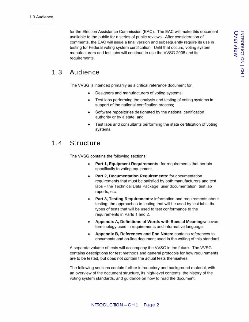
1.3 Audience
INTRODUCTION – CH 1 | Page 2
INTRO
DU
CTIO
N | C
H 1
Overview
for the Election Assistance Commission (EAC). The EAC will make this document available to the public for a series of public reviews. After consideration of comments, the EAC will issue a final version and subsequently require its use in testing for Federal voting system certification. Until that occurs, voting system manufacturers and test labs will continue to use the VVSG 2005 and its requirements.
1.3 Audience
The VVSG is intended primarily as a critical reference document for:
♦ Designers and manufacturers of voting systems;
♦ Test labs performing the analysis and testing of voting systems in support of the national certification process;
♦ Software repositories designated by the national certification authority or by a state; and
♦ Test labs and consultants performing the state certification of voting systems.
1.4 Structure
The VVSG contains the following sections:
♦ Part 1, Equipment Requirements: for requirements that pertain specifically to voting equipment.
♦ Part 2, Documentation Requirements: for documentation requirements that must be satisfied by both manufacturers and test labs – the Technical Data Package, user documentation, test lab reports, etc.
♦ Part 3, Testing Requirements: information and requirements about testing; the approaches to testing that will be used by test labs; the types of tests that will be used to test conformance to the requirements in Parts 1 and 2.
♦ Appendix A, Definitions of Words with Special Meanings: covers terminology used in requirements and informative language.
♦ Appendix B, References and End Notes: contains references to documents and on-line document used in the writing of this standard.
A separate volume of tests will accompany the VVSG in the future. The VVSG contains descriptions for test methods and general protocols for how requirements are to be tested, but does not contain the actual tests themselves.
The following sections contain further introductory and background material, with an overview of the document structure, its high-level contents, the history of the voting system standards, and guidance on how to read the document.
2.1 The New Structure of the VVSG
INTRODUCTION – CH 2 | Page 3
INTRO
DU
CTIO
N | C
H 2
Intro
ductio
n to
New
and E
xpan
ded
Material
Chapter 2: Introduction to New and Expanded Material
This document contains considerable new material and material expanded from previous versions of the voting standards. This section provides an introduction to and overview of major features of the VVSG, those being
♦ Organization of the VVSG, requirements structure, and classes;
♦ Usability performance metrics;
♦ Expanded human factors coverage;
♦ Software Independence, Independent Voter-Verifiable Records voting systems, and the Innovation Class;
♦ Open-ended vulnerability testing and expanded security coverage;
♦ Treatment of COTS in voting system testing;
♦ End-end testing for accuracy and reliability;
♦ New metric for voting system reliability; and
♦ Expanded core requirements coverage.
2.1 The New Structure of the VVSG
The VVSG structure is markedly different from the structure of previous versions. First, the VVSG should be considered as a foundation for requirements for voting systems; it is a foundation that provides precision, reduces ambiguity, eliminates repeated requirements, and provides an avenue for orderly change, i.e., the addition of new types of voting devices or voting variations.
It was necessary to focus on providing this robust foundation for several reasons. First, previous versions suffered from ambiguity, which resulted in a less-robust testing effort. In essence, it has been more difficult to test voting systems when the requirements themselves are subject to multiple interpretations. This new version should go a long way towards reducing that ambiguity.
Secondly, there are simply more different types of voting devices than anticipated by previous versions, and new devices will continue to be marketed as time goes by. The VVSG provides a strong organizational foundation so that existing devices can be unambiguously described and development of new devices can proceed in an orderly, structured fashion.
2.1 The New Structure of the VVSG
INTRODUCTION – CH 2 | Page 4
INTRO
DU
CTIO
N | C
H 2
Intro
ductio
n to
New
and E
xpan
ded
Material
2.1.1 VVSG Standards Architecture
The VVSG has been reorganized to bring it in line with applicable standards practices of ISO, W3C and other standards-creating organizations. It contains three volumes or “Parts” for different types of requirements:
Part 1, Equipment Requirements, provides guidelines for manufacturers to produce voting systems that are secure, accurate, reliable, usable, accessible, and fit for their intended use. Requirements in VVSG 2005 that were ambiguous have been clarified. In those cases where no precise replacement could be determined and no testing value could be ascribed, requirements have been deleted.
Part 2, Documentation Requirements, is a new section containing documentation requirements separate from functional and performance requirements applying to the voting equipment itself. It contains requirements applying to the Technical Data Package, the Voting Equipment User Documentation, the Test Plan, the Test Report, the Public Information Package, and the data for voting software repositories.
Part 3, Testing, contains requirements that apply to the national certification testing to be conducted by non-governmental certified testing laboratories. It has been reorganized to focus on test methods and to avoid repetition of requirements from the product standard. Although different testing specialties are likely to be subcontracted to different laboratories, the prime contractor must report to the certifying authority on the conformity of the system as a whole.
The requirements in these Parts rely on delimitation and strict usage of certain terms, included in Appendix A, Definition of Words with Special Meanings. This covers terminology for standardization purposes that must be sufficiently precise and formal to avoid ambiguity in the interpretation and testing of the standard. Terms are defined to mean exactly what is intended in the requirements of the standard. Note: Readers may already be familiar with definitions for many of the words in this section, but the definitions here often may differ in small or big ways from locality usage because they are used in special ways in the VVSG.
The VVSG also contains a table of requirement summaries, to be used as a quick reference for locating specific requirements within sections/subsections. Appendix B contains references and end notes.
2.1.2 Voting System and Device Classes
Voting system and device classes are new to the VVSG. Classes in essence form profiles of voting systems and devices. They are used as fields in requirements to connote the scope of the requirements. For example, Figure 2-1 shows the high-level device class called vote-capture device. There are various requirements that apply to vote-capture device; this means that all vote-capture devices must satisfy these requirements (e.g., for security, usability, etc.).

2.1 The New Structure of the VVSG
INTRODUCTION – CH 2 | Page 5
INTRO
DU
CTIO
N | C
H 2
Intro
ductio
n to
New
and E
xpan
ded
Material
There are also requirements that apply more specifically to, say, IVVR vote-capture devices and those explicit devices underneath it, such as VVPAT. These devices inherit the requirements that apply to vote-capture device, that is, they must satisfy all the general vote-capture device requirements as well as the more specific requirements that apply. In this way, new types of specific vote-capture devices can be added in the future; they must satisfy the general requirements that all Vote-capture devices are expected to satisfy, but at the same time they can satisfy specific requirements that only apply to the new device. This structure assists in unambiguously making it clear to manufacturers and test labs which requirements apply to ALL vote-capture devices, for example, as opposed to which requirements apply specifically to just VVPAT. This structure also allows for the addition or modification of new or existing device requirements without affecting the rest of the standard.
Figure 2-1 Voting device class hierarchy
2.1.3 Requirements Structure
Requirements are now very specific to either a type of voting variation or a type of voting device (as stated in the previous section, the voting device can be a general profile of certain types of voting devices or be a profile of a more specific voting device). The requirements contain expanded description text and more precise language to make requirements explicit and to indicate the general test method to be used by the test lab for determining whether the requirement is satisfied in the voting system under test. As appropriate, the requirement also contains a reference to versions of the requirement in previous standards (e.g., VVSG 2005 or the 2002 VSS) so as to show its genesis and to better convey its purpose.
IVVR vote-capture device
VVPAT
Vote-capture device
Requirements that every vote-capture device must meet (e.g., DRE, VVPAT, optical scanners, etc.)
Requirements that only IVVR vote-capture devices must meet (e.g., VVPAT, MMPB, EBM, etc.)
Requirements that only VVPAT devices must meet.
General, high-level
Less general, more device-specific
Device-specific

2.1 The New Structure of the VVSG
INTRODUCTION – CH 2 | Page 6
INTRO
DU
CTIO
N | C
H 2
Intro
ductio
n to
New
and E
xpan
ded
Material
2.1.4 Strict Terminology
The terminology used in the VVSG has been considered carefully and is used strictly and consistently. In this way, requirements language can be made even more clear and unambiguous. Hypertext links are used throughout the VVSG for definitions of terminology to reinforce the importance of understanding and using the terminology in the same way.
However, it is important to understand that the terminology used in the VVSG is specific to the VVSG. An effort has been made to make sure that the terms used in the VVSG mean essentially the same thing as used in other contexts, however at times the definitions in the VVSG may vary in big or small ways.
Figure 2-2 illustrates the relationships and interaction between requirements, device classes, and types of testing from Part 3, all in the framework of strictly used terminology.
Figure 2-2 Interaction between requirements, definitions, and parts of the VVSG
archival: (Media) Able to preserve content for a period of time without significant loss. Discussion: In the context of voting, the relevant period of time is usually 22 months. See Part 1 Section 6.5.3.
archivalness: Ability of a medium to preserve its content for a period of time without significant loss. Discussion: In the context of voting, the relevant period of time is usually 22 months. See Part 1 Section 6.5.3.
ATI: Audio-tactile interface.
audio VEBD: VEBD that communicates ballot information to the voter using sound.
audio-tactile interface: Electronic voter interface that does not require visual reading of a ballot. Discussion: Audio is used to convey information to the voter and sensitive tactile controls allow the voter to convey information to the voting system.
contest: (1) A single decision being put before the voters (e.g., the selection of candidates to fill a particular public office or the approval or disapproval of a constitutional amendment). Discussion: This term subsumes other terms such as "race," "question," and "issue" that are sometimes used to refer to specific kinds of contests. (2) Subdivision of a ballot pertaining to a single decision being put before the voters.
PART 2: DOCUMENTATION REQUIREMENTS
PART 1: EQUIPMENT REQUIREMENTS
The ATI SHALL allow the voter to skip to the next contest or return to previous contests.Applies to: Voting Device Class(es)Test Reference: Type(s) of Testing
PART 3: TESTING REQUIREMENTS
- Inspection- Functional
- Performance- Vulnerability- OEVT ...
Types of Testing
Voting Devices Classes
Definitions Specific to the VVSG
2.2 Usability Performance Requirements
INTRODUCTION – CH 2 | Page 7
INTRO
DU
CTIO
N | C
H 2
Intro
ductio
n to
New
and E
xpan
ded
Material
2.2 Usability Performance Requirements
Usability is conventionally defined as "the extent to which a product can be used by specified users to achieve specified goals with effectiveness, efficiency and satisfaction in a specified context of use" [ISO98a]. In VVSG 2005, the usability guidelines relied on three assessment methods:
1. Checking for the presence of certain design features which are believed to support usability, and for the absence of harmful design features;
2. Checking for the presence of certain functional capabilities which are believed to support usability; and
3. Requiring manufacturers to perform summative usability testing with certain classes of subjects and to report the results. However, the VVSG 2005 reporting requirements do not specify the details of how the test is designed and conducted.
While all these help to promote usability, methods 1 and 2 are all somewhat indirect methods. The actual "effectiveness, efficiency and satisfaction" of voting systems are never evaluated directly in the 3rd method.
This version of the VVSG uses a new method based on summative usability testing that directly addresses usability itself, i.e., measured mainly in how accurately voters cast their ballot choices. The features of this new method include:
♦ The definition of a standard testing protocol, including a test ballot, set of tasks to be performed, and demographic characteristics of the test participants. The protocol supports the test procedure as a repeatable controlled experiment.
♦ The use of a substantial number of human subjects attempting to perform those typical voting tasks on the systems being tested, in order to achieve statistically significant results.
♦ The gathering of detailed data on the subjects' task performance, including data on accuracy, speed, and confidence.
♦ The precise definition of the usability metrics to be derived from the experimental data.
♦ The definition of effectiveness benchmarks against which systems will be evaluated.
Obviously, the implementation of such complex tests is more difficult than simply checking design features. However, performance-based testing using human subjects yields the most meaningful measurement of usability because it is based on their interaction with the system's voter interface, whereas design guidelines, while useful, cannot be relied upon to discover all the potential problems that may arise. The inclusion of requirements for performance testing in these Guidelines advances the goal of providing the voter with a voting system that is accurate, efficient, and easy to use.

2.3 Expanded Usability and Accessibility Coverage
INTRODUCTION – CH 2 | Page 8
INTRO
DU
CTIO
N | C
H 2
Intro
ductio
n to
New
and E
xpan
ded
Material
2.3 Expanded Usability and Accessibility Coverage
In addition to usability performance metrics, the treatment of human factors, i.e., usability, accessibility, and privacy, has been expanded considerably. Table 2-1 summarizes the new and expanded material.
Table 2-1 Expanded human factors coverage
HUMAN FACTORS TOPIC DESCRIPTION
Voter-Editable Ballot Device
The VVSG defines a new class of voting station: Voter-Editable Ballot Device (VEBD). These are voting systems such as DREs and EBMs that present voters with an editable ballot (as opposed to manually-marked paper ballots), allowing them to easily change their choices prior to final casting of the ballot. See Part 1:2.5 and Part 1:3.1.2.
Ballot Checking and Correction
Requirements for both interactive and optical-scan based ballot checking and correction (so-called "voter's choice" issues). There is also a new requirement for detection and reporting of marginal marks. See Part 1:3.2.2.
Notification of Ballot Casting
Requirements to notify the voter whether the ballot has been cast successfully. See Requirements Part 1:3.2.2.1-F and Part 1:3.2.2.2-F.
Plain Language
Requirements for the use of plain language when the voting system communicates with the voter. The goal is to make the instructions for use of the system easier to understand and thus improve usability. See Requirement Part 1:3.2.4-C
Icons and Language New requirement that instructions cannot rely on icons alone; they must also include linguistic labels. See Requirement Part 1:3.2.4-G
Adjustability Clarified that when the voter can control or adjust some aspect of voting station, the adjustment can be done throughout the voting session. See Requirement Part 1:3.2.5-B
Choice of Font and Contrast
Requirements for the availability of the choice of font size and contrast on VEBDs. See Requirements Part 1:3.2.5-E and Part 1:3.2.5-H
Legibility Legibility for voters with poor reading vision has been strengthened from a recommendation to a requirement. See Requirements Part 1:3.2.5-G
Timing Requirements on the timing for interactive systems. Addresses the response time of system to the user (no undue delay) and mandates that systems issue a warning if there is lengthy user inactivity. See Section Part 1:3.2.6.1.
Alternative Languages This entire section has been expanded and clarified. See Section Part 1:3.2.7.
Poll Workers Addresses usability for poll workers as well as for voters. Manufacturers are required to perform usability testing of system setup, operation, and shutdown. System safety is addressed. See Section Part 1:3.2.8.
2.4 Software Independence
INTRODUCTION – CH 2 | Page 9
INTRO
DU
CTIO
N | C
H 2
Intro
ductio
n to
New
and E
xpan
ded
Material
End-to-End Accessibility
New requirement to ensure accessibility throughout the entire voting session. See Requirement Part 1:3.3.1-A
Accessibility of Paper Records
Requirements address the need for accessibility when the system uses paper records as the ballot or for verification. In particular, an audio readback mechanism is required to ensure accessibility for those with vision problems. See Requirement Part 1:3.3.1-E
Color Adjustment Consolidated and clarified material on color adjustment of voting station. See Requirement Part 1:3.3.2-B
Synchronized Audio and Video
Clarifies the availability of synchronized audio and video for the accessible voting station. The voter can choose any of three modes: audio-only, visual-only, or synchronized audio/video. See Requirement Part 1:3.3.2-D.
2.4 Software Independence
Software independence [Rivest06] means that an undetected error or fault in the voting system’s software is not capable of causing an undetectable change in election results. All voting systems must be software independent in order to conform to the VVSG.
There are essentially two issues behind the concept of software independence, one being that it must be possible to audit voting systems to verify that ballots are being recorded correctly, and the second being that testing software is so difficult that audits of voting system correctness cannot rely on the software itself being correct. Therefore, voting systems must be ‘software independent’ so that the audits do not have to trust that the voting system’s software is correct; the voting system must provide proof that the ballots have been recorded correctly, e.g., voting records must be produced in ways in which their accuracy does not rely on the correctness of the voting system’s software.
This is a major change from previous versions of the VVSG, because previous versions permitted voting systems that are software dependent, that is, voting systems whose audits must rely on the correctness of the software. One example of a software dependent voting system is the DRE, which is now non-conformant to this version of the VVSG.
2.4.1 Independent voter-verifiable records
The VVSG requires that, to be software independent, all voting systems include an IVVR vote-capture device, that is, a vote-capture device that uses independent voter-verifiable records (IVVR). IVVR can be audited independently of the voting system software but do not necessarily have to be paper-based. IVVR relies on voter-verification, that is, the voter must verify that the electronic record is being captured correctly by examining a copy that is maintained independently of the voting system’s software, i.e., the IVVR.

2.4 Software Independence
INTRODUCTION – CH 2 | Page 10
INTRO
DU
CTIO
N | C
H 2
Intro
ductio
n to
New
and E
xpan
ded
Material
Voter-verifiable paper records (VVPR) is a form of IVVR that is paper-based. Currently, the voting systems that can satisfy the definition of software independence use VVPR, such as with
♦ optical scanners used in conjunction with
♦ manually-marked paper ballots or
♦ an EBP or EBM; and
♦ VVPAT.
Figure 2-3 illustrates this in a tree-like structure. At the top of the tree is software independence; as stated previously all voting systems that are conformant to the VVSG must be software independent. One route to achieving software independence is to use IVVR. The VVSG contains requirements for IVVR, of which VVPR is one (currently the only) type. If different types of IVVR are developed that do not use paper, systems that use them can also be conformant to the VVSG “as is.” In other words, new types of IVVR that do not use paper are already “covered” by the IVVR requirements in the VVSG; new requirements will not necessarily need to be added.
Figure 2-3 Voting systems that can conform to current requirements in the VVSG
2.4.2 The Innovation Class
Use of IVVR is currently the only method specified by requirements in the VVSG for achieving software independence. Manufacturers that produce systems that do
Software Independence
Voting Systems Using
IVVR
Voting Systems Using
VVPR
Voting Systems Using New
Forms of IVVR
The Innovation Class
New Innovative Voting Systems - no requirements in VVSG - uses Innovation Class to determine conformance - ultimately could be added to VVSG’s requirements base
The VVSG
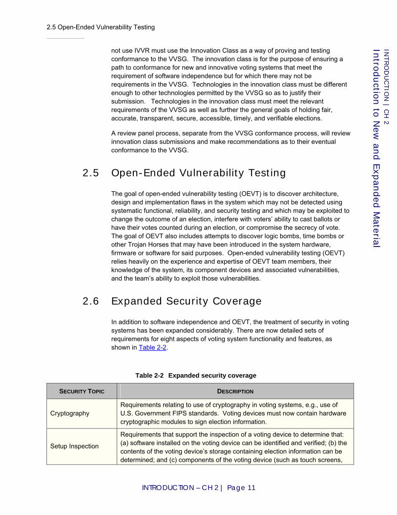
2.5 Open-Ended Vulnerability Testing
INTRODUCTION – CH 2 | Page 11
INTRO
DU
CTIO
N | C
H 2
Intro
ductio
n to
New
and E
xpan
ded
Material
not use IVVR must use the Innovation Class as a way of proving and testing conformance to the VVSG. The innovation class is for the purpose of ensuring a path to conformance for new and innovative voting systems that meet the requirement of software independence but for which there may not be requirements in the VVSG. Technologies in the innovation class must be different enough to other technologies permitted by the VVSG so as to justify their submission. Technologies in the innovation class must meet the relevant requirements of the VVSG as well as further the general goals of holding fair, accurate, transparent, secure, accessible, timely, and verifiable elections.
A review panel process, separate from the VVSG conformance process, will review innovation class submissions and make recommendations as to their eventual conformance to the VVSG.
2.5 Open-Ended Vulnerability Testing
The goal of open-ended vulnerability testing (OEVT) is to discover architecture, design and implementation flaws in the system which may not be detected using systematic functional, reliability, and security testing and which may be exploited to change the outcome of an election, interfere with voters’ ability to cast ballots or have their votes counted during an election, or compromise the secrecy of vote. The goal of OEVT also includes attempts to discover logic bombs, time bombs or other Trojan Horses that may have been introduced in the system hardware, firmware or software for said purposes. Open-ended vulnerability testing (OEVT) relies heavily on the experience and expertise of OEVT team members, their knowledge of the system, its component devices and associated vulnerabilities, and the team’s ability to exploit those vulnerabilities.
2.6 Expanded Security Coverage
In addition to software independence and OEVT, the treatment of security in voting systems has been expanded considerably. There are now detailed sets of requirements for eight aspects of voting system functionality and features, as shown in Table 2-2.
Table 2-2 Expanded security coverage
SECURITY TOPIC DESCRIPTION
Cryptography Requirements relating to use of cryptography in voting systems, e.g., use of U.S. Government FIPS standards. Voting devices must now contain hardware cryptographic modules to sign election information.
Setup Inspection
Requirements that support the inspection of a voting device to determine that: (a) software installed on the voting device can be identified and verified; (b) the contents of the voting device’s storage containing election information can be determined; and (c) components of the voting device (such as touch screens,
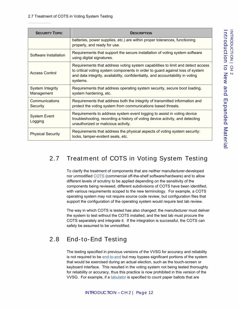
2.7 Treatment of COTS in Voting System Testing
INTRODUCTION – CH 2 | Page 12
INTRO
DU
CTIO
N | C
H 2
Intro
ductio
n to
New
and E
xpan
ded
Material
SECURITY TOPIC DESCRIPTION
batteries, power supplies, etc.) are within proper tolerances, functioning properly, and ready for use.
Software Installation Requirements that support the secure installation of voting system software using digital signatures.
Access Control
Requirements that address voting system capabilities to limit and detect access to critical voting system components in order to guard against loss of system and data integrity, availability, confidentiality, and accountability in voting systems.
System Integrity Management
Requirements that address operating system security, secure boot loading, system hardening, etc.
Communications Security
Requirements that address both the integrity of transmitted information and protect the voting system from communications based threats.
System Event Logging
Requirements to address system event logging to assist in voting device troubleshooting, recording a history of voting device activity, and detecting unauthorized or malicious activity.
Physical Security Requirements that address the physical aspects of voting system security: locks, tamper-evident seals, etc.
2.7 Treatment of COTS in Voting System Testing
To clarify the treatment of components that are neither manufacturer-developed nor unmodified COTS (commercial off-the-shelf software/hardware) and to allow different levels of scrutiny to be applied depending on the sensitivity of the components being reviewed, different subdivisions of COTS have been identified, with various requirements scoped to the new terminology. For example, a COTS operating system may not require source code review, but configuration files that support the configuration of the operating system would require test lab review.
The way in which COTS is tested has also changed; the manufacturer must deliver the system to test without the COTS installed, and the test lab must procure the COTS separately and integrate it. If the integration is successful, the COTS can safely be assumed to be unmodified.
2.8 End-to-End Testing
The testing specified in previous versions of the VVSG for accuracy and reliability is not required to be end-to-end but may bypass significant portions of the system that would be exercised during an actual election, such as the touch-screen or keyboard interface. This resulted in the voting system not being tested thoroughly for reliability or accuracy, thus this practice is now prohibited in this version of the VVSG. For example, if a tabulator is specified to count paper ballots that are
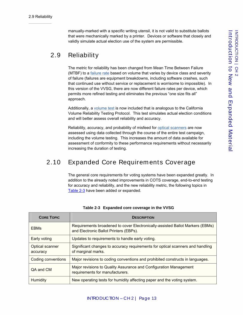
2.9 Reliability
INTRODUCTION – CH 2 | Page 13
INTRO
DU
CTIO
N | C
H 2
Intro
ductio
n to
New
and E
xpan
ded
Material
manually-marked with a specific writing utensil, it is not valid to substitute ballots that were mechanically marked by a printer. Devices or software that closely and validly simulate actual election use of the system are permissible.
2.9 Reliability
The metric for reliability has been changed from Mean Time Between Failure (MTBF) to a failure rate based on volume that varies by device class and severity of failure (failures are equipment breakdowns, including software crashes, such that continued use without service or replacement is worrisome to impossible). In this version of the VVSG, there are now different failure rates per device, which permits more refined testing and eliminates the previous “one size fits all” approach.
Additionally, a volume test is now included that is analogous to the California Volume Reliability Testing Protocol. This test simulates actual election conditions and will better assess overall reliability and accuracy.
Reliability, accuracy, and probability of misfeed for optical scanners are now assessed using data collected through the course of the entire test campaign, including the volume testing. This increases the amount of data available for assessment of conformity to these performance requirements without necessarily increasing the duration of testing.
2.10 Expanded Core Requirements Coverage
The general core requirements for voting systems have been expanded greatly. In addition to the already noted improvements in COTS coverage, end-to-end testing for accuracy and reliability, and the new reliability metric, the following topics in Table 2-3 have been added or expanded.
Table 2-3 Expanded core coverage in the VVSG
CORE TOPIC DESCRIPTION
EBMs Requirements broadened to cover Electronically-assisted Ballot Markers (EBMs) and Electronic Ballot Printers (EBPs).
Early voting Updates to requirements to handle early voting.
Optical scanner accuracy
Significant changes to accuracy requirements for optical scanners and handling of marginal marks.
Coding conventions Major revisions to coding conventions and prohibited constructs in languages.
QA and CM Major revisions to Quality Assurance and Configuration Management requirements for manufacturers.
Humidity New operating tests for humidity affecting paper and the voting system.

2.10 Expanded Core Requirements Coverage
INTRODUCTION – CH 2 | Page 14
INTRO
DU
CTIO
N | C
H 2
Intro
ductio
n to
New
and E
xpan
ded
Material
CORE TOPIC DESCRIPTION
Logic verification Requirements to show that the logic of the system satisfies certain constraints and correctness.
Epollbooks Requirements on ballot activation involving epollbooks to protect integrity and privacy of ballot activation information and to ensure records on epollbooks do not violate secrecy of the ballot.
Common data formats
Requirements dealing with making voting device interfaces and data formats transparent and interchangeable and to use consensus-based, publicly available formats.
3.1 Earlier NIST Involvement
INTRODUCTION – CH 3 | Page 15
INTRO
DU
CTIO
N | C
H 3
VVSG
Backg
round
Chapter 3: VVSG Background
This section contains background summary information on the VVSG, including the legislation responsible for its writing and a history of previous versions of the VVSG.
3.1 Earlier NIST Involvement
In 1974, the National Bureau of Standards (now the National Institute of Standards and Technology) began a research project under computer scientist Roy G. Saltman, funded by the Office of Federal Elections of the General Accounting Office. This project resulted in a 1975 NBS Interagency Report, later reprinted as SP 500-30, Effective Use of Computing Technology in Vote-Tallying [NIST75]. The report provided findings and conclusions about improving the accuracy and security of the vote-tallying process, about improving the management of the election preparation process, and about institutional factors affecting accuracy and security. The report also pointed out the lack of systematic research on election equipment and systems, and on human engineering of voting equipment, and it concluded that the setting of national minimum standards for federal election procedures would serve a valuable function.
3.2 The 1990 VSS
In 1984, Congress appropriated funds for the Federal Election Commission [FEC] to develop voluntary national standards for computer-based voting systems. The FEC formally approved the Performance and Test Standards for Punchcard, Marksense and Direct Recording Electronic Voting Systems in January 1990, which became known as the 1990 Voting Systems Standard, or 1990 VSS [GPO90].
The national testing effort was developed and overseen by the National Association of State Election Directors’ (NASED) Voting Systems Board, which is composed of election officials and independent technical advisors. NASED’s testing program was initiated in 1994 and more than 30 voting systems or components of voting systems have gone through the NASED testing and qualification process. In addition, many systems have subsequently been certified at the state level using the Standards in conjunction with functional and technical requirements developed by state and local policymakers to address the specific needs of their jurisdictions.

3.3 The 2002 VSS
INTRODUCTION – CH 3 | Page 16
INTRO
DU
CTIO
N | C
H 3
VVSG
Backg
round
3.3 The 2002 VSS
As the qualification process matured and qualified systems were used in the field, the Voting Systems Board, in consultation with the testing labs, identified certain testing issues that needed to be resolved. Moreover, rapid advancements in information and personal computer technologies introduced new voting system development and implementation scenarios not contemplated by the 1990 VSS.
In 1997, NASED briefed the FEC on the necessity for continued Commission involvement, citing the importance of keeping the Standards current in its reflection of modern and emerging technologies employed by voting system manufacturers. Following a Requirements Analysis released in 1999, the Commission authorized the Office of Election Administration to revise the Standards to reflect contemporary needs of the elections community. This resulted in the 2002 Voting System Standards, or 2002 VSS [VSS2002].
3.4 HAVA and VVSG 2005
In 2002, Congress passed the Help America Vote Act (HAVA) [HAVA02], which created a new process for improving voluntary voting system guidelines. A new federal entity was created, the Election Assistance Commission (EAC), to oversee the process. The EAC established the Technical Guidelines Development Committee (TGDC) in accordance with the requirements of Section 221 of HAVA pursuant to the Federal Advisory Committee Act, 5 U.S.C. App. 2. The objectives and duties were to act in the public interest to assist the EAC in the development of the voluntary voting system guidelines. The membership, as defined by HAVA, includes:
♦ The Director of the National Institute of Standards and Technology (NIST) who shall serve as its chair,
♦ Members of the EAC Standards Board,
♦ Members of the EAC Board of Advisors,
♦ Members of the Architectural and Transportation Barrier, and Compliance Board (U.S. Access Board),
♦ A representative of the American National Standards Institute (ANSI),
♦ A representative of the Institute of Electrical & Electronics Engineers (IEEE),
♦ Two representatives of the NASED selected by such Association who are not members of the Standards Board or Board of Advisors, and who are not of the same political party, and
♦ Other individuals with technical and scientific expertise relating to voting systems and voting equipment.
3.5 Relationship of HAVA and the VVSG
INTRODUCTION – CH 3 | Page 17
INTRO
DU
CTIO
N | C
H 3
VVSG
Backg
round
The TGDC first met in July 2004 and delivered its initial set of recommendations to the EAC in April 2005. Operating as a Federal Advisory Committee, the TGDC formed three working subcommittees:
♦ Security and Transparency (STS),
♦ Human Factors and Privacy (HFP), and
♦ Core Requirements and Testing (CRT).
The three subcommittees in collaboration with NIST recommended requirements for adoption by the full Committee at public plenary sessions. The TGDC’s initial set of recommendations, VVSG 2005, augmented the 2002 VSS by including security measures for auditability, wireless communications and software distribution and set up, and improvements for the accessibility guidelines and usability design guidelines for voting systems.
The TGDC also recommended that the VVSG 2005 be replaced with a far-reaching guideline that would address in-depth security, performance-based guidelines for usability testing and an overhaul of the standards and test methods to meet today’s more rigorous needs for electronic voting systems. This new VVSG applies to the next generation of voting equipment and addresses those needs.
3.5 Relationship of HAVA and the VVSG
Although both HAVA and the VVSG contain requirements, the scope and application are quite different in the two cases. HAVA is a Federal law that, among other things, provides to the states financial aid for the purchase of new voting equipment. In section 301 it also sets forth broad functional standards for voting systems as used in Federal elections. That is, it governs the systems as actually deployed in polling places throughout the country. Violation of these standards may result in adverse action by the Department of Justice against a State or other voting jurisdiction. The standards encompass procedures as well as equipment, e.g. the requirement that each state adopt a uniform definition of a "vote".
The VVSG is a set of highly detailed technical requirements in support of the broad goals of HAVA. These requirements apply only to voting equipment, not to procedures in the polling place. If a type of voting system (i.e. a particular make and model) meets all of the VVSG requirements (as determined by conformance testing conducted by an accredited laboratory), then that type is eligible to be certified as being compliant with the VVSG. Thus the VVSG is addressed to manufacturers of voting equipment, not to states. Finally, although many states will purchase only equipment that has been certified, the guidelines are voluntary in that states are free to purchase and use non-certified systems, as long as they comply with the HAVA standards.
Table 3-1 HAVA and the VVSG
CHARACTERISTIC HAVA VVSG
Status Federal Law Federal Guidelines

3.5 Relationship of HAVA and the VVSG
INTRODUCTION – CH 3 | Page 18
INTRO
DU
CTIO
N | C
H 3
VVSG
Backg
round
CHARACTERISTIC HAVA VVSG
Scope Voting Systems and Procedures Voting Equipment
Primary Audience States Equipment Manufacturers
Enforcement Dept of Justice EAC
Phase of Life-cycle Procurement/Deployment Conformance Testing
Level of Specification Broad/Functional Detailed/Technical

4.1 Requirements Language and Structure
INTRODUCTION – CH 4 | Page 19
INTRO
DU
CTIO
N | C
H 4
Usin
g T
his D
ocu
men
t
Chapter 4: Using This Document
As noted, this document is intended primarily for voting system manufacturers and test lab personnel. However, the language used throughout has been improved and made more understandable for most audiences. This section contains a brief overview of how to read the document and best understand its features and requirements.
4.1 Requirements Language and Structure
The first place to start in understanding the VVSG is to understand how language is used. The language is divided into two categories: normative, i.e., the requirements language itself, and informative. Informative parts of this document include discussion, examples, extended explanations, and other matter that is necessary for proper understanding of the requirements and conformance to them. Informative text may serve to clarify requirements, but it is not otherwise applicable.
Normative language is specifically for requirements. The following keywords are used within requirements text to indicate the conformance aspects of the requirement:
♦ SHALL indicates a mandatory requirement to do something;
♦ IS PROHIBITED indicates a mandatory requirement not to do something;
♦ SHOULD, IS ENCOURAGED indicate an optional recommended action;
♦ MAY indicates an optional, permissible action.
The requirements are structured specifically to make them clear and precise. Requirements may have subrequirements, usually used when the main requirement needs further definition of its implications. A typical requirement and subrequirement (taken from Part 1:3.3.3) are as follows:
3.3.3-C Audio Features and characteristics
Voting stations that provide audio presentation of the ballot SHALL do so in a usable way, as detailed in the following subrequirements.
Applies to: VEBD-A
Test Reference: Part 3:3.2 “Functional Testing”
D I S C U S S I O N
These requirements apply to all voting system audio output, not just to the ATI of an accessible voting station.
4.2 The Conformance Clause and Classes
INTRODUCTION – CH 4 | Page 20
INTRO
DU
CTIO
N | C
H 4
Usin
g T
his D
ocu
men
t
3.3.3-C.1 Standard connector
The ATI SHALL provide its audio signal through an industry standard connector for private listening using a 3.5mm stereo headphone jack to allow voters to use their own audio assistive devices.
Applies to: VEBD-A
Test Reference: Part 3 Section 3.2
Requirements and their subrequirements are designated by the “ ” and “ ” characters, respectively. Requirements are numbered according to the section of the VVSG they appear in; the titles serve as a shorthand description. The actual text of a requirement appears directly below the requirement in blue. Requirements have the following fields:
♦ Applies to: indicates which voting system or device class the requirement applies to (see the discussion of classes in the following section);
♦ Test Reference: what type of testing must be used for testing whether the requirement is met; these point to appropriate sections in Part 3: Testing Requirements;
♦ DISCUSSION: optional: informative supporting information for the requirement;
♦ Reference: optional: the source for the requirement; many requirements are new.
Each usage of a word or term with special meaning in the VVSG, such as voting stations, ATI, or accessible voting station, is linked to its definition in Appendix A: Definitions of Words with Special Meanings.
4.2 The Conformance Clause and Classes
With some background on requirements structure and language, readers may wish to read Part 1:Chapter 2: Conformance Clause for the discussion on classes and to interpret requirements language. The purpose of classes is to categorize requirements into related groups of functionality that apply to different types of voting systems and devices. Understanding how classes work is the key for understanding requirements and their implications.
The conformance clause chapter is highly technical in nature, thus the following is a summary of its discussion on classes:
There are two types of classes:
1. Voting system classes: each class pertains to a voting system that supports a specific voting variation, e.g., primary elections, open primaries, straight party voting, etc.

4.2 The Conformance Clause and Classes
INTRODUCTION – CH 4 | Page 21
INTRO
DU
CTIO
N | C
H 4
Usin
g T
his D
ocu
men
t
2. Voting device classes: each class pertains to a voting device, ranging from higher-level classes such as vote-capture device to lower-level, specific classes that describe specific devices such as VVPAT or PCOS.
Most requirements have an Applies to: field that contains the name of a class or several classes that the requirement essentially applies to, e.g., a requirement dealing with cryptography with Applies to: Vote-capture device, means that all vote-capture devices must satisfy the requirement. The vast majority of requirements in the VVSG apply to device classes, i.e., types of voting devices.
4.2.1 Inheritance in device classes
As stated previously, classes may subsume (or incorporate) other subclasses below them in the hierarchy. For example, vote-capture device subsumes IVVR vote-capture device, which subsumes other subclasses beneath it. The subsuming class is called the superclass, while the subsumed classes are called subclasses.
Figure 4-1 Class inheritance
Subclasses inherit the requirements of their superclasses, e.g., in the class diagram in Figure 4-1, the lines that connect the classes show that EPB inherits all requirements that apply to EBM, which inherits all requirements that apply to IVVR vote-capture device, which inherits all requirements that apply to vote-capture device. A subclass may add new requirements, e.g., IVVR vote-capture device contains requirements in addition to those that apply to vote-capture device and so forth. However, a subclass is not allowed to relax or remove requirements inherited from a superclass; everything that applies to vote-capture device, for example, applies also to every subclass of vote-capture device.
EBP
Vote-capture device
EBMMMPB
IVVR vote-capture device
VVPAT
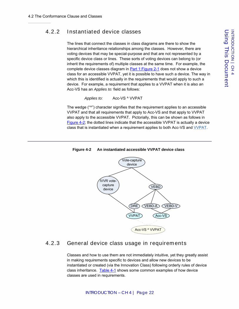
4.2 The Conformance Clause and Classes
INTRODUCTION – CH 4 | Page 22
INTRO
DU
CTIO
N | C
H 4
Usin
g T
his D
ocu
men
t
4.2.2 Instantiated device classes
The lines that connect the classes in class diagrams are there to show the hierarchical inheritance relationships among the classes. However, there are voting devices that may be special-purpose and that are not represented by a specific device class or lines. These sorts of voting devices can belong to (or inherit the requirements of) multiple classes at the same time. For example, the complete device classes diagram in Part 1:Figure 2-1 does not show a device class for an accessible VVPAT, yet it is possible to have such a device. The way in which this is identified is actually in the requirements that would apply to such a device. For example, a requirement that applies to a VVPAT when it is also an Acc-VS has an Applies to: field as follows:
Applies to: Acc-VS ^ VVPAT
The wedge (“^”) character signifies that the requirement applies to an accessible VVPAT and that all requirements that apply to Acc-VS and that apply to VVPAT also apply to the accessible VVPAT. Pictorially, this can be shown as follows in Figure 4-2; the dotted lines indicate that the accessible VVPAT is actually a device class that is instantiated when a requirement applies to both Acc-VS and VVPAT.
Figure 4-2 An instantiated accessible VVPAT device class
4.2.3 General device class usage in requirements
Classes and how to use them are not immediately intuitive, yet they greatly assist in making requirements specific to devices and allow new devices to be instantiated or created (via the Innovation Class) following orderly rules of device class inheritance. Table 4-1 shows some common examples of how device classes are used in requirements.
Vote-capture device
VEBD
IVVR vote-capture device
VVPAT
DRE
Acc-VS
VEBD-A VEBD-V
Acc-VS ^ VVPAT
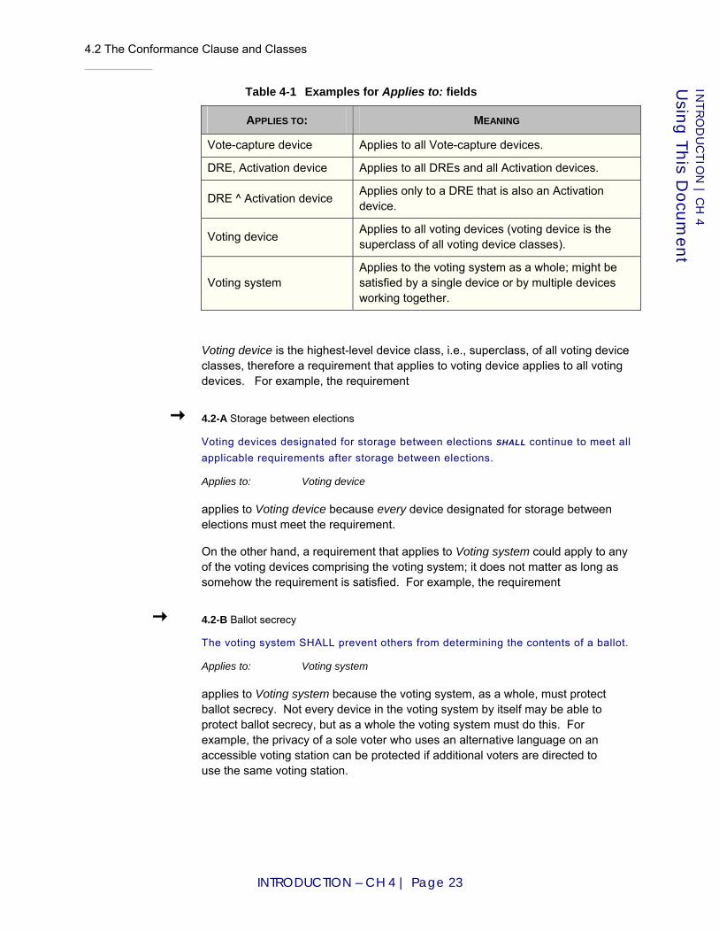
4.2 The Conformance Clause and Classes
INTRODUCTION – CH 4 | Page 23
INTRO
DU
CTIO
N | C
H 4
Usin
g T
his D
ocu
men
t
Table 4-1 Examples for Applies to: fields
APPLIES TO: MEANING
Vote-capture device Applies to all Vote-capture devices.
DRE, Activation device Applies to all DREs and all Activation devices.
DRE ^ Activation device Applies only to a DRE that is also an Activation device.
Voting device Applies to all voting devices (voting device is the superclass of all voting device classes).
Voting system Applies to the voting system as a whole; might be satisfied by a single device or by multiple devices working together.
Voting device is the highest-level device class, i.e., superclass, of all voting device classes, therefore a requirement that applies to voting device applies to all voting devices. For example, the requirement
4.2-A Storage between elections
Voting devices designated for storage between elections SHALL continue to meet all applicable requirements after storage between elections.
Applies to: Voting device
applies to Voting device because every device designated for storage between elections must meet the requirement.
On the other hand, a requirement that applies to Voting system could apply to any of the voting devices comprising the voting system; it does not matter as long as somehow the requirement is satisfied. For example, the requirement
4.2-B Ballot secrecy
The voting system SHALL prevent others from determining the contents of a ballot.
Applies to: Voting system
applies to Voting system because the voting system, as a whole, must protect ballot secrecy. Not every device in the voting system by itself may be able to protect ballot secrecy, but as a whole the voting system must do this. For example, the privacy of a sole voter who uses an alternative language on an accessible voting station can be protected if additional voters are directed to use the same voting station.

4.3 Navigating Through Requirements
INTRODUCTION – CH 4 | Page 24
INTRO
DU
CTIO
N | C
H 4
Usin
g T
his D
ocu
men
t
4.3 Navigating Through Requirements
There is a requirement listing provided immediately after the table of contents in this document. Readers can navigate through the document using this list and quickly identify requirements in various sections.
As noted previously, requirements that use words with special meanings are linked to their definitions in Appendix A. References in requirements and informative text are linked to Appendix B.
Part 1: Equipment Requirements, contains requirements applying to the voting system and the voting devices that it contains. It is intended primarily for use by manufacturers and testing labs. It may also be of use to election officials in setting requirements for voting systems in requests for proposals. It contains 8 chapters, organized as follows:
♦ Chapter 1: Introduction;
♦ Chapter 2: Conformance-related information and requirements;
♦ Chapter 3: Usability, accessibility, and privacy requirements;
♦ Chapter 4: Auditing and records-related requirements;
♦ Chapter 5: Security-related requirements;
♦ Chapters 6-7: Core requirements and requirements arranged by voting activity; and
♦ Chapter 8: Reference models – process model, vote-capture device state model, and logic model.
Part 2: Documentation Requirements, contains requirements applying to the Technical Data Package, the Voting Equipment User Documentation, the Test Plan, the Test Report, the Public Information Package, and the data for repositories. It is intended primarily for use by manufacturers, test labs, and software repositories. It contains 7 chapters, organized as follows:
♦ Chapter 1: Introduction;
♦ Chapter 2: Manufacturer requirements for quality assurance and configuration management documentation provided to test labs;
♦ Chapter 3: Manufacturer requirements for documentation to be included in the technical data package provided to test labs;
♦ Chapter 4: Manufacturer requirements for documentation provided to users, i.e., customers;
♦ Chapter 5: Requirements for the voting system test plan by the test lab;
♦ Chapter 6: Requirements for the test report by the test lab; and
♦ Chapter 7: Requirements for test results-related documentation to be made available to the public.
Lastly, Part 3: Testing Requirements contains requirements applying to the conformity assessment to be conducted by test labs. It is intended primarily for
4.3 Navigating Through Requirements
INTRODUCTION – CH 4 | Page 25
INTRO
DU
CTIO
N | C
H 4
Usin
g T
his D
ocu
men
t
use by test labs. Requirements in Part 1 and Part 2 reference sections in Part 3 to indicate the general methods for how the requirements are to be tested (but not the tests themselves). Part 3 contains 5 chapters, organized as follows:
♦ Chapter 1: Introduction;
♦ Chapter 2: Overview of the conformity assessment process and related requirements;
♦ Chapter 3: Overview of general testing approaches;
♦ Chapter 4: Requirements for documentation and design reviews; and
♦ Chapter 5: Requirements for different methods for testing.

4.3 Navigating Through Requirements
INTRODUCTION – CH 4 | Page 26
INTRO
DU
CTIO
N | C
H 4
Usin
g T
his D
ocu
men
t

VVSG Recommenda t i ons
t o t he EAC
P A R T 1 :
Equipment Requirements
Prepared at the Direction of the
Technical Guidelines Development Committee
August 2007

PART 1 – CH 1 | Page 1
Part 1: Equipment Requirements
Chapter 1: Introduction
This part of the VVSG, Equipment Requirements, contains requirements applying to the voting system and the voting devices that it contains. It is intended primarily for use by manufacturers and testing labs. The Equipment Requirements may also be of use to election officials in setting requirements for voting systems in requests for proposals.
This part contains 8 chapters, organized as follows:
♦ Chapter 2: conformance-related information and requirements;
♦ Chapter 3: usability, accessibility, and privacy requirements;
♦ Chapter 4: auditing and records-related requirements;
♦ Chapter 5: security-related requirements;
♦ Chapter 6: core requirements;
♦ Chapter 7: requirements arranged by voting activity; and
♦ Chapter 8: reference models – process model, vote-capture device state model, and logic model.
1.1 Changes from VVSG 2005 and Previous Versions of the Standards
1.1.1 Conformance clause
The conformance clause has been expanded to define classes of voting systems and devices. Classes are an evolution of the notion of voting system "categories" that appeared in previous Guidelines. Those categories were paper-based, DRE, precinct count and central count.
The conformance clause also contains requirements for software independence, and the two methods for satisfying software independence in the VVSG:
♦ Use of independent voter-verified records (IVVR);
♦ The Innovation Class.
IVVR is a general category; voter-verified paper records (VVPR) is the only type of IVVR used by voting systems. In essence, only voting systems that use VVPR can currently conform to the VVSG unless new types of IVVR are developed.

1.1 Changes from VVSG 2005 and Previous Versions of the Standards
PART 1 – CH 1 | Page 2
PART 1: E
QU
IPM
EN
T R
EQ
UIR
EM
EN
TS | C
H 1
Intro
ductio
n
The Innovation Class is a method for specifying new and innovative voting systems that meet the definition of software independence but in other ways besides IVVR.
1.1.2 Usability Performance Benchmarks
The usability requirements in VVSG 2005 contained requirements that are design-based. This version of the VVSG retains some of those requirements but also uses a new method based on summative usability testing that may more directly addresses the usability of the voting system, based on how accurately test participants are able to vote. The features of this new method include:
♦ The definition of a standard testing protocol, including a test ballot, set of tasks to be performed, and demographic characteristics of the test participants. The protocol supports the test procedure as a repeatable controlled experiment;
♦ The use of a substantial number of human subjects attempting to perform those typical voting tasks on the systems being tested, in order to achieve statistically significant results;
♦ The gathering of detailed data on the subjects' task performance, including data on accuracy, speed, and confidence;
♦ The precise definition of the usability metrics to be derived from the experimental data;
♦ The definition of effectiveness benchmarks against which systems will be evaluated.
1.1.3 Security requirements
The security requirements for voting systems have been expanded from VVSG 2005 to provide more complete coverage for different types of voting devices and for all phases of voting. Three entirely new sections have been added for voting device cryptography, event logging, and system integrity management. A number of other sections of security material from VVSG 2005 have been reworked and expanded.
VVSG 2005 contained a section on independent verification systems and VVPAT. This material has been largely reworked to focus on requirements on voting system records for voting systems that use independent voter-verifiable records (IVVR), including VVPAT and optical scan (which use one form of IVVR, voter-verifiable paper records (VVPR)). The concept of independent verification has been broadened to software independence.
The new section on voting device cryptography specifies that signatures for protecting electronic voting records used in audits be generated in an embedded hardware signature module, and includes a basic key management scheme. The new section on event logging expands logging requirements for voting devices and using secure log techniques.
1.1 Changes from VVSG 2005 and Previous Versions of the Standards
PART 1 – CH 1 | Page 3
PART 1: E
QU
IPM
EN
T R
EQ
UIR
EM
EN
TS | C
H 1
Intro
ductio
n
The new section on system integrity management deals with operating system and application software security all system modes of voting. Some of the requirements are based on controls specified on technical standards for gaming machines [NGC06]. The requirements mandate secure boot loading and digital signature verification on binaries before loading. There are additional requirements on backups and expanded requirements from VVSG 2005 dealing with malware detection.
The access control section of VVSG 2005 now specifies baseline access controls for voting system resources such as data files, application programs, underlying operating systems, and voting system devices. The section specifies minimum types of authentication for role-based and identity-based access control.
The telecommunications and wireless communication sections of VVSG 2005 have been combined. A major difference is that this version of the VVSG prohibits radio frequency wireless in voting systems; VVSG 2005 restricted but did not prohibit radio frequency wireless.
The setup validation requirements in VVSG 2005 have been reworked into a newer section on software inspection. A major change in this section is that voting systems are no longer required to be capable of supporting a software setup validation technique that operates independently of the voting system. VVSG 2005 I.7.4.6 required this to be performed via a read-only external interface or by other means; this requirement has been removed in favor of requirements to support software independence and that verify digital signatures on binaries prior to loading.
1.1.4 Epollbooks and ballot activation
Requirements on ballot activation involving epollbooks have been added to Part 1:7.5.1 “Issuance of voting credentials and ballot activation”. New requirements have been added primarily to protect integrity and privacy of ballot activation credential information and to ensure records on epollbooks and vote-capture devices cannot be aggregated to violate secrecy of the ballot. Epollbooks are permitted to activate the ballot while connected to an external voter registration database; various requirements on network security are included.
1.1.5 Common data format
Requirements dealing with making voting device interfaces and data formats transparent and interchangeable have been added to Part 1:6.6 “Integratability and Data Export/Interchange”. Although these requirements do not mandate a specific standard data format, manufacturers are encouraged to use consensus-based, publicly available formats such as the OASIS Election Markup Language (EML) standard [OASIS07] or those emanating from the IEEE Voting System Electronic Data Interchange Project 1622 [P1622].
1.1 Changes from VVSG 2005 and Previous Versions of the Standards
PART 1 – CH 1 | Page 4
PART 1: E
QU
IPM
EN
T R
EQ
UIR
EM
EN
TS | C
H 1
Intro
ductio
n
1.1.6 Core requirements
The core requirements for voting systems to define elections and to collect, count, and report votes have been expanded to specify what functionality must be provided in order to claim support for the many jurisdiction-specific voting variations such as cumulative voting, straight party voting, etc. In previous versions of the guidelines, manufacturers were required to identify which variations were supported and to document how those variations were supported, but the guidelines lacked any functional requirements on the variations. The new requirements define a baseline of functionality for each of the voting variations.
The requirements have been broadened to cover Electronically-assisted Ballot Markers (EBMs) and Electronic Ballot Printers (EBPs). These devices' combination of a DRE-like interface with a paper-based method of recording votes was something that previous versions of the guidelines did not handle.
The metric for reliability has been changed from Mean Time Between Failure (MTBF) to a failure rate based on volume that varies by device class and severity of failure. The metric for accuracy has been changed from ballot position error rate to report total error rate, and separate requirements referring to specific, low-level operations have been replaced with a single, general, end-to-end accuracy requirement. The metrics for multiple feed and rejection of ballots that meet all manufacturer specifications have been merged into a single "misfeed" metric. In each case, revised benchmarks have been derived from input from the Technical Guidelines Development Committee and election officials.
Significant changes have been made to the accuracy requirements for optical scanners. Previous versions of the guidelines required optical scanners to conform to a low error rate requirement when reading marks that were made to manufacturer specifications. This requirement has been retained, but is now supplemented by a requirement to read a standard mark made with a #2 pencil with the same level of accuracy. A related requirement to ignore "extraneous perforations, smudges and folds," which under some interpretations is unattainable with existing technology, has been adjusted to recognize that there is no mechanical way of determining whether a given mark that appears within a voting target is extraneous or not. This ties into the well-known problem of voter intent. Marks appearing outside of voting targets, on the other hand, are always extraneous—at least as far as standard behavior is concerned. Systems that support detection of circled voting targets and other marks that jurisdictions may consider to be valid votes must also support a baseline, standard mode of operation in which such marks are ignored.
Requirements and discussion on the handling of marginal marks have been added. See Part 1:7.7.5.1 “Marginal marks”.
Requirements on the content of vote data reports, which appeared in several places and in different ways in previous versions of the guidelines, have been unified, harmonized, and clarified. Required contexts for reporting have been specified, and the concepts cast ballot, read ballot and counted ballot have been
1.1 Changes from VVSG 2005 and Previous Versions of the Standards
PART 1 – CH 1 | Page 5
PART 1: E
QU
IPM
EN
T R
EQ
UIR
EM
EN
TS | C
H 1
Intro
ductio
n
clearly distinguished. The quantities to be included in vote data reports have been formally defined using a logic model.
Other changes include
♦ Made compatible with early voting.
♦ Clarified that the redundant records stored by DREs are for recoverability purposes, and not to be confused with independent voter-verifiable records as specified in Part 1:4.4 ”Independent Voter-Verifiable Records”.
♦ Clarified and generalized the prohibition on counter overflow.
♦ Specified that voting systems should flag any discrepancies in vote data reports that are detectable by the system.
♦ Added "should" requirements for reporting the count of blank ballots and for combined precinct reporting.
♦ Separated election administration concerns from product requirements.
♦ Replaced the term ballot format, which was inherited from [GPO90], with the term used in modern practice, ballot style.
1.1.7 Coding conventions
Volume 1, Section 5.2 and Volume 2, Section 5.4 of [VVSG2005] define coding conventions and a source code review to be conducted by test labs. That material has been substantially revised in these Guidelines.
[VVSG2005] Volume 1, Section 5.2.6 specifies that manufacturers be permitted to use current best practices in lieu of the coding conventions defined in the VVSG. However, the coding conventions in [VVSG2005] are not aligned with the modern state of the practice, and if followed, could do more harm than good. The misalignments are (1) that the conventions, some of which were carried over from [GPO90], are out of date, and (2) that the conventions, being limited by the requirement to remain language-neutral, are variously incomplete and/or inappropriate in the context of different programming languages with their different idioms and practices. The vast majority of coding conventions used in practice are tailored to specific programming languages.
In these Guidelines, the few coding conventions that have significant impact on integrity and transparency and that generalize relatively well to different programming languages have been retained, expanded, and made mandatory, while the many coding conventions that are language-sensitive and stylistic in nature, and are made redundant by more recent, publicly available coding conventions, have been removed in favor of the published conventions. Meanwhile, the evaluation of logical correctness that was underspecified in [VVSG2005] has been greatly enhanced (see Part 1:6.4.1 “Software engineering practices”).

1.1 Changes from VVSG 2005 and Previous Versions of the Standards
PART 1 – CH 1 | Page 6
PART 1: E
QU
IPM
EN
T R
EQ
UIR
EM
EN
TS | C
H 1
Intro
ductio
n
Prominent among the requirements addressing logical transparency is the requirement to use high-level control constructs and to refrain from using the low-level arbitrary branch (a.k.a. goto). As is reflected in Part 1:Table 6-4, most high-level concepts for control flow were established by the time the first edition of the guidelines was published and are supported by all of the programming languages that were examined as probable candidates for voting system use as of this iteration. However, two additional concepts have been slower to gain universal support.
1.1.8 Applicability to COTS and borderline COTS products
To clarify the treatment of components that are neither manufacturer-developed nor unmodified COTS and to allow different levels of scrutiny to be applied depending on the sensitivity of the components being reviewed, new terminology has been introduced: application logic, border logic, configuration data, core logic, COTS (revised definition), hardwired logic, and third-party logic. Using this terminology, requirements have been scoped more precisely than they were in previous iterations of the Guidelines.
The new terminology obviates the software vs. firmware distinction that in practice has sometimes caused confusion. The requirements applying to application logic are not relaxed in any way if that logic is realized in firmware or hardwired logic instead of software. Consequently, the use of hardwired logic in an application logic capacity is all but prohibited, as it is unlikely to meet requirements such as Requirement Part 1:6.4.1.2-A. It is expected that hardwired logic will be limited to COTS and border logic.
By requiring "many different applications," the definition of COTS deliberately prevents any application logic from receiving a COTS designation.
Details regarding the testing implications of these revisions are provided in Part 3:1.1.2 “Applicability to COTS and borderline COTS products”.
1.1.9 Reference models
Part 1:8.1 “Process Model (informative)” provides an informative model of the entire voting process.
Part 1:8.2 “Vote-Capture Device State Model (informative)” provides an informative state model for vote-capture devices to clarify the definitions of voting session and active period, particularly for the case of early voting.
Part 1:8.3 “Logic Model (normative)” provides normative terms and constraints for use in evaluating the correctness of voting system logic. Part 3:4.6 “Logic Verification” describes the verification procedure.
1.1 Changes from VVSG 2005 and Previous Versions of the Standards
PART 1 – CH 1 | Page 7
PART 1: E
QU
IPM
EN
T R
EQ
UIR
EM
EN
TS | C
H 1
Intro
ductio
n
1.1.10 Deletions
Requirements regarding the system's handling of unofficial data and reports have been deleted or converted to procedural requirements because the distinction between unofficial and official data is often outside the scope of the voting system. It is now assumed that any vote data present on a voting system and any reports that it generates are potentially official. Requirements on the reconciliation of provisional ballots and other activities involved in the creation of official data are unaffected by this change.
As discussed, prescriptive coding conventions not directly related to integrity and transparency have been deleted in favor of published, credible conventions.
Requirements on system and device availability have been deleted because they did not reflect the logistical overhead of repairing equipment on election day and because it is generally impossible to place precinct equipment back into service after it has been repaired on election day without raising concerns about possible tampering. Instead, Requirement Part 1:6.3.1 “Reliability” has been tightened to discourage equipment from failing in the first place.
A requirement to designate one set of redundant electronic CVRs in a DRE as the "primary" set has been deleted because it prejudices the result of an audit.
Requirements that were redundant with the definitions of device classes (e.g., [VSS2002] I.2.4.3.2.1.b, all paper-based systems shall allow the voter to punch or mark the ballot to register a vote) have been deleted.
Requirements predicated on state law, local practices, software developed by the voting jurisdiction, and other variables that are indeterminate and untestable in the federal certification process have been deleted.
Requirements that were stated in terms of vague generalities, such as "appropriate" or "intended" options or behavior, for which no precise replacement could be determined and to which no testing value could be ascribed, have been deleted.
Vacuous requirements, such as "Be of any size and shape consistent with its intended use," have been deleted.
Redundant requirements, such as "Comply with the requirements of Section Y" when Section Y is already known to be applicable, have been deleted.
Informative text that was overtaken by changes in the requirements or the structure of the Guidelines has been deleted.
Definitions and requirements pertaining to punchcard technology have been deleted.

1.1 Changes from VVSG 2005 and Previous Versions of the Standards
PART 1 – CH 1 | Page 8
PART 1: E
QU
IPM
EN
T R
EQ
UIR
EM
EN
TS | C
H 1
Intro
ductio
n
1.1.11 Supplemental Guidance
Throughout Part 1 are informative subsections titled "Procedures required for correct system functioning." The requirements in these subsections provide context for what the functional requirements specify or, more often, for what they omit. These requirements do not pertain to the voting system and are not tested by an accredited test lab.

2.1 Structure of Requirements
PART 1 – CH 2 | Page 9
PART 1: E
QU
IPM
EN
T R
EQ
UIR
EM
EN
TS | C
H 2
Confo
rman
ce Clau
se
Chapter 2: Conformance Clause
This chapter provides information and requirements relating to how manufacturers and test labs can use the features of this document to assess whether a voting system conforms to the VVSG. It is written with these audiences in mind; the overview information in Chapter 4 of the Introduction is written for readers with less-technical backgrounds.
2.1 Structure of Requirements
Each part of the VVSG is organized into hierarchically organized sections that address topics of interest. Sections typically begin with prose explaining the general purpose, etc. This is informative background to help understand the requirements. Sections also contain requirements, which are the hard and fast rules to be followed for conformance. The VVSG carefully distinguish normative requirements from informative context using conventions that are explained below.
Each voting system requirement is identified according to a hierarchical scheme in which higher-level, "parent" requirements (such as "provide accessibility for visually impaired voters") are supported by lower-level subrequirements (e.g., "provide an audio-tactile interface"). "Parent" requirements have identifiers consisting of a section number suffixed by a letter (e.g., 1.2.3-A) and are indicated by straight arrows in the left margin. Subrequirements have identifiers consisting of their parent requirements' identifiers suffixed by a digit (e.g., 1.2.3-A.1) and are indicated by bent arrows in the left margin.
Each requirement is composed of a descriptive title, normative text, optional informative discussion, and two fields labeled Applies to: and Test reference:.
The applicability of a requirement is specified with the Applies to: field, which indicates the class(es) of voting systems or devices to which the requirement applies. Classes are defined in Part 1:2.6 “Extensions”.
A requirement having N different classes separated by commas in its Applies to: field is equivalent to N separate requirements that repeat the same text, each repetition applying to one of the listed classes.
The scope of a parent requirement is inherited by its subrequirements unless they explicitly specify a narrower scope. The scope may be narrowed through a generic relation (e.g., DRE is a subclass of Vote-capture device) or a partitive relation (e.g., a DRE is part of a Voting system). If no narrowing is needed then the Applies to: field may be omitted.
The Test reference: field indicates the general testing approach or approaches that would be used to assess conformity with the requirement.

2.2 Normative Language
PART 1 – CH 2 | Page 10
PART 1: E
QU
IPM
EN
T R
EQ
UIR
EM
EN
TS | C
H 2
Confo
rman
ce Clau
se
2.2 Normative Language
The following keywords are used to convey conformance requirements:
♦ SHALL indicates a mandatory requirement to do something. Synonymous with "is required to."
♦ IS PROHIBITED indicates a mandatory requirement not to do something. Synonymous with "shall not."
♦ SHOULD, IS ENCOURAGED indicate an optional recommended action, one that is particularly suitable, without mentioning or excluding others. Synonymous with "is permitted and recommended."
♦ MAY indicates an optional, permissible action. Synonymous with "is permitted."
Requirements are further indicated by the presence of blue text and arrows in the left margin. Requirements are directly applicable to achieving conformance to the VVSG.
Informative parts of this document include discussion, examples, extended explanations, and other matter that is necessary for proper understanding of the VVSG and conformance to them. Informative text may serve to clarify requirements, but it is not otherwise applicable to achieving conformance to the VVSG.
2.3 Conformance Designations
A voting system conforms to the product standard if all stated requirements that apply to the voting system and its constituent devices are fulfilled. The implementation statement (see Part 1:2.4 “Implementation Statement”) declares the capabilities, features and optional functions that have been implemented and are subject to conformity assessment.
There is no concept of partial conformance—neither that a voting system is x % conforming, nor that a device that is not a complete voting system by itself is conforming. Individual devices of voting systems are not tested except as parts of complete systems. [3]
2.4 Implementation Statement
An implementation statement documents the requirements that have been implemented by the voting system, the optional features and capabilities supported by the voting system, and any extensions (i.e., additional functionality beyond what is defined in the VVSG) that it implements.
An implementation statement may take the form of a checklist to be completed for each voting system submitted for conformity assessment. It is used by test labs to identify the conformity assessment activities that are applicable.

2.5 Classes
PART 1 – CH 2 | Page 11
PART 1: E
QU
IPM
EN
T R
EQ
UIR
EM
EN
TS | C
H 2
Confo
rman
ce Clau
se
2.4-A Implementation statement
An implementation statement SHALL include: a. Full product identification of the voting system, including version
number or timestamp; b. Separate identification of each device (see below) that is part of the
voting system; c. Version of VVSG to which conformity assessment is desired; d. Classes implemented (see Part 1:2.5.3 “Classes identified in
implementation statement”); e. Device capacities and limits (especially those appearing in Part
1:8.3.1 “Domain of discourse”); f. List of languages supported; and g. Signed attestation that the foregoing accurately characterizes the
system submitted for testing. Test Reference: Part 3:4.1 “Initial Review of Documentation”
D I S C U S S I O N
This requirement addresses many issues about the scope of conformity assessment and uncertainty whether particular features have been implemented in voting systems.
A keyboard, mouse or printer connected to a programmed voting device, as well as any optical drive, hard drive or similar component installed within it, are considered components of the voting device, not separate devices. The voting device is "responsible" for these components—e.g., a DRE must prevent unauthorized flashing of the firmware in its optical drive or other components that could be subverted to manipulate vote outcomes.
Specified capacities and limits should include the limit (if any) on the length of a candidate name that the system can process and display without truncation and similar limits for any other text fields whose usable or practically usable sizes are bounded. If the system provides a way to access the entirety of a long name even when it does not fit the width of the display and does not use any data structures that would force truncation, such a limit might not apply.
Manufacturers may wish to contact their intended testing labs in advance to determine if those labs can supply them with an implementation statement pro forma to facilitate meeting this requirement.
Source: New requirement.
2.5 Classes
2.5.1 Voting device terminology
The following terms are defined in Appendix A: voting device, activation device, vote-capture device, IVVR vote-capture device, paper-based device, electronic device, programmed device, tabulator, precinct tabulator, central tabulator, audit

2.5 Classes
PART 1 – CH 2 | Page 12
PART 1: E
QU
IPM
EN
T R
EQ
UIR
EM
EN
TS | C
H 2
Confo
rman
ce Clau
se
device, VEBD, Acc-VS, MMPB, EBM, VEBD-A, VEBD-V, DRE, VVPAT, optical scanner, ECOS, MCOS, PCOS, CCOS, and EMS.
2.5.2 Classes overview
A class simultaneously identifies a set of requirements and a set of voting systems or devices to which those requirements apply. The purpose of classes is to categorize requirements into related groups of functionality that apply to different types of voting systems and devices.
Classes may subsume other classes. For example, Paper-based device subsumes MMPB, EBM, and Optical scanner. The subsuming class is called the superclass while the subsumed classes are called subclasses.
A group of related classes forms a classification lattice with a largest class at the top and a smallest class at the bottom. The largest class subsumes all other classes. For voting systems the largest class is called Voting system; for voting devices the largest class is called Voting device. The smallest class is subsumed by all other classes. In this discussion the smallest classes are unnamed and are only present to complete the formalism.
Subclasses "inherit" the requirements of their superclasses. Additionally, a subclass may further constrain a class by adding new requirements. However, a subclass is not allowed to relax or remove requirements inherited from a superclass.
There is no assumption of disjointness for classes. Unless otherwise specified, a voting system or device may belong to several classes simultaneously, such as Acc-VS and DRE to signify an accessible DRE device.
A voting system conforms to a class if all stated requirements identified by that class are fulfilled. Since subclasses are not allowed to relax or remove requirements inherited from a superclass, it is true in all cases that a voting system or device conforming to a subclass also conforms to all of its superclasses. For example, a voting system conforming to any subclass of Voting system fulfills the general requirements that apply to all voting systems.
The classification mechanism is useful in many different contexts when there is a need to identify specific portions of the VVSG. Part 1:Table 2-1 provides several examples.
Table 2-1 Use of classes in different contexts
CONTEXT USE
VVSG Requirements applicable to a given class
Implementation statement This system conforms to a specified class
Conformity assessment Tests and reviews applicable to the specified class
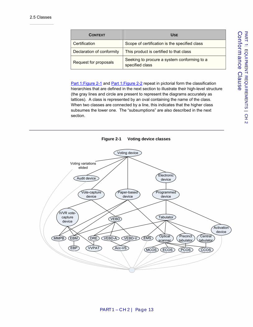
2.5 Classes
PART 1 – CH 2 | Page 13
PART 1: E
QU
IPM
EN
T R
EQ
UIR
EM
EN
TS | C
H 2
Confo
rman
ce Clau
se
CONTEXT USE
Certification Scope of certification is the specified class
Declaration of conformity This product is certified to that class
Request for proposals Seeking to procure a system conforming to a specified class
Part 1:Figure 2-1 and Part 1:Figure 2-2 repeat in pictorial form the classification hierarchies that are defined in the next section to illustrate their high-level structure (the gray lines and circle are present to represent the diagrams accurately as lattices). A class is represented by an oval containing the name of the class. When two classes are connected by a line, this indicates that the higher class subsumes the lower one. The “subsumptions” are also described in the next section.
Figure 2-1 Voting device classes
Voting device
Voting variations elided
EBP
Vote-capture device
Tabulator
Paper-based device
EMS Optical scanner
Central tabulator
Precinct tabulatorEBMMMPB
VEBD
PCOSMCOS ECOS
Audit device
Activation device
CCOS
Electronic device
Programmed device
IVVR vote-capture device
VVPAT
DRE
Acc-VS
VEBD-A VEBD-V
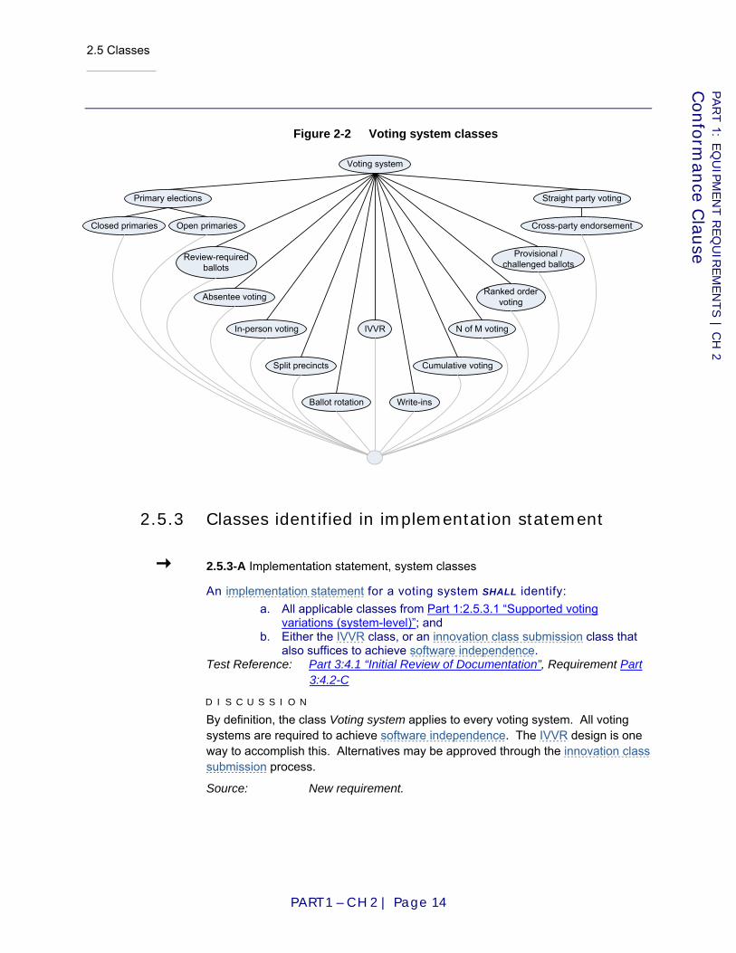
2.5 Classes
PART 1 – CH 2 | Page 14
PART 1: E
QU
IPM
EN
T R
EQ
UIR
EM
EN
TS | C
H 2
Confo
rman
ce Clau
se
Figure 2-2 Voting system classes
2.5.3 Classes identified in implementation statement
2.5.3-A Implementation statement, system classes
An implementation statement for a voting system SHALL identify: a. All applicable classes from Part 1:2.5.3.1 “Supported voting
variations (system-level)”; and b. Either the IVVR class, or an innovation class submission class that
also suffices to achieve software independence. Test Reference: Part 3:4.1 “Initial Review of Documentation”, Requirement Part
3:4.2-C
D I S C U S S I O N
By definition, the class Voting system applies to every voting system. All voting systems are required to achieve software independence. The IVVR design is one way to accomplish this. Alternatives may be approved through the innovation class submission process.
Source: New requirement.
Voting system
Review-requiredballots
N of M voting
Provisional /challenged ballots
Absentee voting
In-person voting
Ballot rotation
Cumulative votingSplit precincts
Write-ins
Ranked order voting
Cross-party endorsement
Straight party votingPrimary elections
Closed primaries Open primaries
IVVR
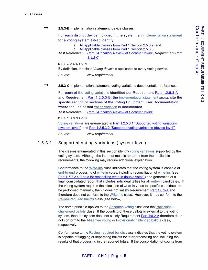
2.5 Classes
PART 1 – CH 2 | Page 15
PART 1: E
QU
IPM
EN
T R
EQ
UIR
EM
EN
TS | C
H 2
Confo
rman
ce Clau
se
2.5.3-B Implementation statement, device classes
For each distinct device included in the system, an implementation statement for a voting system SHALL identify:
a. All applicable classes from Part 1 Section 2.5.3.2; and b. All applicable classes from Part 1 Section 2.5.3.3.
Test Reference: Part 3:4.1 “Initial Review of Documentation”, Requirement Part 3:4.2-C
D I S C U S S I O N
By definition, the class Voting device is applicable to every voting device.
Source: New requirement.
2.5.3-C Implementation statement, voting variations documentation references
For each of the voting variations identified per Requirement Part 1:2.5.3-A and Requirement Part 1:2.5.3-B, the implementation statement SHALL cite the specific section or sections of the Voting Equipment User Documentation where the use of that voting variation is documented. Test Reference: Part 3:4.1 “Initial Review of Documentation”
D I S C U S S I O N
Voting variations are enumerated in Part 1:2.5.3.1 “Supported voting variations (system-level)” and Part 1:2.5.3.2 “Supported voting variations (device-level)”.
Source: New requirement.
2.5.3.1 Supported voting variations (system-level)
The classes enumerated in this section identify voting variations supported by the voting system. Although the intent of most is apparent from the applicable requirements, the following may require additional explanation.
Conformance to the Write-ins class indicates that the voting system is capable of end-to-end processing of write-in votes, including reconciliation of write-ins (see Part 1:7.7.2.4 “Logic for reconciling write-in double votes”) and generation of a final, consolidated report that includes individual tallies for all write-in candidates. If the voting system requires the allocation of write-in votes to specific candidates to be performed manually, then it does not satisfy Requirement Part 1:6.2-A and therefore does not conform to the Write-ins class. However, it may conform to the Review-required ballots class (see below).
The same principle applies to the Absentee voting class and the Provisional-challenged ballots class. If the counting of these ballots is external to the voting system, then the system does not satisfy Requirement Part 1:6.2-A therefore does not conform to the Absentee voting or Provisional-challenged ballots class, respectively.
Conformance to the Review-required ballots class indicates that the voting system is capable of flagging or separating ballots for later processing and including the results of that processing in the reported totals. If the consolidation of counts from
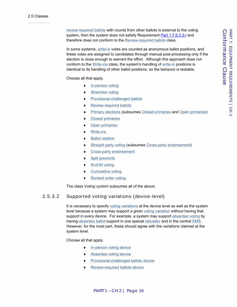
2.5 Classes
PART 1 – CH 2 | Page 16
PART 1: E
QU
IPM
EN
T R
EQ
UIR
EM
EN
TS | C
H 2
Confo
rman
ce Clau
se
review-required ballots with counts from other ballots is external to the voting system, then the system does not satisfy Requirement Part 1:7.8.3.3-I and therefore does not conform to the Review-required ballots class.
In some systems, write-in votes are counted as anonymous ballot positions, and these votes are assigned to candidates through manual post-processing only if the election is close enough to warrant the effort. Although this approach does not conform to the Write-ins class, the system's handling of write-in positions is identical to its handling of other ballot positions, so the behavior is testable.
Choose all that apply.
♦ In-person voting
♦ Absentee voting
♦ Provisional-challenged ballots
♦ Review-required ballots
♦ Primary elections (subsumes Closed primaries and Open primaries)
♦ Closed primaries
♦ Open primaries
♦ Write-ins
♦ Ballot rotation
♦ Straight party voting (subsumes Cross-party endorsement)
♦ Cross-party endorsement
♦ Split precincts
♦ N-of-M voting
♦ Cumulative voting
♦ Ranked order voting
The class Voting system subsumes all of the above.
2.5.3.2 Supported voting variations (device-level)
It is necessary to specify voting variations at the device level as well as the system level because a system may support a given voting variation without having that support in every device. For example, a system may support absentee voting by having absentee ballot support in one special tabulator and in the central EMS. However, for the most part, these should agree with the variations claimed at the system level.
Choose all that apply.
♦ In-person voting device
♦ Absentee voting device
♦ Provisional-challenged ballots device
♦ Review-required ballots device
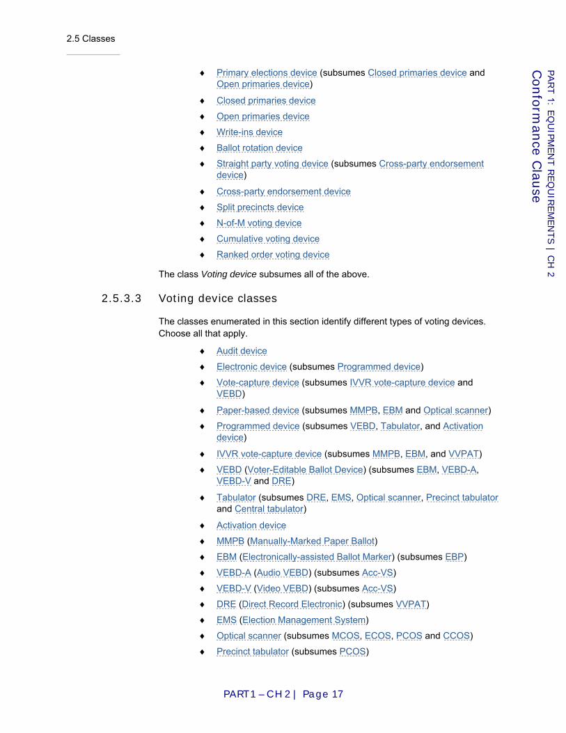
2.5 Classes
PART 1 – CH 2 | Page 17
PART 1: E
QU
IPM
EN
T R
EQ
UIR
EM
EN
TS | C
H 2
Confo
rman
ce Clau
se
♦ Primary elections device (subsumes Closed primaries device and Open primaries device)
♦ Closed primaries device
♦ Open primaries device
♦ Write-ins device
♦ Ballot rotation device
♦ Straight party voting device (subsumes Cross-party endorsement device)
♦ Cross-party endorsement device
♦ Split precincts device
♦ N-of-M voting device
♦ Cumulative voting device
♦ Ranked order voting device
The class Voting device subsumes all of the above.
2.5.3.3 Voting device classes
The classes enumerated in this section identify different types of voting devices. Choose all that apply.
♦ Audit device
♦ Electronic device (subsumes Programmed device)
♦ Vote-capture device (subsumes IVVR vote-capture device and VEBD)
♦ Paper-based device (subsumes MMPB, EBM and Optical scanner)
♦ Programmed device (subsumes VEBD, Tabulator, and Activation device)
♦ IVVR vote-capture device (subsumes MMPB, EBM, and VVPAT)
♦ VEBD (Voter-Editable Ballot Device) (subsumes EBM, VEBD-A, VEBD-V and DRE)
♦ Tabulator (subsumes DRE, EMS, Optical scanner, Precinct tabulator and Central tabulator)
♦ Activation device
♦ MMPB (Manually-Marked Paper Ballot)
♦ EBM (Electronically-assisted Ballot Marker) (subsumes EBP)
♦ VEBD-A (Audio VEBD) (subsumes Acc-VS)
♦ VEBD-V (Video VEBD) (subsumes Acc-VS)
♦ DRE (Direct Record Electronic) (subsumes VVPAT)
♦ EMS (Election Management System)
♦ Optical scanner (subsumes MCOS, ECOS, PCOS and CCOS)
♦ Precinct tabulator (subsumes PCOS)
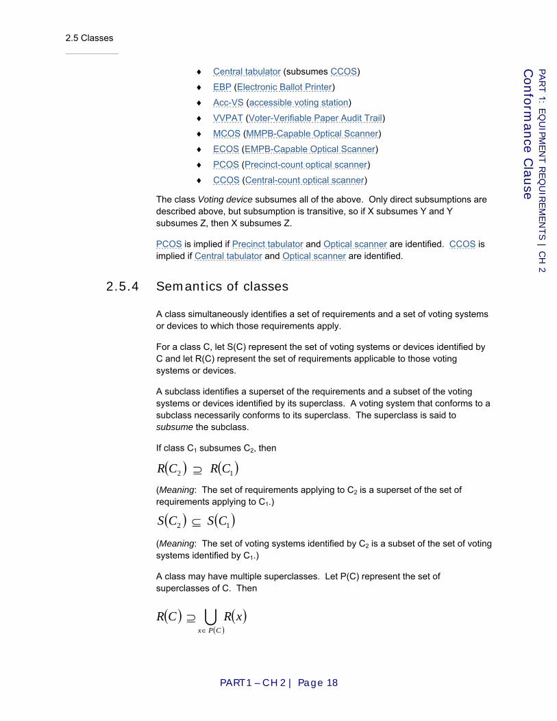
2.5 Classes
PART 1 – CH 2 | Page 18
PART 1: E
QU
IPM
EN
T R
EQ
UIR
EM
EN
TS | C
H 2
Confo
rman
ce Clau
se
♦ Central tabulator (subsumes CCOS)
♦ EBP (Electronic Ballot Printer)
♦ Acc-VS (accessible voting station)
♦ VVPAT (Voter-Verifiable Paper Audit Trail)
♦ MCOS (MMPB-Capable Optical Scanner)
♦ ECOS (EMPB-Capable Optical Scanner)
♦ PCOS (Precinct-count optical scanner)
♦ CCOS (Central-count optical scanner)
The class Voting device subsumes all of the above. Only direct subsumptions are described above, but subsumption is transitive, so if X subsumes Y and Y subsumes Z, then X subsumes Z.
PCOS is implied if Precinct tabulator and Optical scanner are identified. CCOS is implied if Central tabulator and Optical scanner are identified.
2.5.4 Semantics of classes
A class simultaneously identifies a set of requirements and a set of voting systems or devices to which those requirements apply.
For a class C, let S(C) represent the set of voting systems or devices identified by C and let R(C) represent the set of requirements applicable to those voting systems or devices.
A subclass identifies a superset of the requirements and a subset of the voting systems or devices identified by its superclass. A voting system that conforms to a subclass necessarily conforms to its superclass. The superclass is said to subsume the subclass.
If class C1 subsumes C2, then
(Meaning: The set of requirements applying to C2 is a superset of the set of requirements applying to C1.)
(Meaning: The set of voting systems identified by C2 is a subset of the set of voting systems identified by C1.)
A class may have multiple superclasses. Let P(C) represent the set of superclasses of C. Then
( ) ( )12 CSCS ⊆
( ) ( )12 CRCR ⊇
( )( )
( )xRCRCPx
U∈
⊇

2.5 Classes
PART 1 – CH 2 | Page 19
PART 1: E
QU
IPM
EN
T R
EQ
UIR
EM
EN
TS | C
H 2
Confo
rman
ce Clau
se
(Meaning: The set of requirements applying to C is a superset of the union of the sets of requirements applying to each of C's superclasses.)
(Meaning: The set of voting systems identified by C is a subset of the intersection of the sets of voting systems identified by each of C's superclasses.)
Given classes C3 and C4, one may derive a new subclass by combining C3 and C4. The combining operation on classes is represented with a wedge (⋀).
By default, this new subclass, C3 ⋀ C4, identifies the union of the requirements and the intersection of the voting systems or devices identified by C3 and C4. However, additional requirements that applied to neither superclass may apply specifically to the new subclass.
(Meaning: The set of requirements applying to C3 ⋀ C4 is a superset of the union of the set of requirements applying to C3 and the set of requirements applying to C4.)
(Meaning: The set of voting systems identified by C3 ⋀ C4 is the intersection of the set of voting systems identified by C3 and the set of voting systems identified by C4.)
Part 1:Figure 2-3 shows an example in which a new subclass is derived from Acc-VS and VVPAT.
Figure 2-3 Device class formed by wedge (⋀)
A class that is derived by combining classes that are disjoint is said to be incoherent and identifies no voting systems or devices. The set of requirements identified by an incoherent class is likely to be self-contradictory.
VVPATAcc-VS
DRE
VEBD
VEBD-A VEBD-V
Acc-VS ^ VVPAT
( ) ( )( )I
CPx
xSCS∈
⊆
( ) ( ) ( )4343 CRCRCCR U⊇∧
( ) ( ) ( )4343 CSCSCCS I=∧

2.6 Extensions
PART 1 – CH 2 | Page 20
PART 1: E
QU
IPM
EN
T R
EQ
UIR
EM
EN
TS | C
H 2
Confo
rman
ce Clau
se
2.6 Extensions
Extensions are additional functions, features, and/or capabilities included in a voting system that are not defined in the VVSG. To accommodate the needs of states that may impose additional requirements and to accommodate changes in technology, these VVSG allow extensions. However, as extensions are essentially subclasses of one or more classes defined in these VVSG, they are subject to the integrity constraint that applies to all subclasses: an extension is not allowed to contradict or relax requirements that would otherwise apply to the system and its constituent devices.
2.6-A Extensions shall not break conformance
Extensions SHALL NOT contradict or relax requirements of these VVSG.
2.7 Software Independence
This section contains requirements related to software independence. Software independence means that an undetected error or fault in the voting system’s software is not capable of causing an undetectable change in election results. All voting systems must be software independent in order to conform to the VVSG. There are currently two methods specified in the VVSG for achieving software independence: 1) through the use of independent voter-verifiable records (IVVR) and 2) through the innovation class.
2.7-A Software independence
Voting systems SHALL be software independent, that is, an undetected error or fault in the voting system’s software SHALL NOT be capable of causing an undetectable change in election results.
Applies to: Voting system
Test Reference: Part 3:4.1 “Initial Review of Documentation”, Requirement Part 3:4.2-C
D I S C U S S I O N
The requirement applies to the voting system class, meaning that all voting systems that conform to the VVSG must be software independent.
Source: New requirement
2.7.1 Achieving software independence via independent voter-verifiable records
Voting systems that use independent voter-verifiable records can satisfy the software independence requirement and thus achieve conformance to the VVSG. Such systems include systems that use voter-verifiable paper records (VVPR),

2.7 Software Independence
PART 1 – CH 2 | Page 21
PART 1: E
QU
IPM
EN
T R
EQ
UIR
EM
EN
TS | C
H 2
Confo
rman
ce Clau
se
such as (a) VVPAT and (b) optical scan used in conjunction with manually-marked paper ballots or with paper ballots that are electronically marked by an EBP or EBM.
2.7.1-A IVVR, software independence
Software independence MAY be achieved through the use of independent voter-verifiable records or it MAY be achieved through an innovation class submission.
Applies to: IVVR
Test Reference: Part 3:4.1 “Initial Review of Documentation”, Requirement Part 3:4.2-C
D I S C U S S I O N
This requirement is implied by Requirement Part 1:2.5.3-A, which requires the implementation statement to include an IVVR voting system or an innovation class submission. Use of IVVR is the only method specified by requirements in the VVSG for achieving software independence. The usage of MAY instead of SHALL indicates that the Requirement Part 1:2.7-A may also be satisfied in other ways through submissions to the innovation class.
Source: New requirement
2.7.1-B IVVR, requires IVVR vote-capture device
In a voting system of the IVVR class, every vote-capture device SHALL be an IVVR vote-capture device.
Applies to: IVVR
Test Reference: Part 3:4.1 “Initial Review of Documentation”, Requirement Part 3:4.2-C
D I S C U S S I O N
Voting systems that satisfy the IVVR voting system class requirements must include an IVVR vote-capture device, e.g., VVPAT, EBM, or MMPB. Conversely, voting systems of the IVVR class must not include any vote-capture devices that are not of the IVVR vote-capture device class.
Source: New requirement
2.7.2 Innovation class submissions
The innovation class is for the purpose of ensuring a path to conformance for new and innovative voting systems that meet the requirement of software independence but for which there may not be requirements in the VVSG.
The following high-level principles apply to the innovation class:
♦ Technologies in the innovation class must sufficiently different from other technologies permitted by the VVSG so as to justify their submission. In particular, it should be clear in submissions that the
2.7 Software Independence
PART 1 – CH 2 | Page 22
PART 1: E
QU
IPM
EN
T R
EQ
UIR
EM
EN
TS | C
H 2
Confo
rman
ce Clau
se
“standard” path towards achieving conformance to the VVSG is not appropriate for the proposed technology;
♦ A reasonable case must be made that deployment of the new technology does not present excessive logistical complexities. In particular, if the proposed technology is based on multiple interacting components (e.g., cryptographic key certification authorities, public electronic bulletin boards, smart witness devices, multiple holders of shared keys, etc.), then deployment of these components, interoperability testing, and control and maintenance of the various communication paths should not present insurmountable problems.
♦ A reasonable case must be made that the new technology does not present an excessive burden on election administration. More generally, the technology should help rather than hinder election administrators in their goal of producing timely, accurate, and trustable election results.
♦ Technologies in the innovation class must meet the relevant requirements of the VVSG as well as further the general goals of holding fair, accurate, transparent, secure, accessible, timely, and verifiable elections. They must be as secure, transparent, and auditable as existing systems permitted by the VVSG.
A review panel process, separate from the VVSG conformance process, will review innovation class submissions and make recommendations as to eventual conformance to the VVSG.
In terms of conformance to the VVSG class structure, an innovation class submission is a voting system that includes one or more distinct innovative devices. The manufacturer must follow the same procedures that any manufacturer of a voting system must follow except that the manufacturer must also request and justify that a new device class be created in the VVSG for each distinct innovative device in the submission. For each new device class requested, the manufacturer must show where in the device class structure the new class is to be created. In listing the specific requirements of the new class, the manufacturer is expected to follow all rules of class hierarchy and requirement inheritance from Section 2.6.
2.7.2-A Innovation class, submission procedures
For each distinct innovation class submission, the manufacturer SHALL adhere to the same submission procedures and requirements as for standard submissions.
Applies to: Voting system
Test Reference: Part 3:4.1 “Initial Review of Documentation”
Source: New requirement
2.7 Software Independence
PART 1 – CH 2 | Page 23
PART 1: E
QU
IPM
EN
T R
EQ
UIR
EM
EN
TS | C
H 2
Confo
rman
ce Clau
se
2.7.2-B Innovation class, identification of innovativeness
Each distinct innovation class submission SHALL include additional documentation that provides an explanation as to why the voting system and its accompanying devices are innovative and how they differ from voting technology that implements other voting device classes in the VVSG.
Applies to: Voting system
Test Reference: Part 3:4.1 “Initial Review of Documentation”
D I S C U S S I O N
The submission in effect requests the creation of a new device class for each distinct innovative device included in the voting system. This requirement is for the purpose of evaluating whether the creation of a new class is justified. To satisfy this requirement, the submitter may provide an overview of the device describing its functionality, boundaries, and interactions with other devices.
Source: New requirement
2.7.2-C Innovation class, new device class
For each distinct innovation class submission, the manufacturer SHALL request and justify that a new device class be created in the VVSG for each distinct innovative device in the submission
Applies to: Voting system
Test Reference: Part 3:4.1 “Initial Review of Documentation”, Requirement Part 3:4.2-C
Source: New requirement
2.7.2-C.1 Innovative class, device class submission
For each distinct innovation device class submission included In the voting system, the implementation statement for the voting system SHALL identify the new device classes to be created and where they fit into the device class hierarchy.
Applies to: Voting system
Test Reference: Part 3:4.1 “Initial Review of Documentation”, Requirement Part 3:4.2-C
Source: New requirement
2.7.2-C.2 Innovation class, device class identification of requirements
For each distinct innovation device class submission included in the voting system, the implementation statement for the voting system SHALL identify all requirements that apply to the new class and suggested test methods.
Applies to: Voting system

2.7 Software Independence
PART 1 – CH 2 | Page 24
PART 1: E
QU
IPM
EN
T R
EQ
UIR
EM
EN
TS | C
H 2
Confo
rman
ce Clau
se
Test Reference: Part 3:4.1 “Initial Review of Documentation”, Requirement Part 3:4.2-C
D I S C U S S I O N
Identification of applicable requirements may occur through inheritance from superclasses or it may occur through reuse of requirements from other, similar classes.
Source: New requirement

3.1 Overview
PART 1 – CH 3 | Page 25
PART 1: E
QU
IPM
EN
T R
EQ
UIR
EM
EN
TS | C
H 3
Usab
ility, Accessib
ility, and Privacy R
equirem
ents
Chapter 3: Usability, Accessibility, and Privacy Requirements
3.1 Overview
The importance of usability and accessibility in the design of voting systems has become increasingly apparent. It is not sufficient that the internal operation of these systems be correct; in addition, voters and election officials must be able to use them effectively and efficiently.
There are some properties of voting systems that make good design especially difficult:
♦ The voting task itself can be fairly complex; the voter may have to navigate an electronic ballot, choose multiple candidates in a single contest, understand the effect of party-line voting, or decide on ballot questions written in legal language;
♦ Voting is performed infrequently (compared with tasks such as using an ATM), so there is relatively limited opportunity for voters and poll workers to gain familiarity with the process;
♦ Changes in the election process, including new voting equipment, may require voters and poll workers to use new and unfamiliar procedures; and
♦ The set of "users" for voting equipment is exceptionally diverse. The voting public encompasses a broad range of factors, including physical and cognitive abilities, language skills, and technology experience.
3.1.1 Purpose
The challenge, then, is to provide a voting system that voters can use comfortably, efficiently, and with justified confidence that they have cast their votes correctly. The requirements within this section are intended to serve that goal. Three broad principles motivate this section:
1. All eligible voters are to have access to the voting process without discrimination. The voting process must be accessible to individuals with disabilities. The voting process includes access to the polling place, instructions on how to vote, initiating the voting session, selecting among contest choices, review of the ballot, final submission of the ballot, and getting help when needed.
2. Each cast ballot must accurately capture the selections made by the voter. The ballot must be presented to the voter in a manner that is

3.1 Overview
PART 1 – CH 3 | Page 26
PART 1: E
QU
IPM
EN
T R
EQ
UIR
EM
EN
TS | C
H 3
Usab
ility, Accessib
ility, and Privacy R
equirem
ents
clear and usable. Voters should encounter no difficulty or confusion regarding the process for recording their votes.
3. The voting process must preserve the secrecy of the ballot. The voting process should preclude anyone else from determining the content of a voter's ballot, without the voter's cooperation. If such a determination is made against the wishes of the voter, then his or her privacy has been violated.
Note that these principles refer to the entire voting process. The VVSG applies only to voting systems; other aspects of the process (such as administrative rules and procedures) are outside the scope of the VVSG, but are nonetheless crucial for the full achievement of the principles.
3.1.2 Special terminology
Several uncommon terms are used in this section. For the convenience of the reader, they are defined below. Many other technical terms frequently used throughout the VVSG are defined in Appendix A. Note in particular the distinctions among these terms: voting process, voting system, voting device, voting session, and voting station.
♦ Accessible Voting Station (Acc-VS) - the voting station specially equipped for individuals with disabilities referred to in HAVA 301 (a)(3)(B).
♦ Audio-Tactile Interface (ATI) - a voter interface designed not to require visual reading of a ballot. Audio is used to convey information to the voter and sensitive tactile controls allow the voter to convey information to the voting system.
♦ Common Industry Format (CIF) - the format to be used for summative usability test reporting, described in ISO/IEC 25062:2006 "Common Industry Format (CIF) for Usability Test Reports" [ISO06e].
♦ Summative Usability Testing - evaluation of a product with representative users and tasks designed to measure the usability (defined as effectiveness, efficiency and satisfaction) of the complete product. The purpose of a summative test is to evaluate a product through defined measures, rather than diagnosis and correction of specific design problems, as in formative testing.
♦ Voter-Editable Ballot Device (VEBD) - voting systems such as DREs and EBMs that present voters with an editable ballot (as opposed to manually-marked paper ballots), allowing them easily to change their votes prior to final casting of the ballot. "VEBD-V" denotes the visual interface of such systems and "VEBD-A" denotes the audio interface.
♦ Voting Performance Protocol (VPP) - a carefully defined method for measuring how well subjects perform various voting tasks within a controlled experiment.
3.2 General Usability Requirements
PART 1 – CH 3 | Page 27
PART 1: E
QU
IPM
EN
T R
EQ
UIR
EM
EN
TS | C
H 3
Usab
ility, Accessib
ility, and Privacy R
equirem
ents
3.1.3 Interaction of usability and accessibility requirements
All the requirements in Section 3 have the purpose of improving the quality of interaction between voters and voting systems. Please note how Sections 3.2 and 3.3 work together:
♦ The requirements for general usability in Section 3.2 apply to ALL voting systems as indicated by their “Applies to” clause, including the Acc-VS. They cover the features that are applicable both to the general population and to voters with disabilities. In particular, note that the Acc-VS is classified as a Voter-Editable Ballot Device and therefore all VEBD requirements apply to the Acc-VS. Requirements for any alternative languages required by state or federal law are also included under Section 3.2.
♦ The requirements for accessibility in Section 3.3 cover only those features that are mandatory for the accessible voting station (Acc-VS) in addition to the general usability requirements. For instance, an audio interface would be of interest mainly to those with vision or other reading disabilities, but not to those who can use a visual interface. Therefore, to determine what usability features are required of the Acc-VS, one must examine both Sections 3.2 and 3.3. The features of the Acc-VS may also assist those not usually described as having a disability, e.g., voters with poor reading vision or somewhat limited dexterity.
3.2 General Usability Requirements
The voting system should support a process that provides a high level of usability for all voters. The goal is for voters to be able to negotiate the process effectively, efficiently, and comfortably.
Many of the mandatory voting system standards in HAVA Section 301 [HAVA02] relate to the interaction between the voter and the voting system:
a. Requirements.--Each voting system used in an election for federal office shall meet the following requirements:
1. In general.--
A. Except as provided in subparagraph (B), the voting system (including any lever voting system, optical scanning voting system, or direct recording electronic system) shall--
i. Permit the voter to verify (in a private and independent manner) the votes selected by the voter on the ballot before the ballot is cast and counted;
3.2 General Usability Requirements
PART 1 – CH 3 | Page 28
PART 1: E
QU
IPM
EN
T R
EQ
UIR
EM
EN
TS | C
H 3
Usab
ility, Accessib
ility, and Privacy R
equirem
ents
ii. Provide the voter with the opportunity (in a private and independent manner) to change the ballot or correct any error before the ballot is cast and counted (including the opportunity to correct the error through the issuance of a replacement ballot if the voter was otherwise unable to change the ballot or correct any error); and
iii. If the voter selects votes for more than one candidate for a single office -
I. Notify the voter that the voter has selected more than one candidate for a single office on the ballot;
II. Notify the voter before the ballot is cast and counted of the effect of casting multiple votes for the office; and
III. Provide the voter with the opportunity to correct the ballot before the ballot is cast and counted.
B. A state or jurisdiction that uses a paper ballot voting system, a punch card voting system, or a central count voting system (including mail-in absentee ballots and mail-in ballots), may meet the requirements of subparagraph (A)(iii) by -
i. Establishing a voter education program specific to that voting system that notifies each voter of the effect of casting multiple votes for an office; and
ii. Providing the voter with instructions on how to correct the ballot before it is cast and counted (including instructions on how to correct the error through the issuance of a replacement ballot if the voter was otherwise unable to change the ballot or correct any error).
C. The voting system shall ensure that any notification required under this paragraph preserves the privacy of the voter and the confidentiality of the ballot.
The requirements of this section are intended to support these basic usability standards of HAVA.
3.2.1 Performance Requirements
Usability is defined generally as a measure of the effectiveness, efficiency, and satisfaction achieved by a specified set of users with a given product in the performance of specified tasks. In the context of voting, the primary user is the voter (although the equipment is used by poll workers as well), the product is the voting system, and the primary task is the correct recording of the votes (although other tasks are associated with poll workers as users, e.g. system setup).
Additional requirements for task performance are independence and privacy: the voter should normally be able to complete the voting task without assistance from others, and the votes should be private. Lack of independence or privacy may adversely affect effectiveness (e.g., by possibly inhibiting the voter's free choice) and efficiency (e.g., by slowing down the process).

3.2 General Usability Requirements
PART 1 – CH 3 | Page 29
PART 1: E
QU
IPM
EN
T R
EQ
UIR
EM
EN
TS | C
H 3
Usab
ility, Accessib
ility, and Privacy R
equirem
ents
General usability is covered by both high-level performance-based requirements (in this section) and design requirements (in following sections). Whereas the latter require the presence of specific features generally thought to promote usability, the former directly address metrics for effectiveness (e.g., correct capture of voter selections), efficiency (e.g., time taken to vote), and satisfaction. The voting system is tested by having groups of people (representing voters) attempt to perform various typical voting tasks. The requirement is met only if those tasks are accomplished with a specified degree of success.
3.2.1.1 Overall performance metrics
The requirements of this section set benchmarks for the usability of the voting system as a whole. There are three performance requirements that deal with effectiveness and two reporting requirements, one for efficiency and one for satisfaction. The metrics are defined as follows:
♦ Total Completion Score – the proportion of users who successfully cast a ballot (whether or not the ballot contains erroneous votes). Failure to cast a ballot might involve problems such as a voter simply “giving up” during the voting session because of an inability to operate the system, or a mistaken belief that one has successfully operated the casting mechanism.
♦ Perfect Ballot Index – the ratio of the number of cast ballots containing no erroneous votes to the number of cast ballots containing one or more errors (either a vote for an unintended choice, or a missing vote).
♦ Voter Inclusion Index – a measure of both voting accuracy and consistency. It is based on mean accuracy and the associated standard deviation. Accuracy per voter depends on how many “voting opportunities” within each ballot are performed correctly. A low value for the standard deviation of these individual accuracy scores indicates higher consistency of performance across voters..
♦ Average Voting Session Time – mean time taken per voter to complete the process of activating, filling out, and casting the ballot.
♦ Average Voter Confidence – mean confidence level expressed by the voters that the system successfully recorded their votes.
Because of the statistical nature of the testing, numerical results must be interpreted very carefully. The numbers have meaning only within the context of the Voting Performance Protocol (VPP). Note especially that the tests associated with these requirements are designed as repeatable controlled experiments and not as “realistic” measures of voting behavior, as might be found in a wide variety of voting contexts. Please see [HFP07] for full details.
Preliminary research at the direction of the TGDC that included experimentation with a variety of voting systems has allowed the Human Factors Subcommittee of the TGDC to judge that the following benchmark values would allow better systems to pass the test, while preventing certification of poorer systems:
♦ Total Completion Score : 98%

3.2 General Usability Requirements
PART 1 – CH 3 | Page 30
PART 1: E
QU
IPM
EN
T R
EQ
UIR
EM
EN
TS | C
H 3
Usab
ility, Accessib
ility, and Privacy R
equirem
ents
♦ Perfect Ballot Index: 2.33
♦ Voter Inclusion Index: 0.35
These tentative values may be adjusted based on planned research to be conducted with additional systems. The TGDC may also consider whether the benchmarks should be strengthened in anticipation of improvements in the design of future voting systems.
3.2.1.1-A Total completion performance
The system SHALL achieve a total completion score of at least 98% as measured by the VPP.
Applies to: Voting System
Test Reference: Performance
3.2.1.1-B Perfect ballot performance
The system SHALL achieve a perfect ballot index of at least 2.33 as measured by the VPP.
Applies to: Voting System
Test Reference: Performance
3.2.1.1-C Voter inclusion performance
The system SHALL achieve a voter inclusion index of at least 0.35 as measured by the VPP.
Applies to: Voting System
Test Reference: Performance
3.2.1.1-D Usability metrics from the Voting Performance Protocol
The test lab SHALL report the metrics for usability of the voting system, as measured by the VPP.
Applies to: Voting system
Source: New requirement
3.2.1.1-D.1 Effectiveness metrics for usability
The test lab SHALL report all the effectiveness metrics for usability as defined and measured by the VPP.
Applies to: Voting system
Source: New requirement
3.2 General Usability Requirements
PART 1 – CH 3 | Page 31
PART 1: E
QU
IPM
EN
T R
EQ
UIR
EM
EN
TS | C
H 3
Usab
ility, Accessib
ility, and Privacy R
equirem
ents
3.2.1.1-D.2 Voting session time
The test lab SHALL report the average voting session time, as measured by the VPP.
Applies to: Voting system
D I S C U S S I O N
This requirement encourages systems to enable voters to vote with reasonable speed. Note that this requirement does not apply to the audio interface of a system, or to the use of special input devices for voters with dexterity disabilities.
Source: New requirement
3.2.1.1-D.3 Average voter confidence
The test lab SHALL report the average voter confidence, as measured by the VPP.
Applies to: Voting system
Source: New requirement
3.2.1.2 Manufacturer testing
3.2.1.2-A Usability testing by manufacturer for general population
The manufacturer SHALL conduct summative usability tests on the voting system using individuals who are representative of the general population and SHALL report the test results, using the Common Industry Format, as part of the TDP.
Applies to: Voting system
Test Reference: Part 3:3.1 “Inspection”
D I S C U S S I O N
Voting system developers are required to conduct realistic usability tests on the final product before submitting the system to conformance testing. This is to encourage early detection and resolution of usability problems.
3.2.2 Functional capabilities
The usability of the voting process is enhanced by the presence of certain functional capabilities. These capabilities differ somewhat depending on whether or not the system presents an editable interface within which voters can easily change their votes (typically an electronic screen) or an interface in which voters must obtain a new ballot to make changes (typically a manually-marked paper ballot).

3.2 General Usability Requirements
PART 1 – CH 3 | Page 32
PART 1: E
QU
IPM
EN
T R
EQ
UIR
EM
EN
TS | C
H 3
Usab
ility, Accessib
ility, and Privacy R
equirem
ents
3.2.2-A Notification of effect of overvoting
If the voter selects more than the allowable number of choices within a contest, the voting system SHALL notify the voter of the effect of this action before the ballot is cast and counted.
Applies to: Voting system
Test Reference: Part 3:3.2 “Functional Testing”
D I S C U S S I O N
In the case of manual systems, this may be achieved through appropriately placed instructions. This requirement has no force for VEBD systems, since they prevent overvoting in the first place.
3.2.2-B Undervoting to be permitted
The voting system SHALL allow the voter, at the voter’s choice, to submit an undervoted ballot without correction.
Applies to: Voting system
Test Reference: Part 3:3.2 “Functional Testing”
3.2.2-C Correction of ballot
The voting system SHALL provide the voter the opportunity to correct the ballot for either an undervote or overvote before the ballot is cast and counted.
Applies to: Voting system
Test Reference: Part 3:3.2 “Functional Testing”
D I S C U S S I O N
In the case of manual systems, this may be achieved through appropriately placed written instructions. Some corrections may require the voter to obtain a new paper ballot from a poll worker. Also, note the requirements on precinct-count optical scanners in Section 3.2.2.2 below.
3.2.2-D Notification of ballot casting
If and only if the voter successfully casts the ballot, then the system SHALL so notify the voter.
Applies to: DRE, PCOS
Test Reference: Part 3:3.2 “Functional Testing”
D I S C U S S I O N
The purpose of this requirement is to provide feedback to voters to assure them that the voting session has been completed. Note that either a false notification of success or a missing confirmation of actual success violates this requirement.
3.2 General Usability Requirements
PART 1 – CH 3 | Page 33
PART 1: E
QU
IPM
EN
T R
EQ
UIR
EM
EN
TS | C
H 3
Usab
ility, Accessib
ility, and Privacy R
equirem
ents
3.2.2.1 Editable interfaces
Voting systems such as DREs and EBMs present voters with an editable interface, allowing them to easily change their votes prior to final casting of the ballot.
3.2.2.1-A Prevention of overvotes
The VEBD SHALL prevent voters from selecting more than the allowable number of choices for each contest.
Applies to: VEBD
Test Reference: Part 3:3.2 “Functional Testing”
D I S C U S S I O N
This requirement does not specify exactly how the system must respond when a voter attempts to select an "extra" candidate. For instance, the system may prevent the selection and issue a warning, or, in the case of a single-choice contest, simply change the vote.
3.2.2.1-B Warning of undervotes
The VEBD SHALL provide feedback to the voter, before final casting of the ballot that identifies specific contests for which the voter has selected fewer than the allowable number of choices (i.e., undervotes).
Applies to: VEBD
Test Reference: Part 3:3.2 “Functional Testing”
D I S C U S S I O N
For VEBD systems, no allowance is made for disabling this feature. Also, see requirement below on "Clarity of Warnings."
3.2.2.1-C Independent correction of ballot
The VEBD SHALL provide the voter the opportunity to correct the ballot before it is cast and counted. This correction process SHALL NOT require external assistance. The corrections to be supported include modifying an undervote or overvote, and changing a vote from one candidate to another.
Applies to: VEBD
Test Reference: Part 3:3.2 “Functional Testing”
3.2.2.1-D Ballot editing per contest
The VEBD SHALL allow the voter to change a vote within a contest before advancing to the next contest.
Applies to: VEBD
Test Reference: Part 3:3.2 “Functional Testing”

3.2 General Usability Requirements
PART 1 – CH 3 | Page 34
PART 1: E
QU
IPM
EN
T R
EQ
UIR
EM
EN
TS | C
H 3
Usab
ility, Accessib
ility, and Privacy R
equirem
ents
D I S C U S S I O N
The point here is that voters using an editable interface should not have to wait for a final ballot review screen in order to change a vote.
3.2.2.1-E Contest navigation
The VEBD SHALL provide navigation controls that allow the voter to advance to the next contest or go back to the previous contest before completing a vote on the contest(s) currently being presented (whether visually or aurally).
Applies to: VEBD
Test Reference: Part 3:3.2 “Functional Testing”
D I S C U S S I O N
For example, voters should not be forced to proceed sequentially through all the contests before going back to check their votes within a previous contest.
3.2.2.1-F Notification of ballot casting failure (DRE)
If the voter takes the appropriate action to cast a ballot, but the system does not accept and record it successfully, including failure to store the ballot image, then the DRE SHALL so notify the voter and provide clear instruction as to the steps the voter should take to cast the ballot.
Applies to: DRE
Test Reference: Part 3:3.2 “Functional Testing”
D I S C U S S I O N
If a DRE fails at the point of casting a ballot, it must clearly indicate to the voter and to election officials responding to the failure whether or not the ballot was cast. Otherwise, election officials may be unable to provide substantial confirmation that the vote was or was not counted, possibly resulting in disenfranchisement or the casting of two ballots by a single voter.
A device that "freezes" when the voter attempts to cast the ballot, providing no evidence one way or the other whether the ballot was cast, would violate this requirement.
Source: 2002 VSS I.2.4.3.3.k / VVSG'05 I.2.3.3.3.m
3.2.2.2 Non-Editable interfaces
Non-Editable interfaces, such as manually-marked paper ballots (MMPB) do not have the same flexibility as do editable interfaces. Nonetheless, certain features are required, especially in the case of precinct-based optical scanners. Note that the technical definition of "marginal mark" may be found in Appendix A. Basically, a marginal mark is one that, according the manufacturer specifications, is neither clearly countable as a vote nor clearly countable as a non-vote.
3.2 General Usability Requirements
PART 1 – CH 3 | Page 35
PART 1: E
QU
IPM
EN
T R
EQ
UIR
EM
EN
TS | C
H 3
Usab
ility, Accessib
ility, and Privacy R
equirem
ents
3.2.2.2-A Notification of overvoting
The voting system SHALL be capable of providing feedback to the voter that identifies specific contests for which the voter has made more than the allowable number of votes (i.e.,. overvotes).
Applies to: PCOS
Test Reference: Part 3:3.2 “Functional Testing”
3.2.2.2-B Notification of undervoting
The voting system SHALL be capable of providing feedback to the voter that identifies specific contests for which the voter has made fewer than the allowable number of votes (i.e., undervotes). The system SHALL provide a means for an authorized election official to deactivate this capability entirely and by contest.
Applies to: PCOS
Test Reference: Part 3:3.2 “Functional Testing”
3.2.2.2-C Notification of blank ballots
The voting system SHALL be capable of notifying the voter that he or she has submitted a paper ballot that is blank on one or both sides. The system SHALL provide a means for an authorized election official to deactivate this capability.
Applies to: PCOS
Test Reference: Part 3:3.2 “Functional Testing”
D I S C U S S I O N
One purpose of this feature is to detect situations in which the voter might be unaware that the ballot is two-sided. This feature is distinct from the ability to detect and warn about undervoting.
3.2.2.2-D Ballot correction or submission following notification
If the voting system has notified the voter that a potential error condition (such as an overvote, undervote, or blank ballot) exists, the system SHALL then allow the voter to correct the ballot or to submit it as is.
Applies to: PCOS
Test Reference: Part 3:3.2 “Functional Testing”
D I S C U S S I O N
This requirement mandates that the equipment be capable of allowing either correction or immediate submission. For instance, a questionable paper ballot might be physically ejected for possible correction. This requirement does not constrain the procedures that jurisdictions might adopt for handling such situations (e.g., whether poll worker intervention is required).
3.2 General Usability Requirements
PART 1 – CH 3 | Page 36
PART 1: E
QU
IPM
EN
T R
EQ
UIR
EM
EN
TS | C
H 3
Usab
ility, Accessib
ility, and Privacy R
equirem
ents
3.2.2.2-E Handling of marginal marks
Paper-based precinct tabulators SHOULD be able to identify a ballot containing marginal marks. When such a ballot is detected, the tabulator SHALL:
a. Return the ballot to the voter; b. Provide feedback to the voter that identifies the specific contests for
which a marginal mark was detected; and c. Allow the voter either to correct the ballot or to submit the ballot "as
is" without correction. Applies to: Precinct tabulator
Test Reference: Part 3:3.2 “Functional Testing”
D I S C U S S I O N
The purpose of this requirement is to provide more certainty about the handling of poorly-marked ballots. If a given candidate or option is clearly marked as chosen, or left completely unmarked, then there is no ambiguity to resolve. However, each manufacturer should define a "gray zone" (with respect to location, darkness, etc.) in which marks will be actively flagged as ambiguous.
3.2.2.2-F Notification of ballot casting failure (PCOS)
If the voter takes the appropriate action to cast a ballot, but the system does not accept and record it successfully, including failure to read the ballot or to transport it into the ballot box, the PCOS SHALL so notify the voter.
Applies to: PCOS
Test Reference: Part 3:3.2 “Functional Testing”
D I S C U S S I O N
This requirement means that PCOS systems must detect and report electrical and mechanical failures within the system itself. It does not require the detection of errors on the part of the voter. See also Requirement Part 1:7.7.4-B.
3.2.3 Privacy
The voting process must preclude anyone else from determining the content of a voter's ballot without the voter's cooperation. Privacy ensures that the voter can cast votes based solely on his or her own preferences without intimidation or inhibition.
3.2.3.1 Privacy at the polls
3.2.3.1-A System support of privacy
The voting system SHALL prevent others from determining the contents of a ballot.
Applies to: Voting system

3.2 General Usability Requirements
PART 1 – CH 3 | Page 37
PART 1: E
QU
IPM
EN
T R
EQ
UIR
EM
EN
TS | C
H 3
Usab
ility, Accessib
ility, and Privacy R
equirem
ents
Test Reference: Part 3:3.2 “Functional Testing”
D I S C U S S I O N
The voting system itself provides no means by which others can "determine" how one has voted. Of course voters could simply tell someone else for whom they voted, but the system provides no evidence for such statements, and therefore voters cannot be coerced into providing such evidence.
It is assumed that the system is deployed according to the installation instructions provided by the manufacturer. Whether the configuration of the voting system protects privacy may well depend on proper setup.
3.2.3.1-A.1 Visual privacy
The ballot, any other visible record containing ballot information, and any input controls SHALL be visible only to the voter during the voting session and ballot submission.
Applies to: Voting system
Test Reference: Part 3:3.2 “Functional Testing”
D I S C U S S I O N
This requirement may involve different approaches for electronic and paper interfaces. In both cases, appropriate shielding of the voting station is important. When a paper record with ballot information needs to be transported by the voter, devices such as privacy sleeves may be necessary. This requirement applies to all records with information on votes (such as a vote verification record) even if that record is not itself a ballot.
3.2.3.1-A.2 Auditory privacy
During the voting session, the audio interface of the voting system SHALL be audible only to the voter.
Applies to: VEBD-A
Test Reference: Part 3:3.2 “Functional Testing”
D I S C U S S I O N
Voters who are hard of hearing but need to use an audio interface may also need to increase the volume of the audio. Such situations require headphones with low sound leakage.
3.2.3.1-A.3 Privacy of warnings
The voting system SHALL issue all warnings in a way that preserves the privacy of the voter and the confidentiality of the ballot.
Applies to: Voting system
Test Reference: Part 3:3.2 “Functional Testing”

3.2 General Usability Requirements
PART 1 – CH 3 | Page 38
PART 1: E
QU
IPM
EN
T R
EQ
UIR
EM
EN
TS | C
H 3
Usab
ility, Accessib
ility, and Privacy R
equirem
ents
D I S C U S S I O N
HAVA 301 (a)(1)(C) mandates that the voting system must notify the voter of an attempted overvote in a way that preserves the privacy of the voter and the confidentiality of the ballot. This requirement generalizes that mandate.
3.2.3.1-A.4 No receipts
The voting system SHALL NOT issue a receipt to the voter that would provide proof to another of how the voter voted.
Applies to: Voting system
Test Reference: Part 3:3.2 “Functional Testing”
3.2.3.2 No recording of alternative format usage
When voters use non-typical ballot interfaces, such as large print or alternative languages, their anonymity may be vulnerable. To the extent possible, only the logical contents of their ballots should be recorded, not the special formats in which they were rendered. In the case of paper ballots, where the interface is the record, some format information is unavoidably preserved.
3.2.3.2-A No recording of alternative languages
No information SHALL be kept within an electronic CVR that identifies any alternative language feature(s) used by a voter.
Applies to: Voting system
Test Reference: Part 3:3.2 “Functional Testing”
3.2.3.2-B No Recording of Accessibility Features
No information SHALL be kept within an electronic CVR that identifies any accessibility feature(s) used by a voter.
Applies to: Voting system
Test Reference: Part 3:3.2 “Functional Testing”
3.2.4 Cognitive issues
The features specified in this section are intended to minimize cognitive difficulties for voters. They should always be able to operate the voting system and understand the effect of their actions.
3.2.4-A Completeness of instructions
The voting station SHALL provide instructions for all its valid operations.
Applies to: Voting system
Test Reference: Part 3:3.1 “Inspection”
3.2 General Usability Requirements
PART 1 – CH 3 | Page 39
PART 1: E
QU
IPM
EN
T R
EQ
UIR
EM
EN
TS | C
H 3
Usab
ility, Accessib
ility, and Privacy R
equirem
ents
D I S C U S S I O N
If an operation is available to the voter, it must be documented. Examples include how to change a vote, how to navigate among contests, how to cast a straight party vote, how to cast a write-in vote, and how to adjust display and audio characteristics.
3.2.4-B Availability of assistance from the system
The voting system SHALL provide a means for the voter to get help directly from the system at any time during the voting session.
Applies to: Voting system
Test Reference: Part 3:3.2 “Functional Testing”
D I S C U S S I O N
The voter should always be able to get help from the system if needed. The purpose is to minimize the need for poll worker assistance. VEBD voting systems may provide this with a distinctive "help" button. Any type of voting system may provide written instructions that are separate from the ballot.
3.2.4-C Plain Language
Instructional material for the voter SHALL conform to norms and best practices for plain language.
Applies to: Voting system
Test Reference: Part 3:3.2 “Functional Testing”
D I S C U S S I O N
Although part of general usability, the use of plain language is also expected to assist voters with cognitive disabilities. The plain language requirements apply to instructions that are inherent to the voting system or that are generated by default. To the extent that instructions are determined by election officials designing the ballot, they are beyond of the scope of this requirement.
3.2.4-C.1 Clarity of warnings
Warnings and alerts issued by the voting system SHOULD clearly state: a. The nature of the problem; b. Whether the voter has performed or attempted an invalid operation
or whether the voting equipment itself has malfunctioned in some way; and
c. The set of responses available to the voter. Applies to: Voting system
Test Reference: Part 3:3.2 “Functional Testing”
D I S C U S S I O N
For instance, “You have not interacted with the system for the past three minutes. Please press the ‘Need more time’ button right away to tell the system that you’re still here – Thank you.” rather than “System detects imminent timeout condition.”

3.2 General Usability Requirements
PART 1 – CH 3 | Page 40
PART 1: E
QU
IPM
EN
T R
EQ
UIR
EM
EN
TS | C
H 3
Usab
ility, Accessib
ility, and Privacy R
equirem
ents
In case of an equipment failure, the only action available to the voter might be to get assistance from a poll worker.
3.2.4-C.2 Context before action
When an instruction is based on a condition, the condition SHOULD be stated first, and then the action to be performed.
Applies to: Voting system
Test Reference: Part 3:3.2 “Functional Testing”
D I S C U S S I O N
For instance, use "In order to change your vote, do X", rather than "Do X, in order to change your vote."
3.2.4-C.3 Simple vocabulary
The system SHOULD use familiar, common words and avoid technical or specialized words that voters are not likely to understand.
Applies to: Voting system
Test Reference: Part 3:3.2 “Functional Testing”
D I S C U S S I O N
For instance, "... there are more contests on the other side ..." rather than "...additional contests are presented on the reverse ..."
3.2.4-C.4 Start each instruction on a new line
The system SHOULD start the visual presentation of each new instruction on a new line.
Applies to: Voting system
Test Reference: Part 3:3.2 “Functional Testing”
D I S C U S S I O N
This implies not "burying" several unrelated instructions in a single long paragraph.
3.2.4-C.5 Use of positive
The system SHOULD issue instructions on the correct way to perform actions, rather than telling voters what not to do.
Applies to: Voting system
Test Reference: Part 3:3.2 “Functional Testing”
D I S C U S S I O N
For example, “Fill in the oval for your write-in vote to count” rather than “If the oval is not marked, your write-in vote cannot be counted.”
3.2 General Usability Requirements
PART 1 – CH 3 | Page 41
PART 1: E
QU
IPM
EN
T R
EQ
UIR
EM
EN
TS | C
H 3
Usab
ility, Accessib
ility, and Privacy R
equirem
ents
3.2.4-C.6 Use of imperative voice
The system's instructions SHOULD address the voter directly rather than use passive voice constructions.
Applies to: Voting system
Test Reference: Part 3:3.2 “Functional Testing”
D I S C U S S I O N
For example, "remove and retain this ballot stub" rather than "this ballot stub must be removed and retained by the voter."
3.2.4-C.7 Gender-based pronouns
The system SHOULD avoid the use of gender-based pronouns.
Applies to: Voting system
Test Reference: Part 3:3.2 “Functional Testing”
D I S C U S S I O N
For example, "...write in your choice directly on the ballot..." rather than "... write in his name directly on the ballot..."
3.2.4-D No bias among choices
Consistent with election law, the voting system SHALL support a process that does not introduce bias for or against any of the contest choices to be presented to the voter. In both visual and aural formats, the choices SHALL be presented in an equivalent manner.
Applies to: Voting system
Test Reference: Part 3:3.1 “Inspection”
D I S C U S S I O N
Certain differences in presentation are mandated by state law, such as the order in which candidates are listed and provisions for voting for write-in candidates. However, comparable characteristics such as font size or voice volume and speed must be the same for all choices.
3.2.4-E Ballot design
The voting system SHALL provide the capability to design a ballot with a high level of clarity and comprehensibility.
Applies to: Voting system
Test Reference: Part 3:3.2 “Functional Testing”
3.2.4-E.1 Contests split among pages or columns
The voting system SHOULD NOT visually present a single contest spread over two pages or two columns.
3.2 General Usability Requirements
PART 1 – CH 3 | Page 42
PART 1: E
QU
IPM
EN
T R
EQ
UIR
EM
EN
TS | C
H 3
Usab
ility, Accessib
ility, and Privacy R
equirem
ents
Applies to: Voting system
Test Reference: Part 3:3.2 “Functional Testing”
D I S C U S S I O N
Such a visual separation poses the risk that the voter may perceive one contest as two, or fail to see additional choices. If a contest has a large number of candidates, it may be infeasible to observe this guideline.
3.2.4-E.2 Indicate maximum number of candidates
The ballot SHALL clearly indicate the maximum number of candidates for which one can vote within a single contest.
Applies to: Voting system
Test Reference: Part 3:3.2 “Functional Testing”
3.2.4-E.3 Consistent representation of candidate selection
The relationship between the name of a candidate and the mechanism used to vote for that candidate SHALL be consistent throughout the ballot.
Applies to: Voting system
Test Reference: Part 3:3.2 “Functional Testing”
D I S C U S S I O N
For example, the response field where voters indicate their votes must not be located to the left of some candidates' names, and to the right of others'.
3.2.4-E.4 Placement of instructions
The system SHOULD display instructions near to where they are needed.
Applies to: Voting system
Test Reference: Part 3:3.2 “Functional Testing”
D I S C U S S I O N
For instance, only general instructions should be grouped at the beginning of the ballot; those pertaining to specific situations should be presented where and when needed.
3.2.4-F Conventional use of color
The use of color by the voting system SHOULD agree with common conventions: (a) green, blue or white is used for general information or as a normal status indicator; (b) amber or yellow is used to indicate warnings or a marginal status; (c) red is used to indicate error conditions or a problem requiring immediate attention.
Applies to: Voting system
Test Reference: Part 3:3.2 “Functional Testing”
3.2 General Usability Requirements
PART 1 – CH 3 | Page 43
PART 1: E
QU
IPM
EN
T R
EQ
UIR
EM
EN
TS | C
H 3
Usab
ility, Accessib
ility, and Privacy R
equirem
ents
3.2.4-G Icons and language
When an icon is used to convey information, indicate an action, or prompt a response, it SHALL be accompanied by a corresponding linguistic label.
Applies to: Voting device
Test Reference: Part 3:3.2 “Functional Testing”
D I S C U S S I O N
While icons can be used for emphasis when communicating with the voter, they must not be the sole means by which information is conveyed, since there is no widely accepted "iconic" language and therefore not all voters may understand a given icon.
3.2.5 Perceptual issues
The requirements of this section are designed to minimize perceptual difficulties for the voter. Some of these requirements are designed to assist voters with poor reading vision. These are voters who might have some difficulty in reading normal text, but are not typically classified as having a visual disability and thus might not be inclined to use the accessible voting station.
3.2.5-A Screen flicker
No voting system display screen SHALL flicker with a frequency between 2 Hz and 55 Hz.
Applies to: VEBD-V
Test Reference: Part 3:3.1 “Inspection”
D I S C U S S I O N
Aside from usability concerns, this requirement protects voters with epilepsy.
3.2.5-B Resetting of adjustable aspects at end of session
Any aspect of the voting station that is adjustable by the voter or poll worker, including font size, color, contrast, audio volume, or rate of speech, SHALL automatically reset to a standard default value upon completion of that voter's session. For the Acc-VS, the aspects include synchronized audio/video mode and non-manual input mode.
Applies to: Voting system
Test Reference: Part 3:3.2 “Functional Testing”
D I S C U S S I O N
This ensures that the voting station presents the same initial appearance to every voter.
3.2 General Usability Requirements
PART 1 – CH 3 | Page 44
PART 1: E
QU
IPM
EN
T R
EQ
UIR
EM
EN
TS | C
H 3
Usab
ility, Accessib
ility, and Privacy R
equirem
ents
3.2.5-C Ability to reset to default values
If any aspect of a voting system is adjustable by the voter or poll worker, there SHALL be a mechanism to reset all such aspects to their default values.
Applies to: Voting system
Test Reference: Part 3:3.2 “Functional Testing”
D I S C U S S I O N
The purpose is to allow a voter or poll worker who has adjusted the system into an undesirable state to reset all the aspects and begin again.
3.2.5-D Minimum font size
Voting systems SHALL provide a minimum font size of 3.0mm (measured as the height of a capital letter) for all text intended for voters or poll workers.
Applies to: Voting device
Test Reference: Part 3:3.2 “Functional Testing”
3.2.5-E Available font sizes
A voting station that uses an electronic image display SHALL be capable of showing all information in at least two font sizes, (a) 3.0-4.0 mm and (b) 6.3-9.0 mm, under control of the voter. The system SHALL allow the voter to adjust font size throughout the voting session while preserving the current votes.
Applies to: VEBD-V
Test Reference: Part 3:3.2 “Functional Testing”
D I S C U S S I O N
While larger font sizes may assist most voters with poor vision, certain disabilities such as tunnel vision are best addressed by smaller font sizes. Larger font sizes may also assist voters with cognitive disabilities. This requirement mandates the availability of at least two font sizes, but additional choices (including continuous variability) are allowed.
3.2.5-F Use of sans serif font
Text intended for the voter SHOULD be presented in a sans serif font.
Applies to: Voting device
Test Reference: Part 3:3.2 “Functional Testing”
D I S C U S S I O N
Research has shown that users prefer such fonts.

3.2 General Usability Requirements
PART 1 – CH 3 | Page 45
PART 1: E
QU
IPM
EN
T R
EQ
UIR
EM
EN
TS | C
H 3
Usab
ility, Accessib
ility, and Privacy R
equirem
ents
3.2.5-G Legibility of paper ballots and verification records
Voting systems using paper ballots or paper verification records SHALL provide features that assist in the reading of such ballots and records by voters with poor reading vision.
Applies to: Voting system
Test Reference: Part 3:3.2 “Functional Testing”
D I S C U S S I O N
While this requirement may be satisfied by one of its sub-requirements, other innovative solutions are not precluded.
3.2.5-G.1 Legibility via font size
The system MAY achieve legibility of paper records by supporting the printing of those records in at least two font sizes, 3.0 - 4.0mm and 6.3 - 9.0mm.
Applies to: Voting system
Test Reference: Part 3:3.2 “Functional Testing”
D I S C U S S I O N
Although the system may be capable of printing in several font sizes, the use of various font sizes in an actual election may be governed by local or state laws and regulations.
3.2.5-G.2 Legibility via magnification
The system MAY achieve legibility of paper records by supporting magnification of those records. This magnification MAY be done by optical or electronic devices. The manufacturer MAY either: 1) provide the magnifier itself as part of the system, or 2) provide the make and model number of readily available magnifiers that are compatible with the system.
Applies to: Voting system
Test Reference: Part 3:3.2 “Functional Testing”
D I S C U S S I O N
The magnifier(s) either provided or cited must, of course, provide legibility for the paper as actually presented on the system. For instance, if the paper record is under a transparent cover to prevent the voter from touching it, the means of magnification must be compatible with this configuration.
3.2.5-H Contrast Ratio
The minimum figure-to-ground ambient contrast ratio for all text and informational graphics (including icons) intended for voters or poll workers SHALL be 3:1.
Applies to: Voting device
3.2 General Usability Requirements
PART 1 – CH 3 | Page 46
PART 1: E
QU
IPM
EN
T R
EQ
UIR
EM
EN
TS | C
H 3
Usab
ility, Accessib
ility, and Privacy R
equirem
ents
Test Reference: Part 3:3.1 “Inspection”
3.2.5-I High contrast for electronic displays
The voting station SHALL be capable of showing all information in high contrast either by default or under the control of the voter. The system SHALL allow the voter to adjust contrast throughout the voting session while preserving the current votes. High contrast is a figure-to-ground ambient contrast ratio for text and informational graphics of at least 6:1.
Applies to: VEBD-V
Test Reference: Part 3:3.1 “Inspection”
3.2.5-J Accommodation for color blindness
The default color coding SHALL support correct perception by voters with color blindness.
Applies to: Voting system
Test Reference: Part 3:3.1 “Inspection”
D I S C U S S I O N
There are many types of color blindness and no color coding can, by itself, guarantee correct perception for everyone. However, designers should take into account such factors as: red-green color blindness is the most common form; high luminosity contrast will help colorblind voters to recognize visual features; and color-coded graphics can also use shape to improve the ability to distinguish certain features.
3.2.5-K No reliance solely on color
Color coding SHALL NOT be used as the sole means of conveying information, indicating an action, prompting a response, or distinguishing a visual element.
Applies to: Voting system
Test Reference: Part 3:3.2 “Functional Testing”
D I S C U S S I O N
While color can be used for emphasis, some other non-color mode must also be used to convey the information, such as a shape or text style. For example, red can be enclosed in an octagon shape.
3.2.6 Interaction issues
The requirements of this section are designed to minimize interaction difficulties for the voter.
3.2 General Usability Requirements
PART 1 – CH 3 | Page 47
PART 1: E
QU
IPM
EN
T R
EQ
UIR
EM
EN
TS | C
H 3
Usab
ility, Accessib
ility, and Privacy R
equirem
ents
3.2.6-A No page scrolling
Voting systems SHALL NOT require page scrolling by the voter.
Applies to: VEBD
Test Reference: Part 3:3.2 “Functional Testing”
D I S C U S S I O N
That is, the page of displayed information must fit completely within the physical screen presenting it. Scrolling is not an intuitive operation for those unfamiliar with the use of computers. Even those experienced with computers often do not notice a scroll bar and miss information at the bottom of the "page." Voting systems may require voters to move to the next or previous "page."
3.2.6-B Unambiguous feedback for voter's selection
The voting system SHALL provide unambiguous feedback regarding the voter’s selection, such as displaying a checkmark beside the selected option or conspicuously changing its appearance.
Applies to: Voting system
Test Reference: Part 3:3.2 “Functional Testing”
3.2.6-C Accidental Activation
Input mechanisms SHALL be designed to minimize accidental activation.
Applies to: Voting device
Test Reference: Part 3:3.2 “Functional Testing”
D I S C U S S I O N
There are at least two kinds of accidental activation. One is when a control is activated as it is being “explored” by the voter because the control is overly sensitive to the touch. A second issue is the problem of having a control in a location where it can easily be activated unintentionally. An example would be a button in the very bottom left corner of the screen where a voter might hold the unit for support.
3.2.6-C.1 Size and separation of touch areas
On touch screens, the sensitive touch areas SHALL have a minimum height of 0.5 inches and minimum width of 0.7 inches. The vertical distance between the centers of adjacent areas SHALL be at least 0.6 inches, and the horizontal distance at least 0.8 inches.
Applies to: VEBD
Test Reference: Part 3:3.2 “Functional Testing”

3.2 General Usability Requirements
PART 1 – CH 3 | Page 48
PART 1: E
QU
IPM
EN
T R
EQ
UIR
EM
EN
TS | C
H 3
Usab
ility, Accessib
ility, and Privacy R
equirem
ents
3.2.6-C.2 No repeating keys
No key or control on a voting system SHALL have a repetitive effect as a result of being held in its active position.
Applies to: Voting device
Test Reference: Part 3:3.2 “Functional Testing”
D I S C U S S I O N
This is to preclude accidental activation. For instance, if a voter is typing in the name of a write-in candidate, depressing and holding the "e" key results in only a single "e" added to the name.
3.2.6.1 Timing issues
These requirements address how long the system and voter wait for each other to interact. This section uses the following terms (also defined in Appendix A: Definitions of Words with Special Meanings):
♦ Initial system response time: the time taken from when the voter performs some detectible action (such as pressing a button) to when the voting system begins responding in some obvious way (such as an audible response or any change on the screen).
♦ Completed system response time: the time taken from when the voter performs some detectible action to when the voting system completes its response and settles into a stable state (e.g., finishes "painting" the screen with a new page).
♦ Voter inactivity time: the amount of time from when the system completes its response until there is detectible voter activity. In particular, note that audio prompts from the system may take several minutes and that this time does not count as voter inactivity.
♦ Alert time: the amount of time the equipment will wait for detectible voter activity after issuing an alert before going into an inactive state requiring poll worker intervention.
3.2.6.1-A Maximum initial system response time
The initial system response time of the voting system SHALL be no greater than 0.5 seconds.
Applies to: VEBD
Test Reference: Part 3:3.2 “Functional Testing”
D I S C U S S I O N
This is so the voter can very quickly perceive that an action has been detected by the system and is being processed. The voter never gets the sense of dealing with an unresponsive or "dead" system. Note that this requirement applies to VEBD-A (audio) as well as to VEBD-V (visual) systems.
3.2 General Usability Requirements
PART 1 – CH 3 | Page 49
PART 1: E
QU
IPM
EN
T R
EQ
UIR
EM
EN
TS | C
H 3
Usab
ility, Accessib
ility, and Privacy R
equirem
ents
3.2.6.1-B Maximum completed system response time for vote confirmation
When the voter performs an action to record a single vote, the completed system response time of the voting system SHALL be no greater than one second in the case of a visual response, and no greater than five seconds in the case of an audio response.
Applies to: VEBD
Test Reference: Part 3:3.2 “Functional Testing”
D I S C U S S I O N
For example, if the voter touches a button to indicate a vote for a candidate, a visual system might display an "X" next to the candidate's name, and an audio system might announce, "You have voted for Smith for Governor".
3.2.6.1-C Maximum completed system response time for all operations
The completed system response time of the voting system for visual operations SHALL be no greater than 10 seconds.
Applies to: VEBD-V
Test Reference: Part 3:3.2 “Functional Testing”
D I S C U S S I O N
Even for "large" operations such as initializing the ballot or painting a new screen, the system must never take more than 10 seconds. In the case of audio systems, no upper limit is specified, since certain operations may take longer, depending on the length of the text being read (e.g., reading out a long list of candidates running in a contest).
3.2.6.1-D System response indicator
If the system has not completed its visual response within one second, it SHALL present to the voter, within 0.5 seconds of the voter's action, some indication that it is preparing its response.
Applies to: VEBD
Test Reference: Part 3:3.2 “Functional Testing”
D I S C U S S I O N
For instance, the system might present an hourglass icon indicating that it is "busy" processing the voter's request. This requirement is intended to preclude the "frozen screen" effect, in which no detectible activity is taking place for several seconds. There need not be a specific "activity" icon, as long as some visual change is apparent (such as progressively "painting" a new screen).

3.2 General Usability Requirements
PART 1 – CH 3 | Page 50
PART 1: E
QU
IPM
EN
T R
EQ
UIR
EM
EN
TS | C
H 3
Usab
ility, Accessib
ility, and Privacy R
equirem
ents
3.2.6.1-E Voter inactivity time
The voting system SHALL detect and warn about lengthy voter inactivity during a voting session. Each system SHALL have a defined and documented voter inactivity time, and that time SHALL be between two and five minutes.
Applies to: VEBD
Test Reference: Part 3:3.2 “Functional Testing”
D I S C U S S I O N
Each type of system must have a given inactivity time that is consistent among and within all voting sessions. This ensures that all voters are treated equitably.
3.2.6.1-F Alert time
Upon expiration of the voter inactivity time, the voting system SHALL issue an alert and provide a means by which the voter may receive additional time. The alert time SHALL be between 20 and 45 seconds. If the voter does not respond to the alert within the alert time, the system SHALL go into an inactive state requiring poll worker intervention.
Applies to: VEBD
Test Reference: Part 3:3.2 “Functional Testing”
3.2.7 Alternative languages
HAVA Section 301 (a)(4) states that the voting system shall provide alternative language accessibility pursuant to the requirements of Section 203 of the Voting Rights Act of 1965 (42 U.S.C. 1973aa-1a). Ideally every voter would be able to vote independently and privately, regardless of language. As a practical matter, alternative language access is mandated under the Voting Rights Act of 1975, subject to certain thresholds (e.g., if the language group exceeds 5% of the voting age population). Thus, election officials must ensure that the voting system they deploy is capable of handling the languages meeting the legal threshold within their districts.
While the following requirements support this process, it should be noted that they are requirements only for voting systems to be certified. It is anticipated that jurisdictions will apply additional requirements appropriate for their particular circumstances for procurement and deployment.
3.2.7-A General support for alternative languages
The voting system SHALL be capable of presenting the ballot, contest choices, review screens, vote verification records, and voting instructions in any language declared by the manufacturer to be supported by the system.
Applies to: Voting system
Test Reference: Part 3:3.2 “Functional Testing”
3.2 General Usability Requirements
PART 1 – CH 3 | Page 51
PART 1: E
QU
IPM
EN
T R
EQ
UIR
EM
EN
TS | C
H 3
Usab
ility, Accessib
ility, and Privacy R
equirem
ents
D I S C U S S I O N
For example, if the manufacturer claims that a given system is capable of supporting Spanish and Chinese, then it must do so.
3.2.7-A.1 Voter control of language
The system SHALL allow the voter to select among the available languages throughout the voting session while preserving the current votes.
Applies to: VEBD
Test Reference: Part 3:3.2 “Functional Testing”
D I S C U S S I O N
For instance, a voter may initially choose an English version of the ballot, but then wish to switch to another language in order to read a referendum question.
3.2.7-A.2 Complete information in alternative language
Information presented to the voter in the typical case of English-literate voters (including instructions, warnings, messages, contest choices, and vote verification information) SHALL also be presented when an alternative language is being used, whether the language is written or spoken.
Applies to: Voting system
Test Reference: Part 3:3.2 “Functional Testing”
D I S C U S S I O N
Therefore, it may not be sufficient simply to present the ballot per se in the alternative language, especially in the case of VEBD systems. All the supporting information must also be available in the alternative language.
3.2.7-A.3 Auditability of records for English readers
Any records, including paper ballots and paper verification records, SHALL have sufficient information to support auditing by poll workers and others who can read only English.
Applies to: Voting system
Test Reference: Part 3:3.2 “Functional Testing”
D I S C U S S I O N
Even though the system must be easily available to voters without a command of English, any persistent records of the vote must also be fully available to English-only readers for auditing purposes. In the case of paper, this does not imply a fully bi-lingual ballot. For instance, the full text of a referendum question might appear only in the alternative language, but the content of the vote (e.g., “yes” on ballot question 106) needs to be readable by English-only readers.

3.2 General Usability Requirements
PART 1 – CH 3 | Page 52
PART 1: E
QU
IPM
EN
T R
EQ
UIR
EM
EN
TS | C
H 3
Usab
ility, Accessib
ility, and Privacy R
equirem
ents
3.2.7-A.4 Usability testing by manufacturer for alternative languages
The manufacturer SHALL conduct summative usability tests for each of the system's supported languages, using subjects who are fluent in those languages but not fluent in English and SHALL report the test results, using the Common Industry Format, as part of the TDP.
Applies to: Voting system
Test Reference: Part 3:3.1 “Inspection”
3.2.8 Usability for poll workers
Voting systems are used not only by voters to record their votes, but also by poll workers who are responsible for set-up, operation while polls are open, light maintenance, and poll closing. Because of the wide variety of implementations, it is impossible to specify detailed design requirements for these functions. The requirements below describe general capabilities that all systems must support. Also, note that Maintainability of the voting system is covered in Part 1:6.4.5 “Maintainability”.
3.2.8-A Clarity of system messages for poll workers
Messages generated by the system for poll workers in support of the operation, maintenance, or safety of the system SHALL adhere to the requirements for clarity in Requirement Part 1:3.2.4 “Cognitive issues”.
Applies to: Voting system
Test Reference: Part 3:3.2 “Functional Testing”
3.2.8.1 Operation
Poll workers are responsible for opening polls, keeping the polls open and running smoothly during voting hours, and closing the polls afterwards. Operations may be categorized in three phases:
Setup includes all the steps necessary to take the system from its state as normally delivered to the polling place, to the state in which it is ready to record votes. It does not include ballot definition.
Polling includes such functions as:
♦ voter identification and authorization;
♦ preparing the system for the next voter;
♦ assistance to voters who wish to change their ballots or need other help;
♦ system recovery in the case of voters who abandon the voting session without having cast a ballot; and
♦ routine hardware operations, such as installing a new roll of paper.
3.2 General Usability Requirements
PART 1 – CH 3 | Page 53
PART 1: E
QU
IPM
EN
T R
EQ
UIR
EM
EN
TS | C
H 3
Usab
ility, Accessib
ility, and Privacy R
equirem
ents
Shutdown includes all the steps necessary to take the system from the state in which it is ready to record votes to its normal completed state in which it has captured all the votes cast and the voting information cannot be further altered.
3.2.8.1-A Ease of normal operation
The procedures for system setup, polling, and shutdown, as documented by the manufacturer, SHALL be reasonably easy for the typical poll worker to learn, understand, and perform.
Applies to: Voting system
Test Reference: Part 3:3.2 “Functional Testing”
D I S C U S S I O N
This requirement covers procedures and operations for those aspects of system operation normally performed by poll workers and other "non-expert" operators. It does not address inherently complex operations such as ballot definition or system repair. While a certain amount of complexity is unavoidable, these "normal" procedures should not require any special expertise. The procedures may require a reasonable amount of training.
3.2.8.1-B Usability testing by manufacturer for poll workers
The manufacturer SHALL conduct summative usability tests on the voting system using individuals who are representative of the general population and SHALL report the test results, using the Common Industry Format, as part of the TDP. The tasks to be covered in the test SHALL include setup, operation, and shutdown.
Applies to: Voting system
Test Reference: Part 3:3.1 “Inspection”
3.2.8.1-C Documentation usability
The system SHALL include clear, complete, and detailed instructions and messages for setup, polling, and shutdown.
Applies to: Voting system
D I S C U S S I O N
This requirement covers documentation for those aspects of system operation normally performed by poll workers and other "non-expert" operators. It does not address inherently complex operations such as ballot definition. The instructions would usually be in the form of a written manual, but could also be presented on other media, such as a DVD or videotape. In the context of this requirement, "message" means information delivered by the system to the poll worker as he or she attempts to perform a setup, polling, or shutdown operation.
Source: New requirement
3.2 General Usability Requirements
PART 1 – CH 3 | Page 54
PART 1: E
QU
IPM
EN
T R
EQ
UIR
EM
EN
TS | C
H 3
Usab
ility, Accessib
ility, and Privacy R
equirem
ents
3.2.8.1-C.1 Poll Workers as target audience
The documentation required for normal system operation SHALL be presented at a level appropriate for non-expert poll workers.
Applies to: Voting system
D I S C U S S I O N
For instance, the documentation should not presuppose familiarity with personal computers.
Source: New requirement
3.2.8.1-C.2 Usability at the polling place
The documentation SHALL be in a format suitable for practical use in the polling place.
Applies to: Voting system
D I S C U S S I O N
For instance, a single large reference manual that simply presents details of all possible operations would be difficult to use, unless accompanied by aids such as a simple "how-to" guide.
Source: New requirement
3.2.8.1-C.3 Enabling verification of correct operation
The instructions and messages SHALL enable the poll worker to verify that the system
a. Has been set up correctly (setup); b. Is in correct working order to record votes (polling); and c. Has been shut down correctly (shutdown).
Applies to: Voting system
D I S C U S S I O N
The poll worker should not have to guess whether an operation has been performed correctly. The documentation should make it clear what the system "looks like" when correctly configured.
Source: New
3.2.8.2 Safety
All voting systems and their components must be designed so as to eliminate hazards to personnel or to the equipment itself. Hazards include, but are not limited to:
♦ fire hazards;
♦ electrical hazards;
♦ potential for equipment tip-over (stability);
♦ potential for cuts and scrapes (e.g., sharp edges);
3.3 Accessibility requirements
PART 1 – CH 3 | Page 55
PART 1: E
QU
IPM
EN
T R
EQ
UIR
EM
EN
TS | C
H 3
Usab
ility, Accessib
ility, and Privacy R
equirem
ents
♦ potential for pinching (e.g., tight, spring-loaded closures); and
♦ potential for hair or clothing entanglement.
3.2.8.2-A Safety certification
Equipment associated with the voting system SHALL be certified in accordance with the requirements of UL 60950-1, Information Technology Equipment – Safety – Part 1 [UL05] by a certification organization accredited by the Department of Labor, Occupational Safety and Health Administration’s Nationally Recognized Testing Laboratory program. The certification organization’s scope of accreditation SHALL include UL 60950-1.
Applies to: Voting system
Test Reference: Part 3:3.1 “Inspection”
D I S C U S S I O N
UL 60950 is a comprehensive standard for IT equipment and addresses all the hazards discussed above under Safety.
3.3 Accessibility Requirements
HAVA Section 301 (a) (3) [HAVA02] reads, in part:
ACCESSIBILITY FOR INDIVIDUALS WITH DISABILITIES.--The voting system shall--
(A) be accessible for individuals with disabilities, including nonvisual accessibility for the blind and visually impaired, in a manner that provides the same opportunity for access and participation (including privacy and independence) as for other voters;
(B) satisfy the requirement of subparagraph (A) through the use of at least one direct recording electronic voting system or other voting system equipped for individuals with disabilities at each polling place;
The voting process is to be accessible to voters with disabilities through the use of a specially equipped voting station. A machine so equipped is referred to herein as an accessible voting station (Acc-VS).
The requirements in this section are intended to address this HAVA mandate. Ideally, every voter would be able to vote independently and privately. As a practical matter, there may be some number of voters who, because of the nature of their disabilities, will need personal assistance with any system. Nonetheless, these requirements are meant to make the voting system independently accessible to as many voters as possible.
3.3 Accessibility requirements
PART 1 – CH 3 | Page 56
PART 1: E
QU
IPM
EN
T R
EQ
UIR
EM
EN
TS | C
H 3
Usab
ility, Accessib
ility, and Privacy R
equirem
ents
This section is organized according to the type of disability being addressed. For each type, certain appropriate design features are specified. Note, however, that a feature intended primarily to address one kind of disability may very well assist voters with other kinds.
There are many other requirements that apply to the Acc-VS besides those in this section. Please see Part 1:3.1.3 “Interaction of usability and accessibility requirements” for a full explanation.
3.3.1 General
The requirements of this section are relevant to a wide variety of disabilities.
3.3.1-A Accessibility throughout the voting session
The Acc-VS SHALL be integrated into the manufacturer’s complete voting system so as to support accessibility for disabled voters throughout the voting session.
Applies to: Acc-VS
Test Reference: Part 3:3.2 “Functional Testing”
D I S C U S S I O N
This requirement ensures accessibility to the voter throughout the entire session. Not only must individual system components (such as ballot markers, paper records, and optical scanners) be accessible, but also they must work together to support this result.
Requirement
3.3.1-A.1 Documentation of Accessibility Procedures
The manufacturer SHALL supply documentation describing 1) recommended procedures that fully implement accessibility for voters with disabilities and 2) how the Acc-VS supports those procedures.
Applies to: Acc-VS
D I S C U S S I O N
The purpose of this requirement is for the manufacturer not simply to deliver system components, but also to describe the accessibility scenarios they are intended to support.
3.3.1-B Complete information in alternative formats
When the provision of accessibility involves an alternative format for ballot presentation, then all information presented to non-disabled voters, including instructions, warnings, error and other messages, and contest choices, SHALL be presented in that alternative format.
Applies to: Acc-VS
3.3 Accessibility requirements
PART 1 – CH 3 | Page 57
PART 1: E
QU
IPM
EN
T R
EQ
UIR
EM
EN
TS | C
H 3
Usab
ility, Accessib
ility, and Privacy R
equirem
ents
Test Reference: Part 3:3.2 “Functional Testing”
3.3.1-C No dependence on personal assistive technology
The support provided to voters with disabilities SHALL be intrinsic to the accessible voting station. It SHALL NOT be necessary for the accessible voting station to be connected to any personal assistive device of the voter in order for the voter to operate it correctly.
Applies to: Acc-VS
Test Reference: Part 3:3.2 “Functional Testing”
D I S C U S S I O N
This requirement does not preclude the accessible voting station from providing interfaces to assistive technology. (See definition of "personal assistive devices" in Appendix A..) Its purpose is to assure that disabled voters are not required to bring special devices with them in order to vote successfully. The requirement does not assert that the accessible voting station will eliminate the need for a voter’s ordinary non-interfacing devices, such as eyeglasses or canes.
3.3.1-D Secondary means of voter identification
If a voting system provides for voter identification or authentication by using biometric measures that require a voter to possess particular biological characteristics, then the system SHALL provide a secondary means that does not depend on those characteristics.
Applies to: Acc-VS
Test Reference: Part 3:3.2 “Functional Testing”
D I S C U S S I O N
For example, if fingerprints are used for voter identification, another mechanism must be provided for voters without usable fingerprints.
3.3.1-E Accessibility of paper-based vote verification
If the Acc-VS generates a paper record (or some other durable, human-readable record) for the purpose of allowing voters to verify their votes, then the system SHALL provide a means to ensure that the verification record is accessible to all voters with disabilities, as identified in Part 1:3.3 “Accessibility requirements”.
Applies to: Acc-VS
Test Reference: Part 3:3.2 “Functional Testing”
D I S C U S S I O N
While paper records generally provide a simple and effective means for technology-independent vote verification, their use can present difficulties for voters with certain types of disabilities. The purpose of this requirement is to ensure that all voters have a similar opportunity for vote verification. Note that this

3.3 Accessibility requirements
PART 1 – CH 3 | Page 58
PART 1: E
QU
IPM
EN
T R
EQ
UIR
EM
EN
TS | C
H 3
Usab
ility, Accessib
ility, and Privacy R
equirem
ents
requirement addresses the special difficulties that may arise with the use of paper. Verification is part of the voting process, and all the other general requirements apply to verification, in particular those dealing with dexterity (e.g. 3.3.4-C “Ballot Submission and Vote Verification”), blindness (e.g. 3.3.3-E “Ballot Submission and Vote Verification”), and poor vision issues (e.g. 3.2.5-G “Legibility of Paper Ballots and Verification Records”).
3.3.1-E.1 Audio readback for paper-based vote verification.
If the Acc-VS generates a paper record (or some other durable, human-readable record) for the purpose of allowing voters to verify their votes, then the system SHALL provide a mechanism that can read that record and generate an audio representation of its contents.
Applies to: Acc-VS
Test Reference: Part 3:3.2 “Functional Testing”
D I S C U S S I O N
Sighted voters can directly verify the contents of a paper record. The purpose of this requirement is to allow voters with visual disabilities to verify, even if indirectly, the contents of the record. It is recognized that the verification depends on the integrity of the mechanism that reads the record to the voter. The audio must be generated via the paper record and therefore not depend on any electronic or other "internal" record of the ballot. Note that the paper record and its audio representation may be rendered in an alternative language. See also Requirements Part 1:4.2.4-A, B.
3.3.2 Low vision
These requirements specify the features of the accessible voting station designed to assist voters with low vision.
Low (or partial) vision includes dimness of vision, haziness, film over the eye, foggy vision, extreme near-sightedness or far-sightedness, distortion of vision, color distortion or blindness, visual field defects, spots before the eyes, tunnel vision, lack of peripheral vision, abnormal sensitivity to light or glare and night blindness. For the purposes of this discussion low vision is defined as having a visual acuity worse than 20/70.
People with tunnel vision can see only a small part of the ballot at one time. For these users it is helpful to have letters at the lower end of the font size range in order to allow them to see more letters at the same time. Thus, there is a need to provide font sizes at both ends of the range.
People with low vision or color blindness benefit from high contrast and from a selection of color combinations appropriate for their needs. Between 7% and 10% of all men have color vision deficiencies. Certain color combinations in particular cause problems. Therefore, use of color combinations with good contrast is required. Note also the general Requirement Part 1:3.2.5-J.
3.3 Accessibility requirements
PART 1 – CH 3 | Page 59
PART 1: E
QU
IPM
EN
T R
EQ
UIR
EM
EN
TS | C
H 3
Usab
ility, Accessib
ility, and Privacy R
equirem
ents
However, some users are very sensitive to very bright displays and cannot use them for long. An overly bright background causes a visual white-out that makes these users unable to distinguish individual letters. Thus, use of non-saturated color options is an advantage for some people.
It is important to note that some of the requirements in Part 1:3.2.5 “Perceptual issues” also provide support for voters with certain kinds of vision problems.
3.3.2-A Usability testing by manufacturer for voters with low vision
The manufacturer SHALL conduct summative usability tests on the voting system using individuals with low vision and SHALL report the test results, using the Common Industry Format, as part of the TDP.
Applies to: Acc-VS
Test Reference: Part 3:3.1 “Inspection”
3.3.2-B Adjustable saturation for color displays
An accessible voting station with a color electronic image display SHALL allow the voter to adjust the color saturation throughout the voting session while preserving the current votes. At least two options SHALL be available: a high and a low saturation presentation.
Applies to: Acc-VS
Test Reference: Part 3:3.2 “Functional Testing”
D I S C U S S I O N
It is not required that the station offer a continuous range of color saturation. "High saturation" refers to bright, vibrant colors. "Low saturation" refers to muted (or grayish) colors.
3.3.2-C Distinctive buttons and controls
Buttons and controls on accessible voting stations SHALL be distinguishable by both shape and color. This applies to buttons and controls implemented either "on-screen" or in hardware. This requirement does not apply to sizeable groups of keys, such as a conventional 4x3 telephone keypad or a full alphabetic keyboard.
Applies to: Acc-VS
Test Reference: Part 3:3.1 “Inspection”
D I S C U S S I O N
The redundant cues assist those with low vision. They also help individuals who may have difficulty reading the text on the screen.
3.3 Accessibility requirements
PART 1 – CH 3 | Page 60
PART 1: E
QU
IPM
EN
T R
EQ
UIR
EM
EN
TS | C
H 3
Usab
ility, Accessib
ility, and Privacy R
equirem
ents
3.3.2-D Synchronized audio and video
The voting station SHALL provide synchronized audio output to convey the same information as that which is displayed on the screen. There SHALL be a means by which the voter can disable either the audio or the video output, resulting in a video-only or audio-only presentation, respectively. The system SHALL allow the voter to switch among the three modes (synchronized audio/video, video-only, or audio-only) throughout the voting session while preserving the current votes.
Applies to: Acc-VS
Test Reference: Part 3:3.2 “Functional Testing”
D I S C U S S I O N
This feature may also assist voters with cognitive disabilities.
3.3.3 Blindness
These requirements specify the features of the accessible voting station designed to assist voters who are blind.
3.3.3-A Usability testing by manufacturer for blind voters
The manufacturer SHALL conduct summative usability tests on the voting system using individuals who are blind and SHALL report the test results, using the Common Industry Format, as part of the TDP.
Applies to: Acc-VS
Test Reference: Part 3:3.1 “Inspection”
3.3.3-B Audio-tactile interface
The accessible voting station SHALL provide an audio-tactile interface (ATI) that supports the full functionality of the visual ballot interface, as specified in Part 1:6.2 “Voting Variations”.
Applies to: Acc-VS
Test Reference: Part 3:3.2 “Functional Testing”
D I S C U S S I O N
Note the necessity of both audio output and tactilely discernible controls for voter input. Full functionality includes at least:
1. Instructions and feedback on initial activation of the ballot (such as insertion of a smart card), if applicable;
2. Instructions and feedback to the voter on how to operate the accessible voting station, including settings and options (e.g., volume control, repetition);
3. Instructions and feedback for navigation of the ballot;

3.3 Accessibility requirements
PART 1 – CH 3 | Page 61
PART 1: E
QU
IPM
EN
T R
EQ
UIR
EM
EN
TS | C
H 3
Usab
ility, Accessib
ility, and Privacy R
equirem
ents
4. Instructions and feedback for contest choices, including write-in candidates;
5. Instructions and feedback on confirming and changing votes; and
6. Instructions and feedback on final submission of ballot.
3.3.3-B.1 Equivalent functionality of ATI
The ATI of the accessible voting station SHALL provide the same capabilities to vote and cast a ballot as are provided by its visual interface.
Applies to: Acc-VS
Test Reference: Part 3:3.2 “Functional Testing”
D I S C U S S I O N
For example, if a visual ballot supports voting a straight party ticket and then changing the vote for a single contest, so must the ATI.
3.3.3-B.2 ATI supports repetition
The ATI SHALL allow the voter to have any information provided by the voting system repeated.
Applies to: Acc-VS
Test Reference: Part 3:3.2 “Functional Testing”
D I S C U S S I O N
This feature may also be useful to voters with cognitive disabilities.
3.3.3-B.3 ATI supports pause and resume
The ATI SHALL allow the voter to pause and resume the audio presentation.
Applies to: Acc-VS
Test Reference: Part 3:3.2 “Functional Testing”
D I S C U S S I O N
This feature may also be useful to voters with cognitive disabilities.
3.3.3-B.4 ATI supports transition to next or previous contest
The ATI SHALL allow the voter to skip to the next contest or return to previous contests.
Applies to: Acc-VS
Test Reference: Part 3:3.2 “Functional Testing”
D I S C U S S I O N
This is analogous to the ability of sighted voters to move on to the next contest once they have made a selection or to abstain from voting on a contest altogether.
3.3 Accessibility requirements
PART 1 – CH 3 | Page 62
PART 1: E
QU
IPM
EN
T R
EQ
UIR
EM
EN
TS | C
H 3
Usab
ility, Accessib
ility, and Privacy R
equirem
ents
3.3.3-B.5 ATI can skip referendum wording
The ATI SHALL allow the voter to skip over the reading of a referendum so as to be able to vote on it immediately.
Applies to: Acc-VS
Test Reference: Part 3:3.2 “Functional Testing”
D I S C U S S I O N
This is analogous to the ability of sighted voters to skip over the wording of a referendum on which they have already made a decision prior to the voting session (e.g., "Vote yes on proposition #123").
3.3.3-C Audio features and characteristics
Voting stations that provide audio presentation of the ballot SHALL do so in a usable way, as detailed in the following sub-requirements.
Applies to: VEBD-A
Test Reference: Part 3:3.2 “Functional Testing”
D I S C U S S I O N
These requirements apply to all voting system audio output, not just to the ATI of an accessible voting station.
3.3.3-C.1 Standard connector
The ATI SHALL provide its audio signal through an industry standard connector for private listening using a 3.5mm stereo headphone jack to allow voters to use their own audio assistive devices.
Applies to: VEBD-A
Test Reference: Part 3:3.2 “Functional Testing”
3.3.3-C.2 T-Coil coupling
When a voting system utilizes a telephone style handset or headphone to provide audio information, it SHALL provide a wireless T-Coil coupling for assistive hearing devices so as to provide access to that information for voters with partial hearing. That coupling SHALL achieve at least a category T4 rating as defined by [ANSI01] American National Standard for Methods of Measurement of Compatibility between Wireless Communications Devices and Hearing Aids, ANSI C63.19.
Applies to: VEBD-A
Test Reference: Part 3:3.2 “Functional Testing”
D I S C U S S I O N
Note that Requirement Part 1:3.3.6-C protects the use of hearing devices.
3.3 Accessibility requirements
PART 1 – CH 3 | Page 63
PART 1: E
QU
IPM
EN
T R
EQ
UIR
EM
EN
TS | C
H 3
Usab
ility, Accessib
ility, and Privacy R
equirem
ents
3.3.3-C.3 Sanitized headphone or handset
A sanitized headphone or handset SHALL be made available to each voter.
Applies to: VEBD-A
Test Reference: Part 3:3.1 “Inspection”
D I S C U S S I O N
This requirement can be achieved in various ways, including the use of "throwaway" headphones, or of sanitary coverings.
3.3.3-C.4 Initial volume
The voting system SHALL set the initial volume for each voting session between 40 and 50 dB SPL.
Applies to: VEBD-A
Test Reference: Part 3:3.2 “Functional Testing”
D I S C U S S I O N
A voter does not "inherit" the volume as set by the previous user of the voting station. See requirement Part 1:3.2.5-B.
3.3.3-C.5 Range of volume
The audio system SHALL allow the voter to control the volume throughout the voting session while preserving the current votes. The volume SHALL be adjustable from a minimum of 20dB SPL up to a maximum of 100 dB SPL, in increments no greater than 10 dB.
Applies to: VEBD-A
Test Reference: Part 3:3.2 “Functional Testing”
3.3.3-C.6 Range of frequency
The audio system SHALL be able to reproduce frequencies over the audible speech range of 315 Hz to 10 KHz.
Applies to: VEBD-A
Test Reference: Part 3:3.2 “Functional Testing”
D I S C U S S I O N
The required frequencies include the range of normal human speech. This allows the reproduced speech to sound natural.
3.3.3-C.7 Intelligible audio
The audio presentation of verbal information SHOULD be readily comprehensible by voters who have normal hearing and are proficient in the language. This includes such characteristics as proper enunciation, normal

3.3 Accessibility requirements
PART 1 – CH 3 | Page 64
PART 1: E
QU
IPM
EN
T R
EQ
UIR
EM
EN
TS | C
H 3
Usab
ility, Accessib
ility, and Privacy R
equirem
ents
intonation, appropriate rate of speech, and low background noise. Candidate names SHOULD be pronounced as the candidate intends.
Applies to: VEBD-A
Test Reference: Part 3:3.2 “Functional Testing”
D I S C U S S I O N
This requirement covers both recorded and synthetic speech. It applies to those aspects of the audio content that are inherent to the voting system or that are generated by default. To the extent that the audio presentation is determined by election officials designing the ballot, it is beyond of the scope of this requirement.
3.3.3-C.8 Control of speed
The audio system SHALL allow the voter to control the rate of speech throughout the voting session while preserving the current votes. The range of speeds supported SHALL include 75% to 200% of the nominal rate.
Applies to: VEBD-A
Test Reference: Part 3:3.2 “Functional Testing”
D I S C U S S I O N
Many blind voters are accustomed to interacting with accelerated speech. This feature may also be useful to voters with cognitive disabilities.
3.3.3-D Ballot activation
If the voting station supports ballot activation for non-blind voters, then it SHALL also provide features that enable voters who are blind to perform this activation.
Applies to: Acc-VS
Test Reference: Part 3:3.2 “Functional Testing”
D I S C U S S I O N
For example, smart cards might provide tactile cues so as to allow correct insertion.
3.3.3-E Ballot submission and vote verification
If the voting station supports ballot submission or vote verification for non-blind voters, then it SHALL also provide features that enable voters who are blind to perform these actions.
Applies to: Acc-VS
Test Reference: Part 3:3.2 “Functional Testing”
D I S C U S S I O N
For example, if voters using this station normally perform paper-based verification, or if they feed their own optical scan ballots into a reader, blind voters must also be able to do so.

3.3 Accessibility requirements
PART 1 – CH 3 | Page 65
PART 1: E
QU
IPM
EN
T R
EQ
UIR
EM
EN
TS | C
H 3
Usab
ility, Accessib
ility, and Privacy R
equirem
ents
3.3.3-F Tactile discernability of controls
Mechanically operated controls or keys on an accessible voting station SHALL be tactilely discernible without activating those controls or keys.
Applies to: Acc-VS
Test Reference: Part 3:3.2 “Functional Testing”
D I S C U S S I O N
Note also the more general Requirement Part 1:3.2.5-C against accidental activation of controls.
3.3.3-G Discernability of key status
The status of all locking or toggle controls or keys (such as the "shift" key) SHALL be visually discernible, and also discernible through either touch or sound.
Applies to: Acc-VS
Test Reference: Part 3:3.2 “Functional Testing”
3.3.4 Dexterity
These requirements specify the features of the accessible voting station designed to assist voters who lack fine motor control or use of their hands.
3.3.4-A Usability testing by manufacturer for voters with dexterity disabilities
The manufacturer SHALL conduct summative usability tests on the voting system using individuals lacking fine motor control and SHALL report the test results, using the Common Industry Format, as part of the TDP.
Applies to: Acc-VS
Test Reference: Part 3:3.1 “Inspection”
3.3.4-B Support for non-manual input
The accessible voting station SHALL provide a mechanism to enable non-manual input that is functionally equivalent to tactile input. All the functionality of the accessible voting station (e.g., straight party voting, write-in candidates) that is available through the conventional forms of input, such as tactile, SHALL also be available through the non-manual input mechanism.
Applies to: Acc-VS
Test Reference: Part 3:3.2 “Functional Testing”
3.3 Accessibility requirements
PART 1 – CH 3 | Page 66
PART 1: E
QU
IPM
EN
T R
EQ
UIR
EM
EN
TS | C
H 3
Usab
ility, Accessib
ility, and Privacy R
equirem
ents
D I S C U S S I O N
This requirement ensures that the accessible voting station is operable by individuals who do not have the use of their hands. Examples of non-manual controls include mouth sticks and "sip and puff" switches. While it is desirable that the voter be able to independently initiate use of the non-manual input mechanism, this requirement guarantees only that the voter can vote independently once the mechanism is enabled.
3.3.4-C Ballot submission and vote verification
If the voting station supports ballot submission or vote verification for non-disabled voters, then it SHALL also provide features that enable voters who lack fine motor control or the use of their hands to perform these actions.
Applies to: Acc-VS
Test Reference: Part 3:3.2 “Functional Testing”
D I S C U S S I O N
For example, if voters using this station normally perform paper-based verification, or if they feed their own optical scan ballots into a reader, voters with dexterity disabilities must also be able to do so. Note that the general requirement for privacy when voting (Requirement part1:3.2.3.1-A) still applies.
3.3.4-D Manipulability of controls
Keys and controls on the accessible voting station SHALL be operable with one hand and SHALL NOT require tight grasping, pinching, or twisting of the wrist. The force required to activate controls and keys SHALL be no greater 5 lbs. (22.2 N).
Applies to: Acc-VS
Test Reference: Part 3:3.2 “Functional Testing”
D I S C U S S I O N
Controls are to be operable without excessive force.
3.3.4-E No dependence on direct bodily contact
The accessible voting station controls SHALL NOT require direct bodily contact or for the body to be part of any electrical circuit.
Applies to: Acc-VS
Test Reference: Part 3:3.2 “Functional Testing”
D I S C U S S I O N
This requirement ensures that controls are operable by individuals using prosthetic devices.

3.3 Accessibility requirements
PART 1 – CH 3 | Page 67
PART 1: E
QU
IPM
EN
T R
EQ
UIR
EM
EN
TS | C
H 3
Usab
ility, Accessib
ility, and Privacy R
equirem
ents
3.3.5 Mobility
These requirements specify the features of the accessible voting station designed to assist voters who use mobility aids, including wheelchairs. Many of the requirements of this section are based on the ADA Accessibility Guidelines for Buildings and Facilities (ADAAG).
3.3.5-A Clear floor space
The accessible voting station SHALL provide a clear floor space of 30 inches (760 mm) minimum by 48 inches (1220 mm) minimum for a stationary mobility aid. The clear floor space SHALL be level with no slope exceeding 1:48 and positioned for a forward approach or a parallel approach.
Applies to: Acc-VS
Test Reference: Part 3:3.1 “Inspection”
3.3.5-B Allowance for assistant
When deployed according to the installation instructions provided by the manufacturer, the voting station SHALL allow adequate room for an assistant to the voter. This includes clearance for entry to and exit from the area of the voting station.
Applies to: Acc-VS
Test Reference: Part 3:3.2 “Functional Testing”
D I S C U S S I O N
Disabled voters sometimes prefer to have an assistant help them vote. The setup of the voting station should not preclude this.
3.3.5-C Visibility of displays and controls
Labels, displays, controls, keys, audio jacks, and any other part of the accessible voting station necessary for the voter to operate the voting system SHALL be easily legible and visible to a voter in a wheelchair with normal eyesight (no worse than 20/40, corrected) who is in an appropriate position and orientation with respect to the accessible voting station.
Applies to: Acc-VS
Test Reference: Part 3:3.1 “Inspection”
D I S C U S S I O N
There are a number of factors that could make relevant parts of the accessible voting station difficult to see, such as: small lettering; controls and labels tilted at an awkward angle from the voter's viewpoint; and glare from overhead lighting.
3.3 Accessibility requirements
PART 1 – CH 3 | Page 68
PART 1: E
QU
IPM
EN
T R
EQ
UIR
EM
EN
TS | C
H 3
Usab
ility, Accessib
ility, and Privacy R
equirem
ents
3.3.5.1 Controls within reach
The requirements of this section ensure that the controls, keys, audio jacks and any other part of the accessible voting station necessary for its operation are within easy reach. Note that these requirements have meaningful application mainly to controls in a fixed location. A hand-held tethered control panel is another acceptable way of providing reachable controls.
3.3.5.1-A Forward approach, no obstruction
If the accessible voting station has a forward approach with no forward reach obstruction then the high reach SHALL be 48 inches maximum and the low reach SHALL be 15 inches minimum. See Part 1:Figure 3-1.
Applies to: Acc-VS
Test Reference: Part 3:3.1 “Inspection”
3.3.5.1-B Forward approach, with obstruction
If the accessible voting station has a forward approach with a forward reach obstruction, the following sub-requirements SHALL apply (See Part 1:Figure 3-2).
Applies to: Acc-VS
Test Reference: Part 3:3.1 “Inspection”
3.3.5.1-B.1 Maximum size of obstruction
The forward obstruction SHALL be no greater than 25 inches in depth, its top no higher than 34 inches and its bottom surface no lower than 27 inches.
Applies to: Acc-VS
Test Reference: Part 3:3.1 “Inspection”
3.3.5.1-B.2 Maximum high reach over obstruction
If the obstruction is no more than 20 inches in depth, then the maximum high reach SHALL be 48 inches, otherwise it SHALL be 44 inches.
Applies to: Acc-VS
Test Reference: Part 3:3.1 “Inspection”
3.3.5.1-B.3 Toe clearance under obstruction
Space under the obstruction between the finish floor or ground and 9 inches (230 mm) above the finish floor or ground SHALL be considered toe clearance and SHALL comply with the following provisions:
a. Toe clearance depth SHALL extend 25 inches (635 mm) maximum under the obstruction;
3.3 Accessibility requirements
PART 1 – CH 3 | Page 69
PART 1: E
QU
IPM
EN
T R
EQ
UIR
EM
EN
TS | C
H 3
Usab
ility, Accessib
ility, and Privacy R
equirem
ents
b. The minimum toe clearance depth under the obstruction SHALL be either 17 inches (430 mm) or the depth required to reach over the obstruction to operate the accessible voting station, whichever is greater; and
c. Toe clearance width SHALL be 30 inches (760 mm) minimum. Applies to: Acc-VS
Test Reference: Part 3:3.1 “Inspection”
3.3.5.1-B.4 Knee clearance under obstruction
Space under the obstruction between 9 inches (230 mm) and 27 inches (685 mm) above the finish floor or ground SHALL be considered knee clearance and SHALL comply with the following provisions:
a. Knee clearance depth SHALL extend 25 inches (635 mm) maximum under the obstruction at 9 inches (230 mm) above the finish floor or ground;
b. The minimum knee clearance depth at 9 inches (230 mm) above the finish floor or ground SHALL be either 11 inches (280 mm) or 6 inches less than the toe clearance, whichever is greater;
c. Between 9 inches (230 mm) and 27 inches (685 mm) above the finish floor or ground, the knee clearance depth SHALL be permitted to reduce at a rate of 1 inch (25 mm) in depth for each 6 inches (150 mm) in height. (It follows that the minimum knee clearance at 27 inches above the finish floor or ground SHALL be 3 inches less than the minimum knee clearance at 9 inches above the floor.); and
d. Knee clearance width SHALL be 30 inches (760 mm) minimum. Applies to: Acc-VS
Test Reference: Part 3:3.1 “Inspection”
3.3.5.1-C Parallel approach, no obstruction
If the accessible voting station has a parallel approach with no side reach obstruction then the maximum high reach SHALL be 48 inches and the minimum low reach SHALL be 15 inches. See Part 1:Figure 3-3.
Applies to: Acc-VS
Test Reference: Part 3:3.1 “Inspection”
3.3.5.1-D Parallel approach, with obstruction
If the accessible voting station has a parallel approach with a side reach obstruction, the following sub-requirements SHALL apply. See Part 1:Figure 3-4.
Applies to: Acc-VS
Test Reference: Part 3:3.1 “Inspection”
D I S C U S S I O N
Since this is a parallel approach, no clearance under the obstruction is required.
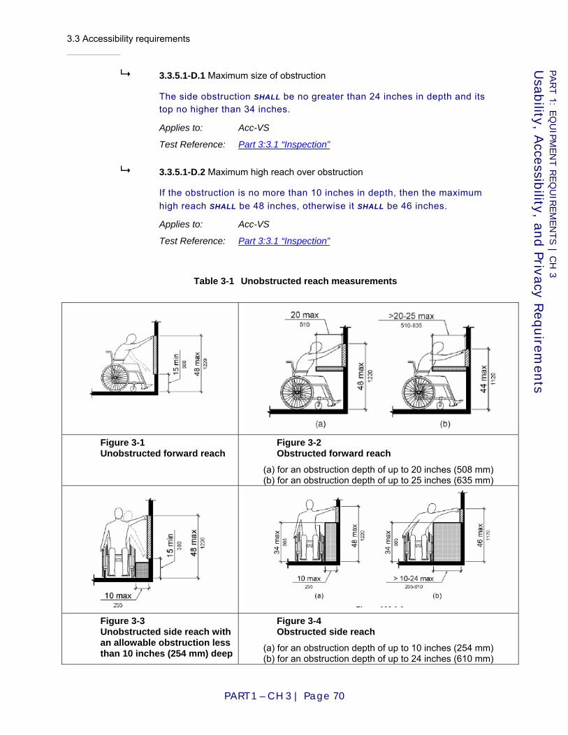
3.3 Accessibility requirements
PART 1 – CH 3 | Page 70
PART 1: E
QU
IPM
EN
T R
EQ
UIR
EM
EN
TS | C
H 3
Usab
ility, Accessib
ility, and Privacy R
equirem
ents
3.3.5.1-D.1 Maximum size of obstruction
The side obstruction SHALL be no greater than 24 inches in depth and its top no higher than 34 inches.
Applies to: Acc-VS
Test Reference: Part 3:3.1 “Inspection”
3.3.5.1-D.2 Maximum high reach over obstruction
If the obstruction is no more than 10 inches in depth, then the maximum high reach SHALL be 48 inches, otherwise it SHALL be 46 inches.
Applies to: Acc-VS
Test Reference: Part 3:3.1 “Inspection”
Table 3-1 Unobstructed reach measurements
Figure 3-1 Unobstructed forward reach
Figure 3-2 Obstructed forward reach
(a) for an obstruction depth of up to 20 inches (508 mm) (b) for an obstruction depth of up to 25 inches (635 mm)
Figure 3-3 Unobstructed side reach with an allowable obstruction less than 10 inches (254 mm) deep
Figure 3-4 Obstructed side reach
(a) for an obstruction depth of up to 10 inches (254 mm) (b) for an obstruction depth of up to 24 inches (610 mm)
3.3 Accessibility requirements
PART 1 – CH 3 | Page 71
PART 1: E
QU
IPM
EN
T R
EQ
UIR
EM
EN
TS | C
H 3
Usab
ility, Accessib
ility, and Privacy R
equirem
ents
3.3.6 Hearing
These requirements specify the features of the accessible voting station designed to assist voters with hearing disabilities.
3.3.6-A Reference to audio requirements
The accessible voting station SHALL incorporate the features listed under Requirement Part 1:3.3.3-C for voting equipment that provides audio presentation of the ballot.
Applies to: Acc-VS
Test Reference: Part 3:3.2 “Functional Testing”
D I S C U S S I O N
Note especially the requirements for volume initialization and control.
3.3.6-B Visual redundancy for sound cues
If the voting system provides sound cues as a method to alert the voter, the tone SHALL be accompanied by a visual cue, unless the station is in audio-only mode.
Applies to: Acc-VS
Test Reference: Part 3:3.2 “Functional Testing”
D I S C U S S I O N
For instance, the voting equipment might beep if the voter attempts to overvote. If so, there would have to be an equivalent visual cue, such as the appearance of an icon, or a blinking element. If the voting system has been set to audio-only mode, there would be no visual cue.
3.3.6-C No electromagnetic interference with hearing devices
No voting equipment SHALL cause electromagnetic interference with assistive hearing devices that would substantially degrade the performance of those devices. The voting equipment, considered as a wireless device, SHALL achieve at least a category T4 rating as defined by [ANSI01] American National Standard for Methods of Measurement of Compatibility between Wireless Communications Devices and Hearing Aids, ANSI C63.19.
Applies to: Voting device
Test Reference: Part 3:3.2 “Functional Testing”
D I S C U S S I O N
"Hearing devices" include hearing aids and cochlear implants.

3.3 Accessibility requirements
PART 1 – CH 3 | Page 72
PART 1: E
QU
IPM
EN
T R
EQ
UIR
EM
EN
TS | C
H 3
Usab
ility, Accessib
ility, and Privacy R
equirem
ents
3.3.7 Cognition
These requirements specify the features of the accessible voting station designed to assist voters with cognitive disabilities.
3.3.7-A General support for cognitive disabilities
The accessible voting station SHOULD provide support to voters with cognitive disabilities.
Applies to: Acc-VS
Test Reference: Part 3:3.2 “Functional Testing”
D I S C U S S I O N
Because of the highly varied nature of disabilities falling within the "cognitive" category, there are no design features uniquely aimed at helping those with such disabilities. However, many of the features designed primarily for other disabilities and for general usability are also highly relevant to these voters:
1. the synchronization of audio with the displayed screen information (Requirement Part 1:3.3.2-D);
2. the general cognitive usability requirements (Requirement Part 1:3.2.4) and, in particular, the use of plain language (Requirement Part 1:3.2.4-C);
3. large font sizes and legibility of paper (Requirement Part 1:3.2.5-E and Part 1:3.2.5-G); and
4. the ability to control various aspects of the audio presentation (Requirement Part 1:3.3.3-B and Part 1:3.3.3-C) such as pausing, repetition, and speed.
3.3.8 English proficiency
These requirements specify the features of the accessible voting station designed to assist voters who lack proficiency in reading English.
3.3.8-A Use of ATI
For voters who lack proficiency in reading English, the voting equipment SHALL provide an audio interface for instructions and ballots as described in Part 1:3.3.3-B.
Applies to: Acc-VS
Test Reference: Part 3:3.2 “Functional Testing”
3.3 Accessibility requirements
PART 1 – CH 3 | Page 73
PART 1: E
QU
IPM
EN
T R
EQ
UIR
EM
EN
TS | C
H 3
Usab
ility, Accessib
ility, and Privacy R
equirem
ents
3.3.9 Speech
3.3.9-A Speech not to be required by equipment
No voting equipment SHALL require voter speech for its operation.
Applies to: Voting system
Test Reference: Part 3:3.2 “Functional Testing”
D I S C U S S I O N
This does not preclude voting equipment from offering speech input as an option, but speech must not be the only means of input.
3.3 Accessibility requirements
PART 1 – CH 3 | Page 74
PART 1: E
QU
IPM
EN
T R
EQ
UIR
EM
EN
TS | C
H 3
Usab
ility, Accessib
ility, and Privacy R
equirem
ents
4.1 Overview
PART 1 – CH 4 | Page 75
PART 1: E
QU
IPM
EN
T R
EQ
UIR
EM
EN
TS | C
H 4
Secu
rity and A
udit A
rchitectu
re
Chapter 4: Security and Audit Architecture
4.1 Overview
This chapter contains requirements pertaining to independent voter-verifiable record (IVVR) voting systems to ensure that they can be audited independently of their software. As part of this material, this chapter also includes basic requirements for voter-verifiable paper audit trail voting systems (VVPATs) that have been updated from [VVSG2005].
The requirements in this chapter are necessary to ensure that IVVR systems fully meet the definition of software independence. IVVR systems in general meet the SI definition because they produce two records that can be compared against each other: (1) the electronic version of the CVR, and (2) the IVVR summary of the electronic CVR that the voter has the opportunity to compare against the voting system’s display of the electronic CVR.
However, additional requirements are still needed for IVVR systems to ensure that the audits can be independently verifiable. IVVR records must be constructed carefully for this purpose; IVVR systems must produce other supporting records for the purposes of verifying that the number of electronic CVRs is correct and for the purposes of being able to verify that the records are indeed authentic and have been produced by the appropriate authorized voting systems. Accordingly, this chapter contains the following sections:
♦ Section 4.2: high-level requirements to ensure that IVVR voting systems produce records that can be used in certain general types of independent audits;
♦ Section 4.3: requirements for electronic records created and exported by IVVR voting systems; and
♦ Section 4.4: requirements for IVVR and for VVPAT and PCOS voting systems that use voter-verifiable paper records (VVPR), i.e., paper IVVR.
4.2 Requirements for Supporting Auditing
This section presents requirements on voting system devices to provide the capability for certain general types of audits described herein. The audits work together to ensure independent agreement between what is presented to the voters by the IVVR vote-capture devices, what is counted by tabulators, and what is reported by the EMS as a final ballot count and vote totals.
Note: This section does not include requirements on election officials to perform the audits described herein. Audits are considered part of election procedures and cannot be mandated by the VVSG. The requirements in this section focus on
4.2 Requirements for Supporting Auditing
PART 1 – CH 4 | Page 76
PART 1: E
QU
IPM
EN
T R
EQ
UIR
EM
EN
TS | C
H 4
Secu
rity and A
udit A
rchitectu
re
ensuring that IVVR voting systems produce records that are capable of being used in independent audits so that the voting systems will meet . It is left to election procedures to mandate whether the audits are to be performed.
Auditing procedures for IVVR systems imposes requirements on the voting system in several ways, including:
A. Some auditing procedures need to reconcile that the number of electronic CVRs captured by the voting system is indeed accurate, that this number agrees with the number of voters who have cast a ballots.
B. Some auditing procedures need specific information or behavior from voting systems in order to be possible or practical. For example, hand auditing the correspondence between IVVR and electronic CVRs is only possible if the voting system produces IVVR and electronic CVRs that include the same information.
C. Some auditing procedures require certain assurances about the operation of the voting devices in order to be meaningful. For example, the hand audit of the paper and electronic records from VVPATs is meaningful only because voters had the opportunity to both view and verify the paper records.
Accordingly, there are three general types of audits anticipated for IVVR voting systems to ensure that the electronic CVRs and IVVRs fully agree. These are as follows:
1. Verifying that the number of voters for each reporting context and ballot style agrees with the totals reported by the tabulator. This guards against a tabulator reporting more votes than it had voters, or reassigning some voters to the wrong precinct or ballot style. This type of audit is referred to here as the pollbook audit.
2. Verifying by hand that the IVVR agree with the reported totals from the tabulator. This guards against a voting device silently misrecording votes.
3. Comparing IVVR vote-capture device records against final ballot and vote totals to verify that the electronic records from the tabulators agree with the final reported totals. This guards against a compromised EMS misreporting the final results.
4.2.1 Pollbook audit
The purpose of the pollbook audit is to verify that:
♦ The total number of ballots recorded by the voting system in some location is the same as the total number of voters who have cast ballots.
♦ The total number of ballots recorded for each ballot configuration, and for each reporting context, is the same as the number of such voters authorized to vote with that ballot configuration, in those reporting contexts.
4.2 Requirements for Supporting Auditing
PART 1 – CH 4 | Page 77
PART 1: E
QU
IPM
EN
T R
EQ
UIR
EM
EN
TS | C
H 4
Secu
rity and A
udit A
rchitectu
re
This mitigates the threat that a tampered tabulator (such as a PCOS scanner) might have inserted or deleted votes, and also the threat that it may have assigned some voters the wrong reporting context or ballot configuration to prevent them voting in certain elections or to dilute the effect of their votes.
4.2.1-A Voting system, support for pollbook audit
The voting system SHALL support a secure pollbook audit that can detect differences in ballot counts between the pollbooks, vote-capture devices, activation devices, and tabulators.
Applies to: Voting system
Test Reference: Part 3:4.3 “Verification of Design Requirements”, 5.2 “Functional Testing”, 5.3 “Benchmarks”
D I S C U S S I O N
The pollbook audit is critical for blocking various threats on voting systems, such as simply inserting additional votes into the voting system. This requirement and its subrequirement are high-level “goal” requirements whose aim is to ensure that the voting system produces records that are adequate and usable by election officials for conducting pollbook audits. This requirement is supported by various other requirements for general reporting and in Part 1:4.3 “Electronic Records”. It can be tested as part of the volume tests discussed in Part 1:7.8 “Reporting” and Part 3:5.3 “Benchmarks”; this type of testing may be useful for assessing the usability of the audit records for typical election environments.
Source: [VVSG2005] I.2.1.5.1
4.2.1-A.1 Records and reports for pollbook audit
Vote-capture devices, activation devices, and tabulators SHALL support production and retention of records and reports that support the pollbook audit.
Applies to: Vote-capture device, Tabulator, Activation device
Test Reference: Part 3:5.2 “Functional Testing”, 5.3 “Benchmarks”
D I S C U S S I O N
The pollbook audit is only practical when the number of ballots, and of each distinct type of ballot, is available from both the pollbooks and the tabulators.
Source: [VVSG2005] I.5.4.4
4.2.2 Hand audit of IVVR record
The hand audit of verifies that the IVVRs and reported totals from a tabulator are in agreement. The hand audit addresses the threats that the voting device might record and report results electronically that disagree with the choices indicated by the voter.
4.2 Requirements for Supporting Auditing
PART 1 – CH 4 | Page 78
PART 1: E
QU
IPM
EN
T R
EQ
UIR
EM
EN
TS | C
H 4
Secu
rity and A
udit A
rchitectu
re
4.2.2-A IVVR, support for hand audit
The voting system SHALL support a hand audit of IVVRs that can detect differences between the IVVR and the electronic CVR.
Applies to: Voting system
Test Reference: Part 3:5.2 “Functional Testing”, 5.3 “Benchmarks”
D I S C U S S I O N
Hand auditing verifies the reported electronic records; IVVR offer voters an opportunity to discover attempts to misrecord their votes on the IVVR, and the hand audit ensures that devices that misrecord votes on the electronic record but not the IVVR are very likely to be caught.
Hand auditing draws on the results from the pollbook audit and the ballot count and vote total. For example, the hand audit cannot detect insertion of identical invalid votes in both paper and electronic records in a VVPAT, but the pollbook audit can detect this since it reconciles the electronic CVR count with the number of voters who cast ballots. Similarly, the hand audit cannot detect that the summary of reported ballots from the tabulator or polling place agrees with the final election result, but this can be checked by the ballot count and vote total audit.
This requirement and its subrequirement are high-level “goal” requirements whose aim is to ensure that the voting system produces records that are adequate and usable by election officials for conducting audits of IVVR records by hand. It can be tested as part of the volume tests discussed in Part 1:7.8 “Reporting” and Part 3:5.3 “Benchmarks”; this type of testing may be useful for assessing the usability of the audit records for manual audits in typical election volumes.
Source: [VVSG2005] I.2.1.5.1
4.2.2-A.1 IVVR, information to support hand auditing
IVVR vote-capture devices and tabulators SHALL provide information to support hand auditing of IVVR.
Applies to: IVVR vote-capture device, Tabulator
Test Reference: Part 3:4.3 “Verification of Design Requirements”, 5.2 “Functional Testing”, 5.3 “Benchmarks”
D I S C U S S I O N
The electronic summary information from the DRE or scanner and the IVVRs, must contain sufficient information to carry out the hand audit. Because the hand audit may be carried out at different reporting contexts (for example, a specific tabulator or a whole precinct or polling place may be selected for audit), the voting system must be able to provide reports that support hand auditing at each of the different reporting contexts.
Source: [VVSG2005] I.5.4.4
4.2 Requirements for Supporting Auditing
PART 1 – CH 4 | Page 79
PART 1: E
QU
IPM
EN
T R
EQ
UIR
EM
EN
TS | C
H 4
Secu
rity and A
udit A
rchitectu
re
4.2.3 Ballot count and vote total audit
The purpose of this process is to verify that the ballot counts and vote totals reported by EMSs are correct. This guards against the threat that the EMS used to produce the final results might be compromised. Please see Part 1:7.8 “Reporting”, Reporting, for information on ballot count and vote total reports.
4.2.3-A EMS, support for reconciling voting device totals
The EMS SHALL support the reconciliation of the tabulator totals and the final ballot count and vote totals according to the following:
a. A tabulator whose reported totals are not correctly included in the ballot count and vote total reports, and which is audited, SHALL be detectable;
b. A difference between the final ballot count and vote totals and the audit records for a tabulator that is audited SHALL be detectable;
c. The disagreements in records SHALL be detectable even when the election management software is acting in a malicious way; and
d. The EMS SHALL be able to provide reports that support ballot count and vote total auditing for different reporting contexts.
Applies to: EMS
Test Reference: Part 3:4.3 “Verification of Design Requirements”, 5.2 “Functional Testing”, 5.3 “Benchmarks”
D I S C U S S I O N
This auditing process, part of the canvassing procedure, is a defense against problematic behavior by the voting device computing the final election ballot count and vote totals. Section 4.3 includes requirements to make this procedure easier to carry out and to add cryptographic protection to the records produced by the voting devices. One complication in making a full voting system support this procedure is the likely mixing of old and new voting devices in a full voting system.
When the specific reporting context used is the same as for the hand audit, the ballot count and vote totals audit and hand audit together verify that the votes that appear on the IVVR correspond to the votes that are reported in the final election result.
This requirement and its subrequirement can be tested as part of the volume tests discussed in Part 1 Section 7.8 and Part 3 Section 5.3.
4.2.3-B Records for ballot count/vote total audit
Vote-capture devices, tabulators, and activation devices SHALL produce records that support the ballot count and vote total audit.
Applies to: Vote-capture device, Tabulator, Activation device
Test Reference: Part 3:5.2 “Functional Testing”, 5.3 “Benchmarks”
D I S C U S S I O N
This auditing step requires that electronic summary records from voting devices can be reconciled with the final election ballot count and vote total reports. The

4.2 Requirements for Supporting Auditing
PART 1 – CH 4 | Page 80
PART 1: E
QU
IPM
EN
T R
EQ
UIR
EM
EN
TS | C
H 4
Secu
rity and A
udit A
rchitectu
re
ballot count and vote total records must thus be capable of breaking down totals by voting device as well as by precinct and polling place.
Sections 4.3 and 4.4 specify content of the IVVR and electronic records, respectively, needed to support this requirement.
4.2.4 Additional behavior to support auditing for accessible IVVR voting systems
Another issue in the operational behavior of accessible IVVR voting systems needs to be considered to ensure that they are software independent and independently auditable.
Accessible IVVR systems that provide an audio readback of the IVVR (e.g., a VVPAT’s VVPR) may use the same software base to do the following:
♦ Permit the voter to make ballot choices;
♦ Create the IVVR of the voter’s ballot choices; and
♦ Read back to the voter the IVVR.
To ensure that the accessible IVVR vote-capture device is interacting with the voter properly and recording voting choices accurately, the accessible IVVR voting system must allow for all voters to
A. Cast their votes using assistive technology such as the audio-tactile interface even if the voters do not require this technology to be able to vote, and
B. Verify the IVVR record with the audio readback.
Election procedures must actually ensure that sufficient numbers of voters use the accessible IVVR voting system in this way to ensure that the audio readback matches the IVVR record. These voters are able to confirm that both the IVVR and audio ballots contain the same information. This guards against the voting device selectively misrecording votes of voters with disabilities. For the purposes of discussion in this section, this type of voter behavior is referred to as Observational Testing.
4.2.4-A IVVR vote-capture device, observational testing
IVVR vote-capture devices that support assistive technology SHALL support observational testing.
Applies to: IVVR vote-capture device ^ Acc-VS
Test Reference: Part 3:5.2 “Functional Testing”
D I S C U S S I O N
Blind, partial vision, and non-written languages voters may not be able to directly verify the IVVR produced by the voting system. This may be because they are using the audio-tactile interface, magnified screen images, or other assistive technology. This raises the possibility that a malicious IVVR vote-capture device
4.3 Electronic Records
PART 1 – CH 4 | Page 81
PART 1: E
QU
IPM
EN
T R
EQ
UIR
EM
EN
TS | C
H 4
Secu
rity and A
udit A
rchitectu
re
could modify these voters’ votes by simply recording the wrong votes on both electronic records and IVVRs. Observational testing provides a defense by using volunteer voters. When observational testing is in use, a malicious IVVR vote-capture device cannot safely assume that a voter using the audio-tactile interface will be unable to check the IVVR record.
Source: New requirement
4.2.4-B IVVR vote-capture device, authentication for observational testing
The mechanism for authenticating the voter to the accessible IVVR vote-capture device SHALL NOT allow the IVVR vote-capture device to distinguish whether a voter is performing observational testing. The pollworker issuing the ballot activation for voters performing observational testing SHALL NOT be capable of signaling to the IVVR vote-capture device that it is being tested.
Applies to: IVVR vote-capture device ^ Acc-VS, Activation device
Test Reference: Part 3:5.2 “Functional Testing”
D I S C U S S I O N
Observational testing would not detect attacks if the IVVR vote-capture device were somehow alerted that the voter was carrying out observational testing. Thus, the authentication mechanism must not permit the device to discover this fact.
Source: New requirement
4.3 Electronic Records
In order to support independent auditing, an IVVR voting system must be able to produce electronic records that contain the needed information in a secure and usable manner. Typically, this includes records such as:
♦ Vote counts;
♦ Counts of ballots recorded;
♦ Information that identifies the electronic record;
♦ Event logs and other records of important events or details of how the election was run on this device; or
♦ Election archive information.
By ensuring that certain records are produced, secured, and exported, many threats to security can be reduced, including tampering with electronic records in transit from the polling place to the tabulation center, tampering with the operation of the tabulation center, or altering election records after the totals are determined.
There are three types of requirements on electronic records in this section:
1. Requirements for how electronic records must be protected cryptographically;
2. Requirements for which electronic records must be produced by tabulators; and

4.3 Electronic Records
PART 1 – CH 4 | Page 82
PART 1: E
QU
IPM
EN
T R
EQ
UIR
EM
EN
TS | C
H 4
Secu
rity and A
udit A
rchitectu
re
3. Requirements for printed reports to support auditing steps.
4.3.1 Records produced by voting devices
The following requirements apply to records produced by the voting system for any exchange of information between devices, support of auditing procedures, or reporting of final results. This includes the electronic version of all reports specified in Part 1:5.1 “Cryptography”.
4.3.1-A All records capable of being exported
The voting system SHALL provide the capability to export its electronic records to files.
Applies to: Voting system
Test Reference: Part 3:5.2 “Functional Testing”
D I S C U S S I O N
The exported format for the records must meet the requirements for data export in Part 1:6.6 “Integratability and Data Export/Interchange”.
Source: New requirement
4.3.1-B All records capable of being printed
The voting system SHALL provide the ability to produce printed forms of its electronic records.
a. The printed forms SHALL retain all required information as specified for each record type other than digital signatures;
b. The printing MAY be done from a different device than the voting device that produces the electronic record; and
c. It shall be possible to print records produced by the central tabulator or EMS on a different device.
Applies to: Voting system
Test Reference: Part 3:5.2 “Functional Testing”
D I S C U S S I O N
Printed versions of all records in this chapter are either necessary or extremely helpful to support required auditing steps. Ensuring that the printing can be done from a machine other than the tabulator used to compute the final totals for the election supports the vote total audit, and is a logical consequence of the requirement for a fully open record format.
Source: [VVSG2005] I.2.1.5.1-a
4.3.1-C Cryptographic protection of records from voting devices
Electronic records SHALL be digitally signed with the Election Signature Key.
Applies to: Voting system
Test Reference: Part 3:4.5 “Source Code Review”, 5.2 “Functional Testing”
4.3 Electronic Records
PART 1 – CH 4 | Page 83
PART 1: E
QU
IPM
EN
T R
EQ
UIR
EM
EN
TS | C
H 4
Secu
rity and A
udit A
rchitectu
re
D I S C U S S I O N
The digital signatures address the threat that the records might be tampered with in transit or in storage. When combined with the Election Public Key Certificate, the signature also addresses the threat that a legitimate electronic record might be misinterpreted as coming from the wrong voting device or scanner. The use of per-election keys to sign these records addresses the threat that a compromise of a voting device before or after election day might permit production of a false set of records for the election, which could then be reported to the EMS.
This requirement mandates a similar optional recommendation in [VVSG2005] 7.9.3-d which applies only to VVPATs. There is no requirement that states that all electronic records must be signed in the [VVSG2005].
Source: [VVSG2005] I.7.9.3-d
4.3.2 Records produced by tabulators
The following requirements apply to records produced by tabulators, such as DREs and optical scanners, for exchange of information between devices, transmission of results to the EMS, support of auditing procedures, or reporting of intermediate election results.
4.3.2-A Tabulator, summary count record
Each tabulator SHALL produce a Tabulator Summary Count record including the following:
a. Device unique identifier from the X.509 certificate; b. Time and date of summary record; c. The following, both in total and broken down by ballot configuration
and precinct: 1. Number of read ballots; 2. Number of counted ballots; 3. Number of rejected electronic CVRs; and 4. For each N-of-M (including 1-of-M) or cumulative voting contest
appearing in any ballot configuration handled by the tabulator: I. Number of counted ballots that included that contest, per the
definition of K(j,r,t) in Part 1:Table 8-2; II. Vote totals for each non-write-in contest choice per the
definition of T(c,j,r,t) in Part 1:Table 8-2; III. Number of write-in votes; IV. Number of overvotes per the definition of O(j,r,t) in Part
1:Table 8-2; and V. Number of undervotes per the definition of U(j,r,t) in Part
1:Table 8-2. In producing this summary count record, the tabulator SHALL assume that no provisional or challenged ballots are accepted.
Applies to: Tabulator
Test Reference: Part 3:4.5 “Source Code Review”, 5.2 “Functional Testing”

4.3 Electronic Records
PART 1 – CH 4 | Page 84
PART 1: E
QU
IPM
EN
T R
EQ
UIR
EM
EN
TS | C
H 4
Secu
rity and A
udit A
rchitectu
re
D I S C U S S I O N
The Tabulator Summary Count Record is essentially an estimated summary report from the viewpoint of the individual tabulator, for auditing purposes. Since the eventual disposition of provisional ballots, challenged ballots, and write-in votes is unknown at the close of polls, arbitrary assumptions are made in order to make a summary possible. All provisional and challenged ballots are assumed rejected, and all write-in votes are effectively aliased to a single contest choice that is not one of the choices "on the ballot." The quantities provided for each contest should balance in the sense that
N × K = sum of non-write-in vote totals (T) + write-ins + overvotes (O) + undervotes (U).
In addition to the reporting context corresponding to the tabulator itself, reporting contexts corresponding to the different ballot configurations handled by that tabulator are synthesized. These contexts are quite narrow in scope as they include only the ballots of a specific configuration that were counted by a specific tabulator. The tabulator is not required to handle the complexities of reporting contexts that are outside of its scope.
This record is sufficient to support random audits of paper records. The record will not contain the results of election official review of review-required ballots, so auditors can use this record to verify that the number of these ballots is correct, but will need to do further steps to verify that these ballots were handled correctly. This record can be used to verify a correct result from a system under parallel testing. This record can be used to randomly check electronic totals, when the final results are given broken out by voting system or scanner. When used in the Ballot Count and Vote Total Audit, this record blocks the class of attacks that involves tampering with the EMS computer used to compute the final totals. The tabulator summary could in principle be published for each voting system, along with corrected final totals for each precinct and for absentee ballots, to show how the final election outcomes were computed, though care would have to be taken to avoid violations of voter privacy.
For auditing, this record must be output in a human-readable format, such as a printed report.
This requirement clarifies [VVSG2005] I.2.4.3, which describes the vote data summary reports that all voting systems are required to produce. While [VVSG2005] I.2.4.3 applies to voting systems as a whole, this requirement specifically requires that all vote tabulators produce such a report.
Source: [VVSG2005] I.2.4.3
4.3.2-B Tabulator, summary count record handling
The tabulator SHALL handle the summary count record according to the following:
a. The record SHALL be transmitted to the EMS with the other electronic records;
b. It SHALL be stored in the election archive, if available; and c. It SHALL be stored in the voting systems event log.
4.3 Electronic Records
PART 1 – CH 4 | Page 85
PART 1: E
QU
IPM
EN
T R
EQ
UIR
EM
EN
TS | C
H 4
Secu
rity and A
udit A
rchitectu
re
Applies to: Tabulator
Test Reference: Part 3:5.2 “Functional Testing”
Source: New requirement
4.3.2-C Tabulator, collection of ballot images record
Tabulators SHOULD produce a record of ballot images that includes: a. Time and date of creation of complete ballot image record; and b. Ballot images recorded in randomized order by the DRE for the
election. For each voted ballot, this includes: 1. Ballot configuration and counting context; 2. Whether the ballot is accepted or rejected; 3. For each contest:
I. The choice recorded, including undervotes and write-ins; and
II. Any information collected by the vote-capture device electronically about each write-in;
4. Information specifying whether the ballot is provisional, and providing unique identifier for the ballot, as well as provisional category information required to support Requirement Part 1:7.7.2-A.6.
Applies to: Tabulator
Test Reference: Part 3:5.2 “Functional Testing”
D I S C U S S I O N
This record is not required for auditing, however it is useful.
Source: New requirement
4.3.2-C.1 DRE, collection of ballot images record
DREs SHALL produce a record of ballot images that includes: a. Time and date at poll closing; and b. Ballot images recorded in randomized order by the DRE for the
election. For each voted ballot, this includes: 1. Ballot configuration and counting context; 2. Whether the ballot is accepted or rejected; 3. For each contest:
I. The choice recorded, including undervotes and write-ins; and
II. Any information collected by the vote-capture device electronically about each write-in;
4. Information specifying whether the ballot is provisional, and providing unique identifier for the ballot, as well as provisional category information required to support Requirement Part 1:7.7.2-A.6.
Applies to: DRE
Test Reference: Part 3:5.2 “Functional Testing”
D I S C U S S I O N
DREs already contain the information to create the ballot image records.

4.3 Electronic Records
PART 1 – CH 4 | Page 86
PART 1: E
QU
IPM
EN
T R
EQ
UIR
EM
EN
TS | C
H 4
Secu
rity and A
udit A
rchitectu
re
This requirement extends [VVSG2005] I.7.9.3-b by requiring an audit record containing electronic ballot images, and specifies other information that must be contained in this record. This requirement extends [VVSG2005] I.7.9.3-e by requiring that VVPATs produce an audit record containing electronic ballot images. [VVSG2005] I.7.9.3-e only requires that electronic ballot images be exportable for auditing purposes.
Source: [VVSG2005] I.7.9.3-b, I.7.9.3-e
4.3.2-C.2 Tabulator. collection of cast votes handling
Tabulators that produce the collection of ballot images record SHALL handle the record according to the following:
a. The record SHALL be transmitted to the EMS with the other electronic records;
b. It SHALL be stored in the election archive, if available; and c. It SHALL be stored in the voting systems event log.
Applies to: Tabulator
Test Reference: Part 3:5.2 “Functional Testing”
Source: New requirement
4.3.2-D Tabulator, electronic records event log record handling
The tabulator SHALL digitally sign the event log, transmit the signed event log to an EMS, and retain a record of the transmission.
Applies to: Tabulator
Test Reference: Part 3:5.2 “Functional Testing”
D I S C U S S I O N
The EMS can verify that the event log record is received and that the digital signature and per election key and certificate are valid.
Source: New requirement
4.3.3 Records produced by the EMS
The following requirements apply to the records produced by an EMS. EMSs include both DREs used as accumulators in the polling place, called a Precinct EMS, as well as EMSs used as jurisdiction-wide accumulators. All of the requirements for tabulators apply to EMSs. This section addresses additional requirements based on an EMSs role as an accumulator of ballot counts and vote totals.
4.3.3-A EMS tabulator summary count record
The EMS Tabulator Summary Count Record SHALL include: a. Unique identifiers for each tabulator contained in the summary; b. For tabulators with public keys:
1. The public key for each tabulator in the summary;
4.3 Electronic Records
PART 1 – CH 4 | Page 87
PART 1: E
QU
IPM
EN
T R
EQ
UIR
EM
EN
TS | C
H 4
Secu
rity and A
udit A
rchitectu
re
2. The Election Signature Key certification and closeout record; and 3. Signed tabulator summary count record.
c. Summary ballot counts and vote totals by tabulator, precinct, and polling place. 1. Precinct totals include subtotals from each tabulator used in the
precinct. Applies to: EMS
Test Reference: Part 3:4.5 “Source Code Review”, 5.2 “Functional Testing”
D I S C U S S I O N
Requirements in Part 1 Section 7.8 ensure that the EMS is capable of producing a report containing this information. This report is required to allow checking of the final ballot counts and vote totals, based on their agreement with local totals, without relying on the correct operation of equipment and execution of procedures at the tabulation center. The goal is to provide cryptographic support for a process that is currently done in a manual, procedural way, which may be subject to undetected error or tampering. This record can be used to detect most problems at the tabulation center. Item c.1 is needed for cases when a tabulator, such as a DRE, contains votes from multiple precincts. Note: The requirement supports older voting systems to allow for transitioned upgrades of fielded equipment.
This requirement extends [VVSG2005] I.2.4.3; this requirement specifically requires that each tabulation center EMS produce this report.
Source: [VVSG2005] I.2.4.3
4.3.3-A.1 Tabulator, report combination for privacy
The EMS shall be capable of combining tabulator reports to protect voter privacy in cases when there are tabulators with few votes.
Applies to: EMS
Test Reference: Part 3:5.2 “Functional Testing”
4.3.3-B EMS, precinct summary count records
The EMS SHALL produce a report for each precinct including: a. Each tabulator included in the precinct with its unique identifier; b. Number of read ballots; c. Number of counted ballots; d. Number of rejected electronic CVRs; and e. For each N-of-M (including 1-of-M) or cumulative voting contest
appearing in any ballot configuration handled by the tabulator: 1. Number of counted ballots that included that contest, per the
definition of K(j,r,t) in Part 1:Table 8-2; 2. Vote totals for each non-write-in contest choice per the definition
of T(c,j,r,t) in Part 1:Table 8-2; and 3. Number of write-in votes
Applies to: EMS
Test Reference: Part 3:4.5 “Source Code Review”, 5.2 “Functional Testing”

4.3 Electronic Records
PART 1 – CH 4 | Page 88
PART 1: E
QU
IPM
EN
T R
EQ
UIR
EM
EN
TS | C
H 4
Secu
rity and A
udit A
rchitectu
re
D I S C U S S I O N
This report supports hand auditing of paper records against the final totals, the ballot count and vote totals audit, and the pollbook audit.
This requirement extends [VVSG2005] I.2.4.3; this requirement specifically requires that each tabulation center EMS produce the report.
Source: [VVSG2005] I.2.4.3
4.3.3-C EMS, precinct adjustment record
The EMS SHALL produce a report showing the changes made to each contest based on the resolution of provisional ballots, challenged ballots, write-in choices, and the date and time of the report.
Applies to: EMS
Test Reference: Part 3:5.2 “Functional Testing”
D I S C U S S I O N
This report may be produced more than once during the course of an election as the resolution of provisional ballots, challenged ballots, and write-in choices are processed. This report can be used to support pollbook audit showing that number of ballots processed do not exceed the total recorded by the tabulator as well as to support the ballot total and vote count audit. Many jurisdictions resolve provisional and challenged ballots in groups to protect voter privacy.
Source: New requirement
4.3.4 Digital signature verification
4.3.4-A Tabulator, verify signed records
For each tabulator producing electronic records, the EMS SHALL verify: a. The Election Public Key Certificate associated with the record is
valid for the current election, using the public key of the tabulator to verify the certificate as specified in Part 1:5.1 “Cryptography”;
b. The election ID and timestamp of the record agrees with the current election and the values in the Election Public Key Certificate; and
c. The digital signature on the record is correct, using the Election Public Key to verify it.
Applies to: EMS
Test Reference: Part 3:4.5 “Source Code Review”, 5.2 “Functional Testing”
D I S C U S S I O N
The digital signature applied to the electronic records from the voting devices is only useful if it is verified before the EMS accepts electronic records. A DRE that accumulates results at a precinct or polling place is serving as a precinct level EMS.
Source: New requirement
4.4 Independent Voter-Verifiable Records
PART 1 – CH 4 | Page 89
PART 1: E
QU
IPM
EN
T R
EQ
UIR
EM
EN
TS | C
H 4
Secu
rity and A
udit A
rchitectu
re
4.3.5 Ballot counter
4.3.5-A Ballot counter
Tabulators and vote-capture devices SHALL maintain a count of the number of ballots read at all times during a particular test cycle or election.
Applies to: Tabulator, Vote-capture device
Test Reference: Part 3:3.2 “Functional Testing”
D I S C U S S I O N
For auditability, the ballot count must be maintained (incremented each time a ballot is read) rather than calculated on demand (by counting the ballots currently in storage). This requirement restates [VVSG2005] I.2.1.8.
Source: Implied by design requirements in [VSS2002] I.2.2.9, [VVSG2005] I.2.1.8
4.3.5-B Ballot counter, availability
Tabulators SHALL enable election judges to determine the number of ballots read at all times during a particular test cycle or election without disrupting any operations in progress.
Applies to: Tabulator, Vote-capture device
Test Reference: Part 3:3.2 “Functional Testing”
D I S C U S S I O N
[VSS2002] I.2.4 refers to separate “election counter” and “life-cycle counter;” the latter was an error (intended to delete). This requirement clarifies [VVSG2005] I.2.1.8 by stating that reading the ballot counter must not disrupt voting system operations.
Source: Implied by design requirements in [VSS2002] I.2.2.9, I.2.1.8
4.4 Independent Voter-Verifiable Records
This chapter contains requirements for voting systems that produce and use independent voter-verifiable records (IVVR). IVVR are generally understood to mean voter-verifiable paper records (VVPR); however non-paper IVVR, once developed, could be used to still satisfy these requirements. There are two broad categories of paper-based IVVR, i.e., VVPR:
♦ VVPATs couple an electronic voting device with a printer. The voter makes selections on the voting device, but is given the opportunity to review and verify choices on a paper record. The paper record may be a continuous roll or cut sheets.
♦ Optical scan voting systems use paper ballots that are human-readable and may be marked by either hand or device, along with an

4.4 Independent Voter-Verifiable Records
PART 1 – CH 4 | Page 90
PART 1: E
QU
IPM
EN
T R
EQ
UIR
EM
EN
TS | C
H 4
Secu
rity and A
udit A
rchitectu
re
electronic scanner that checks the ballot for problems such as under- and over-votes, and also records the votes.
For all IVVR systems, the records are available to the voter to review and verify, and these records are retained for later auditing or recounts as needed. This chapter addresses the use of the records for auditing and security. The chapter first presents the requirements for IVVR systems and then presents specific requirements for VVPR systems.
4.4.1 General requirements
Voter-verifiable records exist to provide an independent record of the voter’s choices that can be used to verify the correctness of the electronic record produced by the voting device.
4.4.1-A IVVR vote-capture device, IVVR creation
The IVVR vote-capture device shall create an independent voter verifiable record.
Applies to: IVVR vote-capture device
Test Reference: Part 3:5.2 “Functional Testing”
D I S C U S S I O N
This requirement is further defined by its subrequirements. Its purpose is to ensure that a single IVVR meets all requirements and all properties as outlined in the following subrequirements.
Source: New requirement
4.4.1-A.1 IVVR vote-capture device, IVVR direct verification by voters
IVVR vote-capture devices SHALL create an IVVR that voters can verify (a) without software, or (b) without programmable devices excepting assistive technology.
Applies to: IVVR vote-capture device
Test Reference: Part 3:5.2 “Functional Testing”
D I S C U S S I O N
The exclusion of software or programmable devices from the voter verification process is necessary for the system to be software independent. It suffices to meet this requirement that most voters can review the record directly. Voters who use some assistive technologies may not be able to directly review the record. This requirement allows for observational testing to be able to determine whether the assistive technology is operating without error or fraud.
Source: New requirement
4.4 Independent Voter-Verifiable Records
PART 1 – CH 4 | Page 91
PART 1: E
QU
IPM
EN
T R
EQ
UIR
EM
EN
TS | C
H 4
Secu
rity and A
udit A
rchitectu
re
4.4.1-A.2 IVVR vote-capture device, IVVR direct review by election officials
IVVR vote-capture devices SHALL create an IVVR that election officials and auditors can review without software or programmable devices.
Applies to: IVVR vote-capture device
Test Reference: Part 3:5.2 “Functional Testing”
D I S C U S S I O N
The exclusion of programmable devices from the voter verification process is necessary for the system to be software independent.
Source: New requirement
4.4.1-A.3 IVVR vote-capture device, support for hand auditing
IVVR vote-capture devices SHALL create an IVVR that election officials can use without software or programmable devices to verify that the reported electronic totals are correct.
Applies to: IVVR vote-capture device
Test Reference: Part 3:5.2 “Functional Testing”
D I S C U S S I O N
The records must support a hand audit that uses no programmable devices to read or interpret the records. The hand audit may provide a statistical basis for other larger audits or recounts performed using technology (such as OCR).
Source: New requirement
4.4.1-A.4 IVVR vote-capture device, IVVR use in recounts
IVVR vote-capture devices SHALL create an IVVR that election officials can use to reconstruct the full set of totals from the election.
Applies to: IVVR vote-capture device
Test Reference: Part 3:5.2 “Functional Testing”
D I S C U S S I O N
This requirement addresses the completeness of the records, rather than their technology independence.
Source: New requirement
4.4.1-A.5 IVVR vote-capture device, IVVR durability
IVVR vote-capture devices SHALL create an IVVR that will remain unchanged for minimally 22 months unaffected by power failure, software failure, or other technology failure.
Applies to: IVVR vote-capture device
Test Reference: Part 3:5.2 “Functional Testing”

4.4 Independent Voter-Verifiable Records
PART 1 – CH 4 | Page 92
PART 1: E
QU
IPM
EN
T R
EQ
UIR
EM
EN
TS | C
H 4
Secu
rity and A
udit A
rchitectu
re
Source: New requirement
4.4.1-A.6 IVVR vote-capture device, IVVR tamper evidence
IVVR vote-capture devices SHALL create an IVVR that show evidence of tampering or change by the voting system.
Applies to: IVVR vote-capture device
Test Reference: Part 3:5.2 “Functional Testing”
Source: New requirement
4.4.1-A.7 IVVR vote-capture device, IVVR support for privacy
IVVR vote-capture devices SHALL create an IVVR for which procedures or technology can be used to protect voter privacy.
Applies to: IVVR vote-capture device
Test Reference: Part 3:5.2 “Functional Testing”
D I S C U S S I O N
Privacy protection includes a method to separate the order of voters from the order of records or procedural means to ensure that information relating to the order of voters, including time a record is created, can be protected. Privacy also includes other methods to make records hard to identify, normally by having them be indistinguishable from each other.
Source: New requirement
4.4.1-A.8 IVVR vote-capture device, IVVR public format
IVVR vote-capture devices shall create an IVVR in a non-restrictive, publicly-available format, readable without confidential, proprietary, or trade secret information.
Applies to: IVVR vote-capture device
Test Reference: Part 3:5.2 “Functional Testing”
Source: New requirement
4.4.1-A.9 IVVR vote-capture device, IVVR unambiguous interpretation of cast vote
Each IVVR SHALL contain a human-readable summary of the electronic CVR. In addition, all IVVR SHALL contain audit-related information including:
a. Polling place; b. Reporting context; c. Ballot configuration; d. Date of election; and e. Complete summary of voter’s choices.
Applies to: IVVR vote-capture device
Test Reference: Part 3:5.2 “Functional Testing”

4.4 Independent Voter-Verifiable Records
PART 1 – CH 4 | Page 93
PART 1: E
QU
IPM
EN
T R
EQ
UIR
EM
EN
TS | C
H 4
Secu
rity and A
udit A
rchitectu
re
D I S C U S S I O N
All IVVR contain some human-readable content. In addition, some IVVR may use machine-readable content to make counting or recounting more efficient. For example, PCOS systems place a human-readable representation of the votes beside a machine-readable set of ovals to be marked by a human or a machine.
The human-readable content of the IVVR must contain all information needed to interpret the cast vote. This is necessary to ensure that hand audits and recounts can be done using only the human-readable parts of the paper records.
This requirement generalizes [VVSG2005] I.7.9.1-b, I.7.9.1-c and I.7.9.3-h by extending its provisions to include all IVVR.
Source: [VVSG2005] I.7.9.1-b, I.7.9.1-c, I.7.9.3-h
4.4.1-A.10 IVVR vote-capture device, no codebook required to interpret
The human-readable ballot contest and choice information on the IVVR SHALL NOT require additional information, such as a codebook, lookup table, or other information, to unambiguously determine the voter’s ballot choices.
Applies to: IVVR vote-capture device
Test Reference: Part 3:5.2 “Functional Testing”
D I S C U S S I O N
The hand audit of records requires the ability for auditors to verify that the electronic CVR as seen and verified by voters is the same as the electronic CVR that was counted. This requires that the auditor have all information necessary on the IVVR to interpret completely how the contests were voted. If an external codebook or lookup table were needed to interpret the IVVR, there would be no way for the auditor to be certain that the codebook had not changed since the voter used it.
4.4.1-A.11 IVVR vote-capture device, multiple physical media
When a single IVVR spans multiple physical media, each physical piece of media SHALL include polling place, reporting context, ballot configuration, date of election, and number of the media and total number of the media (e.g. page 1 of 4).
Applies to: IVVR vote-capture device
Test Reference: Part 3:5.2 “Functional Testing”
D I S C U S S I O N
This requirement generalizes [VVSG2005] I.7.9.6-f by describing the information that must be included on each piece of physical media for an IVVR spread across multiple pieces of media and extends its provisions to include all IVVR.
Source: [VVSG2005] I.7.9.6-f

4.4 Independent Voter-Verifiable Records
PART 1 – CH 4 | Page 94
PART 1: E
QU
IPM
EN
T R
EQ
UIR
EM
EN
TS | C
H 4
Secu
rity and A
udit A
rchitectu
re
4.4.1-A.12 IVVR vote-capture device, IVVR accepted or rejected
The IVVR SHALL be marked as accepted or rejected in the presence of the voter.
Applies to: IVVR vote-capture device
Test Reference: Part 3:5.2 “Functional Testing”
D I S C U S S I O N
Unambiguous verification or rejection markings address the threat that the voting device might attempt to accept or reject ballot summaries without the voter’s approval. This requirement extends [VVSG2005] I.7.9.2-b to all IVVR voting systems.
Source: [VVSG2005] I.7.9.2-b
4.4.1-A.13 IVVR vote-capture device, IVVR accepted or rejected for multiple
physical media
Each piece of IVVR physical media or SHALL be individually accepted or rejected by the voter.
Applies to: IVVR vote-capture device
Test Reference: Part 3:5.2 “Functional Testing”
D I S C U S S I O N
It must be unambiguous that all choices were rejected or accepted. This can be done at the end of physical media (e.g., a cut sheet VVPAT) or per contest.
Source: New requirement
4.4.1-A.14 IVVR vote-capture device, IVVR non-human-readable contents
permitted
The IVVR MAY include machine-readable encodings of the electronic CVR and other information that is not human-readable.
Applies to: IVVR vote-capture device
Test Reference: Part 3:5.2 “Functional Testing”
D I S C U S S I O N
This requirement extends [VVSG2005] I.7.9.3-g to include all IVVR.
Source: [VVSG2005] I.7.9.3-g
4.4.1-A.15 IVVR vote-capture device, IVVR machine-readable part contains same
information as human-readable part
If a non-human-readable encoding is used on the IVVR, it SHALL contain the entirety of the human-readable information on the record.
4.4 Independent Voter-Verifiable Records
PART 1 – CH 4 | Page 95
PART 1: E
QU
IPM
EN
T R
EQ
UIR
EM
EN
TS | C
H 4
Secu
rity and A
udit A
rchitectu
re
Applies to: IVVR vote-capture device
Test Reference: Part 3:5.2 “Functional Testing”
D I S C U S S I O N
The machine-readable part of the IVVR must permit the reconstruction of the human-readable part of the record.
Source: New requirement
4.4.1-A.16 IVVR vote-capture device, IVVR machine-readable contents may
include error correction/detection information
If a non-human-readable encoding is used on the IVVR, the encoding MAY also contain information intended to ensure the correct decoding of the information stored within, including:
a. Checksums; b. Error correcting codes; c. Digital signatures; and d. Message Authentication Codes.
Applies to: IVVR vote-capture device
Test Reference: Part 3:5.2 “Functional Testing”
D I S C U S S I O N
Error correction/detection information is used to protect digital data from error or tampering. This information would not be meaningful to a human, so there is no reason to demand that it also appear in the human-readable part of the record.
This requirement extends [VVSG2005] 7.9.3-g to include all IVVR.
Source: [VVSG2005] I.7.9.3-g
4.4.1-A.17 IVVR vote-capture device, public format for IVVR non-human-readable
data
Any non-human-readable information on the IVVR SHALL be presented in a fully disclosed public format
Applies to: IVVR vote-capture device
Test Reference: Part 3:5.2 “Functional Testing”
D I S C U S S I O N
Meaningful automated auditing requires full disclosure of any non-human-readable encodings on the IVVR. However, hand auditing does not require disclosure of this kind. This requirement extends [VVSG2005] I.7.9.3-e to include all IVVR.
Source: [VVSG2005] I.7.9.3-f

4.4 Independent Voter-Verifiable Records
PART 1 – CH 4 | Page 96
PART 1: E
QU
IPM
EN
T R
EQ
UIR
EM
EN
TS | C
H 4
Secu
rity and A
udit A
rchitectu
re
4.4.2 VVPAT
This section contains requirements for the basic components and operation of voting devices of the class VVPAT (Voter-verifiable Paper Audit Trail). VVPAT is one implementation of the system class IVVR, using voter-verifiable paper records (VVPR), i.e., paper IVVR. Voting devices of this class typically consist of a DRE-like vote-capture device with an attached printer and a capability for displaying a VVPR to the voter and for storing the VVPR. In this configuration, prior to casting the ballot on the DRE, voters are given the ability to verify their selections on the VVPR in a private and independent manner. After a VVPR is produced, but before the voter's electronic CVR is recorded, the voter must have the opportunity to accept or reject the contents of the VVPR. If a voter does not accept the contents of the VVPR, the voter must be permitted to redo the electronic CVR as displayed to the voter. In storing the VVPRs, the VVPAT must distinguish a voter’s rejected VVPR from an accepted VVPR. The VVPR must be able to be used in independent (from the VVPAT’s software) audits of the electronic CVRs and in recounts, and capable of being used as the official ballot in tabulations if required by state law.
4.4.2.1 VVPAT components and definitions
4.4.2.1-A VVPAT, definition and components
A VVPAT SHALL consist minimally of the following fundamental components: a. A voting device, on which a voter makes selections and prepares to
cast a ballot; b. A printer that prints a VVPR summary of the voter’s ballot selections,
and that allows the voter to compare it with the electronic ballot selections;
c. A mechanism by which the voter may indicate acceptance or rejection of the VVPR;
d. Ballot box/cartridge to contain accepted and voided VVPRs; and e. A VVPR for each electronic CVR. The VVPR may be printed on a
separate sheet for each VVPR (“cut-sheet VVPAT”) or on a continuous paper roll (“paper-roll VVPAT”).
Applies to: VVPAT
Test Reference: Part 3:5.2 “Functional Testing”
Source: [VVSG2005] I.7.9.1-a
4.4.2.2 VVPAT printer/computer interactions
4.4.2.2-A VVPAT, printer connection to voting system
The VVPAT printer SHALL be physically connected via a standard, publicly documented printer port using a standard communications protocol.
Applies to: VVPAT
Test Reference: Part 3:5.2 “Functional Testing”
4.4 Independent Voter-Verifiable Records
PART 1 – CH 4 | Page 97
PART 1: E
QU
IPM
EN
T R
EQ
UIR
EM
EN
TS | C
H 4
Secu
rity and A
udit A
rchitectu
re
D I S C U S S I O N
Examples would be parallel printer ports and USB ports. This requirement extends [VVSG2005] I.7.9.4-a in that only authorized election officials can access that port.
Source: [VVSG2005] I.7.9.4-a
4.4.2.2-B VVPAT, printer able to detect errors
The VVPAT SHALL detect printer errors that may prevent VVPRs from being correctly displayed, printed or stored, such as lack of consumables such as paper, ink, or toner, paper jams/misfeeds, and memory errors.
Applies to: VVPAT
Test Reference: Part 3:5.2 “Functional Testing”
D I S C U S S I O N
The requirement to detect errors is expanded on in the sub-requirements, which specify requirements on what to do when the errors are detected.
Source: [VVSG2005] I.7.9.4-g
4.4.2.2-C VVPAT, error handling specific requirements
If a printer error or malfunction is detected, the VVPAT SHALL: a. Present a clear indication to the voter and election officials of the
malfunction. This must indicate clearly whether the current voter’s vote has been cast, discarded, or is waiting to be completed;
b. Suspend voting operations until the problem is resolved; c. Allow canceling of the current voter’s electronic CVR by election
officials in the case of an unrecoverable error; and d. Protect the privacy of the voter while the error is being resolved.
Applies to: VVPAT
Test Reference: Part 3:5.2 “Functional Testing”
D I S C U S S I O N
A printer error must not cause the voting device to end up in a state where the election officials cannot determine whether the ballot was cast or not. This requirement restates and extends [VVSG2005] I.7.9.4-h by requiring that in the event of a printer error, privacy must be maintained to the greatest extent possible, and that voting officials need to be able to cancel the voting session.
Source: [VVSG2005] I.7.9.4-h
4.4.2.2-C.1 VVPAT, general recovery from misuse or voter error
Voter actions SHALL NOT be capable of causing a discrepancy between the VVPR and its corresponding electronic CVR.
Applies to: VVPAT
Test Reference: Part 3:4.5 “Source Code Review”, 5.2 “Functional Testing”

4.4 Independent Voter-Verifiable Records
PART 1 – CH 4 | Page 98
PART 1: E
QU
IPM
EN
T R
EQ
UIR
EM
EN
TS | C
H 4
Secu
rity and A
udit A
rchitectu
re
D I S C U S S I O N
This prevents an error or malicious act by a voter from creating the incorrect appearance that election fraud has been attempted.
Source: New requirement
4.4.2.3 Protocol of operation
4.4.2.3-A VVPAT, prints and displays a paper record
The VVPAT SHALL provide capabilities for the voter to print a VVPR and compare with a summary of the voter’s electronic ballot selections prior to the voter casting a ballot.
Applies to: VVPAT
Test Reference: Part 3:5.2 “Functional Testing”
Source: [VVSG2005] I.7.9.2-a
4.4.2.3-B VVPAT, ease of record comparison
The VVPAT format and presentation of the VVPR and electronic summaries of ballot selections SHALL be designed to facilitate the voter’s rapid and accurate comparison.
Applies to: VVPAT
Test Reference: Part 3:5.2 “Functional Testing”
Source: [VVSG2005] I.7.9.6-b
4.4.2.3-C VVPAT, vote acceptance process requirements
When a voter indicates that the VVPR is to be accepted, the VVPAT SHALL: a. Immediately print an unambiguous indication that the vote has been
accepted, in view of the voter; b. Electronically store the CVR as a cast vote; and c. Deposit the VVPR into the ballot box or other receptacle.
Applies to: VVPAT
Test Reference: Part 3:4.5 “Source Code Review”, 5.2 “Functional Testing”
D I S C U S S I O N
Immediately upon acceptance by the voter, the VVPAT commits to accepting the VVPR, in the voter’s sight, and stores the electronic CVR. This defends against the threat that the VVPAT might indicate a rejected vote on the VVPR when the voter cannot observe it. The VVPR must be placed into the receptacle before the next voter arrives, to ensure the previous voter’s privacy.
Source: [VVSG2005] I.7.9.2-b, I.7.9.2-d
4.4.2.3-D VVPAT, vote rejection process requirements
When a voter indicates that the VVPR is to be rejected, the VVPAT SHALL:
4.4 Independent Voter-Verifiable Records
PART 1 – CH 4 | Page 99
PART 1: E
QU
IPM
EN
T R
EQ
UIR
EM
EN
TS | C
H 4
Secu
rity and A
udit A
rchitectu
re
a. Immediately print an unambiguous indication that the vote has been rejected, in view of the voter;
b. Electronically store a record that the VVPR was rejected including the summary of choices; and
c. Deposit the rejected VVPR into the ballot box or other receptacle. Applies to: VVPAT
Test Reference: Part 3:4.5 “Source Code Review”, 5.2 “Functional Testing”
D I S C U S S I O N
Immediately upon rejection by the voter, the VVPAT commits to rejecting the VVPR, in the voter’s sight, and stores the electronic CVR. This defends against the threat that the VVPAT might indicate an accepted vote on the VVPR when the voter cannot observe it.
This requirement in part restates [VVSG2005] I.7.9.2-c.
Source: [VVSG2005] I.7.9.2-c
4.4.2.3-D.1 VVPAT, rejected vote configurable limits per voter
The VVPAT SHALL have the capacity to be configured to limit the number of times a single voter may reject a VVPR without election official intervention. The VVPAT SHALL support limits between zero (any rejected VVPR requires election official intervention) to five times, and MAY support an unlimited number of rejections without election official intervention.
Applies to: VVPAT
Test Reference: Part 3:5.2 “Functional Testing”
D I S C U S S I O N
This requirement permits election officials to configure the VVPAT to limit the number of times a single voter can reject VVPRs before election official intervention is required. This allows equipment to be configured to meet election law of the jurisdiction.
This addresses the threat that a single voter may reject a large number of VVPRs, thus depleting supplies.
This also helps to address the threat that a malicious or malfunctioning VVPAT may indicate a different set of voter choices on the screen than it does on paper and in the electronic records. Such an attack can only be detected by the existence of large numbers of rejected VVPRs. Requiring election official intervention each time a voter rejects a VVPR allows election officials to quickly recognize a malfunctioning or malicious machine.
If the VVPAT is behaving maliciously, it can simply ignore this limit. Voters may notice this and complain, and if the VVPAT is chosen for a hand audit, the auditors will notice a large number of rejected VVPRs and may try to verify whether election officials noticed a large number of problems with the VVPAT.
Source: [VVSG2005] I.7.9.2-c
4.4 Independent Voter-Verifiable Records
PART 1 – CH 4 | Page 100
PART 1: E
QU
IPM
EN
T R
EQ
UIR
EM
EN
TS | C
H 4
Secu
rity and A
udit A
rchitectu
re
4.4.2.3-D.2 VVPAT, rejected vote limits per machine
The VVPAT SHALL have the capacity to limit the total number of VVPRs that a machine may reject before election official intervention is required. The VVPAT SHALL permit the setting of no limit, so that no number of total rejected VVPRs requires immediate election official intervention.
Applies to: VVPAT
Test Reference: Part 3:5.2 “Functional Testing”
D I S C U S S I O N
This requirement supports the procedural defense of taking a VVPAT offline when too many voters complain about its behavior.
The requirement also addresses the threat that a malfunctioning or malicious VVPAT might indicate a different set of choices to the voter than it records on paper and in its electronic records. The only way to detect this attack is a large number of rejected VVPRs, as some voters attempt to verify their VVPRs.
A malfunctioning or malicious VVPAT may ignore these limits. However, if the VVPAT ignores the limits, and the local procedures require taking a voting machine out of service when the maximum number of rejected VVPRs is reached, then a hand audit of the VVPAT will detect the its malicious behavior—more rejected VVPRs will be discovered than should be possible from a single VVPAT.
Source: New requirement
4.4.2.3-D.3 VVPAT, rejected vote election official intervention
When a VVPAT reaches a configured limit of rejected VVPRs per voter or per machine, it SHALL do the following:
a. Remove any indication of the voter’s choices from the screen; b. Place the VVPR that has been rejected into the ballot box or other
receptacle; c. Clearly display that a VVPR has been rejected and indicate the need
for election official intervention; and d. Suspend normal operations until re-enabled by an authorized
election official. Applies to: VVPAT
Test Reference: Part 3:5.2 “Functional Testing”
D I S C U S S I O N
When a VVPAT reaches some limit on the number of rejected VVPRs, it must suspend normal operations and require election official intervention. This must be done in a way that protects voter privacy as much as possible, and that minimizes the chances of misunderstanding by the voter.
Source: New requirement
4.4.2.4 Human-readable VVPR contents for VVPAT
The following requirements apply to the human-readable contents of VVPR.
4.4 Independent Voter-Verifiable Records
PART 1 – CH 4 | Page 101
PART 1: E
QU
IPM
EN
T R
EQ
UIR
EM
EN
TS | C
H 4
Secu
rity and A
udit A
rchitectu
re
4.4.2.4-A VVPAT, machine readability of VVPAT VVPR
The human-readable contents of the VVPAT VVPR SHALL be created in a manner that is machine-readable by optical character recognition.
Applies to: VVPAT
Test Reference: Part 3:5.2 “Functional Testing”
D I S C U S S I O N
The user documentation for the VVPAT must include all information necessary to read in the records by optical character recognition. This requirement restates a similar requirement in [VVSG2005] I.7.9.3-g by requiring that VVPRs be machine-readable, at a minimum, through optical character recognition of the human-readable portion of the VVPR.
Source: [VVSG2005] I.7.9.3-g
4.4.2.4-A.1 VVPAT, support for audit of machine-read representations
The VVPAT SHALL include supporting software, hardware, and documentation of procedures to verify the agreement between the machine read content and the content as reviewed directly by an auditor.
Applies to: VVPAT
Test Reference: Part 3:5.2 “Functional Testing”
D I S C U S S I O N
To achieve software independence, the mechanism reading the VVPRs cannot be trusted to read and record the correct values. Thus, an auditing step is required if this information is to be used in a secure way.
Source: New requirement
4.4.2.4-B VVPAT, paper-roll, required human-readable content per roll
Paper-roll VVPATs SHALL mark paper rolls with the following: a. Polling place; b. Reporting context; c. Date of election; d. If multiple paper rolls were produced during this election on this
device, the number of the paper roll (e.g., Roll #2); and e. A final summary line specifying how many total VVPRs appear on
the roll, and how many accepted VVPRs appear on the roll. Applies to: VVPAT
Test Reference: Part 3:5.2 “Functional Testing”
D I S C U S S I O N
In order for recounts and audits to work, the auditor must be able to determine which electronic record corresponds to the paper roll or rolls. The above information ensures that the auditor will be able to find the right electronic record, and also supports finding all necessary paper rolls. This requirement requires the

4.4 Independent Voter-Verifiable Records
PART 1 – CH 4 | Page 102
PART 1: E
QU
IPM
EN
T R
EQ
UIR
EM
EN
TS | C
H 4
Secu
rity and A
udit A
rchitectu
re
voting device either to detect the amount of paper remaining on the roll, or to compute how much paper is left.
Source: New requirement
4.4.2.4-C VVPAT, paper-roll, information per VVPR
Paper-roll VVPATs SHALL include the following on each VVPR: a. Ballot configuration; b. Type of voting (e.g., provisional, early, etc.); c. Complete summary of voter’s choices; d. For each ballot contest:
1. Contest name (e.g., “Governor”); 2. Any additional information needed for unambiguous
interpretation of the VVPR; 3. A clear indication, if the contest was undervoted; and 4. A clear indication, if the choice is a write-in vote.
e. An unambiguous indication of whether the ballot has been accepted or rejected by the voter.
Applies to: VVPAT
Test Reference: Part 3:5.2 “Functional Testing”
D I S C U S S I O N
The paper roll and the electronic CVRs, together, must give an auditor all information needed to do a meaningful hand audit or recount. The contents in this requirement ensure that the human-readable parts of the paper rolls are sufficient to recount the election and to audit the device totals.
Source: New requirement
4.4.2.4-D VVPAT, paper-roll, VVPRs on a single roll
Paper-roll VVPATs SHALL NOT split VVPRs across rolls; each VVPR must be contained in its entirety by the paper roll.
Applies to: VVPAT
Test Reference: Part 3:5.2 “Functional Testing”
D I S C U S S I O N
Allowing a single VVPR to split across rolls would make auditing much harder, and would also make it very difficult for the voter to fully verify the VVPR. This requires that the printer detect the end of the paper roll in time to avoid splitting VVPRs.
Source: [VVSG2005] I.7.9.6-e
4.4.2.4-E VVPAT, cut-sheet, content requirements per electronic CVR
Cut-sheet VVPATs SHALL include the following on each VVPR: a. Polling place; b. Reporting context; c. Date of election; d. Ballot configuration e. Type of voting (e.g., provisional, early, etc.);

4.4 Independent Voter-Verifiable Records
PART 1 – CH 4 | Page 103
PART 1: E
QU
IPM
EN
T R
EQ
UIR
EM
EN
TS | C
H 4
Secu
rity and A
udit A
rchitectu
re
f. Complete summary of voter’s choices; g. For each ballot contest:
1. Contest name (e.g., “Governor”); 2. Any additional information needed for unambiguous
interpretation of the VVPR; 3. A clear indication, if the contest was undervoted; and 4. A clear indication, if the choice is a write-in vote.
h. An unambiguous indication of whether each sheet has been accepted or rejected by the voter.
Applies to: VVPAT
Test Reference: Part 3:5.2 “Functional Testing”
D I S C U S S I O N
The set of detached VVPRs must give an auditor all information needed to do a meaningful hand audit or recount. Each VVPR must include all information needed to identify which device produced it, which type of ballot it is (ballot style, reporting context, etc.). All this information is necessary to support the hand audit. Unambiguous rejection and acceptance markings address the threat that the VVPAT might attempt to reject or accept ballot summaries without the voter’s approval.
Source: New requirement
4.4.2.4-F VVPAT, cut-sheet, VVPR split across sheets
If a cut-sheet VVPAT splits VVPRs across multiple sheets of paper, each sheet SHALL include:
a. Page number of this sheet and total number of sheets (e.g., page 1 of 4);
b. Ballot configuration c. Reporting context d. Unambiguous indication that the sheet’s contents have been
accepted or rejected by the voter; and e. Any correspondence information included to link the VVPR to its
corresponding electronic CVR. Applies to: VVPAT
Test Reference: Part 3:5.2 “Functional Testing”
D I S C U S S I O N
If a VVPR is split across many sheets, then the voter must be able to verify the individual sheets meaningfully, and auditors during the hand audit must be able to count the votes from the VVPR correctly. This means that each sheet must contain all information to interpret and count the votes on it, including reporting context and ballot style, and including whether the voter accepted or rejected the contents of the sheet.
Source: [VVSG2005] I.7.9.6-f
4.4.2.4-F.1 VVPAT, cut-sheet, ballot contests not split across sheets
If a cut-sheet VVPAT splits VVPRs across multiple sheets of paper, it SHALL NOT split ballot contests across sheets.

4.4 Independent Voter-Verifiable Records
PART 1 – CH 4 | Page 104
PART 1: E
QU
IPM
EN
T R
EQ
UIR
EM
EN
TS | C
H 4
Secu
rity and A
udit A
rchitectu
re
Applies to: VVPAT
Test Reference: Part 3:5.2 “Functional Testing”
D I S C U S S I O N
Splitting a single ballot contest across multiple sheets would make it difficult for auditors to count votes from the VVPRs. In the case of a referendum, the referendum text may cross several sheets, but the vote choice must not be dis-associated from text that identifies it with the referendum.
Source: New requirement
4.4.2.4-F.2 VVPAT, cut-sheet, VVPR sheets verified individually
If a cut-sheet VVPAT splits VVPRs across multiple sheets of paper, the ballot choices on each sheet SHALL be submitted to the voter for verification separately according to the following:
a. The voter SHALL be presented a verification screen for the contents of each sheet separately at the same time as the voter is able to verify the contents of the part of the VVPR on the sheet;
b. When a voter accepts or rejects the contents of a sheet, the votes contained on that sheet and verification screen SHALL be committed to memory, regardless of the verification of any other sheet by the same voter;
c. Configurable limits on rejected VVPRs per voter SHALL count each rejected sheet as a rejected VVPR;
d. Configurable limits on rejected VVPRs per machine SHALL NOT count more than one rejected VVPR per voter; and
e. When a rejected VVPR requires election official intervention, the VVPAT SHALL indicate which sheets have been accepted and which rejected.
Applies to: VVPAT
Test Reference: Part 3:5.2 “Functional Testing”
D I S C U S S I O N
When a VVPR is split across multiple sheets, both the voter and the auditors must be able to determine, unambiguously, whether the votes on each sheet have been accepted or rejected by the voter. This requires verification of each sheet separately. The process of voter verification for cut sheet VVPAT is very similar to the process for multiple page optical scan ballots, in which each sheet may be processed and recounted separately.
Source: New requirement
4.4.2.5 Linking the electronic CVR to the VVPR
A VVPAT is required to support the linking of electronic and VVPRs, but must also be able to disable this linkage.
4.4.2.5-A VVPAT, identification of electronic CVR correspondence
The VVPAT SHALL provide a capability to print information on each VVPR sufficient for auditors to identify from an electronic CVR its corresponding
4.4 Independent Voter-Verifiable Records
PART 1 – CH 4 | Page 105
PART 1: E
QU
IPM
EN
T R
EQ
UIR
EM
EN
TS | C
H 4
Secu
rity and A
udit A
rchitectu
re
VVPR and from a VVPR its corresponding electronic CVR. This capability SHALL be possible for election officials to enable or disable.
Applies to: VVPAT
Test Reference: Part 3:5.2 “Functional Testing”
D I S C U S S I O N
All VVPATs are required to support the ability to do this as an option, but this must be configurable, so that election officials can enable or disable it.
Source: [VVSG2005] I.7.9.3-c
4.4.2.5-A.1 VVPAT, CVR correspondence identification hidden from voter
Any information on the VVPAT VVPR that identifies the corresponding electronic CVR SHOULD NOT be possible for the voter to read or copy by hand.
Applies to: VVPAT
Test Reference: Part 3:5.2 “Functional Testing”
D I S C U S S I O N
This requirement addresses the threat that some voters might copy down the correspondence information to prove to some third party how they have voted. If the correspondence information is not possible for voters to copy down by hand, they must use a camera or similar technology to prove how they voted—in which case, the correspondence information makes vote buying no easier than it already was.
Source: New requirement
4.4.2.5-A.2 VVPAT, CVR correspondence identification viewable to auditors
The VVPAT manufacturer SHALL include a capability for auditors to verify the correspondence between the electronic CVR and VVPR pairs, if the correspondence information is printed on the VVPR.
Applies to: VVPAT
Test Reference: Part 3:5.2 “Functional Testing”
D I S C U S S I O N
Auditors must be able to decode the correspondence information from the VVPR, in order to determine which electronic CVR corresponds to any given VVPR.
Source: New requirement
4.4.2.5-A.3 VVPAT, CVR correspondence identification in reported ballot images
When electronic CVR correspondence identification is printed on the VVPAT VVPR, the correspondence information SHALL be included in the ballot images sent to the EMS by collection of ballot images record.
Applies to: VVPAT
4.4 Independent Voter-Verifiable Records
PART 1 – CH 4 | Page 106
PART 1: E
QU
IPM
EN
T R
EQ
UIR
EM
EN
TS | C
H 4
Secu
rity and A
udit A
rchitectu
re
Test Reference: Part 3:4.5 “Source Code Review”, 5.2 “Functional Testing”
D I S C U S S I O N
The correspondence information is useful only if it is reported back to the EMS. Including this information ensures that it will also be digitally signed before being returned.
Source: [VVSG2005] I.7.9.3-c
4.4.2.6 Paper-roll VVPAT privacy and audit-support
Paper roll VVPATs may introduce a privacy risk when records are sequentially. However, this risk can be mitigated using a combination of technology and strong election procedures. The following requirements address this threat.
4.4.2.6-A VVPAT, paper-roll, VVPRs secured immediately after vote cast
Paper-roll VVPATs SHALL store the part of the paper roll containing VVPRs in a secure, opaque container, immediately after they are verified.
Applies to: VVPAT
Test Reference: Part 3:5.2 “Functional Testing”
D I S C U S S I O N
Paper rolls containing VVPRs for voters in the order in which they used the voting systems represent a privacy risk. VVPATs that comply with this requirement decrease this risk.
Source: [VVSG2005] I.7.9.5-d, I.7.9.5-g, I.7.9.4-d
4.4.2.6-B VVPAT, paper-roll, privacy during printer errors
Procedures for recovery from printer errors on paper-roll VVPATs SHALL NOT expose the contents of previously cast VVPRs.
Applies to: VVPAT
Test Reference: Part 3:5.2 “Functional Testing”
D I S C U S S I O N
Printer errors must not result in the loss of ballot secrecy. This is related to the requirement for immediately storing the VVPRs inside a secure, opaque container.
Source: New requirement
4.4.2.6-C VVPAT, paper-roll, support tamper-seals and locks
Paper-roll VVPATs SHALL be designed so that when the rolls are removed from the voting device according to the following:
a. All paper containing VVPRs are contained inside the secure, opaque container;
b. The container supports being tamper-sealed and locked; and

4.4 Independent Voter-Verifiable Records
PART 1 – CH 4 | Page 107
PART 1: E
QU
IPM
EN
T R
EQ
UIR
EM
EN
TS | C
H 4
Secu
rity and A
udit A
rchitectu
re
c. The container supports being labeled with the device serial number, precinct, and other identifying information to support audits and recounts.
Applies to: VVPAT
Test Reference: Part 3:5.2 “Functional Testing”
D I S C U S S I O N
Paper-roll VVPAT must support good procedures to protect the voters’ privacy. The supported procedure in this case is immediately locking and tamper sealing each VVPAT container upon removing it from the voting device. This is consistent with the goal of having the paper rolls with VVPRs on them treated like paper ballots, stored in a locked and sealed box.
If the paper roll cartridge is locked and sealed before the start of voting, and some mechanism in the cartridge prevents extraction of the used paper roll collected inside the cartridge, locking and sealing the cartridge a second time at poll closing would be necessary only for preventing further VVPRs being printed on the paper roll.
Source: [VVSG2005] I.7.9.5-g
4.4.2.6-D VVPAT, paper-roll, mechanism to view spooled records
If a continuous paper spool is used to store VVPRs, the manufacturer SHALL provide a mechanism for an auditor to unspool the paper, view each VVPR in its entirety, and then respool the paper, without modifying the paper in any way or causing the paper to become electrically charged.
Applies to: VVPAT
Test Reference: Part 3:5.2 “Functional Testing”
Source: New requirement
4.4.3 PCOS systems
A PCOS voting system involves paper ballots marked in a way that is both human- and machine-readable. The following requirements apply to optical scan ballots, as required for supporting audit and recount.
4.4.3-A Optical scanner, optional marking
Optical scanners MAY add markings to each paper ballot, such as: a. Unique record identifiers to allow individual matching of paper and
electronic CVRs; b. Digital signatures; and c. Batch information.
Applies to: Optical scanner
Test Reference: Part 3:5.2 “Functional Testing”
Source: New requirement
4.4 Independent Voter-Verifiable Records
PART 1 – CH 4 | Page 108
PART 1: E
QU
IPM
EN
T R
EQ
UIR
EM
EN
TS | C
H 4
Secu
rity and A
udit A
rchitectu
re
4.4.3-A.1 Optical scanner, optional marking restrictions
Optical scanners that add markings to paper ballots scanned SHALL NOT be capable of altering the contents of the human-readable CVR on the ballot. Specifically, optical scanners capable of adding markings to the scanned ballots SHALL NOT permit:
a. Marking in the regions of the ballot that indicate voter choices; b. Marking in the regions of the ballot that contain the human-readable
description of the marked choice; and c. Marking in regions reserved for timing marks.
Applies to: Optical scanner
Test Reference: Part 3:5.2 “Functional Testing”
D I S C U S S I O N
If the scanner could alter the human-readable contents of the ballot, or mark the ballot, after scanning, then the paper records stored by the scanner could no longer be considered voter-verifiable, and the optical scan system would no longer be software independent.
Source: New requirement

5.1 Cryptography
PART 1 – CH 5 | Page 109
PART 1: E
QU
IPM
EN
T R
EQ
UIR
EM
EN
TS | C
H 5
Gen
eral Secu
rity Req
uirem
ents
Chapter 5: General Security Requirements
This chapter contains general requirements relating to security. It contains the following sections:
♦ Cryptography: Requirements relating to use of cryptography in voting systems, e.g., use of U.S. Government FIPS standards.
♦ Setup Inspection: Requirements that support the inspection of a voting device to determine that: (a) software installed on the voting device can be identified and verified; (b) the contents of the voting device’s registers and variables can be determined; and (c) components of the voting device (such as touch screens, batteries, power supplies, etc.) are within proper tolerances, functioning properly, and ready for use.
♦ Software Installation: Requirements that support the authentication and integrity of voting system software using digital signatures provided by test labs, National Software Reference Library (NSRL), and notary repositories.
♦ Access Control: Requirements that address voting system capabilities to limit and detect access to critical voting system components in order to guard against loss of system and data integrity, availability, confidentiality, and accountability in voting systems.
♦ System Integrity Management: Requirements that address operating system security, secure boot loading, system hardening, etc.
♦ Communications Security: Requirements that address both the integrity of transmitted information and protect the voting system from communications based threats.
♦ System Event Logging: Requirements that assist in voting device troubleshooting, recording a history of voting device activity, and detecting unauthorized or malicious activity.
♦ Physical Security: Requirements that address the physical aspects of voting system security: locks, tamper-evident seals, etc.
5.1 Cryptography
This section establishes general cryptography requirements for voting systems, specifies that signatures for protecting electronic voting records used in audits be generated in an embedded hardware signature module, and specifies the requirements for that module. These requirements include a key management scheme for the signature keys used by the signature cryptographic module, and requirements to help ensure that the signatures are reliable even if the voting device software has bugs or is tampered with.
5.1 Cryptography
PART 1 – CH 5 | Page 110
PART 1: E
QU
IPM
EN
T R
EQ
UIR
EM
EN
TS | C
H 5
Gen
eral Secu
rity Req
uirem
ents
Cryptography typically serves several purposes in voting systems. They include:
♦ Confidentiality: where necessary the confidentiality of voting records can be provided by encryption;
♦ Authentication: data and programs can be authenticated by a digital signature or message authentication codes (MAC), or by comparison of the cryptographic hashes of programs or data with the reliably known hash values of the program or data. If the program or data are altered, then that alteration is detected when the signature or MAC is verified, or the hash on the data or program is compared to the known hash value. Typically the programs loaded on voting systems and the ballot definitions used by voting systems are verified by the voting systems, while voting systems apply digital signatures to authenticate the critical audit data that they output; and
♦ Random number generation: random numbers are used for several purposes including the creation of cryptographic keys for cryptographic algorithms and methods to provide the services listed above, and as identifiers for voting records that can be used to identify or correlate the records without providing any information that could identify the voter.
This section establishes general technical requirements for the cryptographic functionality of voting systems, and some more specific requirements that certain cryptographic functions (digital signatures and key management for digital signatures) be performed in a protected hardware cryptographic module that is isolated from the voting system software, so that it is unlikely that the keys will be revealed or the cryptographic functionality compromised, even in the presence of a bug or malicious code in the other parts of the voting system and even if an adversary (possibly a corrupt insider) gains physical access to or control of the voting system for a period of time. The purpose of the signatures is to authenticate election records, and hardware cryptographic modules are not required for other cryptographic operations.
5.1.1 General cryptographic implementation
5.1.1-A Cryptographic module validation
Cryptographic functionality SHALL be implemented in a FIPS 140-2 validated cryptographic module operating in FIPS mode.
Applies to: Programmed device
Test Reference: Part 3:3.1 “Inspection”, 4.1 “Initial Review of Documentation”, 4.2 “Physical Configuration Audit”, 4.5 “Source Code Review”
D I S C U S S I O N
Use of validated cryptographic modules ensures that the cryptographic algorithms used are secure and their correct implementation has been validated. Moreover, the security module security requirements have been validated to a specified security level. The current version of FIPS 140 and information about the NIST
5.1 Cryptography
PART 1 – CH 5 | Page 111
PART 1: E
QU
IPM
EN
T R
EQ
UIR
EM
EN
TS | C
H 5
Gen
eral Secu
rity Req
uirem
ents
Cryptographic Module Verification Program are available at: http://csrc.nist.gov/cryptval/. Note that a voting device may use more than one cryptographic module, and quite commonly will use a “software” module for some functions, and a “hardware” module for other functions.
This requirement is a generalization of [VVSG2005] I.7.5.1-b, which is a cryptographic requirement with a limited scope to the encryption of data across public communication networks. That requirement mandated use of "an encryption standard currently documented and validated for use by an agency of the U.S. government". Use of public communication networks is forbidden in this document except for transmitting unofficial results or communicating with an electronic pollbook.
This requirement extends and strengthens [VVSG2005] I.7.8.2, which required use of a validated cryptographic module if signature signatures were used in voting system with independent verification. Use of digital signatures is required in this document, and this requirement mandates the use of a FIPS validated module.
This requirement is a generalization of [VVSG2005] I.7.4.6-d, which is a cryptographic requirement with a limited scope. That requirement mandated the use of FIPS 140-2 level 1 or higher validated cryptographic modules if hash functions or digital signatures are used during software validation.
Lastly, this requirement restates and strengthens [VVSG2005] I.7.9.3-a by requiring all cryptographic functionality be implemented in FIPS validated modules. [VVSG2005] I.7.9.3-a provides an exception when a cryptographic voting system uses cryptographic algorithms that are necessarily different from any algorithms that have approved CMVP implementations.
Source: [VVSG2005] I.7.5.1-b, I.7.8.2, I.7.4.6-d, I.7.9.3-a
5.1.1-B Cryptographic strength
Programmed devices that apply cryptographic protection SHALL employ NIST approved algorithms with a security strength of at least 112-bits to protect sensitive voting information and election records. Message Authentication Codes of 96-bits are conventional in standardized secure communications protocols, and acceptable to protect voting records and systems; however, the key used with such MACs SHALL also have a security strength of at least 112 bits.
Applies to: Programmed device
Test Reference: Part 3:3.2 “Functional Testing”, 4.5 ”Source Code Review”
D I S C U S S I O N
As of February 2006, NIST specifies the security strength of algorithms in SP 800-57, Part 1 <http://csrc.nist.gov/publications/nistpubs/index.html>. This NIST recommendation will be revised or updated as new algorithms are added, and if cryptographic analysis indicates that some algorithms are weaker than presently believed. The security strengths of SP 800-57 are based on estimates of the
5.1 Cryptography
PART 1 – CH 5 | Page 112
PART 1: E
QU
IPM
EN
T R
EQ
UIR
EM
EN
TS | C
H 5
Gen
eral Secu
rity Req
uirem
ents
amount of computation required to successfully attack the particular algorithm. The specified strength should be sufficient for several decades.
This requirement is not intended to forbid all incidental use of non-approved algorithms by OS software or standardized network security protocols.
Source: New requirement
5.1.2 Digital signatures for election records
This section states the requirements for digital signatures generated by voting devices to sign election records. The purpose of signing election records is to authenticate them and prevent their subsequent alteration. This makes it more difficult to falsify election records so that a careful audit would not detect evidence of the alteration or would not detect that election fraud had occurred. It also makes it more difficult to forge electronic CVRs that would be accepted in the normal vote counting process. The specific requirements for the records that must be signed are given in Part 1:5.2.2 “Voting device election information inspection” and 5.2.3 “Voting equipment properties inspection”. A separate hardware Signature Module (SM) protects the private signature keys and the signature process should the election system software be compromised. The module is “embedded in” (permanently attached to) the voting device to make it difficult to substitute another module.
This guideline does not require that the SM implement all of the cryptographic functionality of the voting device (although the SM might do so), nor does it require that the SM process the signed records directly. It is conventional and acceptable for a host computer system to provide a message digest generated from the record to be signed by a cryptographic hash function and the signature cryptographic module conventionally signs that. Standardized digital signature algorithms all apply the private signature key to a message digest rather than the message itself.
The SM is required only in those devices that digitally sign election records. Signature verification and other cryptographic functions need not be implemented in hardware. Moreover, digital signature operations can be used for authentication in challenge-response protocols, and the hardware requirements of this section do not apply to such uses of digital signatures. In such cases the signature is not normally retained as a part of the record of the election.
5.1.2-A Digital signature generation requirements
Digital signatures used to sign election records SHALL be generated in an embedded hardware Signature Module (SM).
Applies to: Programmed device
Test Reference: Part 3:3.2 “Functional Testing”, 4.5 “Source Code Review”
D I S C U S S I O N
The use of an embedded hardware module for the generation of signatures on election records protects the signature keys and helps to protect the integrity of
5.1 Cryptography
PART 1 – CH 5 | Page 113
PART 1: E
QU
IPM
EN
T R
EQ
UIR
EM
EN
TS | C
H 5
Gen
eral Secu
rity Req
uirem
ents
those records even if the general voting device software is compromised. This makes it more difficult to create spurious election records. Note that in some cases digital signature operations may be used in ways that do not “sign” election records – for example, in the authentication processes of communications protocols. Such digital signature operations may be performed in other crypto modules, which, while they must be validated as per Part 1:7.7.1 “Integrity” above, need not be hardware modules.
Source: New requirement
5.1.2-B Signature Module (SM)
Programmed devices that sign election records SHALL contain a hardware cryptographic module, the Signature Module (SM), that is capable of generating and protecting signature key pairs and generating digital signatures.
Applies to: Programmed device
Test Reference: Part 3:3.1 “Inspection”, 4.1 “Initial Review of Documentation”, 4.2 “Physical Configuration Audit”
D I S C U S S I O N
For the purpose of this requirement a “hardware” cryptographic module means a distinct electronic device, typically a preprogrammed, dedicated microcomputer that holds keying material and performs cryptographic operations. Although today this might typically be a single chip, soldered onto a larger motherboard, it is not the intent of this guideline to preclude higher levels of integration. It is expected that future voting devices may integrate the SM onto the same die as the rest of the voting device, as long as the SM is clearly physically and logically separated on the die from the rest of the voting device so that there is a distinct cryptographic module boundary, and there is no way for the rest of the device to access signature private keys except through the defined cryptographic module interface.
Signature verification and other cryptographic operations need not be implemented in hardware, but may also be implemented on the embedded signature module if desired.
Source: New requirement
5.1.2-B.1 Non-replaceable embedded Signature Module (SM)
Signatures Modules (SMs) SHALL be an integral, permanently attached component of a Programmed device.
Applies to: Programmed device
Test Reference: Part 3:3.1 “Inspection”
D I S C U S S I O N
The SM is an integral, nonreplicable part of the voting device, to prevent tampering by replacing or substituting another device. For example, if there is a motherboard, the SM would typically be soldered to the motherboard of the voting device. If the

5.1 Cryptography
PART 1 – CH 5 | Page 114
PART 1: E
QU
IPM
EN
T R
EQ
UIR
EM
EN
TS | C
H 5
Gen
eral Secu
rity Req
uirem
ents
core of the voting device is contained on a single chip computer, the module would be a distinct, integral, but independent processor on that chip that does not share logic or memory with other functions.
Source: New requirement
5.1.2-B.2 Signature module validation level
Signature Modules SHALL be validated under FIPS 140-2 with FIPS 140 level 2 overall security and FIPS 140 level 3 physical security.
Applies to: Programmed device
Test Reference: Part 3:3.1 “Inspection”, 4.1 “Initial Review of Documentation”
D I S C U S S I O N
FIPS 140 level 3 physical security requires tamper resistance.
Source: New requirement
5.1.3 Key management for signature keys
Digital signatures require the generation and management of signature key-pairs: a private key and a related public key. The private key is used to sign a message (or, more precisely, the cryptographic message digest of the message), while the associated public key is used to verify the signature on a message. Public key-pairs are certified by public key certificates, electronic documents that are generated and digitally signed by some issuer (often called a Certification Authority or “CA”). The certificates bind a name and other associated data to a public key. Each voting device that generates digitally signed election records contains a Signature Module (SM) contains a single permanent Device Signature Key (DSK) and, at any one time, up to one Election Signature Key (ESK).
A new ESK is generated by the embedded signature module for every election. An ESK public key certificate is signed with the device key, and binds an election key to the name of the voting device and an election identifier. As a part of the election closeout procedure, a signed count of the number of signature operations performed with the ESK is produced, and the private component of the ESK is destroyed, to preclude later addition to the signed election records.
The SM is provisioned by the voting device manufacturer with a public key certificate for its DSK, which is exported on commend from the SM; however, the SM creates its own signature keys internally and does not permit the export of private signature keys. The SM maintains a copy of its device key certificate and its current election key certificate, and outputs them on request.
5.1.3.1 Device Signature Key (DSK)
The Device Signature Key (DSK), a public key-pair, is internally generated by the voting device as a part of its initial configuration. The DSK has a Device Public Key Certificate that certifies the DSK public key. The Device Public Key Certificate may be externally (to the SM) generated and signed by the voting device

5.1 Cryptography
PART 1 – CH 5 | Page 115
PART 1: E
QU
IPM
EN
T R
EQ
UIR
EM
EN
TS | C
H 5
Gen
eral Secu
rity Req
uirem
ents
manufacturer, then installed in the SM by the manufacturer, or, alternately, it may be generated internally by the SM and signed by the DSK private key as a self-signed certificate. The purpose of the DSK is to sign certificates for election keys, and Election Closeout Records. Once generated or installed in the DSK, the DSK certificate is permanently stored in the SM and never altered, although copies of it may be exported from the SM. The DSK certificate is an electronic record that binds the DSK to the unique identification of a single voting device (typically the manufacturer’s name, the model number of the device, the unique serial number of the device, and its date of manufacture), for the service life of the voting device.
5.1.3.1-A DSK Generation
Signature Modules SHALL securely generate a permanent DSK in the module, using an integral nondeterministic random bit generator.
Applies to: Programmed device
Test Reference: Part 3:3.2 “Functional Testing”, 4.1 “Initial Review of Documentation”, 4.5 “Source Code Review”
D I S C U S S I O N
FIPS 186-3 and NIST Special Publication 800-89 give technical requirements for the generation of secure digital signature keys.
Source: New requirement
5.1.3.1-B Device Certificate generation
There SHALL be a process or mechanism for generating an X.509 Device Certificate that binds the DSK public key to the unique identification of the programmed device, the certificate’s date of issue, the name of the issuer of the certificate and other relevant permanent information.
Applies to: Programmed device
Test Reference: Part 3:3.2 “Functional Testing”, 4.1 “Initial Review of Documentation”
D I S C U S S I O N
The Device Certificate may be generated in the SM and self-signed by the DSK, or it may be signed by a separate external Certification Authority (CA) and installed in the SM by the manufacturer. That CA could be maintained by or for the voting device manufacturer, or on the behalf of the manufacturer. Alternatively, it could be maintained by or for the election authority that purchases the voting device. If the Device Certificate is self-signed, then election authorities should maintain accurate, reliable records of the self-signed certificates of its voting devices. The Device Certificate permanently binds the device’s public key to the unique identification of the individual voting device (the same make, model, serial number information placarded on the case of the voting device). The device certificate might also optionally include the name of the owner of the machine, and any other relevant information that would not change over the service life of the voting device.
5.1 Cryptography
PART 1 – CH 5 | Page 116
PART 1: E
QU
IPM
EN
T R
EQ
UIR
EM
EN
TS | C
H 5
Gen
eral Secu
rity Req
uirem
ents
This guideline does not prescribe a specific Public Key Infrastructure for keeping and verifying the Device Certificates. A public key certificate is not a secret or confidential record, and the device certificate can be stored or distributed in any convenient manner. If the device certificate is self-signed, then election authorities should maintain independent, accurate, reliable records of the self-signed certificates of its voting devices. If a CA signs the certificate, then the public key of the CA should be securely established and maintained. No revocation or certificate status mechanism is required for the Device Certificates.
Although this standard does not require this, a hash (or at least 64-bits from the hash) of the device public key could be used as the device serial number, making the Device Public Key effectively the device serial number.
Note that the requirement to internally generate private keys and certificates implies requirements to implement an approved hash function, and a nondeterministic random number generator.
Also note that nothing in this section is intended to preclude a cryptographic module manufacturer from delivering SMs already initialized with a DSK and device certificate, perhaps accompanied by a placard (see below), to a voting device manufacturer for incorporation in the voting device.
Source: New requirement
5.1.3-C Device Certificate storage
Device Certificates SHALL be stored permanently in the SM and be readable on demand by the programmed device.
Applies to: Programmed device
Test Reference: Part 3:3.2 “Functional Testing”, 4.1 “Initial Review of Documentation”
D I S C U S S I O N
Although a copy of the Device Certificate may also be kept elsewhere (e.g., in a directory) a copy is always available with the device itself. Note that while there is ordinarily no concept of an “original” public key certificate since it is the signature on the key that validates it, but because the device certificate may be self-signed, the authenticity of a self-signed Device Certificate may be an issue, and the copy stored in the SM can be regarded as authoritative.
Source: New requirement
5.1.3-D Device identification placard
A human readable identification placard SHALL be permanently affixed to the external frame of any programmed device containing an SM that states, at a minimum, the same unique identification of the voting device contained in the device certificate.
Applies to: Programmed device
Test Reference: Part 3:3.1 “Inspection”, 3.2 “Functional Testing”
5.1 Cryptography
PART 1 – CH 5 | Page 117
PART 1: E
QU
IPM
EN
T R
EQ
UIR
EM
EN
TS | C
H 5
Gen
eral Secu
rity Req
uirem
ents
D I S C U S S I O N
It is important that election workers be able to identify and track specific voting devices and correlate them with election records. The placard and the device certificate identity the same device in the same way. The placard may also contain other information and machine-readable information as may be convenient.
Source: New requirement
5.1.3-E Device Signature Key protection
Signature Modules and the process for generating DSKs SHALL be implemented so that the private component of DSK is created and exists only inside the protected cryptographic module boundary of the SM, and the key cannot be altered or exported from the SM.
Applies to: Programmed device
Test Reference: Part 3:4.1 “Initial Review of Documentation”, 4.5 “Source Code Review”
D I S C U S S I O N
Once the key is installed in the SM it cannot be changed or read out from the module, and any external copy of the key must be destroyed as a part of the process of initializing the SM. The entire process of generating the key may take place in the SM; otherwise, a strictly controlled, secure process is required to generate the keys, install them in the modules, and destroy any external copies of the keys.
Source: New requirement
5.1.3-F Use of Device Signature Key
Signature Modules SHALL implement and permit only three uses of the DSK: a. to sign Election Public Key Certificates; b. to sign Election Closeout Records; and c. to sign Device Public Key Certificates.
Applies to: Programmed device
Test Reference: Part 3:3.2 “Functional Testing”, 4.1 “Initial Review of Documentation”, 4.5 “Source Code Review”
D I S C U S S I O N
Each generation of a new Election Signature Key is an auditable event, and the two purposes of the DSK are to certify the new ESK and to certify that an ESK private key has been closed out (destroyed). While the ESK simply signs hashes presented to it by the voting device software, the SM generates, hashes and signs Election Public Key Certificates and Election Closeout Records, although partially from text inputs supplied by the voting device.
Source: New requirement

5.1 Cryptography
PART 1 – CH 5 | Page 118
PART 1: E
QU
IPM
EN
T R
EQ
UIR
EM
EN
TS | C
H 5
Gen
eral Secu
rity Req
uirem
ents
5.1.4 Election Signature Key (ESK)
The purpose of an ESK is to sign election records in the course of an election. A voting device that signs election records generates its own ESKs and maintains only one ESK at a time. The public component of every ESK generated by the embedded signature module is signed by the DSK to create an Election Public Key Certificate, and when an election is closed out, the private component of that election key is destroyed by the SM, which produces an Election Closeout Record attesting to that destruction, signed by the DSK.
In the context of this section, an “election” may be held on a single day, for a single precinct or voting district, with a single ballot style, or it may span a period of days or weeks, and may involve a number of precincts and voting districts and ballot styles, if the voting device is intended to be so used (e.g., in voting centers or for early polling).
The SM is not aware of the context of its use, it simply creates a new ESK when requested by the voting device, signs hashes as requested by the voting device while keeping a count of the number of signatures for the ESK, and finally, when requested by the voting device, the SM destroys the ESK and produces a signed Election Closeout Record stating the number of times the ESK was used. The specific minimum requirements for this are specified below.
However, nothing in this section is intended to preclude the creation of other manufacturer defined signed records by the SM to support the overall election records and audit strategy for these more complex cases. For example, the SM might implement signed daily subtotals ESK use similar to those of the Election Closeout Record for use in multi-day elections. Alternatively, the SM might accumulate and output as a part of the closeout process signed totals by ballot style or some other identifier (which implies that the SM would have to include a way to input ballot style information in its API).
5.1.4-A Election Signature Key (ESK) generation
Signature Modules SHALL internally generate election signature key-pairs (ESK) using an integral nondeterministic random bit generator.
Applies to: Programmed device
Test Reference: Part 3:3.2 “Functional Testing”, 4.1 “Initial Review of Documentation”, 4.5 “Source Code Review”
D I S C U S S I O N
The ESK private key exists only in the embedded signature module. It is used with the cryptographic hashes of election records, to create signatures for election records. The ESK public key is exported from the embedded signature module in an election certificate signed by the DSK.
Source: New requirement
5.1 Cryptography
PART 1 – CH 5 | Page 119
PART 1: E
QU
IPM
EN
T R
EQ
UIR
EM
EN
TS | C
H 5
Gen
eral Secu
rity Req
uirem
ents
5.1.4-B Election Public Key Certificate
Signature Modules SHALL generate and output an X.509 public key certificate for each ESK generated, binding public key to the unique identification of the election, the date of issue of the certificate, the identification of the voting device (the issuer of the certificate), and, optionally, to other election relevant information.
Applies to: Programmed device
Test Reference: Part 3:3.2 “Functional Testing”, 4.1 “Initial Review of Documentation”
D I S C U S S I O N
An Election Public Key Certificate binds an ESK public key to a specific election and the unique name of the individual voting device (the issuer of the certificate). The issuer name should be consistent with the name in the Device Certificate. This guideline does not establish a name format for identifying elections, which might differ from jurisdiction to jurisdiction. No revocation or certificate status mechanism is required for the Election Certificates.
Source: New requirement
5.1.4-C Election counter
Signature Modules SHALL maintain an election counter that maintains a running count of each ESK generated.
Applies to: Programmed device
Test Reference: Part 3:3.2 “Functional Testing”, 4.5 “Source Code Review”
D I S C U S S I O N
Every election signature key created by the SM is numbered and this number is contained in the public key certificate for that key.
Source: New requirement
5.1.4-D Election Signature Key use counter
Embedded signature modules SHALL maintain a counter of the number of times that an ESK is used.
Applies to: Programmed device
Test Reference: Part 3:3.2 “Functional Testing”, 4.5 “Source Code Review”
Source: New requirement
5.1.4-E Election Key Closeout
Signature Modules SHALL implement a closeout command that causes an Election Key Closeout record to be created and output, and the private component of the ESK to be destroyed.
5.2 Setup Inspection
PART 1 – CH 5 | Page 120
PART 1: E
QU
IPM
EN
T R
EQ
UIR
EM
EN
TS | C
H 5
Gen
eral Secu
rity Req
uirem
ents
Applies to: Programmed device
Test Reference: Part 3:3.2 “Functional Testing”, 4.5 “Source Code Review”
D I S C U S S I O N
When the election is complete, the ESK private key is destroyed so that election records cannot be forged at a later time.
Source: New requirement
5.1.4-F Election Key Closeout record
The Election Key Closeout record SHALL be signed by the DSK and contain at least:
a. The election signature public key (or a message digest of that key); b. The ESK number; and c. The final value of the ESK use counter.
Applies to: Programmed device
Test Reference: Part 3:3.2 “Functional Testing”
D I S C U S S I O N
The Election Key Closeout Record provides a signed record attesting to the destruction of the particular ESK and the number of signatures executed with the ESK. The number of signed election records should match the ESK use counter; this should be checked by tally devices, and any discrepancies flagged and investigated. The format of the Election Key Closeout Record is not specified and might be either a signed XML object or it might, potentially, use another signed format such as the ASN.1 Cryptographic Message Syntax.
Source: New requirement
5.2 Setup Inspection
This section provides requirements supporting the capability to verify properties of voting devices to help with the management and maintenance of voting devices during the election process. The requirements support the inspection of a voting device to determine that: (a) software installed on the voting device can be identified and verified; (b) the contents of the voting device’s registers and variables can be determined; and (c) components of the voting device (such as touch screens, batteries, power supplies, etc.) are within proper tolerances, functioning properly, and ready for use. The requirements found in this section are derived from requirements found in commercial and federal standards such as Voluntary Voting System Guidelines 2005 [VVSG2005] and IEEE P1583 Draft Standard for the Evaluation of Voting Equipment [P1583].
5.2.1 Voting device software inspection
The requirements found in this section provide the ability to identify and verify voting system software installed on programmed devices of the voting system.

5.2 Setup Inspection
PART 1 – CH 5 | Page 121
PART 1: E
QU
IPM
EN
T R
EQ
UIR
EM
EN
TS | C
H 5
Gen
eral Secu
rity Req
uirem
ents
Programmed devices can be inspected to locate and identify the software stored on the device. Programmed devices that store software on devices with a file system can use directory paths and filenames to locate and identify software. When programmed devices store software on devices without file systems, a device’s storage locations (such as memory addresses) can be used to locate the software. However, other information (such as byte strings) may be needed to identify software residing in the storage locations of the device.
The integrity of software installed on programmed devices can be inspected to determine if software has been modified. Software verification techniques use software reference information (such as digital signatures) to determine if the software has been modified. Although software validation techniques can detect modifications, they cannot determine the reason a modification to the software occurs – malicious intent or accidental error. Software reference information (such as digital signatures) from the test lab, National Software Reference Library (NSRL), or other notary repositories can be used to determine if software has been modified.
5.2.1.1 Software identification verification
5.2.1.1-A Voting device software identification
The voting device SHALL be able to identify all software installed on programmed devices of the voting device.
Applies to: Voting device
Test Reference: Part 3:5.2 “Functional Testing”
D I S C U S S I O N
Software stored on programmed devices with file systems can use directory paths and filenames to locate and identify software. When software is stored on programmed devices without file systems, a device’s storage locations (such as memory addresses) can be used to locate the software. However, other information (such as byte strings) may be needed to identify software residing in the storage locations of the programmed device. This requirement generalizes [VVSG2005] I.7.4.6-c by not assuming that the software being identified is stored in a device with a file system.
Source: [VVSG2005] I.7.4.6 (c)
5.2.1.1-B Voting device, software identification verification log
Voting devices SHALL be capable of a software identification verification inspection that records, minimally, the following information to the device’s event log:
a. Time and date of the inspection; b. Information that uniquely identifies the software (such as software
name, version, build number, etc.); c. Information that identifies the location (such as full path name or
memory address); and

5.2 Setup Inspection
PART 1 – CH 5 | Page 122
PART 1: E
QU
IPM
EN
T R
EQ
UIR
EM
EN
TS | C
H 5
Gen
eral Secu
rity Req
uirem
ents
d. Information that uniquely identifies the programmed device that was inspected.
Applies to: Voting device
Test Reference: Part 3:5.2 “Functional Testing”
Source: [VVSG2005] I.5.4.2
5.2.1.1-B.1 EMS, software identification verification log
EMSs and other programmed devices that identify and authenticate individuals also SHALL record identifying information of the individual and role that performed the inspection.
Applies to: Programmed device
Test Reference: Part 3:5.2 “Functional Testing”
Source: [VVSG2005] I.5.4.2
5.2.1.2 Software integrity verification
5.2.1.2-A Software integrity verification
The voting device SHALL verify the integrity of software installed on programmed devices using cryptographic software reference information from the National Software Reference Library (NSRL), voting device owner, or designated notary repositories.
Applies to: Voting device
Test Reference: Part 3:5.2 “Functional Testing”
D I S C U S S I O N
Cryptographic software reference information includes digital signatures and hash values. Notary repositories use software they receive to generate software integrity information (such as digital signatures or hash values) which can be used to verify the integrity of the piece of software. Notary repositories distribute software integrity information but they do not distribute the voting software or the software used to generate the software integrity information. This requirement updates [VVSG2005] I.7.4.6-b by creating a stand-alone requirement to verify that software installed on programmed devices of the voting device has not been modified.
Source: [VVSG2005] I.7.4.6 (b)
5.2.1.2-B Voting device, software integrity verification log
Voting devices shall be capable of performing a software integrity verification inspection that records, minimally, the following information to the device’s event log:
a. Time and date of the inspection; b. Information that uniquely identifies the software (such as software
name, version, build number, etc.);
5.2 Setup Inspection
PART 1 – CH 5 | Page 123
PART 1: E
QU
IPM
EN
T R
EQ
UIR
EM
EN
TS | C
H 5
Gen
eral Secu
rity Req
uirem
ents
c. Information that identifies the software integrity verification technique used;
d. Results of the software verification, including the cryptographic software reference information used for the verification; and
e. Information that uniquely identifies the voting device that contained the software that was verified.
Applies to: Voting device
Test Reference: Part 3:5.2 “Functional Testing”
Source: [VVSG2005] I.5.4.2
5.2.1.2-B.1 EMS, software integrity verification log
EMSs and other programmed devices that identify and authenticate individuals also shall record identifying information of the individual and role that performed the inspection.
Applies to: Programmed device
Test Reference: Part 3:5.2 “Functional Testing”
Source: [VVSG2005] I.5.4.2
5.2.2 Voting device election information inspection
The requirements found in this section provide the ability to inspect contents of storage locations that hold election information for a voting device.
Voting devices can be inspected to determine the content for storage locations that hold election information. Storage locations can hold election information that changes, such as accumulation registers, or information that does not change during an election. The proper initial and constant values of storage locations use to hold election information can be determined from documentation provided by manufacturers and jurisdictions before a voting device is used during an election.
5.2.2-A Election information value determination
The voting device SHALL be able to determine the values contained in storage locations used to hold election information that changes during the election such as the number of ballots cast or total for a given contest.
Applies to: Voting device
Test Reference: Part 3:5.2 “Functional Testing”
D I S C U S S I O N
This requirement restates [VVSG2005] I.7.4.6-f with some word changes.
Source: [VVSG2005] I.7.4.6 (f), I.2.2.5 (e), I.2.2.6 (b)

5.2 Setup Inspection
PART 1 – CH 5 | Page 124
PART 1: E
QU
IPM
EN
T R
EQ
UIR
EM
EN
TS | C
H 5
Gen
eral Secu
rity Req
uirem
ents
5.2.1.2-B Voting device, election information value inspection log
Voting devices shall be capable of performing an election information inspection that records, minimally, the following information to the device’s event log:
a. Time and date of the inspection; b. Information that uniquely identifies the storage location of the
information inspected; c. The value of each piece of election information; and d. Information that uniquely identifies the voting device that was
inspected. Applies to: Voting device
Test Reference: Part 3:5.2 “Functional Testing”
Source: [VVSG2005] I.5.4.2, I.2.2.5, I.2.2.6
5.2.1.2-B.1 EMS, election information value inspection log
EMSs and programmed devices that identify and authenticate individuals also shall record identifying information of the individual and role that performed the inspection.
Applies to: Programmed device
Test Reference: Part 3:5.2 “Functional Testing”
Source: [VVSG2005] I.5.4.2, I.2.2.5, I.2.2.6
5.2.3 Voting equipment properties inspection
In addition to the inspection of the software, registers, and variables, other properties can be inspected to determine if a voting device is ready. These other properties that can be inspected include: (a) the connections of the cables (network, power, etc.); (b) the calibration and function of input and output interfaces such as touch screens; (c) the current level of consumables (paper, ink, battery, etc.); and (d) the state of physical mechanisms (such as locks, tamper evident tape, enclosure panels, etc.) used to protect input and output interfaces. In addition, a voting device can perform tests to exercise the functionality of voting equipment components to determine if the components are malfunctioning or misconfigured.
5.2.3-A Backup power source charge indicator
The voting device SHALL indicate the remaining charge of backup power sources in quarterly increments (i.e. full, three-quarters full, half-full, quarter full, empty) at a minimum without the use of software.
Applies to: Voting device
Test Reference: Part 3:5.2 “Functional Testing”

5.2 Setup Inspection
PART 1 – CH 5 | Page 125
PART 1: E
QU
IPM
EN
T R
EQ
UIR
EM
EN
TS | C
H 5
Gen
eral Secu
rity Req
uirem
ents
D I S C U S S I O N
Backup power sources for voting equipment include but are not limited to batteries.
Source: New requirement
5.2.3-B Cabling connectivity indicator
The voting device SHALL indicate the connectivity of cabling attached to the voting device without the use of software.
Applies to: Voting device
Test Reference: Part 3:5.2 “Functional Testing”
D I S C U S S I O N
For example, LEDs can be used to indicate when power cables are connected and conducting electricity. LEDs can also be used to indicate when network cables are connected and can transmit information.
Source: New requirement
5.2.3-C Communications operational status indicator
The voting device SHALL indicate the operational status of the communications capability of the voting device.
Applies to: Voting device
Test Reference: Part 3:5.2 “Functional Testing”
Source: New requirement
5.2.3-D Communications on/off indicator
The voting device SHALL indicate when the communications capability of the voting device is on/off without the use of software.
Applies to: Voting device
Test Reference: Part 3:5.2 “Functional Testing”
D I S C U S S I O N
For example, LEDs can be used to indicate when a given device is on or off. Physical switches can be used to physically turn on or off devices.
Source: New requirement
5.2.3-E Consumables remaining indicator
The voting device SHALL indicate the remaining amount of voting device consumables (i.e. ink, paper, etc.) in quarterly increments (i.e. full, three-quarters full, half-full, quarter full, empty) at a minimum.
Applies to: Voting device
Test Reference: Part 3:5.2 “Functional Testing”
5.2 Setup Inspection
PART 1 – CH 5 | Page 126
PART 1: E
QU
IPM
EN
T R
EQ
UIR
EM
EN
TS | C
H 5
Gen
eral Secu
rity Req
uirem
ents
Source: New requirement
5.2.3-F Calibration determination of voting device components
The voting device SHALL be able to determine the calibration of voting device components that require calibration.
Applies to: Voting device
Test Reference: Part 3:5.2 “Functional Testing”
D I S C U S S I O N
Examples of voting device components that may require calibration are touch screens and optical scan sensors.
Source: New requirement
5.2.3-G Calibration of voting device components adjustment
The voting device SHALL be able adjust the calibration of voting device components that require calibration.
Applies to: Voting device
Test Reference: Part 3:5.2 “Functional Testing”
Source: New requirement
5.2.1.2-H Voting device, property inspection log
Voting devices shall be capable of performing a device properties inspection that records, minimally, the following information to the device’s event log:
a. Time and date of the inspection; b. A description of the inspections performed; c. Results of each inspection; and d. Information that uniquely identifies the voting device that was
inspected. Applies to: Voting device
Test Reference: Part 3:5.2 “Functional Testing”
Source: [VVSG2005] I.5.4.2
5.2.1.2-H.1 EMS, property inspection log
EMSs and other programmed devices that identify and authenticate individuals also shall record identifying information of the individual and role that performed the inspection.
Applies to: Programmed device
Test Reference: Part 3:5.2 “Functional Testing”
Source: [VVSG2005] I.5.4.2

5.3 Software Installation
PART 1 – CH 5 | Page 127
PART 1: E
QU
IPM
EN
T R
EQ
UIR
EM
EN
TS | C
H 5
Gen
eral Secu
rity Req
uirem
ents
5.3 Software Installation
The following requirements support the installation of voting system software on programmed devices of the voting system. The requirements support the authentication and integrity of voting system software using digital signatures provided by test labs, National Software Reference Library (NSRL), and notary repositories. Notary repositories distribute software integrity information (such as digital signatures and hash values) they generate. However, notary repositories do not distribute the voting software they receive or the software used to generate the software integrity information.
5.3-A Software installation state restriction
Vote-capture devices SHALL only allow software to be installed while in the pre-voting state.
Applies to: Vote-capture device
Test Reference: Part 3:5.2 “Functional Testing”
D I S C U S S I O N
See Part 1:8.2 “Vote-Capture Device State Model (informative)” for modes specified for vote-capture devices.
Source: New requirement
5.3-B Authentication to install software
Programmed devices SHALL allow only authenticated administrators to install software on voting equipment.
Applies to: Programmed device
Test Reference: Part 3:4.5 “Source Code Review”, 5.2 “Functional Testing”
D I S C U S S I O N
This requirement mandates that, for all programmed devices, authentication of an administrator must be performed for allowing software to be installed.
Source: New requirement
5.3-B.1 Authentication to install software on EMS
The EMS shall uniquely authenticate individuals associated with the administrator role before allowing software to be installed on the voting equipment.
Applies to: EMS
Test Reference: Part 3:4.5 “Source Code Review”, 5.2 “Functional Testing”
D I S C U S S I O N
The EMS must authenticate the individual administrator, e.g., the administrator’s user account name.
5.3 Software Installation
PART 1 – CH 5 | Page 128
PART 1: E
QU
IPM
EN
T R
EQ
UIR
EM
EN
TS | C
H 5
Gen
eral Secu
rity Req
uirem
ents
Source: New requirements
5.3-C Authentication to install software election-specific software
Programmed devices SHALL only allow authenticated central election officials to install election-specific software and data files on voting equipment.
Applies to: Programmed device
Test Reference: Part 3:4.5 “Source Code Review”, 5.2 “Functional Testing”
D I S C U S S I O N
This requirement strengthens the base authentication required for software installation by requiring additional authentication to perform updates to election-specific software by the central election official role.
Source: New requirement
5.3-C.1 Authentication to install software election-specific software on EMS
The EMS shall uniquely authenticate individuals associated with the central election official role before allowing election-specific software and data files to be installed on the voting equipment.
Applies to: EMS
Test Reference: Part 3:5.2 “Functional Testing”
D I S C U S S I O N
This requirement strengthens the base authentication required for software installation by requiring additional individual authentication for election-specific software installation by the central election official role.
Source: New requirement
5.3-D Software installation procedures usage documentation
Software on programmed devices of the voting system SHALL only be able to be installed using the procedures in the user documentation.
Applies to: Programmed device
Test Reference: Part 3:5.2 “Functional Testing”
D I S C U S S I O N
Requirement part2:4.3.3-F requires manufacturers to document the procedures used to install software on programmed devices of the voting system
Source: New requirement
5.3-E Software digital signature verification
A test lab, National Software Reference Library (NSRL), or notary repository digital signature associated with the software SHALL be
5.3 Software Installation
PART 1 – CH 5 | Page 129
PART 1: E
QU
IPM
EN
T R
EQ
UIR
EM
EN
TS | C
H 5
Gen
eral Secu
rity Req
uirem
ents
successfully validated before placing the software on programmed devices of voting systems.
Applies to: Programmed device
Test Reference: Part 3:5.2 “Functional Testing”
D I S C U S S I O N
This requirement checks that software is an unaltered version of the software traceable back to a test lab, National Software Reference Library (NSRL), or notary repository. Notary repositories such as the NSRL use software they receive to generate software integrity information (such as digital signatures or hash values) which can be used to verify the integrity of the piece of software. Notary repositories distribute software integrity information but they do not distribute the voting software or the software used to generate the software integrity information. This requirement modifies [VVSG2005] 7.4.6-b, which requires manufacturers to have a process to verify software using reference information from the NSRL or from a state designated repository. This requirement instead requires that software must be validated using information from the NSRL prior to installation on the voting device.
Source: [VVSG2005] I.7.4.6-b
5.3-E.1 Software installation programs digital signature verification
Software installation programs SHALL validate a test lab, National Software Reference Library (NSRL), or notary repository digital signature of the software before installing software on programmed devices of voting systems.
Applies to: Programmed device
Test Reference: Part 3:4.5 “Source Code Review”, 5.2 “Functional Testing”
Source: New requirement
5.3-E.2 Software digital signature verification record
The results of digital signature verifications including who generated the signature SHALL be part of the software installation record.
Applies to: Programmed device
Test Reference: Part 3:5.2 “Functional Testing” as part of Requirement Part 1:5.3-G
Source: New requirement
5.3-F Software installation error alert media
When installation of software fails, software installation programs SHALL provide an externally visible error message identifying the software that has failed to be installed on programmed devices of the voting system.
Applies to: Programmed device
5.3 Software Installation
PART 1 – CH 5 | Page 130
PART 1: E
QU
IPM
EN
T R
EQ
UIR
EM
EN
TS | C
H 5
Gen
eral Secu
rity Req
uirem
ents
Test Reference: Part 3:5.2 “Functional Testing”
Source: New requirement
5.2.1.2-G Programmed device, software installation logging
Programmed devices shall be able to log, minimally, the following information associated with each piece of software installed to the device’s event log:
a. The date and time of the installation; b. The software’s filename and version; c. The location where the software is installed (such as directory path
or memory addresses); d. If the software was installed successfully or not; and e. The digital signature validation results including who generated the
signature. Applies to: Programmed device
Test Reference: Part 3:5.2 “Functional Testing”
Source: New requirement
5.2.1.2-G.1 EMS, vote equipment property inspection log
EMSs and other programmed devices that identify and authenticate individuals also shall record identifying information of the individual and role performing the software installation.
Applies to: Programmed device
Test Reference: Part 3:5.2 “Functional Testing”
Source: New requirement
5.3-H Authentication to access configuration file
Programmed devices SHALL allow only authenticated administrators to access and modify voting device configuration file(s).
Applies to: Programmed device
Test Reference: Part 3:4.5 “Source Code Review”, 5.2 “Functional Testing”
Source: New requirement
5.3-H.1 Authentication to access configuration file on EMS
The EMS shall uniquely authenticate individuals associated with the administrator role before allowing them to access and modify voting device configuration files.
Applies to: EMS
Test Reference: Part 3:4.5 “Source Code Review”, 5.2 “Functional Testing”
Source: New requirement

5.4 Access Control
PART 1 – CH 5 | Page 131
PART 1: E
QU
IPM
EN
T R
EQ
UIR
EM
EN
TS | C
H 5
Gen
eral Secu
rity Req
uirem
ents
5.3-I Authentication to access election–specific configuration file
Programmed device SHALL allow authenticated only central election officials to access and modify election specific configuration files.
Applies to: Programmed device
Test Reference: Part 3:4.5 “Source Code Review”, 5.2 “Functional Testing”
Source: New requirement
5.3-I.1 Authentication to access election–specific configuration file on EMS
The EMS SHALL uniquely authenticate individuals associated with the central election official role before allowing them to access and modify voting device configuration files.
Applies to: EMS
Test Reference: Part 3:4.5 “Source Code Review”, 5.2 “Functional Testing”
Source: New requirement
5.2.1.2-J Programmed device, configuration file access logging
Programmed devices shall be able to log, minimally, the following information associated with configuration file accesses:
a. The date and time of the access; b. The configuration file’s filename; c. An indication of the configuration file was modified; and d. The location of the configuration file (such as directory path or
memory addresses). Applies to: Programmed device
Test Reference: Part 3:5.2 “Functional Testing”
Source: New requirement
5.2.1.2-J.1 EMS, configuration file access logging
EMSs and other programmed devices that identify and authenticate individuals also shall record identifying information of the individual and role accessing the configuration file.
Applies to: Programmed device
Test Reference: Part 3:5.2 “Functional Testing”
Source: New requirement
5.4 Access Control
The purpose of access controls is to limit the rights of authorized users, applications, or processes and prevent unauthorized use of a resource or use of a

5.4 Access Control
PART 1 – CH 5 | Page 132
PART 1: E
QU
IPM
EN
T R
EQ
UIR
EM
EN
TS | C
H 5
Gen
eral Secu
rity Req
uirem
ents
resource in an unauthorized manner. The core components of access control include identification, authentication, enforcement, and policy. Access control mechanisms authenticate, authorize, and log access to resources to protect voting system integrity, availability, confidentiality, and accountability. The intent of the standard is that access controls should provide reasonable assurance that voting system resources such as data files, application programs, underlying operating systems, and voting system devices are protected against unauthorized access, operation, modification, disclosure, loss, or impairment.
This section addresses voting system capabilities that limit and detect access to critical voting system components in order to guard against loss of system and data integrity, availability, confidentiality, and accountability in voting systems. Access controls may be implemented in the voting software or provided by the underlying operating system or separate application programs.
Access controls include physical controls, such as keeping voting devices in locked rooms to limit physical access, and technical controls, such as security software programs designed to prevent and detect unauthorized access to resources.
5.4.1 General access control
General requirements address the high-level functionality of a voting system. These are the fundamental access control requirements upon which other requirements in this section are based.
5.4.1-A Access control mechanisms
The voting device SHALL provide access control mechanisms designed to permit authorized access to the voting system and to prevent unauthorized access to the voting system.
Applies to: Voting device
Test Reference: Part 3:5.2 “Functional Testing”
D I S C U S S I O N
Access controls support the following security principles in terms of voting systems:
1. Accountability of actions by identifying and authenticating users;
2. Confidentiality of casting and storing of votes;
3. Integrity of event logs, electronic records, and vote reporting; and
4. Availability of the voting ballot and the ability to cast, store, and report votes.
This requirement extends [VVSG2005] I.7.2.1.2 by requiring controlled access to voting device components and by requiring access control mechanisms.
Source: [VVSG2005] I.7.2.1.2-1, I.7.2.1.2-2

5.4 Access Control
PART 1 – CH 5 | Page 133
PART 1: E
QU
IPM
EN
T R
EQ
UIR
EM
EN
TS | C
H 5
Gen
eral Secu
rity Req
uirem
ents
5.4.1-A.1 Voting device access control
The access control mechanisms of the voting device SHALL be capable of identifying and authenticating roles from Part 1:Table 5-1 permitted to perform operations on the voting device.
Applies to: Voting device
Test Reference: Part 3:4.5 “Source Code Review”, 5.2 “Functional Testing”
D I S C U S S I O N
Part 1:Table 5-1 provides the roles that must be supported by the voting device. Role-based identification identifies users, applications, and processes based on roles in an organization. Each role has defined permissions within the voting system. Users may authenticate to the voting system using a user account, then assume a role. Accountability is provided for each role within the voting system. The role-based access control method uses rules to define permissions.
Source: New requirement
Table 5-1 Voting system minimum groups and roles
GROUP OR ROLE DESCRIPTION
Voter The voter role is a restricted process in the vote-capture device. It allows the vote-capture device to enter the Activated state for voting activities.
Election Judge The election judge has the ability to open the polls, close the polls, handle fled voters, recover from errors, and generate reports.
Poll Worker The poll worker checks in voters and activates the ballot style.
Central Election Official The central election official loads ballot definition files.
Administrator The administrator updates and configures the voting devices and troubleshoots system problems.
5.4.1-A.2 EMS access control
The access control mechanisms of the EMS SHALL be capable of identifying and authenticating individuals permitted to perform operations on the EMS.
Applies to: EMS
Test Reference: Part 3:4.5 “Source Code Review”, 5.2 “Functional Testing”
D I S C U S S I O N
Identity-based identification explicitly identifies a user, application, or process by the use of a unique system-wide identifier, such as an account. Each identity has defined permissions in the voting system. Accountability is provided for each identity within the voting system. Identity-based access control methods use rules
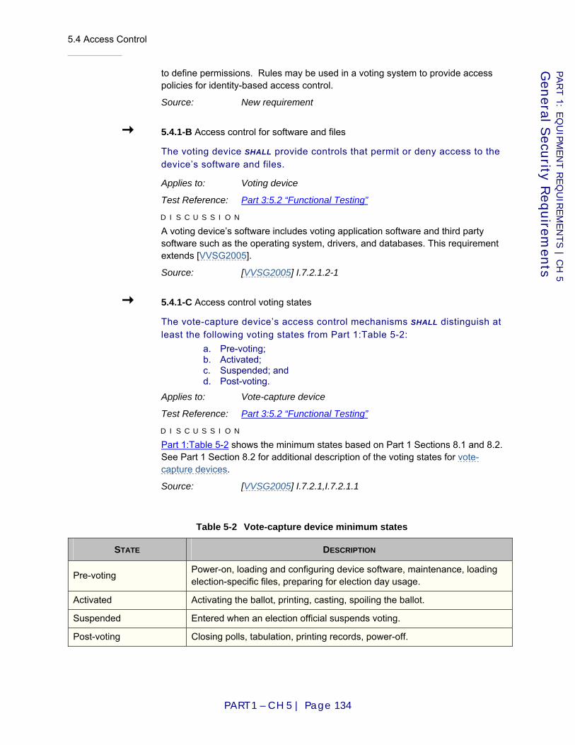
5.4 Access Control
PART 1 – CH 5 | Page 134
PART 1: E
QU
IPM
EN
T R
EQ
UIR
EM
EN
TS | C
H 5
Gen
eral Secu
rity Req
uirem
ents
to define permissions. Rules may be used in a voting system to provide access policies for identity-based access control.
Source: New requirement
5.4.1-B Access control for software and files
The voting device SHALL provide controls that permit or deny access to the device’s software and files.
Applies to: Voting device
Test Reference: Part 3:5.2 “Functional Testing”
D I S C U S S I O N
A voting device’s software includes voting application software and third party software such as the operating system, drivers, and databases. This requirement extends [VVSG2005].
Source: [VVSG2005] I.7.2.1.2-1
5.4.1-C Access control voting states
The vote-capture device’s access control mechanisms SHALL distinguish at least the following voting states from Part 1:Table 5-2:
a. Pre-voting; b. Activated; c. Suspended; and d. Post-voting.
Applies to: Vote-capture device
Test Reference: Part 3:5.2 “Functional Testing”
D I S C U S S I O N
Part 1:Table 5-2 shows the minimum states based on Part 1 Sections 8.1 and 8.2. See Part 1 Section 8.2 for additional description of the voting states for vote-capture devices.
Source: [VVSG2005] I.7.2.1,I.7.2.1.1
Table 5-2 Vote-capture device minimum states
STATE DESCRIPTION
Pre-voting Power-on, loading and configuring device software, maintenance, loading election-specific files, preparing for election day usage.
Activated Activating the ballot, printing, casting, spoiling the ballot.
Suspended Entered when an election official suspends voting.
Post-voting Closing polls, tabulation, printing records, power-off.
5.4 Access Control
PART 1 – CH 5 | Page 135
PART 1: E
QU
IPM
EN
T R
EQ
UIR
EM
EN
TS | C
H 5
Gen
eral Secu
rity Req
uirem
ents
5.4.1-D Access control state policies
The vote-capture device SHALL allow the administrator group or role to configure different access control policies available in each voting state.
Applies to: Vote-capture device
Test Reference: Part 3:5.2 “Functional Testing”
D I S C U S S I O N
Activated state should offer a strict subset of functions limited to voting only. Pre-voting and post-voting states and other defined states may be used for other functions such as defining the ballot, collecting votes, updating software, and performing other administrative and maintenance functions. For more examples, see Part 1:Table 5-3. This requirement extends [VVSG2005] I. 7.2 by establishing vote-capture device policies for each voting state in relation to access control.
Source: [VVSG2005] I.7.2.1.1
5.4.1-E Minimum permissions default
The voting device’s default access control permissions SHALL implement the minimum permissions needed for each role or group.
Applies to: Voting device
Test Reference: Part 3:5.2 “Functional Testing”
D I S C U S S I O N
Minimum permissions restrict the group or role to access only the information and resources that are necessary for its purpose. This requirement extends [VVSG2005] I. 7.2.1.1 and I.7.2.1.2 by requiring minimum default access control permissions.
Source: [VVSG2005] I.7.2.1.1, I.7.2.1.2-1
5.4.1-F Privilege escalation prevention
The voting device SHALL prevent a lower-privilege process from modifying a higher-privilege process.
Applies to: Voting device
Test Reference: Part 3:5.2 “Functional Testing”
D I S C U S S I O N
This requirement extends [VVSG2005] I.7.2.1 by preventing unauthorized process modification.
Source: [VVSG2005] I.7.2.1 and [VVSG2005] II.6.4.1
5.4.1-G Privileged operations authorization
The voting device SHALL ensure that an administrator authorizes each privileged operation.
5.4 Access Control
PART 1 – CH 5 | Page 136
PART 1: E
QU
IPM
EN
T R
EQ
UIR
EM
EN
TS | C
H 5
Gen
eral Secu
rity Req
uirem
ents
Applies to: Voting device
Test Reference: Part 3:5.2 “Functional Testing”
D I S C U S S I O N
This requirement extends [VVSG2005] I.7.2 by requiring authorization of privileged operations.
Source: [VVSG2005] I.7.2.1 and [VVSG2005] II.6.4.1
5.4.1-H Software and firmware modification prevention
The voting device SHALL prevent modification to or tampering with software or firmware through any means other than the documented procedure for software upgrade.
Applies to: Voting device
Test Reference: Part 3:5.2 “Functional Testing”
D I S C U S S I O N
This requirement is intended to ensure that there are no ways, other than the documented procedure for software upgrade, to upgrade or modify the software. This requirement aims to protect against software vulnerabilities that would allow an unauthorized individual to secretly update, modify, or tamper with the installed software. This requirement extends [VVSG2005] I.7.2 by requiring prevention of modification and tampering with software and firmware.
Source: [VVSG2005] I.7.2.1 and [VVSG2005] II.6.4.1
5.4.2 Access control identification
Identification requirements provide controls for accountability when operating and administering a voting system. Identification applies to users, applications, and processes.
5.4.2-A Access control identification
The voting device SHALL identify users, applications, and processes to which access is granted and the specific functions and data to which each entity holds authorized access.
Applies to: Voting device
Test Reference: Part 3:5.2 “Functional Testing”
D I S C U S S I O N
This requirement updates [VVSG2005] I.7.2.1.1-a by requiring that the voting device identify users, applications, and processes. It also requires that identification use either identity-based or role-based methods.
Source: [VVSG2005] I.7.2.1.1
5.4 Access Control
PART 1 – CH 5 | Page 137
PART 1: E
QU
IPM
EN
T R
EQ
UIR
EM
EN
TS | C
H 5
Gen
eral Secu
rity Req
uirem
ents
5.4.2-B Role-based access control standard
Voting devices that implement role-based access control SHALL support the recommendations for Core RBAC in the ANSI INCITS 359-2004 American National Standard for Information Technology – Role Based Access Control document.
Applies to: Voting device
Test Reference: Part 3:5.2 “Functional Testing”
D I S C U S S I O N
This requirement extends [VVSG2005] I. 7.2.1.1-a by requiring role-based methods to follow ANSI INCITS 359-2004.
Source: [VVSG2005] I.7.2.1.1
5.4.2-C Access control roles identification
The voting device SHALL identify, at a minimum, the groups or roles outlined in Part 1:Table 5-1.
Applies to: Voting device
Test Reference: Part 3:5.2 “Functional Testing”
D I S C U S S I O N
A group in a voting system is defined as a set of users, applications, or processes who share the same set of privileges and access permissions. In role-based access control methods a role serves the same purpose as a group. In identity-based access control methods groups are created, members are assigned to the groups, and permissions and privileges are applied to the group as a whole. The term groups and roles are often used interchangeably. provides example activities for each role and is not meant to include all activities performed by each role.
This requirement extends [VVSG2005] I.7.2.1.1-a by establishing minimum group or role categories. It also allows each category to apply to different voting states of operation and perform different functions.
Source: [VVSG2005] I.7.2.1.1
5.4.2-D Group member identification
The EMS SHALL individually identify the members within all groups or roles except the voting group.
Applies to: EMS
Test Reference: Part 3:4.4 “Manufacturer Practices for Quality Assurance and Configuration Management”
D I S C U S S I O N
This requirement extends [VVSG2005] I.7.2.1.1-a by requiring members of groups or roles to be identified explicitly.
Source: [VVSG2005] I.7.2.1.1
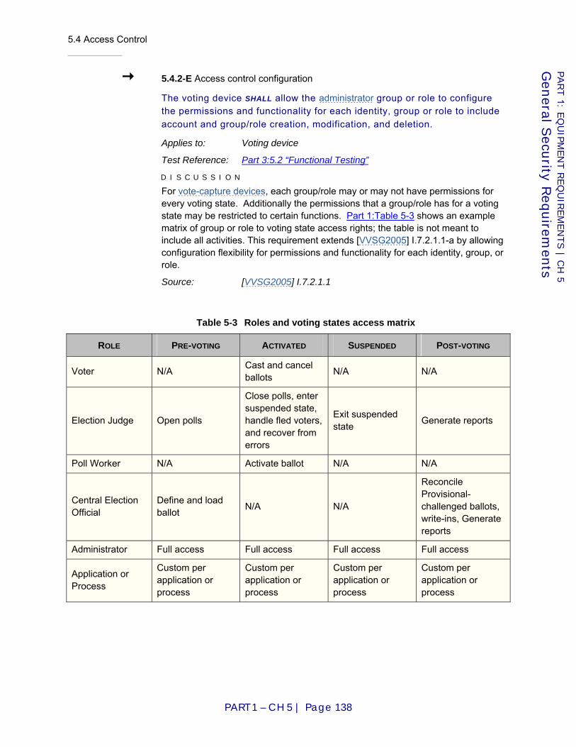
5.4 Access Control
PART 1 – CH 5 | Page 138
PART 1: E
QU
IPM
EN
T R
EQ
UIR
EM
EN
TS | C
H 5
Gen
eral Secu
rity Req
uirem
ents
5.4.2-E Access control configuration
The voting device SHALL allow the administrator group or role to configure the permissions and functionality for each identity, group or role to include account and group/role creation, modification, and deletion.
Applies to: Voting device
Test Reference: Part 3:5.2 “Functional Testing”
D I S C U S S I O N
For vote-capture devices, each group/role may or may not have permissions for every voting state. Additionally the permissions that a group/role has for a voting state may be restricted to certain functions. Part 1:Table 5-3 shows an example matrix of group or role to voting state access rights; the table is not meant to include all activities. This requirement extends [VVSG2005] I.7.2.1.1-a by allowing configuration flexibility for permissions and functionality for each identity, group, or role.
Source: [VVSG2005] I.7.2.1.1
Table 5-3 Roles and voting states access matrix
ROLE PRE-VOTING ACTIVATED SUSPENDED POST-VOTING
Voter N/A Cast and cancel ballots N/A N/A
Election Judge Open polls
Close polls, enter suspended state, handle fled voters, and recover from errors
Exit suspended state Generate reports
Poll Worker N/A Activate ballot N/A N/A
Central Election Official
Define and load ballot N/A N/A
Reconcile Provisional-challenged ballots, write-ins, Generate reports
Administrator Full access Full access Full access Full access
Application or Process
Custom per application or process
Custom per application or process
Custom per application or process
Custom per application or process

5.4 Access Control
PART 1 – CH 5 | Page 139
PART 1: E
QU
IPM
EN
T R
EQ
UIR
EM
EN
TS | C
H 5
Gen
eral Secu
rity Req
uirem
ents
5.4.3 Access control authentication
Authentication establishes the validity of the identity of the user, application, or process interacting with the voting device. Authentication is based on the identification provided by the user, application, or process interacting with the voting device. User authentication is generally classified in one of the following three categories:
(a) Something the user knows – this is usually a password, pass phrase, or PIN
(b) Something the user has – this is usually a token that may be either hardware or software based, such as a smart card
(c) Something the user is – this is usually a fingerprint, retina patter, voice pattern or other biometric data
Traditional password authentication is a single factor authentication method. A more secure method of authentication combines the various methods of authentication into two-factor authentication, or multi-factor authentication. For example, a user may use a authentication token and a passphrase for authentication. Using multi-factor provides stronger authentication than single factor. There are also cryptographic-based authentication methods such as digital signatures and challenge-response authentication, which are either software or hardware-based based tokens. Applications and processes use programmatic methods of authentication such as digital signatures and certificates.
5.4.3-A Minimum authentication mechanism
The voting device SHALL authenticate users per the minimum authentication methods outlined in Part 1:Table 5-4.
Applies to: Voting device
Test Reference: Part 3:5.2 “Functional Testing”
D I S C U S S I O N
Part 1:Table 5-4 provides the minimum authentication methods required for each group or role. Stronger authentication methods than the minimum may be used for each group or role. This requirement extends [VVSG2005] I.7.2.1.2-e by requiring a minimum level of robustness for user authentication mechanisms.
Source: [VVSG2005] I.7.2.1.2-1
5.4.3-B Multiple authentication mechanism
The voting device SHALL provide multiple authentication methods to support multi-factor authentication.
Applies to: Voting device
Test Reference: Part 3:5.2 “Functional Testing”

5.4 Access Control
PART 1 – CH 5 | Page 140
PART 1: E
QU
IPM
EN
T R
EQ
UIR
EM
EN
TS | C
H 5
Gen
eral Secu
rity Req
uirem
ents
D I S C U S S I O N
This requirement is needed to support the multi-factor authentication of the administrator group or role.
Source: [VVSG2005] I.7.2.1.2-1
5.4.3-C Administrator group or role multi-factor authentication
The voting device SHALL authenticate the administrator group or role with a multi-factor authentication mechanism.
Applies to: Voting device
Test Reference: Part 3:5.2 “Functional Testing”
D I S C U S S I O N
This requirement extends [VVSG2005] I.7.2.1.2-e by requiring multi-factor authentication for the voting device administrator group or role.
Source: [VVSG2005] I.7.2.1.2-1
Table 5-4 Minimum authentication methods for groups and roles
GROUP OR ROLE MINIMUM AUTHENTICATION METHOD
Election Judge User name and password
Poll Worker N/A – poll worker does not authenticate to voting system
Central Election Official User name and password
Administrator Two-factor authentication
Application or Process Digital certificate or signature
5.4.3-D Secure storage of authentication data
When private or secret authentication data is stored in the voting device, the data SHALL be protected to ensure that the confidentiality and integrity of the data is not violated.
Applies to: Voting device
Test Reference: Part 3:4.5 “Source Code Review”, 5.2 “Functional Testing”
D I S C U S S I O N
Ensuring the privacy and secrecy of stored data may involve the use of encryption. This requirement extends [VVSG2005] I.7.2.1.2-g by requiring securely stored private or secret authentication data.
Source: [VVSG2005] I.7.2.1.2-1

5.4 Access Control
PART 1 – CH 5 | Page 141
PART 1: E
QU
IPM
EN
T R
EQ
UIR
EM
EN
TS | C
H 5
Gen
eral Secu
rity Req
uirem
ents
5.4.3-E Setting and changing of passwords, pass phases, and keys
The voting device SHALL allow the administrator group or role to set and change passwords, pass phrases, and keys.
Applies to: Voting device
Test Reference: Part 3:5.2 “Functional Testing”
D I S C U S S I O N
This requirement support jurisdictions have different policies regarding passwords, pass phrases, and keys. This requirement extends [VVSG2005] I.7.2.1.2-e by allowing the administrator group or role flexibility in creation and modification of passwords, pass phrases, and keys.
Source: [VVSG2005] I.7.2.1.2-1
5.4.3-F Creation and disabling of privileged groups or roles
The voting device SHALL allow privileged groups or roles to be disabled and allow new individual privileged groups or roles to be created.
Applies to: Voting device
Test Reference: Part 3:5.2 “Functional Testing”
D I S C U S S I O N
Privileged accounts include any accounts within the operating system, voting device software, or other third party software with elevated privileges such as administrator, root, and maintenance accounts. This requirement extends [VVSG2005] I.7.2.1.2 by allowing the creation and disabling of privileged accounts.
Source: [VVSG2005] I.7.2.1.2-1
5.4.3-G Account lock out
The voting device SHALL lock out groups, roles, or individuals after a specified number of consecutive failed authentications attempts within a pre-defined time period.
Applies to: Voting device
Test Reference: Part 3:5.2 “Functional Testing”
D I S C U S S I O N
This requirement extends [VVSG2005] I.7.2.1.2 by requiring account lockout after a specified number of consecutive failed access attempts.
Source: [VVSG2005] I.7.2.1.2-1
5.4.3-H Account lock out configuration
The voting device SHALL allow the administrator group or role to configure the account lock out policy including the time period within which failed
5.4 Access Control
PART 1 – CH 5 | Page 142
PART 1: E
QU
IPM
EN
T R
EQ
UIR
EM
EN
TS | C
H 5
Gen
eral Secu
rity Req
uirem
ents
attempts must occur, the number of consecutive failed access attempts allowed before lock out, and the length of time the account is locked out.
Applies to: Voting device
Test Reference: Part 3:5.2 “Functional Testing”
D I S C U S S I O N
This requirement extends [VVSG2005] I.7.2.1.2 by allowing the administrator group or role flexibility in configuring the account lockout policy.
Source: [VVSG2005] I.7.2.1.2-1
5.4.3-I User name and password management
If the voting device uses a user name and password authentication method, the voting device SHALL allow the administrator to enforce password strength, histories, and expiration.
Applies to: Voting device
Test Reference: Part 3:5.2 “Functional Testing”
D I S C U S S I O N
This requirement extends [VVSG2005] I.7.2.1.2-e by requiring strong passwords, password histories, and password expiration.
Source: [VVSG2005] I.7.2.1.2-1
5.4.3-I.1 Password strength configuration
The voting device SHALL allow the administrator group or role to specify password strength for all accounts including minimum password length, use of capitalized letters, use of numeric characters, and use of non-alphanumeric characters per NIST 800-63 Electronic Authentication Guideline standards.
Applies to: Voting device
Test Reference: Part 3:5.2 “Functional Testing”
D I S C U S S I O N
This requirement extends [VVSG2005] I.7.2.1.2-e by allowing the administrator group or role flexibility in configuring password strength. It also requires the use of NIST 800-63 standards.
Source: [VVSG2005] I.7.2.1.2-1
5.4.3-I.2 Password history configuration
The voting device SHALL enforce password histories and allow the administrator to configure the history length.
Applies to: Voting device
Test Reference: Part 3:5.2 “Functional Testing”

5.4 Access Control
PART 1 – CH 5 | Page 143
PART 1: E
QU
IPM
EN
T R
EQ
UIR
EM
EN
TS | C
H 5
Gen
eral Secu
rity Req
uirem
ents
D I S C U S S I O N
Password histories are a log of previously used passwords for automatic comparison with a new chosen password. The password history is used to ensure that recently used passwords are not used again within a pre-defined number of password changes (i.e., history length). This requirement extends [VVSG2005] I.7.2.1.2-e by allowing the administrator group or role flexibility in configuring password history.
Source: [VVSG2005] I.7.2.1.2-1
5.4.3-I.3 Account information for password restriction
The voting device SHALL ensure that the username is not used in the password.
Applies to: Voting device
Test Reference: Part 3:5.2 “Functional Testing”
D I S C U S S I O N
This requirement extends [VVSG2005] I.7.2.1.2-e by restricting the use or usernames and related information in passwords.
Source: [VVSG2005] I.7.2.1.2-1
5.4.3-I.4 Automated password expiration
The voting device SHALL provide a means to automatically expire passwords in accordance with the voting jurisdiction’s policies.
Applies to: Voting device
Test Reference: Part 3:5.2 “Functional Testing”
D I S C U S S I O N
Jurisdiction policies often expire passwords after each election. This requirement extends [VVSG2005] I.7.2.1.2-e by requiring the expiration of unchanged passwords.
Source: [VVSG2005] I.7.2.1.2-1
5.4.4 Access control authorization
Authorization is the process of determining access rights based on authentication of a user, application, or process within a voting device. Authorization permits or denies access to an object by a subject. Subjects may be users, applications, or processes that interact with the voting device. Objects may be files or programs within the voting device.
5.4.4-A Account access to election data authorization
The voting device SHALL ensure that only authorized roles, groups, or individuals have access to election data.

5.4 Access Control
PART 1 – CH 5 | Page 144
PART 1: E
QU
IPM
EN
T R
EQ
UIR
EM
EN
TS | C
H 5
Gen
eral Secu
rity Req
uirem
ents
Applies to: Voting device
Test Reference: Part 3:5.2 “Functional Testing”
D I S C U S S I O N
This requirement extends [VVSG2005] I.7.2.1.2-a by restricting access to election data to authorized accounts.
Source: [VVSG2005] I.7.2.1.2-1
5.4.4-B Separation of duties
The voting device SHALL enforce separation of duty across subjects based on user identity, groups, or roles.
Applies to: Voting device
Test Reference: Part 3:5.2 “Functional Testing”
D I S C U S S I O N
This requirement extends [VVSG2005] I.7.2.1.2 by requiring separation of duty.
Source: [VVSG2005] I.7.2.1.2-1
5.4.4-C Dual person control
The voting device SHALL provide dual person control for administrative activities.
Applies to: Voting device
Test Reference: Part 3:5.2 “Functional Testing”
D I S C U S S I O N
This requirement extends [VVSG2005] I.7.2.1.2-a by requiring dual person control for administrative activities.
Source: [VVSG2005] I.7.2.1.2-1
5.4.4-D Explicit authorization
The voting device SHALL explicitly authorize subjects’ access based on access control lists or policies.
Applies to: Voting device
Test Reference: Part 3:5.2 “Functional Testing”
D I S C U S S I O N
This requirement extends [VVSG2005] I.7.2.1.2-a by requiring explicit authorization of subjects based on access control policies.
Source: [VVSG2005] I.7.2.1.2-1

5.5 System Integrity Management
PART 1 – CH 5 | Page 145
PART 1: E
QU
IPM
EN
T R
EQ
UIR
EM
EN
TS | C
H 5
Gen
eral Secu
rity Req
uirem
ents
5.4.4-E Explicit deny
The voting device SHALL explicitly deny subjects access based on access control lists or policies.
Applies to: Voting device
Test Reference: Part 3:5.2 “Functional Testing”
D I S C U S S I O N
This requirement extends [VVSG2005] I.7.2.1.2-a by requiring explicit denying of subjects access based on access control policies.
Source: [VVSG2005] I.7.2.1.2-1
5.4.4-F Authorization limits
The voting device SHALL limit the length of authorization to a specific time, time interval, or voting state.
Applies to: Voting device
Test Reference: Part 3:5.2 “Functional Testing”
D I S C U S S I O N
This requirement extends [VVSG2005] I.7.2.1.1-b by requiring limitations on authorization by time or voting state.
Source: [VVSG2005] I.7.2.1.2-1
5.5 System Integrity Management
This chapter is a guideline for securely deploying and maintaining voting system electronic devices across all system modes of voting. It is inclusive of platform security configuration including network interfaces. In many ways, security of the electronic devices is subject to the current voting system state. Perhaps more importantly, the voting system state is an indicator of who requires access to any given device. This factor significantly influences security measures.
There are some similarities between voting machines and gaming machines. As a method of assuring completeness of requirements, the Nevada Gaming Commission’s [NGC06] technical standards on gaming machines were consulted for applicability.
5.5.1 Electronic devices
Electronic device requirements are minimum safeguards for voting platforms once the platform is deployed.
5.5 System Integrity Management
PART 1 – CH 5 | Page 146
PART 1: E
QU
IPM
EN
T R
EQ
UIR
EM
EN
TS | C
H 5
Gen
eral Secu
rity Req
uirem
ents
5.5.1-A Protecting the integrity of the boot process
Before boot up or initialization, electronic devices SHALL verify the integrity of the components used to boot up or initialize the electronic device using a tamper-resistant hardware module.
Applies to: Electronic device
Test Reference: Part 3:4.5 “Source Code Review”, 5.2 “Functional Testing”
D I S C U S S I O N
A tamper-resistant hardware module, such as a trusted platform module (TPM), can be used to store the cryptographic software reference information of the components that are required to boot the electronic device. The specific types of components required for booting vary by device type, but examples of these components are boot loader files and kernel modules on a PC. The device will not boot if the files have been modified or the boot storage has been removed from the voting system. This requirement augments [VVSG2005] I.7.4.6 by explicitly requiring integrity checking of components used to boot up or initialize an electronic device.
Source: [VVSG2005] I.7.4.6-a, I.7.4.6-b, I.7.4.6-e
5.5.1-B Integrity verification of binaries before execution or memory load
Electronic devices SHALL verify the integrity of binaries (e.g., device drivers, library files, applications, and utilities) using a tamper-resistant hardware module and confirm that the binaries have been specified by the manufacturer as being required for the current voting system state before they are executed or loaded into memory.
Applies to: Electronic device
Test Reference: Part 3:4.5 “Source Code Review”, 5.2 “Functional Testing”
D I S C U S S I O N
Verifying the integrity of binaries prevents modified binaries, such as those infected with malware or inadvertently corrupted by a software or hardware failure, from being executed or loaded. A tamper-resistant hardware module, such as a trusted platform module (TPM), can be used to store the cryptographic software reference information to be used to verify integrity and voting system state specifications. Binaries that are not required for a particular state should not be executed while a device is in that state. The potential impact of permitting the binaries’ execution varies depending on the state and the nature of the binaries – examples include altering or disrupting the functionality of the system.
This requirement augments [VVSG2005] 7.4.6-b by mandating cryptographic software reference information as a mechanism for verifying the integrity of binaries, by specifying that binary integrity checking must be performed before binaries are executed or loaded into memory, and by requiring that only binaries specified as required for a particular voting system mode may be executed or loaded into memory during that mode.
Source: [VVSG2005] I.7.4.6-b
5.5 System Integrity Management
PART 1 – CH 5 | Page 147
PART 1: E
QU
IPM
EN
T R
EQ
UIR
EM
EN
TS | C
H 5
Gen
eral Secu
rity Req
uirem
ents
5.5.1-C Sandboxing applications
Electronic devices that support multi-processing architectures SHALL logically separate each application such that applications can only access resources necessary for normal functionality.
Applies to: Electronic device
Test Reference: Part 3:5.2 “Functional Testing”
D I S C U S S I O N
Logically separating applications such that only required resources can be accessed is often referred to as “sandboxing” an application. It is meant to ensure that subversion of an application’s native security will not result in access beyond normal resources.
Source: [NIST05] Security Control AC-6, SC-2
5.5.2 Removable media
While removable media is used in a number of precincts as a part of the voting process, removable media is sometimes a mechanism to propagate malicious code or exfiltrate data from electronic devices. For this reason, removable media requirements focus on enabling use of removable media, while protecting the electronic device.
5.5.2-A Restricting the use of removable media
Electronic devices SHALL disable all removable media interfaces that are not needed for each voting system state.
Applies to: Electronic device
Test Reference: Part 3:5.2 “Functional Testing”
D I S C U S S I O N
Disabling a removable media interface prevents access to removable media connected to that interface. An interface may be disabled through physical or logical means. Physically securing the removable media interface prevents the insertion and removal of removable media. Logically securing the removable media interface prevents the use of removable media inserted into the electronic device, and also prevents the removal of removable media from the electronic device (e.g., ejecting a CD or dismounting a USB flash drive). See Chapter 14: Physical Security for requirements related to physical security.
Source: [NIST05] Security Control AC-3, AC-6, MP-2
5.5.3 Backup and recovery
Backup and recovery requirements describe minimum authorization, auditing, and protective measures, without regard to specific media.
5.5 System Integrity Management
PART 1 – CH 5 | Page 148
PART 1: E
QU
IPM
EN
T R
EQ
UIR
EM
EN
TS | C
H 5
Gen
eral Secu
rity Req
uirem
ents
5.5.3-A Restricting backup and restore capabilities
Electronic devices other than EMSs SHALL NOT provide backup or restore capabilities.
Applies to: Electronic device
Test Reference: Part 3:5.2 “Functional Testing”
D I S C U S S I O N
Backup and restore capabilities introduce security holes into systems because backup operations could disrupt system functionality (e.g., locking files that the system needs to access) or give an attacker access to the system’s data, and restore operations could alter system functionality or data (e.g., replacing existing files with previous versions). Therefore, use of backup and restore capabilities should be minimized. EMSs are permitted, but are not required, to have backup and restore capabilities because of the types of information they store.
Source: [NIST05] Security Control SC-2
5.5.3-B Restricting the performance of backups and restores
EMSs that provide backup or restore capabilities SHALL only permit backup and restore operations while not in the Activated state.
Applies to: EMS
Test Reference: Part 3:5.2 “Functional Testing”
D I S C U S S I O N
Backup and restore operations should not be performed while EMSs are in the Activated state because backup operations could disrupt system functionality (e.g., locking files that the system needs to access) and restore operations could alter system functionality, vote data, etc.
Source: [NIST05] Security Control SC-2
5.5.3-C Authenticity and integrity of backup information
EMSs that perform backups SHALL create digital signatures, message authentication codes, or hashes for their backups so that their authenticity and integrity can be verified in the future.
Applies to: EMS
Test Reference: Part 3:5.2 “Functional Testing”
D I S C U S S I O N
This requirement allows EMSs to verify the authenticity and integrity of backups before restoring them.
Source: [NIST05] Security Control CP-9
5.5 System Integrity Management
PART 1 – CH 5 | Page 149
PART 1: E
QU
IPM
EN
T R
EQ
UIR
EM
EN
TS | C
H 5
Gen
eral Secu
rity Req
uirem
ents
5.5.3-D Verifying backup authenticity and integrity
EMSs that perform restores SHALL verify the authenticity and integrity of backups before restoring them.
Applies to: EMS
Test Reference: Part 3:5.2 “Functional Testing”
Source: [NIST05] Security Control CP-10
5.5.4 Malicious software protection
As described in the National Institute of Standards and Technology Special Publication 800-83 [NIST05a], malicious software, also known as malicious code and malware, refers to a program that is inserted into a system, usually covertly, with the intent of compromising the confidentiality, integrity, or availability of the victim’s data, applications, or operating system (OS) or of otherwise annoying or disrupting the victim. For a number of reasons, electronic devices associated with voting systems may be targeted by malware. Malware is inclusive of viruses, worms, Trojan horses, and malicious mobile code, as well as combinations of these, known as blended attacks. Malware also includes attacker tools such as backdoors, rootkits, and keystroke loggers. Given this understanding of malware, requirements focus on preventing occurrences of malware on electronic devices.
5.5.4-A Installing malware detection software
EMSs SHALL use malware detection software to protect themselves from common known malware that targets their operating systems, services, and applications.
Applies to: EMS
Test Reference: Part 3:5.2 “Functional Testing”
D I S C U S S I O N
Off-the-shelf malware detection software, such as antivirus software, anti-spyware software, and rootkit detection, can identify common known malware that attempts to infect an electronic device, as well as identify infections on the device. The scope of this requirement is limited to EMSs because they should have the required resources to use off-the-shelf malware detection software and also because there should be off-the-shelf malware detection software available for their platforms. For many other electronic devices, neither of these conditions is true; also, some platforms do not have common known malware threats, so malware detection software would not be useful.
This requirement augments [VVSG2005] I.7.4.2 by specifying installation of malware detection/scanning software.
Source: [VVSG2005] I.7.4.2
5.5 System Integrity Management
PART 1 – CH 5 | Page 150
PART 1: E
QU
IPM
EN
T R
EQ
UIR
EM
EN
TS | C
H 5
Gen
eral Secu
rity Req
uirem
ents
5.5.4-B Malware detection software signature updates
EMSs SHALL provide a mechanism for updating the malware detection software with newer malware signatures.
Applies to: EMS
Test Reference: Part 3:5.2 “Functional Testing”
D I S C U S S I O N
As new malware threats are discovered, particularly threats specific to voting systems, the election management’s malware detection software may need to be updated so that it can recognize and stop these threats. Many malware detection software products use the Internet by default to retrieve updates; since the use of the Internet by electronic devices is prohibited, another mechanism is needed to distribute updates, such as using a device on the local network to distribute updates, or manually distributing updates through read-only removable media. This requirement augments [VVSG2005] 7.4.2 by specifying the capability to update malware detection software with current malware signatures.
Source: [VVSG2005] I.7.4.2
5.5.4-C Scanning removable media for malware
EMSs SHALL run malware detection software against removable media to verify no common known malware is present before accepting any data from the removable media.
Applies to: EMS
Test Reference: Part 3:5.2 “Functional Testing”
D I S C U S S I O N
This prevents the introduction of common known malware onto an electronic device from removable media. This requirement augments [VVSG2005] I.7.4.2 by specifying scanning of removable media for common known malware.
Source: [VVSG2005] I.7.4.2
5.5.4-D Periodic malware scanning
EMSs SHALL be scanned for common known malware at least once every 24 hours during operation, including malware specifically targeted at voting systems.
Applies to: EMS
Test Reference: Part 3:5.2 “Functional Testing”
D I S C U S S I O N
This identifies any current infections on the electronic device caused by common known malware. This requirement augments [VVSG2005] I.7.4.2 by specifying scanning of removable media for common known malware.
Source: [VVSG2005] I.7.4.2

5.6 Communication Security
PART 1 – CH 5 | Page 151
PART 1: E
QU
IPM
EN
T R
EQ
UIR
EM
EN
TS | C
H 5
Gen
eral Secu
rity Req
uirem
ents
5.5.4-E Real-time malware scanning
EMSs SHALL perform real-time scanning for common known malware.
Applies to: EMS
Test Reference: Part 3:5.2 “Functional Testing”
D I S C U S S I O N
This prevents files infected with common known malware from being executed or otherwise loaded within the electronic device. This requirement augments [VVSG2005] I.7.4.2 by specifying real-time scanning for common known malware.
Source: [VVSG2005] I.7.4.2
5.6 Communication Security
This chapter provides requirements for communications security. The requirements address both the integrity of transmitted information and protect the voting system from communications based threats.
This chapter is organized in three parts. The first set of requirements address physical communication components including the prohibition of radio frequency (RF) capable components. The second set of requirements address data transmission security requirements related to the encoding and decoding data packets, and creating logical paths for transferring data between systems. The third set of requirements address communication security related to the voting application including the authentication of communications between voting devices.
Although voting systems can have the capability to communicate with other voting devices, there are key security concerns that must be accounted for both during voting and when election administrators prepare the voting device. This chapter does not address networking issues based on hand carried electronic media, which are addressed in the Systems Integrity Management Chapter.
5.6.1 Physical communication security
This section describes security requirements for physical communication components of voting systems including the electrical and mechanical hardware that sends and receives data.
5.6.1-A Prohibiting wireless technology
Electronic devices SHALL NOT be enabled or installed with any wireless technology (e.g., Wi-Fi, wireless broadband, Bluetooth) except for infrared technology when the signal path is shielded to prevent the escape of the signal and saturation jamming of the signal.
Applies to: Electronic device
Test Reference: Part 3:4.3 “Verification of Design Requirements”
5.6 Communication Security
PART 1 – CH 5 | Page 152
PART 1: E
QU
IPM
EN
T R
EQ
UIR
EM
EN
TS | C
H 5
Gen
eral Secu
rity Req
uirem
ents
D I S C U S S I O N
The transient and mobile properties of wireless networks are more threatening than enabling to the voting process. Wireless interfaces that are inadvertently or purposefully enabled at an electronic device are likely to leave those platforms exposed to attack and exploit, with exfiltration, manipulation, or destruction of data a possible outcome.
This requirement supersedes [VVSG2005] I.7.7 by prohibiting usage of wireless technology, except for infrared technology when the physical path is protected, in electronic voting system devices.
Source: [VVSG2005] I.7.7.1-a-h, I.7.7.2-5
5.6.1-B Restricting dependency on public communication networks
Electronic devices SHALL NOT use public communication networks (including, but not limited to the Internet and modem usage through public telephone networks), except for electronic devices at polling places that transmit unofficial end of the day results and interface with voter registration databases on election day.
Applies to: Electronic device
Test Reference: Part 3:4.3 “Verification of Design Requirements”
D I S C U S S I O N
The use of public communications networks would greatly increase the exposure of electronic devices for voting to attack and exploitation. Functions such as software patch distribution may be performed either manually or through a dedicated, standalone network that is not connected to any public communications network. The excepts to this requirement allows for end of day results to be transmitted from a polling place to a central election facility and for activation devices to connect to voter registration databases housed outside of a polling place.
This requirement supersedes [VVSG2005] I.7.6 by prohibiting usage of public communication networks for electronic voting system devices.
Source: [VVSG2005] I.7.6.1, I.7.6.2.1, I.7.6.2.2
5.6.1-B.1 Air gap for transmitting end of day results on election day
Electronic devices SHALL NOT be connected to other polling place electronic devices when transmitting end of the day results on election day.
Applies to: Electronic device
Test Reference: Part 3:4.3 “Verification of Design Requirements”
D I S C U S S I O N
This requirement is to provide an air gap between electronic devices networked at the polling place and electronic devices that connect externally from the polling place. This requirement allows for end of day results to be transmitted from a polling place to a central election facility.
5.6 Communication Security
PART 1 – CH 5 | Page 153
PART 1: E
QU
IPM
EN
T R
EQ
UIR
EM
EN
TS | C
H 5
Gen
eral Secu
rity Req
uirem
ents
Source: New requirement
5.6.1-B.2 Air gap for connecting to voter registration databases
Electronic devices that connect to voter registration databases outside a polling place on election day SHALL never be connected to other polling place electronic devices.
Applies to: Electronic device
Test Reference: Part 3:4.3 “Verification of Design Requirements”
D I S C U S S I O N
This requirement is to provide an air gap between electronic devices networked at the polling place and electronic devices that connect externally from the polling place. This requirement allows for activation devices to connect to voter registration databases housed externally from the polling place, but the activation devices cannot be connected to other polling place electronic devices.
Source: New requirement
5.6.1-C Limiting network interfaces based on voting state
Electronic devices SHALL have the ability to enable or disable physical network interfaces (including modems) based upon the voting system state.
Applies to: Electronic device
Test Reference: Part 3:5.2 “Functional Testing”
D I S C U S S I O N
Making an electronic device accessible on a network significantly increases the risk of that device to attack and exploitation. Election Officials need the ability to enable a physical network interface for use during a particular voting system state and to disable other network interfaces that are not required during that state. This reduces the exposure of the electronic devices to network-based attacks.
Source: [NIST05] Security Control AC-6
5.6.1-D Preventing traffic from passing through EMSs
EMSs with multiple active network interfaces (including modems) SHALL NOT act as bridges or routers between networks that permit network traffic to pass through the electronic management systems.
Applies to: Electronic device
Test Reference: Part 3:5.2 “Functional Testing”
D I S C U S S I O N
Allowing network traffic to pass through a device that is not specifically designed to be part of the network/security infrastructure provides a possible method for malicious traffic to circumvent network security controls.
Source: [NIST05] Security Control AC-6

5.6 Communication Security
PART 1 – CH 5 | Page 154
PART 1: E
QU
IPM
EN
T R
EQ
UIR
EM
EN
TS | C
H 5
Gen
eral Secu
rity Req
uirem
ents
5.6.1-E Implementing unique network identification
Each electronic device SHALL have a unique physical address/identifier for each network interface.
Applies to: Electronic device
Test Reference: Part 3:4.3 “Verification of Design Requirements”
D I S C U S S I O N
Most networking protocols require a unique physical address or other identifier for each network interface so that each network interface attached to a particular network can be uniquely identified. For example, Ethernet requires that each network interface have a unique media access code (MAC) address. Having such an identifier for each network interface is also beneficial for security because it permits each electronic device on a network to be uniquely identified.
Source: [NIST05] Security Control IA-3
5.6.2 Data transmission security
This section describes security requirements related to the encoding and decoding of data packets, and creating logical paths for transferring date between voting systems.
5.6.2-A Documenting network processes and applications
The manufacturer SHALL provide a listing of all network communication processes and applications required for the electronic device to function properly.
Applies to: Electronic device
Test Reference: Part 3:4.1 “Initial Review of Documentation”
D I S C U S S I O N
Understanding required network processes and applications is necessary for understanding the attack exposure of any given electronic device.
This requirement generalizes [VVSG2005] I.7.5.2-b, which requires that manufacturers document all COTS hardware, and software communication devices used in the development and/or operation of the voting system if those devices are used on public communications networks. This requirement requires manufacturers to list network communication processes and applications required for the election system to function properly. There are no guidelines in the [VVSG2005] that require documentation of devices used for local networking.
This requirement augments [VVSG2005] I.7.5.1-b-ii by mandating documentation of valid processes and applications associated with network ports and protocols.
Source: [VVSG2005] I.7.5.1-b, I.7.5.2-b

5.6 Communication Security
PART 1 – CH 5 | Page 155
PART 1: E
QU
IPM
EN
T R
EQ
UIR
EM
EN
TS | C
H 5
Gen
eral Secu
rity Req
uirem
ents
5.6.2-B Prohibiting unnecessary communication between electronic devices
Electronic devices SHALL prohibit intercommunications between electronic devices except where required for normal function.
Applies to: Electronic device
Test Reference: Part 3:5.2 “Functional Testing”
D I S C U S S I O N
In the interest of reducing the number of nodes accessing a given platform and potentially the voting data thereof, devices that have no need to interact over the network would be locally prohibited from those interactions. This reduces possible sources of network attack.
Source: [NIST05] Security Control AC-6
5.6.2-C Implementing integrity of data in transit
Electronic devices SHALL provide integrity protection for data in transit through generation of integrity data (digital signatures or message authentication codes) for outbound traffic and verification of the integrity data for inbound traffic.
Applies to: Electronic device
Test Reference: Part 3:4.5 “Source Code Review”, 5.2 “Functional Testing”
D I S C U S S I O N
Integrity protection ensures that any inadvertent or intentional alterations to data are detected by the recipient. Integrity protection for data in transit may be provided through the use of various protocols, such as IPsec VPNs and SSL/TLS.
This requirement modifies [VVSG2005] I.7.5.1, which requires use of error correcting or detecting codes, by mandating use digital signatures or message authentication codes for data integrity. These provide addition protection against threats than error detecting codes, but do not offer data correcting capabilities.
This requirement modifies [VVSG2005] I.7.5.1-a by specifying the use of cryptographic checksums (digital signatures and hashes) to be used to ensure information integrity in transit.
This requirement modifies [VVSG2005] I.7.6.1, which requires the use of digital signatures in communications over a public network between a voter server and another device. This requirement extends [VVSG2005] I.7.6.1 by requiring integrity data for all data in transit. It furthermore includes a requirement to verify the integrity data for inbound data.
This requirement extends [VVSG2005] 7.7.3-a, which requires protection against data manipulation on wireless communications, by requiring this protection on all data transmissions. Note that this document contains a prohibition against use of most wireless technology.
Source: [VVSG2005] I.7.5.1-a, I.7.6.1, I.7.7.3
5.6 Communication Security
PART 1 – CH 5 | Page 156
PART 1: E
QU
IPM
EN
T R
EQ
UIR
EM
EN
TS | C
H 5
Gen
eral Secu
rity Req
uirem
ents
5.6.3 Application communication security
This section describes security requirements related to the communications of the voting application.
5.6.3-A Implementing unique system identifiers
Each electronic device SHALL have a unique system identifier (ID).
Applies to: Electronic device
Test Reference: Part 3:5.2 “Functional Testing”
D I S C U S S I O N
System ID can be in the form of a unique system or device roles that can be used as a mechanism to filter the type of packets that are allowed or dropped by the device.
Source: [NIST05] Security Control IA-3
5.6.3-B Prohibiting unauthenticated communications
Electronic devices SHALL mutually authenticate using the devices’ unique system IDs before any additional network data packets are processed.
Applies to: Electronic device
Test Reference: Part 3:4.5 “Source Code Review”, 5.2 “Functional Testing”
D I S C U S S I O N
Mutual authentication provides assurance that each electronic device is legitimate. Mutual authentication can be performed using various protocols, such as IPsec and SSL/TLS.
Source: [NIST05] Security Control IA-3
5.6.3-C Limiting network ports and shares and associated network services and
protocols
Electronic devices SHALL have only the network ports and shares active and network services and protocols enabled as specified in Requirement 1.2.3-D.
Applies to: Electronic device
Test Reference: Part 3:5.2 “Functional Testing”
D I S C U S S I O N
Limiting network ports and shares and associated network services and protocols reduces the “attack surface” of the electronic devices. Attackers will have a diminishing chance of successful remote attack with each network port, share, service, and protocol that is disabled.
Source: [NIST05] Security Control AC-6
5.6 Communication Security
PART 1 – CH 5 | Page 157
PART 1: E
QU
IPM
EN
T R
EQ
UIR
EM
EN
TS | C
H 5
Gen
eral Secu
rity Req
uirem
ents
5.6.3-D Documenting network ports and shares and associated network services
and protocols
The manufacturer SHALL document all network ports, shares, services, and protocols required for the electronic device to function properly.
Applies to: Electronic device
Test Reference: Part 1:4.1 “Overview”
D I S C U S S I O N
Understanding required network ports, shares (both visible and hidden/administrative), services, and protocols is necessary for understanding the attack exposure of any given electronic device. Based on local risk decisions, election officials will utilize the listing of required network ports, shares, services, and protocols to adjust configuration of an electronic device and the corresponding attack exposure.
Source: [NIST05] Security Control AC-6
5.6.3-E Documenting information available to devices
The manufacturer SHALL define the minimum amount of information requested from unauthenticated devices via active network ports and shares.
Applies to: Electronic device
Test Reference: Part 1:4.1 “Overview” as part of Requirement Part 1:5.6.3-F
D I S C U S S I O N
This requirement is meant to document the minimum amount and depth of information available to malicious network entities accessing the electronic device remotely. Information available through banners, help functions, and direct interaction with available ports and shares often gives remote attackers illuminating information about the electronic device. Armed with this expanded information, an attacker can evolve their attack to a more educated and specific effort, increasing probability of a successful attack.
Source: [SCAM01]
5.6.3-F Minimizing information available to devices
Electronic devices SHALL request no more information than required to unauthenticated devices via active network ports and shares.
Applies to: Electronic device
Test Reference: Part 3:5.2 “Functional Testing”
D I S C U S S I O N
This requirement is meant to minimize the amount and depth of information available to malicious network entities accessing the electronic device remotely. Information available through banners, help functions, and direct interaction with
5.6 Communication Security
PART 1 – CH 5 | Page 158
PART 1: E
QU
IPM
EN
T R
EQ
UIR
EM
EN
TS | C
H 5
Gen
eral Secu
rity Req
uirem
ents
available ports and shares often gives remote attackers illuminating information about the electronic device. Armed with this expanded information, an attacker can evolve their attack to a more educated and specific effort, increasing probability of a successful attack.
Source: [SCAM01]
5.6.3-G Monitoring of host and network communication for attack and policy
compliance
Electronic devices SHALL monitor inbound and outbound network communication for evidence of attack and security usage non-compliance.
Applies to: Electronic device
Test Reference: Part 3:5.2 “Functional Testing”
D I S C U S S I O N
Security usage non-compliance refers to instances where electronic device users are disobeying local policy.
See NIST Special Publication 800-94 – Guide to Intrusion Detection and Prevention Systems [NIST07] for more information on host and network communication monitoring and attack prevention.
This requirement extends [VVSG2005] I.7.5.1-b and I.7.5.2-a by requiring that intrusion detection systems monitor all inbound and outbound network connections, while [VVSG2005] 7.5.1-b and 7.5.2-a only require such systems monitor public communications network connections.
Source: [NIST05] Security Control S-I-4, S-I-10, I.7.5.1-b, I.7.5.2-a
5.6.3-H Prevention of host and network communication based attacks
Electronic devices SHALL provide the capability to stop inbound and outbound network attacks.
Applies to: Electronic device
Test Reference: Part 3:5.2 “Functional Testing”
D I S C U S S I O N
See NIST Special Publication 800-94 – Guide to Intrusion Detection and Prevention Systems [NIST07] for more information on host and network communication monitoring and attack prevention.
This requirement generalizes [VVSG2005] I.7.5.2-c, which describes the required capabilities of a voting device to stop an incoming attack over a network connection. This requirement further extends [VVSG2005] 7.5.2-c by requiring the ability to stop outgoing attacks as well.
Source: [NIST05] Security Control S-I-4, S-I-10, I.7.5.2-c

5.7 System Event Logging
PART 1 – CH 5 | Page 159
PART 1: E
QU
IPM
EN
T R
EQ
UIR
EM
EN
TS | C
H 5
Gen
eral Secu
rity Req
uirem
ents
5.7 System Event Logging
An event is something that occurs within a voting device and a log is a record of these events that have occurred. Each log entry contains information related to a specific event. Logs are used for error reporting, auditing, troubleshooting problems, optimizing performance, recording the actions of users, and providing data useful for investigating malicious activity.
Event logs are typically divided into two categories: system events and audit records. System events are operational actions performed by voting device components, such as shutting down the voting device, starting a service, usage information, client requests, and other information. Audit records contain security event information such as successful and failed authentication attempts, file accesses, and security policy changes. Other applications and third party software, such as antivirus software and intrusion detection software also record audit logs. For the purpose of this chapter system event logging will be used to include both system and audit logs for voting devices. System event logs are of equal importance in the output of an election as the electronic CVRs and vote totals.
This chapter describes voting device capabilities that perform system event logging to assist in voting device troubleshooting, recording a history of voting device activity, and detecting unauthorized or malicious activity. It also describes the use of log management to protect the confidentiality and integrity of logs while also ensuring their availability. The voting device software, operating system, and/or applications may perform the actual system event logging. There may be multiple logs in use on a single device.
The requirements in this section protect against the following intermediate attack goals:
♦ The ability of an attacker to undetectably alter the logs;
♦ The ability of an attacker to remove an entry from the log; and
♦ The ability of an attacker to create an entry in the log.
This section defines the event logging requirements for voting devices. It outlines the various measures that the manufacturers and the voting device shall provide to ensure the functionality, performance, and security of the voting device event logging. These recommendations apply to the full scope of voting device functionality, including voting, pre- and post-voting activities, and maintenance of the voting device.
5.7.1 General system event logging
General requirements address the high-level functionality of a voting (programmed) device. These are the fundamental event logging requirements upon which other requirements in this section are based.

5.7 System Event Logging
PART 1 – CH 5 | Page 160
PART 1: E
QU
IPM
EN
T R
EQ
UIR
EM
EN
TS | C
H 5
Gen
eral Secu
rity Req
uirem
ents
5.7.1-A Event logging mechanisms requirement
The voting device SHALL provide event logging mechanisms designed to record voting device activities.
Applies to: Programmed device
Test Reference: Part 3:4.3 “Verification of Design Requirements”
D I S C U S S I O N
This requirement generalizes [VVSG2005] I.2.1.5.1, which provides a basic description of required event logging functionality.
Source: [VVSG2005] I.2.1.5.1
5.7.1-B Integrity protection requirement
The voting device SHALL enable file integrity protection for stored log files as part of the default configuration.
Applies to: Programmed device
Test Reference: Part 3:4.4 “Manufacturer Practices for Quality Assurance and Configuration Management”, 4.5 “Source Code Review”
D I S C U S S I O N
File integrity protection includes techniques such as a digital signature that would alert to data modification and tampering.
This requirement clarifies [VVSG2005] I.2.1.5.1-a-v, which requires that that the integrity of log files be maintained, by more specifically requiring that log files have integrity protection in their default configuration.
Source: [VVSG2005] I.2.1.5.1-a
5.7.1-C Voter privacy and ballot secrecy requirement
The voting device logs SHALL NOT contain information that, if published, would violate ballot secrecy or voter privacy or that would compromise voting system security in any way.
Applies to: Programmed device
Test Reference: Part 3:4.5 “Source Code Review”, 5.2 “Functional Testing”
D I S C U S S I O N
The device must be constructed so that the security of the system does not rely upon the secrecy of the event logs. It should be considered routine for event logs to be made available to election officials and possibly even to the public, if election officials so desire. The system must be designed to permit the election officials to do so without fear of negative consequences to the security and integrity of the election. For example, cryptographic secret keys or passwords must not be logged in event log records.
Source: [VVSG2005] I.5.4
5.7 System Event Logging
PART 1 – CH 5 | Page 161
PART 1: E
QU
IPM
EN
T R
EQ
UIR
EM
EN
TS | C
H 5
Gen
eral Secu
rity Req
uirem
ents
5.7.1-D Event characteristics logging requirement
The voting device SHALL log at a minimum the following data characteristics for each type of event:
a. System ID; b. Unique event ID and/or type; c. Timestamp; d. Success or failure of event, if applicable; e. User ID triggering the event, if applicable; f. Resources requested, if applicable.
Applies to: Programmed device
Test Reference: Part 3:5.2 “Functional Testing”
D I S C U S S I O N
This requirement clarifies and extends [VVSG2005] I.2.1.5.1-a and I.2.1.5.1-b by describing the required information that must be included with each event in the event log. [VVSG2005] 2.1.5.1-b is a requirement that discusses error messages and states that error messages must be logged. This document does not, in general, treat logging error messages differently than logging other events.
Source: [VVSG2005] I.2.1.5.1-a, I.2.1.5.1-b
5.7.1-D.1 Timekeeping requirement
Timekeeping mechanisms SHALL generate time and date values.
Applies to: Programmed device
Test Reference: Part 3:5.2 “Functional Testing”
D I S C U S S I O N
This requirement generalizes [VVSG2005] I.2.1.5.1-a-ii, which requires the inclusion of a real-time clock in the hardware of voting systems.
Source: [VVSG2005] I.2.1.5.1-a
5.7.1-D.2 Time precision requirement
The precision of the timekeeping mechanism SHALL be able to distinguish and properly order all audit records.
Applies to: Programmed device
Test Reference: Part 3:5.2 “Functional Testing”
D I S C U S S I O N
This requirement extends [VVSG2005] I.2.1.5.1-a by explicitly requiring that the timekeeping mechanism used to stamp audit records be precise enough to distinguish and properly order all events logged.
Source: [VVSG2005] I.2.1.5.1-a
5.7 System Event Logging
PART 1 – CH 5 | Page 162
PART 1: E
QU
IPM
EN
T R
EQ
UIR
EM
EN
TS | C
H 5
Gen
eral Secu
rity Req
uirem
ents
5.7.1-D.3 Timestamp data requirement
Timestamps SHALL include date and time, including hours, minutes, and seconds.
Applies to: Programmed device
Test Reference: Part 3:5.2 “Functional Testing”
D I S C U S S I O N
Even if the accuracy of the clock leaves something to be desired, the seconds are useful to discern burst and gaps in the event stream.
This requirement clarifies [VVSG2005] I.2.1.5.1-a by explicitly requiring that the date, hour, minute and second be recorded for each audit record timestamp.
Source: [VVSG2005] I.2.1.5.1-a
5.7.1-D.4 Timestamp compliance requirement
Timestamps SHALL comply with ISO 8601 and provide all four digits of the year and include the time zone.
Applies to: Programmed device
Test Reference: Part 3:5.2 “Functional Testing”
D I S C U S S I O N
This requirement extends [VVSG2005] 2.1.5.1-a by requiring that timestamps comply with the ISO 8601 standard and include the time zone. The [VVSG2005] requires a timestamp, but does not specify a format.
Source: [VVSG2005] I.2.1.5.1-a
5.7.1-D.5 Clock set requirement
Voting devices SHALL only allow administrators to set the clock.
Applies to: Programmed device
Test Reference: Part 3:5.2 “Functional Testing”
D I S C U S S I O N
This requirement is needed to adjust clocks for each election. Since a voting system architecture may not support complete access control capabilities due to resource constraints, this requirement may or may apply. For example, a voting system architecture may only support a single identity, group, or role, so the ability to distinguish administrators from other users may not possible. However, when the voting system architecture has the capability to distinguish administrators from other users, the requirement must be satisfied.
Source: [VVSG2005] I.5.4
5.7 System Event Logging
PART 1 – CH 5 | Page 163
PART 1: E
QU
IPM
EN
T R
EQ
UIR
EM
EN
TS | C
H 5
Gen
eral Secu
rity Req
uirem
ents
5.7.1-D.6 Clock drift minimum requirement
The voting device SHALL limit clock drift to a minimum of 1 minute within a 15 hour period after the clock is set.
Applies to: Programmed device
Test Reference: Part 3:5.2 “Functional Testing”
D I S C U S S I O N
The accuracy of the timekeeping mechanism relative to UTC (Coordinated Universal Time) may depend on application of a manufacturer-specified clock set procedure. NIST and USNO time references are far more accurate, and higher accuracy is desirable, but many clock mechanism exhibit significant drift due to temperature, etc. and simple correction methods for a fast local clock might violate the monotonic time requirement.
Source: [VVSG2005] I.5.4
5.7.1-E Minimum event logging requirement
The voting device SHALL log at a minimum the system events described in Part 1:Table 5-5.
Applies to: Programmed device
Test Reference: Part 3:5.2 “Functional Testing”
D I S C U S S I O N
Part 1:Table 5-5 presents a minimum list of system events to be logged. The table also includes an “applies to” reference specifying the class of devices that are subject to each requirement.
This requirement clarifies and extends [VVSG2005] I.5.4.1, I.5.4.2, and I.5.4.3 by specifying a list of system events that must trigger an event log record. [VVSG2005] I.5.4.1 discusses required event log records for pre-election events. [VVSG2005] I.5.4.2 discusses required event log records for system readiness. [VVSG2005] I.5.4.3 discusses required event log records during the operation of diagnostic routines and the casting and tallying of ballots.
Source: [VVSG2005] I.5.4.1, I.5.4.2-a, I.5.4.3-a
5.7.1-E.1 Minimum logging disabling requirement
The voting device SHALL ensure that the minimum event logging in Part 1:Table 5-5 cannot be disabled.
Applies to: Programmed device
Test Reference: Part 3:5.2 “Functional Testing”
Source: [VVSG2005] I.5.4
Table 5-5 Minimum events to log
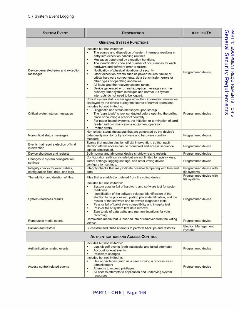
5.7 System Event Logging
PART 1 – CH 5 | Page 164
PART 1: E
QU
IPM
EN
T R
EQ
UIR
EM
EN
TS | C
H 5
Gen
eral Secu
rity Req
uirem
ents
SYSTEM EVENT DESCRIPTION APPLIES TO
GENERAL SYSTEM FUNCTIONS
Device generated error and exception messages
Includes but not limited to: The source and disposition of system interrupts resulting in
entry into exception handling routines. Messages generated by exception handlers. The identification code and number of occurrences for each
hardware and software error or failure. Notification of physical violations of security. Other exception events such as power failures, failure of
critical hardware components, data transmission errors or other types of operating anomalies.
All faults and the recovery actions taken. Device generated error and exception messages such as
ordinary timer system interrupts and normal I/O system interrupts do not need to be logged.
Programmed device
Critical system status messages
Critical system status messages other than information messages displayed by the device during the course of normal operations. Includes but not limited to: Diagnostic and status messages upon startup The “zero totals” check conducted before opening the polling
place or counting a precinct centrally For paper-based systems, the initiation or termination of card
reader and communications equipment operation Printer errors
Programmed device
Non-critical status messages Non-critical status messages that are generated by the device’s data quality monitor or by software and hardware condition monitors.
Programmed device
Events that require election official intervention
Events that require election official intervention, so that each election official access can be monitored and access sequence can be constructed.
Programmed device
Device shutdown and restarts Both normal and abnormal device shutdowns and restarts. Programmed device
Changes to system configuration settings
Configuration settings include but are not limited to registry keys, kernel settings, logging settings, and other voting device configuration settings.
Programmed device
Integrity checks for executables, configuration files, data, and logs.
Integrity checks that may indicate possible tampering with files and data.
Programmed device with file systems
The addition and deletion of files. Files that are added or deleted from the voting device. Programmed device with file systems
System readiness results
Includes but not limited to: System pass or fail of hardware and software test for system
readiness Identification of the software release, identification of the
election to be processed, polling place identification, and the results of the software and hardware diagnostic tests
Pass or fail of ballot style compatibility and integrity test Pass or fail of system test data removal Zero totals of data paths and memory locations for vote
recording
Programmed device
Removable media events Removable media that is inserted into or removed from the voting device. Programmed device
Backup and restore Successful and failed attempts to perform backups and restores. Election Management Systems
AUTHENTICATION AND ACCESS CONTROL
Authentication related events
Includes but not limited to: Login/logoff events (both successful and failed attempts) Account lockout events Password changes
Programmed device
Access control related events
Includes but not limited to: Use of privileges (such as a user running a process as an
administrator) Attempts to exceed privileges All access attempts to application and underlying system
resources
Programmed device
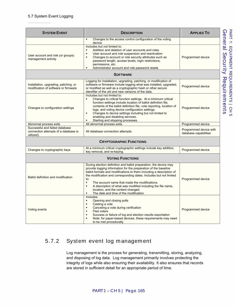
5.7 System Event Logging
PART 1 – CH 5 | Page 165
PART 1: E
QU
IPM
EN
T R
EQ
UIR
EM
EN
TS | C
H 5
Gen
eral Secu
rity Req
uirem
ents
SYSTEM EVENT DESCRIPTION APPLIES TO Changes to the access control configuration of the voting
device
User account and role (or groups) management activity
Includes but not limited to: Addition and deletion of user accounts and roles User account and role suspension and reactivation Changes to account or role security attributes such as
password length, access levels, login restrictions, permissions, etc.
Administrator account and role password resets
Programmed device
SOFTWARE
Installation, upgrading, patching, or modification of software or firmware
Logging for installation, upgrading, patching, or modification of software or firmware include logging what was installed, upgraded, or modified as well as a cryptographic hash or other secure identifier of the old and new versions of the data.
Programmed device
Changes to configuration settings
Includes but not limited to: Changes to critical function settings. At a minimum critical
function settings include location of ballot definition file, contents of the ballot definition file, vote reporting, location of logs, and voting device configuration settings.
Changes to device settings including but not limited to enabling and disabling services.
Starting and stopping processes.
Programmed device
Abnormal process exits All abnormal process exits. Programmed device Successful and failed database connection attempts (if a database is utilized).
All database connection attempts. Programmed device with database capabilities
CRYPTOGRAPHIC FUNCTIONS
Changes to cryptographic keys At a minimum critical cryptographic settings include key addition, key removal, and re-keying. Programmed device
VOTING FUNCTIONS
Ballot definition and modification
During election definition and ballot preparation, the device may provide logging information for the preparation of the baseline ballot formats and modifications to them including a description of the modification and corresponding dates. Includes but not limited to: The account name that made the modifications. A description of what was modified including the file name,
location, and the content changed. The date and time of the modification.
Programmed device
Voting events
Includes: Opening and closing polls Casting a vote Canceling a vote during verification Fled voters Success or failure of log and election results exportation Note: for paper-based devices, these requirements may need
to be met procedurally
Programmed device
5.7.2 System event log management
Log management is the process for generating, transmitting, storing, analyzing, and disposing of log data. Log management primarily involves protecting the integrity of logs while also ensuring their availability. It also ensures that records are stored in sufficient detail for an appropriate period of time.

5.7 System Event Logging
PART 1 – CH 5 | Page 166
PART 1: E
QU
IPM
EN
T R
EQ
UIR
EM
EN
TS | C
H 5
Gen
eral Secu
rity Req
uirem
ents
A log management infrastructure consists of the hardware, software, networks, and media used to generate, transmit, store, and analyze log data. The events outlined in this section may be logged as part of the underlying operating system, the voting device software, or other third party applications.
5.7.2-A Default logging policy requirement
The voting device SHALL implement default settings for secure log management activities, including log generation, transmission, storage, analysis, and disposal.
Applies to: Voting device
Test Reference: Part 3:4.1 “Initial Review of Documentation”
Source: [VVSG2005] I.5.4
5.7.2-B Reporting log failures, clearing, and rotation requirement
The voting device SHALL log logging failures, log clearing, and log rotation.
Applies to: Programmed device
Test Reference: Part 3:5.2 “Functional Testing”
D I S C U S S I O N
A secondary logging mechanism may be used to log failures, clearing, and rotation.
Source: [VVSG2005] I.5.4
5.7.2-C Log format requirement
The voting device SHALL store logs in a publicly documented log format, such as XML, or include a utility to export the logs into a publicly documented format for offline viewing.
Applies to: Programmed device
Test Reference: Part 3:4.3 “Verification of Design Requirements”
D I S C U S S I O N
In some cases, election officials may be required to or may choose to disclose event logs in electronic form to investigators, candidates, observers, or to the public. The voting device must be designed to permit recipients of the event logs to understand and interpret the contents of the event logs and to write their own software tools to parse and analyze those event logs.
Source: [VVSG2005] I.5.4
5.7.2-D Event log free space requirement
The manufacturer SHALL ensure that the voting device is supplied with enough free storage to include several maximum size event logs.
Applies to: Programmed device
5.7 System Event Logging
PART 1 – CH 5 | Page 167
PART 1: E
QU
IPM
EN
T R
EQ
UIR
EM
EN
TS | C
H 5
Gen
eral Secu
rity Req
uirem
ents
Test Reference: Part 3:5.2 “Functional Testing”
D I S C U S S I O N
The manufacturer should declare an upper limit on how much storage an event log might require during an election, referred to as the maximum size event log.
Source: [VVSG2005] I.5.4
5.7.2-E Event log retention capability requirement
The voting device SHALL be capable of retaining the event log data from previous elections.
Applies to: Programmed device
Test Reference: Part 3:5.2 “Functional Testing”
D I S C U S S I O N
In practice, previous event logs are typically cleared prior to the start of a new election. In some cases, jurisdictions may want to maintain previous event logs on the voting device. Event log data may be retained according to various methods including log file size, log entry counts, and time settings.
Source: [VVSG2005] I.5.4
5.7.2-F Log retention settings capability requirement
The voting device SHALL only allow administrators to modify the log data retention settings including the actions to take when a log reaches its maximum retention such as overwriting logs, rotating logs, or halting logging.
Applies to: Programmed device
Test Reference: Part 3:5.2 “Functional Testing”
D I S C U S S I O N
Many event logs have a maximum size for storage, such as storing the 10,000 most recent events, or keeping 100MB of log data. When the log storage capacity is reached, the log may overwrite old data with new data or stop logging altogether. Since a voting system architecture may not support complete access control capabilities due to resource constraints, this requirement may or may apply. For example, a voting system architecture may only support a single identity, group, or role, so the ability to distinguish administrators from other users may not possible. However, when the voting system architecture has the capability to distinguish administrators from other users, the requirement must be satisfied.
Source: [VVSG2005] I.5.4
5.7.2-G Log rotation capability requirement
The voting device SHALL be capable of rotating the event log data to manage log file growth.
Applies to: Programmed device

5.7 System Event Logging
PART 1 – CH 5 | Page 168
PART 1: E
QU
IPM
EN
T R
EQ
UIR
EM
EN
TS | C
H 5
Gen
eral Secu
rity Req
uirem
ents
Test Reference: Part 3:5.2 “Functional Testing”
D I S C U S S I O N
Log file rotation may involve regular (e.g., hourly, nightly, or weekly) moving of an existing log file to some other file name and/or location and starting fresh with an empty log file. Jurisdictions should ensure that the log rotation procedure includes a labeling method to identify the type of log, the system that created the logs, and the date of the logs.
Source: [VVSG2005] I.5.4
5.7.2-H Event log deletion capability requirement
The voting device SHALL be capable of only allowing the administrator to delete previous event logs prior to starting a new election.
Applies to: Programmed device
Test Reference: Part 3:5.2 “Functional Testing”
D I S C U S S I O N
Since a voting system architecture may not support complete access control capabilities due to resource constraints, this requirement may or may not apply. For example, a voting system architecture may only support a single identity, group, or role, so the ability to distinguish administrators from other users may not possible. However, when the voting system architecture has the capability to distinguish administrators from other users, the requirement must be satisfied.
Source: [VVSG2005] I.5.4
5.7.2-I Event log access requirement
The voting device SHALL restrict event log access to write or append-only for privileged logging processes and read-only for administrator accounts or roles.
Applies to: Programmed device
Test Reference: Part 3:5.2 “Functional Testing”
D I S C U S S I O N
Certain applications and processes need write and/or append access to system event logs in order to create entries. Administrator accounts or roles need read access for log analysis and other log management activities. Since a voting system architecture may not support complete access control capabilities due to resource constraints, this requirement may or may apply. For example, a voting system architecture may only support a single identity, group, or role, so the ability to distinguish administrators from other users may not possible. However, when the voting system architecture has the capability to distinguish administrators from other users, the requirement must be satisfied.
Source: [VVSG2005] I.5.4

5.7 System Event Logging
PART 1 – CH 5 | Page 169
PART 1: E
QU
IPM
EN
T R
EQ
UIR
EM
EN
TS | C
H 5
Gen
eral Secu
rity Req
uirem
ents
5.7.2-J Event log separation requirement
The voting device SHALL ensure that each election’s event logs and each device’s event logs are separable from each other.
Applies to: Programmed device
Test Reference: Part 3:5.2 “Functional Testing”
Source: [VVSG2005] I.5.4
5.7.2-K Event log export requirement
The voting device SHALL digitally sign and export event logs at the end of an election, along with all other election results from the device.
Applies to: Programmed device
Test Reference: Part 3:5.2 “Functional Testing”
Source: [VVSG2005] I.5.4
5.7.2-L Log viewing and analysis requirement
The voting device SHALL include an application or program to view, analyze, and search event logs.
Applies to: Programmed device
Test Reference: Part 3:5.2 “Functional Testing”
Source: [VVSG2005] I.5.4
5.7.2-M Event logging malfunction requirement
The voting device SHALL halt voting activities and create an alert if the logging system malfunctions or is disabled.
Applies to: Programmed device
Test Reference: Part 3:5.2 “Functional Testing”
Source: [VVSG2005] I.5.4
5.7.2-N Log file capacity requirement
The voting device SHALL create an alert at user-defined intervals as the logs begin to fill.
Applies to: Programmed device
Test Reference: Part 3:5.2 “Functional Testing”
D I S C U S S I O N
User defined intervals for system event log capacity may include alerting when logs are 50%, 75%, and 95% full.
Source: [VVSG2005] I.5.4

5.7 System Event Logging
PART 1 – CH 5 | Page 170
PART 1: E
QU
IPM
EN
T R
EQ
UIR
EM
EN
TS | C
H 5
Gen
eral Secu
rity Req
uirem
ents
5.7.2-O Event logging suspension requirement
The voting device SHALL suspend voting if the logs fill to a pre-defined capacity.
Applies to: Programmed device
Test Reference: Part 3:5.2 “Functional Testing”
Source: [VVSG2005] I.5.4
5.7.3 System event log protection
Because logs contain voting device event records, they need to be protected from breaches of their integrity and availability. Logs that are secured improperly in storage or in transit might also be susceptible to intentional and unintentional alteration and destruction. This could cause a variety of impacts, including allowing malicious activities to go unnoticed and manipulating evidence to conceal the identity of a malicious party. For example, many rootkits are specifically designed to alter logs to remove any evidence of the rootkits’ installation or execution.
Data retention requirements might require log storage for a longer period of time than the original log sources can support, which necessitates establishing log archival processes. The integrity and availability of the archived logs also need to be protected.
5.7.3-A General event log protection requirement
The voting device SHALL protect event log information from unauthorized access, modification, and deletion.
Applies to: Programmed device
Test Reference: Part 3:4.3 “Verification of Design Requirements”
Source: [VVSG2005] I.5.4
5.7.3-B Modification protection requirement
The voting device SHALL protect logs from unauthorized modification.
Applies to: Programmed device
Test Reference: Part 3:5.2 “Functional Testing”
D I S C U S S I O N
There are several ways to protect logs from modification including using operating system level security mechanisms to prevent deletion of the logs and enforce append-only access, use of append-only media, and use of cryptographic techniques.
Source: [VVSG2005] I.5.4
5.8 Physical Security for Voting Devices
PART 1 – CH 5 | Page 171
PART 1: E
QU
IPM
EN
T R
EQ
UIR
EM
EN
TS | C
H 5
Gen
eral Secu
rity Req
uirem
ents
5.7.3-C Event log archival protection requirement
If the voting device provides log archival capabilities, it SHALL ensure the integrity and availability of the archived logs.
Applies to: Programmed device
Test Reference: Part 3:4.3 “Verification of Design Requirements”
Source: [VVSG2005] I.5.4
5.8 Physical Security for Voting Devices
The objective of the voting device physical security measures is to prevent undetected, unauthorized physical access to voting devices. It is assumed that adversaries have financial resources, technical savvy, and possibly insider presence to exploit vulnerabilities within voting devices. When in use, the physical security required for voting devices is relatively low compared to other types of moderate or high impact systems. Though voting areas should be private enough to maintain a voter’s right to a secret ballot, the machines are generally not isolated. An attempt to physically open or disassemble a machine would likely not go unnoticed by poll workers. Similarly, a plot to tamper with the machines after the polls are closed would require a large conspiracy amongst poll workers, as an individual working alone would likely be noticed gaining access to machines outside of normal operating procedures. Voting devices also spend a considerable amount of time in storage or otherwise secured by means that could afford “open” though unauthorized access by well placed insiders. In that case, time and privacy are on the side of the adversary. One could not hope to stop an adversary from gaining access to the machine but one can hope to find evidence of their handiwork.
The effectiveness of all technical security safeguards is based, in part, on the assumption, either explicit or implicit, that all components have adequate physical security protection. Any unauthorized physical access must leave physical evidence that an unauthorized event has taken place.
This section outlines physical security requirements for voting devices both in use and in storage. It does not address the physical characteristics of polling places. It details countermeasures to be implemented by manufacturers in order to ensure the physical integrity of the voting devices.
5.8.1 Unauthorized physical access
5.8.1-A Unauthorized physical access requirement
Any unauthorized physical access SHALL leave physical evidence that an unauthorized event has taken place.
Applies to: Voting device
5.8 Physical Security for Voting Devices
PART 1 – CH 5 | Page 172
PART 1: E
QU
IPM
EN
T R
EQ
UIR
EM
EN
TS | C
H 5
Gen
eral Secu
rity Req
uirem
ents
Test Reference: Part 3:5.2 “Functional Testing”
D I S C U S S I O N
Manufacturer may provide for and recommend a combination of procedures and physical measures that allow election officials to differentiate authorized from unauthorized access during all modes of operation such as a system that relies on tamper evidence tape or tags coded with consecutive serial numbers.
This requirement extends [VVSG2005] I.7.3.1 by requiring that any tampering with a device leave physical evidence. [VVSG2005] I.7.3.1 states that any tampering should be detectable using manufacturer-specified procedures and measures.
Source: I.7.3.1-2
5.8.1-B Unauthorized physical access capability requirement
Voting devices SHALL produce an audible and visual alarm if access to a restricted voting device component is gained during the Activated state.
Applies to: Voting device
Test Reference: Part 3:5.2 “Functional Testing”
5.8.2 Physical port and access least functionality
5.8.2-A Physical port and access point requirement
The voting device SHALL only have physical ports and access points that are essential to voting operations and to voting device testing and auditing.
Applies to: Voting device
Test Reference: Part 3:4.3 “Verification of Design Requirements”
D I S C U S S I O N
Examples of essential voting operations include voting machine upgrades and maintenance. Examples of physical ports are USB ports, floppy drives and network connections. Examples of access points are doors, panels and vents.
Source: [NIST05]
5.8.3 Voting device boundary protection
5.8.3-A Physical port shutdown requirement
If a physical connection between voting device components is broken during Activated or Suspended State, the affected voting machine port SHALL be automatically disabled.
Applies to: Voting device
Test Reference: Part 3:5.2 “Functional Testing”
5.8 Physical Security for Voting Devices
PART 1 – CH 5 | Page 173
PART 1: E
QU
IPM
EN
T R
EQ
UIR
EM
EN
TS | C
H 5
Gen
eral Secu
rity Req
uirem
ents
Source: [NIST05]
5.8.3-B Physical component alarm requirement
The voting device SHALL produce an audible and visual alarm if a connected component is disconnected during the Activated state.
Applies to: Voting device
Test Reference: Part 3:5.2 “Functional Testing”
Source: [NIST05]
5.8.3-C Physical component event log requirement
An event log entry that identifies the name of the affected device SHALL be generated if a voting device component is disconnected during the Activated state.
Applies to: Voting device
Test Reference: Part 3:5.2 “Functional Testing”
Source: [NIST05]
5.8.3-D Physical port enablement requirement
Ports disabled during Activated or Suspended State SHALL only be re-enabled by authorized administrators.
Applies to: Voting device
Test Reference: Part 3:5.2 “Functional Testing”
Source: [NIST05]
5.8.4 Information flow
5.8.4-A Physical port restriction requirement
Voting devices SHALL be designed with the capability to restrict physical access to voting machine ports that accommodate removable media, with the exception of ports used to activate a voting session.
Applies to: Voting device
Test Reference: Part 3:4.3 “Verification of Design Requirements”
D I S C U S S I O N
Floppy, CD or DVD drives and memory cards might be essential to voting operations during Pre-voting and Post-voting phases of the voting cycle such as machine upgrade, maintenance and testing. Therefore, they should be accessible only to authorized personnel. They should not be accessible to voters during Activated and Suspended phases of the voting cycle. It is paramount that the

5.8 Physical Security for Voting Devices
PART 1 – CH 5 | Page 174
PART 1: E
QU
IPM
EN
T R
EQ
UIR
EM
EN
TS | C
H 5
Gen
eral Secu
rity Req
uirem
ents
floppy, CD and DVD drives are not accessed without detection. The Manufacturer may provide for and recommend a combination of procedures and physical measures that allow election officials to differentiate authorized from unauthorized access during all modes of operation, such as a system that relies on tamper resistant tape or tags coded with consecutive serial numbers.
Source: [NIST05]
5.8.4-B Physical port tamper evidence requirement
Voting devices SHALL be designed to give a physical indication of tampering or unauthorized access to ports and all other access points, if used as described in the manufacturer's documentation.
Applies to: Voting device
Test Reference: Part 3:4.3 “Verification of Design Requirements”
D I S C U S S I O N
Manufacturer may provide for and recommend a combination of procedures and physical measures that allow election officials to monitor and control access points such as a system that relies on tamper resistant tape of tags coded with consecutive serial numbers.
This requirement extends [VVSG2005] I.7.3.1 by requiring that tampering with device ports or access points leave physical evidence. [VVSG2005] I.7.3.1 states that any tampering should be detectable using manufacturer-specified procedures and measures.
Source: [NIST05], I.7.3.1-2
5.8.4-C Physical port disabling capability requirement
Voting machines SHALL be designed such that physical ports can be manually disabled by an authorized administrator.
Applies to: Voting device
Test Reference: Part 3:5.2 “Functional Testing”
Source: [NIST05]
5.8.5 Door cover and panel security
5.8.5-A Door cover and panel security requirement
Access points such as covers and panels SHALL be secured by locks or tamper evidence or tamper resistance countermeasures SHALL be implemented so that system owners can monitor access to voting device components through these points.
Applies to: Voting device
Test Reference: Part 3:4.3 “Verification of Design Requirements”
5.8 Physical Security for Voting Devices
PART 1 – CH 5 | Page 175
PART 1: E
QU
IPM
EN
T R
EQ
UIR
EM
EN
TS | C
H 5
Gen
eral Secu
rity Req
uirem
ents
5.8.6 Secure ballot box
5.8.6-A Secure ballot box requirement
Ballot boxes SHALL be designed such that any unauthorized physical access results in physical evidence that an unauthorized event has taken place.
Applies to: Voting device
Test Reference: Part 3:5.2 “Functional Testing”, 4.3 “Verification of Design Requirements”
D I S C U S S I O N
The goal here is to ensure that poll workers or observers would easily notice if someone has tampered with the ballot box. This requirement can be achieved through locks or seals as a part of tamper evidence and tamper resistance countermeasures described by the use procedures and supplied by the manufacturer.
5.8.7 Secure physical lock and key
5.8.7-A Secure physical lock strength requirement
Voting devices SHALL only make use of locks installed for security purposes that have been evaluated to the listing requirements of UL 437 for door locks and locking cylinders or higher.
Applies to: Voting device
Test Reference: Part 3:5.2 “Functional Testing”
D I S C U S S I O N
See [UL03] for UL listing requirements.
5.8.7-B Secure physical lock access requirement
Voting devices SHALL be designed with countermeasures that give a physical indication that unauthorized attempts have been made to access locks installed for security purposes.
Applies to: Voting device
Test Reference: Part 3:5.2 “Functional Testing”
5.8.7-C Secure locking system key requirement
Manufacturers SHALL provide locking systems for securing voting devices that can make use of keys that are unique to each owner.
Applies to: Voting device

5.8 Physical Security for Voting Devices
PART 1 – CH 5 | Page 176
PART 1: E
QU
IPM
EN
T R
EQ
UIR
EM
EN
TS | C
H 5
Gen
eral Secu
rity Req
uirem
ents
Test Reference: Part 3:Chapter 4: “Documentation and Design Reviews (Inspections)”
D I S C U S S I O N
Voting device owners are the individuals accountable for purchasing, maintaining and/or operating the voting devices. They may work at the State level or at a local level. Election officials may want keying schemes that are more or less restrictive in accordance with their election management practices. The requirement does not mandate a unique key for each piece of voting equipment, but requires manufacturers to be able to provide unique keys for the voting equipment per the requests of election officials. System owners must establish procedures for issues such as key reproduction, use and storage.
5.8.8 Physical encasing lock
5.8.8-A Physical encasing lock access requirement
Locks installed for purposes other than security SHALL NOT, if bypassed, compromise the security of a voting device.
Applies to: Voting device
Test Reference: Part 3:5.2 “Functional Testing”
D I S C U S S I O N
Locks on voting devices may be used to secure access points such as doors and panels or they may be used simply to fasten a segment of the voting device’s encasement. In the former case, testing labs must verify that the lock does indeed provide a measure of security. In the latter case, the testing lab must verify that bypassing the lock does not put the security of the system in jeopardy.
5.8.9 Power supply
5.8.9-A Back-up power requirement
Any physical security countermeasures that require power supplies SHALL have a back up power supply
Applies to: Voting device
Test Reference: Part 3:5.2 “Functional Testing”
Source: [NIST05]
5.8.9-B Power outage alarm
A physical security countermeasure that switches from its primary power supply to its back-up power supply SHALL give an audible and visual alarm.
Applies to: Voting device
Test Reference: Part 3:5.2 “Functional Testing”
6.1 General Design Requirements
PART 1 – CH 6 | Page 177
PART 1: E
QU
IPM
EN
T R
EQ
UIR
EM
EN
TS | C
H 6
Gen
eral Core R
equirem
ents
Chapter 6: General Core Requirements
6.1 General Design Requirements
Note: The ballot counter requirements from [VVSG2005] have been converted into functional requirements (Part 1:4.3.5 “Ballot counter”).
6.1-A No obvious fraud
Voting systems SHALL contain no logic or functionality that cannot be justified in terms of a required system function or characteristic.
Applies to: Voting system
Test Reference: Part 3:4.3 “Verification of Design Requirements”, 4.5.2 “Security”
Source: New requirement
6.1-B Verifiably correct vote recording and tabulation
The vote recording and tabulation logic in a voting system SHALL be verifiably correct.
Applies to: Voting system
Test Reference: Part 3:4.6 ”Logic Verification”
D I S C U S S I O N
The key word in this requirement is "verifiably." If a voting system is designed in such a way that it cannot be shown to count votes correctly despite full access to its designs, source code, etc., then it does not satisfy this requirement.
Source: New requirement
6.1-C Voting system, minimum devices included
Voting systems SHALL contain at least one EMS and at least one vote-capture device.
Applies to: Voting system
Test Reference: Part 3:4.2 “Physical Configuration Audit”
D I S C U S S I O N
All voting systems must be capable of election definition, vote collection, counting and reporting. To accomplish this requires at least one EMS and at least one vote-capture device.
Source: Clarification of [VSS2002]
6.1 General Design Requirements
PART 1 – CH 6 | Page 178
PART 1: E
QU
IPM
EN
T R
EQ
UIR
EM
EN
TS | C
H 6
Gen
eral Core R
equirem
ents
6.1-D Paper ballots, separate data from metadata
Paper ballots used by paper-based voting devices SHALL meet the following standards:
a. Marks that identify the unique ballot style SHALL be outside the area in which votes are recorded, so as to minimize the likelihood that these marks will be mistaken for vote responses and the likelihood that recorded votes will obliterate these marks; and
b. If alignment marks are used to locate the vote response fields on the ballot, these marks SHALL be outside the area in which votes are recorded, so as to minimize the likelihood that these marks will be mistaken for vote responses and the likelihood that recorded votes will obliterate these marks.
Applies to: Paper-based device
Test Reference: Part 3:4.3 “Verification of Design Requirements”
D I S C U S S I O N
See also Requirement Part 2:4.5.4.2-B.
Source: [VSS2002] I.3.2.4.2.1
6.1-E Card holder
A frame or fixture for printed ballot cards is optional. However, if such a device is provided, it SHALL:
a. Position the card properly; and b. Hold the ballot card securely in its proper location and orientation for
voting. Applies to: MMPB
Test Reference: Part 3:4.3 “Verification of Design Requirements”
Source: [VSS2002] I.3.2.4.2.5
6.1-F Ballot boxes
Ballot boxes and ballot transfer boxes, which serve as secure containers for the storage and transportation of voted ballots, SHALL:
a. Provide specific points where ballots are inserted, with all other points on the box constructed in a manner that prevents ballot insertion; and
b. If needed, contain separate compartments for the segregation of ballots that may require special handling or processing.
Applies to: Paper-based device
Test Reference: Part 3:4.3 “Verification of Design Requirements”
D I S C U S S I O N
Requirement Part 1:6.1-F.B should be understood in the context of Requirement Part 1:7.5.3-A.18, Requirement Part 1:7.7.3-A and Requirement Part 1:7.7.3-B. The differing options in how to handle separable ballots mean that separate compartments might not be required.

6.2 Voting Variations
PART 1 – CH 6 | Page 179
PART 1: E
QU
IPM
EN
T R
EQ
UIR
EM
EN
TS | C
H 6
Gen
eral Core R
equirem
ents
Source: [VSS2002] I.3.2.4.2.6
6.1-G Vote-capture device activity indicator
Programmed vote-capture devices SHALL include an audible or visible indicator to provide the status of each voting device to election judges. This indicator SHALL:
a. Indicate whether the device is in polls-opened or polls-closed state; and
b. Indicate whether a voting session is in progress.
Applies to: Vote-capture device ⋀ Programmed device
Test Reference: Part 3:4.3 “Verification of Design Requirements”
D I S C U S S I O N
Polls-closed could be broken down into pre-voting and post-voting states as in Part 1:8.2 “Vote-Capture Device State Model (informative)” or further divided into separate states for not-yet-tested, testing, ready/not ready (broken), and reporting.
Source: Clarified from [VSS2002] I.2.5.1.c and I.3.2.4.3.1
6.1-H Precinct devices operation
Precinct tabulators and vote-capture devices SHALL be designed for operation in any enclosed facility ordinarily used as a polling place.
Applies to: Precinct tabulator, Vote-capture device
Test Reference: Part 3:4.3 “Verification of Design Requirements”
Source: [VSS2002] I.3.2.2.1 / [VVSG2005] I.4.1.2.1
6.2 Voting Variations
The purpose of this formulaic requirement is to clarify that support for a given voting variation cannot be asserted at the system level unless device-level support is present. It is not necessarily the case that every device in the system would support every voting variation claimed at the system level; e.g., vote-capture devices used for in-person voting may have nothing in common with the vote-capture devices (typically MMPB) used for absentee voting. However, sufficient devices must be present to enable satisfaction of the system-level claim.
6.2-A System composition
Systems of the X class SHALL gather votes using vote-capture devices of the X device class, count votes using tabulators of the X device class, and perform election management tasks using an EMS of the X device class, where X is any of the voting variations (In-person voting, Absentee voting, Review-required ballots, Write-ins, Split precincts, Straight party voting, Cross-party endorsement, Ballot rotation, Primary elections, Closed primaries, Open

6.3 Hardware and Software Performance, General Requirements
PART 1 – CH 6 | Page 180
PART 1: E
QU
IPM
EN
T R
EQ
UIR
EM
EN
TS | C
H 6
Gen
eral Core R
equirem
ents
primaries, Provisional-challenged ballots, Cumulative voting, N-of-M voting, and Ranked order voting).
Applies to: In-person voting, Absentee voting, Review-required ballots, Write-ins, Split precincts, Straight party voting, Cross-party endorsement, Ballot rotation, Primary elections, Closed primaries, Open primaries, Provisional-challenged ballots, Cumulative voting, N-of-M voting, Ranked order voting
Test Reference: Part 3:4.2 “Physical Configuration Audit”
D I S C U S S I O N
If the voting system requires that absentee ballots be counted manually, then it does not conform to the Absentee voting class. However, it may conform to the Review-required ballots class.
If the voting system requires the allocation of write-in votes to specific candidates to be performed manually, then it does not conform to the Write-ins class. However, it may conform to the Review-required ballots class.
If the voting system requires that provisional/challenged ballots be counted manually, then it does not conform to the Provisional-challenged ballots class. However, it may conform to the Review-required ballots class.
Source: Conformance ramifications of system/device relationship
6.3 Hardware and Software Performance, General Requirements
This section contains requirements for hardware and software performance:
♦ Reliability;
♦ Accuracy/error rate;
♦ Misfeed rate; and
♦ Electromagnetic Compatibility.
6.3.1 Reliability
The following sections provide the background and rationale for the reliability benchmarks appearing in Part 1:6.3.1.5 “Requirements”. Given that there is no "typical" volume or "typical" configuration of voting system with such diversity among the many jurisdictions, it is nevertheless necessary to base the benchmarks on some rough estimates in order that they may be in the correct order of magnitude, albeit not optimal for every case.
6.3.1.1 Classes of equipment
Because different classes of voting devices are used in different ways in elections, the kinds of volume against which their reliability is measured and the specific

6.3 Hardware and Software Performance, General Requirements
PART 1 – CH 6 | Page 181
PART 1: E
QU
IPM
EN
T R
EQ
UIR
EM
EN
TS | C
H 6
Gen
eral Core R
equirem
ents
reliability that is required of them are different. The classes of voting devices for which estimates are provided are listed below. Please refer to the definitions of the parenthesized terms in Appendix A.
♦ Central-count optical scanner (CCOS)
♦ Election Management System (EMS)
♦ Precinct-count optical scanner (PCOS)
♦ Direct Recording Electronic (DRE)
♦ Electronically-assisted Ballot Marker (EBM)
♦ Ballot activator (activation device)
♦ Audit device (audit device)
6.3.1.2 Estimated volume per election
The "typical" volumes described below are the volumes that medium-sized jurisdictions in western states need their equipment to handle in a high turn-out election, as of 2006. A county of 150 000 registered voters will have 120 000 ballots cast in a presidential election. A typical polling place will be set up to handle 2000 voters, which equals 60 polling places in a mid-sized county.
Central-count optical scanner: Medium-sized jurisdictions in western states need their central count equipment to scan 120 000 ballots in an election. Depending upon the actual throughput speeds of the scanners, they use 2 to 8 machines to handle the volume. "Typical" volume for a single scanner is the maximum tabulation rate that the manufacturer declares for the equipment times 8 hours.
Election Management System: The volume equals the total number of interactions with the vote gathering equipment required by the design configuration of the voting system to collect the election results from all the vote-capture devices.
The typical constant across the systems is that the Election Management System will interact once with each polling place for each class of equipment. Assuming our "typical" county with 60 polling places, one or more DREs in each polling place, and one or more optical scan devices, that totals 2×60=120 transactions per election.
The primary differences in the central count EMS environment are whether the optical scan devices are networked with the EMS or function independently.
In the networked environment, the device will interact with the EMS once per batch (typically around 250 ballots). So, 120 000/250=480 interactions.
In the non-networked environment, the results are handled similar to the polling place uploads. Results are copied off to media and uploaded to the EMS. Since central counting typically occurs over several days – especially in a vote-by-mail environment – the test should include several uploads from each scanner. 2 scanners × 4 days = 8 uploads.
To simplify these different cases to a single benchmark, we use the highest of the volumes (480 transactions), which leads to the lowest failure rate benchmark.
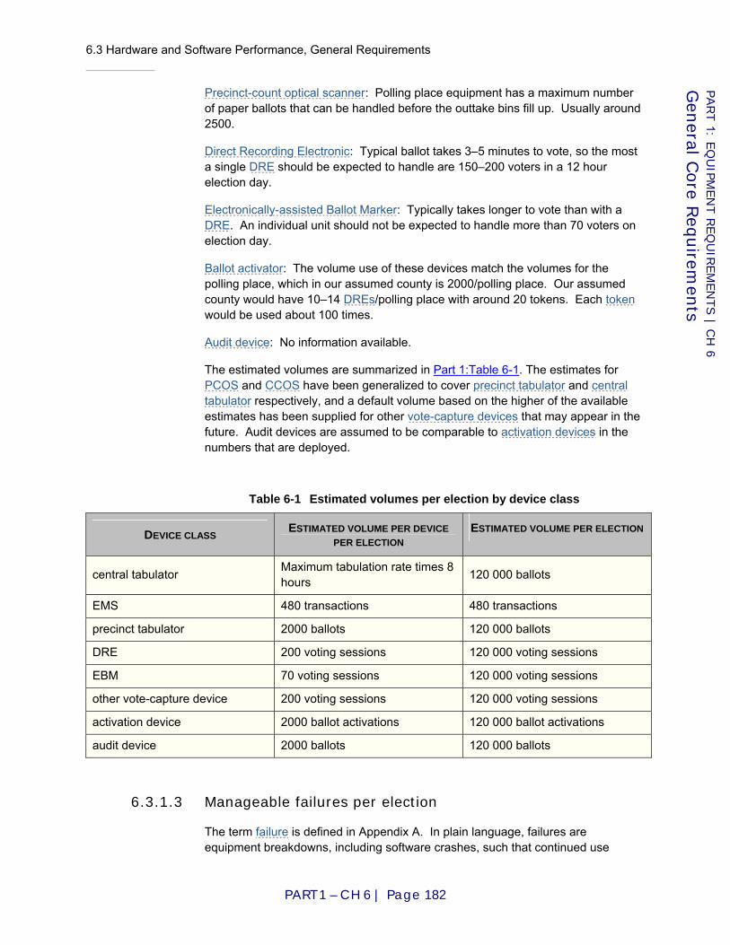
6.3 Hardware and Software Performance, General Requirements
PART 1 – CH 6 | Page 182
PART 1: E
QU
IPM
EN
T R
EQ
UIR
EM
EN
TS | C
H 6
Gen
eral Core R
equirem
ents
Precinct-count optical scanner: Polling place equipment has a maximum number of paper ballots that can be handled before the outtake bins fill up. Usually around 2500.
Direct Recording Electronic: Typical ballot takes 3–5 minutes to vote, so the most a single DRE should be expected to handle are 150–200 voters in a 12 hour election day.
Electronically-assisted Ballot Marker: Typically takes longer to vote than with a DRE. An individual unit should not be expected to handle more than 70 voters on election day.
Ballot activator: The volume use of these devices match the volumes for the polling place, which in our assumed county is 2000/polling place. Our assumed county would have 10–14 DREs/polling place with around 20 tokens. Each token would be used about 100 times.
Audit device: No information available.
The estimated volumes are summarized in Part 1:Table 6-1. The estimates for PCOS and CCOS have been generalized to cover precinct tabulator and central tabulator respectively, and a default volume based on the higher of the available estimates has been supplied for other vote-capture devices that may appear in the future. Audit devices are assumed to be comparable to activation devices in the numbers that are deployed.
Table 6-1 Estimated volumes per election by device class
DEVICE CLASS ESTIMATED VOLUME PER DEVICE PER ELECTION
ESTIMATED VOLUME PER ELECTION
central tabulator Maximum tabulation rate times 8 hours 120 000 ballots
EMS 480 transactions 480 transactions
precinct tabulator 2000 ballots 120 000 ballots
DRE 200 voting sessions 120 000 voting sessions
EBM 70 voting sessions 120 000 voting sessions
other vote-capture device 200 voting sessions 120 000 voting sessions
activation device 2000 ballot activations 120 000 ballot activations
audit device 2000 ballots 120 000 ballots
6.3.1.3 Manageable failures per election
The term failure is defined in Appendix A. In plain language, failures are equipment breakdowns, including software crashes, such that continued use
6.3 Hardware and Software Performance, General Requirements
PART 1 – CH 6 | Page 183
PART 1: E
QU
IPM
EN
T R
EQ
UIR
EM
EN
TS | C
H 6
Gen
eral Core R
equirem
ents
without service or replacement is worrisome to impossible. Normal, routine occurrences like running out of paper are not considered failures. Misfeeds of ballots into optical scanners are handled by a separate benchmark (Requirement Part 1:6.3.3-A), so these are not included as failures for the general reliability benchmark.
The following estimates express what failures would be manageable for a mid-sized county in a high-turnout election. Medium-sized counties send out troubleshooters to polling places to replace or resolve problems with machines.
Any failure that results in all CVRs pertaining to a given ballot becoming unusable or that makes it impossible to determine whether or not a ballot was cast is called disenfranchisement. It is unacceptable for even one ballot to become unrecoverable or to end up in an unknown state. For example, an optical scanner that shreds a paper ballot, rendering it unreadable by human or machine, is assessed a disenfranchisement type failure; so is a DRE that is observed to "freeze," providing no evidence one way or the other whether the ballot was cast, when the voter attempts to cast the ballot.
Central-count optical scanner: No more than one machine breakdown per jurisdiction requiring repairs done by the manufacturer or highly trained personnel. Medium sized jurisdictions plan on having one backup machine for each election.
Election Management System: This is a critical system that must perform in an extremely time sensitive environment for a mid-sized county over a 3 to 4 hour period election night. Any failure during the test that requires the manufacturer or highly trained personnel to recover should disqualify the system. Otherwise, as long as the manufacturer's documentation provides usable procedures for recovering from the failures and methods to verify results and recover any potentially missing election results, 1 failure is assessed for each 10 minutes of downtime (minimum 1 – no fractional failures are assessed). A total of 3 or more such failures disqualifies the system.
Precinct-count optical scanner: A failure in this class of machine has a negligible impact on the ability of voters to vote in the polling place. No more than 1 of the machines in an election experience serious failures that would require the manufacturer or highly trained personnel to repair (e.g., will not boot). No more than 5 % of the machines in the election experience failures that require the attention of a troubleshooter/poll worker (e.g., memory card failure).
Direct Recording Electronic and Electronically-assisted Ballot Marker: No more than 1 % of the machines in an election experience failures that would require the manufacturer or highly trained personnel to repair (e.g., won't boot) and no more than 3 % of the machines in an election experience failures that require the attention of a troubleshooter (e.g., printer jams, recalibration, etc.).
Ballot activator: The media/token should not fail more than 3 % of the time (the county will provide the polling place with more tokens than necessary). No more than 1 of the devices should fail (the device will be replaced by the county troubleshooter).
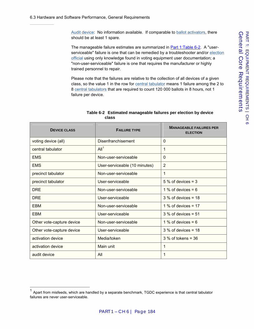
6.3 Hardware and Software Performance, General Requirements
PART 1 – CH 6 | Page 184
PART 1: E
QU
IPM
EN
T R
EQ
UIR
EM
EN
TS | C
H 6
Gen
eral Core R
equirem
ents
Audit device: No information available. If comparable to ballot activators, there should be at least 1 spare.
The manageable failure estimates are summarized in Part 1:Table 6-2. A "user-serviceable" failure is one that can be remedied by a troubleshooter and/or election official using only knowledge found in voting equipment user documentation; a "non-user-serviceable" failure is one that requires the manufacturer or highly trained personnel to repair.
Please note that the failures are relative to the collection of all devices of a given class, so the value 1 in the row for central tabulator means 1 failure among the 2 to 8 central tabulators that are required to count 120 000 ballots in 8 hours, not 1 failure per device.
Table 6-2 Estimated manageable failures per election by device class
DEVICE CLASS FAILURE TYPE MANAGEABLE FAILURES PER ELECTION
voting device (all) Disenfranchisement 0
central tabulator All1 1
EMS Non-user-serviceable 0
EMS User-serviceable (10 minutes) 2
precinct tabulator Non-user-serviceable 1
precinct tabulator User-serviceable 5 % of devices = 3
DRE Non-user-serviceable 1 % of devices = 6
DRE User-serviceable 3 % of devices = 18
EBM Non-user-serviceable 1 % of devices = 17
EBM User-serviceable 3 % of devices = 51
Other vote-capture device Non-user-serviceable 1 % of devices = 6
Other vote-capture device User-serviceable 3 % of devices = 18
activation device Media/token 3 % of tokens = 36
activation device Main unit 1
audit device All 1
1 Apart from misfeeds, which are handled by a separate benchmark, TGDC experience is that central tabulator failures are never user-serviceable.
6.3 Hardware and Software Performance, General Requirements
PART 1 – CH 6 | Page 185
PART 1: E
QU
IPM
EN
T R
EQ
UIR
EM
EN
TS | C
H 6
Gen
eral Core R
equirem
ents
6.3.1.4 Derivation of benchmarks
We focus on one class of device and one type of failure at a time, and we assume that each failure is followed by repair or replacement of the affected device. This means that we consider two failures of the same device to be equivalent to one failure each of two different devices of the same class. The sense of "X % of the machines fail" is thus approximated by a simple failure count, which is X/100 times the number of devices. This then must be related to the total volume processed by the entire group of devices over the course of an election in order to determine the number of failures that would be manageable in an election of that size.
To reduce the likelihood of an unmanageable situation to an acceptably low level, a benchmark is needed such that the probability of occurrence of an unmanageable number of failures for the total volume estimated is "acceptably low." That "acceptably low level" is here defined to be a probability of no more than 1 %, except in the case of disenfranchisement, where the only acceptable probability is 0.
Under the simplifying assumption that failures occur randomly and in a Poisson distribution, the probability of observing n or less failures for volume v and failure rate r is the value of the Poisson cumulative distribution function,
Consequently, given ve (the estimated total volume) and ne (the maximum manageable number of failures for volume ve), the desired benchmark rate rb is found by solving P(ne,rbve)=0.99 for rb. This sets the benchmark rate such that there remains a 1 % risk that a greater number of failures would occur with marginally conforming devices during an election in which they collectively process volume ve. In the case of disenfranchisement, that risk is unacceptable; hence the benchmark is simply set to zero.
6.3.1.5 Requirements
6.3.1-A Failure rate benchmark
All devices SHALL achieve failure rates not exceeding those indicated in Part 1:Table 6-3.
Applies to: Voting device
Test Reference: Part 3:5.3.2 “Critical values”
Source: Revised from [VSS2002] I.3.4.3 / [VVSG2005] I.4.3.3
Table 6-3 Failure rate benchmarks
( ) ( )∑=
−
=n
x
xrv
xrvervnP
0 !,
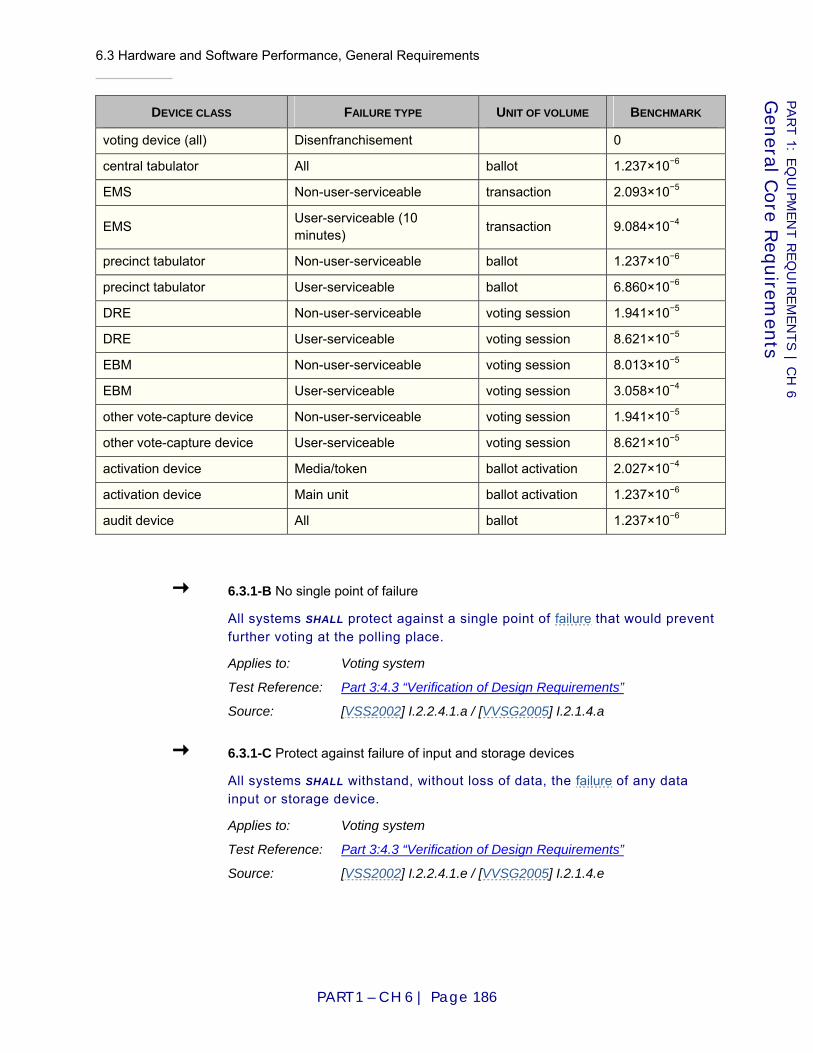
6.3 Hardware and Software Performance, General Requirements
PART 1 – CH 6 | Page 186
PART 1: E
QU
IPM
EN
T R
EQ
UIR
EM
EN
TS | C
H 6
Gen
eral Core R
equirem
ents
DEVICE CLASS FAILURE TYPE UNIT OF VOLUME BENCHMARK
voting device (all) Disenfranchisement 0
central tabulator All ballot 1.237×10⁻⁶
EMS Non-user-serviceable transaction 2.093×10⁻⁵
EMS User-serviceable (10 minutes) transaction 9.084×10⁻⁴
precinct tabulator Non-user-serviceable ballot 1.237×10⁻⁶
precinct tabulator User-serviceable ballot 6.860×10⁻⁶
DRE Non-user-serviceable voting session 1.941×10⁻⁵
DRE User-serviceable voting session 8.621×10⁻⁵
EBM Non-user-serviceable voting session 8.013×10⁻⁵
EBM User-serviceable voting session 3.058×10⁻⁴
other vote-capture device Non-user-serviceable voting session 1.941×10⁻⁵
other vote-capture device User-serviceable voting session 8.621×10⁻⁵
activation device Media/token ballot activation 2.027×10⁻⁴
activation device Main unit ballot activation 1.237×10⁻⁶
audit device All ballot 1.237×10⁻⁶
6.3.1-B No single point of failure
All systems SHALL protect against a single point of failure that would prevent further voting at the polling place.
Applies to: Voting system
Test Reference: Part 3:4.3 “Verification of Design Requirements”
Source: [VSS2002] I.2.2.4.1.a / [VVSG2005] I.2.1.4.a
6.3.1-C Protect against failure of input and storage devices
All systems SHALL withstand, without loss of data, the failure of any data input or storage device.
Applies to: Voting system
Test Reference: Part 3:4.3 “Verification of Design Requirements”
Source: [VSS2002] I.2.2.4.1.e / [VVSG2005] I.2.1.4.e
6.3 Hardware and Software Performance, General Requirements
PART 1 – CH 6 | Page 187
PART 1: E
QU
IPM
EN
T R
EQ
UIR
EM
EN
TS | C
H 6
Gen
eral Core R
equirem
ents
6.3.2 Accuracy/error rate
Since accuracy is measured at the system level, it is not necessary to define different benchmarks for different classes of devices.
6.3.2-A Satisfy integrity constraints
All systems SHALL satisfy the constraints in Part 1:8.3 “Logic Model (normative)”.
Applies to: Voting system
Test Reference: Part 3:4.6 “Logic Verification”
Source: Formalization of general requirements
6.3.2-B End-to-End accuracy benchmark
All systems SHALL achieve a report total error rate of no more than 8×10⁻⁶ (1 / 125 000).
Applies to: Voting system
Test Reference: Part 3:5.3.4 “Accuracy”
D I S C U S S I O N
For the definition of report total error rate, see Requirement Part 3:5.3.4-B.
This benchmark is derived from the "maximum acceptable error rate" used as the lower test benchmark in [VVSG2005]. That benchmark was defined as a ballot position error rate of 2×10⁻⁶ (1 / 500 000).
Given that there is no "typical" ratio of votes to ballot positions with such diversity among the many jurisdictions, it is nevertheless necessary to base the benchmark on some rough estimates in order that it may be in the correct order of magnitude, albeit not optimal for every case. The rough estimates are as follows. In a presidential election, there will be approximately 20 contests with a vote for 1 on each ballot with an average of 4 candidates, including the write-in position, per contest. (Some states will have fewer contests and some more. A few contests, like President, would have 8–13 candidates; most have 3 candidates including the write-in, and a few have 2 candidates.) The estimated ratio of votes to ballot positions is thus ¼.
For paper-based tabulators, this general requirement is elaborated in Part 1:7.7.5 “Accuracy”.
Source: Generalized and clarified from [VSS2002] I.3.2.1 / [VVSG2005] I.4.1.1
Other accuracy-related requirements include Requirement Part 1:6.4.1.7-D, Requirement Part 1:7.1-E, Requirement Part 1:7.1-F, Requirement Part 1:7.5.4-A, and Requirement Part 1:7.8.3.1-B.

6.3 Hardware and Software Performance, General Requirements
PART 1 – CH 6 | Page 188
PART 1: E
QU
IPM
EN
T R
EQ
UIR
EM
EN
TS | C
H 6
Gen
eral Core R
equirem
ents
6.3.3 Misfeed rate
6.3.3-A Misfeed rate benchmark
The misfeed rate SHALL NOT exceed 0.002 (1 / 500).
Applies to: Paper-based device ⋀ Tabulator, EBM
Test Reference: Part 3:5.3.5 “Misfeed rate”
D I S C U S S I O N
Multiple feeds, misfeeds (jams), and rejections of ballots that meet all manufacturer specifications are all treated collectively as "misfeeds" for benchmarking purposes; i.e., only a single count is maintained.
Source: Merge of [VSS2002] I.3.2.5.1.4.b and I.3.2.5.2.c, reset benchmark
6.3.4 Electromagnetic Compatibility (EMC) immunity
The International Electrotechnical Commission (IEC) Technical Committee 77 on Electromagnetic Compatibility has defined [ISO95a] the concept of “ports” as the interface of an electronic device (“apparatus”) with its electrical and electromagnetic environment, as illustrated in Part 1:Figure 6-1. In the sketch, the arrows point toward the apparatus, but in a complete assessment of the compatibility, one should also consider the other direction – that is, what disturbances (“emissions”) can the apparatus inject into its environment.
Figure 6-1 Electrical and electromagnetic environment
Five of these ports involve conducted disturbances carried by metallic conductors, and the sixth, the “enclosure,” allows radiated disturbances to impinge on the apparatus. In this context, the term “enclosure” should not be understood as limited to a physical entity (metallic, non metallic, totally enclosed or with openings) but rather be understood as simply the route whereby electromagnetic radiations couple with the circuitry and components of the apparatus.
In previous voting systems guidelines, possible interactions and immunity concerns have been described but perhaps not in explicit terms relating them to the concept of ports. In this updated version of the VVSG, the recitation of compatibility requirements is structured by considering the ports one at a time, plus some consideration of a possible interaction between ports:
6.3 Hardware and Software Performance, General Requirements
PART 1 – CH 6 | Page 189
PART 1: E
QU
IPM
EN
T R
EQ
UIR
EM
EN
TS | C
H 6
Gen
eral Core R
equirem
ents
1. Power port – also described as “power supply” – via ordinary receptacles of the polling place
2. Earth port – implied in the National Electric Code [NFPA05] stipulations for dealing with the power supply of the polling place
3. Signal port – connection to the landline telephone of the polling place to the central tabulator
4. Control port – inter-system connections such as voting station to precinct tabulator
5. Enclosure port – considerations on immunity to radiated disturbances and electrostatic discharge
6. Interaction between signal port and power port during surge events
Note: In this EMC section, the specified voltage and current levels are expressed in root mean square (rms) for power-frequency parameters and in peak value for surges and impulses.
6.3.4.2 Steady-state conditions
Adequate operation of an eventual surge-protective device and, more important, safety considerations demand that the power supply receptacles be of the three-prong type (Line, Neutral, and Equipment Grounding Conductor). The use of a “cheater” adapter for older type receptacles with only two-blade capacity and no dependable grounding conductor should be prohibited. Details on the safety considerations are addressed in Part 1:3.2.8.2 “Safety”.
The requirement of using a dedicated landline telephone service should also be satisfied for polling places.
Steady state conditions of a polling place are generally out of the control of the local jurisdiction.
However, for a polling place to ensure reliable voting, the power supply and telephone service need to be suitable for the purpose. Compliance with the National Electrical Code [NFPA05] is assumed to be required.
6.3.4.2-A Power supply – energy service provider
To obtain maximum flexibility of application, the voting system SHALL be powered by a 120 V, single phase power supply, as available in polling places, derived from typical energy service providers.
Applies to: Electronic device
Test Reference: Part 3:3.1 “Inspection”
D I S C U S S I O N
It is assumed that the AC power necessary to operate the voting system will be derived from the existing power distribution system of the facility housing the polling place. This single-phase power may be a leg of a 120/240 V single phase system, or a leg of a 120/208 V three-phase system, at a frequency of 60 Hz,

6.3 Hardware and Software Performance, General Requirements
PART 1 – CH 6 | Page 190
PART 1: E
QU
IPM
EN
T R
EQ
UIR
EM
EN
TS | C
H 6
Gen
eral Core R
equirem
ents
according to the limits defined in [ANSI06], and premises wiring compliant with the [NFPA05], in particular its grounding requirements.
Source: [NFPA05]
6.3.4.2-B Telecommunications services provider
To avoid compromising voting integrity (accidentally or intentionally), the telephone connection of a voting system SHALL use a dedicated line (no extensions on the same telephone number) and be compatible with the requirements of the telephone service provider.
Applies to: Electronic device
Test Reference: Part 3:3.1 “Inspection”
D I S C U S S I O N
Communications (upon closing of the poll) between the polling place and the central tabulator is expected to be provided exclusively by the landline network of the telephone service provider connected to the facility housing the polling place. The use of cell phone communications is specifically prohibited.
Source: New requirement
6.3.4.3 Conducted disturbances immunity
As described in the introductory paragraphs of Part 1:6.3.4 “Electromagnetic Compatibility (EMC) immunity”, several ports of the voting system are gateways to possible electromagnetic disturbances, both inbound and outbound. This section dealing with conducted disturbances immunity addresses concerns about the power port and the communications ports (a combination of the in-house communications and communications to remote tabulating facilities).
Limitations of outbound conducted disturbances (“emissions” in EMC language) that might inject objectionable interference into the facility power distribution system or the telephone service connection are addressed in Part 1:6.3.5 “Electromagnetic Compatibility (EMC) emission limits”.
6.3.4.3-A Power port disturbances
All electronic voting systems SHALL withstand conducted electrical disturbances that affect the power ports of the system.
Applies to: Electronic device
Test Reference: Part 3:5.1.1.2-A
D I S C U S S I O N
The power distribution system of the polling place can be expected to be affected by several types of disturbances, ranging from very brief surges (microseconds) to longer durations (milliseconds) and ultimately the possibility of a long-term outage. These are addressed in the following requirements: A.1, A.2, A.3, and A.4.
6.3 Hardware and Software Performance, General Requirements
PART 1 – CH 6 | Page 191
PART 1: E
QU
IPM
EN
T R
EQ
UIR
EM
EN
TS | C
H 6
Gen
eral Core R
equirem
ents
NOTE: There are several scenarios of accidental conditions that can produce voltages far in excess of the deviations implied by [ANSI06] or [ITIC00], such as loss of a neutral conductor, commingling of distribution systems with low-voltage conductors (knocked down poles, falling tree limbs). Such an event will produce in the building massive failures of equipment other than voting systems, and be obvious to the officials conducting the polling. Hardware failure of the voting system can be expected. Fortunately, the occurrence of such events is quite rare, albeit not impossible, so that such a extreme stress should not be included in the EMC requirements nor in the regimen of national certification testing – provided that the failure mode would not result in a safety hazard.
Source: [ANSI06], [IEEE02a], [ITIC00]
6.3.4.3-A.1 Combination Wave
All electronic voting systems SHALL be able to withstand, without disruption of normal operation or loss of data, a “Combination Wave” surge of 6 kV 1.2/50 µs, for high impedance power ports and 3 kA 8/20 µs, for low impedance power ports, between line and neutral terminals.
Applies to: Electronic device
Test Reference: Part 3:5.1.1.2-A.1
D I S C U S S I O N
The so-called “Combination Wave” has been accepted by industry as representative of surges that might occur in low-voltage AC power systems and be imposed on connected loads.
Source: [IEEE02a]
6.3.4.3-A.2 Ring Waves
All electronic voting systems SHALL be able to withstand, without disruption of normal operation or loss of data, a “Ring Wave” surge with a 0.5 µs rise time and a decaying oscillation at 100 kHz with a first peak voltage of 6 kV between the line and neutral terminals, and between the line and equipment grounding conductor terminals, and also 3 kV between the neutral and equipment grounding conductor terminals.
Applies to: Electronic device
Test Reference: Part 3:5.1.1.2-A.2
D I S C U S S I O N
This test waveform, proposed by IEEE since 1980 [IEEE80] as a “Standard Waveform,” and more recently adopted by the IEC [ISO06c] represents common disturbances on AC power lines but it was not included in previous versions of the VVSG. It originates during disturbances of power flow within the building, an occurrence more frequent than lightning surges. It is less likely than the Combination Wave to produce hardware destruction, but high levels still can produce hardware failure.
6.3 Hardware and Software Performance, General Requirements
PART 1 – CH 6 | Page 192
PART 1: E
QU
IPM
EN
T R
EQ
UIR
EM
EN
TS | C
H 6
Gen
eral Core R
equirem
ents
The “Power Quality” literature [Grebe96] and some standards [IEEE91] also cite “Decaying Ring Waves” or “Damped Oscillatory Waves” with lower frequencies but lesser amplitudes typically associated with the switching of power-factor correction capacitors. These can be significant for surge-protective device survival and possibly disruption of the operation of switched-mode power supplies. However, inclusion of the Combination Wave, the Ring Wave, and the Swells in these immunity criteria should be sufficient to ensure immunity against these lower frequency and lower amplitude decaying ring waves.
Source: [IEEE02a]
6.3.4.3-A.3 Electrical Fast Transient Burst
All electronic voting systems SHALL be able to withstand, without disruption of normal operation or loss of data, a burst of repetitive fast transients with a waveform of 5/50 ns, each burst lasting 15 ms, from a 2 kV source.
Applies to: Electronic device
Test Reference: Part 3:5.1.1.2-A.3
D I S C U S S I O N
While the fast transients involved in this immunity requirement do not propagate very far and are not expected to travel from the energy supply provider, they can be induced within a facility if cable runs are exposed to switching disturbances in other load circuits. Unlike the preceding two disturbances that are deemed to represent possibly destructive surges, the Electrical Fast Transient (EFT) Burst has been developed to demonstrate equipment immunity to these non-destructive but disruptive transients. Their repetitive profile increases the probability that a disruption might occur when the logic circuits go through a transition. It is important to recognize that this test, which does not represent the actual environment, is one of interference immunity, not a test of withstanding energy stress.
Source: [IEEE02a]
6.3.4.3-A.4 Outages, sags and swells
All electronic voting systems SHALL be able to withstand, without disruption of normal operation or loss of data, a complete loss of power lasting two hours and also a temporary overvoltage of up to 120 % of nominal system voltage lasting up to 0.5 second, and a permanent overvoltage of up to 110 % of nominal system voltage.
Applies to: Electronic device
Test Reference: Part 3:5.1.1.2-A.4
D I S C U S S I O N
Because the VVSG stipulates a two-hour back up, generally implemented by a floating battery pack, sag immunity is inherently ensured. However, the floating battery, unless buffered by a switch-mode power supply with inherent cut-off in case of a large swell, might not ensure inherent immunity against swells (short
6.3 Hardware and Software Performance, General Requirements
PART 1 – CH 6 | Page 193
PART 1: E
QU
IPM
EN
T R
EQ
UIR
EM
EN
TS | C
H 6
Gen
eral Core R
equirem
ents
duration system overvoltages). The Information Technology industry has adopted a recommendation that IT equipment should be capable to operate correctly for swells reaching 120 % of the nominal system voltage with duration ranging from 3 ms to 0.5 s and permanent overvoltages up to 110 % of nominal system voltage.
Source: [ITIC00]
6.3.4.3-B Communications (telephone) port disturbances
All electronic voting systems SHALL withstand conducted electrical disturbances that affect the telephone ports of the system.
Applies to: Electronic device
Test Reference: Part 3:5.1.1.2-B
D I S C U S S I O N
Voting equipment, by being connected to the outside service provider via premises wiring, can be exposed to a variety of electromagnetic disturbances. These have been classified as lightning-induced, power-fault induced, power contact, Electrical Fast Transient (EFT), and presence of steady-state induced voltage. Within a complex voting system installed in a polling place, there is also a possibility that the various pieces of equipment can be exposed to emissions from other piece of connected equipment. In the context of the VVSG compatibility, not only must the voting system equipment be immune to these disturbances, but also the public switched telephone network must be protected against harm originating from customer premises equipment, in this context the voting system equipment. Protection of the network is discussed in the Part 1:6.3.5 “Electromagnetic Compatibility (EMC) emission limits”. Immunity to disturbances impinging on the voting system telephone port is addressed in the following requirements: B.1, B.2, B.3, B.4, B.5, and B.6.
Source: [Telcordia06]
6.3.4.3-B.1 Emissions from other connected equipment
All elements of an electronic voting system SHALL be able to withstand the conducted emissions generated by other elements of the voting system.
Applies to: Electronic device
Test Reference: Part 3:5.1.1.2-B.1
D I S C U S S I O N
This requirement is an issue of inherent compatibility among the diverse elements of a voting system, not compatibility with the polling place environment or subscriber equipment other than those making up the voting system. It is understood and implemented that security requirements dictate that the voting system outgoing communications be provided by a dedicated landline telephone service excluding other subscriber terminal equipment otherwise used by entities occupying the facility when telephone communication with central tabulators is established.
Source: [Telcordia06], [ANSI02]

6.3 Hardware and Software Performance, General Requirements
PART 1 – CH 6 | Page 194
PART 1: E
QU
IPM
EN
T R
EQ
UIR
EM
EN
TS | C
H 6
Gen
eral Core R
equirem
ents
6.3.4.3-B.2 Lightning-induced disturbances
All electronic voting systems SHALL be able to withstand, without disruption of normal operation or loss of data, the stresses induced into the telephone network by lightning events, which can propagate to the telephone port of the voting system. The necessary immunity level is 1 kV for high-impedance ports and 100 A for low-impedance ports, both with a 10/1000 µs waveshape.
Applies to: Electronic device
Test Reference: Part 3:5.1.1.2-B.2
D I S C U S S I O N
Lightning events (direct flashes to the network or voltages induced in the network by nearby flashes to earth) can be at the origin of voltage surges or current surges impinging upon the interface of the premises wiring with the landline network. The provision of surge protection in the Network Interface Device (primary protection NID) is not universally provided, especially in dense urban locations, therefore the immunity level of the telephone port should be demonstrated as required by the Telcordia Generic Requirements.
Source: [Telcordia06]
6.3.4.3-B.3 Power fault-induced disturbances
All electronic voting systems SHALL be able to withstand, without disruption of normal operation or loss of data, the stresses induced into the network by power faults occurring in adjacent power distribution systems. The necessary immunity level is 600 V at 1 A for a 1 s application.
Applies to: Electronic device
Test Reference: Part 3:5.1.1.2-B.3
D I S C U S S I O N
For overhead telephone landline cables that share the pole with power distribution cables (medium-voltage as well as low-voltage), as well as direct burial of adjacent telephone and power cables, large power system faults can induce significant voltages and the resulting currents in the telephone network.
Source: [Telcordia06]
6.3.4.3-B.4 Power contact disturbances
All electronic voting systems SHALL be able to withstand, without disruption of normal operation or loss of data, the stresses appearing at the telephone port as a result from an accidental contact between the telephone network cables and nearby power distribution cables. The necessary immunity level between ground and the T/R conductors at 60 Hz is 600 V for short durations and 277 V for indefinite durations.
Applies to: Electronic device
6.3 Hardware and Software Performance, General Requirements
PART 1 – CH 6 | Page 195
PART 1: E
QU
IPM
EN
T R
EQ
UIR
EM
EN
TS | C
H 6
Gen
eral Core R
equirem
ents
Test Reference: Part 3:5.1.1.2-B.4
D I S C U S S I O N
Outside of the polling place building, accidental contact between the telephone network cables and power distribution cables (sharing poles for overhead, or sharing trenches for underground) can inject substantial 60 Hz current and voltages into the telephone network. Within the polling place facility, while not at high probability, instances have been noted whereby contractors working in a facility can provoke a similar injection of 60 Hz current or voltage into the premises telephone wiring. The 600 V level cited in the above requirement is associated with an accidental contact with primary power lines, promptly cleared by the power system protection, while the 277 V level is associated with an accidental contact with low-voltage distribution system that might not be cleared by the power system protection.
Source: [Telcordia06]
6.3.4.3-B.5 Electrical Fast Transient (EFT)
All electronic voting systems SHALL be able to withstand, without disruption of normal operation or loss of data, the disturbances associated with an EFT burst of 5/50 ns pulses, each burst lasting 15 ms, from a 0.25 kV source.
Applies to: Electronic device
Test Reference: Part 3:5.1.1.2-B.5
D I S C U S S I O N
Electrical Fast Transient bursts emulate the interference associated with electromagnetic coupling between the premises wiring of the telephone service and the premises wiring of the power distribution system in which switching surges can occur. Because these switching surges are random events, the occurrence of interference varies with the timing of their occurrence with respect to the transitions of the circuits. It is important to recognize that this requirement deals with interference immunity, not with withstanding energy stress. Immunity against such high-frequency coupling has been added to the requirements listed by [Telcordia06], effective January 1, 2008.
Source: [Telcordia06], [ISO04b]
6.3.4.3-B.6 Steady-state induced voltage
All electronic voting systems SHALL be able to withstand, without disruption of normal operation or loss of data, the disturbances associated with steady-state induced voltages and currents. The necessary immunity level is ≥126 dBrn (50 V).
Applies to: Electronic device
Test Reference: Part 3:5.1.1.2-B.6

6.3 Hardware and Software Performance, General Requirements
PART 1 – CH 6 | Page 196
PART 1: E
QU
IPM
EN
T R
EQ
UIR
EM
EN
TS | C
H 6
Gen
eral Core R
equirem
ents
D I S C U S S I O N
Voting systems interfacing with the telephone service provider plant can be subject to the interfering effects of steady-state voltages induced from nearby power lines. Through electromagnetic coupling, normal operating currents on these power lines can induce common-mode (longitudinal) voltages and currents in the outside cable plant. The 60 Hz and 180 Hz components of the induced voltage spectrum can interfere with signaling and supervisory functions for data transmission from a polling place toward a central tabulator. Higher frequencies can produce audible noise in voice-band transmission.
Source: [Telcordia06]
6.3.4.3-C Interaction between power port and telephone port
All electronic voting systems connected to both a power supply and a landline telephone system SHALL withstand the potential difference caused by the flow of surge current in the facility grounding network.
Applies to: Electronic device
Test Reference: Part 3:5.1.1.2-C
D I S C U S S I O N
A voting system that is powered via its power port to the power distribution system of the facility and to the telephone service provider via its telephone port can experience a potentially damaging stress between the two ports during the expected operation of the telephone network interface device in the event of a surge occurring in the telephone system. Because the level of potential differences during a surge event is principally the result of the local configuration of the premises wiring and grounding systems, and thus beyond the control of the local polling entity, inherent immunity of the voting system can be achieved by incorporating a surge reference equalizer that provides the necessary bonding between the input power port and telephone port during a surge event.
Source: [IEEE02], [IEEE05]
6.3.4.4 Radiated disturbances immunity
This section discusses radiated disturbances impacting the enclosure port of the voting system, including electromagnetic fields originating from adjacent or distant sources, as well as a particular radiation associated with electrostatic discharge.
Emissions limits requirements of radiated (and conducted) disturbances are addressed in Part 1:6.3.5.2 ‘Radiated emissions”.
6.3.4.4-A Electromagnetic field immunity (80 MHz to 6.0 GHz)
All electronic voting systems SHALL withstand, without disruption of normal operation or loss of data, exposure to radiated electromagnetic fields of ≥10 V/m over the entire frequency range of 80 MHz to 6.0 GHz, and ≥30 V/m within frequency bands commonly used by portable transmitters.
Applies to: Electronic device
6.3 Hardware and Software Performance, General Requirements
PART 1 – CH 6 | Page 197
PART 1: E
QU
IPM
EN
T R
EQ
UIR
EM
EN
TS | C
H 6
Gen
eral Core R
equirem
ents
Test Reference: Part 3:5.1.1.3-A
D I S C U S S I O N
The proliferation of portable transmitters (cellular telephones and personal communications systems) used by the general population and the common communications transmitters used by security, public safety, amateur radio, and other services increases the likelihood that the voting equipment covered in the VVSG will be exposed to the radiated electromagnetic fields from these devices. Also, other wireless devices (wireless local area networks, etc.), communications and broadcast transmitters may be operating in the vicinity and need to be considered. Since it may be impractical to eliminate nearby radio-frequency sources, voting systems must demonstrate immunity to these signals in order to operate to a high standard of reliability. This requirement is intended to ensure intrinsic immunity to the electromagnetic environment.
Source: [ANSI97], [ISO06a], [ISO06d]
6.3.4.4-B Electromagnetic field immunity (150 kHz to 80 MHz)
All electronic voting systems SHALL withstand, without disruption of normal operation or loss of data, exposure to radio-frequency energy induced on cables in the frequency range of 150 kHz to 80 MHz at a 10 V level.
Applies to: Electronic device
Test Reference: Part 3:5.1.1.3-B
D I S C U S S I O N
The dominant coupling mechanism of radiated electromagnetic fields to equipment electronics at frequencies below 80 MHz is considered to be through currents induced on interconnecting cables. At these frequencies, the wavelengths are such that typical circuit components are electrically very small and thus inefficient in coupling energy directly from the radiated electromagnetic fields. The interconnecting cables, on the other hand, tend to be on the order of the signal wavelengths and may act as efficient and possibly resonant antennas. Thus, the radiated electromagnetic fields will efficiently induce currents on these cables that are connected directly to the equipment electronics.
Source: [ANSI97], [ISO06b]
6.3.4.4-C Electrostatic discharge immunity
All electronic voting systems SHALL withstand, without disruption of normal operation or loss of data, electrostatic discharges associated with human contact and contact with mobile equipment (service carts, wheelchairs, etc.).
Applies to: Electronic device
Test Reference: Part 3:5.1.1.3-C
D I S C U S S I O N
Electrostatic discharge events can originate from direct contact between an “intruder” (person or object) charged at a potential different from that of the units of
6.3 Hardware and Software Performance, General Requirements
PART 1 – CH 6 | Page 198
PART 1: E
QU
IPM
EN
T R
EQ
UIR
EM
EN
TS | C
H 6
Gen
eral Core R
equirem
ents
the voting system, or from an approaching person about to touch the equipment – an “air discharge.” The resulting discharge current can induce disturbances in the circuits of the equipment.
Note: The immunity addressed in this section is concerned with normal operations and procedures at the polling place. It does not include immunity to electrostatic discharges that might occur when service personnel open the enclosure and handle internal components.
Source: [ANSI93], [ISO01]
6.3.5 Electromagnetic Compatibility (EMC) emission limits
“Emission limits” are the companion of “Immunity Requirements” – both are necessary to achieve electromagnetic compatibility. In contrast with immunity requirements that are expressed as withstand levels for the equipment, emission limits requirements are expressed as compliance with consensus-derived limits on the parameters of the disturbances injected in the electromagnetic environment by the operation of the voting system.
6.3.5.1 Conducted emissions
Electronic voting systems, by their nature, can generate currents or voltages that will exit via their connecting cables to the power supply or to the telephone service provider of the voting facility. To ensure compatibility, industry standards or mandatory regulations have been developed to define maximum levels of such emissions.
6.3.5.1-A Power port connection to the facility power supply
All electronic voting systems installed in a polling place SHALL comply with emission limits affecting the power supply connection to the energy service provider according to Federal Regulations [FCC07].
Applies to: Electronic device
Test Reference: Part 3:5.1.2.1 “Conducted emissions limits”
D I S C U S S I O N
The normal operation of an electronic system can produce disturbances that will travel upstream an affect the power supply system of the polling place, creating a potential deviation from the expected electromagnetic compatibility of the system. The issue is whether these actual disturbances (after possible mitigation means incorporated in the equipment) reach a significant level to exceed stipulated limits, which include the following categories:
1. Harmonic emissions associated with the load current drawn by the voting system. However, given the low values of the current drawn by the voting system, these emissions do not represent a significant issue, as explained in [IEEE92]. They are only mentioned here for the sake of completeness in reciting the range of disturbances and therefore do not require testing.

6.3 Hardware and Software Performance, General Requirements
PART 1 – CH 6 | Page 199
PART 1: E
QU
IPM
EN
T R
EQ
UIR
EM
EN
TS | C
H 6
Gen
eral Core R
equirem
ents
2. High-frequency conducted emissions (distinct from the harmonic spectrum) into the power cord by coupling from high-frequency switching or data transmission inherent to the system operation. These are addressed in the mandatory certification requirements of [FCC07], Class B.
Source: [IEEE92], [FCC07]
6.3.5.1-B Telephone port connection to the public network
All electronic voting systems installed in a polling place SHALL comply with emission limits stipulated by the industry-recognized organizations of telephone service providers Telcordia [Telcordia06] and TIA [ANSI02].
Applies to: Electronic device
Test Reference: Part 3:5.1.2.1-A
D I S C U S S I O N
Regulatory emission limits requirements for protecting the network (public switched telephone network) from harm via customer premises equipment are contained in the source documents [Telcordia06], [ANSI02], [FCC07a] and compliance to these documents is considered mandatory for offering the equipment on the market.
Source: [Telcordia06], [ANSI02], [FCC07a]
6.3.5.1-C Leakage via grounding port
All electronic voting systems installed in a polling place SHALL comply with limits of leakage currents effectively established by the trip threshold of all listed Ground Fault Current Interrupters (GFCI), if any, installed in the branch circuit supplying the voting system.
Applies to: Electronic device
Test Reference: Part 3:5.1.3.2-A
D I S C U S S I O N
Excessive leakage current is objectionable for two reasons:
1. For a branch circuit or wall receptacle that could be provided with a GFCI (depending upon the wiring practice applied at the particular polling place), leakage current above the GFCI built-in trip point would cause the GFCI to trip and therefore disable the operation of the system.
2. Should the power cord lose the connection to the equipment grounding conductor of the receptacle, a personnel hazard would occur. (Note the prohibition of “cheater” adapters in the discussion of general requirements for the polling place.)
This requirement is related to safety considerations as discussed in Part 1:3.2.8.2 “Safety” – in particular the requirement to have the voting system comply with [UL05].
Note: According to [NFPA05], a bond between the equipment grounding conductor and the neutral conductor is prohibited downstream from the entrance service
6.3 Hardware and Software Performance, General Requirements
PART 1 – CH 6 | Page 200
PART 1: E
QU
IPM
EN
T R
EQ
UIR
EM
EN
TS | C
H 6
Gen
eral Core R
equirem
ents
panel. GFCIs are designed to trip if such a prohibited bond is detected by the GFCI.
Source: [UL06], [NFPA05]
6.3.5.2 Radiated emissions
6.3.5.2-A Radiated radio frequency emissions
All electronic voting systems installed in a polling place SHALL comply with emission limits according to the Rules and Regulations of the Federal Communications Commission, Part 15, Class B [FCC07] for radiated radio-frequency emissions.
Applies to: Electronic device
Test Reference: Part 3:5.1.2.2-A
D I S C U S S I O N
Electronic equipment in general and modern high-speed digital electronic circuits in particular have the potential to produce unintentional radiated and conducted radio-frequency emissions over wide frequency ranges. These unintentional signals can interfere with the normal operation of other equipment, especially radio receivers, in close proximity. The requirements of [FCC07] and [ANSI06a] are intended to minimize this possible interference and control the level of unwanted radio-frequency signals in the environment.
Source: [FCC07]
6.3.6 Other requirements
In addition to the requirements associated with EMC discussed in the preceding sections, there are other requirements, including dielectric withstand, personnel safety considerations (addressed in Part 1:3.2.8.2 “Safety”) and hardware failure modes (which can also be a safety issue) [UL05].
6.3.6.1 Dielectric withstand
6.3.6.1-A Dielectric stresses
All electronic voting systems SHALL be able to withstand the dielectric test stresses associated with connection to the network, characterized by limits of the admissible leakage current.
Applies to: Electronic device
Test Reference: Part 3:5.1.3.1-A
D I S C U S S I O N
Dielectric withstand requirements stipulated by industry-consensus telephone requirements as a condition for connecting equipment to their network involve the

6.4 Workmanship
PART 1 – CH 6 | Page 201
PART 1: E
QU
IPM
EN
T R
EQ
UIR
EM
EN
TS | C
H 6
Gen
eral Core R
equirem
ents
insulation and leakage current limits between elements of the voting system hardware, including the following:
1. Network and device or accessible circuitry which might in turn connect to the user;
2. Network and hazardous power system; and
3. Power equipment. Source: [Telcordia06]
6.4 Workmanship
This section contains requirements for voting system materials, and for good design and construction workmanship for software and hardware:
♦ Software engineering practices;
♦ Quality assurance and configuration management;
♦ General build quality;
♦ Durability;
♦ Security and audit architectural requirements;
♦ Maintainability;
♦ Temperature and humidity; and
♦ Equipment transportation and storage.
6.4.1 Software engineering practices
This section describes essential design and performance characteristics of the logic used in voting systems. The requirements of this section are intended to ensure that voting system logic is reliable, robust, testable, and maintainable.
The general requirements of this section apply to logic used to support the entire range of voting system activities. Although this section emphasizes software, the standards described also influence hardware design considerations.
While there is no best way to design logic, the use of outdated and ad hoc practices is a risk factor for unreliability, unmaintainability, etc. Consequently, these VVSG require the use of modern programming practices. The use of widely recognized and proven logic design methods will facilitate the analysis and testing of voting system logic.
6.4.1.1 Scope
The design requirements of this section apply to all application logic, regardless of the ownership of the logic or the ownership and location of the hardware on which the logic is installed or operates. Although it would be desirable for COTS software to conform to the design requirements on workmanship, its conformity to those requirements could not be assessed without access to the source code; hence, the

6.4 Workmanship
PART 1 – CH 6 | Page 202
PART 1: E
QU
IPM
EN
T R
EQ
UIR
EM
EN
TS | C
H 6
Gen
eral Core R
equirem
ents
design requirements are scoped to exclude COTS software. However, where there are functional requirements, the behaviors of COTS software and hardware are constrained. (N.B., the definition of COTS precludes any application logic from receiving a COTS designation.)
Third-party logic, border logic, and configuration data are not required to conform to the design requirements on workmanship, but manufacturers are required to supply that source code and data to the test lab to enable a complete review of the application logic (Requirement Part 2:3.4.7.2-E, Requirement Part 2:3.8-D).
6.4.1.2 Selection of programming languages
6.4.1.2-A Acceptable programming languages
Application logic SHALL be produced in a high-level programming language that has all of the following control constructs:
a. Sequence; b. Loop with exit condition (e.g., for, while, and/or do-loops); c. If/Then/Else conditional; d. Case conditional; and e. Block-structured exception handling (e.g., try/throw/catch).
Applies to: Programmed device
Test Reference: Part 3:4.5.1 “Workmanship”
D I S C U S S I O N
The intent of this requirement is clarified in Part 1:6.4.1.5 “Structured programming” with discussion and examples of specific programming languages.
By excluding border logic, this requirement allows the use of assembly language for hardware-related segments, such as device controllers and handler programs. It also allows the use of an externally-imposed language for interacting with an Application Program Interface (API) or database query engine. However, the special code should be insulated from the bulk of the code, e.g. by wrapping it in callable units expressed in the prevailing language, to minimize the number of places that special code appears. C.f. [MIRA04] Rule 2.1: "Assembly language shall be encapsulated and isolated."
Acceptable programming languages are also constrained by Requirement Part 1:6.4.1.7-A.3 and Requirement Part 1:6.4.1.7-A.4, which effectively prohibit the invention of new languages.
Source: [VVSG2005] I.5.2.1, I.5.2.4 and II.5.4.1
6.4.1.2-A.1 COTS language extensions are acceptable
Requirement Part 1:6.4.1.2-A may be satisfied by using COTS extension packages to add missing control constructs to languages that could not otherwise conform. Test Reference: Part 3:4.5.1 “Workmanship”

6.4 Workmanship
PART 1 – CH 6 | Page 203
PART 1: E
QU
IPM
EN
T R
EQ
UIR
EM
EN
TS | C
H 6
Gen
eral Core R
equirem
ents
D I S C U S S I O N
For example, C99 [ISO99] does not support block-structured exception handling, but the construct can be retrofitted using (e.g.) [Sourceforge00] or another COTS package.
The use of non-COTS extension packages or manufacturer-specific code for this purpose is not acceptable, as it would place an unreasonable burden on the test lab to verify the soundness of an unproven extension (effectively a new programming language). The package must have a proven track record of performance supporting the assertion that it would be stable and suitable for use in voting systems, just as the compiler or interpreter for the base programming language must.
Source: Tightening of [VVSG2005] I.5.2.4 and II.5.4.1
6.4.1.3 Selection of general coding conventions
6.4.1.3-A Acceptable coding conventions
Application logic SHALL adhere to a published, credible set of coding rules, conventions or standards (herein simply called "coding conventions") that enhance the workmanship, security, integrity, testability, and maintainability of applications.
Applies to: Programmed device
Test Reference: Part 3:4.5.1 “Workmanship”
D I S C U S S I O N
Coding conventions that are excessively specialized or simply inadequate may be rejected on the grounds that they do not enhance one or more of workmanship, security, integrity, testability, and maintainability.
See the discussion for Requirement Part 1:6.4.1.2-A regarding border logic.
Source: Rewrite of [VSS2002] I.4.2.6
6.4.1.3-A.1 Published
Coding conventions SHALL be considered published if and only if they appear in a publicly available book, magazine, journal, or new media with analogous circulation and availability, or if they are publicly available on the Internet. Test Reference: Part 3:4.5.1 “Workmanship”
D I S C U S S I O N
This requirement attempts to clarify the "published, reviewed, and industry-accepted" language appearing in previous iterations of the VVSG, but the intent of the requirement is unchanged.
Following are examples of published coding conventions (links valid as of 2007-02). These are only examples and are not necessarily the best available for the purpose.
6.4 Workmanship
PART 1 – CH 6 | Page 204
PART 1: E
QU
IPM
EN
T R
EQ
UIR
EM
EN
TS | C
H 6
Gen
eral Core R
equirem
ents
1. Ada: Christine Ausnit-Hood, Kent A. Johnson, Robert G. Pettit, IV, and Steven B. Opdahl, Eds., Ada 95 Quality and Style, Lecture Notes in Computer Science #1344, Springer-Verlag, 1995-06. Content available at http://www.iste.uni-stuttgart.de/ps/ada-doc/style_guide/cover.html and elsewhere.
2. C++: Mats Henricson and Erik Nyquist, Industrial Strength C++, Prentice-Hall, 1997. Content available at http://hem.passagen.se/erinyq/industrial/.
3. C#: "Design Guidelines for Class Library Developers," Microsoft. http://www.msdn.microsoft.com/library/default.asp?url=/library/en-us/cpgenref/html/cpconnetframeworkdesignguidelines.asp.
4. Java: "Code Conventions for the Java™ Programming Language," Sun Microsystems. http://java.sun.com/docs/codeconv/.
Source: Clarification of [VSS2002] I.4.2.6
6.4.1.3-A.2 Credible
Coding conventions SHALL be considered credible if and only if at least two different organizations with no ties to the creator of the rules or to the manufacturer seeking conformity assessment, and which are not themselves voting equipment manufacturers, independently decided to adopt them and made active use of them at some time within the three years before conformity assessment was first sought. Test Reference: Part 3:4.5.1 “Workmanship”
D I S C U S S I O N
This requirement attempts to clarify the "published, reviewed, and industry-accepted" language appearing in previous iterations of the VVSG, but the intent of the requirement is unchanged.
Coding conventions evolve, and it is desirable for voting systems to be aligned with modern practices. If the "three year rule" was satisfied at the time that a system was first submitted for testing, it is considered satisfied for the purpose of subsequent reassessments of that system. However, new systems must meet the three year rule as of the time that they are first submitted for testing, even if they reuse parts of older systems.
Source: Clarification of [VSS2002] I.4.2.6
6.4.1.4 Software modularity and programming
6.4.1.4-A Modularity
Application logic SHALL be designed in a modular fashion.
Applies to: Programmed device
Test Reference: Part 3:4.5.1 “Workmanship”
6.4 Workmanship
PART 1 – CH 6 | Page 205
PART 1: E
QU
IPM
EN
T R
EQ
UIR
EM
EN
TS | C
H 6
Gen
eral Core R
equirem
ents
D I S C U S S I O N
See module. The modularity rules described here apply to the component submodules of a library.
Source: Extracted and revised from [VSS2002] I.4.2.3
6.4.1.4-A.1 Module testability
Each module SHALL have a specific function that can be tested and verified independently of the remainder of the code. Test Reference: Part 3:4.5.1 “Workmanship”
D I S C U S S I O N
In practice, some additional modules (such as library modules) may be needed to compile the module under test, but the modular construction allows the supporting modules to be replaced by special test versions that support test objectives.
Source: Extracted and revised from [VSS2002] I.4.2.3.a
6.4.1.4-B Module size and identification
Modules SHALL be small and easily identifiable. Test Reference: Part 3:4.5.1 “Workmanship”
Source: Revision of [VSS2002] II.5.4.2.i, as revised by Section 6.6.4.2, Paragraph i of [P1583] and subsequent issues[5]
6.4.1.4-B.1 Callable unit length limit
No more than 50 % of all callable units (functions, methods, operations, subroutines, procedures, etc.) SHOULD exceed 25 lines of code in length, excluding comments, blank lines, and initializers for read-only lookup tables; no more than 5 % of all callable units SHOULD exceed 60 lines in length; and no callable units SHOULD exceed 180 lines in length. Test Reference: Part 3:4.5.1 “Workmanship”
D I S C U S S I O N
"Lines," in this context, are defined as executable statements or flow control statements with suitable formatting.
Source: Revision of [VSS2002] II.5.4.2.i, as revised by Section 6.6.4.2, Paragraph i of [P1583][5]
6.4.1.4-B.2 Lookup tables in separate files
Read-only lookup tables longer than 25 lines SHOULD be placed in separate files from other source code if the programming language permits it. Test Reference: Part 3:4.5.1 “Workmanship”

6.4 Workmanship
PART 1 – CH 6 | Page 206
PART 1: E
QU
IPM
EN
T R
EQ
UIR
EM
EN
TS | C
H 6
Gen
eral Core R
equirem
ents
6.4.1.5 Structured programming
Note: Specific programming languages are identified to support the discussion. In no case does such identification imply recommendation or endorsement, nor does it imply that the programming languages identified are necessarily the best or only languages acceptable for voting system use.
Table 6-4 Presence of high-level concepts of control flow in the coding conventions of earlier versions of VVSG and in various programming languages
Concept
VSS [GPO90] [VSS2002] / VVSG [VVSG2005]
Ada [ISO87][ISO95]
C [ISO90] [ISO99]
C++ [ISO98] [ISO03a]
C# [ISO03b] [ISO06]
java [java05]
Visual Basic 8 [MS05]
Sequence Yes Yes Yes Yes Yes Yes Yes
Loop with exit condition Yes Yes Yes Yes Yes Yes Yes
If/Then/Else conditional Yes Yes Yes Yes Yes Yes Yes
Case conditional Yes Yes Yes Yes Yes Yes Yes
Named block exit No Yes No No No Yes No[1]
Block-structured exception handling No Yes No Yes Yes Yes Yes
The requirement to follow coding conventions serves two purposes. First, by requiring specific risk factors to be mitigated, coding conventions support integrity and maintainability of voting system logic. Second, by making the logic more transparent to a reviewer, coding conventions facilitate test lab evaluation of the logic's correctness to a level of assurance beyond that provided by operational testing.
Prominent among the requirements addressing logical transparency is the requirement to use high-level control constructs and to refrain from using the low-level arbitrary branch (a.k.a. goto). As is reflected in Part 1:Table 6-4, most high-level concepts for control flow were established by the time the first edition of the Guidelines was published and are supported by all of the programming languages that were examined as probable candidates for voting system use as of this iteration. However, two additional concepts have been slower to gain universal support.
The first additional concept, called here the "named block exit," is the ability to exit a specific block from within an arbitrary number of nested blocks, as opposed to only being able to exit the innermost block, without resorting to goto. The absence of named block exit from some languages is not cause for concern here because
6.4 Workmanship
PART 1 – CH 6 | Page 207
PART 1: E
QU
IPM
EN
T R
EQ
UIR
EM
EN
TS | C
H 6
Gen
eral Core R
equirem
ents
deeply nested blocks are themselves detrimental to the transparency of logic and most coding conventions encourage restructuring them into separate callable units.
The second additional concept, called here "block-structured exception handling," is the ability to associate exception handlers with blocks of logic, and implicitly, the presence of the exception concept in the programming language. (This simply means try/throw/catch or equivalent statements, and should not be confused with the specific implementation known as Structured Exception Handling (SEH) [Pietrek97].[2]) Unlike deeply nested blocks, exceptions cannot be eliminated by restructuring logic. "When exceptions are not used, the errors cannot be handled but their existence is not avoided." [ISO00a]
Previous versions of VVSG required voting systems to handle such errors by some means, preferably using programming language exceptions ([VVSG2005] I.5.2.3.e), but there was no unambiguous requirement for the programming language to support exception handling. These Guidelines require programming language exceptions because without them, the programmer must check for every possible error condition in every possible location, which both obfuscates the application logic and creates a high likelihood that some or many possible errors will not be checked. Additionally, these Guidelines require block-structured exception handling because, like all unstructured programming, unstructured exception handling obfuscates logic and makes its verification by the test lab more difficult. "One of the major difficulties of conventional defensive programming is that the fault tolerance actions are inseparably bound in with the normal processing which the design is to provide. This can significantly increase design complexity and, consequently, can compromise the reliability and maintainability of the software." [Moulding89]
Existing voting system logic implemented in programming languages that do not support block-structured exception handling can be brought into compliance either through migration to a newer programming language (most likely, a descendant of the same language that would require minimal changes) or through the use of a COTS package that retrofits block-structured exception handling onto the previous language with minimal changes. While the latter path may at first appear to be less work, it should be noted that many library functions may need to be adapted to throw exceptions when exceptional conditions arise, whereas in a programming environment that had exceptions to begin with the analogous library functions would already do this (see Requirement Part 1:6.4.1.5-A.1).
6.4.1.5-A Block-structured exception handling
Application logic SHALL handle exceptions using block-structured exception handling constructs.
Applies to: Programmed device
Test Reference: Part 3:4.5.1 “Workmanship”
D I S C U S S I O N
See Part 1:6.4.1.5 “Structured programming”.
6.4 Workmanship
PART 1 – CH 6 | Page 208
PART 1: E
QU
IPM
EN
T R
EQ
UIR
EM
EN
TS | C
H 6
Gen
eral Core R
equirem
ents
Source: Extension of [VVSG2005] requirements for structured programming
6.4.1.5-A.1 Legacy library units must be wrapped
If application logic makes use of any COTS or third-party logic callable units that do not throw exceptions when exceptional conditions occur, those callable units SHALL be wrapped in callable units that check for the relevant error conditions and translate them into exceptions, and the remainder of application logic SHALL use only the wrapped version. Test Reference: Part 3:4.5.1 “Workmanship”
D I S C U S S I O N
For example, if an application written in C99 [ISO99] + cexcept [Sourceforge00] used the malloc function of libc, which returns a null pointer in case of failure instead of throwing an exception, the malloc function would need to be wrapped. Here is one possible implementation: void *checkedMalloc (size_t size) { void *ptr = malloc (size); if (!ptr) Throw bad_alloc; return ptr; } #define malloc checkedMalloc
Wrapping legacy functions avoids the need to check for errors after every invocation, which both obfuscates the application logic and creates a high likelihood that some or many possible errors will not be checked for.
In C++, it would be preferable to use one of the newer mechanisms that already throw exceptions on failure and avoid use of legacy functions altogether.
Source: New requirement
6.4.1.5-B Unstructured control flow is prohibited
Application logic SHALL contain no unstructured control constructs.
Applies to: Programmed device
Test Reference: Part 3:4.5.1 “Workmanship”
D I S C U S S I O N
See the discussion for Requirement Part 1:6.4.1.2-A regarding border logic.
Source: Generalization and summary of [VVSG2005] I.5.2.4 and II.5.4.1
6.4.1.5-B.1 Goto
Arbitrary branches (a.k.a. gotos) are prohibited. Test Reference: Part 3:4.5.1 “Workmanship”
Source: Generalization and summary of [VVSG2005] I.5.2.4 and II.5.4.1

6.4 Workmanship
PART 1 – CH 6 | Page 209
PART 1: E
QU
IPM
EN
T R
EQ
UIR
EM
EN
TS | C
H 6
Gen
eral Core R
equirem
ents
6.4.1.5-B.2 Intentional exceptions
Exceptions SHALL only be used for abnormal conditions. Exceptions SHALL
NOT be used to redirect the flow of control in normal ("non-exceptional") conditions. Test Reference: Part 3:4.5.1 “Workmanship”
D I S C U S S I O N
"Intentional exceptions" cannot be used as a substitute for arbitrary branch. Normal, expected events, such as reaching the end of a file that is being read from beginning to end or receiving invalid input from a user interface, are not exceptional conditions and should not be implemented using exception handlers.
Source: [VSS2002] I.4.2.4.d, II.5.4.1.c / [VVSG2005] I.5.2.4.a.iii, II.5.4.1
6.4.1.5-B.3 Unstructured exception handling
Unstructured exception handling (e.g., On Error GoTo, setjmp/longjmp, or explicit tests for error conditions after every executable statement) is prohibited. Test Reference: Part 3:4.5.1 “Workmanship”
D I S C U S S I O N
The internal use of such constructs by a COTS extension package that adds block-structured exception handling to a programming language that otherwise would not have it, as described in Requirement Part 1:6.4.1.2-A.1, is allowed. Analogously, it is not a problem that source code written in a high-level programming language is compiled into low-level machine code that contains arbitrary branches. It is only the direct use of low-level constructs in application logic that presents a problem.
Source: Extension of [VVSG2005] requirements for structured programming
6.4.1.5-C Separation of code and data
Application logic SHALL NOT compile or interpret configuration data or other input data as a programming language. Test Reference: Part 3:4.5.1 “Workmanship”
D I S C U S S I O N
The requirement in [VVSG2005] read "Operator intervention or logic that evaluates received or stored data shall not re-direct program control within a program routine." That attempt to define what it means to compile or interpret data as a programming language caused confusion.
Distinguishing what is a programming language from what is not requires some professional judgment. However, in general, sequential execution of imperative instructions is a characteristic of conventional programming languages that should not be exhibited by configuration data. Configuration data must be declarative or informative in nature, not imperative.
6.4 Workmanship
PART 1 – CH 6 | Page 210
PART 1: E
QU
IPM
EN
T R
EQ
UIR
EM
EN
TS | C
H 6
Gen
eral Core R
equirem
ents
For example: it is permissible for configuration data to contain a template that informs a report generating application as to the form and content of a report that it should generate, but it is not permissible for configuration data to contain instructions that are executed or interpreted to generate a report, essentially embedding the logic of the report generator inside the configuration data.
The reasons for this requirement are (1) mingling code and data is bad design, and (2) embedding logic within configuration data is an evasion of the conformity assessment process for application logic.
See also Requirement Part 1:6.4.1.7-A.3 and Requirement Part 1:6.4.1.7-A.4.
Source: Clarification of [VSS2002] I.4.2.4.d and II.5.4.1.c / [VVSG2005] I.5.2.4.a.iii and II.5.4.1 paragraph 4
6.4.1.6 Comments
6.4.1.6-A Header comments
Application logic modules SHOULD include header comments that provide at least the following information for each callable unit (function, method, operation, subroutine, procedure, etc.):
a. The purpose of the unit and how it works (if not obvious); b. A description of input parameters, outputs and return values,
exceptions thrown, and side-effects; c. Any protocols that must be observed (e.g., unit calling sequences); d. File references by name and method of access (read, write, modify,
append, etc.); e. Global variables used (if applicable); f. Audit event generation; g. Date of creation; and h. Change log (revision record).
Applies to: Programmed device
Test Reference: Part 3:4.5.1 “Workmanship”
D I S C U S S I O N
Header comments and other commenting conventions should be specified by the selected coding conventions in a manner consistent with the idiom of the programming language chosen. If the coding conventions specify a coding style and commenting convention that make header comments redundant, then they may be omitted. Otherwise, in the event that the coding conventions fail to specify the content of header comments, the non-redundant portions of this generic guideline should be applied.
Change logs need not cover the nascent period, but they must go back as far as the first baseline or release that is submitted for testing, and should go back as far as the first baseline or release that is deemed reasonably coherent.
Source: Revised from [VSS2002] I.4.2.7.a

6.4 Workmanship
PART 1 – CH 6 | Page 211
PART 1: E
QU
IPM
EN
T R
EQ
UIR
EM
EN
TS | C
H 6
Gen
eral Core R
equirem
ents
6.4.1.7 Executable code and data integrity
Portions of this section are from or derived from [P1583], as noted in requirements and discussion text[3],[4].
6.4.1.7-A Code coherency
Application logic SHALL conform to the following subrequirements.
Applies to: Programmed device
Test Reference: Part 3:4.5.1 “Workmanship”
D I S C U S S I O N
This is to scope the following subrequirements to application logic. For COTS software where source code is unobtainable, they would be unverifiable.
6.4.1.7-A.1 Self-modifying code
Self-modifying code is prohibited. Test Reference: Part 3:4.5.1 “Workmanship”
Source: [VSS2002] I.4.2.2
6.4.1.7-A.2 Unsafe concurrency
Application logic SHALL be free of race conditions, deadlocks, livelocks, and resource starvation. Test Reference: Part 3:3.1 “Inspection”, 3.2 “Functional Testing”
Source: New requirement
6.4.1.7-A.3 Code integrity, no strange compilers
If compiled code is used, it SHALL only be compiled using a COTS compiler. Test Reference: Part 3:4.5.1 “Workmanship”
D I S C U S S I O N
This prohibits the use of arbitrary, nonstandard compilers and consequently the invention of new programming languages.
Source: New requirement
6.4.1.7-A.4 Interpreted code, specific COTS interpreter
If interpreted code is used, it SHALL only be run under a specific, identified version of a COTS runtime interpreter. Test Reference: Part 3:4.5.1 “Workmanship”
D I S C U S S I O N
This ensures that (1) no arbitrary, nonstandard interpreted languages are used, and (2) the software tested and approved during the conformity assessment process does not change behavior because of a change to the interpreter.

6.4 Workmanship
PART 1 – CH 6 | Page 212
PART 1: E
QU
IPM
EN
T R
EQ
UIR
EM
EN
TS | C
H 6
Gen
eral Core R
equirem
ents
Source: [P1583] Section 5.6.2.2
6.4.1.7-B Prevent tampering with code
Programmed devices SHALL prevent replacement or modification of executable or interpreted code (e.g., by other programs on the system, by people physically replacing the memory or medium containing the code, or by faulty code) except where this access is necessary to conduct the voting process.
Applies to: Programmed device
Test Reference: Part 3:4.5.1 “Workmanship”
D I S C U S S I O N
This requirement may be partially satisfied through a combination of read-only memory (ROM), the memory protection implemented by most popular COTS operating systems, error checking as described in Part 1:6.4.1.8 “Error checking”, and access and integrity controls.
Source: Rewording/expansion of [VSS2002] I.4.2.2
6.4.1.7-C Prevent tampering with data
All voting devices SHALL prevent access to or manipulation of configuration data, vote data, or audit records (e.g., by physical tampering with the medium or mechanism containing the data, by other programs on the system, or by faulty code) except where this access is necessary to conduct the voting process.
Applies to: Voting device
Test Reference: Part 3:4.5.1 “Workmanship”
D I S C U S S I O N
This requirement may be partially satisfied through a combination of the memory protection implemented by most popular COTS operating systems, error checking as described in Part 1:6.4.1.8 “Error checking”, and access and integrity controls. Systems using mechanical counters to store vote data must protect the counters from tampering. If vote data are stored on paper, the paper must be protected from tampering. Modification of audit records after they are created is never necessary.
Source: Rewording/expansion of [VSS2002] I.4.2.2
6.4.1.7-D Monitor I/O errors
Programmed devices SHALL provide the capability to monitor the transfer quality of I/O operations, reporting the number and types of errors that occur and how they were corrected.
Applies to: Programmed device
Test Reference: Part 3:4.5.1 “Workmanship”

6.4 Workmanship
PART 1 – CH 6 | Page 213
PART 1: E
QU
IPM
EN
T R
EQ
UIR
EM
EN
TS | C
H 6
Gen
eral Core R
equirem
ents
Source: [VSS2002] I.2.2.2.1.e
6.4.1.8 Error checking
This section contains requirements for application logic to avoid, detect, and prevent well-known types of errors that could compromise voting integrity and security[5],[6]. Additional advice from the security perspective is available at [CERT06] and related sites, esp. [DHS06].
6.4.1.8-A Detect garbage input
Programmed devices SHALL check information inputs for completeness and validity.
Applies to: Programmed device
Test Reference: Part 3:4.5.1 “Workmanship”
D I S C U S S I O N
This general requirement applies to all programmed devices, while the specific ones following are only enforceable for application logic.
Source: [NIST05] [S-I-10]
6.4.1.8-A.1 Defend against garbage input
Programmed devices SHALL ensure that incomplete or invalid inputs do not lead to irreversible error. Test Reference: Part 3:4.5.1 “Workmanship”
Source: [VSS2002] I.2.2.5.2.2.f
6.4.1.8-B Mandatory internal error checking
Application logic that is vulnerable to the following types of errors SHALL check for these errors at run time and respond defensively (as specified by Requirement Part 1:6.4.1.8-F) when they occur:
a. Out-of-bounds accesses of arrays or strings (includes buffers used to move data);
b. Stack overflow errors; c. CPU-level exceptions such as address and bus errors, dividing by
zero, and the like; d. Variables that are not appropriately handled when out of expected
boundaries; e. Numeric overflows; or f. Known programming language specific vulnerabilities.
Applies to: Programmed device
Test Reference: Part 3:4.5.1 “Workmanship”
D I S C U S S I O N
It is acceptable, even expected, that logic verification will show that some error checks cannot logically be triggered and some exception handlers cannot logically
6.4 Workmanship
PART 1 – CH 6 | Page 214
PART 1: E
QU
IPM
EN
T R
EQ
UIR
EM
EN
TS | C
H 6
Gen
eral Core R
equirem
ents
be invoked. These checks and exception handlers are not redundant – they provide defense-in-depth against faults that escape detection during logic verification.
See also Requirement Part 1:7.5.6-A.
Source: [P1583] Section 5.6.2.2 expansion of [VSS2002] I.4.2.2, modified
6.4.1.8-B.1 Array overflows
If the application logic uses arrays, vectors, or any analogous data structures and the programming language does not provide automatic run-time range checking of the indices, the indices SHALL be ranged-checked on every access. Test Reference: Part 3:4.5.1 “Workmanship”
D I S C U S S I O N
Range checking code should not be duplicated before each access. Clean implementation approaches include:
1. Consistently using dedicated accessors (functions, methods, operations, subroutines, procedures, etc.) that range-check the indices;
2. Defining and consistently using a new data type or class that encapsulates the range-checking logic;
3. Declaring the array using a template that causes all accessors to be range-checked; or
4. Declaring the array index to be a data type whose enforced range is matched to the size of the array.
Range-enforced data types or classes may be provided by the programming environment or they may be defined in application logic.
If acceptable values of the index do not form a contiguous range, a map structure may be more appropriate than a vector.
Source: Expansion of [VSS2002] I.4.2.2
6.4.1.8-B.2 Stack overflows
If stack overflow does not automatically result in an exception, the application logic SHALL explicitly check for and prevent stack overflow. Test Reference: Part 3:4.5.1 “Workmanship”
D I S C U S S I O N
Embedded system developers use a variety of techniques for avoiding stack overflow. Commonly, the stack is monitored and warnings and exceptions are thrown when thresholds are crossed. In non-embedded contexts, stack overflow often manifests as a CPU-level exception related to memory segmentation, in which case it can be handled pursuant to Requirement Part 1:6.4.1.8-B.3 and Requirement Part 1:6.4.1.9-D.2.
6.4 Workmanship
PART 1 – CH 6 | Page 215
PART 1: E
QU
IPM
EN
T R
EQ
UIR
EM
EN
TS | C
H 6
Gen
eral Core R
equirem
ents
Source: Added precision
6.4.1.8-B.3 CPU traps
The application logic SHALL implement such handlers as are needed to detect and respond to CPU-level exceptions. Test Reference: Part 3:4.5.1 “Workmanship”
D I S C U S S I O N
For example, under Unix a CPU-level exception would manifest as a signal, so a signal handler is needed. If the platform supports it, it is preferable to translate CPU-level exceptions into software-level exceptions so that all exceptions can be handled in a consistent fashion within the voting application; however, not all platforms support it.
Source: Added precision
6.4.1.8-B.4 Garbage input parameters
All scalar or enumerated type parameters whose valid ranges as used in a callable unit (function, method, operation, subroutine, procedure, etc.) do not cover the entire ranges of their declared data types SHALL be range-checked on entry to the unit. Test Reference: Part 3:4.5.1 “Workmanship”
D I S C U S S I O N
This applies to parameters of numeric types, character types, temporal types, and any other types for which the concept of range is well-defined.[7] In cases where the restricted range is frequently used and/or associated with a meaningful concept within the scope of the application, the best approach is to define a new class or data type that encapsulates the range restriction, eliminating the need for range checks on each use.
This requirement differs from Requirement Part 1:6.4.1.8-A, which deals with user input that is expected to contain errors, while this requirement deals with program internal parameters, which are expected to conform to the expectations of the designer. User input errors are a normal occurrence; the errors discussed here are grounds for throwing exceptions.
Source: Elaboration on Requirement Part 1:6.4.1.8-B.d, which is an expansion of [VSS2002] I.4.2.2
6.4.1.8-B.5 Numeric overflows
If the programming language does not provide automatic run-time detection of numeric overflow, all arithmetic operations that could potentially overflow the relevant data type SHALL be checked for overflow. Test Reference: Part 3:4.5.1 “Workmanship”
6.4 Workmanship
PART 1 – CH 6 | Page 216
PART 1: E
QU
IPM
EN
T R
EQ
UIR
EM
EN
TS | C
H 6
Gen
eral Core R
equirem
ents
D I S C U S S I O N
This requirement should be approached in a manner similar to Requirement Part 1:6.4.1.8-B.1. Overflow checking should be encapsulated as much as possible.
Source: Added precision
6.4.1.8-C Recommended internal error checking
Application logic that is vulnerable to the following types of errors SHOULD check for these errors at run time and respond defensively (as specified by Requirement Part 1:6.4.1.8-F) when they occur.
a. Pointer variable errors; and b. Dynamic memory allocation and management errors
Applies to: Programmed device
Test Reference: Part 3:4.5.1 “Workmanship”
Source: [P1583] Section 5.6.2.2 expansion of [VSS2002] I.4.2.2, modified
6.4.1.8-C.1 Pointers
If application logic uses pointers or a similar mechanism for specifying absolute memory locations, the application logic SHOULD validate pointers or addresses before they are used. Test Reference: Part 3:4.5.1 “Workmanship”
D I S C U S S I O N
Improper overwriting should be prevented in general as required by Requirement Part 1:6.4.1.7-B and Requirement Part 1:6.4.1.7-C. Nevertheless, even if read-only memory would prevent the overwrite from succeeding, an attempted overwrite indicates a logic fault that must be corrected.
Pointer use that is fully encapsulated within a standard platform library is treated as COTS software.
Source: Slight revision of [P1583] 6.6.4.2.e
6.4.1.8-D Memory mismanagement
If dynamic memory allocation is performed in application logic, the application logic SHOULD be instrumented and/or analyzed with a COTS tool for detecting memory management errors.
Applies to: Programmed device
Test Reference: Part 3:4.4 “Manufacturer Practices for Quality Assurance and Configuration Management”
D I S C U S S I O N
Dynamic memory allocation that is fully encapsulated within a standard platform library is treated as COTS software. This is "should" not "shall" only because such
6.4 Workmanship
PART 1 – CH 6 | Page 217
PART 1: E
QU
IPM
EN
T R
EQ
UIR
EM
EN
TS | C
H 6
Gen
eral Core R
equirem
ents
tooling may not be available or applicable in all cases. See [Valgrind07] discussion of supported platforms and the barriers to portability.
6.4.1.8-E Nullify freed pointers
If pointers are used, any pointer variables that remain within scope after the memory they point to is deallocated SHALL be set to null or marked as invalid (pursuant to the idiom of the programming language used) after the memory they point to is deallocated.
Applies to: Programmed device
Test Reference: Part 3:4.5.1 “Workmanship”
D I S C U S S I O N
If this is not done automatically by the programming environment, a callable unit should be dedicated to the task of deallocating memory and nullifying pointers. Equivalently, "smart pointers" like the C++ std::auto_ptr can be used to avoid the problem. One should not add assignments after every deallocation in the source code.
In languages using garbage collection, memory is not deallocated until all pointers to it have gone out of scope, so this requirement is moot.
Source: New requirement
6.4.1.8-F React to errors detected
The detection of any of the errors enumerated in Requirement Part 1:6.4.1.8-B and Requirement Part 1:6.4.1.8-C SHALL be treated as a complete failure of the callable unit in which the error was detected. An appropriate exception SHALL be thrown and control SHALL pass out of the unit forthwith.
Applies to: Programmed device
Test Reference: Part 3:4.5.1 “Workmanship”
6.4.1.8-G Do not disable error checks
Error checks detailed in Requirement Part 1:6.4.1.8-B and Requirement Part 1:6.4.1.8-C SHALL remain active in production code.
Applies to: Programmed device
Test Reference: Part 3:4.5.1 “Workmanship”
D I S C U S S I O N
These errors are incompatible with voting integrity, so masking them is unacceptable.
Manufacturers should not implement error checks using the C/C++ assert() macro. It is often disabled, sometimes automatically, when software is compiled in
6.4 Workmanship
PART 1 – CH 6 | Page 218
PART 1: E
QU
IPM
EN
T R
EQ
UIR
EM
EN
TS | C
H 6
Gen
eral Core R
equirem
ents
production mode. Furthermore, it does not appropriately throw an exception, but instead aborts the program.
"Inevitably, the programmed validity checks of the defensive programming approach will result in run-time overheads and, where performance demands are critical, many checks are often removed from the operational software; their use is restricted to the testing phase where they can identify the misuse of components by faulty designs. In the context of producing complex systems which can never be fully tested, this tendency to remove the protection afforded by programmed validity checks is most regrettable and is not recommended here." [Moulding89]
6.4.1.8-H Roles authorized to respond to errors
Exceptions resulting from failed error checks or CPU-level exceptions SHALL require intervention by an election official or administrator before voting can continue.
Applies to: Programmed device
Test Reference: Part 3:4.5.1 “Workmanship”
D I S C U S S I O N
These errors are incompatible with voting integrity, so masking them is unacceptable.
6.4.1.8-I Diagnostics
Electronic devices SHALL include a means of identifying device failure and any corrective action needed.
Applies to: Electronic device
Test Reference: Part 3:4.5.1 “Workmanship”
Source: Generalized from [VSS2002] I.2.4.1.2.2.c and I.2.4.1.3.d
6.4.1.8-J Equipment health monitoring
Electronic devices SHOULD proactively detect equipment failures and alert an election official or administrator when they occur.
Applies to: Electronic device
Test Reference: Part 3:4.5.1 “Workmanship”
Source: Response to Issue #2147
6.4.1.8-K Election integrity monitoring
To the extent possible, electronic devices SHALL proactively detect or prevent basic violations of election integrity (e.g., stuffing of the ballot box or the accumulation of negative votes) and alert an election official or administrator if they occur.
Applies to: Electronic device
6.4 Workmanship
PART 1 – CH 6 | Page 219
PART 1: E
QU
IPM
EN
T R
EQ
UIR
EM
EN
TS | C
H 6
Gen
eral Core R
equirem
ents
Test Reference: Part 3:4.5.1 “Workmanship”
D I S C U S S I O N
Equipment can only verify those conditions that are within the scope of what the equipment does. However, insofar as the equipment can detect something that is blatantly wrong, it should do so and raise the alarm. This provides defense-in-depth to supplement procedural controls and auditing practices.
Source: Response to Issue #2147
6.4.1.9 Recovery
For specific requirements regarding misfed paper ballots or hangs during the vote-casting function, see Requirement Part 1:3.2.2.1-F and Requirement Part 1:3.2.2.2-F, Requirement Part 1:7.7.4-A and Requirement Part 1:7.7.4-B.
6.4.1.9-A System shall survive device failure
All systems SHALL be capable of resuming normal operation following the correction of a failure in any device.
Applies to: Voting system
Test Reference: Part 3:4.5.1 “Workmanship”
Source: Extrapolated from [VSS2002] I.2.2.3
6.4.1.9-B Failures shall not compromise voting or audit data
Exceptions and system recovery SHALL be handled in a manner that protects the integrity of all recorded votes and audit log information. Test Reference: Part 3:4.5.1 “Workmanship”
Source: Extracted and generalized from [VSS2002] I.4.2.3.e
6.4.1.9-C Device shall survive component failure
All voting devices SHALL be capable of resuming normal operation following the correction of a failure in any component (e.g., memory, CPU, ballot reader, printer) provided that catastrophic electrical or mechanical damage has not occurred.
Applies to: Voting device
Test Reference: Part 3:4.5.1 “Workmanship”
Source: Reworded from [VSS2002] I.2.2.3.b and c
6.4.1.9-D Controlled recovery
Error conditions SHALL be corrected in a controlled fashion so that system status may be restored to the initial state existing before the error occurred.
Applies to: Programmed device
6.4 Workmanship
PART 1 – CH 6 | Page 220
PART 1: E
QU
IPM
EN
T R
EQ
UIR
EM
EN
TS | C
H 6
Gen
eral Core R
equirem
ents
Test Reference: Part 3:4.5.1 “Workmanship”
D I S C U S S I O N
"Initial state" refers to the state existing at the start of a logical transaction or operation. Transaction boundaries must be defined in a conscientious fashion to minimize the damage. Language changed to "may" because election officials responding to the error condition might want the opportunity to select a different state (e.g., controlled shutdown with memory dump for later analysis).
Source: Generalization from [VSS2002] I.2.2.5.2.2.g.
6.4.1.9-D.1 Nested error conditions
Nested error conditions that are corrected without reset, restart, reboot, or shutdown of the voting device SHALL be corrected in a controlled sequence so that system status may be restored to the initial state existing before the first error occurred. Test Reference: Part 3:4.5.1 “Workmanship”
Source: Slight relaxation of [VSS2002] I.2.2.5.2.2.g
6.4.1.9-D.2 Reset CPU error states
CPU-level exceptions that are corrected without reset, restart, reboot, or shutdown of the voting device SHALL be handled in a manner that restores the CPU to a normal state and allows the system to log the event and recover as with a software-level exception. Test Reference: Part 3:4.5.1 “Workmanship”
D I S C U S S I O N
System developers should test to see how CPU-level exceptions are handled and make any changes necessary to ensure robust recovery. Invocation of any other error routine while the CPU is in an exception handling state is to be avoided – software error handlers often do not operate as intended when the CPU is in an exception handling state.
If the platform supports it, it is preferable to translate CPU-level exceptions into software-level exceptions so that all exceptions can be handled in a consistent fashion within the voting application; however, not all platforms support it.
Source: Added precision
6.4.1.9-E Coherent checkpoints
When recovering from non-catastrophic failure of a device or from any error or malfunction that is within the operator's ability to correct, the system SHALL restore the device to the operating condition existing immediately prior to the error or failure, without loss or corruption of voting data previously stored in the device.
Applies to: Programmed device

6.4 Workmanship
PART 1 – CH 6 | Page 221
PART 1: E
QU
IPM
EN
T R
EQ
UIR
EM
EN
TS | C
H 6
Gen
eral Core R
equirem
ents
Test Reference: Part 3:4.5.1 “Workmanship”
D I S C U S S I O N
If, as discussed in Requirement Part 1:6.4.1.9-D, the system is left in something other than the last known good state for diagnostic reasons, this requirement clarifies that it must revert to the last known good state before being placed back into service.
Source: [VSS2002] I.2.2.3.a
6.4.2 Quality assurance and configuration management
The quality assurance and configuration management requirements discussed in this section help assure that voting systems conform to the requirements of the VVSG. Quality Assurance is a manufacturer function with associated practices that is initiated prior to system development and continues throughout the maintenance life cycle of the voting system. Quality Assurance focuses on building quality into a system and reducing dependence on system tests at the end of the life cycle to detect deficiencies, thus helping ensure that the system:
♦ Meets stated requirements and objectives;
♦ Adheres to established standards and conventions;
♦ Functions consistent with related components and meets dependencies for use within the jurisdiction; and
♦ Reflects all changes approved during its initial development, internal testing, qualification, and, if applicable, additional certification processes.
Configuration management is a set of activities and associated practices that ensures full knowledge and control of the components of a system, starting with its initial development progressing through its ongoing maintenance and enhancement, and including its operational life cycle.
6.4.2.1 Standards based framework for Quality Assurance and Configuration Management
The requirement in this section establishes the quality assurance and configuration standards that voting system to which manufacturers must conform. The requirement to develop a Quality and Configuration Management manual, and the detailed requirements on that manual, are contained in Part 2, Chapter 2.
6.4.2.1-A List of standards
Voting system manufacturers SHALL implement a quality assurance and configuration management program that is conformant with the recognized ISO standards in these areas:
a. ISO 9000:2005 [ISO05]; b. ISO 9001:2000 [ISO00]; and c. ISO 10007:2003 [ISO03].
6.4 Workmanship
PART 1 – CH 6 | Page 222
PART 1: E
QU
IPM
EN
T R
EQ
UIR
EM
EN
TS | C
H 6
Gen
eral Core R
equirem
ents
Applies to: Voting system
Test Reference: Part 3:3.1 “Inspection”, 4.4.1 “Examination of quality assurance and configuration management data package”
Source: New requirement
6.4.2.2 Configuration Management requirements
This section specifies the key configuration management requirements for voting system manufacturers. The requirements include those of equipment tags and configuration logs. Continuation of the program, in the form of usage logs, is the responsibility of State and local officials.
6.4.2.2-A Identification of systems
Each voting system SHALL have an identification tag that is attached to the main body.
Applies to: Voting system
Test Reference: Part 3:3.1 “Inspection”, 4.4.2 “Examination of voting systems submitted for testing”
Source: New requirement
6.4.2.2-A.1 Secure tag
The tag SHALL be tamper-resistant and difficult to remove.
Applies to: Voting system
Test Reference: Part 3:3.1 “Inspection”, 4.4.2 “Examination of voting systems submitted for testing”
Source: New requirement
6.4.2.2-A.2 Tag contents
The tag SHALL contain the following information: a. The voting system model identification in the form of a model
number and possibly a model name. The model identification identifies the exact variant or version of the system;
b. The serial number that uniquely identifies the system; c. Identification of the manufacturer, including address and contact
information for technical service, and manufacturer certification information; and
d. Date of manufacture of the voting system. Applies to: Voting system
Test Reference: Part 3:3.1 “Inspection”, 4.4.2 “Examination of voting systems submitted for testing”
Source: New requirement

6.4 Workmanship
PART 1 – CH 6 | Page 223
PART 1: E
QU
IPM
EN
T R
EQ
UIR
EM
EN
TS | C
H 6
Gen
eral Core R
equirem
ents
6.4.2.2-B The Voting System Configuration Log
For each voting system manufactured, a Voting System Configuration Log SHALL be established.
Applies to: Voting system
Test Reference: Part 3:3.1 “Inspection”, 4.4.2 “Examination of voting systems submitted for testing”
D I S C U S S I O N
The Log is initialized by the configuration data supplied by the manufacturer. From that point on, it functions like a diary of the system. Entries are made by election officials whenever any change occurs. Every exception, disruption, anomaly, and every failure is recorded. Every time the cover is opened for inspection or a repair or maintenance is performed, an entry details what was done, and what component was changed against what other component, as well as any diagnosis of failures or exceptions.
Source: New requirement
6.4.2.2-B.1 Contents
The Log SHALL contain the following information: a. The information on the system tag described in Requirement 6.4.2.2-
A.2; b. The identification of all critical parts, components, and assemblies of
the system; and c. The complete historical record, as developed by the manufacturer
per Requirement Part 2:2.1-A.12, of all critical parts, components, and assemblies included in the voting system.
Applies to: Voting system
Test Reference: Part 3:3.1 “Inspection”, 4.4.2 “Examination of voting systems submitted for testing”
D I S C U S S I O N
The list of critical parts, components, and assemblies should be consistent with the rules for determining which of these entities is critical, as specified in the Quality and Configuration Manual. See Requirement Part 2:2.1-A.6.
Source: New requirement
6.4.2.2-B.2 Storage
The Log SHALL be kept on a medium that allows the writing, but not the modification or deletion, of records.
Applies to: Voting system
Test Reference: Part 3:3.1 “Inspection”, 4.4.2 “Examination of voting systems submitted for testing”
Source: New requirement
6.4 Workmanship
PART 1 – CH 6 | Page 224
PART 1: E
QU
IPM
EN
T R
EQ
UIR
EM
EN
TS | C
H 6
Gen
eral Core R
equirem
ents
6.4.3 General build quality
6.4.3-A General build quality
All manufacturers of voting systems SHALL practice proper workmanship.
Applies to: Voting system
Test Reference: Part 3:4.3 “Verification of Design Requirements”
Source: New requirement
6.4.3-A.1 High quality products
All manufacturers SHALL adopt and adhere to practices and procedures to ensure that their products are free from damage or defect that could make them unsatisfactory for their intended purpose.
Applies to: Voting system
Test Reference: Part 3:4.3 “Verification of Design Requirements”
Source: [VSS2002] I.3.4.7.a / [VVSG2005] I.4.3.7.a
6.4.3-A.2 High quality parts
All manufacturers SHALL ensure that components provided by external suppliers are free from damage or defect that could make them unsatisfactory or hazardous when used for their intended purpose.
Applies to: Voting system
Test Reference: Part 3:4.3 “Verification of Design Requirements”
Source: [VSS2002] I.3.4.7.b / [VVSG2005] I.4.3.7.b
6.4.3-B Suitability of COTS Components
Manufacturers SHALL ensure that all COTS components included in their voting systems are designed to be suitable for their intended use under the requirements specified by these VVSG.
Applies to: Voting system
Test Reference: Requirement Part 3:4.1-B
D I S C U S S I O N
For example, if the operating and/or storage environmental conditions specified by the manufacturer of a printer do not meet or exceed the requirements of these VVSG, a system that includes that printer cannot be found conforming.
Source: New requirement
6.4 Workmanship
PART 1 – CH 6 | Page 225
PART 1: E
QU
IPM
EN
T R
EQ
UIR
EM
EN
TS | C
H 6
Gen
eral Core R
equirem
ents
6.4.4 Durability
6.4.4-A Durability
Voting systems SHALL be designed to withstand normal use without deterioration for a period of ten years.
Applies to: Voting system
Test Reference: Part 3:4.3 “Verification of Design Requirements”
Source: [VSS2002] I.3.4.2 / [VVSG2005] I.4.3.2
6.4.4-B Durability of paper
Paper specified for use with the voting system SHALL conform to the applicable specifications contained within the Government Paper Specification Standards, February 1999 No. 11, or the government standards that have superseded them.
Applies to: Voting system
Test Reference: Part 3:4.1 “Initial Review of Documentation”
D I S C U S S I O N
This is to ensure that paper records will be of adequate quality to survive the handling necessary for recounts, audits, etc. without problematic degradation. The Government Paper Specification Standards include different specifications for different kinds of paper. As of 2007-04-05, the Government Paper Specification Standards, February 1999 No. 11, are available at http://www.gpo.gov/acquisition/paperspecs.htm [GPO99].
Source: New requirement
6.4.5 Maintainability
Maintainability represents the ease with which maintenance actions can be performed based on the design characteristics of equipment and software and the processes the manufacturer and election officials have in place for preventing failures and for reacting to failures. Maintainability includes the ability of equipment and software to self-diagnose problems and to make non-technical election workers aware of a problem. Maintainability addresses all scheduled and unscheduled events, which are performed to:
♦ Determine the operational status of the system or a component;
♦ Determine if there is a problem with the equipment and be able to take it off-line (out of service) while retaining all cast ballot data;
♦ Adjust, align, tune, or service components;
♦ Repair or replace a component having a specified operating life or replacement interval;

6.4 Workmanship
PART 1 – CH 6 | Page 226
PART 1: E
QU
IPM
EN
T R
EQ
UIR
EM
EN
TS | C
H 6
Gen
eral Core R
equirem
ents
♦ Repair or replace a component that exhibits an undesirable predetermined physical condition or performance degradation;
♦ Repair or replace a component that has failed;
♦ Ensure that, by following manufacturer protocols provided in the TDP, all repairs or replacements of devices or components during election use preserve all stored ballot data and/or election results, as appropriate; and
♦ Verify the restoration of a component, or the system, to operational status.
Maintainability is determined based on the presence of specific physical attributes that aid system maintenance activities, and the ease with which the testing laboratory can perform system maintenance tasks. Although a more quantitative basis for assessing maintainability, such as the mean time to repair the system, is desirable, laboratory testing of a system is conducted before it is approved for sale and thus before a broader base of maintenance experience can be obtained.
6.4.5-A Electronic device maintainability
Electronic devices SHALL exhibit the following physical attributes: a. Labels and the identification of test points; b. Built-in test and diagnostic circuitry or physical indicators of
condition; c. Labels and alarms related to failures; and d. Features that allow non-technicians to perform routine maintenance
tasks. Applies to: Electronic device
Test Reference: Part 3:4.3 “Verification of Design Requirements”
Source: [VSS2002] I.3.4.4.1 / [VVSG2005] I.4.3.4.1
6.4.5-B System maintainability
Voting systems SHALL allow for: a. A non-technician to easily detect that the equipment has failed; b. A trained technician to easily diagnose problems; c. Easy access to components for replacement; d. Easy adjustment, alignment, and tuning of components; and e. Low false alarm rates (i.e., indications of problems that do not
exist). Applies to: Voting system
Test Reference: Part 3:4.3 “Verification of Design Requirements”
D I S C U S S I O N Source: [VSS2002] I.3.4.4.2 / [VVSG2005] I.4.3.4.2
6.4.5-C Nameplate and labels
All voting devices SHALL:

6.4 Workmanship
PART 1 – CH 6 | Page 227
PART 1: E
QU
IPM
EN
T R
EQ
UIR
EM
EN
TS | C
H 6
Gen
eral Core R
equirem
ents
a. Display a permanently affixed nameplate or label containing the name of the manufacturer or manufacturer, the name of the device, its part or model number, its revision identifier, its serial number, and if applicable, its power requirements;
b. Display a separate data plate containing a schedule for and list of operations required to service or to perform preventive maintenance, or a reference to where this can be found in the Voting Equipment User Documentation; and
c. Display advisory caution and warning instructions to ensure safe operation of the equipment and to avoid exposure to hazardous electrical voltages and moving parts at all locations where operation or exposure may occur.
Applies to: Voting device
Test Reference: Part 3:4.3 “Verification of Design Requirements”
Source: [VSS2002] I.3.4.6
6.4.6 Temperature and humidity
6.4.6-A Operating temperature and humidity
Voting systems SHALL be capable of operation in temperatures ranging from 5 °C to 40 °C (41 °F to 104 °F) and relative humidity from 5 % to 85 %, non-condensing.[8]
Applies to: Voting system
Test Reference: Part 3:5.1.5 “Operating environmental testing”
Source: [P1583] 5.4.5[5]
6.4.7 Equipment transportation and storage
This section address items such as touchscreens going out of calibration and memory packs failing after delivery from central to precinct, and high rates of system failure when taken out of storage.
6.4.7-A Survive transportation
Voting devices designated for storage between elections SHALL continue to meet all applicable requirements after transit to and from the place of use.
Applies to: Voting device
Test Reference: Part 3:5.1 “Hardware”
Source: [VSS2002] I.2.6.a / [VVSG2005] I.2.5.a, generalized
6.4.7-B Survive storage
Voting devices designated for storage between elections SHALL continue to meet all applicable requirements after storage between elections.
6.4 Workmanship
PART 1 – CH 6 | Page 228
PART 1: E
QU
IPM
EN
T R
EQ
UIR
EM
EN
TS | C
H 6
Gen
eral Core R
equirem
ents
Applies to: Voting device
Test Reference: Part 3:5.1 “Hardware”
Source: [VSS2002] I.2.6.b / [VVSG2005] I.2.5.b, generalized
6.4.7-C Precinct devices storage
Precinct tabulators and vote-capture devices SHALL be designed for storage in any enclosed facility ordinarily used as a warehouse, with prominent instructions as to any special storage requirements.
Applies to: Precinct tabulator, Vote-capture device
Test Reference: Part 3:4.3 “Verification of Design Requirements”
Source: [VSS2002] I.3.2.2.1 / [VVSG2005] I.4.1.2.1
6.4.7-C.1 Design for storage and transportation
Precinct tabulators and vote-capture devices SHALL: a. Provide a means to safely and easily handle, transport, and install
polling place equipment, such as wheels or a handle or handles; and b. Be capable of using, or be provided with, a protective enclosure
rendering the equipment capable of withstanding (1) impact, shock and vibration loads accompanying surface and air transportation, and (2) stacking loads accompanying storage.
Test Reference: Part 3:4.3 “Verification of Design Requirements”
Source: [VSS2002] I.3.3.3 / [VVSG2005] I.4.2.3
6.4.7-D Transportation and storage conditions benchmarks
Voting devices SHALL meet specific minimum performance requirements for transportation and storage.
Applies to: Voting device
Test Reference: Part 3:5.1 “Hardware”
D I S C U S S I O N
The requirements simulate exposure to physical shock and vibration associated with handling and transportation by surface and air common carriers, and to temperature conditions associated with delivery and storage in an uncontrolled warehouse environment.
Source: [VSS2002] I.3.2.2.14, modified by [P1583] 5.4.6[5]
6.4.7-D.1 Storage temperature
Voting devices SHALL withstand high and low storage temperatures ranging from –20 °C to 60 °C (–4 °F to 140 °F).
Applies to: Voting device
Test Reference: Part 3:5.1 “Hardware”

6.5 Archival Requirements
PART 1 – CH 6 | Page 229
PART 1: E
QU
IPM
EN
T R
EQ
UIR
EM
EN
TS | C
H 6
Gen
eral Core R
equirem
ents
Source: [VSS2002] I.3.2.2.14.a, modified by [P1583] 5.4.6.a[5]
6.4.7-D.2 Bench handling
Voting devices shall withstand bench handling equivalent to the procedure of MIL-STD-810D, Method 516.3, Procedure VI. [MIL83].
Applies to: Voting device
Test Reference: Part 3:5.1 “Hardware”
Source: [VSS2002] I.3.2.2.14.b
6.4.7-D.3 Vibration
Voting devices SHALL withstand vibration equivalent to the procedure of MIL-STD-810D, Method 514.3, Category 1—Basic Transportation, Common Carrier [MIL83].
Applies to: Voting device
Test Reference: Part 3:5.1 “Hardware”
Source: [VSS2002] I.3.2.2.14.c
6.4.7-D.4 Storage humidity
Voting devices SHALL withstand uncontrolled humidity equivalent to the procedure of MIL-STD-810D, Method 507.2, Procedure I-Natural Hot-Humid [MIL83].
Applies to: Voting device
Test Reference: Part 3:5.1 “Hardware”
Source: [VSS2002] I.3.2.2.14.d
6.5 Archival Requirements
6.5.1 Archivalness of media
See Appendix A for the definition of archivalness.
6.5.1-A Records last at least 22 months
All systems SHALL maintain the integrity of election management, voting and audit data, including CVRs, during an election and for a period of at least 22 months afterward, in temperatures ranging from 5 °C to 40 °C (41 °F to 104 °F) and relative humidity from 5 % to 85 %, non-condensing.
Applies to: Voting system
Test Reference: Part 3:4.3 “Verification of Design Requirements”
6.5 Archival Requirements
PART 1 – CH 6 | Page 230
PART 1: E
QU
IPM
EN
T R
EQ
UIR
EM
EN
TS | C
H 6
Gen
eral Core R
equirem
ents
D I S C U S S I O N
See also Requirement Part 1:6.5.2, Part 1:6.5.3 and Requirement Part 2:4.4.8-C.
Source: Merged from [VSS2002] I.2.2.11 and I.3.2.3.2; temperature and humidity harmonized with Requirement Part 1:6.4.6-A
6.5.2 Procedures required for correct system functioning
The requirements for voting systems are written assuming that these procedures will be followed.
Statutory period of retention: All printed copy records produced by the election database and ballot processing systems must be labeled and archived for a period of at least 22 months after the election. ([VSS2002] I.2.2.11) See also Requirement Part 1:6.5.1-A and Part 1:6.5.3.
6.5.3 Period of retention (informative)
This informative section provides extended discussion for Requirement Part 1:6.5.1-A and Part 1:6.5.2.
United States Code Title 42, Sections 1974 through 1974e, states that election administrators must preserve for 22 months "all records and paper that came into (their) possession relating to an application, registration, payment of poll tax, or other act requisite to voting." This retention requirement applies to systems that will be used at any time for voting of candidates for federal offices (e.g., Member of Congress, United States Senator, and/or Presidential Elector). Therefore, all systems must provide for maintaining the integrity of voting and audit data during an election and for a period of at least 22 months thereafter.
Because the purpose of this law is to assist the federal government in discharging its law enforcement responsibilities in connection with civil rights and elections crimes, its scope must be interpreted in keeping with that objective. The appropriate state or local authority must preserve all records that may be relevant to the detection and prosecution of federal civil rights or election crimes for the 22-month federal retention period, if the records were generated in connection with an election that was held in whole or in part to select federal candidates. It is important to note that Section 1974 does not require that election officials generate any specific type or classification of election record. However, if a record is generated, Section 1974 comes into force and the appropriate authority must retain the records for 22 months.
For 22-month document retention, the general rule is that all printed copy records produced by the election database and ballot processing systems must be so labeled and archived. Regardless of system type, all audit trail information spelled out in Part 1:5.7 must be retained in its original format, whether that be real-time logs generated by the system, or manual logs maintained by election personnel. The election audit trail includes not only in-process logs of election night (and

6.6 Integratability and Data Export/Interchange
PART 1 – CH 6 | Page 231
PART 1: E
QU
IPM
EN
T R
EQ
UIR
EM
EN
TS | C
H 6
Gen
eral Core R
equirem
ents
subsequent processing of absentee or provisional ballots), but also time logs of baseline ballot definition formats, and system readiness and testing results.
In many voting systems, the source of election-specific data (and ballot styles) is a database or file. In precinct count systems, this data is used to program each machine, establish ballot layout, and generate tallying files. It is not necessary to retain this information on electronic media if there is an official, authenticatable printed copy of all final database information. However, it is recommended that the state or local jurisdiction also retain electronic records of the aggregate data for each device so that reconstruction of an election is possible without data re-entry. The same requirement and recommendation applies to vote results generated by each precinct device or system.
6.6 Integratability and Data Export/Interchange
The requirements in this section deal with making voting device interfaces and data formats transparent and interchangeable. The advantages of transparency and interchangeability include that systems and devices may work across different manufacturers and that data can be conveniently aggregated and analyzed across different platforms. The requirements address (a) integratability of hardware and (b) common public formats for data. The requirements in this section do not address or mandate true interoperability of interfaces and data, however they reduce the barriers to interoperability.
Integratability deals with the physical and technical aspects of connections between systems and devices, which include hardware and firmware, protocols, etc. Basic integratability of devices is achieved through use of common, standard hardware interfaces and interface protocols such as USB. Thus, a printer port must not be proprietary; it must use a common hardware interface and interface protocol, with the goal being that printers of similar type should be interchangeable.
Systems and devices that are integratable are designed such that components of systems may be compatible or can be made compatible with each other through some moderate amount of effort, for example, by writing "glue code." For example, an audit device may be designed to work with a DRE, but it may require adaptations to protocols for signaling or data exchange. Adapting the audit interface to the DRE may require some amount of software modification but should still be within reasonable bounds.
The barriers to interoperability are further reduced if all systems support the same commonly agreed upon, publicly-available data format for ballot definition, records and reports. The advantages to using common data formats include:
♦ Common formats for specifying election programming data such as ballot definition files promotes greater accuracy and reduces duplication;
♦ Common exported data formats can assist in aggregating results and conducting analyses and audits across among manufacturer systems; and
6.6 Integratability and Data Export/Interchange
PART 1 – CH 6 | Page 232
PART 1: E
QU
IPM
EN
T R
EQ
UIR
EM
EN
TS | C
H 6
Gen
eral Core R
equirem
ents
♦ Common formats for use in data reports can be mapped as necessary to locality-specific reports as opposed to requiring the device to export the report in the locality-specific format.
Although these requirements do not mandate a specific standard data format, manufacturers are encouraged to use consensus-based, publicly available formats such as the OASIS Election Markup Language (EML) standard [OASIS07] or those emanating from the IEEE Voting System Electronic Data Interchange Project 1622 [P1622].
The requirements in this section mandate the following:
♦ Common hardware interfaces;
♦ Non-restrictive, publicly available formats for data export and interchange; and
♦ Documentation for the format and for how the manufacturer has implemented it, including sample source code for reading the format.
The requirements promote, but do not mandate the following:
♦ Integration of voting devices from different manufacturers;
♦ Non-restrictive, publicly available formats for data export and interchange and reports among each manufacturer’s products; and
♦ Non-restrictive, publicly available formats for data export and interchange and reports across all manufacturer products.
6.6-A Integratability of systems and devices
Systems SHALL maximize integratability with other systems and/or devices of other systems.
Applies to: Voting system
Test Reference: Part 3:3.5 “Interoperability Testing”, 4.3 “Verification of Design Requirements”
D I S C U S S I O N
This is a goal-oriented requirement to promote interoperability of voting system devices among and across manufacturers.
Source: Generalized from database design requirements in [VSS2002] I.2.2.6 and some state RFP(s)
6.6-A.1 Standard device interfaces
Standard, common hardware interfaces and protocols SHALL be used to connect devices.
Applies to: Voting system
Test Reference: Part 3:3.5 “Interoperability Testing”, 4.3 “Verification of Design Requirements”

6.6 Integratability and Data Export/Interchange
PART 1 – CH 6 | Page 233
PART 1: E
QU
IPM
EN
T R
EQ
UIR
EM
EN
TS | C
H 6
Gen
eral Core R
equirem
ents
D I S C U S S I O N
Standard hardware interfaces must be used to connect devices.
Source: VVSG 2005 Section 7.9.4
6.6-B Data export and exchange format
Data that is exported and exchanged between systems and devices SHALL use a non-restrictive, publicly-available format.
Applies to: Voting system
Test Reference: Part 3:3.5 “Interoperability Testing”, 4.3 “Verification of Design Requirements”
D I S C U S S I O N
This is a goal-oriented requirement to promote interoperability of exported data and data exchanged between devices. For example, CVRs exported from different devices should use the same common format so that they can be easily aggregated for use in random audits. Reports from ballot activation devices or other devices that produce reports should use common formats that, if necessary, can be mapped to locality-specific formats.
Source: VVSG 2005 Section 7.9.3
6.6-B.1 Exchange of election programming data and report data
EMSs SHALL use a non-restrictive, publicly-available format with respect to election programming data and report data (the content of vote data reports, audit reports, etc.).
Applies to: EMS
Test Reference: Part 3:3.5 “Interoperability Testing”, 4.3 “Verification of Design Requirements”
D I S C U S S I O N
The purpose of this requirement is to further the use of common formats for (a) the specification of election definition files and other election programming, (b) for the report data produced by the EMS such as for status and audit-related reports.
Source: Generalized from database design requirements in [VSS2002] I.2.2.6 and some state RFP(s)
6.6-B.2 Exchange of CVRs
DREs and optical scanners SHALL use a non-restrictive, publicly-available format with respect to export of CVRs.
Applies to: DRE, Optical Scanner
Test Reference: Part 3:3.5 “Interoperability Testing”, 4.3 “Verification of Design Requirements”
6.6 Integratability and Data Export/Interchange
PART 1 – CH 6 | Page 234
PART 1: E
QU
IPM
EN
T R
EQ
UIR
EM
EN
TS | C
H 6
Gen
eral Core R
equirem
ents
D I S C U S S I O N
The purpose of this requirement is to further the use of common formats for exported CVRs produced by vote-capture devices.
Source: Generalized from database design requirements in [VSS2002] I.2.2.6 VVSG 2005 Section 7.9.3, and some state RFP(s)
6.6-B.3 Exchange of report data
The voting system SHALL use a non-restrictive, publicly-available format with respect to export of report data.
Applies to: Voting system
Test Reference: New requirement
D I S C U S S I O N
The purpose of this requirement is to further the use of common formats for reports produced by voting devices.
Source: Part 3:3.5 “Interoperability Testing”, 4.3 “Verification of Design Requirements”
6.6-B.4 Specification of common format usage
The voting system manufacturer SHALL provide a specification describing how the manufacturer has implemented the format with respect to the manufacturer’s specific voting devices and data, including such items as descriptions of elements, attributes, constraints, extensions, syntax and semantics of the format, and definitions for data fields and schemas.
Applies to: Voting system
Test Reference: Part 3:4.1 “Initial Review of Documentation”
D I S C U S S I O N
Conformance to a common format does not guarantee interoperability. The manufacturer must document fully how it has interpreted and implemented the common format for its voting devices and the types of data exchanged/exported.
Source: VVSG 2005 Section 7.9.3
6.6-B.5 Source code specification of common format
The voting system manufacturer SHALL provide a software program with source code to show how the manufacturer has programmatically implemented the format.
Applies to: Voting system
Test Reference: Part 3:4.1 “Initial Review of Documentation”
Source: VVSG 2005 Section 7.9.3
6.7 Procedures required for correct system functioning
PART 1 – CH 6 | Page 235
PART 1: E
QU
IPM
EN
T R
EQ
UIR
EM
EN
TS | C
H 6
Gen
eral Core R
equirem
ents
6.6-B.6 Common format across manufacturer
The voting system manufacturer SHOULD use a common format for export and interchange of data and reports across its major device categories.
Applies to: Voting system
Test Reference: Part 3:3.5 “Interoperability Testing”, 4.3 “Verification of Design Requirements”
D I S C U S S I O N
Different equipment from the same manufacturer should be interoperable with the respect to data format. For example, a common ballot definition should apply to all manufacturer vote-capture devices and should not be specific to each device. Export of data (e.g., reports and CVRs) should use a common format across all devices.
Source: New requirement
6.6-B.7 Consensus-based format
Voting systems SHOULD use a common, consensus-based format for export and interchange of data and reports.
Applies to: Voting system
Test Reference: Part 3:3.5 “Interoperability Testing”, 4.3 “Verification of Design Requirements”
D I S C U S S I O N
Manufacturers should use a consensus-based format that is common to all manufacturers. The OASIS Election Markup Language (EML) standard [OASIS07] is being considered currently as one possible common format. The IEEE P-1622 working group [P1622] is studying several formats for eventual standardization.
Source: VVSG 2005 Section 7.9.3
6.7 Procedures required for correct system functioning
The requirements for voting systems are written assuming that these procedures will be followed.
Follow instructions: The voting system must be deployed, calibrated, and tested in accordance with the voting equipment user documentation provided by the manufacturer.

6.7 Procedures required for correct system functioning
PART 1 – CH 6 | Page 236
PART 1: E
QU
IPM
EN
T R
EQ
UIR
EM
EN
TS | C
H 6
Gen
eral Core R
equirem
ents

7.1 Election Programming
PART 1 – CH 7 | Page 237
PART 1: E
QU
IPM
EN
T R
EQ
UIR
EM
EN
TS | C
H 7
Req
uirem
ents b
y Votin
g A
ctivity
Chapter 7: Requirements by Voting Activity
7.1 Election Programming
Election programming is the process by which central election officials use election databases and manufacturer system software to logically define the voter choices associated with the contents of the ballots.
There are significant variations among the election laws of the 50 states with respect to permissible ballot contents, voting options, and the associated ballot counting logic.
7.1-A EMS, ballot definition
The EMS SHALL provide for the logical definition of the ballot, including the definition of the number of allowable votes for each contest.
Applies to: EMS
Test Reference: Part 3:5.2 “Functional Testing”
Source: [VSS2002] I.2.3.2.a
7.1-A.1 EMS, ballot definition details
The EMS SHALL be capable of collecting and maintaining a. Offices and their associated labels and instructions; b. Candidate names and their associated labels; and c. Ballot questions and their associated text.
Test Reference: Part 3:5.2 “Functional Testing”
Source: [VSS2002] I.2.3.1.1.1.b
7.1-B EMS, political and administrative subdivisions
The EMS SHALL provide for the logical definition of political and administrative subdivisions, where the list of contest choices or contests varies between precincts.
Applies to: EMS
Test Reference: Part 3:5.2 “Functional Testing”
Source: [VSS2002] I.2.2.6.a and I.2.3.2.b
7.1-C EMS, election districts
The EMS SHALL enable central election officials to define multiple election districts.
7.1 Election Programming
PART 1 – CH 7 | Page 238
PART 1: E
QU
IPM
EN
T R
EQ
UIR
EM
EN
TS | C
H 7
Req
uirem
ents b
y Votin
g A
ctivity
Applies to: EMS
Test Reference: Part 3:5.2 “Functional Testing”
Source: [VSS2002] I.2.2.6.a
7.1-D EMS, voting variations
The EMS SHALL enable central election officials to define and identify contests, contest choices, candidates, and ballot questions using all voting variations indicated in the implementation statement.
Applies to: EMS
Test Reference: Part 3:5.2 “Functional Testing”
Source: [VSS2002] I.2.2.6.b, I.2.2.8.2, I.2.3.2.d
7.1-D.1 EMS, 1-of-M
In all systems, the EMS SHALL allow the definition of contests where the voter is allowed to choose at most one contest choice from a list of contest choices. Test Reference: Part 3:5.2 “Functional Testing”
Source: Implicit in [VSS2002]
7.1-D.2 EMS, yes/no question
In all systems, the EMS SHALL allow the definition of contests where the voter is allowed to vote yes or no on a question. Test Reference: Part 3:5.2 “Functional Testing”
Source: New requirement / clarification of [VSS2002] intent
7.1-D.3 EMS, indicate party affiliations and endorsements
In all systems, the EMS SHALL allow the definition of political parties and the indication of the affiliation and/or endorsements of each contest choice. Test Reference: Part 3:5.2 “Functional Testing”
Source: Implicit in [VSS2002]
7.1-D.4 EMS, primary elections, party-specific and non-party-specific contests
EMSs of the Primary elections device class SHALL support the definition of both party-specific and non-party-specific contests.
Applies to: EMS ⋀ Primary elections device
Test Reference: Part 3:5.2 “Functional Testing”
Source: Added precision, based on [VSS2002] I.2.2.8.2 and glossary
7.1 Election Programming
PART 1 – CH 7 | Page 239
PART 1: E
QU
IPM
EN
T R
EQ
UIR
EM
EN
TS | C
H 7
Req
uirem
ents b
y Votin
g A
ctivity
7.1-D.5 EMS, write-ins
EMSs of the Write-ins device class SHALL support the definition of contests that include ballot positions for write-in opportunities.
Applies to: EMS ⋀ Write-ins device
Test Reference: Part 3:5.2 “Functional Testing”
Source: [VSS2002] I.2.4.3.1.d
7.1-D.6 EMS, straight party voting
EMSs of the Straight party voting device class SHALL be capable of defining the necessary straight party contest and associated metadata to support the gathering and recording of votes for the slate of contest choices endorsed by a given political party.
Applies to: EMS ⋀ Straight party voting device
Test Reference: Part 3:5.2 “Functional Testing”
Source: Added precision, based on [VSS2002] I.2.2.8.2 and glossary
7.1-D.7 EMS, cross-party endorsement
EMSs of the Cross-party endorsement device class SHALL be capable of defining the necessary straight party contest and associated metadata to support the gathering and recording of votes for the slate of contest choices endorsed by a given political party when a given contest choice is endorsed by two or more different political parties.
Applies to: EMS ⋀ Cross-party endorsement device
Test Reference: Part 3:5.2 “Functional Testing”
Source: Clarification or extension of existing requirements
7.1-D.8 EMS, split precincts, define precincts and election districts
EMSs of the Split precincts device class SHALL support the definition of election districts and precincts in such a way that a given polling place may serve two or more election districts.
Applies to: EMS ⋀ Split precincts device
Test Reference: Part 3:5.2 “Functional Testing”
Source: Added precision, based on [VSS2002] I.2.2.8.2 and glossary
7.1-D.9 EMS, N-of-M voting
EMSs of the N-of-M voting device class SHALL be capable of defining contests where the voter is allowed to choose up to a specified number of contest
7.1 Election Programming
PART 1 – CH 7 | Page 240
PART 1: E
QU
IPM
EN
T R
EQ
UIR
EM
EN
TS | C
H 7
Req
uirem
ents b
y Votin
g A
ctivity
choices (N(r) > 1, per Part 1:8.3 “Logic Model (normative)”) from a list of contest choices.
Applies to: EMS ⋀ N-of-M voting device
Test Reference: Part 3:5.2 “Functional Testing”
Source: Added precision, based on [VSS2002] I.2.2.8.2, I.2.3.2.a and glossary
7.1-D.10 EMS, cumulative voting
EMSs of the Cumulative voting device class SHALL be capable of defining contests where the voter is allowed to allocate up to a specified number of votes (N(r) > 1, per Part 1:8.3 “Logic Model (normative)”) over a list of contest choices, possibly giving more than one vote to a given contest choice.
Applies to: EMS ⋀ Cumulative voting device
Test Reference: Part 3:5.2 “Functional Testing”
Source: Added precision, based on [VSS2002] I.2.2.8.2, I.2.3.2.a and glossary
7.1-D.11 EMS, ranked order voting
EMSs of the Ranked order voting device class SHALL be capable of defining contests where the voter is allowed to rank contest choices in a contest in order of preference, as first choice, second choice, etc.
Applies to: EMS ⋀ Ranked order voting device
Test Reference: Part 3:5.2 “Functional Testing”
Source: Added precision, based on [VSS2002] I.2.2.8.2 and glossary
7.1-E Election definition accuracy
The EMS SHALL record the election contests, contest choices, issues, and political and administrative subdivisions exactly as defined by central election officials.
Applies to: EMS
Test Reference: Part 3:5.2 “Functional Testing”
Source: [VSS2002] I.2.2.2.1.a / [VVSG2005] I.2.1.2.a
7.1-F Voting options accuracy
The EMS SHALL record the options for casting and recording votes exactly as defined by central election officials.
Applies to: EMS
Test Reference: Part 3:5.2 “Functional Testing”
7.2 Ballot Preparation, Formatting, and Production
PART 1 – CH 7 | Page 241
PART 1: E
QU
IPM
EN
T R
EQ
UIR
EM
EN
TS | C
H 7
Req
uirem
ents b
y Votin
g A
ctivity
Source: Reworded from [VSS2002] I.2.2.2.1.b / [VVSG2005] I.2.1.2.b
7.1-G EMS, confirm recording of election definition
The EMS SHALL verify (i.e., actively check and confirm) the correct recording of election definition data to the persistent storage of the device.
Applies to: EMS
Test Reference: Part 3:4.3 “Verification of Design Requirements”
D I S C U S S I O N
"Persistent storage" includes nonvolatile memory, hard disks, optical disks, etc.
Source: [VSS2002] I.3.2.3.1.c and e ([VVSG2005] I.4.1.3.1.c and e), expanded to include persistent storage
7.1-H EMS, election definition distribution
The EMS SHALL provide for the generation of master and distributed copies of election definitions as needed to configure each voting device in the system.
Applies to: EMS
Test Reference: Part 3:5.2 “Functional Testing”
Source: Reworded from [VSS2002] I.2.3.2.e
7.2 Ballot Preparation, Formatting, and Production
7.2-A EMS, define ballot styles
The EMS SHALL enable central election officials to define ballot styles.
Applies to: EMS
Test Reference: Part 3:5.2 “Functional Testing”
Source: [VSS2002] I.2.2.6.c
7.2-A.1 EMS, auto-format
The EMS SHALL be capable of automatically formatting ballots in accordance with the requirements for offices and contest choices qualified to be placed on the ballot for each political subdivision and election district. Test Reference: Part 3:5.2 “Functional Testing”
Source: [VSS2002] I.2.3.1.1.1.a

7.2 Ballot Preparation, Formatting, and Production
PART 1 – CH 7 | Page 242
PART 1: E
QU
IPM
EN
T R
EQ
UIR
EM
EN
TS | C
H 7
Req
uirem
ents b
y Votin
g A
ctivity
7.2-A.2 EMS, include votable contests
The EMS SHALL provide for the inclusion in a given ballot style of any contest in which the voter would be entitled to vote. Test Reference: Part 3:5.2 “Functional Testing”
Source: Extrapolated from relevant requirements in [VSS2002]
7.2-A.3 EMS, exclude nonvotable contests
The EMS SHALL provide for the exclusion from a given ballot style of any contest in which the voter would be prohibited from voting because of place of residence or other such administrative or geographical criteria. Test Reference: Part 3:5.2 “Functional Testing”
D I S C U S S I O N
In systems supporting primary elections, this would include the exclusion of party-specific contests that are not votable by the selected political party.
Source: [VSS2002] I.2.3.2.c
7.2-A.4 EMS, nonpartisan formatting
The EMS SHALL uniformly allocate space and fonts used for each office, contest choice, and contest such that the voter perceives no contest choice to be preferred to any other. Test Reference: Part 3:5.2 “Functional Testing”
Source: [VSS2002] I.2.3.1.2.c
7.2-A.5 EMS, jurisdiction-dependent content
The EMS SHALL enable central election officials to add jurisdiction-dependent text, line art, logos and images to ballot styles. Test Reference: Part 3:5.2 “Functional Testing”
Source: Reworded from [VSS2002] I.3.2.3.1.d
7.2-A.6 EMS, primary elections, associate configurations with parties
EMSs of the Primary elections device class SHALL support the association of different ballot configurations with different political parties.
Applies to: EMS ⋀ Primary elections device
Test Reference: Part 3:5.2 “Functional Testing”
D I S C U S S I O N
In paper-based systems, open primaries have sometimes been handled by printing a single ballot style that merges the contests from all parties, instructing the voter to vote only in the contests applicable to a single party, and rejecting or discarding votes that violate this instruction. To satisfy the requirements for Primary elections
7.2 Ballot Preparation, Formatting, and Production
PART 1 – CH 7 | Page 243
PART 1: E
QU
IPM
EN
T R
EQ
UIR
EM
EN
TS | C
H 7
Req
uirem
ents b
y Votin
g A
ctivity
device, the EMS must be capable of associating different ballot configurations with different political parties.
Source: Reworded from [VSS2002] I.2.3.1.1.1.d
7.2-A.7 EMS, ballot rotation
EMSs of the Ballot rotation device class SHALL support the production of rotated ballots and/or the activation of ballot rotation functions in vote-capture devices through the inclusion of relevant metadata in distributed election definitions and ballot styles.
Applies to: EMS ⋀ Ballot rotation device
Test Reference: Part 3:5.2 “Functional Testing”
Source: Added precision, based on [VSS2002] I.2.2.8.2 and glossary
7.2-A.8 EMS, split precincts, associate ballot configurations
EMSs of the Split precincts device class SHALL support the definition of distinct ballot configurations for voters from two or more election districts that are served by a given polling place.
Applies to: EMS ⋀ Split precincts device
Test Reference: Part 3:5.2 “Functional Testing”
Source: Added precision, based on [VSS2002] I.2.2.8.2 and glossary
7.2-B EMS, ballot style distribution
The EMS SHALL provide for the generation of master and distributed copies of ballot styles as needed to configure each voting device in the system.
Applies to: EMS
Test Reference: Part 3:5.2 “Functional Testing”
Source: Reworded from [VSS2002] I.2.2.6.d
7.2-B.1 EMS, ballot style identification
The EMS SHALL generate codes or marks as needed to uniquely identify the ballot style associated with any ballot. Test Reference: Part 3:5.2 “Functional Testing”
D I S C U S S I O N
In paper-based systems, identifying marks would appear on the actual ballots. DREs would make internal use of unique identifiers for ballot styles but would not necessarily present these where the voter would see them.
When different precincts share a common ballot style in a paper-based system, typically it is assumed that the ballots from the two precincts will be kept physically
7.2 Ballot Preparation, Formatting, and Production
PART 1 – CH 7 | Page 244
PART 1: E
QU
IPM
EN
T R
EQ
UIR
EM
EN
TS | C
H 7
Req
uirem
ents b
y Votin
g A
ctivity
separate, tabulated separately, and attributed to the correct precinct at the time of reporting—even in combined precincts where this imposes procedural overhead.
Source: [VSS2002] I.2.3.1.1.1.e
7.2-C EMS, ballot style reuse
The EMS SHALL support retention, modification, and reuse of ballot styles within the same election and from one election to the next.
Applies to: EMS
Test Reference: Part 3:5.2 “Functional Testing”
Source: [VSS2002] I.2.3.1.2.e and g
7.2-D EMS, ballot style protection
The EMS SHALL prevent unauthorized modification of any ballot styles.
Applies to: EMS
Test Reference: Part 3:4.5.2 “Security”, 5.4 “Open-Ended Vulnerability Testing”
Source: [VSS2002] I.2.3.1.2.f
7.2.1 Procedures required for correct system functioning
The requirements for voting systems are written assuming that these procedures will be followed.
Paper ballot production: Central election officials must verify that paper ballots are produced in accordance with manufacturer specifications.
Paper ballot production quality: Central election officials must ensure that paper ballots conform to manufacturer specifications for type of paper stock, weight, size, shape, size and location of field used to record votes, folding, bleed through, and ink for printing. ([VSS2002] I.2.3.1.3.1.c)
Paper ballot field alignment: Central election officials must ensure that the vote response fields can be properly aligned with respect to any ballot marking devices used. ([VSS2002] I.2.3.1.1.2.b)
Paper ballot timing mark alignment: Central election officials must ensure that timing marks align properly with the vote response fields. ([VSS2002] I.2.3.1.1.2.c)

7.3 Equipment Setup for Security and Integrity
PART 1 – CH 7 | Page 245
PART 1: E
QU
IPM
EN
T R
EQ
UIR
EM
EN
TS | C
H 7
Req
uirem
ents b
y Votin
g A
ctivity
7.3 Equipment Setup for Security and Integrity
7.3.1 Logic and accuracy testing
The purpose of logic and accuracy testing is to detect malfunctioning and misconfigured devices before polls are opened. It is not a defense against fraud.[9]
Election personnel conduct equipment and system readiness tests prior to the start of an election to ensure that the voting system functions properly, to confirm that system equipment has been properly integrated, and to obtain equipment status and readiness reports. The content of those reports is defined in Part 1:7.8 “Reporting”.
7.3.1-A Support L&A testing
All systems SHALL provide the capabilities to: a. Verify that all voting devices are properly prepared for an election
and collect data that verify equipment readiness; b. Verify the correct installation and interface of all system equipment; c. Verify that hardware and software function correctly; and d. Segregate test data from actual voting data, either procedurally or by
hardware/software features. Applies to: Voting system
Test Reference: Part 3:5.2 “Functional Testing”
Source: [VSS2002] I.2.3.4.1, I.2.3.5.a2 and b2 (the second a and b, respectively), I.4.4.2.a
7.3.1-B Built-in self-test and diagnostics
All programmed devices SHALL include built-in measurement, self-test, and diagnostic software and hardware for monitoring and reporting the system's status and degree of operability.
Applies to: Programmed device
Test Reference: Part 3:5.2 “Functional Testing”
Source: [VSS2002] I.2.2.4.1.j, I.2.2.8.1.a
7.3.1-C Verify proper preparation of ballot styles
The EMS SHALL enable central election officials to test that ballot styles and programs have been properly prepared and installed.
Applies to: EMS
Test Reference: Part 3:5.2 “Functional Testing”
Source: [VSS2002] I.2.2.6.f, I.4.4.2.c

7.3 Equipment Setup for Security and Integrity
PART 1 – CH 7 | Page 246
PART 1: E
QU
IPM
EN
T R
EQ
UIR
EM
EN
TS | C
H 7
Req
uirem
ents b
y Votin
g A
ctivity
7.3.1-D Verify proper installation of ballot styles
Programmed devices SHALL include a capability to automatically verify that the software and ballot styles have been properly selected and installed in the equipment and immediately notify an election official of any errors.
Applies to: Programmed device
Test Reference: Part 3:5.2 “Functional Testing”
D I S C U S S I O N
Examples of detectable errors include use of software or data intended for a different type of device and operational failures in transferring the software or data.
Source: [VSS2002] I.2.3.3.b, I.4.4.2.c
7.3.1-E Verify compatibility between software and ballot styles
Programmed devices SHALL include a capability to automatically verify that software correctly matches the ballot styles that it is intended to process and immediately notify an election official of any errors.
Applies to: Programmed device
Test Reference: Part 3:5.2 “Functional Testing”
Source: [VSS2002] I.2.3.3.c, I.4.4.2.c
7.3.1-F Test ballots
Programmed tabulators SHALL provide the capability for central election officials or election judges to submit test ballots for use in verifying the integrity of the system.
Applies to: Programmed device ⋀ Tabulator
Test Reference: Part 3:5.2 “Functional Testing”
Source: [VSS2002] I.2.4.3.3.s, generalized from DREs; I.4.4.2.d and f
7.3.1-G Test all ballot positions
Paper-based tabulators SHALL support testing that uses all potential ballot positions as active positions.
Applies to: Paper-based device ⋀ Tabulator
Test Reference: Part 3:5.2 “Functional Testing”
Source: [VSS2002] I.2.3.4.2.a, I.4.4.2.f
7.3.1-H Paper-based tabulators, testing calibration
Paper-based tabulators SHALL support the use of test ballots to test the calibration of the paper-to-digital conversion (i.e., the calibration of optical

7.3 Equipment Setup for Security and Integrity
PART 1 – CH 7 | Page 247
PART 1: E
QU
IPM
EN
T R
EQ
UIR
EM
EN
TS | C
H 7
Req
uirem
ents b
y Votin
g A
ctivity
sensors, the density threshold, and/or the logical reduction of scanned images to binary values, as applicable).
Applies to: Paper-based device ⋀ Tabulator
Test Reference: Part 3:5.2 “Functional Testing”
Source: Interpretation of [VSS2002] I.2.3.4.2.b
7.3.1-I Ballot marker readiness
Paper-based vote-capture devices SHALL include a means of verifying that the ballot marking mechanism is properly prepared and ready to use.
Applies to: Vote-capture device ⋀ Paper-based device
Test Reference: Part 3:5.2 “Functional Testing”
D I S C U S S I O N
In the case of manually-marked paper ballots this requirement is mostly moot. (Sharpen the pencils.)
Source: [VSS2002] I.2.4.1.2.1.a
7.3.1-J L&A testing, no side-effects
Logic and accuracy testing functions SHALL introduce no residual side-effects other than audit log entries and status changes to note that the tests have been run with a successful or failed result.
Applies to: Voting device
Test Reference: Part 3:4.3 “Verification of Design Requirements”, 5.2 “Functional Testing”
D I S C U S S I O N
Status changes required to satisfy Requirement Part 1:7.4-A and Requirement Part 1:7.4-B.
Source: [VSS2002] I.2.3.4.1.b2 (the second b), significantly revised
7.3.1-J.1 Isolate test ballots
Programmed tabulators SHALL ensure that all test data have been expunged before the logic and accuracy test is logged as successful. If the test data have not been expunged the logic and accuracy test SHALL log as failed.
Applies to: Programmed device ⋀ Tabulator
Test Reference: Part 3:4.3 “Verification of Design Requirements”, 5.2 “Functional Testing”
D I S C U S S I O N
Test data must never be reflected in official vote counts for specific contest choices.
7.4 Opening Polls
PART 1 – CH 7 | Page 248
PART 1: E
QU
IPM
EN
T R
EQ
UIR
EM
EN
TS | C
H 7
Req
uirem
ents b
y Votin
g A
ctivity
Source: [VSS2002] I.2.4.3.3.t / [VVSG2005] I.2.3.3.3.v, generalized from DREs; I.4.4.2.e / [VVSG2005] I.5.4.2.e
7.4 Opening Polls
7.4-A Programmed device, verify L&A performed
Programmed devices SHALL provide an internal test or diagnostic capability to verify that all of the tests specified in Part 1:7.3 ”Equipment Setup for Security and Integrity” have been successfully completed.
Applies to: Programmed device
Test Reference: Part 3:5.2 “Functional Testing”
Source: [VSS2002] I.2.4.1.1.a
7.4-B Programmed device, disable untested devices
Programmed devices SHALL provide for automatic disabling of an untested device until it has been tested.
Applies to: Programmed device
Test Reference: Part 3:5.2 “Functional Testing”
Source: [VSS2002] I.2.4.1.1.b
7.4-C Paper-based tabulator activation
Paper-based tabulators SHALL include a means of activating the ballot counting device.
Applies to: Paper-based device ⋀ Tabulator
Test Reference: Part 3:5.2 “Functional Testing”
Source: [VSS2002] I.2.4.1.2.2.a
7.4-D Paper-based tabulator, verify activation
Paper-based tabulators SHALL include a means of verifying that the ballot counting device has been correctly activated and is functioning properly.
Applies to: Paper-based device ⋀ Tabulator
Test Reference: Part 3:5.2 “Functional Testing”
Source: [VSS2002] I.2.4.1.2.2.b
7.4-E Programmed vote-capture device, open poll function
Programmed vote-capture devices SHALL provide designated functions for opening the poll.

7.5 Casting
PART 1 – CH 7 | Page 249
PART 1: E
QU
IPM
EN
T R
EQ
UIR
EM
EN
TS | C
H 7
Req
uirem
ents b
y Votin
g A
ctivity
Applies to: Vote-capture device ⋀ Programmed device
Test Reference: Part 3:5.2 “Functional Testing”
Source: [VSS2002] I.2.4.1.3, generalized
7.4-E.1 Programmed vote-capture device, protect open poll function
Programmed vote-capture devices SHALL include a security seal, a password, or a data code recognition capability to prevent the inadvertent or unauthorized actuation of the poll-opening function. Test Reference: Part 3:5.2 “Functional Testing”
Source: [VSS2002] I.2.4.1.3.a
7.4-E.2 Programmed vote-capture device, enforce correct poll opening process
Programmed vote-capture devices SHALL include a means of enforcing the execution of poll-opening steps in the proper sequence if more than one step is required. Test Reference: Part 3:5.2 “Functional Testing”
Source: [VSS2002] I.2.4.1.3.b
7.4-E.3 Programmed vote-capture device, verify activation
Programmed vote-capture devices SHALL include a means of verifying that the system has been correctly activated. Test Reference: Part 3:5.2 “Functional Testing”
Source: [VSS2002] I.2.4.1.3.c
7.5 Casting
These functional capabilities include all operations conducted at the polling place by voters and officials while polls are open.
7.5.1 Issuance of voting credentials and ballot activation
The term “ballot activation” is sometimes used in a broad sense to cover the general activities of (1) determining what type of ballot must be presented to the voter, and (2) activating the voting system to present the ballot style that is appropriate for that voter. In this section, "issuance of voting credentials" is used for the first activity, and “ballot activation” is used exclusively for the second activity.
Voting credentials are those data items sufficient for the voting system to activate the appropriate ballot for the voter. The credentials consist of an indication of the ballot style and ballot configuration as well as any additional ballot options that the voting system may be capable of presenting if selected by the voter, such as a
7.5 Casting
PART 1 – CH 7 | Page 250
PART 1: E
QU
IPM
EN
T R
EQ
UIR
EM
EN
TS | C
H 7
Req
uirem
ents b
y Votin
g A
ctivity
magnified ballot for a voter with low vision. If the voting system is used for provisional voting, the credentials may also include an identifier that effectively would link the voter's identity with the voter’s cast ballot. The credentials must also indicate the election for which the credentials are valid. Lastly, there is usually a code calculated on the credentials so that the voting system can verify their integrity and verify that an authorized activation device issued the credentials.
An activation device (e.g., an epollbook) stores the credentials on a token (e.g., a memory card) so that the voter can carry them to the vote-capture device – a DRE or EBP. Thus, there is typically an “air gap” required between the activation device and the vote-capture device. The requirements in this section do not prohibit, however, the activation device from being connected to a network of DREs or EBPs. In this case, the credentials and token would be represented by whatever signaling and data is exchanged across the network between the activation device and the DREs/EBPs. Credential issuance also may be performed pre-election by a DRE or EBP in a ballot activation mode (for example, a series of memory cards could be activated for certain ballot styles and ballot configurations in advance of opening the polls).
Preserving privacy of the ballot is a paramount consideration in issuance of voter credentials and ballot activation because knowledge of the voter’s identity is involved. The requirements in this section mandate that privacy of the ballot be protected throughout the entire process of credential issuance and ballot activation, and that no information be maintained in reports or logs that could assist in identifying a voter’s cast ballot (except for provisional voting on a DRE).
Provisional voting using a DRE must, however, “violate” voter privacy because it is necessary to link the DRE’s CVR with the voter’s identity. If an epollbook or other programmable activation device is used also for provisional voting, then it is possible that the epollbook could keep a record of provisional voters and include, with the voting credentials, an identifier associated with each provisional voter’s identification. The DRE might then associate that identifier with that voter’s CVR. This should only happen if the activation device and the vote-capture device are in a “provisional voting” mode; no linkage of voter identity to voter CVRs should be possible otherwise. While this may be an acceptable method for associating a voter’s identity with the voter’s CVR for provisional voting, at the same time this privacy violation is cause for special concern when implemented in software, and the source code associated with these activities on the activation device and the vote-capture device should receive extra scrutiny. As well, this general process should be considered fair game for OEVT.
This section also contains requirements that permit a ballot activation device to connect to an external voter registration database via a network. Network connectivity is inherently difficult to secure and make reliable, therefore the requirements in this section mandate that the external connectivity must be enabled/disabled by an authorized election official, and that a backup mechanism be in place if the connectivity fails. A ballot activation device or DRE/EBP used as an activation device cannot be connected simultaneously to both an internal (to the voting site) network of DREs or EBPs, and an external network. (The ballot activation device cannot include more than one network interface.) Any external
7.5 Casting
PART 1 – CH 7 | Page 251
PART 1: E
QU
IPM
EN
T R
EQ
UIR
EM
EN
TS | C
H 7
Req
uirem
ents b
y Votin
g A
ctivity
network connectivity should be considered fair game for OEVT and, in particular, network vulnerability and penetration testing.
For provisional voting, if the linkage between the voter’s identity and the voter’s CVR is recorded in the external voter registration database, this may also be considered as fair game for OEVT.
7.5.1.1 Credential issuance and ballot activation
7.5.1.1-A Activation device, DRE, EBP, ballot activation
DREs and EBPs SHALL support ballot activation.
Applies to: DRE, EBP
Test Reference: Part 3:5.2 “Functional Testing”
D I S C U S S I O N
All DREs and EBPs, in addition to ballot activators, must support ballot activation, as defined in the following subrequirements.
Source: [VSS2002] I.2.4
7.5.1.1-A.1 Activation device, DRE, EBP, credential issuance
DREs or EBPs MAY function exclusively as an activation device and issue ballot activation credentials.
Applies to: DRE, EBP
Test Reference: Part 3:5.2 “Functional Testing”
D I S C U S S I O N
A DRE or EBP could be configured, pre-election, to function exclusively as an activation device. During elections, a DRE or EBP cannot be used as both an activation device and a vote-capture device.
Source: New requirement but existing practice
7.5.1.1-A.2 Activation device, DRE, EBP, at most one cast ballot per session
Activation devices, DREs, and EBPs SHALL enable poll workers either to initiate, or to provide the voter with the credentials sufficient to initiate, a voting session in which the voter may cast or print at most one ballot.
Applies to: Activation device, DRE, EBP
Test Reference: Part 3:4.5 “Source Code Review”, 5.2 “Functional Testing”
D I S C U S S I O N
A voting session on an EBP may culminate with the printing of the ballot. Activation devices, DREs, and EBPs must prevent re-use of the credentials, e.g., by erasing a memory token used to carry ballot activation information.
Source: [VSS2002] I.2.4.2.d, rewritten to respect the limits of what the system can do
7.5 Casting
PART 1 – CH 7 | Page 252
PART 1: E
QU
IPM
EN
T R
EQ
UIR
EM
EN
TS | C
H 7
Req
uirem
ents b
y Votin
g A
ctivity
7.5.1.1-B Activation device, contemporaneous record
Activation devices MAY create contemporaneous records of credential issuance to a voter. The record, once made, SHALL NOT be able to be modified by the voting system.
Applies to: Activation device
Test Reference: Part 3:5.2 “Functional Testing”
D I S C U S S I O N
The voting system must create a record at the time when credentials are issued to voters so that the collection of records can be compared to the number of ballots voted. This may be done if the activation device prints a record, or by using a paper pollbook.
Source: New requirement
7.5.1.1-C Activation device, DRE, EBP, control ballot configuration
Activation devices, DREs, and EBPs SHALL enable poll workers to control the ballot configuration(s) made available to the voter, whether presented in printed form or electronic display, such that each voter is permitted to record votes only in contests in which that voter is authorized to vote.
Applies to: Activation device, DRE, EBP
Test Reference: Part 3:5.2 “Functional Testing”
D I S C U S S I O N
For an electronic display, poll workers control the ballot configuration using an activation device and issuing credentials. See also Requirement Part 1:7.2-A.2, Requirement Part 1:7.2-A.3, and Requirement Part 1:7.5.7-C.
Source: [VSS2002] I.2.4.2.a
7.5.1.1-C.1 Activation device, DRE, EBP, enable only applicable contests
DREs and EBPs SHALL activate all portions of the ballot upon which the voter is entitled to vote and SHALL disable all portions of the ballot upon which the voter is not entitled to vote.
Applies to: DRE, EBP
Test Reference: Part 3:5.2 “Functional Testing”
D I S C U S S I O N
In paper-based systems, open primaries have sometimes been handled by printing a single ballot style that merges the contests from all parties, instructing the voter to vote only in the contests applicable to a single party, and rejecting or discarding votes that violate this instruction. To use that approach on a DRE or EBP would violate this requirement.
Source: [VSS2002] I.2.4.2.g., [VSS2002] I.2.4.2.h
7.5 Casting
PART 1 – CH 7 | Page 253
PART 1: E
QU
IPM
EN
T R
EQ
UIR
EM
EN
TS | C
H 7
Req
uirem
ents b
y Votin
g A
ctivity
7.5.1.1-C.2 Activation device, DRE, EBP, select ballot configuration for party in
primary elections
DREs and EBPs SHALL enable the selection of the ballot configuration that is appropriate to a party affiliation declared by the voter in a primary election.
Applies to: DRE ⋀ Primary elections device, EBP ⋀ Primary elections device
Test Reference: Part 3:5.2 “Functional Testing”
Source: [VSS2002] I.2.4.2.f
7.5.1.2 Secrecy of the ballot
7.5.1.2-A Activation device, ballot secrecy
Activation devices, DREs, EBPs SHALL preserve secrecy of the ballot throughout the process of issuing credentials and activating the ballot and the keeping of records associated with ballot activation.
Applies to: Activation device, DRE, EBP
Test Reference: Part 3:4.5 “Source Code Review”, 5.2 “Functional Testing”, 5.4 “Open-Ended Vulnerability Testing”
D I S C U S S I O N
Secrecy of the ballot must be preserved during all operations associated with activation of the ballot, including during the creation of the ballot activation credential and information, during the process of activating the ballot, and in all keeping of associated records, reports, and logs. It must not be possible to identify a voter’s ballot or in some way violate secrecy of the ballot by aggregating records from different devices.
For example, an epollbook cannot retain and associate any information written to a ballot activation token with the voter’s identification information, and a vote-capture device cannot retain information from the token and associate it with the CVR – or else it would be possible to link the sets of records and identify the voter.
Note that Requirement Part 1:7.5.1.2-A.3 modifies this requirement if the activation device is used with provisional voting on a DRE.
Source: New requirement
7.5.1.2-A.1 DRE and EBP, open primaries, party selection should be private
In an open primary on a DRE or EBP, the voter SHOULD be allowed to choose a party affiliation in private at the start of the voting session and vote the appropriate ballot configuration (i.e., the choice of affiliation SHOULD be private as well as the selection of votes on the ballot).
Applies to: DRE ⋀ Open primaries device, EBP ⋀ Open primaries device

7.5 Casting
PART 1 – CH 7 | Page 254
PART 1: E
QU
IPM
EN
T R
EQ
UIR
EM
EN
TS | C
H 7
Req
uirem
ents b
y Votin
g A
ctivity
Test Reference: Part 3:5.2 “Functional Testing”
D I S C U S S I O N
In an open primary, the voter may be able to choose a party affiliation at the start of the voting session, therefore more than one ballot configuration may be available to the voter. The voter should be able to select the ballot configuration corresponding to the voter's chosen party affiliation in privacy.
Source: New requirement
7.5.1.2-A.2 Activation device, records preserve secrecy of the ballot
Activation devices SHALL NOT create or retain information that can be used to identify a voter’s ballot, including the order and time at which a voter uses the voting system.
Applies to: Activation device, DRE, EBP
Test Reference: Part 3:5.2 “Functional Testing”, 5.4 “Open-Ended Vulnerability Testing”
D I S C U S S I O N
The activation device must not create or retain any information that could be used for the purposes of identifying a voter’s ballot, or the time at which the voter arrived at the polls, or the specific vote-capture device used by the voter.
Source: New requirement
7.5.1.2-A.3 Activation device, ballot activation provisional voting
Credential issuance, only when used during provisional voting, MAY permit the voter’s name to be associated with the voter’s ballot for the purposes of deciding whether to count the ballot. The mechanism used for this association SHALL itself not identify the voter.
Applies to: Activation device, DRE, EBP
Test Reference: Part 3:5.2 “Functional Testing”, 5.4 “Open-Ended Vulnerability Testing”
D I S C U S S I O N
For provisional voting, the voter’s identity is associated with the voter’s ballot so as to permit a subsequent decision whether to count the ballot. As an example, the activation device may create an identifier and associate it with the provisional voter’s identity, and then include this identifier with other information necessary to activate the ballot. The vote-capture device may store this identifier with the ballot so as to trace the ballot back to the voter’s identity for the purposes of deciding whether the count the ballot. The identifier must not itself identify the voter. For example, it must not include the voter’s identity or other information associated with the voter such as an SSN or other identifying information.
Source: New requirement
7.5 Casting
PART 1 – CH 7 | Page 255
PART 1: E
QU
IPM
EN
T R
EQ
UIR
EM
EN
TS | C
H 7
Req
uirem
ents b
y Votin
g A
ctivity
7.5.1.3 Credentials and tokens
7.5.1.3-A Activation device, credentials and tokens
The sole purpose and use of the ballot activation credentials and token SHALL be for the purpose of activating the ballot.
Applies to: Voting device
Test Reference: Part 3:5.2 “Functional Testing”, 5.4 “Open-Ended Vulnerability Testing”
D I S C U S S I O N
The credentials and associated token are to be used only for ballot activation and not for other purposes. For example, the token or credentials cannot be used to convey additional information to the vote-capture device or other devices, or to convey information from the vote-capture device to other devices in the case of re-usable tokens.
Source: New requirement
7.5.1.3-A.1 Activation device, token limited in capacity
The token SHOULD have the capacity to contain only the information sufficient to activate the ballot.
Applies to: Activation device
Test Reference: Part 3:5.2 “Functional Testing”
D I S C U S S I O N
The token should be limited to containing only the necessary information and nothing more – on memory card, possibly several bytes or less. This requirement addresses the threat of the token being used to pass other information to and from the vote-capture device, which should be considered especially if the activation device is connected to an external network (to connect to a registration database).
Source: New requirement
7.5.1.3-A.2 Activation device, DRE, EPB, token de-activated after casting
DREs and EBPs SHALL de-activate ballot activation credentials on the token after the voter has successfully cast the ballot.
Applies to: DRE, EBP
Test Reference: Part 3:4.5 “Source Code Review”, 5.2 “Functional Testing”
D I S C U S S I O N
The token and credentials are considered as authorization to cast a ballot and therefore must be de-activated after that ballot has been cast (and not before). It may be useful for the token to carry state information, such as:
1. Inactive - ready to be used in an activation device;
2. Active - loaded with credentials and able to activate the ballot;
7.5 Casting
PART 1 – CH 7 | Page 256
PART 1: E
QU
IPM
EN
T R
EQ
UIR
EM
EN
TS | C
H 7
Req
uirem
ents b
y Votin
g A
ctivity
3. In use - has been used to activate the ballot but the ballot has not yet been cast;
4. Closed successfully - has been used to activate the ballot and the ballot has been cast successfully; and
5. Closed unsuccessfully - has been used to activate the ballot but the ballot was not successfully cast for some reason.
Source: New requirement
7.5.1.3-A.3 Activation device, token should be non-reusable
The ballot activation token SHOULD be non-reusable by activation devices.
Applies to: Activation device
Test Reference: Part 3:5.2 “Functional Testing”
D I S C U S S I O N
The token should be one-way in that it is used only once to activate the ballot and cannot be recycled and used again by an activation device to activate a subsequent ballot. This eliminates the threat of passing other information from the vote-capture device back to the activation device, which should be considered especially if the activation device is connected to an external network (to connect to a registration database).
Source: New requirement
7.5.1.3-A.4 Activation device, integrity and authenticity of ballot activation
information
Ballot activation credentials SHALL be created in such a manner that the vote-capture device can verify their integrity and authenticity for the current election and for that vote-capture device.
Applies to: Activation device, DRE, EBP
Test Reference: Part 3:5.2 “Functional Testing”
D I S C U S S I O N
The vote-capture device must verify the integrity of the credentials and their validity for the election, but also must verify whether they were created from a trusted activation device and for use on the vote-capture device. This means essentially that some trust relationship must exist between the vote-capture device and the ballot activator. One approach for implementing this cryptographically is for each ballot activator to calculate, for each credential issued, a keyed-hash message authentication code, or HMAC, on the credentials, and for the vote-capture device to verify the HMAC. If cryptography is used, key sizes are determined by cryptography requirements in Part 1:5.1 “Cryptography”.
Source: New requirement
7.5 Casting
PART 1 – CH 7 | Page 257
PART 1: E
QU
IPM
EN
T R
EQ
UIR
EM
EN
TS | C
H 7
Req
uirem
ents b
y Votin
g A
ctivity
7.5.1.4 Activation devices connected to remote registration databases
7.5.1.4-A Activation device, may access remote registration database
The activation device MAY connect to an external network for the purposes of accessing and updating information from a remote voter registration database.
Applies to: Activation device ^ Electronic device
Test Reference: Part 3:5.2 “Functional Testing”, 5.4 “Open-Ended Vulnerability Testing”
D I S C U S S I O N
External is used here to mean ”a public or private network extending beyond the voting site.” An activation device may include the capability to access an external network for the purposes of accessing voter identification information in a remote voter registration database. Note that this is the only remote access permitted; network access cannot be used for other purposes such as for accessing web sites, email, etc. See also related requirements in Part 1:5.5 “System Integrity Management” and 5.6 “Communication Security” pertaining to secure system and network configurations for the ballot activation device.
Source: New requirement
7.5.1.4-A.1 Activation device, cannot connect to multiple networks
The activation device SHALL connect to at most one network; either a network connection to vote-capture devices or an external network for the purposes of accessing information in a remote voter registration database, but not both.
Applies to: Activation device ^ Electronic device
Test Reference: Part 3:5.2 “Functional Testing”, 5.4 “Open-Ended Vulnerability Testing”
Source: New requirement
7.5.1.4-A.2 Activation device, access to remote registration database configurable
The activation device SHALL have the capability to access an external network only if so authorized by an administrator.
Applies to: Activation device ^ Electronic device
Test Reference: Part 3:5.2 “Functional Testing”, 5.4 “Open-Ended Vulnerability Testing”
D I S C U S S I O N
An election official must have the ability to enable or disable the remote access capability, i.e., its network interface and associated logic.
Source: New requirement

7.5 Casting
PART 1 – CH 7 | Page 258
PART 1: E
QU
IPM
EN
T R
EQ
UIR
EM
EN
TS | C
H 7
Req
uirem
ents b
y Votin
g A
ctivity
7.5.1.4-A.3 Activation device, notification of access to remote registration database
The activation device SHALL display a continuous indication to the poll worker during the period it is enabled to access an external network.
Applies to: Activation device ^ Electronic device
Test Reference: Part 3:5.2 “Functional Testing”, 5.4 “Open-Ended Vulnerability Testing”
D I S C U S S I O N
The notification must be continuous and obvious to the poll worker.
Source: New requirement
7.5.1.4-A.4 Activation device, remote access failure backup capability
The voting system SHALL include a backup capability to activate ballots if access to a remote registration database fails.
Applies to: Voting system
Test Reference: Part 3:5.2 “Functional Testing”, 5.4 “Open-Ended Vulnerability Testing”
D I S C U S S I O N
If the remote database is unavailable, the voting system must include some backup capability so that it may continue to activate ballots, e.g., a cached local copy of the voter registration database or a paper pollbook.
Source: New requirement
7.5.1.4-A.5 Activation device, connects to router/firewall
If externally networked, the activation device SHALL connect to a router with network firewall capabilities using a wired connection and the TCP/IP communications protocol.
Applies to: Activation device ^ Electronic device
Test Reference: Part 3:5.2 “Functional Testing”, 5.4 “Open-Ended Vulnerability Testing”
D I S C U S S I O N
This requirement prohibits the activation device from connecting directly to the external network and possibly using a wireless connection. The device must connect to a router over a wire (e.g., Ethernet). The router must have firewall capability and be configured to block or filter unneeded services and protocols. See [NIST02] for suggested firewall configuration information.
Source: New requirement
7.5.1.4-B Activation device, source code reviews
Activation devices SHALL be free of vulnerabilities that may be exploited by remote attackers over the network.

7.5 Casting
PART 1 – CH 7 | Page 259
PART 1: E
QU
IPM
EN
T R
EQ
UIR
EM
EN
TS | C
H 7
Req
uirem
ents b
y Votin
g A
ctivity
Applies to: Activation device ^ Electronic device
Test Reference: Part 3:4.5 “Source Code Review” and 5.2 “Functional Testing”, 5.4 “Open-Ended Vulnerability Testing”
D I S C U S S I O N
The source code review must consider that the activation device may be accessed via an external network. Certain aspects of the software may be significantly more vulnerable to attack than if there were no external network connectivity. The test lab must review the source code of activation device software and inspect COTS configuration data to search for vulnerabilities that might be exploitable through the external network.
Source: New requirement
7.5.2 General voting functionality
7.5.2-A No advertising
The ballot presented to the voter SHALL NOT display or link to any advertising or commercial logos of any kind, whether public service, commercial, or political, unless added by central election officials using the functionality described in Requirement part1:7.2-A.5.
Applies to: Vote-capture device
Test Reference: Part 3:4.3 “Verification of Design Requirements”, 5.2 “Functional Testing”
Source: Clarification of [VSS2002] I.2.3.1.3.1.b
7.5.2-B Capture votes
All vote-capture devices SHALL record the selection and non-selection of individual contest choices for each contest.
Applies to: Vote-capture device
Test Reference: Part 3:5.2 “Functional Testing”
Source: [VSS2002] I.2.4.3.1.c
7.5.3 Voting variations
7.5.3-A Vote-capture device, voting variations
All vote-capture devices SHALL support the gathering of votes using all voting variations indicated for them in the implementation statement.
Applies to: Vote-capture device
Test Reference: Part 3:5.2 “Functional Testing”
Source: Extrapolated from [VSS2002] I.2.2.8.2 and I.2.4

7.5 Casting
PART 1 – CH 7 | Page 260
PART 1: E
QU
IPM
EN
T R
EQ
UIR
EM
EN
TS | C
H 7
Req
uirem
ents b
y Votin
g A
ctivity
7.5.3-A.1 Vote-capture device, 1-of-M
All vote-capture devices SHALL be capable of gathering and recording votes in contests where the voter is allowed to choose at most one contest choice from a list of contest choices. Test Reference: Part 3:5.2 “Functional Testing”
Source: [VSS2002] I.2.4. Extended [VSS2002] I.2.4.2.e to all systems
7.5.3-A.2 Vote-capture device, yes/no question
All vote-capture devices SHALL be capable of gathering and recording votes in contests where the voter is allowed to vote yes or no on a question. Test Reference: Part 3:5.2 “Functional Testing”
Source: New requirement / clarification of [VSS2002] intent
7.5.3-A.3 Vote-capture device, indicate party affiliations and endorsements
All vote-capture devices SHALL be capable of indicating the affiliation and/or endorsements of each contest choice. Test Reference: Part 3:5.2 “Functional Testing”
Source: Added precision
7.5.3-A.4 Vote-capture device, closed primaries
Vote-capture devices of the Closed primaries device class SHALL be capable of gathering and recording votes within a voting process that assigns different ballot styles depending on the registered political party affiliation of the voter and supports both party-specific and non-party-specific contests.
Applies to: Vote-capture device ⋀ Closed primaries device
Test Reference: Part 3:5.2 “Functional Testing”
Source: Added precision, based on [VSS2002] I.2.2.8.2 and glossary
7.5.3-A.5 Vote-capture device, open primaries
Vote-capture devices of the Open primaries device class SHALL be capable of gathering and recording votes within a voting process that assigns different ballot styles depending on the political party chosen by the voter at the time of voting and supports both party-specific and non-party-specific contests.
Applies to: Vote-capture device ⋀ Open primaries device
Test Reference: Part 3:5.2 “Functional Testing”
D I S C U S S I O N
In paper-based systems, open primaries have sometimes been handled by printing a single ballot style that merges the contests from all parties, instructing the voter to vote only in the contests applicable to a single party, and rejecting or discarding
7.5 Casting
PART 1 – CH 7 | Page 261
PART 1: E
QU
IPM
EN
T R
EQ
UIR
EM
EN
TS | C
H 7
Req
uirem
ents b
y Votin
g A
ctivity
votes that violate this instruction. To satisfy the requirements for Open primaries device, the vote-capture device must be capable of handling the case where different ballot configurations are associated with different political parties.
Source: Added precision, based on [VSS2002] I.2.2.8.2 and glossary
7.5.3-A.6 Vote-capture device, write-ins
Vote-capture devices of the Write-ins device class SHALL record the voter's selection of candidates whose names do not appear on the ballot and record as many write-in votes as the voter is allowed, per the definition of N(r) in Part 1:8.3 “Logic Model (normative)”.
Applies to: Vote-capture device ⋀ Write-ins device
Test Reference: Part 3:5.2 “Functional Testing”
Source: [VSS2002] I.2.4.3.1.d
7.5.3-A.7 Vote-capture device, support write-in reconciliation
Vote-capture devices of the Write-ins device class SHALL be capable of gathering and recording votes within a voting process that allows for reconciliation of aliases and double votes.
Applies to: Vote-capture device ⋀ Write-ins device
Test Reference: Part 3:5.2 “Functional Testing”
D I S C U S S I O N
Reconciliation of aliases means allowing central election officials to declare two different spellings of a candidate's name to be equivalent (or not). Reconciliation of double votes means handling the case where, in an N-of-M contest, a voter has attempted to cast multiple votes for the same candidate using the write-in mechanism. See Part 1:7.7.2.4 “Logic for reconciling write-in double votes” for details.
Source: Added precision based on clarification of write-in reconciliation process
7.5.3-A.8 Vote-capture device, ballot rotation
Vote-capture devices of the Ballot rotation device class SHALL be capable of gathering and recording votes when the ordering of contest choices in ballot positions within each contest is variable.
Applies to: Vote-capture device ⋀ Ballot rotation device
Test Reference: Part 3:5.2 “Functional Testing”
Source: Added precision, based on [VSS2002] I.2.2.8.2 and glossary
7.5 Casting
PART 1 – CH 7 | Page 262
PART 1: E
QU
IPM
EN
T R
EQ
UIR
EM
EN
TS | C
H 7
Req
uirem
ents b
y Votin
g A
ctivity
7.5.3-A.9 Ballot rotation, equal time for each contest choice
Programmed vote-capture devices that enable ballot rotation in a given contest SHALL alter the ordering of contest choices in such a manner that no contest choice SHALL ever have appeared in any particular ballot position two or more times more often than any other.
Applies to: Vote-capture device ⋀ Programmed device ⋀ Ballot rotation device
Test Reference: Part 3:5.2 “Functional Testing”
D I S C U S S I O N
This is less restrictive than requiring sequential rotation. For a contest of M contest choices, the order may be shuffled randomly after each batch of M ballots and rotated sequentially within each batch.
Source: Clarification or extension of existing requirements
7.5.3-A.10 Vote-capture device, straight party voting
Vote-capture devices of the Straight party voting device class SHALL be capable of gathering and recording votes for a special contest in which the selection of a political party implies votes for the contest choices endorsed by that party in all straight-party-votable contests on the ballot.
Applies to: Vote-capture device ⋀ Straight party voting device
Test Reference: Part 3:5.2 “Functional Testing”
Source: Added precision, based on [VSS2002] I.2.2.8.2 and glossary
7.5.3-A.11 Vote-capture device, cross-party endorsement
Vote-capture devices of the Cross-party endorsement device class SHALL be capable of gathering and recording straight-party votes when a given contest choice is endorsed by two or more different political parties.
Applies to: Vote-capture device ⋀ Cross-party endorsement device
Test Reference: Part 3:5.2 “Functional Testing”
Source: Clarification or extension of existing requirements
7.5.3-A.12 Vote-capture device, split precincts
Vote-capture devices of the Split precincts device class SHALL be capable of gathering and recording votes in a precinct where there are distinct ballot styles for voters from two or more election districts.
Applies to: Vote-capture device ⋀ Split precincts device
Test Reference: Part 3:5.2 “Functional Testing”
Source: Added precision, based on [VSS2002] I.2.2.8.2 and glossary
7.5 Casting
PART 1 – CH 7 | Page 263
PART 1: E
QU
IPM
EN
T R
EQ
UIR
EM
EN
TS | C
H 7
Req
uirem
ents b
y Votin
g A
ctivity
7.5.3-A.13 Vote-capture device, N-of-M voting
Vote-capture devices of the N-of-M voting device class SHALL be capable of gathering and recording votes in contests where the voter is allowed to choose up to a specified number of contest choices (N(r) > 1, per Part 1:8.3 “Logic Model (normative)”) from a list of contest choices.
Applies to: Vote-capture device ⋀ N-of-M voting device
Test Reference: Part 3:5.2 “Functional Testing”
Source: Added precision, based on [VSS2002] I.2.2.8.2 and glossary
7.5.3-A.14 Vote-capture device, cumulative voting
Vote-capture devices of the Cumulative voting device class SHALL be capable of gathering and recording votes in contests where the voter is allowed to allocate up to a specified number of votes (N(r) > 1, per Part 1 per Part 1:8.3 “Logic Model (normative)”) over a list of contest choices, possibly giving more than one vote to a given contest choice.
Applies to: Vote-capture device ⋀ Cumulative voting device
Test Reference: Part 3:5.2 “Functional Testing”
Source: Added precision, based on [VSS2002] I.2.2.8.2 and glossary
7.5.3-A.15 Vote-capture device, ranked order voting
Vote-capture devices of the Ranked order voting device class SHALL be capable of gathering and recording votes in contests where the voter is allowed to rank contest choices in a contest in order of preference, as first choice, second choice, etc.
Applies to: Vote-capture device ⋀ Ranked order voting device
Test Reference: Part 3:5.2 “Functional Testing”
Source: Added precision, based on [VSS2002] I.2.2.8.2 and glossary
7.5.3-A.16 Vote-capture device, provisional-challenged ballots
Vote-capture devices of the Provisional-challenged ballots device class SHALL be capable of gathering and recording votes within a voting process that allows the decision whether to count a particular ballot to be deferred until after election day.
Applies to: Vote-capture device ⋀ Provisional-challenged ballots device
Test Reference: Part 3:5.2 “Functional Testing”
D I S C U S S I O N
Unique identification of each provisional/challenged ballot is required. See Requirement Part 1:7.7.2-A.5.
Source: Added precision, based on [VSS2002] I.2.2.8.2 and glossary
7.5 Casting
PART 1 – CH 7 | Page 264
PART 1: E
QU
IPM
EN
T R
EQ
UIR
EM
EN
TS | C
H 7
Req
uirem
ents b
y Votin
g A
ctivity
7.5.3-A.17 DRE, categorize provisional ballots
DREs of the Provisional-challenged ballots device class SHALL provide the capability to categorize each provisional/challenged ballot.
Applies to: DRE ⋀ Provisional-challenged ballots device
Test Reference: Part 3:5.2 “Functional Testing”
D I S C U S S I O N
Categories (e.g., "regular provisional," "extended hours provisional," "regular extended hours") would be jurisdiction-dependent.
Source: [P1583] 5.6.5.2.s.2[5]
7.5.3-A.18 Vote-capture device, review-required ballots
Vote-capture devices of the Review-required ballots device class SHALL be capable of gathering and recording votes within a voting process that requires certain ballots to be flagged or separated for review.
Applies to: Vote-capture device ⋀ Review-required ballots device
Test Reference: Part 3:5.2 “Functional Testing”
D I S C U S S I O N
In some systems and jurisdictions, all ballots containing write-in votes require flagging or separation for review. Support for the class indicates that the system can flag or separate ballots in this manner and include the results of the review in the reported totals (see Part 1:2.5.3.1 “Supported voting variations (system-level)”). Other reasons for which ballots are flagged or separated are jurisdiction-dependent. It is assumed that ballot presentation is unchanged for review-required ballots.
Source: Extrapolated from [VSS2002] I.2.5.2
7.5.4 Recording votes
7.5.4-A Record votes as voted
Vote-capture devices SHALL record each vote precisely as indicated by the voter.
Applies to: Vote-capture device
Test Reference: Part 3:5.2 “Functional Testing”
Source: [VSS2002] I.2.2.2.1.c / [VVSG2005] I.2.1.2.c
7.5.4-A.1 Records consistent with feedback to voter
All CVRs and logs SHALL be consistent with the feedback given to the voter. Test Reference: Part 3:5.2 “Functional Testing”

7.5 Casting
PART 1 – CH 7 | Page 265
PART 1: E
QU
IPM
EN
T R
EQ
UIR
EM
EN
TS | C
H 7
Req
uirem
ents b
y Votin
g A
ctivity
Source: Added precision
7.5.4-B DRE, confirm votes recorded
DREs SHALL verify (i.e., actively check and confirm) the correct addition of votes to the persistent storage of the device.
Applies to: DRE
Test Reference: Part 3:4.3 “Verification of Design Requirements”, 4.5 “Source Code Review”
D I S C U S S I O N
"Persistent storage" includes nonvolatile memory, hard disks, optical disks, etc.
Source: [VSS2002] I.3.2.4.3.3.c, expanded to include persistent storage
7.5.4-C Casting
All systems SHALL support the casting of a ballot.
Applies to: Voting system
Test Reference: Part 3:5.2 “Functional Testing”
D I S C U S S I O N
This does not entail retaining a ballot image. DREs are required to retain ballot images (see Part 1:4.3 “Electronic Records”) but other devices might not.
Source: [VSS2002] I.2.4. Extended [VSS2002] I.2.4.2.e to all systems
7.5.4-C.1 Equipment allows each eligible voter to vote
All systems SHALL make it possible for each eligible voter to cast a ballot, provided that the limits declared in the implementation statement for each device are not exceeded. Test Reference: Part 3:5.2 “Functional Testing”
D I S C U S S I O N
See also Requirement Part 1:7.5.7.
Source: [VSS2002] I.2.4.2.b, generalized to all systems
7.5.4-C.2 Paper-based, must have secure ballot boxes
Systems that include paper-based vote-capture devices SHALL include secure receptacles for holding voted ballots.
Applies to: Paper-based device ⋀ Vote-capture device
Test Reference: Part 3:4.2 “Physical Configuration Audit”
Source: [VSS2002] I.2.4.1.2.1.c

7.5 Casting
PART 1 – CH 7 | Page 266
PART 1: E
QU
IPM
EN
T R
EQ
UIR
EM
EN
TS | C
H 7
Req
uirem
ents b
y Votin
g A
ctivity
7.5.4-D DRE, cast is committed
DREs SHALL prevent modification of the voter's vote after the ballot is cast.
Applies to: DRE
Test Reference: Part 3:4.5.2 “Security”, 5.4 “Open-Ended Vulnerability Testing”
D I S C U S S I O N
See also Part 1 Section 7.5.7, cast ballot.
Source: [VSS2002] I.2.4.3.3.n
7.5.5 Redundant records
This section contains design requirements to enhance the recoverability of DRE devices. This is a separate concern from auditability, which is addressed in Part 1:Chapter 4: “Security and Audit Architecture”. However, in some systems, the same records might satisfy both these requirements and auditability requirements.
7.5.5-A DRE, at least two separate copies of CVR
DREs SHALL record and retain at least two machine-countable copies of each CVR.
Applies to: DRE
Test Reference: Part 3:4.3 “Verification of Design Requirements”
D I S C U S S I O N
Besides data stored in electronic memory, a paper record with barcodes or EBM-style markings or a paper record printed in a machine-readable font would qualify as machine-countable.
Source: [VSS2002] I.2.2.2.2, I.2.2.4.2 and I.3.2.4.3.2.c
7.5.5-A.1 DRE, redundant CVRs on physically separate media
These redundant records SHALL be written to media that are physically separate from one another (e.g., two separate memory cards or one electronic record and one paper record). Test Reference: Part 3:4.3 “Verification of Design Requirements”
D I S C U S S I O N
For improved auditability, it is preferable for the processes and paths used to record separate records to themselves to be as separate as possible, so that the opportunities for a single error to corrupt multiple records in the same way are minimized.
Source: [VSS2002] I.2.2.4.2 and I.3.2.4.3.2.c

7.5 Casting
PART 1 – CH 7 | Page 267
PART 1: E
QU
IPM
EN
T R
EQ
UIR
EM
EN
TS | C
H 7
Req
uirem
ents b
y Votin
g A
ctivity
7.5.6 Respecting limits
7.5.6-A Tabulator, prevent counter overflow
When a tabulator can no longer accept another ballot without the potential of overflowing a vote counter or otherwise compromising the integrity of the counts, it SHALL notify the user or operator and cease to accept new ballots.
Applies to: Tabulator
Test Reference: Part 3:4.5 “Source Code Review”, 5.2 “Functional Testing”
D I S C U S S I O N
Assuming that the counter size is large enough such that the value will never be reached is not adequate. Systems are required to detect and prevent an impending overflow condition.
Source: Clarification of [VSS2002] II.5.4.2.g
7.5.6-A.1 DRE, stop when full
When a DRE can no longer accept another ballot without the potential of overflowing a vote counter or otherwise compromising the integrity of the counts, it SHALL emit appropriate warnings and audit events and cease to activate new ballots.
Applies to: DRE
Test Reference: Part 3:4.3 “Verification of Design Requirements”, 4.5 “Source Code Review”, 5.2 “Functional Testing”, Requirement Part 3:4.6-B
D I S C U S S I O N
A DRE must not initiate a voting session if there is the possibility that the next ballot could not be properly cast and recorded. If there exists a way of voting the ballot that would exceed one of the limits, then the ballot must not be activated.
Source: Clarification of [VSS2002] II.5.4.2.g
7.5.7 Procedures required for correct system functioning
The requirements for voting systems are written assuming that these procedures will be followed.
Process allows each eligible voter to vote: The voting process must allow each eligible voter to cast a ballot. ([VSS2002] I.2.4.2.b, generalized from DRE systems to the voting process.) See also Requirement Part 1:7.5.4-C.1.
At most one cast ballot per voter: The voting process must prevent a voter from casting more than one ballot in the same election. ([VSS2002] I.2.4.2.d, generalized from DRE systems to the voting process.) See also Requirement Part 1:7.5.1.1-A.2.

7.6 Closing Polls
PART 1 – CH 7 | Page 268
PART 1: E
QU
IPM
EN
T R
EQ
UIR
EM
EN
TS | C
H 7
Req
uirem
ents b
y Votin
g A
ctivity
Process ensures correct ballot style: The voting process must prevent a voter from voting a ballot style to which he or she is not entitled. ([VSS2002] I.2.4.2.c, generalized from DRE systems to the voting process.) See also Requirement Part 1:7.2-A.2, Requirement Part 1:7.2-A.3 and Requirement Part 1:7.5.1-C.
Process prevents vote tampering: The voting process must prevent modification of the voter's vote after the ballot is cast. ([VSS2002] I.2.4.3.3.n, generalized.) See also Requirement Part 1:7.5.4-D, cast ballot.
Early voting, ballot accounting: In the presence of a witness, election judges must record the value of the ballot counter from each tabulator at the end of each active period. (Issue #1366, Issue #2143) See Part 1:8.2 “Vote-Capture Device State Model (informative)”. This procedure might be facilitated by designated functions of the voting equipment (i.e., printing of special early-voting end-of-day reports that include the timestamp, the value of the ballot counter, and little else).
Early voting, resumption practices: Election judges returning equipment to the ready state after it has been placed in the suspended state must perform this operation in the presence of a witness, confirm that the equipment recorded no activity, and confirm that the ballot counter is unchanged from the value that was recorded when voting was suspended. See Part 1:8.2 “Vote-Capture Device State Model (informative)”. This procedure might be facilitated by designated functions of the voting equipment (i.e., printing of special early-voting resumption reports that include the timestamp, the value of the ballot counter, confirmation that nothing happened overnight, and little else).
7.6 Closing Polls
7.6-A DRE, no CVRs before close of polls
DREs SHALL prevent access to CVRs until after the close of polls.
Applies to: DRE
Test Reference: Part 3:4.5.2 “Security”, 5.4 “Open-Ended Vulnerability Testing”
D I S C U S S I O N
This does not apply to paper-based devices because the ballot is subject to handling beyond their control; however, a locked ballot box (per Requirement Part 1:7.5.4-C.2 and Requirement Part 1:6.1-F) serves the same purpose. See also Requirement Part 1:7.6.1-A.
Source: [VSS2002] I.2.4.3.3.r
7.6-B Programmed vote-capture devices, poll-closing function
Programmed vote-capture devices SHALL provide designated functions for closing the polls.
Applies to: Vote-capture device ⋀ Programmed device
Test Reference: Part 3:5.2 “Functional Testing”

7.6 Closing Polls
PART 1 – CH 7 | Page 269
PART 1: E
QU
IPM
EN
T R
EQ
UIR
EM
EN
TS | C
H 7
Req
uirem
ents b
y Votin
g A
ctivity
Source: Reworded from [VSS2002] I.2.5
7.6-B.1 Programmed vote-capture devices, no voting when polls are closed
Programmed vote-capture devices SHALL prevent the further enabling, activation or marking of ballots by those devices once the polls have closed. Test Reference: Part 3:4.5.2 “Security”, 5.4 “Open-Ended Vulnerability Testing”
D I S C U S S I O N
An EBM cannot prevent a voter from marking a paper ballot with a writing utensil after polls have closed. This must be prevented through procedures.
Source: Reworded from [VSS2002] I.2.5.1.a
7.6-B.2 DRE, no ballot casting when polls are closed
DREs SHALL prevent the further casting of ballots once the polls have closed.
Applies to: DRE
Test Reference: Part 3:4.5.2 “Security”, 5.4 “Open-Ended Vulnerability Testing”
Source: Reworded from [VSS2002] I.2.5.1.a
7.6-B.3 Programmed vote-capture devices, poll closing integrity check
Programmed vote-capture devices SHALL provide an internal test that verifies that the prescribed closing procedure has been followed and that the device status is normal. Test Reference: Part 3:5.2 “Functional Testing”
Source: Reworded from [VSS2002] I.2.5.1.b
7.6-B.4 Programmed vote-capture devices, report on poll closing process
Programmed vote-capture devices SHALL provide a means to produce a diagnostic test record that verifies the sequence of events and indicates that the poll closing process has been activated. Test Reference: Part 3:5.2 “Functional Testing”
Source: Reworded from [VSS2002] I.2.5.1.d
7.6-B.5 Programmed vote-capture devices, prevent reopening polls
Programmed vote-capture devices SHALL prevent reopening of the polls once the poll closing has been completed for that election. Test Reference: Part 3:4.5.2 “Security”, 5.4 “Open-Ended Vulnerability Testing”
Source: Revised from [VSS2002] I.2.5.1.e; made consistent with [GPO90] 2.2.3.1
7.7 Counting
PART 1 – CH 7 | Page 270
PART 1: E
QU
IPM
EN
T R
EQ
UIR
EM
EN
TS | C
H 7
Req
uirem
ents b
y Votin
g A
ctivity
7.6-C Precinct EMS, post-election reports
Precinct EMSs SHALL provide designated functions for generating precinct post-election reports.
Applies to: Precinct tabulator ⋀ EMS
Test Reference: Part 3:5.2 “Functional Testing”
Source: Reworded from [VSS2002] I.2.5
7.6.1 Procedures required for correct system functioning
The requirements for voting systems are written assuming that these procedures will be followed.
Process, no early reporting: The voting process must prevent access to voted ballots until after the close of polls. ([VSS2002] I.2.4.3.3.r, generalized.) See also Requirement Part 1:7.6-A.
7.7 Counting
7.7.1 Integrity
7.7.1-A Detect and prevent ballot style mismatches
All voting systems SHALL detect ballot style mismatches and prevent votes from being tabulated or reported incorrectly due to such a mismatch.
Applies to: Voting system
Test Reference: Requirement Part 3:5.2.3-F.1
D I S C U S S I O N
For example, if the ballot styles loaded on a tabulator disagree with the ballot styles that were used by vote-capture devices, the system must raise an alarm and prevent the incorrect ballot styles from being used during tabulation. Otherwise, votes could be ascribed to the wrong contest choices.
Such a mismatch should have been detected and prevented in L&A testing (see Requirement Part 1:7.3.1-C, Requirement Part 1:7.3.1-D and Requirement Part 1:7.3.1-E), but if it was not, it must be detected and prevented before tabulation commences.
Source: Amplification of existing requirements
7.7.1-B Detect and reject ballots that are oriented incorrectly
Paper-based tabulators SHALL either:
7.7 Counting
PART 1 – CH 7 | Page 271
PART 1: E
QU
IPM
EN
T R
EQ
UIR
EM
EN
TS | C
H 7
Req
uirem
ents b
y Votin
g A
ctivity
a. Correctly count ballots regardless of whether they are fed upside down, right side up, forward, or reversed; or
b. Detect and reject ballots that are oriented incorrectly.
Applies to: Paper-based device ⋀ Tabulator
Test Reference: Requirement Part 3:5.2.3-F.1
Source: New requirement
7.7.2 Voting variations
7.7.2-A Tabulator, voting variations
All tabulators SHALL support all voting variations indicated in the implementation statement.
Applies to: Tabulator
Test Reference: Part 3:5.2 “Functional Testing”
Source: [VSS2002] I.2.2.8.1 plus I.2.2.8.2
7.7.2-A.1 Tabulator, 1-of-M
All tabulators SHALL be capable of tabulating votes, overvotes, and undervotes in contests where the voter is allowed to choose at most one contest choice from a list of contest choices. Test Reference: Part 3:5.2 “Functional Testing”
Source: Implicit in [VSS2002]
7.7.2-A.2 Tabulator, yes/no question
All tabulators SHALL be capable of tabulating votes, overvotes, and undervotes in contests where the voter is allowed to vote yes or no on a question. Test Reference: Part 3:5.2 “Functional Testing”
Source: New requirement / clarification of [VSS2002] intent
7.7.2-A.3 Tabulator, absentee voting
Tabulators of the Absentee voting device class SHALL be capable of tabulating votes, overvotes, and undervotes from absentee ballots.
Applies to: Tabulator ⋀ Absentee voting device
Test Reference: Part 3:5.2 “Functional Testing”
Source: Added precision, based on [VSS2002] I.2.2.8.1, I.2.2.8.2 and glossary

7.7 Counting
PART 1 – CH 7 | Page 272
PART 1: E
QU
IPM
EN
T R
EQ
UIR
EM
EN
TS | C
H 7
Req
uirem
ents b
y Votin
g A
ctivity
7.7.2-A.4 Tabulator, provisional-challenged ballots
Tabulators of the Provisional-challenged ballots device class SHALL be capable of tabulating votes, overvotes, and undervotes in contests where the decision whether to count a particular ballot is deferred until after election day.
Applies to: Tabulator ⋀ Provisional-challenged ballots device
Test Reference: Part 3:5.2 “Functional Testing”
Source: Added precision, based on [VSS2002] I.2.2.8.1, I.2.2.8.2 and glossary
7.7.2-A.5 Tabulator, accept or reject provisional-challenged ballots individually
Tabulators of the Provisional-challenged ballots device class SHALL support the independent acceptance and rejection of individual provisional/challenged ballots.
Applies to: Tabulator ⋀ Provisional-challenged ballots device
Test Reference: Part 3:5.2 “Functional Testing”
D I S C U S S I O N
This is meant to rule out the mode of failure in which the IDs assigned to provisional ballots fail to be unique, rendering the system incapable of accepting one without also accepting the others with the same ID.
Source: Added precision, based on [VSS2002] I.2.2.8.1, I.2.2.8.2 and glossary
7.7.2-A.6 Tabulator, accept or reject provisional-challenged ballots by category
Tabulators of the Provisional-challenged ballots device class SHALL support the acceptance and rejection of provisional/challenged ballots by category.
Applies to: Tabulator ⋀ Provisional-challenged ballots device
Test Reference: Part 3:5.2 “Functional Testing”
D I S C U S S I O N
For "category," see Requirement Part 1:7.5.3-A.17. The behavior when an individual acceptance/rejection conflicts with a categorical acceptance/rejection is system-dependent and should be documented by the manufacturer.
Source: [P1583] 5.6.5.2.s.3[5]
7.7.2-A.7 Tabulator, primary elections
Tabulators of the Primary elections device class SHALL be capable of keeping separate totals for each political party for the number of ballots read and counted.
Applies to: Tabulator ⋀ Primary elections device

7.7 Counting
PART 1 – CH 7 | Page 273
PART 1: E
QU
IPM
EN
T R
EQ
UIR
EM
EN
TS | C
H 7
Req
uirem
ents b
y Votin
g A
ctivity
Test Reference: Part 3:5.2 “Functional Testing”
D I S C U S S I O N
In paper-based systems, open primaries have sometimes been handled by printing a single ballot style that merges the contests from all parties and instructing the voter to vote only in the contests applicable to a single party. This approach requires additional logic in the tabulator to support the rejection or discarding of votes that violate these special instructions, while the approach of assigning different ballot configurations to different parties does not. Support for the merged ballot approach is not required for a tabulator to satisfy the requirements for Primary elections device. See Part 1:7.7.2.1 “Merged ballot approach to open primaries”.
This requirement to separate by party applies only to the number of read ballots and counted ballots. It does not apply to contest choice vote totals.
Source: Added precision, based on [VSS2002] reporting requirements
7.7.2-A.8 Tabulator, write-ins
Tabulators of the Write-ins device class SHALL be capable of tabulating votes for write-in candidates, with separate totals for each candidate.
Applies to: Tabulator ⋀ Write-ins device
Test Reference: Part 3:5.2 “Functional Testing”
Source: Added precision, based on [VSS2002] I.2.2.8.1, I.2.2.8.2 and glossary
7.7.2-A.9 Tabulator, support write-in reconciliation
Tabulators of the Write-ins device class SHALL be capable of gathering and recording votes within a voting process that allows for reconciliation of aliases and double votes.
Applies to: Tabulator ⋀ Write-ins device
Test Reference: Part 3:5.2 “Functional Testing”
D I S C U S S I O N
Reconciliation of aliases means allowing central election officials to declare two different spellings of a candidate's name to be equivalent (or not). Reconciliation of double votes means handling the case where, in an N-of-M contest, a voter has attempted to cast multiple votes for the same candidate using the write-in mechanism. See Part 1:7.7.2.4 “Logic for reconciling write-in double votes” for details.
Source: Added precision based on clarification of write-in reconciliation process
7.7 Counting
PART 1 – CH 7 | Page 274
PART 1: E
QU
IPM
EN
T R
EQ
UIR
EM
EN
TS | C
H 7
Req
uirem
ents b
y Votin
g A
ctivity
7.7.2-A.10 Tabulator, ballot rotation
Tabulators of the Ballot rotation device class SHALL be capable of tabulating votes when the ordering of contest choices in ballot positions within each contest is variable.
Applies to: Tabulator ⋀ Ballot rotation device
Test Reference: Part 3:5.2 “Functional Testing”
D I S C U S S I O N
This simply means that ballot rotation must not impact the correctness of the count. A mode of failure would be getting confused about the mapping from ballot positions to contest choices.
Source: Added precision, based on [VSS2002] I.2.2.8.1, I.2.2.8.2 and glossary
7.7.2-A.11 Tabulator, straight party voting
Tabulators of the Straight party voting device class SHALL be capable of tabulating straight party votes.
Applies to: Tabulator ⋀ Straight party voting device
Test Reference: Part 3:5.2 “Functional Testing”
Source: Added precision, based on [VSS2002] I.2.2.8.1, I.2.2.8.2 and glossary
7.7.2-A.12 Tabulating straight party votes
A straight party vote SHALL be counted as a vote in favor of all contest choices endorsed by the chosen party in each straight-party-votable contest in which the voter does not cast an explicit vote.
Applies to: Tabulator ⋀ Straight party voting device
Test Reference: Part 3:4.6 “Logic Verification”, 5.2 “Functional Testing”
D I S C U S S I O N
This requirement intentionally says nothing about what happens when there is both a straight party endorsed contest choice and an explicit vote in a given contest (a straight party override). See Part 1:7.7.2.3 “Logic for counting straight party overrides”.
Source: Added precision, based on [VSS2002] I.2.2.8.1, I.2.2.8.2 and glossary
7.7.2-A.13 Tabulator, cross-party endorsement
Tabulators of the Cross-party endorsement device class SHALL be capable of tabulating straight-party votes when a given contest choice is endorsed by two or more different political parties.

7.7 Counting
PART 1 – CH 7 | Page 275
PART 1: E
QU
IPM
EN
T R
EQ
UIR
EM
EN
TS | C
H 7
Req
uirem
ents b
y Votin
g A
ctivity
Applies to: Tabulator ⋀ Cross-party endorsement device
Test Reference: Part 3:5.2 “Functional Testing”
Source: Added precision, based on [VSS2002] I.2.2.8.1, I.2.2.8.2 and glossary
7.7.2-A.14 Tabulator, split precincts
Tabulators of the Split precincts device class SHALL be capable of tabulating votes for two or more election districts within the same precinct.
Applies to: Tabulator ⋀ Split precincts device
Test Reference: Part 3:5.2 “Functional Testing”
Source: Added precision, based on [VSS2002] I.2.2.8.1, I.2.2.8.2 and glossary
7.7.2-A.15 Tabulator, N-of-M voting
Tabulators of the N-of-M voting device class SHALL be capable of tabulating votes, overvotes, and undervotes in contests where the voter is allowed to choose up to a specified number of contest choices (N(r) > 1, per Part 1:8.3 “Logic Model (normative)”) from a list of contest choices.
Applies to: Tabulator ⋀ N-of-M voting device
Test Reference: Part 3:5.2 “Functional Testing”
Source: Added precision, based on [VSS2002] I.2.2.8.1, I.2.2.8.2 and glossary
7.7.2-A.16 Tabulator, cumulative voting
Tabulators of the Cumulative voting device class SHALL be capable of tabulating votes, overvotes, and undervotes in contests where the voter is allowed to allocate up to a specified number of votes (N(r) > 1, per Part 1:8.3 “Logic Model (normative)”) over a list of contest choices however he or she chooses, possibly giving more than one vote to a given contest choice.
Applies to: Tabulator ⋀ Cumulative voting device
Test Reference: Part 3:5.2 “Functional Testing”
Source: Added precision, based on [VSS2002] I.2.2.8.1, I.2.2.8.2 and glossary
7.7.2-A.17 Tabulator, ranked order voting
Tabulators of the Ranked order voting device class SHALL be capable of determining the results of a ranked order contest for each round of voting.
Applies to: Tabulator ⋀ Ranked order voting device
Test Reference: Part 3:5.2 “Functional Testing”
7.7 Counting
PART 1 – CH 7 | Page 276
PART 1: E
QU
IPM
EN
T R
EQ
UIR
EM
EN
TS | C
H 7
Req
uirem
ents b
y Votin
g A
ctivity
D I S C U S S I O N
This requirement is minimal. Since ranked order voting is not currently in wide use, it is not clear what, other than the final result, must be computed. See Part 1:7.7.2.5 “Logic for ranked order voting”.
Source: [VSS2002] I.2.2.8.1 plus I.2.2.8.2
The following subsections discuss cases for which tabulation logic is not specified in the VVSG.
7.7.2.1 Merged ballot approach to open primaries
In paper-based systems, open primaries have sometimes been handled by printing a single ballot style that merges the contests from all parties and instructing the voter to vote only in the contests applicable to a single party. This approach requires additional logic in the tabulator to support the rejection or discarding of votes that violate these special instructions, while the approach of assigning different ballot configurations to different parties does not.
Support for the merged ballot approach is not required for a tabulator to satisfy the requirements in these Guidelines for support of open primaries. Voting systems may provide this option as an extension to the Guidelines without breaking conformance.
7.7.2.2 Recall candidacy linked to recall question
In some jurisdictions, a vote for a candidate to replace a recalled official is counted only if the recall question on the same ballot was voted, and sometimes only if it was voted in the affirmative. Voting systems may provide this option as an extension to the Guidelines without breaking conformance.
7.7.2.3 Logic for counting straight party overrides
Although initially it seems obvious that a straight party override in a 1-of-M race should take precedence over a straight party vote, it is less obvious after considering the generalized case of an N-of-M race in which the number of candidates endorsed by the selected party might be less than N. Approaches supported by commercially available technology include (1) all straight party votes are cancelled when an explicit vote exists; (2) both straight party and explicit votes are counted; (3) both straight party and explicit votes are counted unless this exceeds N, in which case only the explicit votes are counted; (4) both straight party and explicit votes are counted unless this exceeds N, in which case straight party votes from the bottom of the list are dropped until the number of votes is reduced to N.
These Guidelines do not specify any particular approach to resolving straight party overrides, but the approach(es) supported are required to be described in the Voting Equipment User Documentation. See Requirement Part 2:4.4.4-B.

7.7 Counting
PART 1 – CH 7 | Page 277
PART 1: E
QU
IPM
EN
T R
EQ
UIR
EM
EN
TS | C
H 7
Req
uirem
ents b
y Votin
g A
ctivity
7.7.2.4 Logic for reconciling write-in double votes
Reconciliation of double votes means handling the case where, in an N-of-M contest, a voter has attempted to cast multiple votes for the same candidate using the write-in mechanism. If the voter has selected a ballot position for a given candidate but also written in that candidate's name, or if the voter has written in the same candidate twice using the same spelling or different legal spellings, some corrective action is required—possibly counting only one of the votes, possibly considering the contest to be overvoted. Which action should be specified by jurisdiction election law.
Given a sufficiently robust mechanism for reconciliation of aliases, the reconciliation of double votes can be automated. Once it is known that the name written in identifies the same candidate as the previous ballot position, the tabulator can take whatever action is specified by election law.
These Guidelines do not specify any particular approach to reconciling double votes, but the approach(es) supported are required to be described in the Voting Equipment User Documentation. See Requirement Part 2:4.4.4-C.
7.7.2.5 Logic for ranked order voting
The 1-of-M case of ranked order voting, known by various names including instant runoff voting, requires the definition of criteria for breaking ties. Whereas in plurality voting the voting system need only report the vote totals, a voting system supporting ranked order voting must implement tie-breaking logic in order to be certain of reaching a reportable result.
It is also necessary to decide whether voters may assign equal rankings to two contest choices, whether voters are required to rank every choice, and how to compute a result in the case where they do not.
The N-of-M generalization, called single transferable vote, has two additional adjustable parameters: the vote quota (the number of votes required to declare a candidate elected) and the weighting or distribution of votes transferred from contest choices that exceed the quota.
Finally, to the extent that a particular ranked order variant defines certain voter responses to be partly or wholly invalid, the manner in which the votes from the affected ballots are to be accounted for and reported (analogous to the reporting of overvotes in plurality contents) must be decided.
Ranked order voting has had insufficient use in the United States to establish clear precedent on how these questions are to be answered; consequently, it would be premature to standardize any particular algorithm or set of algorithms, or attempt to accommodate every possible interpretation.
7.7.3 Ballot separation
See also Part 1:3.2.2.2 “Non-Editable interfaces” and Requirement Part 1:6.3.3-A.
7.7 Counting
PART 1 – CH 7 | Page 278
PART 1: E
QU
IPM
EN
T R
EQ
UIR
EM
EN
TS | C
H 7
Req
uirem
ents b
y Votin
g A
ctivity
7.7.3-A Central paper tabulator, ballot separation
In response to designated conditions, paper-based central tabulators SHALL (a) outstack the ballot (i.e., divert to a stack separate from the ballots that were normally processed), (b) stop the ballot reader and display a message prompting the election official or designee to remove the ballot, or (c) mark the ballot with an identifying mark to facilitate its later identification.
Applies to: Central tabulator ⋀ Paper-based device
Test Reference: Part 3:5.2 “Functional Testing”
Source: [VSS2002] I.3.2.5.1.2
7.7.3-A.1 Central paper tabulator, unreadable ballots
All paper-based central tabulators SHALL perform this action in response to an unreadable ballot. Test Reference: Part 3:5.2 “Functional Testing”
Source: [VSS2002] I.3.2.5.1.2
7.7.3-A.2 Central paper tabulator, write-ins
Paper-based central tabulators of the Review-required ballots device class SHALL be able to perform this action in response to a ballot containing write-in votes.
Applies to: Central tabulator ⋀ Paper-based device ⋀ Review-required ballots device
Test Reference: Part 3:5.2 “Functional Testing”
D I S C U S S I O N
The requirement to separate ballots containing write-in votes is not applicable in systems in which an EBM encodes write-in votes in machine-readable form and an optical scanner generates individual tallies for all written-in candidates automatically. Separation of ballots containing write-in votes is only necessary in systems that require the allocation of write-in votes to specific candidates to be performed manually. Such systems do not conform to the Write-ins class. See Part 1:2.5.3.1 “Supported voting variations (system-level)”.
Source: [VSS2002] I.3.2.5.1.2
7.7.3-A.3 Central paper tabulator, overvotes, undervotes, blank ballots
All paper-based central tabulators SHALL provide a capability that can be activated by central election officials to perform this action in response to ballots containing overvotes, blank ballots, and ballots containing undervotes in a designated race. Test Reference: Part 3:5.2 “Functional Testing”
Source: [VSS2002] I.3.2.5.1.2

7.7 Counting
PART 1 – CH 7 | Page 279
PART 1: E
QU
IPM
EN
T R
EQ
UIR
EM
EN
TS | C
H 7
Req
uirem
ents b
y Votin
g A
ctivity
7.7.3-B Precinct paper tabulator, write-ins
Paper-based precinct tabulators of the Review-required ballots device class SHALL have the capability, when presented with a ballot containing a write-in vote, to segregate the ballot or mark the ballot with an identifying mark to facilitate its later identification.
Applies to: Precinct tabulator ⋀ Paper-based device ⋀ Review-required ballots device
Test Reference: Part 3:5.2 “Functional Testing”
D I S C U S S I O N
The requirement to separate ballots containing write-in votes is not applicable in systems in which an EBM encodes write-in votes in machine-readable form and an optical scanner generates individual tallies for all written-in candidates automatically. Separation of ballots containing write-in votes is only necessary in systems that require the allocation of write-in votes to specific candidates to be performed manually. Such systems do not conform to the Write-ins class. See Part 1:2.5.3.1 “Supported voting variations (system-level)”.
Source: [VSS2002] I.3.2.5.1.3.b
7.7.3-C ECOS, react to marginal marks and overvotes
ECOS SHOULD provide a capability to alert an election official when a ballot that is scanned appears to contain marginal marks or overvotes.
Applies to: ECOS
Test Reference: Part 3:5.2 “Functional Testing”
D I S C U S S I O N
If an EMPB appears to contain marginal marks or overvotes, either the EBM is broken or the scanner is broken. Either way, an election official should be notified immediately. (It is possible that the voter simply disregarded instructions and marked the ballot manually.)
Source: New requirement
7.7.4 Misfed ballots
7.7.4-A Paper-based tabulator, ability to clear misfeed
If multiple feed or misfeed (jamming) occurs, a paper-based tabulator SHALL halt in a manner that permits the operator to remove the ballot(s) causing the error and reinsert them in the input hopper (if unread) or insert them in the ballot box (if read).
Applies to: Paper-based device ⋀ Tabulator
Test Reference: Part 3:4.3 “Verification of Design Requirements”, 5.2 “Functional Testing”

7.7 Counting
PART 1 – CH 7 | Page 280
PART 1: E
QU
IPM
EN
T R
EQ
UIR
EM
EN
TS | C
H 7
Req
uirem
ents b
y Votin
g A
ctivity
D I S C U S S I O N
See also Requirement part1:7.7.4-B and Part 1 Section 7.7.7.
Source: [VSS2002] I.3.2.5.1.4.a, expanded to include jamming and ballots that were read
7.7.4-B Paper-based tabulator, indicate status of misfed ballot
If multiple feed or misfeed (jamming) occurs, a paper-based tabulator SHALL clearly indicate whether or not the ballot(s) causing the error have been read.
Applies to: Paper-based device ⋀ Tabulator
Test Reference: Part 3:4.3 “Verification of Design Requirements”, 5.2 “Functional Testing”
D I S C U S S I O N
A similar issue arises with DREs that hang just as the voter presses the "cast ballot" button. See Requirement Part 1:3.2.2.1-F. See also Requirement Part 1:7.7.4-A and Part 1:7.7.7 “Procedures required for correct system functioning”.
Source: [MS05] 14.2.5.3 (page 46)
7.7.5 Accuracy
Requirement Part 1:6.3.2-B applies to all voting systems and need not be repeated here. The following requirements elaborate the general requirement with respect to issues that are unique to paper-based systems.
7.7.5-A Optical scanner, ignore unmarked voting targets
Optical scanners SHALL ignore (i.e., not record as votes) unmarked voting targets to the satisfaction of Requirement Part 1:6.3.2-B.
Applies to: Optical scanner
Test Reference: Part 3:5.3.3 “Reliability”
D I S C U S S I O N
"Unmarked" in this requirement means containing no marks of any kind other than those designed to be present as part of the ballot style. This includes extraneous perforations, smudges, folds, and blemishes in the ballot stock. See Requirement Part 1:7.7.5-E, Requirement Part 1:7.7.5-F and Requirement Part 1:7.7.5-G.
Source: [VSS2002] I.3.2.5.2, "Recognize vote punches or marks, or the absence thereof"
7.7.5-B ECOS, accurately detect marks
ECOS SHALL detect EBM-generated vote indications to the satisfaction of Requirement Part 1:6.3.2-B.
Applies to: ECOS
7.7 Counting
PART 1 – CH 7 | Page 281
PART 1: E
QU
IPM
EN
T R
EQ
UIR
EM
EN
TS | C
H 7
Req
uirem
ents b
y Votin
g A
ctivity
Test Reference: Part 3:5.3.3 “Reliability”
D I S C U S S I O N
Reading of marginal marks should be a non-issue if EBMs are used.
Source: Narrowed from [VSS2002] I.3.2.5.2.a and I.3.2.6.1.1
7.7.5-C MCOS, accurately detect perfect marks
MCOS SHALL detect marks that conform to manufacturer specifications to the satisfaction of Requirement Part 1:6.3.2-B.
Applies to: MCOS
Test Reference: Part 3:5.3.3 “Reliability”
Source: [VSS2002] I.3.2.5.2.a and I.3.2.6.1.1
7.7.5-D MCOS, accurately detect imperfect marks
MCOS SHALL detect a 1 mm thick line that is made with a #2 pencil that crosses the entirety of the voting target on its long axis, that is centered on the voting target, and that is as dark as can practically be made with a #2 pencil, to the satisfaction of Requirement Part 1:6.3.2-B.
Applies to: MCOS
Test Reference: Part 3:5.3.3 “Reliability”
D I S C U S S I O N
Different optical scanning technologies will register imperfect marks in different ways. Variables include the size, shape, orientation, and darkness of the mark; the location of the mark within the voting target; the wavelength of light used by the scanner; the size and shape of the scanner's aperture; the color of the ink; the sensed background-white and maximum-dark levels; and of course the calibration of the scanner. The mark specified in this requirement is intended to be less than 100 % perfect, but reliably detectable, i.e., not so marginal as to bring the uncontrolled variables to the forefront. In plain language: scanning technologies may vary, but as a minimum requirement, all of them should be capable of reliably reading this mark.
Source: Many issues and public comments. Specification of mark originated with recommendation in Issue #1322, changed to reduce ambiguity.
7.7.5-E Paper-based tabulators, ignore extraneous outside voting targets
Paper-based tabulators SHALL NOT record as votes any marks, perforations, smudges, or folds appearing outside the boundaries of voting targets.
Applies to: Paper-based device ⋀ Tabulator
Test Reference: Part 3:5.2 “Functional Testing”
7.7 Counting
PART 1 – CH 7 | Page 282
PART 1: E
QU
IPM
EN
T R
EQ
UIR
EM
EN
TS | C
H 7
Req
uirem
ents b
y Votin
g A
ctivity
D I S C U S S I O N
In previous iterations of these VVSG it was unclear whether "extraneous perforations, smudges, and folds" included perforations, smudges and folds appearing within voting targets. Those appearing within voting targets are now discussed in Requirement Part 1:7.7.5-F and Requirement Part 1:7.7.5-G. Those other requirements are "SHOULD" not "SHALL"—technology in wide use as of 2006 cannot reliably distinguish extraneous marks within voting targets from deliberate marks.
Marks that conflict with timing marks may cause a tabulator to reject a ballot. This is conforming behavior, as it does not result in the recording of bogus votes.
Source: Clarified from [VSS2002] I.3.2.5.2.b
7.7.5-F Optical scanner, ignore extraneous inside voting targets
Optical scanners SHOULD NOT record as votes imperfections in the ballot stock and similar insignificant marks appearing inside voting targets.
Applies to: Optical scanner
Test Reference: Part 3:5.2 “Functional Testing”
D I S C U S S I O N
With technology that is in wide use as of 2006, insignificant marks appearing inside voting targets can be detected as votes. This problem should be minimized.
Source: Clarified from [VSS2002] I.3.2.5.2.b
7.7.5-G MCOS, ignore hesitation marks
MCOS SHOULD NOT record as votes 8hesitation marks and similar insignificant marks.
Applies to: MCOS
Test Reference: Part 3:5.2 “Functional Testing”
D I S C U S S I O N
With technology that is in wide use as of 2006, it may be possible to reliably detect reasonable marks and reliably ignore 8hesitation marks if the scanner is calibrated to a specific marking utensil. Unfortunately, in practice, optical scanners are required to tolerate the variations caused by the use of unapproved marking utensils. Thus, lighter marks of a significant size are detected at the cost of possibly detecting especially dark 8hesitation marks. Emerging technologies for context-sensitive ballot scanning may solve this problem. It is also solvable through procedures that ensure that all voters use only the approved marking utensil.
Source: Clarified from [VSS2002] I.3.2.5.2.b
7.7 Counting
PART 1 – CH 7 | Page 283
PART 1: E
QU
IPM
EN
T R
EQ
UIR
EM
EN
TS | C
H 7
Req
uirem
ents b
y Votin
g A
ctivity
7.7.5.1 Marginal marks
A marginal mark is a mark within a voting target that does not conform to manufacturer specifications for a reliably detectable vote. The word "marginal" refers to the limit of what is detectable by an optical scanner, not the margin of the page. Marks that are outside of voting targets are called extraneous marks.
A marginal mark is neither clearly countable as a vote nor clearly countable as a non-vote. It is an ambiguous vote, analogous to dimpled chad on a punchcard.
The voter should always be instructed to make an ideal mark, which in a typical optical scan system means completely filling the oval with a #2 pencil. To allow for variations in the marks that diligent voters actually make when trying to follow this instruction, the accidental use of non-approved marking utensils, et cetera, optical scanners are configured to accept a relatively wide range of marks as votes (Requirement Part 1:7.7.5-D). Marginal marks are below this range. They happen when voters do not follow instructions or the instructions are inadequate.
Although the criteria are not necessarily simple, manufacturers are required to specify what constitutes a reliably detectable mark versus a marginal mark (Requirement Part 2:4.1.2-A.2). If this cannot be accomplished, then the voting system is counting votes using a mystery algorithm. Such a system cannot be found compliant.
A ballot that was marked with an EBM should never contain marginal marks. If it does, an equipment malfunction has occurred, and it should be handled as such (Requirement Part 1:7.7.3-C).
In the case of precinct counting of manually-marked paper ballots, the precinct count scanner should be configured to reject ballots containing marginal marks (Requirement Part 1:3.2.2.2-E). For example, a hypothetical optical scanner that detected marks based only on overall darkness could be configured so that a mark that was more than (30 ± 2) % dark would count as a vote, a mark that was less than (10 ± 2) % dark would count as a non-vote, and anything in between would be rejected as marginal. (These numbers are just examples to clarify the general intent, and are not necessarily fit for use in an any given election.)
The uncertainty at both ends of the marginal zone is of no consequence. A mark that was exactly 30 % dark would either be accepted as a vote or rejected as marginal and returned to the voter for clarification. Either way, it would not be mistaken for a non-vote. Similarly, a mark that was exactly 10 % dark would either be accepted as a non-vote or rejected as marginal and returned to the voter for clarification. Either way, it would not be mistaken for a vote. (Detectable marks in the lower range are typically 8hesitation marks, accidental smudges, or damage to the paper.)
In the central count case, rejection of marginal marks is only helpful if someone is going to examine each affected ballot and judge the intent of the voter. If this is not going to occur, then it is preferable to disable the detection of marginal marks so that every mark is counted either as a vote or as a non-vote. Unfortunately, it is not technically possible to do this without creating the potential for irreproducible
7.7 Counting
PART 1 – CH 7 | Page 284
PART 1: E
QU
IPM
EN
T R
EQ
UIR
EM
EN
TS | C
H 7
Req
uirem
ents b
y Votin
g A
ctivity
tabulation results. For example, if a hypothetical optical scanner that detected marks based only on overall darkness were calibrated to distinguish votes from non-votes using a threshold of (25 ± 2) % darkness, the detection of marks that were between 23 % and 27 % dark would not reproduce on a different scanner of the same kind. Moreover, the detection of marks that happened to fall very close to the actual detection threshold of the scanner as calibrated would not repeat on the same scanner. As the darkness of a mark (or whatever the scanner is measuring) approaches the detection threshold, the signal-to-noise ratio approaches zero. At some point, the noise determines the result that is tabulated.
Short of banning the use of manually-marked paper ballots, which would create a crisis for absentee voting, the best that can be done for this central count case is to prohibit bias in the detection of marginal marks (Requirement Part 1:7.7.5.1-A) and advise that the detection of marginal marks be made as repeatable as possible (Requirement Part 1:7.7.5.1-B).
7.7.5-H MCOS, marginal marks, no bias
The detection of marginal marks from manually-marked paper ballots SHALL show a bias.
Applies to: MCOS
Test Reference: Part 3:5.2 “Functional Testing”
D I S C U S S I O N
Bias errors are not permissible in any system ([GPO90] 7.3.3.3). An example of bias would be if marginal marks in the first ballot position were detected differently than marginal marks in the second ballot position.
Source: New requirement
7.7.5-I MCOS, marginal marks, repeatability
The detection of marginal marks from manually-marked paper ballots SHOULD be repeatable.
Applies to: MCOS
Test Reference: Part 3:5.2 “Functional Testing”
D I S C U S S I O N
It is difficult to have confidence in the equipment if consecutive readings of the same ballots on the same equipment yield dramatically different results. However, it is technically impossible to achieve repeatable reading of ballots containing marks that fall precisely on the sensing threshold. See Part 1:7.7.5.1 “Marginal marks”.
Source: New requirement

7.8 Reporting
PART 1 – CH 7 | Page 285
PART 1: E
QU
IPM
EN
T R
EQ
UIR
EM
EN
TS | C
H 7
Req
uirem
ents b
y Votin
g A
ctivity
7.7.6 Consolidation
7.7.6-A Precinct EMS consolidation
Precinct EMSs SHALL consolidate the data contained in each unit into a single report for the polling place when more than one vote-capture device or precinct tabulator is used.
Applies to: Precinct tabulator ⋀ EMS
Test Reference: Part 3:5.2 “Functional Testing”
D I S C U S S I O N
For requirements on report content see Part 1:7.8 “Reporting”.
Source: Reworded from [VSS2002] I.2.5.3.2
7.7.6-A.1 DRE, consolidate in 5 minutes
DREs SHALL, if the consolidation of polling place data is done locally, perform this consolidation in a time not to exceed 5 minutes per DRE.
Applies to: Precinct tabulator ⋀ EMS ⋀ DRE
Test Reference: Part 3:5.2 “Functional Testing”
D I S C U S S I O N
This requirement assumes that the precinct is operating using DREs exclusively and that one of those DREs fills the role of EMS.
Source: Reworded from [VSS2002] I.3.2.6.2.1
7.7.7 Procedures required for correct system functioning
The requirements for voting systems are written assuming that these procedures will be followed.
Paper-based tabulator, clearing misfeeds when ballot was read: If it is necessary to clear a misfed ballot that was read by a paper-based tabulator but became stuck on its way to the ballot box, election judges or central election officials must perform this task in the presence of a witness. If an audit found that the contents of the ballot box and the records from the tabulator did not match, one would want to be able to rule out the possibility that something made its way into the ballot box while the tabulator was disconnected.
7.8 Reporting
Although reporting is typically an EMS function, most of the requirements in this section are scoped to the entire system because any given EMS might not generate all of the specified information. For example, the precinct- and system extent-level reports might be generated by different EMSs located in the precinct
7.8 Reporting
PART 1 – CH 7 | Page 286
PART 1: E
QU
IPM
EN
T R
EQ
UIR
EM
EN
TS | C
H 7
Req
uirem
ents b
y Votin
g A
ctivity
and central location, respectively. The precinct EMSs need not have the capability to generate system extent-level reports and vice-versa.
7.8.1 General reporting functionality
7.8.1-A Reports are time stamped
All reports SHALL include the date and time of the report's generation, including hours, minutes, and seconds.
Applies to: Voting system
Test Reference: Part 3:5.2 “Functional Testing”
D I S C U S S I O N
Even if the clock's accuracy leaves something to be desired, second precision is useful to have if two reports are generated in quick succession.
Source: New requirement
7.8.1-B Timestamps should be ISO 8601 compliant
Timestamps in reports SHOULD comply with ISO 8601 [ISO04], provide all four digits of the year and include the time zone.
Applies to: Voting system
Test Reference: Part 3:5.2 “Functional Testing”
Source: New requirement
7.8.1-C Reporting is non-destructive
All programmed devices SHALL prevent data, including data in transportable memory, from being altered or destroyed by report generation.
Applies to: Programmed device
Test Reference: Part 3:4.3 “Verification of Design Requirements”
D I S C U S S I O N
The appending of an audit record reflecting the fact that a report has been generated is not considered an alteration.
Source: From [VSS2002] I.2.2.6.h, I.2.5.3.1.g, and I.2.5.3.2.d
7.8.2 Audit, status, and readiness reports
7.8.2-A Audit reports
All systems SHALL be capable of producing reports of the event logs defined in Part 1 Section 5.7.
7.8 Reporting
PART 1 – CH 7 | Page 287
PART 1: E
QU
IPM
EN
T R
EQ
UIR
EM
EN
TS | C
H 7
Req
uirem
ents b
y Votin
g A
ctivity
Applies to: Voting system
Test Reference: Part 3:5.2 “Functional Testing”
Source: [VSS2002] I.2.2.6.i and I.2.5.3.1.f
7.8.2-B Pre-election reports
The EMS SHALL provide the capability to obtain a report that includes: a. The allowable number of votes in each contest; b. The combinations of voting patterns permitted or required by the
jurisdiction; c. The inclusion or exclusion of contests as the result of multiple
districting within a polling place; d. Any other characteristics that may be peculiar to the jurisdiction, the
election or the precincts; e. Manual data maintained by election personnel; f. Samples of all final ballot styles; and g. Ballot preparation edit listings.
Applies to: EMS
Test Reference: Part 3:5.2 “Functional Testing”
D I S C U S S I O N
For the logging of auditable events during election programming see Part 1:5.7 “System Event Logging”.
Source: [VSS2002] I.4.4.1 / [VVSG2005] I.5.4.1
7.8.2-C Status reports
All programmed devices SHALL provide the capabilities to obtain status and equipment readiness reports.
Applies to: Programmed device
Test Reference: Part 3:5.2 “Functional Testing”
D I S C U S S I O N
These reports typically are generated during pre-voting logic and accuracy testing; see Part 1:7.3.1 “Logic and accuracy testing”.
Source: Reworded from [VSS2002] I.2.3.4.1.b
7.8.2-D Readiness reports, per polling place
Readiness reports SHALL include at least the following information for each polling place:
a. The election's identification data; b. The identification of the precinct and polling place; c. The identification of all voting devices deployed in the precinct; d. The identification of all ballot styles used in that precinct; e. Confirmation that no hardware or software failures were detected
during setup and testing, or a record of those that occurred; and f. Confirmation that all vote-capture devices are ready for the opening
of polls, or identification of those that are not.
7.8 Reporting
PART 1 – CH 7 | Page 288
PART 1: E
QU
IPM
EN
T R
EQ
UIR
EM
EN
TS | C
H 7
Req
uirem
ents b
y Votin
g A
ctivity
Applies to: In-person voting
Test Reference: Part 3:5.2 “Functional Testing”
D I S C U S S I O N
In jurisdictions where there are no programmed devices in the precincts, confirmation of equipment readiness could occur through a manual check and signoff by election judges. These readiness reports could take the form of checklists, fill-in forms and signature sheets supplied to the precincts by a central authority.
Source: [VSS2002] I.2.3.5, separated generic precinct vs. precinct tabulator reqs, modified to deal with failures
7.8.2-E Readiness reports, precinct tabulator
Readiness reports SHALL include the following information for each precinct tabulator:
a. The election's identification data; b. The identification of the precinct and polling place; c. The identification of the tabulator; d. The contents of each active contest choice register at all storage
locations; e. Confirmation that no hardware or software failures were detected
during setup and testing, or a record of those that occurred; and f. Any other information needed to confirm the readiness of the
equipment and to accommodate administrative reporting requirements.
Applies to: Precinct tabulator
Test Reference: Part 3:5.2 “Functional Testing”
Source: [VSS2002] I.2.3.5, separated generic precinct vs. precinct tabulator reqs, harmonized with Requirement Part 1:7.8.2-F, modified to deal with failures, deleted "special voting options"
7.8.2-F Readiness reports, central tabulator
Readiness reports SHALL include the following information for each central tabulator:
a. The election's identification data; b. The identification of the tabulator; c. The identification of all ballot styles used in the system extent; d. The contents of each active contest choice register at all storage
locations; e. Confirmation that no hardware or software failures were detected
during setup and testing, or a record of those that occurred; and f. Any other information needed to confirm the readiness of the
equipment and to accommodate administrative reporting requirements.
Applies to: Central tabulator
Test Reference: Part 3:5.2 “Functional Testing”

7.8 Reporting
PART 1 – CH 7 | Page 289
PART 1: E
QU
IPM
EN
T R
EQ
UIR
EM
EN
TS | C
H 7
Req
uirem
ents b
y Votin
g A
ctivity
Source: [VSS2002] I.2.3.6, harmonized with Requirement Part 1:7.8.2-E, modified to deal with failures, deleted "special voting options"
7.8.2-G Readiness reports, public network test ballots
Systems that send ballots over a public network SHALL provide a report of test ballots that includes:
a. The number of test ballots sent; b. When each test ballot was sent; c. The identity of the machine from which each test ballot was sent;
and d. The specific votes contained in the test ballots.
Applies to: Voting system
Test Reference: Part 3:5.2 “Functional Testing”
Source: [VSS2002] I.4.4.2.g / [VVSG2005] I.5.4.2.g
7.8.3 Vote data reports
The requirements in this section specify a minimum set of information that a voting system must report. They do not prohibit any voting system from reporting additional information that may be required by jurisdictions or merely found to be useful.
Similarly, the identification of four "standard" reporting contexts (tabulator, precinct, election district, and system extent) requires voting systems to support these at a minimum, but does not prohibit any voting system from supporting additional reporting contexts or from offering a generalized facility through which central election officials may define arbitrary reporting contexts.
7.8.3.1 General functionality
7.8.3.1-A Reporting, ability to produce text
All devices used to produce reports of the vote count SHALL be capable of producing:
a. Alphanumeric headers; b. Election, office and issue labels; and c. Alphanumeric entries generated as part of the audit record.
Applies to: Voting system
Test Reference: Part 3:5.2 “Functional Testing”
Source: [VSS2002] I.3.2.7.2 / [VVSG2005] I.4.1.7.2
7.8.3.1-B Report all votes cast
All systems SHALL be able to produce an accurate, human-readable report of all votes cast.
7.8 Reporting
PART 1 – CH 7 | Page 290
PART 1: E
QU
IPM
EN
T R
EQ
UIR
EM
EN
TS | C
H 7
Req
uirem
ents b
y Votin
g A
ctivity
Applies to: Voting system
Test Reference: Part 3:5.2 “Functional Testing”
D I S C U S S I O N
Binary document formats and text containing markup tags are not considered human-readable. The system may generate such documents, but it must also provide the functionality to render those documents in human-readable form (e.g., by including the necessary reader application).
Source: [VSS2002] I.2.2.2.1.c as expanded by [P1583] 5.2.1.1.c[5]
7.8.3.1-C Account for all cast ballots and all valid votes
All systems SHALL produce vote data reports that account for all cast ballots and all valid votes.
Applies to: Voting system
Test Reference: Part 3:4.6 “Logic Verification”, 5.2 “Functional Testing”
7.8.3.1-D Vote data reports, discrepancies can't happen
Vote data reports SHALL be completely consistent, with no discrepancy among reports of voting device data at any level.
Applies to: Voting system
Test Reference: Part 3:4.6 “Logic Verification”, 5.2 “Functional Testing”
Source: Reworded from [VSS2002] I.3.2.6.2.2, extended to all systems
7.8.3.1-D.1 Discrepancies that happen anyway must be flagged
Any discrepancy that is detectable by the system SHALL be flagged by the system by an annotation or error message in the affected report(s) and/or a separate discrepancy report. Test Reference: Part 3:4.6 “Logic Verification”, 5.2 “Functional Testing”
D I S C U S S I O N
If this requirement is applicable, then the system has failed to satisfy Requirement part1:7.8.3.1-D and is therefore non-conforming. Nevertheless, in practice it is essential that discrepancies be flagged by the system as much as possible so that they are not overlooked by election judges. The system cannot detect discrepancies if no single voting device is ever in possession of a sufficient set of data.
Source: New requirement in response to Issue #1366
7.8.3.1-D.2 Discrepancies that happen anyway must be explainable
Any discrepancy in reports, regardless of source, SHALL be resolvable to a specific cause. Test Reference: Part 3:4.6 “Logic Verification”, 5.2 “Functional Testing”

7.8 Reporting
PART 1 – CH 7 | Page 291
PART 1: E
QU
IPM
EN
T R
EQ
UIR
EM
EN
TS | C
H 7
Req
uirem
ents b
y Votin
g A
ctivity
D I S C U S S I O N
If this requirement is applicable, then the system has failed to satisfy Requirement Part 1:7.8.3.1-D and is therefore non-conforming. Nevertheless, in practice it is essential that a specific cause be determinable.
Source: Reworded and generalized from [VSS2002] I.3.2.6.2.2
7.8.3.1-E Reporting, combined precincts
All systems SHOULD be capable of generating reports that consolidate vote data from selected precincts.
Applies to: Voting system
Test Reference: Part 3:5.2 “Functional Testing”
D I S C U S S I O N
Jurisdictions in which more than one precinct may vote at the same location on either the same ballot style or a different ballot style may desire reports that consolidate the voting location.
Source: Derived from [ND06] 5.04.05.g, [UT04] Requirement 23 and [MS05] 14.3.2.3
7.8.3.1-F Precinct tabulators, no tallies before close of polls
Precinct tabulators SHALL prevent the printing of vote data reports and the extraction of vote tally data prior to the official close of polls.
Applies to: Precinct tabulator
Test Reference: Part 3:4.5.2 “Security”, Part 3:5.4 “Open-Ended Vulnerability Testing”
D I S C U S S I O N
Providing ballot counts does not violate this requirement. The prohibition is against providing vote totals. Ballot counts are required for ballot accounting, but early extraction of vote totals is an enabler of election fraud.
Source: Revised from [VSS2002] I.2.5.3.2
7.8.3.2 Ballot counts
Source for Requirement Part 1:7.8.3-A through Requirement Part 1:7.8.3.3-I: These requirements were distilled, refactored, and clarified from overlapping, subtly differing requirements appearing several places in Chapters 2 and 4 of [VSS2002], including: I.2.2.2.1.c (produce an accurate report of all votes cast), I.2.2.6.h (printed report of everything in I.2.5), I.2.2.9 (ballot counter), I.2.5.2 (means to consolidate vote data), I.2.5.3.1.a (geographic reporting), I.2.5.3.1.b (printed report of number of ballots counted by each tabulator), I.2.5.3.1.c (contest results, overvotes, and undervotes for each tabulator), I.2.5.3.1.d (consolidated reports including other data sources), I.4.4.4.a (number of ballots cast, using each ballot configuration, by tabulator, precinct, and political subdivision), I.4.4.4.b (candidate and measure totals for each contest, by tabulator), I.4.4.4.c (number of
7.8 Reporting
PART 1 – CH 7 | Page 292
PART 1: E
QU
IPM
EN
T R
EQ
UIR
EM
EN
TS | C
H 7
Req
uirem
ents b
y Votin
g A
ctivity
ballots read within each precinct and for additional jurisdictional levels, by configuration, including separate totals for each party in primary elections), I.4.4.4.d (separate accumulation of overvotes and undervotes for each contest, by tabulator, precinct, and additional jurisdictional levels), and I.4.4.4.e (for paper-based systems, the total number of ballots both processed and unprocessable, and the total number of cards read).
7.8.3.2-A Report cast ballots
All voting systems SHALL report the number of cast ballots in the precinct, election district, and system extent reporting contexts, both in total and broken down by ballot configuration.
Applies to: Voting system
Test Reference: Part 3:5.2 “Functional Testing”
D I S C U S S I O N
In the case of 100 % DRE systems, it would suffice to provide a single total that is noted to represent both the number of cast ballots and the number of read ballots, since these are necessarily equal. Only when there is a tangible (i.e., paper) ballot is it possible to cast a ballot that is never read. There is no subrequirement for separate reporting of provisional cast ballots because the system is unlikely to know whether a ballot is provisional until it is successfully read.
7.8.3.2-B Report read ballots
All systems SHALL report the number of read ballots in each reporting context (tabulator, precinct, election district, and system extent), both in total and broken down by ballot configuration.
Applies to: Voting system
Test Reference: Part 3:4.6 “Logic Verification”, 5.2 “Functional Testing”
7.8.3.2-B.1 Report read ballots, multi-page
Systems that include paper-based devices SHALL, if there are multiple card/page ballots, report the number of cards/pages read in each reporting context (tabulator, precinct, election district, and system extent), both in total and broken down by ballot configuration. Test Reference: Part 3:5.2 “Functional Testing”
7.8.3.2-B.2 Report read ballots by party
Systems conforming to the Primary elections class SHALL report separate totals for each party in primary elections.
Applies to: Primary elections
Test Reference: Part 3:5.2 “Functional Testing”

7.8 Reporting
PART 1 – CH 7 | Page 293
PART 1: E
QU
IPM
EN
T R
EQ
UIR
EM
EN
TS | C
H 7
Req
uirem
ents b
y Votin
g A
ctivity
D I S C U S S I O N
This requirement to report by party applies only to the number of read ballots. It does not apply to contest choice vote totals.
7.8.3.2-B.3 Report read provisional ballots
Systems conforming to the Provisional-challenged ballots class SHALL report the number of provisional-challenged read ballots in each reporting context (tabulator, precinct, election district, and system extent), both in total and broken down by ballot configuration.
Applies to: Provisional-challenged ballots
Test Reference: Part 3:5.2 “Functional Testing”
7.8.3.2-C Report counted ballots
All systems SHALL report the number of counted ballots in each reporting context (tabulator, precinct, election district, and system extent), both in total and broken down by ballot configuration.
Applies to: Voting system
Test Reference: Part 3:4.6 “Logic Verification”, 5.2 “Functional Testing”
D I S C U S S I O N
See also Requirement Part 1:7.8.3.2-D, which breaks down counted ballots by contest.
7.8.3.2-C.1 Report counted ballots by party
Systems conforming to the Primary elections class SHALL report separate ballot counts for each party in primary elections.
Applies to: Primary elections
Test Reference: Part 3:5.2 “Functional Testing”
D I S C U S S I O N
This requirement to report by party applies only to the number of counted ballots. It does not apply to contest choice vote totals.
7.8.3.2-C.2 Report counted provisional ballots
Systems conforming to the Provisional-challenged ballots class SHALL report the number of provisional-challenged counted ballots in each reporting context (tabulator, precinct, election district, and system extent), both in total and broken down by ballot configuration.
Applies to: Provisional-challenged ballots
Test Reference: Part 3:5.2 “Functional Testing”
7.8 Reporting
PART 1 – CH 7 | Page 294
PART 1: E
QU
IPM
EN
T R
EQ
UIR
EM
EN
TS | C
H 7
Req
uirem
ents b
y Votin
g A
ctivity
7.8.3.2-C.3 Report blank ballots
All systems SHOULD report the number of blank ballots (ballots containing no votes) that were counted in each reporting context (tabulator, precinct, election district, and system extent), both in total and broken down by ballot configuration. Test Reference: Part 3:5.2 “Functional Testing”
D I S C U S S I O N
Some jurisdictions find this information to be useful. Blank ballots sometimes represent a protest vote.
7.8.3.2-D Report counted ballots by contest
All systems SHALL report the number of counted ballots for each relevant N-of-M or cumulative voting contest, in each reporting context (tabulator, precinct, election district, and system extent), per the definition of K(j,r,tE) in Part 1:Table 8-2.
Applies to: Voting system
Test Reference: Part 3:4.6 “Logic Verification”, 5.2 “Functional Testing”
D I S C U S S I O N
See definition of relevant contest in Appendix A.
This is by contest, while Requirement Part 1:7.8.3.2-C is the overall count. The count by contest could be inferred from the other counts that are broken down by ballot configuration, but providing this figure explicitly will make it easier to account for every vote per Part 1:8.3.3 “Cumulative voting”.
N-of-M in this requirement includes the most common type of contest, 1-of-M.
7.8.3.3 Vote totals
For the source of these requirements, please see the note in Part 1:7.8.3.2 Ballot counts.
7.8.3.3-A Report votes for each contest choice
All systems SHALL report the vote totals for each contest choice in each relevant N-of-M or cumulative voting contest, in each reporting context (tabulator, precinct, election district, and system extent), per the definition of T(c,j,r,tE) in Part 1:Table 8-2 and Part 1:8.3.3 “Cumulative voting”.
Applies to: Voting system
Test Reference: Part 3:4.6 “Logic Verification”, 5.2 “Functional Testing”
D I S C U S S I O N
See definition of relevant contest in Appendix A.
N-of-M in this requirement includes the most common type of contest, 1-of-M.
7.8 Reporting
PART 1 – CH 7 | Page 295
PART 1: E
QU
IPM
EN
T R
EQ
UIR
EM
EN
TS | C
H 7
Req
uirem
ents b
y Votin
g A
ctivity
7.8.3.3-B Report overvotes for each contest
All systems SHALL report the number of overvotes for each relevant N-of-M or cumulative voting contest, in each reporting context (tabulator, precinct, election district, and system extent), per the definition of O(j,r,tE) in Part 1:Table 8-2 and Part 1:8.3.3 “Cumulative voting”.
Applies to: Voting system
Test Reference: Part 3:4.6 “Logic Verification”, 5.2 “Functional Testing”
D I S C U S S I O N
See definition of relevant contest in Appendix A.
N-of-M in this requirement includes the most common type of contest, 1-of-M.
[VSS2002] required the reporting of overvotes even on 100 % DRE systems where overvoting is prevented (Requirement Part 1:3.2.2.1-A); that requirement is retained here, though it may be redundant.
Overvotes are defined in Part 1:8.3 “Logic Model (normative)”. Consistent with the definition of undervotes (see Requirement Part 1:7.8.3.3-C), the count is of votes lost to overvoting, not of ballots containing overvotes. This means that a ballot that overvotes an N-of-M contest would contribute N to the count of overvotes for that contest.
7.8.3.3-B.1 Reporting overvotes, ad hoc queries
All systems SHALL be capable of producing a consolidated report of the combination of overvotes for any contest that is selected by an authorized official (e.g., the number of overvotes in a given contest combining candidate A and candidate B, combining candidate A and candidate C, etc.). Test Reference: Part 3:5.2 “Functional Testing”
Source: From [VSS2002] I.2.2.6.h and I.2.5.3.1.e
7.8.3.3-C Report undervotes for each contest
All systems SHALL report the number of undervotes for each relevant N-of-M or cumulative voting contest, in each reporting context (tabulator, precinct, election district, and system extent), per the definition of U(j,r,tE) in Part 1:Table 8-2 and Part 1:8.3.3 “Cumulative voting”.
Applies to: Voting system
Test Reference: Part 3:4.6 “Logic Verification”, 5.2 “Functional Testing”
D I S C U S S I O N
See definition of relevant contest in Appendix A.
N-of-M in this requirement includes the most common type of contest, 1-of-M.

7.8 Reporting
PART 1 – CH 7 | Page 296
PART 1: E
QU
IPM
EN
T R
EQ
UIR
EM
EN
TS | C
H 7
Req
uirem
ents b
y Votin
g A
ctivity
Undervotes are defined in Part 1:8.3 “Logic Model (normative)” as needed to enable accounting for every vote. Counting ballots containing undervotes instead of votes lost to undervoting is insufficient.
7.8.3.3-D Ranked order voting, report results
Systems conforming to the Ranked order voting class SHALL report the contest choice vote totals for each ranked order contest for each round of voting/counting at the system extent level.
Applies to: Ranked order voting
Test Reference: Part 3:5.2 “Functional Testing”
D I S C U S S I O N
This requirement is minimal. Since ranked order voting is not currently in wide use, it is not clear what must be reported, how bogus orderings are reported, or how it would be done in multiple reporting contexts. See Part 1:7.7.2.5 “Logic for ranked order voting”.
7.8.3.3-E Include in-person votes
Systems conforming to the In-person voting class SHALL include all votes collected from in-person voting in the consolidated reports.
Applies to: In-person voting
Test Reference: Part 3:4.6 “Logic Verification”, 5.2 “Functional Testing”
D I S C U S S I O N
"Include" simply means that the final totals must reflect them. It does not entail separate totals for the different kinds of votes.
7.8.3.3-F Include absentee votes
Systems conforming to the Absentee voting class SHALL include all votes from absentee ballots in the consolidated reports.
Applies to: Absentee voting
Test Reference: Part 3:4.6 “Logic Verification”, 5.2 “Functional Testing”
D I S C U S S I O N
"Include" simply means that the final totals must reflect them. It does not entail separate totals for the different kinds of votes.
7.8.3.3-G Include write-in votes
Systems conforming to the Write-ins class SHALL include all write-in votes in the consolidated reports.
Applies to: Write-ins
Test Reference: Part 3:4.6 “Logic Verification”, 5.2 “Functional Testing”

7.8 Reporting
PART 1 – CH 7 | Page 297
PART 1: E
QU
IPM
EN
T R
EQ
UIR
EM
EN
TS | C
H 7
Req
uirem
ents b
y Votin
g A
ctivity
D I S C U S S I O N
"Include" simply means that the final totals must reflect them. It does not entail separate totals for the different kinds of votes.
7.8.3.3-H Include accepted provisional-challenged votes
Systems conforming to the Provisional-challenged ballots class SHALL include all votes from accepted provisional/challenged ballots in the consolidated reports.
Applies to: Provisional-challenged ballots
Test Reference: Part 3:4.6 “Logic Verification”, 5.2 “Functional Testing”
D I S C U S S I O N
"Include" simply means that the final totals must reflect them. It does not entail separate totals for the different kinds of votes. See also Requirement Part 1:7.7.2-A.4, Requirement Part 1:7.8.3.2-B.3 and Requirement Part 1:7.8.3.2-C.2.
7.8.3.3-I Include accepted reviewed votes
Systems conforming to the Review-required ballots class SHALL include all votes from accepted reviewed ballots in the consolidated reports.
Applies to: Review-required ballots
Test Reference: Part 3:4.6 “Logic Verification”, 5.2 “Functional Testing”
D I S C U S S I O N
"Include" simply means that the final totals must reflect them. It does not entail separate totals for the different kinds of votes.
7.8.4 Procedures required for correct system functioning
The requirements for voting systems are written assuming that these procedures will be followed.
Ballot accounting: All precincts must account for all ballots pursuant to the current best practices for ballot accounting.
Label unofficial reports: Any unofficial reports must be clearly labeled as unofficial. ([VSS2002] I.2.5.4.c, converted to procedural requirement.)

7.8 Reporting
PART 1 – CH 7 | Page 298
PART 1: E
QU
IPM
EN
T R
EQ
UIR
EM
EN
TS | C
H 7
Req
uirem
ents b
y Votin
g A
ctivity
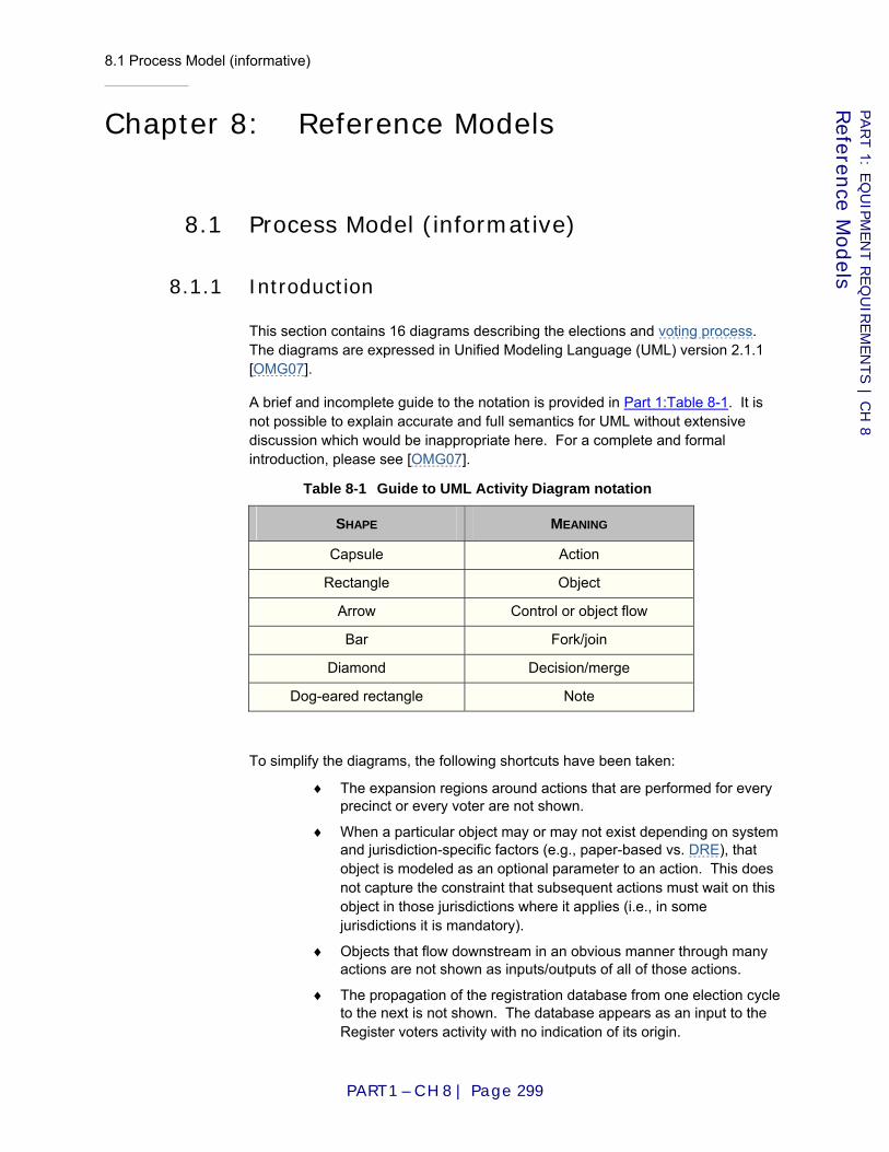
8.1 Process Model (informative)
PART 1 – CH 8 | Page 299
PART 1: E
QU
IPM
EN
T R
EQ
UIR
EM
EN
TS | C
H 8
Referen
ce Models
Chapter 8: Reference Models
8.1 Process Model (informative)
8.1.1 Introduction
This section contains 16 diagrams describing the elections and voting process. The diagrams are expressed in Unified Modeling Language (UML) version 2.1.1 [OMG07].
A brief and incomplete guide to the notation is provided in Part 1:Table 8-1. It is not possible to explain accurate and full semantics for UML without extensive discussion which would be inappropriate here. For a complete and formal introduction, please see [OMG07].
Table 8-1 Guide to UML Activity Diagram notation
SHAPE MEANING
Capsule Action
Rectangle Object
Arrow Control or object flow
Bar Fork/join
Diamond Decision/merge
Dog-eared rectangle Note
To simplify the diagrams, the following shortcuts have been taken:
♦ The expansion regions around actions that are performed for every precinct or every voter are not shown.
♦ When a particular object may or may not exist depending on system and jurisdiction-specific factors (e.g., paper-based vs. DRE), that object is modeled as an optional parameter to an action. This does not capture the constraint that subsequent actions must wait on this object in those jurisdictions where it applies (i.e., in some jurisdictions it is mandatory).
♦ Objects that flow downstream in an obvious manner through many actions are not shown as inputs/outputs of all of those actions.
♦ The propagation of the registration database from one election cycle to the next is not shown. The database appears as an input to the Register voters activity with no indication of its origin.
8.1 Process Model (informative)
PART 1 – CH 8 | Page 300
PART 1: E
QU
IPM
EN
T R
EQ
UIR
EM
EN
TS | C
H 8
Referen
ce Models
♦ Many actions produce reports and other objects that eventually flow into the Archive action. These flows into the archive are not shown.

8.1 Process Model (informative)
PART 1 – CH 8 | Page 301
PART 1: E
QU
IPM
EN
T R
EQ
UIR
EM
EN
TS | C
H 8
Referen
ce Models
8.1.2 Diagrams
Figure 8-1 Administer elections
Prepare for election
Gather absentee / remote votes
Wrap up election
Ballots, ballot images and/or machine totals
Includes early voting
Prepare for voting (central)
Wrap up voting (central)
Ballots, ballot images and/or precinct totals
Prepare for voting (precinct)
Count (precinct count)Gather in-person vote
Wrap up voting (precinct)
Counts[certified]
[Precinct count]
Equipment, voter lists, ballot styles and/or ballots
Ballots and/or ballot images Machine totals
Ballots and/or ballot images
Collect
0..1
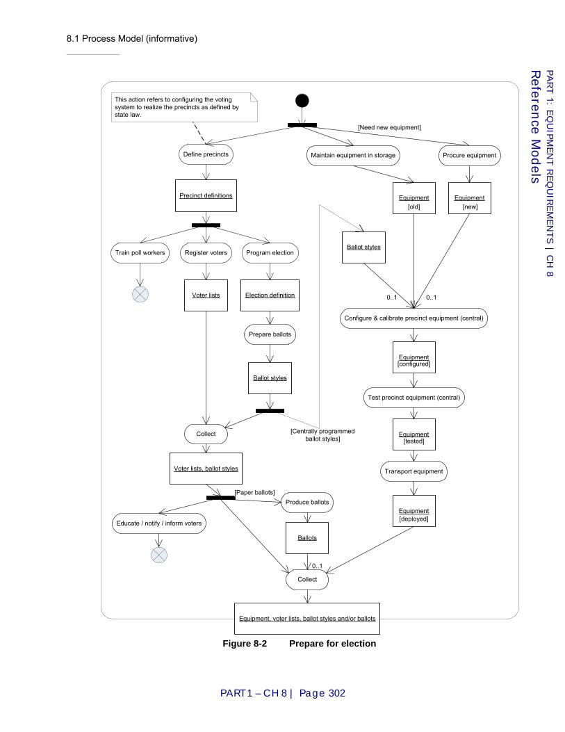
8.1 Process Model (informative)
PART 1 – CH 8 | Page 302
PART 1: E
QU
IPM
EN
T R
EQ
UIR
EM
EN
TS | C
H 8
Referen
ce Models
Figure 8-2 Prepare for election
Define precincts Maintain equipment in storage
Precinct definitions
Register voters Program election
Voter lists Election definition
Prepare ballots
Ballot styles
Produce ballots
Educate / notify / inform voters
Configure & calibrate precinct equipment (central)
Test precinct equipment (central)
Equipment[configured]
Transport equipment
Equipment[tested]
Equipment[deployed]
Ballots
[Need new equipment]
Procure equipment
Train poll workers
[Centrally programmedballot styles]
Ballot styles
This action refers to configuring the votingsystem to realize the precincts as defined bystate law.
Equipment[old]
0..1
Equipment[new]
0..1
Collect
Voter lists, ballot styles
Equipment, voter lists, ballot styles and/or ballots
Collect
[Paper ballots]
0..1

8.1 Process Model (informative)
PART 1 – CH 8 | Page 303
PART 1: E
QU
IPM
EN
T R
EQ
UIR
EM
EN
TS | C
H 8
Referen
ce Models
Figure 8-3 Gather in-person vote (paper-based)
Present credentialsCheck identity of voter
Check voter eligibility
Update poll book
Issue ballot or provisional ballot
Provide private voting station
Mark ballot
Handle abandoned ballot
[Fled voter]
Review ballot
[else]
Spoil ballot[Not OK]
Present / submit ballot
[OK]
Validate ballot
Accept ballot
[OK]
[Not OK]
[Try again]
[else]
Ballot[completed]
Ballot[blank]
Ballot[accepted]
Voter lists
Voter Poll worker /Election judge
This activity occurs once per voter.
Spoil ballot

8.1 Process Model (informative)
PART 1 – CH 8 | Page 304
PART 1: E
QU
IPM
EN
T R
EQ
UIR
EM
EN
TS | C
H 8
Referen
ce Models
Figure 8-4 Gather in-person vote (DRE)
Present credentials
Check identity of voter
Check voter eligibility
Update poll book
Provide private voting station
Mark ballot
[Fled voter]
Review ballot
[else]
[Not OK]
[OK]
Cast ballot
Ballot image
Voter lists
Voter
This activity occurs once per voter.
Correct ballot
Handle abandoned ballot
Poll worker /Election judge
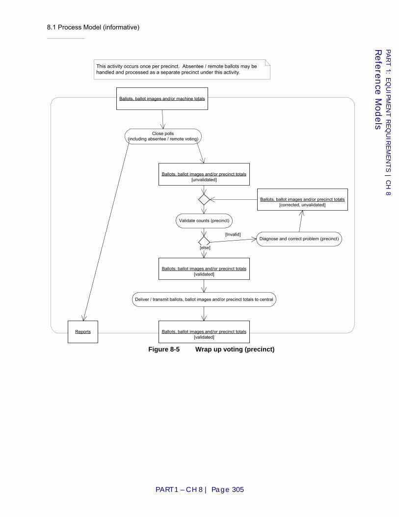
8.1 Process Model (informative)
PART 1 – CH 8 | Page 305
PART 1: E
QU
IPM
EN
T R
EQ
UIR
EM
EN
TS | C
H 8
Referen
ce Models
Figure 8-5 Wrap up voting (precinct)
Close polls(including absentee / remote voting)
Validate counts (precinct)
Ballots, ballot images and/or precinct totals[unvalidated]
Diagnose and correct problem (precinct)
Ballots, ballot images and/or precinct totals[validated]
Deliver / transmit ballots, ballot images and/or precinct totals to central
Ballots, ballot images and/or precinct totals[validated]
Reports
This activity occurs once per precinct. Absentee / remote ballots may behandled and processed as a separate precinct under this activity.
Ballots, ballot images and/or precinct totals[corrected, unvalidated]
[else]
[Invalid]
Ballots, ballot images and/or machine totals
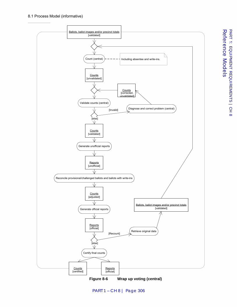
8.1 Process Model (informative)
PART 1 – CH 8 | Page 306
PART 1: E
QU
IPM
EN
T R
EQ
UIR
EM
EN
TS | C
H 8
Referen
ce Models
Figure 8-6 Wrap up voting (central)
Count (central)
Validate counts (central)
Diagnose and correct problem (central)[Invalid]
Counts[validated]
Ballots, ballot images and/or precinct totals[validated]
Generate official reports
Certify final counts
Reconcile provisional/challenged ballots and ballots with write-ins
Counts[adjusted]
Counts[unvalidated]
Counts[certified]
Generate unofficial reports
Reports[unofficial]
Including absentee and write-ins.
[else]
[else]
Counts[corrected,
unvalidated]
Retrieve original data[Recount]
Ballots, ballot images and/or precinct totals[validated]
Reports[official]
Reports[official]
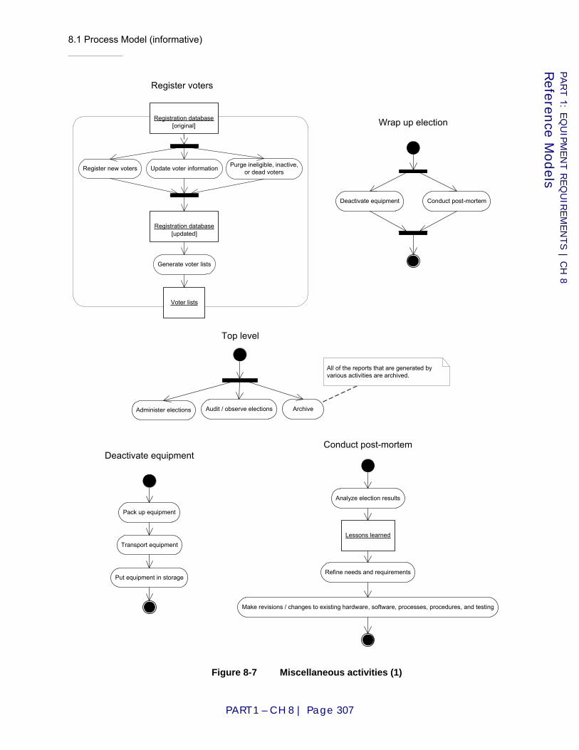
8.1 Process Model (informative)
PART 1 – CH 8 | Page 307
PART 1: E
QU
IPM
EN
T R
EQ
UIR
EM
EN
TS | C
H 8
Referen
ce Models
Figure 8-7 Miscellaneous activities (1)
Deactivate equipment
Pack up equipment
Transport equipment
Put equipment in storage
Administer elections Audit / observe elections Archive
Top level
Conduct post-mortem
Analyze election results
Lessons learned
Refine needs and requirements
Make revisions / changes to existing hardware, software, processes, procedures, and testing
Register voters
Registration database[original]
Registration database[updated]
Register new voters Purge ineligible, inactive,or dead voters
Generate voter lists
Voter lists
Update voter information
All of the reports that are generated byvarious activities are archived.
Wrap up election
Deactivate equipment Conduct post-mortem
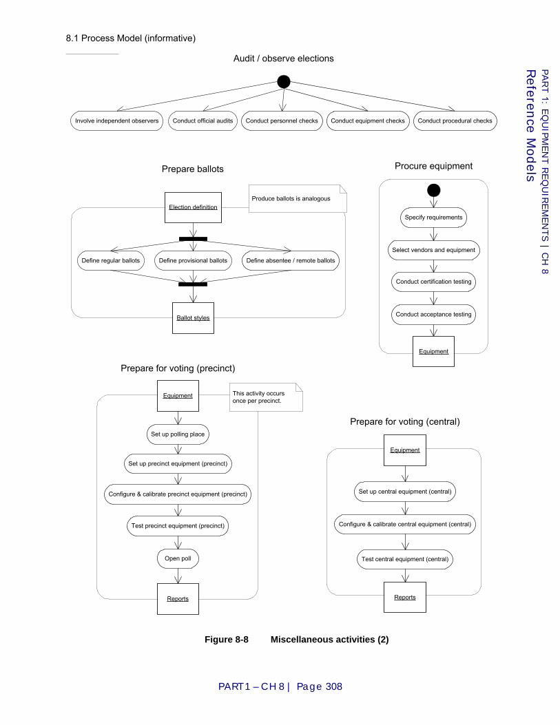
8.1 Process Model (informative)
PART 1 – CH 8 | Page 308
PART 1: E
QU
IPM
EN
T R
EQ
UIR
EM
EN
TS | C
H 8
Referen
ce Models
Figure 8-8 Miscellaneous activities (2)
Audit / observe elections
Involve independent observers Conduct equipment checksConduct personnel checksConduct official audits Conduct procedural checks
Prepare for voting (central)
Set up central equipment (central)
Configure & calibrate central equipment (central)
Test central equipment (central)
Reports
Equipment
Produce ballots is analogous
Define regular ballots Define provisional ballots Define absentee / remote ballots
Ballot styles
Prepare ballots
Election definition
Procure equipment
Specify requirements
Select vendors and equipment
Conduct certification testing
Conduct acceptance testing
Equipment
Prepare for voting (precinct)
Set up polling place
Open poll
Set up precinct equipment (precinct)
Reports
Configure & calibrate precinct equipment (precinct)
Test precinct equipment (precinct)
Equipment This activity occursonce per precinct.
8.1 Process Model (informative)
PART 1 – CH 8 | Page 309
PART 1: E
QU
IPM
EN
T R
EQ
UIR
EM
EN
TS | C
H 8
Referen
ce Models
8.1.3 Translation of diagrams
This subsection contains a rendering of the process model into text. The rendering is based on the Petri Net Linear Form [Martin07]. At the time of this writing, a full discussion of the origins and formal definition of the notation are being prepared as a NIST IR with the working title "Rendering UML Activity Diagrams as Human-Readable Text."
Although the form of the diagrams is being changed from drawings to text, the meanings of the diagram elements—actions, objects, etc.—continue to be as in UML 2.1.1 [OMG07].
Actions are represented in this translation by the action name in parenthesis. Objects are represented in this translation by the object name in square brackets. Object states are represented with annotations of the form state=x.
Sequential control and object flows are indicated with ->.
A flow may be qualified by a guard condition and/or a multiplicity such as 0..1. These notations are inserted immediately before and after the affected flow. For example, Daytime->0..1("Drink coffee") denotes an optional flow into the "drink coffee" action that can only occur if the condition Daytime is true.
A node may be assigned an identifier that may be used as the target of flows from elsewhere in the diagram. The identifier is prefixed by an asterisk and is introduced by including it after the first occurrence of the node name. For example, ("Do something" *s) denotes an action "do something" with the identifier *s. The node name may be omitted in subsequent references that include only the identifier.
The following special nodes appear with semantics as in UML 2.1.1. They are distinguished from objects and actions by being enclosed between < and >.
♦ <InitialNode>
♦ <ForkNode>
♦ <JoinNode>
♦ <DecisionNode>
♦ <MergeNode>
♦ <ActivityFinal>
♦ <FlowFinal>
When multiple flows follow from a node, they are listed between curly braces {} and separated by commas.
A semicolon indicates that the description is about to continue at a different node. A period indicates that the description of the diagram is complete.
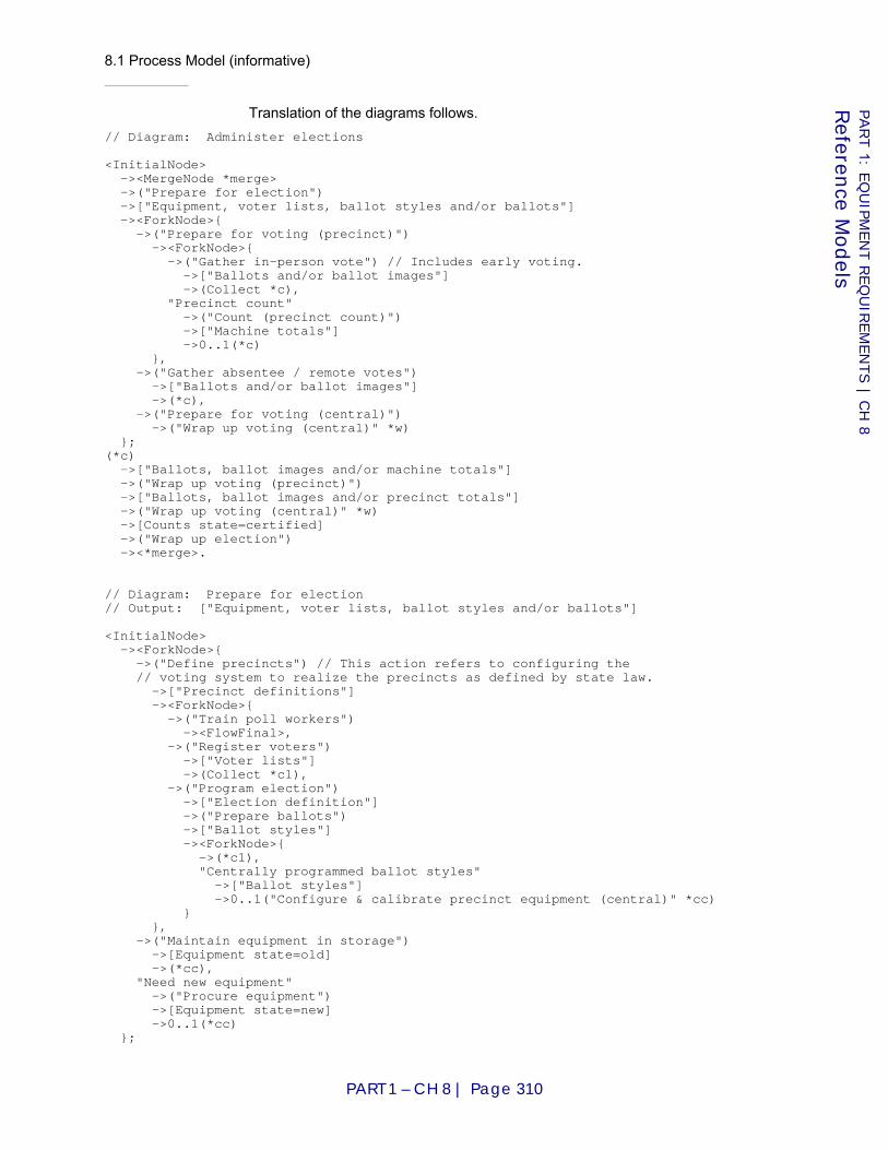
8.1 Process Model (informative)
PART 1 – CH 8 | Page 310
PART 1: E
QU
IPM
EN
T R
EQ
UIR
EM
EN
TS | C
H 8
Referen
ce Models
Translation of the diagrams follows. // Diagram: Administer elections <InitialNode> -><MergeNode *merge> ->("Prepare for election") ->["Equipment, voter lists, ballot styles and/or ballots"] -><ForkNode>{ ->("Prepare for voting (precinct)") -><ForkNode>{ ->("Gather in-person vote") // Includes early voting. ->["Ballots and/or ballot images"] ->(Collect *c), "Precinct count" ->("Count (precinct count)") ->["Machine totals"] ->0..1(*c) }, ->("Gather absentee / remote votes") ->["Ballots and/or ballot images"] ->(*c), ->("Prepare for voting (central)") ->("Wrap up voting (central)" *w) }; (*c) ->["Ballots, ballot images and/or machine totals"] ->("Wrap up voting (precinct)") ->["Ballots, ballot images and/or precinct totals"] ->("Wrap up voting (central)" *w) ->[Counts state=certified] ->("Wrap up election") -><*merge>. // Diagram: Prepare for election // Output: ["Equipment, voter lists, ballot styles and/or ballots"] <InitialNode> -><ForkNode>{ ->("Define precincts") // This action refers to configuring the // voting system to realize the precincts as defined by state law. ->["Precinct definitions"] -><ForkNode>{ ->("Train poll workers") -><FlowFinal>, ->("Register voters") ->["Voter lists"] ->(Collect *c1), ->("Program election") ->["Election definition"] ->("Prepare ballots") ->["Ballot styles"] -><ForkNode>{ ->(*c1), "Centrally programmed ballot styles" ->["Ballot styles"] ->0..1("Configure & calibrate precinct equipment (central)" *cc) } }, ->("Maintain equipment in storage") ->[Equipment state=old] ->(*cc), "Need new equipment" ->("Procure equipment") ->[Equipment state=new] ->0..1(*cc) };

8.1 Process Model (informative)
PART 1 – CH 8 | Page 311
PART 1: E
QU
IPM
EN
T R
EQ
UIR
EM
EN
TS | C
H 8
Referen
ce Models
(*c1) ->["Voter lists, ballot styles"] -><ForkNode>{ ->("Educate / notify / inform voters") -><FlowFinal>, ->(Collect *c2), "Paper ballots" ->("Produce ballots") ->[Ballots] ->0..1(*c2) }; (*cc) ->[Equipment state=configured] ->("Test precinct equipment (central)") ->[Equipment state=tested] ->("Transport equipment") ->[Equipment state=deployed] ->(Collect *c2) ->["Equipment, voter lists, ballot styles and/or ballots"]. // Diagram: Gather in-person vote (paper-based). // // This diagram is divided to show which actions are done by the voter // and which are done by the poll worker or election judge. The action // Spoil ballot may be done by either. Present credentials, Mark ballot, // Review ballot, and Present / submit ballot are done by the voter. All // others are done by the poll worker or election judge. // // Note: This activity occurs once per voter. // // Input: ["Voter lists"] // Output: [Ballot state=accepted] ["Voter lists"] ->("Check identity of voter" *check); <InitialNode> ->("Present credentials") ->("Check identity of voter" *check) ->("Check voter eligibility") -><MergeNode *merge> ->("Update poll book") ->("Issue ballot or provisional ballot") ->("Provide private voting station") ->[Ballot state=blank] ->("Mark ballot") -><DecisionNode>{ "Fled voter" ->("Handle abandoned ballot") -><ActivityFinal>, else ->("Review ballot") -><DecisionNode>{ "Not OK" ->("Spoil ballot") -><*merge>, OK ->("Present / submit ballot") ->[Ballot state=completed] ->("Validate ballot") -><DecisionNode>{ OK ->("Accept ballot") ->[Ballot state=accepted], "Not OK" ->("Spoil ballot") -><DecisionNode>{

8.1 Process Model (informative)
PART 1 – CH 8 | Page 312
PART 1: E
QU
IPM
EN
T R
EQ
UIR
EM
EN
TS | C
H 8
Referen
ce Models
"Try again" -><*merge>, else -><ActivityFinal> } } } }. // Diagram: Gather in-person vote (DRE). // // This diagram is divided to show which actions are done by the voter // and which are done by the poll worker or election judge. Present // credentials, Mark ballot, Review ballot, Correct ballot, and Cast // ballot are done by the voter. All others are done by the poll worker // or election judge. // // Note: This activity occurs once per voter. // // Input: ["Voter lists"] // Output: ["Ballot image"] ["Voter lists"] ->("Check identity of voter" *check); <InitialNode> ->("Present credentials") ->("Check identity of voter" *check) ->("Check voter eligibility") ->("Update poll book") ->("Provide private voting station") ->("Mark ballot") -><MergeNode *merge> -><DecisionNode>{ "Fled voter" ->("Handle abandoned ballot") -><ActivityFinal>, else ->("Review ballot") -><DecisionNode>{ "Not OK" ->("Correct ballot") -><*merge>, OK ->("Cast ballot") ->["Ballot image"] } }. // Diagram: Wrap up voting (precinct) // // Note: This activity occurs once per precinct. Absentee / remote // ballots may be handled and processed as a separate precinct under this // activity. // // Input: ["Ballots, ballot images and/or machine totals"] // Outputs: [Reports], ["Ballots, ballot images and/or precinct totals" state=validated] ["Ballots, ballot images and/or machine totals"] ->("Close polls (including absentee / remote voting)"){ ->[Reports], ->["Ballots, ballot images and/or precinct totals" state=unvalidated] -><MergeNode *merge> ->("Validate counts (precinct)") -><DecisionNode>{

8.1 Process Model (informative)
PART 1 – CH 8 | Page 313
PART 1: E
QU
IPM
EN
T R
EQ
UIR
EM
EN
TS | C
H 8
Referen
ce Models
Invalid ->("Diagnose and correct problem (precinct)") ->["Ballots, ballot images and/or precinct totals" state="corrected, unvalidated"] -><*merge>, else ->["Ballots, ballot images and/or precinct totals" state=validated] ->("Deliver / transmit ballots, ballot images and/or precinct totals to central") ->["Ballots, ballot images and/or precinct totals" state=validated] } }. // Diagram: Wrap up voting (central) // // Input: ["Ballots, ballot images and/or precinct totals" state=validated] // Outputs: [Counts state=certified], [Reports state=official] ["Ballots, ballot images and/or precinct totals" state=validated] -><MergeNode *merge1> ->("Count (central)") // Including absentee and write-ins. ->[Counts state=unvalidated] -><MergeNode *merge2> ->("Validate counts (central)") -><DecisionNode>{ Invalid ->("Diagnose and correct problem (central)") ->[Counts state="corrected, unvalidated"] -><*merge2>, else ->[Counts state=validated] ->("Generate unofficial reports") ->[Reports state=unofficial] ->("Reconcile provisional/challenged ballots and ballots with write-ins") ->[Counts state=adjusted] ->("Generate official reports") ->[Reports state=official] -><DecisionNode>{ Recount ->("Retrieve original data") ->["Ballots, ballot images and/or precinct totals" state=validated] -><*merge1>, else ->("Certify final counts"){ ->[Counts state=certified], ->[Reports state=official] } } }. // Diagram: Audit / observe elections <InitialNode>{ ->("Involve independent observers"), ->("Conduct official audits"), ->("Conduct personnel checks"), ->("Conduct equipment checks"), ->("Conduct procedural checks") }. // Diagram: Prepare ballots // // Note: Produce ballots is analogous. //
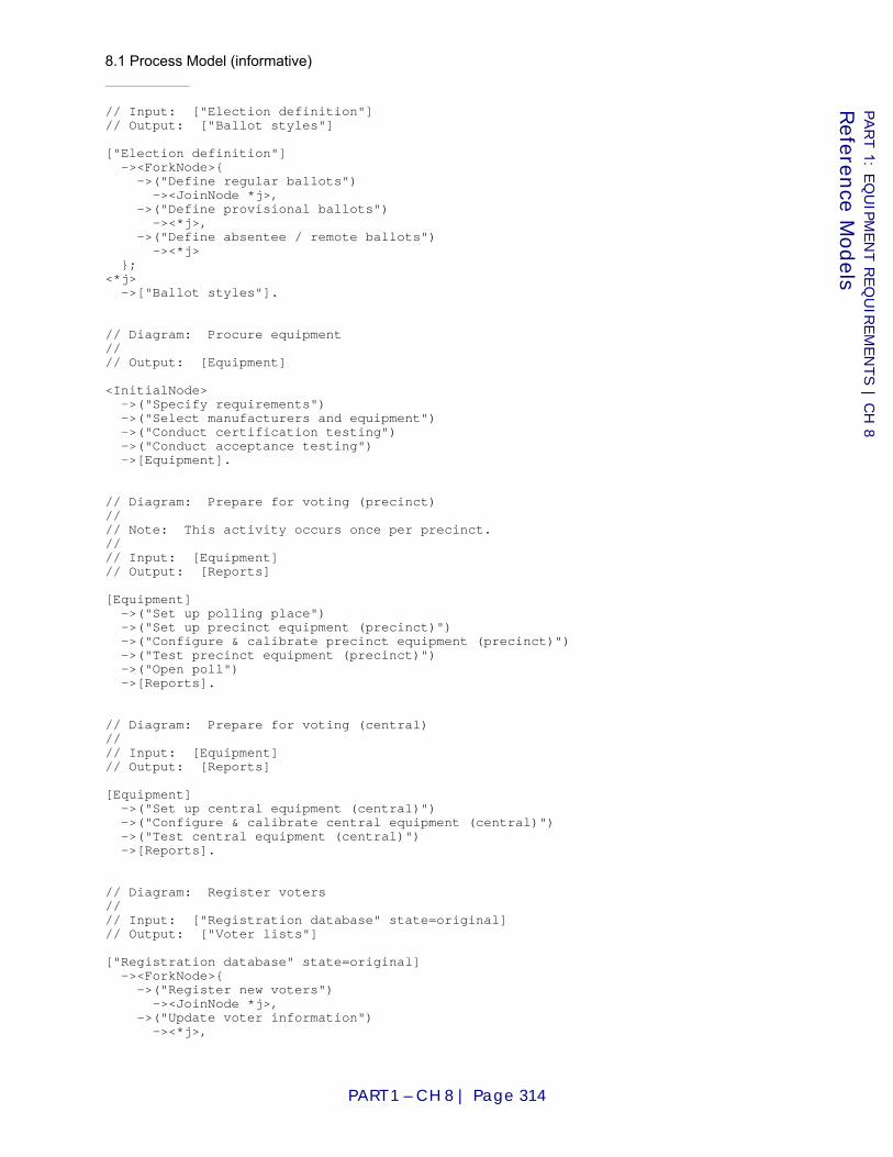
8.1 Process Model (informative)
PART 1 – CH 8 | Page 314
PART 1: E
QU
IPM
EN
T R
EQ
UIR
EM
EN
TS | C
H 8
Referen
ce Models
// Input: ["Election definition"] // Output: ["Ballot styles"] ["Election definition"] -><ForkNode>{ ->("Define regular ballots") -><JoinNode *j>, ->("Define provisional ballots") -><*j>, ->("Define absentee / remote ballots") -><*j> }; <*j> ->["Ballot styles"]. // Diagram: Procure equipment // // Output: [Equipment] <InitialNode> ->("Specify requirements") ->("Select manufacturers and equipment") ->("Conduct certification testing") ->("Conduct acceptance testing") ->[Equipment]. // Diagram: Prepare for voting (precinct) // // Note: This activity occurs once per precinct. // // Input: [Equipment] // Output: [Reports] [Equipment] ->("Set up polling place") ->("Set up precinct equipment (precinct)") ->("Configure & calibrate precinct equipment (precinct)") ->("Test precinct equipment (precinct)") ->("Open poll") ->[Reports]. // Diagram: Prepare for voting (central) // // Input: [Equipment] // Output: [Reports] [Equipment] ->("Set up central equipment (central)") ->("Configure & calibrate central equipment (central)") ->("Test central equipment (central)") ->[Reports]. // Diagram: Register voters // // Input: ["Registration database" state=original] // Output: ["Voter lists"] ["Registration database" state=original] -><ForkNode>{ ->("Register new voters") -><JoinNode *j>, ->("Update voter information") -><*j>,
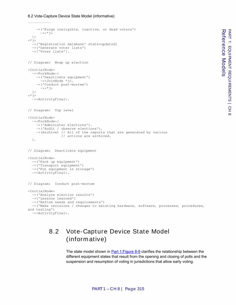
8.2 Vote-Capture Device State Model (informative)
PART 1 – CH 8 | Page 315
PART 1: E
QU
IPM
EN
T R
EQ
UIR
EM
EN
TS | C
H 8
Referen
ce Models
->("Purge ineligible, inactive, or dead voters") -><*j> }; <*j> ->["Registration database" state=updated] ->("Generate voter lists") ->["Voter lists"]. // Diagram: Wrap up election <InitialNode> -><ForkNode>{ ->("Deactivate equipment") -><JoinNode *j>, ->("Conduct post-mortem") -><*j> }; <*j> -><ActivityFinal>. // Diagram: Top level <InitialNode> -><ForkNode>{ ->("Administer elections"), ->("Audit / observe elections"), ->(Archive) // All of the reports that are generated by various // actions are archived. }. // Diagram: Deactivate equipment <InitialNode> ->("Pack up equipment") ->("Transport equipment") ->("Put equipment in storage") -><ActivityFinal>. // Diagram: Conduct post-mortem <InitialNode> ->("Analyze election results") ->["Lessons learned"] ->("Refine needs and requirements") ->("Make revisions / changes to existing hardware, software, processes, procedures, and testing") -><ActivityFinal>.
8.2 Vote-Capture Device State Model (informative)
The state model shown in Part 1:Figure 8-9 clarifies the relationship between the different equipment states that result from the opening and closing of polls and the suspension and resumption of voting in jurisdictions that allow early voting.

8.3 Logic Model (normative)
PART 1 – CH 8 | Page 316
PART 1: E
QU
IPM
EN
T R
EQ
UIR
EM
EN
TS | C
H 8
Referen
ce Models
Figure 8-9 Vote-capture device states
The many steps that occur prior to the opening of polls are abstracted by the Pre-voting state. The many steps that occur after the close of polls are abstracted by the Post-voting state. Between these is a composite state Open, which contains the simple state Suspended and the composite state Activated. Activated in turn contains the simple states Ready and In use.
Upon the opening of polls, the vote-capture device transitions from the Pre-voting state to the Ready state (and, consequently, also to the Open and Activated composite states that contain it). From Ready it can transition to the In use state upon the activation of a ballot and return to the Ready state when that ballot is printed, cast or spoiled (the details depend on the technology in use). From Ready it can also transition to the Suspended state when an election official suspends voting and return to the Ready state when voting is resumed. Finally, from Ready it can transition to the Post-voting state when polls are closed.
In conformance with Requirement Part 1:7.6-B.5, there is no transition from Post-voting back to Open except by beginning an entirely new election cycle, which is not modeled here.
A voting session lasts while the device is in the In use state. An active period lasts while the device is in the Activated state.
8.3 Logic Model (normative)
This model defines the results that must appear in vote data reports and is used in verification of voting system logic. It does not address ranked order voting and does not attempt to define every voting variation that jurisdictions may use. It suffices for N-of-M (including 1-of-M) and cumulative voting.[10]
Openpolls
Pre-voting
Open
Post-voting
Closepolls
Suspended
Ready
Suspend Resume
In useActivateballot
Print/cast/spoil ballot
Activated
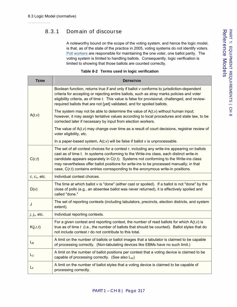
8.3 Logic Model (normative)
PART 1 – CH 8 | Page 317
PART 1: E
QU
IPM
EN
T R
EQ
UIR
EM
EN
TS | C
H 8
Referen
ce Models
8.3.1 Domain of discourse
A noteworthy bound on the scope of the voting system, and hence the logic model, is that, as of the state of the practice in 2005, voting systems do not identify voters. Poll workers are responsible for maintaining the one voter, one ballot parity. The voting system is limited to handling ballots. Consequently, logic verification is limited to showing that those ballots are counted correctly.
Table 8-2 Terms used in logic verification
TERM DEFINITION
A(t,v)
Boolean function, returns true if and only if ballot v conforms to jurisdiction-dependent criteria for accepting or rejecting entire ballots, such as stray marks policies and voter eligibility criteria, as of time t. This value is false for provisional, challenged, and review-required ballots that are not [yet] validated, and for spoiled ballots.
The system may not be able to determine the value of A(t,v) without human input; however, it may assign tentative values according to local procedures and state law, to be corrected later if necessary by input from election workers.
The value of A(t,v) may change over time as a result of court decisions, registrar review of voter eligibility, etc.
In a paper-based system, A(t,v) will be false if ballot v is unprocessable.
C(r,t)
The set of all contest choices for a contest r, including any write-ins appearing on ballots cast as of time t. In systems conforming to the Write-ins class, each distinct write-in candidate appears separately in C(r,t). Systems not conforming to the Write-ins class may nevertheless offer ballot positions for write-ins to be processed manually; in that case, C(r,t) contains entries corresponding to the anonymous write-in positions.
c, cn, etc. Individual contest choices.
D(v) The time at which ballot v is "done" (either cast or spoiled). If a ballot is not "done" by the close of polls (e.g., an absentee ballot was never returned), it is effectively spoiled and called "done."
J The set of reporting contexts (including tabulators, precincts, election districts, and system extent).
j, jn, etc. Individual reporting contexts.
K(j,r,t) For a given contest and reporting context, the number of read ballots for which A(t,v) is true as of time t (i.e., the number of ballots that should be counted). Ballot styles that do not include contest r do not contribute to this total.
LB A limit on the number of ballots or ballot images that a tabulator is claimed to be capable of processing correctly. (Non-tabulating devices like EBMs have no such limit.)
LC A limit on the number of ballot positions per contest that a voting device is claimed to be capable of processing correctly. (See also LW)
LF A limit on the number of ballot styles that a voting device is claimed to be capable of processing correctly.
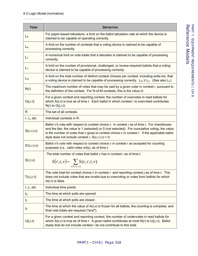
8.3 Logic Model (normative)
PART 1 – CH 8 | Page 318
PART 1: E
QU
IPM
EN
T R
EQ
UIR
EM
EN
TS | C
H 8
Referen
ce Models
TERM DEFINITION
LP For paper-based tabulators, a limit on the ballot tabulation rate at which the device is claimed to be capable of operating correctly.
LR A limit on the number of contests that a voting device is claimed to be capable of processing correctly.
LT A numerical limit on vote totals that a tabulator is claimed to be capable of processing correctly.
LV A limit on the number of provisional, challenged, or review-required ballots that a voting device is claimed to be capable of processing correctly.
LW A limit on the total number of distinct contest choices per contest, including write-ins, that a voting device is claimed to be capable of processing correctly. LW ≥ LC. (See also LC)
N(r) The maximum number of votes that may be cast by a given voter in contest r, pursuant to the definition of the contest. For N-of-M contests, this is the value N.
O(j,r,t) For a given contest and reporting context, the number of overvotes in read ballots for which A(t,v) is true as of time t. Each ballot in which contest r is overvoted contributes N(r) to O(j,r,t).
R The set of all contests.
r, rn, etc. Individual contests in R.
S(c,r,t,v)
Ballot v's vote with respect to contest choice c in contest r as of time t. For checkboxes and the like, the value is 1 (selected) or 0 (not selected). For cumulative voting, the value is the number of votes that v gives to contest choice c in contest r. If the applicable ballot style does not include contest r, S(c,r,t,v) = 0.
S'(c,r,t,v) Ballot v's vote with respect to contest choice c in contest r as accepted for counting purposes (i.e., valid votes only), as of time t.
S(r,t,v)
The total number of votes that ballot v has in contest r as of time t.
T(c,j,r,t) The vote total for contest choice c in contest r and reporting context j as of time t. This does not include votes that are invalid due to overvoting or votes from ballots for which A(t,v) is false.
t, tn, etc. Individual time points.
tO The time at which polls are opened.
tC The time at which polls are closed.
tE The time at which the value of A(t,v) is frozen for all ballots, the counting is complete, and final vote totals are required ("end").
U(j,r,t) For a given contest and reporting context, the number of undervotes in read ballots for which A(t,v) is true as of time t. A given ballot contributes at most N(r) to U(j,r,t). Ballot styles that do not include contest r do not contribute to this total.
( ) ∑∈
=),(
),,,(,,trCc
vtrcSvtrS

8.3 Logic Model (normative)
PART 1 – CH 8 | Page 319
PART 1: E
QU
IPM
EN
T R
EQ
UIR
EM
EN
TS | C
H 8
Referen
ce Models
TERM DEFINITION
V(j,t)
The set of all ballots that have been distributed to voters, enabled, activated or issued within reporting context j by time t, including any that are presently being voted. Absentee ballots, provisional/challenged ballots, and review-required ballots are included in V if and only if the system claims conformance to the relevant classes. Ballots containing write-in votes may be included for systems not conforming to the Write-ins class if the system reports all write-in votes as a single ballot position. For more information on this exception see C(r,t) and Part 1:2.5.3.1 “Supported voting variations (system-level)”.
v, vn, etc. Individual ballots in V(j,t).
Ballot styles, which determine which contests appear on a given ballot, are factored out of this model. They impact it only indirectly—see the definitions of K(j,r,t), S(c,r,t,v), and U(j,r,t).
8.3.2 General constraints
Invariants:
The following formalize several basic integrity constraints. Each textual description is intended to elucidate the formal constraint(s) that follow it. In case of discrepancy or confusion, the formal constraints are normative.
No ballots will be accepted before polls are opened or after polls have closed, or during the process of opening or closing the polls (N.B., in early voting, polls are considered open when vote collection begins; see Part 1:8.2 “Vote-Capture Device State Model (informative)”.):
No votes will be counted until after polls are opened:
All tallies must remain zero until after polls are opened:
A CVR cannot change once the voting session for that ballot has ended:
( ) CO tvDt <<
( ) 0,,,' =→≤ vtrcStt O
( ) 0,,, =→≤ trjcTtt O
( ) ( ) ( )( )vvDrcSvtrcSvDt ,,,,,, =→≥
( ) 0,,, ≥vtrcS
( ) 0,,,' ≥vtrcS
ECO ttt ≤<
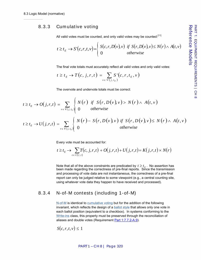
8.3 Logic Model (normative)
PART 1 – CH 8 | Page 320
PART 1: E
QU
IPM
EN
T R
EQ
UIR
EM
EN
TS | C
H 8
Referen
ce Models
8.3.3 Cumulative voting
All valid votes must be counted, and only valid votes may be counted:[11]
The final vote totals must accurately reflect all valid votes and only valid votes:
The overvote and undervote totals must be correct:
Every vote must be accounted for:
Note that all of the above constraints are predicated by Ett ≥ . No assertion has been made regarding the correctness of pre-final reports. Since the transmission and processing of vote data are not instantaneous, the correctness of a pre-final report can only be judged relative to some viewpoint (e.g., a central counting site, using whatever vote data they happen to have received and processed).
8.3.4 N-of-M contests (including 1-of-M)
N-of-M is identical to cumulative voting but for the addition of the following invariant, which reflects the design of a ballot style that allows only one vote in each ballot position (equivalent to a checkbox). In systems conforming to the Write-ins class, this property must be preserved through the reconciliation of aliases and double votes (Requirement Part 1:7.7.2-A.9).
( ) 1,,, ≤vtrcS
( ) =→≥ vtrcStt E ,,,' ( )( ) ( )( ) ( ) ( )vtArNvvDrSifvvDrcS ,,,,,, ∧≤otherwise0{
( ) ( )( )∑
∈
=→≥EtjVv
EE vtrcStrjcTtt,
,,,',,,
( )( )∑
∈
=→≥EtjVv
E trjOtt,
,, ( ) ( )( ) ( ) ( )vtArNvvDrSifrN ,,, ∧>otherwise0{
( )( )∑
∈
=→≥EtjVv
E trjUtt,
,,( ) ( )( ) ( )( ) ( ) ( )vtArNvvDrSifvvDrSrN ,,,,, ∧≤−
otherwise0{( ) ( ) ( ) ( ) ( )
( )∑
∈
×=++→≥trCc
E rNtrjKtrjUtrjOtrjcTtt,
,,,,,,,,,
VVSG Recommenda t i ons
t o t he EAC
P A R T 2 :
Documentation Requirements
Prepared at the Direction of the
Technical Guidelines Development Committee
August 2007


PART 2 – CH 1 | Page 1
Part 2: Documentation Requirements
Chapter 1: Introduction
This part of the VVSG, Documentation Requirements, contains requirements applying to the Technical Data Package, the Voting Equipment User Documentation, the Test Plan, the Test Report, the Public Information Package, and the data for repositories. It is intended primarily for use by manufacturers, test labs, and software repositories.
This part contains 7 chapters, organized as follows:
♦ Chapter 2: manufacturer requirements for quality assurance and configuration management documentation provided to test labs;
♦ Chapter 3: manufacturer requirements for documentation to be included in the technical data package provided to test labs;
♦ Chapter 4: manufacturer requirements for documentation provided to users, i.e., customers;
♦ Chapter 5: requirements for the voting system test plan, provided by the test lab;
♦ Chapter 6: requirements for the test report provided by the test lab; and
♦ Chapter 7: requirements for test results-related documentation to be made available to the public.
NOTE: Requirements in Part 2 do not contain “Test Reference:” fields. All requirements in Part 2, unless otherwise specified, are assumed to be tested by Part 3:Chapter 4: ”Documentation and Design Reviews (Inspections)”.
1.1 Changes from VVSG 2005 and Previous Versions of the Standards
As part of the overall cleanup of the Guidelines, requirements to document certain things or to provide certain information have been moved into a separate part from functional and performance requirements applying to the voting equipment itself.
1.1 Changes from VVSG 2005 and Previous Versions of the Standards
PART 2 – CH 1 | Page 2
PART 2: D
OCU
MEN
TATIO
N R
EQ
UIR
EM
EN
TS | C
H 1
Intro
ductio
n
1.1.1 Separation of requirements on Voting Equipment User Documentation from requirements on Technical Data Package
In previous Guidelines, there were requirements saying such things as "Provide documentation," "The vendor shall document," "The vendor shall provide detailed descriptions of," or "Documentation shall include" with no indication of whether said documentation should be available to all users (in the Voting Equipment User Documentation) or merely to the test lab (in the Technical Data Package). These Guidelines have clarified which is which.
A copy of the Voting Equipment User Documentation is included in the TDP.
1.1.2 Changes in TDP content
Technical Data Package requirements have been modified to enable verification of voting application logic implemented in software, firmware, and hardware (see Part 3:4.6 “Logic Verification”) and to clarify source code requirements in boundary cases. Operating systems that are customized or that implement application-level voting logic are subject to a source code review.
Numerous changes in wording have been made to clarify the requirements that were carried over from previous Guidelines.
1.1.3 Revisions to test lab reports
The Certification Test Plan and Test Report described in [VVSG2005] required revision to deal with the evolution of certification testing to include standard test methods and an expanded scope of testing.
The chapters on the Certification Test Plan and Test Report have been changed from complete, but informative, outlines of the reports to minimal, but normative, sets of requirements on what the test reports must contain. Test labs are now encouraged to apply relevant external standards, such as [IEEE95] and [IEEE98], to determine the organization and content of test plans, provided that the information described in Part 2:Chapter 5: “Test Plan (test lab)” does appear in the result.
1.1.4 Public Information Package (PIP)
Public assurance that the voting system is fit for use can occur vicariously, through trust in the test lab and election officials; indirectly, through verification that the certification process was responsibly executed; directly, through election verification; or through a combination of these.

1.1 Changes from VVSG 2005 and Previous Versions of the Standards
PART 2 – CH 1 | Page 3
PART 2: D
OCU
MEN
TATIO
N R
EQ
UIR
EM
EN
TS | C
H 1
Intro
ductio
n
A "Public Information Package" that must be publicly available and published as evidence that the certification process was responsibly executed now appears in Part 2:Chapter 7: “Public Information Package (test lab)”.
The same minimal requirements apply to the PIP as apply to the test report, and the same minimal requirements apply to the test plan contained in the PIP as apply to the test plan contained in the test report. The difference is that the test report for the certification authority may contain additional, manufacturer-proprietary information that would not be suitable for publication.

1.1 Changes from VVSG 2005 and Previous Versions of the Standards
PART 2 – CH 1 | Page 4
PART 2: D
OCU
MEN
TATIO
N R
EQ
UIR
EM
EN
TS | C
H 1
Intro
ductio
n

2.1 Quality and Configuration Management Manual
PART 2 – CH 2 | Page 5
PART 2: D
OCU
MEN
TATIO
N R
EQ
UIR
EM
EN
TS | C
H 2
Quality A
ssuran
ce and C
onfig
uratio
n M
anag
emen
t Data Packag
e (man
ufactu
rer)
Chapter 2: Quality Assurance and Configuration Management Data Package (manufacturer)
This section contains requirements on the content of the quality assurance and configuration management documentation that manufacturers must supply to the certification authority.
2.1 Quality and Configuration Management Manual
2.1-A Develop and present
All voting system manufacturers SHALL develop and present to the certification authority a complete Quality and Configuration Management Manual.
Applies to: Voting system
Source: New requirement
2.1-A.1 Processes and procedures
The Manual SHALL detail the manufacturer's Quality Assurance and Configuration Management processes and procedures required by the VVSG. These processes and procedures SHALL conform to all requirements of the VVSG and the standards listed in Requirement Part 1:6.4.2.1-A.
Applies to: Voting system
Source: New requirement
2.1-A.2 A binding commitment
The Manual SHALL declare that meeting the requirements of the entire VVSG is a binding commitment for the entire manufacturer organization.
Applies to: Voting system
Source: New requirement

2.1 Quality and Configuration Management Manual
PART 2 – CH 2 | Page 6
PART 2: D
OCU
MEN
TATIO
N R
EQ
UIR
EM
EN
TS | C
H 2
Quality A
ssuran
ce and C
onfig
uratio
n M
anag
emen
t Data Packag
e (man
ufactu
rer)
2.1-A.3 Project plan
The Manual SHALL provide for the formulation of a project plan for the design and development of a voting system. It SHALL require the project plan to be clearly and unambiguously documented.
Applies to: Voting system
D I S C U S S I O N
The project plan should be consistent with the Design and Development Planning requirements, as specified in ISO 9001:2000, Quality management systems – Requirements [ISO00] Section 8.3.1.
Source: New requirement
2.1-A.4 Quality check
The Manual SHALL require the project plan to include, at a minimum, one quality check at the end of the design phase, and one quality check at the end of the development phase. The project plan SHALL define the progress that is required before each quality check can be passed.
Applies to: Voting system
D I S C U S S I O N
A "quality check" is the sum of the activities Design and Development Review, Design and Development Verification, and Design and Development Validation, as defined in [ISO00] Sections 7.3.4. through 7.3.6.
Source: New requirement
2.1-A.5 Problem log
The Manual SHALL require the manufacturer to maintain a log in which all difficulties encountered during the design and development phase for a voting system are required to be recorded. Any remedial action taken to correct a difficulty SHALL also be recorded. The log SHALL be available for inspection by the test lab.
Applies to: Voting system
D I S C U S S I O N
"Difficulties" are any occasions when it is recognized that changes in past design decisions or in the project plan (see Requirement Part 2:2.1-A.3) are necessary to complete the project.
Source: New requirement
2.1-A.6 Critical parts, components, and assemblies
The Manual SHALL specify rules that define what parts, components, and assemblies of the voting system are to be considered as critical. A part, component, or assembly SHALL be defined as critical if its failure may:

2.1 Quality and Configuration Management Manual
PART 2 – CH 2 | Page 7
PART 2: D
OCU
MEN
TATIO
N R
EQ
UIR
EM
EN
TS | C
H 2
Quality A
ssuran
ce and C
onfig
uratio
n M
anag
emen
t Data Packag
e (man
ufactu
rer)
a. Cause a faulty display of options; b. Cause an uncertainty if voter's choice has been recorded; c. Cause a false recording of vote cast; d. Cause the change of stored votes; e. Cause the false transmission for polling station totals; f. Cause injury to voters or staff; g. Provide an opening for tampering; h. Violate a voter's privacy; i. Cause a false accumulation of polling station totals; j. Cause a false transmission for regional totals; k. Give the appearance of irregularity; l. Violate a voter's ability to vote independently; and m. Impede the usability of the polling station for all voters.
As used here, "components" include software modules.
Applies to: Voting system
Source: New requirement
2.1-A.7 Testing statements for every part, component, and assembly
The Manual SHALL require that the design and development process of a voting system produce statements for every part, component, and assembly, whether to be manufactured by the manufacturer or obtained elsewhere, that impacts conformity to the VVSG. These statements SHALL define verifiable requirements against which the part, component, or assembly can be tested at the end of its manufacturing process, or upon delivery, as appropriate. The requirements SHALL be defined in such a way that any part, component, or assembly that meets the requirements will provide the functionality and reliability required of it for the voting system to meet the overall functionality and reliability requirements specified in the VVSG.
Applies to: Voting system
Source: New requirement
2.1-A.8 Inspection processes for every part, component, and assembly
The Manual SHALL require that the design and development process define or identify processes by which all parts, components, and assemblies of a voting system can be tested for compliance with requirements developed under Requirement Part 2:2.1-A.7.
Applies to: Voting system
Source: New requirement
2.1-A.9 Testing statements for the entire voting system
The Manual SHALL require that the design and development process of a voting system produce a statement that defines verifiable requirements against which any voting system can be tested at the end of its

2.1 Quality and Configuration Management Manual
PART 2 – CH 2 | Page 8
PART 2: D
OCU
MEN
TATIO
N R
EQ
UIR
EM
EN
TS | C
H 2
Quality A
ssuran
ce and C
onfig
uratio
n M
anag
emen
t Data Packag
e (man
ufactu
rer)
manufacturing and assembly process in such a way that passing the test provides assurance that the voting system meets all requirements defined in the VVSG.
Applies to: Voting system
Source: New requirement
2.1-A.10 Inspection of all purchased parts, components, and assemblies
The Manual SHALL require that all purchased parts, components and assemblies are tested according to the testing requirements developed under Requirement Part 2:2.1-A.7 and the processes developed under Requirement Part 2:2.1-A.8 before they are incorporated into a voting system. The records SHALL be maintained until such time as the certification of the voting system model expires or is revoked.
Applies to: Voting system
Source: New requirement
2.1-A.11 Inspection of all manufactured parts, components, and assemblies
The Manual SHALL require that all manufactured parts, components, and assemblies are tested according to the testing requirements developed under Requirement Part 2:2.1-A.7 and the processes developed under Requirement Part 2:2.1-A.8 before they are incorporated into a voting system. The records SHALL be maintained until such time as the certification of the voting system model expires or is revoked.
Applies to: Voting system
Source: New requirement
2.1-A.12 Records of all critical parts, components, and assemblies
The Manual SHALL require that for each part, component, or assembly, whether purchased or manufactured by the manufacturer, that has been defined as critical (Requirement Part 2:2.1-A.6), records SHALL be kept that document the complete history of the part, component, or assembly. The records SHALL include:
a. The source of raw materials; b. The processes used in the manufacture; c. The time when critical manufacturing steps were taken; d. The organization or person that performed each critical
manufacturing step, and e. The persons who performed the required inspections.
The records SHALL also include documentation of: f. Any failures, discrepancies or anomalies that might have occurred
during manufacture; g. Any actions taken to correct the failure, discrepancy or anomaly; and h. The final determination that the problem has been corrected.
2.1 Quality and Configuration Management Manual
PART 2 – CH 2 | Page 9
PART 2: D
OCU
MEN
TATIO
N R
EQ
UIR
EM
EN
TS | C
H 2
Quality A
ssuran
ce and C
onfig
uratio
n M
anag
emen
t Data Packag
e (man
ufactu
rer)
These records SHALL be available for inspection.
Applies to: Voting system
Source: New requirement
2.1-A.13 Technical capability for monitoring
The Manual SHALL require the manufacturer to identify and maintain the technical capability to monitor the in-service performance of each voting system sold throughout the life cycle of the voting system's model.
Applies to: Voting system
D I S C U S S I O N
For the purpose of this and subsequent requirements in this section, the term life cycle of a voting system model is defined as the time period from the delivery of the first voting system of that model to the time when the certification of the model expires or is revoked.
Source: New requirement
2.1-A.14 Technical capability for developing and implementing remedies
The Manual SHALL require the manufacturer to identify and maintain the technical capability to develop and implement remedies that are suitable to correct any defects that lead to in-service difficulties in all voting systems sold, throughout the life cycle of the voting system model.
Applies to: Voting system
Source: New requirement
2.1-A.15 Financial capability to provide the product support
The Manual SHALL require the manufacturer to identify and maintain the financial capability to provide product support, as defined in Requirements Part 2:2.1-A.13 and Part 2:2.1-A.14, throughout the life cycle of the voting system model.
Applies to: Voting system
Source: New requirement

2.1 Quality and Configuration Management Manual
PART 2 – CH 2 | Page 10
PART 2: D
OCU
MEN
TATIO
N R
EQ
UIR
EM
EN
TS | C
H 2
Quality A
ssuran
ce and C
onfig
uratio
n M
anag
emen
t Data Packag
e (man
ufactu
rer)
3.1 Scope
PART 2 – CH 3 | Page 11
PART 2: D
OCU
MEN
TATIO
N R
EQ
UIR
EM
EN
TS | C
H 3
Tech
nical D
ata Package (m
anufactu
rer)
Chapter 3: Technical Data Package (manufacturer)
3.1 Scope
This section contains a description of manufacturer documentation relating to the voting system that must be submitted with the system as a precondition of conformity assessment. These items are necessary to define the product and its method of operation; to provide technical and test data supporting the manufacturer's claims of the system's functional capabilities and performance levels; and to document instructions and procedures governing system operation and field maintenance. Any other items relevant to the system evaluation, such as media, materials, source code, object code, and sample output report formats, must be submitted along with this documentation.
This documentation is used by the test lab in constructing the test plan. Testing of systems submitted by manufacturers that consistently adhere to particularly strong and well-documented quality assurance and configuration management practices will generally be more efficient than for systems developed and maintained using less rigorous or less well-documented practices.
Both formal documentation and notes of the manufacturer's system development process must be submitted for conformity assessment. Documentation describing the system development process permits assessment of the manufacturer's systematic efforts to develop and test the system and correct defects. Inspection of this process also enables the design of a more precise test plan. The accredited test lab must design and conduct the appropriate tests to cover all elements of the system and to ensure conformance with all system requirements.
3.1.1 Content and format
The content of the Technical Data Package (TDP) is intended to provide clear, complete descriptions of the following information about the system:
1. Overall system design, including subsystems, modules and the interfaces among them;
2. Specific functional capabilities provided by the system;
3. Performance and design specifications;
4. Design constraints, applicable standards, and compatibility requirements;
5. Personnel, equipment, and facility requirements for system operation, maintenance, and logistical support;
3.1 Scope
PART 2 – CH 3 | Page 12
PART 2: D
OCU
MEN
TATIO
N R
EQ
UIR
EM
EN
TS | C
H 3
Tech
nical D
ata Package (m
anufactu
rer)
6. Manufacturer practices for assuring system quality during the system's development and subsequent maintenance; and
7. Manufacturer practices for managing the configuration of the system during development and for modifications to the system throughout its life cycle.
3.1.1.1 Required content for initial conformity assessment
3.1.1.1-A TDP, identify full system configuration
The manufacturer SHALL submit to the test lab documentation necessary for the identification of the full system configuration submitted for evaluation and for the development of an appropriate test plan by the test lab.
Applies to: Voting system
Source: [VSS2002] I.9.2
3.1.1.1-B TDP, documents list
The manufacturer SHALL provide a list of all documents submitted controlling the design, construction, operation, and maintenance of the system.
Applies to: Voting system
Source: [VSS2002] II.2.1.1
3.1.1.1-C TDP contents
At minimum, the TDP SHALL contain the following documentation: a. Implementation statement; b. The voting equipment user documentation (Part 2:Chapter 4: “Voting
Equipment User Documentation (manufacturer)”); c. System hardware specification; d. Application logic design and specification; e. System security specifications; f. System test specification; g. Configuration management plan; h. Quality assurance program; i. System change notes; and j. Configuration for testing.
Applies to: Voting system
Source: [VSS2002] II.2.1.1.1
3.1.1.2 Required content for system changes and reassessment
3.1.1.2-A TDP, change notes
For systems seeking reassessment, manufacturers SHALL submit system change notes as described in Part 2:3.7 “System Change Notes”, as well as

3.1 Scope
PART 2 – CH 3 | Page 13
PART 2: D
OCU
MEN
TATIO
N R
EQ
UIR
EM
EN
TS | C
H 3
Tech
nical D
ata Package (m
anufactu
rer)
current versions of all documents that have been updated to reflect system changes.
Applies to: Voting system
D I S C U S S I O N
Manufacturers may also submit other information relevant to the evaluation of the system, such as test documentation, and records of the system's performance history, failure analysis, and corrective actions.
Source: [VSS2002] II.2.1.1.2
3.1.1.3 Format
The requirements for formatting the TDP are general in nature; specific format details are of the manufacturer's choosing.
3.1.1.3-A TDP, table of contents and abstracts
The TDP SHALL include a detailed table of contents for the required documents, an abstract of each document, and a listing of each of the informational sections and appendices presented.
Applies to: Voting system
Source: [VSS2002] II.2.1.1.3
3.1.1.3-B TDP, cross-index
A cross-index SHALL be provided indicating the portions of the documents that are responsive to documentation requirements enumerated in Requirement Part 2:3.1.1.1-C.
Applies to: Voting system
Source: [VSS2002] II.2.1.1.3
3.1.2 Other uses for documentation
Although all of the TDP documentation is required for conformity assessment, some of these same items may also be required during the state certification process and local level acceptance testing. Therefore, it is recommended that the technical documentation required for conformity assessment and acceptance testing be deposited in escrow.
3.1.3 Protection of proprietary information
3.1.3-A TDP, identify proprietary data
The manufacturer SHALL identify all documents, or portions of documents, containing proprietary information that is not releasable to the public.
3.2 Implementation Statement
PART 2 – CH 3 | Page 14
PART 2: D
OCU
MEN
TATIO
N R
EQ
UIR
EM
EN
TS | C
H 3
Tech
nical D
ata Package (m
anufactu
rer)
Applies to: Voting system
D I S C U S S I O N
This requirement was added to make it easier for test labs to identify information that the manufacturer considers proprietary. In current practice, test labs accepting proprietary information about a voting system from the manufacturer normally agree to use that information solely for the purpose of analyzing and testing the system, and agree to refrain from otherwise using the proprietary information or disclosing it to any other person or agency. While the content of any agreement between the test lab and manufacturer is outside of the scope of the VVSG, this requirement is intended to provide support for that practice.
An accredited test lab may reject a TDP if it is so encumbered by intellectual property claims as to obstruct the lab's delivery of the Test Plan (Part 2:Chapter 5:) or Test Report (Part 2:Chapter 6:).
An overuse of trade secret and patent protection may prevent certification by a certification authority (e.g., [KS05] 3.42: "The Manufacturer's entire proposal response package shall not be considered proprietary.").
Source: [VSS2002] II.2.1.3
3.1.3-B TDP, consolidate proprietary data
The manufacturer SHOULD consolidate proprietary information to facilitate its removal from the Public Information Package.
Applies to: Voting system
Source: New requirement
3.2 Implementation Statement
3.2-A TDP, implementation statement
The TDP SHALL include an implementation statement as defined in Part 1:2.4 “Implementation Statement”.
Applies to: Voting system
D I S C U S S I O N
Manufacturers may wish to contact their intended testing labs in advance to determine if those labs can supply them with an implementation statement pro forma to facilitate meeting this requirement.
Source: New requirement
3.3 System Hardware Specification
PART 2 – CH 3 | Page 15
PART 2: D
OCU
MEN
TATIO
N R
EQ
UIR
EM
EN
TS | C
H 3
Tech
nical D
ata Package (m
anufactu
rer)
3.3 System Hardware Specification
3.3-A TDP, system hardware specification
The manufacturer SHALL expand on the system overview included in the user documentation by providing detailed specifications of the hardware components of the system, including specifications of hardware used to support the telecommunications capabilities of the system, if applicable.
Applies to: Voting system
Source: [VSS2002] II.2.4
3.3.1 System hardware characteristics
3.3.1-A TDP, system hardware characteristics
The manufacturer SHALL provide a detailed discussion of the characteristics of the system, indicating how the hardware meets individual requirements defined in Part 1, including:
a. Performance characteristics: Basic system performance attributes and operational scenarios that describe the manner in which system functions are invoked, describe environmental capabilities, describe life expectancy, and describe any other essential aspects of system performance;
b. Physical characteristics: Suitability for intended use, requirements for transportation and storage, health and safety criteria, security criteria, and vulnerability to adverse environmental factors;
c. Reliability: System and component reliability stated in terms of the system's operating functions, and identification of items that require special handling or operation to sustain system reliability;
d. Maintainability: Ease with which maintenance actions can be performed based on the design characteristics of equipment and software and the processes the manufacturer and election officials have in place for preventing failures and for reacting to failures. Maintainability includes the ability of equipment and software to self-diagnose problems and make non-technical election workers aware of a problem. Maintainability also addresses a range of scheduled and unscheduled events; and
e. Environmental conditions: Ability of the system to withstand natural environments, and operational constraints in normal and test environments, including all requirements and restrictions regarding electrical service, telecommunications services, environmental protection, and any additional facilities or resources required to install and operate the system.
Applies to: Voting system
Source: [VSS2002] II.2.4.1
3.3 System Hardware Specification
PART 2 – CH 3 | Page 16
PART 2: D
OCU
MEN
TATIO
N R
EQ
UIR
EM
EN
TS | C
H 3
Tech
nical D
ata Package (m
anufactu
rer)
3.3.2 Design and construction
3.3.2-A TDP, identify system configuration
The manufacturer SHALL provide sufficient data, or references to data, to identify unequivocally the details of the system configuration submitted for testing.
Applies to: Voting system
Source: [VSS2002] II.2.4.2
3.3.2-A.1 TDP, photographs for hardware validation
The manufacturer SHALL provide photographs of the exterior and interior of devices included in the system to identify the hardware of the system configuration submitted for testing.
Applies to: Voting system
Source: New requirement
3.3.2-B TDP, list of materials
The manufacturer SHALL provide a list of materials and components used in the system and a description of their assembly into major system components and the system as a whole.
Applies to: Voting system
Source: [VSS2002] II.2.4.2
3.3.2-C TDP, design and construction miscellany
Text and diagrams SHALL be provided that describe: a. Materials, processes, and parts used in the system, their assembly,
and the configuration control measures to ensure compliance with the system specification;
b. Electromagnetic environment generated by the system; c. Operator and voter safety considerations, and any constraints on
system operations or the use environment; and d. Human factors considerations, including provisions for access by
disabled voters. Applies to: Voting system
Source: [VSS2002] II.2.4.2
3.4 Application Logic Design and Specification
PART 2 – CH 3 | Page 17
PART 2: D
OCU
MEN
TATIO
N R
EQ
UIR
EM
EN
TS | C
H 3
Tech
nical D
ata Package (m
anufactu
rer)
3.3.3 Hardwired logic
3.3.3-A TDP, hardwired and mechanical implementations of logic
For each non-COTS hardware component (e.g., an Application-Specific Integrated Circuit or a manufacturer-specific integration of smaller components), the manufacturer SHALL provide complete design and logic specifications, such as Computer Aided Design and Hardware Description Language files.
Applies to: Voting system
Source: New requirement
3.3.3-B TDP, PLDs, FPGAs and PICs
For each Programmable Logic Device (PLD), Field-Programmable Gate Array (FPGA), or Peripheral Interface Controller (PIC) that is programmed with non-COTS logic, the manufacturer SHALL provide complete logic specifications, such as Hardware Description Language files or source code.
Applies to: Voting system
Source: New requirement
3.4 Application Logic Design and Specification
3.4-A TDP, application logic design and specification
The manufacturer SHALL expand on the system overview included in the user documentation by providing detailed specifications of the application logic components of the system, including those used to support the telecommunications capabilities of the system, if applicable.
Applies to: Programmed device
Source: [VSS2002] II.2.5
3.4.1 Purpose and scope
3.4.1-A TDP, describe application logic functions
The manufacturer SHALL describe the function or functions that are performed by the application logic comprising the system, including that used to support the telecommunications capabilities of the system, if applicable.
Applies to: Programmed device

3.4 Application Logic Design and Specification
PART 2 – CH 3 | Page 18
PART 2: D
OCU
MEN
TATIO
N R
EQ
UIR
EM
EN
TS | C
H 3
Tech
nical D
ata Package (m
anufactu
rer)
Source: [VSS2002] II.2.5.1
3.4.2 Applicable documents
3.4.2-A TDP, list documents controlling application logic development
The manufacturer SHALL list all documents controlling the development of application logic and its specifications.
Applies to: Programmed device
Source: [VSS2002] II.2.5.2
3.4.3 Application logic overview
3.4.3-A TDP, application logic overview
The manufacturer SHALL provide an overview of the application logic.
Applies to: Programmed device
Source: [VSS2002] II.2.5.3
3.4.3-A.1 TDP, application logic architecture
The overview SHALL include a description of the architecture, the design objectives, and the logic structure and algorithms used to accomplish those objectives.
Applies to: Programmed device
Source: [VSS2002] II.2.5.3.a, reworded
3.4.3-A.2 TDP, application logic design
The overview SHALL include the general design, operational considerations, and constraints influencing the design.
Applies to: Programmed device
Source: [VSS2002] II.2.5.3.b
3.4.3-A.3 TDP, application logic overview miscellany
The overview SHALL include the following additional information for each separate software package:
a. Package identification; b. General description; c. Requirements satisfied by the package; d. Identification of interfaces with other packages that provide data to,
or receive data from, the package; and e. Concept of execution for the package.

3.4 Application Logic Design and Specification
PART 2 – CH 3 | Page 19
PART 2: D
OCU
MEN
TATIO
N R
EQ
UIR
EM
EN
TS | C
H 3
Tech
nical D
ata Package (m
anufactu
rer)
Applies to: Programmed device
Source: [VSS2002] II.2.5.3.d
3.4.4 Application logic standards and conventions
3.4.4-A TDP, application logic standards and conventions
The manufacturer SHALL provide information on application logic standards and conventions developed internally by the manufacturer as well as published industry standards that have been applied by the manufacturer.
Applies to: Programmed device
Source: [VSS2002] II.2.5.4
3.4.4-B TDP, application logic standards and conventions, checklist
The manufacturer SHALL provide information that addresses the following standards and conventions related to application logic:
a. Development methodology; b. Design standards, including internal manufacturer procedures; c. Specification standards, including internal manufacturer procedures; d. Coding conventions, including internal manufacturer procedures; e. Testing and verification standards, including internal manufacturer
procedures, that can assist in determining the correctness of the logic; and
f. Quality assurance standards or other documents that can be used to examine and test the application logic. These documents include standards for logic diagrams, program documentation, test planning, and test data acquisition and reporting.
Applies to: Programmed device
Source: [VSS2002] II.2.5.4
3.4.4-C TDP, justify coding conventions
The manufacturer SHALL furnish evidence that the selected coding conventions are "published" and "credible" as specified in Requirement Part 1:6.4.1.3-A.
Applies to: Programmed device
Source: New requirement
3.4.5 Application logic operating environment
3.4.5-A TDP, application logic operating environment
The manufacturer SHALL describe or make reference to all operating environment factors that influence the design of application logic.
3.4 Application Logic Design and Specification
PART 2 – CH 3 | Page 20
PART 2: D
OCU
MEN
TATIO
N R
EQ
UIR
EM
EN
TS | C
H 3
Tech
nical D
ata Package (m
anufactu
rer)
Applies to: Programmed device
Source: [VSS2002] II.2.5.5
3.4.5.1 Hardware environment and constraints
3.4.5.1-A TDP, hardware environment and constraints
The manufacturer SHALL identify and describe the hardware characteristics that influence the design of the application logic, such as:
a. Logic and arithmetic capability of the processor; b. Memory read-write characteristics; c. External memory device characteristics; d. Peripheral device interface hardware; e. Data input/output device protocols; and f. Operator controls, indicators, and displays.
Applies to: Programmed device
Source: [VSS2002] II.2.5.5.1
3.4.5.2 Application logic environment
3.4.5.2-A TDP, identify operating system
The manufacturer SHALL identify the operating system and the specific version thereof, or else clarify how the application logic operates without an operating system.
Applies to: Programmed device
Source: [VSS2002] II.2.5.5.2
3.4.5.2-B TDP, identify compilers and assemblers
For systems containing compiled or assembled application logic, the manufacturer SHALL identify the COTS compilers or assemblers used in the generation of executable code, and the specific versions thereof.
Applies to: Programmed device
D I S C U S S I O N
See Requirement Part 1:6.4.1.7-A.3. Although compiled code should not be very sensitive to the versioning of the compiler, this information should be documented in case complications arise.
Source: [VSS2002] II.2.5.5.2
3.4.5.2-C TDP, identify interpreters
For systems containing interpreted application logic, the manufacturer SHALL specify the COTS runtime interpreter that SHALL be used to run this code, and the specific version thereof.

3.4 Application Logic Design and Specification
PART 2 – CH 3 | Page 21
PART 2: D
OCU
MEN
TATIO
N R
EQ
UIR
EM
EN
TS | C
H 3
Tech
nical D
ata Package (m
anufactu
rer)
Applies to: Programmed device
D I S C U S S I O N
See Requirement Part 1:6.4.1.7-A.4.
Source: New requirement
3.4.6 Application logic functional specification
3.4.6-A TDP, application logic functional specification
The manufacturer SHALL provide a description of the operating modes of the system and of application logic capabilities to perform specific functions.
Applies to: Programmed device
Source: [VSS2002] II.2.5.6
3.4.6.1 Functions and operating modes
3.4.6.1-A TDP, functions and operating modes
The manufacturer SHALL describe all application logic functions and operating modes of the system, such as ballot preparation, election programming, preparation for opening the polls, recording votes and/or counting ballots, closing the polls, and generating reports.
Applies to: Programmed device
D I S C U S S I O N
The word "function" here has the meaning suggested by the list of voting activities and should not be interpreted in the sense of callable unit.
Source: [VSS2002] II.2.5.6.1
3.4.6.1-B TDP, functions and operating modes detail
For each application logic function or operating mode, the manufacturer SHALL provide:
a. A definition of the inputs to the function or mode (with characteristics, limits, tolerances or acceptable ranges, as applicable);
b. An explanation of how the inputs are processed; and c. A definition of the outputs produced (again, with characteristics,
limits, tolerances, or acceptable ranges, as applicable). Applies to: Programmed device
Source: [VSS2002] II.2.5.6.1

3.4 Application Logic Design and Specification
PART 2 – CH 3 | Page 22
PART 2: D
OCU
MEN
TATIO
N R
EQ
UIR
EM
EN
TS | C
H 3
Tech
nical D
ata Package (m
anufactu
rer)
3.4.6.2 Application logic integrity features
3.4.6.2-A TDP, application logic integrity features
The manufacturer SHALL describe the application logic's capabilities or methods for detecting or handling:
a. Exception conditions; b. System failures; c. Data input/output errors; d. Error logging for audit record generation; e. Production of statistical ballot data; f. Data quality assessment; and g. Security monitoring and control.
Applies to: Programmed device
Source: [VSS2002] II.2.5.6.2
3.4.7 Programming specifications
3.4.7-A TDP, programming specifications
The manufacturer SHALL provide in this section an overview of the application logic's design, its structure, and implementation algorithms and detailed specifications for individual modules.
Applies to: Programmed device
Source: [VSS2002] II.2.5.7
3.4.7.1 Programming specifications overview
3.4.7.1-A TDP, programming specifications overview
The programming specifications overview SHALL document the architecture of the application logic.
Applies to: Programmed device
Source: Summary of [VSS2002] II.2.5.7.1
3.4.7.1-A.1 TDP, programming specifications overview, diagrams
This overview SHALL include such items as UML diagrams, data flow diagrams, and/or other graphical techniques that facilitate understanding of the programming specifications.
Applies to: Programmed device
Source: [VSS2002] II.2.5.7.1
3.4 Application Logic Design and Specification
PART 2 – CH 3 | Page 23
PART 2: D
OCU
MEN
TATIO
N R
EQ
UIR
EM
EN
TS | C
H 3
Tech
nical D
ata Package (m
anufactu
rer)
3.4.7.1-A.2 TDP, programming specifications overview, function
This section SHALL be prepared to facilitate understanding of the internal functioning of the individual modules.
Applies to: Programmed device
Source: [VSS2002] II.2.5.7.1
3.4.7.1-A.3 TDP, programming specifications overview, content
Implementation of the functions SHALL be described in terms of the architecture, algorithms, and data structures.
Applies to: Programmed device
Source: [VSS2002] II.2.5.7.1
3.4.7.2 Programming specifications details
3.4.7.2-A TDP, programming specifications details
The programming specifications SHALL describe individual application logic modules and their component units, if applicable.
Applies to: Programmed device
Source: [VSS2002] II.2.5.7.2
3.4.7.2-B TDP, module and callable unit documentation
For each application logic module and callable unit, the manufacturer SHALL document:
a. Significant module and unit design decisions, if any, such as algorithms used;
b. Any constraints, limitations, or unusual features in the design of the module or callable unit; and
c. A description of its inputs, outputs, and other data elements as applicable with respect to communication over system interfaces (see Part 2:3.4.9 “Interfaces”).
Applies to: Programmed device
Source: [VSS2002] II.2.5.7.2.a, b, and e
3.4.7.2-C TDP, justify mixed-language software
If an application logic module is written in a programming language other than that generally used within the system, the specification for the module SHALL indicate the programming language used and the reason for the difference.
Applies to: Programmed device
Source: [VSS2002] II.2.5.7.2.c

3.4 Application Logic Design and Specification
PART 2 – CH 3 | Page 24
PART 2: D
OCU
MEN
TATIO
N R
EQ
UIR
EM
EN
TS | C
H 3
Tech
nical D
ata Package (m
anufactu
rer)
3.4.7.2-D TDP, references for foreign programming languages
If a module contains embedded border logic commands for an external library or package (e.g., menu selections in a database management system for defining forms and reports, on-line queries for database access and manipulation, input to a graphical user interface builder for automated code generation, commands to the operating system, or shell scripts), the specification for the module SHALL contain a reference to user manuals or other documents that explain them.
Applies to: Programmed device
Source: [VSS2002] II.2.5.7.2.d
3.4.7.2-E TDP, source code
For each callable unit (function, method, operation, subroutine, procedure, etc.) in application logic, border logic, and third-party logic, the manufacturer SHALL supply the source code.
Applies to: Programmed device
Source: [VSS2002] II.2.1
3.4.7.2-F TDP, inductive assertions
For each callable unit (function, method, operation, subroutine, procedure, etc.) in core logic, the manufacturer SHALL specify:
a. Preconditions and postconditions of the callable unit, formally stated using the terms defined in Part 1:8.3.1 “Domain of discourse” and possibly other terms defined by the manufacturer, including any assumptions about capacities and limits within which the system is expected to operate; and
b. A sound argument (possibly, but not necessarily, a formal proof) that the preconditions and postconditions of the callable unit accurately represent its behavior, assuming that the preconditions and postconditions of any invoked units are similarly accurate.
Applies to: Programmed device
D I S C U S S I O N
Sufficient invariants and assertions should be provided to make it possible to perform the verification of Part 3:4.6 “Logic Verification” through purely local checks (i.e., using the callable unit itself, the pre- and postconditions of any invoked units, and the invariants of any global data accessed by the callable unit, but not the source code of the invoked units nor any other logic).
The use of preconditions and postconditions as inductive assertions derives primarily from [Hoare69], but a list of relevant work predating [Hoare69] can be found in [Morris84]. As a pragmatic compromise to avert "analysis paralysis," the verification described here is considerably less rigorous than was envisioned in the literature.
3.4 Application Logic Design and Specification
PART 2 – CH 3 | Page 25
PART 2: D
OCU
MEN
TATIO
N R
EQ
UIR
EM
EN
TS | C
H 3
Tech
nical D
ata Package (m
anufactu
rer)
A sound argument need not be complicated. In cases where the relationship between preconditions and postconditions and the behavior of the callable unit is completely obvious or trivial, it may suffice to state as much. The acceptance of such a statement is at the discretion of the test lab.
Postconditions that impact something outside the domain of discourse are not of interest unless that thing impacts the behavior of some function with respect to the domain of discourse. The manufacturer must define such terms as are necessary to state any and all dependencies and assumptions that may impact the behavior and use them consistently in all affected preconditions and postconditions. An excess of extraneous dependencies may negatively impact the test lab's ability to verify the system's correctness and thereby preclude a positive finding of conformance.
A callable unit that has no impact on anything in the domain of discourse and no dependency on anything in the domain of discourse is not core logic.
Source: New requirement
3.4.7.2-G TDP, high-level constraints
The manufacturer SHALL specify a sound argument (possibly, but not necessarily, a formal proof) that the core logic as a whole satisfies each of the constraints indicated in Part 1:8.3 “Logic Model (normative)” for all cases within the aforementioned capacities and limits, assuming that the preconditions and postconditions of callable units accurately characterize their behaviors.
Applies to: Programmed device
Source: New requirement
3.4.7.2-H TDP, safety of concurrency
The manufacturer SHALL specify a sound argument (possibly, but not necessarily, a formal proof) that application logic is free of race conditions, deadlocks, livelocks, and resource starvation.
Applies to: Programmed device
D I S C U S S I O N
If application logic does not perform any sort of concurrent computing (e.g., multiple processes or threads), it suffices to note this fact.
Source: New requirement
3.4.7.2-I TDP, justify long units
The manufacturer SHALL justify any callable unit lengths that violate Requirement Part 1:6.4.1.4-B.1.
Applies to: Programmed device
Source: [VSS2002] II.5.4.2.i
3.4 Application Logic Design and Specification
PART 2 – CH 3 | Page 26
PART 2: D
OCU
MEN
TATIO
N R
EQ
UIR
EM
EN
TS | C
H 3
Tech
nical D
ata Package (m
anufactu
rer)
3.4.8 System database
3.4.8-A TDP, system database
The manufacturer SHALL identify and provide a diagram and narrative description of the system's databases and any external files used for data input or output.
Applies to: Programmed device
Source: [VSS2002] II.2.5.8
3.4.8-B TDP, database design levels
For each database or external file, the manufacturer SHALL specify the number of levels of design and the names of those levels (e.g., conceptual, internal, logical, and physical).
Applies to: Programmed device
Source: [VSS2002] II.2.5.8.a
3.4.8-C TDP, database design conventions
For each database or external file, the manufacturer SHALL specify any design conventions and standards (which may be incorporated by reference) needed to understand the design.
Applies to: Programmed device
Source: [VSS2002] II.2.5.8.b
3.4.8-D TDP, data models
For each database or external file, the manufacturer SHALL identify and describe all logical entities and relationships and how these are implemented physically (e.g., tables, files).
Applies to: Programmed device
D I S C U S S I O N
This requirement calls for a data model but a specific modeling language is no longer mandated. ([VSS2005] II.2.5.8 required an E-R diagram.)
Source: [VSS2002] II.2.5.8.c and d
3.4.8-E TDP, schemata
The manufacturer SHALL document the details of table, record or file contents (as applicable), individual data elements and their specifications, including:
a. Names/identifiers; b. Data type (alphanumeric, integer, etc.);
3.4 Application Logic Design and Specification
PART 2 – CH 3 | Page 27
PART 2: D
OCU
MEN
TATIO
N R
EQ
UIR
EM
EN
TS | C
H 3
Tech
nical D
ata Package (m
anufactu
rer)
c. Size and format (such as length and punctuation of a character string);
d. Units of measurement (meters, seconds, etc.); e. Range or enumeration of possible values (0–99, etc.); f. Accuracy (how correct) and precision (number of significant digits); g. Priority, timing, frequency, volume, sequencing, and other
constraints, such as whether the data element may be updated and whether business rules apply;
h. Security and privacy constraints; and i. Sources (setting/sending entities) and recipients (using/receiving
entities). Applies to: Programmed device
D I S C U S S I O N
The majority of this requirement may be satisfied by supplying the source of the database schema if it is in a widely recognized and standardized language.
Source: [VSS2002] II.2.5.8.e
3.4.8-F TDP, external file maintenance and security
For external files, manufacturers SHALL document the procedures for file maintenance, management of access privileges, and security.
Applies to: Programmed device
Source: [VSS2002] II.2.5.8.f
3.4.9 Interfaces
3.4.9-A TDP, identify and describe interfaces
Using a combination of text and diagrams, the manufacturer SHALL identify and provide a complete description of all major internal and external interfaces.
Applies to: Programmed device
D I S C U S S I O N
"Major" interfaces are at the level of those identified in the system overview (Part 2:4.1 “System Overview”). These are interfaces between subsystems and components, not callable units.
Source: [VSS2002] II.2.5.9
3.4.9.1 Interface identification
3.4.9.1-A TDP, interface identification details
For each interface identified in the system overview, the manufacturer SHALL:
a. Provide a unique identifier assigned to the interface;

3.4 Application Logic Design and Specification
PART 2 – CH 3 | Page 28
PART 2: D
OCU
MEN
TATIO
N R
EQ
UIR
EM
EN
TS | C
H 3
Tech
nical D
ata Package (m
anufactu
rer)
b. Identify the interfacing entities (systems, configuration items, users, etc.) by name, number, version, and documentation references, as applicable; and
c. Identify which entities have fixed interface characteristics (and therefore impose interface requirements on interfacing entities) and which are being developed or modified (thus having interface requirements imposed on them).
Applies to: Programmed device
Source: [VSS2002] II.2.5.9.1
3.4.9.2 Interface description
3.4.9.2-A TDP, interface types
For each interface identified in the system overview, the manufacturer SHALL describe the type of interface (e.g., real-time data transfer or data storage-and-retrieval) to be implemented.
Applies to: Programmed device
Source: [VSS2002] II.2.5.9.2.a
3.4.9.2-B TDP, interface signatures
For each interface identified in the system overview, the manufacturer SHALL describe characteristics of individual data elements that the interfacing entity(ies) will provide, store, send, access, receive, etc., such as:
a. Names/identifiers; b. Data type (alphanumeric, integer, etc.); c. Size and format (such as length and punctuation of a character
string); d. Units of measurement (meters, seconds, etc.); e. Range or enumeration of possible values (0–99, etc.); f. Accuracy (how correct) and precision (number of significant digits); g. Priority, timing, frequency, volume, sequencing, and other
constraints, such as whether the data element may be updated and whether business rules apply;
h. Security and privacy constraints; and i. Sources (setting/sending entities) and recipients (using/receiving
entities). Applies to: Programmed device
Source: [VSS2002] II.2.5.9.2.b
3.4.9.2-C TDP, interface protocols
For each interface identified in the system overview, the manufacturer SHALL describe characteristics of communication methods that the interfacing entity(ies) will use for the interface, such as:
3.4 Application Logic Design and Specification
PART 2 – CH 3 | Page 29
PART 2: D
OCU
MEN
TATIO
N R
EQ
UIR
EM
EN
TS | C
H 3
Tech
nical D
ata Package (m
anufactu
rer)
a. Communication links/bands/frequencies/media and their characteristics;
b. Message formatting; c. Flow control (e.g., sequence numbering and buffer allocation); d. Data transfer rate, whether periodic/aperiodic, and interval between
transfers; e. Routing, addressing, and naming conventions; f. Transmission services, including priority and grade; and g. Safety/security/privacy considerations, such as encryption, user
authentication, compartmentalization, and auditing. Applies to: Programmed device
Source: [VSS2002] II.2.5.9.2.c
3.4.9.2-D TDP, protocol details
For each interface identified in the system overview, the manufacturer SHALL describe characteristics of protocols the interfacing entity(ies) will use for the interface, such as:
a. Priority/layer of the protocol; b. Packeting, including fragmentation and reassembly, routing, and
addressing; c. Legality checks, error control, and recovery procedures; d. Synchronization, including connection establishment, maintenance,
termination; and e. Status, identification, and any other reporting features.
Applies to: Programmed device
Source: [VSS2002] II.2.5.9.2.d
3.4.9.2-E TDP, interface etceteras
For each interface identified in the system overview, the manufacturer SHALL describe any other pertinent characteristics, such as physical compatibility of the interfacing entity(ies) (dimensions, tolerances, loads, voltages, plug compatibility, etc.).
Applies to: Programmed device
Source: [VSS2002] II.2.5.9.2.e
3.4.10 Appendices
The manufacturer may provide descriptive material and data supplementing the various sections of the body of the logic specifications. The content and arrangement of appendices are at the discretion of the manufacturer. Topics recommended for amplification or treatment in appendix form include:
♦ Glossary: A listing and brief definition of all module names and variable names, with reference to their locations in the logic structure. Abbreviations, acronyms, and terms should be included, if
3.5 System Security Specifications
PART 2 – CH 3 | Page 30
PART 2: D
OCU
MEN
TATIO
N R
EQ
UIR
EM
EN
TS | C
H 3
Tech
nical D
ata Package (m
anufactu
rer)
they are either uncommon in data processing and software development or are used with an unorthodox meaning;
♦ References: A list of references to all related manufacturer documents, data, standards, and technical sources used in logic development and testing; and
♦ Program Analysis: The results of logic configuration analysis algorithm analysis and selection, timing studies, and hardware interface studies that are reflected in the final logic design and coding.
3.5 System Security Specifications
This section defines the documentation requirements for voting systems. These recommendations apply to the full scope of voting system functionality, including functionality for defining the ballot and other pre-voting functions, as well as functions for casting and storing votes, vote reporting, system logging, and maintenance of the voting system. User documentation includes all public information that is provided to the end users. The Technical Data Package (TDP) includes the user documentation along with other private information that is viewed only by the test labs.
3.5.1 General
3.5.1-A TDP, overall security
Manufacturers SHALL document in the TDP all aspects of system design, development, and proper usage that are relevant to system security. This includes, but is not limited to the following:
a. System security objectives; b. All hardware and software security mechanisms; c. Development procedures employed to ensure absence of malicious
code; d. Initialization, usage, and maintenance procedures necessary to
secure operation; e. All attacks the system is designed to resist or detect; and f. Any security vulnerabilities known to the manufacturer.
Applies to: Voting system
Source: [VVSG2005] I.8.7
3.5.1-B TDP, high level security
Manufacturers SHALL provide at a minimum the high-level documents listed in Part 2:Table 3-1 as part of the TDP.
Applies to: Voting system
Source: [VVSG2005] I.8.7
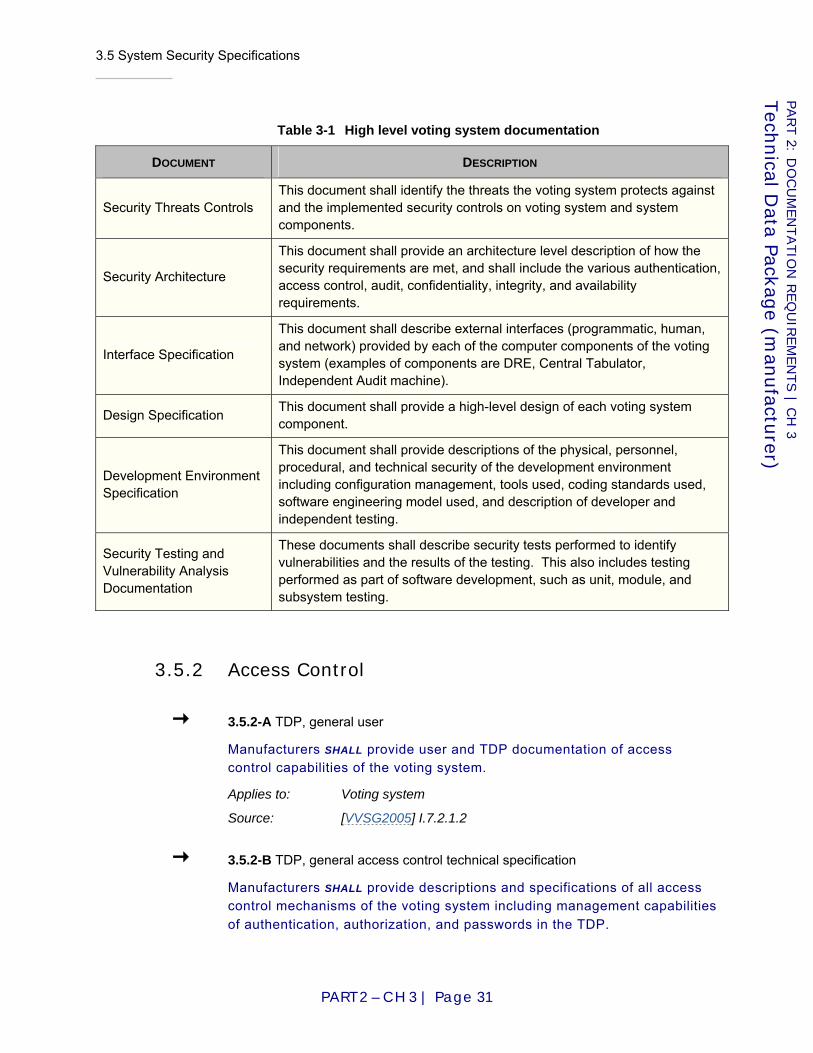
3.5 System Security Specifications
PART 2 – CH 3 | Page 31
PART 2: D
OCU
MEN
TATIO
N R
EQ
UIR
EM
EN
TS | C
H 3
Tech
nical D
ata Package (m
anufactu
rer)
Table 3-1 High level voting system documentation
DOCUMENT DESCRIPTION
Security Threats Controls This document shall identify the threats the voting system protects against and the implemented security controls on voting system and system components.
Security Architecture
This document shall provide an architecture level description of how the security requirements are met, and shall include the various authentication, access control, audit, confidentiality, integrity, and availability requirements.
Interface Specification
This document shall describe external interfaces (programmatic, human, and network) provided by each of the computer components of the voting system (examples of components are DRE, Central Tabulator, Independent Audit machine).
Design Specification This document shall provide a high-level design of each voting system component.
Development Environment Specification
This document shall provide descriptions of the physical, personnel, procedural, and technical security of the development environment including configuration management, tools used, coding standards used, software engineering model used, and description of developer and independent testing.
Security Testing and Vulnerability Analysis Documentation
These documents shall describe security tests performed to identify vulnerabilities and the results of the testing. This also includes testing performed as part of software development, such as unit, module, and subsystem testing.
3.5.2 Access Control
3.5.2-A TDP, general user
Manufacturers SHALL provide user and TDP documentation of access control capabilities of the voting system.
Applies to: Voting system
Source: [VVSG2005] I.7.2.1.2
3.5.2-B TDP, general access control technical specification
Manufacturers SHALL provide descriptions and specifications of all access control mechanisms of the voting system including management capabilities of authentication, authorization, and passwords in the TDP.

3.5 System Security Specifications
PART 2 – CH 3 | Page 32
PART 2: D
OCU
MEN
TATIO
N R
EQ
UIR
EM
EN
TS | C
H 3
Tech
nical D
ata Package (m
anufactu
rer)
Applies to: Voting system
D I S C U S S I O N
Access control mechanisms include those that are designed to permit authorized access to the voting system and prevent unauthorized access to the voting system. Specific examples of access control measures include but are not limited to: use of data and user authorization, security kernels, computer-generated password keys, and special protocols.
Source: [VVSG2005] I.7.2.1.2
3.5.2-C TDP, unauthorized access technical specification
Manufacturers SHALL provide descriptions and specifications of methods to prevent unauthorized access to the access control mechanisms of the voting system in the TDP.
Applies to: Voting system
Source: [VVSG2005] I.7.2.1.2
3.5.2-D TDP, access control dependant voting system mechanisms
Manufacturers SHALL provide descriptions and specifications of all other voting system mechanisms that are dependent upon, support, and interface with access controls in the TDP.
Applies to: Voting system
Source: [VVSG2005] I.7.2.1.2
3.5.2-E TDP, voting operations and roles
Manufacturers SHALL provide a list of all of the operations possible on the voting device and list the default roles that have permission to perform each such operation as part of the TDP.
Applies to: Voting system
Source: [VVSG2005] I.7.2.1.2
3.5.3 System Event Logging
3.5.3-A TDP, general user
Manufacturers SHALL provide TDP documentation of event logging capabilities of the voting devices.
Applies to: Voting system
Source: [VVSG2005] I.5.4

3.5 System Security Specifications
PART 2 – CH 3 | Page 33
PART 2: D
OCU
MEN
TATIO
N R
EQ
UIR
EM
EN
TS | C
H 3
Tech
nical D
ata Package (m
anufactu
rer)
3.5.3-A.1 TDP, event logging design and implementation
Manufacturers SHALL provide a technical data package that describes system event logging design and implementation.
Applies to: Voting system
Source: [VVSG2005] I.5.4
3.5.4 Software Installation
3.5.4-A TDP, software list technical data package
The manufacturer SHALL provide a list of all software related to the voting system in the technical data package (TDP).
Applies to: Voting system
D I S C U S S I O N
This requirement establishes a list of the software used by the voting system. All software related to a voting system includes application logic, border logic, third party logic, COTS software, and installation software. Installation software is used to install and configure the software on non-volatile storage of programmed devices of the voting system. Software may be in the form of source code, executable code, or both.
3.5.4-B TDP, software information
The manufacturer SHALL provide at a minimum in the TDP the following information for each piece of software related to the voting system: software product name, software version number, software manufacturer name, software manufacturer contact information, type of software (application logic, border logic, third party logic, COTS software, or installation software), list of software documentation, component identifier(s) (such as filename(s)) of the software, type of software component (executable code, source code, or data).
Applies to: Voting system
3.5.4-B.1 TDP, software location information
As part of the TDP, the manufacturer SHALL provide the location (such as full path name or memory address) and storage device (such as type and part number of storage device) where each piece of software is installed on programmed devices of the voting system.
Applies to: Programmed device

3.5 System Security Specifications
PART 2 – CH 3 | Page 34
PART 2: D
OCU
MEN
TATIO
N R
EQ
UIR
EM
EN
TS | C
H 3
Tech
nical D
ata Package (m
anufactu
rer)
D I S C U S S I O N
This requirement applies to software installed on programmed devices of the voting system. The full directory path is the final destination of the software when installed in non-volatile storage with a file system.
3.5.4-B.2 TDP, software functionality for programmed devices
As part of the TDP, the manufacturer SHALL document the functionality provided to the voting system by the software installed on programmed devices.
Applies to: Programmed device
D I S C U S S I O N
This requirement provides implementation information for test labs to support the testing of the voting system.
3.5.4-B.3 TDP, software dependencies and interaction
As part of the TDP, the manufacturer SHALL map the dependencies and interactions between software installed on programmed devices of the voting system.
Applies to: Programmed device
D I S C U S S I O N
This requirement provides implementation information for test labs to support the testing of the voting system.
3.5.4-C TDP, build environment software and hardware
As part of the TDP, the manufacturer SHALL provide a list of all software and hardware required to assemble the build environment used to create voting system software executable code including application logic, border logic, and third party logic.
Applies to: Voting system
D I S C U S S I O N
Third party software (such as operating systems, compilers, and libraries) required to build voting system software are captured by this requirement.
3.5.4-D TDP, build environment assembly procedures
As part of the TDP, the manufacturer SHALL document the procedures to assemble the build environment(s) used to create voting system software executable code including application logic, border logic, and third party logic.
Applies to: Voting system
Source: [EAC06] Section 5.6.1.2
3.5 System Security Specifications
PART 2 – CH 3 | Page 35
PART 2: D
OCU
MEN
TATIO
N R
EQ
UIR
EM
EN
TS | C
H 3
Tech
nical D
ata Package (m
anufactu
rer)
3.5.4-E TDP, voting system software build procedures
As part of the TDP, the manufacturer SHALL document the procedures used to build the voting system software executable code including application logic, border logic, and third party logic.
Applies to: Voting system
3.5.4-F TDP, original certified voting system software identification
As part of the TDP, the manufacturer SHALL provide the certification number associated with the voting system software to be updated.
Applies to: Voting system
3.5.4-G TDP, updated voting system software build procedure
As part of the TDP, the manufacturer SHALL document the procedures used to build the updated voting system software including application logic, border logic, and third party logic using the post build environment associated with the previously built voting system software.
Applies to: Voting system
3.5.4-H TDP, build environment software and hardware
As part of the TDP, the manufacturer SHALL provide a list of all software and hardware required to assemble the build environment used to create voting system software executable code including application logic, border logic, and third party logic.
Applies to: Voting system
D I S C U S S I O N
Third party software (such as operating systems, compilers, and libraries) required to build voting system software are captured by this requirement.
3.5.4-I TDP, build environment assembly procedures
As part of the TDP, the manufacturer SHALL document the procedures to assemble the build environment(s) used to create voting system software executable code including application logic, border logic, and third party logic.
Applies to: Voting system
Source: [EAC06] Section 5.6.1.2
3.5.4-J TDP, voting system software build procedures
As part of the TDP, the manufacturer SHALL document the procedures used to build the voting system software executable code including application logic, border logic, and third party logic.
3.5 System Security Specifications
PART 2 – CH 3 | Page 36
PART 2: D
OCU
MEN
TATIO
N R
EQ
UIR
EM
EN
TS | C
H 3
Tech
nical D
ata Package (m
anufactu
rer)
Applies to: Voting system
3.5.4-K TDP, original certified voting system software identification
As part of the TDP, the manufacturer SHALL provide the certification number associated with the voting system software to be updated.
Applies to: Voting system
3.5.4-L TDP, updated voting system software build procedure
As part of the TDP, the manufacturer SHALL document the procedures used to build the updated voting system software including application logic, border logic, and third party logic using the post build environment associated with the previously built voting system software.
Applies to: Voting system
3.5.5 Physical Security
3.5.5-A TDP, unauthorized physical access
The manufacturer SHALL provide a list of all voting device components to which access must be restricted and a description of the function of each said component.
Applies to: Voting device
D I S C U S S I O N
This list may be included in the technical data package a well as in the user documentation.
3.5.5-B TDP, physical port and access point
As part of the TDP, the manufacturer SHALL provide a listing of all ports and access points.
Applies to: Voting device
3.5.5-C TDP, physical lock documentation of use
For each lock used on a voting device, manufacturer SHALL document whether the lock was installed to secure an access point.
Applies to: Voting device
D I S C U S S I O N
Locks on voting devices may be used to secure access points such as doors and panels or they may be used simply to fasten a segment of the voting device’s encasement. In the former case, testing labs must verify that the lock does indeed provide a measure of security. In the latter case, the testing lab must verify that
3.5 System Security Specifications
PART 2 – CH 3 | Page 37
PART 2: D
OCU
MEN
TATIO
N R
EQ
UIR
EM
EN
TS | C
H 3
Tech
nical D
ata Package (m
anufactu
rer)
bypassing the lock does not put the security of the system in jeopardy. Manufacturer attestation should be included in User documentation, and in the TDP.
3.5.5-D TDP, power usage
Manufacturer SHALL provide a list of all physical security countermeasures that require power supplies.
Applies to: Voting device
3.5.5-E TDP, physical security
Manufacturer SHALL provide a technical data package that documents the design and implementation of all physical security controls for the voting device and its components.
Applies to: Voting device
3.5.6 System Integrity Management
3.5.6-A TDP, binaries per voting system mode
As part of the TDP, manufacturers SHALL provide a list of the binaries that are required to be executed on the electronic device for each voting system mode.
Applies to: Electronic device
D I S C U S S I O N
This requirement supports requirements in Part 1:5.5 “System Integrity Management”.
Source: [VVSG2005] I.7.4.6
3.5.7 Setup Inspection
3.5.7-A TDP, installed software identification
The manufacturer SHALL provide the technical specifications of how programmed devices of voting systems identifies installed software in the TDP.
Applies to: Programmed device
D I S C U S S I O N
The requirement provides implementation information for test labs to support the testing of the voting system.
Source: [VVSG2005] I.7.4.6 (c)

3.5 System Security Specifications
PART 2 – CH 3 | Page 38
PART 2: D
OCU
MEN
TATIO
N R
EQ
UIR
EM
EN
TS | C
H 3
Tech
nical D
ata Package (m
anufactu
rer)
3.5.7-B TDP, software integrity verification
The manufacturer SHALL provide a technical specification of how the integrity of software installed on programmed devices of the voting system is verified as part of the TDP.
Applies to: Programmed device
D I S C U S S I O N
The requirement provides implementation information for test labs to support the testing of the voting system.
Source: [VVSG2005] I.7.4.6 (c)
3.5.7-B.1 TDP, software integrity verification technique software non-modification
Software integrity verification techniques SHALL prevent the modification of software installed on programmed devices of the voting system.
Applies to: Programmed device
Source: [VVSG2005] I.7.4.6 (b) (iii)
3.5.7-C TDP, register and variable value inspection
The manufacturer SHALL provide a technical specification of how the inspection of all the voting device registers and variables is implemented by the voting device in the TDP.
Applies to: Voting device
D I S C U S S I O N
This requirement provides implementation information for test labs to support the testing of the voting system.
Source: [VVSG2005] I.7.4.6 (f)(i)
3.5.7-D TDP, backup power inspection
The manufacturers SHALL provide a technical specification of how the inspection of the remaining charge of the backup power sources is implemented by the voting device in the TDP.
Applies to: Voting device
D I S C U S S I O N
This requirement provides implementation information for test labs to support the testing of the voting system.
3.5.7-E TDP, cabling connectivity inspection
The manufacturers SHALL provide a technical specification of how the inspection of the connectivity of cabling attached to a voting device is implemented by the voting device in the TDP.
3.5 System Security Specifications
PART 2 – CH 3 | Page 39
PART 2: D
OCU
MEN
TATIO
N R
EQ
UIR
EM
EN
TS | C
H 3
Tech
nical D
ata Package (m
anufactu
rer)
Applies to: Voting device
D I S C U S S I O N
This requirement provides implementation information for test labs to support the testing of the voting system.
3.5.7-F TDP, communication operational status inspection
The manufacturers SHALL provide a technical specification of how the inspection of the operational status of the communications capability is implemented by the voting device in the TDP.
Applies to: Voting device
D I S C U S S I O N
This requirement provides implementation information for test labs to support the testing of the voting system.
3.5.7-G TDP, communication on/off inspection
The manufacturer SHALL provide a technical specification of how the inspection of the on/off status of the communications capability is implemented by the voting device in the TDP.
Applies to: Voting device
D I S C U S S I O N
This requirement provides implementation information for test labs to support the testing of the voting system.
3.5.7-H TDP, consumable inspection
The manufacturer SHALL provide a technical specification of how the inspection of the remaining amount of each consumable is implemented by the voting device in the TDP.
Applies to: Voting device
3.5.7-I TDP, calibration of voting device components inspection
The manufacturer SHALL provide a technical specification of how the inspection of the calibration for each component is implemented by the voting device in the TDP.
Applies to: Voting device
3.5.7-J TDP, calibration of voting device components adjustment
The manufacturers SHALL provide a technical specification of how the adjustment to the calibration of each component is implemented by the voting device in the TDP.
3.6 System Test Specification
PART 2 – CH 3 | Page 40
PART 2: D
OCU
MEN
TATIO
N R
EQ
UIR
EM
EN
TS | C
H 3
Tech
nical D
ata Package (m
anufactu
rer)
Applies to: Voting device
3.5.8 Cryptography
3.5.8-A TDP, cryptography
The manufacturer documentation SHALL include a precise definition of the fields in the Device Certificate, Election Certificate, the naming supported in certificates, the algorithms supported, and the format of the Election Closeout Record in the TDP.
Applies to: Voting system
3.6 System Test Specification
3.6-A TDP, development and system tests
The manufacturer SHALL provide test specifications for: a. Development test specifications; and b. System test specifications.
Applies to: Voting system
Source: [VSS2002] II.2.7
3.6.1 Development test specifications
3.6.1-A TDP, development test specifications
The manufacturer SHALL describe the plans, procedures, and data used during development and system integration to verify system logic correctness, data quality, and security. This description SHALL include:
a. Test identification and design, including test structure, test sequence or progression, and test conditions;
b. Standard test procedures, including any assumptions or constraints; c. Special purpose test procedures including any assumptions or
constraints; d. Test data, including the data source, whether it is real or simulated,
and how test data are controlled; e. Expected test results; and f. Criteria for evaluating test results.
Applies to: Voting system
D I S C U S S I O N
Documentation that is already required under the life cycle process adopted by the manufacturer may satisfy this requirement.
3.7 System Change Notes
PART 2 – CH 3 | Page 41
PART 2: D
OCU
MEN
TATIO
N R
EQ
UIR
EM
EN
TS | C
H 3
Tech
nical D
ata Package (m
anufactu
rer)
Previous iterations of these VVSG cited MIL-STD-498, Software Test Plan and Software Test Description. That standard was cancelled in 1998. Currently applicable standards include [IEEE97] and [IEEE98].
Source: [VSS2002] II.2.7.1
3.6.2 System test specifications
Note: Part 1:Chapter 3: “VVSG Background” contains several requirements for usability testing by the manufacturer and that each of these requirements also mandates that the manufacturer report the test results as part of the TDP. These requirements are not present in this section but need to be considered as part of the system test specifications.
3.6.2-A TDP, functional test specifications
The manufacturer SHALL provide specifications for verification and validation of overall system performance. These specifications SHALL cover:
a. Control and data input/output; b. Processing accuracy; c. Data quality assessment and maintenance; d. Ballot interpretation logic; e. Exception handling; f. Security; g. Production of audit trails and statistical data; h. Expected test results; and i. Criteria for evaluating test results.
Applies to: Voting system
Source: [VSS2002] II.2.7.2
3.6.2-B TDP, demonstrate fitness for purpose
The specifications SHALL identify procedures for assessing and demonstrating the suitability of the system for election use.
Applies to: Voting system
Source: [VSS2002] II.2.7.2
3.7 System Change Notes
3.7-A TDP, system change notes
Manufacturers submitting modifications for a system that has been tested previously SHALL submit system change notes.
Applies to: Voting system

3.8 Configuration for Testing
PART 2 – CH 3 | Page 42
PART 2: D
OCU
MEN
TATIO
N R
EQ
UIR
EM
EN
TS | C
H 3
Tech
nical D
ata Package (m
anufactu
rer)
D I S C U S S I O N
These will be used by the accredited test lab to assist in developing and executing the test plan for the modified system.
Source: [VSS2002] II.2.13
3.7-B TDP, system change notes content
The system change notes SHALL include the following information: a. Summary description of the nature and scope of the changes, and
reasons for each change; b. Listing of the specific changes made, citing the specific system
configuration items changed, and providing detailed references to the documentation sections changed;
c. Specific sections of the documentation that are changed (or completely revised documents, if more suitable to address a large number of changes); and
d. Documentation of the test plan and procedures executed by the manufacturer for testing the individual changes and the system as a whole, and records of test results.
Applies to: Voting system
Source: [VSS2002] II.2.13
3.8 Configuration for Testing
Configuration of hardware and software, both operating systems and applications, is critical to proper system functioning. Correct test design and sufficient test execution must account for the intended and proper configuration of all system components. If the voting system can be set up in both conforming and nonconforming configurations, the configuration actions necessary to obtain conforming behavior must be specified.
3.8-A TDP, photographs illustrating hardware set-up
The manufacturer SHALL provide photographs illustrating the proper set-up of the voting system hardware.
Applies to: Voting system
Source: New requirement
3.8-B TDP, provide answers to installation prompts
The manufacturer SHALL provide a record of all user selections that must be made during software/firmware installation for the voting system to meet the requirements of the VVSG.
Applies to: Voting system
D I S C U S S I O N
Screen shots showing the installation actions may be helpful.
3.8 Configuration for Testing
PART 2 – CH 3 | Page 43
PART 2: D
OCU
MEN
TATIO
N R
EQ
UIR
EM
EN
TS | C
H 3
Tech
nical D
ata Package (m
anufactu
rer)
Source: [VSS2002] I.4.1.1
3.8-C TDP, post-install configuration
The manufacturer SHALL also submit a record of all configuration changes that must be made to the software/firmware following its installation for the voting system to meet the requirements of the VVSG.
Applies to: Voting system
D I S C U S S I O N
Screen shots showing the configuration actions may be helpful.
Source: [VSS2002] I.4.1.1
3.8-D TDP, configuration data
The manufacturer SHALL submit all configuration data needed to set up and operate the voting system.
Applies to: Voting system
Source: New requirement

3.8 Configuration for Testing
PART 2 – CH 3 | Page 44
PART 2: D
OCU
MEN
TATIO
N R
EQ
UIR
EM
EN
TS | C
H 3
Tech
nical D
ata Package (m
anufactu
rer)

4.1 System Overview
PART 2 – CH 4 | Page 45
PART 2: D
OCU
MEN
TATIO
N R
EQ
UIR
EM
EN
TS | C
H 4
Votin
g E
quip
men
t User D
ocu
men
tation (m
anufactu
rer)
Chapter 4: Voting Equipment User Documentation (manufacturer)
This section contains requirements on the content of the documentation that manufacturers supply to jurisdictions that use their systems. In this context, "user" refers to election officials. The user documentation is also included in the TDP given to test labs.
It is not the intent of these requirements to prescribe an outline for user documentation. Manufacturers are encouraged to innovate in the quality and clarity of their user documentation. The intent of these requirements is to ensure that certain information that is of interest to end users and test labs alike will be included somewhere in the user documentation. To speed the test lab review, manufacturers should provide test labs with a short index that points out which sections of the user documentation are responsive to which sections of these requirements.
4.1 System Overview
4.1-A User documentation, system overview
In the system overview, the manufacturer SHALL provide information that enables the user to identify the functional and physical components of the system, how the components are structured, and the interfaces between them.
Applies to: Voting system
Source: [VSS2002] II.2.2
4.1-A.1 User documentation, system overview functional diagram
The system overview SHALL include a high-level functional diagram of the voting system that includes all of its components. The diagram SHALL portray how the various components relate and interact.
Applies to: Voting system
Source: [EAC06] 4.3.2.3
4.1 System Overview
PART 2 – CH 4 | Page 46
PART 2: D
OCU
MEN
TATIO
N R
EQ
UIR
EM
EN
TS | C
H 4
Votin
g E
quip
men
t User D
ocu
men
tation (m
anufactu
rer)
4.1.1 System description
4.1.1-A User documentation, system description
The system description SHALL include written descriptions, drawings and diagrams that present:
a. A description of the functional components (or subsystems) as defined by the manufacturer (e.g., environment, election management and control, vote recording, vote conversion, reporting, and their logical relationships);
b. A description of the operational environment of the system that provides an overview of the hardware, firmware, software, and communications structure;
c. A concept of operations that explains each system function and how the function is achieved in the design;
d. Descriptions of the functional and physical interfaces between subsystems and components;
e. Identification of all COTS products (both hardware and software) included in the system and/or used as part of the system's operation, identifying the name, manufacturer, and version used for each such component;
f. Communications (dial-up, network) software; g. Interfaces among internal components and interfaces with external
systems. For components that interface with other components for which multiple products may be used, the manufacturer SHALL identify file specifications, data objects, or other means used for information exchange, and the public standard used for such file specifications, data objects, or other means; and
h. Benchmark directory listings for all software and firmware and associated documentation included in the manufacturer's release in the order in which each piece of software or firmware would normally be installed upon system setup and installation.
Applies to: Voting system
Source: [VSS2002] II.2.2.1
4.1.1-B User documentation, identify software and firmware by origin
The system description SHALL include the identification of all software and firmware items, indicating items that were:
a. Written in-house; b. Written by a subcontractor; c. Procured as COTS; and d. Procured and modified, including descriptions of the modifications to
the software or firmware and to the default configuration options. Applies to: Voting system
Source: [VSS2002] II.2.5.3.c

4.1 System Overview
PART 2 – CH 4 | Page 47
PART 2: D
OCU
MEN
TATIO
N R
EQ
UIR
EM
EN
TS | C
H 4
Votin
g E
quip
men
t User D
ocu
men
tation (m
anufactu
rer)
4.1.1-C User documentation, traceability of procured software
The system description SHALL include a declaration that procured software items were obtained directly from the manufacturer or a licensed dealer or distributor.
Applies to: Voting system
D I S C U S S I O N
For most noncommercial software, this would mean a declaration that the software was downloaded from the canonical site or a trustworthy mirror. It is generally accepted practice for the core contributors to major open-source software packages to digitally sign the distributions. Verifying these signatures provides greater assurance that the package has not been modified.
Source: [VSS2002] II.2.5.3
4.1.2 System performance
4.1.2-A User documentation, system performance
The manufacturer SHALL provide system performance information including: a. Device capacities and limits that were stated in the implementation
statement (see Part 1:2.4 “Software Independence”); b. If not already covered in the implementation statement, performance
characteristics of each operating mode and function in terms of expected and maximum speed, throughput capacity, maximum volume (maximum number of voting positions and maximum number of ballot styles supported), and processing frequency;
c. Quality attributes such as reliability, maintainability, availability, usability, and portability;
d. Provisions for safety, security, privacy, and continuity of operation; and
e. Design constraints, applicable standards, and compatibility requirements.
Applies to: Voting system
Source: [VSS2002] II.2.2.2
4.1.2-A.1 User documentation, central tabulator maximum tabulation rate
The maximum tabulation rate for a central tabulator SHALL be documented by the manufacturer. This documentation SHALL include the maximum tabulation rate for individual components that impact the overall maximum tabulation rate.
Applies to: Central tabulator
D I S C U S S I O N
The capacity to convert the marks on individual ballots into signals is uniquely important to central count systems.
Source: [VSS2002] I.3.2.5.1.1
4.2 System Functionality Description
PART 2 – CH 4 | Page 48
PART 2: D
OCU
MEN
TATIO
N R
EQ
UIR
EM
EN
TS | C
H 4
Votin
g E
quip
men
t User D
ocu
men
tation (m
anufactu
rer)
4.1.2-A.2 User documentation, reliably detectable marks
For an optical scanner, the manufacturer SHALL document what constitutes a reliably detectable mark versus a marginal mark.
Applies to: Optical scanner
D I S C U S S I O N
See Part 1:7.7.5.1 “Marginal marks”. The specification may be parameterized by configuration values and should state the uncertainty.
Source: New requirement
4.2 System Functionality Description
4.2-A User documentation, system functionality description
The manufacturer SHALL provide a listing of the system's functional processing capabilities, encompassing capabilities required by the VVSG, and any additional capabilities provided by the system, with a description of each capability.
a. The manufacturer SHALL explain, in a manner that is understandable to users, the capabilities of the system that were declared in the implementation statement;
b. Additional capabilities (extensions) SHALL be clearly indicated; c. Required capabilities that may be bypassed or deactivated during
installation or operation by the user SHALL be clearly indicated; d. Additional capabilities that function only when activated during
installation or operation by the user SHALL be clearly indicated; and e. Additional capabilities that normally are active but may be bypassed
or deactivated during installation or operation by the user SHALL be clearly indicated.
Applies to: Voting system
Source: [VSS2002] II.2.3
4.3 System Security Specification
4.3.1 Access control
4.3.1-A User documentation, access control implementation, configuration, and
management
Manufacturers SHALL provide user documentation containing guidelines and usage instructions on implementing, configuring, and managing access control capabilities.
Applies to: Voting system
4.3 System Security Specification
PART 2 – CH 4 | Page 49
PART 2: D
OCU
MEN
TATIO
N R
EQ
UIR
EM
EN
TS | C
H 4
Votin
g E
quip
men
t User D
ocu
men
tation (m
anufactu
rer)
Source: [VVSG2005] I.7.2.1.2
4.3.1-B User documentation, access control policy template
Manufacturers SHALL provide, within the user documentation, an access control policy template or instructions to facilitate the implementation of the access control policy and associated access controls on the voting system.
Applies to: Voting system
D I S C U S S I O N
Access control policy requirements include the minimum baseline policy definitions necessary for testing and implementation of the voting system. The policies may be pre-defined within the voting system or provided as guidelines in the documentation.
Source: [VVSG2005] I.7.2.1
4.3.1-C User documentation, model access control policy
Manufacturers SHALL provide, within the user documentation, a model access control policy under which the voting system was designed to operate and a description of the hazards of deviating from this policy.
Applies to: Voting system
D I S C U S S I O N
The model access control policy includes the assumptions that were made when the system was designed, the justification for the policy, and the hazards of deviating from the policy.
Source: [VVSG2005] I.7.2.1
4.3.1-D User documentation, privileged account
The manufacturer SHALL disclose and document information on all privileged accounts included on the voting system.
Applies to: Voting system
D I S C U S S I O N
Information on privileged accounts include the name of the account, purpose, capabilities and permissions, and how to disable the account in the user documentation.
Source: [VVSG2005] I.7.2.1.2

4.3 System Security Specification
PART 2 – CH 4 | Page 50
PART 2: D
OCU
MEN
TATIO
N R
EQ
UIR
EM
EN
TS | C
H 4
Votin
g E
quip
men
t User D
ocu
men
tation (m
anufactu
rer)
4.3.2 System event logging
4.3.2-A User documentation, system event logging
Manufacturers SHALL provide user documentation that describes system event logging capabilities and usage.
Applies to: Voting system
Source: [VVSG2005] I.5.4
4.3.2-B User documentation, log format
Manufacturers SHALL publicly publish fully documented log format information.
Applies to: Voting system
D I S C U S S I O N
The log format and the meaning of all possible types of log entries must be fully documented in sufficient detail to allow independent manufacturers to implement utilities to parse the log file. This documentation must be publicly available, free of charge, and not just in the TDP. The documentation may be housed by the EAC or the test lab.
Source: [VVSG2005] I.5.4
4.3.3 Software installation
4.3.3-A User documentation, software list
The manufacturer SHALL provide a list of all software to be installed on the programmed devices of the voting system and installation software used to install the software in the user documentation.
Applies to: Programmed device
D I S C U S S I O N
Software to be installed on programmed devices of the voting system includes executable code, configuration files, data files, and election specific software.
4.3.3-B User documentation, software information
The manufacturer SHALL provide at a minimum in the user documentation the following information for each piece of software to be installed or used to install software on programmed devices of the voting system: software product name, software version number, software manufacturer name, software manufacturer contact information, type of software (application logic, border logic, third party logic, COTS software, or installation software), list of software documentation, component identifier(s) (such filename(s)) of

4.3 System Security Specification
PART 2 – CH 4 | Page 51
PART 2: D
OCU
MEN
TATIO
N R
EQ
UIR
EM
EN
TS | C
H 4
Votin
g E
quip
men
t User D
ocu
men
tation (m
anufactu
rer)
the software, type of software component (executable code, source code, or data).
Applies to: Programmed device
4.3.3-C User documentation, software location information
The manufacturer SHALL provide in the user documentation the location (such as full path name or memory address) and storage device (such as type and part number of storage device) where each piece of software is installed on programmed devices of the voting system.
Applies to: Programmed device
D I S C U S S I O N
This requirement applies to software installed on programmed devices of the voting system. The full directory path is the final destination of the software when installed on non-volatile storage with a file system.
4.3.3-D User documentation, election specific software identification
The manufacturer SHALL identify election specific software in the user documentation.
Applies to: Programmed device
4.3.3-E User documentation, installation software and hardware
The manufacturer SHALL provide a list of software and hardware required to install software on programmed devices of the voting system in the user documentation.
Applies to: Programmed device
4.3.3-F User documentation, software installation procedure
The manufacturer SHALL document the software installation procedures used to install software on programmed devices of the voting system in user documentation.
Applies to: Programmed device
Source: [VVSG2005] Volume III, Section 2.2.3(a)
4.3.3-G User documentation, compiler installation prohibited
The software installation procedures used to install software on programmed devices of the voting system SHALL result in no compilers being installed on the programmed device.
Applies to: Programmed device

4.3 System Security Specification
PART 2 – CH 4 | Page 52
PART 2: D
OCU
MEN
TATIO
N R
EQ
UIR
EM
EN
TS | C
H 4
Votin
g E
quip
men
t User D
ocu
men
tation (m
anufactu
rer)
4.3.3-G.1 User documentation, programmed device configuration baseline binary
image creation
To replicate programmed device configurations, the software installation procedures SHALL create a baseline binary image of the initial programmed device configuration on an unalterable storage media with a digital signature.
Applies to: Programmed device
D I S C U S S I O N
Unalterable storage media includes technology such as a CD-R, but not CD-RW.
4.3.3-G.2 User documentation, programmed device configuration replication
The software installation procedures SHALL use the baseline binary image of the initial programmed device configuration on an unalterable storage media to replicate the configuration on to other programmed devices.
Applies to: Programmed device
D I S C U S S I O N
Unalterable storage media includes technology such as a CD-R, but not CD-RW.
4.3.3-H User documentation, software installation record creation
The software installation procedures SHALL specify the creation of a software installation record that includes at a minimum: a unique identifier (such as a serial number) for the record; a list of unique identifiers of unalterable storage media associated with the record; the time, date, and location of the software installation; names, affiliations, and signatures of all people present; copies of the procedures used to install the software on the programmed devices of the voting system; the certification number of the voting system; list of the software installed on programmed devices of the voting system; and a unique identifier (such as a serial number) of the vote-capture device or EMS which the software is installed.
Applies to: Programmed device
4.3.3-I User documentation, procurement of voting system software
The software installation procedures SHALL specify that voting system software be obtained from test labs or distribution repositories.
Applies to: Programmed device
D I S C U S S I O N
Distribution repositories provide software they receive to parties approved by the owner of the software.
4.3 System Security Specification
PART 2 – CH 4 | Page 53
PART 2: D
OCU
MEN
TATIO
N R
EQ
UIR
EM
EN
TS | C
H 4
Votin
g E
quip
men
t User D
ocu
men
tation (m
anufactu
rer)
4.3.3-J User documentation, open market procurement of COTS software
The software installation procedures SHALL specify that COTS software be obtained from the open market.
Applies to: Programmed device
4.3.3-K User documentation, erasable storage media preparation
The software installation procedures SHALL specify how previously stored information on erasable storage media is removed before installing software on the media.
Applies to: Programmed device
D I S C U S S I O N
The purpose of this requirement is to prepare erasable storage media for use by the programmed devices of the voting system. The requirement does not require the prevention of previously stored information leakage or recovery. Simply deleting files from file systems, flashing memory cards, and removing electrical power from volatile memory satisfies this requirement.
4.3.3-L User documentation, installation media unalterable storage media
The software installation procedures SHALL specify that unalterable storage media be used to install software on programmed devices of the voting system.
Applies to: Programmed device
D I S C U S S I O N
Unalterable storage media includes technology such as a CD-R, but not CD-RW.
4.3.4 Physical security
4.3.4-A User documentation, physical security
Manufacturer SHALL provide user documentation explaining the implementation of all physical security controls for the voting device, including model procedures necessary for effective use of countermeasures.
Applies to: Voting device

4.3 System Security Specification
PART 2 – CH 4 | Page 54
PART 2: D
OCU
MEN
TATIO
N R
EQ
UIR
EM
EN
TS | C
H 4
Votin
g E
quip
men
t User D
ocu
men
tation (m
anufactu
rer)
4.3.5 Setup inspection
4.3.5-A User documentation, model setup inspection process
The manufacturer SHALL provide a model setup inspection process that the voting device was designed to support and description of the risks of deviating from the process in the user documentation.
Applies to: Voting device
D I S C U S S I O N
The model setup inspection process provides a means to inspect various properties of voting devices as needed during the election process.
4.3.5-A.1 User documentation, minimum properties included in a model setup
inspection process
A model setup inspection process SHALL at a minimum include the inspection of voting system software, storage locations that hold election information that changes during an election, other voting device properties, and execution of logic and accuracy testing related to readiness of use in an election.
Applies to: Voting device
D I S C U S S I O N
See requirements in Part 1:5.2 “Setup Inspection”.
Source: [VVSG2005] I.7.4.6 (a) and (f)
4.3.5-B User documentation, model setup inspection record generation
The model setup inspection process SHALL describe the records that result from performing the setup inspection process.
Applies to: Voting device
Source: [VVSG2005] I.5.4.2
4.3.5-C User documentation, installed software identification procedure
The manufacturer SHALL provide the procedures to identify all software installed on programmed devices of the voting system in the user documentation.
Applies to: Programmed device
D I S C U S S I O N
This requirement provides the ability to identify if the proper software is installed and that no other software is present on programmed devices of the voting system. This requirement covers software stored on storage media with or without a file system.
4.3 System Security Specification
PART 2 – CH 4 | Page 55
PART 2: D
OCU
MEN
TATIO
N R
EQ
UIR
EM
EN
TS | C
H 4
Votin
g E
quip
men
t User D
ocu
men
tation (m
anufactu
rer)
Source: [VVSG2005] I.7.4.6 (b)(ii)
4.3.5-D User documentation, software integrity verification procedure
The manufacturer SHALL describe the procedures to verify the integrity of software installed on programmed devices of voting system in the user documentation.
Applies to: Programmed device
Source: [VVSG2005] I.7.4.6 (b)(ii)
4.3.5-E User documentation, election information value
The manufacturer SHALL provide the values of voting device storage locations that hold election information that changes during the election, except for the values set to conduct a specific election in the user documentation.
Applies to: Voting device
Source: [VVSG2005] I.7.4.6 (f)(ii)
4.3.5-F User documentation, maximum and minimum values of election information
storage locations
The manufacturer SHALL provide the maximum and minimum values voting device storage locations that hold election information changes during an election can store in the user documentation.
Applies to: Voting device
Source: [VVSG2005] I.7.4.6 (f)(ii)
4.3.5-G User documentation, register and variable value inspection procedure
The manufacturer SHALL provide the procedures to inspect the values of voting device storage locations that hold election information that changes for an election in the user documentation.
Applies to: Voting device
Source: [VVSG2005] I.7.4.6 (f)(i)
4.3.5-H User documentation, backup power operational range
The manufacturers SHALL provide the nominal operational range for the backup power sources of the voting device in the user documentation.
Applies to: Voting device
4.3 System Security Specification
PART 2 – CH 4 | Page 56
PART 2: D
OCU
MEN
TATIO
N R
EQ
UIR
EM
EN
TS | C
H 4
Votin
g E
quip
men
t User D
ocu
men
tation (m
anufactu
rer)
4.3.5-I User documentation, backup power inspection procedure
The manufacturer SHALL provide the procedures to inspect the remaining charge of the backup power sources of the voting device in the user documentation.
Applies to: Voting device
4.3.5-J User documentation, cabling connectivity inspection procedure
The manufacturer SHALL provide the procedures to inspect the connectivity of the cabling attached to the voting device in the user documentation.
Applies to: Voting device
4.3.5-K User documentation, communications operational status inspection
procedure
The manufacturer SHALL provide the procedures to inspect the operational status of the communications capabilities of the voting device in the user documentation.
Applies to: Voting device
4.3.5-L User documentation, communications on/off status inspection procedure
The manufacturer SHALL provide the procedures to inspect the on/off status of the communications capabilities of the voting device in the user documentation.
Applies to: Voting device
4.3.5-M User documentation, consumables quantity of voting equipment
The manufacturer SHALL provide a list of consumables associated with the voting device, including estimated number of usages per quantity of consumable in the user documentation.
Applies to: Voting device
4.3.5-N User documentation, consumable inspection procedure
The manufacturer SHALL provide the procedures to inspect the remaining amount of each consumable of the voting device in the user documentation.
Applies to: Voting device

4.3 System Security Specification
PART 2 – CH 4 | Page 57
PART 2: D
OCU
MEN
TATIO
N R
EQ
UIR
EM
EN
TS | C
H 4
Votin
g E
quip
men
t User D
ocu
men
tation (m
anufactu
rer)
4.3.5-O User documentation, calibration of voting device components nominal
range
The manufacturer SHALL provide a list of components associated with the voting device that require calibration and the nominal operating ranges for each component in the user documentation.
Applies to: Voting device
4.3.5-P User documentation, calibration of voting device components inspection
procedure
The manufacturer SHALL provide the procedures to inspect the calibration of each component in the user documentation.
Applies to: Voting device
4.3.5-Q User documentation, calibration of voting device components adjustment
procedure
The manufacturer SHALL provide the procedures to adjust the calibration of each component in the user documentation.
Applies to: Voting device
4.3.5-R User documentation, model checklist of properties to be inspected
The manufacturer SHALL provide a model checklist of other properties of the voting device to be inspected, including a description of the risks on not performing a given inspection in the user documentation.
Applies to: Voting device
D I S C U S S I O N
Voting devices may have other properties that need to be inspected that are not covered in Part 1:5.2 “Setup Inspection”. This requirement provides a mechanism for the properties not covered in Part 1 Section 5.2 to be captured.
4.3.5-R.1 User documentation, minimal voting device properties covered by model
checklist
The model checklist of other properties of the voting device to be inspected SHALL at a minimum include: the inspection of backup power sources, cabling, communications capabilities, consumables, calibration of voting device components, general physical features of the voting device, and securing external interfaces of the voting device not being used.
Applies to: Voting device

4.3 System Security Specification
PART 2 – CH 4 | Page 58
PART 2: D
OCU
MEN
TATIO
N R
EQ
UIR
EM
EN
TS | C
H 4
Votin
g E
quip
men
t User D
ocu
men
tation (m
anufactu
rer)
D I S C U S S I O N
Voting device may have other properties that need to be inspected that are not covered in Part 1:5.2 “Setup Inspection”. This requirement provides a mechanism for the properties not covered in Part 1 Section 5.2 to be captured.
4.3.6 Audit
4.3.6-A User documentation, pollbook audit
The voting system’s user documentation SHALL fully specify a secure, transparent, workable and accurate process for producing all records necessary from the devices and carrying out the pollbook audit.
Applies to: Voting system
D I S C U S S I O N
In order to fully support the pollbook audit, the voting system documentation must provide enough information for election officials to carry out the auditing step. This includes explaining how to generate all needed reports, how to check the reports against one another for agreement, and how to deal with errors and other unusual problems that come up during the audit step.
4.3.6-B User documentation, hand audit
The voting system’s user documentation SHALL fully specify a secure, transparent, workable and accurate process for producing all records necessary from the devices and carrying out the hand audit.
Applies to: Voting system
D I S C U S S I O N
The user documentation must explain how to produce all necessary reports and reconcile the records by hand-auditing.
4.3.6-C User documentation, ballot count and vote total auditing
The voting system’s user documentation SHALL fully specify a secure, transparent, workable and accurate process for producing all records necessary from the devices and carrying out the final election tally.
Applies to: Voting system
D I S C U S S I O N
In order to fully support the audit, the voting system documentation must provide enough information for election officials to carry out the auditing step. This includes explaining how to generate all needed reports, how to check the reports against one another for agreement, and how to deal with errors and other unusual problems that come up during the audit step.

4.4 System Operations Manual
PART 2 – CH 4 | Page 59
PART 2: D
OCU
MEN
TATIO
N R
EQ
UIR
EM
EN
TS | C
H 4
Votin
g E
quip
men
t User D
ocu
men
tation (m
anufactu
rer)
4.3.6-D User documentation, observational testing
The voting system’s user documentation SHALL fully specify a secure, transparent, workable and accurate process for observational testing.
Applies to: Voting system
4.3.6-E User documentation, machine readability of VVPAT VVPR
The manufacturer shall provide documentation for a procedure to scan VVPAT VVPR by optical character recognition.
Applies to: VVPAT
Source: [VVSG2005] I.7.9.3-g
4.4 System Operations Manual
4.4-A User documentation, system operations manual
The system operations manual SHALL provide all information necessary for system use by all personnel who support pre-election and election preparation, polling place activities, and central counting activities, as applicable, with regard to all system functions and operations identified in Part 2:4.2 “System Functionality Description”.
Applies to: Voting system
D I S C U S S I O N
The nature of the instructions for operating personnel will depend upon the overall system design and required skill level of system operations support personnel.
Source: [VSS2002] II.2.8
4.4-B Operations manual, support training
The system operations manual SHALL contain all information that is required for the preparation of detailed system operating procedures and for the training of administrators, central election officials, election judges, and poll workers.
Applies to: Voting system
Source: [VSS2002] II.2.8
4.4 System Operations Manual
PART 2 – CH 4 | Page 60
PART 2: D
OCU
MEN
TATIO
N R
EQ
UIR
EM
EN
TS | C
H 4
Votin
g E
quip
men
t User D
ocu
men
tation (m
anufactu
rer)
4.4.1 Introduction
4.4.1-A Operations manual, functions and modes
The manufacturer SHALL provide a summary of system operating functions and modes to permit understanding of the system's capabilities and constraints.
Applies to: Voting system
Source: [VSS2002] II.2.8.1
4.4.1-B Operations manual, roles
The roles of operating personnel SHALL be identified and related to the operating modes of the system.
Applies to: Voting system
Source: [VSS2002] II.2.8.1
4.4.1-C Operations manual, conditional actions
Decision criteria and conditional operator functions (such as error and failure recovery actions) SHALL be described.
Applies to: Voting system
Source: [VSS2002] II.2.8.1
4.4.1-D Operations manual, references
The manufacturer SHALL also list all reference and supporting documents pertaining to the use of the system during election operations.
Applies to: Voting system
Source: [VSS2002] II.2.8.1
4.4.2 Operational environment
4.4.2-A Operations manual, operational environment
The manufacturer SHALL describe the system environment and the interface between the election official or voter and the system.
Applies to: Voting system
Source: [VSS2002] II.2.8.2
4.4 System Operations Manual
PART 2 – CH 4 | Page 61
PART 2: D
OCU
MEN
TATIO
N R
EQ
UIR
EM
EN
TS | C
H 4
Votin
g E
quip
men
t User D
ocu
men
tation (m
anufactu
rer)
4.4.2-B Operations manual, operational environment details 1
The manufacturer SHALL identify all facilities, furnishings, fixtures, and utilities that will be required for equipment operations, including equipment that operates at the:
a. Polling place; b. Central count facility; and c. Other locations.
Applies to: Voting system
Source: [VSS2002] II.2.8.2
4.4.2-C Operations manual, operational environment details 2
The user documentation supplied by the manufacturer SHALL include a statement of all requirements and restrictions regarding environmental protection, electrical service, recommended auxiliary power, telecommunications service, and any other facility or resource required for the proper installation and operation of the system.
Applies to: Voting system
Source: [VSS2002] I.3.2.2
4.4.3 System installation and test specification
4.4.3-A Operations manual, readiness testing
The manufacturer SHALL provide specifications for testing of system installation and readiness.
Applies to: Voting system
D I S C U S S I O N
Readiness testing refers to steps that election officials can take after deploying and configuring equipment to establish that it was correctly deployed and configured. Logic and accuracy testing would be part of this.
Source: [VSS2002] II.2.8.3
4.4.3-A.1 Operations manual, readiness test entire system
These specifications SHALL cover testing of all components of the system and all locations of installation (e.g., polling place, central count facility), and SHALL address all elements of system functionality and operations identified in Part 2:4.2 “System Functionality Description” above, including general capabilities and functions specific to particular voting activities.
Applies to: Voting system
Source: [VSS2002] II.2.8.3
4.4 System Operations Manual
PART 2 – CH 4 | Page 62
PART 2: D
OCU
MEN
TATIO
N R
EQ
UIR
EM
EN
TS | C
H 4
Votin
g E
quip
men
t User D
ocu
men
tation (m
anufactu
rer)
4.4.4 Operational features
4.4.4-A Operations manual, features
The manufacturer SHALL provide documentation of system operating features that includes:
a. Detailed descriptions of all input, output, control, and display features accessible to the operator or voter;
b. Examples of simulated interactions to facilitate understanding of the system and its capabilities;
c. Sample data formats and output reports; and d. Illustration and description of all status indicators and information
messages. Applies to: Voting system
Source: [VSS2002] II.2.8.4
4.4.4-B Operations manual, document straight party override algorithms
For systems that support straight party voting, the manufacturer SHALL document the available algorithms for counting straight party overrides.
Applies to: Straight party voting
D I S C U S S I O N
See Requirement Part 1:7.7.2-A.12.
Source: New requirement
4.4.4-C Operations manual, document double vote reconciliation algorithms
For systems that support write-in voting, the manufacturer SHALL document the available algorithms for reconciling write-in double votes.
Applies to: Write-ins
D I S C U S S I O N
See Requirement Part 1:7.7.2-A.9.
Source: New requirement
4.4.5 Operating procedures
4.4.5-A Operations manual, operating procedures
The manufacturer SHALL provide documentation of system operating procedures that:
a. Provides a detailed description of procedures required to initiate, control, and verify proper system operation;

4.4 System Operations Manual
PART 2 – CH 4 | Page 63
PART 2: D
OCU
MEN
TATIO
N R
EQ
UIR
EM
EN
TS | C
H 4
Votin
g E
quip
men
t User D
ocu
men
tation (m
anufactu
rer)
b. Provides procedures that clearly enable the operator to assess the correct flow of system functions (as evidenced by system-generated status and information messages);
c. Provides procedures that clearly enable the administrator to intervene in system operations to recover from an abnormal system state;
d. Defines and illustrates the procedures and system prompts for situations where operator intervention is required to load, initialize, and start the system;
e. Defines and illustrates procedures to enable and control the external interface to the system operating environment if supporting hardware and software are involved. Such information also SHALL be provided for the interaction of the system with other data processing systems or data interchange protocols;
f. Provides administrative procedures and off-line operator duties (if any) if they relate to the initiation or termination of system operations, to the assessment of system status, or to the development of an audit trail;
g. Supports successful ballot and program installation and control by central election officials;
h. Provides a schedule and steps for the software and ballot installation, including a table outlining the key dates, events and deliverables; and
i. Specifies diagnostic tests that may be employed to identify problems in the system, verify the correction of problems, and isolate and diagnose faults from various system states.
Applies to: Voting system
Source: [VSS2002] I.2.3.3.a and II.2.8.5
4.4.5-B Operations manual, VVPAT printer error recovery guidelines
Manufacturers of VVPATs SHALL provide documentation for procedures to recover from VVPAT printer errors and faults including procedures for how to cancel a vote suspended during an error.
Applies to: VVPAT
D I S C U S S I O N
If the printer irrecoverably locks up, the vote needs to be able to be canceled, so the voter can cast a vote on another device. Alternatively, it would be okay to store the vote as is, if the vote is complete. This requirement restates [VVSG2005] I.7.9.4-k by requiring documentation for recovering from printer errors.
Source: [VVSG2005] I.7.9.4-k
4.4.5-C Operations manual, Paper-roll VVPATs privacy-ensuring procedures
Manufacturers of paper-roll VVPATs SHALL provide documentation describing necessary procedures for handling the paper roll in a way that preserves voter privacy.
Applies to: VVPAT
4.4 System Operations Manual
PART 2 – CH 4 | Page 64
PART 2: D
OCU
MEN
TATIO
N R
EQ
UIR
EM
EN
TS | C
H 4
Votin
g E
quip
men
t User D
ocu
men
tation (m
anufactu
rer)
D I S C U S S I O N
Along with a secure, opaque container designed to accommodate tamper-seals and a lock, the voting system needs to document what must be done to protect voter privacy with the paper rolls. The goal of this requirement is to ensure that the election officials are given guidance on exactly what must be done to protect the privacy of voters.
Source: [VVSG2005] I.7.9.5-b
4.4.6 Documentation for poll workers
Documentation for poll workers is covered under Part 1:3.2.8 “Usability for poll workers” and 3.3.1 “General”.
4.4.7 Operations support
4.4.7-A Operations manual, operations support
The manufacturer SHALL provide documentation of system operating procedures that:
a. Defines the procedures required to support system acquisition, installation, and readiness testing; and
b. Describes procedures for providing technical support, system maintenance and correction of defects and for incorporating hardware upgrades and new software releases.
Applies to: Voting system
Source: [VSS2002] II.2.8.6
4.4.8 Transportation and storage
4.4.8-A Operations manual, transportation
The manufacturer SHALL include any special instructions for preparing voting devices for shipment.
Applies to: Voting system
Source: New requirement
4.4.8-B Operations manual, storage
The manufacturer SHALL include any special storage instructions for voting devices.
Applies to: Voting system
Source: [VSS2002] I.3.2.2.1

4.5 System Maintenance Manual
PART 2 – CH 4 | Page 65
PART 2: D
OCU
MEN
TATIO
N R
EQ
UIR
EM
EN
TS | C
H 4
Votin
g E
quip
men
t User D
ocu
men
tation (m
anufactu
rer)
4.4.8-C Operations manual, procedures to ensure archivalness
The manufacturer SHALL detail the care and handling precautions necessary for removable media and records to satisfy Requirement Part 1:6.5.1-A.
Applies to: Voting system
Source: New requirement
4.4.9 Appendices
The manufacturer may provide descriptive material and data supplementing the various sections of the body of the system operations manual. The content and arrangement of appendices are at the discretion of the manufacturer. Topics recommended for discussion include:
♦ Glossary: A listing and brief definition of all terms that may be unfamiliar to persons not trained in either voting systems or computer operations;
♦ References: A list of references to all manufacturer documents and to other sources related to operation of the system;
♦ Detailed Examples: Detailed scenarios that outline correct system responses to faulty operator input. Alternative procedures may be specified depending on the system state; and
♦ Manufacturer's Recommended Security Procedures: Security procedures that are to be executed by the system operator.
4.5 System Maintenance Manual
4.5-A User documentation, system maintenance manual
The system maintenance manual SHALL provide information to support election workers, information systems personnel, or maintenance personnel in the adjustment or removal and replacement of components or modules in the field.
Applies to: Voting system
D I S C U S S I O N
Technical documentation needed solely to support the repair of defective components or modules ordinarily done by the manufacturer or software developer is not required.
Source: [VSS2002] II.2.9
4.5-B Maintenance manual, general contents
The manufacturer SHALL describe service actions recommended to correct malfunctions or problems; personnel and expertise required to repair and

4.5 System Maintenance Manual
PART 2 – CH 4 | Page 66
PART 2: D
OCU
MEN
TATIO
N R
EQ
UIR
EM
EN
TS | C
H 4
Votin
g E
quip
men
t User D
ocu
men
tation (m
anufactu
rer)
maintain the system, equipment, and materials; and facilities needed for proper maintenance.
Applies to: Voting system
Source: [VSS2002] II.2.9
4.5.1 Introduction
4.5.1-A Maintenance manual, equipment overview, maintenance viewpoint
The manufacturer SHALL describe the structure and function of the hardware, firmware and software for election preparation, programming, vote recording, tabulation, and reporting in sufficient detail to provide an overview of the system for maintenance and for identification of faulty hardware or software.
Applies to: Voting system
Source: [VSS2002] II.2.9.1
4.5.1-A.1 Maintenance manual, equipment overview details
The description SHALL include a concept of operations that fully describes such items as:
a. Electrical and mechanical functions of the equipment; b. How the processes of ballot handling and reading are performed
(paper-based systems); c. For electronic vote-capture devices, how vote selection and casting
of the ballot are performed; d. How transmission of data over a network is performed (if applicable); e. How data are handled in the processor and memory units; f. How data output is initiated and controlled; g. How power is converted or conditioned; and h. How test and diagnostic information is acquired and used.
Applies to: Voting system
Source: [VSS2002] II.2.9.1
4.5.2 Maintenance procedures
4.5.2-A Maintenance manual, maintenance procedures
The manufacturer SHALL describe preventive and corrective maintenance procedures for hardware, firmware and software.
Applies to: Voting system
Source: [VSS2002] II.2.9.2

4.5 System Maintenance Manual
PART 2 – CH 4 | Page 67
PART 2: D
OCU
MEN
TATIO
N R
EQ
UIR
EM
EN
TS | C
H 4
Votin
g E
quip
men
t User D
ocu
men
tation (m
anufactu
rer)
4.5.2.1 Preventive maintenance procedures
4.5.2.1-A Maintenance manual, preventive maintenance procedures
The manufacturer SHALL identify and describe: a. All required and recommended preventive maintenance tasks,
including software and data backup, database performance analysis, and database tuning;
b. Number and skill levels of personnel required for each task; c. Parts, supplies, special maintenance equipment, software tools, or
other resources needed for maintenance; and d. Any maintenance tasks that must be coordinated with the
manufacturer or a third party (such as coordination that may be needed for COTS used in the system).
Applies to: Voting system
Source: [VSS2002] II.2.9.2.1
4.5.2.2 Corrective maintenance procedures
4.5.2.2-A Maintenance manual, troubleshooting procedures
The manufacturer SHALL provide fault detection, fault isolation, correction procedures, and logic diagrams for all operational abnormalities identified by design analysis and operating experience.
Applies to: Voting system
Source: [VSS2002] II.2.9.2.2
4.5.2.2-B Maintenance manual, troubleshooting procedures details
The manufacturer SHALL identify specific procedures to be used in diagnosing and correcting problems in the system hardware, firmware and software. Descriptions SHALL include:
a. Steps to replace failed or deficient equipment; b. Steps to correct deficiencies or faulty operations in software or
firmware; c. Modifications that are necessary to coordinate any modified or
upgraded software or firmware with other modules; d. Number and skill levels of personnel needed to accomplish each
procedure; e. Special maintenance equipment, parts, supplies, or other resources
needed to accomplish each procedure; and f. Any coordination required with the manufacturer, or other party, for
COTS. Applies to: Voting system
Source: [VSS2002] II.2.9.2.2
4.5 System Maintenance Manual
PART 2 – CH 4 | Page 68
PART 2: D
OCU
MEN
TATIO
N R
EQ
UIR
EM
EN
TS | C
H 4
Votin
g E
quip
men
t User D
ocu
men
tation (m
anufactu
rer)
4.5.3 Maintenance equipment
4.5.3-A Maintenance manual, special equipment
The manufacturer SHALL identify and describe any special purpose test or maintenance equipment recommended for fault isolation and diagnostic purposes.
Applies to: Voting system
Source: [VSS2002] II.2.9.3
4.5.4 Parts and materials
4.5.4-A Maintenance manual, parts and materials
Manufacturers SHALL provide detailed documentation of parts and materials needed to operate and maintain the system.
Applies to: Voting system
Source: [VSS2002] II.2.9.4
4.5.4.1 Common standards
4.5.4.1-A Maintenance manual, approved parts list
The manufacturer SHALL provide a complete list of approved parts and materials needed for maintenance. This list SHALL contain sufficient descriptive information to identify all parts by:
a. Type; b. Size; c. Value or range; d. Manufacturer's designation; e. Individual quantities needed; and f. Sources from which they may be obtained.
Applies to: Voting system
Source: [VSS2002] I.3.4.1.b, II.2.9.4.1
4.5.4.2 Paper-based systems
4.5.4.2-A Maintenance manual, parts and materials, marking devices
The manufacturer SHALL identify specific marking devices that, if used to make the prescribed form of mark, produce readable marked ballots so that the system meets the performance requirements for accuracy.
Applies to: Optical scanner
4.5 System Maintenance Manual
PART 2 – CH 4 | Page 69
PART 2: D
OCU
MEN
TATIO
N R
EQ
UIR
EM
EN
TS | C
H 4
Votin
g E
quip
men
t User D
ocu
men
tation (m
anufactu
rer)
D I S C U S S I O N
Includes pens and pencils for MCOS or the appropriate EBM for ECOS.
Source: Simplified from [VSS2002] I.3.2.4.2.3
4.5.4.2-A.1 Maintenance manual, marking devices, approved manufacturers
For marking devices manufactured by multiple external sources, the manufacturer SHALL specify a listing of sources and model numbers that satisfy these requirements.
Applies to: Voting system
Source: [VSS2002] I.3.2.4.2.3.c and II.2.9.4.2
4.5.4.2-B Maintenance manual, ballot stock specification
The manufacturer SHALL specify the required paper stock, weight, size, shape, opacity, color, watermarks, field layout, orientation, size and style of printing, size and location of vote response fields and to identify unique ballot styles, placement of alignment marks, ink for printing, and folding and bleed-through limitations for preparation of ballots that are compatible with the system.
Applies to: Paper-based device
Source: [VSS2002] I.2.3.1.3.1.c, I.3.2.4.2.1.c, II.2.9.4.2
4.5.4.2-C Maintenance manual, ballot stock specification criteria
User documentation for optical scanners SHALL include specifications for ballot materials to ensure that votes are read from only a single ballot at a time, without bleed-through or transferal of marks from one ballot to another.
Applies to: Optical scanner
Source: [VSS2002] I.2.3.1.3.2, revised
4.5.4.2-D Maintenance manual, printer paper specification
User documentation for voting systems that include printers SHALL include specifications of the paper necessary to ensure correct operation, minimize jamming, and satisfy Requirement Part 1:6.4.4-B and Requirement Part 1:6.5.1-A.
Applies to: Voting system
D I S C U S S I O N
This requirement covers all printers, either stand-alone or integrated with another device, regardless whether they are used for reporting, for logging, for VVPR, etc.
Source: New requirement

4.5 System Maintenance Manual
PART 2 – CH 4 | Page 70
PART 2: D
OCU
MEN
TATIO
N R
EQ
UIR
EM
EN
TS | C
H 4
Votin
g E
quip
men
t User D
ocu
men
tation (m
anufactu
rer)
4.5.5 Maintenance facilities and support
4.5.5-A Maintenance manual, maintenance environment
The manufacturer SHALL identify all facilities, furnishings, fixtures, and utilities that will be required for equipment maintenance.
Applies to: Voting system
Source: [VSS2002] II.2.9.5
4.5.5-B Maintenance manual, maintenance support and spares
Manufacturers SHALL specify: a. Recommended number and locations of spare devices or
components to be kept on hand for repair purposes during periods of system operation;
b. Recommended number and locations of qualified maintenance personnel who need to be available to support repair calls during system operation; and
c. Organizational affiliation (e.g., jurisdiction, manufacturer) of qualified maintenance personnel.
Applies to: Voting system
Source: [VSS2002] I.3.4.5, II.2.9.5
4.5.6 Appendices
The manufacturer may provide descriptive material and data supplementing the various sections of the body of the system maintenance manual. The content and arrangement of appendices are at the discretion of the manufacturer. Topics recommended for amplification or treatment in appendix include:
♦ Glossary: A listing and brief definition of all terms that may be unfamiliar to persons not trained in either voting systems or computer maintenance;
♦ References: A list of references to all manufacturer documents and other sources related to maintenance of the system;
♦ Detailed Examples: Detailed scenarios that outline correct system responses to every conceivable faulty operator input; alternative procedures may be specified depending on the system state; and
♦ Maintenance and Security Procedures: Technical illustrations and schematic representations of electronic circuits unique to the system.

4.6 Personnel Deployment and Training Requirements
PART 2 – CH 4 | Page 71
PART 2: D
OCU
MEN
TATIO
N R
EQ
UIR
EM
EN
TS | C
H 4
Votin
g E
quip
men
t User D
ocu
men
tation (m
anufactu
rer)
4.6 Personnel Deployment and Training Requirements
4.6-A User documentation, training manual
The manufacturer SHALL describe the personnel resources and training required for a jurisdiction to operate and maintain the system.
Applies to: Voting system
Source: [VSS2002] II.2.10
4.6.1 Personnel
4.6.1-A Training manual, personnel
The manufacturer SHALL specify the number of personnel and skill levels required to perform each of the following functions:
a. Pre-election or election preparation functions (e.g., entering an election, contest and candidate information; designing a ballot; generating pre-election reports);
b. System operations for voting system functions performed at the polling place;
c. System operations for voting system functions performed at the central count facility;
d. Preventive maintenance tasks; e. Diagnosis of faulty hardware, firmware, or software; f. Corrective maintenance tasks; and g. Testing to verify the correction of problems.
Applies to: Voting system
Source: [VSS2002] II.2.10.1
4.6.1-B Training manual, user functions versus manufacturer functions
The manufacturer SHALL distinguish which functions may be carried out by user personnel and which must be performed by manufacturer personnel.
Applies to: Voting system
Source: [VSS2002] II.2.10.1
4.6.2 Training
4.6.2-A Training manual, training requirements
The manufacturer SHALL specify requirements for the orientation and training of administrators, central election officials, election judges, and poll workers.

4.6 Personnel Deployment and Training Requirements
PART 2 – CH 4 | Page 72
PART 2: D
OCU
MEN
TATIO
N R
EQ
UIR
EM
EN
TS | C
H 4
Votin
g E
quip
men
t User D
ocu
men
tation (m
anufactu
rer)
Applies to: Voting system
Source: [VSS2002] II.2.10.2

5.1 Test plan contents
PART 2 – CH 5 | Page 73
PART 2: D
OCU
MEN
TATIO
N R
EQ
UIR
EM
EN
TS | C
H 5
Test Plan
(test lab)
Chapter 5: Test Plan (test lab)
This chapter defines required content for the test plan, which is to be prepared by the test lab. It does not specify an overall organization for the test plan, nor does it enumerate all of the content that would be reasonable and customary for a test lab to include. Test labs are encouraged to apply relevant external standards, such as [IEEE97] and [IEEE98] or their logical successors, to determine the organization and content of test plans, provided that the information described in this chapter does appear in the result.
The purpose of the test plan is to document the test lab's development of the complete or partial test suites. To some extent, the test plan is determined by the Testing Requirements (Part 3). The test plan must document the test suites so that the results of testing are reproducible.
Prior to development of any test plan, the test lab must obtain the Technical Data Package (TDP) from the manufacturer submitting the voting system for conformity assessment. The TDP contains information necessary to the development of the test plan, such as the manufacturer's hardware specifications, application logic specifications, operating manual, and maintenance manual.
5.1 Test Plan Contents
5.1-A Test plan references
The test lab SHALL list all documents that contain material used in preparing the test plan.
Applies to: Voting system
Source: [VVSG2005] II.A.1.1
5.1-B Test plan, implementation statement
The test lab SHALL include a copy of the implementation statement provided by the manufacturer.
Applies to: Voting system
Source: Revision of [VVSG2005] II.A.1
5.1-B.1 Test plan, clarifications to implementation statement
The test lab SHALL document any interpretations made by the test lab to fully identify the implementation under test and the scope of assessment that is desired.
Applies to: Voting system

5.1 Test plan contents
PART 2 – CH 5 | Page 74
PART 2: D
OCU
MEN
TATIO
N R
EQ
UIR
EM
EN
TS | C
H 5
Test Plan
(test lab)
5.1-C Test plan, inventory of materials delivered
The test lab SHALL enumerate the materials delivered by the manufacturer to the test lab to enable conformity assessment to occur.
Applies to: Voting system
D I S C U S S I O N
Materials include hardware, software, the TDP, evidence of prior certifications, test ballots, test data, etc.
Source: [VVSG2005] II.A.3
5.1-C.1 Test plan, specificity of inventory
Materials SHALL be identified by specific version, serial number, etc., if they are versioned or numbered, and the quantity of each SHALL be noted.
Applies to: Voting system
5.1-D Test plan, previous work
The test lab SHALL document all prior certifications, reviews, tests, or other conditions that impact the test lab's determination of the scope of conformity assessment, and document said impact.
Applies to: Voting system
D I S C U S S I O N
The test lab may recognize certifications, reviews, and tests conducted by other labs, whether they are accredited for voting system conformity assessment or not, as making some portions of the voting system test campaign redundant. For example, a COTS computer should already have been certified to comply with the Rules and Regulations of the Federal Communications Commission, Part 15, Subpart B requirements for both radiated and conducted emissions and need not be retested for that. Also, if a slightly modified system is submitted for reassessment, the test lab's finding that some or all of the test campaign need not be repeated would be documented under this requirement.
Sometimes new systems use a combination of new devices interfaced with the devices of a previously tested system. For example, a manufacturer can submit a voting system for conformity assessment that has a new DRE voting device, but that integrates the election management subsystem from a previously tested system. In this situation, the accredited test lab may design and perform a test procedure that draws on the results of testing performed previously on reused subsystems. However, irrespective of previous testing performed, the scope of testing is expected to cover:
1. All functionality performed by new devices;
2. All functionality performed by modified devices;
3. Functionality that is accomplished using any interfaces to new devices, or that shares inputs or outputs from new devices;

5.1 Test plan contents
PART 2 – CH 5 | Page 75
PART 2: D
OCU
MEN
TATIO
N R
EQ
UIR
EM
EN
TS | C
H 5
Test Plan
(test lab)
4. All functionality related to vote tabulation and election results reporting; and
5. All functionality related to audit trail maintenance. Source: [VVSG2005] II.3.2.4, II.A.2, II.B.1.2
5.1-E Test plan, reproducible testing
The test lab SHALL provide the information needed to reproduce the testing that it performs, including facility requirements, test set-up, test sequence, test operations procedures, data recording requirements, and pass criteria.
Applies to: Voting system
Source: Condensed from [VVSG2005] II.A.5 and 6
5.1-E.1 Test plan, standard test suites
For applicable tests that are specified in Part 3, the test lab SHALL document the implementation details that determine how the standard tests are realized for the implementation under test.
Applies to: Voting system
Source: New requirement
5.1-E.2 Test plan, public test suites
For tests that the test lab is adopting from publicly available test suites, the test lab SHALL identify the public reference and document the implementation details that determine how the public tests are realized for the implementation under test.
Applies to: Voting system
Source: New requirement
5.1-E.3 Test plan, other test suites
For all other tests, the test lab SHALL incorporate all relevant information into the test plan as needed to reproduce the testing.
Applies to: Voting system
Source: New requirement
5.1-F Test plan, responsible parties
The test lab SHALL identify the parties responsible for conducting the conformity assessment, including subcontracted test labs and engineers assigned to the task.
Applies to: Voting system
Source: New requirement

5.1 Test plan contents
PART 2 – CH 5 | Page 76
PART 2: D
OCU
MEN
TATIO
N R
EQ
UIR
EM
EN
TS | C
H 5
Test Plan
(test lab)
6.1 Test report contents
PART 2 – CH 6 | Page 77
PART 2: D
OCU
MEN
TATIO
N R
EQ
UIR
EM
EN
TS | C
H 6
Test R
eport (test lab
)
Chapter 6: Test Report (test lab)
6.1 Test Report Contents
Reporting performance test results for usability is covered under Part 1:3.2.1.1 “Overall performance metrics”.
6.1-A Test report, include revision history
For modifications to previously tested systems, the test lab SHALL include the test reports that are precedential to the current evaluation.
Applies to: Voting system
D I S C U S S I O N
It is anticipated that the test report will be delivered in electronic form, so the volume of data should not be a problem.
Source: New requirement
6.1-B Test report, include test plan as amended
The test lab SHALL include a copy of the test plan, amended to reflect any changes that were allowed during the course of the testing campaign.
Applies to: Voting system
D I S C U S S I O N
Test plans must be updated whenever a change to a voting system requires deviation from the original test plan.
6.1-C Test report, implementation statement as amended
The test lab SHALL include the implementation statement submitted by the manufacturer, amended to reflect any changes that were allowed during the course of the testing campaign.
Applies to: Voting system
D I S C U S S I O N
Because minor defects in a system may be corrected during the course of the testing campaign, the system that completes the conformity assessment process might not be identical to the one for which an implementation statement was submitted. The product identification for the revised system must be different. Also, if a system fails a test for a particular voting variation, the manufacturer and test lab may agree to eliminate that voting variation from the list of classes to which conformity assessment is desired rather than correct the system.
6.1 Test report contents
PART 2 – CH 6 | Page 78
PART 2: D
OCU
MEN
TATIO
N R
EQ
UIR
EM
EN
TS | C
H 6
Test R
eport (test lab
)
6.1-D Test report, witness build
The test lab SHALL include a copy of the record of the final (witnessed) build and sufficient description of the build process to reproduce it.
Applies to: Voting system
D I S C U S S I O N
See Part 3:2.6.1 “Voting system software version recommended for certification”.
Source: New requirement
6.1-E Test report, setup validation info
The test lab SHALL identify the repository for software reference information and include the unique identifier assigned to the software reference information by the repository.
Applies to: Voting system
Source: New requirement
6.1-F Test report, summary finding
The test lab SHALL include a summary finding of whether or not the implementation under test satisfies all applicable, mandatory ("SHALL") requirements of the Voluntary Voting System Guidelines.
Applies to: Voting system
6.1-G Test report, reasons for adverse opinion
If the test lab finds that the implementation under test does not satisfy all applicable, mandatory ("SHALL") requirements of the Voluntary Voting System Guidelines, the test lab SHALL identify each of the specific requirements that is not satisfied.
Applies to: Voting system
6.1-H Test report, evidence supporting adverse opinion
For each unsatisfied mandatory requirement, the test lab SHALL describe the inspections or tests that detected the nonconformities and include applicable evidence (e.g., vote data report, citation of logic error in source code).
Applies to: Voting system
6.1-I Test report, anomalies
The test lab SHALL summarize all failures, errors, nonconformities and anomalies that were observed during conformity assessment, no matter how minor.
6.1 Test report contents
PART 2 – CH 6 | Page 79
PART 2: D
OCU
MEN
TATIO
N R
EQ
UIR
EM
EN
TS | C
H 6
Test R
eport (test lab
)
Applies to: Voting system
6.1-I.1 Test report, deficiencies corrected during test campaign
The test lab SHALL identify those deficiencies that were corrected during the course of the testing campaign and identify the inspections or tests that confirm that the deficiencies were corrected.
Applies to: Voting system
D I S C U S S I O N
For minor defects of a localized nature, the test lab may permit the manufacturer to correct the fault without incurring a complete regression test of the system. However, a certifying authority may require that revised documents be submitted whenever changes are made.
6.1-J Test report, benchmarks
For requirements that specify benchmarks, the test lab SHALL report the result of the measurement for the implementation under test.
Applies to: Voting system
6.1-J.1 Test report, failure rate
The test lab SHALL report the observed cumulative failure rate and the failure rate that was demonstrated with 90 % confidence for each type of device, for each applicable failure type in Part 1:Table 6-3 (Part 1:6.3.1.5 “Requirements”).
Applies to: Voting device
D I S C U S S I O N
See also Part 3:5.3.2 “Critical values”. "Type of device" refers to the different models produced by the manufacturer. These are not the same as device classes. The system may include several different models of the same class, and a given model may belong to more than one class.
6.1-J.2 Test report, error rate
The test lab SHALL report the observed cumulative report total error rate and the report total error rate that was demonstrated with 90 % confidence for the system as a whole.
Applies to: Voting system
D I S C U S S I O N
See Part 3:5.3.4 “Accuracy”.
6.1 Test report contents
PART 2 – CH 6 | Page 80
PART 2: D
OCU
MEN
TATIO
N R
EQ
UIR
EM
EN
TS | C
H 6
Test R
eport (test lab
)
6.1-J.3 Test report, misfeed rate
For paper-based tabulators and EBMs, this SHALL include the observed cumulative misfeed rate and the misfeed rate that was demonstrated with 90 % confidence for each type of device.
Applies to: Paper-based device ⋀ Tabulator, EBM
D I S C U S S I O N
See Part 3:5.3.5 “Misfeed rate”.
6.1-K Test report, ballot tabulation rate
For paper-based tabulators, the test lab SHALL report the ballot tabulation rate used in tests.
Applies to: Paper-based device ⋀ Tabulator
D I S C U S S I O N
Stress tests might use a higher rate than other tests.
6.1-L Test report, shoulds that were not done
The test lab SHALL identify each applicable, non-mandatory ("SHOULD") requirement to which nonconformity was demonstrated.
Applies to: Voting system
D I S C U S S I O N
Test labs are not required to test every "should" requirement; however, if they do, they must report the results.
6.1-M Test report, waived tests
The test lab SHALL identify all tests that were waived.
Applies to: Voting system
D I S C U S S I O N
A test is waived if the documented assumptions of an applicable test are not met by the implementation under test. A test that pertains to a system or device class that was not claimed in the implementation statement is implicitly assigned the verdict Not Applicable.
6.1-N Test report, timeline
The test lab SHALL include a timeline of the testing campaign as it actually occurred.
Applies to: Voting system

6.1 Test report contents
PART 2 – CH 6 | Page 81
PART 2: D
OCU
MEN
TATIO
N R
EQ
UIR
EM
EN
TS | C
H 6
Test R
eport (test lab
)
6.1-O Test report, compensatory procedures
The test lab SHALL list any specific election management practices that are required for the voting system to satisfy the requirements of the VVSG.
Applies to: Voting system
D I S C U S S I O N
For example, if additional procedures must be followed in order to safeguard the secrecy of the vote, these must be documented. If a system requires unusually onerous procedural compensations because customary system safeguards are absent, this may impact certification decisions.
Source: New requirement
6.1-P Test report, warrant of accepting change control responsibility
If any changes to the system are required to complete conformity assessment, the test lab SHALL include a signed warrant from the manufacturer that those changes will be included in the product that is delivered to customers.
Applies to: Voting system
Source: New requirement
6.1-Q Test report, issues list
The test lab SHALL list and explain any concerns that SHOULD be brought to the attention of readers and/or the VVSG interpretations and maintenance processes.
Applies to: Voting system
D I S C U S S I O N
Any unresolved concerns may be documented in the test report. "Concerns" would include ambiguities in the VVSG, interpretation conflicts, requirements that appear to do more harm than good, loopholes in the VVSG (where it is possible to satisfy the technical requirements while failing to satisfy their intent), and other issues whose resolution would require action by outside authorities.

6.1 Test report contents
PART 2 – CH 6 | Page 82
PART 2: D
OCU
MEN
TATIO
N R
EQ
UIR
EM
EN
TS | C
H 6
Test R
eport (test lab
)

7.1 Public Information Package contents
PART 2 – CH 7 | Page 83
PART 2: D
OCU
MEN
TATIO
N R
EQ
UIR
EM
EN
TS | C
H 7
Public In
form
ation Packag
e (test lab)
Chapter 7: Public Information Package (test lab)
7.1 Public Information Package contents
7.1-A Public Information Package (PIP)
The Public Information Package SHALL consist of the manufacturer's application form, the implementation statement, the functional diagram and system overview from the TDP, and the test report (including the test plan).
Applies to: Voting system
D I S C U S S I O N
The PIP that is eventually published may be redacted to remove proprietary information, but that redaction and publication, as well as the determination of what validly qualifies as proprietary information, are outside the scope of the VVSG.

7.1 Public Information Package contents
PART 2 – CH 7 | Page 84
PART 2: D
OCU
MEN
TATIO
N R
EQ
UIR
EM
EN
TS | C
H 7
Public In
form
ation Packag
e (test lab)
VVSG Recommenda t i ons
t o t he EAC
P A R T 3 :
Testing Requirements
Prepared at the Direction of the
Technical Guidelines Development Committee
August 2007

PART 3 – CH 1 | Page 1
Part 3: Testing Requirements
Chapter 1: Introduction
This part of the VVSG, Testing Requirements, contains requirements applying to the conformity assessment to be conducted by test labs. It is intended primarily for use by test labs.
This part contains 5 chapters, organized as follows:
♦ Chapter 2: an overview of the conformity assessment process and related requirements;
♦ Chapter 3: overview of general testing approaches;
♦ Chapter 4: requirements for documentation and design reviews; and
♦ Chapter 5: requirements for different methods for testing.
NOTE: Requirements in Part 3 do not contain “Test Reference:” fields, as the testing reference is implied by the requirement and its context within Part 3.
1.1 Changes from VVSG 2005 and Previous Versions of the Standards
1.1.1 Reorganization of testing-related material
Part 3, Testing Requirements, focuses on test methods and avoids repetition of requirements from Parts 1 and 2. VVSG 2005’s Volume II did contain voting equipment-related requirements as well as testing information.
The hardware testing vs. software testing distinction is no longer a guiding principle in the organization of the Guidelines. Although different testing specialties are likely to be subcontracted to different laboratories, the prime contractor must report to the certification authority on the conformity of the system as a whole.
1.1.2 Applicability to COTS and borderline COTS products
To clarify the treatment of components that are neither manufacturer-developed nor unmodified COTS and to allow different levels of scrutiny to be applied depending on the sensitivity of the components being reviewed, new terminology has been introduced: application logic, border logic, configuration data, core logic, COTS (revised definition), hardwired logic, and third-party logic. Part 3:Table 1-1 describes the resulting categories.
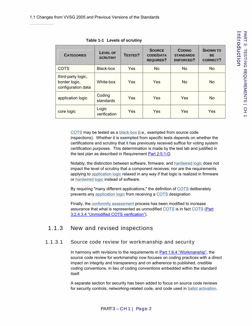
1.1 Changes from VVSG 2005 and Previous Versions of the Standards
PART 3 – CH 1 | Page 2
PART 3: T
ESTIN
G R
EQ
UIR
EM
EN
TS | C
H 1
Intro
ductio
n
Table 1-1 Levels of scrutiny
CATEGORIES LEVEL OF SCRUTINY TESTED?
SOURCE CODE/DATA REQUIRED?
CODING STANDARDS ENFORCED?
SHOWN TO BE
CORRECT?
COTS Black-box Yes No No No
third-party logic, border logic, configuration data
White-box Yes Yes No No
application logic Coding standards Yes Yes Yes No
core logic Logic verification Yes Yes Yes Yes
COTS may be tested as a black-box (i.e., exempted from source code inspections). Whether it is exempted from specific tests depends on whether the certifications and scrutiny that it has previously received suffice for voting system certification purposes. This determination is made by the test lab and justified in the test plan as described in Requirement Part 2:5.1-D.
Notably, the distinction between software, firmware, and hardwired logic does not impact the level of scrutiny that a component receives; nor are the requirements applying to application logic relaxed in any way if that logic is realized in firmware or hardwired logic instead of software.
By requiring "many different applications," the definition of COTS deliberately prevents any application logic from receiving a COTS designation.
Finally, the conformity assessment process has been modified to increase assurance that what is represented as unmodified COTS is in fact COTS (Part 3:2.4.3.4 “Unmodified COTS verification”).
1.1.3 New and revised inspections
1.1.3.1 Source code review for workmanship and security
In harmony with revisions to the requirements in Part 1:6.4 “Workmanship”, the source code review for workmanship now focuses on coding practices with a direct impact on integrity and transparency and on adherence to published, credible coding conventions, in lieu of coding conventions embedded within the standard itself.
A separate section for security has been added to focus on source code reviews for security controls, networking-related code, and code used in ballot activation.

1.1 Changes from VVSG 2005 and Previous Versions of the Standards
PART 3 – CH 1 | Page 3
PART 3: T
ESTIN
G R
EQ
UIR
EM
EN
TS | C
H 1
Intro
ductio
n
1.1.3.2 Logic verification
This version of the VVSG adds logic verification to the testing campaign to achieve a higher level of assurance that the system will count votes correctly.
Traditionally, testing methods have been divided into black-box and white-box test design. Neither method has universal applicability; they are useful in the testing of different items.
Black-box testing is usually described as focusing on testing functional requirements, these requirements being defined in an explicit specification. It treats the item being tested as a "black-box," with no examination being made of the internal structure or workings of the item. Rather, the nature of black-box testing is to develop and utilize detailed scenarios, or test cases. These test cases include specific sets of input to be applied to the item being tested. The output produced by the given input is then compared to a previously defined set of expected results.
White-box testing (sometimes called clear-box or glass-box testing to suggest a more accurate metaphor) allows one to peek inside the "box," and focuses specifically on using knowledge of the internals of the item being tested to guide the testing procedure and the selection of test data. White-box testing can discover extra non-specified functions that black-box testing would not know to look for and can exercise data paths that would not have been exercised by a fixed test suite. Such extras can only be discovered by inspecting the internals.
Complementary to any kind of operational testing is logic verification, in which it is shown that the logic of the system satisfies certain constraints. When it is impractical to test every case in which a failure might occur, logic verification can be used to show the correctness of the logic generally. However, verification is not a substitute for testing because there can be faults in a proof just as surely as there can be faults in a system. Used together, testing and verification can provide a high level of assurance that a system's logic is correct.
A commonly raised objection to logic verification is the observation that, in the general case, it is exceedingly difficult and often impractical to verify any nontrivial property of software. This is not the general case. While these Guidelines try to avoid constraining the design, all voting system designs must preserve the ability to demonstrate that votes will be counted correctly. If a voting system is designed in such a way that it cannot be shown to count votes correctly, then that voting system does not satisfy Requirement Part 1:6.1-B.
1.1.4 New and revised test methods
1.1.4.1 End-to-End testing
The testing specified in [VSS2002] and [VVSG2005] is not required to be end-to-end but may bypass portions of the system that would be exercised during an actual election ([VVSG2005] II.1.8.2.3).
1.1 Changes from VVSG 2005 and Previous Versions of the Standards
PART 3 – CH 1 | Page 4
PART 3: T
ESTIN
G R
EQ
UIR
EM
EN
TS | C
H 1
Intro
ductio
n
The use of text fixtures that bypass portions of the system may lower costs and/or increase convenience, but the validity of the resulting testing is difficult to defend. If a discrepancy arose between the results reported by test labs and those found in state acceptance tests, it would likely be attributable to this practice.
Language permitting the use of simulation devices to accelerate the testing process has been tightened to prohibit bypassing portions of the voting system that would be exercised in an actual election, with few exceptions (Part 3:2.5.3 “Test fixtures”), and a volume test analogous to the California Volume Reliability Testing Protocol [CA06] has been specified (Requirement Part 3:5.2.3-D).
1.1.4.2 Reliability, accuracy, and probability of misfeed
Previous versions of these Guidelines specified a Probability Ratio Sequential Test [Wald47][Epstein55][MIL96] for assessment of reliability and accuracy. No test was specified for assessment of probability of misfeed, though it would have been analogous.
The Probability Ratio Sequential Tests for reliability and accuracy ran concurrent with the temperature and power variation test. There was no specified way to assess errors and failures observed during other portions of the test campaign.
Reliability, accuracy, and probability of misfeed are now assessed using data collected through the course of the entire test campaign. This increases the amount of data available for assessment of conformity to these performance requirements without necessarily increasing the duration of testing.
1.1.4.3 Open-ended vulnerability testing
This version adds Open Ended Vulnerability Testing (OEVT) as a test method. OEVT is akin to vulnerability penetration testing, conducted by a team of testers in an open-ended fashion not necessarily constrained with a test script. The goal of OEVT is to discover architecture, design and implementation flaws in the system that may not be detected using systematic functional, reliability, and security testing and which may be exploited to change the outcome of an election, interfere with voters’ ability to cast ballots or have their votes counted during an election or compromise the secrecy of vote.
OEVT is generally not called out in Test reference: fields; the assumption is that any requirement in the VVSG or aspect of voting system operations is “fair game” for OEVT. In particular, OEVT should be useful for testing those requirements that require source code inspection as a test method.

2.1 Overview
PART 3 – CH 2 | Page 5
PART 3: T
ESTIN
G R
EQ
UIR
EM
EN
TS | C
H 2
Confo
rmity A
ssessmen
t Process
Chapter 2: Conformity Assessment Process
2.1 Overview
Conformity assessment encompasses the examination and testing of software and firmware; tests of hardware under conditions simulating the intended storage, operation, transportation, and maintenance environments; inspection and evaluation of system documentation; and operational tests to validate system performance and functioning under normal and abnormal conditions. Conformity assessment also evaluates the completeness of the manufacturer's developmental test program, including the sufficiency of manufacturer tests conducted to demonstrate compliance with stated system design and performance specifications, and the manufacturer's documented quality assurance and configuration management practices. The assessment addresses individual system components or elements as well as the integrated system as a whole.
Beginning in 1994, the National Association of State Election Directors (NASED) began accrediting Independent Test Authorities for the purpose of conducting qualification testing of voting systems. The qualification testing process was originally based on the 1990 voting system standards and evolved to encompass the new requirements contained in the 2002 version of the standards.
The Help America Vote Act (HAVA) directs the U.S. Election Assistance Commission (EAC) to provide for the testing, certification, decertification, and recertification of voting system hardware and software by accredited laboratories. HAVA also introduces different terminology for these functions. Under the EAC process, test labs are "accredited" and voting systems are "certified." The term "standards" has been replaced with the term "VVSG."
Conformity assessment may be performed by one or more accredited test labs that together perform the full scope of tests required. Assessment may be coordinated across accredited test labs so that equipment and materials tested by one accredited test lab can be used in the tests performed by another accredited test lab.
When multiple accredited test labs are being used, the development of the test plan (see Part 2:Chapter 5: “Test Plan (test lab)”) and the test report (see Part 2:Chapter 6: ”Test Report (test lab)”) must be coordinated by a lead accredited test lab. The lead test lab is responsible for ensuring that all testing has been performed and documented in accordance with the VVSG and is ultimately responsible for the summary finding of conformance (see Requirement Part 2:6.1-F).
Whether one or more accredited test labs are used, the testing generally consists of three phases:
♦ Pre-test activities;

2.2 Scope of Assessment
PART 3 – CH 2 | Page 6
PART 3: T
ESTIN
G R
EQ
UIR
EM
EN
TS | C
H 2
Confo
rmity A
ssessmen
t Process
♦ Testing; and
♦ Post-test activities.
2.2 Scope of Assessment
The conformity assessment process is intended to discover vulnerabilities that, should they appear in actual election use, could result in failure to complete election operations in a satisfactory manner. This involves
♦ Operational accuracy in the recording and processing of voting data, as measured by report total error rate;
♦ Operational failures or the number of unrecoverable failures under conditions simulating the intended storage, operation, transportation, and maintenance environments for voting systems;
♦ System performance and function under normal and abnormal conditions; and
♦ Completeness and accuracy of the system documentation and configuration management records to enable purchasing jurisdictions to effectively install, test, and operate the system.
Conformity assessment involves several different kinds of testing, including
♦ Inspections, where the conformity of the voting system and manufacturer practices for configuration management and quality assurance are evaluated via expert review;
♦ Hardware testing, where the ability of the system to tolerate the physical conditions of its operation, transportation and storage is evaluated;
♦ Functional testing, where the conformity of the voting system's observable behaviors is evaluated;
♦ Performance testing, where the satisfaction of specified benchmarks is either evaluated in specific tests or monitored concurrent with other testing;
♦ Usability testing, where the performance is evaluated with human test subjects; and
♦ Vulnerability testing, where the system's resistance to attack is evaluated.
Voting system hardware, software, communications and documentation are examined and tested to determine suitability for elections use. Examination and testing address the broad range of system functionality and components, including system functionality for pre-voting, voting, and post-voting functions. All products for election use are tested in accordance with the applicable procedures.
Tests are conducted for new systems seeking initial testing as well as for modified versions of systems that have been previously tested.

2.3 Testing Sequence
PART 3 – CH 2 | Page 7
PART 3: T
ESTIN
G R
EQ
UIR
EM
EN
TS | C
H 2
Confo
rmity A
ssessmen
t Process
Not all systems are required to complete every category of testing. Consistent with Requirement Part 2:5.1-D, the test lab may find that proven performance of COTS hardware, software and communications components in commercial applications other than elections obviates the need for certain specific evaluations. However, as most functional testing exercises the complete system, COTS components are always tested together with other components of the voting system. Similarly, if a previous version of the same system has been tested, the test lab may find that complete retesting would be redundant, but some tests that exercise the entire system are always conducted. The background and rationale for these decisions regarding the scope of testing must be documented in the test plan.
The accredited test lab determines which tests are necessary to reassess a modified system based on a review of the nature and scope of changes and other submitted information including the system documentation, manufacturer test documentation, configuration management records, and quality assurance information. The accredited test lab may determine that a modified system is subject only to limited retesting if the manufacturer demonstrates that the change does not affect demonstrated compliance with these VVSG for:
♦ Performance of voting system functions;
♦ Voting system security and privacy;
♦ Overall flow of system control; and
♦ The manner in which ballots are defined and interpreted, or voting data are processed.
Limited testing is intended to facilitate the correction of defects, the incorporation of improvements, the enhancement of portability and flexibility, and the integration of vote counting software with other systems and election software.
In all cases, the system documentation and configuration management records are examined to confirm that they completely and accurately reflect the components and component versions that comprise the voting system.
2.3 Testing Sequence
Tests and inspections required by these VVSG need not be conducted in any particular order. Test labs should organize the test campaign to maximize overall testing effectiveness, to test in as efficient a manner as possible, and to minimize the amount of regression testing that is incurred when nonconformities are found and corrected. Test anomalies and errors are communicated to the system manufacturer throughout the process.
2.4 Pre-Test Activities
Pre-test activities include the request for initiation of testing and the pre-test preparation.
2.4 Pre-Test Activities
PART 3 – CH 2 | Page 8
PART 3: T
ESTIN
G R
EQ
UIR
EM
EN
TS | C
H 2
Confo
rmity A
ssessmen
t Process
2.4.1 Initiation of testing
Conformity assessment is conducted at the request of the manufacturer. The manufacturer must:
♦ Request the performance of conformity assessment from among the accredited testing laboratories;
♦ Enter into formal agreement with the accredited test lab for the performance of testing; and
♦ Prepare and submit materials required for testing consistent with the requirements of the VVSG.
Conformity assessment is conducted for the initial version of a voting system as well as for all subsequent revisions to the system that are to be used in elections. As described in Part 3:2.2 “Scope of Assessment”, the nature and scope of testing for system changes or new versions is determined by the accredited test lab based on the nature and scope of the modifications to the system and on the quality of system documentation and configuration management records submitted by the manufacturer.
2.4.2 Pre-test preparation
Pre-test preparation encompasses the following activities:
♦ The manufacturer and accredited test lab enter into an agreement for the testing to be performed by the accredited test lab;
♦ The manufacturer prepares and submits a TDP to the accredited test lab. The TDP consists of the materials described in Part 2:Chapter 3: ”Technical Data Package (manufacturer)”;
♦ The accredited test lab performs an initial review of the TDP for completeness and clarity and requests additional information as required;
♦ The manufacturer provides additional information if requested by the accredited test lab;
♦ The test lab witnesses the production of the implementation for testing;
♦ The manufacturer delivers to the accredited test lab all hardware and software needed to perform testing.
2.4.2.1 Documentation submitted by manufacturer
2.4.2.1-A Submit Technical Data Package
The manufacturer SHALL submit to the test lab a Technical Data Package conforming to the requirements of Part 2:Chapter 3: ”Technical Data Package (manufacturer)”.
Applies to: Voting system
2.4 Pre-Test Activities
PART 3 – CH 2 | Page 9
PART 3: T
ESTIN
G R
EQ
UIR
EM
EN
TS | C
H 2
Confo
rmity A
ssessmen
t Process
D I S C U S S I O N
The manufacturer must submit all the documentation necessary for the identification of the full system configuration submitted for evaluation and for the development of an appropriate test plan by the accredited test lab for conducting conformity assessment. This documentation collectively is referred to as the Technical Data Package (TDP). The TDP provides information that defines the voting system's design, method of operation, and related resources. It provides a system overview and documents the system's functionality, hardware, software, security, test specifications, operations procedures, maintenance procedures, and personnel deployment and training requirements. It also documents the manufacturer's configuration management plan and quality assurance program. If another version of the system was previously tested, the TDP would also include appropriate system change notes.
Source: [VVSG2005] II.1.5
2.4.2.2 Voting equipment submitted by manufacturer
Manufacturers may seek to market a complete voting system or an interoperable component of a voting system. In all instances, manufacturers must submit for testing the specific system configuration that will be offered to jurisdictions or that comprises the component to be marketed plus the other components with which the component is to be used. Under no circumstances will a component be assessed except as part of a complete voting system, and that assessment is valid only when that component is used with that same system (see Part 1:2.3 “Conformance Designations”).
2.4.2.2-A Submit system without COTS
If needed for compliance with Part 3:2.4.3.4 “Unmodified COTS verification”, the manufacturer SHALL supply the system with the COTS components omitted, for subsequent integration performed by or witnessed by the test lab.
Applies to: Voting system
D I S C U S S I O N
See Part 3:2.4.3.4 “Unmodified COTS verification”.
Source: New requirement.
2.4.2.2-B Hardware equivalent to production version
The hardware submitted for conformity assessment SHALL be equivalent, in form and function, to the actual production version of the hardware units specified for use in the TDP.
Applies to: Voting system
Source: [VVSG2005] II.1.6.a

2.4 Pre-Test Activities
PART 3 – CH 2 | Page 10
PART 3: T
ESTIN
G R
EQ
UIR
EM
EN
TS | C
H 2
Confo
rmity A
ssessmen
t Process
2.4.2.2-C Logic equivalent to production version
The firmware and software submitted for conformity assessment SHALL be the exact firmware and software that will be used in production units.
Applies to: Voting system
Source: [VVSG2005] II.1.6.b
2.4.2.2-D No prototypes
Developmental prototypes SHALL NOT be submitted unless the manufacturer can show that the equipment to be tested is equivalent to standard production units both in performance and construction.
Applies to: Voting system
Source: [VVSG2005] II.1.6.c
2.4.2.2-E Benchmark directory listings
Benchmark directory listings SHALL be submitted for all software/firmware elements (and associated documentation) included in the manufacturer's release as they would normally be installed upon setup and installation.
Applies to: Voting system
Source: [VVSG2005] II.1.6.d
2.4.3 Initial system build by test lab
The following requirements describe how test labs are to perform build of voting system software by the test lab.
Previously built voting system software being updated may be able to use the requirements found Part 3:2.4.3.3 “Updating previously built voting system software executable code” to create the updated executable code including application logic, border logic, and third party logic.
2.4.3.1 Build environment establishment
2.4.3.1-A Test lab build environment assembly
The test lab SHALL assemble the build environment(s) used to create executable code including application logic, border logic, and third party logic.
Applies to: Voting system
Source: [EAC06] Section 5.6.1.2 and [VVSG2005] II.1.8.2.4
2.4 Pre-Test Activities
PART 3 – CH 2 | Page 11
PART 3: T
ESTIN
G R
EQ
UIR
EM
EN
TS | C
H 2
Confo
rmity A
ssessmen
t Process
2.4.3.1-A.1 Witness of build environment assembly
At least one representative from the manufacturer SHALL witness the assembly of the build environment.
Applies to: Voting system
Source: [EAC06] Section 5.6 and [VVSG2005] II.1.8.2.4
2.4.3.1-A.2 Build environment establishment record
A representative from the test lab SHALL create a build environment establishment record that includes at a minimum: a unique identifier (such as a serial number) for the record; a list of unique identifiers of unalterable storage media associated with the record; the time, date, and location the build environment was established; names, affiliations, and signatures of all people present; copies of the procedures used to assemble the build environment; list of software and hardware used to establish the build environment; and the voting system associated with the build environment.
Applies to: Voting system
Source: [EAC06] Section 5.9
2.4.3.1-A.3 Build environment software and hardware procurement
The test lab SHALL obtain the software and hardware required to establish the build environment.
Applies to: Voting system
D I S C U S S I O N
Requirement Part 2:3.5.4-C documents the software and hardware required to assemble the build environment.
2.4.3.1-A.4 Open market procurement of COTS software and hardware
The test lab SHALL obtain COTS software and hardware required to assemble the build environment from the open market.
Applies to: Voting system
D I S C U S S I O N
Note: manufacturers are required to supply non-COTS hardware and software as part of Requirement Part 3:2.4.2.2-A.
2.4.3.1-A.5 Erasable storage media preparation
The test lab SHALL remove any previously stored information on erasable storage media in preparation for using the media to assemble the build environment.
Applies to: Voting system
2.4 Pre-Test Activities
PART 3 – CH 2 | Page 12
PART 3: T
ESTIN
G R
EQ
UIR
EM
EN
TS | C
H 2
Confo
rmity A
ssessmen
t Process
D I S C U S S I O N
The purpose of this requirement is to prepare erasable storage media for use by the build environment. The requirement does not require the prevention of previously stored information leakage or recovery. Simply deleting files from file systems, flashing memory cards, and removing electrical power from volatile memory satisfies this requirement.
Source: [EAC06] Section 5.6.1.1
2.4.3.1-A.6 Build environment assembly
The test lab SHALL use the procedures found in the TDP to assemble the build environment.
Applies to: Voting system
D I S C U S S I O N
Requirement Part 2:3.5.4-D documents the procedures to assemble the build environment. Test lab personnel can have manufacturers provide guidance during the assembly of the build environment, but test lab personnel must perform the actual assembly.
Source: [EAC06] Section 5.6.1.2
2.4.3.1-A.7 Build environment assembly deviation record requirement
The test lab SHALL document as part of the build environment establishment record the reason for any deviation from assembly procedures found in the TDP.
Applies to: Voting system
D I S C U S S I O N
Requirement Part 2:3.5.4-D documents the procedures used to assemble the build environment.
Source: [EAC06] Section 5.9
2.4.3.1-A.8 Build environment digital signature verification
When digital signatures are associated with software, the test lab SHALL verify digital signatures before using the software for the build environment.
Applies to: Voting system
D I S C U S S I O N
The digital signatures associated with the build environment may be from the manufacturer of the software, National Software Reference Library (NSRL), or other authoritative sources.
Source: [EAC06] Section 5.6.2.1

2.4 Pre-Test Activities
PART 3 – CH 2 | Page 13
PART 3: T
ESTIN
G R
EQ
UIR
EM
EN
TS | C
H 2
Confo
rmity A
ssessmen
t Process
2.4.3.1-A.9 Build environment digital signature verification record
The test lab SHALL record as part of the build environment establishment record the results of digital signature verification including who generated the signature.
Applies to: Voting system
Source: [EAC06] Section 5.9
2.4.3.1-A.10 Build environment pre-build binary image copy
The test lab SHALL copy the binary image of the assembled build environment to unalterable storage media.
Applies to: Voting system
D I S C U S S I O N
This requirement creates a snapshot of the build environment before it is used to build the voting system software executable code. Unalterable storage media includes technology such as a CD-R, but not CD-RW.
2.4.3.1-A.11 Build environment pre-build binary image digital signature
The test lab SHALL create a digital signature for the binary image of the build environment, and include the digital signature on the unalterable storage media with the binary image.
Applies to: Voting system
Source: [EAC06] Section 5.6.1.3
2.4.3.2 Build of voting system software executable code
Previously built voting system software being updated may be able to use Requirement Part 3:2.4.3.3 to create the updated executable code including application logic, border logic, and third party logic.
2.4.3.2-A Use of established build environment
The test lab SHALL build the executable code including application logic, border logic, and third party logic of the voting system using the established build environment.
Applies to: Voting system
D I S C U S S I O N
The build environment is established using the requirements in Part 3:2.4.3.1 “Build environment establishment”.
Source: [EAC06] and [VVSG2005] II.1.8.2.4
2.4 Pre-Test Activities
PART 3 – CH 2 | Page 14
PART 3: T
ESTIN
G R
EQ
UIR
EM
EN
TS | C
H 2
Confo
rmity A
ssessmen
t Process
2.4.3.2-A.1 Witness of voting system software build
At least one representative from the manufacturer SHALL witness the build of executable code including application logic, border logic, and third party logic of the voting system.
Applies to: Voting system
Source: [EAC06] Section 5.6
2.4.3.2-A.2 Voting system software build record
A representative from the test lab SHALL create an executable code build record that includes at a minimum: a unique identifier (such as a serial number) for the record; a list of unique identifiers of unalterable storage media associated with the record; the time, date, and location of the build; names, affiliations, and signatures of all people present; filenames of the source code and resulting executable code; voting system software version; name and version of the voting system (including certification number, if possible); and copies of the procedures used to build the voting system software executable code.
Applies to: Voting system
Source: [EAC06] Section 5.9
2.4.3.2-A.3 Voting system software digital signature verification
The test lab SHALL validate manufacturer digital signatures on voting system software source code before placing source code on the build environment.
Applies to: Voting system
D I S C U S S I O N
Requirement Part 3:2.6.2.4-D requires manufacturers to provide voting system software source code with digital signatures as part of the TDP.
Source: [EAC06] Section 5.6.2.1
2.4.3.2-A.4 Voting system software digital signature verification result record
The results of digital signature validation including who generated the signature SHALL be part of the executable code build record for voting system software.
Applies to: Voting system
Source: [EAC06] Section 5.9
2.4 Pre-Test Activities
PART 3 – CH 2 | Page 15
PART 3: T
ESTIN
G R
EQ
UIR
EM
EN
TS | C
H 2
Confo
rmity A
ssessmen
t Process
2.4.3.2-A.5 Voting system software build
The test lab SHALL use the procedures found in the TDP to build the voting system software executable code including application logic, border logic, and third party logic.
Applies to: Voting system
D I S C U S S I O N
Requirement Part 2:3.5.4-E documents the procedures to build voting system software executable code. Test lab personnel can have manufacturers provide guidance during the build of the voting system executable code, but test lab personnel must perform the actual build.
Source: [EAC06] Section 5.6.3
2.4.3.2-A.6 Voting system software executable code build deviation record
The test lab SHALL document as part of the executable code build record the reason for any deviation from build procedures found in the TDP.
Applies to: Voting system
D I S C U S S I O N
Requirement Part 2:3.5.4-E documents the procedures to build voting system software executable code.
Source: [EAC06] Section 5.9
2.4.3.2-A.7 Build environment post build binary image
After voting system software executable code including application logic, border logic, and third party logic has been built, the test lab SHALL copy the binary image of the build environment (including source and executable code) to unalterable storage media.
Applies to: Voting system
D I S C U S S I O N
This requirement creates a snapshot of the build environment after it has been used to build voting system software executable code. Unalterable storage media includes technology such as a CD-R, but not CD-RW.
Source: [EAC06] Section 5.6.2.3
2.4.3.2-A.8 Build environment post build binary image digital signature
After voting system software executable code including application logic, border logic, and third party logic has been built, the test lab SHALL create a digital signature for the binary image of the build environment (including source and executable code), and include the digital signature on the unalterable storage media with the binary image.
Applies to: Voting system

2.4 Pre-Test Activities
PART 3 – CH 2 | Page 16
PART 3: T
ESTIN
G R
EQ
UIR
EM
EN
TS | C
H 2
Confo
rmity A
ssessmen
t Process
Source: [EAC06] Section 5.6.2.2
2.4.3.3 Updating previously built voting system software executable code
The following voting system software build requirements apply when updates to previously built voting system software has occurred. These requirements assume the original build environment can be used to create the updated software and a significant portion of original software is not being updated. If the original build environment cannot be used or a significant portion of the original software is being updated, then the requirements of Part 3:2.4.3.1 “Build environment establishment” and Part 3:2.4.3.2 ”Build of voting system software executable code”.
2.4.3.3-A Witness of build for previously built voting system software
At least one representative from the manufacturer SHALL witness the establishment of the post build environment associated with the previously built voting system software, and the build of the updated voting system software executable code including application logic, border logic, and third party logic.
Applies to: Voting system
D I S C U S S I O N
This requirement does not modify the requirement found in Section 5.6 of the EAC Testing and Certification Program Manual [EAC06] requiring a representative from both the manufacturer and test lab to be present during the build
Source: [EAC06] Section 5.6
2.4.3.3-B Original post build environment re-establishment
The test lab SHALL establish the build environment using the original post build environment binary image associated with the previously built voting system software.
Applies to: Voting system
D I S C U S S I O N
Requirements Part 3:2.4.3.2-A.7 and Part 3:2.4.3.2-A.8 create the post build binary image of the original built voting system software developed by the manufacturer. If the test lab does not posses the required hardware and software to create the build environment then Requirements Part 3:2.4.3.2-A.7 and Part 3:2.4.3.2-A.8 apply. This requirement extends the requirement found in [EAC06] Section 5.6.4.1 and 5.6.4.2 by explicitly stating the original build environment needs to be established
Source: [EAC06] Section 5.6.4.1 and 5.6.4.2
2.4 Pre-Test Activities
PART 3 – CH 2 | Page 17
PART 3: T
ESTIN
G R
EQ
UIR
EM
EN
TS | C
H 2
Confo
rmity A
ssessmen
t Process
2.4.3.3-B.1 Erasable storage media preparation
The test lab SHALL remove previously stored information on erasable storage media in preparation for using the media to establish the build environment.
Applies to: Voting system
D I S C U S S I O N
The purpose of this requirement is to prepare the erasable storage media for use by the original post build environment. The requirement does not require the prevention of previously stored information leakage or recovery. Simply deleting files from the file system, flash memory cards, and removing electrical power from volatile memory satisfy this requirement
Source: [EAC06] Section 5.6.1.1
2.4.3.3-B.2 Original post build environment re-establishment digital signature
verification
The test lab SHALL verify the digital signature of the original post build binary image associated with the previously built voting system software before using the binary image to establish the build environment.
Applies to: Voting system
D I S C U S S I O N
This requirement does not modify the requirement found in Section 5.6.4.1 of the EAC Testing and Certification Program Manual [EAC06] that states the file signature of the build environment needs to be verified before use.
Source: [EAC06] Section 5.6.4.1
2.4.3.3-B.3 Original post build environment re-establishment digital signature
verification record
The result of digital signature verification including who generated the signature SHALL be part of the original post build environment establishment record.
Applies to: Voting system
Source: [EAC06] Section 5.9
2.4.3.3-B.4 Original post build environment re-establishment record
A representative from the test lab SHALL create an original post build environment establishment record that includes at a minimum: a unique identifier (such as a serial number) for the record; a list of unique identifiers of unalterable storage media associated with the record; the time, date, and location the original post build environment was established; names,

2.4 Pre-Test Activities
PART 3 – CH 2 | Page 18
PART 3: T
ESTIN
G R
EQ
UIR
EM
EN
TS | C
H 2
Confo
rmity A
ssessmen
t Process
affiliations, and signatures of all people present; copies of the procedures used to assemble the original post build environment; list of software and hardware used to establish the original post build environment; and the voting system associated with the original post build environment.
Applies to: Voting system
D I S C U S S I O N
This requirement updates the requirement found in Section 5.9 of the EAC Testing and Certification Program Manual [EAC06] by specifying the information needed to be documented when establishing the build environment.
Source: [EAC06] Section 5.9
2.4.3.3-C Build of updated voting system software executable code
The test lab SHALL build the executable code including application logic, border logic, and third party logic of the updated voting system software.
Applies to: Voting system
D I S C U S S I O N
This requirement does not modify the requirement found in Section 5.6.4.2 of the EAC Testing and Certification Program Manual [EAC06] that states the executable files are created; and extends the requirement found at Section 1.8.2.4 of [VVSG2005] Volume II in [VVSG2005] by requiring the use of the build environment established in Part 3:2.4.3.1 “Build environment establishment”.
Source: [EAC06] Section 5.6.4.2 and [VVSG2005] II.1.8.2.4
2.4.3.3-C.1 Updated voting system software source code digital signature
verification
The test lab SHALL validate manufacturer digital signatures on updated voting system software source code before placing the updated source code on the build environment.
Applies to: Voting system
D I S C U S S I O N
This requirement modifies the requirement found in Section 5.6.4.2 of the EAC Testing and Certification Program Manual [EAC06] by constraining the verification to digital signature from a “file signature” (which could be a hash value or digital signature); extends 5.6.2.1 by specifying the verification to happen before software is installed on the build environment; and does not call for the digital signature of the build environment to be verified before installing the source code.
Source: [EAC06] Section 5.6.4.2
2.4 Pre-Test Activities
PART 3 – CH 2 | Page 19
PART 3: T
ESTIN
G R
EQ
UIR
EM
EN
TS | C
H 2
Confo
rmity A
ssessmen
t Process
2.4.3.3-C.2 Updated voting system software source code digital signature
verification record
The result of digital signature verification including who generated the signature SHALL be part of the updated voting system software build record.
Applies to: Voting system
D I S C U S S I O N
Requirement Part 3:2.6.2.4-D requires manufacturers to provide voting system software source code with digital signatures as part of the TDP. This requirement updates the requirement found in Section 5.9 of the EAC Testing and Certification Program Manual [EAC06] by specifying the results of digital signature verification needs to be documented as part of the record when building the executable code.
Source: [EAC06] Section 5.9
2.4.3.3-C.3 Updated voting system software build procedures
The test lab SHALL use the procedures found in the TDP to build the updated voting system software executable code including application logic, border logic, and third party logic.
Applies to: Voting system
D I S C U S S I O N
Requirement Part 2:3.5.4-G documents the procedures to build the updated voting system software executable code. Test labs can have manufacturers assist in building of the updated voting system software executable code. This requirement extends the requirement found in Section 5.6.4.2 of the [EAC06] by specifying the use of the manufacturer supplied procedures to build the updated voting system software.
Source: [EAC06] Section 5.6.4.2
2.4.3.3-C.4 Updated voting system software build record
A representative from the test lab SHALL create an executable code build record that includes at a minimum: a unique identifier (such as a serial number) for the record; a list of unique identifiers of unalterable storage media associated with the record; the time, date, and location of the build; names, affiliations, and signatures of all people present; filenames of the source code and resulting executable code; voting system software version; name and version of the voting system (including certification number, if possible); and copies of the procedures used to build the updated voting system software executable code.
Applies to: Voting system
2.4 Pre-Test Activities
PART 3 – CH 2 | Page 20
PART 3: T
ESTIN
G R
EQ
UIR
EM
EN
TS | C
H 2
Confo
rmity A
ssessmen
t Process
D I S C U S S I O N
This requirement updates the requirement found in Section 5.9 of the [EAC06] by specifying the information needed to be documented when creating updated executable code.
Source: [EAC06] Section 5.9
2.4.3.3-C.5 Updated build environment post build binary image
After updated voting system software executable code including application logic, border logic, and third party logic has been built, the test lab SHALL copy the binary image of the updated build environment (including source and executable code) to unalterable storage media.
Applies to: Voting system
D I S C U S S I O N
This requirement creates a snapshot of the updated build environment after it has been used to build the updated voting system software executable code. Unalterable storage media includes technology such as a CD-R, but not CD-RW. This requirement differs from the requirement found in Section 5.6.2.3 of the [EAC06] by creating the binary image after, instead of before, the updated software executable code has been built.
Source: [EAC06] Section 5.6.2.3
2.4.3.3-C.6 Updated build environment post build binary image digital signature
After updated voting system software executable code including application logic, border logic, and third party logic has been built, the test lab SHALL create a digital signature for the binary image of the updated build environment (including source and executable code), and include the digital signature on the unalterable storage media with the binary image.
Applies to: Voting system
D I S C U S S I O N
This requirement differs from the requirement found in Section 5.6.2.2 of the [EAC06] by creating a digital signature on the binary image after the software executable code has been built as opposed to a “file signature” which could be a hash value or digital signature before the software executable code is built; although requirement 5.6.3.1 of the EAC Testing and Certification Program Manual requires “file signatures” for updated executable code.
Source: [EAC06] Section 5.6.2.2
2.4.3.4 Unmodified COTS verification
The following requirements describe how test labs are to verify that products identified as COTS are unmodified when used by the voting system.

2.4 Pre-Test Activities
PART 3 – CH 2 | Page 21
PART 3: T
ESTIN
G R
EQ
UIR
EM
EN
TS | C
H 2
Confo
rmity A
ssessmen
t Process
2.4.3.4-A COTS assembly and configuration documentation
The manufacturer SHALL document the procedures used to assemble and configure unmodified COTS components into the system supplied in Requirement Part 3:2.4.2.2-A.
Applies to: Voting system
D I S C U S S I O N
Test labs will assemble and configure unmodified COTS components into the voting system using the documentation provided by this requirement. Requirement Part 2:4.4.1-A subitem e identifies all COTS components in the voting system, and Requirement Part 2:3.8-D requires configuration data for unmodified COTS to be documented.
Source: COTS verification process per STS and CRT consensus, June 2006
2.4.3.4-B Obtain COTS Off the shelf
Test labs SHALL obtain COTS components identified in Requirement Part 2:4.4.1-A subitem 5 from open market suppliers of COTS components.
Applies to: Voting system
D I S C U S S I O N
Test labs will procure the COTS components “off-the-shelf” from suppliers of the COTS components.
2.4.3.4-C COTS assembly and configuration witness
At least one representative from the test lab and manufacturer SHALL witness the assembly and configuration of the COTS components into the voting system.
Applies to: Voting system
2.4.3.4-C.1 Test lab assembly and configuration of COTS
The test lab SHALL assemble and configure the COTS components into the voting system.
Applies to: Voting system
2.4.3.4-C.2 Test lab record of COTS assembly and configuration
The test lab SHALL document and maintain a record of the COTS assembly and configuration that includes, at a minimum: a unique identifier for each record; the time and date and location of the voting system build; names, affiliations, and signatures of all people present; copies of the procedures used to assemble and configure the COTS components; and identification of the voting system.

2.5 Testing
PART 3 – CH 2 | Page 22
PART 3: T
ESTIN
G R
EQ
UIR
EM
EN
TS | C
H 2
Confo
rmity A
ssessmen
t Process
Applies to: Voting system
2.4.3.4-C.3 Document deviations from of COTS assembly and configuration
documentation
The test lab SHALL document deviations from the manufacturer documentation submitted for assembly and configuration of the COTS components.
Applies to: Voting system
2.5 Testing
Testing encompasses the preparation of a test plan, the establishment of the appropriate test conditions, the use of appropriate test fixtures, the witness of the system build and installation, the maintenance of test data, and the evaluation of the data resulting from tests and examinations.
2.5.1 Test plan
2.5.1-A Prepare test plan
The accredited test lab SHALL prepare a test plan to define all tests and procedures required to assess conformity to the VVSG, including:
a. Verifying or checking equipment operational status by means of manufacturer operating procedures;
b. Establishing the test environment or the special environment required to perform each test;
c. Initiating and completing operating modes or conditions necessary to evaluate the specific performance characteristics under test;
d. Measuring and recording the value or range of values for the characteristics to be tested, demonstrating expected performance levels;
e. Verifying, as above, that the equipment is still in normal condition and status after all required measurements have been obtained;
f. Confirming that documentation submitted by the manufacturer corresponds to the actual configuration and operation of the system; and
g. Confirming that documented manufacturer practices for quality assurance and configuration management comply with the VVSG.
Applies to: Voting system
D I S C U S S I O N
Requirements on the content of the test plan are contained in Part 2:Chapter 5: ”Test Plan (test lab)”.
Source: [VVSG2005] II.1.8.2.1

2.5 Testing
PART 3 – CH 2 | Page 23
PART 3: T
ESTIN
G R
EQ
UIR
EM
EN
TS | C
H 2
Confo
rmity A
ssessmen
t Process
2.5.2 Test conditions
The accredited test lab may perform the tests in any facility capable of supporting the test environment.
2.5.2-A Witness test preparation
Preparations for testing, arrangement of equipment, verification of equipment status, and the execution of procedures SHALL be witnessed by at least one independent, qualified observer, who SHALL attest that all test and data acquisition requirements have been satisfied.
Applies to: Voting system
Source: [VSS2002] II.9.6.2.2.a
2.5.2-B Ambient conditions
When a test is to be performed at "standard" or "ambient" conditions, this SHALL refer to a nominal laboratory or office environment with a temperature in the range of 20.0 °C to 23.9 °C (68 °F to 75 °F) and prevailing atmospheric pressure and relative humidity.
Applies to: Voting system
Source: [VVSG2005] II.1.8.2.2.b
2.5.2-C Tolerances for specified temperatures and voltages
When a test is to be performed at conditions other than "standard" or "ambient," the test SHALL be performed at the required temperature and electrical supply voltage, regulated within the following tolerances:
a. Temperature ± 2.2 °C (± 4 °F) b. AC electrical supply voltage ± 2 V
Applies to: Voting system
Source: [VVSG2005] II.1.8.2.2.c
2.5.3 Test fixtures
2.5.3-A Complete system testing
Except as provided in Requirement Part 3:2.5.3-B, the test lab SHALL NOT use simulation devices or software that bypass portions of the voting system that would be exercised in an actual election.
Applies to: Voting system
2.5 Testing
PART 3 – CH 2 | Page 24
PART 3: T
ESTIN
G R
EQ
UIR
EM
EN
TS | C
H 2
Confo
rmity A
ssessmen
t Process
D I S C U S S I O N
Devices or software that closely and validly simulate actual election use of the system are permissible. If a tabulator is specified to count paper ballots that are manually-marked with a specific writing utensil, it is not valid to substitute ballots that were mechanically marked by a printer. However, ballots that were marked according to manufacturer instructions can sometimes be recycled through a tabulator without invalidating the test. Limitations on this practice are provided in Requirement Part 3:5.2.3-D.
2.5.3-B Exceptions to complete system testing
The test lab may bypass the user interface of an interactive device in the case of environmental tests that:
a. Would require subjecting test "voters" to unsafe or unhealthy conditions; or
b. Would be invalidated by the presence of a test "voter." Applies to: Voting system
2.5.4 Test data requirements
2.5.4-A Test log
A test log of the procedure SHALL be maintained. This log SHALL identify the system and equipment by model and serial number.
Applies to: Voting system
Source: [VVSG2005] II.1.8.2.5.a
2.5.4-B Test environment conditions
Test environment conditions SHALL be recorded.
Applies to: Voting system
Source: [VVSG2005] II.1.8.2.5.b
2.5.4-C Items to be logged
All operating steps, the identity and quantity of simulated ballots, annotations of output reports, the elapsed time for each procedure step, observations of equipment performance, and, in the case of non-operating hardware tests, the condition of the equipment SHALL be recorded.
Applies to: Voting system
Source: [VVSG2005] II.1.8.2.5.c
2.5 Testing
PART 3 – CH 2 | Page 25
PART 3: T
ESTIN
G R
EQ
UIR
EM
EN
TS | C
H 2
Confo
rmity A
ssessmen
t Process
2.5.5 Test practices
2.5.5-A Conduct all tests
The accredited test lab SHALL conduct the examinations and tests defined in the test plan to determine compliance with the voting system requirements described in Part 1 and Part 2.
Applies to: Voting system
Source: [VVSG2005] II.1.8.2.6
2.5.5-B Log all anomalies
If any failure, malfunction or data error is detected, its occurrence and the duration of operating time preceding it SHALL be recorded for inclusion in the analysis of data obtained from the test.
Applies to: Voting system
Source: [VVSG2005] II.1.8.2.6.a
2.5.5-C Critical software defects are unacceptable
If a logic defect is responsible for the incorrect recording, tabulation, or reporting of a vote, the test campaign SHALL be terminated and the system SHALL be rejected.
Applies to: Voting system
D I S C U S S I O N
Conformity assessment is not quality assurance. If a critical software defect is found, the system cannot be considered trustworthy even after the known fault is corrected, because the cases that the test lab does not have the opportunity to test can be expected to conceal similar faults. Any subsequent testing of a system based on or derived from the rejected system requires a new application and starting over.
Source: [GPO90] 7.1.1, [VSS2002] Overview, [VVSG2005] II.1.8.2.6.b
2.5.5-D Software defects are not field-serviceable
If a logic defect is found that is not responsible for the incorrect recording, tabulation, or reporting of a vote, the test campaign SHALL be suspended and the system returned to the manufacturer for correction and quality assurance.
Applies to: Voting system
D I S C U S S I O N
Rejection may be a foregone conclusion if sufficient evidence has been collected to show that the reliability benchmark is not satisfied (see Part 3:5.3.3 “Reliability”). Notwithstanding that, the manufacturer will be given the opportunity to correct

2.5 Testing
PART 3 – CH 2 | Page 26
PART 3: T
ESTIN
G R
EQ
UIR
EM
EN
TS | C
H 2
Confo
rmity A
ssessmen
t Process
noncritical software defects. Revisions to the software must be performed within the manufacturer's quality assurance and configuration management processes and must undergo manufacturer regression testing before the conformity assessment process is resumed. When it is resumed, the test plan should be revised to include regression testing for the change that was made.
Source: [VVSG2005] II.1.8.2.6.b, clarified and strengthened
2.5.5-E Hardware failures are field-serviceable
If the anomaly is other than a logic defect, and if corrective action is taken to restore the equipment to a fully operational condition within eight hours, then the test campaign may be resumed at the point of suspension.
Applies to: Voting system
D I S C U S S I O N
Rejection may be a foregone conclusion if sufficient evidence has been collected to show that the reliability benchmark is not satisfied (see Part 3:5.3.3 “Reliability”). Notwithstanding that, the manufacturer may replace a component that has suffered a random failure, or the manufacturer may opt to suspend the test campaign in order to correct a hardware design defect that caused a nonrandom failure.
Source: [VVSG2005] II.1.8.2.6.c
2.5.5-F Pauses in test campaign
If the test campaign is suspended for an extended period of time, the accredited test lab SHALL maintain a record of the procedures that have been satisfactorily completed. When testing is resumed at a later date, repetition of the successfully completed procedures may be waived provided that no design or manufacturing change has been made that would invalidate the earlier test results.
Applies to: Voting system
D I S C U S S I O N
The considerations for resumption of testing are similar to those of Requirement Part 2:5.1-D.
Source: [VVSG2005] II.1.8.2.6.d
2.5.5-G Resumption after deficiency
The test campaign may resume after a deficiency is found if: a. The manufacturer submits a design, manufacturing, or packaging
change notice to correct the deficiency, together with test data to verify the adequacy of the change;
b. The examiner of the equipment agrees that the proposed change is responsive to the full scope of the deficiency;
c. Any previously failed tests are passed by the revised system; and d. The manufacturer attests that the change will be incorporated into all
existing and future production units.
2.6 Post-Test Activities
PART 3 – CH 2 | Page 27
PART 3: T
ESTIN
G R
EQ
UIR
EM
EN
TS | C
H 2
Confo
rmity A
ssessmen
t Process
Applies to: Voting system
D I S C U S S I O N
Consistent with configuration management, the corrected system is formally a different system from the one that failed. The failure of the previous version is never "purged" entirely; rather, a new revision of the system is found not to suffer the same defect.
Source: [VVSG2005] II.1.8.2.6.e, clarified
2.6 Post-Test Activities
2.6.1 Voting system software version recommended for certification
The following requirements specify the version of the voting system software executable code including application logic, border logic, and third party logic that test labs included as part of a specific voting system recommended for certification.
2.6.1.1 Voting system software version
2.6.1.1-A Version of voting system software executable code
The test lab SHALL include voting system software executable code including application logic, border logic, and third party logic resulting from either an initial or final test lab build as part of the specific voting system recommended for certification.
Applies to: Voting system
D I S C U S S I O N
The term “test lab build” refers to the voting system software executable code (including application logic, border logic, and third party logic) resulting from the test lab creating the executable code using (a) test lab procured equipment and build tools (such as compilers, linkers, etc.) and (b) source code and build procedures provided by the manufacturers. Note the test lab build is the result of using the requirements found in Part 3:2.4.3 “Initial system build by test lab”.
Source: [VVSG2005] II.1.8.4.2
2.6.1.1-A.1 Initial test lab build version
When no updates or modifications to the voting system software executable code including application logic, border logic, and third party logic has occurred since the initial test lab build, the test lab SHALL submit the executable code from the initial test lab build as part of the specific voting system recommended for certification.
Applies to: Voting system
2.6 Post-Test Activities
PART 3 – CH 2 | Page 28
PART 3: T
ESTIN
G R
EQ
UIR
EM
EN
TS | C
H 2
Confo
rmity A
ssessmen
t Process
2.6.1.1-A.2 Final test lab build version
When updates or modifications to the voting system software executable code including application logic, border logic, and third party logic has occurred since the initial test lab build, the test lab SHALL submit the executable code from a final test lab build as part of the specific voting system recommended for certification.
Applies to: Voting system
2.6.1.1-A.3 Final voting system software executable code build
When required by Requirement Part 3:2.6.1.1-A.2, the test lab SHALL use the requirements found in Part 3:2.4.3 “Initial system build by test lab” to create a final test lab build of voting system software executable code including application logic, border logic, and third party logic.
Applies to: Voting system
Source: [VVSG2005] II.1.8.4.2
2.6.2 Software distribution requirements for repositories, test labs, and manufacturers
The following requirements describe how voting system software must be distributed by test labs, voting system software manufacturers, and repositories such as the National Software Reference Laboratory (NSRL) to support traceability back to a reference version of the voting system software from a test lab, manufacturer, or repository. This traceability provides the basis for verifying that software installed on programmed devices of the voting system is certified voting system software. Although these requirements apply only to test labs, manufacturers, and repositories, other organizations that distributed voting system software such as jurisdictions may apply these requirements to support traceability back to reference versions of voting system software they distribute.
2.6.2.1 Software distribution package requirements
Software distribution packages are used to distribute software between different parties. Software distribution packages contain software from voting system manufacturers, third party manufacturers, test labs, repositories, and jurisdictions. The software contained on software distribution packages include voting application software, election specific software, installation software, third party software, and software integrity information.
2.6.2.1-A Software distribution package master copy establishment
Test labs, manufacturers, and repositories SHALL establish software distribution package master copies from which copies are created and distributed.
2.6 Post-Test Activities
PART 3 – CH 2 | Page 29
PART 3: T
ESTIN
G R
EQ
UIR
EM
EN
TS | C
H 2
Confo
rmity A
ssessmen
t Process
Applies to: Voting system
D I S C U S S I O N
Software is traceable back to a software distribution package master copy containing the software. Copies of software distribution packages can be distributed on via modifiable media (physically on CD-RWs, memory cards, and hard drives; or electronically via email, FTP, and Websites) since digital signatures are created as part of software distribution packages. (See Requirement Part 3:2.6.2.1-F)
2.6.2.1-A.1 Master copy creation record
A master copy creation record SHALL be created that includes at a minimum: the unique identifier of the record; the unique identifier of the master copy; the type of unalterable storage media containing the master copy; time, date, and location the master copy was created; name(s), affiliation(s), and signature(s) of the people present during the creation of the master copy; name and version of the software distribution package; the name, version and certification number (if certified) of the voting system; identifiers of the software components (such as filename(s)) in the software distribution package; location of software components in the software distribution package; and the digital signature algorithm used to sign the contents of the software distribution package.
Applies to: Voting system
2.6.2.1-A.2 Master copy storage media
A software distribution package master copy SHALL be stored on unalterable storage media.
Applies to: Voting system
D I S C U S S I O N
Unalterable storage media includes technology such as a CD-R, but not CD-RW.
2.6.2.1-A.3 Copy creation record
A copy creation record SHALL be created that includes at a minimum: the unique identifier of the master copy; the distribute mechanism for the copy; time, date, and location the copy was created; name(s), affiliation(s) and signature(s) of the people present during the creation of the copy; and the contact information (title, organization, address, phone number, email address, etc.) for the organizations or people to whom copies were distributed.
Applies to: Voting system
D I S C U S S I O N
Copies of software distribution packages can be distributed on via modifiable media (physically on CD-RWs, memory cards, and hard drives; or electronically via

2.6 Post-Test Activities
PART 3 – CH 2 | Page 30
PART 3: T
ESTIN
G R
EQ
UIR
EM
EN
TS | C
H 2
Confo
rmity A
ssessmen
t Process
email, FTP, and Websites) since digital signatures are created as part of software distribution packages. (See Requirement Part 3:2.6.2.1-F)
2.6.2.1-A.4 Master copy and copy creation record storage media
The master copy and copy creation records SHALL be made on unalterable storage media.
Applies to: Voting system
D I S C U S S I O N
Unalterable storage media includes technology such as a CD-R, but not CD-RW.
2.6.2.1-A.5 Master copy retention
Test labs manufacturers and repositories, including the National Software Reference Library (NSRL), SHALL retain the master copy of software distribution packages and associated records until notified by the national certification authority that they can be archived.
Applies to: Voting system
2.6.2.1-B Human readable software distribution package identification file
Software distribution packages SHALL contain a separate human readable file that provides at a minimum: the name and version of the software distribution package; the unique identifier of the master copy; the name, version, certification number (if certified) of the voting system; and the algorithm used to create digital signatures for the contents of the software distribution package. (See Requirement Part 3:2.6.2.1-F).
Applies to: Voting system
D I S C U S S I O N
Binary document formats and text containing markup tags are not considered human-readable. Applications may generate such documents, but it must also provide the functionality to render those documents in human-readable form (e.g., by including the necessary reader application).
2.6.2.1-C Human readable software distribution package content file
Software distribution packages SHALL contain a separate human readable file that provides at a minimum the following information for each component within the software distribution package: software component identifier (such as filename), software manufacturer name, software product name, software version, and component location within the software distribution package (such as the full directory path to the file or archive containing the file or memory addresses).
Applies to: Voting system
2.6 Post-Test Activities
PART 3 – CH 2 | Page 31
PART 3: T
ESTIN
G R
EQ
UIR
EM
EN
TS | C
H 2
Confo
rmity A
ssessmen
t Process
D I S C U S S I O N
Binary document formats and text containing markup tags are not considered human-readable. Applications may generate such documents, but it must also provide the functionality to render those documents in human-readable form (e.g., by including the necessary reader application).
2.6.2.1-D Software distribution archive files format
When software distribution packages use archive files to hold multiple software components, the archive files SHALL be generated using algorithms and file formats in common usage.
Applies to: Voting system
D I S C U S S I O N
Some commonly used archive files include but are not limited to zip, gz, and tarbz2.
2.6.2.1-E Full directory path for files within an archive file
The full directory path and filename of archive files SHALL be used as the full directory path for the files within the archive.
Applies to: Voting system
2.6.2.1-F Software distribution package digital signature
Software distribution packages SHALL contain digital signatures for each software component contained within the software distribution package.
Applies to: Voting system
D I S C U S S I O N
Digital signatures are generated for the un-archived forms of each of the software files as well as archive files.
2.6.2.1-F.1 Software distribution package digital signature generation
Software distribution packages SHALL contain, at a minimum, digital signatures generated by the test lab, manufacturer, or repository that created the software distribution package.
Applies to: Voting system
2.6.2.1-F.2 Software distribution package digital signature format
Digital signatures SHALL be stored in a non-proprietary standard data format as part of the software distribution package.
Applies to: Voting system
2.6 Post-Test Activities
PART 3 – CH 2 | Page 32
PART 3: T
ESTIN
G R
EQ
UIR
EM
EN
TS | C
H 2
Confo
rmity A
ssessmen
t Process
D I S C U S S I O N
Some non-proprietary standard data formats for digital signatures include IETF RFC 3852: Cryptographic Message Syntax (CMS), RSA Public Key Cryptographic Standard #7: Cryptographic Message Syntax Standard, W3C XML-Signature Syntax and Processing.
2.6.2.1-G Software distribution package physical media labeling requirement
Each piece of physical media used for software distribution packages SHALL be labeled on an external surface of the media including at a minimum: the test lab, manufacturer, or repository that created the media; the creation date of the media; unique identifier of the media (such as a serial number); software distribution package name and version; whether the software has been certified or not; and the name, version, and certification number (if certified) of the voting system.
Applies to: Voting system
D I S C U S S I O N
Each piece of media needs to be uniquely identifiable even if the pieces contain the same information in order to support traceability. These requirements apply to master copies of software distribution packages since they are required to be stored on unalterable media. (See Requirement Part 3:2.6.2.1-A.2).
2.6.2.1-H Physical media digital signature
Each piece of physical media used for software distribution packages SHALL contain a digital signature generated by the creating test lab, manufacturer, or repository covering the entire contents of the media.
Applies to: Voting system
D I S C U S S I O N
The binary image refers to the complete contents of the physical media as a whole. A binary image of physical media may contain multiple files.
2.6.2.2 Repository software distribution requirements
Repositories receive voting system software (source and executable code) that has been certified from test labs or the national certification authority. Repositories may receive non-voting specific software from third party manufacturers and election specific software such as ballot definition files from jurisdictions. Repositories must handle software properly to insure that the software in their possession does not get modified or released to parties without appropriate approvals. However, repositories may be compelled to release software they possess to comply with court orders. Repositories can be described based on the type of service they provide: escrow, notary, and distribution. Escrow repositories hold software they receive until formal requests for the software are received and approved. Notary repositories use software they receive to generate software integrity information (such as digital signatures or hash values) which can be used to verify the integrity of the piece of software. Notary repositories distribute

2.6 Post-Test Activities
PART 3 – CH 2 | Page 33
PART 3: T
ESTIN
G R
EQ
UIR
EM
EN
TS | C
H 2
Confo
rmity A
ssessmen
t Process
software integrity information, but they do not distribute the voting software or the software used to generate the software integrity information. Distribution repositories provide software they receive to parties approved by the owner of the software. Note that a single repository may provide one or more of the repository services (escrow, notary and distribution). The National Software Reference Library (NSRL) is an example of a notary repository that currently generates software integrity information in the form of hash values. Since source code is not provided to the NSRL, the NSRL only generates software integrity information for executable code.
2.6.2.2-A Repository software distribution package request process documentation
The repository SHALL publicly document the process used to request copies of the software distribution packages (including associated documentation) from the repository.
Applies to: Voting system
D I S C U S S I O N
Manufacturer approval may be required for release for software considered in intellectual property and needs to be reflected in the request process. Copies of software distribution packages can be distributed on via modifiable media (physically on CD-RWs, memory cards, and hard drives; or electronically via email, FTP, and Websites) since digital signatures are created as part of software distribution packages (see Requirement Part 3:2.6.2.1-F). When copies of a software distribution package are created, Requirement Part 3:2.6.2.1-A.3 requires a record to be produced.
2.6.2.2-B Repository digital signature verification
The repository SHALL verify the digital signatures associated with software are valid before creating a software distribution package master copy containing the software.
Applies to: Voting system
D I S C U S S I O N
In general, the digital signatures verified by repositories will be generated by test labs, the national certification authority, and possibly jurisdictions.
2.6.2.2-B.1 Repository digital signature verification result record
Results of digital signature verifications including the source of the signature SHALL be part of the creation record of software distribution package master copies created by the repository.
Applies to: Voting system

2.6 Post-Test Activities
PART 3 – CH 2 | Page 34
PART 3: T
ESTIN
G R
EQ
UIR
EM
EN
TS | C
H 2
Confo
rmity A
ssessmen
t Process
2.6.2.2-C Repository software distribution package
Distribution, escrow, and notary repositories SHALL create software distribution package master copies containing software received from test labs, the national certification authority, and jurisdictions.
Applies to: Voting system
D I S C U S S I O N
Distribution, escrow, and notary repositories received software distribution packages created by test labs, the national certification authority, and possibly jurisdictions. This requirement establishes software distribution package master copies that support traceability of voting system software back to the repository. Requirement Part 3:2.6.2.1-A.2 requires software distribution package master copies to be on unalterable media. Requirement Part 3:2.6.2.1-F requires digital signatures for each software component contained in the software distribution package. Requirement Part 3:2.6.2.1-A.5 requires repositories to retain software distribution package master copies until notified by the national certification authority.
2.6.2.2-D Notary repositories software integrity information software distribution
package
Notary repositories SHALL create software distribution package master copies containing software reference integrity generated by the repository for software received from test labs, the national certification authority, and jurisdictions.
Applies to: Voting system
D I S C U S S I O N
This requirement establishes software distribution package master copies that support traceability of software integrity information for voting system software back to the notary repository. Requirement Part 3:2.6.2.1-A.2 requires software distribution package master copies to be on unalterable media. It requires digital signatures for each software component contained in the software distribution package. It also requires repositories to retain software distribution package master copies until notified by the national certification authority.
2.6.2.2-E Distribution and escrow repository software distribution package copy
A distribution or escrow repository SHALL provide copies of the software distribution packages they create to parties that follow the repositories request process (see Requirement Part 3:2.6.2.2-A).
Applies to: Voting system
D I S C U S S I O N
This requirement allows distribution and escrow repositories to provide the software distribution package they create to parties that follow the request process documented by Requirement Part 3:2.6.2.2-A. Manufacturer approval may be

2.6 Post-Test Activities
PART 3 – CH 2 | Page 35
PART 3: T
ESTIN
G R
EQ
UIR
EM
EN
TS | C
H 2
Confo
rmity A
ssessmen
t Process
required for release for software considered in intellectual property and needs to be reflected in the request process of the distribution and escrow repository. Copies of software distribution packages can be distributed on via modifiable media (physically on CD-RWs, memory cards, and hard drives; or electronically via email, FTP, and Websites) since digital signatures are created as part of software distribution packages (see Requirement Part 3:2.6.2.1-F). When copies of a software distribution package are created, Requirement Part 3:2.6.2.1-A.3 requires a record to be produced.
2.6.2.2-F Notary repository software distribution package copy
A notary repository SHALL provide copies of software distribution packages containing software integrity information generated by the repository to parties that follow the repository’s request process (see Requirement Part 3:2.6.2.2-A).
Applies to: Voting system
D I S C U S S I O N
This requirement allows notary repositories to provide the software integrity information they create for voting system software to parties that follow the request process documented by Requirement Part 3:2.6.2.2-A.
2.6.2.3 Test labs software distribution requirements
2.6.2.3-A Software distribution package containing voting system software source
and executables
The test lab SHALL create a software distribution package master copy containing the source and executable code from the test lab build of the voting system software.
Applies to: Voting system
D I S C U S S I O N
This requirement establishes the software distribution package master copy that supports traceability of voting system software source and executable code back to the test lab.
Source: [EAC06] Section 5.6.3.1
2.6.2.3-B Software distribution package containing configuration files, installation
programs, and third party developed software
The test lab SHALL create a software distribution package master copy containing configuration files, installation programs, and third party software to be installed on programmed devices of the voting system.
Applies to: Voting system
2.6 Post-Test Activities
PART 3 – CH 2 | Page 36
PART 3: T
ESTIN
G R
EQ
UIR
EM
EN
TS | C
H 2
Confo
rmity A
ssessmen
t Process
D I S C U S S I O N
This requirement establishes the software distribution package master copy that supports traceability of configuration files, installation programs, and third party software to be installed on programmed devices of the voting system back to the test lab.
Source: [EAC06] Section 5.6.3.1 and 5.6.3.3
2.6.2.3-C Software distribution packages for manufacturers, National Software
Reference Library (NSRL), and designated national repository
The test lab SHALL provide copies of the software distribution packages containing the source and executable code from the test lab build, build environment pre- and post-build binary images, and other software to be installed on programmed devices of the voting system (configuration files, installation programs, and third party software) to the manufacturer, National Software Reference Library (NSRL), and a designated national repository.
Applies to: Voting system
D I S C U S S I O N
This requirement requires test labs to provide a complete copy of the voting system software to the manufacturer, the national certification authority, and National Software Reference Library (NSRL).
2.6.2.3-D Software distribution packages for other parties
The test lab SHALL provide copies of the software distribution packages containing a complete set or subset of the source and executable code from the test lab build, build environment pre- and post-build binary images, and other software to be installed on programmed devices of the voting system (configuration files, installation programs, and third party software) to parties approved by the manufacturer.
Applies to: Voting system
D I S C U S S I O N
This requirement allows test labs to provide complete or partial copies of the voting system software to parties approved by the manufacturer.
Source: [EAC06] Section 5.6.2.4, 5.6.3.2, 5.7.1-5
2.6.2.4 Manufacturer software distribution requirements
2.6.2.4-A Manufacturer usage of software distribution packages
The manufacturer SHALL use software distribution packages for voting system software the manufacturer distributes.
Applies to: Voting system

2.6 Post-Test Activities
PART 3 – CH 2 | Page 37
PART 3: T
ESTIN
G R
EQ
UIR
EM
EN
TS | C
H 2
Confo
rmity A
ssessmen
t Process
2.6.2.4-B Software distribution package containing voting system software source
code
The manufacturer SHALL create a software distribution package master copy containing source code of voting system software including application logic, border logic, and third party logic.
Applies to: Voting system
D I S C U S S I O N
This requirement establishes the software distribution package master copy that supports traceability of configuration files, installation programs, and third party software to be installed on programmed devices of the voting system back to the test lab. Manufacturers will include a copy of this software distribution package as part of their TDP as required by Requirement Part 3:2.6.2.4-D.
2.6.2.4-C Software distribution package containing configuration files, installation
programs, and third party developed software
The manufacturer SHALL create a software distribution package master copy containing configuration files, installation programs, and third party software to be installed on programmed devices of the voting system.
Applies to: Voting system
D I S C U S S I O N
This requirement establishes the software distribution package master copy that supports traceability of configuration files, installation programs, and third party software to be installed on programmed devices of the voting system back to the test lab. Manufacturers will include a copy of this software distribution package as part of their TDP as required by Requirement Part 3:2.6.2.4-D.
2.6.2.4-D Manufacturer TDP software distribution packages
As part of the TDP, the manufacturer SHALL provide a copy of the software distribution packages from the requirements Part 3:2.6.2.4-A.
Applies to: Voting system
2.6.3 Final test report
The accredited test lab may issue interim reports to the manufacturer, informing the manufacturer of the testing status, findings to date, and other information.
2.6.3-A Prepare test report
The accredited test lab SHALL prepare a test report conforming to the requirements of Part 2:Chapter 5: “Test Plan (test lab)”.
2.6 Post-Test Activities
PART 3 – CH 2 | Page 38
PART 3: T
ESTIN
G R
EQ
UIR
EM
EN
TS | C
H 2
Confo
rmity A
ssessmen
t Process
Applies to: Voting system
Source: [VVSG2005] II.1.8.3.b
2.6.3-B Consolidated test report
Where a system is tested by multiple accredited test labs, the lead accredited test lab SHALL prepare a consolidated test report.
Applies to: Voting system
Source: [VVSG2005] II.1.8.3.c

3.1 Inspection
PART 3 – CH 3 | Page 39
PART 3: T
ESTIN
G R
EQ
UIR
EM
EN
TS | C
H 3
Intro
ductio
n to
Gen
eral Testin
g A
ppro
aches
Chapter 3: Introduction to General Testing Approaches
3.1 Inspection
Inspection is the examination of a product design, product, process, or installation and the determination of its conformity with specific requirements or, on the basis of professional judgment, with general requirements. [ISO04a]
Inspection is indicated when there is no operational test for assessing conformity to a given requirement. Inspection can be as simple as a visual confirmation that a particular design element or function is present or review of documentation to ensure inclusion of specific content, or it can be as complex as formal evaluation by an accredited specialist.
Logic verification is an example of inspection. Although formal proofs can be checked automatically, the determination that the premises correctly describe the behavior of the system requires professional judgment.
Source code inspections and architecture reviews are also types of inspections.
3.2 Functional Testing
Functional testing is the determination through operational testing of whether the behavior of a system or device in specific scenarios conforms to requirements. Functional tests are derived by analyzing the requirements and the behaviors that should result from implementing those requirements. For example, one could determine through functional testing that a tabulator reports the correct totals for a specific simulated election day scenario.
Functional testing is indicated when the requirements on the behavior of a system or device are sufficiently precise and constraining that conformity can be objectively demonstrated.
Strategies for conducting functional testing are broadly characterized as either "black-box" or "white-box." However, a given test is neither black-box nor white-box. That distinction pertains to the strategy by which applicable tests are developed and/or selected, not to the tests themselves. For example, if a given input is tested because it is a special case in the functional specification of the system, then it is black-box testing; but if that same input is tested because it exercises an otherwise unused block of code found during the review of source code, then it is white-box testing.
Functional testing can be performed using a test suite or it can be open-ended.
3.3 Performance Testing (Benchmarking)
PART 3 – CH 3 | Page 40
PART 3: T
ESTIN
G R
EQ
UIR
EM
EN
TS | C
H 3
Intro
ductio
n to
Gen
eral Testin
g A
ppro
aches
3.3 Performance Testing (Benchmarking)
Performance testing, a.k.a. benchmarking, is the measurement of a property of a system or device in specific scenarios. For example, one could determine through performance testing the amount of time that a tabulator takes to report its totals in a specific simulated election day scenario.
What distinguishes performance testing from functional testing is the form of the experimental result. A functional test yields a yes or no verdict, while a performance test yields a quantity. This quantity may subsequently be reduced to a yes or no verdict by comparison with a benchmark, but in the case of functional testing there is no such quantity to begin with (e.g., there is no concept of "x % conforming" for the requirement to support 1-of-M voting – either it is supported or it is not).
Performance testing is indicated when the requirements supply a benchmark for a measurable property.
Usability testing is an example of performance testing. The property being measured in usability testing involves the behavior of human test subjects.
3.4 Vulnerability Testing
Vulnerability testing is an attempt to bypass or break the security of a system or a device. Like functional testing, vulnerability testing can falsify a general assertion (namely, that the system or device is secure) but it cannot verify the security (show that the system or device is secure in all cases). Vulnerability testing is also referred to as penetration testing. Vulnerability testing can be performed using a test suite or it can be open-ended. Vulnerability testing involves the testing of a system or device using the experience and expertise of the tester; using the knowledge of system or device design and implementation; using the publicly available knowledge base of vulnerabilities in the system or device; using the publicly available knowledge base of vulnerabilities in similar system or device; using the publicly available knowledge base of vulnerabilities in similar and related technologies; and using the publicly available knowledge base of vulnerabilities generally found in hardware and software (e.g., buffer overflow, memory leaks, etc.).
3.5 Interoperability Testing
Interoperability testing is the determination through operational testing of whether existing products are able to cooperate meaningfully for some purpose. It consists of bringing together existing products, configuring them to work together, and performing a functional test to determine whether the operation succeeds.
Conformance testing and interoperability testing are fundamentally different. Conformance testing focuses on the relationship of a given product to the

3.5 Interoperability Testing
PART 3 – CH 3 | Page 41
PART 3: T
ESTIN
G R
EQ
UIR
EM
EN
TS | C
H 3
Intro
ductio
n to
Gen
eral Testin
g A
ppro
aches
standard. As defined in Appendix A, this is what "testing" normally means throughout the VVSG. Interoperability testing, on the other hand, focuses on the practical cooperation of two or more products, irrespective of any standard. Conformance to a standard is neither necessary nor sufficient to achieve interoperability.
Because interoperability testing focuses on practical cooperation, the use of test scaffolding is to be avoided. All of the components should be actual product.
3.5 Interoperability Testing
PART 3 – CH 3 | Page 42
PART 3: T
ESTIN
G R
EQ
UIR
EM
EN
TS | C
H 3
Intro
ductio
n to
Gen
eral Testin
g A
ppro
aches

4.1 Initial Review of Documentation
PART 3 – CH 4 | Page 43
PART 3: T
ESTIN
G R
EQ
UIR
EM
EN
TS | C
H 4
Docu
men
tation an
d D
esign R
eviews (In
spectio
ns)
Chapter 4: Documentation and Design Reviews (Inspections)
An inspection or review is logically reported as one or more tests with a verdict of Pass or Fail. The number of tests reported corresponds to how the test lab chooses to structure the inspection.
To the extent possible, these VVSG provide guidance on the criteria to be applied. However, the nature of some of these inspections is to rely on the professional judgment of an expert reviewer to assess conformity with general guidelines.
4.1 Initial Review of Documentation
The accredited test lab reviews the documentation submitted by the manufacturer for its completeness and satisfaction of requirements.
4.1-A Initial review of documentation
At the beginning of inspection, the test lab SHALL verify that the documentation submitted by the manufacturer in the TDP meets all requirements applicable to the TDP, is sufficient to enable the inspections specified in this chapter, and is sufficient to enable the tests specified in Part 3:Chapter 5: “Test Methods”.
Applies to: Voting system
D I S C U S S I O N
This includes verifying that source code has been supplied compliant with Requirement Part 2:3.4.7.2-E.
Source: [VSS2002]/[VVSG2005] II.5.3, generalized
4.1-B Review of COTS suppliers' specifications
For COTS components, such as printers and touchscreens, that were integrated into a voting device by the manufacturer, the test lab SHALL review the COTS manufacturers' specifications to verify that those manufacturers approve of their products' use under the conditions specified by these VVSG for voting systems.
Applies to: Voting system
D I S C U S S I O N
For example, if the operating and/or storage environmental conditions specified by the manufacturer of a printer do not meet or exceed the requirements of these VVSG, a system that includes that printer cannot be found conforming.

4.2 Physical Configuration Audit
PART 3 – CH 4 | Page 44
PART 3: T
ESTIN
G R
EQ
UIR
EM
EN
TS | C
H 4
Docu
men
tation an
d D
esign R
eviews (In
spectio
ns)
Source: New requirement
4.2 Physical Configuration Audit
The Physical Configuration Audit (PCA) is the formal examination of the as-built version of a voting system against its design documentation in order to establish the product baseline. After successful completion of the audit, subsequent changes are subject to test lab review and reexamination.
4.2-A As-built configuration reflected by records
The test lab SHALL audit the system's documentation and quality assurance records to verify that the as-built configuration is reflected by the documentation and records.
Applies to: Voting system
D I S C U S S I O N
This includes both hardware and logic (e.g., software, firmware, etc.).
Source: [MIL85] 80.1, [VVSG2005] II.6.6
4.2-B Check identity of previously tested devices
If a limited scope of testing is planned for a system containing previously tested devices or subsystems, the test lab SHALL verify that the affected devices or subsystems are identical to those previously tested.
Applies to: Voting system
Source: [VSS2002] II.6.3.a / [VVSG2005] II.6.3
4.2-C Accuracy of system and device classification
The test lab SHALL verify that the classes claimed in the implementation statement accurately characterize the system and devices submitted for testing.
Applies to: Voting system
D I S C U S S I O N
Any Electronic device that includes software or firmware installed or commissioned by the voting system manufacturer is a programmed device. Manufacturers claiming that an electronic device is not programmed must demonstrate to the satisfaction of the test lab and any authorities approving the test plan that the device contains no software or firmware that should be subject to the requirements indicated for programmed devices.
Source: New requirement
4.3 Verification of Design Requirements
PART 3 – CH 4 | Page 45
PART 3: T
ESTIN
G R
EQ
UIR
EM
EN
TS | C
H 4
Docu
men
tation an
d D
esign R
eviews (In
spectio
ns)
4.2-D Validate configuration
The test lab SHALL confirm the propriety and correctness of the configuration choices described in Part 2:3.8 “Configuration for Testing”.
Applies to: Voting system
Source: [VSS2002] I.4.1.1
4.3 Verification of Design Requirements
Many design requirements state simply that the system shall have some physical feature without any additional constraints. Such requirements are easily verified by inspection. Other requirements that state that the system shall prevent something from occurring are not verifiable through operational testing, so inspection (with expert judgment) is the only effective testing strategy.
4.3-A Verify design requirements
For each requirement of Part 1 that is not amenable to operational testing, the test lab SHALL review the application logic, border logic, third-party logic, configuration data, and/or design of the voting system as needed to verify that the requirement is satisfied.
Applies to: Voting system
D I S C U S S I O N
Following is a partial list of requirements that would need to be verified in this manner:
1. Requirement part1:6.1-A;
2. Requirement part1:6.1-D;
3. Requirement part1:6.1-E;
4. Requirement part1:6.1-F;
5. Requirement part1:6.1-G;
6. Requirement part1:6.1-H;
7. Requirement part1:6.3.1.5-B;
8. Requirement part1:6.3.1.5-C;
9. Requirement part1:6.4.4-A;
10. Requirement part1:6.4.5-A;
11. Requirement part1:6.4.5-B;
12. Requirement part1:6.4.5-C;
13. Requirement part1:6.4.7-C;
14. Requirement part1:6.5.1-A;[13]
15. Requirement part1:6.6-A;[14]
4.4 Manufacturer Practices for Quality Assurance and Configuration Management
PART 3 – CH 4 | Page 46
PART 3: T
ESTIN
G R
EQ
UIR
EM
EN
TS | C
H 4
Docu
men
tation an
d D
esign R
eviews (In
spectio
ns)
16. Requirement part1:7.1-G;
17. Requirement part1:7.5.4-B;
18. Requirement part1:7.5.5-A; and
19. Requirement part1:7.8.1-C.
4.3-B Identification of security control inconsistencies
The test lab SHALL determine if all security controls properly implemented have no obvious inconsistencies with the voting system’s functional requirements, the overall objectives of the voting device’s security strategy, and no obvious internal errors.
Applies to: Voting system
Source: [NIST05]
4.4 Manufacturer Practices for Quality Assurance and Configuration Management
4.4.1 Examination of quality assurance and configuration management data package
4.4.1-A Quality and Configuration Management Manual
The Quality and Configuration Management Manual SHALL be reviewed for its fulfillment of Requirement Part 1:6.4.2.1-A, and the requirements specified in Part 2:2.1 “Quality and Configuration Management Manual”. Source: New requirement
4.4.2 Examination of voting systems submitted for testing
These requirements deal with the quality assurance and configuration examination of voting systems submitted for testing to a test lab.
4.4.2.1 Configuration management
4.4.2.1-A Identification of systems
The test lab SHALL verify that the voting system has an identification tag attached to the main body as described in Requirements Part 1:6.4.2.2-A.1 and Part 1:6.4.2.2-A.2
Applies to: Voting system
Source: New requirement
4.5 Source Code Review
PART 3 – CH 4 | Page 47
PART 3: T
ESTIN
G R
EQ
UIR
EM
EN
TS | C
H 4
Docu
men
tation an
d D
esign R
eviews (In
spectio
ns)
4.4.2.1-B Configuration log
The test lab SHALL verify that the voting system has associated with it a Configuration Log, as described in Requirements Part 1:6.4.2.2-B.1 and Part 1:6.4.2.2-B.2
Applies to: Voting system
Source: New requirement
4.5 Source Code Review
In the source code review, the accredited test lab will look at programming completeness, consistency, correctness, modifiability, structure, modularity and construction.
4.5.1 Workmanship
Although these requirements are scoped to application logic, in some cases the test lab may need to inspect border logic and third-party logic to assess conformity. Per Requirement Part 2:3.4.7.2-E, the source code for all of these must be provided.
4.5.1-A Review source versus manufacturer specifications
The test lab SHALL assess the extent to which the application logic adheres to the specifications made in its design documentation.
Applies to: Voting system
D I S C U S S I O N
Since the nature of the requirements specified by the manufacturer is unknown, conformity may be subject to interpretation. Nevertheless, egregious disagreements between the application logic and its design documentation should lead to a defensible adverse finding.
Source: [VSS2002] II.5.4
4.5.1-B Review source versus coding conventions
The test lab SHALL assess the extent to which the application logic adheres to the published, credible coding conventions chosen by the manufacturer.
Applies to: Voting system
D I S C U S S I O N
See Requirement Part 1:6.4.1.3-A.
Since the nature of the requirements specified by the coding conventions is unknown, conformity may be subject to interpretation. Nevertheless, egregious

4.6 Logic Verification
PART 3 – CH 4 | Page 48
PART 3: T
ESTIN
G R
EQ
UIR
EM
EN
TS | C
H 4
Docu
men
tation an
d D
esign R
eviews (In
spectio
ns)
disagreements between the application logic and the coding conventions should lead to a defensible adverse finding.
Source: [VSS2002] II.5.4, II.5.4.2
4.5.1-C Review source versus workmanship requirements
The test lab SHALL assess the extent to which the application logic adheres to the requirements of Part 1:6.4.1 “Software engineering practices”.
Applies to: Voting system
D I S C U S S I O N
With respect to Requirement Part 1:6.4.1.4-B, see Requirement Part 2:3.4.7.2-I. The reviewer should consider the functional organization of each module or callable unit and the use of formatting, such as blocking into readable units, that supports the intent of Requirement Part 1:6.4.1.4-B.
Source: [VSS2002] II.5.4
4.5.1-D Efficacy of built-in self-tests
The test lab SHALL verify the efficacy of built-in measurement, self-test, and diagnostic capabilities described in Part 1:7.3.1 “Logic and accuracy testing”.
Applies to: Voting system
Source: [VSS2002] I.2.3.4.1.a2 (the second a)
4.5.2 Security
4.5.2-A Security control source code review
The test lab SHALL analyze the source code of the security controls to assess whether they function correctly and cannot be bypassed.
Applies to: Voting system
4.6 Logic Verification
This inspection is to assess conformity with Requirement Part 1:6.3.2-A and related requirements.
Because of its high complexity, the scope of logic verification is pragmatically limited to core logic. Software modules that are solely devoted to interacting with election officials or voters or formatting reports are not subject to logic verification. However, they are required to conform with Requirement Part 1:6.1-A, the testing of which is described in Part 3:4.3 “Verification of Design Requirements” and Part 3:4.5.2 “Security”.

4.6 Logic Verification
PART 3 – CH 4 | Page 49
PART 3: T
ESTIN
G R
EQ
UIR
EM
EN
TS | C
H 4
Docu
men
tation an
d D
esign R
eviews (In
spectio
ns)
Although these requirements are scoped to core logic, in some cases the test lab may need to inspect other application logic, border logic and third-party logic to assess conformity. Per Requirement Part 2:3.4.7.2-E, the source code for all of these must be provided.
[Redmill88] provides the following description of logic verification, therein known as "program proving:"
Assertions are made at various locations in the program, which are used as pre-, and post-conditions to various paths through the program. The proof consists of two parts. The first involves showing that the program transfers the pre-conditions into the post-conditions according to a set of logical rules defining the semantics of the programming language, provided that the program actually terminates (i.e., reaches its proper conclusion). The second part is to demonstrate that the program does indeed terminate (e.g., does not go into an infinite loop). Both parts may need inductive arguments.
The inspection specified here does not assume that the programming language has formally specified semantics. Consequently, a formal proof at any level cannot be mandated. Instead, a combination of informal arguments (see Requirement Part 2:3.4.7.2-F.b) and limitations on complexity (see Requirement Part 1:6.4.1.4-B.1) seeks to make the correctness of callable units at the lowest level intuitively obvious and to enable the verification of higher level units using the correctness of invoked units as theorems. The resulting inspection is not as rigorous as a formal proof, but still provides greater assurance than is provided by operational testing alone.
Inasmuch as the following behaviors would almost certainly preclude a demonstration of the correctness of the logic, logic verification will almost certainly involve a demonstration that they cannot occur:
♦ Numeric errors such as overflow and divide-by-zero;
♦ Buffer overruns / out-of-bounds accesses of arrays or strings;
♦ Null pointer dereferences;
♦ Stack overflows;
♦ Invocations of undefined or implementation-dependent behaviors;
♦ Race conditions or other nondeterministic execution;
♦ Abrupt termination.
It is acceptable, even expected, that logic verification will show that some or most exception handlers in the source code cannot logically be invoked. These exception handlers are not redundant—they provide defense-in-depth against faults that escape detection during logic verification and unpredictable failures that compromise the system.
4.6 Logic Verification
PART 3 – CH 4 | Page 50
PART 3: T
ESTIN
G R
EQ
UIR
EM
EN
TS | C
H 4
Docu
men
tation an
d D
esign R
eviews (In
spectio
ns)
4.6-A Check inductive assertions
For each callable unit (function, method, operation, subroutine, procedure, etc.) in core logic, the test lab SHALL check that the preconditions and postconditions correctly describe the behavior of the unit in all cases.
Applies to: Voting system
D I S C U S S I O N
See Requirement Part 2:3.4.7.2-F. For a callable unit at the lowest level, this should be achievable through code reading. For a higher level unit, the correctness of the pre- and postconditions of the units that it invokes is assumed as a premise in the argument that the pre- and postconditions of the higher level unit are correct.
4.6-B Check limits
The test lab SHALL check that the assumptions about capacities and limits that appear in the preconditions, postconditions, and proofs are consistent with the capacities and limits that the devices are claimed in the implementation statement to be capable of processing correctly.
Applies to: Voting system
D I S C U S S I O N
See Requirement Part 2:3.4.7.2-F.a and Requirement Part 1:2.4-A.e.
4.6-C Check constraints
For the core logic as a whole, and for each constraint indicated in Part 1:8.3 “Logic Model (normative)”, the test lab SHALL check that the constraint is satisfied in all cases within the aforementioned capacities and limits.
Applies to: Voting system
D I S C U S S I O N
See Requirement Part 2:3.4.7.2-G.
4.6-D Burden of proof
If the test lab finds that the preconditions, postconditions, and proofs provided by the manufacturer are insufficient or incorrect, the responsibility for completing or correcting them SHALL be the manufacturer's.
Applies to: Voting system
D I S C U S S I O N
Although test labs will doubtless provide advice and assistance to their clients, they are not required to fill in gaps in the manufacturer's submission.
5.1 Hardware
PART 3 – CH 5 | Page 51
PART 3: T
ESTIN
G R
EQ
UIR
EM
EN
TS | C
H 5
Test M
ethods
Chapter 5: Test Methods
The accredited test lab must design and perform procedures to test a voting system against the requirements outlined in Part 1. Test procedures must be designed and performed that address:
♦ Overall system capabilities;
♦ Pre-voting functions;
♦ Voting functions;
♦ Post-voting functions;
♦ System maintenance; and
♦ Transportation and storage.
The specific procedures to be used must be identified in the test plan prepared by the accredited test lab (see Part 2:Chapter 5: “Test Plan (test lab)”). These procedures must not rely on manufacturer testing as a substitute for independent testing.
5.1 Hardware
5.1.1 Electromagnetic compatibility (EMC) immunity
Testing of voting systems for EMC immunity will be conducted using the black-box testing approach, which "ignores the internal mechanism of a system or component and focuses solely on the outputs generated in response to selected inputs and execution conditions” (from [IEEE00]). It will be necessary to subject voting systems to a regimen of tests including most, if not all, disturbances that might be expected to impinge on the system, as recited in the requirements of Part 1.
Note: Some EMC immunity requirements have been established by Federal Regulations or for compliance with authorities having jurisdiction as a condition for offering equipment to the US market. In such cases, part of the requirements include affixing a label or notice stating that the equipment complies with the technical requirements, and therefore the VVSG does not suggest performing a redundant test.
5.1.1.1 Steady-state conditions
Testing laboratories that perform conformity assessments can be expected to have readily available a 120 V power supply from an energy service provider and access to a landline telephone service provider that will enable them to simulate the environment of a typical polling place.

5.1 Hardware
PART 3 – CH 5 | Page 52
PART 3: T
ESTIN
G R
EQ
UIR
EM
EN
TS | C
H 5
Test M
ethods
5.1.1.2 Conducted disturbances immunity
Immunity to conducted disturbances will be demonstrated by appropriate industry-recognized tests and criteria for the ports involved in the operation of the voting system.
Adequacy of the product is demonstrated by satisfying specific “pass criteria” as outcome of the tests, which include not producing failure in the functions, firmware, or hardware.
The test procedure, test equipment, and test sequences will be based on some benchmark tests, and observation of the voltage and current waveforms during the tests, including (if relevant) detection of a “walking wounded” condition resulting from a severe but not immediately lethal stress that would produce a hardware failure some time later on.
5.1.1.2-A Power port disturbances
Testing SHALL be conducted in accordance with the power port stress testing specified in IEEE Std C62.41.2™-2002 [IEEE02a] and IEEE Std C62.45™-2002 [IEEE02b].
Applies to: Electronic device
D I S C U S S I O N
Both the IEEE and the IEC have developed test protocols for immunity of equipment power ports. In the case of a voting system intended for application in the United States, test equipment tailored to perform tests according to these two IEEE standards is readily available in tests laboratories, thus facilitating the process of compliance testing.
Source: New requirement
5.1.1.2-A.1 Combination wave
Testing SHALL be conducted in accordance with the power port stress of “Category B” to be applied by a Combination Waveform generator, in the powered mode, between line and neutral as well as between line and equipment grounding conductor.
Applies to: Electronic device
D I S C U S S I O N
To satisfy this requirement, it is recommended that voting systems be capable of withstanding a 1.2/50 – 8/20 Combination Wave of 6 kV open-circuit voltage, 3 kA short-circuit current, with the following application points:
1. Three surges, positive polarity at the positive peak of the line voltage;
2. Three surges, negative polarity at the negative peak of the line voltage, line to neutral;

5.1 Hardware
PART 3 – CH 5 | Page 53
PART 3: T
ESTIN
G R
EQ
UIR
EM
EN
TS | C
H 5
Test M
ethods
3. Three surges, positive polarity at the positive peak of the line voltage, line to equipment grounding conductor; and
4. Three surges, negative polarity at the negative peak of the line voltage, line to equipment grounding conductor.
The requirement of three successive pulses is based on the need to monitor any possible change in the equipment response caused by the application of the surges.
Source: [IEEE02a] Table 3
5.1.1.2-A.2 Ring wave
Testing SHALL be conducted in accordance with the power port stress of “Category B” to be applied by a “Ring Wave” generator, in the powered mode, between line and neutral as well as between line and equipment grounding conductor and neutral to equipment grounding conductor, at the levels shown below.
Applies to: Electronic device
D I S C U S S I O N
Two different levels are recommended:
1. 6 kV open-circuit voltage per Table 2 of [IEEE02a], applied as follows:
A. Three surges, positive polarity at the positive peak of the line voltage, line to neutral;
B. Three surges, negative polarity at the negative peak of the line voltage, line to neutral;
C. Three surges, positive polarity at the positive peak of the line voltage, line to equipment grounding conductor; and
D. Three surges, negative polarity at the negative peak of the line voltage, line to equipment grounding conductor.
2. 3 kV open circuit voltage, per Table 5 of [IEEE02a], applied as follows:
A. Three surges, positive polarity at the positive peak of the line voltage, neutral to equipment grounding conductor; and
B. Three surges, negative polarity at the negative peak of the line voltage, neutral to equipment grounding conductor.
Source: [IEEE02a] Table 2 and Table 5
5.1.1.2-A.3 Electrical fast transient burst
Testing SHALL be conducted in accordance with the recommendations of IEEE Std C62.41.2™-2002 [IEEE02a] and IEEE Std C62.45™-2002 [IEEE02b].
Applies to: Electronic device
5.1 Hardware
PART 3 – CH 5 | Page 54
PART 3: T
ESTIN
G R
EQ
UIR
EM
EN
TS | C
H 5
Test M
ethods
D I S C U S S I O N
Unlike the preceding two tests that are deemed to represent possibly destructive surges, the Electrical Fast Transient (EFT) Burst has been developed to demonstrate equipment immunity to non-destructive but highly disruptive events. Repetitive bursts of unidirectional 5/50 ns pulses lasting 15 ms and with 300 ms separation are coupled into terminals of the voting system by coupling capacitors for the power port and by the coupling clamp for the telephone connection cables.
Source: [IEEE02a] Table 6, [ISO04b]
5.1.1.2-A.4 Sags and swells
Testing SHALL be conducted by applying gradual steps of overvoltage across the line and neutral terminals of the voting system unit.
Applies to: Electronic device
D I S C U S S I O N
Testing for sag immunity within the context of EMC is not necessary in view of Requirement Part 1:6.3.4.2-A.4 that the voting system be provided with a two-hour back-up capability (to be verified by inspection). Testing for swells and permanent overvoltage conditions is necessary to ensure immunity to swells (no loss of data) and to permanent overvoltages (no overheating or operation of a protective fuse).
A) Short-duration Swells
As indicated by the ITI Curve [ITIC00], it is necessary to ensure that voting systems not be disturbed by a temporary overvoltage of 120 % normal line voltage lasting from 3 ms to 0.5 s. (Shorter durations fall within the definition of “surge.”)
B) Permanent Overvoltage
As indicated by the ITI Curve [ITIC00], it is necessary to ensure that voting systems not be disturbed nor overheat for a permanent overvoltage of 110 % of the nominal 120 V rating of the voting system.
Source: New requirement
5.1.1.2-B Communications (telephone) port disturbances
Testing SHALL be conducted in accordance with the telephone port stress testing specified in industry-recognized standards developed for telecommunications in general, particularly equipment connected to landline telephone service providers.
Applies to: Electronic device
D I S C U S S I O N
Voting systems, by being connected to the outside service provider via premises wiring, can be exposed to a variety of electromagnetic disturbances. These have been classified as emissions from adjacent equipment, lightning-induced, power-fault induced, power contact, Electrical Fast Transient (EFT), and steady-state induced voltage.
5.1 Hardware
PART 3 – CH 5 | Page 55
PART 3: T
ESTIN
G R
EQ
UIR
EM
EN
TS | C
H 5
Test M
ethods
Source: New requirement
5.1.1.2-B.1 Emissions from other connected equipment
Testing SHALL be conducted in accordance with the emissions limits stipulated for other equipment of the voting system connected to the premises wiring of the polling place.
Applies to: Electronic device
D I S C U S S I O N
Emission limits for the power port of voting systems are discussed in Requirement Part 1:6.3.4.2-B.1 with reference to numerical values stipulated in [Telcordia06]. EMC of a complete voting system installed in a polling facility thus implies that individual components of voting systems must demonstrate immunity against disturbances at a level equal to the limits stipulated for emissions of adjacent pieces of equipment.
Source: [Telcordia06] subclause 3.2.3
5.1.1.2-B.2 Lightning-induced disturbances
Testing SHALL be conducted in accordance with the requirements of Telcordia GR-1089 [Telcordia06] for simulation of lightning.
Applies to: Electronic device
D I S C U S S I O N
Telcordia GR-6089 [Telcordia06] lists two types of tests, respectively (First-Level Lightning Surge Test and Second-Level Lightning Surge Test), as follows:
A) First-Level Lightning Surge Test
The particular voting system piece of equipment under test (generally referred to as “EUT”) is placed in a complete operating system performing its intended functions, while monitoring proper operation, with checks performed before and after the surge sequence. Manual intervention or power cycling is not permitted before verifying proper operation of the voting system.
B) Second-Level Lightning Surge Test
Second-level lightning surge test is performed as a fire hazard indicator with cheesecloth applied to the particular EUT.
This second-level test, which can be destructive, may be performed with the EUT operating at a sub-assembly level equivalent to the standard system configuration, by providing dummy loads or associated equipment equivalent to what would be found in the complete voting system, as assembled in the polling place.
Source: [Telcordia06] subclauses 4.6.7 and 4.6.8
5.1 Hardware
PART 3 – CH 5 | Page 56
PART 3: T
ESTIN
G R
EQ
UIR
EM
EN
TS | C
H 5
Test M
ethods
5.1.1.2-B.3 Power faults-induced disturbances
Testing SHALL be conducted in accordance with the requirements of Telcordia GR-1089 [Telcordia06] for simulation power-faults-induced events.
Applies to: Electronic device
D I S C U S S I O N
Tests that can be used to assess the immunity of voting systems to power fault-induced disturbances are described in detail in [Telcordia06] for several scenarios and types of equipment, each involving a specific configuration of the test generator, test circuit, and connection of the equipment.
Source: [Telcordia06] subclause 4.6
5.1.1.2-B.4 Power contact disturbances
Testing SHALL be conducted in accordance with the requirements of Telcordia GR-1089 [Telcordia06] for simulation of power-contact events.
Applies to: Electronic device
D I S C U S S I O N
Tests for power contact (sometimes called “power cross”) immunity of voting systems immunity are described in detail in [Telcordia06] for several scenarios and types of equipment, each involving a specific configuration of the test generator, test circuit, and connection of the equipment.
Source: [Telcordia06] subclause 4.6
5.1.1.2-B.5 Electrical Fast Transient (EFT)
Testing SHALL be conducted in accordance with the requirements of Telcordia GR-1089 [Telcordia06] for application of the EFT Burst.
Applies to: Electronic device
D I S C U S S I O N
Telcordia GR-1089 [Telcordia06] calls for performing EFT tests but refers to [ISO4b] for details of the procedure. While EFT generators, per the IEC standard [ISO4b], offer the possibility of injecting the EFT burst into a power port by means of coupling capacitors, the other method described by the IEC standard, the so-called “capacitive coupling clamp,” would be the recommended method for coupling the burst into leads connected to the telephone port of the voting system under test. However, because the leads (subscriber wiring premises) vary from polling place to polling place, a more repeatable test is direct injection at the telephone port via the coupling capacitors.
Source: [ISO04b] clause 6

5.1 Hardware
PART 3 – CH 5 | Page 57
PART 3: T
ESTIN
G R
EQ
UIR
EM
EN
TS | C
H 5
Test M
ethods
5.1.1.2-B.6 Steady-state induced voltage
Testing SHALL be conducted in accordance with the requirements of Telcordia GR-1089 [Telcordia06] for simulation of steady-state induced voltages.
Applies to: Electronic device
D I S C U S S I O N
Telcordia GR-1089 [Telcordia06] describes two categories of tests, depending on the length of loops, the criterion being a loop length of 20 kft (sic). For metric system units, that criterion may be considered to be 6 km, a distance that can be exceeded for some low-density rural or suburban locations of a polling place. Therefore, the test circuit to be used should be the one applying the highest level of induced voltage.
Source: [Telcordia06] sub-clause 5.2
5.1.1.2-C Interaction between power port and telephone port
Inherent immunity against data corruption and hardware damage caused by interaction between the power port and the telephone port SHALL be demonstrated by applying a 0.5 µs – 100 kHz Ring wave between the power port and the telephone port.
Applies to: Electronic device
D I S C U S S I O N
Although IEEE is in the process of developing a standard (IEEE PC62.50) to address the interaction between the power port and communications port, no standard has been promulgated at this date, but published papers in peer-reviewed literature [Key94] suggest that a representative surge can be the Ring Wave of [IEEE02a] applied between the equipment grounding conductor terminal of the voting system component under test and each of the tip and ring terminals of the voting system components intended to be connected to the telephone network.
Inherent immunity of the voting system might have been achieved by the manufacturer, as suggested in PC62.50, by providing a surge-protective device between these terminals that will act as a temporary bond during the surge, a function which can be verified by monitoring the voltage between the terminals when the surge is applied.
The IEEE project is IEEE PC62.50 "Draft Standard for Performance Criteria and Test Methods for Plug-in, Portable, Multiservice (Multiport) Surge Protective Devices for Equipment Connected to a 120/240 V Single Phase Power Service and Metallic Conductive Communication Line(s)." This is an unapproved standard, with estimated approval date 2008.
Source: New requirement

5.1 Hardware
PART 3 – CH 5 | Page 58
PART 3: T
ESTIN
G R
EQ
UIR
EM
EN
TS | C
H 5
Test M
ethods
5.1.1.3 Radiated disturbances immunity
5.1.1.3-A Electromagnetic field immunity (80 MHz to 6.0 GHz)
Testing SHALL be conducted according to procedures in CISPR 24 [ANSI97], and either IEC 61000-4-3 [ISO06a] or IEC 61000-4-21:2003 [ISO06d].
Applies to: Electronic device
D I S C U S S I O N
IEC 61000-4-3 [ISO06a] specifies using an absorber lined shielded room (fully or semi anechoic chamber) to expose the device-under-test. An alternative procedure is the immunity testing procedures of IEC [ISO06d], performed in a reverberating shielded room (radio-frequency reverberation chamber).
Source: [ANSI97], [ISO06a], [ISO06d]
5.1.1.3-B Electromagnetic field immunity (150 kHz to 80 MHz)
Testing for electromagnetic fields below 80 MHz SHALL be conducted according to procedures defined in IEC 61000-4-6 [ISO06b].
Applies to: Electronic device
Source: [FCC07], [ISO06b]
5.1.1.3-C Electrostatic discharge immunity
Testing SHALL be conducted in accordance with the recommendations of ANSI Std C63.16 [ANSI93], applying an air discharge or a contact discharge according to the nature of the enclosure of the voting system.
Applies to: Electronic device
D I S C U S S I O N
Electrostatic discharges, simulated by a portable ESD simulator, involve an air discharge that can upset the logic operations of the circuits, depending on their status. In the case of a conducting enclosure, the resulting discharge current flowing in the enclosure can couple with the circuits and also upset the logic operations. Therefore, it is necessary to apply a sufficient number of discharges to significantly increase the probability that the circuits will be exposed to the interference at the time of the most critical transition of the logic. This condition can be satisfied by using a simulator with repetitive discharge capability while a test operator interacts with the voting terminal, mimicking the actions of a voter or initiating a data transfer from the terminal to the local tabulator.
Source: [ANSI93], [ISO01]

5.1 Hardware
PART 3 – CH 5 | Page 59
PART 3: T
ESTIN
G R
EQ
UIR
EM
EN
TS | C
H 5
Test M
ethods
5.1.2 Electromagnetic compatibility (EMC) emissions limits
Testing of voting systems for EMC emission limits will be conducted using the black box testing approach, which "ignores the internal mechanism of a system or component and focuses solely on the outputs generated in response to selected inputs and execution conditions” [IEEE00].
It will be necessary to subject voting systems to a regimen of tests to demonstrate compliance with emission limits. The tests should include most, if not all disturbances that might be expected to be emitted from the implementation under test, unless compliance with mandatory limits such as FCC regulations is explicitly stated for the implementation under test.
5.1.2.1 Conducted emissions limits
5.1.2.1.1 Power port – low/high frequency ranges
As discussed in Part 1:6.3.5 “Electromagnetic Compatibility (EMC) emission limits”, the relative importance of low-frequency harmonic emissions and the current drawn by other loads in the polling place will result in a negligible percentage of harmonics at the point of common connection, as discussed in [IEEE92]. Thus, no test is required to assess the harmonic emission of a voting station.
High-frequency emission limits have been established by Federal Regulations [FCC07] as a condition for offering equipment to the US market. In such cases, part of the requirements include affixing a label or notice stating that the equipment complies with the stipulated limits. Therefore, the VVSG does not suggest performing a redundant test.
5.1.2.1.2 Communications (Telephone) port
5.1.2.1-A Communications port emissions
Unintended conducted emissions from a voting system telephone port SHALL be tested for its analog voice band leads in the metallic as well as its longitudinal voltage limits.
Applies to: Voting system
D I S C U S S I O N
Telcordia GR-1089 [Telcordia06] stipulates limits for both the common mode (longitudinal) and differential mode (metallic) over a frequency range defined by maximum voltage and terminating impedances.
Source: [Telcordia06] subclause 3.2.3
5.1 Hardware
PART 3 – CH 5 | Page 60
PART 3: T
ESTIN
G R
EQ
UIR
EM
EN
TS | C
H 5
Test M
ethods
5.1.2.2 Radiated emissions
5.1.2.2-A Radiated emission limits
Compliance with emission limits SHALL be documented on the hardware in accordance with the stipulations of FCC Part 15, Class B [FCC07].
Applies to: Voting system
Source: [FCC07]
5.1.3 Other (non-EMC) industry-mandated requirements
5.1.3.1 Dielectric stresses
5.1.3.1-A Dielectric withstand
Testing SHALL be conducted in accordance with the stipulations of industry-consensus telephone requirements of Telcordia GR-1089 [Telcordia06].
Applies to: Voting system
Source: [Telcordia06] Section 4.9.5
5.1.3.2 Leakage via grounding port
5.1.3.2-A Leakage current via grounding port
Simple verification of an acceptable low leakage current SHALL be performed by powering the voting system under test via a listed Ground-Fault Circuit Interrupter (GFCI) and noting that no tripping of the GFCI occurs when the voting system is turned on.
Applies to: Voting system
Source: New requirement
5.1.3.3 Safety
The presence of a listing label (required by authorities having jurisdiction) referring to a safety standard, such as [UL05], makes repeating the test regimen unnecessary. Details on the safety considerations are addressed in Part 1:3.2.8.2 “Safety”.
5.1.3.4 Label of compliance
Some industry mandated requirements require demonstration of compliance, while for others the manufacturer affixes of label of compliance, which then makes repeating the tests unnecessary and economically not justifiable.
5.1 Hardware
PART 3 – CH 5 | Page 61
PART 3: T
ESTIN
G R
EQ
UIR
EM
EN
TS | C
H 5
Test M
ethods
5.1.4 Non-operating environmental testing
This type of testing is designed to assess the robustness of voting systems during storage between elections and during transporting between the storage facility and the polling place.
Such testing is intended to simulate exposure to physical shock and vibration associated with handling and transportation of voting systems between a jurisdiction's storage facility and polling places. The testing additionally simulates the temperature and humidity conditions that may be encountered during storage in an uncontrolled warehouse environment or precinct environment. The procedures and conditions of this testing correspond to those of MIL-STD-810D, "Environmental Test Methods and Engineering Guidelines."
5.1.4-A Tests of non-operating equipment
All voting systems SHALL be tested in accordance with the appropriate procedures of MIL-STD-810D, "Environmental Test Methods and Engineering Guidelines'' [MIL83].
Applies to: Voting system
Source: [VVSG2005]
5.1.4-A.1 Bench handling
All voting systems SHALL be tested in accordance with MIL-STD-810D, Method 516.3. Procedure VI.
Applies to: Voting system
D I S C U S S I O N
This test simulates stresses faced during maintenance and repair.
Source: [VVSG2005]
5.1.4-A.2 Vibration
All voting systems SHALL be tested in accordance with MIL-STD-810D, Method 514.3, Category 1 – Basic Transportation, Common Carrier.
Applies to: Voting system
D I S C U S S I O N
This test simulates stresses faced during transport between storage locations and polling places.
Source: [VVSG2005]
5.1.4-A.3 Storage temperature
All voting systems SHALL be tested in accordance with MIL-STD-810D: Method 502.2, Procedure I – Storage and Method 501.2, Procedure I –
5.1 Hardware
PART 3 – CH 5 | Page 62
PART 3: T
ESTIN
G R
EQ
UIR
EM
EN
TS | C
H 5
Test M
ethods
Storage. The minimum temperature SHALL be -4 degrees F, and the maximum temperature SHALL be 140 degrees F.
Applies to: Voting system
D I S C U S S I O N
This test simulates stresses faced during storage.
Source: [VVSG2005]
5.1.4-A.4 Storage humidity
All voting systems SHALL be tested in accordance with humidity testing specified by MIL-STD-810D: Method 507.2, Procedure II – Natural (Hot-Humid), with test conditions that simulate a storage environment.
Applies to: Voting system
D I S C U S S I O N
This test is intended to evaluate the ability of voting equipment to survive exposure to an uncontrolled temperature and humidity environment during storage.
Source: [VVSG2005]
5.1.5 Operating environmental testing
This type of testing is designed to assess the robustness of voting systems during operation.
5.1.5-A Tests of operating equipment
All voting systems SHALL be tested in accordance with the appropriate procedures of MIL-STD-810D, "Environmental Test Methods and Engineering Guidelines'' [MIL83].
Applies to: Voting system
Source: [VVSG2005]
5.1.5-A.1 Operating temperature
All voting systems SHALL be tested according to the low temperature and high temperature testing specified by MIL-STD-810-D [MIL83]: Method 502.2, Procedure II -- Operation and Method 501.2, Procedure II -- Operation, with test conditions that simulate system operation.
Applies to: Voting system
Source: [VVSG2005]
5.2 Functional Testing
PART 3 – CH 5 | Page 63
PART 3: T
ESTIN
G R
EQ
UIR
EM
EN
TS | C
H 5
Test M
ethods
5.1.5-A.2 Operating humidity
All voting systems SHALL be tested according to the humidity testing specified by MIL-STD-810-D: Method 507.2, Procedure II – Natural (Hot –Humid), with test conditions that simulate system operation.
Applies to: Voting system
Source: New requirement
5.2 Functional Testing
Functional testing is performed to confirm the functional capabilities of a voting system. The accredited test lab designs and performs procedures to test a voting system against the requirements outlined in Part 1. Additions or variations in testing may be appropriate depending on the system's use of specific technologies and configurations, the system capabilities, and the outcomes of previous testing.
Functional tests cover the full range of system operations. They include tests of fully integrated system components, internal and external system interfaces, usability and accessibility, and security. During this process, election management functions, ballot-counting logic, and system capacity are exercised.
The accredited test lab tests the interface of all system modules and subsystems with each other against the manufacturer's specifications. For systems that use telecommunications capabilities, components that are located at the poll site or separate vote counting site are tested for effective interface, accurate vote transmission, failure detection, and failure recovery. For voting systems that use telecommunications lines or networks that are not under the control of the manufacturer (e.g., public telephone networks), the accredited test lab tests the interface of manufacturer-supplied components with these external components for effective interface, vote transmission, failure detection, and failure recovery.
The security tests focus on the ability of the system to detect, prevent, log, and recover from a broad range of security risks. The range of risks tested is determined by the design of the system and potential exposure to risk. Regardless of system design and risk profile, all systems are tested for effective access control and physical data security. For systems that use public telecommunications networks to transmit election management data or election results (such as ballots or tabulated results), security tests are conducted to ensure that the system provides the necessary identity-proofing, confidentiality, and integrity of transmitted data. The tests determine if the system is capable of detecting, logging, preventing, and recovering from types of attacks known at the time the system is submitted for qualification. The accredited test lab may meet these testing requirements by confirming the proper implementation of proven commercial security software.
5.2 Functional Testing
PART 3 – CH 5 | Page 64
PART 3: T
ESTIN
G R
EQ
UIR
EM
EN
TS | C
H 5
Test M
ethods
5.2.1 General guidelines
5.2.1.1 General test template
Most tests will follow this general template. Different tests will elaborate on the general template in different ways, depending on what is being tested.
1. Establish initial state (clean out data from previous tests, verify resident software/firmware);
2. Program election and prepare ballots and/or ballot styles;
3. Generate pre-election audit reports;
4. Configure voting devices;
5. Run system readiness tests;
6. Generate system readiness audit reports;
7. Precinct count only:
A. Open poll;
B. Run precinct count test ballots; and
C. Close poll.
8. Run central count test ballots (central count / absentee ballots only);
9. Generate in-process audit reports;
10. Generate data reports for the specified reporting contexts;
11. Inspect ballot counters; and
12. Inspect reports.
5.2.1.2 General pass criteria
5.2.1.2-A Applicable tests
The test lab need only consider tests that apply to the classes specified in the implementation statement, including those tests that are designated for all systems. The test verdict for all other tests SHALL be Not Applicable.
Applies to: Voting system
5.2.1.2-B Test assumptions
If the documented assumptions for a given test are not met, the test verdict SHALL be Waived and the test SHALL NOT be executed.
Applies to: Voting system

5.2 Functional Testing
PART 3 – CH 5 | Page 65
PART 3: T
ESTIN
G R
EQ
UIR
EM
EN
TS | C
H 5
Test M
ethods
5.2.1.2-C Missing functionality
If the test lab is unable to execute a given test because the system does not support functionality that is required per the implementation statement or is required for all systems, the test verdict SHALL be Fail.
Applies to: Voting system
5.2.1.2-D Any demonstrable violation justifies an adverse opinion
A demonstrable violation of any applicable requirement of the VVSG during the execution of any test SHALL result in a test verdict of Fail.
Applies to: Voting system
D I S C U S S I O N
The nonconformities observed during a particular test do not necessarily relate to the purpose of that test. This requirement clarifies that a nonconformity is a nonconformity, regardless of whether it relates to the test purpose.
See Part 3:2.5.5 “Test practices” for directions on termination, suspension, and resumption of testing following a verdict of Fail.
5.2.2 Structural coverage (white-box testing)
This section specifies requirements for "white-box" (glass-box, clear-box) testing of voting system logic.
For voting systems that reuse components or subsystems from previously tested systems, the test lab may, per Requirement Part 2:5.1-D, find it unnecessary to repeat instruction, branch, and interface testing on the previously tested, unmodified components. However, the test lab must fully test all new or modified components and perform what regression testing is necessary to ensure that the complete system remains compliant.
5.2.2-A Instruction and branch testing
The test lab SHALL execute tests that provide coverage of every accessible instruction and branch outcome in application logic and border logic.
Applies to: Voting system
D I S C U S S I O N
This is not exhaustive path testing, but testing of paths sufficient to cover every instruction and every branch outcome.
Full coverage of third-party logic is not mandated because it might include a large amount of code that is never used by the voting application. Nevertheless, the relevant portions of third-party logic should be tested diligently.

5.2 Functional Testing
PART 3 – CH 5 | Page 66
PART 3: T
ESTIN
G R
EQ
UIR
EM
EN
TS | C
H 5
Test M
ethods
There should be no inaccessible code in application logic and border logic other than defensive code (including exception handlers) that is provided to defend against the occurrence of failures and "can't happen" conditions that cannot be reproduced and should not be reproducible by a test lab.
Source: Clarification of [VSS2002]/[VVSG2005] II.6.2.1 and II.A.4.3.3
5.2.2-B Interface testing
The test lab SHALL execute tests that test the interfaces of all application logic and border logic modules and subsystems, and all third-party logic modules and subsystems that are in any way used by application logic or border logic.
Applies to: Voting system
Source: Clarification of [VSS2002]/[VVSG2005] II.6.3
5.2.2-C Pass criteria for structural testing
The test lab SHALL define pass criteria using the VVSG (for standard functionality) and the manufacturer-supplied system documentation (for implementation-specific functionality) to determine acceptable ranges of performance.
Applies to: Voting system
D I S C U S S I O N
Because white-box tests are designed based on the implementation details of the voting system, there can be no canonical test suite. Pass criteria must always be determined by the test lab based on the available specifications.
Since the nature of the requirements specified by the manufacturer-supplied system documentation is unknown, conformity for implementation-specific functionality may be subject to interpretation. Nevertheless, egregious disagreements between the behavior of the system and the behavior specified by the manufacturer should lead to a defensible adverse finding.
Source: [VSS2002]/[VVSG2005] II.A.4.3.3
5.2.3 Functional coverage (black-box testing)
All voting system logic, including any embedded in COTS components, is subject to functional testing.
For voting systems that reuse components or subsystems from previously tested systems, the test lab may, per Requirement Part 2:5.1-D, find it unnecessary to repeat functional testing on the previously tested, unmodified components. However, the test lab must fully test all new or modified components and perform what regression testing is necessary to ensure that the complete system remains compliant.
5.2 Functional Testing
PART 3 – CH 5 | Page 67
PART 3: T
ESTIN
G R
EQ
UIR
EM
EN
TS | C
H 5
Test M
ethods
5.2.3-A Functional testing, VVSG requirements
The test lab SHALL execute test cases that provide coverage of every applicable, mandatory ("SHALL"), functional requirement of the VVSG.
Applies to: Voting system
D I S C U S S I O N
Depending upon the design and intended use of the voting system, all or part of the functions listed below must be tested:
1. Ballot preparation subsystem;
2. Test operations performed prior to, during, and after processing of ballots, including:
A. Logic tests to verify interpretation of ballot styles, and recognition of precincts to be processed;
B. Accuracy tests to verify ballot reading accuracy;
C. Status tests to verify equipment statement and memory contents;
D. Report generation to produce test output data; and
E. Report generation to produce audit data records.
3. Procedures applicable to equipment used in the polling place for:
A. Opening the polls and enabling the acceptance of ballots;
B. Maintaining a count of processed ballots;
C. Monitoring equipment status;
D. Verifying equipment response to operator input commands;
E. Generating real-time audit messages;
F. Closing the polls and disabling the acceptance of ballots;
G. Generating election data reports;
H. Transfer of ballot counting equipment, or a detachable memory module, to a central counting location; and
I. Electronic transmission of election data to a central counting location.
4. Procedures applicable to equipment used in a central counting place:
A. Initiating the processing of a ballot deck, programmable memory device, or other applicable media for one or more precincts;
B. Monitoring equipment status;
C. Verifying equipment response to operator input commands;
D. Verifying interaction with peripheral equipment, or other data processing systems;
E. Generating real-time audit messages;
F. Generating precinct-level election data reports;
5.2 Functional Testing
PART 3 – CH 5 | Page 68
PART 3: T
ESTIN
G R
EQ
UIR
EM
EN
TS | C
H 5
Test M
ethods
G. Generating summary election data reports;
H. Transfer of a detachable memory module to other processing equipment;
I. Electronic transmission of data to other processing equipment; and
J. Producing output data for interrogation by external display devices.
5. Security controls have been implemented, are free of obvious errors, and operating as described in security documentation.
A. Cryptography;
B. Access control;
C. Setup inspection;
D. Software installation;
E. Physical security;
F. System integrity management;
G. Communications;
H. Audit, electronic, and paper records; and
I. System event logging.
This requirement is derived from [VSS2002]/[VVSG2005] II.A.4.3.4, "Software Functional Test Case Design," in lieu of a canonical functional test suite. Once a complete, canonical test suite is available, the execution of that test suite will satisfy this requirement. For reproducibility, use of a canonical test suite is preferable to development of custom test suites.
In those few cases where requirements specify "fail safe" behaviors in the event of freak occurrences and failures that cannot be reproduced and should not be reproducible by a test lab, the requirement is considered covered if the test campaign concludes with no occurrences of an event to which the requirement would apply. However, if a triggering event occurs, the test lab must assess conformity to the requirement based on the behaviors observed.
Source: [VSS2002]/[VVSG2005] II.A.4.3.4
5.2.3-B Functional testing, capacity tests
The test lab SHALL execute tests to verify that the system and its constituent devices are able to operate correctly at the limits specified in the implementation statement; for example:
a. Maximum number of ballots; b. Maximum number of ballot positions; c. Maximum number of ballot styles; d. Maximum number of contests; e. Maximum vote total (counter capacity); f. Maximum number of provisional, challenged, or review-required
ballots; g. Maximum number of contest choices per contest; and
5.2 Functional Testing
PART 3 – CH 5 | Page 69
PART 3: T
ESTIN
G R
EQ
UIR
EM
EN
TS | C
H 5
Test M
ethods
h. Any similar limits that apply. Applies to: Voting system
D I S C U S S I O N
See Part 1:2.4”Implementation Statement”. Every kind of limit is not applicable to every kind of device. For example, EBMs may not have a limit on the number of ballots they can handle.
Source: Generalization from [VSS2002]/[VVSG2005] II.6.2.3
5.2.3-B.1 Practical limit on capacity operational tests
If an implementation limit is sufficiently great that it cannot be verified through operational testing without severe expense and hardship, the test lab SHALL attest this in the test report and substitute a combination of design review, logic verification, and operational testing to a reduced limit.
Applies to: Voting system
D I S C U S S I O N
For example, since counter capacity can easily be designed to 232 and beyond without straining current technology, some reasonable limit for required operational testing is needed. However, it is preferable to test the limit operationally if there is any way to accomplish it.
5.2.3-C Functional testing, stress tests
The test lab SHALL execute tests to verify that the system is able to respond gracefully to attempts to process more than the expected number of ballots per precinct, more than the expected number of precincts, higher than expected volume or ballot tabulation rate, or any similar conditions that tend to overload the system's capacity to process, store, and report data.
Applies to: Voting system
D I S C U S S I O N
In particular, Requirement Part 1:7.5.6-A should be verified through operational testing if the limit is practically testable.
Source: [VSS2002]/[VVSG2005] II.A.4.3.5
5.2.3-D Functional testing, volume test
The test lab SHALL conduct a volume test in conditions approximating normal use in an election. The entire system SHALL be tested, from election definition through the reporting and auditing of final results.
Applies to: Voting system
D I S C U S S I O N
Data collected during this test contribute substantially to the evaluations of reliability, accuracy, and misfeed rate (see Part 3:5.3 “Benchmarks”).
Source: [CA06]

5.2 Functional Testing
PART 3 – CH 5 | Page 70
PART 3: T
ESTIN
G R
EQ
UIR
EM
EN
TS | C
H 5
Test M
ethods
5.2.3-D.1 Volume test, vote-capture devices
For systems that include VEBDs, a minimum of 100 VEBDs SHALL be tested and a minimum of 110 ballots SHALL be cast manually on each VEBD.
Applies to: VEBD
D I S C U S S I O N
For vote-by-phone systems, this would mean having 100 concurrent callers, not necessarily 100 separate servers to answer the calls, if one server suffices to handle many incoming calls simultaneously. Other client-server systems would be analogous.
To ensure that the correct results are known, test voters should be furnished with predefined scripts that specify the votes that they should cast.
Source: [CA06]
5.2.3-D.2 Volume test, precinct tabulator
For systems that include precinct tabulators, a minimum of 50 precinct tabulators SHALL be tested. No fewer than 10000 test ballots SHALL be used. No fewer than 400 test ballots SHALL be counted by each precinct tabulator.
Applies to: Precinct tabulator
D I S C U S S I O N
[GPO90] 7.5 specified, "The total number of ballots to be processed by each precinct counting device during these tests shall be at least ten times the number of ballots expected to be counted on a single device in an election (500 to 750), but in no case less than 5,000."
It is permissible to reuse test ballots. However, all 10000 test ballots must be used at least once, and each precinct tabulator must count at least 400 (distinct) ballots. Cycling 100 ballots 4 times through a given tabulator would not suffice. See also, Requirement Part 3:2.5.3-A (Complete system testing).
Source: [CA06]
5.2.3-D.3 Volume test, central tabulator
For systems that include central tabulators, a minimum of 2 central tabulators SHALL be tested. No fewer than 10000 test ballots SHALL be used. A minimum ballot volume of 75000 (total across all tabulators) SHALL be tested, and no fewer than 10000 test ballots SHALL be counted by each central tabulator.
Applies to: Central tabulator
D I S C U S S I O N
[CA06] did not specify test parameters for central tabulators. The test parameters specified here are based on the smallest case provided for central count systems in Exhibit J-1 of Appendix J, Acceptance Test Guidelines for P&M Voting Systems,
5.2 Functional Testing
PART 3 – CH 5 | Page 71
PART 3: T
ESTIN
G R
EQ
UIR
EM
EN
TS | C
H 5
Test M
ethods
of [GPO90]. An alternative would be to derive test parameters from the test specified in [GPO90] 7.3.3.2 and (differently) in [VSS2002]/[VVSG2005] II.4.7.1. A test of duration 163 hours with a ballot tabulation rate of 300 / hour yields a total ballot volume of 48900—presumably, but not necessarily, on a single tabulator.
[GPO90] 7.5 specified, "The number of test ballots for each central counting device shall be at least thirty times the number that would be expected to be voted on a single precinct count device, but in no case less than 15,000."
The ballot volume of 75000 is the total across all tabulators; so, for example, one could test 25000 ballots on each of 3 tabulators. The test deck must contain at least 10000 ballots. A deck of 15000 ballots could be cycled 5 times to generate the required total volume. See also, Requirement Part 3:2.5.3-A (Complete system testing).
Source: [GPO90] Exhibit J-1 (Central Count)
5.2.3-D.4 Test imperfect marks and folds
The testing of MCOS SHALL include marks filled according to the recommended instructions to voters, imperfect marks as specified in Requirement Part 1:7.7.5-D, and ballots with folds that do not intersect with voting targets.
Applies to: MCOS
Source: Numerous public comments and issues
5.2.3-E Functional testing, languages
The test lab SHALL execute tests to verify that the system is able to produce and utilize ballots in all of the languages that are claimed to be supported in the implementation statement.
Applies to: Voting system
D I S C U S S I O N
See Part 1:2.4 “Implementation Statement”.
5.2.3-F Functional testing, error cases
The test lab SHALL execute tests to verify that the system is able to detect, handle, and recover from abnormal input data, operator actions, and conditions.
Applies to: Voting system
D I S C U S S I O N
See Requirement Part 1:6.4.1.8-A and Part 1:6.4.1.9.
Source: [VSS2002]/[VVSG2005] II.A.4.3.4

5.2 Functional Testing
PART 3 – CH 5 | Page 72
PART 3: T
ESTIN
G R
EQ
UIR
EM
EN
TS | C
H 5
Test M
ethods
5.2.3-F.1 Procedural errors
The test lab SHALL execute tests to verify that the system detects and handles operator errors such as inserting control cards out of sequence or attempting to install configuration data that are not properly coded for the device.
Applies to: Voting system
Source: [GPO90] 8.8
5.2.3-F.2 Hardware failures
The test lab SHALL execute tests to check that the system is able to respond to hardware malfunctions in a manner compliant with the requirements of Part 1:6.4.1.9 “Recovery”.
Applies to: Voting system
D I S C U S S I O N
This capability may be checked by any convenient means (e.g., power off, disconnect a cable, etc.) in any equipment associated with ballot processing.
This test pertains to "fail safe" behaviors as discussed in Requirement Part 3:5.2.3-A. The test lab may be unable to produce a triggering event, in which case the test is passed by default.
Source: [GPO90] 8.5
5.2.3-F.3 Communications errors
For systems that use networking and/or telecommunications capabilities, the test lab SHALL execute tests to check that the system is able to detect, handle, and recover from interference with or loss of the communications link.
Applies to: Voting system
D I S C U S S I O N
This test pertains to "fail safe" behaviors as discussed in Requirement Part 3:5.2.3-A. The test lab may be unable to produce a triggering event, in which case the test is passed by default.
Source: [VSS2002]/[VVSG2005] II.6.3
5.2.3-G Functional testing, manufacturer functionality
The test lab SHALL execute tests that provide coverage of the full range of system functionality specified in the manufacturer's documentation, including functionality that exceeds the specific requirements of the VVSG.
Applies to: Voting system

5.3 Benchmarks
PART 3 – CH 5 | Page 73
PART 3: T
ESTIN
G R
EQ
UIR
EM
EN
TS | C
H 5
Test M
ethods
D I S C U S S I O N
Since the nature of the requirements specified by the manufacturer-supplied system documentation is unknown, conformity for implementation-specific functionality may be subject to interpretation. Nevertheless, egregious disagreements between the behavior of the system and the behavior specified by the manufacturer should lead to a defensible adverse finding.
Source: [VSS2002]/[VVSG2005] II.3.2.3, II.6.7
5.2.3-H Functional test matrix
The test lab SHALL prepare a detailed matrix of VVSG requirements, system functions, and the tests that exercise them.
Applies to: Voting system
Source: [VSS2002]/[VVSG2005] II.A.4.3.4
5.2.3-I Pass criteria for functional testing
Pass criteria for tests that are adopted from a canonical functional test suite are defined by that test suite. For all other tests, the test lab SHALL define pass criteria using the VVSG (for standard functionality) and the manufacturer-supplied system documentation (for implementation-specific functionality) to determine acceptable ranges of performance.
Applies to: Voting system
D I S C U S S I O N
Since the nature of the requirements specified by the manufacturer-supplied system documentation is unknown, conformity for implementation-specific functionality may be subject to interpretation. Nevertheless, egregious disagreements between the behavior of the system and the behavior specified by the manufacturer should lead to a defensible adverse finding.
Source: [VSS2002]/[VVSG2005] II.A.4.3.4
5.3 Benchmarks
5.3.1 General method
Reliability, accuracy, and misfeed rate are measured using ratios, each of which is the number of some kind of event (failures, errors, or misfeeds, respectively) divided by some measure of voting volume. The test method discussed here is applicable generically to all three ratios; hence, this discussion will refer to events and volume without specifying a particular definition of either.
By keeping track of the number of events and the volume over the course of a test campaign, one can trivially calculate the observed cumulative event rate by dividing the number of events by the volume. However, the observed event rate is

5.3 Benchmarks
PART 3 – CH 5 | Page 74
PART 3: T
ESTIN
G R
EQ
UIR
EM
EN
TS | C
H 5
Test M
ethods
not necessarily a good indication of the true event rate. The true event rate describes the expected performance of the system in the field, but it cannot be observed in a test campaign of finite duration, using a finite-sized sample. Consequently, the true event rate can only be estimated using statistical methods.
In accordance with the current practice in voting system testing, the system submitted for testing is assumed to be a representative sample, so the variability of devices of the same type is out of scope.
The test method makes the simplifying assumption that events occur in a Poisson distribution, which means that the probability of an event occurring is assumed to be the same for each unit of volume processed. In reality, there are random events that satisfy this assumption but there are also nonrandom events that do not. For example, a logic error in tabulation software might be triggered every time a particular voting option is used. Consequently, a test campaign that exercised that voting option often would be more likely to indicate rejection based on reliability or accuracy than a test campaign that used different tests. However, since these VVSG require absolute correctness of tabulation logic, the only undesirable outcome is the one in which the system containing the logic error is accepted. Other evaluations specified in these VVSG, such as functional testing and logic verification, are better suited to detecting systems that produce nonrandom errors and failures. Thus, when all specified evaluations are used together, the different test methods complement each other and the limitation of this particular test method with respect to nonrandom events is not bothersome.
For simplicity, all three cases (failures, errors, and misfeeds) are modeled using a continuous distribution (Poisson) rather than a discrete distribution (Binomial). In this application, where the probability of an event occurring within a unit of volume is small, the difference in results from the discrete and continuous models is negligible.
The problem is approached through classical hypothesis testing. The null hypothesis (H0) is that the true event rate, rt, is less than or equal to the benchmark event rate, rb (which means that the system is conforming).
The alternative hypothesis (H1) is that the true event rate, rt, is greater than the benchmark event rate, rb (which means that the system is non-conforming).
Assuming an event rate of r, the probability of observing n or less events for volume v is the value of the Poisson cumulative distribution function.
Let no be the number of events observed during testing and vo be the volume produced during testing. The probability α of rejecting the null hypothesis when it
bt rrH ≤:0
bt rrH >:1
( ) ( )∑=
−
=n
x
xrv
xrvervnP
0 !,
5.3 Benchmarks
PART 3 – CH 5 | Page 75
PART 3: T
ESTIN
G R
EQ
UIR
EM
EN
TS | C
H 5
Test M
ethods
is in fact true is limited to be less than 0.1. Thus, H0 is rejected only if the probability of no or more events occurring given a (marginally) conforming system is less than 0.1. H0 is rejected if 1−P(no−1,rbvo)<0.1, which is equivalent to P(no−1,rbvo)>0.9. This corresponds to the 90th percentile of the distribution of the number of events that would be expected to occur in a marginally conforming system.
If at the conclusion of the test campaign the null hypothesis is not rejected, this does not necessarily mean that conformity has been demonstrated. It merely means that there is insufficient evidence to demonstrate non-conformity with 90 % confidence.
Calculating what has been demonstrated with 90 % confidence, after the fact, is completely separate from the test described above, but the logic is similar. Suppose there are no observed events after volume vo. Solving the equation P(no,rdvo)=0.1 for rd finds the "demonstrated rate" rd such that if the true rate rt were greater than rd, then the probability of having no or fewer events would be less than 0.1. The value of rd could be greater or less than the benchmark event rate rb mentioned above.
Please note that the length of testing is determined in advance by the approved test plan. To adjust the length of testing based on the observed performance of the system in the tests already executed would bias the results and is not permitted. A Probability Ratio Sequential Test (PRST) [Wald47][Epstein55][MIL96] as was specified in previous versions of these VVSG varies the length of testing without introducing bias, but practical difficulties result when the length of testing determined by the PRST disagrees with the length of testing that is otherwise required by the test plan.
5.3.2 Critical values
For a fixed probability p and a fixed value of n, the value of rv satisfying P(n,rv)=p is a constant. Part 3:Table 5-1 provides the values of rv for p=0.1 and p=0.9 for 0≤n≤750.
Given no observed events after volume vo, the demonstrated event rate rd is found by solving P(no,rdvo)=0.1 for rd. The pertinent factor is in the second column (p=0.1) in the row for n=no; dividing this factor by vo yields rd. For example, a volume of 600 with no events demonstrates an event rate of 2.302585/600, or 3.837642×10⁻³.
Since the condition for rejecting H0 is P(no−1,rbvo)>0.9, the critical value vc, which is the minimum volume at which H0 is not rejected for no observed events and event rate benchmark rb, is found by solving P(no−1,rbvc)=0.9 for vc. The pertinent factor is in the third column (p=0.9) in the row for n=no−1; dividing this factor by rb yields vc. For example, if a test with event rate benchmark rb=10−4 resulted in one observed event, then the system would be rejected unless the actual volume was at least 0.1053605/10−4, or 105.3605. Where the measurement of volume is discrete rather than continuous, one would round up to the next integer.
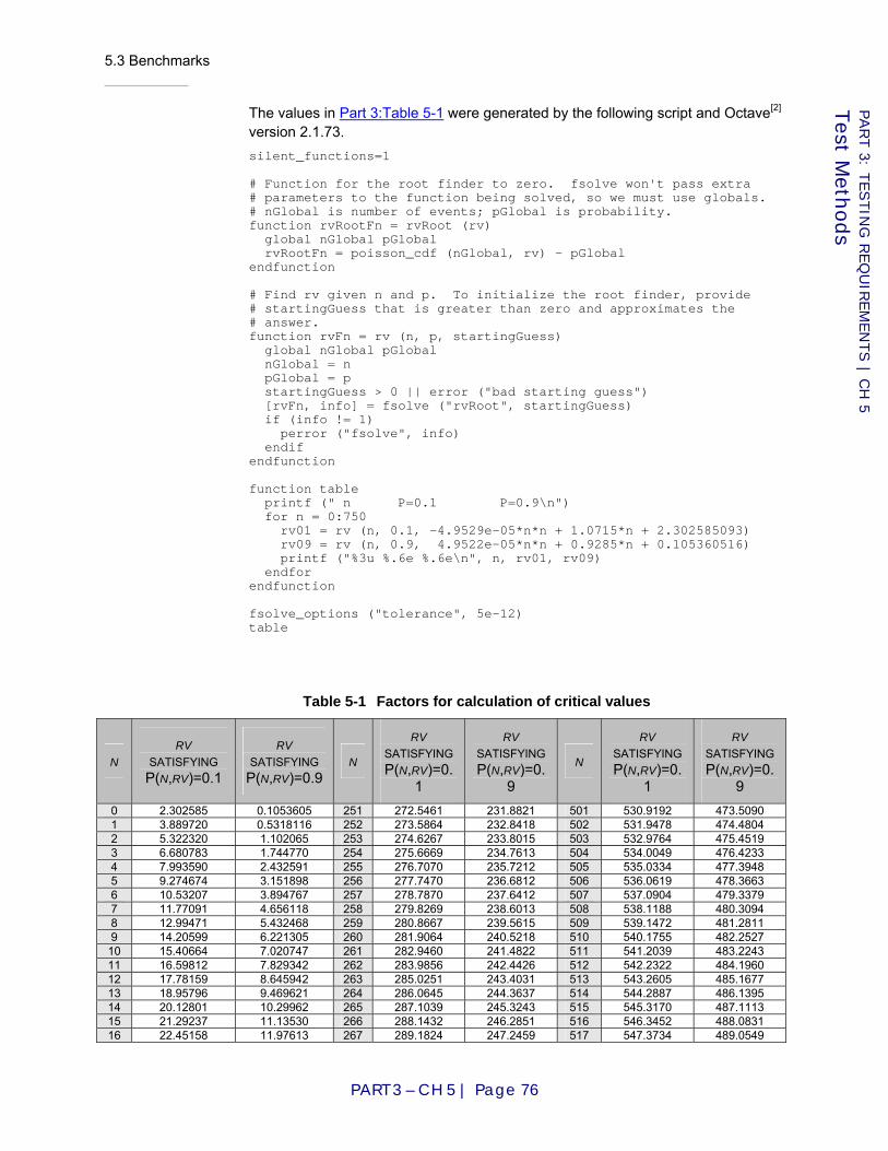
5.3 Benchmarks
PART 3 – CH 5 | Page 76
PART 3: T
ESTIN
G R
EQ
UIR
EM
EN
TS | C
H 5
Test M
ethods
The values in Part 3:Table 5-1 were generated by the following script and Octave[2] version 2.1.73. silent_functions=1 # Function for the root finder to zero. fsolve won't pass extra # parameters to the function being solved, so we must use globals. # nGlobal is number of events; pGlobal is probability. function rvRootFn = rvRoot (rv) global nGlobal pGlobal rvRootFn = poisson_cdf (nGlobal, rv) - pGlobal endfunction # Find rv given n and p. To initialize the root finder, provide # startingGuess that is greater than zero and approximates the # answer. function rvFn = rv (n, p, startingGuess) global nGlobal pGlobal nGlobal = n pGlobal = p startingGuess > 0 || error ("bad starting guess") [rvFn, info] = fsolve ("rvRoot", startingGuess) if (info != 1) perror ("fsolve", info) endif endfunction function table printf (" n P=0.1 P=0.9\n") for n = 0:750 rv01 = rv (n, 0.1, -4.9529e-05*n*n + 1.0715*n + 2.302585093) rv09 = rv (n, 0.9, 4.9522e-05*n*n + 0.9285*n + 0.105360516) printf ("%3u %.6e %.6e\n", n, rv01, rv09) endfor endfunction fsolve_options ("tolerance", 5e-12) table
Table 5-1 Factors for calculation of critical values
N RV
SATISFYING P(N,RV)=0.1
RV SATISFYING P(N,RV)=0.9
N
RV SATISFYING P(N,RV)=0.
1
RV SATISFYING P(N,RV)=0.
9
N
RV SATISFYING P(N,RV)=0.
1
RV SATISFYING P(N,RV)=0.
9 0 2.302585 0.1053605 251 272.5461 231.8821 501 530.9192 473.5090 1 3.889720 0.5318116 252 273.5864 232.8418 502 531.9478 474.4804 2 5.322320 1.102065 253 274.6267 233.8015 503 532.9764 475.4519 3 6.680783 1.744770 254 275.6669 234.7613 504 534.0049 476.4233 4 7.993590 2.432591 255 276.7070 235.7212 505 535.0334 477.3948 5 9.274674 3.151898 256 277.7470 236.6812 506 536.0619 478.3663 6 10.53207 3.894767 257 278.7870 237.6412 507 537.0904 479.3379 7 11.77091 4.656118 258 279.8269 238.6013 508 538.1188 480.3094 8 12.99471 5.432468 259 280.8667 239.5615 509 539.1472 481.2811 9 14.20599 6.221305 260 281.9064 240.5218 510 540.1755 482.2527 10 15.40664 7.020747 261 282.9460 241.4822 511 541.2039 483.2243 11 16.59812 7.829342 262 283.9856 242.4426 512 542.2322 484.1960 12 17.78159 8.645942 263 285.0251 243.4031 513 543.2605 485.1677 13 18.95796 9.469621 264 286.0645 244.3637 514 544.2887 486.1395 14 20.12801 10.29962 265 287.1039 245.3243 515 545.3170 487.1113 15 21.29237 11.13530 266 288.1432 246.2851 516 546.3452 488.0831 16 22.45158 11.97613 267 289.1824 247.2459 517 547.3734 489.0549

5.3 Benchmarks
PART 3 – CH 5 | Page 77
PART 3: T
ESTIN
G R
EQ
UIR
EM
EN
TS | C
H 5
Test M
ethods
N RV
SATISFYING P(N,RV)=0.1
RV SATISFYING P(N,RV)=0.9
N
RV SATISFYING P(N,RV)=0.
1
RV SATISFYING P(N,RV)=0.
9
N
RV SATISFYING P(N,RV)=0.
1
RV SATISFYING P(N,RV)=0.
9 17 23.60609 12.82165 268 290.2215 248.2067 518 548.4015 490.0267 18 24.75629 13.67148 269 291.2605 249.1677 519 549.4296 490.9986 19 25.90253 14.52526 270 292.2995 250.1287 520 550.4577 491.9705 20 27.04510 15.38271 271 293.3384 251.0898 521 551.4858 492.9424 21 28.18427 16.24356 272 294.3773 252.0509 522 552.5138 493.9144 22 29.32027 17.10758 273 295.4160 253.0122 523 553.5418 494.8864 23 30.45330 17.97457 274 296.4547 253.9735 524 554.5698 495.8584 24 31.58356 18.84432 275 297.4934 254.9349 525 555.5978 496.8304 25 32.71121 19.71669 276 298.5319 255.8963 526 556.6257 497.8025 26 33.83639 20.59152 277 299.5704 256.8578 527 557.6536 498.7746 27 34.95926 21.46867 278 300.6088 257.8194 528 558.6815 499.7467 28 36.07992 22.34801 279 301.6472 258.7810 529 559.7094 500.7189 29 37.19850 23.22944 280 302.6855 259.7428 530 560.7372 501.6910 30 38.31510 24.11285 281 303.7237 260.7046 531 561.7650 502.6632 31 39.42982 24.99815 282 304.7618 261.6664 532 562.7928 503.6355 32 40.54274 25.88523 283 305.7999 262.6283 533 563.8205 504.6077 33 41.65395 26.77403 284 306.8379 263.5903 534 564.8482 505.5800 34 42.76352 27.66447 285 307.8758 264.5524 535 565.8759 506.5523 35 43.87152 28.55647 286 308.9137 265.5145 536 566.9036 507.5246 36 44.97802 29.44998 287 309.9515 266.4767 537 567.9313 508.4970 37 46.08308 30.34493 288 310.9893 267.4390 538 568.9589 509.4694 38 47.18676 31.24126 289 312.0269 268.4013 539 569.9865 510.4418 39 48.28910 32.13892 290 313.0646 269.3637 540 571.0140 511.4142 40 49.39016 33.03786 291 314.1021 270.3261 541 572.0416 512.3866 41 50.48999 33.93804 292 315.1396 271.2886 542 573.0691 513.3591 42 51.58863 34.83941 293 316.1770 272.2512 543 574.0966 514.3316 43 52.68612 35.74192 294 317.2144 273.2138 544 575.1241 515.3042 44 53.78250 36.64555 295 318.2517 274.1765 545 576.1515 516.2767 45 54.87781 37.55024 296 319.2889 275.1393 546 577.1789 517.2493 46 55.97209 38.45597 297 320.3261 276.1021 547 578.2063 518.2219 47 57.06535 39.36271 298 321.3632 277.0650 548 579.2337 519.1945 48 58.15765 40.27042 299 322.4002 278.0280 549 580.2610 520.1672 49 59.24900 41.17907 300 323.4372 278.9910 550 581.2884 521.1399 50 60.33944 42.08863 301 324.4741 279.9541 551 582.3156 522.1126 51 61.42899 42.99909 302 325.5110 280.9172 552 583.3429 523.0853 52 62.51768 43.91040 303 326.5478 281.8804 553 584.3702 524.0581 53 63.60553 44.82255 304 327.5845 282.8437 554 585.3974 525.0309 54 64.69257 45.73552 305 328.6212 283.8070 555 586.4246 526.0037 55 65.77881 46.64928 306 329.6578 284.7704 556 587.4517 526.9765 56 66.86429 47.56380 307 330.6944 285.7338 557 588.4789 527.9493 57 67.94901 48.47908 308 331.7309 286.6973 558 589.5060 528.9222 58 69.03300 49.39509 309 332.7673 287.6609 559 590.5331 529.8951 59 70.11628 50.31182 310 333.8037 288.6245 560 591.5602 530.8681 60 71.19887 51.22923 311 334.8400 289.5882 561 592.5872 531.8410 61 72.28078 52.14733 312 335.8763 290.5519 562 593.6142 532.8140 62 73.36203 53.06608 313 336.9125 291.5157 563 594.6412 533.7870 63 74.44263 53.98548 314 337.9486 292.4796 564 595.6682 534.7600 64 75.52260 54.90551 315 338.9847 293.4435 565 596.6952 535.7331 65 76.60196 55.82616 316 340.0208 294.4074 566 597.7221 536.7061 66 77.68071 56.74741 317 341.0568 295.3715 567 598.7490 537.6792 67 78.75888 57.66924 318 342.0927 296.3355 568 599.7759 538.6523 68 79.83647 58.59165 319 343.1285 297.2997 569 600.8028 539.6255 69 80.91350 59.51463 320 344.1643 298.2639 570 601.8296 540.5986 70 81.98997 60.43815 321 345.2001 299.2281 571 602.8564 541.5718 71 83.06591 61.36221 322 346.2358 300.1924 572 603.8832 542.5450 72 84.14132 62.28680 323 347.2714 301.1568 573 604.9099 543.5183 73 85.21622 63.21191 324 348.3070 302.1212 574 605.9367 544.4915 74 86.29061 64.13753 325 349.3426 303.0857 575 606.9634 545.4648 75 87.36450 65.06364 326 350.3780 304.0502 576 607.9901 546.4381 76 88.43790 65.99023 327 351.4135 305.0148 577 609.0168 547.4115

5.3 Benchmarks
PART 3 – CH 5 | Page 78
PART 3: T
ESTIN
G R
EQ
UIR
EM
EN
TS | C
H 5
Test M
ethods
N RV
SATISFYING P(N,RV)=0.1
RV SATISFYING P(N,RV)=0.9
N
RV SATISFYING P(N,RV)=0.
1
RV SATISFYING P(N,RV)=0.
9
N
RV SATISFYING P(N,RV)=0.
1
RV SATISFYING P(N,RV)=0.
9 77 89.51083 66.91731 328 352.4488 305.9794 578 610.0434 548.3848 78 90.58329 67.84485 329 353.4842 306.9441 579 611.0700 549.3582 79 91.65529 68.77285 330 354.5194 307.9088 580 612.0966 550.3316 80 92.72684 69.70130 331 355.5546 308.8736 581 613.1232 551.3050 81 93.79795 70.63019 332 356.5898 309.8384 582 614.1498 552.2785 82 94.86863 71.55951 333 357.6249 310.8033 583 615.1763 553.2519 83 95.93888 72.48927 334 358.6599 311.7683 584 616.2028 554.2254 84 97.00871 73.41944 335 359.6949 312.7333 585 617.2293 555.1989 85 98.07813 74.35002 336 360.7299 313.6983 586 618.2558 556.1725 86 99.14714 75.28100 337 361.7648 314.6634 587 619.2822 557.1460 87 100.2158 76.21239 338 362.7996 315.6286 588 620.3086 558.1196 88 101.2840 77.14416 339 363.8344 316.5938 589 621.3350 559.0932 89 102.3518 78.07631 340 364.8692 317.5591 590 622.3614 560.0668 90 103.4193 79.00885 341 365.9038 318.5244 591 623.3878 561.0405 91 104.4864 79.94175 342 366.9385 319.4897 592 624.4141 562.0141 92 105.5531 80.87502 343 367.9731 320.4552 593 625.4404 562.9878 93 106.6195 81.80865 344 369.0076 321.4206 594 626.4667 563.9615 94 107.6855 82.74263 345 370.0421 322.3861 595 627.4930 564.9353 95 108.7512 83.67695 346 371.0765 323.3517 596 628.5192 565.9090 96 109.8165 84.61162 347 372.1109 324.3173 597 629.5454 566.8828 97 110.8815 85.54663 348 373.1453 325.2830 598 630.5716 567.8566 98 111.9462 86.48197 349 374.1796 326.2487 599 631.5978 568.8304 99 113.0105 87.41764 350 375.2138 327.2144 600 632.6240 569.8043 100 114.0745 88.35362 351 376.2480 328.1802 601 633.6501 570.7781 101 115.1382 89.28993 352 377.2821 329.1461 602 634.6762 571.7520 102 116.2016 90.22655 353 378.3162 330.1120 603 635.7023 572.7259 103 117.2647 91.16347 354 379.3503 331.0780 604 636.7284 573.6999 104 118.3275 92.10070 355 380.3843 332.0440 605 637.7544 574.6738 105 119.3899 93.03823 356 381.4182 333.0100 606 638.7804 575.6478 106 120.4521 93.97605 357 382.4521 333.9761 607 639.8064 576.6218 107 121.5140 94.91416 358 383.4860 334.9422 608 640.8324 577.5958 108 122.5756 95.85256 359 384.5198 335.9084 609 641.8584 578.5699 109 123.6369 96.79124 360 385.5536 336.8747 610 642.8843 579.5439 110 124.6980 97.73020 361 386.5873 337.8410 611 643.9102 580.5180 111 125.7587 98.66944 362 387.6209 338.8073 612 644.9361 581.4921 112 126.8192 99.60895 363 388.6546 339.7737 613 645.9620 582.4662 113 127.8794 100.5487 364 389.6881 340.7401 614 646.9879 583.4404 114 128.9394 101.4888 365 390.7217 341.7066 615 648.0137 584.4145 115 129.9991 102.4291 366 391.7552 342.6731 616 649.0395 585.3887 116 131.0586 103.3696 367 392.7886 343.6396 617 650.0653 586.3629 117 132.1177 104.3104 368 393.8220 344.6062 618 651.0911 587.3372 118 133.1767 105.2515 369 394.8553 345.5729 619 652.1168 588.3114 119 134.2354 106.1928 370 395.8886 346.5396 620 653.1426 589.2857 120 135.2938 107.1344 371 396.9219 347.5063 621 654.1683 590.2600 121 136.3520 108.0762 372 397.9551 348.4731 622 655.1940 591.2343 122 137.4100 109.0182 373 398.9883 349.4399 623 656.2196 592.2086 123 138.4677 109.9605 374 400.0214 350.4068 624 657.2453 593.1830 124 139.5252 110.9030 375 401.0545 351.3737 625 658.2709 594.1573 125 140.5825 111.8457 376 402.0875 352.3407 626 659.2965 595.1317 126 141.6395 112.7887 377 403.1205 353.3077 627 660.3221 596.1061 127 142.6963 113.7318 378 404.1535 354.2748 628 661.3477 597.0806 128 143.7529 114.6753 379 405.1864 355.2419 629 662.3732 598.0550 129 144.8093 115.6189 380 406.2192 356.2090 630 663.3987 599.0295 130 145.8655 116.5627 381 407.2520 357.1762 631 664.4242 600.0040 131 146.9214 117.5068 382 408.2848 358.1434 632 665.4497 600.9785 132 147.9771 118.4511 383 409.3176 359.1107 633 666.4752 601.9530 133 149.0326 119.3955 384 410.3503 360.0780 634 667.5006 602.9276 134 150.0880 120.3402 385 411.3829 361.0453 635 668.5261 603.9022 135 151.1431 121.2851 386 412.4155 362.0127 636 669.5515 604.8768 136 152.1980 122.2302 387 413.4481 362.9802 637 670.5768 605.8514

5.3 Benchmarks
PART 3 – CH 5 | Page 79
PART 3: T
ESTIN
G R
EQ
UIR
EM
EN
TS | C
H 5
Test M
ethods
N RV
SATISFYING P(N,RV)=0.1
RV SATISFYING P(N,RV)=0.9
N
RV SATISFYING P(N,RV)=0.
1
RV SATISFYING P(N,RV)=0.
9
N
RV SATISFYING P(N,RV)=0.
1
RV SATISFYING P(N,RV)=0.
9 137 153.2527 123.1755 388 414.4806 363.9476 638 671.6022 606.8260 138 154.3072 124.1210 389 415.5131 364.9152 639 672.6276 607.8007 139 155.3615 125.0667 390 416.5455 365.8827 640 673.6529 608.7754 140 156.4156 126.0126 391 417.5779 366.8503 641 674.6782 609.7501 141 157.4695 126.9586 392 418.6103 367.8180 642 675.7035 610.7248 142 158.5233 127.9049 393 419.6426 368.7856 643 676.7287 611.6995 143 159.5768 128.8514 394 420.6749 369.7534 644 677.7540 612.6743 144 160.6302 129.7980 395 421.7071 370.7211 645 678.7792 613.6490 145 161.6834 130.7448 396 422.7393 371.6890 646 679.8044 614.6238 146 162.7364 131.6918 397 423.7714 372.6568 647 680.8296 615.5986 147 163.7892 132.6390 398 424.8035 373.6247 648 681.8548 616.5735 148 164.8418 133.5864 399 425.8356 374.5926 649 682.8799 617.5483 149 165.8943 134.5339 400 426.8676 375.5606 650 683.9050 618.5232 150 166.9465 135.4816 401 427.8996 376.5286 651 684.9302 619.4981 151 167.9987 136.4295 402 428.9316 377.4966 652 685.9552 620.4730 152 169.0506 137.3776 403 429.9635 378.4647 653 686.9803 621.4479 153 170.1024 138.3258 404 430.9954 379.4329 654 688.0054 622.4229 154 171.1540 139.2742 405 432.0272 380.4010 655 689.0304 623.3978 155 172.2054 140.2228 406 433.0590 381.3692 656 690.0554 624.3728 156 173.2567 141.1715 407 434.0907 382.3375 657 691.0804 625.3478 157 174.3078 142.1204 408 435.1225 383.3058 658 692.1054 626.3228 158 175.3587 143.0695 409 436.1541 384.2741 659 693.1304 627.2979 159 176.4095 144.0187 410 437.1858 385.2425 660 694.1553 628.2729 160 177.4601 144.9681 411 438.2174 386.2109 661 695.1802 629.2480 161 178.5106 145.9176 412 439.2489 387.1793 662 696.2051 630.2231 162 179.5609 146.8673 413 440.2805 388.1478 663 697.2300 631.1982 163 180.6111 147.8171 414 441.3119 389.1163 664 698.2549 632.1734 164 181.6611 148.7671 415 442.3434 390.0848 665 699.2797 633.1485 165 182.7109 149.7173 416 443.3748 391.0534 666 700.3045 634.1237 166 183.7606 150.6676 417 444.4062 392.0221 667 701.3293 635.0989 167 184.8102 151.6180 418 445.4375 392.9907 668 702.3541 636.0741 168 185.8596 152.5686 419 446.4688 393.9594 669 703.3789 637.0493 169 186.9089 153.5193 420 447.5001 394.9282 670 704.4036 638.0246 170 187.9580 154.4702 421 448.5313 395.8969 671 705.4284 638.9999 171 189.0069 155.4213 422 449.5625 396.8658 672 706.4531 639.9751 172 190.0558 156.3724 423 450.5936 397.8346 673 707.4778 640.9505 173 191.1045 157.3237 424 451.6247 398.8035 674 708.5025 641.9258 174 192.1530 158.2752 425 452.6558 399.7724 675 709.5271 642.9011 175 193.2014 159.2268 426 453.6868 400.7414 676 710.5518 643.8765 176 194.2497 160.1785 427 454.7178 401.7104 677 711.5764 644.8518 177 195.2978 161.1304 428 455.7488 402.6794 678 712.6010 645.8272 178 196.3458 162.0824 429 456.7797 403.6485 679 713.6256 646.8027 179 197.3937 163.0345 430 457.8106 404.6176 680 714.6501 647.7781 180 198.4414 163.9868 431 458.8415 405.5867 681 715.6747 648.7535 181 199.4890 164.9392 432 459.8723 406.5559 682 716.6992 649.7290 182 200.5365 165.8917 433 460.9031 407.5251 683 717.7237 650.7045 183 201.5839 166.8443 434 461.9338 408.4944 684 718.7482 651.6800 184 202.6311 167.7971 435 462.9646 409.4637 685 719.7727 652.6555 185 203.6781 168.7501 436 463.9952 410.4330 686 720.7972 653.6311 186 204.7251 169.7031 437 465.0259 411.4023 687 721.8216 654.6066 187 205.7719 170.6563 438 466.0565 412.3717 688 722.8461 655.5822 188 206.8186 171.6096 439 467.0871 413.3412 689 723.8705 656.5578 189 207.8652 172.5630 440 468.1176 414.3106 690 724.8949 657.5334 190 208.9117 173.5165 441 469.1481 415.2801 691 725.9192 658.5090 191 209.9580 174.4702 442 470.1786 416.2496 692 726.9436 659.4847 192 211.0043 175.4239 443 471.2090 417.2192 693 727.9679 660.4603 193 212.0504 176.3778 444 472.2394 418.1888 694 728.9922 661.4360 194 213.0963 177.3319 445 473.2698 419.1584 695 730.0165 662.4117 195 214.1422 178.2860 446 474.3001 420.1281 696 731.0408 663.3874 196 215.1879 179.2403 447 475.3304 421.0978 697 732.0651 664.3631
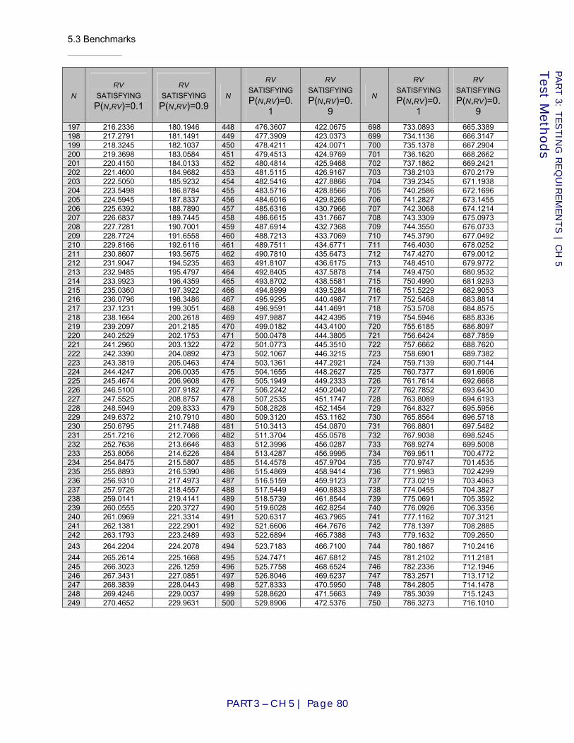
5.3 Benchmarks
PART 3 – CH 5 | Page 80
PART 3: T
ESTIN
G R
EQ
UIR
EM
EN
TS | C
H 5
Test M
ethods
N RV
SATISFYING P(N,RV)=0.1
RV SATISFYING P(N,RV)=0.9
N
RV SATISFYING P(N,RV)=0.
1
RV SATISFYING P(N,RV)=0.
9
N
RV SATISFYING P(N,RV)=0.
1
RV SATISFYING P(N,RV)=0.
9 197 216.2336 180.1946 448 476.3607 422.0675 698 733.0893 665.3389 198 217.2791 181.1491 449 477.3909 423.0373 699 734.1136 666.3147 199 218.3245 182.1037 450 478.4211 424.0071 700 735.1378 667.2904 200 219.3698 183.0584 451 479.4513 424.9769 701 736.1620 668.2662 201 220.4150 184.0133 452 480.4814 425.9468 702 737.1862 669.2421 202 221.4600 184.9682 453 481.5115 426.9167 703 738.2103 670.2179 203 222.5050 185.9232 454 482.5416 427.8866 704 739.2345 671.1938 204 223.5498 186.8784 455 483.5716 428.8566 705 740.2586 672.1696 205 224.5945 187.8337 456 484.6016 429.8266 706 741.2827 673.1455 206 225.6392 188.7890 457 485.6316 430.7966 707 742.3068 674.1214 207 226.6837 189.7445 458 486.6615 431.7667 708 743.3309 675.0973 208 227.7281 190.7001 459 487.6914 432.7368 709 744.3550 676.0733 209 228.7724 191.6558 460 488.7213 433.7069 710 745.3790 677.0492 210 229.8166 192.6116 461 489.7511 434.6771 711 746.4030 678.0252 211 230.8607 193.5675 462 490.7810 435.6473 712 747.4270 679.0012 212 231.9047 194.5235 463 491.8107 436.6175 713 748.4510 679.9772 213 232.9485 195.4797 464 492.8405 437.5878 714 749.4750 680.9532 214 233.9923 196.4359 465 493.8702 438.5581 715 750.4990 681.9293 215 235.0360 197.3922 466 494.8999 439.5284 716 751.5229 682.9053 216 236.0796 198.3486 467 495.9295 440.4987 717 752.5468 683.8814 217 237.1231 199.3051 468 496.9591 441.4691 718 753.5708 684.8575 218 238.1664 200.2618 469 497.9887 442.4395 719 754.5946 685.8336 219 239.2097 201.2185 470 499.0182 443.4100 720 755.6185 686.8097 220 240.2529 202.1753 471 500.0478 444.3805 721 756.6424 687.7859 221 241.2960 203.1322 472 501.0773 445.3510 722 757.6662 688.7620 222 242.3390 204.0892 473 502.1067 446.3215 723 758.6901 689.7382 223 243.3819 205.0463 474 503.1361 447.2921 724 759.7139 690.7144 224 244.4247 206.0035 475 504.1655 448.2627 725 760.7377 691.6906 225 245.4674 206.9608 476 505.1949 449.2333 726 761.7614 692.6668 226 246.5100 207.9182 477 506.2242 450.2040 727 762.7852 693.6430 227 247.5525 208.8757 478 507.2535 451.1747 728 763.8089 694.6193 228 248.5949 209.8333 479 508.2828 452.1454 729 764.8327 695.5956 229 249.6372 210.7910 480 509.3120 453.1162 730 765.8564 696.5718 230 250.6795 211.7488 481 510.3413 454.0870 731 766.8801 697.5482 231 251.7216 212.7066 482 511.3704 455.0578 732 767.9038 698.5245 232 252.7636 213.6646 483 512.3996 456.0287 733 768.9274 699.5008 233 253.8056 214.6226 484 513.4287 456.9995 734 769.9511 700.4772 234 254.8475 215.5807 485 514.4578 457.9704 735 770.9747 701.4535 235 255.8893 216.5390 486 515.4869 458.9414 736 771.9983 702.4299 236 256.9310 217.4973 487 516.5159 459.9123 737 773.0219 703.4063 237 257.9726 218.4557 488 517.5449 460.8833 738 774.0455 704.3827 238 259.0141 219.4141 489 518.5739 461.8544 739 775.0691 705.3592 239 260.0555 220.3727 490 519.6028 462.8254 740 776.0926 706.3356 240 261.0969 221.3314 491 520.6317 463.7965 741 777.1162 707.3121 241 262.1381 222.2901 492 521.6606 464.7676 742 778.1397 708.2885 242 263.1793 223.2489 493 522.6894 465.7388 743 779.1632 709.2650 243 264.2204 224.2078 494 523.7183 466.7100 744 780.1867 710.2416 244 265.2614 225.1668 495 524.7471 467.6812 745 781.2102 711.2181 245 266.3023 226.1259 496 525.7758 468.6524 746 782.2336 712.1946 246 267.3431 227.0851 497 526.8046 469.6237 747 783.2571 713.1712 247 268.3839 228.0443 498 527.8333 470.5950 748 784.2805 714.1478 248 269.4246 229.0037 499 528.8620 471.5663 749 785.3039 715.1243 249 270.4652 229.9631 500 529.8906 472.5376 750 786.3273 716.1010

5.3 Benchmarks
PART 3 – CH 5 | Page 81
PART 3: T
ESTIN
G R
EQ
UIR
EM
EN
TS | C
H 5
Test M
ethods
Table 5-2 Plot of values from Table 5-1
5.3.3 Reliability
5.3.3-A Reliability, pertinent tests
All tests executed during conformity assessment SHALL be considered "pertinent" for assessment of reliability, with the following exceptions:
a. Tests in which failures are forced; b. Tests in which portions of the system that would be exercised during
an actual election are bypassed (see Part 3:2.5.3 “Test fixtures”). Applies to: Voting system
0
5
10
15
20
25
30
0 5 10 15 20
rv
Number of events (n)
P(n,rv)=0.1P(n,rv)=0.9
5.3 Benchmarks
PART 3 – CH 5 | Page 82
PART 3: T
ESTIN
G R
EQ
UIR
EM
EN
TS | C
H 5
Test M
ethods
5.3.3-B Failure rate data collection
The test lab SHALL record the number of failures and the applicable measure of volume for each pertinent test execution, for each type of device, and for each applicable failure type in Part 1:Table 6-3 (Part 1:6.3.1.5 “Requirements”).
Applies to: Voting device
D I S C U S S I O N
"Type of device" refers to the different models produced by the manufacturer. These are not the same as device classes. The system may include several different models of the same class, and a given model may belong to more than one class.
5.3.3-C Failure rate pass criteria
When operational testing is complete, the test lab SHALL calculate the failure total and total volume accumulated across all pertinent tests for each type of device and failure type. If, using the test method in Part 3:5.3.1 “General method”, these values indicate rejection of the null hypothesis for any type of device and type of failure, the verdict on conformity to Requirement Part 1:6.3.1.5-A SHALL be Fail. Otherwise, the verdict SHALL be Pass.
Applies to: Voting device
5.3.4 Accuracy
The informal concept of voting system accuracy is formalized using the ratio of the number of errors that occur to the volume of data processed, also known as error rate.
5.3.4-A Accuracy, pertinent tests
All tests executed during conformity assessment SHALL be considered "pertinent" for assessment of accuracy, with the following exceptions:
a. Tests in which errors are forced; b. Tests in which portions of the system that would be exercised during
an actual election are bypassed (see Part 3:2.5.3 “Test fixtures”). Applies to: Voting system
5.3.4-B Calculation of report total error rate
Given a set of vote data reports resulting from the execution of tests, the observed cumulative report total error rate SHALL be calculated as follows:
a. Define a "report item" as any one of the numeric values (totals or counts) that must appear in any of the vote data reports. Each ballot count, each vote, overvote, and undervote total for each contest, and each vote total for each contest choice in each contest is a separate

5.3 Benchmarks
PART 3 – CH 5 | Page 83
PART 3: T
ESTIN
G R
EQ
UIR
EM
EN
TS | C
H 5
Test M
ethods
report item. The required report items are detailed in Part 1:7.8.3 “Vote data reports”;
b. For each report item, compute the "report item error" as the absolute value of the difference between the correct value and the reported value. Special cases: If a value is reported that should not have appeared at all (spurious item), or if an item that should have appeared in the report does not (missing item), assess a report item error of one. Additional values that are reported as a manufacturer extension to the standard are not considered spurious items;
c. Compute the "report total error" as the sum of all of the report item errors from all of the reports;
d. Compute the "report total volume" as the sum of all of the correct values for all of the report items that are supposed to appear in the reports. Special cases: When the same logical contest appears multiple times (e.g., when results are reported for each ballot configuration and then combined or when reports are generated for multiple reporting contexts), each manifestation of the logical contest is considered a separate contest with its own correct vote totals in this computation;
e. Compute the observed cumulative report total error rate as the ratio of the report total error to the report total volume. Special cases: If both values are zero, the report total error rate is zero. If the report total volume is zero but the report total error is not, the report total error rate is infinite;
Applies to: Voting system
Source: Revision of [GPO90] F.6
5.3.4-C Error rate data collection
The test lab SHALL record the report total error and report total volume for each pertinent test execution.
Applies to: Voting system
D I S C U S S I O N
Accuracy is calculated as a system-level metric, not separated by device type.
5.3.4-D Error rate pass criteria
When operational testing is complete, the test lab SHALL calculate the report total error and report total volume accumulated across all pertinent tests. If, using the test method in Part 3:5.3.1 “General method”, these values indicate rejection of the null hypothesis, the verdict on conformity to Requirement Part 1:6.3.2-B SHALL be Fail. Otherwise, the verdict SHALL be Pass.
Applies to: Voting system
5.3.5 Misfeed rate
This benchmark applies only to paper-based tabulators and EBMs.
5.3 Benchmarks
PART 3 – CH 5 | Page 84
PART 3: T
ESTIN
G R
EQ
UIR
EM
EN
TS | C
H 5
Test M
ethods
Multiple feeds, misfeeds (jams), and rejections of ballots that meet all manufacturer specifications are all treated collectively as "misfeeds" for benchmarking purposes (i.e., only a single count is maintained).
5.3.5-A Misfeed rate, pertinent tests
All tests executed during conformity assessment SHALL be considered "pertinent" for assessment of misfeed rate, with the following exceptions:
a. Tests in which misfeeds are forced. Applies to: Voting system
5.3.5-B Calculation of misfeed rate
For paper-based tabulators and EBMs, the observed cumulative misfeed rate SHALL be calculated as follows:
a. Compute the "misfeed total" as the number of times that unforced multiple feed, misfeed (jam), or rejection of a ballot that meets all manufacturer specifications has occurred during the execution of tests. It is possible for a given ballot to misfeed more than once – in such a case, each misfeed would be counted:
b. Compute the "total ballot volume" as the number of successful feeds of ballot pages or cards during the execution of tests. (If the pages of a multi-page ballot are fed separately, each page counts; but if both sides of a two-sided ballot are read in one pass through the tabulator, it only counts once);
c. Compute the observed cumulative misfeed rate as the ratio of the misfeed total to the total ballot volume. Special cases: If both values are zero, the misfeed rate is zero. If the total ballot volume is zero but the misfeed total is not, the misfeed rate is infinite.
Applies to: Paper-based device ⋀ Tabulator, EBM
D I S C U S S I O N
"During the execution of tests" deliberately excludes jams that occur during pre-testing setup and calibration of the equipment. Uncalibrated equipment can be expected to jam frequently.
Source: New requirement
5.3.5-C Misfeed rate data collection
The test lab SHALL record the misfeed total and total ballot volume for each pertinent test execution, for each type of device.
Applies to: Paper-based device ⋀ Tabulator, EBM
D I S C U S S I O N
"Type of device" refers to the different models of paper-based tabulators and EBMs produced by the manufacturer.
5.4 Open-Ended Vulnerability Testing
PART 3 – CH 5 | Page 85
PART 3: T
ESTIN
G R
EQ
UIR
EM
EN
TS | C
H 5
Test M
ethods
5.3.5-D Misfeed rate pass criteria
When operational testing is complete, the test lab SHALL calculate the misfeed total and total ballot volume accumulated across all pertinent tests. If, using the test method in Part 3:5.3.1 “General method”, these values indicate rejection of the null hypothesis for any type of device, the verdict on conformity to Requirement Part 1:6.3.3-A SHALL be Fail. Otherwise, the verdict SHALL be Pass.
Applies to: Paper-based device ⋀ Tabulator, EBM
5.4 Open-Ended Vulnerability Testing
Vulnerability testing is an attempt to bypass or break the security of a system or a device. Like functional testing, vulnerability testing can falsify a general assertion (namely, demonstrate that the system or device is secure) but it cannot verify the security (show that the system or device is secure in all cases). Open-ended vulnerability testing (OEVT) is conducted without the confines of a pre-determined test suite. It instead relies heavily on the experience and expertise of the OEVT Team Members, their knowledge of the system, its component devices and associated vulnerabilities, and their ability to exploit those vulnerabilities.
The goal of OEVT is to discover architecture, design and implementation flaws in the system that may not be detected using systematic functional, reliability, and security testing and which may be exploited to change the outcome of an election, interfere with voters’ ability to cast ballots or have their votes counted during an election or compromise the secrecy of the vote. The goal of OEVT also includes attempts to discover logic bombs, time bombs or other Trojan Horses that may have been introduced into the system hardware, firmware, or software for said purposes.
5.4.1 OEVT scope and priorities
5.4.1-A Scope of open-ended vulnerability testing
The scope of open ended vulnerability testing SHALL include the voting system security during all phases of the voting process and SHALL include all manufacturer supplied voting system use procedures. D I S C U S S I O N
The scope of OEVT includes but is not limited to the following:
1. Voting system security;
2. Voting system physical security while voting devices are:
A. In storage;
B. Being configured;
C. Being transported; and

5.4 Open-Ended Vulnerability Testing
PART 3 – CH 5 | Page 86
PART 3: T
ESTIN
G R
EQ
UIR
EM
EN
TS | C
H 5
Test M
ethods
D. Being used.
3. Voting system use procedures. Source: New requirement
5.4.1-B Focus of open-ended vulnerability testing
OEVT Team members SHALL seek out vulnerabilities in the voting system that might be used to change the outcome of an election, to interfere with voters’ ability to cast ballots or have their votes counted during an election or to compromise the secrecy of vote. Source: New requirement
5.4.1-C OEVT General Priorities
The OEVT team SHALL prioritize testing efforts based on: a. threat scenarios for the voting system under investigation; b. the availability of time and resources; c. the OEVT team’s determination of easily exploitable vulnerabilities;
and d. the OEVT team’s determination of which exploitation scenarios are
more likely to impact the outcome of an election, interfere with voters’ ability to cast ballots or have their votes counted during an election or compromise the secrecy of the vote.
D I S C U S S I O N
Following are suggestions for OEVT prioritization in the areas of threat scenarios, COTS products and Internet based threats. The intent here is to provide guidance on how to prioritize testing efforts given specific voting device implementations.
1. All threat scenarios must be plausible in that they should not be in conflict with the anticipated implementation, associated use procedures, the workmanship requirements in section 6.4 (assuming those requirements were all met) or the development environment specification as supplied by the manufacturer in the TDP;
2. Open-ended vulnerability testing should not exclude those threat scenarios involving collusion between multiple parties including manufacturer insiders. It is acknowledged that threat scenarios become less plausible as the number of conspirators increases;
3. It is assumed that attackers may be well resourced and may have access to the system while under development;
4. Threats that can be exploited to change the outcome of an election and flaws that can provide erroneous results for an election should have the highest priority;
5. Threats that can cause a denial of service during the election should be considered of very high priority;
6. Threats that can compromise the secrecy of the vote should be considered of high priority;
7. A threat to disclosure or modification of metadata (e.g., security audit log) that does not change the outcome of the election, does not

5.4 Open-Ended Vulnerability Testing
PART 3 – CH 5 | Page 87
PART 3: T
ESTIN
G R
EQ
UIR
EM
EN
TS | C
H 5
Test M
ethods
cause denial of service during the election, or does not compromise the secrecy of ballot should be considered of lower priority;
8. If the voting device uses COTS products, then the OEVT team should also investigate publicly known vulnerabilities; and
9. The OEVT team should not consider the voting device vulnerabilities that require Internet connectivity for exploitation if the voting device is not connected to the Internet during the election and otherwise. However, if the voting device is connected to another device which in turn may have been connected to the Internet (as may be the case of epollbooks), Internet based attacks may be plausible and should be investigated.
Source: New requirement
5.4.2 OEVT resources and level of effort
5.4.2-A OEVT team resources
The OEVT team SHALL use the manufacturer supplied Technical Data Package (TDP) and User documentation, have access to voting devices configured similar to how they are to be used in an election, and have access to all other material and tools necessary to conduct a thorough investigation. D I S C U S S I O N
Materials supplied to the OEVT team should include but not be limited to the following:
1. Threat analysis describing threats mitigated by the voting system;
2. Security architecture describing how threats to the voting system are mitigated;
3. High level design of the system;
4. Any other documentation provided to the testing laboratory;
5. Source code;
6. Operational voting system configured for election, but with the ability for the OEVT team to reconfigure it;
7. Testing reports from the developer and from the testing laboratory including previous OEVT results;
8. Tools sufficient to conduct a test lab build; and
9. Procedures specified by the manufacturer as necessary for implementation and secure use.
Source: New requirement
5.4.2-B Open-ended vulnerability team establishment
The test lab SHALL establish an OEVT team of at least 3 security experts and at least one election management expert to conduct the open-ended vulnerability testing.

5.4 Open-Ended Vulnerability Testing
PART 3 – CH 5 | Page 88
PART 3: T
ESTIN
G R
EQ
UIR
EM
EN
TS | C
H 5
Test M
ethods
Source: New requirement
5.4.2-C OEVT team composition – security experts
The OEVT team SHALL have at least one member with 6 or more years of experience in the area of software engineering, at least one member with 6 or more years of experience in the area of information security, at least one member with 6 or more years of experience in the area of penetration testing and at least one member with 6 or more years of experience in the area of voting system security. Source: New requirement
5.4.2-D OEVT Team Composition- Election Management Expert
The OEVT team SHALL have at least one member with at least 8 years of experience in the area of election management. D I S C U S S I O N
The OEVT team will require consultation from an elections expert who is familiar with election procedures, how the voting systems are installed and used, and how votes are counted.
Source: New requirement
5.4.2-E OEVT team knowledge
The OEVT team knowledge SHALL include but not be limited to the following:
a. Complete knowledge of work done to date on voting system design, research and analysis conducted on voting system security, and known and suspected flaws in voting systems;
b. Complete knowledge of threats to voting systems; c. Knowledge equivalent to a Bachelor’s degree in computer science or
related field; d. Experience in design, implementation, security analysis, or testing of
technologies or products involved in voting system; and e. Experience in the conduct and management of elections.
Source: New requirement
5.4.2-F OEVT level of effort – test plan
In determining the level of effort to apply to open-ended vulnerability testing, the test lab SHALL take into consideration the size and complexity of the voting system; any available results from the “close ended” functional, security, and usability testing activities and laboratory analysis and testing activities; the number of vulnerabilities found in previous security analyses; and testing of the voting system and its prior versions. Source: New requirement
5.4 Open-Ended Vulnerability Testing
PART 3 – CH 5 | Page 89
PART 3: T
ESTIN
G R
EQ
UIR
EM
EN
TS | C
H 5
Test M
ethods
5.4.2-G OEVT level of effort – commitment of resources
The OEVT team SHALL examine the system for a minimum of 12 staff weeks. Source: New requirement
5.4.3 Rules of engagement
5.4.3-A Rules of engagement – context of testing
Open ended vulnerability testing shall be conducted within the context of a process model describing a specific implementation of the voting system and a corresponding model of plausible threats. D I S C U S S I O N
The specification of these models is supported by information provided by the manufacturer as part of the TDP. See Requirement Part 2:3.5.1.
Source: New requirement
5.4.3-B Rules of engagement – adequate system model
The OEVT team shall verify that the manufacturer provided system model sufficiently describes the intended implementation of the voting system. D I S C U S S I O N
Manufacturer’s system model and associated documentation should reliably describe the voting system and all associated use procedures given the environment in which the system will be used.
Source: New requirement
5.4.3-C Rules of engagement – adequate threat model
The OEVT team shall verify that the threat model sufficiently addresses significant threats to the voting system. D I S C U S S I O N
Significant threats are those that could:
1. Change the outcome of an election;
2. Interfere with voters’ ability to cast ballots or have their votes counted during an election; or
3. Compromise the secrecy of vote.
OEVT team may modify the manufacturer’s threat model to include additional, plausible threats.
Source: New requirement
5.4 Open-Ended Vulnerability Testing
PART 3 – CH 5 | Page 90
PART 3: T
ESTIN
G R
EQ
UIR
EM
EN
TS | C
H 5
Test M
ethods
5.4.4 Fail criteria
5.4.4-A OEVT fail criteria – violation of requirements
The voting device shall fail open ended vulnerability testing if the OEVT team finds vulnerabilities or errors in the voting device that violate requirements in the VVSG. D I S C U S S I O N
While the OEVT is directed at issues of device and system security, a violation of any requirement in the VVSG can lead to failure. Following are examples of issues for which the test lab must give a recommendation of “fail”:
1. Evidence that any single person can cause a violation of a voting system security goal (e.g., integrity of election results, privacy of the voter, availability of the voting system), assuming that all other parties follow procedures appropriate for their roles as specified in the manufacturer’s documentation;
2. Manufacturer's documentation fails to adequately document all aspects of system design, development, and proper usage that are relevant to system security. This includes but is not limited to the following:
A. System security objectives;
B. Initialization, usage, and maintenance procedures necessary to secure operation;
C. All attacks the system is designed to resist or detect; and
D. Any security vulnerabilities known to the manufacturer.
3. Use of a cryptographic module that has not been validated against FIPS 140-2;
4. Ability to modify electronic event logs without detection;
5. A VVPR that has an inaccurate or incomplete summary of the cast electronic vote;
6. Unidentified software on the voting system;
7. Identified software which lacks documentation of the functionality it provides to the voting device;
8. Access to configuration file without authentication;
9. Ability to cast more than one ballot within a voting session;
10. Ability to perform restore operations in Activated State;
11. Enabled remote access in Activated State; and/or
12. Ballot boxes without appropriate tamper evidence countermeasures. Source: New requirement
5.4 Open-Ended Vulnerability Testing
PART 3 – CH 5 | Page 91
PART 3: T
ESTIN
G R
EQ
UIR
EM
EN
TS | C
H 5
Test M
ethods
5.4.4-B Threat model - failure
Voting systems shall fail open ended vulnerability testing if the manufacturer’s model of the system along with associated use procedures and security controls does not adequately mitigate all significant threats as described in the threat model. D I S C U S S I O N
Team may use a threat model that has been amended based on their findings in accordance with 5.4.3-C.
Source: New requirement
5.4.4-C OEVT fail criteria – critical flaws
The voting device shall fail open ended vulnerability testing if the OEVT team provides a plausible description of how vulnerabilities or errors found in a voting device or the implementation of its security features could be used to:
a. Change the outcome of an election; b. Interfere with voters’ ability to cast ballots or have their votes
counted during an election; or c. Compromise the secrecy of vote without having to demonstrate a
successful exploitation of said vulnerabilities or errors. D I S C U S S I O N
The OEVT team does not have to develop an attack and demonstrate the exploitation of the vulnerabilities or errors they find. They do however have to offer a plausible analysis to support their claims.
Source: New requirement
5.4.5 OEVT reporting requirements
5.4.5-A OEVT reporting requirements
The OEVT team SHALL record all information discovered during the open-ended vulnerability test, including but not limited to:
a. Names, organizational affiliations, summary qualifications, and resumes of the members of the OEVT;
b. Time spent by each individual on the OEVT activities; c. List of hypotheses considered; d. List of hypotheses rejected and rationale; e. List of hypotheses tested, testing approach, and testing outcomes;
and f. List and description of remaining vulnerabilities in the voting system:
1. A description of each vulnerability including how the vulnerability can be exploited and the nature of the impact;
2. For each vulnerability, the OEVT team should identify any VVSG requirements violated; and
3. The OEVT team should flag those vulnerabilities as serious if the vulnerability can result in the violation of one or more VVSG
5.4 Open-Ended Vulnerability Testing
PART 3 – CH 5 | Page 92
PART 3: T
ESTIN
G R
EQ
UIR
EM
EN
TS | C
H 5
Test M
ethods
requirements; a change of the outcome of an election; or a denial of service (lack of availability) during the election.
D I S C U S S I O N
Examples of the impact of an exploited vulnerability are over-count of ballots for a candidate; undercount for a candidate; very slow response time during election; erasure of votes; and lack of availability of the voting device during election.
Source: New requirement
5.4.6 VSTL response to OEVT
5.4.6-A VSTL Response to OEVT
The VSTL SHALL examine the OEVT results in the context of all other security, usability, and core function test results and update their compliance assessment of the voting system based on the OEVT. D I S C U S S I O N
The testing laboratory should examine each vulnerability that could result in the violation of one or more VVSG 2007 requirements; a change of the outcome of an election; or a denial of service (lack of availability) during the election and use the information to form the basis for non-compliance. If significant vulnerabilities are discovered as a result of open-ended vulnerability testing, this may be an indication of problems with test lab procedures in other areas as well as voting system design or implementation.
Source: New requirement

VVSG Recommenda t i ons
t o t he EAC
A P P E N D I X A :
Definitions of Words with Special Meanings
Prepared at the Direction of the
Technical Guidelines Development Committee
August 2007
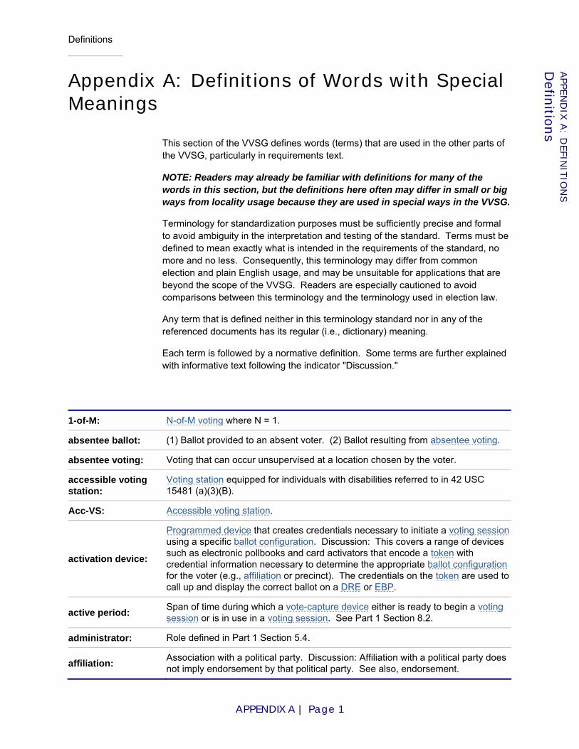
Definitions
APPENDIX A | Page 1
APPE
ND
IX A
: DEFIN
ITIO
NS
Defin
itions
Appendix A: Definitions of Words with Special Meanings
This section of the VVSG defines words (terms) that are used in the other parts of the VVSG, particularly in requirements text.
NOTE: Readers may already be familiar with definitions for many of the words in this section, but the definitions here often may differ in small or big ways from locality usage because they are used in special ways in the VVSG.
Terminology for standardization purposes must be sufficiently precise and formal to avoid ambiguity in the interpretation and testing of the standard. Terms must be defined to mean exactly what is intended in the requirements of the standard, no more and no less. Consequently, this terminology may differ from common election and plain English usage, and may be unsuitable for applications that are beyond the scope of the VVSG. Readers are especially cautioned to avoid comparisons between this terminology and the terminology used in election law.
Any term that is defined neither in this terminology standard nor in any of the referenced documents has its regular (i.e., dictionary) meaning.
Each term is followed by a normative definition. Some terms are further explained with informative text following the indicator "Discussion."
1-of-M: N-of-M voting where N = 1.
absentee ballot: (1) Ballot provided to an absent voter. (2) Ballot resulting from absentee voting.
absentee voting: Voting that can occur unsupervised at a location chosen by the voter.
accessible voting station:
Voting station equipped for individuals with disabilities referred to in 42 USC 15481 (a)(3)(B).
Acc-VS: Accessible voting station.
activation device:
Programmed device that creates credentials necessary to initiate a voting sessionusing a specific ballot configuration. Discussion: This covers a range of devices such as electronic pollbooks and card activators that encode a token with credential information necessary to determine the appropriate ballot configuration for the voter (e.g., affiliation or precinct). The credentials on the token are used to call up and display the correct ballot on a DRE or EBP.
active period: Span of time during which a vote-capture device either is ready to begin a voting session or is in use in a voting session. See Part 1 Section 8.2.
administrator: Role defined in Part 1 Section 5.4.
affiliation: Association with a political party. Discussion: Affiliation with a political party does not imply endorsement by that political party. See also, endorsement.
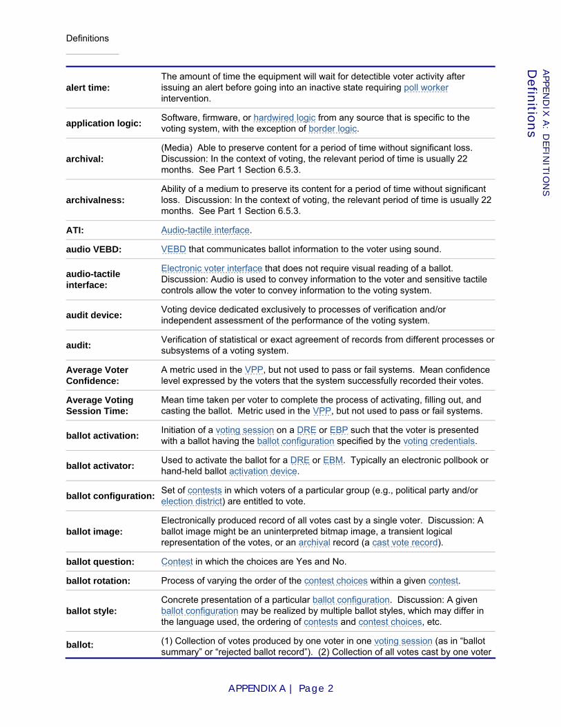
Definitions
APPENDIX A | Page 2
APPE
ND
IX A
: DEFIN
ITIO
NS
Defin
itions
alert time: The amount of time the equipment will wait for detectible voter activity after issuing an alert before going into an inactive state requiring poll worker intervention.
application logic: Software, firmware, or hardwired logic from any source that is specific to the voting system, with the exception of border logic.
archival: (Media) Able to preserve content for a period of time without significant loss. Discussion: In the context of voting, the relevant period of time is usually 22 months. See Part 1 Section 6.5.3.
archivalness: Ability of a medium to preserve its content for a period of time without significant loss. Discussion: In the context of voting, the relevant period of time is usually 22 months. See Part 1 Section 6.5.3.
ATI: Audio-tactile interface.
audio VEBD: VEBD that communicates ballot information to the voter using sound.
audio-tactile interface:
Electronic voter interface that does not require visual reading of a ballot. Discussion: Audio is used to convey information to the voter and sensitive tactile controls allow the voter to convey information to the voting system.
audit device: Voting device dedicated exclusively to processes of verification and/or independent assessment of the performance of the voting system.
audit: Verification of statistical or exact agreement of records from different processes or subsystems of a voting system.
Average Voter Confidence:
A metric used in the VPP, but not used to pass or fail systems. Mean confidence level expressed by the voters that the system successfully recorded their votes.
Average Voting Session Time:
Mean time taken per voter to complete the process of activating, filling out, and casting the ballot. Metric used in the VPP, but not used to pass or fail systems.
ballot activation: Initiation of a voting session on a DRE or EBP such that the voter is presented with a ballot having the ballot configuration specified by the voting credentials.
ballot activator: Used to activate the ballot for a DRE or EBM. Typically an electronic pollbook or hand-held ballot activation device.
ballot configuration: Set of contests in which voters of a particular group (e.g., political party and/or election district) are entitled to vote.
ballot image: Electronically produced record of all votes cast by a single voter. Discussion: A ballot image might be an uninterpreted bitmap image, a transient logical representation of the votes, or an archival record (a cast vote record).
ballot question: Contest in which the choices are Yes and No.
ballot rotation: Process of varying the order of the contest choices within a given contest.
ballot style: Concrete presentation of a particular ballot configuration. Discussion: A given ballot configuration may be realized by multiple ballot styles, which may differ in the language used, the ordering of contests and contest choices, etc.
ballot: (1) Collection of votes produced by one voter in one voting session (as in “ballot summary” or “rejected ballot record”). (2) Collection of all votes cast by one voter
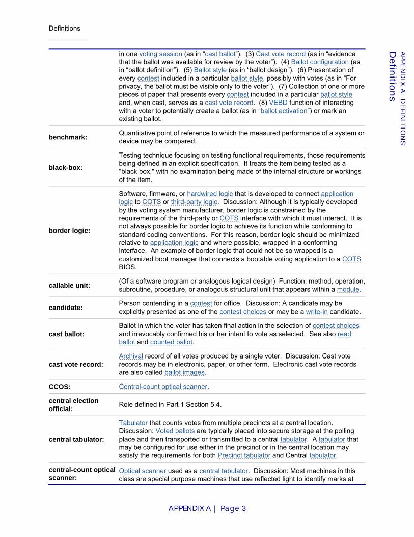
Definitions
APPENDIX A | Page 3
APPE
ND
IX A
: DEFIN
ITIO
NS
Defin
itions
in one voting session (as in “cast ballot”). (3) Cast vote record (as in “evidence that the ballot was available for review by the voter”). (4) Ballot configuration (as in “ballot definition”). (5) Ballot style (as in “ballot design”). (6) Presentation of every contest included in a particular ballot style, possibly with votes (as in “For privacy, the ballot must be visible only to the voter”). (7) Collection of one or more pieces of paper that presents every contest included in a particular ballot style and, when cast, serves as a cast vote record. (8) VEBD function of interacting with a voter to potentially create a ballot (as in “ballot activation”) or mark an existing ballot.
benchmark: Quantitative point of reference to which the measured performance of a system or device may be compared.
black-box:
Testing technique focusing on testing functional requirements, those requirements being defined in an explicit specification. It treats the item being tested as a "black box," with no examination being made of the internal structure or workings of the item.
border logic:
Software, firmware, or hardwired logic that is developed to connect application logic to COTS or third-party logic. Discussion: Although it is typically developed by the voting system manufacturer, border logic is constrained by the requirements of the third-party or COTS interface with which it must interact. It is not always possible for border logic to achieve its function while conforming to standard coding conventions. For this reason, border logic should be minimized relative to application logic and where possible, wrapped in a conforming interface. An example of border logic that could not be so wrapped is a customized boot manager that connects a bootable voting application to a COTS BIOS.
callable unit: (Of a software program or analogous logical design) Function, method, operation, subroutine, procedure, or analogous structural unit that appears within a module.
candidate: Person contending in a contest for office. Discussion: A candidate may be explicitly presented as one of the contest choices or may be a write-in candidate.
cast ballot: Ballot in which the voter has taken final action in the selection of contest choices and irrevocably confirmed his or her intent to vote as selected. See also read ballot and counted ballot.
cast vote record: Archival record of all votes produced by a single voter. Discussion: Cast vote records may be in electronic, paper, or other form. Electronic cast vote records are also called ballot images.
CCOS: Central-count optical scanner.
central election official: Role defined in Part 1 Section 5.4.
central tabulator:
Tabulator that counts votes from multiple precincts at a central location. Discussion: Voted ballots are typically placed into secure storage at the polling place and then transported or transmitted to a central tabulator. A tabulator that may be configured for use either in the precinct or in the central location may satisfy the requirements for both Precinct tabulator and Central tabulator.
central-count optical scanner:
Optical scanner used as a central tabulator. Discussion: Most machines in this class are special purpose machines that use reflected light to identify marks at

Definitions
APPENDIX A | Page 4
APPE
ND
IX A
: DEFIN
ITIO
NS
Defin
itions
specific locations on the ballot. They are designed to read stacks of ballots at a time.
challenged ballot: Ballot cast by a voter whose eligibility to vote is disputed by someone who is not an election official. See also provisional ballot.
choice: Contest choice.
CIF: Common Industry Format.
class: Identified set of voting systems or voting devices sharing a specified characteristic or characteristics. See Part 1 Section 2.5.
closed primary:
Primary election in which the voter receives a ballot containing only those party-specific contests pertaining to the political party with which the voter is affiliated, along with non-party-specific contests presented at the same election. Discussion: Usually, unaffiliated voters are permitted to vote only on non-party-specific contests.
combined precinct: Two or more precincts assigned the same polling place.
Common Industry Format:
Format described in ISO/IEC 25062:2006 "Common Industry Format (CIF) for Usability Test Reports" [ISO06e]. Discussion: CIF is the format required for summative usability test reporting.
completed system response time:
The time taken from when the voter performs some detectible action to when the voting system completes its response and settles into a stable state (e.g., finishes "painting" the screen with a new page).
configuration data: Non-executable input to software, firmware, or hardwired logic, not including vote data.
conformity assessment:
Demonstration that specified requirements relating to a product, process, system, person or body are fulfilled. ([ISO04a])
contest choice: That with which a vote in a given ballot position is associated (e.g., a candidate, or the value Yes or the value No).
contest:
(1) A single decision being put before the voters (e.g., the selection of candidates to fill a particular public office or the approval or disapproval of a constitutional amendment). Discussion: This term subsumes other terms such as "race," "question," and "issue" that are sometimes used to refer to specific kinds of contests. (2) Subdivision of a ballot pertaining to a single decision being put before the voters.
core logic: Subset of application logic that is responsible for vote recording and tabulation.
COTS:
Software, firmware, device or component that is used in the United States by many different people or organizations for many different applications and that is incorporated into the voting system with no manufacturer- or application-specific modification. Discussion: (1) The expansion of COTS as Commercial Off-The-Shelf is no longer helpful, since much of what satisfies the requirements is non-commercial software that is not available in stores. The acronym COTS is used here only because it is familiar to the audience. (2) By requiring "many different applications," this definition deliberately prevents any application logic from receiving a COTS designation.
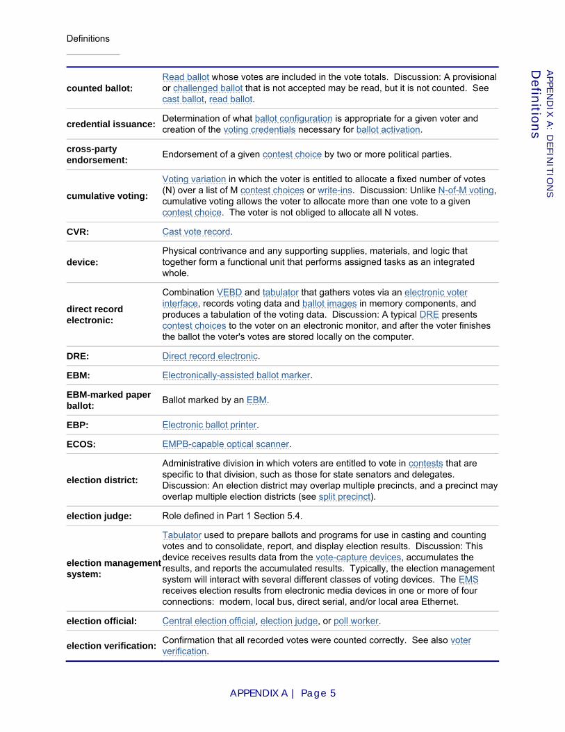
Definitions
APPENDIX A | Page 5
APPE
ND
IX A
: DEFIN
ITIO
NS
Defin
itions
counted ballot: Read ballot whose votes are included in the vote totals. Discussion: A provisional or challenged ballot that is not accepted may be read, but it is not counted. See cast ballot, read ballot.
credential issuance: Determination of what ballot configuration is appropriate for a given voter and creation of the voting credentials necessary for ballot activation.
cross-party endorsement: Endorsement of a given contest choice by two or more political parties.
cumulative voting:
Voting variation in which the voter is entitled to allocate a fixed number of votes (N) over a list of M contest choices or write-ins. Discussion: Unlike N-of-M voting, cumulative voting allows the voter to allocate more than one vote to a given contest choice. The voter is not obliged to allocate all N votes.
CVR: Cast vote record.
device: Physical contrivance and any supporting supplies, materials, and logic that together form a functional unit that performs assigned tasks as an integrated whole.
direct record electronic:
Combination VEBD and tabulator that gathers votes via an electronic voter interface, records voting data and ballot images in memory components, and produces a tabulation of the voting data. Discussion: A typical DRE presents contest choices to the voter on an electronic monitor, and after the voter finishes the ballot the voter's votes are stored locally on the computer.
DRE: Direct record electronic.
EBM: Electronically-assisted ballot marker.
EBM-marked paper ballot: Ballot marked by an EBM.
EBP: Electronic ballot printer.
ECOS: EMPB-capable optical scanner.
election district:
Administrative division in which voters are entitled to vote in contests that are specific to that division, such as those for state senators and delegates. Discussion: An election district may overlap multiple precincts, and a precinct may overlap multiple election districts (see split precinct).
election judge: Role defined in Part 1 Section 5.4.
election management system:
Tabulator used to prepare ballots and programs for use in casting and counting votes and to consolidate, report, and display election results. Discussion: This device receives results data from the vote-capture devices, accumulates the results, and reports the accumulated results. Typically, the election management system will interact with several different classes of voting devices. The EMS receives election results from electronic media devices in one or more of four connections: modem, local bus, direct serial, and/or local area Ethernet.
election official: Central election official, election judge, or poll worker.
election verification: Confirmation that all recorded votes were counted correctly. See also voter verification.
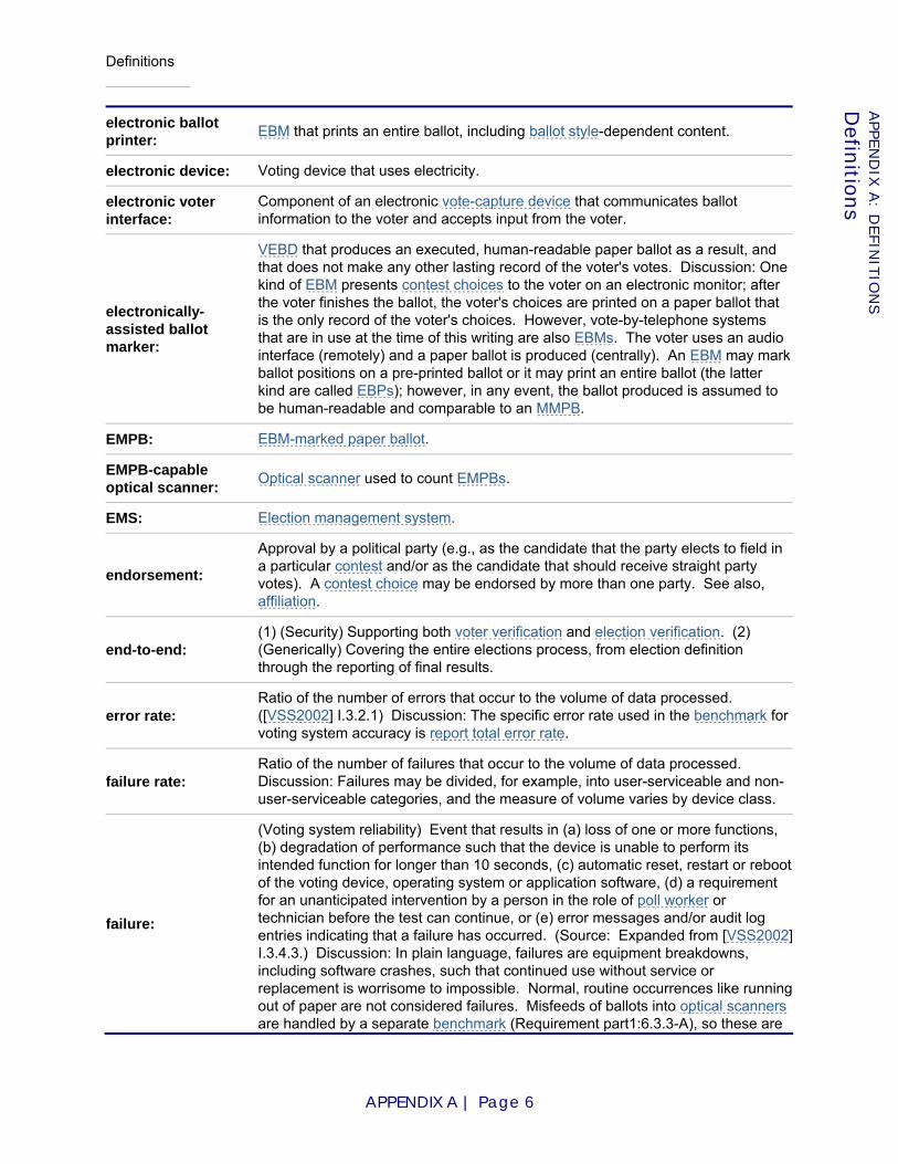
Definitions
APPENDIX A | Page 6
APPE
ND
IX A
: DEFIN
ITIO
NS
Defin
itions
electronic ballot printer: EBM that prints an entire ballot, including ballot style-dependent content.
electronic device: Voting device that uses electricity.
electronic voter interface:
Component of an electronic vote-capture device that communicates ballot information to the voter and accepts input from the voter.
electronically-assisted ballot marker:
VEBD that produces an executed, human-readable paper ballot as a result, and that does not make any other lasting record of the voter's votes. Discussion: One kind of EBM presents contest choices to the voter on an electronic monitor; after the voter finishes the ballot, the voter's choices are printed on a paper ballot that is the only record of the voter's choices. However, vote-by-telephone systems that are in use at the time of this writing are also EBMs. The voter uses an audio interface (remotely) and a paper ballot is produced (centrally). An EBM may mark ballot positions on a pre-printed ballot or it may print an entire ballot (the latter kind are called EBPs); however, in any event, the ballot produced is assumed to be human-readable and comparable to an MMPB.
EMPB: EBM-marked paper ballot.
EMPB-capable optical scanner: Optical scanner used to count EMPBs.
EMS: Election management system.
endorsement:
Approval by a political party (e.g., as the candidate that the party elects to field in a particular contest and/or as the candidate that should receive straight party votes). A contest choice may be endorsed by more than one party. See also, affiliation.
end-to-end: (1) (Security) Supporting both voter verification and election verification. (2) (Generically) Covering the entire elections process, from election definition through the reporting of final results.
error rate: Ratio of the number of errors that occur to the volume of data processed. ([VSS2002] I.3.2.1) Discussion: The specific error rate used in the benchmark for voting system accuracy is report total error rate.
failure rate: Ratio of the number of failures that occur to the volume of data processed. Discussion: Failures may be divided, for example, into user-serviceable and non-user-serviceable categories, and the measure of volume varies by device class.
failure:
(Voting system reliability) Event that results in (a) loss of one or more functions, (b) degradation of performance such that the device is unable to perform its intended function for longer than 10 seconds, (c) automatic reset, restart or reboot of the voting device, operating system or application software, (d) a requirement for an unanticipated intervention by a person in the role of poll worker or technician before the test can continue, or (e) error messages and/or audit log entries indicating that a failure has occurred. (Source: Expanded from [VSS2002] I.3.4.3.) Discussion: In plain language, failures are equipment breakdowns, including software crashes, such that continued use without service or replacement is worrisome to impossible. Normal, routine occurrences like running out of paper are not considered failures. Misfeeds of ballots into optical scanners are handled by a separate benchmark (Requirement part1:6.3.3-A), so these are

Definitions
APPENDIX A | Page 7
APPE
ND
IX A
: DEFIN
ITIO
NS
Defin
itions
not included as failures for the general reliability benchmark.
fault: Flaw in design or implementation that may result in the qualities or behavior of the voting system deviating from the qualities or behavior that are specified in the VVSG and/or in manufacturer-provided documentation.
find: Determine and deliver a finding. (Based on [Oxford93] definition #11.)
finding: Result of a formal evaluation by a test lab or accredited expert; verdict. (Based on [Oxford93] definition #6.)
hardwired logic:
Logic implemented through the design of an integrated circuit; the programming of a Programmable Logic Device (PLD), Field-Programmable Gate Array (FPGA), Peripheral Interface Controller (PIC), or similar; the integration of smaller hardware components; or mechanical design (e.g., as in lever machines).
hesitation mark: Small dot made by resting the point of a writing utensil on a ballot.
implementation statement:
Statement by a manufacturer indicating the capabilities, features, and optional functions and extensions that have been implemented in a voting system.
independent voter-verifiable record:
Record produced by an IVVR vote-capture device supporting voter verification (e.g., VVPAT, EBM). The record contains minimally a summary of the electronic CVR. A voter-verifiable paper record is an independent voter-verifiable record.
initial system response time:
The time taken from when the voter performs some detectible action (such as pressing a button) to when the voting system begins responding in some obvious way (such as an audible response or any change on the screen).
innovation class submission:
Voting system that includes one or more distinct innovative devices. Discussion: See Part 1 Section 2.7.2, Innovation Class Submissions.
in-person: Voting that occurs at a polling place under the supervision of poll workers. Discussion: Also known as poll-site voting.
inspection: Examination of a product design, product, process or installation and determination of its conformity with specific requirements or, on the basis of professional judgment, with general requirements. ([ISO04a])
instant runoff: Ranked order voting.
IVVR vote-capture device:
Vote-capture device that achieves software independence through independent voter-verifiable records.
IVVR: (1) Independent voter-verifiable record. (2) Voting system that achieves software independence through independent voter-verifiable records.
Logic defect: Fault in software, firmware, or hardwired logic.
manually-marked paper ballot:
(1) IVVR vote-capture device consisting of a paper ballot and a writing utensil. (2) Paper ballot that was marked by a person using a writing utensil.
manufacturer: Entity with ownership and control over a voting system submitted for testing.
marginal mark: Mark within a voting target that does not conform to manufacturer specifications for a reliably detectable vote. Discussion: See Part 1 Section 7.7.5.1. The word "marginal" refers to the limit of what is detectable by an optical scanner, not the margin of the page. Marks that are outside of voting targets are called extraneous

Definitions
APPENDIX A | Page 8
APPE
ND
IX A
: DEFIN
ITIO
NS
Defin
itions
marks.
MCOS: MMPB-capable optical scanner.
misfeed rate: Ratio of the misfeed total to the total ballot volume (see Requirement part3:5.3.5-B).
MMPB: Manually-marked paper ballot.
MMPB-capable optical scanner: Optical scanner used to count MMPBs.
module:
Structural unit of software or analogous logical design, typically containing several callable units that are tightly coupled. Discussion: Modular design requires that inter-module coupling be loose and occur over defined interfaces. A module should contain all elements needed to compile or interpret successfully and have limited access to data in other modules. A module should be substitutable with another module whose interfaces match the original module. In software, a module typically corresponds to a single source code file or a source code / header file pair. In object-oriented languages, this typically corresponds to a single class of object.
N-of-M:
Voting variation in which the voter is entitled to allocate a fixed number of votes (N) over a list of M contest choices or write-ins, with the constraint that at most 1 vote may be allocated to a given contest choice. See also cumulative voting. Discussion: The voter is not obliged to allocate all N votes.
non-executable: Declarative or informative in nature; not subject to interpretation or compilation as programming language instructions.
non-party-specific contest:
Contest such that eligibility to vote in that contest is independent of political party affiliation or lack thereof.
observational test:
Operational test conducted on voting devices during an election, by real voters, to establish confidence that the VVPR is produced correctly when assistive technology is used. Discussion: Devices subjected to observational testing are used for normal collection of votes; the votes so collected are included in the election tally.
open primary:
Primary election in which the voter may choose a political party at the time of voting and vote in party-specific contests associated with that party, along with non-party-specific contests presented at the same election. Discussion: Also known as pick-your-party primary. Some states require voters to publicly declare their choice of party at the polling place, after which the poll worker provides or activates the appropriate ballot. Other states allow the voters to make their choice of party within the privacy of the voting booth. Voters also are permitted to vote on non-party-specific contests that are presented at the same election.
operational test: Test conducted on voting equipment in an active (operational) state.
optical scanner: Tabulator that counts votes recorded by means of marks made on the surface of a paper ballot.
paper-based device: Voting device that records votes, counts votes, and/or produces a report of the vote count from votes cast on paper cards or sheets.
party-specific Contest such that eligibility to vote in that contest is restricted based on political
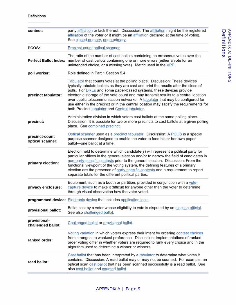
Definitions
APPENDIX A | Page 9
APPE
ND
IX A
: DEFIN
ITIO
NS
Defin
itions
contest: party affiliation or lack thereof. Discussion: The affiliation might be the registered affiliation of the voter or it might be an affiliation declared at the time of voting. See closed primary, open primary.
PCOS: Precinct-count optical scanner.
Perfect Ballot Index: The ratio of the number of cast ballots containing no erroneous votes over the number of cast ballots containing one or more errors (either a vote for an unintended choice, or a missing vote). Metric used in the VPP.
poll worker: Role defined in Part 1 Section 5.4.
precinct tabulator:
Tabulator that counts votes at the polling place. Discussion: These devices typically tabulate ballots as they are cast and print the results after the close of polls. For DREs and some paper-based systems, these devices provide electronic storage of the vote count and may transmit results to a central location over public telecommunication networks. A tabulator that may be configured for use either in the precinct or in the central location may satisfy the requirements for both Precinct tabulator and Central tabulator.
precinct: Administrative division in which voters cast ballots at the same polling place. Discussion: It is possible for two or more precincts to cast ballots at a given polling place. See combined precinct.
precinct-count optical scanner:
Optical scanner used as a precinct tabulator. Discussion: A PCOS is a special purpose scanner designed to enable the voter to feed his or her own paper ballot—one ballot at a time.
primary election:
Election held to determine which candidate(s) will represent a political party for particular offices in the general election and/or to narrow the field of candidates in non-party-specific contests prior to the general election. Discussion: From the functional viewpoint of the voting system, the defining features of a primary election are the presence of party-specific contests and a requirement to report separate totals for the different political parties.
privacy enclosure: Equipment, such as a booth or partition, provided in conjunction with a vote-capture device to make it difficult for anyone other than the voter to determine through visual observation how the voter voted.
programmed device: Electronic device that includes application logic.
provisional ballot: Ballot cast by a voter whose eligibility to vote is disputed by an election official. See also challenged ballot.
provisional-challenged ballot: Challenged ballot or provisional ballot.
ranked order:
Voting variation in which voters express their intent by ordering contest choices from strongest to weakest preference. Discussion: Implementations of ranked order voting differ in whether voters are required to rank every choice and in the algorithm used to determine a winner or winners.
read ballot:
Cast ballot that has been interpreted by a tabulator to determine what votes it contains. Discussion: A read ballot may or may not be counted. For example, an optical scan cast ballot that has been scanned successfully is a read ballot. See also cast ballot and counted ballot.

Definitions
APPENDIX A | Page 10
APPE
ND
IX A
: DEFIN
ITIO
NS
Defin
itions
record: (n) Preserved evidence of activities performed or results achieved (e.g., forms, reports, test results). (v) To create a record.
relevant contest:
Contest appearing in a ballot style or ballot associated with a given reporting context. Discussion: If a contest is included in a ballot style associated with a given reporting context, that contest is relevant even if no ballots of that style were counted.
report total error rate:
Ratio of the report total error to the report total volume (see Requirement part3:5.3.4-B).
report: Self-contained, time stamped, archival record, such as a printout or analogous electronic file that is produced at a specific time and subsequently protected from modification.
reporting context:
Scope within which reported totals or counts are calculated (e.g., precinct or election district). Discussion: Reporting contexts may overlap in complex ways; for example, in the case of split precincts, there is not a simple containment relationship between election districts and precincts.
review-required ballot: Ballot that is flagged or separated for some form of manual processing.
software independence:
Quality of a voting system or voting device such that a previously undetected change or fault in software cannot cause an undetectable change or error in election outcome.
split precinct: Precinct serving voters from two or more administrative divisions, such as election districts, that may require different ballot configurations.
spoil: (A ballot) To mark or otherwise alter a ballot so as to indicate, in a manner supported by the voting system, that the ballot is not to be cast.
straight party override: Explicit vote that conflicts with the vote(s) implied by a straight party vote.
straight party voting:
Voting variation in which a vote in a designated, special contest (in which the choices are political parties) implies votes in accordance with the endorsements of the selected party in all other contents on the ballot in which straight party voting is allowed.
summative usability testing:
Operational testing with representative users and tasks to measure the usability (defined as effectiveness, efficiency and satisfaction) of the complete product. Discussion: The purpose of a summative test is to evaluate a product through defined measures, rather than diagnosis and correction of specific design problems, as in formative testing.
system extent: Administrative unit that is the entire scope within which the voting system is used (e.g., a county). Discussion: The system extent corresponds to the top-level reporting context for which the system generates reports.
tabulator: Programmed device that counts votes. Discussion: Any distinction between processing individual votes and processing vote totals that resulted from a previous step is not relevant; both of these constitute "counting votes."
test method: Description of one or more tests, procedures by which tests are derived, or a
Definitions
APPENDIX A | Page 11
APPE
ND
IX A
: DEFIN
ITIO
NS
Defin
itions
combination of these.
test suite: Implementation of a set of operational tests for a particular object (e.g., a specific voting system) or class of objects (e.g., all voting systems than can interpret the language in which the test data are expressed).
test: Procedure used to determine one or more characteristics of an object of conformity assessment. Discussion: A test may be an operational test or a non-operating test (e.g., an inspection).
testing: Determination of one or more characteristics of an object of conformity assessment, according to a procedure. Discussion: "Testing" typically applies to materials, products or processes. ([ISO04a])
third-party logic:
Software, firmware, or hardwired logic that is neither application logic nor COTS; e.g., general-purpose software developed by a third party that is either customized (e.g., ported to a new platform, as is Windows CE) or not widely used, or source code generated by a COTS package.
token:
Physical device or a digital representation (i.e., a software token) that an authorized user of computer services is given to aid in authentication. Also known as a hardware token, authentication token or cryptographic token. Discussion: A hardware token such as a smartcard is sometimes used to activate the ballot; it contains the voter’s credentials, e.g., information needed to determine the correct ballot style. A smartcard token is sometimes used as an authentication mechanism for voting devices used in the polling place, e.g., a DRE, optical scanner, or electronic pollbook.
Total Completion Score:
The proportion of users who successfully cast a ballot (whether or not the ballot contains erroneous votes). Failure to cast a ballot might involve problems such as a voter simply “giving up” during the voting session because of an inability to operate the system, or a mistaken belief that one has successfully operated the casting mechanism. Metric used in the VPP.
VEBD: Voter-editable ballot device.
VEBD-A: Audio VEBD.
VEBD-V: Video VEBD.
video VEBD: VEBD that communicates ballot information to the voter using light (e.g., via a typical electronic display).
volume test: Test conducted in compliance with Requirement part3:5.2.3-D. Discussion: A volume test involves a large number of "test voters" using voting devices in conditions approximating normal use in an election.
vote: (n) Indication of support for a particular contest choice in a manner supported by the voting system.
vote-capture device: Device that is used directly by a voter to vote a ballot.
voted ballot: Ballot that has been cast or spoiled.
voter inactivity time: The amount of time from when the system completes its response until there is detectible voter activity. In particular, note that audio prompts from the system may take several minutes and that this time does not count as voter inactivity.
Definitions
APPENDIX A | Page 12
APPE
ND
IX A
: DEFIN
ITIO
NS
Defin
itions
Voter Inclusion Index:
A measure of voting accuracy and variance, based on the mean accuracy per voter and the associated standard deviation. Each voter is given a certain number of “voting opportunities” within the ballot. The more of these that are successfully completed, the higher the resulting accuracy for that voter. A metric used in the VPP.
voter verification: Confirmation by the voter that all votes were recorded as the voter intended. See also election verification.
voter: Role defined in Part 1 Section 5.4.
voter-editable ballot device:
Vote-capture device that gathers votes via an electronic voter interface and allows the voter to alter previously made votes without spoiling the ballot.
voter-verifiable paper audit trail:
Voting system that supports voter-verification through voter-verifiable paper records. Discussion: This term is sometimes used incorrectly to describe the paper record produced by the systems, which is more accurately described as a voter-verifiable paper record. This type of voting system can be subdivided into (a) paper-roll approaches that record all VVPRs sequentially on a continuous paper roll, and (b) cut-sheet approaches, which produce separate cut-sheets of paper, each containing a VVPR.
voter-verifiable paper record:
Paper IVVR produced by an IVVR vote-capture device supporting voter verification (e.g., VVPAT, EBM).
voting credentials: Items sufficient to enable a DRE or EBP to activate a ballot of the ballot configuration that is appropriate for a given voter.
voting device:
Device that is part of the voting system. Discussion: Components and materials that are vital to the function of the voting device within the voting system, such as smart cards and ballot printers, are considered parts of the device for the purpose of conformity assessment.
voting performance protocol: Test method that measures how well subjects perform various voting tasks.
voting process: Entire array of procedures, people, resources, equipment and locations associated with the conduct of elections. See also, voting system.
voting session:
(1) Span of time beginning when a ballot is enabled or activated and ending when that ballot is printed (on an EBM), cast (on a DRE), or spoiled. See Part 1 Section 8.2. (2) Interaction between the voter and vote-capture device that occurs during that span of time.
voting station: Vote-capture device, together with its privacy enclosure if it is supposed to have one.
voting system:
Equipment (including hardware, firmware, and software), materials, and documentation used to define elections and ballot styles, configure voting equipment, identify and validate voting equipment configurations, perform logic and accuracy tests, activate ballots, capture votes, count votes, reconcile ballots needing special treatment, generate reports, transmit election data, archive election data, and audit elections. See also, voting process.
voting variation: Voting style, option, or feature such as in-person voting, absentee voting, provisional / challenged ballots, review-required ballots, closed primaries, open

Definitions
APPENDIX A | Page 13
APPE
ND
IX A
: DEFIN
ITIO
NS
Defin
itions
primaries, write-ins, ballot rotation, straight party voting, cross-party endorsement, split precincts, N-of-M voting, cumulative voting, or ranked order voting.
VPP: Voting Performance Protocol.
VVPAT: Voter-verifiable paper audit trail.
VVPR: Voter-verifiable paper record.
white-box:
Testing technique focusing on testing functional requirements, those requirements being defined in an explicit specification. It treats the item being tested as a "black box," with no examination being made of the internal structure or workings of the item.
write-in: Vote for a candidate who is explicitly named by the voter in lieu of choosing a candidate who is already listed on the ballot. Discussion: This does not preclude writing in the name of a candidate who is already listed on the ballot.

VVSG Recommenda t i ons
t o t he EAC
A P P E N D I X B :
References and End Notes
Prepared at the Direction of the
Technical Guidelines Development Committee
August 2007
References
APPENDIX B | Page 1
APPEN
DIX
B: R
EFE
REN
CES
Referen
ces
Appendix B: References and End Notes
ANSI01: American National Standard for Methods of Measurement of Compatibility between Wireless Communication Devices and Hearing Aids, ANSI C63.19-2001.
ANSI02: ANSI/TIA-968-A: 2002, Technical Requirements for Connection of Terminal Equipment to the Telephone Network.
ANSI06: ANSI C84.1:2006, Electric Power Systems and Equipment—Voltage Ratings (60 Hertz).
ANSI06a: CISPR 22 Ed. 5.2 b: 2006, Information technology equipment - Radio disturbance characteristics - Limits and methods of measurement.
ANSI93: ANSI C63.16:1993, American National Standard Guide for Electrostatic Discharge Test – Methodology and Criteria for Electronic Equipment.
ANSI97: CISPR 24 Ed. 1.0 b: 1999, Information technology equipment - Immunity characteristics - Limits and methods of measurement.
CA06: California Volume Reliability Testing Protocol rev. January 31, 2006-01-31. Available from http://www.ss.ca.gov/elections/voting_systems/volume_test_protocol_final.pdf.
CERT06: CERT® Coordination Center, Secure Coding homepage, http://www.cert.org/secure-coding/, July 2006.
DHS06: Department of Homeland Security, Build Security In, https://buildsecurityin.us-cert.gov/, July 2006.
EAC06:
U.S. Election Assistance Commission, Testing and Certification Program Manual, Version 1.0, December 5, 2006. Available from http://www.eac.gov/docs/Voting%20System%20Testing%20and%20Certification%20Program%20Manual--Final%20--120506.pdf.
Epstein55: Benjamin Epstein and Milton Sobel, "Sequential Life Tests in the Exponential Case," Annals of Mathematical Statistics, v. 26, n. 1, March 1955, pp. 82-93.
FCC07: Title 47, Part 15, Rules and Regulations of the Federal Communications Commission, Radio Frequency Devices: 2000.
FCC07a: Title 47, Part 68, Rules and Regulations of the Federal Communications Commission, Connection of Terminal Equipment to the Telephone Network: 2000.
GPO90:
Performance and Test Standards for Punchcard, Marksense, and Direct Recording Electronic Voting Systems, January 1990 edition with April 1990 revisions, in Voting System Standards, U.S. Government Printing Office, 1990.14 Available from http://josephhall.org/fec_vss_1990_pdf/1990_VSS.pdf.
GPO99: Government Paper Specification Standards No. 11, February 1999. Available from http://www.gpo.gov/acquisition/paperspecs.htm.
Grebe96: T.E. Grebe, “Application of Distribution Systems Capacitor Banks and their Impact on Power Quality," IEEE Transactions IA-32, May-June 1996. Available from IEEE. http://www.ieee.org/.

References
APPENDIX B | Page 2
APPEN
DIX
B: R
EFE
REN
CES
Referen
ces
HAVA02: The Help America Vote Act of 2002, Public Law 107-252. Available from http://www.fec.gov/hava/hava.htm.
HFP07: Human Factors and Privacy Subcommittee of the TGDC, “Usability Performance Benchmarks for the VVSG,” August 2007. Available from http://vote.nist.gov/meeting-08172007/Usability-Benchmarks-081707.pdf.
Hoare69: C. A. R. Hoare, "An Axiomatic Basis for Computer Programming," Communications of the ACM, v. 12, n. 10, October 1969, pp. 576-580, 583.
IEEE00: IEEE 100:2000 The Authoritative Dictionary of IEEE Standard Terms, Seventh Edition.
IEEE02: IEEE Std. C62.41.1™:2002 IEEE Guide on the Surge Environment in Low-Voltage (1000 V and less) AC Power Circuits.
IEEE02a: IEEE Std. C62.41.2™:2002 IEEE Recommended Practice on Characterization of Surges in Low-Voltage (1000V and Less) AC Power Circuits.
IEEE02b: IEEE Std. C62.45™:2002 IEEE Recommended Practice on Surge Testing for Equipment Connected to Low-Voltage (1000V and Less) AC Power Circuits
IEEE05: IEEE Std. 1100™:2005 IEEE Recommended Practice for Powering and Grounding Electronic Equipment.
IEEE91: IEEE Std. C62.41™:1991 Recommended Practice for Surge Voltages in Low-Voltage AC Power Circuits.
IEEE92: IEEE Std. 519™:1992 519-1992 IEEE Recommended Practices and Requirements for Harmonic Control in Electrical Power Systems.
IEEE97: IEEE/EIA 12207.1-1997, Industry implementation of International Standard ISO/IEC 12207:1995—(ISO/IEC 12207) standard for information technology—software life cycle processes—life cycle data.
IEEE98: IEEE Std 829-1998, IEEE standard for software test documentation.
ISO00: ISO 9001:2000, Quality management systems – Requirements.
ISO00a: ISO/IEC TR 15942:2000, Information technology—Programming languages—Guide for the use of the Ada programming language in high integrity systems.
ISO01: ISO/IEC 61000-4-2:2001, Electromagnetic compatibility (EMC) - Part 4-2: Testing and measurement techniques - Electrostatic discharge immunity test.
ISO02: ISO 18921:2002, Imaging materials—Compact discs (CD-ROM)—Method for estimating the life expectancy based on the effects of temperature and relative humidity.
ISO03: ISO 10007:2003, Quality management systems – Guidelines for configuration management.
ISO03a: ISO/IEC 14882:2003, Programming languages—C
ISO03b: ISO/IEC 23270:2003, Information technology—C# language specification. Superseded by [ISO06].
ISO04: ISO 8601:2004, Data elements and interchange formats—Information interchange—Representation of dates and times.
References
APPENDIX B | Page 3
APPEN
DIX
B: R
EFE
REN
CES
Referen
ces
ISO04a: ISO 17000:2004, Conformity assessment—Vocabulary and general principles.
ISO04b: ISO/IEC 61000-4-4:2004 Electromagnetic compatibility (EMC) - Part 4-3. Testing and measurement techniques – Electrical fast transient/burst immunity test.
ISO05: ISO 9000:2005, Quality management systems – Fundamentals and vocabulary.
ISO06: ISO/IEC 23270:2006, Information technology—Programming languages—C#.
ISO06a: ISO/IEC 61000-4-3:2006, Electromagnetic compatibility (EMC) - Part 4-3. Testing and measurement techniques - Radiated, radio-frequency, electromagnetic field immunity test.
ISO06b: ISO/IEC 61000-4-6:2006 Electromagnetic compatibility (EMC) - Part 4-6: Testing and measurement techniques - Immunity to conducted disturbances, induced by radio-frequency fields.
ISO06c: ISO/IEC 61000-4-12:2006 Electromagnetic compatibility (EMC) - Part 4-12: Testing and measurement techniques – Ring wave immunity test.
ISO06d: ISO/IEC 61000-4-21:2003 Electromagnetic compatibility (EMC) - Part 4-21. Testing and measurement techniques - Reverberation chamber test methods.
ISO06e: ISO/IEC 25062:2006 Common Industry Format (CIF) for Usability Test Reports.
ISO87: ISO/IEC 8652:1987, Programming languages—Ada. Superseded by [ISO95].
ISO90: ISO/IEC 9899:1990, Programming languages—C. Superseded by [ISO99].
ISO94: ISO 9706:1994, Information and documentation—Paper for documents—Requirements for permanence.
ISO95: ISO/IEC 8652:1995, Information technology—Programming languages—Ada.
ISO95a: ISO/IEC 61000-2-5:1995, Electromagnetic compatibility (EMC) - Part 2-5: Environment –Classification of electromagnetic environments.
ISO98: ISO/IEC 14882:1998, Programming languages—C. Superseded by [ISO03a].
ISO98a: ISO 9241-11:1998, Ergonomic requirements for office work with visual display terminals (VDTs) -- Part 11: Guidance on usability.
ISO99: ISO/IEC 9899:1999, Programming languages—C.
ITIC00: ITI (CBEMA) Curve, Information Technology Industry Council (ITI):2000. Available from ITI, http://www.itic.org/.
java05: The Java Language Specification, Third Edition, 2005. Available from http://java.sun.com/docs/books/jls/index.html.
Key94:
T.S. Key and F.D. Martzloff, “Surging the Upside-Down House: Looking into Upsetting Reference Voltages,” PQA’94 Conference, Amsterdam, Netherlands, 1994. Accessible on-line at the NIST-hosted SPD Anthology – Part 5, http://www.eeel.nist.gov/817/pubs/spd-anthology/methods.html.
KS05: Request For Proposal #08455, Kansas, 2005-05-16. Available from http://www.kssos.org/elections/05elec/Voting_Equipment_RFP.pdf, July 2006.
References
APPENDIX B | Page 4
APPEN
DIX
B: R
EFE
REN
CES
Referen
ces
Martin07: Philippe A. Martin, The Petri Net Linear Form (PNLF), http://www.phmartin.info/wf/pnlf/, 2007.
MIL83: MIL-STD-810-D, Environmental Test Methods and Engineering Guidelines, 1983-7-19.
MIL85: MIL-STD-1521B (USAF) Technical Reviews and Audits for Systems, Equipments [sic], and Computer Software, rev. December 19, 1985.
MIL96: MIL-HDBK-781A, Handbook for Reliability Test Methods, Plans, and Environments for Engineering, Development, Qualification, and Production, April 1, 1996.
MIRA04: MISRA-C:2004: Guidelines for the use of the C language in critical systems, MIRA Limited, U.K., November 2004.
Morris84: F. L. Morris and C. B. Jones, "An Early Program Proof by Alan Turing," IEEE Annals of the History of Computing, v. 6, n. 2, April 1984, pp. 139-143.
Moulding89: M. R. Moulding, "Designing for high integrity: the software fault tolerance approach," Section 3.4. In C. T. Sennett, ed., High-Integrity Software, Plenum Press, New York and London, 1989.
MS05: Request For Proposal #3443, Mississippi, April 28, 2005. Available from http://www.its.state.ms.us/rfps/3443.htm, 2006-07.
MS05: Paul Vick, The Microsoft® Visual Basic® Language Specification, Version 8.0, 2005. Available from Microsoft Download Center, http://go.microsoft.com/fwlink/?linkid=62990.
ND06: Request for Proposals #108.6-03-001, North Dakota, October 31, 2003. Available from http://www.state.nd.us/hava/documents/docs/vsp-rfp-official.pdf, 2006-01-26.
NFPA05: National Electrical Code (NFPA 70):2005. Available from NFPA, http://www.nfpa.org/.
NGC06: Nevada Gaming Commission and State Gaming Control Board, Technical Standards for Gaming Devices and On-Line Slot Systems, March 2006. Available from http://gaming.nv.gov/stats_regs/reg14_tech_stnds.pdf.
NIST02: John P. Wack, Ken Cutler, Jamie Pole, National Institute of Standards and Technology Special Publication 800-41: Guidelines on Firewalls and Firewall Policy, January 2002. Available from http://csrc.nist.gov/publications/nistpubs/800-41/sp800-41.pdf
NIST03: Fred R. Byers, Care and Handling of CDs and DVDs—A Guide for Librarians and Archivists, National Institute of Standards and Technology Special Publication 500-252, 2003-10. Available from http://www.itl.nist.gov/div895/carefordisc/index.html.
NIST05: Recommended Security Controls for Federal Information Systems, National Institute of Standards and Technology Special Publication 800-53, 2005-02. Available from http://csrc.nist.gov/publications/nistpubs/.
NIST05a:
Peter Mell, Karen Kent, Joseph Nusbaum, National Institute of Standards and Technology Special Publication 800-83: Guide to Malware Incident Prevention and Handling, November 2005. Available from http://csrc.nist.gov/publications/nistpubs/800-83/SP800-83.pdf.
NIST07: Karen Scarfone, Peter Mell, National Institute of Standards and Technology Special Publication 800-94: Guide to Intrusion Detection and Prevention Systems, February 2007. Available from http://csrc.nist.gov/publications/nistpubs/800-94/SP800-94.pdf.

References
APPENDIX B | Page 5
APPEN
DIX
B: R
EFE
REN
CES
Referen
ces
NIST75: Saltman, Roy, National Institute of Standards Special Publication 500-30, Effective Use of Computing Technology in Vote-Tallying, 1975. Available from http://csrc.nist.gov/publications/nistpubs/NBS_SP_500-30.pdf
OASIS07: OASIS EML v5.0 Committee Draft, Organization for the Advancement of Structured Information Standards (OASIS), March 2007. Available from http://www.oasis-open.org/committees/download.php/22788/EML%20v5.0%20Committee%20Draft.zip.
OMG07: OMG Unified Modeling Language Superstructure Specification, version 2.1.1. Document formal/2007-02-05, Object Management Group, February 2007. http://www.omg.org/cgi-bin/doc?formal/2007-02-05.
Oxford93: New Shorter Oxford English Dictionary, Clarendon Press, Oxford, 1993.
P1583: IEEE Draft Standard for the Evaluation of Voting Equipment P1583/D5.3.2b, April 1, 2004. Unpublished.
P1622: IEEE Draft Standard for Voting Systems Electronic Data Interchange version 01.003. Information Available from http://grouper.ieee.org/groups/scc38/1622/.
Pietrek97: Matt Pietrek, "A Crash Course on the Depths of Win32™ Structured Exception Handling," Microsoft Systems Journal, January 1997. Available from http://www.microsoft.com/msj/0197/exception/exception.aspx.
Redmill88: F. J. Redmill, Ed., Dependability of Critical Computer Systems 1, Elsevier Applied Science, London and New York, 1988.
Rivest06: Ronald R. Rivest and John P. Wack, “On the notion of "software independence" in voting systems,” July 28, 2006. Available from http://vote.nist.gov/SI-in-voting.pdf.
SCAM01: Joel Scambray, Stuart McClure, George Kurtz, Hacking Exposed: Network Security Secrets and Solutions, Second Edition, 2001.
Sourceforge00: CEXCEPT (exception handling in C), software package, 2000. Available from http://cexcept.sourceforge.net/.
Telcordia06: Telcordia GR-1089:2006, Electromagnetic Compatibility and Electrical Safety - Generic Criteria for Network Telecommunications Equipment. Available from Telcordia, http://telecom-info.telcordia.com/.
UL03: UL 437:2003, Standard for Key Locks. (2003).
UL05: UL 60950-1:2005, Information Technology Equipment – Safety – Part 1: General Requirements.
UL06: UL 943:2006, Standard for Safety for Ground-Fault Circuit-Interrupters.
UT04: Solicitation #DG5502, Utah, 2004-07-09. Available from http://purchasing.utah.gov/BidHeaders/8750.pdf, January 27, 2006.
Valgrind06: Valgrind home page, http://valgrind.org/, July 2006.
VSS2002: 2002 Voting Systems Standards. Available from http://www.eac.gov/election_resources/vss.html.
VVSG2005: 2005 Voluntary Voting System Guidelines, Version 1.0, March 6, 2006. Available from http://www.eac.gov/vvsg_intro.htm.
References
APPENDIX B | Page 6
APPEN
DIX
B: R
EFE
REN
CES
Referen
ces
Wald47: Abraham Wald, Sequential Analysis, John Wiley & Sons, 1947.
End Notes
[1] Visual Basic 8 does not support named block exit, but it does support specifying the kind of block (do loop, for loop, while loop, select, subroutine, function, etc.) from which to exit, which need not be the innermost block.
[2] Specific equipment and materials are identified in order to describe certain procedures. In no case does such identification imply recommendation or endorsement, nor does it imply that the materials or equipment identified are necessarily the best available for the purpose.
[3] A prerequisite for device-level certification would be prescribing a system architecture so that the responsibilities of each device and the interfaces between those devices could be well-specified. Such prescription is undesirable. More importantly, even with a prescribed architecture, a device-level certification would provide no assurance that any particular system that included that component would function as specified. That assurance can only be obtained by evaluating the complete system in the configuration in which it is to be deployed.
[4] Portions of this section are derived from Section 5.6.2.2 of [P1583].
[5] This material is from an unapproved draft of a proposed IEEE Standard, P1583. As such, the material is subject to change in the final standard. Because this material is from an unapproved draft, the IEEE recommends that it not be utilized for any conformance/compliance purposes. It is used at your own risk.
[6] Portions of this section are derived from Sections 5.6.2.2 and 6.6.4.2 of [P1583].
[7] In mathematical jargon, the word domain would be more appropriate than range for input variables; however, "range checking" is the common programming jargon.
[8] These values are derived from category 3K3 of IEC 60721-3-3, which is described as, the product operating in a temperature-controlled enclosed location where the humidity is not controlled. Further, the product is not subject to condensed water or water from other sources.
[9] A compromised device could be programmed to give the correct answers during logic and accuracy testing but behave differently after polls are opened. This kind of fraud is detected and prevented through other means, beginning with the design review specified in Part 3 Section 4.3 and Requirement part1:6.1-A and continuing with setup validation and routine audits.
[10] The reasons that ranked order voting is not handled are discussed in Part 1 Section 7.7.2.5.

References
APPENDIX B | Page 7
APPEN
DIX
B: R
EFE
REN
CES
Referen
ces
[11] A system conforming to the Write-ins class is required to be capable of counting and reporting totals for all candidates that are written in by voters. In some states, write-in votes are not counted unless they exactly match one of a list of registered, accepted write-in candidates. Voting systems may support reporting options that meet the requirements of such states without disruption to the counting logic.
[12] The test lab may rely on media manufacturers' specifications for data retention or life expectancy if accelerated testing results are not available. See also [NIST03], [ISO94] and [ISO02].
[13] Requirement part1:6.6-A.3 and Requirement part1:6.6-A.4 indicate acceptable designs.
[14] The 1990 Voting System Standards package also included "A Plan for Implementing the FEC Voting System Standards," "System Escrow Plan for the Voting System Standards Program," and "A Process for Evaluating Independent Test Authorities.”