Final Revision 1 - kdheks.gov · Final Revision 1 Feasibility Study ... 6-12 7.0 Recommendation of...
161
Final Revision 1 Feasibility Study Report Former Unocal Chemical Distribution Facility Wichita, Sedgwick County, Kansas June 26, 2009 Prepared for: Chevron Environmental Management Company (EMC) 6111 Bollinger Canyon Road San Ramon, CA 94583 Prepared by: URS Corporation 9400 Amberglen Boulevard Austin, Texas 78279
Transcript of Final Revision 1 - kdheks.gov · Final Revision 1 Feasibility Study ... 6-12 7.0 Recommendation of...
Final Revision 1
Feasibility Study Report
Former Unocal Chemical Distribution Facility Wichita, Sedgwick County, Kansas
June 26, 2009
Prepared for:
Chevron Environmental Management Company (EMC) 6111 Bollinger Canyon Road
San Ramon, CA 94583
Prepared by: URS Corporation
9400 Amberglen Boulevard Austin, Texas 78279
Former Unocal - FS Report Page ii Final Revision 1 Wichita, Kansas June 2009
Table of Contents
Section Title Page
1.0 Introduction.......................................................................................................... 1-1 1.1 Site Background................................................................................................... 1-1 1.2 Purpose................................................................................................................. 1-1 1.3 Report Organization............................................................................................. 1-2
2.0 Summary of Remedial Investigation Results....................................................... 2-1 2.1 Conceptual Site Model......................................................................................... 2-1
2.1.1 Overview and History .............................................................................. 2-1 2.1.2 Land and Water Use................................................................................. 2-5
2.1.2.1 Land Use ................................................................................ 2-5 2.1.2.2 Groundwater Use ................................................................... 2-5
2.1.3 Site Geology and Hydrogeology.............................................................. 2-5 2.1.4 Nature and Extent of Contamination ....................................................... 2-6 2.1.5 Contaminant Fate and Transport.............................................................. 2-7
2.2 Remedial Investigation Conclusions.................................................................. 2-11 2.3 Current Groundwater Data................................................................................. 2-12
3.0 Remedial Action Objectives ................................................................................ 3-1 3.1 Development Process........................................................................................... 3-1 3.2 Site-Specific Remedial Action Objectives Discussion ........................................ 3-2 3.3 Site-Specific Remedial Action Objectives........................................................... 3-3
4.0 Identification and Screening of Remedial Action Technologies ......................... 4-1 4.1 General Response Actions ................................................................................... 4-1 4.2 Identification and Screening of Technology Types and Process Options ........... 4-2
4.2.1 Technology Identification Process........................................................... 4-2 4.2.2 Screening Criteria .................................................................................... 4-3
4.3 Technology Screening Results............................................................................. 4-4
5.0 Development of the Remedial Action Alternatives ............................................. 5-1 5.1 Remedial Action Alternatives Assembly............................................................. 5-1 5.2 Descriptions of the Remedial Action Alternatives .............................................. 5-2
5.2.1 Alternative 1: No Action......................................................................... 5-2 5.2.2 Alternative 2: Monitored Natural Attenuation and Environmental Use
Control Program....................................................................................... 5-2 5.2.3 Alternative 3: Enhanced Reductive Dechlorination ............................... 5-3 5.2.4 Alternative 4: Enhanced Reductive Dechlorination and
Phytoremediation ..................................................................................... 5-5 5.3 Evaluation Criteria ............................................................................................... 5-8
6.0 Evaluation and Comparison of Remedial Action Alternatives............................ 6-1 6.1 Alternative 1: No Action..................................................................................... 6-1
6.1.1 Overall Protection of Human Health and Environment........................... 6-1

Former Unocal - FS Report Page iii Final Revision 1 Wichita, Kansas June 2009
6.1.2 Compliance with ARARs ........................................................................ 6-1 6.1.3 Long-Term Effectiveness and Permanence ............................................. 6-2 6.1.4 Reduction in Toxicity, Mobility, or Volume through Treatment ............ 6-2 6.1.5 Short-Term Effectiveness ........................................................................ 6-2 6.1.6 Implementability ...................................................................................... 6-2 6.1.7 Cost .......................................................................................................... 6-2
6.2 Alternative 2: Monitored Natural Attenuation and the Environmental Use Control Program................................................................................................... 6-2 6.2.1 Overall Protection of Human Health and Environment........................... 6-2 6.2.2 Compliance with ARARs ........................................................................ 6-3 6.2.3 Long-Term Effectiveness and Permanence ............................................. 6-4 6.2.4 Reduction in Toxicity, Mobility, or Volume through Treatment ............ 6-4 6.2.5 Short-Term Effectiveness ........................................................................ 6-4 6.2.6 Implementability ...................................................................................... 6-5 6.2.7 Cost .......................................................................................................... 6-5
6.3 Alternative 3: Enhanced Reductive Dechlorination ........................................... 6-5 6.3.1 Overall Protection of Human Health and Environment........................... 6-6 6.3.2 Compliance with ARARs ........................................................................ 6-6 6.3.3 Long-Term Effectiveness and Permanence ............................................. 6-7 6.3.4 Reduction in Toxicity, Mobility or Volume through Treatment ............. 6-7 6.3.5 Short-Term Effectiveness ........................................................................ 6-8 6.3.6 Implementability ...................................................................................... 6-8 6.3.7 Cost .......................................................................................................... 6-8
6.4 Alternative 4: Enhanced Reductive Dechlorination and Phytoremediation ....... 6-8 6.4.1 Overall Protection of Human Health and Environment........................... 6-8 6.4.2 Compliance with ARARs ........................................................................ 6-9 6.4.3 Long-Term Effectiveness and Permanence ........................................... 6-10 6.4.4 Reduction in Toxicity, Mobility, or Volume through Treatment .......... 6-10 6.4.5 Short-Term Effectiveness ...................................................................... 6-11 6.4.6 Implementability .................................................................................... 6-11 6.4.7 Cost ........................................................................................................ 6-12
6.5 Comparative Analysis........................................................................................ 6-12
7.0 Recommendation of the Final Remedial Action Alternative............................... 7-1
8.0 References............................................................................................................ 8-1
Former Unocal - FS Report Page iv Final Revision 1 Wichita, Kansas June 2009
Appendices Appendix A Consent Order Appendix B Identification and Screening of Technologies Appendix C Computer Modeling of Groundwater Phytoremediation Systems Employing
Deep-Rooted Phreatophytic Trees Appendix D Calculations for Predicted Chemicals of Concern Concentration Reduction and
Reinjection Frequency Appendix E Identification of ARARs Appendix F Calculations for Estimated Costs of Remedial Alternatives
List of Tables
Table Title 2-1 Plumelet B Source Area Groundwater Constituents 2-2 Latest Concentrations of Chemicals of Concern in Plumelets 3-1 Development of RAOs 4-1 Technologies Selected for Incorporation into Remedial Alternatives 6-1 Estimated Costs of Remedial Alternatives 6-2 Comparative Analysis of Alternatives
List of Figures Figure Title 1-1 Site Location Map 2-1 Vicinity Map 2-2 Location of Interim Measures 2-3 Top of Weathered Bedrock and Groundwater Flow Directions 2-4 Location of MIP Points and Soil Samples 5-1 Alternative 1: Long-Term Groundwater Monitoring Locations 5-2 Alternative 2: MNA and Long-Term Groundwater Monitoring Locations 5-3 Alternatives 3 and 4: Plumelet A: P-5 Area 5-4 Alternative 3: Plumelet B: Tank Farm Area 5-5 Alternative 3: Plumelet C: MIP-15 Area 5-6 Complete Alternative 3 5-7 Phytoremediation Implementation 5-8 Alternative 4: Plumelet B: Tank Farm Area 5-9 Alternative 4: Plumelet C: MIP-15 Area 5-10 Complete Alternative 4

Former Unocal - FS Report Page v Final Revision 1 Wichita, Kansas June 2009
List of Abbreviations and Acronyms
μg/L micrograms per liter % percent ARAR applicable or relevant and appropriate requirements AST aboveground storage tank bgs below ground surface BTEX benzene, toluene, ethylbenzene, and xylene CA chloroethane CERCLA Comprehensive Environmental Response, Compensation, and Liability Act CFR Code of Federal Regulations Coleman Coleman North East COC chemical of concern COPC constituent of potential concern DCA dichloroethane DCE dichloroethene DP direct-push DPT direct-push technology EMC Environmental Management Corporation EPA U.S. Environmental Protection Agency EPC exposure point concentration EUC Environmental Use Control FRTR Federal Remediation Technologies Roundtable FS Feasibility Study ft feet Harding Harding ESE, Inc. HRC® Hydrogen Release Compound ID Identification KAR Kansas Administrative Regulations KDHE Kansas Department of Health and Environment LTM long-term monitoring MCL maximum contaminant level MIBK 4-methyl-2-pentanone MIP membrane interface probe mg/kg milligrams per kilogram mg/L milligrams per Liter MNA monitored natural attenuation MW monitoring well N Normal NA Not applicable NAPL non-aqueous phase liquid NCP National Contingency Plan ND Not detected NIC North Industrial Corridor O&M operation and maintenance ORP oxidation-reduction potential

Former Unocal - FS Report Page vi Final Revision 1 Wichita, Kansas June 2009
OSHA Occupational Health and Safety Administration OSWER Office of Solid Waste and Emergency Response OU Operable Unit P or PZ piezometer PCE tetrachloroethene POTW Publicly Owned Treatment Works RAGS Risk Assessment Guidance for Superfund RAO remedial action objective RI Remedial Investigation ROD Record of Decision RSK Risk-Based Standards for Kansas SARA Superfund Amendments and Reauthorization Act Smith Smith Environmental Technologies Corporation SVE soil vapor extraction T Transformed TBC To Be Considered TBD To be determined TCA trichloroethane TCE trichloroethene TMB trimethylbenzene UCL upper confidence level UIC Underground Injection Program Unocal Unocal Chemical Distribution Facility URS URS Corporation USD Unified School District USGS United States Geological Survey VOC volatile organic compound

Former Unocal - FS Report Page 1-1 Final Revision 1 Wichita, Kansas June 2009
1.0 Introduction
This Feasibility Study (FS) documents the development and evaluation of remedial action alternatives to address environmental contamination at the former Unocal Chemical Distribution Facility (Unocal) located in Wichita, Sedgwick County, Kansas.
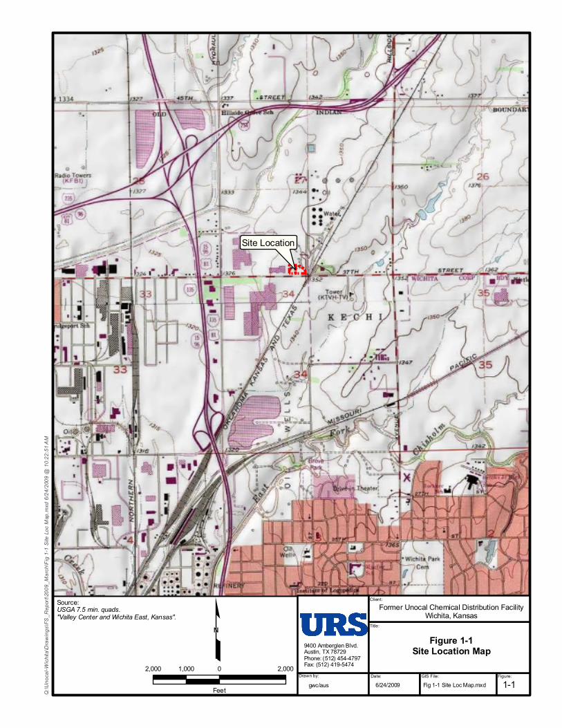
1.1 Site Background The former Unocal Site (referred to as the Site) is located at 2100 E. 37th Street in Wichita, Kansas, and lies approximately 1.3 miles north of the city of Wichita. The 2.4-acre site location is shown on Figure 1-1. The Kansas Department of Health and Environment (KDHE) and Unocal signed a Consent Order on March 23, 1992 that outlined provisions for a Remedial Investigation (RI) and FS to be conducted at the Site and for interim remedial actions to be implemented, as needed (Case Number 91-E-206). This Consent Order requires Unocal to implement “response action(s) to prevent a continuing release or threat of release of hazardous substances and remove the pollution or hazard.” The Consent Order is presented in Appendix A.
On November 21, 2007, URS Corporation (URS) submitted the Final Revision 0 Remedial Investigation (RI) Report, Former Unocal Chemical Distribution Facility, Wichita, Kansas (URS, November 2007) to the KDHE on behalf of Chevron Environmental Management Corporation (EMC). KDHE approved the RI Report in a letter dated December 19, 2007.
On January 17, 2008, KDHE approved Chevron EMC’s request to use the applicable Tier 2 values established in the Risk-Based Standards for Kansas (RSK) Manual in place of site-specific risk-based values derived from a site-specific risk assessment. Therefore, a site-specific risk assessment was not performed for the Site.
1.2 Purpose The purpose of the FS report is to develop and evaluate remedial action alternatives and to recommend a final corrective action to be taken at the Site. In accordance with the Consent Order, the FS was developed in accordance with the Comprehensive Environmental Response, Compensation, and Liability Act (CERCLA) (1980), the Superfund Amendments and Reauthorization Act (SARA) (1986), the National Contingency Plan (NCP), and U.S. Environmental Protection Agency (EPA) Guidance documents. Specifically, the FS addresses the following primary objectives outlined in the Consent Order:
1) To identify and evaluate all appropriate treatment technologies based on information obtained during the RI;

Former Unocal - FS Report Page 1-2 Final Revision 1 Wichita, Kansas June 2009
2) To screen and assemble appropriate technologies into remedial action alternatives;
3) To evaluate and refine alternatives based on the criteria as defined by the relevant EPA guidance documents;
4) To conduct treatability studies or pilot tests to support the effectiveness of certain alternatives; and
5) To recommend the most feasible and effective remedial action for the Site.
This FS is being performed in conjunction with the North Industrial Corridor (NIC) FS. This FS will be performed as per the Consent Order between KDHE and Unocal (Case Number 91-E-206). The evaluation of remedial alternatives in this FS focuses on saturated soil and elevated dissolved-phase groundwater contamination at and near the former Unocal facility. Offsite groundwater contamination in Plumelets A and B has been and is currently addressed by groundwater interim measures “interceptor” system, which is a component of the response actions performed to date. Any contamination beyond the downgradient extent of the IM system will be addressed under the NIC FS as per the North Industrial Corridor Site Settlement Agreement (Case Number 95-E-0321).
1.3 Report Organization In accordance with the KDHE letter dated January 17, 2008, the FS includes:
• References to all interim measures which have been implemented and a discussion of their effectiveness;
• An evaluation of potentially viable remedial technologies to address residual on-site contamination (soil and groundwater); and
• An evaluation of existing off-site groundwater remedial measures to determine whether such measures are effectively addressing off-site groundwater contamination, and how Chevron EMC will coordinate groundwater remedial actions in the context of Operable Unit 1 (OU-1) of the NIC Site.
This FS report is organized into the following sections:
Section 1.0 Introduction Section 2.0 Summary of Remedial Investigation Results Section 3.0 Remedial Action Objectives Section 4.0 Identification and Screening of Remedial Action Technologies Section 5.0 Development of the Remedial Action Alternatives Section 6.0 Evaluation and Comparison of Remedial Action Alternatives
Former Unocal - FS Report Page 1-3 Final Revision 1 Wichita, Kansas June 2009
Section 7.0 Recommendation of the Final Remedial Action Alternative Section 8.0 References Appendix A Consent Order Appendix B Identification and Screening of Technologies Appendix C Computer Modeling of Groundwater Phytoremediation Systems
Employing Deep-Rooted Phreatophytic Trees Appendix D Calculations for Predicted Chemical of Concern Concentration Reduction
and Reinjection Frequency Appendix E Identification of ARARs Appendix F Calculations for Estimated Costs of Remedial Alternatives
Site Location
Former Unocal Chemical Distribution FacilityWichita, Kansas
9400 Amberglen Blvd.Austin, TX 78729Phone: (512) 454-4797Fax: (512) 419-5474
Client:
Title:
Drawn by: Date: GIS File: Figure:1-1gwc/aus
Figure 1-1Site Location Map
2,000 0 2,0001,000
Feet 6/24/2009
£Source:USGA 7.5 min. quads."Valley Center and Wichita East, Kansas".
Q:\U
noca
l-Wich
ita\D
rawing
s\FS_
Repo
rt\20
09_M
arch\F
ig 1-1
Site
Loc M
ap.m
xd 6/
24/20
09 @
10:22
:51 A
M
Fig 1-1 Site Loc Map.mxd
Former Unocal - FS Report Page 2-1 Final Revision 1 Wichita, Kansas June 2009
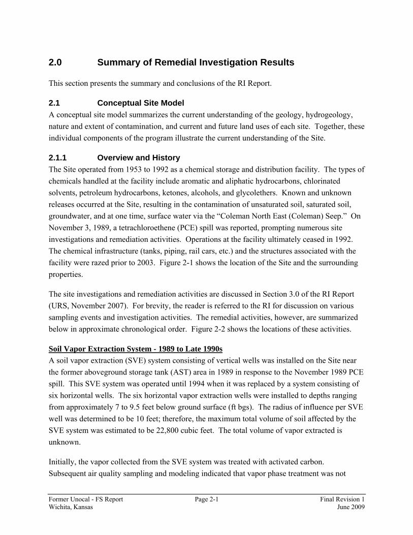
2.0 Summary of Remedial Investigation Results
This section presents the summary and conclusions of the RI Report.
2.1 Conceptual Site Model A conceptual site model summarizes the current understanding of the geology, hydrogeology, nature and extent of contamination, and current and future land uses of each site. Together, these individual components of the program illustrate the current understanding of the Site.
2.1.1 Overview and History The Site operated from 1953 to 1992 as a chemical storage and distribution facility. The types of chemicals handled at the facility include aromatic and aliphatic hydrocarbons, chlorinated solvents, petroleum hydrocarbons, ketones, alcohols, and glycolethers. Known and unknown releases occurred at the Site, resulting in the contamination of unsaturated soil, saturated soil, groundwater, and at one time, surface water via the “Coleman North East (Coleman) Seep.” On November 3, 1989, a tetrachloroethene (PCE) spill was reported, prompting numerous site investigations and remediation activities. Operations at the facility ultimately ceased in 1992. The chemical infrastructure (tanks, piping, rail cars, etc.) and the structures associated with the facility were razed prior to 2003. Figure 2-1 shows the location of the Site and the surrounding properties.
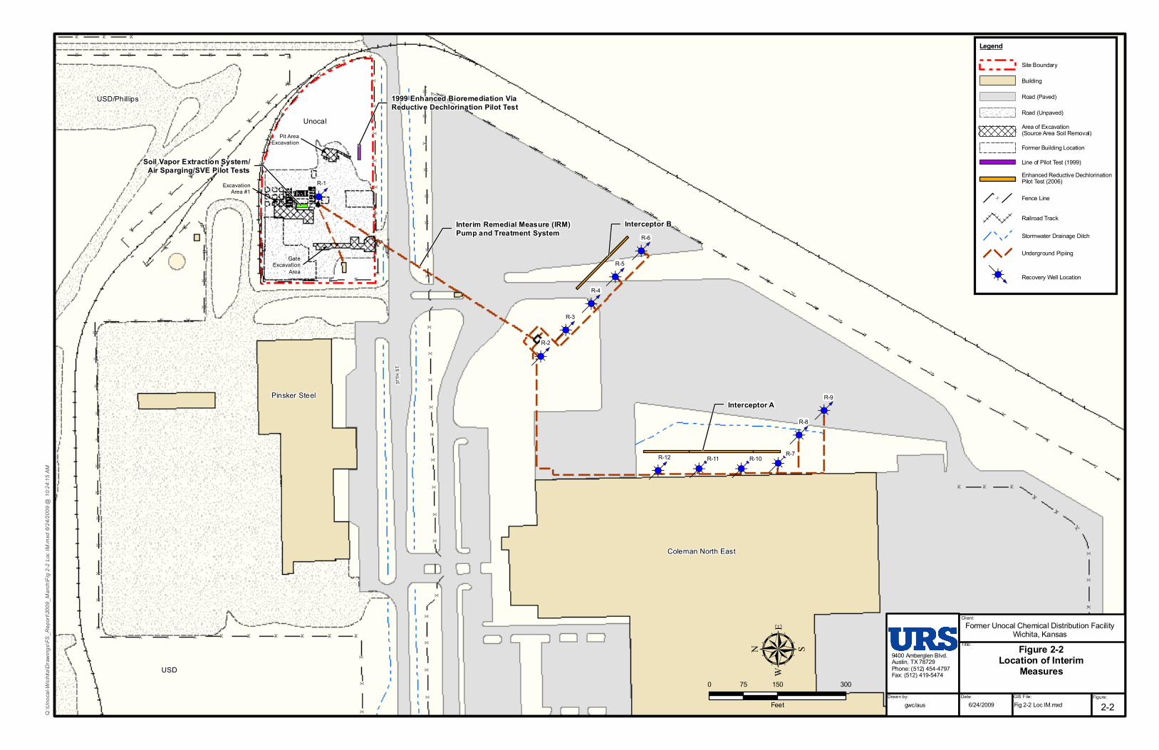
The site investigations and remediation activities are discussed in Section 3.0 of the RI Report (URS, November 2007). For brevity, the reader is referred to the RI for discussion on various sampling events and investigation activities. The remedial activities, however, are summarized below in approximate chronological order. Figure 2-2 shows the locations of these activities.
Soil Vapor Extraction System - 1989 to Late 1990s A soil vapor extraction (SVE) system consisting of vertical wells was installed on the Site near the former aboveground storage tank (AST) area in 1989 in response to the November 1989 PCE spill. This SVE system was operated until 1994 when it was replaced by a system consisting of six horizontal wells. The six horizontal vapor extraction wells were installed to depths ranging from approximately 7 to 9.5 feet below ground surface (ft bgs). The radius of influence per SVE well was determined to be 10 feet; therefore, the maximum total volume of soil affected by the SVE system was estimated to be 22,800 cubic feet. The total volume of vapor extracted is unknown.
Initially, the vapor collected from the SVE system was treated with activated carbon. Subsequent air quality sampling and modeling indicated that vapor phase treatment was not

Former Unocal - FS Report Page 2-2 Final Revision 1 Wichita, Kansas June 2009
necessary, so the use of activated carbon was discontinued. The horizontal SVE system ceased being operated and was decommissioned in the late 1990s. The costs for the vertical and horizontal SVE systems are not known; however, “ballpark” construction cost estimates were performed based on engineering judgment and experience with similar systems. Based on this information, the total cost of the vertical well SVE system was approximately $360,000, while the total cost of the horizontal well SVE system was approximately $250,000. These costs include construction, annual operation and maintenance (O&M), and decommissioning.
Interim Remedial Measure (IRM) Pump and Treatment System - 1994 to August 2006 In 1994, a groundwater extraction system was installed to decontaminate the source area and provide hydraulic control of the dilute portion of the plume. Groundwater was extracted from the Site and the adjacent Coleman property, treated via air stripping, and discharged to the City of Wichita Publicly Owned Treatment Works (POTW). At this time, the seep area was regraded, eliminating the potential for groundwater exposure at the ground surface. However, in 2005, the City of Wichita declined to renew the permit to discharge to the POTW. Accordingly, the extraction system was operated until August 30, 2006 when the permit expired. The system was shut off at that time but still remains in place. A total of 27,871,431 gallons of groundwater was recovered and treated between 1994 and 2006. The total cost of the system was estimated to be approximately $2.7 million, based on system information from 2003 to 2006. This cost includes construction, annual O&M, and decommissioning.
Air Sparging/SVE Pilot Tests - Mid 1990s Two pilot-scale treatability tests, the air sparging and SVE tests, were conducted during the Phase II RI field activities to collect additional data to evaluate these technologies for source area remediation. In certain applications, air sparging has the potential to accelerate remediation of volatile organic compounds (VOCs) in groundwater. Because the results of the air sparge pilot test showed a decrease in VOCs, investigators concluded that air sparging was a promising technology to remediate VOC impacted groundwater.
As mentioned earlier, the SVE pilot test involved the installation of horizontal SVE wells beneath the on-site AST and truck loading areas. The VOCs detected in extracted vapor were similar to the compounds detected in groundwater suggesting that VOCs were being removed from groundwater. However, numerous shutdowns occurred during this test owing to the relatively high amount of rainfall that caused water to be drawn into the system. It was determined that operation of the SVE system was not feasible because the water influx problem would require full-time monitoring of the system to keep it operational (Smith Environmental Technologies Corporation [Smith], December 1996). A minimal volume of soil was treated as part of this SVE Pilot Test.

Former Unocal - FS Report Page 2-3 Final Revision 1 Wichita, Kansas June 2009
The costs for the Air Sparging/SVE Pilot Tests are not known; therefore, a total cost of approximately $100,000 was determined based on engineering judgment and experience with similar pilot tests.
Bioremediation Bench-scale Studies - Mid 1990s Bench-scale studies on four groundwater and soil samples were conducted to determine the feasibility of using bioremediation in conjunction with SVE to remediate contaminated soil and groundwater at the Site. The bioassessment was conducted to characterize the physical, chemical, and biological parameters and identify any parameters that could be toxic to the indigenous microorganisms or could possibly limit the rate or extent of biodegradation. The parameters tested include nutrient analysis, microbial enumeration, and general mineral analyses. Results indicate that the soil and groundwater samples contained a number of indigenous microorganisms that could degrade VOCs. In addition, no compounds inherently toxic to the indigenous microorganisms were found (Smith, December 1996). Other than soil samples, no material was removed and no volume was treated at the Site under this action. The cost for the bioremediation bench-scale studies is not known; therefore, a total cost of approximately $50,000 was determined based on engineering judgment and experience with similar studies.
Enhanced Bioremediation via Reductive Dechlorination Pilot Test- September 1999 to 2006 The objective of this pilot treatability test was to evaluate the efficacy of injecting Hydrogen Release Compound (HRC®) to enhance the naturally occurring, in situ bioattenuation of VOCs at the Site. HRC® is a polylactate ester that breaks down into volatile fatty acids: acetic, butyric, lactic, propionic, and pyruvic. The contaminants of primary interest for this pilot test were PCE, trichloroethene (TCE), cis-1,2-dichloroethene (DCE), and vinyl chloride. The test was conducted in an area free of fuel constituents, just downgradient of the proposed source area for historical Plumelet A (i.e., approximately 85 ft southeast of the AST area). Concentrations of volatile fatty acids, chlorinated ethenes, and the degradation products ethene and ethane were monitored to assess the dechlorination process.
The bioremediation pilot test design consisted of nine injection locations and seven groundwater monitoring piezometers (PZs). On September 28 and 29, 1999, approximately 120 gallons of HRC® were injected into the saturated zone. Groundwater samples were collected from the pilot test PZs monthly from October 1999 to January 2000, in March and May 2000, and on a four-month schedule thereafter. Groundwater monitoring for the pilot study was concluded in September 2000. Contaminant levels fluctuated throughout this time and there were secondary indicators of increased biodegradation. Overall, the enhanced bioremediation pilot test indicated that HRC® injected into the aquifer contributed to a decrease in the concentrations of PCE and TCE in that area (Harding ESE, Inc. [Harding], May 2001). In 2006, the sampling in this area
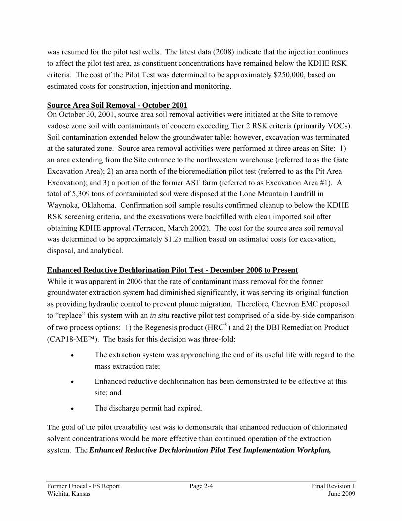
Former Unocal - FS Report Page 2-4 Final Revision 1 Wichita, Kansas June 2009
was resumed for the pilot test wells. The latest data (2008) indicate that the injection continues to affect the pilot test area, as constituent concentrations have remained below the KDHE RSK criteria. The cost of the Pilot Test was determined to be approximately $250,000, based on estimated costs for construction, injection and monitoring.
Source Area Soil Removal - October 2001 On October 30, 2001, source area soil removal activities were initiated at the Site to remove vadose zone soil with contaminants of concern exceeding Tier 2 RSK criteria (primarily VOCs). Soil contamination extended below the groundwater table; however, excavation was terminated at the saturated zone. Source area removal activities were performed at three areas on Site: 1) an area extending from the Site entrance to the northwestern warehouse (referred to as the Gate Excavation Area); 2) an area north of the bioremediation pilot test (referred to as the Pit Area Excavation); and 3) a portion of the former AST farm (referred to as Excavation Area #1). A total of 5,309 tons of contaminated soil were disposed at the Lone Mountain Landfill in Waynoka, Oklahoma. Confirmation soil sample results confirmed cleanup to below the KDHE RSK screening criteria, and the excavations were backfilled with clean imported soil after obtaining KDHE approval (Terracon, March 2002). The cost for the source area soil removal was determined to be approximately $1.25 million based on estimated costs for excavation, disposal, and analytical.
Enhanced Reductive Dechlorination Pilot Test - December 2006 to Present While it was apparent in 2006 that the rate of contaminant mass removal for the former groundwater extraction system had diminished significantly, it was serving its original function as providing hydraulic control to prevent plume migration. Therefore, Chevron EMC proposed to “replace” this system with an in situ reactive pilot test comprised of a side-by-side comparison of two process options: 1) the Regenesis product (HRC®) and 2) the DBI Remediation Product (CAP18-ME™). The basis for this decision was three-fold:
• The extraction system was approaching the end of its useful life with regard to the mass extraction rate;
• Enhanced reductive dechlorination has been demonstrated to be effective at this site; and
• The discharge permit had expired.
The goal of the pilot treatability test was to demonstrate that enhanced reduction of chlorinated solvent concentrations would be more effective than continued operation of the extraction system. The Enhanced Reductive Dechlorination Pilot Test Implementation Workplan,

Former Unocal - FS Report Page 2-5 Final Revision 1 Wichita, Kansas June 2009
Former Unocal Chemical Distribution Facility, Wichita, Kansas (URS, October 2006) was approved by KDHE in October 2006.
HRC® is a proprietary polylactate ester that is manufactured as a viscous gel by Regenesis. CAP18-ME™ is a proprietary vegetable oil product made by DBI Remediation. Both substrates are used to accelerate the in situ biodegradation rates of chlorinated hydrocarbons, such as PCE and TCE, via anaerobic reductive dechlorination processes. CAP18-ME™ is less mobile and thus acts more like a “biobarrier” treatment zone. A detailed description of the HRC® product and the CAP18-ME™ product and their use at the Site was presented in the workplan (URS, October 2006).
The HRC® and CAP18-ME™ were injected into the subsurface on the Coleman site in December 2006 via direct-push technology (DPT) from the top of the lower confining unit to above the estimated potentiometric surface forming two treatment interceptors. DPT had been used previously for the HRC® injection during the 1999 bioremediation pilot test. The treatment interceptors are located upgradient and parallel to each of the two lines of extraction wells. The extraction wells and adjacent monitoring wells are being used to monitor the effectiveness of the pilot test. The results of the pilot test are discussed in the Enhanced Reductive Dechlorination Pilot Test Results Report, Former Unocal Chemical Distribution Facility, Wichita, Kansas (URS, December 2008) that will be submitted to KDHE in December 2008. The cost of the Pilot Test was determined to be approximately $200,000, based on the installation and monitoring costs incurred by Chevron EMC.
2.1.2 Land and Water Use
2.1.2.1 Land Use The current land use for the Site and surrounding area is commercial/industrial. The site lies within an industrial complex, and the intended future land use at the site is anticipated to remain commercial/industrial. The future land use of the entities surrounding the Site (Figure 2-1) is anticipated to remain commercial/industrial.
2.1.2.2 Groundwater Use On-site groundwater is not used for any purpose. Additionally, surrounding properties receive drinking water from the City of Wichita.
2.1.3 Site Geology and Hydrogeology Approximately half of the Site ground cover consists of gravel fill. In regions of the Site where natural ground surface is exposed, the predominate native surface soil to a depth of 2 ft bgs is silty clay. Silt, sand, and gravel lenses of varying thickness comprise the Wisconsinan and
Former Unocal - FS Report Page 2-6 Final Revision 1 Wichita, Kansas June 2009
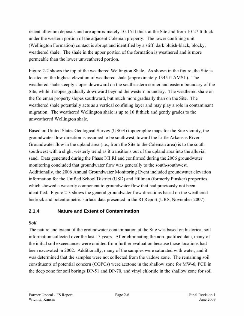
recent alluvium deposits and are approximately 10-15 ft thick at the Site and from 10-27 ft thick under the western portion of the adjacent Coleman property. The lower confining unit (Wellington Formation) contact is abrupt and identified by a stiff, dark bluish-black, blocky, weathered shale. The shale in the upper portion of the formation is weathered and is more permeable than the lower unweathered portion.
Figure 2-2 shows the top of the weathered Wellington Shale. As shown in the figure, the Site is located on the highest elevation of weathered shale (approximately 1345 ft AMSL). The weathered shale steeply slopes downward on the southeastern corner and eastern boundary of the Site, while it slopes gradually downward beyond the western boundary. The weathered shale on the Coleman property slopes southward, but much more gradually than on the Site. The weathered shale potentially acts as a vertical confining layer and may play a role in contaminant migration. The weathered Wellington shale is up to 16 ft thick and gently grades to the unweathered Wellington shale.
Based on United States Geological Survey (USGS) topographic maps for the Site vicinity, the groundwater flow direction is assumed to be southwest, toward the Little Arkansas River. Groundwater flow in the upland area (i.e., from the Site to the Coleman area) is to the south-southwest with a slight westerly trend as it transitions out of the upland area into the alluvial sand. Data generated during the Phase I/II RI and confirmed during the 2006 groundwater monitoring concluded that groundwater flow was generally to the south-southwest. Additionally, the 2006 Annual Groundwater Monitoring Event included groundwater elevation information for the Unified School District (USD) and Hillman (formerly Pinsker) properties, which showed a westerly component to groundwater flow that had previously not been identified. Figure 2-3 shows the general groundwater flow directions based on the weathered bedrock and potentiometric surface data presented in the RI Report (URS, November 2007).
2.1.4 Nature and Extent of Contamination
Soil The nature and extent of the groundwater contamination at the Site was based on historical soil information collected over the last 15 years. After eliminating the non-qualified data, many of the initial soil exceedances were omitted from further evaluation because those locations had been excavated in 2002. Additionally, many of the samples were saturated with water, and it was determined that the samples were not collected from the vadose zone. The remaining soil constituents of potential concern (COPCs) were acetone in the shallow zone for MW-6, PCE in the deep zone for soil borings DP-51 and DP-70, and vinyl chloride in the shallow zone for soil
Former Unocal - FS Report Page 2-7 Final Revision 1 Wichita, Kansas June 2009
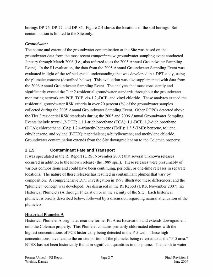
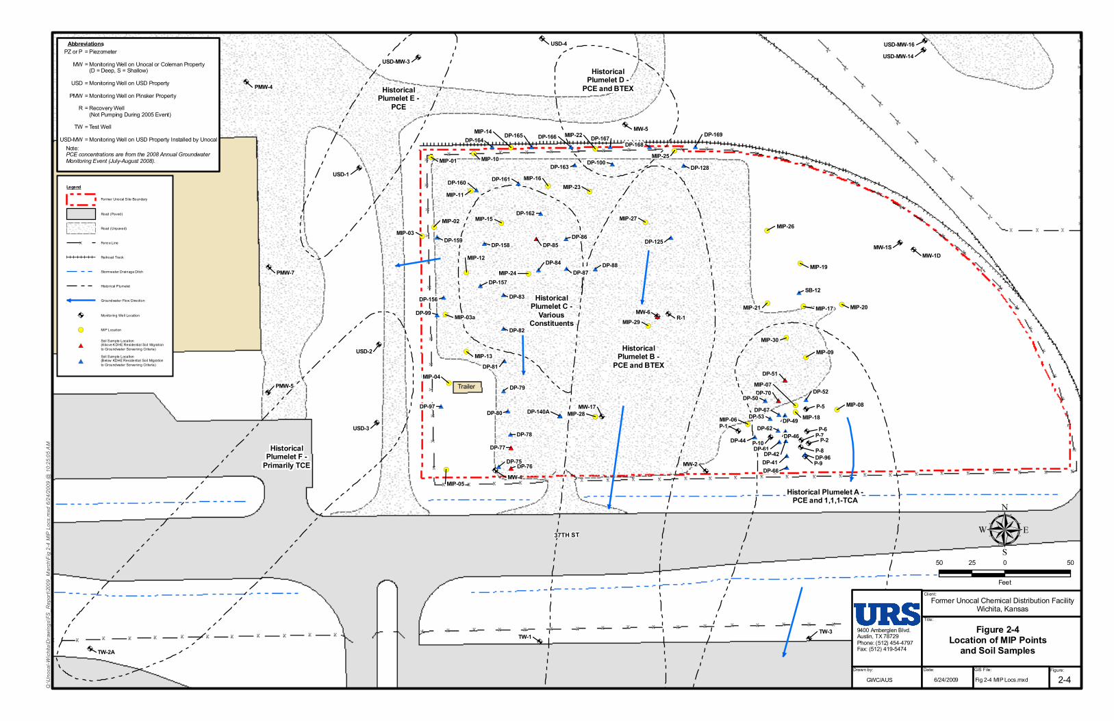
borings DP-76, DP-77, and DP-85. Figure 2-4 shows the locations of the soil borings. Soil contamination is limited to the Site only.
Groundwater The nature and extent of the groundwater contamination at the Site was based on the groundwater data from the most recent comprehensive groundwater sampling event conducted January through March 2006 (i.e., also referred to as the 2005 Annual Groundwater Sampling Event). In the RI evaluation, the data from the 2005 Annual Groundwater Sampling Event was evaluated in light of the refined spatial understanding that was developed in a DPT study, using the plumelet concept (described below). This evaluation was also supplemented with data from the 2006 Annual Groundwater Sampling Event. The analytes that most consistently and significantly exceed the Tier 2 residential groundwater standards throughout the groundwater monitoring network are PCE, TCE, cis-1,2,-DCE, and vinyl chloride. These analytes exceed the residential groundwater RSK criteria in over 20 percent (%) of the groundwater samples collected during the 2005 Annual Groundwater Sampling Event. Other COPCs detected above the Tier 2 residential RSK standards during the 2005 and 2006 Annual Groundwater Sampling Events include trans-1,2-DCE; 1,1,1-trichloroethane (TCA); 1,1-DCE; 1,2-dichloroethane (DCA); chloroethane (CA); 1,2,4-trimethylbenzene (TMB); 1,3,5-TMB; benzene, toluene, ethylbenzene, and xylene (BTEX); naphthalene; n-butylbenzene; and methylene chloride. Groundwater contamination extends from the Site downgradient on to the Coleman property.
2.1.5 Contaminant Fate and Transport It was speculated in the RI Report (URS, November 2007) that several unknown releases occurred in addition to the known release (the 1989 spill). These releases were presumably of various compositions and could have been continuing, periodic, or one-time releases in separate locations. The nature of these releases has resulted in contaminant plumes that vary by composition. A comprehensive DPT investigation in 1997 illustrated these differences, and the “plumelet” concept was developed. As discussed in the RI Report (URS, November 2007), six Historical Plumelets (A through F) exist on or in the vicinity of the Site. Each historical plumelet is briefly described below, followed by a discussion regarding natural attenuation of the plumelets.
Historical Plumelet A Historical Plumelet A originates near the former Pit Area Excavation and extends downgradient onto the Coleman property. This Plumelet contains primarily chlorinated ethenes with the highest concentrations of PCE historically being detected in the P-5 well. These high concentrations have lead to the on-site portion of the plumelet being referred to as the “P-5 area.” BTEX has not been historically found in significant quantities in this plume. The depth to water
Former Unocal - FS Report Page 2-8 Final Revision 1 Wichita, Kansas June 2009
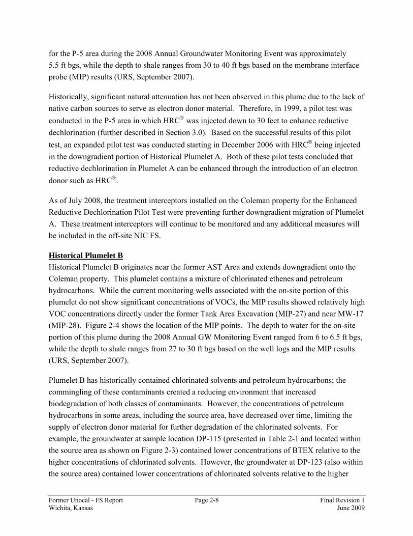
for the P-5 area during the 2008 Annual Groundwater Monitoring Event was approximately 5.5 ft bgs, while the depth to shale ranges from 30 to 40 ft bgs based on the membrane interface probe (MIP) results (URS, September 2007).
Historically, significant natural attenuation has not been observed in this plume due to the lack of native carbon sources to serve as electron donor material. Therefore, in 1999, a pilot test was conducted in the P-5 area in which HRC® was injected down to 30 feet to enhance reductive dechlorination (further described in Section 3.0). Based on the successful results of this pilot test, an expanded pilot test was conducted starting in December 2006 with HRC® being injected in the downgradient portion of Historical Plumelet A. Both of these pilot tests concluded that reductive dechlorination in Plumelet A can be enhanced through the introduction of an electron donor such as HRC®.
As of July 2008, the treatment interceptors installed on the Coleman property for the Enhanced Reductive Dechlorination Pilot Test were preventing further downgradient migration of Plumelet A. These treatment interceptors will continue to be monitored and any additional measures will be included in the off-site NIC FS.
Historical Plumelet B Historical Plumelet B originates near the former AST Area and extends downgradient onto the Coleman property. This plumelet contains a mixture of chlorinated ethenes and petroleum hydrocarbons. While the current monitoring wells associated with the on-site portion of this plumelet do not show significant concentrations of VOCs, the MIP results showed relatively high VOC concentrations directly under the former Tank Area Excavation (MIP-27) and near MW-17 (MIP-28). Figure 2-4 shows the location of the MIP points. The depth to water for the on-site portion of this plume during the 2008 Annual GW Monitoring Event ranged from 6 to 6.5 ft bgs, while the depth to shale ranges from 27 to 30 ft bgs based on the well logs and the MIP results (URS, September 2007).
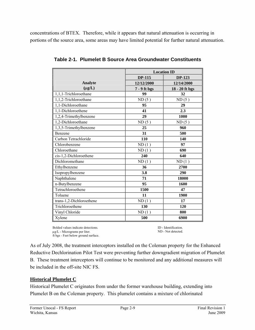
Plumelet B has historically contained chlorinated solvents and petroleum hydrocarbons; the commingling of these contaminants created a reducing environment that increased biodegradation of both classes of contaminants. However, the concentrations of petroleum hydrocarbons in some areas, including the source area, have decreased over time, limiting the supply of electron donor material for further degradation of the chlorinated solvents. For example, the groundwater at sample location DP-115 (presented in Table 2-1 and located within the source area as shown on Figure 2-3) contained lower concentrations of BTEX relative to the higher concentrations of chlorinated solvents. However, the groundwater at DP-123 (also within the source area) contained lower concentrations of chlorinated solvents relative to the higher
Former Unocal - FS Report Page 2-9 Final Revision 1 Wichita, Kansas June 2009
concentrations of BTEX. Therefore, while it appears that natural attenuation is occurring in portions of the source area, some areas may have limited potential for further natural attenuation.
Table 2-1. Plumelet B Source Area Groundwater Constituents
Location ID
DP-115 DP-123 12/12/2000 12/14/2000 Analyte
(μg/L) 7 - 9 ft bgs 18 - 20 ft bgs 1,1,1-Trichloroethane 99 32 1,1,2-Trichloroethane ND (5 ) ND (5 ) 1,1-Dichloroethane 95 29 1,1-Dichloroethene 41 2.3 1,2,4-Trimethylbenzene 29 1000 1,2-Dichloroethane ND (5 ) ND (5 ) 1,3,5-Trimethylbenzene 25 960 Benzene 31 500 Carbon Tetrachloride 110 140 Chlorobenzene ND (1 ) 97 Chloroethane ND (1 ) 690 cis-1,2-Dichloroethene 240 640 Dichloromethane ND (1 ) ND (1 ) Ethylbenzene 36 2700 Isopropylbenzene 3.8 290 Naphthalene 71 18000 n-Butylbenzene 95 1600 Tetrachloroethene 1500 47 Toluene 11 1900 trans-1,2-Dichloroethene ND (1 ) 17 Trichloroethene 130 120 Vinyl Chloride ND (1 ) 800 Xylene 500 6900
Bolded values indicate detections. μg/L - Micrograms per liter. ft bgs - Feet below ground surface.
ID - Identification. ND - Not detected.
As of July 2008, the treatment interceptors installed on the Coleman property for the Enhanced Reductive Dechlorination Pilot Test were preventing further downgradient migration of Plumelet B. These treatment interceptors will continue to be monitored and any additional measures will be included in the off-site NIC FS.
Historical Plumelet C Historical Plumelet C originates from under the former warehouse building, extending into Plumelet B on the Coleman property. This plumelet contains a mixture of chlorinated

Former Unocal - FS Report Page 2-10 Final Revision 1 Wichita, Kansas June 2009
ethenes/ethanes and petroleum hydrocarbons. Based on the MIP results and the associated groundwater grab samples, the highest concentrations of VOCs were observed near the MIP-15 location (Figure 2-3). The depth to water in this area based on the MIP results is estimated to around 6 ft bgs, while the depth to shale is around 18 ft bgs.
The source area for historical Plumelet C has significant concentrations of both petroleum hydrocarbons and chlorinated solvents, thereby causing a reducing environment and increasing the biodegradation component of natural attenuation, which has limited the extent of this plumelet.
Historical Plumelet D Historical Plumelet D is confined to the area north from the center of the northern site boundary (near MW-5). This plume historically contained PCE and BTEX. The source of these constituents may be associated with Plumelet B, although no direct connection has been found through investigation. For MW-5, concentrations of PCE, TCE, and vinyl chloride have decreased from approximately 1,000 micrograms per liter (μg/L) (at various times) to less than 88 μg/L, 60 μg/L, and 80 μg/L, respectively, in 2008. The degradation compound cis-1,2-DCE was detected at a concentration of 2,400 μg/L in 1994, but has only decreased to 640 μg/L by the 2008 Annual GW Monitoring Event. In 2008, the Mann-Kendall trends for this well were downward for all of these constituents.
Although BTEX concentrations have fluctuated over the years, they appeared to have a general downward trend from the mid-1990s until 2006, when a spike in concentrations of ethylbenzene, toluene, and xylenes occurred. Therefore, the Mann-Kendall tests show an undetermined trend for all constituents other than benzene, which shows a downward trend.
Historical Plumelet E Historical Plumelet E is confined to the area northwest of the northwest corner of the Site. The source of these constituents may be associated with Plumelet C, although no direct connection has been found through investigation. The MIP investigation did not indicate a clear connection between the two plumelets along the northern and western boundaries of the Site. There are also geochemical differences in these two plumelets. The monitoring wells in this plume, USD-MW-3 and USD-1, historically contained mostly PCE. TCE has not been found historically in significant quantities in this plume.
Historical Plumelet F Historical Plumelet F is located to the west-southwest of the western site boundary. The source of these constituents may also be associated with Plumelet C, although no direct connection has been found through investigation. The MIP investigation did not indicate a clear source of

Former Unocal - FS Report Page 2-11 Final Revision 1 Wichita, Kansas June 2009
contamination present along the western boundary of the Site. There are also geochemical differences in these two plumelets. This plume historically contained primarily TCE with relatively lower concentrations of PCE.
Natural Attenuation The processes described in Section 5.0 of the RI Report governed the fate and transport of constituents released to the environment. The historical plumelets remained segregated as they traveled in a mostly linear fashion in a downgradient direction. Since the source contaminant masses are apparently finite, the plumelets have approached an equilibrium state. At this time, the natural attenuation processes are in balance with continuing dissolution to the groundwater at the source areas. The presence of degradation products of chlorinated solvents (e.g., cis-1,2-DCE and vinyl chloride) from the time of the initial sampling efforts until today indicates that natural attenuation is an ongoing process.
Chevron EMC prepared a detailed description of the site’s 2005 monitored natural attenuation (MNA) evaluation, which was documented in the Final Revision 0, Former Unocal Remedial Investigation (RI) Report, November 2007 (URS, November 2007). In that report, multiple lines of evidence were evaluated in accordance with the Bureau of Environmental Remediation Policy # BER-RS-042, Monitored Natural Attenuation, and consultation with KDHE. The description provided in the RI Report showed primary and secondary lines of evidence for MNA, including geochemical and indicator parameter results.
Natural attenuation processes are accountable for considerable decreases in both fuel and chlorinated solvent constituents along portions of the plume. The contaminant plume can be characterized by decreasing concentrations of chlorinated solvents and reductive by-products that occur over a relatively widespread area, mixed with residual concentrations of fuel constituents. Reductive dechlorination has occurred in all portions of the various historical plumelets, but it appears most pronounced in the areas where fuels and solvents were mixed.
The removal of secondary sources contributed to altering the balance such that natural attenuation could overtake the rate of dissolution to the groundwater. Owing to the effects of the groundwater extraction system, pilot tests, and the excavation of contaminated soil at the Site, groundwater concentrations of all constituents have declined throughout this decade.
2.2 Remedial Investigation Conclusions On November 21, 2007, URS submitted the RI Report (URS, November 2007) to the KDHE on behalf of Chevron EMC. KDHE approved the RI Report in a letter dated December 19, 2007.

Former Unocal - FS Report Page 2-12 Final Revision 1 Wichita, Kansas June 2009
Based on the information provided in the RI Report, it appears that the contaminant plumes have reached stability and, owing to removal and interim actions, concentrations continue to decrease. In areas where fuel constituents and solvents coexist, accelerated biodegradation is occurring. For the remainder of the chlorinated solvent plume, reductive dechlorination appears to be limited by the availability of electron donor material. Based on the results of the 1999 and 2006 Pilot Tests, providing donor material has enhanced reductive dechlorination, lowering PCE and TCE concentrations to below regulatory standards for residential use.
2.3 Current Groundwater Data Since the submittal of the RI Report, additional groundwater data have been collected during the 2007 and 2008 Annual Groundwater Monitoring Events and the MIP event. Using this current information, Table 2-2 lists the sample location (monitoring well or groundwater grab) for each Plumelet with the maximum concentrations for the primary contaminants. This information, along with the historical groundwater data presented in the RI Report, was used to develop the remedial alternatives presented in Section 5.0 and during the evaluation of those alternatives in Section 6.0.

Former Unocal - FS Report Page 2-13 Final Revision 1 Wichita, Kansas June 2009
Table 2-2. Latest Concentrations of Chemicals of Concern in Plumelets
Plumelet A B C D E F
Maximum ConcentrationSample Location P-5 MW-6 MIP-15 MW-5 USD-1 USD-2 Analyte
(μg/L)
Residential KDHEScreening Value
(μg/L) Latest Sampling Event Aug-08 Jun-07 Jul-07 Aug-08 Aug-08 Aug-08 Tetrachloroethene 5 1,700 ND (10) 27,000 88 55 21 Trichloroethene 5 610 ND (10) 27,000 60 2.2 170 Vinyl chloride (Chloroethene) 2 6.3 490 240 J 80 ND (0.1) ND (0.5)cis-1,2-Dichloroethene 70 380 8,100 3,500 640 0.3 110 Naphthalene 3 ND (1.0) 510 53 J 1.6 ND (0.1) 0.7 J 1,2,4-Trimethylbenzene 5 ND (1.0) 250 290 8.5 ND (0.1) ND (0.5)1,1-Dichloroethene 7 2.1 290 3,000 1.4 ND (0.1) 2 J 1,3,5-Trimethylbenzene 5 ND (1.0) 52 79 J 1.3 ND (0.1) ND (0.5)Benzene 5 ND (1.0) 10 J 940 1.0 J ND (0.1) ND (0.5)Ethylbenzene 700 ND (1.0) 3,200 1,700 280 ND (0.1) ND (0.5)1,2-Dichloroethane 5 ND (1.0) ND (10) 19,000 ND (0.5) ND (0.1) ND (0.5)1,1,1-Trichloroethane 200 17 84 510 ND (0.5) ND (0.1) ND (0.5)Chloroethane (Ethyl chloride) 48 ND (1.0) ND (10) ND (50) 0.7 J ND (0.1) ND (0.5)trans-1,2-Dichloroethene 100 5.3 110 ND (50) 5.5 ND (0.1) 1.1 J n-Butylbenzene 21 ND (1.0) 12 J ND (50) ND (0.5) ND (0.1) ND (0.5)4-Methyl-2-pentanone (MIBK) 70 ND (10) ND (100) 1,700 J ND (5.0) ND (1.0) ND (5.0)
Bold and Shaded Values exceed Residential KDHE Screening Value. J - The analyte was positively identified, the quantitation is an estimate. μg/L Micrograms per Liter. ND (#) - Non-detect (Reporting Limit).

Coleman North East
Unified School District (USD)
Pinsker Steel
Unocal
USD/Phillips
USD/Phillips
RetentionPond
Conoco-Phillips
I135 RAM P
I135 R
AMP
K96 RAMP
39TH ST
K96 RAMP
I1 3 5HWY
I1 3 5 HWY
POPL
ARST 36TH CIR
HYDR
AULIC
AVE
37TH ST
9400 Amberglen Blvd.Austin, TX 78729Phone: (512) 454-4797Fax: (512) 419-5474
Title:
Drawing File:Drawn by: Date:
Former Unocal Chemical Distribution FacilityWichita, Kansas
Figure 2-1Vicinity Map
0 400 800200
Feet
³
Legend
Site Boundary
Adjacent Parcel Boundaries
Road (Unpaved)
Stormwater Drainage Ditch
Railroad Track
Client:
2-1gwc/ausDrawing File:Drawing File: Figure:
6/24/2009
Q:\U
noca
l-Wich
ita\D
rawing
s\FS_
Repo
rt\20
09_M
arch\F
ig 2-1
SVM
.mxd
6/24
/2009
@ 10
:23:34
AM
Fig 2-1 SVM.mxd
X,X,
X,X,X,X,
X,
X,
X,
X,
X,
X,Coleman North East
USD
Pinsker Steel
USD/Phillips
UnocalPit Area
Excavation
ExcavationArea #1
GateExcavation
Area
1999 Enhanced Bioremediation ViaReductive Dechlorination Pilot Test
Interim Remedial Measure (IRM)Pump and Treatment System
Interceptor B
Interceptor A
Soil Vapor Extraction System/Air Sparging/SVE Pilot Tests
37TH
ST
R-1
R-6
R-2
R-3
R-4
R-5
R-12 R-11 R-10 R-7
R-8
R-9
0 150 30075
Feet
µ 9400 Amberglen Blvd.Austin, TX 78729Phone: (512) 454-4797Fax: (512) 419-5474
Client:
Title:
Drawn by: Date: GIS File: Figure:
2-2gwc/aus
Former Unocal Chemical Distribution FacilityWichita, Kansas
Figure 2-2Location of Interim
Measures
Legend
Site Boundary
Building
Road (Paved)
Road (Unpaved)Area of Excavation(Source Area Soil Removal)
Former Building Location
Line of Pilot Test (1999)Enhanced Reductive DechlorinationPilot Test (2006)
X Fence Line
Railroad Track
Stormwater Drainage Ditch
Underground Pipiing
X, Recovery Well Location
6/24/2009
Q:\U
noca
l-Wich
ita\D
rawing
s\FS_
Repo
rt\20
09_M
arch\F
ig 2-2
Loc I
M.mx
d 6/24
/2009
@ 10
:24:15
AM
Fig 2-2 Loc IM.mxd

!(!(
!(!(
!(!(
!(!(
!(!(
!(
!(!(
!(
!(
!(!(
!(
!(
!(!(
!(
!(
!(
!(
!(
!(!(
!( !(!(!(!(
!(!(!( !(
!(
!(!(
!(
!(
!(
!(
!(
!(
!(
!(
!(
!(
!(
!(!(
!(
!(
!(
!(
!(
!(
!(
!(!(!(
!(
!(
!(
!(
!(
!(
!(
!(
!(
!(
!(
!(
!(!(
!(
!(
!( !(
!(!(
1332
1332
1336 1334
1334
1316
1316
1320
1320
1326
1326
1330
1330
1324
1324
1328
1328
1318
1318
1322
1322
1338
1338
1340
1308
1308
1310
1310
1314
1306
1312
1312
1342
1314
1316
1344
1312
1302
1300
1298
1304
1332
1310
37TH
ST
1325.91325.9
1335.51336.1
1330.5
1320.4
1311.3
1322.6
1317.8
1321.9
1311.2
1335
1301.9
1303.9
1307.9
1317.5
1317.4
1316.3
1319.1
1312.1
1316.8 1315.7 1312.2
1328.5
1305.6
1320.3
1335.9
1338.61341.1
1331.4
1332.1 1324.1
1297.51319.6
1321.2
1327.41325.9
1316.2
1311.9
1325.4
1320.1
1305
1305.7
1343.51337
1337.3
1342.11341.3
1345.3 1343.1
1342.6 1342.8
1337.3 1337.1
1337.31336.81336.3
1338.6
1337.1
1329.4
1310.6
1322.7
1341.5
1341.2
1344.41342.5
1341.8 1343.6
1334.2
1336.7
1338
1321.4
1341.4
1320.6
1317.1
1324
1308.7
1322.9
1323.8
1337.91335.8
1320.4
1320.6
9400 Amberglen Blvd.Austin, TX 78729Phone: (512) 454-4797Fax: (512) 419-5474
Client:
Title:
Drawn by: Date:gwc/aus
0 150 30075
Feet
µ
Note:Red contours are higher elevations,while green contours are lower elevations.
Legend
Site Boundary
Building
Road (Paved)
Road (Unpaved)
X Fence Line
Railroad Track
Stormwater Drainage Ditch
Historical Plumelet
Groundwater Flow Direction
!(Boring Location with Shale Elevation(ft AMSL)
6/24/2009
Q:\U
noca
l-Wich
ita\D
rawing
s\FS_
Repo
rt\20
09_M
arch\F
ig 2-3
Bed
rock.m
xd 6/
24/20
09 @
10:24
:38 A
M
GIS File: Figure:
2-3
Former Unocal Chemical Storage FacilityWichita, KansasFigure 2-3
Top of Weathered Bedrockand Groundwater Flow
DirectionsFig 2-3 Bedrock.mxd
!A
!A
!A
!A
!A
!A
!A
!A
!A
!A
!A
!A
!A
!A!A
!A
!A
!A
!A!A
!A
!A
!A
!A
!A!A
!A
!A
!A
!A
!A
!A
!A
!A
#*
#*
#*
#*#*#*#*
#*
#*#*
#*
#*
#*
#*
#*
#*
#*
#*
#*
#*
#*
#* #*
#*
#*
#*
#*
#*
#*
#*
#*
#* #*
#* #*
#*
#*
#* #*
#*#*
#*
#*#*
#*#*
#*
#*
#* #* #* #* #* #*
#*
#*
#*
#*
#*
#*
!(
!(
!(
!(
!(
!(!(
!(
!(
!(
!(
!(
!(
!(
!(
!(
!(
!(
!(
!(
!(!(
!(
!(
!(!(
!(
!(
!(
!(
!(
Historical Plumelet A -PCE and 1,1,1-TCA
HistoricalPlumelet B -
PCE and BTEX
HistoricalPlumelet D -
PCE and BTEX
HistoricalPlumelet C -
VariousConstituents
HistoricalPlumelet E -
PCE
HistoricalPlumelet F -
Primarily TCE
Trailer
USD-3
USD-2
USD-1
TW-3
TW-2A
TW-1
R-1
PMW-5
PMW-4
P-9P-8
P-7P-6
P-5
P-2P-10
P-1
MW-5
MW-4
USD-MW-3
MW-2
MW-1SMW-1D
MW-17
USD-MW-16USD-MW-14
PMW-8
PMW-7
USD-4
MW-6
DP-85
DP-169DP-168
DP-167DP-166DP-165DP-164
DP-163
DP-162
DP-161DP-160
DP-159 DP-158
DP-157
DP-156SB-12
DP-99
DP-97
DP-96
DP-88DP-87
DP-86
DP-84
DP-83
DP-82
DP-81
DP-80
DP-79
DP-78DP-77
DP-76DP-75
DP-70
DP-67
DP-66
DP-62
DP-61
DP-53
DP-52
DP-51
DP-50
DP-49
DP-46DP-44DP-42DP-41
DP-140A
DP-128
DP-125
DP-100
MIP-30
MIP-29
MIP-28
MIP-24
MIP-23
MIP-22
MIP-25
MIP-27MIP-26
MIP-21 MIP-20
MIP-18
MIP-19
MIP-17
MIP-14
MIP-16
MIP-15
MIP-13
MIP-12
MIP-11
MIP-10
MIP-09
MIP-03a
MIP-06
MIP-07
MIP-08
MIP-05
MIP-04
MIP-03MIP-02
MIP-01
37TH ST
= Piezometer= Monitoring Well on Unocal or Coleman Property (D = Deep, S = Shallow)= Monitoring Well on USD Property= Monitoring Well on Pinsker Property= Recovery Well (Not Pumping During 2005 Event)= Test Well= Monitoring Well on USD Property Installed by Unocal
PZ or PMW
USDPMW
R
TWUSD-MW
Abbreviations
Note:PCE concentrations are from the 2008 Annual GroundwaterMonitoring Event (July-August 2008).
9400 Amberglen Blvd.Austin, TX 78729Phone: (512) 454-4797Fax: (512) 419-5474
Client:
Title:
Drawn by: Date:
GWC/AUS
Former Unocal Chemical Distribution FacilityWichita, Kansas
Q:\U
noca
l-Wich
ita\D
rawing
s\FS_
Repo
rt\20
09_M
arch\F
ig 2-4
MIP
Locs
.mxd
6/24
/2009
@ 10
:25:05
AM
50 0 5025
Feet
µ
Legend
Former Unocal Site Boundary
Road (Paved)
Road (Unpaved)
X Fence Line
Railroad Track
Stormwater Drainage Ditch
Historical Plumelet
Groundwater Flow Direction
!A Monitoring Well Location
!( MIP Location
#*Soil Sample Location(Above KDHE Residential Soil Migrationto Groundwater Screening Criteria)
#*Soil Sample Location(Below KDHE Residential Soil Migrationto Groundwater Screening Criteria)
GIS File: Figure:
2-4Fig 2-4 MIP Locs.mxd
Figure 2-4Location of MIP Points
and Soil Samples
6/24/2009

Former Unocal - FS Report Page 3-1 Final Revision 1 Wichita, Kansas June 2009
3.0 Remedial Action Objectives
Remedial action objectives (RAOs) define the extent to which the Site requires remedial action to meet the objectives of protecting human health and the environment. These objectives are then used to guide the identification and evaluation of all practicable remedial measures.
3.1 Development Process In accordance with 40 Code of Federal Regulations (CFR) 300.430(e)(2)(i) and EPA Guidance (EPA, October 1988), the RAOs reflect the contaminants and media of concern, potential exposure routes and receptors, and remediation goals. Initially, remediation goals are considered preliminary based on readily available information. Final remediation goals will be determined when the remedy is selected.
Development of the RAOs included consideration of EPA expectations codified in 40 CFR 300.430(a)(1)(iii)(F), which states:
EPA expects to return usable ground waters to their beneficial uses wherever practicable, within a timeframe that is reasonable given the particular circumstances of the site. When restoration of ground water to beneficial uses is not practicable, EPA expects to prevent further migration of the plume, prevent exposure to the contaminated ground water, and evaluate further risk reduction.
Also, the RAOs were developed in accordance with the RSK Manual - 4th Version (KDHE, June 2007). In a letter dated January 17, 2008, the KDHE approved Chevron EMC’s request to use the applicable Tier 2 values established in the RSK Manual in place of site-specific risk-based values derived from a site-specific risk assessment. Furthermore, KDHE agreed that a streamlined or focused FS may be appropriate at the site.
The procedures and methodologies used in the RSK Manual are consistent with federal guidance and directives to assess potential human health risk posed by exposure to environmental contamination. Federal guidance and directives were established subsequent to the promulgation of CERCLA as amended by SARA. Proper application of the RSK Manual will result in risk-based remediation that is consistent with federally promulgated standards, including the Safe Drinking Water Act, and is protective of human health as defined by the NCP (KDHE, June 2007). In particular, for known or suspected carcinogens, acceptable exposure levels are generally concentration levels that represent an excess upper bound lifetime cancer risk to an individual of between 10-4 to 10-6 using information on the relationship between dose

Former Unocal - FS Report Page 3-2 Final Revision 1 Wichita, Kansas June 2009
and response (40 CFR 300.430(e)(2)(i)(A)(2)). The 10-4 to 10-6 range is commonly referred to as the allowable NCP risk range.
3.2 Site-Specific Remedial Action Objectives Discussion The Tier 2 RSK values consider all three aspects of the RAOs:
• Contaminants and media of concern; • Potential exposure routes and receptors; and • Remediation goals.
Accordingly, exceedances of Tier 2 RSK values can be used to determine an appropriate RAO. Table 3-1 provides a summary of contaminants and media of concern that had at least one sample exceeding a Tier 2 RSK standard. This table presents data up to the 2006 Annual Groundwater Sampling Event. Summary statistics (e.g., arithmetic mean and 95% upper confidence limit [UCL]) are presented along with an exposure point concentration (EPC) determined in accordance with Supplemental Guidance to the Risk Assessment Guidance for Superfund (RAGS) (Shapiro and Wilk, May 1992). Contaminants having EPCs exceeding RSK standards are highlighted and ranked from high to low, relative to their respective standards. The potential exposure routes and receptors that have at least one sample exceeding its respective standard are discussed below.
Residential and Non-Residential - Soil Direct Contact This pathway assumes human exposure to soil contaminants via ingestion, inhalation, and dermal contact. Vinyl chloride was the only contaminant exceeding the standard for this potential exposure route and receptor. This was the result of a single sample collected in DP-082 at a depth of 11-11.5 ft bgs (very deep soil sample) having a concentration of 0.567 milligrams per kilogram (mg/kg). Furthermore, upon reviewing the boring logs, it was determined that this sample was collected from deep, saturated soil, and, therefore, has low potential for direct contact. The next highest concentration of vinyl chloride in soil was approximately an order of magnitude lower (0.053 mg/kg at DP-070, 14.5-15 ft bgs), and well below the RSK standards of 0.34 and 0.54 mg/kg for residential and non-residential, respectively. As a result, the EPC is well below RSK standards. Therefore, this single detection above the RSK standard in the saturated zone does not represent a significant risk to human health or the environment warranting remediation. Previous exceedances of the KDHE Tier 2 “soil pathway” had been excavated during the Source Area Soil Removal in October 2001 (see page 2-4).
Residential and Non-Residential - Soil to Groundwater Migration Pathway This pathway considers the potential for contaminants to leach to groundwater, thereby resulting in exceedances of groundwater standards. The primary soil contaminants having the potential to
Former Unocal - FS Report Page 3-3 Final Revision 1 Wichita, Kansas June 2009
migrate to groundwater are PCE and vinyl chloride. TCE also had sporadic exceedances of the RSK standards. These contaminants are also found in groundwater well above RSK standards (orders of magnitude). Accordingly, they will be addressed as needed as part of the comprehensive groundwater remediation evaluation. Acetone had only one detection above the residential soil to groundwater migration pathway and has not been detected in groundwater above RSK standards; therefore, acetone in soil does not represent a significant source of groundwater contamination.
Residential and Non-Residential Groundwater Pathway This pathway assumes that the groundwater is a source of potable water, and, therefore, humans are exposed via ingestion, inhalation, and dermal contact. For those contaminants for which the federal Safe Drinking Water Act has promulgated primary maximum contaminant levels (MCLs), the RSK standards for both residential and non-residential land use scenarios are the MCLs. The following groundwater contaminants have been detected consistently at high enough concentrations to where the EPCs (based on 95% UCLs) exceed the RSK residential standards and, therefore, are considered the primary chemicals of concern (COCs) (ranked from highest to lowest based on their relative exceedance of RSK standards):
• PCE • TCE • Vinyl chloride (Chloroethene) • cis-1,2-DCE • Naphthalene • 1,2,4-TMB • 1,1-DCE • 1,3,5-TMB • Benzene
Other contaminants shown in Table 3-1 have sporadic detections above RSK standards and have similar properties to the primary COCs (e.g., VOCs). They are still considered COCs, but the remedial alternatives should focus on the primary COCs as representative contaminants to achieve the most efficient reduction in potential threats to human health and the environment.
3.3 Site-Specific Remedial Action Objectives In accordance with Sections 3.1 and 3.2, the site-specific RAOs are as follows:
For Protection of Human Health
• Prevent human exposure (ingestion, inhalation, and dermal contact) to COCs in groundwater exceeding KDHE RSK Tier 2 residential standards that would result in an excess human health cancer risk greater than the allowable NCP risk range

Former Unocal - FS Report Page 3-4 Final Revision 1 Wichita, Kansas June 2009
(10-4 to 10-6).
• Prevent exposure (from ingestion, inhalation, and dermal contact) to COCs in soil exceeding KDHE RSK Tier 2 residential (soil pathway) standards in an excess human health cancer risk greater than the allowable NCP risk range (10-4 to 10-6).
For Protection of the Environment
• Prevent COCs in groundwater from migrating off-site at concentrations exceeding the KDHE RSK Tier 2 residential standards.
• Reduce the on-site concentrations of COCs in groundwater to the KDHE RSK Tier 2 residential standards where practical.
• Reduce the off-site concentrations of COCs in groundwater to the KDHE RSK Tier 2 residential standards where practical.
It should be noted that the screening of remedial technologies presented in Section 4.0 and the development of remedial alternatives presented in Section 5.0 build on the previous work performed at the Site. For example, the previous soil removal action (detailed on page 2-4) was performed to both eliminate further groundwater contamination as well as eliminate exceedances of the “soil pathway” criterion.

Former Unocal - FS Report Page 3-5 Final Revision 1 Wichita, Kansas June 2009
Table 3-1. Development of RAOs
Exposure Point Concentration (EPC)
Medium Chemical of Potential
Concern Units Arithmetic
Mean 95% UCL
(Distribution)
Maximum Concentration
(Qualifier) Value Statistic Rationale RSK
Standard
EPC/RSK Standard
Ratio Residential--Direct Contact Subsurface Soil
Vinyl chloride (Chloroethene) mg/kg 0.020 0.041 0.567 0.041 95% UCL-N W-Test (2) 0.34 0.1
Non-Residential--Direct Contact Subsurface Soil
Vinyl chloride (Chloroethene) mg/kg 0.020 0.041 0.567 0.041 95% UCL-N W-Test (2) 0.54 0.1
Residential--Soil to Groundwater Protection Tetrachloroethene mg/kg 0.333 0.585 6.310 0.585 95% UCL-N W-Test (1) 0.18 3.3 Vinyl chloride (Chloroethene) mg/kg 0.020 0.041 0.567 0.041 95% UCL-N W-Test (2) 0.02 2.0 Acetone (2-Propanone) mg/kg 0.260 0.658 1.500 0.658 95% UCL-N W-Test (2) 1.1 0.6
Subsurface Soil
Trichloroethene mg/kg 0.028 0.053 0.510 0.053 95% UCL-N W-Test (2) 0.2 0.3 Non-Residential--Soil to Groundwater Protection
Tetrachloroethene mg/kg 0.333 0.585 6.310 0.585 95% UCL-N W-Test (1) 0.18 3.3 Vinyl chloride (Chloroethene) mg/kg 0.020 0.041 0.567 0.041 95% UCL-N W-Test (2) 0.02 2.0
Subsurface Soil
Trichloroethene mg/kg 0.028 0.053 0.510 0.053 95% UCL-N W-Test (2) 0.2 0.3 Residential Groundwater Use
Tetrachloroethene μg/L 879 2,260 37,000 2,260 95% UCL-N W-Test (1) 5 452 Trichloroethene μg/L 317 698 9,900 698 95% UCL-N W-Test (1) 5 140 Vinyl chloride (Chloroethene) μg/L 65.6 120 1,200 120 95% UCL-N W-Test (2) 2 60 cis-1,2-Dichloroethene μg/L 1,310 2,560.0 31,000 2,560 95% UCL-N W-Test (1) 70 37 Naphthalene μg/L 54.9 109 770.0 109 95% UCL-N W-Test (2) 3 36 1,2,4-Trimethylbenzene μg/L 53 101 770 101 95% UCL-N W-Test (2) 5 20 1,1-Dichloroethene μg/L 29 62 830 62.2 95% UCL-N W-Test (2) 7 8.9 1,3,5-Trimethylbenzene μg/L 13 25 210 25 95% UCL-N W-Test (2) 5 5.0 Benzene μg/L 6.4 12.6 140JL 12.6 95% UCL-N W-Test (2) 5 2.5 Ethylbenzene μg/L 214 474 6,500 474 95% UCL-N W-Test (2) 700 0.7 1,2-Dichloroethane μg/L 0.965 1.370 8.6 J 1.37 95% UCL-N W-Test (2) 5 0.3 1,1,1-Trichloroethane μg/L 26 50 480 50.3 95% UCL-N W-Test (2) 200 0.3 Chloroethane (Ethyl chloride) μg/L 6.8 14.6 190 14.6 95% UCL-N W-Test (2) 48 0.3 trans-1,2-Dichloroethene μg/L 14.300 24.700 260 24.7 95% UCL-N W-Test (2) 100 0.2
Groundwater
n-Butylbenzene μg/L 2.35 4.42 50 J 4.42 95% UCL-N W-Test (2) 21 0.2 Non-Residential Groundwater Use
Tetrachloroethene μg/L 879 2,260 37,000 2,260 95% UCL-N W-Test (1) 5 452 Trichloroethene μg/L 317 698 9,900 698 95% UCL-N W-Test (1) 5 140 Vinyl chloride (Chloroethene) μg/L 65.6 120 1,200 120 95% UCL-N W-Test (2) 2 60 cis-1,2-Dichloroethene μg/L 1,310 2,560 31,000 2,560 95% UCL-N W-Test (1) 70 37 Naphthalene μg/L 54.9 109 770 109 95% UCL-N W-Test (2) 9 12.1 1,1-Dichloroethene μg/L 29 62.2 830 62.2 95% UCL-N W-Test (2) 7 8.9 1,2,4-Trimethylbenzene μg/L 53.3 101 770 101 95% UCL-N W-Test (2) 17 5.9 Benzene μg/L 6.42 12.6 140 JL 12.6 95% UCL-N W-Test (2) 5 2.5 1,3,5-Trimethylbenzene μg/L 13 25 210 25 95% UCL-N W-Test (2) 17 1.5 Ethylbenzene μg/L 214 474 6,500 474 95% UCL-N W-Test (2) 700 0.7 Chloroethane (Ethyl chloride) μg/L 6.83 14.6 190 14.6 95% UCL-N W-Test (2) 89 0.2 1,2-Dichloroethane μg/L 0.965 1.37 8.6J 1.37 95% UCL-N W-Test (2) 5 0.3 1,1,1-Trichloroethane μg/L 26.2 50.3 480 50.3 95% UCL-N W-Test (2) 200 0.3
Groundwater
trans-1,2-Dichloroethene μg/L 14.3 24.7 260 24.7 95% UCL-N W-Test (2) 100 0.2 Shading/Bolding indicates where the 95% UCL EPC exceeds the KDHE screening value. Statistics: Maximum Detected Value (Max); 95% UCL of Normal Data (95% UCL-N); 95% UCL of Transformed Data (95% UCL-T). For non-detects, 1/2 sample-specific method detection limit was used as a proxy concentration. W-Test: Developed by Shapiro and Wilk, refer to Supplemental Guidance to RAGS: Calculating the Concentration Term, OSWER Directive 9285.7-081, May 1992. Options: Maximum Detected Value (Max); 95% UCL of Normal Data (95% UCL-N); 95% UCL of Log-transformed Data (95% UCL-T); Mean of Normal Data (Mean-N); Mean of Log-transformed Data (Mean-T). (1) Shapiro-Wilk W Test indicates data are normally distributed. (2) Shapiro-Wilk W Test indicates data are not normally distributed. Therefore, nonparametric equations are used to calculate 95% UCL. μg/L - Micrograms per liter. mg/kg - Milligrams per kilogram. EPC - Exposure point concentration. KDHE - Kansas Department of Health and Environment. N - Normal. OSWER - Office of Solid Waste and Emergency Response. RAGS - Risk Assessment Guidance for Superfund. RSK - Risk-Based Standards for Kansas. T - Transformed. UCL - Upper confidence limit.

Former Unocal - FS Report Page 4-1 Final Revision 1 Wichita, Kansas June 2009
4.0 Identification and Screening of Remedial Action Technologies
Remediation technologies applicable to the Site are identified and discussed in this section. The identification process begins with general response actions, which are fundamental media-specific remedial approaches that may be used to satisfy the RAOs. Within each category of general response action (e.g., in situ treatment), multiple technologies and process options (e.g., reductive dechlorination, phytoremediation) are identified that can be combined to form a remedial action alternative. The applicability of each technology and process option is evaluated for the Site and applicable technologies and process options are screened in accordance with NCP criteria. The most promising process options are then selected for incorporation into remedial alternatives. A summary of the technologies selected for incorporation into the remedial alternatives is provided in Table 4-1.
4.1 General Response Actions General response actions can be applied singularly or in combination (e.g., in situ treatment with institutional controls) to satisfy the RAOs. The screening of process options is organized in accordance with the below categories of general response actions for groundwater, consistent with EPA Guidance (EPA, October 1988).
• No Action - No remedial measures are implemented that affect the contaminated media or potential exposures to human health and the environment. A no action alternative is required for consideration by the NCP as a baseline for comparison.
• Institutional Controls -Institutional controls encompass any type of physical, legal, or administrative mechanism that restricts the use of, and/or limits access to contaminated media so that exposure to hazardous substances above permissible levels is prevented.
• Containment - Response action that focuses on mitigating the mobility of the contaminants and/or contaminated groundwater, but does not necessarily affect the volume or toxicity of the contaminated media. Examples include slurry walls and sheet piling.
• Collection- Technologies that extract the contaminated groundwater from the subsurface prior to treatment and/or disposal. An example is conventional extraction wells.

Former Unocal - FS Report Page 4-2 Final Revision 1 Wichita, Kansas June 2009
• Ex Situ Treatment - Technologies that reduce the toxicity, mobility, or volume of the contaminated water following extraction from the subsurface. Examples include air stripping and granular carbon adsorption.
• Discharge - General types of locations or facilities that are considered the disposal point for the groundwater that has been extracted. Examples include discharge of groundwater to a POTW or to on-site reinjection wells.
• In Situ Treatment - Technologies that remove or destroy the hazardous constituents in the contaminated groundwater without physically collecting the groundwater for ex situ treatment and/or discharge. Examples include phytoremediation, reductive dechlorination, and MNA.
4.2 Identification and Screening of Technology Types and Process Options
This section details the technology identification process and screening criteria used to evaluate remediation technologies and process options for groundwater. Relevant definitions used to categorize and evaluate process options consistent with EPA Guidance (EPA, October 1988) are as follows:
• Technology - Technologies are a sub-group of general response actions. For each general response action, there may be several general categories of technologies. For example, the In Situ Treatment general response action includes biological, chemical, and physical technologies.
• Process Options - Process options are a sub-group of technologies. For each technology, there may be several process options included. For example, the In Situ Treatment biological technologies include the following process options: enhanced anaerobic bioremediation via reductive dechlorination and phytoremediation.
4.2.1 Technology Identification Process Technologies and associated process options were identified through professional experience and a literature review. In particular, the Technology Screening Matrix and Reference Guide, 4th Edition (Federal Remediation Technologies Roundtable [FRTR], October 2008) provided a comprehensive list of available technologies. See Appendix B for the listing of technologies included in the screening.

Former Unocal - FS Report Page 4-3 Final Revision 1 Wichita, Kansas June 2009
4.2.2 Screening Criteria Initially, the technologies were evaluated for their potential applicability to the Site. In particular, the technologies and process options needed to be applicable to groundwater contaminated with chlorinated solvents and petroleum hydrocarbons. Additionally, the following site characteristics were also considered during the screening process:
• Groundwater is the primary media of concern; • Groundwater is not used as a water supply at the Site or adjacent properties; • All on-site contaminants are accessible through vertical drilling; • Free phase non-aqueous phase liquid (NAPL) has not been observed at the Site
during environmental investigations; and • No structures or facilities currently exist at the Site.
If the technology and process options were applicable for the Site, they were then screened in accordance with EPA guidance (EPA, October 1988) for effectiveness, implementability, and relative cost (as discussed below).
• Effectiveness - The effectiveness screening focused on the ability of the process option to satisfy its intended purpose for the given contaminants. Primary elements considered included:
(1) The potential impacts to human health and the environment during the construction and implementation phase,
(2) The reliability of the technology for accomplishing its intended purpose, and
(3) The appropriateness of the technology for the anticipated volumes of contaminated media and level of contamination.
• Implementability - The implementability screening encompassed both the technical and administrative feasibility of implementing the technology at the Site. Primary areas considered included:
(1) The ability to obtain necessary permits for off-site actions, (2) The availability of treatment, storage, and disposal services, and (3) The necessity of on-going maintenance and consumption of energy
resources.
• Relative Cost - The relative cost screening played a limited role in the screening process. Relative capital and O&M costs were included rather than detailed estimates. At this stage in the process, the cost analysis is made on the basis of engineering judgment, and each process option is evaluated as to whether costs

Former Unocal - FS Report Page 4-4 Final Revision 1 Wichita, Kansas June 2009
are low, moderate, or high relative to other process options in the same technology type.
4.3 Technology Screening Results The technology screening results are organized by general response action and discussed below. Technologies selected for incorporation into remedial alternatives are shown in Table 4-1. Details on the screening for all technologies considered are provided in Appendix B.
No Action In accordance with 40 CFR 300.430(e)(6), the no action alternative will be developed as a baseline of comparison for other alternatives. Accordingly, this general response action is retained for further evaluation in the detailed analysis. It should be noted that in accordance with EPA Guidance (EPA, October 1988, Section 4.1.31), the “no action” alternative may include environmental monitoring activities, but should not include any actions that would reduce the potential for exposure.
Institutional Controls Institutional controls selected for incorporation into remedial alternatives are the following:
• Monitoring wells; and • Environmental Use Control (EUC) Program.
Monitoring wells provide a conventional mechanism to collect information regarding groundwater contamination. This data can be used to assess the performance of any remedial system and define limits of contamination so that human health and the environment may be protected.
The EUC program is an established regulatory mechanism for implementing institutional controls in Kansas. In this program, the owner applies for their property to be in the EUC Program. Once approved, the property cannot be used for residential purposes, and the controls continue to be binding on subsequent land owners, lessees, and other users of the land (KDHE, April 2006).
Containment The containment process option selected for incorporation into the remedial alternatives is a hydraulic barrier via phytoremediation. This process option uses a grove of trees to extract groundwater and create a potentiometric depression that can help control the groundwater flow direction. Its primary advantage over more traditional mechanical systems is that no groundwater is collected that requires ex situ treatment and ultimately discharge. A hydraulic

Former Unocal - FS Report Page 4-5 Final Revision 1 Wichita, Kansas June 2009
barrier via phytoremediation also requires less energy resources to operate than mechanical systems and is not subject to mechanical problems requiring shutdowns.
Phytoremediation is sometimes used in conjunction with mechanical systems to lessen the amount of water needing to be physically pumped. It also is sometimes used in conjunction with slurry walls to manage the hydraulic head on the upgradient side of slurry walls. However, the report presented in Appendix C indicates that a hydraulic barrier via phytoremediation alone may be sufficient for the Site down to a depth of 25 ft bgs. Therefore, this process option could be effectively implemented in the western portion of the site, where the bottom of the saturated zone is typically less than 25 ft bgs. Accordingly, hydraulic barriers via mechanical systems and vertical barriers such as slurry walls are not selected for incorporation into remedial alternatives. Since it would take five to seven growing seasons for such an application to reach maturity and saturated zone contamination is deeper than 25 ft bgs in some areas in the eastern portion of the Site, phytoremediation would likely be best used in conjunction with other technologies. For example, an injection of substrate to enhance reductive dechlorination could be used in conjunction with phytoremediation (i.e., installation of a willow stand).
Capping was the only other containment process option potentially applicable to the site. Capping can reduce the infiltration of precipitation into vadose zone soil and mitigate formation of leachate through contaminated soil or wastes, and mitigate the groundwater hydraulic head contributing to migration of contaminated groundwater. Capping is most commonly implemented to isolate waste materials with much greater leachate generating capacity. However, capping at this Site would not have an appreciable effect in addressing the RAOs because a majority of the source area soils were removed in October 2001.
Extraction/Ex Situ Treatment/Discharge No extraction, ex situ treatment, or discharge process options were selected for incorporation into remedial alternatives. Although there are viable extraction and ex situ treatment options, they all have a high O&M component and consume substantial energy resources (e.g., electricity) over the long term. Also, all discharge options have substantial concerns that make this fundamental approach undesirable. Additionally, groundwater systems often reach asymptotic endpoints when contaminant concentrations fall below 500 μg/L.
A pump and treatment system was used at the Site from approximately January 1995 to August 2006, with a local POTW receiving the treated groundwater. However, the City of Wichita declined to renew the permit to discharge to the POTW. As a result, with KDHE concurrence, Chevron EMC proposed and implemented pilot tests for in situ approaches that could replace the groundwater pump and treatment system. Accordingly, there are substantial implementability
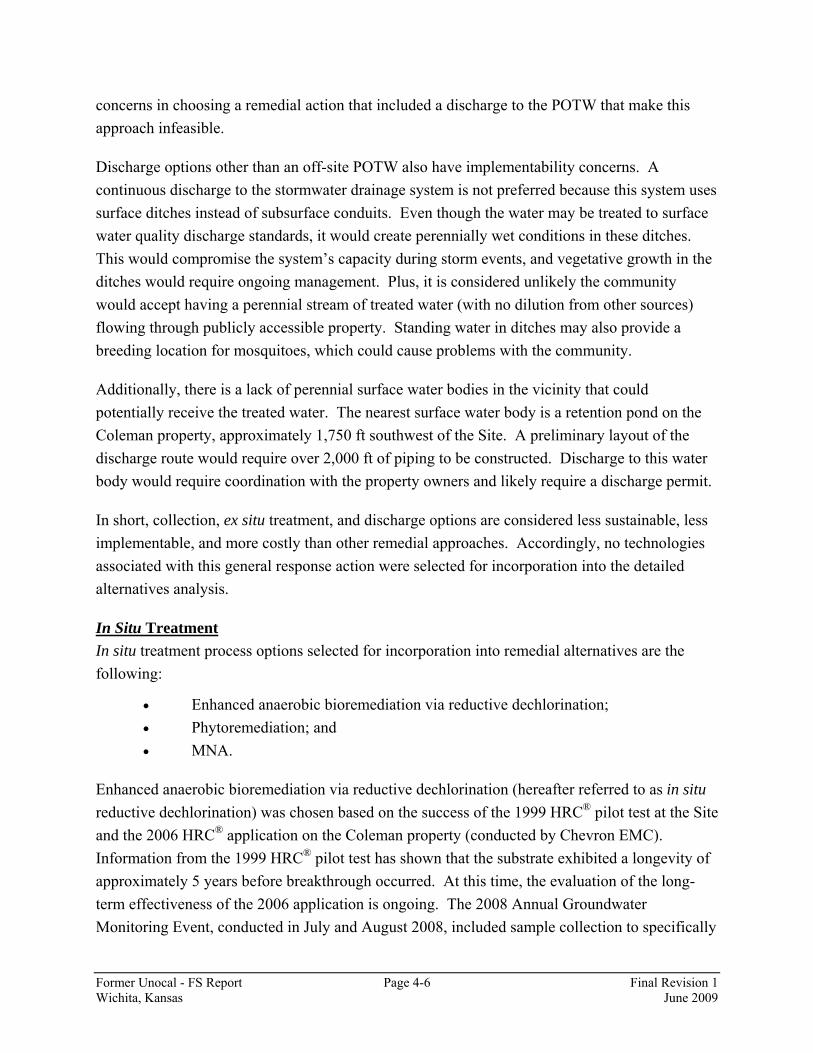
Former Unocal - FS Report Page 4-6 Final Revision 1 Wichita, Kansas June 2009
concerns in choosing a remedial action that included a discharge to the POTW that make this approach infeasible.
Discharge options other than an off-site POTW also have implementability concerns. A continuous discharge to the stormwater drainage system is not preferred because this system uses surface ditches instead of subsurface conduits. Even though the water may be treated to surface water quality discharge standards, it would create perennially wet conditions in these ditches. This would compromise the system’s capacity during storm events, and vegetative growth in the ditches would require ongoing management. Plus, it is considered unlikely the community would accept having a perennial stream of treated water (with no dilution from other sources) flowing through publicly accessible property. Standing water in ditches may also provide a breeding location for mosquitoes, which could cause problems with the community.
Additionally, there is a lack of perennial surface water bodies in the vicinity that could potentially receive the treated water. The nearest surface water body is a retention pond on the Coleman property, approximately 1,750 ft southwest of the Site. A preliminary layout of the discharge route would require over 2,000 ft of piping to be constructed. Discharge to this water body would require coordination with the property owners and likely require a discharge permit.
In short, collection, ex situ treatment, and discharge options are considered less sustainable, less implementable, and more costly than other remedial approaches. Accordingly, no technologies associated with this general response action were selected for incorporation into the detailed alternatives analysis.
In Situ Treatment In situ treatment process options selected for incorporation into remedial alternatives are the following:
• Enhanced anaerobic bioremediation via reductive dechlorination; • Phytoremediation; and • MNA.
Enhanced anaerobic bioremediation via reductive dechlorination (hereafter referred to as in situ reductive dechlorination) was chosen based on the success of the 1999 HRC® pilot test at the Site and the 2006 HRC® application on the Coleman property (conducted by Chevron EMC). Information from the 1999 HRC® pilot test has shown that the substrate exhibited a longevity of approximately 5 years before breakthrough occurred. At this time, the evaluation of the long-term effectiveness of the 2006 application is ongoing. The 2008 Annual Groundwater Monitoring Event, conducted in July and August 2008, included sample collection to specifically
Former Unocal - FS Report Page 4-7 Final Revision 1 Wichita, Kansas June 2009
evaluate the effectiveness of HRC® and CAP18-ME™. The Enhanced Reductive Dechlorination Pilot Test Results Report for the 2006 Pilot Test will be submitted to KDHE in December 2008.
Phytoremediation refers to all physical, chemical, and biological processes that are influenced by plants and their rhizospheres. In addition to providing a physical barrier, as discussed previously under Containment, a grove of trees would extract contaminated groundwater from the subsurface, a process known as phytoextraction. Once inside the plant, the contaminants may be stored, mineralized by the plants, or transpired with water vapor through the leaves. Contaminants may also be degraded in the soil or groundwater near the roots through enhanced rhizosphere degradation. Lastly, the plants may exude compounds which immobilize or stabilize the contaminants at the root-soil interface. Therefore, in addition to providing hydraulic control, phytoremediation would reduce the volume of contaminant mass in the subsurface.
Natural attenuation processes at the site were demonstrated via the 2005 Annual Groundwater Monitoring Event. During this event, a suite of parameters was analyzed to evaluate natural attenuation. These processes were clearly responsible for contaminant concentration reductions over time in Plumelets B and C. Remedial alternatives for these plumelets may rely on MNA in conjunction with another technology. Plumelets B and C are in close proximity with “off-site” Plumelets D, E, and F. The question persists whether there is a connection between the on-site and off-site plumelets. A connection has not been found with either the MIP investigation or the detailed DPT study. If a connection does exist, then addressing the source areas in Plumelets B and C would positively affect Plumelets D, E, and F.
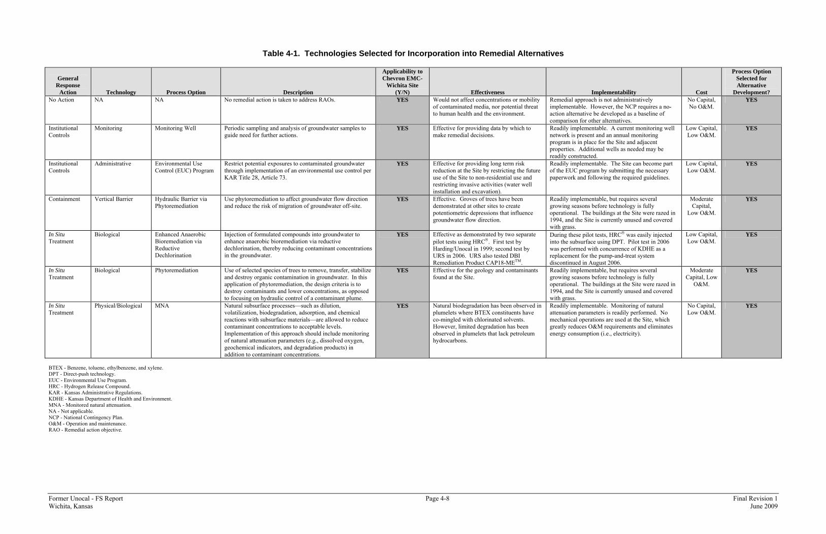
Former Unocal - FS Report Page 4-8 Final Revision 1 Wichita, Kansas June 2009
Table 4-1. Technologies Selected for Incorporation into Remedial Alternatives
General Response
Action Technology Process Option Description
Applicability to Chevron EMC-
Wichita Site (Y/N) Effectiveness Implementability Cost
Process Option Selected for Alternative
Development? No Action NA NA No remedial action is taken to address RAOs. YES Would not affect concentrations or mobility
of contaminated media, nor potential threat to human health and the environment.
Remedial approach is not administratively implementable. However, the NCP requires a no-action alternative be developed as a baseline of comparison for other alternatives.
No Capital, No O&M.
YES
Institutional Controls
Monitoring Monitoring Well Periodic sampling and analysis of groundwater samples to guide need for further actions.
YES Effective for providing data by which to make remedial decisions.
Readily implementable. A current monitoring well network is present and an annual monitoring program is in place for the Site and adjacent properties. Additional wells as needed may be readily constructed.
Low Capital, Low O&M.
YES
Institutional Controls
Administrative Environmental Use Control (EUC) Program
Restrict potential exposures to contaminated groundwater through implementation of an environmental use control per KAR Title 28, Article 73.
YES Effective for providing long term risk reduction at the Site by restricting the future use of the Site to non-residential use and restricting invasive activities (water well installation and excavation).
Readily implementable. The Site can become part of the EUC program by submitting the necessary paperwork and following the required guidelines.
Low Capital, Low O&M.
YES
Containment Vertical Barrier Hydraulic Barrier via Phytoremediation
Use phytoremediation to affect groundwater flow direction and reduce the risk of migration of groundwater off-site.
YES Effective. Groves of trees have been demonstrated at other sites to create potentiometric depressions that influence groundwater flow direction.
Readily implementable, but requires several growing seasons before technology is fully operational. The buildings at the Site were razed in 1994, and the Site is currently unused and covered with grass.
Moderate Capital,
Low O&M.
YES
In Situ Treatment
Biological Enhanced Anaerobic Bioremediation via Reductive Dechlorination
Injection of formulated compounds into groundwater to enhance anaerobic bioremediation via reductive dechlorination, thereby reducing contaminant concentrations in the groundwater.
YES Effective as demonstrated by two separate pilot tests using HRC®. First test by Harding/Unocal in 1999; second test by URS in 2006. URS also tested DBI Remediation Product CAP18-METM.
During these pilot tests, HRC® was easily injected into the subsurface using DPT. Pilot test in 2006 was performed with concurrence of KDHE as a replacement for the pump-and-treat system discontinued in August 2006.
Low Capital, Low O&M.
YES
In Situ Treatment
Biological Phytoremediation Use of selected species of trees to remove, transfer, stabilize and destroy organic contamination in groundwater. In this application of phytoremediation, the design criteria is to destroy contaminants and lower concentrations, as opposed to focusing on hydraulic control of a contaminant plume.
YES Effective for the geology and contaminants found at the Site.
Readily implementable, but requires several growing seasons before technology is fully operational. The buildings at the Site were razed in 1994, and the Site is currently unused and covered with grass.
Moderate Capital, Low
O&M.
YES
In Situ Treatment
Physical/Biological MNA Natural subsurface processes—such as dilution, volatilization, biodegradation, adsorption, and chemical reactions with subsurface materials—are allowed to reduce contaminant concentrations to acceptable levels. Implementation of this approach should include monitoring of natural attenuation parameters (e.g., dissolved oxygen, geochemical indicators, and degradation products) in addition to contaminant concentrations.
YES Natural biodegradation has been observed in plumelets where BTEX constituents have co-mingled with chlorinated solvents. However, limited degradation has been observed in plumelets that lack petroleum hydrocarbons.
Readily implementable. Monitoring of natural attenuation parameters is readily performed. No mechanical operations are used at the Site, which greatly reduces O&M requirements and eliminates energy consumption (i.e., electricity).
No Capital, Low O&M.
YES
BTEX - Benzene, toluene, ethylbenzene, and xylene. DPT - Direct-push technology. EUC - Environmental Use Program. HRC - Hydrogen Release Compound. KAR - Kansas Administrative Regulations. KDHE - Kansas Department of Health and Environment. MNA - Monitored natural attenuation. NA - Not applicable. NCP - National Contingency Plan. O&M - Operation and maintenance. RAO - Remedial action objective.
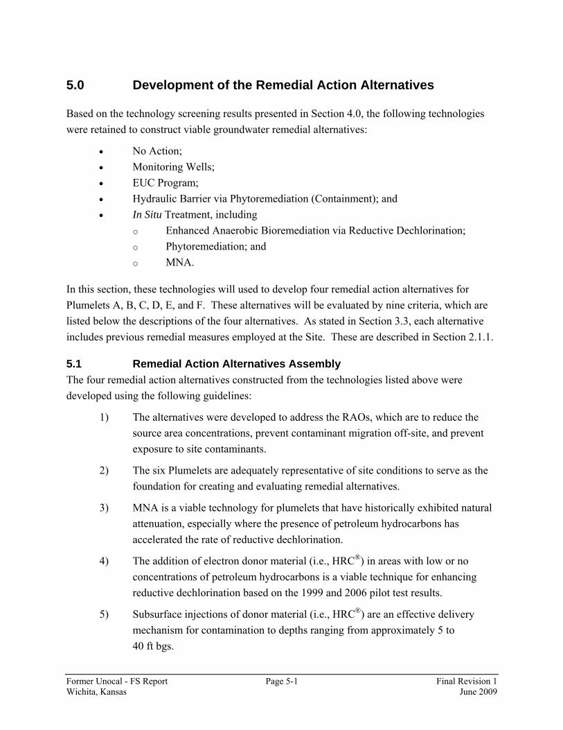
Former Unocal - FS Report Page 5-1 Final Revision 1 Wichita, Kansas June 2009
5.0 Development of the Remedial Action Alternatives
Based on the technology screening results presented in Section 4.0, the following technologies were retained to construct viable groundwater remedial alternatives:
• No Action; • Monitoring Wells; • EUC Program; • Hydraulic Barrier via Phytoremediation (Containment); and • In Situ Treatment, including
o Enhanced Anaerobic Bioremediation via Reductive Dechlorination; o Phytoremediation; and o MNA.
In this section, these technologies will used to develop four remedial action alternatives for Plumelets A, B, C, D, E, and F. These alternatives will be evaluated by nine criteria, which are listed below the descriptions of the four alternatives. As stated in Section 3.3, each alternative includes previous remedial measures employed at the Site. These are described in Section 2.1.1.
5.1 Remedial Action Alternatives Assembly The four remedial action alternatives constructed from the technologies listed above were developed using the following guidelines:
1) The alternatives were developed to address the RAOs, which are to reduce the source area concentrations, prevent contaminant migration off-site, and prevent exposure to site contaminants.
2) The six Plumelets are adequately representative of site conditions to serve as the foundation for creating and evaluating remedial alternatives.
3) MNA is a viable technology for plumelets that have historically exhibited natural attenuation, especially where the presence of petroleum hydrocarbons has accelerated the rate of reductive dechlorination.
4) The addition of electron donor material (i.e., HRC®) in areas with low or no concentrations of petroleum hydrocarbons is a viable technique for enhancing reductive dechlorination based on the 1999 and 2006 pilot test results.
5) Subsurface injections of donor material (i.e., HRC®) are an effective delivery mechanism for contamination to depths ranging from approximately 5 to 40 ft bgs.

Former Unocal - FS Report Page 5-2 Final Revision 1 Wichita, Kansas June 2009
6) Phytoremediation is not considered a viable technology to address contamination deeper than 25 ft bgs.
7) Phytoremediation does not provide complete hydraulic control during the growth period (5 to 7 years).
Technologies retained from Section 4.0 were combined into different remedial action alternatives based on the collective physical and chemical characteristics of the source areas. These alternatives will be evaluated on a site-wide basis rather than on a Plumelet basis.
Four remedial action alternatives were developed for the on-site groundwater:
• Alternative 1: No Action; • Alternative 2: MNA and the EUC Program; • Alternative 3: Enhanced Reductive Dechlorination; and, • Alternative 4: Enhanced Reductive Dechlorination and Phytoremediation.
5.2 Descriptions of the Remedial Action Alternatives Each of the alternative descriptions below address how the alternative would be applied to historical Plumelets A, B, C, D, E and F.
5.2.1 Alternative 1: No Action The no action alternative provides a baseline for comparison for the other three alternatives. Alternative 1 would provide long-term monitoring (LTM) of Site groundwater, but no further actions would be taken to reduce contaminant mass, address potential exposure pathways, or reduce the potential for off-site migration. For this alternatives analysis, the monitoring wells included in the LTM program for Alternative 1 are a subset of those listed in the Final Revision 2 Sampling and Analysis Plan (URS, July 2008). This subset of wells, shown on Figure 5-1, is located on the Site proper and immediately adjacent to the Site. Samples from these wells would be collected annually for thirty years and analyzed for the target VOCs listed in the Final Revision 2 Sampling and Analysis Plan (URS, July 2008).
5.2.2 Alternative 2: Monitored Natural Attenuation and Environmental Use Control Program
Under this alternative, KDHE’s EUC program would be utilized to limit potential human exposure to Site contaminants. Exposure pathways to be limited are those identified in the site-specific RAOs presented in Section 3.3 (i.e., residential exposure to groundwater via ingestion, inhalation, and dermal contact).

Former Unocal - FS Report Page 5-3 Final Revision 1 Wichita, Kansas June 2009
The LTM program described in Alternative 1 would be expanded by analyzing groundwater samples for parameters associated with natural attenuation (e.g., alkalinity, chloride, ethane, ethene, and methane) to help determine whether biodegradation is occurring. A one-time evaluation may also be performed to determine additional natural attenuation parameters, such as phosphorus, potassium, total organic carbon, and dehalococluides sp. bacteria. Field parameters, including dissolved oxygen, oxidation reduction potential (ORP), and conductivity, would also be evaluated. An MNA program at the Site would consist of collecting samples from the wells included in Alternative 1, as well as ten additional wells (four proposed and six existing wells), within the Site and the vicinity (as shown on Figure 5-2). MNA data would be used to quantify natural attenuation processes on an annual basis to determine whether remediation was satisfactorily occurring to address the RAOs. MNA would be evaluated on a yearly basis in accordance with the Technical Protocol for Evaluating Natural Attenuation of Chlorinated Solvents in Ground Water (EPA, 1998).
Implementation of Alternative 2 would be subject to the Bureau of Environmental Remediation Policy # BER-RS-042, which requires demonstration of seven “Criteria for Determining when MNA may be Appropriate:”
1) Threat to Human Health 2) Degradation of Ground Water 3) Degradation of Surface Water 4) Threat to Other Potential Receptors 5) Time Frame and Cost 6) Property Control 7) Resource Management
If the selected alternative consists of a natural attenuation component, these criteria will be evaluated and documented during the Proposed Plan/Remedial Design Phases of implementation.
Additionally, Plumelets D, E, and F (off-site) have remained relatively stable in terms of contaminant extent in recent years, with concentrations of most chlorinated constituents decreasing. These Plumelets will be subjected to MNA and will be monitored annually for five years. After five years, a review will be performed to evaluate the effectiveness of MNA for those plumelets.
5.2.3 Alternative 3: Enhanced Reductive Dechlorination This alternative combines the technologies presented in Alternative 2 (MNA and EUC Program) with the implementation of enhanced reductive dechlorination in specific areas through the

Former Unocal - FS Report Page 5-4 Final Revision 1 Wichita, Kansas June 2009
injection of electron donor material (i.e., HRC®). These injections would be used to reduce source contaminant mass and to create biobarriers to reduce the potential migration off-site at concentrations above the RSK Tier 2 residential standards. Previous injections of HRC® at the Site, conducted south of P-5 in historical Plumelet A, decreased chlorinated solvent concentrations to below or near the RSK Tier 2 residential standards within a relatively short time. Additionally, on the basis of the 1999 pilot test, the reduced concentrations last for at least five years before reinjection is required. While HRC® has been previously tested at the site, a variety of electron donor material will be evaluated for injection prior to implementation of this alternative.
For historical Plumelet A, both source reduction and biobarriers would be used for this alternative (Figure 5-3). A biobarrier would be used along the fence line with corresponding source reduction injections (i.e., two injection rows) within the plume. The injections directly over the source area and in the downgradient biobarrier would extend across the saturated zone (9 to 40 ft bgs). Based on the MIP results near P-2 (MIP-18), the injections near the 1999 pilot test injections would extend over the lower portion of the saturated zone that contains a large portion of the contaminant mass (22 to 30 ft bgs). It is anticipated that these injections may need to be reapplied at least once five years after the initial injection; however, the cumulative volume of HRC® injected would be lower for the subsequent injection. Monitoring wells P-11 and P-12 are proposed for installation upgradient of the source area injection and adjacent to the fence line, respectively, to assist in monitoring the effect of the injections. Both of these wells would be screened across the entire saturated zone (9 to 40 ft bgs). Based on the calculation presented in Appendix D, it is anticipated that three injections may occur over a ten year period (Initial injection, Year 5 reinjection and Year 10 reinjection).
Historical Plumelet B contains lower concentrations of BTEX relative to the concentrations of chlorinated solvents in the source area. For this plumelet, injections of HRC® (i.e., two injection rows) in the source zone are proposed to complete the dechlorination process (Figure 5-4). Based on the MIP results for MIP-27 and MIP-29, these injection rows will extend from 15 to 30 ft bgs; however, the use and design of these injection rows will be evaluated based on the sample results from proposed monitor well MW-27. Since Plumelet B is relatively long, a biobarrier is proposed along the Site’s southern fence line (Figure 5-4). The use and design of this biobarrier will be evaluated based on the sample results from proposed monitor well MW-17S.
Monitoring wells MW-17S and MW-27 are proposed for installation upgradient of the source area injection and adjacent to the fenceline and the current well MW-17, respectively, to assist in monitoring the effect of the injections. If warranted, this fence line injection will be reapplied after five years to further address potential migration of contaminants off-site. Based on the

Former Unocal - FS Report Page 5-5 Final Revision 1 Wichita, Kansas June 2009
calculation presented in Appendix D, it is anticipated that two injections in the source area and along the fenceline may occur over a five year period (Initial injection and Year 5 reinjection).
Since petroleum hydrocarbons, especially toluene, are present at high concentrations in the source area for historical Plumelet C (based on the MIP results), HRC® injections are not expected to be necessary within the actual source area (MIP-15). However, to address potential migration issues, an HRC® biobarrier is proposed for installation along the southern and western extents of historical Plumelet C (Figure 5-5). Based on the MIP results for that area, HRC® would be injected from 6 to 18 ft bgs. Based on the longevity of the 1999 pilot test, these biobarriers may be reinjected after five years to further address potential migration of contaminants off-site. Based on the calculations presented in Appendix D, it is anticipated that three injections may occur over a ten year period (Initial injection, Year 5 reinjection and Year 10 reinjection). In addition to the proposed monitoring well MW-28, the on-site well MW-4 and the off-site USD wells USD-1, USD-2, USD-3 and Pinsker well PMW-7 would be used to monitor these barriers (Figure 5-2).
Plumelets D, E, and F (off-site) have remained relatively stable in terms of contaminant extent in recent years, with concentrations of chlorinated constituents decreasing. These Plumelets will be subjected to MNA for this alternative and will be monitored annually for five years. After five years, a review will be performed to evaluate the effectiveness of MNA for those plumelets. If results from the annual events or the five year review indicate that the plumelets are expanding, an active remedial measure (i.e. enhanced reductive dechlorination) will be implemented to prevent further migration and to reduce areas with concentrations of COCs significantly above the RSK Tier 2 residential standards (as necessary). A summary of the technologies proposed in Alternative 3 for the various plumelets is shown on Figure 5-6.
5.2.4 Alternative 4: Enhanced Reductive Dechlorination and Phytoremediation
This alternative is a modification of Alternative 3, with the use of phytoremediation for both hydraulic control and contaminant uptake. Deep-rooted willows have been shown to provide hydraulic control to depths of 25 ft bgs (see Appendix C), as well as enhance biodegradation of BTEX and chlorinated solvents in the root system (rhizosphere). Contaminants are also subjected to “uptake” through the trees, distributed to the leaves, and then photovolatilized in the atmosphere.
The willow stands would consist of rows of trees that are oriented perpendicular to the direction of groundwater flow (Figure 5-7). The trees would be planted on 10 ft centers (10 ft between the rows, and 10 ft between trees within a row). The rate of groundwater uptake by the tree stand
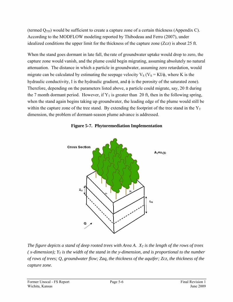
Former Unocal - FS Report Page 5-6 Final Revision 1 Wichita, Kansas June 2009
(termed QTD) would be sufficient to create a capture zone of a certain thickness (Appendix C). According to the MODFLOW modeling reported by Thibodeau and Ferro (2007), under idealized conditions the upper limit for the thickness of the capture zone (Zcz) is about 25 ft.
When the stand goes dormant in late fall, the rate of groundwater uptake would drop to zero, the capture zone would vanish, and the plume could begin migrating, assuming absolutely no natural attenuation. The distance in which a particle in groundwater, assuming zero retardation, would migrate can be calculated by estimating the seepage velocity VS (VS = KI/φ, where K is the hydraulic conductivity, I is the hydraulic gradient, and φ is the porosity of the saturated zone). Therefore, depending on the parameters listed above, a particle could migrate, say, 20 ft during the 7 month dormant period. However, if YT is greater than 20 ft, then in the following spring, when the stand again begins taking up groundwater, the leading edge of the plume would still be within the capture zone of the tree stand. By extending the footprint of the tree stand in the YT dimension, the problem of dormant-season plume advance is addressed.
Figure 5-7. Phytoremediation Implementation
The figure depicts a stand of deep rooted trees with Area A. XT is the length of the rows of trees ( x-dimension); YT is the width of the stand in the y-dimension, and is proportional to the number of rows of trees; Q, groundwater flow; Zaq, the thickness of the aquifer; Zcz, the thickness of the capture zone.
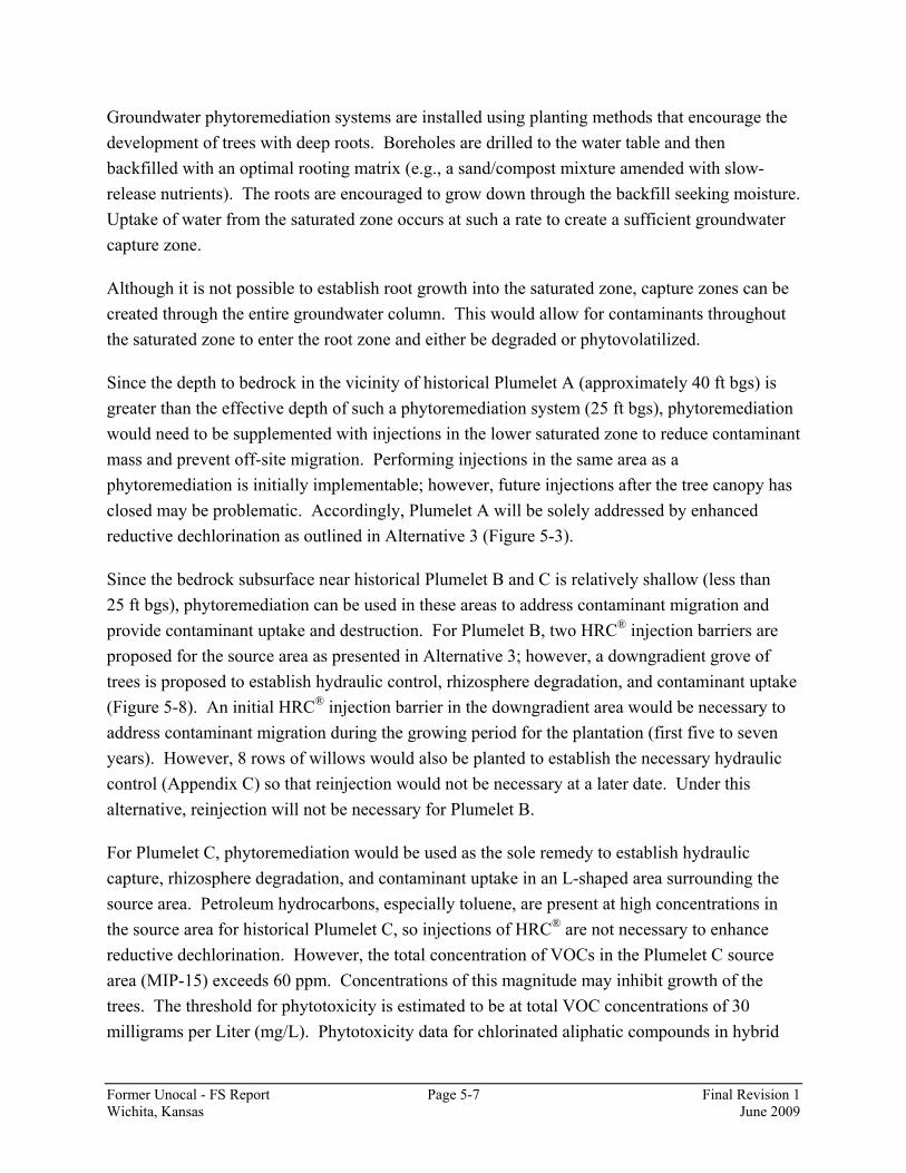
Former Unocal - FS Report Page 5-7 Final Revision 1 Wichita, Kansas June 2009
Groundwater phytoremediation systems are installed using planting methods that encourage the development of trees with deep roots. Boreholes are drilled to the water table and then backfilled with an optimal rooting matrix (e.g., a sand/compost mixture amended with slow-release nutrients). The roots are encouraged to grow down through the backfill seeking moisture. Uptake of water from the saturated zone occurs at such a rate to create a sufficient groundwater capture zone.
Although it is not possible to establish root growth into the saturated zone, capture zones can be created through the entire groundwater column. This would allow for contaminants throughout the saturated zone to enter the root zone and either be degraded or phytovolatilized.
Since the depth to bedrock in the vicinity of historical Plumelet A (approximately 40 ft bgs) is greater than the effective depth of such a phytoremediation system (25 ft bgs), phytoremediation would need to be supplemented with injections in the lower saturated zone to reduce contaminant mass and prevent off-site migration. Performing injections in the same area as a phytoremediation is initially implementable; however, future injections after the tree canopy has closed may be problematic. Accordingly, Plumelet A will be solely addressed by enhanced reductive dechlorination as outlined in Alternative 3 (Figure 5-3).
Since the bedrock subsurface near historical Plumelet B and C is relatively shallow (less than 25 ft bgs), phytoremediation can be used in these areas to address contaminant migration and provide contaminant uptake and destruction. For Plumelet B, two HRC® injection barriers are proposed for the source area as presented in Alternative 3; however, a downgradient grove of trees is proposed to establish hydraulic control, rhizosphere degradation, and contaminant uptake (Figure 5-8). An initial HRC® injection barrier in the downgradient area would be necessary to address contaminant migration during the growing period for the plantation (first five to seven years). However, 8 rows of willows would also be planted to establish the necessary hydraulic control (Appendix C) so that reinjection would not be necessary at a later date. Under this alternative, reinjection will not be necessary for Plumelet B.
For Plumelet C, phytoremediation would be used as the sole remedy to establish hydraulic capture, rhizosphere degradation, and contaminant uptake in an L-shaped area surrounding the source area. Petroleum hydrocarbons, especially toluene, are present at high concentrations in the source area for historical Plumelet C, so injections of HRC® are not necessary to enhance reductive dechlorination. However, the total concentration of VOCs in the Plumelet C source area (MIP-15) exceeds 60 ppm. Concentrations of this magnitude may inhibit growth of the trees. The threshold for phytotoxicity is estimated to be at total VOC concentrations of 30 milligrams per Liter (mg/L). Phytotoxicity data for chlorinated aliphatic compounds in hybrid

Former Unocal - FS Report Page 5-8 Final Revision 1 Wichita, Kansas June 2009
poplar trees come from reports by Newman et al. (1997), and Ferro et al. (1999). Because both willows and poplars are in the same family (Salicaceae), it is expected that the tolerance would be similar for the two groups. Ferro et al. (1999) exposed hybrid poplars to a mixture of volatile organic compounds, including DCE (25 mg/L), trichloroethane (25 mg/L) and dichloroethane (25 mg/L). The mixture of VOCs also contained certain non-chlorinated compounds, including ethylbenzene, xylenes, toluene, and butanol (total concentration, 170 mg VOCs/L). The report concluded that phytotoxic effects were not observed based on evaluations of stomatal conductance, shoot elongation and biomass production, including root development.
Accordingly, the grove of trees will be planted further downgradient of the highest concentrations to address migration, while allowing the trees to be established in a zone of lower VOC concentrations. Figure 5-9 shows the area to be planted under this alternative. At this location, the highest total concentration of chlorinated VOCs to which the trees would be exposed is ~ 1 mg/L for the trees planted within Plumelet C, which is far below the threshold for phytotoxicity. In addition to the proposed monitoring well MW-28, the on-site well MW-4 and the off-site USD wells USD-1, USD-2, and USD-3 and Pinsker well PMW-7 would be used to monitor the phytoremedial activities (Figure 5-2).
If phytoremediation is shown to be ineffective or inadequate for Plumelets B and C, as a contingency after implementation, the remedial actions described in Alternative 3 will be implemented to prevent further migration and/or to reduce concentrations of COCs in the source areas.
Plumelets D, E, and F have remained relatively stable in terms of contaminant extent in recent years, with concentrations of chlorinated constituents decreasing. As with Alternative 3, these Plumelets will be subjected to MNA in this alternative, and will be monitored annually for five years. After five years, a review will be performed to evaluate the effectiveness of MNA for those plumelets. If results from the annual events or the five year review indicate that the plumelets are expanding, an active remedial measure (i.e. enhanced reductive dechlorination) will be implemented to prevent further migration and to reduce areas with concentrations of COCs significantly above the RSK Tier 2 residential standards (as necessary). A summary of the technologies proposed in Alternative 4 for the various plumelets is shown on Figure 5-10.
5.3 Evaluation Criteria The detailed analysis of alternatives is based on the nine evaluation criteria specified in the NCP [40 CFR Section 300.430(e)(9)(iii)] and the Guidance for Conducting Remedial Investigations and Feasibility Studies Under CERCLA (EPA, October 1988). The criteria include the following:

Former Unocal - FS Report Page 5-9 Final Revision 1 Wichita, Kansas June 2009
1. Overall protection of human health and environment; 2. Compliance with applicable or relevant and appropriate requirements (ARARs); 3. Long-term effectiveness and permanence; 4. Reduction of toxicity, mobility, or volume through treatment; 5. Short-term effectiveness; 6. Implementability; 7. Cost; 8. State acceptance; and 9. Community acceptance.
These evaluation criteria are divided into three categories: threshold, primary balancing, and modifying criteria. Threshold criteria (Nos. 1 and 2) are those that must be met for an alternative to be viable for selection in the Record of Decision (ROD). Accordingly, as part of the evaluation, a “Yes” or “No” is provided to indicate whether the alternative is available for selection in the ROD.
Primary balancing criteria (Nos. 3 through 7) form the basis for comparing alternatives. To facilitate the evaluation, each alternative’s performance with regard to the criterion is assigned one of the following rankings:
• Excellent. Alternative is expected to have high performance on most, if not all, of the considerations specific to the criterion.
• Good. Alternative is expected to perform well on most of the considerations specific to the criterion, with no significant concerns.
• Fair. Alternative has one or more significant concerns specific to the criterion, but concerns can be adequately addressed through proper planning, design, and implementation.
• Poor. Alternative has substantial concerns for one or more considerations specific to criterion that may not meet minimum performance standards.
The rankings are assigned according to best professional judgment and are used only as a means of weighing tradeoffs in the various factors considered for each criterion. A ranking is not assigned to cost since it may be readily quantified and does not warrant a qualitative rating. Costs are evaluated in terms of net present value dollars.
Modifying criteria (Nos. 8 and 9) consider state and community acceptance. As specified in Guidance for Conducting Remedial Investigations and Feasibility Studies Under CERCLA (EPA, October 1988) and the NCP [40 CFR 300.430(e)(9)(H)-(I)], the modifying criteria are

Former Unocal - FS Report Page 5-10 Final Revision 1 Wichita, Kansas June 2009
addressed in the ROD after the RI, FS, and Proposed Plan have been completed, incorporating state and community feedback. As such, modifying criteria are not evaluated in this FS Report.

!A
!A
!A
!A
!A!A
!A
!A!A
!A
!A
!A
!A
!A
!A !A !A
!A
!A!A!A!A
!A
!A
!A
!A!A!A
!A
!A
!A
!A
HistoricalPlumelet A -
PCE and1,1,1-TCA
HistoricalPlumelet B -
PCE and BTEX
HistoricalPlumelet D -
PCE and BTEX
HistoricalPlumelet C -
VariousConstituents
HistoricalPlumelet E -
PCE
HistoricalPlumelet F -
Primarily TCE
PMW-8
TW-2A
Trailer
MW-13
MW-24
USD-3
USD-2
USD-1
TW-3TW-1
R-1
PMW-5
PMW-4
P-9P-8
P-7 P-6P-5
P-2P-10
P-1
MW-6
MW-5
MW-4
USD-MW-3
MW-2
MW-1S
MW-1D
MW-17
USD-MW-16USD-MW-14
USD-4
PMW-7
37TH ST
Former Unocal Chemical Distribution FacilityWichita, Kansas
9400 Amberglen Blvd.Austin, TX 78729Phone: (512) 454-4797Fax: (512) 419-5474
Client:
Drawn by: Date: GIS File: Figure:5-1GWC/AUS
Figure 5-1Alternative 1
Long-Term GroundwaterMonitoring Locations
µ120 0 12060
Feet
LegendFormer Unocal Site Boundary
Building
Road (Paved)
Road (Unpaved)
X Fence Line
Railroad Track
Stormwater Drainage Ditch
Historical Plumelet
Groundwater Flow Direction
!AGroundwater Elevation Measuredfor Long-Term Monitoring
!AGroundwater Elevation Measuredand Sample Taken for Long-Term Monitoring
= Piezometer= Monitoring Well on Unocal or Coleman Property (D = Deep, S = Shallow)= Monitoring Well on USD Property= Monitoring Well on Pinsker Property= Recovery Well (Not Pumping During 2005 Event)= Test Well= Monitoring Well on USD Property Installed by Unocal
PZ or PMW
USDPMW
R
TWUSD-MW
Abbreviations
Note:The wells in the Long-Term Monitoring program arethe same wells listed in the Final Revision 2 Samplingand Analysis Plan (July 2008).
Q:\U
noca
l-Wich
ita\D
rawing
s\FS_
Repo
rt\20
09_M
arch\F
ig 5-1
Alt01
.mxd
6/24
/2009
@ 10
:25:40
AM
Fig 5-1 Alt01.mxd 6/24/2009

!A
!A
!A
!A!A
!A
!A
!A
!A!A!A
!A
!A!A
!A
!A
!A
!A
!A
!A !A !A
!A
!A!A!A!A
!A
!A
!A
!A!A!A
!A
!A
!A
!A
!A
!A
!A
!A
!A
!A
HistoricalPlumelet A -
PCE and1,1,1-TCA
HistoricalPlumelet B -
PCE and BTEX
HistoricalPlumelet D -
PCE and BTEX
HistoricalPlumelet C -
VariousConstituents
HistoricalPlumelet E -
PCE
HistoricalPlumelet F -
Primarily TCE
TW-2A
PMW-8
Trailer
MW-24
USD-3
USD-2
USD-1
TW-3TW-1
R-1
PMW-5
PMW-4
P-9P-8
P-7 P-6P-5
P-2P-10
P-1
MW-6
MW-5
MW-4
USD-MW-3
MW-2
MW-1S
MW-1D
MW-17
USD-MW-16USD-MW-14
USD-4
PMW-7
37TH ST
MW-28
MW-26 MW-27
MW-17S
P-12
P-11
Former Unocal Chemical Distribution FacilityWichita, Kansas
9400 Amberglen Blvd.Austin, TX 78729Phone: (512) 454-4797Fax: (512) 419-5474
Client:
Drawn by: Date: GIS File: Figure:5-2GWC/AUS
Figure 5-2Alternative 2
MNA and Long-TermGroundwater Monitoring Locations
µ120 0 12060
Feet
LegendFormer Unocal Site Boundary
Building
Road (Paved)
Road (Unpaved)
X Fence Line
Railroad Track
Stormwater Drainage Ditch
Historical Plumelet
Groundwater Flow Direction
!AGroundwater Elevation Measuredfor Long-Term Monitoring
!AGroundwater Elevation Measuredand Sample Taken for Long-Term Monitoring
!AGroundwater Elevation Measuredand Sample Taken for MNA Monitoring
!AProposed Monitoring Well LocationGroundwater Elevation Measuredand Sample Taken for MNA Monitoring
Fig 5-2 Alt02.mxd 6/24/2009
= Piezometer= Monitoring Well on Unocal or Coleman Property (D = Deep, S = Shallow)= Monitoring Well on USD Property= Monitoring Well on Pinsker Property= Recovery Well (Not Pumping During 2005 Event)= Test Well= Monitoring Well on USD Property Installed by Unocal
PZ or PMW
USDPMW
R
TWUSD-MW
Abbreviations
Note:The wells in the Long-Term Monitoring program arethe same wells listed in the Final Revision 2 Samplingand Analysis Plan (July 2008).
Q:\U
noca
l-Wich
ita\D
rawing
s\FS_
Repo
rt\20
09_M
arch\F
ig 5-2
Alt02
.mxd
6/24
/2009
@ 10
:26:03
AM
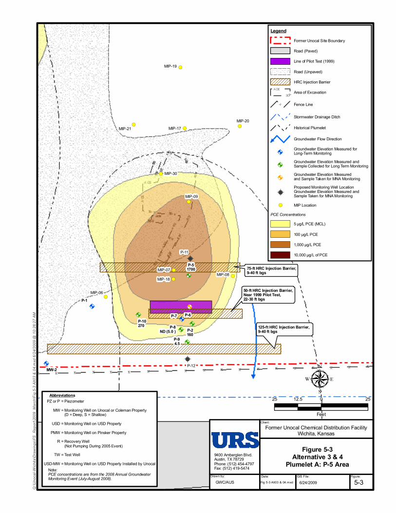
!A
!A
!A
!A
!A
!A
!A
!A
!A
!A
!A
!A
!A
!A
!(
!(
!(
!(
!(
!(
!(
!(!(
!(
!(
125-ft HRC Injection Barrier, 9-40 ft bgs
50-ft HRC Injection Barrier,Near 1999 Pilot Test,22-30 ft bgs
75-ft HRC Injection Barrier,9-40 ft bgs
MIP-30
MIP-21MIP-20
MIP-18
MIP-19
MIP-17
MIP-09
MIP-06
MIP-07MIP-08
P-12
P-11
P-94.5
P-8ND (5.0 )
P-7 P-6
P-51700
P-2160
P-10270
P-1
MW-2
MW-1S
MW-1D
Former Unocal Chemical Distribution FacilityWichita, Kansas
9400 Amberglen Blvd.Austin, TX 78729Phone: (512) 454-4797Fax: (512) 419-5474
Client:
Drawn by: Date: GIS File: Figure:5-3GWC/AUS
Figure 5-3Alternative 3 & 4
Plumelet A: P-5 Area
Fig 5-3 Alt03 & 04.mxd 6/24/2009
= Piezometer= Monitoring Well on Unocal or Coleman Property (D = Deep, S = Shallow)= Monitoring Well on USD Property= Monitoring Well on Pinsker Property= Recovery Well (Not Pumping During 2005 Event)= Test Well= Monitoring Well on USD Property Installed by Unocal
PZ or PMW
USDPMW
R
TWUSD-MW
Abbreviations
Note:PCE concentrations are from the 2008 Annual GroundwaterMonitoring Event (July-August 2008).
µ25 0 2512.5
Feet
LegendFormer Unocal Site Boundary
Road (Paved)
Line of Pilot Test (1999)
Road (Unpaved)
HRC Injection BarrierA
A
O
O
E
E Area of Excavation
X Fence Line
Stormwater Drainage Ditch
Historical Plumelet
Groundwater Flow Direction
!AGroundwater Elevation Measured forLong-Term Monitoring
!AGroundwater Elevation Measured andSample Collected for Long Term Monitoring
!AGroundwater Elevation Measuredand Sample Taken for MNA Monitoring
!AProposed Monitoring Well LocationGroundwater Elevation Measured andSample Taken for MNA Monitoring
!( MIP LocationPCE Concentrations
5 µg/L PCE (MCL)
100 µg/L PCE
1,000 µg/L PCE
10,000 µg/L of PCE
Q:\U
noca
l-Wich
ita\D
rawing
s\FS_
Repo
rt\20
09_M
arch\F
ig 5-3
Alt03
& 04
.mxd
6/24
/2009
@ 10
:26:27
AM

!A
!A
!A
!A
!A!A
!A!A
!A
!A
!(
!(
!(
!(
!(
!(
!(!(
!(
!(
!(
!(
!(
Two 50-ft HRC Injection Barriers,15-30 ft bgs
100-ft HRC Injection Barriers,17-27 ft bgs
MIP-30
MIP-29
MIP-28
MIP-24
MIP-23
MIP-22MIP-25
MIP-27
MIP-26
MIP-21
MIP-14
MIP-16
MIP-06
MW-27
MW-17S
R-1ND (0.1 )
P-10270
P-1
MW-6
MW-588
MW-2
MW-17
Former Unocal Chemical Distribution FacilityWichita, Kansas
9400 Amberglen Blvd.Austin, TX 78729Phone: (512) 454-4797Fax: (512) 419-5474
Client:
Drawn by: Date: GIS File: Figure:5-4GWC/AUS
Figure 5-4Alternative 3
Plumelet B: Tank Farm Area
µ30 0 3015
Feet
6/24/2009
Q:\U
noca
l-Wich
ita\D
rawing
s\FS_
Repo
rt\20
09_M
arch\F
ig 5-4
Alt03
.mxd
6/24
/2009
@ 10
:26:53
AMLegend
Former Unocal Site Boundary
Road (Paved)
Line of Pilot Test (1999)
Road (Unpaved)
HRC Injection BarrierA
A
O
O
E
E Area of Excavation
X Fence Line
Stormwater Drainage Ditch
Historical Plumelet
Groundwater Flow Direction
!AGroundwater Elevation Measured forLong-Term Monitoring
!AGroundwater Elevation Measured andSample Collected for Long-Term Monitoring
!AGroundwater Elevation Measuredand Sample Taken for MNA Monitoring
!( MIP Location
!AProposed Monitoring Well LocationGroundwater Elevation Measuredand Sample Taken for MNA Monitoring
PCE Concentrations5 µg/L PCE (MCL)
100 µg/L PCE
1,000 µg/L PCE
10,000 µg/L of PCE
= Piezometer= Monitoring Well on Unocal or Coleman Property (D = Deep, S = Shallow)= Monitoring Well on USD Property= Monitoring Well on Pinsker Property= Recovery Well (Not Pumping During 2005 Event)= Test Well= Monitoring Well on USD Property Installed by Unocal
PZ or PMW
USDPMW
R
TWUSD-MW
Abbreviations
Note:PCE concentrations are from the 2008 Annual GroundwaterMonitoring Event (July-August 2008).The use and location of injection barriers are based on thelocation of former source area and MIP-27 results.Injection barriers will be evaluated based on the sample resultsfrom MW-27 and MW-17S.
Fig 5-4 Alt03.mxd

!A
!A
!A
!A
!(
!(
!(
!(
!(
!(
!(
!(
!(
!(
!(
!(
!(
!(!(
!(
!(
!(
!(
90-ft HRC Injection Barrier,6-18 ft bgs
120-ft HRC Injection Barrier,6-18 ft bgs
Trailer
MIP-29
MIP-28
MIP-24
MIP-23
MIP-22 MIP-25
MIP-27
MIP-14
MIP-16
MIP-15
MIP-13
MIP-12
MIP-11
MIP-10
MIP-03a
MIP-04
MIP-03MIP-02
MIP-01
MW-28
MW-26
MW-27
MW-17S
9400 Amberglen Blvd.Austin, TX 78729Phone: (512) 454-4797Fax: (512) 419-5474
Drawn by: Date: GIS File: Figure:5-5GWC/AUS
Figure 5-5Alternative 3
Plumelet C: MIP-15 Area
6/24/2009
Former Unocal Chemical Distribution FacilityWichita, Kansas
µ30 0 3015
Feet
Q:\U
noca
l-Wich
ita\D
rawing
s\FS_
Repo
rt\20
09_M
arch\F
ig 5-5
Alt03
.mxd
6/24
/2009
@ 10
:27:19
AM
Client:
= Piezometer= Monitoring Well on Unocal or Coleman Property (D = Deep, S = Shallow)= Monitoring Well on USD Property= Monitoring Well on Pinsker Property= Recovery Well (Not Pumping During 2005 Event)= Test Well= Monitoring Well on USD Property Installed by Unocal
PZ or PMW
USDPMW
R
TWUSD-MW
Abbreviations
Note:PCE concentrations are from the 2008 Annual GroundwaterMonitoring Event (July-August 2008).The PCE concentration in the groundwater grab from MW-15(collected in July 2007) was 27,000 µg/L.
Fig 5-5 Alt03.mxd
LegendFormer Unocal Site Boundary
Road (Unpaved)
HRC Injection BarrierA
A
O
O
E
E Area of Excavation
X Fence Line
Historical Plumelet
Groundwater Flow Direction
!AProposed Monitoring Well LocationGroundwater Elevation Measuredand Sample Taken for MNA Monitoring
!( MIP Location
PCE Concentrations5 µg/L PCE (MCL)
100 µg/L PCE
1,000 µg/L PCE
10,000 µg/L of PCE
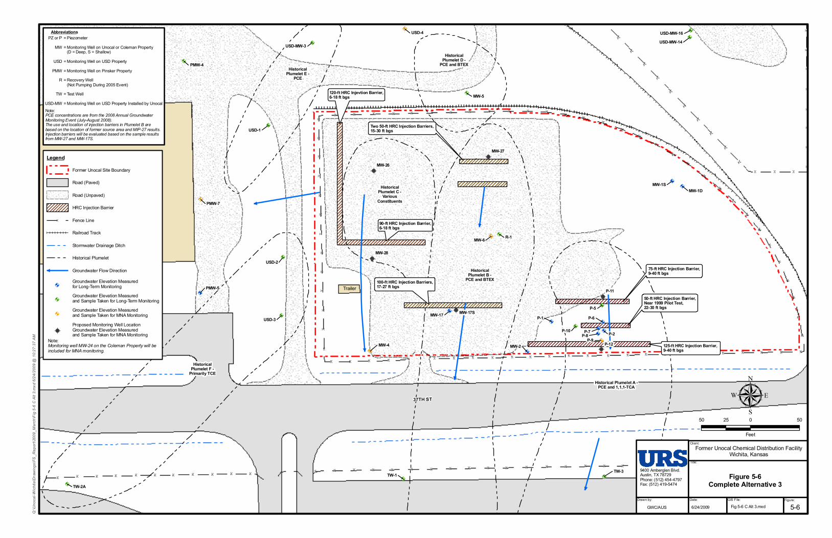
!A
!A
!A
!A
!A
!A
!A
!A
!A
!A
!A
!A
!A
!A
!A
!A
!A
!A
!A
!A!A
!A
!A
!A
!A!A
!A
!A
!A
!A
!A!A
!A
!A
!A
!A
!A
!A
!A
!A
!A
Historical Plumelet A -PCE and 1,1,1-TCA
HistoricalPlumelet B -
PCE and BTEX
HistoricalPlumelet D -
PCE and BTEX
HistoricalPlumelet C -
VariousConstituents
HistoricalPlumelet E -
PCE
HistoricalPlumelet F -
Primarily TCE
125-ft HRC Injection Barrier, 9-40 ft bgs
50-ft HRC Injection Barrier,Near 1999 Pilot Test,22-30 ft bgs
75-ft HRC Injection Barrier,9-40 ft bgs
Two 50-ft HRC Injection Barriers,15-30 ft bgs
100-ft HRC Injection Barriers,17-27 ft bgs
90-ft HRC Injection Barrier,6-18 ft bgs
120-ft HRC Injevtion Barrier,6-18 ft bgs
Trailer
USD-3
USD-2
USD-1
TW-3
TW-2A
TW-1
R-1
PMW-5
PMW-4
P-9P-8P-7
P-6P-5
P-2P-10
P-1
MW-5
MW-4
USD-MW-3
MW-2
MW-1SMW-1D
MW-17
USD-MW-16USD-MW-14
PMW-8
PMW-7
MW-6
USD-4
P-12
P-11
MW-28
MW-26
MW-27
MW-17S
37TH ST
9400 Amberglen Blvd.Austin, TX 78729Phone: (512) 454-4797Fax: (512) 419-5474
Client:
Title:
Drawn by: Date:
GWC/AUS
Former Unocal Chemical Distribution FacilityWichita, Kansas
Q:\U
noca
l-Wich
ita\D
rawing
s\FS_
Repo
rt\20
09_M
arch\F
ig 5-6
C Al
t 3.m
xd 6/
24/20
09 @
10:27
:37 AM
50 0 5025
Feet
µ
GIS File: Figure:
Figure 5-6Complete Alternative 3
5-6
= Piezometer= Monitoring Well on Unocal or Coleman Property (D = Deep, S = Shallow)= Monitoring Well on USD Property= Monitoring Well on Pinsker Property= Recovery Well (Not Pumping During 2005 Event)= Test Well= Monitoring Well on USD Property Installed by Unocal
PZ or PMW
USDPMW
R
TWUSD-MW
Abbreviations
Note:PCE concentrations are from the 2008 Annual GroundwaterMonitoring Event (July-August 2008).The use and location of injection barriers in Plumelet B arebased on the location of former source area and MIP-27 results.Injection barriers will be evaluated based on the sample resultsfrom MW-27 and MW-17S.
6/24/2009 Fig 5-6 C Alt 3.mxd
LegendFormer Unocal Site Boundary
Road (Paved)
Road (Unpaved)
HRC Injection Barrier
X Fence Line
Railroad Track
Stormwater Drainage Ditch
Historical Plumelet
Groundwater Flow Direction
!AGroundwater Elevation Measuredfor Long-Term Monitoring
!AGroundwater Elevation Measuredand Sample Taken for Long-Term Monitoring
!AGroundwater Elevation Measuredand Sample Taken for MNA Monitoring
!AProposed Monitoring Well LocationGroundwater Elevation Measuredand Sample Taken for MNA Monitoring
Note:Monitoring well MW-24 on the Coleman Property will beincluded for MNA monitoring.
!A
!A
!A
!A!A
!A
!A!A
!A
!A
!(
!(
!(
!(
!(
!(
!(
!(
!(!(
!(
!(
!(
!(
!(
Two 50-ft HRC Injection Barriers,15-30 ft bgs
60'X80',8 Rows of Trees
100-ft HRC Injection Barriers,17-27 ft bgs
MIP-30
MIP-29
MIP-28
MIP-24
MIP-23
MIP-22MIP-25
MIP-27MIP-26
MIP-21
MIP-16
MIP-06
MW-27
MW-17S
R-1ND (0.1 )
P-10270
P-1
MW-6
MW-2
MW-17
Former Unocal Chemical Distribution FacilityWichita, Kansas
9400 Amberglen Blvd.Austin, TX 78729Phone: (512) 454-4797Fax: (512) 419-5474
Client:
Drawn by: Date: GIS File: Figure:5-8GWC/AUS
Figure 5-8Alternative 4
Plumelet B: Tank Farm Area
µ30 0 3015
Feet
Fig 5-8 Tank Farm.mxd 6/24/2009
LegendFormer Unocal Site Boundary
Road (Paved)
Line of Pilot Test (1999)
Road (Unpaved)
HRC Injection Barrier
Phytoremediation AreaA
AO
O
E
E Area of Excavation
X Fence Line
Stormwater Drainage Ditch
Historical Plumelet
Groundwater Flow Direction
!AGroundwater Elevation Measured forLong-Term Monitoring
!AGroundwater Elevation Measured andSample Collected for Long-Term Monitoring
!AGroundwater Elevation Measuredand Sample Taken for MNA Monitoring
!AProposed Monitoring Well LocationGroundwater Elevation Measuredand Sample Taken for MNA Monitoring
!( MIP LocationPCE Concentrations
5 µg/L PCE (MCL)
100 µg/L PCE
1,000 µg/L PCE
10,000 µg/L of PCE
Q:\U
noca
l-Wich
ita\D
rawing
s\FS_
Repo
rt\20
09_M
arch\F
ig 5-8
Tank
Farm
.mxd
6/24
/2009
@ 10
:28:01
AM= Piezometer= Monitoring Well on Unocal or Coleman Property (D = Deep, S = Shallow)= Monitoring Well on USD Property= Monitoring Well on Pinsker Property= Recovery Well (Not Pumping During 2005 Event)= Test Well= Monitoring Well on USD Property Installed by Unocal
PZ or PMW
USDPMW
R
TWUSD-MW
Abbreviations
Note:PCE concentrations are from the 2008 Annual GroundwaterMonitoring Event (July-August 2008).The use and location of injection barriers are based on thelocation of former source area and MIP-27 results.Injection barriers and phytoremediation area will be evaluatedbased on the sample resultsfrom MW-27 and MW-17S.
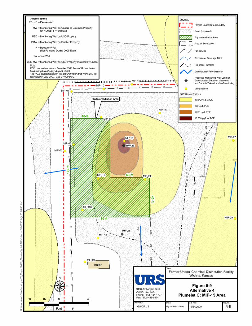
!A
!A
!(
!(
!(
!(
!(
!(
!(
!(
!(
!(
!(
!(
!(
!(
!(
!(
!(
!(
Two 50-ft HRC Barriers,15-30 ft bgs
Phytoremediation Area
40-ft
40-ft
80-ft
40-ft
100-f
t
Trailer
MIP-29
MIP-28
MIP-24
MIP-23
MIP-22
MIP-27
MIP-14
MIP-16
MIP-15
MIP-13
MIP-12
MIP-11
MIP-10
MIP-03a
MIP-04
MIP-03
MIP-02
MIP-01
MW-28
MW-26
Former Unocal Chemical Distribution FacilityWichita, Kansas
9400 Amberglen Blvd.Austin, TX 78729Phone: (512) 454-4797Fax: (512) 419-5474
Client:
Drawn by: Date:GWC/AUS
µ30 0 3015
Feet Fig 5-9 MIP-15.mxd 6/24/2009
LegendFormer Unocal Site Boundary
Road (Unpaved)
Phytoremediation AreaA
A
O
O
E
E Area of Excavation
X Fence Line
Stormwater Drainage Ditch
Historical Plumelet
Groundwater Flow Direction
!AProposed Monitoring Well LocationGroundwater Elevation Measuredand Sample Taken for MNA Monitoring
!( MIP LocationPCE Concentrations
5 µg/L PCE (MCL)
100 µg/L PCE
1,000 µg/L PCE
10,000 µg/L of PCE
Q:\U
noca
l-Wich
ita\D
rawing
s\FS_
Repo
rt\20
09_M
arch\F
ig 5-9
MIP
-15.m
xd 6/
24/20
09 @
10:28
:30 AM
GIS File: Figure:
Figure 5-9Alternative 4
Plumelet C: MIP-15 Area
5-9
= Piezometer= Monitoring Well on Unocal or Coleman Property (D = Deep, S = Shallow)= Monitoring Well on USD Property= Monitoring Well on Pinsker Property= Recovery Well (Not Pumping During 2005 Event)= Test Well= Monitoring Well on USD Property Installed by Unocal
PZ or PMW
USDPMW
R
TWUSD-MW
Abbreviations
Note:PCE concentrations are from the 2008 Annual GroundwaterMonitoring Event (July-August 2008).The PCE concentration in the groundwater grab from MW-15(collected in July 2007) was 27,000 µg/L.
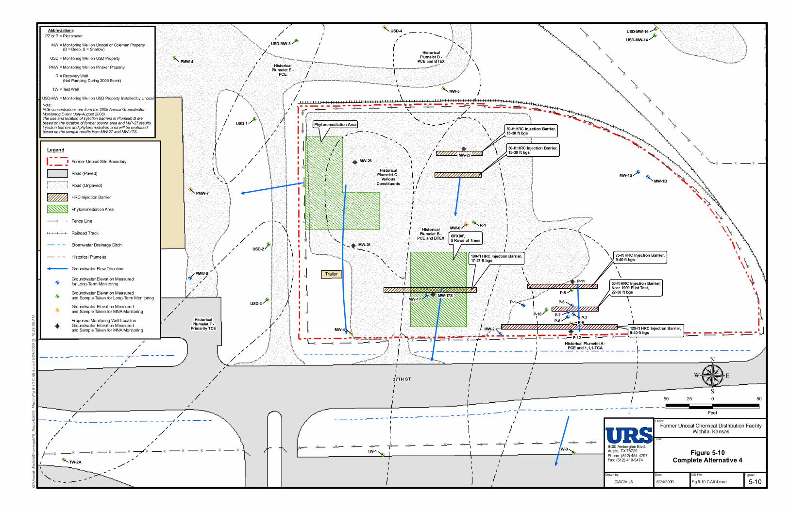
!A
!A
!A
!A
!A
!A
!A
!A
!A
!A
!A
!A
!A
!A
!A
!A
!A
!A
!A
!A!A
!A
!A
!A
!A!A
!A
!A
!A
!A
!A!A
!A
!A
!A
!A
!A
!A
!A
!A
!A
Historical Plumelet A -PCE and 1,1,1-TCA
HistoricalPlumelet B -
PCE and BTEX
HistoricalPlumelet D -
PCE and BTEX
HistoricalPlumelet C -
VariousConstituents
HistoricalPlumelet E -
PCE
HistoricalPlumelet F -
Primarily TCE 125-ft HRC Injection Barrier, 9-40 ft bgs
50-ft HRC Injection Barrier,Near 1999 Pilot Test,22-30 ft bgs
75-ft HRC Injection Barrier,9-40 ft bgs
50-ft HRC Injection Barrier,15-30 ft bgs
60'X80',8 Rows of Trees
100-ft HRC Injection Barrier,17-27 ft bgs
50-ft HRC Injection Barrier,15-30 ft bgs
Phytoremediation Area
Trailer
USD-3
USD-2
USD-1
TW-3
TW-2A
TW-1
R-1
PMW-5
PMW-4
P-9P-8P-7
P-6P-5
P-2P-10
P-1
MW-5
MW-4
USD-MW-3
MW-2
MW-1SMW-1D
MW-17
USD-MW-16USD-MW-14
PMW-8
PMW-7
MW-6
USD-4
37TH ST
MW-28
MW-26MW-27
MW-17S
P-12
P-11
9400 Amberglen Blvd.Austin, TX 78729Phone: (512) 454-4797Fax: (512) 419-5474
Client:
Title:
Drawn by: Date: GIS File: Figure:GWC/AUS
Former Unocal Chemical Distribution FacilityWichita, Kansas
Q:\U
noca
l-Wich
ita\D
rawing
s\FS_
Repo
rt\20
09_M
arch\F
ig 5-1
0 C Al
t 4.m
xd 6/
24/20
09 @
10:28
:50 AM
6/24/2009 Fig 5-10 C Alt 4.mxd
50 0 5025
Feet
µ
LegendFormer Unocal Site Boundary
Road (Paved)
Road (Unpaved)
HRC Injection Barrier
Phytoremediation Area
X Fence Line
Railroad Track
Stormwater Drainage Ditch
Historical Plumelet
Groundwater Flow Direction
!AGroundwater Elevation Measuredfor Long-Term Monitoring
!AGroundwater Elevation Measuredand Sample Taken for Long-Term Monitoring
!AGroundwater Elevation Measuredand Sample Taken for MNA Monitoring
!AProposed Monitoring Well LocationGroundwater Elevation Measuredand Sample Taken for MNA Monitoring
= Piezometer= Monitoring Well on Unocal or Coleman Property (D = Deep, S = Shallow)= Monitoring Well on USD Property= Monitoring Well on Pinsker Property= Recovery Well (Not Pumping During 2005 Event)= Test Well= Monitoring Well on USD Property Installed by Unocal
PZ or PMW
USDPMW
R
TWUSD-MW
Abbreviations
Note:PCE concentrations are from the 2008 Annual GroundwaterMonitoring Event (July-August 2008).The use and location of injection barriers in Plumelet B arebased on the location of former source area and MIP-27 results.Injection barriers and phytoremediation area will be evaluatedbased on the sample results from MW-27 and MW-17S.
Figure 5-10Complete Alternative 4
5-10

Former Unocal - FS Report Page 6-1 Final Revision 1 Wichita, Kansas June 2009
6.0 Evaluation and Comparison of Remedial Action Alternatives
The remedial action alternatives were evaluated based on the criteria provided in Section 5.3.
6.1 Alternative 1: No Action
6.1.1 Overall Protection of Human Health and Environment Alternative 1 would include LTM of the Site and adjacent properties in accordance with the Sampling and Analysis Plan (URS, July 2008), but no additional actions would be taken to protect human health and the environment. While the site is currently unoccupied, fenced, and locked, there would be no institutional or use controls to prevent unauthorized access to site groundwater in the future. Therefore, this alternative would not adequately protect human health and the environment.
6.1.2 Compliance with ARARs The ARARs and To Be Considered guidelines (TBCs) for this alternative are below (see Appendix E for further discussion on the identification process).
Chemical-Specific ARARs
• National Primary Drinking Water Standards (40 CFR Part 141) • Kansas Drinking Water Standards ([Kansas Administrative Regulations (KAR)]
Title 28, Article 15)
Location-Specific ARARs
• None
Action-Specific ARARs
• None
TBCs
• Risk-Based Standards for Kansas RSK Manual – 4th Version
Of particular note are the MCLs (drinking water standards) and KDHE RSK Tier 2 standards for PCE (5 μg/L), TCE (5 μg/L), and vinyl chloride (2 μg/L). These chemical-specific ARARs are currently being exceeded and this alternative takes no action to address this condition. Accordingly, Alternative 1 would not comply with ARARs.

Former Unocal - FS Report Page 6-2 Final Revision 1 Wichita, Kansas June 2009
6.1.3 Long-Term Effectiveness and Permanence Under the “No Action” scenario, there are no institutional controls to prevent near-term future human exposures to contaminated groundwater. EPCs are more than 100 times greater than the RSK Standards, and represent an unacceptable residual risk. Five-year reviews would be required until contaminant concentrations decrease to levels that would allow for unlimited use and unrestricted exposures.
6.1.4 Reduction in Toxicity, Mobility, or Volume through Treatment Alternative 1 does not include a treatment action and, therefore, would not provide any reduction in toxicity, mobility, or volume through treatment. However, natural attenuation processes would continue to lower overall contaminant concentrations in groundwater and limited vadose zone soil potentially contributing to groundwater contamination.
6.1.5 Short-Term Effectiveness Short-term effectiveness during implementation of this alternative (i.e., groundwater monitoring) would not pose a significant risk to workers or the environment. The risk to the community would only be increased if the groundwater were collected and used in a manner that would increase human exposures. However, remedial action objectives would not be achieved.
6.1.6 Implementability Alternative 1 is easily implemented since a well network currently exists at the Site and adjacent properties for LTM, and no other actions would be performed.
6.1.7 Cost Based on the calculations presented in Appendix F, the estimated lifetime cost for Alternative 1 is $1,326,440. This estimate is based on 30 years of groundwater monitoring for this alternative. The estimated cost per year is presented in Table 6-1.
6.2 Alternative 2: Monitored Natural Attenuation and the Environmental Use Control Program
This alternative includes the LTM from Alternative 1 plus MNA and the EUC program.
6.2.1 Overall Protection of Human Health and Environment Under Alternative 2, the EUC program would protect human health associated with the source areas by preventing exposure to existing contamination; however, it would not reliably address potential contaminant migration from the Site. MNA would be used to evaluate the contaminant fate and transport as it relates to potential human exposure, as well as off-site migration.

Former Unocal - FS Report Page 6-3 Final Revision 1 Wichita, Kansas June 2009
The EUC program would reduce the risk of exposure by restricting the future use of the Site to non-residential use and limiting the exposure pathways for groundwater (i.e., exposure to groundwater via ingestion, inhalation, and dermal contact).
MNA would degrade the contaminants in the Plumelet C source area and the residual contamination in Plumelets D, E, and F. The source area for historical Plumelet C has significant concentrations of both petroleum hydrocarbons and chlorinated solvents. Based on the rate of natural degradation seen previously at the Site, the concentrations of both types of contaminants will likely decrease, reducing the risk of exposure and the potential for migration off-site for this plumelet. MNA would also reduce the potential for migration for Plumelets D, E, and F. These plumelets have remained relatively stable in terms of contaminant extent in recent years with concentrations of most chlorinated constituents decreasing.
For Plumelet B, some natural degradation is occurring in areas that contain significant petroleum hydrocarbon concentrations. However, these conditions do not exist over the entire source area. Additionally, petroleum hydrocarbons are generally absent from Plumelet A, minimizing the potential degradation of chlorinated contaminants in that area. Therefore, it is considered unlikely that MNA would adequately prevent the migration of contaminants or reduce the on-site concentrations of COCs to the KDHE RSK Tier 2 standards for Plumelets A and B within a reasonable timeframe.
6.2.2 Compliance with ARARs The ARARs and TBCs for this alternative are below (see Appendix E for further discussion on the identification process).
Chemical-Specific ARARs
• National Primary Drinking Water Standards (40 CFR Part 141) • Kansas Drinking Water Standards (KAR Title 28, Article 15)
Location-Specific ARARs
• None
Action-Specific ARARs
• Occupational Health and Safety Administration (OSHA) (29 CFR Parts 1910 and 1926)
• Kansas Solid Waste Management Regulations (KAR Title 28, Article 29) • Kansas Water Well Construction and Abandonment (KAR Title 28, Article 30) • Kansas EUC Program (KAR Title 28, Article 73)

Former Unocal - FS Report Page 6-4 Final Revision 1 Wichita, Kansas June 2009
TBCs
• Risk-Based Standards for Kansas RSK Manual – 4th Version
Of particular note are the MCLs (drinking water standards) and KDHE RSK Tier 2 standards for PCE (5 μg/L), TCE (5 μg/L), and vinyl chloride (2 μg/L). Natural attenuation processes would eventually comply with chemical-specific ARARs and TBCs at the Site. However, as discussed further in the below criteria, due to minimal natural attenuation observed at Plumelet A and the lack of actions being taken, compliance would not be achieved in a reasonable timeframe, Standard work processes would ensure compliance with the action-specific ARARs. There are no location-specific ARARs for this alternative.
6.2.3 Long-Term Effectiveness and Permanence The EUC Program would provide an adequate and reliable control to prevent human exposure to on-site contaminants exceeding KDHE RSK Tier 2 residential standards and the associated health risks. Although MNA alone would lower contaminant concentrations for Plumelets B and C, the approach is not considered reliable for preventing off-site migration or reducing on-site concentrations to KDHE RSK Tier 2 standards in a reasonable timeframe due to the high concentrations of contaminants in the source areas. However, MNA is considered reliable to prevent the migration and reduce the concentrations of contaminants within Plumelets D, E, and F. These plumelets will be monitored annually for five years. After five years, a review will be performed to evaluate the effectiveness of MNA for those plumelets. If results from the annual events or five year review indicate that the plumelets are expanding, an active remedial measure (i.e. enhanced reductive dechlorination) will be implemented.
6.2.4 Reduction in Toxicity, Mobility, or Volume through Treatment Alternative 2 does not include a treatment action and, therefore, would not provide any reduction in toxicity, mobility, or volume through treatment. However, natural attenuation processes would continue to lower overall contaminant concentrations in groundwater and limited vadose zone soil potentially contributing to groundwater contamination.
6.2.5 Short-Term Effectiveness Implementing institutional controls through the EUC Program would be protective of the community during implementation of remedial actions. Short-term effectiveness during on-site activities (i.e., monitoring) would not pose a significant risk to the community, workers, or the environment. During implementation of the alternative, the short-term risk to the environment (e.g., downgradient migration) would be unaffected by this alternative (as compared to the no-action alternative).
Former Unocal - FS Report Page 6-5 Final Revision 1 Wichita, Kansas June 2009
RAOs relating to protection of human health would be formally achieved within a few months for the Site as part of implementation of institutional controls. However, this alternative is unlikely to achieve RAOs for protection of the environment (i.e., prevent off-site migration, reduce on-site concentrations to KDHE RSK Tier 2 standards) within a reasonable time frame.
6.2.6 Implementability
Alternative 2 is easily implemented since a well network currently exists at the Site and adjacent properties for MNA and LTM. The needed services for monitoring are readily available. The application for EUC program would also be easily completed and submitted for regulatory review. Implementing this alternative also would not hinder the application of additional remedial actions in the future if necessary.
Implementation of Alternative 2 would be subject to the Bureau of Environmental Remediation Policy # BER-RS-042, which requires demonstration of seven “Criteria for Determining when MNA may be Appropriate:”
1) Threat to Human Health 2) Degradation of Ground Water 3) Degradation of Surface Water 4) Threat to Other Potential Receptors 5) Time Frame and Cost 6) Property Control 7) Resource Management
If the selected alternative consists of a natural attenuation component, these criteria will be evaluated and documented during the Proposed Plan/Remedial Design Phases of implementation.
6.2.7 Cost Based on the calculations presented in Appendix F, the estimated lifetime cost for Alternative 2 is $1,733,262. This estimate is based on capital expenses during Year 1 and 30 years of groundwater monitoring for natural attenuation. The estimated cost per year is presented in Table 6-1.
6.3 Alternative 3: Enhanced Reductive Dechlorination This alternative includes the technologies presented in Alternative 2 plus enhanced reductive dechlorination.
Former Unocal - FS Report Page 6-6 Final Revision 1 Wichita, Kansas June 2009
6.3.1 Overall Protection of Human Health and Environment In addition to the protection provided by the EUC program and MNA, Alternative 3 further protects human health and the environment by enhancing the natural degradation processes in the source areas of Plumelets A and B at the Site. For historical Plumelets A and B, enhanced reductive dechlorination would provide electron donor material (HRC®) that would enhance contaminant degradation. Additionally, biobarriers comprised of HRC® would be implemented downgradient of the source areas to reduce the potential for off-site migration.
MNA would still be the primary technology for the source area for historical Plumelet C; however, biobarriers would be implemented on the western and southern sides of the plumelet to more reliably address potential migration of the contaminants off-site. MNA would also remain the primary technology for Plumelets D, E, and F. These plumelets have remained relatively stable in terms of contaminant extent in recent years with concentrations of most chlorinated constituents decreasing. Therefore, MNA alone would protect human health and the environment for these plumelets. These plumelets will be monitored annually for five years. After five years, a review will be performed to evaluate the effectiveness of MNA for those plumelets.
Therefore, due to the reduced contaminated mass and low potential risk for off-site migration, Alternative 3 would significantly protect human health and the environment at the Site, and the RAOs would be achieved.
6.3.2 Compliance with ARARs The ARARs and TBCs for this alternative are below (see Appendix E for further discussion on the identification process).
Chemical-Specific ARARs
• National Primary Drinking Water Standards (40 CFR Part 141); • Kansas Drinking Water Standards (KAR Title 28, Article 15);
Location-Specific ARARs
• None
Action-Specific ARARs
• Federal Underground Injection Program (UIC) Standards (40 CFR Parts 144-147) • Federal Department of Transportation Regulations (49 CFR Parts 171-173) • OSHA (29 CFR Parts 1910 and 1926) • Kansas Solid Waste Management Regulations (KAR Title 28, Article 29) • Kansas Water Well Construction and Abandonment (KAR Title 28, Article 30) • Kansas UIC Program (KAR Title 28, Article 46)
Former Unocal - FS Report Page 6-7 Final Revision 1 Wichita, Kansas June 2009
• Kansas EUC Program (KAR Title 28, Article 73)
TBCs
• Risk-Based Standards for Kansas RSK Manual – 4th Version
Of particular note are the MCLs (drinking water standards) and KDHE RSK Tier 2 standards for PCE (5 μg/L), TCE (5 μg/L), and vinyl chloride (2 μg/L). Enhanced reductive dechlorination in combination with natural attenuation processes would comply with chemical-specific ARARs and TBCs for Plumelets A, B, and C in a reasonable timeframe. Additionally, natural attenuation processes would comply with chemical-specific ARARs and TBCs for off-site Plumelets D, E, and F in a reasonable timeframe. Standard work processes would ensure compliance with the action-specific ARARs. There are no location-specific ARARs for this alternative.
6.3.3 Long-Term Effectiveness and Permanence The EUC Program would provide an adequate and reliable control to prevent human exposure to contaminants exceeding KDHE RSK Tier 2 residential standards and the associated health risks. Based on the 1999 and 2006 pilot test results, barriers comprised of HRC® can last up to five years without contaminant breakthrough. Through groundwater monitoring and periodic reinjections (moderate O&M requirements), enhanced reductive dechlorination would be an adequate and reliable approach to preventing off-site migration and the associated protection of the environment, particularly for chlorinated hydrocarbons which are the primary COCs. This approach is marginally reliable for fuel-related compounds like naphthalene and benzene. Overall, this remedial approach is among the more reliable approaches for reducing on-site concentrations to KDHE RSK Tier 2 standards in a reasonable time frame.
6.3.4 Reduction in Toxicity, Mobility or Volume through Treatment Enhanced reductive dechlorination would provide active treatment of the groundwater to accelerate natural degradation processes that irreversibly degrades contaminants. The fundamental degradation pathway is:
PCE → TCE → cis- or trans-1,2-DCE → vinyl chloride → ethene → CO2 and H2O
These chemicals have varying levels of toxicity, with vinyl chloride being the most toxic. Ultimately, the contaminants would be degraded to ethenes, CO2, and H2O, which are non-toxic. Accordingly, degradation reduces the toxicity and volume of the contaminants. The mobility of these chemicals are not appreciably different, but lower concentrations cannot travel as far before attenuating to levels below the KDHE RSK Tier 2 standards. Accordingly, this treatment also reduces contaminant mobility.

Former Unocal - FS Report Page 6-8 Final Revision 1 Wichita, Kansas June 2009
Natural degradation processes would continue to reduce contaminant toxicity, mobility, and volume in limited vadose zone soil potentially contributing to groundwater contamination; but this reduction would not be achieved through treatment.
6.3.5 Short-Term Effectiveness Implementing institutional controls through the EUC Program would be protective of the community during remedial actions. Short-term effectiveness during on-site activities (i.e., monitoring and injections) would not pose a significant risk to the community, workers, or the environment. Implementation of the alternative would have a beneficial impact on the environment by reducing the toxicity, mobility, and volume of contaminants.
RAOs relating to protection of human health would be formally achieved within a few months on the Site as part of implementation of institutional controls (i.e., the EUC Program). Similarly, within a few months of the HRC® injections, RAOs relating to preventing contaminant migration would be achieved, based on the results of the 1999 pilot test. The timeframe required to achieve the RAO of reducing on-site concentrations to KDHE RSK Tier 2 standards may not be reliably predicted due to the heterogenity and complexity of the site. But, approximately 2 or 3 HRC® injection events on a 5-year schedule may be needed (Appendix D).
6.3.6 Implementability Enhanced reductive dechlorination has been implemented in two prior pilot tests at or near the site. Therefore, based on the successful implementation of the previous pilot tests (1999 and 2006), this technology should be implementable in the desired locations and at the desired depths. The needed services and equipment are readily available.
6.3.7 Cost Based on the calculations presented in Appendix F, the estimated lifetime cost for Alternative 3 is $1,409,848. This estimate is based on capital expenses during Years 1, 5 and 10 (assuming they are needed), plus 15 years of groundwater monitoring costs. The estimated cost per year is presented in Table 6-1.
6.4 Alternative 4: Enhanced Reductive Dechlorination and Phytoremediation
This alternative includes the technologies presented in Alternative 3 plus phytoremediation.
6.4.1 Overall Protection of Human Health and Environment In addition to the protection provided by enhanced reductive dechlorination, the EUC program, and MNA, Alternative 4 further increases the protection to human health and the environment by creating hydraulic barriers and providing contaminant destruction using phytoremediation. For
Former Unocal - FS Report Page 6-9 Final Revision 1 Wichita, Kansas June 2009
historical Plumelet A, phytoremediation would not be used due to the thickness of the saturated zone (from 9 to 40 ft bgs). However, at Plumelets B and C, phytoremediation would be used as long-term hydraulic barriers to prevent contaminants from migrating off-site.
Alternative 4 would reduce the contaminant concentrations in all Plumelets A, B, and C. Additionally, this alternative would reduce the risk of contaminant migration off-site in both the short- and long- terms associated with these plumelets. MNA would also remain the primary technology for Plumelets D, E, and F. These plumelets have remained relatively stable in terms of contaminant extent in recent years with concentrations of most chlorinated constituents decreasing. Therefore, MNA alone would protect human health and the environment for these plumelets. These plumelets will be monitored annually for five years. After five years, a review will be performed to evaluate the effectiveness of MNA for those plumelets. Therefore, the RAOs would be achieved under this alternative within a reasonable time frame.
6.4.2 Compliance with ARARs The ARARs and TBCs for this alternative are below (see Appendix C for further discussion on the identification process).
Chemical-Specific ARARs
• National Primary Drinking Water Standards (40 CFR Part 141); • Kansas Drinking Water Standards (KAR Title 28, Article 15);
Location-Specific ARARs
• None
Action-Specific ARARs
• Federal UIC Standards (40 CFR Parts 144-147) • Federal Department of Transportation Regulations (49 CFR Parts 171-173) • OSHA (29 CFR Parts 1910 and 1926) • Kansas Solid Waste Management Regulations (KAR Title 28, Article 29) • Kansas Water Well Construction and Abandonment (KAR Title 28, Article 30) • Kansas UIC Program (KAR Title 28, Article 46) • Kansas EUC Program (KAR Title 28, Article 73)
TBCs
• Risk-Based Standards for Kansas RSK Manual – 4th Version
Of particular note are the MCLs (drinking water standards) and KDHE RSK Tier 2 standards for PCE (5 μg/L), TCE (5 μg/L), and vinyl chloride (2 μg/L). Enhanced reductive dechlorination in combination with phytoremediation and natural attenuation processes for Plumelets B and C

Former Unocal - FS Report Page 6-10 Final Revision 1 Wichita, Kansas June 2009
would comply with chemical-specific ARARs and TBCs in a reasonable time frame. Additionally, enhanced reductive dechlorination in combination with natural attenuation processes would comply with chemical-specific ARARs and TBCs for Plumelet A in a reasonable timeframe, while natural attenuation processes would comply with chemical-specific ARARs and TBCs for off-site Plumelets D, E, and F in a reasonable timeframe. Standard work processes would ensure compliance with the action-specific ARARs. There are no location-specific ARARs for this alternative.
6.4.3 Long-Term Effectiveness and Permanence The EUC Program would provide an adequate and reliable control to prevent human exposure to contaminants exceeding KDHE RSK Tier 2 residential standards and the associated health risks.
Based on the 1999 pilot test results, barriers comprised of HRC® can last at least five years without contaminant breakthrough. In combination with groundwater monitoring and periodic reinjections, enhanced reductive dechlorination would be an adequate and reliable approach to preventing off-site migration and the associated protection of the environment from Plumelet A. Overall, this remedial approach is among the more reliable approaches for reducing on-site concentrations to KDHE RSK Tier 2 standards in a reasonable time frame.
Plumelets B and C also include a phytoremediation component that would provide an adequate and reliable control to contaminant migration, and increased potential for reducing contaminant concentrations to KDHE RSK Tier 2 standards. In addition to in situ degradation, phytoremediation also provides contaminant uptake and hydraulic control to lower concentrations and prevent contaminant migration. Finally, phytoremediation would continue to be effective indefinitely with low O&M requirements.
6.4.4 Reduction in Toxicity, Mobility, or Volume through Treatment Enhanced reductive dechlorination would provide active treatment of the groundwater that accelerates natural degradation processes that irreversibly degrades contaminants. Ultimately, degradation results in ethenes, CO2, and H2O which are non-toxic.
Similarly, phytoremediation enhances degradation of chlorinated solvents in the root zone, but also uptakes and phytovolatilizes the contaminants to the atmosphere. These processes irreversibly destroy the contaminants and lower their toxicity and volume through treatment. Also, phytoremediation uptakes groundwater and depresses the water table. This provides hydraulic control that influences groundwater flow patterns and reduces contaminant mobility from the site.
Former Unocal - FS Report Page 6-11 Final Revision 1 Wichita, Kansas June 2009
With regard to the limited vadose zone soil potentially contributing to groundwater contamination, phytoremediation would provide treatment that would reduce toxicity, mobility, and volume of contaminants. However, the preliminary design does not place the phytoremediation component in the source areas where there are elevated concentrations in vadose zone soil. Nonetheless, natural degradation processes would continue to reduce contaminant toxicity, mobility, and volume in limited vadose zone soil potentially contributing to groundwater contamination; but this reduction would not be achieved through treatment.
6.4.5 Short-Term Effectiveness Implementing institutional controls through the EUC Program would be protective of the community during remedial actions. Short-term effectiveness during on-site activities (i.e., monitoring, injections, and tree planting) would not pose a significant risk to the community, workers, or the environment. After construction, the alternative would have a beneficial impact on the environment by reducing the toxicity, mobility, and volume of contaminants.
RAOs relating to protection of human health would be formally achieved on the Site within a few months as part of implementation of institutional controls. Similarly, within a few months of the HRC® injections, RAOs relating to preventing contaminant migration would be achieved, based on the results of the 1999 pilot test. Phytoremediation components, and their associated benefits of contaminant treatment and hydraulic control, require approximately 5 years to become established; however, MNA processes also would serve to address contaminant migration during phytoremediation establishment time.
The timeframe required to achieve the RAO of reducing on-site concentrations to KDHE RSK Tier 2 standards may not be reliably predicted due to the heterogeneity and complexity of the site. At least 2 or 3 HRC® injections on a 5-year schedule could be anticipated in Plumelet A (Appendix C). For Plumelets B and C, the phytoremediation system should eventually achieve this RAO in a timeframe less than that of the single injection of HRC® alone.
6.4.6 Implementability Enhanced reductive dechlorination has been implemented in two prior pilot tests at or near the site. Therefore, based on the successful implementation of the previous pilot tests (1999 and 2006), this technology should be implementable in the desired locations and at the desired depths. The needed services and equipment are readily available. Similarly, phytoremediation has been readily implemented at similar sites. The needed services and equipment are readily available.
Former Unocal - FS Report Page 6-12 Final Revision 1 Wichita, Kansas June 2009
6.4.7 Cost Based on the calculations presented in Appendix F, the estimated lifetime cost for Alternative 4 is $1,440,296. This estimate is based on capital expenses during Years 1, 5 and 10 (assuming they are needed), plus 15 years of O&M and groundwater monitoring for this alternative. The estimated cost per year is presented in Table 6-1.
6.5 Comparative Analysis Table 6-2 provides a summary of the comparative analysis. The primary rationale for the
different ratings among the three active alternatives (Alternatives 2, 3, and 4) are summarized
below.
• Overall Protection of Human Health and the Environment. Alternatives 2, 3, and 4 would all adequately protect on-site human health through institutional controls. However, because Alternative 2 would not mitigate off-site migration of contaminants, it would not be sufficiently protective of the environment. Alternatives 3 and 4 would be sufficiently protective of the environment.
• Compliance with ARARs. All three active alternatives would eventually comply with ARARs, although Alternative 2, which does not employ any active remediation, may not comply with chemical-specific ARARs within a reasonable time frame.
• Long-Term Effectiveness and Permanence. The primary differences in the alternatives relating to this criterion are the reliability of the controls to achieve the RAOs (adequacy and reliability of controls). Through the use of institutional controls, Alternatives 2, 3, and 4 all provide reliable and adequate controls for on-site protection of human health. Alternative 2, however, would not be reliable in preventing off-site migration. Alternative 3 (enhanced reductive dechlorination) performs better with regard to this criterion. However, with the addition of phytoremediation, Alternative 4 has the highest rating.
• Reduction of Toxicity, Mobility, or Volume through Treatment. Alternative 2 does not provide treatment and therefore received a poor rating. Alternatives 3 and 4 would both provide adequate reduction of toxicity, mobility, or volume through treatment, but Alternative 4 with phytoremediation provides additional reduction beyond enhanced reductive dechlorination alone.
• Short-Term Effectiveness. All three active alternatives provide good short-term effectiveness because they adequately protect the community and workers during implementation of the alternatives. None of the alternatives is given an excellent
Former Unocal - FS Report Page 6-13 Final Revision 1 Wichita, Kansas June 2009
rating because of the uncertainty and relatively long timeframes (i.e., potentially greater than 10 years) needed to meet the RAO of reducing on-site contaminant concentrations to KDHE RSK Tier 2 standards.
• Implementability. Alternative 2, by virtue of only using institutional controls and groundwater monitoring, received an excellent rating. Alternatives 3 and 4 have physical components to implement, such as HRC® injections and establishing trees as part of phytoremediation. These activities are routinely performed and HRC® pilot tests have demonstrated implementability. But, potential problems could occur including inadequate delivery (e.g., even distribution) of HRC® material or extreme weather conditions that slow the establishment of trees. Accordingly, these alternatives receive a “Good” rating instead of “Excellent.”
• Cost. Alternative 2 has the highest estimated cost due to the 30 year timeframe and the additional monitoring needed for natural attenuation. Alternatives 3 and 4 have comparable estimated costs with Alternative 3 being slightly lower. Both Alternative 3 and 4 are associated with a 15 year timeframe. Alternative 4 has a higher initial cost than Alternative 3, but lower costs during years 5 and 10.

Former Unocal - FS Report Page 6-14 Final Revision 1 Wichita, Kansas June 2009
Table 6-1. Estimated Costs of Remedial Alternatives
Alternative 1 Alternative 2 Alternative 3 Alternative 4
Year Capital O&M Annual Total Capital O&M
Annual Total Capital O&M
Annual Total Capital O&M
Annual Total
1 $-- $44,215 $44,215 $63,749 $55,650 $119,400 $253,838 $57,388 $311,227 $350,318 $62,988 $413,306 2 $-- $44,215 $44,215 $-- $55,650 $55,650 $-- $57,388 $57,388 $-- $62,988 $62,988 3 $-- $44,215 $44,215 $-- $55,650 $55,650 $-- $57,388 $57,388 $-- $62,988 $62,988 4 $-- $44,215 $44,215 $-- $55,650 $55,650 $-- $57,388 $57,388 $-- $62,988 $62,988 5 $-- $44,215 $44,215 $-- $55,650 $55,650 $170,768 $57,388 $228,156 $97,576 $62,988 $160,564 6 $-- $44,215 $44,215 $-- $55,650 $55,650 $-- $57,388 $57,388 $-- $57,988 $57,988 7 $-- $44,215 $44,215 $-- $55,650 $55,650 $-- $57,388 $57,388 $-- $57,988 $57,988 8 $-- $44,215 $44,215 $-- $55,650 $55,650 $-- $57,388 $57,388 $-- $57,988 $57,988 9 $-- $44,215 $44,215 $-- $55,650 $55,650 $-- $57,388 $57,388 $-- $57,988 $57,988
10 $-- $44,215 $44,215 $-- $55,650 $55,650 $124,415 $57,388 $181,804 $97,576 $57,988 $155,564 11 $-- $44,215 $44,215 $-- $55,650 $55,650 $-- $57,388 $57,388 $-- $57,988 $57,988 12 $-- $44,215 $44,215 $-- $55,650 $55,650 $-- $57,388 $57,388 $-- $57,988 $57,988 13 $-- $44,215 $44,215 $-- $55,650 $55,650 $-- $57,388 $57,388 $-- $57,988 $57,988 14 $-- $44,215 $44,215 $-- $55,650 $55,650 $-- $57,388 $57,388 $-- $57,988 $57,988 15 $-- $44,215 $44,215 $-- $55,650 $55,650 $-- $57,388 $57,388 $-- $57,988 $57,988 16 $-- $44,215 $44,215 $-- $55,650 $55,650 $-- $-- $-- $-- $-- $-- 17 $-- $44,215 $44,215 $-- $55,650 $55,650 $-- $-- $-- $-- $-- $-- 18 $-- $44,215 $44,215 $-- $55,650 $55,650 $-- $-- $-- $-- $-- $-- 19 $-- $44,215 $44,215 $-- $55,650 $55,650 $-- $-- $-- $-- $-- $-- 20 $-- $44,215 $44,215 $-- $55,650 $55,650 $-- $-- $-- $-- $-- $-- 21 $-- $44,215 $44,215 $-- $55,650 $55,650 $-- $-- $-- $-- $-- $-- 22 $-- $44,215 $44,215 $-- $55,650 $55,650 $-- $-- $-- $-- $-- $-- 23 $-- $44,215 $44,215 $-- $55,650 $55,650 $-- $-- $-- $-- $-- $-- 24 $-- $44,215 $44,215 $-- $55,650 $55,650 $-- $-- $-- $-- $-- $-- 25 $-- $44,215 $44,215 $-- $55,650 $55,650 $-- $-- $-- $-- $-- $-- 26 $-- $44,215 $44,215 $-- $55,650 $55,650 $-- $-- $-- $-- $-- $-- 27 $-- $44,215 $44,215 $-- $55,650 $55,650 $-- $-- $-- $-- $-- $-- 28 $-- $44,215 $44,215 $-- $55,650 $55,650 $-- $-- $-- $-- $-- $-- 29 $-- $44,215 $44,215 $-- $55,650 $55,650 $-- $-- $-- $-- $-- $-- 30 $-- $44,215 $44,215 $-- $55,650 $55,650 $-- $-- $-- $-- $-- $-- Grand Total $1,326,440 $1,733,262 $1,409,848 $ 1,440,296
All costs are presented in present day costs.
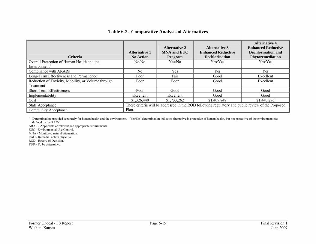
Former Unocal - FS Report Page 6-15 Final Revision 1 Wichita, Kansas June 2009
Table 6-2. Comparative Analysis of Alternatives
Criteria Alternative 1
No Action
Alternative 2 MNA and EUC
Program
Alternative 3 Enhanced Reductive
Dechlorination
Alternative 4 Enhanced Reductive Dechlorination and Phytoremediation
Overall Protection of Human Health and the Environment1
No/No Yes/No Yes/Yes Yes/Yes
Compliance with ARARs No Yes Yes Yes Long-Term Effectiveness and Permanence Poor Fair Good Excellent Reduction of Toxicity, Mobility, or Volume through Treatment
Poor Poor Good Excellent
Short-Term Effectiveness Poor Good Good Good Implementability Excellent Excellent Good Good Cost $1,326,440 $1,733,262 $1,409,848 $1,440,296 State Acceptance Community Acceptance
These criteria will be addressed in the ROD following regulatory and public review of the Proposed Plan.
1 Determination provided separately for human health and the environment. “Yes/No” determination indicates alternative is protective of human health, but not protective of the environment (as defined by the RAOs).
ARAR - Applicable or relevant and appropriate requirements. EUC - Environmental Use Control. MNA - Monitored natural attenuation. RAO - Remedial action objective. ROD - Record of Decision. TBD - To be determined.

Former Unocal - FS Report Page 7-1 Final Revision 1 Wichita, Kansas June 2009
7.0 Recommendation of the Final Remedial Action Alternative
Based on the evaluation and comparison of the remedial action alternatives, Chevron EMC recommends that Alternative 4 (Enhanced Reductive Dechlorination and Phytoremediation) be the proposed remedy.
Former Unocal - FS Report Page 8-1 Final Revision 1 Wichita, Kansas June 2009
8.0 References U.S. Environmental Protection Agency (EPA), 1998. Technical Protocol for Evaluating Natural Attenuation of Chlorinated Solvents in Ground Water. EPA, October 1988. Guidance for Conducting Remedial Investigations and Feasibility Studies Under CERCLA, Interim Final, EPA/540/G-89/004, Office of Solid Waste and Emergency Response (OSWER) Directive 9355.3-01. Federal Remediation Technologies Roundtable (FRTR), October 2008. Technology Screening Matrix and Reference Guide, 4th Edition, http://www.frtr.gov/, accessed October 3, 2008. Ferro, A.M., J. Kennedy, R. Kjelgren, J. Rieder, and S. Perrin. 1999. Toxicity Assessment of Volatile Organic Compounds in Poplar Trees. Internat. J. Phytoremed. 1:9-17. Harding ESE, Inc. (Harding), May 2001. Enhanced Bioremediation Pilot Test Results, Unocal Corporation, Wichita, Kansas. Kansas Department of Health and Environment (KDHE), January, 2008. KDHE Letter regarding Site-Specific Risk Assessment Requirement, Former Unocal Chemical Distribution Facility, Wichita, Kansas. January 17. KDHE, December, 2007. Letter regarding Replacement Pages for the Final Revision 0 Remedial Investigation (RI) Report, Former Unocal Chemical Distribution Facility, Wichita, Kansas. December 19. KDHE, June 2007. Risk-Based Standards for Kansas (RSK) Manual - 4th Version, Kansas Department of Health and Environment, Division of Environment, Bureau of Environmental Remediation. KDHE, April 2006. Environmental Use Controls: Another Tool in the Remediation Tool Box, Kansas Department of Health and Environment, Christine Jump, ASTSWMO IC Roundtable and training, http://epa.gov/superfund/policy/ic/pdfs/jump.pdf. Shapiro and Wilk, May 1992. Supplemental Guidance to Risk Assessment Guidance for Superfund (RAGS): Calculating the Concentration Term, OSWER Directive 9285.7-081. Smith Environmental Technologies Corporation (Smith), 1996. Final Report Phase II RI. Unocal Corporation, Wichita, Kansas. December.

Former Unocal - FS Report Page 8-2 Final Revision 1 Wichita, Kansas June 2009
Terracon, March 2002. Source Area Soil Removal Closure Report, Former Unocal Chemical Distribution Facility, Wichita, Kansas. URS Corporation (URS), December 2008. Enhanced Reductive Dechlorination Pilot Test Results Report, Former Unocal Chemical Distribution Facility, Wichita, Kansas. URS, July 2008. Final Revision 2 Sampling and Analysis Plan, Former Unocal Chemical Distribution Facility, Wichita, Kansas. URS, November 2007. Final Revision 0 Remedial Investigation (RI) Report, Former Unocal Chemical Distribution Facility, Wichita, Kansas. November 21. URS, September 2007. Results of the Membrane Interface Probe (MIP) Investigation, Former Unocal Chemical Distribution Facility, Wichita, Kansas. September 28. URS, October 2006. Enhanced Reductive Dechlorination Pilot Test Implementation Workplan. Former Unocal Chemical Distribution Facility, Wichita, Kansas.

Appendix A
Consent Order
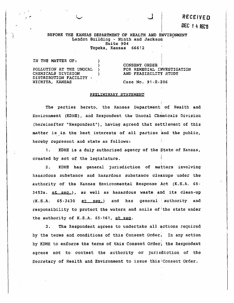
,, ,.. 1._, -.J. I RECEIVE 0 i i DEC 1 4 REC'O I
BEFORE THE KANSAS DEPARTMENT OF HEALTH AND ENVIRONMENT Landon Building - Ninth and Jackson -
Suite 904 Topeka, Kansas 66612
IN THE MATTER OF:
POLLUTION AT THE UNOCAL CHEMICALS DIVISION DISTRIBUTION FACILITY -WICHITA, KANSAS
CONSENT ORDER FOR REMEDIAL INVESTIGATION AND FEASIBILITY STUDY
Case No. 91-E-206
PRELIMINARY STATEMENT
The parties hereto, the Kansas Department oe Health and
Environment (KDHE), and Respondent the Unoca1 Chemicals Division
(hereinafter "Respondent"), having agreed that settlement of this
matter is in the best interests of all parties and the public,
hereby represent and state as follows:
1. KDHE is a duly authorized agency of the State of Kansas,
created by act of the legislature.
2. KDHE has general jurisdiction of matters involving
hazardous substance and hazardous substance cleanups under the
authority of the Kansas Environmental Response Act (K.S.A. 65-
3452a .. et se~.), as well as hazardous waste and its clean-up
(K.S.A. 65-3430 et se~.) and has general authority and
responsibility to protect the waters and soils of!the state under
the authority of K.S.A. 65-161, et sea.
3. The Respondent agrees to undertake all actions required
by the terms and conditions of this Consent Order; In any action
by KDHE to enforce the terms of this Consent Order~ the Respondent
agrees not to contest the authority or jurisdiction of the
Secretary of Health and Environment to issue this!consent Order.

..._.
I
I 4. This Consent Order shall apply to and :be binding upon
i KDHE and the Respondent, its agents, successors, and assigns. The
I
signatories to this Consent Order certify that they are authorized
to execute and legally bind the parties they represent to this
Consent Order. No change in the ownership or cor~orate status of
the Respondent shall alter its responsibilities under this Consent
Order.
5. The Respondent shall provide a copy of this Consent Order
to any subsequent owners or successors before ownership rights are
transferred. The Respondent shall provide a copyJof this Consent
Order to all contractors, sub-contractors, laboratories, and
consultants which are retained to conduct any work' performed under ' this Consent Order, within 14 days after the effective date of this
Consent Order or the date of retaining their services.
Notwithstanding the terms of any contract, ~ Respondent is
responsible for compliance with t~is Consent Orderiand for ensuring
that its contractors and agents comply with this Consent Order.
6. The activities conducted under this Consent Order are
subject to approval by KDHE and shall be undertaken in a manner
that is consistent with the National Contingency Plan (NCP), 40 CFR
Part 300.
7. While the Respondent to this Consent Order does not admit
liability for the contamination at the Unocal Chemicals Division
Distribution Facility and the surrounding environme.nt, nevertheless
it agrees to enter into this Consent Order to prepare a Work Plan

v ) }
\
·. i ---
3
as described in paragraph 24 below, to be attached hereto marked
Exhibit 2 and incorporated herein upon approval by KDHE.
FINDINGS QF FACT
8. The Unocal Chemicals Division Distripution Facility
"Unocal" is located at 2100 East 37th Street in Wichita, Kansas.
The site is also described as being in the Southeast quarter of
the Southwest quarter of Section 27, Township 26: South, Range 1
East.
9. Operations at Unocal generally include receiving bulk
shipments of liquid chemicals, storage of liquid chemicals and
distribution of liquid chemicals. The Unocal facility was
originally constructed in 1953. Unocal handles a variety of
chemicals which include, but are not limited to: ·toluene, methyl
ethyl ketone, xylene, trichloroethy1ene and tetra~hloroethylene. '
1 0. On November 3, 19891 an accident~! release of
approximately 150 gallons of tetrachloroethylene 'was reported to
KDHE. Unocal initia1ly contracted 0. H. Materials' to excavate the
contaminated soil. However, it was determined 1that excavation
operations would not completely remediate the area of contaminated
soil.
11. Unocal contracted Woodward Clyde Consultants to install
a vapor extraction system in the contaminated area. The system
was put into operation on November 22, 1989.

4
1 2 • In March of 1990 a preliminary site
.. _) I I j
I I
characterization was
conducted to identify and assess potential environ.mental concerns
at Unocal. The conclusions of this investigatio~ indicated that
volatile organic chemicals "VOCs" are present in groundwater and
soil beneath the site.
13. A second investigation was conducted at the Unocal
facility on July 29 through August 6, 1991 to supplement data
presented in the initial report. The conclusions of this
investigation confirmed that VOCs were present in ;groundwater and
soil beneath the Unocal site. I
14. The contamination of the groundwater be~eath the Unocal
Chemicals Division Distribution Facility and adjacent areas is
causing or threatens to cause pollution of the waters of the State
or is or threatens to become a hazard to persons,; public health,
or safety.
CONCLUSIONS OF LAW
'
15. Respondent is a "person" within the meanipg of K.S.A. 65-
164, et seq., K.S.A. 65-3430, et seq., and K.S.A. 6~-3452a, et seq.
16. The presence of the contaminants identified in the
groundwater underlying the site constitutes "pollution" as defined
by K.S.A. 65-171d.

... · . ·~
}
\
'
·._j
5
! 17. Some of the contaminants identified in'the groundwater
underlying the site, are "hazardous substances" as defined by
K.S.A. 65-3453 and "hazardous wastes" as defined by K.S.A. 65-
3430.
18. The area defined in paragraph 8 and identified as Unocal I
Chemicals Division Distribution Facility const.:i,.tutes a "site"
within the meaning of K.S.A. 65-3453.
19. The facts above constitute:
a} the discharge, abandonment, or disposal of hazardous
substances or hazardous wastes or;
b) the pollution of the land or waters of the state or
the threat of pollution of the land or waters of the state or;
c) a hazard to persons, property or public health or
threatens to become a hazard to persons, property or public health.
20. Under the facts as shown above, the Kans!as Department of ;
Health and Environment has concluded, and th~ Secretary has
confirmed, that there is a need for a response a9tion to prevent I a continuing release or threat or release of haza~dous substances
and remove the pollution or hazard.
21. The clean up of such discharges is necessary to remove
the pollution or hazard and to protect the public health and safety
and the environment, giving rise to the authority of the Kansas
Department of Health and Environment to enter this agreement. A
necessary part of this clean up is an investigation of the nature
and extent of the threat to the public health or welfare or the
6 '
environment caused by the release or threatened release of
hazardous substances, pollutants, or contaminant~ on or from the
site, an evaluation of alternatives for the appropriate extent of
remedial action to prevent or mitigate the migration of the release
or threatened release of hazardous substances,· pollutants, or
contaminants from the site, a selection of a remedial alternative
and implementation of that alternative.
22. The Kansas Department of Health and Environment has
authority to enter the agreement herein, and to make the findings
of fact and conclusions of law herein stated.
23. The Secretary of Health and Environment is authorized by
K.S.A. 65-3453, K.S.A. 65-164, et seq., K.S.A. 65-3430, et seq, and
the regulations issued pursuant thereto to enter an order
confirming the agreement of the parties, and ordering that the
actions and obligations required by the foregoing 'findings of fact
and conclusions of law, the parties hereto agree to the following
activities and the commitments.
ORDER
24. Within 60 days of the effective date of this Consent
Order, Respondent shall submit a draft Work Plan for KDHE approval
which is consistent with the Statement of Work attached hereto,
marked Exhibit 1. KDHE will provide comments o~ the draft Work
Plan. Within 30 days of receipt of KDHE's comments, Respondent
shall submit for final approval a revised Work Plan that addresses
l 7 I
! KDHE's comments. Upon KDHE approval, the Work P.l,an shall become
'
incorporated into this Consent Order and a part thereof as Exhibit
2.
25. Within 30 days from date of KDHE approval of the Work
Plan, Respondent shall commence the schedule of work and thereafter
implement the tasks detailed in the Work Plan. The work shall be
conducted in accordance with the EPA Remedial Investigation and '
Feasibility Study guidance documents including but not limited to
the "Interim Final Guidance for Conducting Remedia~ Investigations
and Feasibility Studies" under CERCLA (OSWER Directive 9355.3·01)
and with the standards and specifications contained in the work
Plan. '
26. Respondent shall provide preliminary a~d final reports
to KDHE according to the Implementation Schedule contained in
Exhibit 2 in a form responsive to KDHE's comments~ :
27. After KDHE reviews the preliminary reports and after KDHE
reviews the final reports, KDHE shall notify Respondent in writing,
of KDHE' s approval or disapproval of these reports or any part ' thereof. KDHE may also notify Respondent in ~ri ting of KDHE
disapproval of Respondent's implementation of the approved Work
Plan.
28. In the event of any KDHE disapproval l of a submitted
report or disapproval of Respondent's implementation of the
approved Work Plan, KDHE shall send Respondent a Notice of
Disapproval delineating the deficiencies, requiring revisions to
the reports or modified work to cure the deficiencies in the work
\,
\
._J
8
and setting a schedule for response by Respondent~ provided however
that any such requirements are consistent with the objectives of
the Work Plan and Consent Order.
29. I
Thereafter, Respondent shall amend and submit to KDHE
revised reports to cure the deficiencies in !the reports in
accordance with KDHE's requirements. ' 30. KDHE may determine that additional tas~s are necessary i
consistent with the approved Work Plan and this Consent Order in
addition to the approved Work Plan tasks including reports, which
have been completed pursuant to this Consent O~der. KDHE may i
request Respondent to implement any such additio~al tasks within
a timeframe ·specified by KDHE. Failure by Respondent to implement
addi tiona! tasks as requested by KDHE, shall l:>e considered a
violation of this Consent Order.
31. All work performed pursuant to this Co~sent Order shall
be under the direction and supervision of a profe~sional engineer
or geologist with
and remediation.
expertise in hazardous waste si~e investigations j
Within 30 days of the effective date of this
Consent Order, Respondent shall notify KDHE in writing of the name,
title, and qualification of the engineer or geologist, and of any
contractors or subcontractors and their personnel to be used in
carrying out the terms of this Consent Order.
32. Any reports, plans, specifications,! schedules and i
attachments required by this Consent Order are, upon approval by
KDHE, incorporated into this Consent Order. Anf non-compliance i
with such approved reports, plans, specific•tions~ schedules, and

\
)
.. J
9
I attachments shall be considered a violation of this Consent Order.
i I
33. No informal advice, guidance, suggesti9ns, or comments I
by KDHE regarding reports, plans, specifications~ and any other
writing subrni tted to Respondent will be construed as relieving i
Respondent of its obligation to obtain written approval, if and
when required by this Consent Order.
QUALITY ASSURANCE
34. All samples analyzed pursuant to this con'sent Order shall ; !
be analyzed by a laboratory which participate~ in a quality
assurance/quality control program equivalent to that specified in \
the document entitled "USEPA Contract Laboratory P;-ogram Statement !
of Work for Organic Analysis" and USEPA Contract La~oratory Program
Statement of Work for Metals Analysis" ( 1988) ("Contract Lab
Statement of Work") and is approved by KDHE.
35. All sample collection and analysis shalllbe performed in
compliance with EPA-approved methods, including tirn'ing of analyses,
documentation of sample collection, handling and analysis, as
described in the following documents:
a. "NEIC Manual for Ground i
Water/Subsurface
Investigations at Hazardous Waste Sites," Document
No. EPA/330/9-81-002; and
b. Contract Lab Statement of Work.
36. Laboratory deliverables as specified in the Contract Lab
Statement of Work shall be submitted to KDHE for all analytical

I \ }
10 I I I
work performed pursuant to this Consent Order. Any~ deviations from
the procedures and methods set forth in these documents must be
approved in writing by KDHE prior to use.
37. Respondent shall use the quality assurance, quality
control, and chain of custody procedures specified in the Quality
Assurance Project Plan~ which is part of the Wor~ Plan, for all
sample collection and analysis performed pursuantito this Consent
Order. I
38. All contracts for field work and laboratory analysis
shall provide that KDHE representatives are allowed access, for
auditing and evaluation purposes, at reasona~le times upon I
reasonable request, to all laboratories and personnel utilized by
Respondent for sample collection and analysis and other field work. i
Upon request by KDHE, the laboratories shall per~orm analysis of l ' a reasonable number of known sa~ples provid~d by KDHE to
demonstrate the quality of the analytical data.
REPORTING
i 39. Respondent shall provide KDHE with written progress
j
reports quarterly, pursuant to the effective date!of this Consent i
Order. At a minimum, these progress reports shall: (1) describe i
the actions, progress, and status of projects which1 have been taken
toward achieving compliance with this Consent Orde~, as well as the I
actions which are scheduled for the next quarter; (2) identify any
requirements under this Consent Order that were not completed as
( ) 11
provided and any problem areas and anticipated P,roblem areas in
complying with this Consent Order; and (3) includ~ all results of
sampling, tests, data, and conclusions drawn from data generated
pursuant to the Work Plan(s).
ACCESS I I I
40. KDHE and any of its agents or contractors is authorized ' i by Respondent to enter and freely move about all jProperty at the I
site for the purposes of, inter alia; interviewin~ site personnel I and contractors; inspecting records, operating log~, and contracts I
related to the activities set out in the Work Plan; reviewing the
progress of Respondent in carrying out the terms !of this Consent
Order; -conducting such sampling and tests as KDHE ~eems necessary;
using a camera, sound recording, or I
other djcumentary type
equipment; and verifying the reports and data subm~tted to KDHE by
Respondent. All such activities of KDHE shall b~ limited to the
work contemplated by the Consent Order. Respond~nt shall permit
such persons to inspect and copy all records, fil~s, photographs, i
documents, and other writings, including all; sampling and I
monitoring data, that pertain to work undertaken pursuant to this
paragraph. During such activities, KDHE to follow
established safety standards.
41. To the extent that work required by thJ Work Plan must ! I
be done on property not owned or controlled !by Respondent, I
Respondent shall use its best efforts to obtain site access
12
agreements from the present owner(s) of such proper~y within thirty I
(30) days of the effective date of this Conse,t Order. Best
efforts includes, but is not limited to, reasonjble payment of
monies to the property owner. Any such access agleement shall be
incorporated by reference into this Consent Orde~. In the event j
that agreements for site access are not obtained wifhin thirty {30) I
days of the effective date of this Consent Order, 'espondent shall
notify KDHE regarding both the lack of and its f~ilure to obtain
such agreements within seven (7) days thereafterf In the event
that KDHE obtains access for Respondent, all r~asonable costs
incurred by KDHE shall be reimbursed by Responder.t. Upon KDHE's
obtaining access for Respondent, Respondent 'hall undertake
approved work on such property. KDHE shall not belresponsible for I
any injury or damage to persons or property caused py the negligent
or willful acts or omissions of Respondent, I its. officers,
employees, agents, successors, assigns, contractols, or any other
person acting on Respondent's behalf in carrying ou any activities
pursuant to the terms of this Consent Order.
DISPUTE RESOLUTION
42. If Respondent disagrees, in whole or in part, with any
approval or other decision by KDHE made pursuant to this Agreement,
Respondent shall notify KDHE within fourteen (14) Talendar days of
receipt of the disapproval. Respondent and KDHE jshall then have
an additional thirty (30) working days to attemp~ to resolve the
13
dispute. If agreement is reached, the resolution rhall be reduced
to writing, signed by each party and incorporate~ thereupon into
this Agreement. If agreement is not reached, the fDHE shall issue
its final decision on the dispute, in writing,! to inform the
Respondent of the decision of KDHE. ! 43. Respondent reserves their right to app~al any decision
of the KDHE, which is not consistent with law or wh~ch is arbitrary I or capricious concerning a dispute under this A~reement, to an
administrative body with applicable jurisdiction a~d thereafter in j
compliance with the Kansas Administrative Procedures Act. The
final decision or resolution of such auth~ity shall be
incorporated as a part of this Agreement. For ~urposes of this
Agreement, final order or decision shall mean an okder or decision
from which no appeal may be taken. The partie~ agree to only
utilize the dispute resolution process in good fatth and not as a
delay tactic, and agree to resolve the dispute ani to expedite to
the extent possible the dispute resolution proces whenever it is
used.
SAMPLING AND PATA/DQCUMENT AYAILABILfTY
I 44. Respondent shall make available to KDH~ all results of
sampling, tests, or other data generated by or on its behalf with
respect to the implementation of this Consent Or,er. Respondent
shall submit these results in the progress reports ~ascribed in the
•• Reporting" Section of this Consent Order. KDHE wi~l make sampling
i
J
14
results and other data available to Respondent.
45. Respondent shall notify RDHE at least seven (7) days
before conductin9 any well drillin9, installation rf equipment, or
sampling. At the request of KDHE, Respondent sp.all provide or I
allow KDHE or its authorized representatives to tafe split samples i
of all samples collected by Respondent pursuant Ito this Consent I
Order. Similarly, at the request o£ Respondent ~DHE shall allow
Respondent or its authorized representatives td take split or I I
duplicate samples of all samples collected by fDHE under this
Consent Order. KDHE sh~11 notify Respondent at ~east seven (7)
days before conducting any samplinq tinder this Consent Order,
provided, however, that if 7 days notice of sa,tnple collection
activity is not possible, KDHE and Respondent j ~hall give such
advance notice to enable each party to have J l
representative
present during said sample collection activity.
RECORD PRESERVATION
I 46. Respondent agrees that it shall presefve, during the
pendency of this Consent Order and for a minimum ~f six (6) years
after its termination, all records and documents! which have not
previously been provided to KDHE in its posseslsion or in the
possession of divisions, employees, agents or consultants or
contractors which relate in any way to this Consent Order or to I
hazardous substance and waste management and dispo~al at the site.
At the concl~sion of six (6) years, Respondent sha1!1 then make such

15
records available to KDHE upon written request f r inspection or
KDHE 1 S retention or shall provide copies of any such records to
KDHE.
STIPULATED PENALTIES
47. For each period of time that Responden~ fail to submit
reports or deliverables at the times set out in Exlibit 2 which is
part of this Consent Order, KDHE may require thaj Respondent pay
as stipulated penalties the following: $2,000 foL the first week
of delay or part thereof; $ 4,000 per day for each ~ay of delay for I
the 8th through 14th day and $ 5,000 per day of d~lay thereafter.
48.
one (21)
shall be
Any stipulated penalties shall be payablj within twenty
days after Respondent Is receipt of demrnd by KDHE and
paid by certified check to:
Secretary of Health and Environmen~ Landon Building - Ninth and Jackso~ Suite 904 I Topeka, Kansas 66612
I A copy of the check and a transmittal letter shalt be sent to the
KDHE contact specified herein. Respondent shall r~mit a check for
the full amount of penalty stated in the demand. i
49. Should Respondent fail to comply with a time requirement
of any tasks required by this consent Order, I the period of I I
noncompliance shall terminate upon Respondent 1 s pe,1formance of said
requirement.
I I I
I
J
16
OTHER CLAIMS AND PARTIES
50. Nothing in this Consent Order shall clnstitute or be
construed as a release for any claim, cause of act~on or demand in
law or equity against any person, firm, partnershi~, or corporation
not a signatory to this Consent Order for any liab~lity it may have
arising out of or relating in any way to the genefation, .storage,
treatment, handling, transportation, release, or,disposal of any
hazardous constituents, hazardous substances, h,zardous wastes,
pollutants, or contaminants found at, taken to, Of taken from the
facility.
OTHER APPLICABLE LAWS
51. All actions required to be taken pursuan~ to this Consent
Order shall be undertaken in accordance with lthe substantive
requirements of all applicable local, state; and federal laws and
regulations.
PROJECT COORDINATORS
52. On or before the effective date of thi~ Consent Order,
KDHE and Respondent shall each designate a Proj~ct Coordinator. I
Each Project Coordinator shall be responsible fo+ overseeing the

' i ' ., \
17
implementation of this Consent Order. The KDHE Project Coordinator I will be KDHE's designated representative. To thf maximum extent I possible, all communications between Respondent 4nd KDHE and all
documents, reports, approvals, and other correspondence concerning I
I the activities performed pursuant to the terms a~d conditions of
this Consent Order, shall be directed throu~h the Project I
Coordinator. The parties agree to provide at lea~t seven (7) days i
written notice prior to changing Project Coordinat?rs. The absence I
of the KDHE Project Coordinator from the Site shfll not be cause
for the stoppage of work.
NOTIFICATION
53. Unless otherwise specified, reports, lotice or other i
submissions required under this Consent Order sha· 1 be in writing
and shall be sent to:
a.
b.
For KDHE Rick Bean, Environmental Geologist Kansas Department of Health and Environment Forbes Field, Bldg. 740 I Topeka, Kansas 66620 j
I For Respondent: Daryl w. Dierwechter Manager of Environmental Unocal Corporation
Affairs j
Unocal Chemicals and Mineral 1700 East Golf Road Shamburg, Illinois 60173
i
Division
\
)
\ j
·...._,
18
REIMBURSEMENT OF COSTS
I
54. I I
a. Six months after the effective date :of this Consent ;
Order and semiannually thereafter, KDHE shall subm1t to Respondent i
an accounting of all oversight costs incurred by KPHE with respect j
to this Consent Order during the previous fiscal year. I
b. KDHE shall submit to Respondent a* accounting for
the cost of performing the Baseline Risk Assessme#t. Upon receipt
of such accounting, Respondent agrees to reirnbur,e KDHE for such
reasonable amounts. KDHE agrees to use a qualifi~d contractor to
perform such Baseline Risk Assessment.
c. KDHE shall submit to Respondent a~ accounting for
the reasonable cost of development of a PlaJ for Community
Relations, and implementation of such Plan. Uponlreceipt of such I
accounting, Respondent agrees to reimburse KDHE for such amount. I KDHE agrees to perform such work itself or ~se a qualified
contractor to develop and implement such Plan. I d. KDHE shall submit to
I I
Respondent the cost of
preparing and maintaining the Administrative Recor~, including but I not limited to photocopying, assembling, mailing, updating, storage I
and other maintenance services. Upon receipt of juch accounting,
Respondent agrees to reimburse KDHE for such reas~nable amounts.
55. Respondent shall, within thirty (30) calendar days from
receipt of said accounting, remit a check for theiamount of those
I I

' J
19 I
costs made payable to the Secretary of Health and Environment.
Checks should specifically reference the identity ~f this site, and
should be addressed to:
Secretary of Health and Environment Landon Building · Ninth and Jackson Suite 904 Topeka, Kansas 6661 2
I A copy of the check and transmittal letter shall! be sent to the
KDHE contact specified herein. Respondent shall r~mit a chedk for
the full amount of those costs.
I i
EFFECTIVE DATE AND SUBSEQUENT MODIFICAtiON
i 56. This Consent Order shall become effective when signed by
i the Secretary of the Department of Health and Envtronment.
57. This Consent Order may be amended by mut~al agreement of
KDHE and Respondent. Such amendments shall be iJ writing, shall !
have as their effective date the date, on which th~y are signed by I
both parties, and shall be incorporated into thiJ Consent Order.
Nothing herein shall limit KDHE's ability to reJuire additional
tasks as set forth in Paragraph 32 herein. I
TERMINATION
58. The provisions of this Consent Order shal~ terminate upon
Respondent's receipt of written notice from KDHE lthat Respondent
has demonstrated that the terms of this Consent Order, including
! \ . I
\ f
~·
20
any additional tasks which KDHE has determined to be necessary have
been satisfactorily completed.
I IN WITNESS WHEREOF, the parties have affixed their signatures
below:
RESPONDENT:
j
Date :_--'3~/t.....,.;.'f....;...l f ...... J-__ _ Manager
STATE OF KANSAS: I I I
~J ;/);,/== AObeit Eye, Q'eneral Counsel
Date: 7/ u~q~ ;
Kansas Depar of Health & Environme
I
Date:-.....:;;.,~~~~~~~?_ I !
CERTIFICATE OF HAILING
I hereby certify that on this £/'/lit day ofi ·-r?Ja«r,A, _, 199~, I deposited a true and correct copy of the above and foregoing Consent Order For Remedial Investigation· and Feasibility Strudy in the United States Mail, postage prepaid, and addressed to: ·
Daryl w. Dierwechter Manager, Environmental Affairs Unocal Chemicals & Minerals Division Unocal Corporation 1700 East Golf Road Schaumburg, Illinois 60173-5862
)
l
GENERAL:
. ......,.,
SCOPE OF WORK FOR A
REMEDIAL INVESTIGATION(RI)/FEASIBILITY STUqY (FS) (Attachment I) :
All work conducted under this Consent Order shall b~ in accordance with the Comprehensive Environmental Response, Co1ttpensation and Liability Act (1980), the Superfund Amendments and ~eauthorization Act (1986), the National Contingency Plan, and; EPA guidance documents. The general activities for an RI/FS that Respondent(s) are required to perform are identified in this Scope of Work. All work performed under this Consent Order shall be in ~ccordance with the Implementation Schedule herein, as defined in the approved Work Plan (Attachment II) , and in full accordance with ithe standards, specifications, and other requirements of the work plans, as approved or modified by KDHE.
SCOPING:
The Respondent will conduct several meetings witp. KOHE to: 1) identify the objectives of the RI/FS process, 2) identify the types of actions that may be required to address site/ contamination problems, 3) identify the need for interim actions to mitigate potential threats, prevent further environmental degradation, or rapidly reduce risks significantly; 4) identify available data sources, and 5) identify the optimal sequence of s~te actions and investigative activities. Information gathered: during these meetings will assist in the development of an RI/FS Work Plan.
OBJECTIVES:
The primary objectives of the Remedial Investigation {RI) are described as follows: I
1)
2)
3)
All significant source areas must pe adequately characterized in order to determine adequ~te remediation and clean-up goals (i.e. type and nature qf source(s) of contaminants, cause of release, estimated quantity of release (s) , and if the release (s) is/Ire active or inactive).
The extent (vertical and horizontal) of, contamination from the site must be characterized (including the migration mechanisms) for the purpose Qf and to the extent necessary for developing and evalu~ting effective remedial alternatives. '
I
To adequately characterize the chemical! and physical properties of the contaminants, their· mobility and persistence in the environment and their 'important fate and transport mechanisms.
4)
5)
6)
,_..
The identification of any human and envirol)mental targets that may be affected by contamination. ;
A risk assessment of contaminant impacts! on identified I
target areas. l To develop individual source control plans for those areas identified as "hot spots" or areas of highest contamination. I
The primary objectives of the Feasibi.lity Study (FS) are described as follows: 1
1)
2)
3)
4)
5)
I To identify and evaluate all approprXate treatment technologies based on infonnation obtained~ during the RI.
I
To screen and assemble appropriate technologies into remedial action alternatives.
To evaluate and refine alternatives based ~n the criteria as defined by the relevant EPA guidance documents.
I To conduct treatability studies or pilot tests to support the effectiveness of certain alternatives.
I
To recommend the most feasible and effe~ti ve remedial action for the site. '
\ RI/FS WORK PLAN:
Within 90 days of the effective date of this qonsent Order, Respondent (s) shall submit to KDHE a draft RI/FS !Work Plan for approval. KDHE will provide comments on the draft RI/FS Work Plan. Within 30 days of receipt of KDHE's comment~, Respondents shall submit for final approval a revised RifFS work Plan that addresses KDHE 's comments. Upon KDHE approval, the RI/FS Work Plan shall become incorporated into this Order and made a part thereof as Attachment II. A Sampling and Ana1ysis Plan, whfch consists of a Field Sampling Plan (FSP) and a Quality Assurance Project Plan (QAPP), and a Site Health and Safety Plan (SHSP) will be submitted with the Work Plan.
DELIVERABLES: l The general activities and subsequent deliverables that the Respondent(s) are required to complete are specified in the USEPA document titled, "Guidance for conducting Remedial Investigations and Feasibility Studies Under CERCLA," and as defined in the Implementation Schedule (Attachment II). KDHE reserves the right to stop Respondent(s) from proceeding further, either temporarily or permanently, on any task, activity or deliverabl~ at any point during the RI/FS.

) COMMUNITY RELATIONS:
\ i
The Respondent(s) shall prepare a community Relations Plan (CRP), in accordance with EPA guidance and the NCP. KDHE shall review and make changes to CRP prior to final approval. . KDHE and the Respondent(s) shall jointly implement the approved plan. The CRP must be approved by KDHE prior to implementation of on-site field activities.
IMPLEMENTATION:
Within 30 days from the date of KDHE approval of theiFSP, QAPP, and SHSP, Respondents shall commence the schedule· of work and thereafter implement the tasks detailed in the RifFS Work Plan.
ADDITIONAL TASKS: I
KDHE may determine that additional tasks are necessary in addition to the approved RifFS Work Plan tasks including reports, which have been completed pursuant to this Order. KDHE may request Respondents to implement any such additional tasks within a timeframe specified by KDHE. Failure by Respondents to implement additional tasks as requested by I<DHE, shall be considered a violation of this consent order.
REPORTS: i Following completion of all field activitied a Remedial Investigation Report must be prepared, which includes all data collected from the field activities. The RI report :shall describe in detail the work completed on-site to accomplish the objectives as set forth in this SOW. 1
In addition, Respondents shall submit a Feasibility Study Report, which evaluates appropriate remedial alternatives\ as determined from information gathered during the RI. The FS Report shall evaluate appropriate remedial alternatives based upon the criteria defined in EPA guidance documents; a detailed analysis of the selected remedial alternative shall also be provided. The noaction alternative must also be considered in: the initial evaluations.
ADMINISTRATIVE DECISION {AD) l I I
After approval of the final Feasibility Study Repo~t, KDHE shall prepare a draft Administrative Decision (AD) on :the preferred remedial alternative as concluded from the RI/FS study. The draft AD shall support the selection of the prefe~red remedial alternative by documenting the following: 1) how the remedy was selected; 2) how the remedy eliminates, reduces, or controls exposures to human and environmental receptors; 3) how the remedy meets federal, state and local remedial requirements; and 4) discussion of remediation goals.
""""'.
KDHE shall publish a notice of the availability of tpe draft AD and provide a public comment period of 30 calendar days. The notice shall include an agency contact person and address, for the submission of written and oral comments on the dra~t AD.
A final AD shall be prepared by KDHE that ibcludes KDHE's explanation for any significant differences between the draft AD and the final AD as well as a responsiveness summary to the public comments. Notice of the final AD will be published in the Kansas Register.

Appendix B
Identification and Screening of Technologies

Appendix B - Identification and Screening of Technologies
General Response
Action Technology Process Option Description
Applicability to Chevron-Wichita
Site (Y/N) Effectiveness Implementability Cost
Process Option Selected for Alternative
Development?No Action NA NA No remedial action is taken to address RAOs. YES Would not affect concentrations or mobility of contaminated
media, nor potential threat to human health and the environment. Remedial approach is not administratively implementable. However, the NCP requires a no-action alternative be developed as a baseline of comparison for other alternatives.
No Capital,No O&M.
YES
Institutional Controls
Monitoring Monitoring Well Periodic sampling and analysis of groundwater samples to guide need for further actions. YES Effective for providing data by which to make remedial decisions.
Readily implementable. A current monitoring well network is present and an annual monitoring program is in place for the Site and adjacent properties. Additional wells as needed may be readily constructed.
Low Capital,Low O&M.
YES
Institutional Controls
Monitoring Potable Water Wells Monitor potable water wells that are screened within or near the delineated extent of contamination. NO NA NA NA NO
Institutional Controls
Monitoring Seeps and Springs Monitor groundwater seepage along hillsides, or into buildings (e.g., basements). NO NA NA NA NO
Institutional Controls
Administrative Environmental Use Control (EUC) Program
Restrict potential exposures to contaminated groundwater through implementation of an environmental use control per KAR Title 28, Article 73.
YES Effective for providing long term risk reduction at the Site by restricting the future use of the Site to non-residential use and restricting invasive activities (well installation and excavation).
Readily implementable. The Site can become part of the EUC program by submitting the necessary paperwork and following the required guidelines.
Low Capital, Low O&M.
YES
Institutional Controls
Physical Alternate Water Supply Provide alternate water supply to all users of potentially affected groundwater. NO NA NA NA NO
Institutional Controls
Physical Point of Use Controls Provide well head treatment (e.g., carbon canisters) to wells screened in affected groundwater. NO NA NA NA NO
Containment Stabilization Adsorption/Solidification Use of portland cement, clays, fly ash, and/or kiln dust to adsorb contaminants and solidify soils with pozzolanic effect.
NO NA NA NA NO
Containment Stabilization Ion Exchange Use of ion exchange media to bind contaminants. NO NA NA NA NOContainment Stabilization Precipitation Alteration of chemical equilibria to reduce solubility of contaminants. NO NA NA NA NO
Containment Subsurface Horizontal Barrier
Grout Injection/Block Displacement Pressure inject grout or slurry at depth below contaminated zone through closely spaced drilled holes to prevent vertical migration.
NO NA NA NA NO
Containment Surface Controls Capping (General) Application of surface barrier to prevent infiltration of surface water which could potentially leach contaminants to groundwater.
YES Would not appreciably mitigate potential contaminant migration, or mitigate contaminant concentrations in groundwater.
Since the Site was razed in 1994, capping would be easy to implement. High Capital,Low O&M.
NO
Containment Vertical Barrier Hydraulic Barrier via Mechanical Extraction
Use groundwater extraction technology to affect groundwater flow direction. YES Effective and proven at the Site in controlling groundwater flow directions.
Mechanical extraction has high O&M component which makes it more difficult to implement over the long term. Approach also requires discharge of collected groundwater and high consumption of energy resources (i.e., electricity).
Moderate Capital, High O&M.
NO
Containment Vertical Barrier Hydraulic Barrier via Phytoremediation
Use phytoremediation to affect groundwater flow direction and reduce the risk of migration of groundwater off-site.
YES Effective. Groves of trees have been demonstrated at other sites to create potentiometric depressions that influence groundwater flow direction.
Readily implementable, but requires several growing seasons before technology is fully operational. The buildings at the Site were razed in 1994, and the Site is currently unused and covered with grass.
Moderate Capital, Low O&M.
YES
Containment Vertical Barrier Slurry Wall, Grout Curtain, or Sheet Pile Wall
Install bentonite/soil slurry, grout, or sheet pile as a physical barrier to prevent horizontal migration of contaminated groundwater. Barrier may be used to fully contain or redirect flow.
YES Effective when used in combination with extraction technique (mechanical or phytoremediation) to achieve desired effectiveness.
Readily implementable for depths where confining layer is 20 ft or less. Installation of physical vertical barriers becomes less implementable with increasing depth, but is possible to anticipated maximum depth of 45 ft for the Site.
High Capital, Low O&M.
NO
Collection Extraction Directional Wells Drilling techniques are used to position wells horizontally, or at an angle, to reach contaminants not accessible by direct vertical drilling.
NO NA NA NA NO
Collection Extraction Dual Phase Extraction A high vacuum system is applied to simultaneously remove various combinations of contaminated ground water, separate-phase petroleum product, and hydrocarbon vapor from the subsurface.
YES Potentially effective removal of groundwater and VOC vapors. Typically used at LNAPL sites (unlike the Site). Dual phase vacuum extraction is more effective than SVE for heterogeneous clays and fine sands, similar to those found at the Site.
Readily implementable, but requires on-going maintenance and consumption of energy resources (i.e., electricity).
Moderate Capital, Moderate O&M
NO
Collection Extraction Extraction Wells Series of conventional vertical and/or horizontal wells to extract contaminated groundwater. YES Groundwater from the Site and adjacent properties was previously extracted, treated and discharged to the City of Wichita sewer system. This method proved to be effectively working.
Readily implementable, but requires on-going maintenance and consumption of energy resources (i.e., electricity).
Low Capital, Moderate O&M
NO
Collection Subsurface Drains Interceptor Trenches Perforated pipe in trenches backfilled with porous media to collect contaminated water. Water is then removed by conventional pumps.
YES Effective for the geology and contaminants found at the Site. Readily implementable given relatively shallow groundwater, but requires on-going maintenance and consumption of energy resources (i.e., electricity). Application over entire saturated zone is possible, but less implementable with increasing depth of confining layer.
High Capital, Moderate O&M.
NO
Ex Situ Treatment Biological/Aerobic Aerated Lagoon or Stabilization Pond Biodegradation in an open lagoon with or without mechanical aeration. YES Effective as a polishing treatment, but not as a primary treatment for concentrations observed at the Site.
Substantial space limitations on the former Unocal facility in which to implement this approach. Also requires an outlet structure for discharge.
Moderate Capital, Low O&M.
NO
Ex Situ Treatment Biological/Aerobic Bioreactors Contaminants in extracted ground water are put into contact with microorganisms in attached or suspended growth biological reactors. In suspended systems, such as activated sludge, contaminated ground water is circulated in an aeration basin. In attached systems, such as rotating biological contractors and trickling filters, microorganisms are established on an inert support matrix.
YES Potentially effective, although spikes in contaminant concentrations can damage microorganism populations used in treatment.
Readily implementable, but requires on-going maintenance and consumption of energy resources (i.e., electricity). No facilities are currently at the Site (i.e., no concrete foundations or buildings).
Moderate Capital, Moderate O&M
NO
Ex Situ Treatment Biological/Aerobic Constructed Wetlands The constructed wetlands-based treatment technology uses natural geochemical and biological processes inherent in an artificial wetland ecosystem to accumulate and remove metals, explosives, and other contaminants from influent waters. The process can use a filtration or degradation process.
NO NA NA NA NO
Ex Situ Treatment Off-site (Organic Phase) RCRA Facility Separated organic phase from extracted groundwater is transported to licensed RCRA facility for treatment via incineration or other suitable technology.
NO NA NA NA NO
Ex Situ Treatment Physical Air Stripping Counter-current mixing large volumes of air with water in a packed column to promote transfer of VOCs to air. Thermal or activated carbon treatment of off gases.
YES Conventional and highly effective treatment of VOC-contaminated water. If needed, thermal treatment can be added to increase effectiveness.
Readily implementable, but requires on-going maintenance and consumption of energy resources (i.e., electricity).
Moderate Capital, Moderate O&M
NO
Ex Situ Treatment Physical Granulated Activated Carbon (GAC)/Liquid Phase Carbon Adsorption
Groundwater is pumped through a series of canisters or columns containing activated carbon to which dissolved organic contaminants adsorb. Periodic replacement or regeneration of saturated carbon is required.
YES Conventional and highly effective treatment of VOC-contaminated water. However, best used as a polishing treatment after air stripping (or similar technology) to minimize organic loading to carbon.
Readily implementable, but requires on-going maintenance and carbon must be periodically regenerated or replaced.
Moderate Capital, Moderate O&M
NO
Ex Situ Treatment Physical Ion Exchange Ion exchange removes ions from the aqueous phase by exchange with counter ions on the exchange medium. Ion exchange can remove dissolved metals and radionuclides from aqueous solutions. Other compounds that have been treated include nitrate, ammonia nitrogen, and silicate.
NO NA NA NA NO
Ex Situ Treatment Physical Rerefining Recycling of recovered hydrocarbons in a fractionation column. NO NA NA NA NO
Former Unocal - FS ReportWichita, Kansas Page B-1
Final Revision 1June 2009
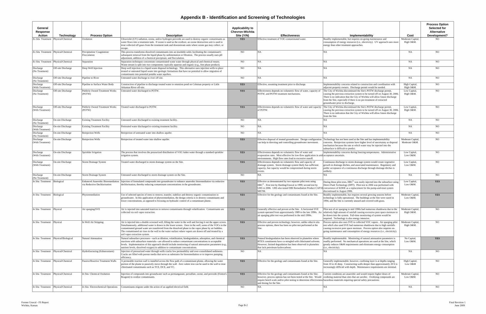
Appendix B - Identification and Screening of Technologies
General Response
Action Technology Process Option Description
Applicability to Chevron-Wichita
Site (Y/N) Effectiveness Implementability Cost
Process Option Selected for Alternative
Development?Ex Situ Treatment Physical/Chemical Oxidation Ultraviolet (UV) radiation, ozone, and/or hydrogen peroxide are used to destroy organic contaminants as
water flows into a treatment tank. If ozone is used as the oxidizer, an ozone destruction unit is used to treat collected off gases from the treatment tank and downstream units where ozone gas may collect, or escape.
YES Effective treatment of VOC-contaminated water. Readily implementable, but requires on-going maintenance and consumption of energy resources (i.e., electricity). UV approach uses more energy than other treatment approaches.
Moderate Capital, High O&M.
NO
Ex Situ Treatment Physical/Chemical Precipitation/ Coagulation/ Flocculation
This process transforms dissolved contaminants into an insoluble solid, facilitating the contaminant's subsequent removal from the liquid phase by sedimentation or filtration. The process usually uses pH adjustment, addition of a chemical precipitant, and flocculation.
NO NA NA NA NO
Ex Situ Treatment Physical/Chemical Separation Separation techniques concentrate contaminated waste water through physical and chemical means. Waste stream is split into two components: typically aqueous and organic (e.g., free phase product).
NO NA NA NA NO
Discharge(No Treatment)
Off-site Discharge Deep Well Injection Deep well injection is a liquid waste disposal technology. This alternative uses injection wells to place treated or untreated liquid waste into geologic formations that have no potential to allow migration of contaminants into potential potable water aquifers.
NO NA NA NA NO
Discharge(No Treatment)
Off-site Discharge Pipeline to River Untreated water discharge to river off site. NO NA NA NA NO
Discharge(With Treatment)
Off-site Discharge Pipeline to Surface Water Body Construction of pipeline to discharge treated water to retention pond on Coleman property or Little Arkansas River off-site.
YES Effective, assuming treatment prior to discharge. Implementability concerns related to construction and coordination with adjacent property owners. Discharge permit would be needed.
High Capital, High O&M.
NO
Discharge(No Treatment)
Off-site Discharge Publicly Owned Treatment Works (POTW)
Untreated water discharged to POTW. YES Effectiveness depends on volumetric flow of water, capacity of POTW, and POTW treatment mechanisms.
The City of Wichita discontinued the Site's POTW discharge permit, causing the previous extraction system to be turned off on August 30, 2006. There is no indication that the City of Wichita will allow future discharge from the Site, especially if there is no pre-treatment of extracted groundwater prior to discharge.
Low Capital,High O&M.
NO
Discharge(With Treatment)
Off-site Discharge Publicly Owned Treatment Works (POTW)
Treated water discharged to POTW. YES Effectiveness depends on volumetric flow of water and capacity of POTW.
The City of Wichita discontinued the Site's POTW discharge permit, causing the previous extraction system to be turned off on August 30, 2006. There is no indication that the City of Wichita will allow future discharge from the Site.
Low Capital,High O&M.
NO
Discharge(No Treatment)
On-site Discharge Existing Treatment Facility Untreated water discharged to existing treatment facility. NO NA NA NA NO
Discharge(With Treatment)
On-site Discharge Existing Treatment Facility Pretreated water discharged to existing treatment facility. NO NA NA NA NO
Discharge(No Treatment)
On-site Discharge Reinjection Wells Reinjection of untreated water into shallow aquifer. NO NA NA NA NO
Discharge(With Treatment)
On-site Discharge Reinjection Wells Reinjection of treated water into shallow aquifer. YES Effective disposal of treated groundwater. Design configuration can help in directing and controlling groundwater movement.
Technology has not been used at the Site and has implementability concerns. Reinjection systems have higher level of uncertainty as disposal mechanism because the rate at which water may be injected into the subsurface is difficult to predict.
Moderate Capital,Moderate O&M.
NO
Discharge(With Treatment)
On-site Discharge Sprinkler Irrigation The process that involves the pressurized distribution of VOC-laden water through a standard sprinkler irrigation system.
YES Effectiveness depends on volumetric flow of water and evaporation rates. Most effective for low-flow application in arid environments. High flow rates lead to excessive runoff.
Implementability concerns during freezing temperatures. Administrative acceptance uncertain.
Low Capital,Low O&M.
NO
Discharge(With Treatment)
On-site Discharge Storm Drainage System Treated water discharged to storm drainage system on the Site. YES Effectiveness depends on volumetric flow and capacity of drainage system. Storm drainage system likely has sufficient capacity, but capacity would be compromised during storm events.
Continuous discharge to storm drainage system would create vegetative growth in drainage ditches, and associated maintenance. Regulatory and public acceptance of a continuous discharge through drainage ditches is unlikely.
Low Capital,Low O&M.
NO
Discharge(No Treatment)
On-site Discharge Storm Drainage System Untreated water discharged to storm drainage system on the Site. NO NA NA NA NO
In Situ Treatment Biological Enhanced Anaerobic Bioremediation via Reductive Dechlorination
Injection of formulated compounds into groundwater to enhance anaerobic bioremediation via reductive dechlorination, thereby reducing contaminant concentrations in the groundwater.
YES Effective as demonstrated by two separate pilot tests using HRC®. First test by Harding/Unocal in 1999; second test by URS in 2006. URS also tested DBI Remediation Product CAP18-METM.
During these pilot tests, HRC® was easily injected into the subsurface using Direct Push Technology (DPT). Pilot test in 2006 was performed with concurrence of KDHE as a replacement for the pump-and-treat system discontinued in August 2006.
Low Capital, Low O&M.
YES
In Situ Treatment Biological Phytoremediation Use of selected species of trees to remove, transfer, stabilize and destroy organic contamination in groundwater. In this application of phytoremediation, the design criteria is to destroy contaminants and lower concentrations, as opposed to focusing on hydraulic control of a contaminant plume.
YES Effective for the geology and contaminants found at the Site. Readily implementable, but requires several growing seasons before technology is fully operational. The buildings at the Site were razed in 1994, and the Site is currently unused and covered with grass.
Moderate Capital, Low O&M.
YES
In Situ Treatment Physical Air sparging/SVE Air is injected into saturated matrices to remove contaminants through volatilization. Contaminants are collected via soil vapor extraction.
YES Generally effective and proven at the Site. A horizontal SVE system operated from approximately 1989 to the late 1990s. An air sparging pilot test was performed in the mid 1990s.
Pilot test of air sparging in mid 1990s had numerous shutdowns due to the relatively high amount of rainfall causing excessive pore space moisture to be drawn into the system. Full-time monitoring of system would be required. Technology is also energy intensive.
Moderate Capital, High O&M.
NO
In Situ Treatment Physical In Well Air Stripping Air is injected into a double screened well, lifting the water in the well and forcing it out the upper screen. Simultaneously, additional water is drawn in the lower screen. Once in the well, some of the VOCs in the contaminated ground water are transferred from the dissolved phase to the vapor phase by air bubbles. The contaminated air rises in the well to the water surface where vapors are drawn off and treated by a soil vapor extraction system.
YES Effective and proven technology; however, unlike other in situ process options, there has been no pilot test performed at the Site.
Process option also uses SVE to collected VOC vapors. Air sparging pilot test which also used SVE had numerous shutdowns due to high rainfalls causing excessive pore space moisture. Process option also requires on-going maintenance and consumption of energy resources (i.e., electricity).
Moderate Capital, High O&M.
NO
In Situ Treatment Physical/Biological Natural Attenuation Natural subsurface processes—such as dilution, volatilization, biodegradation, adsorption, and chemical reactions with subsurface materials—are allowed to reduce contaminant concentrations to acceptable levels. Implementation of this approach should include monitoring of natural attenuation parameters (e.g., nutrient levels, dissolved oxygen) in addition to contaminant concentrations.
YES Natural biodegradation has been observed in plumelets where BTEX constituents have co-mingled with chlorinated solvents. However, limited degradation has been observed in plumelets that lack petroleum hydrocarbons.
Readily implementable. Monitoring of natural attenuation parameters is readily performed. No mechanical operations are used at the Site, which greatly reduces O&M requirements and eliminates energy consumption (i.e., electricity).
No Capital,Low O&M.
YES
In Situ Treatment Physical/Chemical Hydrofracturing (Enhancement) Injection of pressurized water through wells cracks low permeability and over-consolidated sediments. Cracks are filled with porous media that serve as substrates for bioremediation or to improve pumping efficiency.
NO NA NA NA NO
In Situ Treatment Physical/Chemical Passive/Reactive Treatment Walls A permeable reaction wall is installed across the flow path of a contaminant plume, allowing the water portion of the plume to passively move through the wall. Zero valent iron can be used in the wall to treat chlorinated contaminants such as TCE, DCE, and VC.
YES Effective for the geology and contaminants found at the Site. Generally implementable; however, confining layer is at depths ranging from 10 to 45 deep. Constructing walls deeper than approximately 20 ft is increasingly difficult with depth. Maintenance requirements are minimal.
High Capital, Low O&M
NO
In Situ Treatment Physical/Chemical In Situ Chemical Oxidation Injection of compounds into groundwater such as permanganate, persulfate, ozone, and peroxide (Fenton's Reagent) to oxidize contaminants.
YES Effective for the geology and contaminants found at the Site; however, process options has not been tested at the Site. Would require bench scale and/or pilot testing to determine effectiveness and dosing for the Site.
Current conditions are anaerobic and would require higher doses of oxidizing material than sites that are aerobic. Oxidizing compounds are hazardous materials requiring special safety precautions.
Moderate Capital, Low O&M.
NO
In Situ Treatment Physical/Chemical In Situ Electrochemical Operations Contaminants migrate under the action of an applied electrical field. NO NA NA NA NO
Former Unocal - FS ReportWichita, Kansas Page B-2
Final Revision 1June 2009

Appendix C
Computer Modeling of Groundwater Phytoremediation Systems Employing Deep-Rooted Phreatophytic Trees

Battelle Ninth International In Situ and On-Site Bioremediation
Symposium Proceedings, Baltimore, Maryland, May 2007
COMPUTER MODELING OF GROUNDWATER
PHYTOREMEDIATION SYSTEMS EMPLOYING DEEP-ROOTED
PHREATOPHYTIC TREES
Peter M. Thibodeau, Ph.D. ,P.G., P.H. and Ari M. Ferro, Ph.D.
(ENSR, Raleigh, North Carolina)
([email protected]; [email protected])
ABSTRACT: Phytoremediation involves the use of vegetation to remove, degrade,
contain, or sequester contaminants in soils, sediments and groundwater. The use of
stands of deep-rooted trees to control the migration of groundwater contaminant plumes
is an innovative approach that is becoming increasingly popular because these systems
are cost effective, especially for operation and maintenance. Special cultural practices
have been developed to train roots to extend through a relatively thick vadose zone to the
interface between saturated and unsaturated soils. Plant uptake of moisture from the
capillary fringe and shallow groundwater thus creates a capture zone – a specific
thickness of the saturated zone in which groundwater that passes beneath the root-zone
and within the area of their hydraulic influence is used by the trees. Certain dissolved
contaminants that move with the groundwater and enter the capture zone are removed
from the saturated zone. Depending on the chemical class of the contaminants, they
would be removed or sequestered by various phytoremediation processes. A simplified
MODFLOW modeling study was performed to investigate the development of capture
zones as a result of the interactions between the transpiring trees and the groundwater.
The modeling exercise focused on how the thickness of the capture zone varied as a
function of the number of rows of trees and the hydraulic conductivity of the aquifer. As
modeled, plant transpiration resulted in a significant vertical hydraulic influence, and
created an upward driving force to capture groundwater passing through the aquifer. The
modeling results confirmed the notion that the thickness of the capture zone may be
increased by augmenting the number of rows of trees. This relationship was most
pronounced for aquifers with lower hydraulic conductivity. Capture zones were still
created in more conductive aquifers but to a lesser extent, and regardless of the
conductivity of the aquifer, the ability to increase the modeled capture zone thickness
became asymptotic as the number of rows of trees increased. The results provide a useful
tool in designing phytoremediation systems for sites with shallow contaminant plumes.
INTRODUCTION
Trees in the family Salicaceae, the willows and poplars, have been widely used in
groundwater phytoremediation systems (Clinton, et al., 2004; Eberts, et al., 2003; Ferro,
et al., 2001; Ferro, et al., 2003; Green and Hoffnagle, 2004; Hirsh, et al., 2003; Quinn, et
al., 2001, Van Den Bos, 2002; Weaver, et al., 2003). In many cases, the objectives of
the systems have been to hydraulically control the migration of groundwater plumes
containing dissolved organic chemical contaminants. The rapid growth rate, high rates of
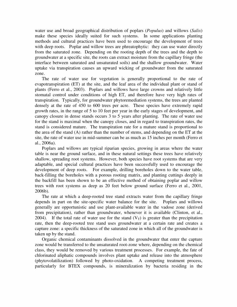
water use and broad geographical distribution of poplars (Populus) and willows (Salix)
make these species ideally suited for such systems. In some applications planting
methods and cultural practices have been used to encourage the development of trees
with deep roots. Poplar and willow trees are phreatophytic: they can use water directly
from the saturated zone. Depending on the rooting depth of the trees and the depth to
groundwater at a specific site, the roots can extract moisture from the capillary fringe (the
interface between saturated and unsaturated soils) and the shallow groundwater. Water
uptake via transpiration causes an upward wicking of groundwater from the saturated
zone.
The rate of water use for vegetation is generally proportional to the rate of
evapotranspiration (ET) at the site, and the leaf area of the individual plant or stand of
plants (Ferro et al., 2003). Poplars and willows have large crowns and relatively little
stomatal control under conditions of high ET, and therefore have very high rates of
transpiration. Typically, for groundwater phytoremediation systems, the trees are planted
densely at the rate of 450 to 600 trees per acre. These species have extremely rapid
growth rates, in the range of 5 to 10 feet per year in the early stages of development, and
canopy closure in dense stands occurs 3 to 5 years after planting. The rate of water use
for the stand is maximal when the canopy closes, and in regard to transpiration rates, the
stand is considered mature. The transpiration rate for a mature stand is proportional to
the area of the stand (A) rather than the number of stems, and depending on the ET at the
site, the rate of water use in mid-summer can be as much as 15 inches per month (Ferro et
al., 2006a).
Poplars and willows are typical riparian species, growing in areas where the water
table is near the ground surface, and in these natural settings these trees have relatively
shallow, spreading root systems. However, both species have root systems that are very
adaptable, and special cultural practices have been successfully used to encourage the
development of deep roots. For example, drilling boreholes down to the water table,
back-filling the boreholes with a porous rooting matrix, and planting cuttings deeply in
the backfill has been shown to be an effective method of obtaining poplar and willow
trees with root systems as deep as 20 feet below ground surface (Ferro et al., 2001,
2006b).
The rate at which a deep-rooted tree stand extracts water from the capillary fringe
depends in part on the site-specific water balance for the site. Poplars and willows
generally are opportunistic and use plant-available water in the vadose zone (derived
from precipitation), rather than groundwater, whenever it is available (Clinton, et al.,
2004). If the total rate of water use for the stand (VT) is greater than the precipitation
rate, then the deep-rooted tree stand uses groundwater at a certain rate and creates a
capture zone: a specific thickness of the saturated zone in which all of the groundwater is
taken up by the stand.
Organic chemical contaminants dissolved in the groundwater that enter the capture
zone would be transferred to the unsaturated root-zone where, depending on the chemical
class, they would be removed by various treatment processes. For example, the fate of
chlorinated aliphatic compounds involves plant uptake and release into the atmosphere
(phytovolatilization) followed by photo-oxidation. A competing treatment process,
particularly for BTEX compounds, is mineralization by bacteria residing in the
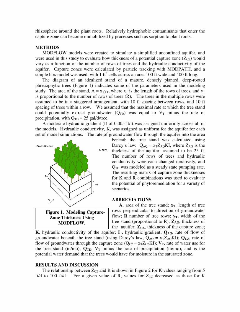
rhizosphere around the plant roots. Relatively hydrophobic contaminants that enter the
capture zone can become immobilized by processes such as sorption to plant roots.
METHODS
MODFLOW models were created to simulate a simplified unconfined aquifer, and
were used in this study to evaluate how thickness of a potential capture zone (ZCZ) would
vary as a function of the number of rows of trees and the hydraulic conductivity of the
aquifer. Capture zones were calculated by particle tracking with MODPATH, and a
simple box model was used, with 1 ft3 cells across an area 100 ft wide and 400 ft long.
The diagram of an idealized stand of a mature, densely planted, deep-rooted
phreaophytic trees (Figure 1) indicates some of the parameters used in the modeling
study. The area of the stand, A = xTyT, where xT is the length of the rows of trees, and yT
is proportional to the number of rows of trees (R). The trees in the multiple rows were
assumed to be in a staggered arrangement, with 10 ft spacing between rows, and 10 ft
spacing of trees within a row. We assumed that the maximal rate at which the tree stand
could potentially extract groundwater (QTD) was equal to VT minus the rate of
precipitation, with QTD = 25 gal/d/tree.
A moderate hydraulic gradient (I) of 0.005 ft/ft was assigned uniformly across all of
the models. Hydraulic conductivity, K, was assigned as uniform for the aquifer for each
set of model simulations. The rate of groundwater flow through the aquifer into the area
beneath the tree stand was calculated using
Darcy’s law: QAQ = xTZAQKI, where ZAQ is the
thickness of the aquifer, assumed to be 25 ft.
The number of rows of trees and hydraulic
conductivity were each changed iteratively, and
QTD was modeled as a steady state pumping rate.
The resulting matrix of capture zone thicknesses
for K and R combinations was used to evaluate
the potential of phytoremediation for a variety of
scenarios.
ABBREVIATIONS
A, area of the tree stand; xT, length of tree
rows perpendicular to direction of groundwater
flow; R number of tree rows; yT, width of the
tree stand (proportional to R); ZAQ, thickness of
the aquifer; ZCZ, thickness of the capture zone;
K, hydraulic conductivity of the aquifer; I , hydraulic gradient; QAQ, rate of flow of
groundwater beneath the tree stand (using Darcy’s law, QAQ = xTZAQKI); QCZ, rate of
flow of groundwater through the capture zone (QCZ = xTZCZKI); VT, rate of water use for
the tree stand (in/mo); QTD, VT minus the rate of precipitation (in/mo), and is the
potential water demand that the trees would have for moisture in the saturated zone.
RESULTS AND DISCUSSION
The relationship between ZCZ and R is shown in Figure 2 for K values ranging from 5
ft/d to 100 ft/d. For a given value of R, values for ZCZ decreased as those for K
Figure 1. Modeling Capture-
Zone Thickness Using
MODFLOW.

increased. For example, with R = 8, the approximate values for ZCZ were 24 ft, 13 ft, and
6 ft, as values for K were allowed to range from 5 ft/d, 20 ft/d, and 80 ft/d, respectively.
Thus, the modeling results suggested that as the horizontal vector of groundwater flow
increased, it tended to overcome the vertical influence of QTD, and the capture zone
became thinner.
0
5
10
15
20
25
30
0 2 4 6 8 10 12 14 16 18 20
Number of Rows of Trees
Th
ick
ne
ss
of
Ca
ptu
re Z
on
e,
Zc
z
5 ft/day 10 ft/day 20 ft/day 40 ft/day 60 ft/day 80 ft/day 100 ft/day
Figure 2. Capture-Zone Thickness. Thickness of the capture zone (Zcz) is a
function of the number of rows of trees (R) and the hydraulic conductivity of the
aquifer.
The curves in Figure 2 became asymptotic as values for R increased. With K = 5 ft/d,
for example, the value of ZCZ increased steadily as the value of R ranged from 1 to 8.
However, further increases in R had little effect on ZCZ. This result suggested that the
upward driving forces created by QTD had been attained, and any further increase would
be overcome by horizontal flow forces at some depth in the aquifer.
While values for ZCZ were substantial under certain sets of modeled conditions,
groundwater uptake by stands of deep-rooted trees had relatively little effect on the water
table elevation in the area of the tree stand (i.e., drawdown, or changes in I). For
example, at K = 5 ft/d and R = 8, ZCZ was approximately 24 ft, yet the decrease in water
table elevation was only a few inches. As ZCZ increased as a function of R, the rate of
groundwater flow through the capture zone (QCZ) increased, but because changes in I
were minimal, this increase was mainly due to the increase in ZCZ.
The relationship between QTD and ZCZ was analyzed previously using both analytical
calculations and computer simulations (Ferro et al., 2003). These analyses suggested that
QTD induced hydraulic stress in the groundwater flow field, and that the QTD required to
create a capture zone with thickness ZCZ hypothetically would be approximately 2 QCZ

(Ferro, et al. 2003). The current MODFLOW modeling results shown in Figure 3
indicated that the hypothetical relationship QTD = 2 QCZ may be useful for the purposes of
designing groundwater phytoremediation systems.
0
20
40
60
80
100
120
0 40 80 120 160 200 240
Qc
z (
ft3/d
)
K=5
K=10
K=20
K=40
K=60
K=80
K=100
QTD=2QCZ
QTD (ft3/d)
FIGURE 3. Relationship between QCZ and QTD. The relationship between QCZ
(the rate of groundwater flow through the capture zone) and QTD (the potential
groundwater demand by the trees) is shown for a range of K values. The values for
R for the different QTD values, and the hypothetical QTD = 2 QCZ relationship are
also shown.
The relationship between QCZ and QTD is shown in Figure 3 for K values ranging
from 5 ft/d to 100 ft/d. Also shown in Figure 3 are the values of R for the different QTD
values, as well as the hypothetical QTD = 2 QCZ relationship. The results for K = 60 ft/d
matched the hypothetical relationship most closely, with the results for the aquifers with
higher K values falling above the line, and those with lower K values falling below the
line. However, the ratio of QTD to QCZ was variable and decreased with lower K values.
This result suggested that trees plumbed into aquifers with low K values would still have
a substantial demand for plant-available moisture from the unsaturated zone.
The use of tracer tests to demonstrate the hydraulic control of groundwater in a deep-
rooted tree system was discussed previously (Ferro, et al., 2003). The results from the
current modeling study appear to be useful for predicting the outcome from tracer tests.
For example, the modeling results suggested that for an aquifer with K = 5 ft/d, a system
with four rows of trees could create a capture zone approximately 18 ft thick (Figure 2).
Thus, a non-reactive solute such as bromide would be taken up if injected into the
groundwater immediately up-gradient of a deep-rooted tree in such a system. However,
1 4 8 12 16 20 R, rows of trees

based on the modeling results shown in Figure 3, much of the moisture taken up by the
tree would be derived from the unsaturated zone, thus increasing the time required for the
uptake of the tracer.
REFERENCES
Clinton, B. D., J. M. Vose, D. A. Vroblesky, and G. J. Harvey. 2004. “Determination of
the Relative Uptake of Ground vs. Surface Water by Poplus deltoides During
Phytoremediation.” International Journal of Phytoremediation. 6(3): 239-252.
Eberts, S. M., G. J. Harvey, S. A. Jones, and S. W. Beckman. 2003. “Multiple-Process
Assessment for a Chlorinated-Solvent Plume.” In S. C. McCutcheon and J. L.
Schnoor (Eds.), Phytoremediation: Transformation and Control of Contaminants, pp.
589-633. John Wiley & Sons, Inc.
Ferro, A., J. Chard, R. Kjelgren, B. Chard, D. Turner, and T. Montague. 2001.
“Groundwater Capture Using Hybrid Poplar Trees: Evaluation of a System in Ogden,
Utah.” International Journal of Phytoremediation. 3(1): 87-104.
Ferro, A., M. Gefell, R. Kjelgren, D. S. Lipson, N. Zollinger, and S. Jackson. 2003.
“Maintaining Hydraulic Control Using Deep Rooted Tree Systems.” In D. Tsao (Ed.),
Advances in Biochemical Engineering/Biotechnology, Volume 78, pp. 125-156.
Springer-Verlag, Berlin Heidelberg, Germany.
Ferro, A. M., K. Lumino, and B. Thompson. 2006a. Phytoremediation Reduces
Mechanical Pumping and Ex-Situ Treatment of Groundwater. Technology News and
Trends EPA 542/N-06/003. U.S. Environmental Protection Agency, Office of Solid
Waste and Emergency Response.
Ferro, A. M., J. Cassada, B. Berra, and D. Tsao. 2006b. Phytoremediation of TPH-
Contaminated Groundwater. 22nd
Annual International Conf. on Soils, Sediments,
and Water, University of Massachusetts, Amherst, MA. October 2006.
Green, C., and A. Hoffnagle. 2004. Phytoremediation Field Studies Database for
Chlorinated Solvents, Pesticides, Explosives, and Metals. USEPA Office of
Superfund Remediation and Technology Innovation, Washington, D.C.
Hirsh, S. R., H. R. Compton, D. H. Matey, J. G. Wrobel, and W. H. Schneider. 2003.
“Five-year Pilot Study: Aberdeen Proving Ground, Maryland.” In S. C. McCutcheon
and J. L. Schnoor (Eds.), Phytoremediation: Transformation and Control of
Contaminants, pp. 635-659. John Wiley & Sons, Inc.
Quinn, J. J., M. C. Negri, R. R. Hinchman, L. P. Moos, J. B. Wozniak, and E. G. Gatliff.
2001. “Predicting the Effect of Deep-Rooted Hybrid Poplars on the Groundwater
Flow System at a Large-Scale Phytoremediation Site.” International Journal of
Phytoremediation. 3(1): 41-604.
Van Den Bos, A. 2002. Phytoremediation of Volatile Organic Compounds in
Groundwater: Case Studies in Plume Control. USEPA Office of Solid Waste and
Emergency Response, Technology Innovation Office, Washington, D.C.
Weaver, J. W., S. C. McCutcheon, and S. L. Hutchinson. 2003. “Hydrologic Feasibility
Assessment and Design in Phytoremediation.” In S. C. McCutcheon and J. L.
Schnoor (Eds.), Phytoremediation: Transformation and Control of Contaminants, pp.
695-716. John Wiley & Sons, Inc.
Appendix D
Calculations for Predicted Chemicals of Concern Concentration Reduction and Reinjection Frequency
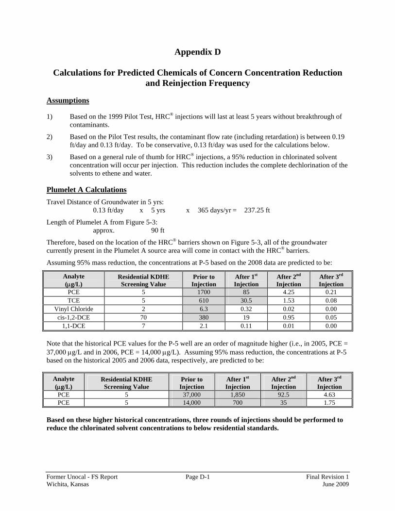
Former Unocal - FS Report Page D-1 Final Revision 1 Wichita, Kansas June 2009
Appendix D
Calculations for Predicted Chemicals of Concern Concentration Reduction and Reinjection Frequency
Assumptions
1) Based on the 1999 Pilot Test, HRC® injections will last at least 5 years without breakthrough of contaminants.
2) Based on the Pilot Test results, the contaminant flow rate (including retardation) is between 0.19 ft/day and 0.13 ft/day. To be conservative, 0.13 ft/day was used for the calculations below.
3) Based on a general rule of thumb for HRC® injections, a 95% reduction in chlorinated solvent concentration will occur per injection. This reduction includes the complete dechlorination of the solvents to ethene and water.
Plumelet A Calculations Travel Distance of Groundwater in 5 yrs: 0.13 ft/day x 5 yrs x 365 days/yr = 237.25 ft
Length of Plumelet A from Figure 5-3: approx. 90 ft
Therefore, based on the location of the HRC® barriers shown on Figure 5-3, all of the groundwater currently present in the Plumelet A source area will come in contact with the HRC® barriers.
Assuming 95% mass reduction, the concentrations at P-5 based on the 2008 data are predicted to be:
Analyte (μg/L)
Residential KDHE Screening Value
Prior to Injection
After 1st Injection
After 2nd Injection
After 3rd Injection
PCE 5 1700 85 4.25 0.21 TCE 5 610 30.5 1.53 0.08
Vinyl Chloride 2 6.3 0.32 0.02 0.00 cis-1,2-DCE 70 380 19 0.95 0.05
1,1-DCE 7 2.1 0.11 0.01 0.00
Note that the historical PCE values for the P-5 well are an order of magnitude higher (i.e., in 2005, PCE = 37,000 μg/L and in 2006, PCE = 14,000 μg/L). Assuming 95% mass reduction, the concentrations at P-5 based on the historical 2005 and 2006 data, respectively, are predicted to be:
Analyte (μg/L)
Residential KDHE Screening Value
Prior to Injection
After 1st Injection
After 2nd Injection
After 3rd Injection
PCE 5 37,000 1,850 92.5 4.63 PCE 5 14,000 700 35 1.75
Based on these higher historical concentrations, three rounds of injections should be performed to reduce the chlorinated solvent concentrations to below residential standards.
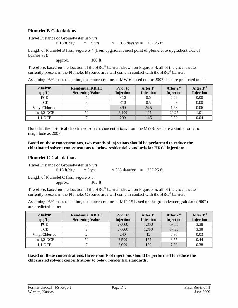
Former Unocal - FS Report Page D-2 Final Revision 1 Wichita, Kansas June 2009
Plumelet B Calculations Travel Distance of Groundwater in 5 yrs: 0.13 ft/day x 5 yrs x 365 days/yr = 237.25 ft
Length of Plumelet B from Figure 5-4 (from upgradient most point of plumelet to upgradient side of Barrier #3): approx. 180 ft
Therefore, based on the location of the HRC® barriers shown on Figure 5-4, all of the groundwater currently present in the Plumelet B source area will come in contact with the HRC® barriers.
Assuming 95% mass reduction, the concentrations at MW-6 based on the 2007 data are predicted to be:
Analyte (μg/L)
Residential KDHE Screening Value
Prior to Injection
After 1st Injection
After 2nd Injection
After 3rd Injection
PCE 5 <10 0.5 0.03 0.00 TCE 5 <10 0.5 0.03 0.00
Vinyl Chloride 2 490 24.5 1.23 0.06 cis-1,2-DCE 70 8,100 405 20.25 1.01
1,1-DCE 7 290 14.5 0.73 0.04
Note that the historical chlorinated solvent concentrations from the MW-6 well are a similar order of magnitude as 2007.
Based on these concentrations, two rounds of injections should be performed to reduce the chlorinated solvent concentrations to below residential standards for HRC® injections.
Plumelet C Calculations Travel Distance of Groundwater in 5 yrs: 0.13 ft/day x 5 yrs x 365 days/yr = 237.25 ft
Length of Plumelet C from Figure 5-5: approx. 105 ft
Therefore, based on the location of the HRC® barriers shown on Figure 5-5, all of the groundwater currently present in the Plumelet C source area will come in contact with the HRC® barriers.
Assuming 95% mass reduction, the concentrations at MIP-15 based on the groundwater grab data (2007) are predicted to be:
Analyte (μg/L)
Residential KDHE Screening Value
Prior to Injection
After 1st Injection
After 2nd Injection
After 3rd Injection
PCE 5 27,000 1,350 67.50 3.38 TCE 5 27,000 1,350 67.50 3.38
Vinyl Chloride 2 240 12 0.60 0.03 cis-1,2-DCE 70 3,500 175 8.75 0.44
1,1-DCE 7 3,000 150 7.50 0.38
Based on these concentrations, three rounds of injections should be performed to reduce the chlorinated solvent concentrations to below residential standards.
Appendix E
Identification of ARARS
Former Unocal - FS Report Page E-1 Final Revision 1 Wichita, Kansas June 2009
Appendix E
Identification of ARARs
The Kansas Department of Health and Environment (KDHE) and Unocal signed a Consent Order on March 23, 1992 that outlined provisions for a Remedial Investigation (RI) and FS to be conducted at the Site and for interim remedial actions to be implemented, as needed (Case Number 91-E-206). Attachment I of the Consent Order (The Scope of Work for a Remedial Investigation [RI]/Feasibility Study [FS]) specifies that all work (on the RI/FS) shall be in accordance with the Comprehensive Environmental Response, Compensation, and Liability Act (CERCLA) of 1980, the Superfund Amendments and Reauthorization Act (SARA) of 1986, the National Oil and Hazardous Substances Pollution Contingency Plan (NCP) (Title 40 of the Code of Federal Regulations [CFR], Part 300), and associated EPA guidance documents.
Accordingly, remedial alternatives are developed and evaluated in accordance with the aforementioned documents, including the use of the nine CERCLA evaluation criteria. Compliance with applicable or relevant and appropriate requirements (ARARs) is one of nine criteria for remedial alternative evaluations [40 CFR 430(e)(9)(iii)(B)]. This appendix identifies the ARARs that were included in the compliance evaluation.
The ARARs identification process was conducted in accordance with the following:
• CERCLA, Section 121(d)(2)(A);
• Title 40 Code of Federal Regulations Part 300 [specifically, Sections 300.5 and 300.400(g)];
• EPA, RCRA, Superfund & EPCRA Hotline Training Module, EPA540-R-98-020, June 1998;
• EPA, ARARs Q’s & A’s: General Policy, RCRA, CWA, SDWA, Post-ROD Information, and Contingent Waivers, Publication 9234.2-01/FS-A, July 1991;
• EPA, RCRA ARARs: Focus on Closure Requirements, Directive 9234.2-04FS, October 1989;
• EPA, CERCLA Compliance with Other Laws Manual: Part II. Clean Air Act and Other Environmental Statutes and State Requirements, EPA/540/G-89/009, August 1989;
• EPA, Guidance for Conducting Remedial Investigations and Feasibility Studies Under CERCLA, EPA/540/G-89/004, October 1988; and
• EPA, CERCLA Compliance with Other Laws Manual: Interim Final, EPA/540/G-89/006, August 1988.
The terms applicable requirements and relevant and appropriate requirements are defined in 40 CFR Section 300.5 as follows:

Former Unocal - FS Report Page E-2 Final Revision 1 Wichita, Kansas June 2009
Applicable requirements means those cleanup standards, standards of control, and other substantive requirements, criteria, or limitations promulgated under federal environmental or state environmental or facility siting laws that specifically address a hazardous substance, pollutant, contaminant, remedial action, location, or other circumstance found at a CERCLA site. Only those state standards that are identified by a state in a timely manner and that are more stringent than federal requirements may be applicable.
Relevant and appropriate requirements means those cleanup standards, standards of control, and other substantive requirements, criteria, or limitations promulgated under federal environmental or state environmental or facility siting laws that, while not “applicable” to a hazardous substance, pollutant, contaminant, remedial action, location, or other circumstance at a CERCLA site, address problems or situations sufficiently similar to those encountered at the CERCLA site that their use is well suited to the particular site. Only those state standards that are identified in a timely manner and are more stringent than federal requirements may be relevant and appropriate.
ARARs may be federal, state, or local requirements. The requirement must be legally enforceable for evaluation as a potential ARAR. Guidelines and voluntary standards are not legally enforceable and are evaluated separately as potential “to be considered” guidelines (TBCs) [40 CFR 300.400(g)(3)]. TBCs are not legally enforceable, but become enforceable when included in an approved record of decision (ROD). Identification of TBCs is not mandatory, but are typically identified when useful in developing CERCLA remedies (e.g., when ARARs do not exist or are not fully protective).
In making a determination of whether a particular requirement under an environmental law may be applicable or relevant and appropriate, a two-part analysis that is based on the site-specific conditions was performed in accordance with 40 CFR 300.400(g). The first part of the analysis entails making a determination of whether the requirement is applicable. If the requirement is applicable, it is an ARAR and no further analysis is needed. If a determination is made that the requirement is not applicable, then a determination of whether the requirement is relevant and appropriate must be made. EPA (August 1988) provides substantial guidance in determining whether requirements are relevant and appropriate. The basic considerations are whether the requirement (1) regulates or addresses problems or situations sufficiently similar to those encountered at the CERCLA site (i.e., relevance), and (2) is appropriate to the circumstances of the release or threatened release, such that its use is well suited to the particular site. If the requirement is relevant and appropriate, it is an ARAR.
ARARs are typically divided into three categories: chemical, location, and action.
• Chemical-specific ARARs are typically risk-based standards, requirements, criteria, or limitations which when applied to the site yield numerical limitations for acceptable amounts of a particular chemical that may be present in an environmental media.
• Location-specific ARARs are typically standards, requirements, criteria, or limitations that are placed on activities conducted at certain locations due to the unique nature of the location.
Former Unocal - FS Report Page E-3 Final Revision 1 Wichita, Kansas June 2009
• Action-specific ARAR are typically standards, requirements, criteria, or limitations that are placed on remedial actions that affect hazardous substances.
Table E-1 summarizes the results of the identification process. Regulations that were evaluated but determined to not be ARARs are also presented in this table. This table was prepared for the purposes of this feasibility study. More detailed citations and identification of specific requirements will be performed for the selected remedy when identified in the ROD.
For off-site actions, both substantive and administrative requirements are considered potential ARARs. CERCLA Section 121(e) exempts on-site actions from administrative requirements; therefore, only substantive requirements are considered potential ARARs for on-site actions. A discussion of substantive versus administrative requirements is found in CERCLA Compliance with Other Laws Manual (EPA, August 1988), Section 1.2.2.1:
Substantive requirements are those requirements that pertain directly to actions or conditions in the environment. Examples of substantive requirements include quantitative health- or risk-based restrictions upon exposure to types of hazardous substances (e.g., MCLs establishing drinking water standards for particular contaminants), technology-based requirements for actions taken upon hazardous substances (e.g., incinerator standards requiring particular destruction and removal efficiency), and restrictions upon activities in certain special locations (e.g., standards prohibiting certain types of facilities in floodplains).
Administrative requirements are those mechanisms that facilitate the implementation of the substantive requirements of a statute or regulation. Administrative requirements include the approval of, or consultation with administrative bodies, consultation, issuance of permits, documentation, reporting, recordkeeping, and enforcement. In general administrative requirements prescribe methods and procedures by which substantive requirements are made effective for purposes of a particular environmental or public health program.
The detailed analysis of alternatives evaluates each alternative’s ability to comply with the federal and state ARARs identified in Table E-1. The selected remedy in the ROD must satisfy all ARARs, unless one or more of the following six waivers are obtained [40 CFR Section 300.430(f)(1)(ii)(C)]:
1. The alternative is an interim measure and will become part of a total remedial action that will attain the applicable or relevant and appropriate federal or state requirement;
2. Compliance with the requirement will result in greater risk to human health and the environment than other alternatives;
3. Compliance with the requirement is technically impracticable from an engineering perspective;
4. The alternative will attain a standard of performance that is equivalent to that required under the otherwise applicable standard, requirement, or limitation through use of another method or approach;
Former Unocal - FS Report Page E-4 Final Revision 1 Wichita, Kansas June 2009
5. With respect to a state requirement, the state has not consistently applied, or demonstrated the intention to consistently apply, the promulgated requirement in similar circumstances at other remedial actions within the state; or
6. For Fund-financed response actions only, an alternative that attains the ARAR will not provide a balance between the need for protection of human health and the environment at the site and the availability of Fund monies to respond to other sites that may present a threat to human health and the environment.
The ARARs identified in Table E-1 were reviewed to determine whether any of the six waivers above are warranted. No waivers to these ARARs are warranted.

Table E-1. Identification of ARARs and TBCs
Type Scope Citation Description Overview of Requirements Primary Basis for Determination
Determination of Applicable/ Relevant and Appropriate
Chemical Federal 40 CFR Part 129 (CWA - 33 USC §§ 1251-1376)
Toxic Pollutant Effluent
Standards
This part establishes surface water effluent standards for the following toxic pollutants: aldrin/dieldrin, DDT, DDE, DDD, endrin, toxaphene, benzidine, and PCBs.
These toxic pollutants were not identified as COCs.No/No
Chemical Federal 40 CFR Section 131.36 (CWA - 33
USC §§ 1251-1376)
Surface Water Quality Criteria
for Priority Toxic Pollutants
This section establishes freshwater ambient water quality standards for 126 priority pollutants, including metals, VOCs, SVOCs, PAHs, pesticides, PCBs, and dioxins. This section only applies to those States not in compliance with the Clean Water Act Section 303(c)(2)(B).
There are no impacts to surface water on the Site proper.
No/No
Chemical Federal 40 CFR Part 141 (SDWA - 42 USC
§ 300)
National Primary Drinking Water
Standards
This part specifies maximum contaminant levels (MCLs) and MCL Goals (MCLGs), which are used as drinking water standards for public water systems. MCLs are specified for a wide range of organic and inorganic analytes. Of particular note are the MCLs for PCE (5 ug/L), TCE (5 ug/L), cis-1,2-DCE (70 ug/L), vinyl chloride (2 ug/L), and benzene (5 ug/L).
Groundwater is not a current source of drinking water; accordingly, drinking water standards are not applicable. However, contaminated groundwater is a potential source of drinking water and has the potential to migrate to a current source of drinking water. Accordingly, non-zero MCLs and MCLs are considered relevant and appropriate.
No/Yes
Chemical Federal 40 CFR Part 143 (SDWA - 42 USC
§ 300)
National Secondary
Drinking Water Standards
This part specifies secondary maximum contaminant levels (MCLs) for public water systems. These regulations control contaminants in drinking water that primarily affect the aesthetic qualities relating to the public acceptance of drinking water (e.g., total dissolved solids, iron, manganese, pH).
Site groundwater is not a current source of drinking water; accordingly, drinking water standards are not applicable. Secondary MCLs address aesthetic qualities and are not risk-based. Accordingly, these standards are not considered relevant and appropriate.
No/No
Chemical State KAR Title 28, Article 15
Kansas Drinking Water Standards
Establish maximum contaminant levels (MCLs) for Kansas. The federal MCLs specified in 40 CFR 141 are generally adopted by reference, including those for organic contaminants.
Groundwater is not a current source of drinking water; accordingly, drinking water standards are not applicable. However, contaminated groundwater is a potential source of drinking water and has the potential to migrate to a current source of drinking water. Accordingly, non-zero MCLs and MCLs are considered relevant and appropriate.
No/Yes
Chemical State KAR § 28-16-28 Kansas Surface Water Quality
Criteria
Provide surface water quality standards, surface water quality antidegration policy, surface water classification and use policy, and surface water quality criteria.
The Site Proper does not have impacted surface water.No/No
Chemical State Risk-Based Standards for Kansas RSK Manual - 4th Version, June
2007
Kansas Risk-Based Standards
Describes process for establishing chemical-specific and site-specific clenaup goals for soil and groundwater that are protective of human health and the environment.
These risk-based standards have been widely used at the Site Proper during the investigation. No formal risk assessment was developed that provides an established calculation methodology specific to this site. Accordingly, this manual provides the most appropriate framework under which to calculate risk-based standards.
TBC
Former Unocal - FS ReportWichita, Kansas Page E-5
Final Revision 1June 2009
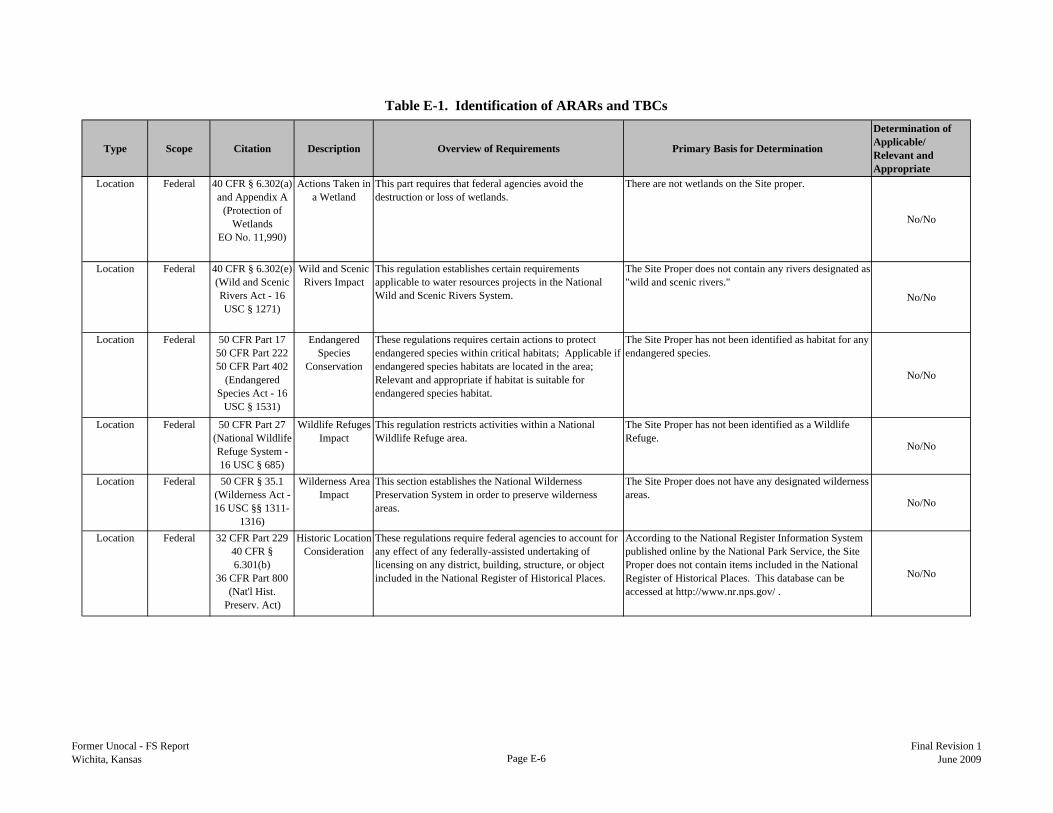
Table E-1. Identification of ARARs and TBCs
Type Scope Citation Description Overview of Requirements Primary Basis for Determination
Determination of Applicable/ Relevant and Appropriate
Location Federal 40 CFR § 6.302(a) and Appendix A
(Protection of Wetlands
EO No. 11,990)
Actions Taken in a Wetland
This part requires that federal agencies avoid the destruction or loss of wetlands.
There are not wetlands on the Site proper.
No/No
Location Federal 40 CFR § 6.302(e) (Wild and Scenic Rivers Act - 16 USC § 1271)
Wild and Scenic Rivers Impact
This regulation establishes certain requirements applicable to water resources projects in the National Wild and Scenic Rivers System.
The Site Proper does not contain any rivers designated as "wild and scenic rivers."
No/No
Location Federal 50 CFR Part 17 50 CFR Part 222 50 CFR Part 402
(Endangered Species Act - 16
USC § 1531)
Endangered Species
Conservation
These regulations requires certain actions to protect endangered species within critical habitats; Applicable if endangered species habitats are located in the area; Relevant and appropriate if habitat is suitable for endangered species habitat.
The Site Proper has not been identified as habitat for any endangered species.
No/No
Location Federal 50 CFR Part 27 (National Wildlife Refuge System - 16 USC § 685)
Wildlife Refuges Impact
This regulation restricts activities within a National Wildlife Refuge area.
The Site Proper has not been identified as a Wildlife Refuge.
No/No
Location Federal 50 CFR § 35.1 (Wilderness Act - 16 USC §§ 1311-
1316)
Wilderness Area Impact
This section establishes the National Wilderness Preservation System in order to preserve wilderness areas.
The Site Proper does not have any designated wilderness areas.
No/No
Location Federal 32 CFR Part 229 40 CFR § 6.301(b)
36 CFR Part 800 (Nat'l Hist.
Preserv. Act)
Historic Location Consideration
These regulations require federal agencies to account for any effect of any federally-assisted undertaking of licensing on any district, building, structure, or object included in the National Register of Historical Places.
According to the National Register Information System published online by the National Park Service, the Site Proper does not contain items included in the National Register of Historical Places. This database can be accessed at http://www.nr.nps.gov/ .
No/No
Former Unocal - FS ReportWichita, Kansas Page E-6
Final Revision 1June 2009

Table E-1. Identification of ARARs and TBCs
Type Scope Citation Description Overview of Requirements Primary Basis for Determination
Determination of Applicable/ Relevant and Appropriate
Location Federal 33 CFR Parts 320-330
(Rivers and Harbors Act of
1899 - 33 USC § 401-413)
Navigation and Navigable
Waters
These guidelines establish requirements for activities affecting waters of the U.S. and navigable waters (e.g,. discharge of dredged material into waters of the U.S.). "Waters of the U.S." is defined in 33 CFR Section 328.3. This definition includes "waters such as intrastate lakes, rivers, streams (including intermittent streams), mudflats, sandflats, wetlands, sloughs, prairie potholes, wet meadows, playa lakes, or natural ponds, the use, degradation or destruction of which could affect interstate or foreign commerce..." Navigable waters of the United States are those waters that are subject to the ebb and flow of the tide and/or are presently used, or have been used in the past, or may be susceptible for use to transport interstate or foreign commerce (33 CFR Section 329.4).
The Site Proper does not have any navigable waters.
No/No
Location Federal 40 CFR Part 230-233
CWA - 33 USC § 1251 et seq)
Disposal Sites for Dredged or Fill
Material
The purpose of these Guidelines is to restore and maintain the chemical, physical, and biological integrity of waters of the United States through the control of discharges of dredged or fill material. Fundamental to these Guidelines is the precept that dredged or fill material should not be discharged into the aquatic ecosystem, unless it can be demonstrated that such a discharge will not have an unacceptable adverse impact either individually or in combination with known and/or probable impacts of other activities affecting the ecosystems of concern (40 CFR Section 230.1).
The Site Proper does not have any surface water supporting an aquatic ecosystem.
No/No
Location Federal 13 USC § 1700 (Federal Land
Policy and Management Act - 13 USC § 1700)
Federal Land Management
These requirements relate to the use of public lands (e.g., rights-of-way regulation, land use planning, and land acquisition and appropriation of waters on public lands). According to the Federal Land Policy and Management Act, the term “public lands” describes any land and interest in land owned by the United States within several States and administered by the Secretary of the Interior through the Bureau of Land Management.
The Site Proper is nor a federal land, nor a public land administered by the Bureau of Land Management.
No/No
Location Federal 16 USC §§ 1451-1464
Coastal Zone Management
This guideline prohibits federal agencies from taking activities not in agreement with the state's approved coastal zone management program.
The Site Proper does not have any Coastal Zones.No/No
Former Unocal - FS ReportWichita, Kansas Page E-7
Final Revision 1June 2009
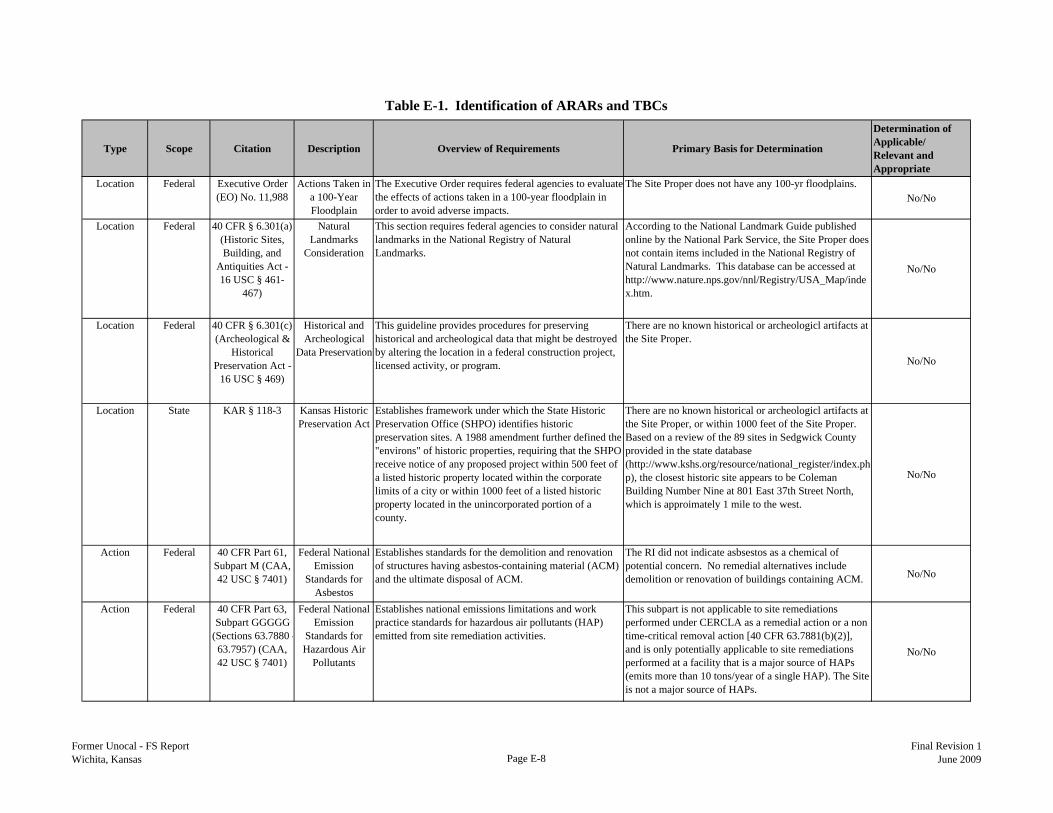
Table E-1. Identification of ARARs and TBCs
Type Scope Citation Description Overview of Requirements Primary Basis for Determination
Determination of Applicable/ Relevant and Appropriate
Location Federal Executive Order (EO) No. 11,988
Actions Taken in a 100-Year Floodplain
The Executive Order requires federal agencies to evaluate the effects of actions taken in a 100-year floodplain in order to avoid adverse impacts.
The Site Proper does not have any 100-yr floodplains.No/No
Location Federal 40 CFR § 6.301(a) (Historic Sites, Building, and
Antiquities Act - 16 USC § 461-
467)
Natural Landmarks
Consideration
This section requires federal agencies to consider natural landmarks in the National Registry of Natural Landmarks.
According to the National Landmark Guide published online by the National Park Service, the Site Proper does not contain items included in the National Registry of Natural Landmarks. This database can be accessed at http://www.nature.nps.gov/nnl/Registry/USA_Map/index.htm.
No/No
Location Federal 40 CFR § 6.301(c)(Archeological &
Historical Preservation Act -
16 USC § 469)
Historical and Archeological
Data Preservation
This guideline provides procedures for preserving historical and archeological data that might be destroyed by altering the location in a federal construction project, licensed activity, or program.
There are no known historical or archeologicl artifacts at the Site Proper.
No/No
Location State KAR § 118-3 Kansas Historic Preservation Act
Establishes framework under which the State Historic Preservation Office (SHPO) identifies historic preservation sites. A 1988 amendment further defined the "environs" of historic properties, requiring that the SHPO receive notice of any proposed project within 500 feet of a listed historic property located within the corporate limits of a city or within 1000 feet of a listed historic property located in the unincorporated portion of a county.
There are no known historical or archeologicl artifacts at the Site Proper, or within 1000 feet of the Site Proper. Based on a review of the 89 sites in Sedgwick County provided in the state database (http://www.kshs.org/resource/national_register/index.php), the closest historic site appears to be Coleman Building Number Nine at 801 East 37th Street North, which is approimately 1 mile to the west.
No/No
Action Federal 40 CFR Part 61, Subpart M (CAA, 42 USC § 7401)
Federal National Emission
Standards for Asbestos
Establishes standards for the demolition and renovation of structures having asbestos-containing material (ACM) and the ultimate disposal of ACM.
The RI did not indicate asbsestos as a chemical of potential concern. No remedial alternatives include demolition or renovation of buildings containing ACM. No/No
Action Federal 40 CFR Part 63, Subpart GGGGG
(Sections 63.7880 -63.7957) (CAA, 42 USC § 7401)
Federal National Emission
Standards for Hazardous Air
Pollutants
Establishes national emissions limitations and work practice standards for hazardous air pollutants (HAP) emitted from site remediation activities.
This subpart is not applicable to site remediations performed under CERCLA as a remedial action or a non time-critical removal action [40 CFR 63.7881(b)(2)], and is only potentially applicable to site remediations performed at a facility that is a major source of HAPs (emits more than 10 tons/year of a single HAP). The Site is not a major source of HAPs.
No/No
Former Unocal - FS ReportWichita, Kansas Page E-8
Final Revision 1June 2009
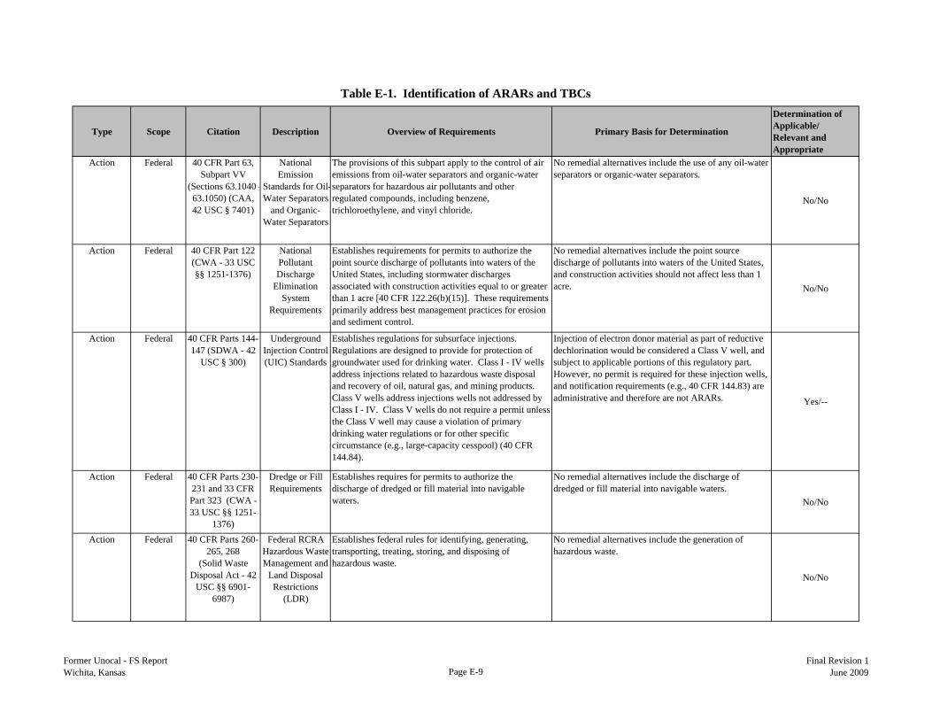
Table E-1. Identification of ARARs and TBCs
Type Scope Citation Description Overview of Requirements Primary Basis for Determination
Determination of Applicable/ Relevant and Appropriate
Action Federal 40 CFR Part 63, Subpart VV
(Sections 63.1040 -63.1050) (CAA, 42 USC § 7401)
National Emission
Standards for Oil-Water Separators
and Organic-Water Separators
The provisions of this subpart apply to the control of air emissions from oil-water separators and organic-water separators for hazardous air pollutants and other regulated compounds, including benzene, trichloroethylene, and vinyl chloride.
No remedial alternatives include the use of any oil-water separators or organic-water separators.
No/No
Action Federal 40 CFR Part 122 (CWA - 33 USC §§ 1251-1376)
National Pollutant Discharge
Elimination System
Requirements
Establishes requirements for permits to authorize the point source discharge of pollutants into waters of the United States, including stormwater discharges associated with construction activities equal to or greater than 1 acre [40 CFR 122.26(b)(15)]. These requirements primarily address best management practices for erosion and sediment control.
No remedial alternatives include the point source discharge of pollutants into waters of the United States, and construction activities should not affect less than 1 acre. No/No
Action Federal 40 CFR Parts 144-147 (SDWA - 42
USC § 300)
Underground Injection Control (UIC) Standards
Establishes regulations for subsurface injections. Regulations are designed to provide for protection of groundwater used for drinking water. Class I - IV wells address injections related to hazardous waste disposal and recovery of oil, natural gas, and mining products. Class V wells address injections wells not addressed by Class I - IV. Class V wells do not require a permit unless the Class V well may cause a violation of primary drinking water regulations or for other specific circumstance (e.g., large-capacity cesspool) (40 CFR 144.84).
Injection of electron donor material as part of reductive dechlorination would be considered a Class V well, and subject to applicable portions of this regulatory part. However, no permit is required for these injection wells, and notification requirements (e.g., 40 CFR 144.83) are administrative and therefore are not ARARs. Yes/--
Action Federal 40 CFR Parts 230-231 and 33 CFR Part 323 (CWA - 33 USC §§ 1251-
1376)
Dredge or Fill Requirements
Establishes requires for permits to authorize the discharge of dredged or fill material into navigable waters.
No remedial alternatives include the discharge of dredged or fill material into navigable waters.
No/No
Action Federal 40 CFR Parts 260-265, 268
(Solid Waste Disposal Act - 42
USC §§ 6901-6987)
Federal RCRA Hazardous Waste Management and
Land Disposal Restrictions
(LDR)
Establishes federal rules for identifying, generating, transporting, treating, storing, and disposing of hazardous waste.
No remedial alternatives include the generation of hazardous waste.
No/No
Former Unocal - FS ReportWichita, Kansas Page E-9
Final Revision 1June 2009

Table E-1. Identification of ARARs and TBCs
Type Scope Citation Description Overview of Requirements Primary Basis for Determination
Determination of Applicable/ Relevant and Appropriate
Action Federal 40 CFR Part 403 (CWA - 33 USC §§ 1251-1376)
National Pretreatment
Standards
Establishes standards for controlling pollutants which pass through or interfere with treatment processes in publicly owned treatment works (POTW) or which may contaminate sewage sludge.
No remedial alternatives include discharges to POTWs.
No/No
Action Federal 49 CFR Parts 171-173
Department of Transportation
Rules for Transportation of
Hazardous Materials
Establishes requirements for the transportation of hazardous materials, including container, placarding, etc.
Remedial alternatives have the potential for transportation of hazardous materials (e.g., electron donor material).
Yes/--
Action Federal 29 CFR Parts 1910 and 1926
Occupational Safety and
Health Administration
Establishes requirements for occupational safety and health, including hazardous material storage requirements and training requirements for personnel working on hazardous waste sites.
Remedial alternatives include working on a hazardous waste site and the potential for storage of hazardous materials. Yes/--
Action State KAR Title 28, Article 16
Water Pollution Control
Provides permitting framework and standards associated with discharges to surface waters.
No remedial actions propose a discharge to surface water. No/No
Action State KAR Title 28, Article 19
Kansas Air Regulations
Provides ambient air quality standards and air pollution control standards.
Remedial actions have the potential to create an air emission source. Yes/--
Action State KAR Title 28, Article 29
Kansas Solid Waste
Management Regulations
Establishes regulations for solid waste collection, storage, transportation, and disposal. Includes regulations for composting and landfill operations.
Remedial alternatives include monitoring well installation and groundwater monitoring, which generate minor amounts of solid waste (e.g., disposable PPE, soil cuttings). Solid wastes generated as part of alternatives are subject to these regulations.
Yes/--
Action State KAR Title 28, Article 30
Kansas Water Well
Construction and Abandonment
Specifies requirements for the construction and abandoment of water wells, including montioring wells.
Applicable for remedial action alternatives that propose to construct or abandon monitoring wells.
Yes/--
Action State KAR Title 28, Article 31
Kansas Hazardous Waste
Management Regulations
Establishes regulations for hazardous waste identification, storage, transportation, and disposal. Regulations include universal waste and used oil.
Remedial alternatives include monitoring well installation and groundwater monitoring, which generate minor amounts of solid waste (e.g., disposable PPE, soil cuttings). None of these waste are anticipated to be hazardous waste.
No/No
Action State KAR Title 28, Article 46
Kansas Underground
Injection Control Program
Establishes regulations for subsurface injections. State regulations general adopt federal regulations by reference.
Injection of electron donor material as part of reductive dechlorination would be considered a Class V well, and subject to applicable portions of this article. However, no permit is required for these injection wells, and notification requirements are administrative and therefore are not ARARs.
Yes/--
Former Unocal - FS ReportWichita, Kansas Page E-10
Final Revision 1June 2009
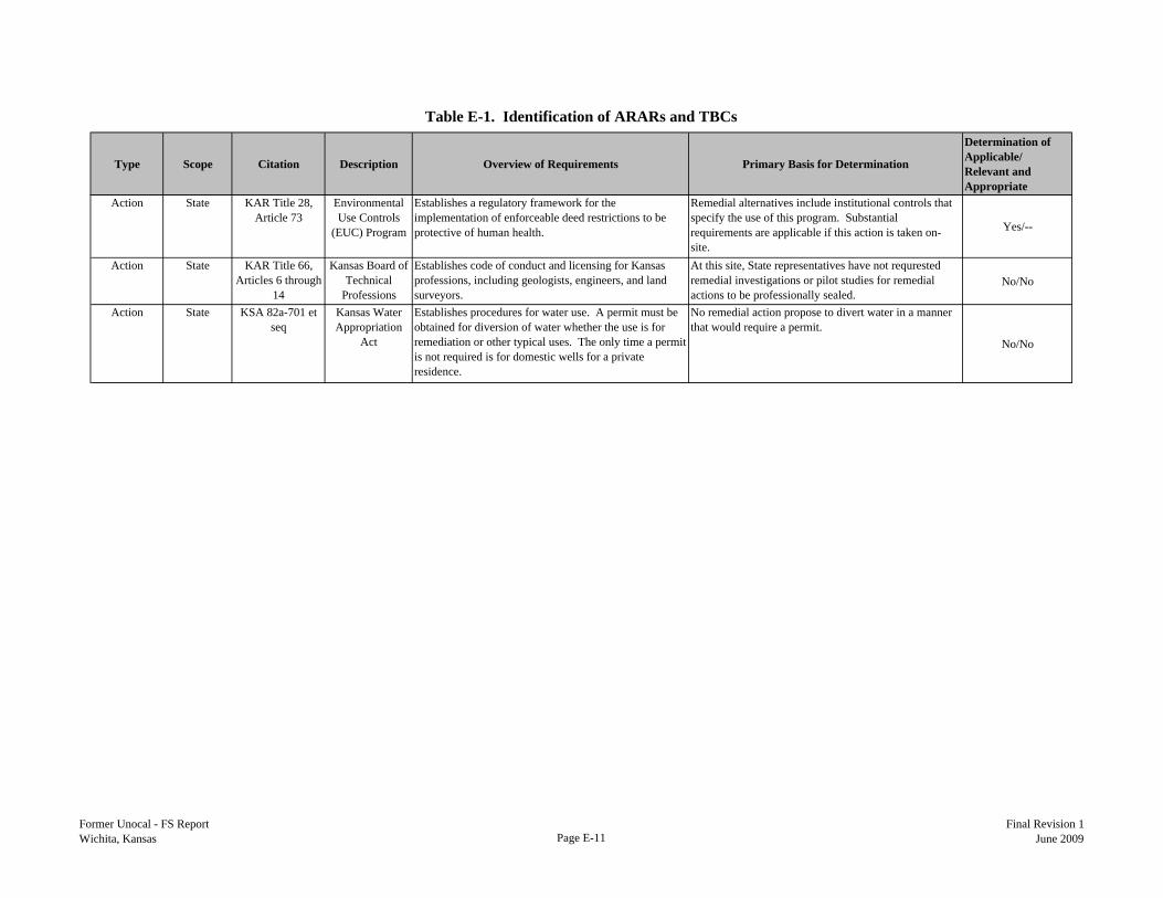
Table E-1. Identification of ARARs and TBCs
Type Scope Citation Description Overview of Requirements Primary Basis for Determination
Determination of Applicable/ Relevant and Appropriate
Action State KAR Title 28, Article 73
Environmental Use Controls
(EUC) Program
Establishes a regulatory framework for the implementation of enforceable deed restrictions to be protective of human health.
Remedial alternatives include institutional controls that specify the use of this program. Substantial requirements are applicable if this action is taken on-site.
Yes/--
Action State KAR Title 66, Articles 6 through
14
Kansas Board of Technical
Professions
Establishes code of conduct and licensing for Kansas professions, including geologists, engineers, and land surveyors.
At this site, State representatives have not requrested remedial investigations or pilot studies for remedial actions to be professionally sealed.
No/No
Action State KSA 82a-701 et seq
Kansas Water Appropriation
Act
Establishes procedures for water use. A permit must be obtained for diversion of water whether the use is for remediation or other typical uses. The only time a permit is not required is for domestic wells for a private residence.
No remedial action propose to divert water in a manner that would require a permit.
No/No
Former Unocal - FS ReportWichita, Kansas Page E-11
Final Revision 1June 2009

Appendix F
Calculations for Estimated Costs of Remedial Alternatives


Appendix F
Alternative 1 Cost Estimate
Former Unocal - FS Report Page F-1 Final Revision 1 Wichita, Kansas June 2009
No Action (Long-Term Monitoring) The SAP lists a core set of 28 wells for field parameters and VOCs (8260B). No MNA parameters will be analyzed. All wells in the network will be gauged for the water level. An annual groundwater report will issued yearly. Assumptions Current SAP and HASP will be used. Staff (mid-level geologist and project engineer) will come from Austin. Assume 16 hours prep, 10 hours for mob/demob Assume potentiometric takes 2 days - assuming all 69 wells are gauged Assume 6 wells can be sampled per day (take 5 days for sampling) - 10 hour days No Capital Cost (Use existing well network) Cost provided PER YEAR. A. DIRECT LABOR Regular Hours 2008 Contract Rate COSTS
Expert/Senior Principal 0 152.38 0 Project Manager 20 97.58 1,951.60 Includes field event Project Engineer/Scientist 132 77.61 10,244.52 + report writing Sr. Project Engineer/Scientist 8 97.58 780.64 Associate Scientist/Hydro/Geologist 132 70.88 9,356.16 Draftsman/CADD Operator 24 56.72 1,361.28 Specialist 60 62.20 3,732.00 (Incl. Base Labor, O/H, G&A & Profit)
Project Management (+10%) 2,742.62
TOTAL DIRECT LABOR 376 30,168.82
B. OTHER SIGNIFICANT COSTS 1. OFFICE COSTS/OTHER DIRECT COSTS UNITS RATE NO. COSTS
Printing and Copy - B&W (8.5 x 11) page 0.065 300 19.50 Printing and Copy - B&W (11 x 17) page 0.12 0 Printing and Copy - Color (8.5 x 11) page 0.75 80 60.00 Printing and Copy - Color (11 x 17) page 1.38 120 165.60 Color Covers and Spines each 2.70 8 21.60 Shipping (correspondence - up to 4 lbs) each 3.85 10 38.50 Shipping (reports - up to 10 lbs) each 8.31 4 33.24 Shipping (sample coolers - up to 75 lbs) each 58.43 0 Tabs each 0.49 60 29.40
TOTAL OFFICE COSTS/OTHER DIRECT COSTS 367.84
2. TRAVEL UNITS RATE NO. COSTS
RT from Austin to Kansas (Wichita) round trip 850.00 2 1,700.00 Days Per Diem day 132.00 18 2,376.00 Daily Truck Rental day 60.00 9 540.00 Parking day 8.00 9 72.00 Gasoline for rental vehicle gallon 4.00 120 480.00
TOTAL TRAVEL 5,168.00
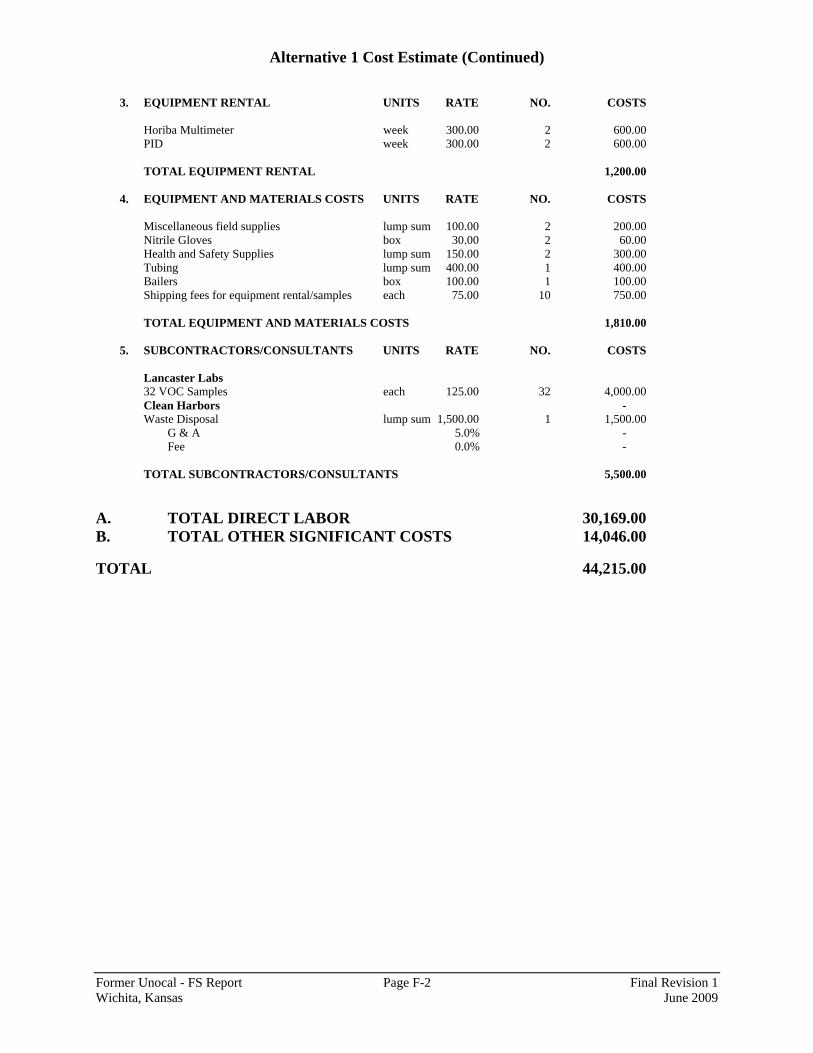
Alternative 1 Cost Estimate (Continued)
Former Unocal - FS Report Page F-2 Final Revision 1 Wichita, Kansas June 2009
3. EQUIPMENT RENTAL UNITS RATE NO. COSTS
Horiba Multimeter week 300.00 2 600.00 PID week 300.00 2 600.00 TOTAL EQUIPMENT RENTAL 1,200.00
4. EQUIPMENT AND MATERIALS COSTS UNITS RATE NO. COSTS
Miscellaneous field supplies lump sum 100.00 2 200.00 Nitrile Gloves box 30.00 2 60.00 Health and Safety Supplies lump sum 150.00 2 300.00 Tubing lump sum 400.00 1 400.00 Bailers box 100.00 1 100.00 Shipping fees for equipment rental/samples each 75.00 10 750.00
TOTAL EQUIPMENT AND MATERIALS COSTS 1,810.00
5. SUBCONTRACTORS/CONSULTANTS UNITS RATE NO. COSTS
Lancaster Labs 32 VOC Samples each 125.00 32 4,000.00 Clean Harbors - Waste Disposal lump sum 1,500.00 1 1,500.00
G & A 5.0% - Fee 0.0% -
TOTAL SUBCONTRACTORS/CONSULTANTS 5,500.00
A. TOTAL DIRECT LABOR 30,169.00 B. TOTAL OTHER SIGNIFICANT COSTS 14,046.00 TOTAL 44,215.00

Alternative 2 Cost Estimate
Former Unocal - FS Report Page F-3 Final Revision 1 Wichita, Kansas June 2009
MNA, EUC Program, and LTM The SAP lists a core set of 28 wells for field parameters and VOCs (8260B). Plus 6 existing wells for MNA and 4 new wells. (TOTAL wells = 38) Assume 25 wells will be analyzed for MNA parameters too (alkalinity, chloride, sulfate, ethane, ethene, and methane). A one time event for the 25 wells will occur in which samples will be collected and analyzed for phosphorus, potassium, total organic carbon, and dehalococluides sp. Bacteria Capital Costs I. EUC Program
A. DIRECT LABOR Regular Hours 2008 Contract Rate COSTS
Expert/Senior Principal 0 152.38 0 Project Manager 20 97.58 1,951.60 Project Engineer/Scientist 40 77.61 3,104.40 Sr. Project Engineer/Scientist 8 97.58 780.64 Associate Scientist/Hydro/Geologist 40 70.88 2,835.20 Draftsman/CADD Operator 16 56.72 907.52 Specialist 8 62.20 497.60 (Incl. Base Labor, O/H, G&A & Profit) Project Management (+10%) 1,007.70 TOTAL DIRECT LABOR 132 11,084.66
B. OTHER SIGNIFICANT COSTS
1. OFFICE COSTS/OTHER DIRECT COSTS UNITS RATE NO. COSTS Printing and Copy - B&W (8.5 x 11) page 0.065 300 19.50 Printing and Copy - B&W (11 x 17) page 0.12 0 Printing and Copy - Color (8.5 x 11) page 0.75 40 30.00 Printing and Copy - Color (11 x 17) page 1.38 80 110.40 Color Covers and Spines each 2.70 8 21.60 Shipping (correspondence - up to 4 lbs) each 3.85 10 38.50 Shipping (reports - up to 10 lbs) each 8.31 0 Shipping (sample coolers - up to 75 lbs) each 58.43 0 Tabs each 0.49 40 19.60 TOTAL OFFICE COSTS/OTHER DIRECT COSTS 239.60
2. SUBCONTRACTORS/CONSULTANTS UNITS RATE NO. COSTS
Surveyor Legal Survey Lump Sum 5,000.00 1 5,000.00
G & A 5.0% 250.00 Fee 0.0%
- TOTAL SUBCONTRACTORS/CONSULTANTS 5,250.00
KDHE Fee (MAXIMUM) 10,000.00
TOTAL 26,574.26
II. Well Installation Based on Well installation Cost estimate from 2008 (minus HASP update) Assume installing 4 wells and 5 days of work
TOTAL 31,500.00

Alternative 2 Cost Estimate (Continued)
Former Unocal - FS Report Page F-4 Final Revision 1 Wichita, Kansas June 2009
III. SUBCONTRACTORS/CONSULTANTS UNITS RATE NO. COSTS
Lancaster Labs Addl MNA each 227.00 25 5,675.00 TOTAL SUBCONTRACTORS/CONSULTANTS 5,675.00
Capital Costs Total 63,749.26
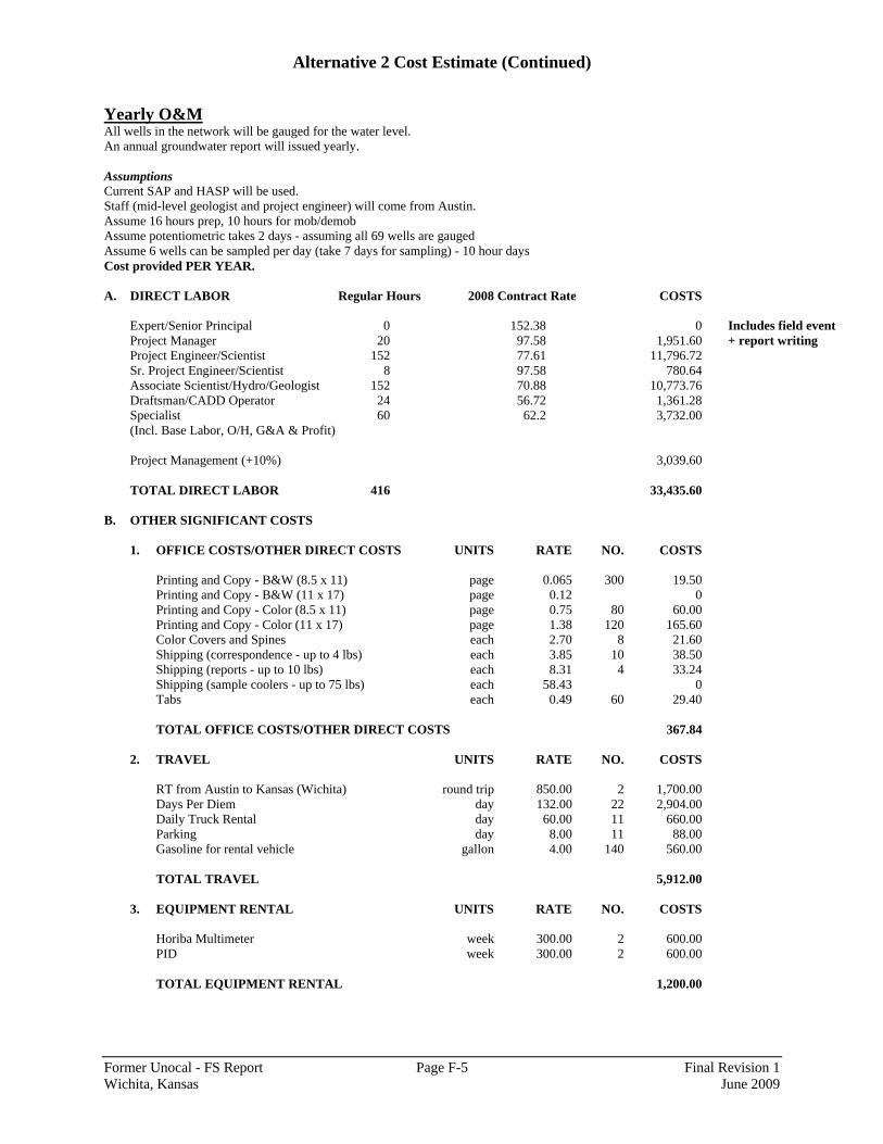
Alternative 2 Cost Estimate (Continued)
Former Unocal - FS Report Page F-5 Final Revision 1 Wichita, Kansas June 2009
Yearly O&M All wells in the network will be gauged for the water level. An annual groundwater report will issued yearly. Assumptions Current SAP and HASP will be used. Staff (mid-level geologist and project engineer) will come from Austin. Assume 16 hours prep, 10 hours for mob/demob Assume potentiometric takes 2 days - assuming all 69 wells are gauged Assume 6 wells can be sampled per day (take 7 days for sampling) - 10 hour days Cost provided PER YEAR. A. DIRECT LABOR Regular Hours 2008 Contract Rate COSTS
Expert/Senior Principal 0 152.38 0 Includes field event Project Manager 20 97.58 1,951.60 + report writing Project Engineer/Scientist 152 77.61 11,796.72 Sr. Project Engineer/Scientist 8 97.58 780.64 Associate Scientist/Hydro/Geologist 152 70.88 10,773.76 Draftsman/CADD Operator 24 56.72 1,361.28 Specialist 60 62.2 3,732.00 (Incl. Base Labor, O/H, G&A & Profit)
Project Management (+10%) 3,039.60 TOTAL DIRECT LABOR 416 33,435.60
B. OTHER SIGNIFICANT COSTS
1. OFFICE COSTS/OTHER DIRECT COSTS UNITS RATE NO. COSTS
Printing and Copy - B&W (8.5 x 11) page 0.065 300 19.50 Printing and Copy - B&W (11 x 17) page 0.12 0 Printing and Copy - Color (8.5 x 11) page 0.75 80 60.00 Printing and Copy - Color (11 x 17) page 1.38 120 165.60 Color Covers and Spines each 2.70 8 21.60 Shipping (correspondence - up to 4 lbs) each 3.85 10 38.50 Shipping (reports - up to 10 lbs) each 8.31 4 33.24 Shipping (sample coolers - up to 75 lbs) each 58.43 0 Tabs each 0.49 60 29.40
TOTAL OFFICE COSTS/OTHER DIRECT COSTS 367.84
2. TRAVEL UNITS RATE NO. COSTS
RT from Austin to Kansas (Wichita) round trip 850.00 2 1,700.00 Days Per Diem day 132.00 22 2,904.00 Daily Truck Rental day 60.00 11 660.00 Parking day 8.00 11 88.00 Gasoline for rental vehicle gallon 4.00 140 560.00
TOTAL TRAVEL 5,912.00
3. EQUIPMENT RENTAL UNITS RATE NO. COSTS
Horiba Multimeter week 300.00 2 600.00 PID week 300.00 2 600.00
TOTAL EQUIPMENT RENTAL 1,200.00
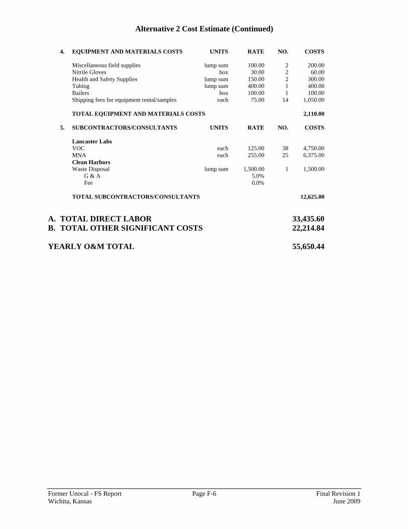
Alternative 2 Cost Estimate (Continued)
Former Unocal - FS Report Page F-6 Final Revision 1 Wichita, Kansas June 2009
4. EQUIPMENT AND MATERIALS COSTS UNITS RATE NO. COSTS
Miscellaneous field supplies lump sum 100.00 2 200.00 Nitrile Gloves box 30.00 2 60.00 Health and Safety Supplies lump sum 150.00 2 300.00 Tubing lump sum 400.00 1 400.00 Bailers box 100.00 1 100.00 Shipping fees for equipment rental/samples each 75.00 14 1,050.00
TOTAL EQUIPMENT AND MATERIALS COSTS 2,110.00
5. SUBCONTRACTORS/CONSULTANTS UNITS RATE NO. COSTS
Lancaster Labs VOC each 125.00 38 4,750.00 MNA each 255.00 25 6,375.00 Clean Harbors Waste Disposal lump sum 1,500.00 1 1,500.00
G & A 5.0% Fee 0.0%
TOTAL SUBCONTRACTORS/CONSULTANTS 12,625.00
A. TOTAL DIRECT LABOR 33,435.60 B. TOTAL OTHER SIGNIFICANT COSTS 22,214.84 YEARLY O&M TOTAL 55,650.44
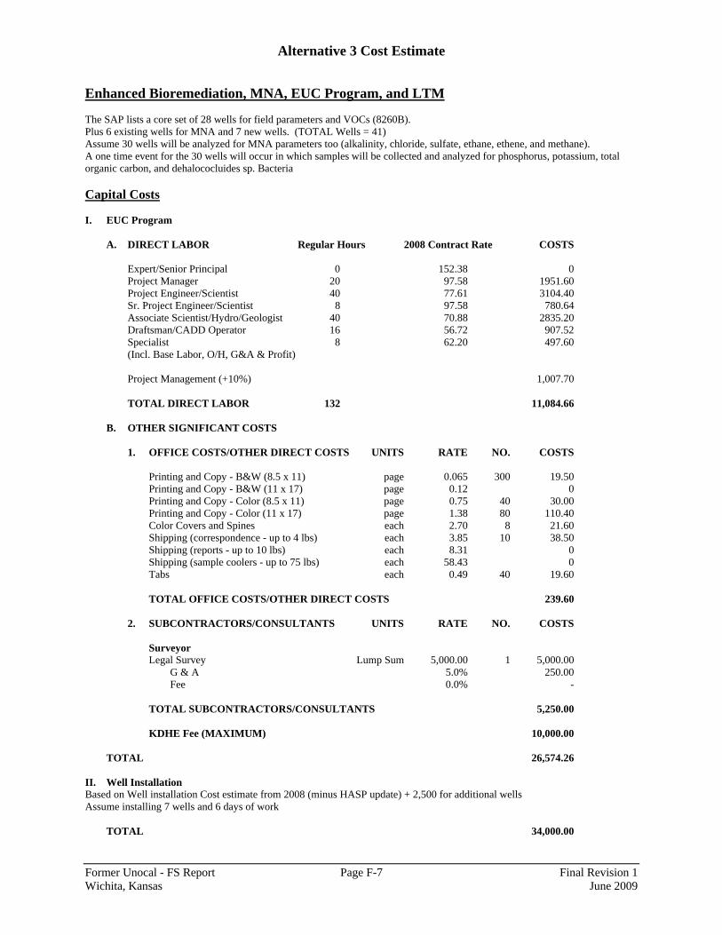
Alternative 3 Cost Estimate
Former Unocal - FS Report Page F-7 Final Revision 1 Wichita, Kansas June 2009
Enhanced Bioremediation, MNA, EUC Program, and LTM The SAP lists a core set of 28 wells for field parameters and VOCs (8260B). Plus 6 existing wells for MNA and 7 new wells. (TOTAL Wells = 41) Assume 30 wells will be analyzed for MNA parameters too (alkalinity, chloride, sulfate, ethane, ethene, and methane). A one time event for the 30 wells will occur in which samples will be collected and analyzed for phosphorus, potassium, total organic carbon, and dehalococluides sp. Bacteria Capital Costs I. EUC Program
A. DIRECT LABOR Regular Hours 2008 Contract Rate COSTS
Expert/Senior Principal 0 152.38 0 Project Manager 20 97.58 1951.60 Project Engineer/Scientist 40 77.61 3104.40 Sr. Project Engineer/Scientist 8 97.58 780.64 Associate Scientist/Hydro/Geologist 40 70.88 2835.20 Draftsman/CADD Operator 16 56.72 907.52 Specialist 8 62.20 497.60 (Incl. Base Labor, O/H, G&A & Profit) Project Management (+10%) 1,007.70 TOTAL DIRECT LABOR 132 11,084.66
B. OTHER SIGNIFICANT COSTS
1. OFFICE COSTS/OTHER DIRECT COSTS UNITS RATE NO. COSTS
Printing and Copy - B&W (8.5 x 11) page 0.065 300 19.50 Printing and Copy - B&W (11 x 17) page 0.12 0 Printing and Copy - Color (8.5 x 11) page 0.75 40 30.00 Printing and Copy - Color (11 x 17) page 1.38 80 110.40 Color Covers and Spines each 2.70 8 21.60 Shipping (correspondence - up to 4 lbs) each 3.85 10 38.50 Shipping (reports - up to 10 lbs) each 8.31 0 Shipping (sample coolers - up to 75 lbs) each 58.43 0 Tabs each 0.49 40 19.60
TOTAL OFFICE COSTS/OTHER DIRECT COSTS 239.60
2. SUBCONTRACTORS/CONSULTANTS UNITS RATE NO. COSTS
Surveyor Legal Survey Lump Sum 5,000.00 1 5,000.00
G & A 5.0% 250.00 Fee 0.0% -
TOTAL SUBCONTRACTORS/CONSULTANTS 5,250.00
KDHE Fee (MAXIMUM) 10,000.00
TOTAL 26,574.26
II. Well Installation Based on Well installation Cost estimate from 2008 (minus HASP update) + 2,500 for additional wells Assume installing 7 wells and 6 days of work
TOTAL 34,000.00
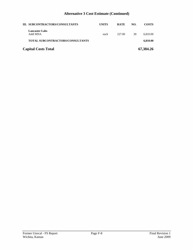
Alternative 3 Cost Estimate (Continued)
Former Unocal - FS Report Page F-8 Final Revision 1 Wichita, Kansas June 2009
III. SUBCONTRACTORS/CONSULTANTS UNITS RATE NO. COSTS
Lancaster Labs Addl MNA each 227.00 30 6,810.00
TOTAL SUBCONTRACTORS/CONSULTANTS 6,810.00
Capital Costs Total 67,384.26

Alternative 3 Cost Estimate (Continued)
Former Unocal - FS Report Page F-9 Final Revision 1 Wichita, Kansas June 2009
HRC® Injection Assumptions Staff (mid-level geologist and project engineer) will come from Austin. Assume 50 hours prep per person (2 people, includes workplan) for initial event, 30 hrs prep per person Year 5 and 10 Assumes 3 events: Initial injection = 14 days; Year 5 injection = 12 days; Year 10 injection = 7 days. 10 hours per day 10 hours for mob/demob per event (3 events) Initial Injection A. DIRECT LABOR Regular Hours 2008 Contract Rate COSTS
Expert/Senior Principal 0 152.38 0 Includes field event Project Manager 20 97.58 1951.60 + workplan Project Engineer/Scientist 200 77.61 15,522.00 Sr. Project Engineer/Scientist 16 97.58 1,561.28 Associate Scientist/Hydro/Geologist 200 70.88 14,176.00 Draftsman/CADD Operator 16 56.72 907.52 Specialist 20 62.20 1,244.00 (Incl. Base Labor, O/H, G&A & Profit) Project Management (+10%) 3,536.24 TOTAL DIRECT LABOR 472 38,898.64
B. OTHER SIGNIFICANT COSTS
1. OFFICE COSTS/OTHER DIRECT COSTS UNITS RATE NO. COSTS
Printing and Copy - B&W (8.5 x 11) page 0.065 300 19.50 Printing and Copy - B&W (11 x 17) page 0.12 0 Printing and Copy - Color (8.5 x 11) page 0.75 80 60.00 Printing and Copy - Color (11 x 17) page 1.38 120 165.60 Color Covers and Spines each 2.70 8 21.60 Shipping (correspondence - up to 4 lbs) each 3.85 10 38.50 Shipping (reports - up to 10 lbs) each 8.31 4 33.24 Shipping (sample coolers - up to 75 lbs) each 58.43 0 Tabs each 0.49 60 29.40 TOTAL OFFICE COSTS/OTHER DIRECT COSTS 367.84
2. TRAVEL UNITS RATE NO. COSTS
RT from Austin to Kansas (Wichita) round trip 850.00 2 1,700.00 Days Per Diem day 132.00 28 3,696.00 Daily Truck Rental day 60.00 14 840.00 Parking day 8.00 28 224.00 Gasoline for rental vehicle gallon 4.00 100 400.00
TOTAL TRAVEL 6,860.00
3. EQUIPMENT RENTAL UNITS RATE NO. COSTS
PID week 300.00 2 600.00
TOTAL EQUIPMENT RENTAL 600.00

Alternative 3 Cost Estimate (Continued)
Former Unocal - FS Report Page F-10 Final Revision 1 Wichita, Kansas June 2009
4. EQUIPMENT AND MATERIALS COSTS UNITS RATE NO. COSTS
Miscellaneous field supplies lump sum 100.00 2 200.00 Nitrile Gloves box 30.00 4 120.00 Health and Safety Supplies lump sum 150.00 2 300.00
TOTAL EQUIPMENT AND MATERIALS COSTS 620.00
5. SUBCONTRACTORS/CONSULTANTS UNITS RATE NO. COSTS
Driller - PSA Environmental Initial HRC® Injection lump sum 36,096.50 1 36,096.50 Regenesis HRC® Purchase lump sum 94,887.00 1 94,887.00 Clean Harbors Waste Disposal lump sum 1,500.00 1 1,500.00
G & A 5.0% 6,624.18 Fee 0.0% -
TOTAL SUBCONTRACTORS/CONSULTANTS 139,107.68
A. TOTAL DIRECT LABOR 38,898.64 B. TOTAL OTHER SIGNIFICANT COSTS 147,555.52 TOTAL 186,454.16
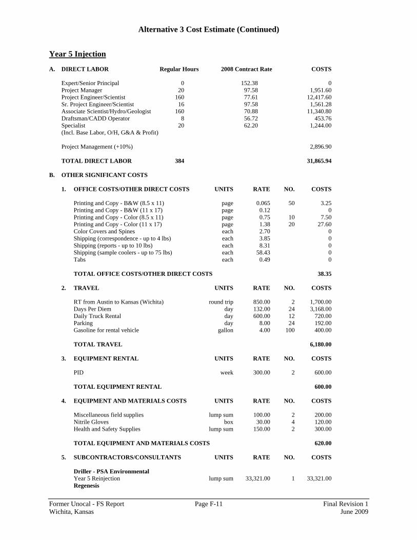
Alternative 3 Cost Estimate (Continued)
Former Unocal - FS Report Page F-11 Final Revision 1 Wichita, Kansas June 2009
Year 5 Injection A. DIRECT LABOR Regular Hours 2008 Contract Rate COSTS
Expert/Senior Principal 0 152.38 0 Project Manager 20 97.58 1,951.60 Project Engineer/Scientist 160 77.61 12,417.60 Sr. Project Engineer/Scientist 16 97.58 1,561.28 Associate Scientist/Hydro/Geologist 160 70.88 11,340.80 Draftsman/CADD Operator 8 56.72 453.76 Specialist 20 62.20 1,244.00 (Incl. Base Labor, O/H, G&A & Profit) Project Management (+10%) 2,896.90 TOTAL DIRECT LABOR 384 31,865.94
B. OTHER SIGNIFICANT COSTS
1. OFFICE COSTS/OTHER DIRECT COSTS UNITS RATE NO. COSTS
Printing and Copy - B&W (8.5 x 11) page 0.065 50 3.25 Printing and Copy - B&W (11 x 17) page 0.12 0 Printing and Copy - Color (8.5 x 11) page 0.75 10 7.50 Printing and Copy - Color (11 x 17) page 1.38 20 27.60 Color Covers and Spines each 2.70 0 Shipping (correspondence - up to 4 lbs) each 3.85 0 Shipping (reports - up to 10 lbs) each 8.31 0 Shipping (sample coolers - up to 75 lbs) each 58.43 0 Tabs each 0.49 0
TOTAL OFFICE COSTS/OTHER DIRECT COSTS 38.35
2. TRAVEL UNITS RATE NO. COSTS
RT from Austin to Kansas (Wichita) round trip 850.00 2 1,700.00 Days Per Diem day 132.00 24 3,168.00 Daily Truck Rental day 600.00 12 720.00 Parking day 8.00 24 192.00 Gasoline for rental vehicle gallon 4.00 100 400.00
TOTAL TRAVEL 6,180.00
3. EQUIPMENT RENTAL UNITS RATE NO. COSTS
PID week 300.00 2 600.00
TOTAL EQUIPMENT RENTAL 600.00
4. EQUIPMENT AND MATERIALS COSTS UNITS RATE NO. COSTS
Miscellaneous field supplies lump sum 100.00 2 200.00 Nitrile Gloves box 30.00 4 120.00 Health and Safety Supplies lump sum 150.00 2 300.00
TOTAL EQUIPMENT AND MATERIALS COSTS 620.00
5. SUBCONTRACTORS/CONSULTANTS UNITS RATE NO. COSTS
Driller - PSA Environmental Year 5 Reinjection lump sum 33,321.00 1 33,321.00 Regenesis
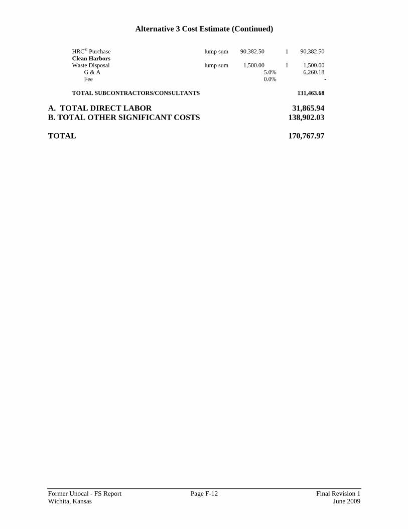
Alternative 3 Cost Estimate (Continued)
Former Unocal - FS Report Page F-12 Final Revision 1 Wichita, Kansas June 2009
HRC® Purchase lump sum 90,382.50 1 90,382.50 Clean Harbors Waste Disposal lump sum 1,500.00 1 1,500.00
G & A 5.0% 6,260.18 Fee 0.0% -
TOTAL SUBCONTRACTORS/CONSULTANTS 131,463.68
A. TOTAL DIRECT LABOR 31,865.94 B. TOTAL OTHER SIGNIFICANT COSTS 138,902.03 TOTAL 170,767.97

Alternative 3 Cost Estimate (Continued)
Former Unocal - FS Report Page F-13 Final Revision 1 Wichita, Kansas June 2009
Year 10 Injection A. DIRECT LABOR Regular Hours 2008 Contract Rate COSTS
Expert/Senior Principal 0 152.38 0 Project Manager 20 97.58 1,951.60 Project Engineer/Scientist 110 77.61 8,537.10 Sr. Project Engineer/Scientist 16 97.58 1,561.28 Associate Scientist/Hydro/Geologist 110 70.88 7,796.80 Draftsman/CADD Operator 8 56.72 453.76 Specialist 20 62.20 1,244.00 (Incl. Base Labor, O/H, G&A & Profit) Project Management (+10%) 2,154.45 TOTAL DIRECT LABOR 284 23,698.99
B. OTHER SIGNIFICANT COSTS
1. OFFICE COSTS/OTHER DIRECT COSTS UNITS RATE NO. COSTS
Printing and Copy - B&W (8.5 x 11) page 0.065 50 3.25 Printing and Copy - B&W (11 x 17) page 0.12 0 Printing and Copy - Color (8.5 x 11) page 0.75 10 7.50 Printing and Copy - Color (11 x 17) page 1.38 20 27.60 Color Covers and Spines each 2.70 0 Shipping (correspondence - up to 4 lbs) each 3.85 0 Shipping (reports - up to 10 lbs) each 8.31 0 Shipping (sample coolers - up to 75 lbs) each 58.43 0 Tabs each 0.49 0
TOTAL OFFICE COSTS/OTHER DIRECT COSTS 38.35
2. TRAVEL UNITS RATE NO. COSTS
RT from Austin to Kansas (Wichita) round trip 850.00 2 1,700.00 Days Per Diem day 132.00 14 1,848.00 Daily Truck Rental day 60.00 7 420.00 Parking day 8.00 14 112.00 Gasoline for rental vehicle gallon 4.00 60 240.00
TOTAL TRAVEL 4,320.00
3. EQUIPMENT RENTAL UNITS RATE NO. COSTS
PID week 300.00 1 300.00
TOTAL EQUIPMENT RENTAL 300.00
4. EQUIPMENT AND MATERIALS COSTS UNITS RATE NO. COSTS
Miscellaneous field supplies lump sum 100.00 1 100.00 Nitrile Gloves box 30.00 2 60.00 Health and Safety Supplies lump sum 150.00 1 150.00
TOTAL EQUIPMENT AND MATERIALS COSTS 310.00

Alternative 3 Cost Estimate (Continued)
Former Unocal - FS Report Page F-14 Final Revision 1 Wichita, Kansas June 2009
5. SUBCONTRACTORS/CONSULTANTS UNITS RATE NO. COSTS
Driller - PSA Environmental Year 10 Reinjection lump sum 22,647.50 1 22,647.50 Regenesis HRC® Purchase lump sum 67,041.00 1 67,041.00 Clean Harbors Waste Disposal lump sum 1,500.00 1 1,500.00
G & A 5.0% 4,559.43 Fee 0.0% -
TOTAL SUBCONTRACTORS/CONSULTANTS 95,747.93
A. TOTAL DIRECT LABOR 23,698.99 B. TOTAL OTHER SIGNIFICANT COSTS 100,716.28 TOTAL 124,415.27

Alternative 3 Cost Estimate (Continued)
Former Unocal - FS Report Page F-15 Final Revision 1 Wichita, Kansas June 2009
Yearly O&M All wells in the network will be gauged for the water level. An annual groundwater report will issued yearly. Assumptions Current SAP and HASP will be used. Staff (mid-level geologist and project engineer) will come from Austin. Assume 16 hours prep, 10 hours for mob/demob Assume potentiometric takes 2 days - assuming all 69 wells are gauged Assume 6 wells can be sampled per day (take 7 days for sampling) - 10 hour days Cost provided PER YEAR. A. DIRECT LABOR Regular Hours 2008 Contract Rate COSTS
Expert/Senior Principal 0 152.38 0 Includes field event Project Manager 20 97.58 1,951.60 + report writing Project Engineer/Scientist 152 77.61 11,796.72 Sr. Project Engineer/Scientist 8 97.58 780.64 Associate Scientist/Hydro/Geologist 152 70.88 10,773.76 Draftsman/CADD Operator 24 56.72 1,361.28 Specialist 60 62.20 3,732.00 (Incl. Base Labor, O/H, G&A & Profit) Project Management (+10%) 3,039.60 TOTAL DIRECT LABOR 416 33,435.60
B. OTHER SIGNIFICANT COSTS
1. OFFICE COSTS/OTHER DIRECT COSTS UNITS RATE NO. COSTS
Printing and Copy - B&W (8.5 x 11) page 0.065 300 19.50 Printing and Copy - B&W (11 x 17) page 0.12 0 Printing and Copy - Color (8.5 x 11) page 0.75 80 60.00 Printing and Copy - Color (11 x 17) page 1.38 120 165.60 Color Covers and Spines each 2.70 8 21.60 Shipping (correspondence - up to 4 lbs) each 3.85 10 38.50 Shipping (reports - up to 10 lbs) each 8.31 4 33.24 Shipping (sample coolers - up to 75 lbs) each 58.43 0 Tabs each 0.49 60 29.40
TOTAL OFFICE COSTS/OTHER DIRECT COSTS 367.84
2. TRAVEL UNITS RATE NO. COSTS
RT from Austin to Kansas (Wichita) round trip 850.00 2 1,700.00 Days Per Diem day 132.00 22 2,904.00 Daily Truck Rental day 60.00 11 660.00 Parking day 8.00 22 176.00 Gasoline for rental vehicle gallon 4.00 140 560.00
TOTAL TRAVEL 6,000.00
3. EQUIPMENT RENTAL UNITS RATE NO. COSTS
Horiba Multimeter week 300.00 2 600.00 PID week 300.00 2 600.00
TOTAL EQUIPMENT RENTAL 1,200.00
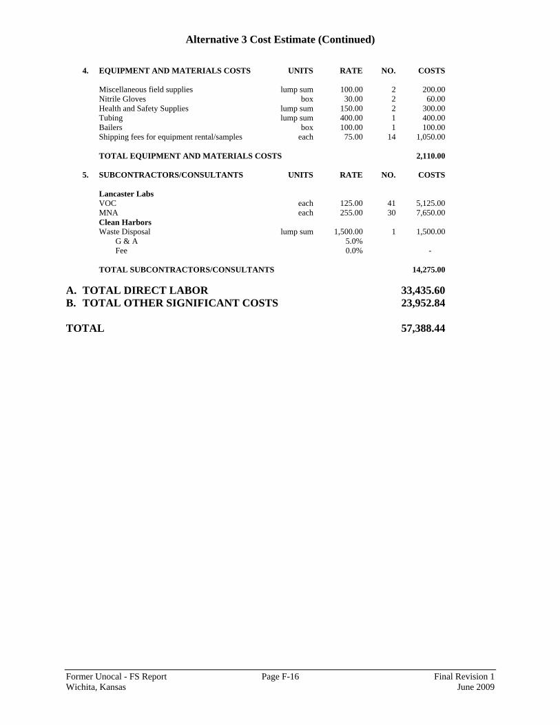
Alternative 3 Cost Estimate (Continued)
Former Unocal - FS Report Page F-16 Final Revision 1 Wichita, Kansas June 2009
4. EQUIPMENT AND MATERIALS COSTS UNITS RATE NO. COSTS
Miscellaneous field supplies lump sum 100.00 2 200.00 Nitrile Gloves box 30.00 2 60.00 Health and Safety Supplies lump sum 150.00 2 300.00 Tubing lump sum 400.00 1 400.00 Bailers box 100.00 1 100.00 Shipping fees for equipment rental/samples each 75.00 14 1,050.00
TOTAL EQUIPMENT AND MATERIALS COSTS 2,110.00
5. SUBCONTRACTORS/CONSULTANTS UNITS RATE NO. COSTS
Lancaster Labs VOC each 125.00 41 5,125.00 MNA each 255.00 30 7,650.00 Clean Harbors Waste Disposal lump sum 1,500.00 1 1,500.00
G & A 5.0% Fee 0.0% -
TOTAL SUBCONTRACTORS/CONSULTANTS 14,275.00
A. TOTAL DIRECT LABOR 33,435.60 B. TOTAL OTHER SIGNIFICANT COSTS 23,952.84 TOTAL 57,388.44
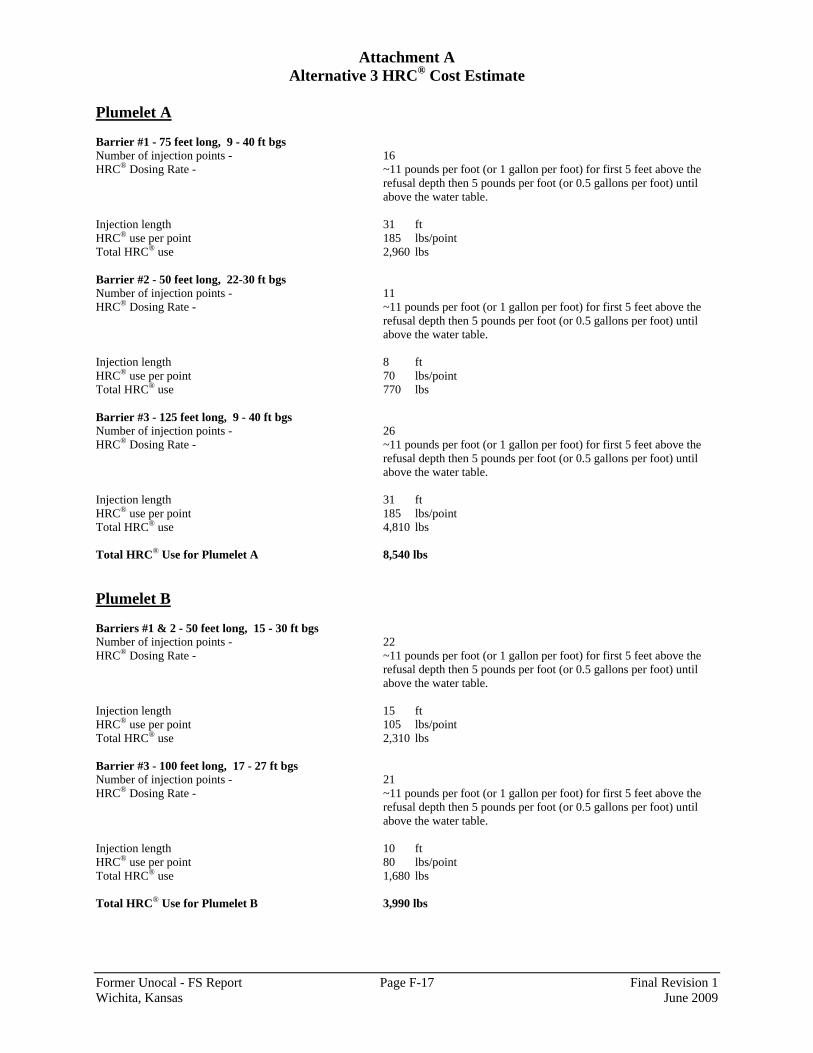
Attachment A Alternative 3 HRC® Cost Estimate
Former Unocal - FS Report Page F-17 Final Revision 1 Wichita, Kansas June 2009
Plumelet A Barrier #1 - 75 feet long, 9 - 40 ft bgs Number of injection points - 16 HRC® Dosing Rate - ~11 pounds per foot (or 1 gallon per foot) for first 5 feet above the
refusal depth then 5 pounds per foot (or 0.5 gallons per foot) until above the water table.
Injection length 31 ft HRC® use per point 185 lbs/point Total HRC® use 2,960 lbs Barrier #2 - 50 feet long, 22-30 ft bgs Number of injection points - 11 HRC® Dosing Rate - ~11 pounds per foot (or 1 gallon per foot) for first 5 feet above the
refusal depth then 5 pounds per foot (or 0.5 gallons per foot) until above the water table.
Injection length 8 ft HRC® use per point 70 lbs/point Total HRC® use 770 lbs Barrier #3 - 125 feet long, 9 - 40 ft bgs Number of injection points - 26 HRC® Dosing Rate - ~11 pounds per foot (or 1 gallon per foot) for first 5 feet above the
refusal depth then 5 pounds per foot (or 0.5 gallons per foot) until above the water table.
Injection length 31 ft HRC® use per point 185 lbs/point Total HRC® use 4,810 lbs Total HRC® Use for Plumelet A 8,540 lbs Plumelet B Barriers #1 & 2 - 50 feet long, 15 - 30 ft bgs Number of injection points - 22 HRC® Dosing Rate - ~11 pounds per foot (or 1 gallon per foot) for first 5 feet above the
refusal depth then 5 pounds per foot (or 0.5 gallons per foot) until above the water table.
Injection length 15 ft HRC® use per point 105 lbs/point Total HRC® use 2,310 lbs Barrier #3 - 100 feet long, 17 - 27 ft bgs Number of injection points - 21 HRC® Dosing Rate - ~11 pounds per foot (or 1 gallon per foot) for first 5 feet above the
refusal depth then 5 pounds per foot (or 0.5 gallons per foot) until above the water table.
Injection length 10 ft HRC® use per point 80 lbs/point Total HRC® use 1,680 lbs Total HRC® Use for Plumelet B 3,990 lbs
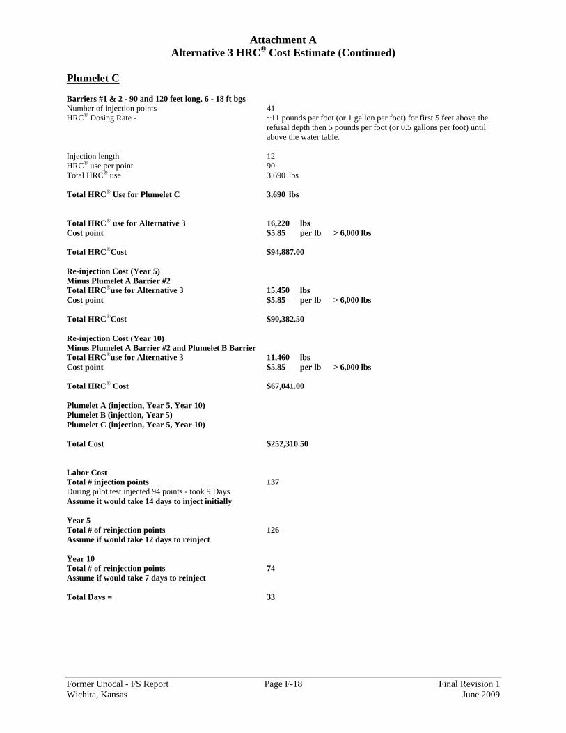
Attachment A Alternative 3 HRC® Cost Estimate (Continued)
Former Unocal - FS Report Page F-18 Final Revision 1 Wichita, Kansas June 2009
Plumelet C Barriers #1 & 2 - 90 and 120 feet long, 6 - 18 ft bgs Number of injection points - 41 HRC® Dosing Rate - ~11 pounds per foot (or 1 gallon per foot) for first 5 feet above the
refusal depth then 5 pounds per foot (or 0.5 gallons per foot) until above the water table.
Injection length 12 HRC® use per point 90 Total HRC® use 3,690 lbs Total HRC® Use for Plumelet C 3,690 lbs Total HRC® use for Alternative 3 16,220 lbs Cost point $5.85 per lb > 6,000 lbs Total HRC®Cost $94,887.00 Re-injection Cost (Year 5) Minus Plumelet A Barrier #2 Total HRC®use for Alternative 3 15,450 lbs Cost point $5.85 per lb > 6,000 lbs Total HRC®Cost $90,382.50 Re-injection Cost (Year 10) Minus Plumelet A Barrier #2 and Plumelet B Barrier Total HRC®use for Alternative 3 11,460 lbs Cost point $5.85 per lb > 6,000 lbs Total HRC® Cost $67,041.00 Plumelet A (injection, Year 5, Year 10) Plumelet B (injection, Year 5) Plumelet C (injection, Year 5, Year 10) Total Cost $252,310.50 Labor Cost Total # injection points 137 During pilot test injected 94 points - took 9 Days Assume it would take 14 days to inject initially Year 5 Total # of reinjection points 126 Assume if would take 12 days to reinject Year 10 Total # of reinjection points 74 Assume if would take 7 days to reinject Total Days = 33
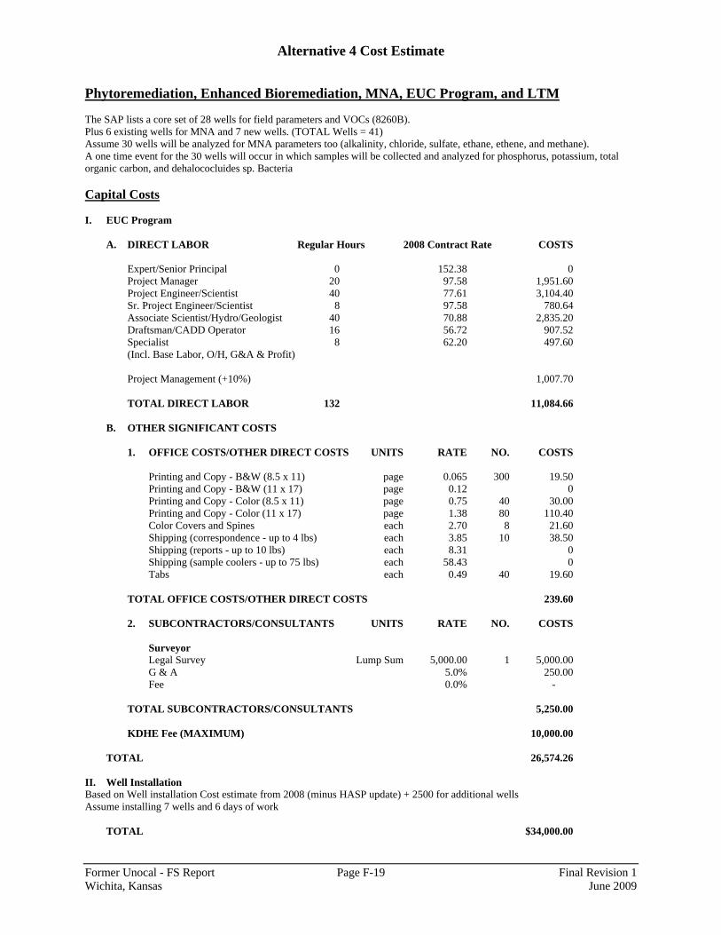
Alternative 4 Cost Estimate
Former Unocal - FS Report Page F-19 Final Revision 1 Wichita, Kansas June 2009
Phytoremediation, Enhanced Bioremediation, MNA, EUC Program, and LTM The SAP lists a core set of 28 wells for field parameters and VOCs (8260B). Plus 6 existing wells for MNA and 7 new wells. (TOTAL Wells = 41) Assume 30 wells will be analyzed for MNA parameters too (alkalinity, chloride, sulfate, ethane, ethene, and methane). A one time event for the 30 wells will occur in which samples will be collected and analyzed for phosphorus, potassium, total organic carbon, and dehalococluides sp. Bacteria Capital Costs I. EUC Program
A. DIRECT LABOR Regular Hours 2008 Contract Rate COSTS
Expert/Senior Principal 0 152.38 0 Project Manager 20 97.58 1,951.60 Project Engineer/Scientist 40 77.61 3,104.40 Sr. Project Engineer/Scientist 8 97.58 780.64 Associate Scientist/Hydro/Geologist 40 70.88 2,835.20 Draftsman/CADD Operator 16 56.72 907.52 Specialist 8 62.20 497.60 (Incl. Base Labor, O/H, G&A & Profit) Project Management (+10%) 1,007.70 TOTAL DIRECT LABOR 132 11,084.66
B. OTHER SIGNIFICANT COSTS
1. OFFICE COSTS/OTHER DIRECT COSTS UNITS RATE NO. COSTS
Printing and Copy - B&W (8.5 x 11) page 0.065 300 19.50 Printing and Copy - B&W (11 x 17) page 0.12 0 Printing and Copy - Color (8.5 x 11) page 0.75 40 30.00 Printing and Copy - Color (11 x 17) page 1.38 80 110.40 Color Covers and Spines each 2.70 8 21.60 Shipping (correspondence - up to 4 lbs) each 3.85 10 38.50 Shipping (reports - up to 10 lbs) each 8.31 0 Shipping (sample coolers - up to 75 lbs) each 58.43 0 Tabs each 0.49 40 19.60
TOTAL OFFICE COSTS/OTHER DIRECT COSTS 239.60
2. SUBCONTRACTORS/CONSULTANTS UNITS RATE NO. COSTS
Surveyor Legal Survey Lump Sum 5,000.00 1 5,000.00 G & A 5.0% 250.00 Fee 0.0% -
TOTAL SUBCONTRACTORS/CONSULTANTS 5,250.00
KDHE Fee (MAXIMUM) 10,000.00
TOTAL 26,574.26 II. Well Installation Based on Well installation Cost estimate from 2008 (minus HASP update) + 2500 for additional wells Assume installing 7 wells and 6 days of work
TOTAL $34,000.00

Alternative 4 Cost Estimate (Continued)
Former Unocal - FS Report Page F-20 Final Revision 1 Wichita, Kansas June 2009
III. SUBCONTRACTORS/CONSULTANTS UNITS RATE NO. COSTS
Lancaster Labs Addl MNA each 227.00 30 6,810.00
TOTAL SUBCONTRACTORS/CONSULTANTS 6,810.00
Capital Cost Total 67,384.26
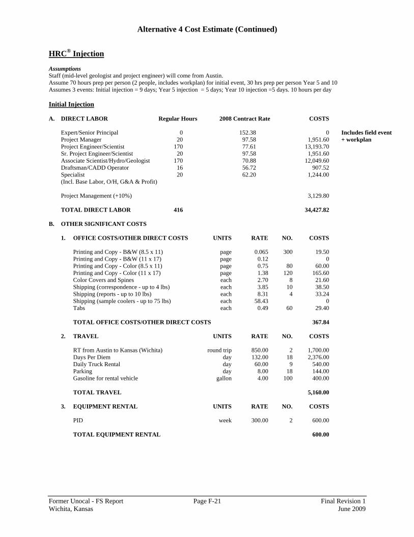
Alternative 4 Cost Estimate (Continued)
Former Unocal - FS Report Page F-21 Final Revision 1 Wichita, Kansas June 2009
HRC® Injection Assumptions Staff (mid-level geologist and project engineer) will come from Austin. Assume 70 hours prep per person (2 people, includes workplan) for initial event, 30 hrs prep per person Year 5 and 10 Assumes 3 events: Initial injection = 9 days; Year 5 injection = 5 days; Year 10 injection =5 days. 10 hours per day Initial Injection A. DIRECT LABOR Regular Hours 2008 Contract Rate COSTS
Expert/Senior Principal 0 152.38 0 Includes field event Project Manager 20 97.58 1,951.60 + workplan Project Engineer/Scientist 170 77.61 13,193.70 Sr. Project Engineer/Scientist 20 97.58 1,951.60 Associate Scientist/Hydro/Geologist 170 70.88 12,049.60 Draftsman/CADD Operator 16 56.72 907.52 Specialist 20 62.20 1,244.00 (Incl. Base Labor, O/H, G&A & Profit) Project Management (+10%) 3,129.80
TOTAL DIRECT LABOR 416 34,427.82
B. OTHER SIGNIFICANT COSTS
1. OFFICE COSTS/OTHER DIRECT COSTS UNITS RATE NO. COSTS
Printing and Copy - B&W (8.5 x 11) page 0.065 300 19.50 Printing and Copy - B&W (11 x 17) page 0.12 0 Printing and Copy - Color (8.5 x 11) page 0.75 80 60.00 Printing and Copy - Color (11 x 17) page 1.38 120 165.60 Color Covers and Spines each 2.70 8 21.60 Shipping (correspondence - up to 4 lbs) each 3.85 10 38.50 Shipping (reports - up to 10 lbs) each 8.31 4 33.24 Shipping (sample coolers - up to 75 lbs) each 58.43 0 Tabs each 0.49 60 29.40
TOTAL OFFICE COSTS/OTHER DIRECT COSTS 367.84
2. TRAVEL UNITS RATE NO. COSTS
RT from Austin to Kansas (Wichita) round trip 850.00 2 1,700.00 Days Per Diem day 132.00 18 2,376.00 Daily Truck Rental day 60.00 9 540.00 Parking day 8.00 18 144.00 Gasoline for rental vehicle gallon 4.00 100 400.00
TOTAL TRAVEL 5,160.00
3. EQUIPMENT RENTAL UNITS RATE NO. COSTS
PID week 300.00 2 600.00
TOTAL EQUIPMENT RENTAL 600.00
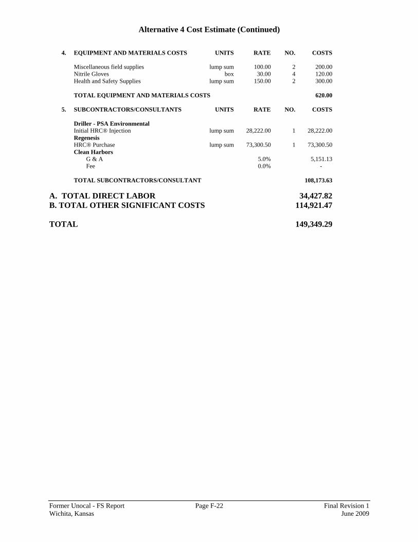
Alternative 4 Cost Estimate (Continued)
Former Unocal - FS Report Page F-22 Final Revision 1 Wichita, Kansas June 2009
4. EQUIPMENT AND MATERIALS COSTS UNITS RATE NO. COSTS
Miscellaneous field supplies lump sum 100.00 2 200.00 Nitrile Gloves box 30.00 4 120.00 Health and Safety Supplies lump sum 150.00 2 300.00
TOTAL EQUIPMENT AND MATERIALS COSTS 620.00
5. SUBCONTRACTORS/CONSULTANTS UNITS RATE NO. COSTS
Driller - PSA Environmental Initial HRC® Injection lump sum 28,222.00 1 28,222.00 Regenesis HRC® Purchase lump sum 73,300.50 1 73,300.50 Clean Harbors
G & A 5.0% 5,151.13 Fee 0.0% -
TOTAL SUBCONTRACTORS/CONSULTANT 108,173.63
A. TOTAL DIRECT LABOR 34,427.82 B. TOTAL OTHER SIGNIFICANT COSTS 114,921.47 TOTAL 149,349.29
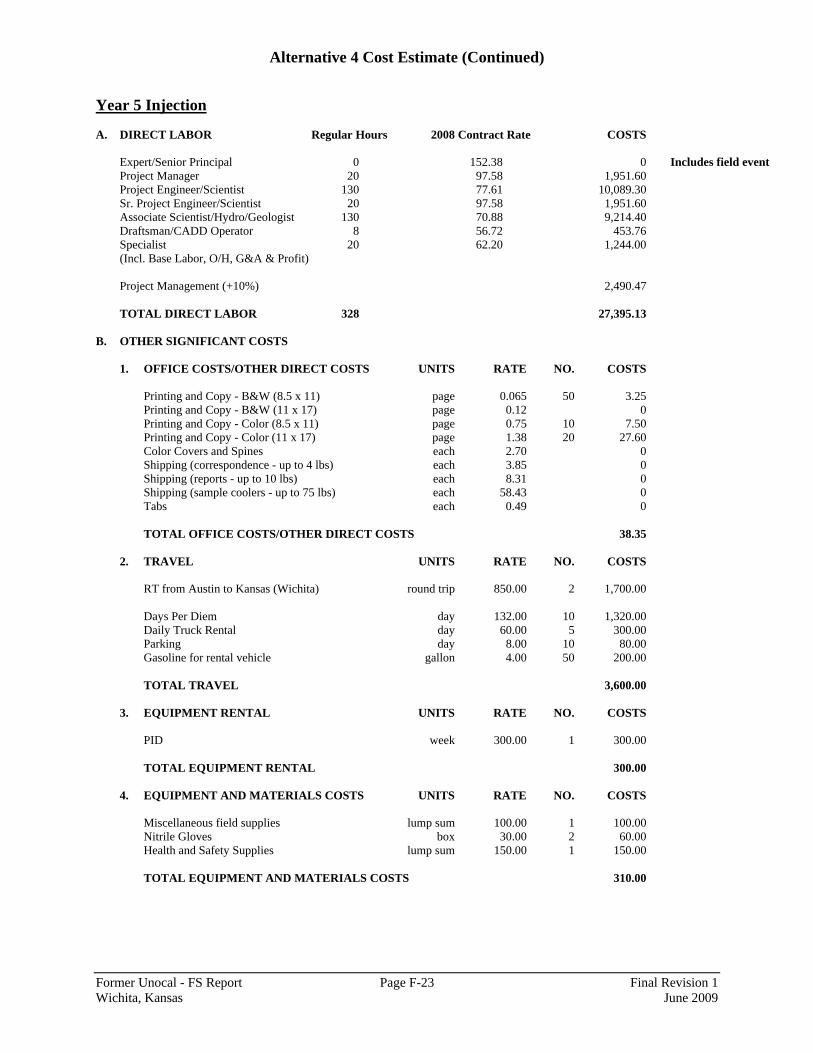
Alternative 4 Cost Estimate (Continued)
Former Unocal - FS Report Page F-23 Final Revision 1 Wichita, Kansas June 2009
Year 5 Injection A. DIRECT LABOR Regular Hours 2008 Contract Rate COSTS
Expert/Senior Principal 0 152.38 0 Includes field event Project Manager 20 97.58 1,951.60 Project Engineer/Scientist 130 77.61 10,089.30 Sr. Project Engineer/Scientist 20 97.58 1,951.60 Associate Scientist/Hydro/Geologist 130 70.88 9,214.40 Draftsman/CADD Operator 8 56.72 453.76 Specialist 20 62.20 1,244.00 (Incl. Base Labor, O/H, G&A & Profit) Project Management (+10%) 2,490.47
TOTAL DIRECT LABOR 328 27,395.13
B. OTHER SIGNIFICANT COSTS
1. OFFICE COSTS/OTHER DIRECT COSTS UNITS RATE NO. COSTS
Printing and Copy - B&W (8.5 x 11) page 0.065 50 3.25 Printing and Copy - B&W (11 x 17) page 0.12 0 Printing and Copy - Color (8.5 x 11) page 0.75 10 7.50 Printing and Copy - Color (11 x 17) page 1.38 20 27.60 Color Covers and Spines each 2.70 0 Shipping (correspondence - up to 4 lbs) each 3.85 0 Shipping (reports - up to 10 lbs) each 8.31 0 Shipping (sample coolers - up to 75 lbs) each 58.43 0 Tabs each 0.49 0
TOTAL OFFICE COSTS/OTHER DIRECT COSTS 38.35
2. TRAVEL UNITS RATE NO. COSTS
RT from Austin to Kansas (Wichita) round trip 850.00 2 1,700.00 Days Per Diem day 132.00 10 1,320.00 Daily Truck Rental day 60.00 5 300.00 Parking day 8.00 10 80.00 Gasoline for rental vehicle gallon 4.00 50 200.00 TOTAL TRAVEL 3,600.00
3. EQUIPMENT RENTAL UNITS RATE NO. COSTS
PID week 300.00 1 300.00
TOTAL EQUIPMENT RENTAL 300.00
4. EQUIPMENT AND MATERIALS COSTS UNITS RATE NO. COSTS
Miscellaneous field supplies lump sum 100.00 1 100.00 Nitrile Gloves box 30.00 2 60.00 Health and Safety Supplies lump sum 150.00 1 150.00 TOTAL EQUIPMENT AND MATERIALS COSTS 310.00
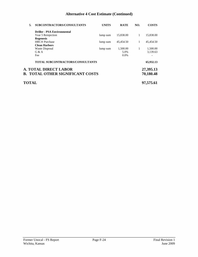
Alternative 4 Cost Estimate (Continued)
Former Unocal - FS Report Page F-24 Final Revision 1 Wichita, Kansas June 2009
5. SUBCONTRACTORS/CONSULTANTS UNITS RATE NO. COSTS
Driller - PSA Environmental Year 5 Reinjection lump sum 15,838.00 1 15,838.00 Regenesis HRC® Purchase lump sum 45,454.50 1 45,454.50 Clean Harbors Waste Disposal lump sum 1,500.00 1 1,500.00 G & A 5.0% 3,139.63 Fee 0.0% -
TOTAL SUBCONTRACTORS/CONSULTANTS 65,932.13
A. TOTAL DIRECT LABOR 27,395.13 B. TOTAL OTHER SIGNIFICANT COSTS 70,180.48 TOTAL 97,575.61

Alternative 4 Cost Estimate (Continued)
Former Unocal - FS Report Page F-25 Final Revision 1 Wichita, Kansas June 2009
Year 10 Injection A. DIRECT LABOR Regular Hours 2008 Contract Rate COSTS
Expert/Senior Principal 0 152.38 0 Project Manager 20 97.58 1,951.60 Includes field event Project Engineer/Scientist 130 77.61 10,089.30 Sr. Project Engineer/Scientist 20 97.58 1,951.60 Associate Scientist/Hydro/Geologist 130 70.88 9,214.40 Draftsman/CADD Operator 8 56.72 453.76 Specialist 20 62.20 1,244.00 (Incl. Base Labor, O/H, G&A & Profit) Project Management (+10%) 2,490.47
TOTAL DIRECT LABOR 328 27,395.13
B. OTHER SIGNIFICANT COSTS
1. OFFICE COSTS/OTHER DIRECT COSTS UNITS RATE NO. COSTS
Printing and Copy - B&W (8.5 x 11) page 0.065 50 3.25 Printing and Copy - B&W (11 x 17) page 0.12 0 Printing and Copy - Color (8.5 x 11) page 0.75 10 7.50 Printing and Copy - Color (11 x 17) page 1.38 20 27.60 Color Covers and Spines each 2.70 0 Shipping (correspondence - up to 4 lbs) each 3.85 0 Shipping (reports - up to 10 lbs) each 8.31 0 Shipping (sample coolers - up to 75 lbs) each 58.43 0 Tabs each 0.49 0 TOTAL OFFICE COSTS/OTHER DIRECT COSTS 38.35
2. TRAVEL UNITS RATE NO. COSTS
RT from Austin to Kansas (Wichita) round trip 850.00 2 1,700.00 Days Per Diem day 132.00 10 1,320.00 Daily Truck Rental day 60.00 5 300.00 Parking day 8.00 10 80.00 Gasoline for rental vehicle gallon 4.00 50 200.00
TOTAL TRAVEL 3,600.00
3. EQUIPMENT RENTAL UNITS RATE NO. COSTS
PID week 300.00 1 300.00
TOTAL EQUIPMENT RENTAL 300.00
4. EQUIPMENT AND MATERIALS COSTS UNITS RATE NO. COSTS
Miscellaneous field supplies lump sum 100.00 1 100.00 Nitrile Gloves box 30.00 2 60.00 Health and Safety Supplies lump sum 150.00 1 150.00
TOTAL EQUIPMENT AND MATERIALS COSTS 310.00

Alternative 4 Cost Estimate (Continued)
Former Unocal - FS Report Page F-26 Final Revision 1 Wichita, Kansas June 2009
5. SUBCONTRACTORS/CONSULTANTS UNITS RATE NO. COSTS
Driller - PSA Environmental Year 10 Reinjection lump sum 15,838.00 1 15,838.00 Regenesis HRC® Purchase lump sum 45,454.50 1 45,454.50 Clean Harbors Waste Disposal lump sum 1,500.00 1 1,500.00
G & A 5.0% 3,139.63 Fee 0.0% -
TOTAL SUBCONTRACTORS/CONSULTANTS 65,932.13
A. TOTAL DIRECT LABOR 27,395.13 B. TOTAL OTHER SIGNIFICANT COSTS 70,180.48 TOTAL 97,575.61

Alternative 4 Cost Estimate (Continued)
Former Unocal - FS Report Page F-27 Final Revision 1 Wichita, Kansas June 2009
Phytoremediation Installation Assumptions Staff (mid-level geologist and project engineer) will come from Austin. Assume workplan is covered by above HRC® estimate Assume 13 days total for phyto install, 10 hours per day Assume that it is linked with HRC® injection so no mob/demob for URS or driller A. DIRECT LABOR Regular Hours 2008 Contract Rate COSTS
Expert/Senior Principal 0 152.38 0 Project Manager 16 97.58 1,561.28 Includes field event Project Engineer/Scientist 130 77.61 10,089.30 only Sr. Project Engineer/Scientist 8 97.58 780.64 Associate Scientist/Hydro/Geologist 130 70.88 9,214.40 Draftsman/CADD Operator 4 56.72 226.88 Specialist 16 62.20 995.20 (Incl. Base Labor, O/H, G&A & Profit) Project Management (+10%) 2,286.77 TOTAL DIRECT LABOR 304 25,154.47
B. OTHER SIGNIFICANT COSTS
1. OFFICE COSTS/OTHER DIRECT COSTS UNITS RATE NO. COSTS
Printing and Copy - B&W (8.5 x 11) page 0.065 50 3.25 Printing and Copy - B&W (11 x 17) page 0.12 0 Printing and Copy - Color (8.5 x 11) page 0.75 10 7.50 Printing and Copy - Color (11 x 17) page 1.38 20 27.60 Color Covers and Spines each 2.70 0 Shipping (correspondence - up to 4 lbs) each 3.85 0 Shipping (reports - up to 10 lbs) each 8.31 0 Shipping (sample coolers - up to 75 lbs) each 58.43 0 Tabs each 0.49 0
TOTAL OFFICE COSTS/OTHER DIRECT COSTS 38.35
2. TRAVEL UNITS RATE NO. COSTS
RT from Austin to Kansas (Wichita) round trip 850.00 0 Days Per Diem day 132.00 26 3,432.00 Daily Truck Rental day 60.00 13 780.00 Parking day 8.00 26 208.00 Gasoline for rental vehicle gallon 4.00 150 600.00 TOTAL TRAVEL 5,020.00
3. EQUIPMENT RENTAL UNITS RATE NO. COSTS
PID week 300.00 2 600.00
TOTAL EQUIPMENT RENTAL 600.00
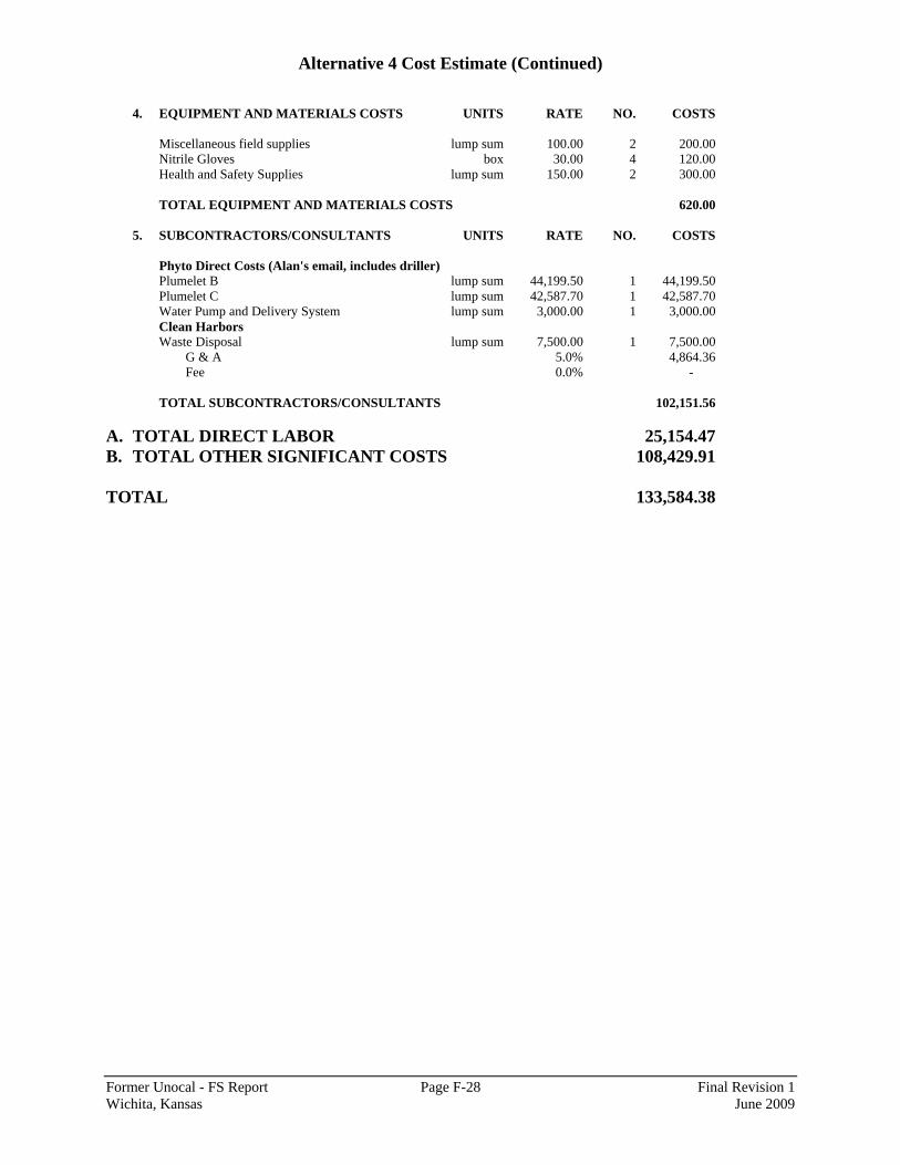
Alternative 4 Cost Estimate (Continued)
Former Unocal - FS Report Page F-28 Final Revision 1 Wichita, Kansas June 2009
4. EQUIPMENT AND MATERIALS COSTS UNITS RATE NO. COSTS
Miscellaneous field supplies lump sum 100.00 2 200.00 Nitrile Gloves box 30.00 4 120.00 Health and Safety Supplies lump sum 150.00 2 300.00
TOTAL EQUIPMENT AND MATERIALS COSTS 620.00
5. SUBCONTRACTORS/CONSULTANTS UNITS RATE NO. COSTS
Phyto Direct Costs (Alan's email, includes driller) Plumelet B lump sum 44,199.50 1 44,199.50 Plumelet C lump sum 42,587.70 1 42,587.70 Water Pump and Delivery System lump sum 3,000.00 1 3,000.00 Clean Harbors Waste Disposal lump sum 7,500.00 1 7,500.00
G & A 5.0% 4,864.36 Fee 0.0% -
TOTAL SUBCONTRACTORS/CONSULTANTS 102,151.56
A. TOTAL DIRECT LABOR 25,154.47 B. TOTAL OTHER SIGNIFICANT COSTS 108,429.91 TOTAL 133,584.38
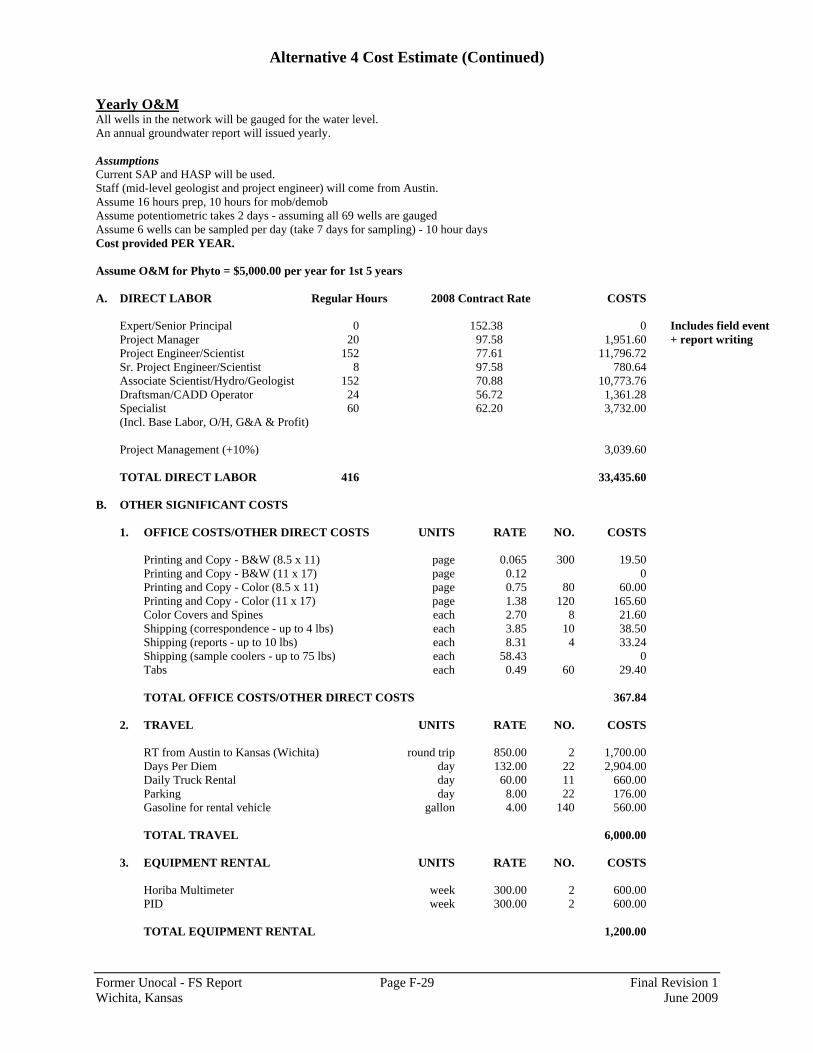
Alternative 4 Cost Estimate (Continued)
Former Unocal - FS Report Page F-29 Final Revision 1 Wichita, Kansas June 2009
Yearly O&M All wells in the network will be gauged for the water level. An annual groundwater report will issued yearly. Assumptions Current SAP and HASP will be used. Staff (mid-level geologist and project engineer) will come from Austin. Assume 16 hours prep, 10 hours for mob/demob Assume potentiometric takes 2 days - assuming all 69 wells are gauged Assume 6 wells can be sampled per day (take 7 days for sampling) - 10 hour days Cost provided PER YEAR. Assume O&M for Phyto = $5,000.00 per year for 1st 5 years A. DIRECT LABOR Regular Hours 2008 Contract Rate COSTS
Expert/Senior Principal 0 152.38 0 Includes field event Project Manager 20 97.58 1,951.60 + report writing Project Engineer/Scientist 152 77.61 11,796.72 Sr. Project Engineer/Scientist 8 97.58 780.64 Associate Scientist/Hydro/Geologist 152 70.88 10,773.76 Draftsman/CADD Operator 24 56.72 1,361.28 Specialist 60 62.20 3,732.00 (Incl. Base Labor, O/H, G&A & Profit) Project Management (+10%) 3,039.60
TOTAL DIRECT LABOR 416 33,435.60
B. OTHER SIGNIFICANT COSTS
1. OFFICE COSTS/OTHER DIRECT COSTS UNITS RATE NO. COSTS
Printing and Copy - B&W (8.5 x 11) page 0.065 300 19.50 Printing and Copy - B&W (11 x 17) page 0.12 0 Printing and Copy - Color (8.5 x 11) page 0.75 80 60.00 Printing and Copy - Color (11 x 17) page 1.38 120 165.60 Color Covers and Spines each 2.70 8 21.60 Shipping (correspondence - up to 4 lbs) each 3.85 10 38.50 Shipping (reports - up to 10 lbs) each 8.31 4 33.24 Shipping (sample coolers - up to 75 lbs) each 58.43 0 Tabs each 0.49 60 29.40
TOTAL OFFICE COSTS/OTHER DIRECT COSTS 367.84
2. TRAVEL UNITS RATE NO. COSTS
RT from Austin to Kansas (Wichita) round trip 850.00 2 1,700.00 Days Per Diem day 132.00 22 2,904.00 Daily Truck Rental day 60.00 11 660.00 Parking day 8.00 22 176.00 Gasoline for rental vehicle gallon 4.00 140 560.00 TOTAL TRAVEL 6,000.00
3. EQUIPMENT RENTAL UNITS RATE NO. COSTS
Horiba Multimeter week 300.00 2 600.00 PID week 300.00 2 600.00
TOTAL EQUIPMENT RENTAL 1,200.00
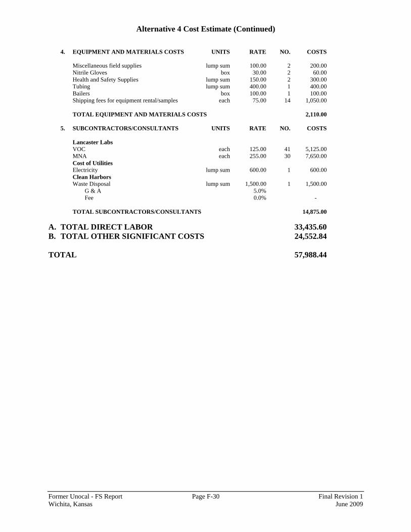
Alternative 4 Cost Estimate (Continued)
Former Unocal - FS Report Page F-30 Final Revision 1 Wichita, Kansas June 2009
4. EQUIPMENT AND MATERIALS COSTS UNITS RATE NO. COSTS
Miscellaneous field supplies lump sum 100.00 2 200.00 Nitrile Gloves box 30.00 2 60.00 Health and Safety Supplies lump sum 150.00 2 300.00 Tubing lump sum 400.00 1 400.00 Bailers box 100.00 1 100.00 Shipping fees for equipment rental/samples each 75.00 14 1,050.00
TOTAL EQUIPMENT AND MATERIALS COSTS 2,110.00
5. SUBCONTRACTORS/CONSULTANTS UNITS RATE NO. COSTS
Lancaster Labs VOC each 125.00 41 5,125.00 MNA each 255.00 30 7,650.00 Cost of Utilities Electricity lump sum 600.00 1 600.00 Clean Harbors Waste Disposal lump sum 1,500.00 1 1,500.00
G & A 5.0% Fee 0.0% -
TOTAL SUBCONTRACTORS/CONSULTANTS 14,875.00
A. TOTAL DIRECT LABOR 33,435.60 B. TOTAL OTHER SIGNIFICANT COSTS 24,552.84 TOTAL 57,988.44

Attachment A Alternative 4 HRC® Cost Estimate
Former Unocal - FS Report Page F-31 Final Revision 1 Wichita, Kansas June 2009
Plumelet A Barrier #1 - 75 feet long, 9 - 40 ft bgs Number of injection points - 16 HRC® Dosing Rate - ~11 pounds per foot (or 1 gallon per foot) for first 5 feet above the
refusal depth then 5 pounds per foot (or 0.5 gallons per foot) until above the water table.
Injection length 31 ft HRC®use per point 185 lbs/point Total HRC use 2,960 lbs Barrier #2 - 50 feet long, 22-30 ft bgs Number of injection points - 11 HRC®Dosing Rate - ~11 pounds per foot (or 1 gallon per foot) for first 5 feet above the
refusal depth then 5 pounds per foot (or 0.5 gallons per foot) until above the water table.
Injection length 8 ft HRC®use per point 70 lbs/point Total HRC®use 770 lbs Barrier #3 - 125 feet long, 9 - 40 ft bgs Number of injection points - 26 HRC®Dosing Rate - ~11 pounds per foot (or 1 gallon per foot) for first 5 feet above the
refusal depth then 5 pounds per foot (or 0.5 gallons per foot) until above the water table.
Injection length 31 ft HRC®use per point 185 lbs/point Total HRC®use 4,810 lbs Total HRC® Use for Plumelet A 8,540 lbs Plumelet B Barriers #1 & 2 - 50 feet long, 15 - 30 ft bgs Number of injection points - 22 HRC®Dosing Rate - ~11 pounds per foot (or 1 gallon per foot) for first 5 feet above the
refusal depth then 5 pounds per foot (or 0.5 gallons per foot) until above the water table.
Injection length 15 ft HRC®use per point 105 lbs/point Total HRC®use 2,310 lbs Barrier #3 - 100 feet long, 17 - 27 ft bgs Number of injection points - 21 HRC®Dosing Rate - ~11 pounds per foot (or 1 gallon per foot) for first 5 feet above the
refusal depth then 5 pounds per foot (or 0.5 gallons per foot) until above the water table.
Injection length 10 ft HRC®use per point 80 lbs/point Total HRC®use 1,680 lbs Total HRC®Use for Plumelet B 3,990 lbs
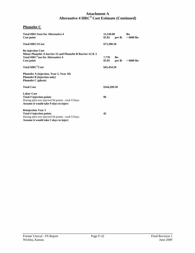
Attachment A Alternative 4 HRC® Cost Estimate (Continued)
Former Unocal - FS Report Page F-32 Final Revision 1 Wichita, Kansas June 2009
Plumelet C Total HRC®use for Alternative 4 12,530.00 lbs Cost point $5.85 per lb > 6000 lbs Total HRC®Cost $73,300.50 Re-injection Cost Minus Plumelet A barrier #2 and Plumelet B Barrier #2 & 3 Total HRC®use for Alternative 4 7,770 lbs Cost point $5.85 per lb > 6000 lbs Total HRC®Cost $45,454.50 Plumelet A (injection, Year 5, Year 10) Plumelet B (injection only) Plumelet C (phyto) Total Cost $164,209.50 Labor Cost Total # injection points 96 During pilot test injected 94 points - took 9 Days Assume it would take 9 days to inject Reinjection Year 5 Total # injection points 42 During pilot test injected 94 points - took 9 Days Assume it would take 5 days to inject