Final Report for - St. Petersburg, Florida Report for August 8, 2014 City of St. Petersburg –...
35
Final Report for
Transcript of Final Report for - St. Petersburg, Florida Report for August 8, 2014 City of St. Petersburg –...

Final Report for

August 8, 2014
City of St. Petersburg – Municipal Pier Building Structure and
Substructure Evaluation
City Project Number: 12212-117
i
Executive Summary
This report evaluates the existing condition of the Municipal Pier building structure (and
supporting substructure caissons) in St. Petersburg, Florida. In order to determine the
feasibility of refurbishing the building by reusing its current structural components,
assessment included field review, materials testing, and evaluation of previous
documentation and studies.
Based on the findings of our team, the following conclusions are presented:
Current building code requirements dictate a significant increase in design wind loading
well above that of the original design which could require strengthening or reconstruction
of the existing structural system for compliance.
Current building code requirements may impede usage of the first floor of a refurbished
building due to flood elevation design requirements.
Corrosion testing and analysis showed the existing steel structure related to the building
has limited corrosion activity. The reinforced concrete components of the building
structure have random areas of deterioration related to moisture and chloride intrusion.
Based on available data, the steel H piles of the caisson substructure appear to have
limited chloride exposure.
Consideration of access for necessary reconstruction of the supporting first floor
structural elements (that were part of the original pier design) would be a significant issue
due to interference from the surrounding structure.
An extension of the design life of the building structure for an additional 75 years would
greatly exceed that of similar coastal structures but could be achieved with repairs,
reconstruction, cathodic protection systems for steel components, any strengthening
requirements for the buildings structural systems, and first floor flood elevation
modifications for building code compliance.

City of St. Petersburg – Municipal Pier Building Structure and Substructure Evaluation
City Project Number: 12212-117
ii
Table of Contents Executive Summary ....................................................................................................... i
Table of Contents ........................................................................................................ ii
List of Figures.............................................................................................................. ii
List of Tables .............................................................................................................. iii
1.0 Introduction ......................................................................................................1
1.1 History ................................................................................................ 1
1.2 Scope of Services ................................................................................. 1
1.3 Documentation .................................................................................... 2
2.0 Condition Survey ...............................................................................................3
2.1 Structure Description ........................................................................... 3
2.2 Site Visit .............................................................................................. 3
2.3 Selective Demolition Structural Observations ...................................... 4
2.4 Elevator Shaft Structural Observations ................................................. 6
3.0 Wind Loading Analysis .......................................................................................7
4.0 Lightning Protection System ...............................................................................9
5.0 Corrosion Investigation .................................................................................... 10
5.1 Limits of Investigation ....................................................................... 10
5.2 Corrosion Investigation Results ......................................................... 12
6.0 Structural Conclusion ...................................................................................... 23
7.0 Recommendations ........................................................................................... 23
Appendix A………………………………………………………………………………………………27
Appendix B………………………………………………………………………………………………29
24
iii

City of St. Petersburg – Municipal Pier Building Structure and Substructure Evaluation
City Project Number: 12212-117
iii
List of Figures Figure 1: Inverted Pyramid Page 1
Figure 2: Caisson Layout Page 3
Figure 3: Demolition Page 4
Figure 4: Concrete Sample A Page 4
Figure 5: Concrete Sample B Page 4
Figure 6: Concrete Sample C Page 5
Figure 7: Concrete Sample C Page 5
Figure 8: Concrete Sample C Page 5
Figure 9: Concrete Sample D Page 6
Figure 10: Concrete Sample D Page 6
Figure 11: Concrete Sample D Page 6
Figure 12: 5th Floor Plan View Page 10
Figure 13: 5th Floor Damage SW Corner Page 12
Figure 14: Typical Deterioration Page 12
Figure 15: Elevator Pits Page 14
Figure 16: Exterior Damage Page 14
Figure 17: Exterior Damage Page 15
Figure 18: Exterior Damage SW Corner Page 16
Figure 19: Exterior Damage SW Corner Page 17
Figure 20: Chloride Content Results Page 19
Figure 21: Carbonation Depth Results Page 20
List of Tables
Table 1: Design Wind Pressures Page 8
Table 2: Location of Powder Samples Page 11
Table 3: Caisson Identification for VCS and McLaren Page 21

City of St. Petersburg – Municipal Pier Building Structure and Substructure Evaluation
City Project Number: 12212-117
1
Introduction
1.1 History
The St. Petersburg Municipal Pier (The Pier) was
constructed in 1926 and consists of
approximately 1,400 feet by 100 feet of
approach spans and a 420 foot by 300 foot pier
head at its eastern end. A five story inverted
pyramid building (Figure 1), the primary subject
of this report, was built within the pier head in
1973. Additions consisting of a first level retail
space build out and an exterior west elevator
were constructed in 1987.
On May 31, 2013 the pier was closed to all commerce and non-essential vehicular traffic due to
deterioration of primary structural components throughout the approach spans and portions of the pier
head. The design of a replacement pier, called “The Lens”, had been approved by the St. Petersburg City
Council and was in the developmental stages before a citizen-driven referendum in August, 2013 halted
the progress.
Upon taking office in 2014, Mayor Rick Kriseman asked that security fences be removed and that the pier
approaches and pier head be open to the public for pedestrian access, fishing and other related activities.
At the time of this report, the pier is open to pedestrian traffic and essential vehicular traffic that is
required for pier maintenance but the building remains closed to the public.
1.2 Scope of Services
While there is little question that the original pier structural components have reached the end of their
useful service life based on previous investigations, there has been recent discussion regarding the
possibility of restoring the inverted pyramid and incorporating it into a new pier concept. The Scope of
Services required for this report was to perform an inspection of the existing inverted pyramid structure
and the foundation elements associated with it and make a recommendation to the City regarding the
feasibility of restoration.
Specific services performed by the engineering team included:
Inspection and evaluation of the inverted pyramid structure
Inspection and evaluation of the caissons
Figure 1: Inverted pyramid
City of St. Petersburg – Municipal Pier Building Structure and Substructure Evaluation
City Project Number: 12212-117
2
Removal of concrete material for visual inspection of internal components and strength and chloride
testing (including repair of the sample excavation sites)
Evaluation of current Building Code requirements as compared to the 1973 design code
Estimation of the remaining service life of the inverted pyramid structure and foundation
Recommendation of measures to extend the service life of the pyramid structure and foundation
Prepare of a summary of findings report
1.3 Documentation
The following documentation was provided by the City of St. Petersburg (the City):
Pier Development Project architectural drawings prepared by Harvard and Jolly, A.I.A., dated
March 2, 1970.
Pier Development Project structural drawings prepared by Erwin Reiss, dated March 2, 1970.
First Floor Retail Structure & Elevator Addition – St. Petersburg Municipal Pier Improvements
architectural drawings prepared by Sasaki Associates, Inc., dated March 10, 1987.
St. Petersburg Municipal Pier Improvements structural drawings prepared by O.E. Olsen &
Associates, dated July 23, 1987. • Saint Petersburg Municipal Pier, Alternatives Study, Parsons
Brinckerhoff, May 2003.
St. Petersburg Pier Existing Caisson Inspection, McLaren Engineering Group, February 2013.
Environmental Forces Study, McLaren Engineering Group, April 2013.
Results of Petrographic Examinations and Laboratory Testing of Concrete Cores, Terracon
Consultants, Inc., August 2013.
St. Petersburg Pier Remaining Service Life Caissons and Steel Frame, Karins Engineering Group,
Inc., May 2014.

City of St. Petersburg – Municipal Pier Building Structure and Substructure Evaluation
City Project Number: 12212-117
3
Condition Survey
2.1 Structure Description
The St. Petersburg Municipal Pier was constructed in 1926. In
1973 an inverted pyramid structure and four supporting
caissons (Figure 2) were added to the pier. In 1986 a fifth
caisson supporting an exterior elevator, identified as the west
caisson, was added to the pier. Each caisson is comprised of
twenty HP14x73 steel piles that are encapsulated in concrete
within a steel sheet pile cofferdam that serves as a stay-in-place
form. The primary foundation elements of the inverted pyramid
and additional elevator are structurally independent of the
original pier. The inverted pyramid is comprised of a steel frame
encased in concrete for fireproofing, corrosion protection, and
strength. The inverted pyramid’s first level floor structure
consists of a concrete pile/beam/slab system that was
constructed with the original pier in 1926. The remainder of the main structure consists of wide flange
steel beam and column construction. The floor system for the remainder of the structure consists of
reinforced cast-in-place (CIP) concrete slabs supported by the wide flange steel beams.
2.2 Site Visit
Out team performed a condition survey of The Pier on Tuesday, June 3, 2014. The assessment consisted
of an exterior perimeter survey accessed from the pier deck and roof of the first floor retail area and
included observations of the bottom portion of accessible elevator shafts and tops of caissons in the
shafts. The second assessment, June 25, 2014, consisted of selective demolition and a visual survey of
the upper portion of the beam on the southwest corner of the structure.
The selective demolition was completed by Vector Corrosion Services (VCS) in conjunction with material
sampling and testing. Biller Reinhart Structural Group, Inc. (Biller Reinhart) led the structural investigation
of the building.
Figure 2: Caisson layout

City of St. Petersburg – Municipal Pier Building Structure and Substructure Evaluation
City Project Number: 12212-117
4
2.3 Selective Demolition Structural Observations
Portions of the concrete encasement were removed from
the upper regions of the main beam at the southwest
corner of the structure. The purpose of the selective
demolition was to expose the underlying steel
components and observe the degree of corrosion present.
Observations from the selective demolition are as follows:
Sample Area A
A. Sample Area A was located in the center portion of
the bottom of the beam where concrete spalling
was observed (Figure 3).
B. The removed portion of the concrete in Sample
Area A (Figure 4).
C. The markings observed in the bottom flange of the
beam were due to tool impact during the removal
of the concrete.
D. Cracking in the concrete was observed to extend
from the surface of the encasement to steel flange.
E. Corrosion of the steel beam flange was not
observed in the sample area.
F. An isolated portion of the welded wire fabric
embedded in the concrete encasement was
observed to be corroded.
Sample Area B
A. Sample Area B was located at the edge of the
bottom flange of the beam.
Figure 3: Demolition
Figure 4: Concrete sample A
Figure 5: Concrete sample B

City of St. Petersburg – Municipal Pier Building Structure and Substructure Evaluation
City Project Number: 12212-117
5
B. The removed portion of the concrete in Sample
Area B (Figure 5).
C. The markings observed in the bottom flange of
the beam were due to tool impact during the
removal of the concrete.
D. Corrosion of the steel beam flange was not
observed in the sample area.
Sample Area C
A. Sample Area C was located at the intersection of
the diagonal corner beam and the fifth level
perimeter beam. Cracking in the concrete
encasement was present at the location of the
cracking.
B. The removed portion of the concrete (Figure 6).
C. The top flange of the exposed perimeter beam
(Figure 7). Surficial corrosion of the top flange was
observed.
D. Minor corrosion of an embedded reinforcement
bar was observed above the top flange of the
beam. Refer to (Figure 8).
E. The cracking in the concrete encasement of the
perimeter beam appeared to be occurring where
the encasement extended over the face of the
observation deck. Neither steel welded wire fabric
nor reinforcement bars were observed in this
section of the encasement. Such reinforcement is
to minimize the widths and extents of cracking in
concrete.
Sample Area D
A. Sample Area D was located in the center
of the top flange beam.
Figure 6: Concrete sample C
Figure 7: Concrete sample C
Figure 8: Concrete sample C
City of St. Petersburg – Municipal Pier Building Structure and Substructure Evaluation
City Project Number: 12212-117
6
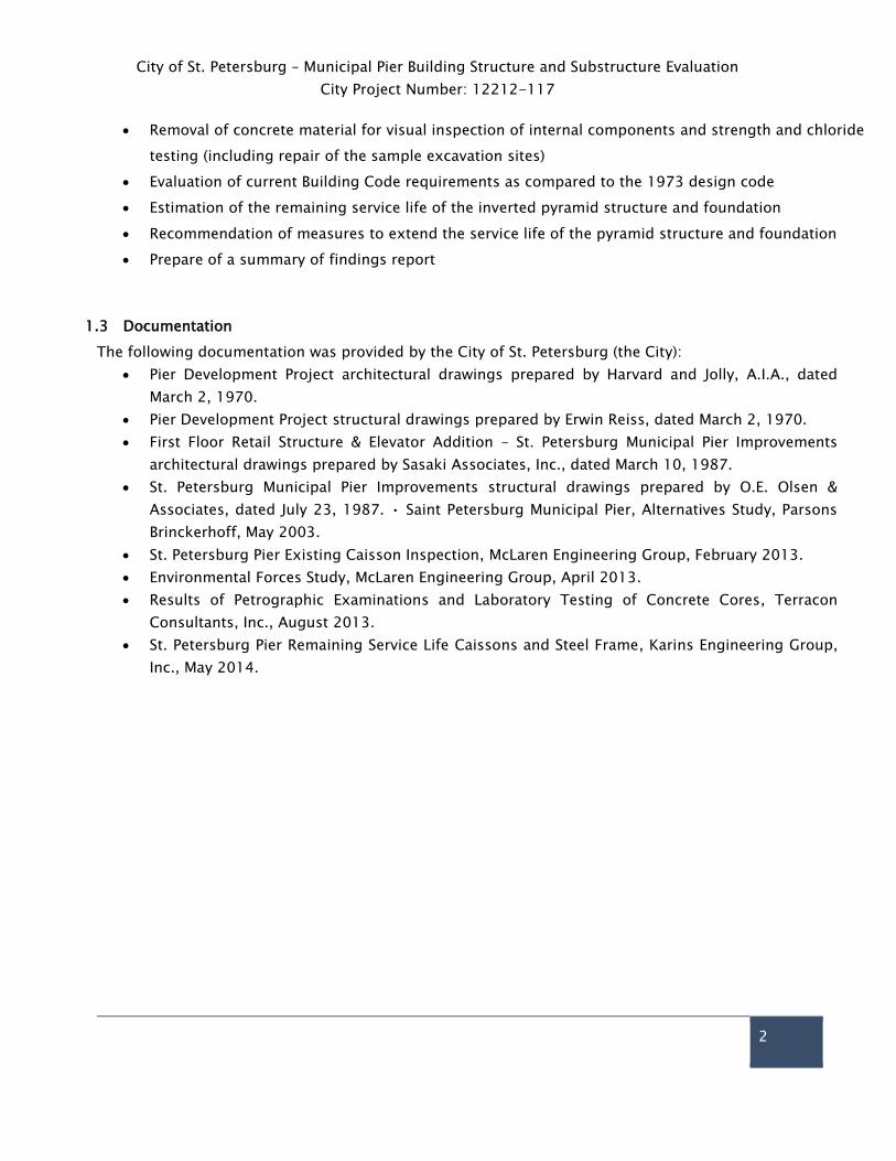
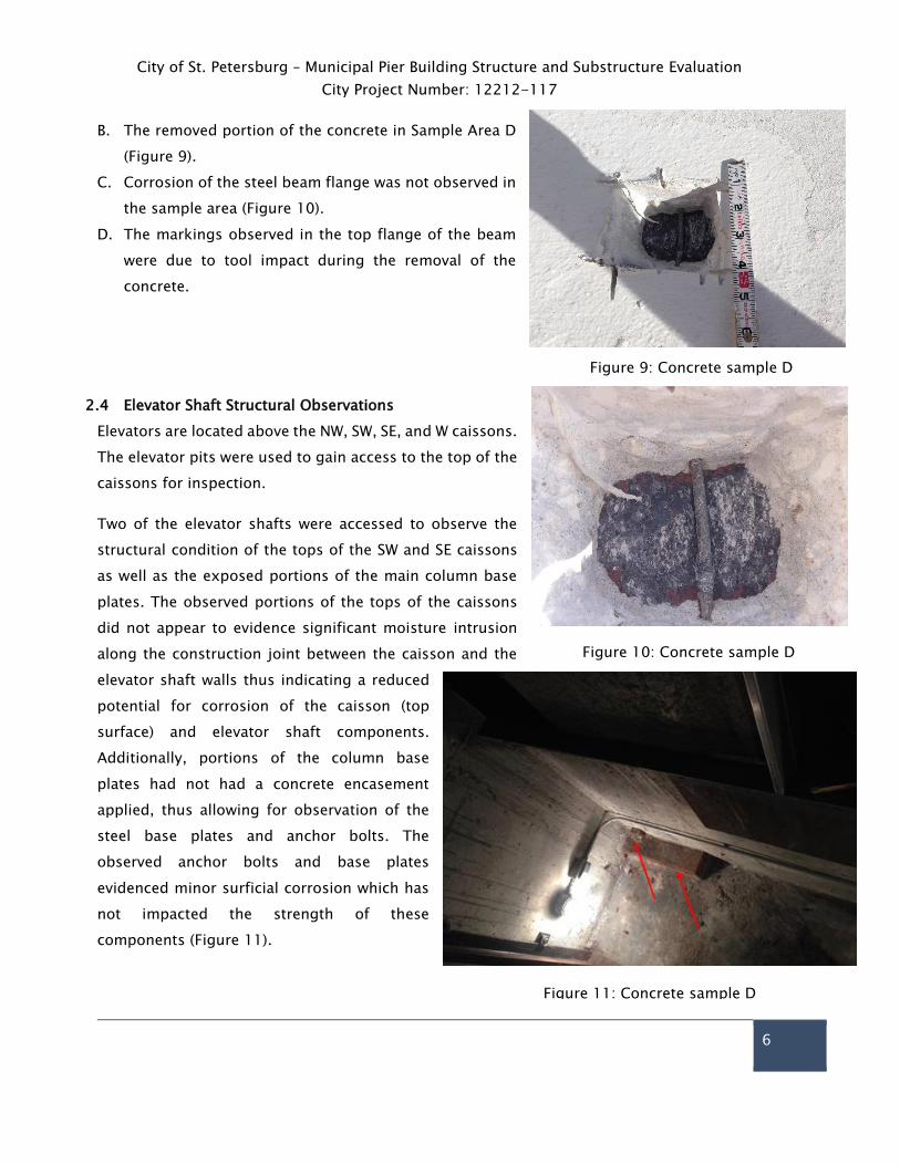
B. The removed portion of the concrete in Sample Area D
(Figure 9).
C. Corrosion of the steel beam flange was not observed in
the sample area (Figure 10).
D. The markings observed in the top flange of the beam
were due to tool impact during the removal of the
concrete.
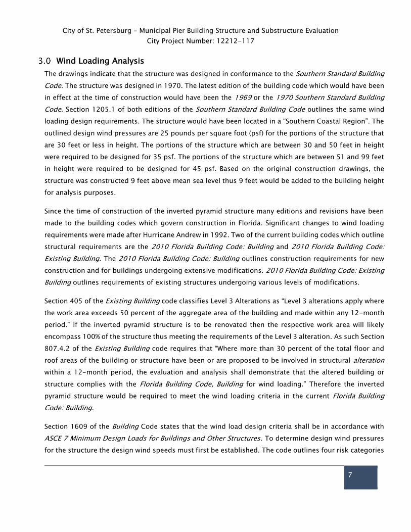
2.4 Elevator Shaft Structural Observations
Elevators are located above the NW, SW, SE, and W caissons.
The elevator pits were used to gain access to the top of the
caissons for inspection.
Two of the elevator shafts were accessed to observe the
structural condition of the tops of the SW and SE caissons
as well as the exposed portions of the main column base
plates. The observed portions of the tops of the caissons
did not appear to evidence significant moisture intrusion
along the construction joint between the caisson and the
elevator shaft walls thus indicating a reduced
potential for corrosion of the caisson (top
surface) and elevator shaft components.
Additionally, portions of the column base
plates had not had a concrete encasement
applied, thus allowing for observation of the
steel base plates and anchor bolts. The
observed anchor bolts and base plates
evidenced minor surficial corrosion which has
not impacted the strength of these
components (Figure 11).
Figure 9: Concrete sample D
Figure 10: Concrete sample D
Figure 11: Concrete sample D
City of St. Petersburg – Municipal Pier Building Structure and Substructure Evaluation
City Project Number: 12212-117
7
Wind Loading Analysis
The drawings indicate that the structure was designed in conformance to the Southern Standard Building
Code. The structure was designed in 1970. The latest edition of the building code which would have been
in effect at the time of construction would have been the 1969 or the 1970 Southern Standard Building
Code. Section 1205.1 of both editions of the Southern Standard Building Code outlines the same wind
loading design requirements. The structure would have been located in a “Southern Coastal Region”. The
outlined design wind pressures are 25 pounds per square foot (psf) for the portions of the structure that
are 30 feet or less in height. The portions of the structure which are between 30 and 50 feet in height
were required to be designed for 35 psf. The portions of the structure which are between 51 and 99 feet
in height were required to be designed for 45 psf. Based on the original construction drawings, the
structure was constructed 9 feet above mean sea level thus 9 feet would be added to the building height
for analysis purposes.
Since the time of construction of the inverted pyramid structure many editions and revisions have been
made to the building codes which govern construction in Florida. Significant changes to wind loading
requirements were made after Hurricane Andrew in 1992. Two of the current building codes which outline
structural requirements are the 2010 Florida Building Code: Building and 2010 Florida Building Code:
Existing Building. The 2010 Florida Building Code: Building outlines construction requirements for new
construction and for buildings undergoing extensive modifications. 2010 Florida Building Code: Existing
Building outlines requirements of existing structures undergoing various levels of modifications.
Section 405 of the Existing Building code classifies Level 3 Alterations as “Level 3 alterations apply where
the work area exceeds 50 percent of the aggregate area of the building and made within any 12-month
period.” If the inverted pyramid structure is to be renovated then the respective work area will likely
encompass 100% of the structure thus meeting the requirements of the Level 3 alteration. As such Section
807.4.2 of the Existing Building code requires that “Where more than 30 percent of the total floor and
roof areas of the building or structure have been or are proposed to be involved in structural alteration
within a 12-month period, the evaluation and analysis shall demonstrate that the altered building or
structure complies with the Florida Building Code, Building for wind loading.” Therefore the inverted
pyramid structure would be required to meet the wind loading criteria in the current Florida Building
Code: Building.
Section 1609 of the Building Code states that the wind load design criteria shall be in accordance with
ASCE 7 Minimum Design Loads for Buildings and Other Structures. To determine design wind pressures
for the structure the design wind speeds must first be established. The code outlines four risk categories

City of St. Petersburg – Municipal Pier Building Structure and Substructure Evaluation
City Project Number: 12212-117
8
for the determination of a design wind speed when given a structures geographic location. Table 1.5-1
of ASCE 7-10 outlines a “Risk Category III” as “Buildings and other structures, not included in Risk
Category IV, with potential to cause a substantial economic impact and/or mass disruption of day-to-
day civilian life in the event of failure.” Given the purpose of the structure, Biller Reinhart believes that
the structure would qualify as a Risk Category III structure as failure of the structure would result in a
substantial economic impact due to potential repairs and loss of a tourism generator for the surrounding
area. After discussions with City of St. Petersburg officials and in conjunction with the above outlined
rational, both Biller Reinhart and the City of St. Petersburg Building Official agree that the Risk Category
III classification is the appropriate classification and would be prudent for the long-term design of the
structure.
Based on a Risk Category III classification, the design wind speed for the structure would be 155 miles
per hour. As with the Southern Standard Building Code the current code design wind pressures increase
along the height of the structure. Current code increases however are done in 5 feet increments starting
at 15 feet and going up to 30 feet and are in 10 foot increments thereafter. Given the design wind speed
and assuming the window assemblies of the structure would be upgraded to impact resistant windows,
the design wind pressures for the structure per the original and current building codes are as follows:
Table 1: Design Wind Pressures
Height of Structure
(ft)
Original Design
Pressure (psf)
Current Design
Pressure (psf)
Percent
Increase (%)
0-15 25 53.2 113
16-20 25 54.4 118
21-25 25 55.2 121
26-30 35 56.0 60
31-40 35 57.3 64
41-50 35 58.4 67
51-60 45 59.2 32
61-70 45 59.9 33
With the substantial increase in design wind pressure loading when comparing current code requirements
to original construction load requirements, a detailed analysis of the structure would be required to
determine if the existing structure is capable of withstanding the code required design wind pressures.
If the analysis indicates that the existing structure is incapable of withstanding the current code
requirements, then an extensive strengthening of the connections and components would be necessary
for the structure to meet current building code requirements. Strengthening of the steel structure would
likely include removal of the concrete beam and column encasements to provide access to the steel

City of St. Petersburg – Municipal Pier Building Structure and Substructure Evaluation
City Project Number: 12212-117
9
members and connections, field welding supplemental steel plates and/or sections to the existing
members and connections, and possible supplemental steel sections being added to the existing
structural steel frame.
Lightning Protection System
Although an in-depth discussion of lightning protection systems is not within the scope of this report,
a brief comment is provided for future consideration of any long-term planned use of the existing
building structure. An independent system comprised of external protection should be designed by
experienced engineers. This protection may consist of rods, conductor cables, and ground rods to
provide a designated path to the ground for lightning. Preventing fire, building material damage,
“flashes” across rooms, destruction of electrical appliances, and injury to occupants is an important part
of modern building design in regions subject to high frequency lightning strikes.

City of St. Petersburg – Municipal Pier Building Structure and Substructure Evaluation
City Project Number: 12212-117
10
Corrosion Investigation
5.1 Limits of Investigation
The preliminary corrosion investigation included a complete visual inspection of the inverted pyramid
structure, both interior and exterior. The visual inspection included hammer sounding for delaminations
in areas in which the structural components were exposed and accessible. Access to the pyramid exterior
was limited due to the surrounding pier’s condition. The original pier structure is experiencing significant
levels of deterioration, therefore load restrictions have been incorporated. As a result, access to the
exterior structure above the 2nd floor was limited because an aerial lift large enough to access the upper
reaches of the structure was too heavy for the pier. A larger aerial lift was used on the west face of the
structure because this area has a greater load carrying capacity. The exterior inspection was completed
primarily from the roof of the first floor structure surrounding the pyramid.
Each diagonal column of the inverted pyramid structure was
given an identification number so that information regarding
the diagonals and other structural members could be
referenced to a known coordinate system. A plan view of the
pyramid’s 5th floor is provided along with the label for each
diagonal member (Figure 12). The northeast (NE) corner of the
structure was set as the zero diagonal and subsequent
diagonals numbered sequentially in the clock-wise direction.
All exterior components of the pyramid are hereafter referenced
to the diagonals and the floor number.
Concrete powder samples were collected throughout the
structure to identify the amount of chloride that had penetrated
into the concrete matrix. Concrete powder samples were collected in 14 locations; in the beams, columns,
diagonals, and the SE elevator pit (Table 2). The samples were collected primarily on the exterior of the
structure, since this was the most susceptible area to chloride contamination. However, several samples
were also collected on the interior of the structure to verify that the interior was not exposed to chloride
contamination. The powder samples were collected using a hammer drill with a ¾ in. diameter drill bit.
The resulting concrete powder was collected and sealed in a plastic bag. The powder samples were
collected in ½ inch depth increments starting at the surface and extended 2 inches deep. In two sampling
locations (diagonals 30 and 32) steel was encountered prior to reaching the 2 in. depth, therefore drilling
was stopped.
Figure 12: 5th Floor Plan View

City of St. Petersburg – Municipal Pier Building Structure and Substructure Evaluation
City Project Number: 12212-117
11
Table 2: Location of powder samples
Member Location Reference Diagonal
Location Floor Building Face
Beam Web Between 8 & 9 2 East
Beam Web Between 20 & 21 5 West
Beam Web Between 31 & 32 4 North
Beam Bottom Flange Between 31 & 32 5 North
Column Flange 0 2 Northeast
Column Flange 10 2 Southeast
Diagonal Bottom Flange 0 2 Northeast
Diagonal Bottom Flange 10 2 Southeast
Diagonal Bottom Flange 20 5 Southwest
Diagonal* Bottom Flange 25 4 West
Diagonal Bottom Flange 29 4 West
Diagonal+ Web 30 4 Northwest
Diagonal+ Web 32 4 North
Elevator
Pit* Base of East Wall
- 1 Southeast
* Interior sample +Encountered steel during collection
City of St. Petersburg – Municipal Pier Building Structure and Substructure Evaluation
City Project Number: 12212-117
12
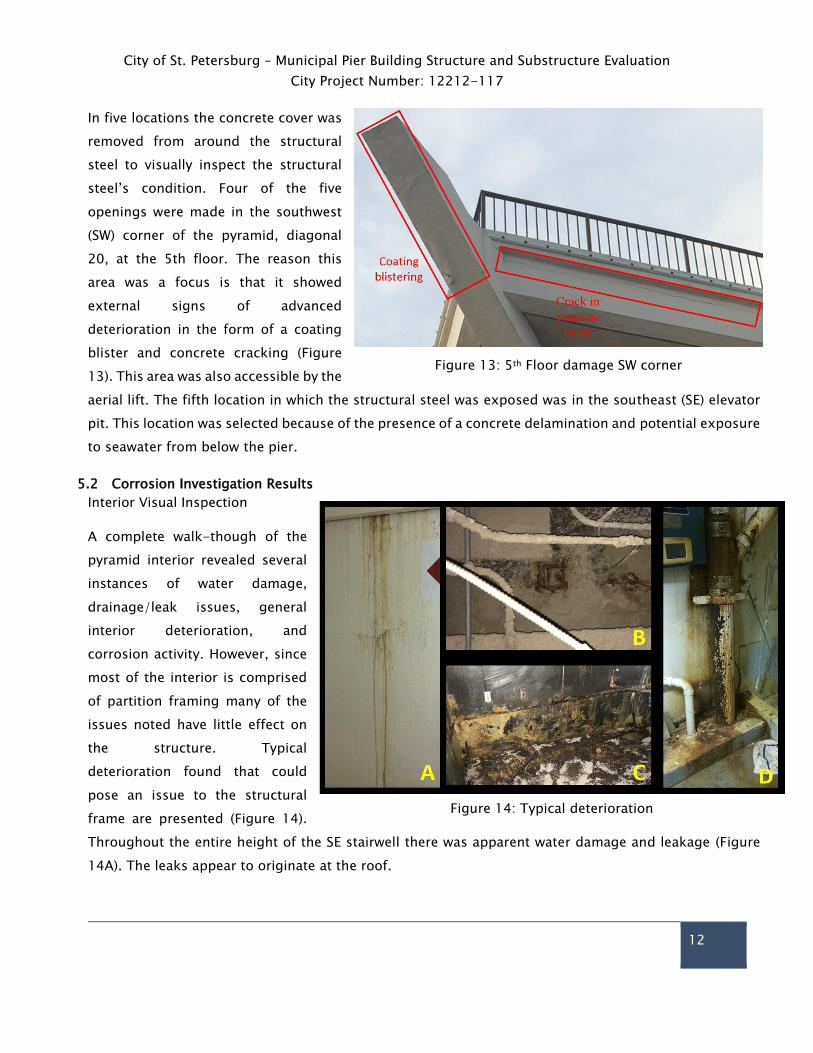
In five locations the concrete cover was
removed from around the structural
steel to visually inspect the structural
steel’s condition. Four of the five
openings were made in the southwest
(SW) corner of the pyramid, diagonal
20, at the 5th floor. The reason this
area was a focus is that it showed
external signs of advanced
deterioration in the form of a coating
blister and concrete cracking (Figure
13). This area was also accessible by the
aerial lift. The fifth location in which the structural steel was exposed was in the southeast (SE) elevator
pit. This location was selected because of the presence of a concrete delamination and potential exposure
to seawater from below the pier.
5.2 Corrosion Investigation Results
Interior Visual Inspection
A complete walk-though of the
pyramid interior revealed several
instances of water damage,
drainage/leak issues, general
interior deterioration, and
corrosion activity. However, since
most of the interior is comprised
of partition framing many of the
issues noted have little effect on
the structure. Typical
deterioration found that could
pose an issue to the structural
frame are presented (Figure 14).
Throughout the entire height of the SE stairwell there was apparent water damage and leakage (Figure
14A). The leaks appear to originate at the roof.
Figure 13: 5th Floor damage SW corner
Figure 14: Typical deterioration

City of St. Petersburg – Municipal Pier Building Structure and Substructure Evaluation
City Project Number: 12212-117
13
Most of the interior structure has a dropped ceiling. Tiles in random locations throughout the building
had been removed. This facilitated the visual inspection of a majority of the floor slab soffit. The floor
slabs throughout the building appeared in generally good condition except for areas similar to a location
on the bottom of the 4th floor (Figure 14-B). Corrosion of the reinforcement and concrete spalling were
observed at this location. Buckets and trays were below this damage to catch water. It appears this
deterioration is a result of a leak allowing water throughout this area.
There are several kitchens throughout the building and all were in a similar state (Figure 14C). Due to its
current condition, it is likely that significant amounts of moisture and other materials have reached the
slab and walls in areas like this, rendering deterioration likely in the structure around these kitchen areas.
The NE stairwell utility closets previously housed equipment for an aquarium attraction, which included
tanks, pumps, drains, and piping. The NE stairwell utility closets currently have large amounts of water
damage and corrosion staining (Figure 14D). This area is also at risk for chloride intrusion since the
aquarium housed saltwater tanks. As a result of the presence of moisture and chlorides, the NE stairwell
is an area at risk for corrosion activity. The northwest (NW) stairwell utility closets housed electrical
equipment and did not show signs of deterioration like the NE stairwell, due to reduced exposure to
moisture.
5.2.1 Elevator Pit Corrosion Inspection
The elevator pits in the NW, SW, and SE were inspected for corrosion related concrete deterioration as
the elevator pit above the W caisson was inaccessible. The power to the W elevator had been turned off
and the elevator was resting at the lowest level, which restricted access into the pit.
Delamination and cracking of the concrete were observed on the floor and walls of the elevator pits
(Figure 15). Figure 15A and Figure 15B provide an overview of the elevator pit layout. Figure 15A is the
SE elevator pit and Figure 15B is the SW elevator pit. The elevator pits contain mechanical equipment
making access more difficult.

City of St. Petersburg – Municipal Pier Building Structure and Substructure Evaluation
City Project Number: 12212-117
14
Cracking was observed in the floor of the NW elevator pit
(Figure 15C). The NW pit was the most deteriorated of
the three elevator pits inspected. The floor had large
amounts of cracking and the walls had large areas of
delaminated concrete.
The deterioration in the SW (Figure 15D and Figure 15E)
and SE elevator pits was similar. The walls had areas of
delamination that extended up the concrete wall to the
concrete masonry unit topping. A common area of
concrete delamination was along the corners of the
elevator pit. A large primary structural concrete encased
steel column is located at the corner of the pit.
5.2.2 Exterior Visual Corrosion Inspection
During the exterior visual inspection several areas of
deterioration were identified. Figure 16 and Figure 17
depict the type of damage that was observed. Due to
access restrictions, the damage observations are limited
to what could be seen from the roof of the first floor. The
limited proximity to the structural members restricted the
ability to provide an in-depth inspection.
Diagonals 33, 34, 35, and 36 all showed signs of
transverse cracking along the bottom flange, from the 4th
floor to 5th floor (Figure 16A). The cracking appears to
have been recoated at some point in the life of the
structure. Transverse cracking like this indicates damage
as a result of deflection or shrinkage as opposed to
corrosion activity. However, if the cracks were left exposed
to the exterior environment for a significant amount of
time it could allow for the ingress of chlorides and carbon
dioxide. This could lead to the initiation of corrosion
activity in these areas.
Figure 15: Elevator Pits
Figure 16: Exterior Damage

City of St. Petersburg – Municipal Pier Building Structure and Substructure Evaluation
City Project Number: 12212-117
15
A horizontal crack was identified along the exterior face of the north block out, located between diagonals
33 and 34 (Figure 16B). The interior of this block out contains a walk in refrigerator/freezer. The crack
could be the result of corrosion activity due to excess moisture resulting from the refrigerator unit. Areas
in the structure which contain large refrigerator/freezer units have the potential to supply the
surrounding structure with excess moisture. Moisture infiltration could lead to reinforced concrete
deterioration in these areas. Additionally, there is a walkway from the 3rd floor to the W elevator. The
bottom of this walkway shows signs of water damage (Figure 16C). Inspection from the interior of the 3rd
floor did not reveal any signs of water damage.
A common damage type that was
observed on the pyramid structure
was horizontal cracking in the
concrete encasement of beams
located at the 5th floor (Figure 16D).
This type of cracking was observed in
the SW, SE, and NW corners of the
structure. It extends from the corner
diagonals in the beams through
several column lines in each direction.
The crack is severe and provides a
pathway for chlorides and
carbonation to easily reach the
structural steel.
There was a large vertical crack in the SE corner column (Figure 17A). The crack has been sealed with the
exterior coating material. There appears to be no crack in the coating, indicating that the crack hasn’t
moved since the latest coating application. Depending on how long the crack had previously been
exposed to the environment there is a potential for corrosion activity of the structural steel in this area.
A spall, exposed reinforcement, and corrosion product were observed on diagonal 8 (Figure 17B). The
exposed steel is the steel welded wire fabric that is wrapped around structural steel in the diagonals.
This was the only instance on the exterior of the structure in which the reinforcement was exposed.
Deterioration of the 5th floor beams under the roof scuppers was observed in many locations. The
scuppers provide a pathway for water to drain off of the roof. However, when water travels through the
scuppers it runs directly over the 5th floor beam. Direct drainage over the beams supplies the concrete
Figure 17: Exterior Damage
City of St. Petersburg – Municipal Pier Building Structure and Substructure Evaluation
City Project Number: 12212-117
16
with a high level of moisture, oxygen, and possible chlorides. This creates a favorable environment for
corrosion activity. Corrosion staining, cracking, and blistering of the elastomeric coating was observed
in the scupper regions (Figure 17C).
Corrosion product, cracking, and blistering of the coating of the HVAC intake along the east face of the
pyramid is visible (Figure 17D). It appears that there is water damage around this intake. An external
pipe on the west face of the pyramid structure has an apparent leak as identified by significant corrosion
product around the fitting running down to the top of the 1st floor roof (Figure 17E). A common cause
for deterioration throughout the structure is a direct result of water leakage. The beam under this location
is being exposed to a large amount of moisture which could lead to deterioration.
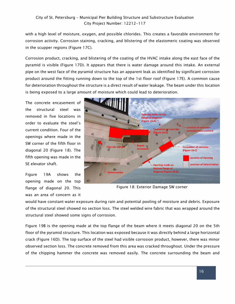
The concrete encasement of
the structural steel was
removed in five locations in
order to evaluate the steel’s
current condition. Four of the
openings where made in the
SW corner of the fifth floor in
diagonal 20 (Figure 18). The
fifth opening was made in the
SE elevator shaft.
Figure 19A shows the
opening made on the top
flange of diagonal 20. This
was an area of concern as it
would have constant water exposure during rain and potential pooling of moisture and debris. Exposure
of the structural steel showed no section loss. The steel welded wire fabric that was wrapped around the
structural steel showed some signs of corrosion.
Figure 19B is the opening made at the top flange of the beam where it meets diagonal 20 on the 5th
floor of the pyramid structure. This location was exposed because it was directly behind a large horizontal
crack (Figure 16D). The top surface of the steel had visible corrosion product, however, there was minor
observed section loss. The concrete removed from this area was cracked throughout. Under the pressure
of the chipping hammer the concrete was removed easily. The concrete surrounding the beam and
Figure 18: Exterior Damage SW corner

City of St. Petersburg – Municipal Pier Building Structure and Substructure Evaluation
City Project Number: 12212-117
17
column was of a whitish color, while the
concrete from the deck had a yellowish
tint to it. At this point in time the
difference between the two materials is
unknown.
Figure 19C was an opening made in the
corner of diagonal 20 along the bottom
flange and north web. The exposed steel
was in good condition and showed no
signs of deterioration. The steel welded
wire fabric that was wrapped around the
structural steel, however, did have
corrosion product and minor section
loss.
An opening was made along the bottom
flange of diagonal 20 (Figure 19D). This
location was selected because it was
directly underneath an observed coating
blister. Hammer sounding identified this
area as a potential delamination. The
exposed structural steel had no signs of
corrosion activity. The steel welded wire fabric that is wrapped around the structural steel did, however,
show signs of corrosion activity. There was corrosion product along the exposed steel wire.
The final opening was made in the SE elevator pit in the western wall (Figure 19E). The SE elevator pit was
selected because it is the elevator closest to the bay and the western wall was selected because hammer
sounding identified a delamination in this area. The exposed steel was in good condition and did not
show any signs of section loss.
The concrete removed in all the excavations except the beam/diagonal connection (Figure 16B) which
had a large crack, was in sound condition. The concrete didn’t crumble or spall off under the power of
the chipping hammer.
All of the openings created by the inspection team were patched by VCS using Sika 212 and BASF gel
patch in accordance with manufacturers’ recommendations. Sika 212 was used to repair the concrete
Figure 19: Exterior Damage SW corner

City of St. Petersburg – Municipal Pier Building Structure and Substructure Evaluation
City Project Number: 12212-117
18
that was removed to expose the steel at the connection between the 5th floor beam and the 20th
diagonal. Form-work was constructed around this opening and Sika 212 was placed to repair the
removed concrete. BASF gel patch was used to repair all of the powder sample locations and the
remainder of the steel exposure locations. The BASF gel patch allows for placement without the use of
form-work in vertical and overhead situations. The BASF gel patch was hand packed into the concrete
openings- if the opening was large the material was placed in several lifts conducted throughout the
day.
5.2.3 Corrosion Potential Measurements
Corrosion potential measurements were collected along the beam and diagonal 20 in the SW corner of
the 5th floor and along diagonal 0 in the NE corner at the 2nd floor. The potentials measured in these
two areas resulted in no indication of active corrosion. The corrosion potentials ranged from −50 mV up
to −155 mV. There were no locations of sharp potential drops and the magnitude of the measured
potential indicate that the structural steel is primarily in a passive condition. The measured potentials
also indicate that the exterior concrete is relatively dry, thus providing a highly resistant layer.
5.2.4 Chloride Sampling
Figure 20 provides the results of the chloride content analysis conducted on the concrete powder
samples. The complete tabular results can be found in Appendix B. The chloride concentration in all
samples were primarily at or below 100 ppm at a depth of 1 inch from the exterior surface. A chloride
content of approximately 350 ppm or above is considered to be the chloride threshold for corrosion
initiation in uncarbonated concrete. It is clear from these results that the chloride content at the structural
steel level is well below this threshold. Based on the results of the chloride analysis, the concrete is
providing adequate protection for the structural steel in regards to the diffusion of atmospheric chlorides.

City of St. Petersburg – Municipal Pier Building Structure and Substructure Evaluation
City Project Number: 12212-117
19
5.2.5 Carbonation Depth
During the excavation of the concrete to expose the structural steel, concrete samples were taken and
sprayed with phenolphthalein. Figure 21 shows the results of these tests; areas dyed purple are areas
with a pH greater than 9.0 and are thus not carbonated. In Figures 21 A, B, and C the carbonation front
doesn’t extend past ¼ in. However, in Figure 21D most of the face is carbonated. This is because this
face is along the large crack identified at the beam-diagonal connection in the SW corner of the 5th
floor (Figure 16D). The crack exposed the concrete to the atmosphere and rain allowing for the
penetration of carbon dioxide, and removal of the free alkali that is necessary to retain a high pH
environment. Areas of sound concrete show no significant carbonation penetration. A carbonation front
of ¼” after 40 years of exposure indicates that the exterior coating and concrete are adequately
protecting the structural steel.
0
50
100
150
200
250
300
350
400
0 0.2 0.4 0.6 0.8 1 1.2 1.4 1.6 1.8 2
Ch
lori
de
Co
nte
nt
(pp
m)
Average Depth (in)
Beam 8.5 Beam 20.5 Beam 31.5 a Beam 31.5 b Diagonal 0
Diagonal 10 Diagonal 20 Diagonal 25 Diagonal 29 Diagonal 30
Figure 20: Chloride Content Results

City of St. Petersburg – Municipal Pier Building Structure and Substructure Evaluation
City Project Number: 12212-117
20
5.2.6 Caisson Condition
During this field evaluation only the top of the caissons were inspected. The tops of three caissons were
accessible from the elevator pits, which sit on top of the caissons. However, review of previous inspection
results has provided insight into the current condition of the caissons. An underwater inspection done
by McLaren Engineering Group in February 2013 and a concrete petrographic analysis by Terracon
Consultants in August 2013 provides the current information regarding the caisson condition.
The underwater inspection conducted in February 2013 included a visual inspection of the caissons and
used an ultrasonic thickness gauge to measure the thickness of the steel sheet pile. The following bullets
highlight the important information gathered from the underwater inspection report;
The exterior of the sheet piles is in fair to poor condition.
The sheet pile thickness ranges from 0.315 in. to 0.045 in.
Figure 21: Carbonation Depth Results
City of St. Petersburg – Municipal Pier Building Structure and Substructure Evaluation
City Project Number: 12212-117
21
There are multiple scattered holes in the sheet-pile that extended into the concrete of the caisson,
these holes range in width from 2 in. to 9 in. and up to a depth of 10 in.
No scour was observed at the bottom of the caissons. The rip-rap that is supposed to be present
was not visible - it is suspected that it is covered by sediment.
Most of the previous dive inspection focused on evaluating the condition of the sheet pile. The sheet pile
is a stay-in-place form and does not provide significant structural support to the caissons or structure.
There are areas in which the sheet pile has holes allowing for saltwater to reach the concrete directly.
However, even in these areas the concrete provides 20 in. of cover for the caisson H-piles and at the
worst spall depth of 10 inches, there is still 10 inches of concrete cover.
As a part of the previous study, cores were collected from the caissons and tested in the laboratory. Two
cores were taken 2 ft. above the water line from each caisson, except at the W caisson in which only one
core was taken. The area 2 ft. above the water line is an aggressive environment due to the repeated
wetting and drying by saltwater. This wetting/drying effect allows for chloride to concentrate at the
surface and to penetrate into the concrete at a much quicker rate than if constantly dry or wet. This area
also has an increased level of oxygen, which facilitates corrosion.
The following provides an overview of the key findings from the concrete core laboratory testing;
The carbonation depth was minimal.
No visual or physical signs of alkali-silica reaction.
All of the compressive strengths measured were above 4000 psi
The maximum chloride concentration recorded at a depth of 6 in. was 160 ppm.
It is important to note that the McLaren report identified the caissons using a 1 through 5 numbering
system. VCS has used a cardinal direction coordinate system to identify the caissons. The conversion
between McLaren and VCS caisson identifications is presented in Table 3.
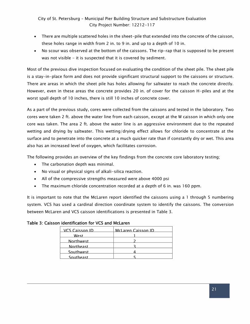
Table 3: Caisson identification for VCS and McLaren
VCS Caisson ID McLaren Caisson ID
West 1
Northwest 2
Northeast 3
Southwest 4
Southeast 5

City of St. Petersburg – Municipal Pier Building Structure and Substructure Evaluation
City Project Number: 12212-117
22
5.2.7 Summary of Corrosion Findings
The inverted pyramid structural frame is in overall good condition for a structure of its age but is in need
of maintenance repairs. Currently, roof leaks are allowing water to enter the interior and damage is
occurring as a result. Water is entering areas adjacent to roof scuppers and along cracks in the concrete
encasement surrounding the steel frame. These areas have isolated corrosion that can be mitigated.
Due to the large size of the structural steel members a small amount of corrosion product over the steel’s
large surface area is creating a large delamination. While the concrete is damaged the structural steel
damage has been observed as minor. These areas require repair. Delaying repairs will result in more
corrosion damage over time.
Any area of prolonged water exposure is an area of potential deterioration.
Interior of Structure
Several areas were identified with localized deterioration as a result of direct exposure to
moisture.
Areas of the structure which were previously kitchens, refrigerators, or freezers will require some
repairs to surrounding walls and slab.
The SE stairwell has damage due to an apparent roof leak. This area requires additional
investigation to determine the extent of deterioration.
There are isolated areas with localized corrosion and deterioration in the floor slabs and beams.
These areas can presently be considered minor repairs.
The NE stairwell is in need of additional evaluation as it was previously used to house saltwater
aquarium equipment.
The elevator pits have some limited concrete deterioration. However, the structural steel had
minimal section loss and is considered to be in good condition.
Exterior of Structure
The overall exterior of the structure is protected as a result of the concrete encasement and
surface coating of the structural steel. There are limited areas of concrete deterioration but the
underlying structural steel is in generally good condition based on the areas tested.
The exterior coating has provided a barrier to slow penetration of atmospheric chlorides and
carbon dioxide.
Diagonals 33, 34, 35, and 36 have potential damage as a result of observed transverse cracking
between floors 4 and 5.
City of St. Petersburg – Municipal Pier Building Structure and Substructure Evaluation
City Project Number: 12212-117
23
The horizontal cracking in the 5th floor beams at the corners of the structure represent the most
serious observed deterioration. The section loss to the beam in this area is minor but the concrete
damage is severe and should be addressed to preserve the structural steel.
The welded wire fabric around the structural steel has been observed in several cases to be
corroding adjacent to cracks and spalls.
Areas near the scuppers have observed areas of deterioration as a result of exposure to moisture.
The concrete surrounding the structural steel appears to be of generally good quality.
Caissons
While the H-piles in the caissons have not been directly investigated, the information provided in
previous inspections done by McLaren Engineering and Terracon leads VCS to believe that the H-
piles should be subject to limited corrosion.
Most of the observed sheet pile is intact which still provides a limited barrier for the concrete.
There are areas of damage in the sheet pile and concrete that could be addressed for additional
protection of the caissons.
Chloride penetration into the concrete, based on samples previously taken, is not sufficient to
raise immediate corrosion concerns for the structural H-piles.
The H-piles have a concrete cover of 20 inches, which provides a durable and cost effective
corrosion barrier. Some localized areas have voids noted that will reduce the effectiveness of the
barrier, so future evaluation in these areas is recommended.
Structural Conclusion
Based on the selective demolition and limited condition survey of the structure, the exterior steel
components of the building structure appear to have minimal amounts of corrosion present. The column
base plates and anchor bolts in the elevator shafts were observed to evidence only surficial corrosion.
The observed portions of the tops of the caissons also did not evidence moisture intrusion which would
have been indicative of an increased potential for corrosion of the embedded steel components. Of the
four areas exposed at the southwest top portion of the building structure, only one area evidenced
corrosion. Surficial corrosion was observed at the top flange of the beam and does not warrant structural
repairs. Corrosion of other steel components was observed at the underside of the southwest diagonal
steel beam and was limited to the welded wire fabric within the concrete encasement. Based on the
assumption that the limited condition survey results from the southwest corner of the building are
representative of the remaining structure, the existing structural components would not require
extensive repairs due to corrosion of the steel framing components. Repairs to some extent will likely be

City of St. Petersburg – Municipal Pier Building Structure and Substructure Evaluation
City Project Number: 12212-117
24
necessary to address unknown or hidden damage that could be exposed during construction. Such
damage often occurs as a result of long-term exposure to environmental conditions, necessary
maintenance, wear, and/or original construction deficiencies.
While the structure framing was found to not evidence significant corrosion, an analysis of code required
loading indicates that the current wind pressures that the structure will be required to withstand are
approximately 32%-121% greater, depending on which section of the building is being compared, than
the wind pressures the structure was originally designed to withstand. In order to determine if the
existing structure can meet the required wind loading, a detailed analysis of the structure would be
required. If the structure is found to not be able to meet current wind load requirements, then significant
structural modifications will be necessary to strengthen the connections, beams, and columns for the
steel structure. The cost of any necessary structural modifications could be determined after completion
of a wind analysis.
In addition to wind load related issues, a flood hazard analysis also indicates that the existing first floor
elevation is approximately 4’-8” (given the example conditions described above) lower than that required
by current code. The replacement first level would therefore be required to be elevated to meet current
code requirements thus resulting in a decreased ceiling height (from 12’-0” to 7’-4” given the example
conditions described above). The decreased ceiling height would likely be less than the minimum outlined
in the building code and would have a significant impact on the aesthetics of the structure. The elevated
first floor would also require the elevators and stair systems to be reconfigured to accommodate the
increased floor elevation. Replacement of original pier components below the first level and within the
footprint of the building would present significant access and coordination challenges.
Recommendations
If the existing building structure is found to be capable of meeting the required current design wind
pressures, or is strengthened to do so, and has the first level either increased in height or eliminated,
then our team recommends that a periodic and proactive maintenance plan would be necessary to extend
the building’s service life. The building structure is approximately 44 years old and if reused with a new
pier structure would be required to meet the new pier’s service life of approximately 75 years. The
inverted pyramid structure would therefore be expected to have a total service life of up to 119 years
which is greater than most structures constructed in an aggressively corrosive environment (e.g.
immediate proximity to salt water). If the structure is to be reused, the cost of ongoing maintenance
should be considered. Without addressing these ongoing maintenance items, the structure likely will not

City of St. Petersburg – Municipal Pier Building Structure and Substructure Evaluation
City Project Number: 12212-117
25
last another 75 years. The maintenance should include, at a minimum, the following to properly attempt
achieving this service life:
Implementation and maintenance of an active cathodic protection (CP) system to protect
vulnerable areas of the steel structure and piles.
Removal of deteriorated concrete and replacement with cementitious products (e.g. concrete,
repair mortars, etc.) containing corrosion inhibitors. Removal and replacement of deteriorated
concrete may be required on a 5-10 year cycle for areas exhibiting corrosion of welded wire fabric
within the concrete encasements.
Removal of the existing window assemblies and replacement with window assemblies meeting
current required design wind pressures and impact ratings. The replacement window assemblies
should have the perimeter sealants and glazing periodically removed (as necessary) and replaced
to mitigate moisture intrusion. Dependent upon which material is used (e.g. silicone, urethane,
hybrid, etc.) the recommended replacement cycle will be approximately 5-10 years.
Application of urethane membranes to exterior horizontal concrete surfaces. An exposed
unreinforced high traffic urethane membrane should be replaced on an approximate 5 year cycle.
A reinforced urethane membrane with low traffic rating should be replaced on an approximate 20
year cycle.
Application of a high quality acrylic paint to vertical exterior building components and beam
encasements. The paint should be reapplied on an approximate 5 year cycle.
Repair of localized areas of interior deterioration.
o Areas near the kitchens and refrigerators/freezers will most likely need rehabilitation.
Localized repair of damage to the interior beams and slab mostly located around areas of
excessive moisture.
Application of corrosion protection measures to interior structure.
o To insure the interior repair areas do not create future corrosion issues, corrosion
protection measures in the form of discrete alkali-activated zinc anodes are
recommended.
Redesign of roof drainage to prevent future deterioration.
Repair of Caissons.
o Removal of marine growth from sheet piles. Repair of the holes in the sheet pile. Removal
and replacement of deteriorated concrete in elevator shafts.
Protection of the sheet pile from further deterioration.
o Application of cathodic protection to sheet pile in the form of a bulk aluminum anodes
and a marine coating above the low water line.

City of St. Petersburg – Municipal Pier Building Structure and Substructure Evaluation
City Project Number: 12212-117
26
In-depth investigation of the caisson’s H-piles and pyramid’s structural steel.
o The current investigation was a preliminary assessment. However, to fully develop a
complete repair strategy, several more large openings in the concrete encasement must
be made to expose the structural steel in the caissons and pyramid.
Application of corrosion protection measures to caisson’s H-piles.
Application of cathodic protection in the form of an impressed current system is a possible repair
strategy. However, a corrosion investigation of the H-piles is recommended to determine if
cathodic protection is necessary.
A cost estimate for carrying out necessary structural modifications/strengthening can be
completed based on the results of an in-depth wind loading analysis of the existing structure.
An analysis of construction feasibility considerations is necessary for the reconstruction of the
first floor elevation.
Neither the survey nor this report is intended to cover hidden defects, mechanical, electrical, or
architectural features, nor environmental concerns. The information contained in this report may be
updated at a later date if deemed necessary due to modified site conditions or the availability of
new/additional information.
City of St. Petersburg – Municipal Pier Building Structure and Substructure Evaluation
City Project Number: 12212-117
27
Appendix A- FIRM Map

City of St. Petersburg – Municipal Pier Building Structure and Substructure Evaluation
City Project Number: 12212-117
28

City of St. Petersburg – Municipal Pier Building Structure and Substructure Evaluation
City Project Number: 12212-117
29
Appendix B – Chloride Test Results

City of St. Petersburg – Municipal Pier Building Structure and Substructure Evaluation
City Project Number: 12212-117
30

City of St. Petersburg – Municipal Pier Building Structure and Substructure Evaluation
City Project Number: 12212-117
31