Final Report - EUROPA · Final Report Project No: 214832 ... MEMS or medical devices. ... The most...
49
EUROPEAN COMMISSION RESEARCH AND INNOVATION DG Final Report Project No: 214832 Project Acronym: SUPERLION Project Full Name: Superior Energy and Power Density Li-Ion Microbatteries Final Report Period covered: from 01/09/2008 to 31/08/2011 Date of preparation: 23/05/2011 Start date of project: 01/09/2008 Date of submission (SESAM): Project coordinator name: Prof. Josh Thomas Project coordinator organisation name: UPPSALA UNIVERSITET
Transcript of Final Report - EUROPA · Final Report Project No: 214832 ... MEMS or medical devices. ... The most...
EUROPEAN COMMISSIONRESEARCH AND INNOVATION DG Final Report
Project No: 214832
Project Acronym: SUPERLION
Project Full Name: Superior Energy and Power Density Li-IonMicrobatteries
Final Report
Period covered: from 01/09/2008 to 31/08/2011 Date of preparation: 23/05/2011
Start date of project: 01/09/2008 Date of submission (SESAM):
Project coordinator name:Prof. Josh Thomas
Project coordinator organisation name:UPPSALA UNIVERSITET
Final Report
PROJECT FINAL REPORTGrant Agreement number: 214832
Project acronym: SUPERLION
Project title: Superior Energy and Power Density Li-IonMicrobatteries
Funding Scheme: FP7-CP-FP
Project starting date: 01/09/2008
Project end date: 31/08/2011
Name of the scientific representative of theproject's coordinator and organisation:
Prof. Josh Thomas UPPSALA UNIVERSITET
Tel: +46-18-4713763
Fax: +46-18-513548
E-mail: [email protected]
Project website address: superlion.eu
Project No.: 214832Period number: 1stRef: intermediateReport994456
Page - 2 of 49
Final Report
Please note that the contents of the Final Report can be found in the attachment.
4.1 Final publishable summary reportExecutive Summary
SUPERLION passed through an “academic” phase (months 1-18), dominated by basic researchefforts by the University partners, prior to the participation of industrial partners (months 19-36),aimed at providing “proof-of-concept” through the fabrication of one or more functioningthree-dimensional 3D-MBs.• 3D-MB design specifications: Area Gain (A.G.) factor 30; benchmark “footprint” capacity: 30-50µAh/mm2 - delivering an energy density of 100-200 µWh/mm2 for a stack-thickness of 500-1000µm.• FEA modelling exposed significant non-uniformities in current distributions within working cells,which were strongly dependent both on design architecture and choice of component materials.• Deposition of negative and positive electrode materials as conformal films on nano-structuredcurrent collectors gave many new advances: LiFePO4 onto the surface of reticulated vitreous carbon;a new “copper-trench” current-collector architecture; thin-film polymer electrolytes self-assembledas surfactant oligomers on LiFePO4 particles.• Negative Sb and Cu2Sb electrodes have been electrodeposited successfully onto 15µm Cumicro-trenches. Likewise, LiFePO4 and LiCoO2 positive electrodes have been deposited ontocolumnar and needle-like Al current-collectors to give good capacity retention at 1C rate. CuScathodes (with a perforated Si substrate) cycled more than 400 times with ~0.1%/cycle capacity-lossin the range 0.1-2.0 mA/cm2 with pulse-power capability ~ 160 mW/cm2. CorrespondingLiFePO4-cathode cells gave a capacity of 80 µAh/cm2 with an average potential of 3.4 V after 20cycles, and a pulse-power peak of ~ 175 mW/cm2 for a 1s discharge pulse-step. MnO2 half-cellsshowed capacities (in mAh/cm2) up to 200 times greater than for comparable 2D planar electrodes.Charge/discharge behaviour for LiFePO4 shows a significant increase in capacity in going fromusing 5 (130 µAh/cm2) to 10 (870 µAh/cm2) wt.% inks.• “Trench-type” 3D-MB cells have been developed by dropwise insertion of LiCO2 into thetrenches, and by attachment of the composite cathode to the anode/polymer structure through theapplication of gentle pressure. LiFePO4-based 3D-MB half-cells have been assembled successfullywith aperiodic architecture to give a capacity of 1.5mAh/cm2. Complete <TiO2/solid polymerelectrolyte/LiFePO4> 3D-MB whole-cells with aperiodic architecture gave a stable OCV, whileconcentric Li/LiFePO4 half-cells gave a capacity of 1.5-2.5 mAh/cm2 for >100 cycles and>200mW/cm2 pulse-power capability.
Proof-of-concept activities by the industrial partners focussed on three test-cell types: aLiFePO4-based flexible flat cell; MC 614 and V500 coin-cells. To summarize the findings of thiswork: although these showed promising characteristics in terms of size and energy-density, theirelectrochemical performance must be further improved for use as realistic power sources in futureMEMS or medical devices. Improvements must be made primarily in the materials processingphase; battery production processes must also be optimized, since the intrinsic performance ofsingle-cell components has been well demonstrated on a laboratory scale. Rate capability and pulseperformance must also be improved. Internal resistance should also be further reduced. Highersystem capacities will also be necessary to increase their capacity range from µAh to mAh. A highervolumetric energy density will also be required in some applications, especially when highercapacities are needed as the cells get larger.
The feasibility of incorporating 3D-MB concepts into conventional Li-ion battery production wasseen an extra bonus of the project. The most interesting candidate was adjudged on the basis of itssuperior mechanical properties to be the “aperiodic sponge” architecture. However, electrochemicalstability limitation of the Ni-foams is still seen as a problem. Financial aspects must also be carefullyevaluated.
By the end of the project, proof-of-concept for 3D-MBs has been achieved at a design level, butno pilot-line production of 3D-structured electrode materials or cells yet exists.
Project No.: 214832Period number: 1stRef: intermediateReport994456
Page - 3 of 49
Summary description of project context and objectives
Access to on-board micro-battery power is fast becoming an essential requirement in many oftoday’s emerging technologies. It is clear to all that down-scaling in the micro-electronics industryhas far outpaced advances made in small-scale electrical power supplies. Indeed, the continuedabsence of efficient on-board power is already becoming a severe hinder to further advances in manycritical areas; typically, in many MEMS-type devices, not least biomedical in vivo micro-machines.Down-scaling the battery power source clearly presents a serious challenge to Science, but the adventof nano-materials and nano-structures now places new resources at our disposal to facilitate a freshattack on the problem. SUPERLION make this attack.
More specifically, recent miniaturisation of electrical, mechanical and optical systems has led to avariety of devices with a total volume of little more than 10 mm3. Though many have never evenheard of these, there is an emerging range of micro-scale devices (called Micro-Electro-MechanicalSystems – MEMS) which are destined to change our lives completely. These devices include smartmicro-sensor arrays for detection of hazardous materials, anti-terrorism microchip sensors,self-powered unmanned air micro-vehicles, fully integrated RF identification cards, non-volatile PCmemory backup, not to mention the exciting new area of biomedical in vivo micro-machines, such aspacemakers, defibrillators, neural stimulators, drug delivery systems, micro-imaging capsules, etc.The USA demand for cardiac and orthopaedic implants, for example, is increasing at ca. 11%annually.
As intimated above, the major obstacle today to the widespread development of thesemicro-devices is the lack of a suitable autonomous battery power source. The realization that thepower requirements of such micro-systems cannot be met by existing lithium or lithium-ionsolid-state thin-film batteries in flat 2D-configuration has led to the search for a true3D-microbattery(3D-MB), where the critical bottleneck is the shortage of cheap, light and powerfulmicro-/nano-fabrication materials. The fundamental problem with planar 2D thin-film batteries istheir limited active electrode surface. Moving into the 3rd dimension invokes the simple principle ofgeometrical Area Gain (A.G.), resulting in electrode volume gain with associated increase in batterycapacity. An obvious approach to achieve significant A.G. (by a factor of up to 25-40) is to replace acontinuous by a perforated substrate (with high aspect-ratio channels), thereby better utilizing thedead volume of the substrate.
While focussing on this central goal of achieving greatly improved MB performance through theuse of new nano-materials and -architectures in a 3D-MB concept, it is tempting to raise the questionas to what extent these same (or related) techniques can also be used to improve the performance ofthe conventional normal-scale Li-ion battery. Can we, indeed, move from today’s methodologiesinvolving an assembly of five separate cell components to a fabrication technique involving onesingle chemically-formed battery laminate, comprising interpenetrating (“nano-architectured”)substrates, anode and cathodes elements separated by an electrolyte? Can our 3D-MB related workalso serve as a stimulus to a paradigm shift in the production of conventional rechargeable Li-ionbatteries, which could meet current demands for better large-scale battery performance in, typically,EV/HEV applications?
The MAIN PROJECT OBJECTIVES of SUPERLION are therefore:• Synthesis and fabrication of novel nano-architectured battery materials and components for use in3D-MB concepts.• Implementation of these in fully integrated thin-film 3D-microbatteries (3D-MBs) with energy,capacity (and power) per footprint area at least an order of magnitude greater than that of planar (2D)thin-film battery.• Implementation of at least some of these 3D-MB concepts in conventional normal-scale Li-ionbattery fabrication.• “Proof-of-concept” by showing that some 3D-MB concept from the project can power an electronicand/or a medical MEMS device.
The project, in this way, establishes a platform of 3D nano-architectures and micro-/nano-fabricationtechniques, and the associated enabling Science for a new generation of microbatteries.
Description of main S & T results/foregrounds
1. Modelling the 3D Microbattery1.1 Static modelling of various 3D microbattery architectures
Project No.: 214832Period number: 1stRef: intermediateReport994456
Page - 4 of 49

The main focus of the static simulation of the 3D Li-ion battery was to derive the capacities andenergy limits for prospective 3D Micro-Batteries (MBs) of various designs. If 3D-MB design isbased on conformal layer deposition, then the capacity and energy gain is a function of thegeometrical Area Gain (AG). However, several prospective MB designs are essentiallythree-dimensional; their properties cannot therefore be calculated on the basis of AG alone. A specialanalysis must be made for such MB designs; namely, the capacity and energy of the 3D-MB iscalculated on the basis of geometrical parameters and the density/specific capacity of the materials.This approach and details of the derivations involved can be found in the “Static Modelling” reportplaced on the SUPERLION website. The most relevant MB designs considered were: 3Dinterdigitated (row and interlaced), 3D continuous anode, and 3D continuous cathode.
The following questions relevant to 3D-MB design can be solved with the help of the deliveredMatlab procedures: (1) What is the minimal thickness of the 3D-MB necessary to reach the targetedvalues of 300 µAh/mm2 in capacity and 900 µWh/mm2 in energy density? (2) What cathode andanode column radii are needed to reach optimal volume utilization? Precise answers to thesequestions depend on the design parameters and the electrode materials selected. Interlaced and rowdesigns are shown to be identical in capacity and energy per footprint area; and device thickness of1.3-1.5 mm is sufficient to reach the targeted capacity and energy densities per footprint area.
The second important 3D-MB design involves continuous (tube formed) anodes and cathodes.Continuous cathode and especially continuous anode geometries provide higher volume utilizationthan a 3D interdigitated design. Smaller device thickness (0.8-1.0 mm) can thus be achieved.1.2 Dynamic modelling of 3D microbatteries
Dynamic modelling is essential in studying discharge processes in a 3D-MB, since it providesinformation on current densities within the battery, and hence on material utilization. Current movesdifferently through the battery depending on the 3D-MB architecture. In order to simulate theelectrochemistry under operation of a complete 3D-battery cell, such a system needs to be modelledin all three dimensions. This has been accomplished using Finite Element Analysis (FEA) throughthe COMSOL Multiphysics program package. The input parameters to the program are here: thespecific 3D-MB geometry, the electrochemical description, and material-specific parameters, such asconductivity.
The complete battery – involving electrochemical processes in both the electrodes and theelectrolyte - has been modelled for both interdigitated “trench” and pillar designs. The FEAsimulations of 3D-cells of graphite, 1 M LiPF6 in EC/DEC and LiCoO2 in the trench-modelgeometry were performed using concentrated solution theory, Maxwell-Stefan diffusion andButler-Volmer kinetics. In addition to modelling the overall discharge characteristics, the model alsoexposed large non-uniformities arising in the current distribution. These were seen to be dependentboth on architecture – trench depth, trench separation, plate shape – and on choice of material. Sincenon-uniform activity at the electrode/electrolyte interface results in a non-uniform utilization of theactive material, these factors have a substantial influence on the charge/discharge profile of thebatteries. A non-optimal battery design thus results in a non-optimal current distribution andelectrode activity, and hence to an under-utilization of the active material. At the beginning of adischarge cycle, delithiation and lithiation of the electrodes starts directly from the plate tips in thetrench-cell, leading to a fast depletion and accumulation of Li ions in these regions of the electrodes.This is due to the inhomogeneous current density distribution which is, in turn, caused by theelectrode tip being considerably smaller than the corresponding surface of the opposite plate; thisresults in a concentration of current density at the tip – a direct effect of the interdigitated design. Thehigher local reaction rates at the plate tips will thus limit the current through the battery; the currenthas to find a different route through the cell, which brings the electrochemical processes to apremature end - at < 70% state-of-charge (SOC). In addition to this effect, it is anticipated thatinhomogeneous expansion and contraction of the electrode material can result in cracking anddisconnection to the electrodes, leading to poor capacity retention on cycling.2. Electrode and electrolyte deposition processes2.1 Current collectors
The key objective here is to deposit nanostructured current-collectors, and develop conformal andspace-filling methods for subsequent deposition of the electrode materials; alternatively, to fabricateporous solid electrolyte containers as templates for subsequent deposition of both active electrodelayers.2.1.1 Fabrication of Cu and Ni nanorod arrays
Arrays of free standing copper nanorods were fabricated directly on commercial copper disksubstrates by cathodic electrodeposition using a simple process developed earlier. Cu nanorods are
Project No.: 214832Period number: 1stRef: intermediateReport994456
Page - 5 of 49

grown from an electrolytic bath consisting of CuSO4 •5H2O 100 g L#1, (NH4)2SO4 20 g L#1 anddiethyl-tri-amine 80mLL#1, inside the pores of an alumina membrane placed on top of the Cusubstrate. Before electrodeposition, the Cu substrate was mechanically polished. After being rinsedwith deionized water and ultrasonically cleaned in ethanol, the copper cathode was assembled infront of a copper anode, with the cellulose paper separator between the electrodes. The resultingtwo-electrode stack was kept under a constant pressure by using two stainless-steel clamps during thedeposition process. Electrochemical Cu deposition was achieved using a pulsed cathodic currenttechnique, with a two-step profile. The pulsed electrodeposition technique promotes grain nucleationand avoids diffusion limitations and is preferred over the constant current technique. Afterdeposition, the two-electrode stack is removed from the solution under current, and the cell isdismantled. The cathode is soaked in hot alkaline solution (pH=14, 80 oC) to remove the AAOmembrane, then in an acidic copper sulphate bath to dissolve the surface copper oxide. Currentcollectors are then stored into a glove box under a 6 atm. argon atmosphere preventing them fromfurther oxidation. Uniform, defect-free and self-standing nanorod arrays are obtained which aredirectly attached to the underlying substrate. The length of the arrays could be varied with depositiontime. With longer deposition times, the nanorod arrays tend to form bundles; judicious use of thesecould result in novel micro current-collectors.2.1.2 Fabrication of Al nanorod arrays
Growth of Al nanorod current collectors has been achieved by direct electrodeposition of Alnanorods onto a planar aluminium substrate using porous alumina membranes from Ionic Liquids(ILs). Arrays of Al nano-rods (~200 nm diameter, ~5 µm high) have been grown on Al substratesusing ([EmIm]Cl)/aluminium chloride (AlCl3) (1:2 ratio) as the deposition electrolyte. The Lewisacid ionic liquid was prepared by slow addition of AlCl3 in [EMIm]Cl in an argon filled glove-box.The two compounds are both solid at room temperature and when mixed form a liquid, through ahighly exothermic reaction. Al nanorods were directly synthesised, using the pulsed conditions.Free-standing nano-arrays of aluminium rods were obtained after dissolution of the alumina templatein an aqueous solution of CrO3 (1.8 wt.%) and H3PO4 (6 wt.%).
Electrochemical cleaning of the surface of Al substrate with several potential scans by cyclicvoltammetry prior to Al electrodeposition has been shown to be an effective step for achieving betteradherence of the Al deposit on the substrate. This procedure reduces the thick Al2O3 layer present atthe substrate surface and results in better adherence of Al nano-rod deposits. It has been possible tofurther improve the adherence of Al nanorod deposit, resulting in much better homogeneous arraysof nanorods, by slightly modifying the growth parameters, especially the pulsed potential steps. Thegoal was to increase the nucleation on the substrate and to avoid any diffusion limitation generallyoccurred during electrodeposition in such nanochannels.2.1.3 Template–free electrodeposition of structured Al current collectors
Aluminium electro-deposits were grown on aluminium substrates from ionic-liquid electrolyticbaths using pulse currents. The deposits had a mole-hill type morphology which was found to adherenicely to the substrate. Differences were seen in deposition characteristics; typically in terms ofparticle-size and distance between particles.
Another common technique to deposit aluminium is the potentiostatic deposition method.Literature has often reported it as performed on several substrates and, each time, dense aluminiumlayers were obtained. A 2h deposition time was used in the [EMIm]TFSI/AlCl3 medium for variousvalues of the imposed potential. It was found that low voltages allow dense layers as expectedalthough increasing the voltage shows another aspect. Thicker aluminium layers were anticipatedbut, instead, the substrate was found not to be totally covered. This is explained by a partialdecomposition of the electrochemical bath occurring at the same time. The partial decompositionseems to have a beneficial effect on the structuration of the aluminium deposits.
Literature reported that cetyltrimethylammonium bromide (CTAB) allowed a columnar growth ofZnO during hydrothermal and electrochemical syntheses. Coupling this additive with a high voltagecould allow a good structure on our aluminium deposits. Experiment could confirm that the additivehad no effect on the deposits obtained in [EMIm]TFSI/AlCl3/CTAB for -0.2, -0.5 and -0.7 V vs.AlIII/Al. A columnar aluminium deposit was first obtained without the help of any template at -1.0V vs. AlIII/Al, with 0.5% mol CTAB in the electrochemical bath. Different textured aluminiumcurrent collectors were obtained using reduction processes in different deposition techniques. It wastempting to obtain a structure via the opposite route, i.e., by oxidation of an aluminium substrate.Different attempts were made; the most efficient was also the simplest: cyclovoltammetric oxidation.Different parameters had to be optimized like choice of the bath ([EMIm]TSFI/AlCl3), potentialrange (- 0.7 to 4 V vs. AlIII/Al), scan rate (100 mV s-1) and number of scans (100 and 1000). Each
Project No.: 214832Period number: 1stRef: intermediateReport994456
Page - 6 of 49
of these parameters was important to obtain a good oxidation of the substrate.2.1.4 Silicon microchannels made by lithography
Philips Research produce perforated Si wafers: 6-inch in diameter, 700 #m thick, N-doped and hasa conductivity of about 0.1 S cm-1. The DRIE technique was employed to etch the holes in thewafer. The aspect ratio achieved was ca. 20:3. Cross-sectional SEM images show the holes to be 60#m in diameter and with 400 #m penetration depth, with a ca. 10% broadening of the channel andnarrowing of the inter-channel space, respectively. This is not critical, because the design of maskconsiders possible widening of the micro-channels during the etching process. The roughness of theinternal surface is relatively low and is not expected to be detrimental for the deposition ofsuccessive battery layers.2.1.5 Fabrication of high aspect-ratio perforated and interlaced Si substrates
A mask design comprising 42 chips of 11.74 mm x11.74 mm with a perforated pattern of 7x7mm2 has been developed. The (round) chips have microchannels with a 50 µm diameter and 30 µmwalls. The aspect ratio of the 350 µm-thick substrate is 7 and the geometrical Area Gain (A.G.) factoris 9. The substrates were prepared by means of an inductively coupled plasma dry-etching technique(DRIE). Operation parameters such as flow rate, SF6 gas pressure, duration of etching-passivationsteps and RF-power-coil power were adjusted to obtain optimal conditions for the microfabricationof the desired microstructures. A morphing procedure was applied based on controlling the durationof the etching step. The final etching process consisted of varying the length of the etching step in500 deposition/etching cycles from 6 to 10 s. This suppressed the narrowing of the channels andreduced the roughness of the inner surface of the micro-containers formed. The mask design for theinterlaced silicon substrates has also been developed. The pattern of interlaced micro-container arrayswas prepared by double-side DRIE.2.1.6 Conformal coating of the perforated Si substrate
After the DRIE perforation, the silicon wafers showed a significant difference between the surfacemorphology inside a microchannel and that of a flat area. Before carrying out electroless nickel orgold deposition, perforated samples were cleaned either in acetone and then in ethanol, or incyclohexane followed by immersion in a solution of chromo-sulfuric acid. Modification of ametal-assisted etching method has been made to facilitate an appropriate roughness level of the Si togive strong adhesion to the current-collector. Two electrolytes, sulfate and sulfamate, were tested forthe electroless deposition of thin-film nickel on the three-dimensional perforated silicon. Thedeposits were characterized in terms of their structure, morphology, crystallization behaviour, andcomposition. It was found that a sulfamate-based electrolyte with double complexing/bufferingagents enables the deposition of a nickel layer with a homogeneous morphology and composition at acontrollable reduction rate. The coating is composed of about 1.5 nm-size crystallites and contains12-14% phosphorous.2.2 Electrodes2.2.1 Negative electrodes2.2.1.1 Electrophoretic deposition of SnO2 nanoparticles on Cu nanorods
Electrophoretic deposition (EPD) technique has been used for the conformal deposition of SnO2nanoparticles onto Cu nanorod current collectors. EPD is a versatile technique that allows depositionof nanomaterials with controlled size and crystallinity. Commercial SnO2 nanoparticles were used toprepare the dispersion for EPD in isopropanol. Polyethylene imide (PEI) was added as a stericstabilizer, to improve the stability of the suspension. As SnO2 particles showed a slight negative zetapotential in this media, a mixture of I2/acetone was added to the colloidal suspension to generateprotons, thereby switching the zeta potential from negative to positive values. The composition ofour ELD bath was SnO2 nanoparticles (0.5 g.L-1), PEI (0.05 g.L-1), I2 in acetone (a few droplets ofa 1 g.L-1 solution) in isopropanol. The mixture was immediately used after sonicating for 25 min.Electrophoretic deposition of SnO2 nanoparticles onto Cu nanorods have been carried out in ahomemade set up, with a stainless steel anode and Cu nanorod current collector as the cathode.Several parameters including solvents, concentration, applied field and time of deposition have beenvaried to obtain optimum deposition onto the Cu nanorod current collectors. A controlled field of 100V/cm was applied between the electrodes. Some of the interspaces between the nanorods areobserved to be filled with SnO2 nanoparticles. EPD deposition of SnO2 thin film has also beencarried out on planar Cu substrates in order to compare the performance characteristics of 2D and 3Delectrodes.2.2.1.2 Electrolytic Sb for nanostructured Cu2Sb anodes
The electrodeposition technique has been chosen to prepare nanostructured Cu2Sb active materialfor 3D MBs, since Sb will be alloyed with Cu from Cu nanorod current collector. Conformal
Project No.: 214832Period number: 1stRef: intermediateReport994456
Page - 7 of 49

deposition of antimony (Sb) onto Cu nanorods is achieved, and the aim was thus to prepare Cu2Sb asactive electrode material by alloying of the Sb with the copper current collector to prepare a 3Dnanostructured negative electrode.Antimony was deposited from an acidic solution of Sb-tartrate salts. The electrodeposition solutionwas based on a mixture of Sb and sodium tartrate, with the Sb concentration fixed to 0.15 M and thetartrate concentration set to 0.45 M. The pH of the solution was decreased to 1 by addition ofsulphuric acid. The reduction of Sb(III) to Sb0 can then be written as:
[Sb2(C4H4O6)2]2+ + 6e- # 2Sb0 + 2C4H4O62+The Sb reduction potential in this solution was evaluated for reduction at a planar Cu subtrate andthen reduction on a Sb layer previsouly deposited on a Cu substrate. A Pt disc was used as counterelectrode and the reference electrode was a saturated calomel electrode. To promote the diffusion ofthe electroactive species within the 3D structure and thus to obtain a uniform coverage of thecomplex 3D surface of the Cu nanorod current collectors, the electrodeposition was performed usingpulsed-current steps rather than a simple galvanostatic technique. 1st step: a constant current (idep)was applied for few ms (tdep) to favour nucleation. The electrodeposition parameters were varied toobtain optimum conditions. Homogeneous and conformal Sb deposits were obtained under theoptimized conditions: a deposition current fixed to -1 mA.cm-2 was held for 10 or 50 ms and wasfollowed by a rest step (0mA) of 50ms to allow diffusion of the Sb (III) complexes to the Cu 3Dsurface. When the deposition time and rest time were the same, larger Sb particles were obtainedbetween the nanorods. The Sb deposit appears smoother when the deposition step was decreasedfrom 50ms to 10ms. Both deposits can be suitable as 3D electrodes as they appear to cover the 3Dnanorod current collector homogeneously.2.2.2 Positive electrodes2.2.2.1 Ni/Al nanorod-supported LiCoO2 cathodes
One of the most common classes of cathode active materials that are being researched andcommercially used in lithium ion batteries are the lithiated transition metal oxides such as LiCoO2,LiNiO2, LiMn2O4, and the doped counterparts. Improved charge-discharge performance has beendemonstrated in the literature by decreasing the average grain size of these oxide materials, as shorterdiffusion length results in faster kinetics. With these practical implications, we have chosennanostructured LiCoO2 as the active material to design positive electrodes for 3D Microbatteries. Toaddress the objective of this work package, conformal deposition of positive electrode material ontonanostructured current collectors has been attempted.
Arrays of Ni and Al nanorods directly grown on the respective base substrates have been used aspositive current collectors for the conformal deposition of nanostructured LiCoO2. NanostructuredLiCoO2 was synthesized by thermal decomposition of sol-gel precursors spray-coated onto therespective nanorod current collectors. As a first step to establish the conformal deposition process, Ninanorod arrays have been used as positive current collectors.
The sol was prepared by dissolving stoichiometric amounts of nitrate salts (Li:Co = 1:1 molarratio) in de-ionized water and mixing well with citric acid and ethylene glycol (1:4 molar ratio) andthen evaporating at 80 deg.C for 5 h to form a transparent sol. Metal nitrates act as the cationsources, while citric acid and ethylene glycol serve as the monomers for forming the polymericmatrix. The sol was spray-coated onto the Ni nanorod arrays to cover the surface uniformly; theexcess sol on the membrane surface was wiped off, followed by drying in air for 60 deg, C for 1 h.The substrate surface was carefully wiped again to remove the salts crystallized on the surface andheated at 650 #C for 8 h in air atmosphere. The entire process was repeated 3-5 times for eachsample, resulting in the formation of a thick conformal coating of nano-structured LiCoO2 onto theNi nanorod arrays. The same procedure was followed for Al nanorod arrays to obtain Al-nanorodsupported LiCoO2 deposits. Uniform and conformal deposition of active material has been achievedon both Ni and Al nanorod arrays as seen in respective SEM images.2.2.2.2 CuSx deposition on silicon
Thin-film nanosize-particle copper sulfide cathodes have been electrodeposited on planar and 3Dsubstrates. The morphology and composition of the cathodes has been controlled by varying theoperating parameters, such as current density, pH, and temperature, of an electrolyte. The addition ofa polymer to the electrolyte bath enables the formation of sulfur-rich thick porous layers. This is notpossible without the additive, which serves to decrease the internal stresses in the bulk of the deposit.XPS tests showed that the CuSx cathode material obtained from the modified electrolyte is enrichedin high-sulfur-content compounds (65.6% w/w). However sulfur-deficient chalcocite (36.9% w/w) isthe dominating component of the high-deposition-rate samples. These samples, in addition, have themost oxidized surface (25.7% w/w CuSOx, x>1). Increasing the deposition time restores the original
Project No.: 214832Period number: 1stRef: intermediateReport994456
Page - 8 of 49

covellite content of the films and decreases surface oxidation (8.2% w/w CuSOx). TOFSIMS testson CuS cathodes, showed that the lateral distribution of sulfur and oxygen-containing coppercompounds is more homogeneous in modified samples compared to pristine.2.2.2.3 Electrochemically-assisted synthesis of LiFePO4 in ionic liquids
The use of ionic liquids is most appealing for electrochemical deposition at temperatures above100°C, and over a wider potential range than 1.2V. Electrochemically-assisted synthesis of LiFePO4has thus been made in two different ionic liquid media: [EMIm]TFSI and [EMIm]Tf. The process,developed using anhydrous soluble FeCl3 and insoluble Li3PO4 as precursors, involved two steps:(i) the potentiostatic electrochemical reduction of Fe(III) on Pt electrode, and (ii) the chemicalreaction between Fe(II) and Li3PO4 according to the following reactions:
Fe(III) + e- # Fe(II) and Fe(II) + Li3PO4(s) # LiFePO4(s) + 2Li+The conditions for electrochemically-assisted synthesis of LiFePO4 were optimized by studying
the effects of reduction potential, reaction time, molar ratio of two precursors and temperature. Thepurity of the synthesized solid had been followed by comparing the relative intensity of the mostintense XRD pattern lines of Li3PO4 and LiFePO4. The molar ratio and the temperature had a hugeeffect on the purity of the final product. Nearly pure LiFePO4 was obtained at 275°C, afterelectrochemical reduction of Fe(III) at -0.3V (vs. AgCl/Ag) for 5 h, from the electrochemical bathcontaining Fe(III) and Li3PO4(s) with a molar ratio of 2/1.
The feasibility of synthesizing LiFePO4 in ionic liquid medium via a novelelectrochemically-assisted chemical method has been demonstrated despite a limited chemicalcontribution, indicating that the ionic liquid acts as reducing agent of Fe(III). This is most likely dueto its decomposition at 275°C, which is on the verge of its thermal stability limit. To bypass thisissue, a more stable ionic liquid 1-ethyl-3-methylimidazolium trifluoromethanesulfonate ([EMIm]Tf)was used as reaction medium. Almost pure LiFePO4 has been prepared in [EMIm]Tf mediacontaining 0.1M FeCl3 and solid Li3PO4 with a molar ratio Fe(III)/Li3PO4 of 2:1, via conductingchronoamperometry at E=-0.3V(vs. AgCl/Ag) for 5 hours at 220°C. Much higher reactivity ofLi3PO4 in [EMIm]Tf leads to a lower reaction temperature, thus preserving the thermal-chemicalstability of the ionic liquid solvent. Unreacted Li3PO4 and Fe3(PO4)2 were identified as impurities.Besides, higher temperatures and longer reaction times favour the formation of Fe3(PO4)2. So,within this ionic liquid medium we experienced a competition between two reactions leading,depending upon the temperature and reaction time, to the formation of multiphase materials rich ineither LiFePO4:
[(Fe(II)+ Li3PO4 (s) # LiFePO4+2Li+)]or in Fe3(PO4)2: [6LiFePO4(s) + 3Fe(II) # 3Fe3(PO4)2(s) + 6Li+]2.2.2.4 Conformal deposition of MnO2
A technique to study how well films could be electrodeposited down pore structures wasdeveloped initially. Using a thin-film cell with a thickness of 1 mm, three depositions from 0.01, 0.1and 1 M solutions of MnSO4 were attempted. The materials deposited well down this pore structure,as confirmed by profilometry data, which shows that the thickness variations increase withaspect-ratio but are of little significance at aspect-ratios up to ca. 15.
The MnO2 material deposited was found to be inactive to lithium insertion or extraction until aheat treatment was performed at 400 #C. However, after heat treatment, a reversible capacity ofaround 200 mA h g-1 was achieved. A thin as-deposited planar film of this material was then testedas a lithium insertion and extraction material. A discharge profile between 4.5 and 1.5 V vs. Li wasobserved. A reversible capacity of ca. 50 µAh cm-2 was observed from a film-thickness of <1 #m.
This material was then deposited onto carbon foam (footprint area: ~100 cm2 per cm2). Aconformal deposit can be observed here with the MnO2 film clearly mirroring the structure of thefoam beneath. The same conformal coating can be observed on the perforated silicon substrates.These coated microstructures have shown a capacity storage of around 2-10 mA h cm-2 dependingon porosity.2.3 Electrolytes2.3.1 Deposition of PVdF-HFP by solvent impregnation
A hybrid co-polymer poly vinylidene fluoride – hexafluoropropylene (PVDF-HFP) has beenselected for the preparation of polymer electrolyte film onto the nanostructured 3D electrode. Basedon the Bellcore process, dibutyl-phthalate (DBP) plasticizer was added to the polymer to increase itsliquid electrolyte uptake (and thus its ionic conductivity) and to create open porosity that will favoura rapid impregnation of the liquid electrolyte. In order to obtain a thin film with homogenouscomposition, a focus was made on the co-synthesis of an inorganic compound and the polymer.3-glycidyloxypropyl trimethoxysilane (GPTMS) was selected as SiO2 precursor, to increase the
Project No.: 214832Period number: 1stRef: intermediateReport994456
Page - 9 of 49
polymer mechanical properties and the liquid electrolyte uptake ability. A hydrolysis step followedby poly-condensation is shown to form the inorganic network:
Hydrolysis: RSi(OCH3)3 + n H2O # RSi(OCH3)3-n(OH)n + CH3OH(for n= 1 – 3 and R= -(CH2)3-O-CH2-CHOCH2)Water condensation: #Si-OH + HO-Si## H2O + #Si-O-Si#Alcohol condensation: #Si-OCH3 + HO-Si## CH3OH + #Si-O-Si#
Prior to its in situ synthesis on 3D electrodes, the hybrid polymer separator was prepared on planarstainless steel electrode in order to evaluate its performance as Li-ion battery electrolyte. The hybridpolymer electrolyte film was deposited onto the 3D nanostructured Cu2Sb electrode by spray-coatingtechnique. SEM images revealed thin polymer layer deposited onto the 3D electrode arrays.2.3.2 Nanoporous separators for the interlaced cell design
For the 3D-IMBs, the walls of the interlaced micro-containers of the Si substrates have been madenanoporous by wet-chemical methods, and then filled with liquid or polymer electrolyte. Thenanoporous separator (membrane) between the micro-containers was formed by a metal-assistedanisotropic wet-etching process. Different etching solutions, containing hydrogen peroxide,hydrofluoric acid and ethanol, were tested to obtain the proper pore-size in the inter-containerpartitions.2.3.3 Electrodeposition of poly(acrylonitrile)
PAN films of controlled thickness have been made by electropolymerisation of acrylonitrile (AN)with TBAPF6 as the conducting salt, and AN itself or a 2 M solution of acrylonitrile in acetonitrile(ACN) as the solvent. Deposition of PAN onto carbon and MnO2 from solutions of AN in ACNproduced electronically insulating films of uniform thickness which could be plasticized with a liquidelectrolyte to give ionic conductivities from 10-5 to 1 S cm-2. A range of electrochemical techniqueswere used to study the factors controlling the electropolymerisation and deposition process, includingcyclic voltammetry (CV), impedance and electrochemical quartz crystal microbalance (EQCM). Adifferent approach to the deposition has also been studied, where AN itself is used as the solvent fordeposition. The superoxide anion generated by oxygen reduction acts as a suitable initiator for thepolymerisation, but under much milder electrochemical conditions than needed for solutions of ANin ACN.
In situ EQCM was used to monitor the deposition of PAN on Au, under CV conditions; aftersome nucleation steps on the first cycle, the rate of growth of the polymer was relatively consistentand hence easily controllable. Films deposited by this method have been characterised by Ramanspectroscopy and optical metrology.2.3.4 Self-assembly of surfactant oligomers as polymer electrolytes
Self-assembly of a thin (~10Å) layer of poly(etheramine) (PEA; Jeffamine®) onto LiFePO4particles has also been shown to raise the capacity of electrode material. Since the PEA oligomer issurface active, it can be envisioned that it could also be deposited as an ultra-thin polymer electrolytefor non-uniform electrode surfaces. Thicker and solvent-free layers display conductivities of ~10-6S/cm for conventional salt concentrations. However, for the viscous oligomer to separate theelectrodes and avoid short-circuiting, the polymer layer must be strengthened mechanically. Currentwork with in situ cross-linking suggests that this could prove a useful strategy.2.3.5 Electrodeposition of elastomeric network polymers
Earlier studies of the electrodeposition of PAN were extended to include the electrodeposition ofelastomeric network polymers (PPEGDA) based on poly(ethylene glycol) diacrylate (PEGDA). Aparticular advantage of this material is that the availability of a wide range of PEGDA-typemonomers potentially allows for the creation of polymer electrolytes with “tuneable” ionicconductivity and mechanical properties.2.3.6 Self-assembly of surfactant oligomers
Work continued on self-assembly of surfactant oligomers as 3D-MB polymer electrolytes.Self-assembly of a thin (~10Å) layer of poly(etheramine) (PEA; Jeffamine®) onto LiFePO4 particleshas been shown to raise the capacity of electrode material. Since the PEA oligomer is surface active,it can be envisioned that it could also be deposited as an ultra-thin polymer electrolyte fornon-uniform electrode surfaces. Thicker and solvent-free layers display conductivities of ~10-6 S/cmfor conventional salt concentrations. However, in order for the viscous oligomer to separate theelectrodes and avoid short-circuiting, the polymer layer must be strengthened mechanically. Currentwork with in situ cross-linking suggests that this could prove a useful strategy. These films werethen used to coat LiFePO4 positive electrodes onto Cu pillars
3. Characterisation of 3D-MB components
Project No.: 214832Period number: 1stRef: intermediateReport994456
Page - 10 of 49

3.1 Current collectorsCu and Ni nano-rod current collectors were grown using an alumina membrane in aqueous
electrolytes. In contrast, the Al current collectors were formed using an ionic liquid-basedelectrolytic bath, either using an Al2O3 membrane or by adjusting the nature of the ionic liquid andthe surfactants to adjust the morphology of the Al deposited. The grown films were characterized byX-ray diffraction (XRD) and Scanning Electron Microscopy (SEM) as described earlier.3.2 Negative electrodes3.2.1 Nanostructured Cu2Sb anodes
Prior to the electrochemical characterisation of the Cu2Sb electrodes, X-ray diffraction analysiswas carried carried out to evaluate the content (Sb, Sb2O3, Cu2Sb) of the coating deposited onto theCu arrays. Due to the 3D structure of the current collector and the small thickness of the activematerial coated onto the nano-structure, most often the X-ray diffraction peaks of the Sb compoundswere masked by the strong Cu signal, resulting in low intensities. Spontaneous formation of Cu2Sbwas observed after electrodeposition of Sb onto a Cu substrate. No traces of Sb2O3 were detected,whereas pure antimony was observed.
The capacity and cycling stability of the as-deposited 3D nanostructured Cu/Sb electrodes(without annealing treatment) were tested vs. lithium using coin cells. The samples were tested vs. alithium foil. Except for the polymer separator test, the two electrodes were separated by a cellulosepaper separator (Whatman GF/D) soaked with a few drops of the electrolyte. Once the coin cell isfilled with all the battery components, it is sealed using a pressing tool. During the first lithiationstep, an un-indentified plateau was observed at about 1.2V. Although this plateau is very similar tothe reduction of Sb2O3, it is unlikely to occur here since this conversion reaction takes place athigher potentials (1.5V). It might instead be due to some parasitic reactions at the interface betweenelectrolyte and electrode. This plateau corresponds to 3/4 of the extra-capacity (0.5 lithium)measured at the first discharge. During the subsequent de-lithiation, only 2.5 lithium were releasedfrom the structure. During this first charge and upon subsequent cycling, three plateauscorresponding to the reversible alloying of Cu2Sb into Li3Sb are clearly visible, suggesting thatCu2Sb is formed at the end of charge. The deposit exhibited a smooth homogeneous coating andshowed very good cycling behaviour even at higher rates. The deposition conditions suggested forelectrodeposition of Sb onto 3D Cu current collector arrays thus correspond to a current-pulsedelectrodeposition process with pulses of idep=- 1mA.cm-2 for tdep= 10 ms and irest= 0 mA fortrest= 50 ms.
In an attempt to improve the cyclability, the 3D electrodes were prepared by electrodeposition andannealed. The thermal annealing was used to promote the full alloying of Sb with the Cu currentcollectors, since although spontaneous formation of Cu2Sb was observed, traces of pure Sb were alsodetected as seen previously with XRD. The electrodes were annealed at 120oC in vacuum to promotethe complete alloying of Sb with Cu. Independent of the amount of elemental Cu or Sb, only theCu2Sb phase is expected to form below 300oC. The voltage profile and capacity stability of 3Delectrodes annealed for 1h and 12h are plotted and compared with a non-annealed 3D Cu2Sbelectrode. The voltage profiles were not affected by the annealing treatment in any of the cellstested. The typical plateaus observed during lithiation and de-lithiation of Cu2Sb are visible and theplateau observed during charge suggests that Cu2Sb is formed back at the end of the charge. Thecapacity retention upon cycling is greatly improved (at least doubled) by the annealing step and withthe annealing time. The complete formation of the alloy Cu2Sb which presents lower volumeexpansion percentage than pure Sb and probably the extended availability of Cu to be re-inserted inthe structure are most likely the reasons for the observed increase of the 3D electrode cycling life.3.2.2 EPD-deposited SnO2/Cu nanorod anodes
Electrochemical properties of EPD-deposited SnO2/Cu nano-rod negative electrodes have beeninvestigated and compared with those of electrophoretically deposited SnO2 on planar Cu foil. Theas-prepared electrodes are dried with compressed air and tested vs Li using coin cells. The electrodewas cycled between 0.02 V and 1.5 V vs. Li at a current density of 8µA/cm2. The initial capacity ofthe two electrodes is identical, indicating that they contain almost the same mass of active material.The nanostructured electrode shows much improved behaviour; during the first 100 cycles, thecapacity drops similar to the planar electrode (but less sharply) and then stabilizes to an averagevalue of 0.02 mAh/cm2 for over 500 cycles. The nanostructured electrode thus presents a bettercycling stability than planar counterpart. During the initial cycles, much of the SnO2 could be alayer, filling the inter-rod space and undergoes large mechanical stress during cycling. However,with continued cycling, only the nanoparticles uniformly coated onto the Cu nanorods activelyparticipates and thus the mechanical constraints incurred are well accommodated. Comparing the
Project No.: 214832Period number: 1stRef: intermediateReport994456
Page - 11 of 49
cycling behaviour of nanostructured Cu/SnO2 and Cu/Sn electrodes are compared, it is seen that theultimate capacities of the two electrodes are identical, although the initial capacities different. Thestabilized capacity of Cu/SnO2 electrode appears to result from an interfacial layer of Cu6Sn5 as inthe case of Cu/Sn electrode. Excellent capacity retention has been observed for EPD-depositedSnO2/Cu nanorod electrodes, with a final constant capacity at 25 µAh.cm².
Finally, both Sb and Cu2Sb electrodeposited on Cu micro-trench negative electrodes have beeninvestigated. Cu micro-trench current-collectors were first prepared on a glass substrate using alithography process. A copper current-collector of height and width ca. 15µm has been obtained.Studies of the electrochemical properties of these as-formed electrodes showed no real differencescompared to Cu rods coated with Sb active material.3.3 Positive electrodes3.3.1 Ni and Al nanorod-supported LiCoO2 cathodes
As a first step to establishing a conformal deposition process, 3D positive electrodes have beenfabricated by depositing LiCoO2 onto Ni nanorod arrays. All the electrodes were fabricated withuniform thickness of LiCoO2 deposit, with a geometrical area of 1.3 cm2. Cyclic Voltammetry (CV)measurements for Ni nanorod arrays confirmed that 3D Ni nanorod current collectors are stable inthe potential window from 3V up to a potential of 4.2 V vs. Li. CV experiments were performed tomeasure the reversibility of the nanostructured 3D cathodes by scanning from a potential of 2.5 V toan upper limit of 4.15 V vs. Li at a scan rate of 0.01 mV/s. The first two voltammograms for Ninanorod supported LiCoO2 3D electrode were found to be identical. Two sets of current peaks(cathodic and anodic) appeared and the shapes of the curves are similar to those obtained for bulkLiCoO2. The first set is due to the first-order phase transition between two hexagonal phases, whilethe second peaks are caused by the order-disorder phase transition. Hence, the insertion andextraction of Li+, which is associated with order-order phase transition, dominate thecharge-discharge process and provide good redox reversibility.
The charge-discharge curves for Ni nanorod-supported LiCoO2 deposits cycled at C/10 rate vs. Lidisplays a plateau around 3.9 V attributed to the co-existence of two hexagonal phases. The chargecut-off voltage was fixed at 4.15 V vs. Li to avoid oxidation of Ni nanorod current collector. The 3DNi-nanorod supported LiCoO2 electrodes are thus seen to be stable on cycling vs. Li.
Electrochemical characterization have also been done for aluminium nanorod-supported LiCoO23D positive electrodes. The electrodes were fabricated with a uniform thickness of LiCoO2 depositand the geometrical area was fixed to 1.3 cm2. Half-cells were cycled in a galvanostatic mode at arate of C/10 and with a charge cut-off voltage of 4.15 V. A well defined plateau was observed around3.9 V corresponding to the first-order phase transition between two hexagonal phases. The cyclingshowed negligible hysteresis and the electrodes exhibited excellent capacity retention.
Al nanorod supported LiCoO2 3D positive electrodes were also tested for their rate capability.Signature curves were collected on discharge using a cut-off potential of 3.5 V after the cells hadbeen charged to 4.15 V at a very low current rate (C/20). For comparison, similar measurementswere made on Li half-cells using LiCoO2 film deposited on a planar Al foil with 3 and 5 layers ofspray coating. The electrode geometrical area was fixed to 1.3 cm2 for all the electrodes studied.Excellent rate capability is observed for the Al nanorod-supported LiCoO2 electrode compared totheir planar counterparts and is shown to recover ~70% of its total capacity at a high rate of 8C.These rate capability studies thus show that nanostructured 3D cathodes exhibit high power densitywithout compromising on their energy density - unlike their 2D counterparts.3.3.2 Template-free LiFePO4 cathodes
A parallel effort has been devoted to the study of electrodes made by depositing LiFePO4 via asolution-casting process or electro-deposition in an ionic liquid medium via a template free processonto Al substrates. The resulting electrodes were shown to display excellent capacity retention andhigh rate capabilities with capacity utilization of 80% at a 5C rate.3.3.3 Solution casting of LiFePO4 cathodes
Electrodes made of columnar and needle-like synthesized Al current-collectors were studiedusing LiFePO4 deposited via a solution casting process. So far the best results are obtained withelectrodes constructed from columnar Al-current collectors made using ionic liquids in the presenceof a CTAB additive. The electrodes showed good capacity retention and high rate capability incontrast to the case for planar aluminum, where capacity fell to 1C. Indeed, about 80% of thenormalized initial capacity remains. However, taking into account the un-normalized capacity, thecolumnar Al-based electrode delivers a lower capacity than the flat substrate up to 1C, whileexhibiting superior properties at higher rates. This is likely result from the method used fordepositing the active materials. In fact, the solution casting process does not facilitate full electrical
Project No.: 214832Period number: 1stRef: intermediateReport994456
Page - 12 of 49

contact with all the active material.3.3.4 MnO2 and LiFePO4 cathodes deposited carbon foam current-collectors
3D-MB positive electrodes fabricated both with MnO2 (EMD/RVC electrode) and LiFePO4(LFP/RVC electrode) deposited on RV carbon foam current-collectors have been characterizedelectrochemically and with SEM.
The discharge of the MnO2-based electrode onto RVC substrates occurs over the potential range2.5-3V vs. Li, suggesting single-phase behaviour. These 3D-MB EMD/RVC half-cells showcapacities per footprint area (mAh/cm2) far greater than those of composite electrodes and 2D planarEMD/Ti electrodes. This capacity increase highlights the advantage of using 3D cathode architectureover a conventional planar configuration.
A LiFePO4 3D electrode deposited onto an RV carbon foam current-collector (LFP/RVC) hasalso been characterized. The LFP was deposited by spin-coating from an ink containing LiFePO4,AB, PVdF-HFP and CP. The best electrodes were obtained from inks containing 5 - 10 wt% of LFP.A charge/discharge behaviour is obtained characteristic of LiFePO4, exhibiting a two-phase charge/discharge plateau around 3.4 V. A significant increase in capacity is seen on going from using 5 (130µAh/cm2) to 10 (870 µAh/cm2) wt.% inks. The rate performance of these materials is also extremelypromising. The 5% foam shows a >70 % DoD (based on a full capacity measured experimentally at0.8 C) at 14.3 C (charge- and discharge-times of 4 min.). The 10 % foam shows >65 % DoD (basedon a full capacity measured experimentally at 0.2 C) at 4.5 C (charge- and discharge-times of 12min.).3.4 Electrolytes
A hybrid polymer electrolyte (HPE) film deposited onto the 3D nanostructured Cu2Sb electrodeby spray-coating technique has been characterized electrochemically by SEM studies.Electrochemical characterization of the HPE film has been tested by assembling half-cells where theCu2Sb 3D electrode - conformally coated with the hybrid polymer electrolyte - is tested against a Lifoil counter electrode, without the use of a conventional separator. The hybrid polymer electrolyteprovides pure ionic conductivity of the order of 1.10-5 S.cm-1, making it highly suitable for Li-ionbattery applications. Lithium transference number in the HPE polymer separator has been measuredto be 0.86 using EIS coupled with Chrono-Amperometric (CA) measurements.
Coin cells of Cu2Sb 3D electrodes covered with the hybrid polymer electrolyte soaked in 1MLiPF6 EC:DMC (1:1 volume) were tested vs. Li, without the addition of any glass fibre separator.No short circuiting of the cells was observed, confirming that the hybrid polymer electrolyte fulfilsits role as separator. The cell capacity was stable for ~20 cycles before the capacity began to fade.There could be several reasons for this: the presence of water in the electrolyte structure, the loss ofmechanical integrity during cycling, or the electrolyte degradation when in contact with theelectrolyte or upon cycling. It was thus not possible to demonstrate that 3D electrodes of Cu2Sbcoated with hybrid polymer electrolyte could be cycled without short-circuiting (without anadditional separator).
4. 3D-MB assembly and characterisationVarious types of 3D half-cells with different architectures have been assembled and their
performances evaluated.4.1 Vertical-post 3D-microbatteries
Different substrates (Al, stainless steel, etc.) were tested in an electrolytic bath containing 0.1MFeCl3 and solid Li3PO4, as used for the synthesis of LiFePO4. For Al, a black deposit was observedon the Al wire in the absence of any electrochemical reaction. For stainless steel (SSA316), thesolution turned green. The instability of both substrates in the electrolytic bath is due to sidereactions between FeCl3 in the ionic liquid and the metallic substrates; see the schematic potentialscale in an ionic-liquid medium:
Al + FeCl3 -> Fe + AlCl3 and Fe + 2FeCl3 -> 3FeCl2Since LiFePO4 synthesis is yet to be proved successful on a metallic substrate, other organic
TFSI-based salts were tested as precursors for the electrochemical synthesis. For example, thestabilities of different substrates (Pt, stainless steel A316 and Ni) were tested with Cu(TFSI)2 andZn(TFSI)2 in an [EMIm]TFSI electrolytic bath. All were shown to be stable; the CV results at roomtemperature indicate the good compatibility between the substrates and metallic TFSI baths.However, it is still fair to say that the ideal TFSI-based salt for LiFePO4 synthesis has yet to befound.4.2 Interdigitated 3D-microbatteries4.2.1 Cu2Sb negative electrodes
Project No.: 214832Period number: 1stRef: intermediateReport994456
Page - 13 of 49

Cu trenches have been used as current collectors. Cu has been deposited lithographically ona glass substrate; dimensions: 10µm thick, 12.5µm high, and 50µm separation. The electrochemicalplating bath contained 0.15M Sb tartrate; the total tartrate concentration was increased to 0.45M withNa tartrate. The pH was lowered to 1 with sulfuric acid. Pulsed- and constant-currentelectro-depositions were performed. The deposition process has been adapted to the newcurrent-collector designs. It was found that constant-current electrodeposition was the best methodfor obtaining homogeneous and conformal Sb deposits using these Cu-trench current-collectors. Thegeneral experience is that pulsed currents are to be preferred for wall thickness in excess of the trenchdepth. Optimization of the deposition parameters (current and deposition time) showed that Sbcould be deposited electrochemically when stirring at j = -1.2mA.cm-2 for 10 min. Increasing thetime and/or current density was found to lead to the formation of unwanted Sb dendrites. Anannealing treatment was then performed at 120°C under vacuum for 12 h (optimal value) to promotethe formation of the Cu2Sb alloy.
High-resolution SEM and electrochemical characterization was performed on the Cu2Sbelectrodes. Sb electrodeposits were seen to be conformal with the Cu-trench current-collector; thethickness of the deposits (~100nm crystallites) was ~800nm. Since the Cu trenches were depositedon a non-conducting substrate, electrical contact with the Si wafers was improved using pure Cuwires. Using a Swagelock® configuration, Cu2Sb electrodes delivered a first-cycle capacity of128µA.h/cm² at C/10 rate, and showed good capacity retention.4.2.2 LiCoO2 positive electrodes
The chemical synthesis method used to prepare the positive material involves the use of astoichiometric mixture of nitrate salts (Li:Co 1:1) dissolved in de-ionized water and mixed withethylene glycol and citric acid (4:1 molar ratio). A 2-step heat treatment was used at 80°C for 24h toform a transparent sol and 650°C for 24h to form the powder.4.3 Assembly and characterization of 3D whole-cells
A polymer separator was deposited on a negative Cu2Sb electrodes; electrical contact wasestablished before deposition of the polymer by placing a thin copper wire on top of the electrodeand fixing with conductive silver-epoxy glue. The main difficulty in assembling full cells is theproblem of short circuits caused by pin-holes/breaks in the polymer film. For example, the polymeris soluble in acetone and NMP solvents, and this prevents the use of a conventional casting techniqueto deposit the positive LiCoO2 electrode onto the composite Cu2Sb/polymer electrode. The synthesisof the positive LiCoO2 powder directly onto the polymer was not possible because of the thermaldecomposition of the polymer. Two methods are proposed to address these problems.
- The first consists of dispersing the LiCoO2 particles as a suspension in ethanol and depositing itdropwise on Cu2Sb/polymer samples. A piece of aluminium foil capable of withstanding thepressure of the full-cell between two Teflon® pieces is placed on top. The coating remainshomogeneous and intact. Although the agglomerates are quite large, the positive active material fillsthe trenches. Because it is a freely deposited powder, some of the material was lost duringmanipulation of the samples.
- A second approach involved the formation of a 50µm-thick LiCoO2/AB/PVdF-HFP (80/10/10mass %) composite film on an Al foil. This positive electrode film is then placed on top of theCu2Sb/polymer electrode. The full-cell is placed between two Teflon® pieces and pressed. SEMmicrographs show that: i) the polymer seems to be preserved after the pressing step, and ii) thepositive composite film acquires the shape of the negative electrode. In this way, we can utilize thewhole developed surface of the 3D cell.4.3.1 Interlaced 3D-microbatteries
Interlaced 3D structures have been fabricated on a silicon substrate provided with arrays ofinterlaced micro-containers of anode and cathode materials separated by a porous-silicon wall.Etching of the interlaced structure was performed by photo-lithography and the dry reactive ion-etch(DRIE) process. The nanoporous separator (membrane) between the micro-containers was formed bya metal-assisted anisotropic wet-etching process. Li/MoOxSy thin-film microbatteries with interlacedporous silicon (PSI) membranes have been cycled. Thin-film planar cells were assembled forcomparison purposes. The membrane was soaked in the LiPF6 EC:DEC electrolyte, a lithium-foilanode and a thin-film MoOxSy cathode were applied to the opposite surfaces, and the wholestructure was tested electrochemically. A Li/MoOxSy battery with a commercial Celgard separatorwas also assembled for comparison. The sloping character of the charge/discharge curves is typicalof the behaviour following insertion of lithium into a single-phase host material, like MoOxSy. Inagreement with conductivity data, the charge/discharge overpotential is higher than that for the cellwith a commercial Celgard separator. This is reflected in the lower capacity of the cell with PS.
Project No.: 214832Period number: 1stRef: intermediateReport994456
Page - 14 of 49

It is encouraging that both cells showed stable reversible cycle life with a capacity loss of about4%/cycle. Finally, the 3D interlaced nanoporous silicon substrate was filled with the hybrid-polymerelectrolyte membrane, the graphite-anode and LiCoO2- or LiFePO4-cathode material. Insertion ofthe electrode materials was carried out by several successive centrifugation steps. Assembly andtesting of the full 3D-IMBs continues.4.3.2 Aperiodic 3D-microbatteries
Conventional spin-coating techniques have existed for many years and the literature is repletewith examples of this process. A novel economical approach has here been developed in which acomputer fan was mounted in a Perspex box, an alligator clip attached perpendicular to the centre ofthe fan with a quick-setting epoxy glue. The carbon-foam substrates were then prepared by attachinga small titanium-foil tab with a quick-setting epoxy resin. The foams were then dipped into the inkfor a few seconds to allow penetration into the structure. Filling was achieved by capillary action.The Ti tab was then secured in the alligator clip. By the application of a fixed voltage, rotation rateswere calibrated to be in the region of 2000-3000 rpm. The rotation was then applied for 30 s and thesample then removed. Further dipping and spinning steps can then be applied if a higher degree ofcathode loading is required on the foam struts.
Solutions of a mixture of diacrylate and monoacrylate polyethylene glycol-based monomers in0.5M LiTFSI in propylene carbonate were used to electrodeposit polymer electrolyte on electrodesurfaces. The diacrylate monomers were either polyethylene glycol diacrylate (PEGDA, Mn~700) orSiO2 nanoparticles (~20nm) functionalised with methacrylate groups. The particles are suspended inthe diacrylate monomer in a 10%(w/w) ratio. The monoacrylate component is polyethylene glycolmonomethylether acrylate (PEGMEA, Mn ~480). The deposition solution is a mixture of 15%(v/v)diacrylate and 4.5%(v/v) monoacrylate in propylene carbonate with 0.5M LiTFSI added aselectrolyte. The polymer electrolytes are deposited from this solution under cyclic-voltammetryconditions over at least 10 cycles at 100mV.s-1.
The ultimate challenge of the project has been the building and testing of a full 3D cell. Thefollowing cell design has been developed as a reliable means of construction. A polypropylene vialhas a nut, heat-sealed into one side of the tube. The carbon foam with the primary electrode layer isthen placed in the tube and a bolt is used to make compression contact to the foam as well as actingas a current terminal. The setup is then used to electrodeposit an electrolyte on the primary electrodeand contact made with the nut and bolt assembly. If a sedimentation method is used to provide theelectrolyte coating, the vial is simply filled to the desired level with a solution containing thedissolved electrolyte. The excess solvent is then removed to leave a conformal coating. Once thiscoating has been applied, the second electrode can be added by sedimentation or other techniquesand a contact can be made.
The coverage after spin-coating with ink was investigated as a function of the wt % of solids inthe ink. Four compositions were chosen: 5, 10, 15 and 20 wt%). The resulting coverage of thecathode material after spin-coating is shown in Fig. 3.2. The coverage is reasonably continuous overthe surface of the foams. In the 5 and 10 wt.% inks, the coverage is patchy in some areas, making itdifficult to quantify the thickness of the coverage, but it is clear that it increases with the ink wt %.The coverage resulting from the use of 5 and 10 wt% inks is typical of the whole surface of a 0.5cm2electrode. Examination of the cross-sections of these samples showed consistent coveragethroughout. No significant pore blocking was observed in these foam structures. The image of thefoam prepared from the 15wt.% ink shows a rather thick deposit on all the struts. However,significant pore-blocking could be seen similar to that seen clearly in the 20 wt.% sample. It wasconcluded that the 5 and 10wt.% inks resulted in the best coverage and were the most suitablepreparative methods for further testing.
The performance of the 5 and 10 wt.% samples both show the typical plateau at about 3.4V vs. Lifor LiFePO4. The specific footprint capacity for the 10wt.% ink is roughly twice that for the 5wt.%ink, indicating that increasing the wt % of the ink results in a direct increase in the amount ofmaterial deposited on the foam. Thus, the highest capacity that can be achieved with this approach is~320µA.h.cm-2 for the 10 wt.% ink. A higher ink wt % will result in a further increase in capacity.However, pore-blocking begins to make these electrodes unfeasible as hosts for a full3D-microbattery construction. Initial results showed the desired coverage and reasonablycompetitive footprint-area capacities. However, further improvement is required. To this end,attempts were made to coat the substrate with several layers of deposit to enhance the capacity whilemaintaining a structure with no pore-blocking. The SEM images of the deposits on the foam after 1,2, 3 and 4 spins are difficult to distinguish for one another. However, the coverage is uniform and nopore-blocking is observed. To quantify the coverage remaining after the preparation of the
Project No.: 214832Period number: 1stRef: intermediateReport994456
Page - 15 of 49
substrates, the foams were cycled galvanostatically in a bath of electrolyte. The loading is seen toincrease almost linearly with each coating. The capacities obtained here of 1500µA.h.cm-2 areextremely high and the structure remains porous and open with room to accommodate the subsequentelectrolyte, anode and current-collector layers.
The rate performance of the materials is satisfactory at higher rates with the three-coat electrodeachieving 50% discharge capacity at 25C - the normal value for this type of electrode is only ~10C ina planar set-up.
Polymer electrolytes were electrodeposited under cyclic-voltammetry conditions on LiFePO4,which itself was on 100ppi RVC substrates. The polymer electrolyte is easily identifiable by thewrinkled texture as a result of SEM electron-beam damage; this has also been confirmed by EDX.The images show complete coverage of the LiFePO4 coating in all cases. However, pore-blocking isseen when thicker films are deposited.
Early efforts to fabricate a full 3D microbattery were made using foams coated by successivelayers of electrode and electrolyte. An TiO2 ink was added to the polypropylene vials, and forced tothe base of the tube by centrifugation. This was then tested as a full cell and initial results showed astable OCV.
X-ray tomography images were made of foam coatings. A polymer electrolyte with LiI instead ofLiTFSI as the salt was here used as the TiO2 coated composite electrode. Single 2D slices can alsobe created. As an example, in the higher-density LiFePO4 is seen as a bright coating around thedarker RVC substrate. The coating is quite uneven in places throughout the foam, but porosity islargely retained. In the case of sedimentation of the second electrode by centrifuging, CT reveals thatthe coating extends throughout the foam. However, the centrifuging process does not fill the pores,but instead, material tends to build up around the outside of the foam. Stacks of foam with variouscoatings can be imaged simultaneously. The coatings are seen to be conformal and of even thicknessthroughout the depth of the foam.4.3.3 Concentric 3D-microbatteries
Concentric 3D half-cells have been assembled on perforated-silicon substrates with copper sulfide(CuS) and lithium iron phosphate, LiFePO4 (LFP) cathodes and duly tested. The experimentalprocedure for the preparation of the CuS cathode by electrodeposition, characterization of thestructure and composition of the cathode material, and assembling of the cells has been describedearlier.
An electrophoretic deposition method has been used for the first time to prepare thin-film3D-LiFePO4 (LFP) cathodes. The effect of polymers and surface-active additives in the electrolyticbath, voltage and deposition protocol have been studied with the aim of obtaining highly-adhesiveLiFePO4 films to be utilized in 3D microbatteries. The samples were investigated by scanningelectron microscopy (SEM), energy-dispersive X-ray spectroscopy (EDX), XPS, TGA andTOFSIMS. The results of these methods confirmed the presence of polymer binder and itshomogeneous lateral distribution in the composite EPD-LiFePO4 cathode. It was found that thehigher the voltage used for EPD, the larger the number of aggregates formed in the EPD-LFP film.Modification of the electrolyte by PVdF eliminated cracks and peeling of the EPD films and enabledpreparation of 5-30 micron-thick cathode films highly adherent to the substrate. However, a fewlarge particles still appeared in the EPD cathode film deposited at 100V. In contrast, relativelyuniform deposits with smooth surfaces were obtained from well-dispersed and stable LFPsuspensions containing Triton X-100 (TTX) as dispersant and Black Pearl carbon as the agent usedfor improvement of electron conductivity of the LFP cathode. TGA showed that the EPD-LFPcathode contains 1.5% PVdF. The incorporation of additives is seen to decrease the polarization.The pristine-cell exhibited 75mV charge/discharge overpotential, a value more than three-timeslarger than the overpotential observed for the modified-LFP cell. Additionally, the discharge profileof the modified-LFP cell follows a well-defined voltage discharge plateau at 3.3V, while a slopingcharacter is observed for the pristine-LFP cell. The discharge capacity of the modified cathode(163mAhg-1) is very close to the theoretical value for LiFePO4 of 170mAh g-1. The cyclingperformance of the 3D half-cell comprising modified EPD-LFP was evaluated by cycling at 0.2C or0.28mA/cm2(battery footprint) at room temperature. The discharge capacities were stable for 100cycles with a capacity loss rate of 0.01% per cycle. The planar cell with the modified cathodeexhibited about 100µAh/cm2 capacity at 0.08C, while the modified semi-3D LFP cell showed about1.6mAh/cm2(battery footprint) reversible capacity. This agreed with the geometrical area-gain factor(AG) of 9 for the perforated-Si substrate. Concentric 3D Li/LiFePO4 half-cell microbatteries onperforated silicon substrates showed a peak-pulse power capability of 175mW/cm2.
3D-MB half-cells using a perforated Si substrate and CuS as cathode material have subsequently
Project No.: 214832Period number: 1stRef: intermediateReport994456
Page - 16 of 49
been tested electrochemically. This type of half-cell can be cycled at constant discharge current formore than 400 reversible cycles with ~0.1%/cycle capacity loss. The range of current densities usedboth for charge and discharge varies from 100 to 2000 µA/cm2. In the latter case, the capacity dropsto ~50% of its value measured at low current densities. The pulse power capability of this system ishigh enough. For discharge pulse-steps of 100 ms, the cell provides ~ 160 mW/cm2 pulse power. Ata discharge rate of 30 mA/cm2, the CuS cell delivers 2030 30 ms-long pulses with a capacity of 0.54mAh/cm2 and an average voltage of 1.7V.
3D-MB half-cells using an Au-coated perforated Si substrate and LiFePO4 as cathode materialhave also been prepared using electrophoretic deposition. Electrochemical characterization andcycling tests have been performed and the results compare both to planar and non-modifiedelectrodes. After 20 cycles, the LFP-based modified electrode provides a capacity of 80 µAh/cm2with an average potential of 3.4 V. The pulsed-power capability tests gave a pulse-power peak of ~175 mW/cm2 for a 1s discharge pulse-step. The pulse-power peak decreased to ~ 58 mW/cm2 for a10s discharge followed by a 5 min rest period.4.3.4 Summary of 3D-MB assembly and characterisationA. Two methods of assembling interdigitated “trench-type” 3D-MB have been used:
- dropwise insertion of LiCO2 into the trenches;- attachment of the composite cathode to the anode/polymer structure the application ofgentle pressure.
B. Spin-coating techniques have been developed to deposit LFP cathode material onto high-surfacearea carbon foams. LiFePO4-based 3D-MB half-cells have been assembled successfully withaperiodic architecture giving a capacity of 1.5mAh/cm2. Complete 3D-MB cells with componentsTiO2/solid polymer electrolyte/LFP with aperiodic architecture, exhibited a stable OCV.C. Electrophoretic deposition procedures have been developed for the preparation of 3D-LFPcathodes, 3D-composite ZrO2-PEI ceramic membranes and 3D-MCMB-based anodes. Assembled3D-MB concentric Li/LFP half-cells gave a 1.5-2.5 mAh/cm2 capacity >100 cycles – and>200mW/cm2 pulse-power capability. Concentric Li/3D-MCMB half-cells with an EPD-anodeshowed a reversible capacity of ~370 mAh/g.
Although electrochemical testing of assembled 3D-MB full-cells is still underway, the power- andenergy-density characteristics of our 3D-MB half-cells are already out-performing the bestcommercial thin-film planar batteries available today.
5. 3D-MB device packaging and characterisation5.1 Packaging solutions tested
From a variety of different packaging solutions, three different test formats have been chosen forthe project. The flexible flat cell LFP has been used for very thin samples with largefootprint-to-height ratio. e.g., for 3D-structured silicon wafer substrates. While MC 614 and V500cells were used for foam-based electrodes with larger sample height.5.1.1 A flexible flat cell
The packaging solution for very thin electrodes - below 300 µm thickness - has the flat-cellhousing of a flat cell. The cell basically consists of two copper foils as positive and negativecurrent-collectors, which are linked together by a polymeric sealing. The overall thickness of the cellis less than 500 µm.5.1.2 A 614-type coin-cell
For cathode materials with potentials above 3V, a combination of copper and aluminium foils hasbeen established for negative and positive electrodes, respectively. An advantage of this unique celltype is the possibility of integrating the flexible metal housing directly into MEMS devices. Trialswith silicon substrates have been conducted. The dimensions of the gold-plated 3D-silicon substratesare 10 x 10 mm² with a thickness of 500 µm. The direct electro¬deposition of active material ontothe current collectors/housing has been tested. These showed that care must be taken not to damagethe housing with the sample during the sealing-process and vv. Parameters which can be adjustedare: the substrate dimensions (area, thickness) as well as the conditions during vacuum sealing.
Another option of a MEMs-compatible housing is a tiny coin-cell, the MC614. With a diameter of6.8 mm and a height of 1.3 mm, this cell can be integrated into very small device. Each cell consistsof 3D-coated carbon foam (Reticulated Vitreous Carbon, RVC) as cathode and a lithium anode.MnO2 and LiFePO4 have been used as active cathode materials. In the case of MnO2, the sampleswere prepared by electrodeposition; LiFePO4 was made using the spin-coating technique .The capacity of the coated foams depends almost entirely upon the thickness of the deposition
Project No.: 214832Period number: 1stRef: intermediateReport994456
Page - 17 of 49

(µAh/g). The surface area of carbon foams is about 2.5 cm2 (for a 4.5 mm x 0.8 mm sample). Twotypes of foam electrodes have been incorporated into small 614-type button cells:- MnO2 has been electrodeposited on compressed carbon foams with 80ppi. The nominal capacity ofthe cathode is ca. 120 µAh.- LiFePO4 samples have been prepared on 100ppi foams by spin-coating; the samples are provide areca. 50 µAh.The lack of robustness of the carbon foams is a critical issue. Especially during the cell closingprocess – crimping of the top and bottom casing – the carbon material was is brittle and easilydamaged, leading to a large number of defective cells.5.1.3 A V500-type coin-cell
An alternative approach for a 3D microbattery has used a cell-housing with a larger volume andfootprint area. With this design, a stack of 3D-foam electrodes can be assembled leading to aninterdigitated semi-3D full-cell. With this packaging option, both anode and cathode are composed of3D-structured Ni-current collectors coated with active material. The thickness of each foam electrodeis in the range of 500 – 800 µm, which exceeds traditional electrodes by a factor of 5 – 10 for a givenfootprint. Electrodes have been tested for this cell type, which allows the combination of differentanode and cathode materials - resulting in adjustable capacities and cell voltages.5.2 Electrochemical characterisation of prototype batteries5.2.1 Characterisation of 614-type coin cells
The cathode materials MnO2 and LiFePO4 have been tested in 614-type button cells. The cellswere assembled with the 3D-coated carbon foam cathodes, a glass fiber separator soaked with liquidLiPF6-based electrolyte and a lithium metal anode. The geometrical area of the cathodes was 0.17cm2 with a specified cell capacity of ca. 120 µAh for MnO2 and 50 µAh for LiFePO4 samples. Onlya small number of the assembled cells turned out to be usable. Either a drop in cell voltage or anelectrical short circuit has been observed in the others. Cell assembly also revealed handlingproblems of the carbon foam electrodes. Different failure modes were observed:- A time dependent drop in cell voltage, associated with an increase of internal impedance(decomposition, leakage, contact loss?)- Internal short circuiting after assembly; mechanical stability seems insufficient for the processingsmall coin-cells.
Although the RVC carbon foam substrates are relatively mechanically robust and can withstand areasonable amount of pressure, they cannot be compressed. During crimping of the top and bottomparts of the housing, the force applied on the foams appears to be too high in most of the trials.Apparently, the foams or broken off particles can penetrate the separator, resulting in a short- circuitto the lithium anode.
Electrochemical cycling performance of LiFePO4 cells showed the initial discharge capacity to be39 µAh (312 µAh/cm2), which is in the range of the specified capacity of ~50 µAh. Initially, the cellshowed a good cycling stability (96.5% remaining capacity after 39 cycles), but after 39 cycles thecapacity dropped to zero - most likely a result of an internal short-circuit of the cell.
Electrochemical cycling performance of an MnO2 electrode showed an initial discharge capacitywas 99 µAh (corresponding to 791 µAh/cm2), which is lower than the specified range of 120 µAh g.The capacity retention of the cell is rather poor during the first cycles, and drops to zero after cycle35. Again, an internal short-circuit can be suspected. The cells had lost 46% of their initial capacityafter 35 cycles.5.2.2 Characterisation of V500 3D full-cells
Electrochemical evaluation of V500 cells has not been possible. The cells exhibit too severedegradation phenomena after the initial cycles. It would seem that there is an intrinsic instability inthe system related to the use of nickel-foam in a lithium-ion cell at potentials above 3V. Internalshort circuits have also been observed after a few cycles.
Initial cycles of a LFP vs. TiO2 cells, where both electrodes are coated on nickel foam substratesand separated by a 30 µm separator, showed failure after only two cycles due to an internal shortcircuit.
A first attempt to charge an NMC-cathode cell showed that side reactions occur above 3.5V,which lead to a decrease in cell potential during constant current charging. The cut-off voltage of4.2V could not be reached for either anode-cathode combination NMC/C or NMC/Si-C.
For LiFePO4 (LFP), the upper cut-off potential was limited to 3.4V. Initial cycles of LVF vs. hardcarbon showed that the cell potential drops during constant-current charging due to side reactionsafter a couple of cycles. A short circuit occurs during cell discharge of an LFP vs. Si-C cell. Up tothis point, it has not been possible to get the system to work for a reasonable number of cycles. The
Project No.: 214832Period number: 1stRef: intermediateReport994456
Page - 18 of 49
reversible capacity is also insufficient for all anode-cathode systems being tested.5.2.3 Characterisation of 3D-CuS/Li cellsSemi-3D half-cells were also tested. The batteries were of coin-cell type 2032, comprising Li-metalanodes, a Celgard separator soaked in electrolyte (LiPF6 in EC:DEC 1:1 + 2% VC) and 3D-CuScathodes. The geometrical area of the cathode was 0.49 cm2 and the specified cell capacity was inthe range 450 750 µAh. The initial discharge capacity was lower than the specified range of 450 750µAh. During performance testing for rate capability up to 3C, a comparable performance has beenobserved with respect to the cell capacities. For higher rates, however, the values for different samplecells differed significantly. One of the cells still delivered 6 – 7% of its nominal capacity (at C0.5C)at an impressive rate of 100C, corresponding to a discharge current density of about 5000 µA/cm².On the other hand, about 10% of C0.5C has been obtained for another cell at 20C. All cells exhibitedslight capacity fading with increasing cycle number. Constant current/constant voltage (CCCV)cycling showed one of the cells to be capable of very fast 10C/10C charging/discharging, thoughonly 25% of the initial capacity remained after 1000 cycles. This same cell could be cycled at 5C/5Crate for 250 cycles with 54% of the initial capacity remaining.
Rate capability was evaluated for a second batch of semi-3D CuS/Li microbatteries. The cellswere cycled in the range 1.90 - 2.45V at low C-rates, because of the irreversible processes that occurbelow 1.8V. However, at high C-rates, the voltage cut-off at discharge has been lowered to 1.8 and1.6V, respectively, dependent on the rate. The temperature dependent rate performance up to 20C hasbeen evaluated in the sequence 20°C, 30°C, 40°C, 50°C, 0°C and 10°C, and has been repeated for20°C. Strongly differing cell capacities have also been observed in this second batch. From an initialCC-CV charging between 1.9-2.45V (assuming 0.45 mAh at 0.1C rate), capacities of 1.5 mAh, 0.9mAh and ca. 0.25 mAh were obtained for three different cells. Strong capacity fading was clear forall cells, judging from the decrease of capacity at constant load. The actual rate performance stronglydepends on the initial capacity of the cells, hence the different film thicknesses. Discharge of 20-30% of initial capacity has been obtained at 20C. Cycling stability of the second batch was thus inferiorto that for the first batch. Comparison between different temperatures is not possible due to thestrong continuous degradation during cycling. Cell capacity had dropped dramatically after restingfor two weeks before the low temperature testing. Possible reasons for this behavior are cell leakageand/or electrolyte degradation.5.3 Proof-of-concept
A major goal is to develop efficient power sources for small and micro-sized electronic devices inthe field of medical implants, such as pacemakers, neural simulators and drug-delivery systems, andin small autonomous devices. The demonstrator systems have to be confined within an appropriatelydurable packaging for industrial cell-testing procedures. The promising candidates suggested byearlier were tested to achieve a “proof-of-concept” and validate the cells as realistic power sources inprospective micro-devices. The analysis of the demonstrators was carried out at “body temperature”(37°C) to reproduce realistic conditions for implantable or near-body applications in medical devices.5.3.1 CuS semi-3D microbatteries
The 3D half-cell test cells were of coin-cell type and comprised a Li-metal anode, Celgardseparator soaked in electrolyte (LiPF6 in EC:DEC 1:1+ 2% VC) and a CuS cathode. The geometricalcathode area of was 0.49 cm2 and the specified cell capacity was in the range 450 750 µAh. Theelectrochemical testing included constant-current and pulse testing under discharge.5.3.1.1 Constant-current testing
The test cell showed a charge/discharge overpotential of ~138 mV on the 5th cycle. This is asignature of a rather high internal cell resistance that would lead to energy losses in thecharge/discharge cycles. The initial discharge capacity was between 300 350 µAh (corresponding to600-700 µAh/cm2), which is lower than the specified range of 450 750 µAh. The cells showed acapacity loss of 2-15 % per cycle. This is significantly higher than the 0.09-0.15% capacity loss percycle reported earlier for testing performed at room temperature. The cells had lost 306 µAh after 200cycles compared to the initial capacity, corresponding to a total capacity loss of 88 %. It can also benoted that part of the charge capacity is irreversible, which can be attributed to side reactionsoccurring during charge, such as oxidation of the electrolyte.5.3.1.2 Pulse-testing under discharge
The discharge capacity for cells discharged under pulsing was compared to constant-currentdischarge. The initial delivered discharge capacity was 455 µAh (corresponding to 928 µAh/cm2).The loss in discharge capacity for the pulsed cell is 341 µAh over 100 cycles which is 15-40% morecompared to cells cycled at constant current. This may indicate that pulsing of the CuS cell has anegative impact on the cycling performance. The minimum potential decreases for higher pulse
Project No.: 214832Period number: 1stRef: intermediateReport994456
Page - 19 of 49

currents and with increasing cycle number. There is no significant difference in pulse shape for pulse#10 and #100.5.3.2 MnO2 semi-3D microbatteries
3D half-cells were assembled as coin-cells with an MnO2 cathode, a Li anode, with the separatorsoaked in electrolyte. The geometrical area of the cathode was 0.17 cm2 and the cell capacity was~120 µAh. Electrochemical testing included constant-current and pulse testing under discharge.5.3.2.1 Constant-current testing
The cells were cycled at 37°C and showed a charge/discharge overpotential of ~592 mV on the5th cycle. This is a signature of a very high internal resistance in the cell, leading to energy losses inthe charge/discharge cycles. It can also be noted that ~200 µAh/cm2 of the charging capacity isirreversible, which could be attributed to side reactions occurring during charge, such as oxidation ofelectrolyte. The initial discharge capacity was in the range 101-132 µAh, which is in rather goodagreement with the specified capacity of ~120 µAh. The cells showed a capacity loss of 1-9 % percycle. After 25 cycles, the total capacity loss was 14%, 78% and 48% for the three test cells,respectively, and after 70 cycles 52% and 85%, respectively, thus implying a large variation inperformance between cells.5.3.2.2 Pulse-testing under discharge
The discharge capacity for the cells discharged at constant current with pulsing during dischargein comparison to pure constant current discharged cells indicated that pulsing of the cells had anegative effect on cell performance, in that the delivered discharge capacity was lower for pulsedcells compared to cells discharged at constant current. However, considering the variation inperformance of the cells tested under constant-current discharge, these differences may well bewithin the cell-to-cell variation for this type of laboratory cell, rather than reflecting an effect of thecell-test mode used. The pulse shape of pulse #1, #5, #10 and #70 (corresponding to pulse currentsof 0.1, 0.5, 1.0 and 10 mA, respectively) suggest that the minimum potential decreases on increasingthe pulse current. The slope of the voltage curve directly after the pulse is flatter (voltage relaxationis slower) for pulses with higher pulse currents applied. This implies that the lithium transport andrearrangement within the MnO2 material to reach equilibrium after a high current pulse is slow andthat the materials rate capability is rather low. A decrease in minimum potential and a slower voltagerelaxation are observed with increasing number of cycles when the pulse current is kept the same.This indicates that these MnO2 cells are negatively impacted in terms of performance even for rathermoderate pulse conditions (1 pulse/cycle; 1s pulse duration; #6 mA/cm2 pulse current).5.4 Implementation in normal-scale Li-ion battery production.
An extra bonus of the project has been the feasibility of incorporating 3D-MB concepts intoconventional Li-ion battery production; this has been evaluated here. The most interesting candidatewas the aperiodic “sponge” architecture, where the solid network of the “sponge” serves as thesubstrate and electronic conductor for lithium intercalating anode and cathode materials. The spongeor foam material can, in principle, be adopted in a roll-to-roll coating process. Most suitable for thisprocess is a metallic material like Ni-foam due to its mechanical properties. Based on this idea, adesign study has been conducted. Different types of 3D-coated Ni-foam electrodes have beenincorporated in Li-ion cells comprising an interdigitated electrode stack, where alternating anodesand cathodes are separated by thin membranes to prevent short circuiting.
The translation of this cell design into a production process was hampered by the electrochemicalstability limits of the Ni-foams. Side reactions (corrosion) at the positive electrode occurred at higherpotentials during charging of the battery, which led to sudden breakdown of the cell. This intrinsicproblem has yet to be solved. Other materials or material combinations will be needed to make thesystem function more satisfactorily electrochemically, for subsequent implementation in productiontechnology. Financial aspects must also be carefully evaluated.
By the end of the project, “proof-of-concept” for 3D-MBs had been achieved at a design level, but nopilot-line production of 3D-structured electrode materials and cells was yet in function.
Potential impact and main dissemination activities and exploitation results
It is important to be aware that this particular project places special demands on the competence ofthe partners involved; no single country, in Europe or elsewhere, has access to the accumulatedcompetence required to derive optimal gains from such a project. A multinational project is essentialto make any meaningful advances. A significant percentage of the World’s entire documentedcompetence in the area of 3D-MB has been assembled in a concerted effort within SUPERLION.
Project No.: 214832Period number: 1stRef: intermediateReport994456
Page - 20 of 49

Strategic impact:Technically, the research here targets significant innovations in performance, cost effectiveness,
and the electrical quality of miniature power systems, through advances in materials, processing,device structures and systems integration. The expected significance of the research has bothscientific/technological and commercial aspects: first; research on new, rather complicated materials,and the development of methods for their deposition as conformal thin-films and 3D-structures canlead to high-capacity batteries on a variety of substrates, rigid and/or elastic; second; a wide range ofapplications is awaiting the development of microbatteries: smart cards and anti-theft chips, sensors,miniature RF transmitters, microrobots, biochips, implantable medical devices, MEMS devices, etc.The development of a generic “enabling technology” to a pre-commercial level is very attractive forEurope, particularly in view of the existing strengths in the areas of micro-electronics fabrication,European battery companies, on-going research in MEMS-platform technologies – and, not least, inthe medical micro-implant industry. The proposed thin-film and 3D-MB technology, althoughrequiring extensive research, is conceptually relatively straightforward compared to thestate-of-the-art microelectronics technology. The following technologies are the main potentiallong-term outputs from this project:• Novel 3D-MBs for MEMS and medical applications.• Novel multi-functional nano-materials for electrodes and electrolytes.• Novel technologies and processes for MB fabrication.
It is anticipated by the electronics industry that our daily lives will be changed markedly by theadvent of autonomous devices in Medical Systems and Ambient Intelligence. Clearly, access tosmall-size batteries (3D-MBs) to power such devices will be an important factor in theirdevelopment.
Military applications involve an intricate network of sophisticated electronics systems enablingcommunication, information exchange, situation awareness, and other advanced capabilities. Allthese drive the military’s need for ever-increasing amounts of efficient and reliable micro-powersources; especially for remote sensors; friend or foe identification; embedded sensors for systemintegrity monitoring; communications systems monitoring, typically of satellites; low-power mobiledisplays; flexible sensing surfaces; etc. One analysis of MEMS sensor and accelerometerapplications is that almost 100% of the sensor market, and roughly 30% of the accelerometer market,would use microscopic batteries if they were available. On this basis, it is estimated that a market formicroscopic batteries in these two fields would be $50M/year, if such a product existed. Othersignificant markets would also develop if microscopic batteries could be provided such that, within adecade, microscopic batteries would have a market of over $100M/year. A requirement for mobilityexcludes standard wired power sources. A requirement for autonomy excludes primary batterysystems that cannot provide power to integrated systems for extended periods. Requirements forsmall-size, extensive integration and large numbers of units exclude the use of coin-type or standardformat batteries because of the difficulty of mounting such batteries into the format required byintegrated systems. Microscopic batteries, once available, will have performance advantages that willprove to be critical to specific system applications, such as multiple, definable voltage levels, lowerpower requirements, and better power distribution.
The major obstacle in using batteries in MEMS is the size and weight of available batteries. Todate, large external batteries have been used. Internal batteries must be microscopic. Dimensionsmust be in micrometers, rather than centimeters, and good specific power and specific energy mustbe available. Presently, the smallest external batteries available commercially are of the order of 0.1to 1 cm3 in volume and 1 to 3 g in weight, and the greatest difficulty in their use to power MEMS,besides their size and weight, is the fact that all such batteries are primary and are not secondary orrechargeable batteries. Rechargeability is mandatory in many MEMS applications. Batteries forinternal MEMS applications would need to have several important characteristics. First, manyMEMS applications require the capability of large numbers of repeated charge/discharge cycles.Second, they must have a minimum internal resistance to limit energy losses during batteryoperation. Third, they must be robust, so that changes in temperature, pressure, and other conditionsdo not damage performance. Fourth, MEMS batteries must be produced in large quantities, at lowcost, and low rejection rate. What is required is an entirely new class of micro-batteries with peakspecific powers much higher than present batteries, with specific energies many times that ofcapacitors, and which are built on a microscopic scale, suitable for internal integration either into anexisting MEMS, for retrofit purposes, or unitarily fabricated as part of the MEMS, for originalmanufacturing purposes.
Project No.: 214832Period number: 1stRef: intermediateReport994456
Page - 21 of 49

Economic impact:The MEMS market has recently (in 2010) been estimated to be worth an incredible 9.7 billion
USD; of this, 8-10% will be realized by MEMS-related industries and contract manufacturers. Morethan half of today’s Systems companies who have integrated MEMS factories will be using externalmanufacturers. Numerous MEMS spin-off companies will be created by large integrated companies.IC manufacturers will be more and more involved in MEMS manufacturing. Today, a large fractionof MEMS production presently occurs in two areas, gyroscopes and accelerometers, which marketshave increased by 55% between 2005 and 2006. In 2006, the market reached 232 MUS$. An average35% CAGR for 2006-2011 periods is expected. Other types of MEMS applications are emergingrapidly: the microfluidics market for research applications will steadily grow in the coming 5 years,but the double digit growth will come from the diagnostic market. Indeed microfluidics has a strongcompetitive advantage in this market enabling analysis automation and decentralization, but also infacilitating the molecular diagnostic emergence and success. Microfluidics components fordiagnostic are expected to reach €1B market value in 2011 with a total accessible Market of about €5B.
The broader impact of this proposal is its effect on the participation of today’s youth in the fieldsof Science and Engineering. The work plan involves European graduate students in researchprograms Uppsala, Amiens, Toulouse, Tel Aviv and Southampton Universities. It can be stressedthat this area of micro-battery R&D is quickly acquiring a worldwide market, with a strongcompetition between international groups.
Successful implementation of the project will thus allow the participating institutions tostrengthen their positions as strong players in MEMS-related fields. This applies especially for StJude Medical and VARTA. New 3D-MB batteries will not only provide cost-reduction for existingautonomous devices, but also will improve basic performance of these products. One may expectprofitability of the MEMS market to be high, possibly comparable with that of the semiconductorindustry. Important potential benefits on employment can also be expected.
Social impact:On a general plane, every moment we spend at home (or away from work) should be enjoyable
and uncomplicated: time spent “recharging our batteries(!)” or simply enjoying ourselves. This iswhy Philips continue to develop products designed to help make our life simpler and more relaxing,whether we are watching TV, adjusting the lighting in our bedroom, cleaning our teeth, listening tomusic or simply making our coffee in the morning. However, our everyday environment is alsoinseparably dominated by our state of health; to this extent, any effort made to improve our standardof life is important, not least for the many amongst us suffering from heart disease. The EuropeanSociety of Cardiology estimated in 2000 that cardiovascular disease is the cause of four milliondeaths a year in Europe. Mortality from the disease is rising in Europe. Predictions state that thedisease will be responsible for 19 million deaths annually worldwide by 2020. Cardiovasculardisease also places a heavy burden on Europe's economies. It has been estimated that 74 billionEuros are spent annually by EU governments treating cardiovascular disease. Another 106 billionEuros are incurred in extra costs stemming from reduced productivity and the economic impact ofillness and death. For these, all improvements in the quality and reliability of their “life supporting”pacemaker (or similar) will be a most welcome advance. Thus, implementation of the project willlead, in a medium-term perspective, to improvements in the quality of healthcare, which is becomingincreasingly important as the average of the European population is increasing.Medical applications always tend to stretch the ingenuity of the battery designer to the limit. Totalmechanical integrity and reliable lifetime characteristics are of interest for most battery systems.However, these are absolutely vital for all medical applications and life-critical for implantedsystems. Significant efforts have been made in recent few years to provide compact and lightweightbatteries to make possible many detection and treatment methods that were not available only a fewyears ago; but much progress needed. Availability of new 3D-MBs will spearhead the developmentof new medical and daily-life technologies and create new markets, where the participating Europeaninstitutions will play leading positions.
Implantable electronic technology is not limited to cardiac conditions. Therapies like drugdelivery, pain management, treatment of neurological disorders such as Parkinson's disease and manyothers are also available or emerging. These products not only simplify the testing, monitoring andtreatment processes, but can also help to improve the quality of life for the patient by minimizingtime spent in hospitals and often providing automatic, continuous treatment of chronic conditions. AsMedicine gains a greater understanding of disease mechanisms, devices targeting new patient groups
Project No.: 214832Period number: 1stRef: intermediateReport994456
Page - 22 of 49

are being developed and new patient groups are benefiting from implantable devices. Technologicaladvances in implantable medical electronic devices provide increasing number of therapies requiringadditional power supplies. At the same time, decreased device volumes are advantageous both forpatient comfort and for access to various part of the body. Greater functionality and greaterminiaturization are driving the demand for new power sources for implantable devices in the future..
This joint EU project has facilitated the further development of new battery technologies that aresignificantly smaller and more powerful than what is state-of-the-art today. This will potentially havea large impact on future implantable medical devices.
Environmental impact:The emergence of micro-batteries to power a range of autonomous electronic devices will have
two major environmental impacts: such autonomous sensing devices will help to decrease the energyconsumption in our living and working environment. At the same time, the levels of pollution willdecrease - it had been estimated that 25% of all CO2 emissions is produced from energy used tocreate a comfortable living environment (at home or at work). The use of autonomous sensors willalso facilitate environmental monitoring, which helps to address environmental problems.
The project thus involves the dual features: future energy storage systems and reducedenvironmental hazards (less toxic cathode materials, lower energy-consumption processes, etc.). Inthis sense, it can also be seen as contributing to the Building of a Sustainable Society.
A 3D-MB design strategy taking advantage of the impressive intrinsic gains of moving into thethird dimension has thus emerged in recent years as an exciting new direction in electrochemicalenergy storage systems. Much is said about the desperate need for new battery materials to improvebattery performance, while the possibilities of improving battery performance through moving theirelectrode geometries into the third dimension are largely neglected. An important paradigm shift iswell underway, however, and one which has been accelerated significantly by the concerted effortsof SUPERLION. A vital feature of this type of 3D-MB design is that it provides a strategy thatallows us to break the classic compromise which must normally be reached between energy densityand power density. In 3D-MB batteries, we achieve BOTH through the use of nano-materials andnano-technologies! However, present 3D-MB approaches still rely on costly micro-lithographictechniques, resulting in an expensive battery which still cannot meet full market requirements.Nano-architecturing approaches involving the use of new processes - such as assisted templatesynthesis, electrodeposition, electrophoresis, infiltration and impregnation techniques - are nowavailable, however, at relatively low cost. SUPERLION has therefore followed a comprehensiveMilestone Program aimed at establishing a platform in Europe for the development of future 3D-MBnano-architecture and nano-fabrication development. The project has therefore providing theenabling Science for a new generation of 3D micro-batteries. In this sense, it is certain to have leftits mark on future generations of 3D-MB research activities.
Main dissemination activitiesThe inevitability of a future international introduction of 3D-MB power sources into the
micro-electronics and medical MEMS markets has placed certain social demand on the shoulders ofthe SUPERLION partners. It has been our underlying task to inform society at different levels of theadvances we are instigating in embarking upon the project. Similar Swedish Consortia have atradition of "never say no" in connection with all contact opportunities with students, engineer clubs,Rotary clubs, school classes, teachers, etc. who approach them with requests to visit our laboratoriesor listen to us lecture on our visions for the future. Popular-level documentation describing ourdriving vision and the experimental work within the Consortium has therefore been prepared forschools (students and teachers) and the general public.
For more specific information see the extensive LIST provided of our activities.
Contacts with research society – dissemination of scientific results.Basic scientific results from SUPERLION have been published through normal procedures for
basic research in major international peer-reviewed journals (>30 papers have appeared so far); seethe list provided. Much effort has also been to publicize our work at appropriate internationalconferences and workshops; again, see the list of >60 such dissemination activities.
Project No.: 214832Period number: 1stRef: intermediateReport994456
Page - 23 of 49

Creating competence for the futureMany young investigators in the form of PhD students and postdocs have working within
SUPERLION (see numbers elsewhere). These have benefitted enormously from the wide range ofexpertise amongst the more senior scientists active as research leaders and supervisors in the project.Our vision has benn to educate and motivate, over the period of the project. A new generation of3D-MD researchers has slowly emerged, who are already making an impression in an active way inthe further implementation of our Science and Technology.
Address of project public website and relevant contact details
SUPERLION website (public access part): www.superlion.euContact person: Professor Josh Thomas (Coordinator) tel: +46705930369 e-mail:[email protected]
Project No.: 214832Period number: 1stRef: intermediateReport994456
Page - 24 of 49
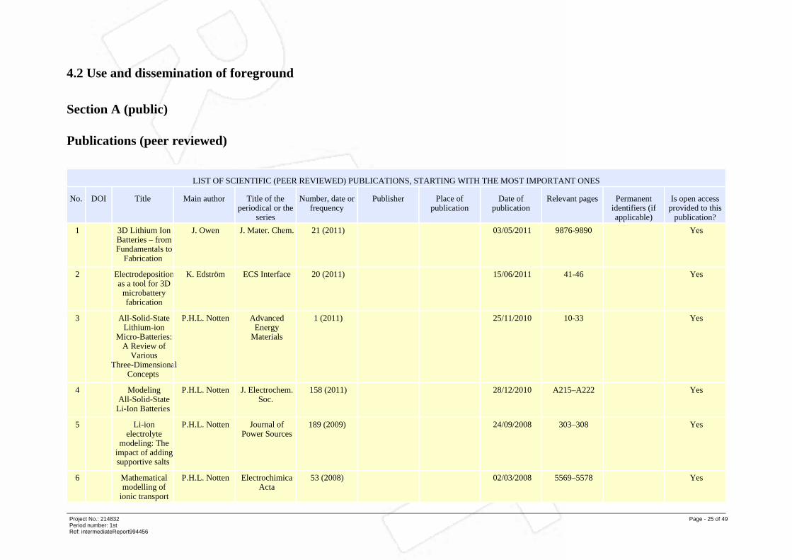
4.2 Use and dissemination of foreground
Section A (public)
Publications (peer reviewed)
LIST OF SCIENTIFIC (PEER REVIEWED) PUBLICATIONS, STARTING WITH THE MOST IMPORTANT ONES
No. DOI Title Main author Title of theperiodical or the
series
Number, date orfrequency
Publisher Place ofpublication
Date ofpublication
Relevant pages Permanentidentifiers (ifapplicable)
Is open accessprovided to this
publication?
1 3D Lithium IonBatteries – fromFundamentals to
Fabrication
J. Owen J. Mater. Chem. 21 (2011) 03/05/2011 9876-9890 Yes
2 Electrodepositionas a tool for 3D
microbatteryfabrication
K. Edström ECS Interface 20 (2011) 15/06/2011 41-46 Yes
3 All-Solid-StateLithium-ion
Micro-Batteries:A Review of
VariousThree-Dimensional
Concepts
P.H.L. Notten AdvancedEnergy
Materials
1 (2011) 25/11/2010 10-33 Yes
4 ModelingAll-Solid-State
Li-Ion Batteries
P.H.L. Notten J. Electrochem.Soc.
158 (2011) 28/12/2010 A215–A222 Yes
5 Li-ionelectrolyte
modeling: Theimpact of addingsupportive salts
P.H.L. Notten Journal ofPower Sources
189 (2009) 24/09/2008 303–308 Yes
6 Mathematicalmodelling of
ionic transport
P.H.L. Notten ElectrochimicaActa
53 (2008) 02/03/2008 5569–5578 Yes
Project No.: 214832Period number: 1stRef: intermediateReport994456
Page - 25 of 49

in the electrolyteof Li-ionbatteries
7 Modellingelectrodematerial
utilization in thetrench-model
3D-microbatteryby finite element
analysis
D. Brandell Journal ofPower Sources
195 (2010) 15/09/2010 6218-6224 Yes
8 Finite ElementModelling of
Ion Transport ina
3D-MicrobatteryElectrolyte
D. Brandell Solid StateIonics
192 (2011) 16/06/2011 279-283 Yes
9 ModellingPolymer
Electrolytes for3D-Microbatteries
using FiniteElementAnalysis
D.Brandell ElectrochimicaActa
57 (2011) 15/12/2011 237-243 Yes
10 Honeycomb-StructuredSilicon:
RemarkableMorphological
ChangesInduced by
Electrochemical(De)Lithiation
P.H.L. Notten AdvancedMaterials
23 (2011) 18/02/2011 1563–1566 Yes
11 The Effect ofShort-Chain
Amine Coatingson the
Performance ofLiFePO4 Li-Ion
BatteryCathodes
D. Brandell Electrochemicaland Solid State
Letters
12 (2009) 23/02/2009 A99-A101 Yes
12 TheMechanisms of
CapacityEnhancement in
D. Brandell J. Electrochem.Soc.
156 (2009) 29/06/2009 A720-A725 Yes
Project No.: 214832Period number: 1stRef: intermediateReport994456
Page - 26 of 49

LiFePO4Cathodesthrough
PolyetheramineCoating
13 Poly(etheramine) andcross-linked
poly(propyleneoxide) diacrylate
thin-filmpolymer
electrolyte for3D-microbatteries
D. Brandell ElectrochemistryCommunications
12 (2010) 25/08/2010 1498-1500 Yes
14 Branchedpolyethylene/poly(ethylene
oxide) as a hostmatrix for Li-ion
batteryelectrolytes: an
MD study
D. Brandell ElectrochimicaActa
57 (2011) 15/12/2011 228-236 Yes
15 3-DMicrobatteryElectrolyte bySelf-Assemblyof Oligomers
D. Brandell Solid StateIonics
198 (2011) 19/09/2011 26-31 Yes
16 Conformalelectrodeposition
of manganesedioxide ontoreticulated
vitreous carbonfor 3D
microbatteryapplications
J. Owen J. Mater. Chem. 21 (2011) 03/05/2011 10153-10159 Yes
17 How theelectrolyte limitsfast discharge innanostructuredbatteries and
supercapacitors
J. Owen ElectrochemistryCommunications
11 (2009) 16/09/2009 2089-2092 Yes
18 In situ growth ofpolymer
electrolytes on
J.Owen Electrochem.Communications
11 (2009) 15/10/2009 2320-2323 Yes
Project No.: 214832Period number: 1stRef: intermediateReport994456
Page - 27 of 49

lithium ionelectrodesurfaces
19 In situ NeutronDepth Profiling:a powerful newmethod to probelithium transport
inmicro-batteries
P.H.L. Notten AdvancedMaterials
23 (2011) 01/08/2011 4104-4106 Yes
20 Galvanostaticelectrodeposition
of aluminiumnano-rods for
Li-ionthree-dimensional
micro-batterycurrent
collectors
KristinaEdström
ElectrochimicaActa
56 (2011) 30/03/2011 3203-3208 Yes
21 A solid state 3-Dmicrobattery
based on Cu2Sbnano-pillar
anodes
D. Brandell Solid StateIonics
doi:10.1016/j.ssi.2011.11.005 26/11/2011 xxxx-yyyy Yes
22 Self-supportedthree
dimensionalnanoelectrodes
for microbatteryapplications
P. Simon Nano Letters 9 (2009) 15/09/2009 3230-3233 Yes
23 High ratecapability pure
Sn-basednano-architectured
electrodeassembly forrechargeable
lithium batteries
P. Simon J. PowerSources
188 (2009) 15/03/2009 578-582 Yes
24 Electrodepositionof Cu2Sb as
anode materialfor 3
dimensionalLi-ion
K. Edström J. Mater. Res. 25 (2010) 15/08/2010 1485-1491 Yes
Project No.: 214832Period number: 1stRef: intermediateReport994456
Page - 28 of 49
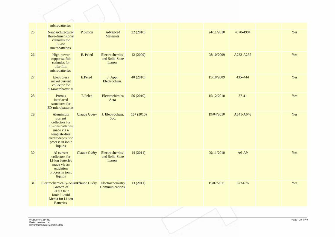
microbatteries
25 Nanoarchitecturedthree-dimensional
cathodes forLi-ion
microbatteries
P.Simon AdvancedMaterials
22 (2010) 24/11/2010 4978-4984 Yes
26 High-powercopper sulfidecathodes for
thin-filmmicrobatteries
E. Peled Electrochemicaland Solid-State
Letters
12 (2009) 08/10/2009 A232-A235 Yes
27 Electrolessnickel currentcollector for
3D-microbatteries
E.Peled J. Appl.Electrochem.
40 (2010) 15/10/2009 435–444 Yes
28 Porousinterlaced
structures for3D-microbatteries
E.Peled ElectrochimicaActa
56 (2010) 15/12/2010 37-41 Yes
29 Aluminiumcurrent
collectors forLi-ions batteries
made via atemplate-free
electrodepositionprecess in ionic
liquids
Claude Guéry J. Electrochem.Soc.
157 (2010) 19/04/2010 A641-A646 Yes
30 Al currentcollectors for
Li-ion batteriesmade via an
oxidationprocess in ionic
liquids
Claude Guéry Electrochemicaland Solid-State
Letters
14 (2011) 09/11/2010 A6-A9 Yes
31 Electrochemically-AssistedGrowth of
LiFePO4 inIonic Liquid
Media for Li-ionBatteries
Claude Guéry ElectrochemistryCommunications
13 (2011) 15/07/2011 673-676 Yes
Project No.: 214832Period number: 1stRef: intermediateReport994456
Page - 29 of 49

LIST OF DISSEMINATION ACTIVITIES
No. Type of activities Main Leader Title Date Place Type of audience Size of audience Countries addressed
1 Websites/Applications
UPPSALAUNIVERSITET
www.SUPERLION.eu 05/03/2009 Uppsala Scientificcommunity (higher
education,Research) -
Industry - Civilsociety - Policymakers - Medias
9999 all
2 Videos UPPSALAUNIVERSITET
3-D MicrobatteryResearch
10/01/2011 Uppsala UniversityScience Museum
Scientificcommunity (higher
education,Research) -
Industry - Civilsociety - Policymakers - Medias
9999 Sweden and touriststo Sweden
3 Exhibitions UPPSALAUNIVERSITET
The Year ofChemistryExhibition
03/01/2011 MuseumGustavianum,
Uppsala University
Scientificcommunity (higher
education,Research) -
Industry - Civilsociety
9999 Sweden
4 Presentations UPPSALAUNIVERSITET
3D-Microbatteries 15/11/2010 Ångström Lab, UU Civil society 100 Sweden's HighSchool science
teachers
5 Presentations UPPSALAUNIVERSITET
3D-Microbatteries 02/06/2011 Ångström Lab, UU Scientificcommunity (higher
education,Research) - Civil
society
50 USA collegeteachers
6 Presentations UPPSALAUNIVERSITET
3D-Microbatteries 16/02/2011 Uppsala University Scientificcommunity (higher
education,Research) -
Industry - Policymakers
30 Canada (Yukon)
7 Presentations UNIVERSITY OFSOUTHAMPTON
Li-Batteries andMicropower
09/11/2009 Science Cafe,Southampton
University
Scientificcommunity (higher
education,Research)
80 UK (Southamptonstudents)
8 Presentations UNIVERSITY OF Microbattery 10/04/2009 Southampton Scientific 250 UK (John Owen:
Project No.: 214832Period number: 1stRef: intermediateReport994456
Page - 30 of 49
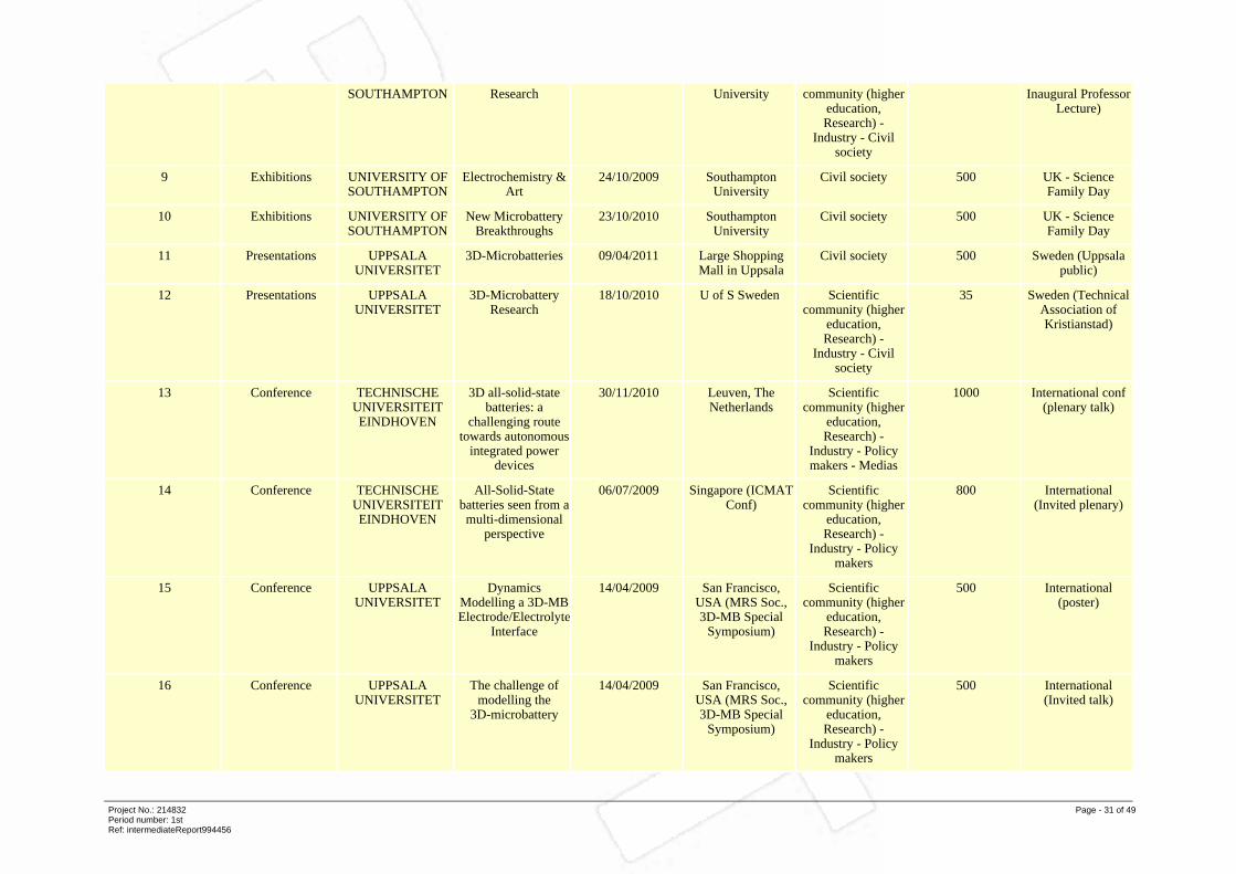
SOUTHAMPTON Research University community (highereducation,Research) -
Industry - Civilsociety
Inaugural ProfessorLecture)
9 Exhibitions UNIVERSITY OFSOUTHAMPTON
Electrochemistry &Art
24/10/2009 SouthamptonUniversity
Civil society 500 UK - ScienceFamily Day
10 Exhibitions UNIVERSITY OFSOUTHAMPTON
New MicrobatteryBreakthroughs
23/10/2010 SouthamptonUniversity
Civil society 500 UK - ScienceFamily Day
11 Presentations UPPSALAUNIVERSITET
3D-Microbatteries 09/04/2011 Large ShoppingMall in Uppsala
Civil society 500 Sweden (Uppsalapublic)
12 Presentations UPPSALAUNIVERSITET
3D-MicrobatteryResearch
18/10/2010 U of S Sweden Scientificcommunity (higher
education,Research) -
Industry - Civilsociety
35 Sweden (TechnicalAssociation ofKristianstad)
13 Conference TECHNISCHEUNIVERSITEITEINDHOVEN
3D all-solid-statebatteries: a
challenging routetowards autonomous
integrated powerdevices
30/11/2010 Leuven, TheNetherlands
Scientificcommunity (higher
education,Research) -
Industry - Policymakers - Medias
1000 International conf(plenary talk)
14 Conference TECHNISCHEUNIVERSITEITEINDHOVEN
All-Solid-Statebatteries seen from amulti-dimensional
perspective
06/07/2009 Singapore (ICMATConf)
Scientificcommunity (higher
education,Research) -
Industry - Policymakers
800 International(Invited plenary)
15 Conference UPPSALAUNIVERSITET
DynamicsModelling a 3D-MBElectrode/Electrolyte
Interface
14/04/2009 San Francisco,USA (MRS Soc.,3D-MB Special
Symposium)
Scientificcommunity (higher
education,Research) -
Industry - Policymakers
500 International(poster)
16 Conference UPPSALAUNIVERSITET
The challenge ofmodelling the
3D-microbattery
14/04/2009 San Francisco,USA (MRS Soc.,3D-MB Special
Symposium)
Scientificcommunity (higher
education,Research) -
Industry - Policymakers
500 International(Invited talk)
Project No.: 214832Period number: 1stRef: intermediateReport994456
Page - 31 of 49
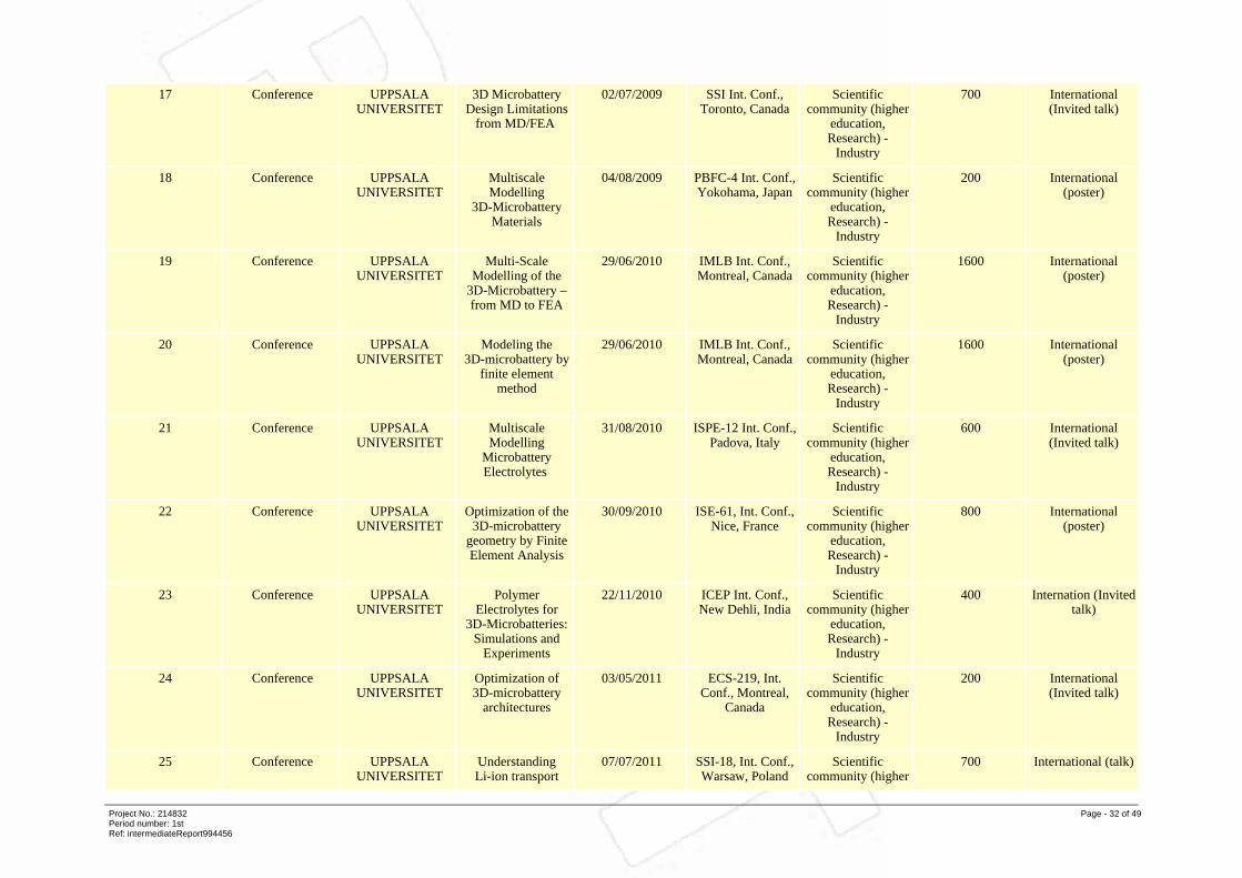
17 Conference UPPSALAUNIVERSITET
3D MicrobatteryDesign Limitations
from MD/FEA
02/07/2009 SSI Int. Conf.,Toronto, Canada
Scientificcommunity (higher
education,Research) -
Industry
700 International(Invited talk)
18 Conference UPPSALAUNIVERSITET
MultiscaleModelling
3D-MicrobatteryMaterials
04/08/2009 PBFC-4 Int. Conf.,Yokohama, Japan
Scientificcommunity (higher
education,Research) -
Industry
200 International(poster)
19 Conference UPPSALAUNIVERSITET
Multi-ScaleModelling of the
3D-Microbattery –from MD to FEA
29/06/2010 IMLB Int. Conf.,Montreal, Canada
Scientificcommunity (higher
education,Research) -
Industry
1600 International(poster)
20 Conference UPPSALAUNIVERSITET
Modeling the3D-microbattery by
finite elementmethod
29/06/2010 IMLB Int. Conf.,Montreal, Canada
Scientificcommunity (higher
education,Research) -
Industry
1600 International(poster)
21 Conference UPPSALAUNIVERSITET
MultiscaleModelling
MicrobatteryElectrolytes
31/08/2010 ISPE-12 Int. Conf.,Padova, Italy
Scientificcommunity (higher
education,Research) -
Industry
600 International(Invited talk)
22 Conference UPPSALAUNIVERSITET
Optimization of the3D-microbattery
geometry by FiniteElement Analysis
30/09/2010 ISE-61, Int. Conf.,Nice, France
Scientificcommunity (higher
education,Research) -
Industry
800 International(poster)
23 Conference UPPSALAUNIVERSITET
PolymerElectrolytes for
3D-Microbatteries:Simulations and
Experiments
22/11/2010 ICEP Int. Conf.,New Dehli, India
Scientificcommunity (higher
education,Research) -
Industry
400 Internation (Invitedtalk)
24 Conference UPPSALAUNIVERSITET
Optimization of3D-microbattery
architectures
03/05/2011 ECS-219, Int.Conf., Montreal,
Canada
Scientificcommunity (higher
education,Research) -
Industry
200 International(Invited talk)
25 Conference UPPSALAUNIVERSITET
UnderstandingLi-ion transport
07/07/2011 SSI-18, Int. Conf.,Warsaw, Poland
Scientificcommunity (higher
700 International (talk)
Project No.: 214832Period number: 1stRef: intermediateReport994456
Page - 32 of 49
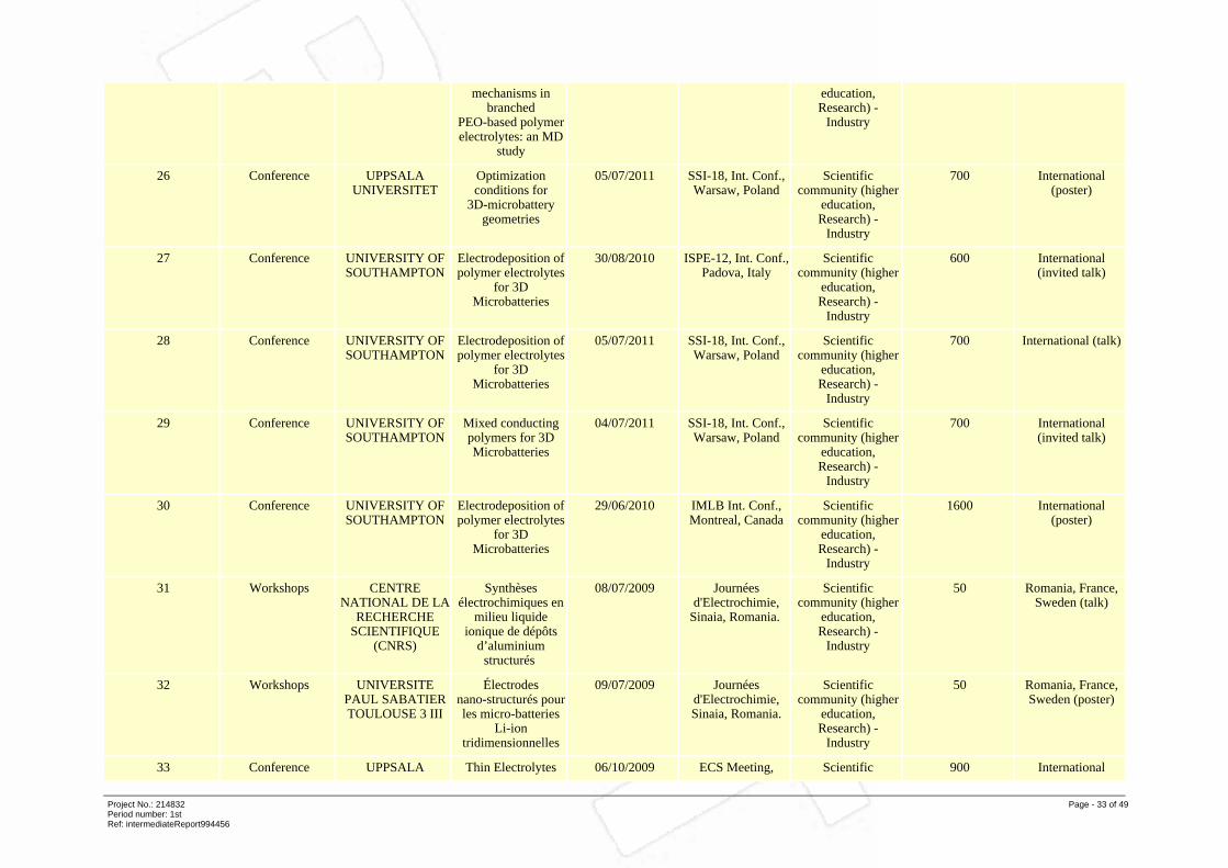
mechanisms inbranched
PEO-based polymerelectrolytes: an MD
study
education,Research) -
Industry
26 Conference UPPSALAUNIVERSITET
Optimizationconditions for
3D-microbatterygeometries
05/07/2011 SSI-18, Int. Conf.,Warsaw, Poland
Scientificcommunity (higher
education,Research) -
Industry
700 International(poster)
27 Conference UNIVERSITY OFSOUTHAMPTON
Electrodeposition ofpolymer electrolytes
for 3DMicrobatteries
30/08/2010 ISPE-12, Int. Conf.,Padova, Italy
Scientificcommunity (higher
education,Research) -
Industry
600 International(invited talk)
28 Conference UNIVERSITY OFSOUTHAMPTON
Electrodeposition ofpolymer electrolytes
for 3DMicrobatteries
05/07/2011 SSI-18, Int. Conf.,Warsaw, Poland
Scientificcommunity (higher
education,Research) -
Industry
700 International (talk)
29 Conference UNIVERSITY OFSOUTHAMPTON
Mixed conductingpolymers for 3DMicrobatteries
04/07/2011 SSI-18, Int. Conf.,Warsaw, Poland
Scientificcommunity (higher
education,Research) -
Industry
700 International(invited talk)
30 Conference UNIVERSITY OFSOUTHAMPTON
Electrodeposition ofpolymer electrolytes
for 3DMicrobatteries
29/06/2010 IMLB Int. Conf.,Montreal, Canada
Scientificcommunity (higher
education,Research) -
Industry
1600 International(poster)
31 Workshops CENTRENATIONAL DE LA
RECHERCHESCIENTIFIQUE
(CNRS)
Synthèsesélectrochimiques en
milieu liquideionique de dépôts
d’aluminiumstructurés
08/07/2009 Journéesd'Electrochimie,
Sinaia, Romania.
Scientificcommunity (higher
education,Research) -
Industry
50 Romania, France,Sweden (talk)
32 Workshops UNIVERSITEPAUL SABATIERTOULOUSE 3 III
Électrodesnano-structurés pourles micro-batteries
Li-iontridimensionnelles
09/07/2009 Journéesd'Electrochimie,Sinaia, Romania.
Scientificcommunity (higher
education,Research) -
Industry
50 Romania, France,Sweden (poster)
33 Conference UPPSALA Thin Electrolytes 06/10/2009 ECS Meeting, Scientific 900 International
Project No.: 214832Period number: 1stRef: intermediateReport994456
Page - 33 of 49
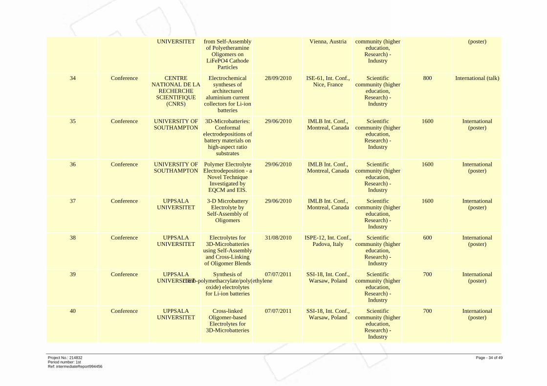
UNIVERSITET from Self-Assemblyof Polyetheramine
Oligomers onLiFePO4 Cathode
Particles
Vienna, Austria community (highereducation,Research) -
Industry
(poster)
34 Conference CENTRENATIONAL DE LA
RECHERCHESCIENTIFIQUE
(CNRS)
Electrochemicalsyntheses ofarchitectured
aluminium currentcollectors for Li-ion
batteries
28/09/2010 ISE-61, Int. Conf.,Nice, France
Scientificcommunity (higher
education,Research) -
Industry
800 International (talk)
35 Conference UNIVERSITY OFSOUTHAMPTON
3D-Microbatteries:Conformal
electrodepositions ofbattery materials on
high-aspect ratiosubstrates
29/06/2010 IMLB Int. Conf.,Montreal, Canada
Scientificcommunity (higher
education,Research) -
Industry
1600 International(poster)
36 Conference UNIVERSITY OFSOUTHAMPTON
Polymer ElectrolyteElectrodeposition - a
Novel TechniqueInvestigated byEQCM and EIS.
29/06/2010 IMLB Int. Conf.,Montreal, Canada
Scientificcommunity (higher
education,Research) -
Industry
1600 International(poster)
37 Conference UPPSALAUNIVERSITET
3-D MicrobatteryElectrolyte by
Self-Assembly ofOligomers
29/06/2010 IMLB Int. Conf.,Montreal, Canada
Scientificcommunity (higher
education,Research) -
Industry
1600 International(poster)
38 Conference UPPSALAUNIVERSITET
Electrolytes for3D-Microbatteries
using Self-Assemblyand Cross-Linkingof Oligomer Blends
31/08/2010 ISPE-12, Int. Conf.,Padova, Italy
Scientificcommunity (higher
education,Research) -
Industry
600 International(poster)
39 Conference UPPSALAUNIVERSITET
Synthesis ofcomb-polymethacrylate/poly(ethylene
oxide) electrolytesfor Li-ion batteries
07/07/2011 SSI-18, Int. Conf.,Warsaw, Poland
Scientificcommunity (higher
education,Research) -
Industry
700 International(poster)
40 Conference UPPSALAUNIVERSITET
Cross-linkedOligomer-basedElectrolytes for
3D-Microbatteries
07/07/2011 SSI-18, Int. Conf.,Warsaw, Poland
Scientificcommunity (higher
education,Research) -
Industry
700 International(poster)
Project No.: 214832Period number: 1stRef: intermediateReport994456
Page - 34 of 49

41 Conference UNIVERSITY OFSOUTHAMPTON
Conformalelectrodeposition ofbattery materials onporous 3D substrates
12/10/2010 ECS-218, FallMeeting, LasVegas, USA
Scientificcommunity (higher
education,Research) -
Industry
1100 International (talk)
42 Conference UNIVERSITY OFSOUTHAMPTON
3D Microbatteries:Conformal
deposition of batterymaterials on porous
3D substrates
20/12/2010 RSC 30thAnniversary
Meeting, UCL,London, UK
Scientificcommunity (higher
education,Research) -
Industry
250 UK + internationalguests (talk)
43 Conference CENTRENATIONAL DE LA
RECHERCHESCIENTIFIQUE
(CNRS)
Electrochemically-AssistedSynthesis of
LiFePO4 in IonicLiquid Media forLi-ion Batteries
28/09/2010 ISE-61, Int. Conf.,Nice, France
Scientificcommunity (higher
education,Research) -
Industry
800 International (talk)
44 Conference CENTRENATIONAL DE LA
RECHERCHESCIENTIFIQUE
(CNRS)
Electrochemical-basedsynthesis in Ionic
Liquids:applications forstructured active
electrodes
28/04/2011 MRS SpringMeeting,San
Francisco, USA
Scientificcommunity (higher
education,Research) -
Industry
1100 International(invited talk)
45 Conference UNIVERSITEPAUL SABATIERTOULOUSE 3 III
A high aspect ratioCu2Sb electrode
coated with asilane-based
polymer film to beused in a 3D micro
14/04/2009 San Francisco,USA (MRS Soc.,3D-MB Special
Symposium)
Scientificcommunity (higher
education,Research) -
Industry
500 International(invited talk)
46 Conference UNIVERSITEPAUL SABATIERTOULOUSE 3 III
Design offree-standing
electrodes for 3Darchitectured Li-ion
micro-batteries
01/12/2009 MRS Fall Meeting,Boston, USA
Scientificcommunity (higher
education,Research) -
Industry
1000 International (talk)
47 Workshops UNIVERSITY OFSOUTHAMPTON
High-throughputStudies of
ElectrodepositedCathodes and
Anodes
14/06/2011 LiBD-4 Workshop,Arcachon, France
Scientificcommunity (higher
education,Research) -
Industry
180 International(poster)
48 Conference UNIVERSITY OFSOUTHAMPTON
Electrodeposition ofMnO2 for 3Dmicrobatteries
06/10/2009 ECS Meeting,Vienna, Austria
Scientificcommunity (higher
education,Research) -
Industry
900 International(poster)
Project No.: 214832Period number: 1stRef: intermediateReport994456
Page - 35 of 49

49 Workshops CENTRENATIONAL DE LA
RECHERCHESCIENTIFIQUE
(CNRS)
Synthèseélectrochimiquement
assistée en milieuliquide ionique deLiMPO4 avec M =
Fe
20/10/2009 Ecole Galerne2009, Amiens,
France
Scientificcommunity (higher
education,Research) -
Industry
60 France (poster)
50 Conference UNIVERSITEPAUL SABATIERTOULOUSE 3 III
Nano-architectured3-dimensional
electrodes for Li-ionmicrobatteries
29/06/2010 IMLB Int. Conf.,Montreal, Canada
Scientificcommunity (higher
education,Research) -
Industry
1600 International(poster)
51 Conference UNIVERSITEPAUL SABATIERTOULOUSE 3 III
Nanostructuredanodes for 3D
Li-ionmicrobatteries based
on anano-architectured
copper CC
29/06/2010 IMLB Int. Conf.,Montreal, Canada
Scientificcommunity (higher
education,Research) -
Industry
1600 International(poster)
52 Conference UPPSALAUNIVERSITET
Towardsnano-structured
electrodes for Li-ion3D micro-batteries
29/06/2010 IMLB Int. Conf.,Montreal, Canada
Scientificcommunity (higher
education,Research) -
Industry
1600 International(poster)
53 Conference UPPSALAUNIVERSITET
Three-dimensionalarchitectures for
Li-ion micro-batteryelectrodes
05/07/2011 SSI-18, Int. Conf.,Warsaw, Poland
Scientificcommunity (higher
education,Research) -
Industry
700 International(poster)
54 Conference TEL AVIVUNIVERSITY
3D-Microbatteriesfor medical andtechnologicalapplication
08/09/2008 ISE-59 Meeting,Seville, Spain
Scientificcommunity (higher
education,Research) -
Industry
1200 International (talk)
55 Conference TEL AVIVUNIVERSITY
Nano-size materialsfor
3D-microbatteries
17/09/2008 EMNT-9, DeadSea, Israel,
Scientificcommunity (higher
education,Research) -
Industry
300 International (talk)
56 Conference TEL AVIVUNIVERSITY
Modified electrodematerials for
3D-microbatteries
29/06/2009 SSI Int. Conf.,Toronto, Canada
Scientificcommunity (higher
education,Research) -
Industry
700 International(Invited talk)
Project No.: 214832Period number: 1stRef: intermediateReport994456
Page - 36 of 49

57 Conference TEL AVIVUNIVERSITY
High-surface areaelectrode materials
for3D-microbatteries
21/09/2009 12th EuropeanConf. on Solid
State Chemistry,Munster, Germany
Scientificcommunity (higher
education,Research) -
Industry
500 International (talk)
58 Conference TEL AVIVUNIVERSITY
A closer look atthree-dimensional
microbatteries
06/10/2009 ECS Meeting,Vienna, Austria
Scientificcommunity (higher
education,Research) -
Industry
900 International(poster)
59 Conference TEL AVIVUNIVERSITY
High powerelectrodepositedcopper sulfide
thin-film cathodesfor
3D-microbatteries
13/12/2009 IMEC-14, TelAviv, Israel
Scientificcommunity (higher
education,Research) -
Industry
200 Israel +international guests
(invited talk)
60 Workshops TEL AVIVUNIVERSITY
Advanced materialsfor thin-film
3D-microbatteries
17/02/2010 5th AnnualInternational
ElectromaterialsScience
Symposium,Melbourne,Australia
Scientificcommunity (higher
education,Research) -
Industry
400 InternationalInvited talk)
61 Workshops TECHNISCHEUNIVERSITEITEINDHOVEN
All-solid-statebatteries: a
challenging routetowards
3D-integration
16/06/2011 LiBD-4 Workshop,Arcachon, France
Scientificcommunity (higher
education,Research) -
Industry
180 International(Invited talk)
62 Conference UNIVERSITY OFSOUTHAMPTON
3D Microbatteries 14/04/2009 San Francisco,USA (MRS Soc.,3D-MB Special
Symposium)
Scientificcommunity (higher
education,Research) -
Industry
500 International(invited talk)
63 Conference UNIVERSITY OFSOUTHAMPTON
ElectrolyteDepletion and 3D
Microbatteries
29/06/2010 IMLB Int. Conf.,Montreal, Canada
Scientificcommunity (higher
education,Research) -
Industry
1600 International (talk)
64 Conference UNIVERSITY OFSOUTHAMPTON
Smart design of 3DMicrobatteries
28/09/2010 ISE-61, Int. Conf.,Nice, France
Scientificcommunity (higher
education,Research) -
Industry
800 International (talk)
Project No.: 214832Period number: 1stRef: intermediateReport994456
Page - 37 of 49
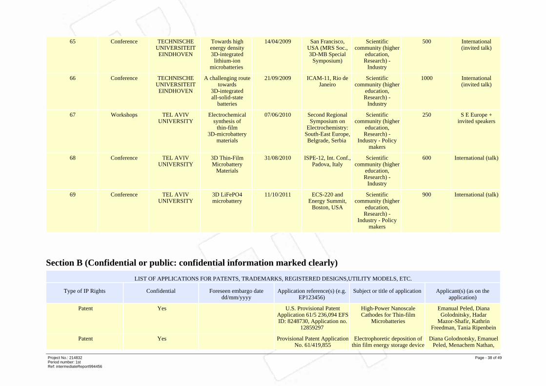
65 Conference TECHNISCHEUNIVERSITEITEINDHOVEN
Towards highenergy density3D-integrated
lithium-ionmicrobatteries
14/04/2009 San Francisco,USA (MRS Soc.,3D-MB Special
Symposium)
Scientificcommunity (higher
education,Research) -
Industry
500 International(invited talk)
66 Conference TECHNISCHEUNIVERSITEITEINDHOVEN
A challenging routetowards
3D-integratedall-solid-state
batteries
21/09/2009 ICAM-11, Rio deJaneiro
Scientificcommunity (higher
education,Research) -
Industry
1000 International(invited talk)
67 Workshops TEL AVIVUNIVERSITY
Electrochemicalsynthesis of
thin-film3D-microbattery
materials
07/06/2010 Second RegionalSymposium on
Electrochemistry:South-East Europe,Belgrade, Serbia
Scientificcommunity (higher
education,Research) -
Industry - Policymakers
250 S E Europe +invited speakers
68 Conference TEL AVIVUNIVERSITY
3D Thin-FilmMicrobattery
Materials
31/08/2010 ISPE-12, Int. Conf.,Padova, Italy
Scientificcommunity (higher
education,Research) -
Industry
600 International (talk)
69 Conference TEL AVIVUNIVERSITY
3D LiFePO4microbattery
11/10/2011 ECS-220 andEnergy Summit,
Boston, USA
Scientificcommunity (higher
education,Research) -
Industry - Policymakers
900 International (talk)
Section B (Confidential or public: confidential information marked clearly)
LIST OF APPLICATIONS FOR PATENTS, TRADEMARKS, REGISTERED DESIGNS,UTILITY MODELS, ETC.
Type of IP Rights Confidential Foreseen embargo datedd/mm/yyyy
Application reference(s) (e.g.EP123456)
Subject or title of application Applicant(s) (as on theapplication)
Patent Yes U.S. Provisional PatentApplication 61/5 236,094 EFSID: 8248730, Application no.
12859297
High-Power NanoscaleCathodes for Thin-film
Microbatteries
Emanual Peled, DianaGolodnitsky, Hadar
Mazor-Shafir, KathrinFreedman, Tania Ripenbein
Patent Yes Provisional Patent ApplicationNo. 61/419,855
Electrophoretic deposition ofthin film energy storage device
Diana Golodnotsky, EmanuelPeled, Menachem Nathan,
Project No.: 214832Period number: 1stRef: intermediateReport994456
Page - 38 of 49

Gilat Ardel, HadarMazor-Shafir, Roni Hadar,
Svetlana Menkin, TaniaRipenbein, Kathrin Freedman
OVERVIEW TABLE WITH EXPLOITABLE FOREGROUND
Type of ExploitableForeground
Description ofExploitableForeground
Confidential Foreseen embargodate dd/mm/yyyy
Exploitableproduct(s) ormeasure(s)
Sector(s) ofapplication
Timetable forcommercial use or
any other use
Patents or other IPRexploitation(licences)
Owner and OtherBeneficiary(s) involved
Generaladvancement of
knowledge
A new generalawareness that
efforts to synthesise3D-architectured
electrodes for3D-MB
applications can betotally wasted in
terms of improvedfootprint capacity ifproper attention is
not paid to thesubtle relationship
between 3Dgeometrical design
and materialproperties - as laid
out in themodelling reportsfrom the project.
No Applicable to ALLfuture 3D-MB
devices
As above N/A N/A N/A
Commercialexploitation ofR&D results
1. Deposition ofLiFePO4 onto
reticulated vitreouscarbon. 2.
Self-assembly ofsurfactant
oligomers onLiFePO4 particles.3. Sb and Cu2Sb
negative electrodeselectrodeposited
onto Cumicro-trenches. 4.
LiFePO4 and
Yes Can be exploited infuture 3D-MB
products.
3D micro-batteries Uncertain - moreR&D needed.
See elsewhere inreport
Patenttakers and otherindustrial partners in
the project.
Project No.: 214832Period number: 1stRef: intermediateReport994456
Page - 39 of 49
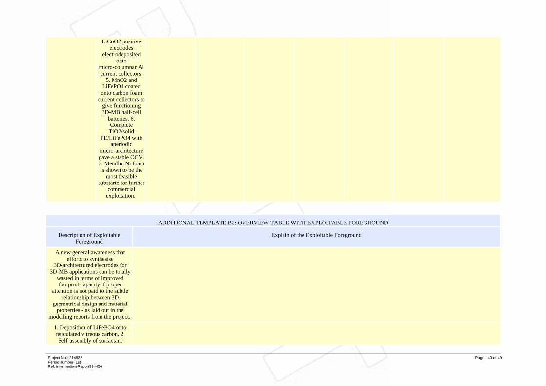
LiCoO2 positiveelectrodes
electrodepositedonto
micro-columnar Alcurrent collectors.
5. MnO2 andLiFePO4 coated
onto carbon foamcurrent collectors to
give functioning3D-MB half-cell
batteries. 6.CompleteTiO2/solid
PE/LiFePO4 withaperiodic
micro-architecturegave a stable OCV.7. Metallic Ni foamis shown to be the
most feasiblesubstarte for further
commercialexploitation.
ADDITIONAL TEMPLATE B2: OVERVIEW TABLE WITH EXPLOITABLE FOREGROUND
Description of ExploitableForeground
Explain of the Exploitable Foreground
A new general awareness thatefforts to synthesise
3D-architectured electrodes for3D-MB applications can be totally
wasted in terms of improvedfootprint capacity if proper
attention is not paid to the subtlerelationship between 3D
geometrical design and materialproperties - as laid out in the
modelling reports from the project.
1. Deposition of LiFePO4 ontoreticulated vitreous carbon. 2.Self-assembly of surfactant
Project No.: 214832Period number: 1stRef: intermediateReport994456
Page - 40 of 49

oligomers on LiFePO4 particles. 3.Sb and Cu2Sb negative electrodes
electrodeposited onto Cumicro-trenches. 4. LiFePO4 and
LiCoO2 positive electrodeselectrodeposited onto
micro-columnar Al currentcollectors. 5. MnO2 and LiFePO4coated onto carbon foam current
collectors to give functioning3D-MB half-cell batteries. 6.
Complete TiO2/solid PE/LiFePO4with aperiodic micro-architecturegave a stable OCV. 7. Metallic Ni
foam is shown to be the mostfeasible substarte for further
commercial exploitation.
Project No.: 214832Period number: 1stRef: intermediateReport994456
Page - 41 of 49

4.3 Report on societal implications
A. Ethics
1. Did your project undergo an Ethics Review(and/or Screening)?
No
If Yes: have you described the progress ofcompliance with the relevant EthicsReview/Screening Requirements in the frameof the periodic/final reports?
2. Please indicate whether your project involved any of the following issues :
RESEARCH ON HUMANS
Did the project involve children? No
Did the project involve patients? No
Did the project involve persons not able toconsent?
No
Did the project involve adult healthyvolunteers?
No
Did the project involve Human geneticmaterial?
No
Did the project involve Human biologicalsamples?
No
Did the project involve Human datacollection?
No
RESEARCH ON HUMAN EMBRYO/FOETUS
Did the project involve Human Embryos? No
Did the project involve Human Foetal Tissue /Cells?
No
Did the project involve Human EmbryonicStem Cells (hESCs)?
No
Did the project on human Embryonic StemCells involve cells in culture?
No
Did the project on human Embryonic StemCells involve the derivation of cells fromEmbryos?
No
PRIVACY
Did the project involve processing of geneticinformation or personal data (eg. health,sexual lifestyle, ethnicity, political opinion,religious or philosophical conviction)?
No
Did the project involve tracking the locationor observation of people?
No
RESEARCH ON ANIMALS
Did the project involve research on animals? No
Project No.: 214832Period number: 1stRef: intermediateReport994456
Page - 42 of 49

Were those animals transgenic smalllaboratory animals?
No
Were those animals transgenic farm animals? No
Were those animals cloned farm animals? No
Were those animals non-human primates? No
RESEARCH INVOLVING DEVELOPING COUNTRIES
Did the project involve the use of localresources (genetic, animal, plant etc)?
No
Was the project of benefit to local community(capacity building, access to healthcare,education etc)?
Yes
DUAL USE
Research having direct military use No
Research having potential for terrorist abuse No
B. Workforce Statistics
3. Workforce statistics for the project: Please indicate in the table below the number of peoplewho worked on the project (on a headcount basis).
Type of Position Number of Women Number of Men
Scientific Coordinator 0 1
Work package leaders 2 4
Experienced researchers (i.e. PhD holders) 7 22
PhD student 4 4
Other 7 18
4. How many additional researchers (incompanies and universities) were recruitedspecifically for this project?
5
Of which, indicate the number of men: 4
Project No.: 214832Period number: 1stRef: intermediateReport994456
Page - 43 of 49

C. Gender Aspects
5. Did you carry out specific Gender EqualityActions under the project ?
No
6. Which of the following actions did you carry out and how effective were they?
Design and implement an equal opportunitypolicy
Not Applicable
Set targets to achieve a gender balance in theworkforce
Not Applicable
Organise conferences and workshops ongender
Not Applicable
Actions to improve work-life balance Not Applicable
Other:
7. Was there a gender dimension associatedwith the research content - i.e. whereverpeople were the focus of the research as, forexample, consumers, users, patients or intrials, was the issue of gender considered andaddressed?
No
If yes, please specify:
D. Synergies with Science Education
8. Did your project involve working withstudents and/or school pupils (e.g. open days,participation in science festivals and events,prizes/competitions or joint projects)?
Yes
If yes, please specify: See items 2, 3, 4, 7, 9 and 10 in List ofDissemination Activies
9. Did the project generate any scienceeducation material (e.g. kits, websites,explanatory booklets, DVDs)?
Yes
E. Interdisciplinarity
10. Which disciplines (see list below) are involved in your project?
Main discipline: 2.2 Electrical engineering, electronics [electricalengineering, electronics, communicationengineering and systems, computer engineering(hardware only) and other allied subjects]
Associated discipline: 3.2 Clinical medicine (anaesthesiology,paediatrics, obstetrics and gynaecology, internalmedicine, surgery, dentistry, neurology,psychiatry, radiology, therapeutics,otorhinolaryngology, ophthalmology)
Associated discipline: 1.3 Chemical sciences (chemistry, other allied
Project No.: 214832Period number: 1stRef: intermediateReport994456
Page - 44 of 49

subjects)
F. Engaging with Civil society and policy makers
11a. Did your project engage with societalactors beyond the research community? (if'No', go to Question 14)
Yes
11b. If yes, did you engage with citizens(citizens' panels / juries) or organised civilsociety (NGOs, patients' groups etc.)?
Yes - in determining what research should beperformed
11c. In doing so, did your project involveactors whose role is mainly to organise thedialogue with citizens and organised civilsociety (e.g. professional mediator;communication company, science museums)?
Yes
12. Did you engage with government / publicbodies or policy makers (includinginternational organisations)
Yes, in communicating /disseminating / using theresults of the project
13a. Will the project generate outputs(expertise or scientific advice) which could beused by policy makers?
Yes - as a secondary objective (please indicateareas below - multiple answer possible)
13b. If Yes, in which fields?
Agriculture No
Audiovisual and Media No
Budget No
Competition No
Consumers No
Culture No
Customs No
Development Economic and Monetary Affairs No
Education, Training, Youth Yes
Employment and Social Affairs No
Energy Yes
Enlargement No
Enterprise Yes
Environment Yes
External Relations No
External Trade No
Fisheries and Maritime Affairs No
Food Safety No
Foreign and Security Policy No
Project No.: 214832Period number: 1stRef: intermediateReport994456
Page - 45 of 49

Fraud No
Humanitarian aid No
Human rightsd No
Information Society Yes
Institutional affairs No
Internal Market No
Justice, freedom and security No
Public Health Yes
Regional Policy No
Research and Innovation Yes
Space No
Taxation No
Transport No
13c. If Yes, at which level? International level
G. Use and dissemination14. How many Articles werepublished/accepted for publication inpeer-reviewed journals?
31
To how many of these is open accessprovided?
31
How many of these are published in openaccess journals?
31
How many of these are published in openrepositories?
31
To how many of these is open access notprovided?
0
Please check all applicable reasons for not providing open access:
publisher's licensing agreement would notpermit publishing in a repository
No
no suitable repository available No
no suitable open access journal available No
no funds available to publish in an open accessjournal
No
lack of time and resources No
lack of information on open access No
If other - please specify
15. How many new patent applications('priority filings') have been made?("Technologically unique": multipleapplications for the same invention in
2
Project No.: 214832Period number: 1stRef: intermediateReport994456
Page - 46 of 49

different jurisdictions should be counted asjust one application of grant).
16. Indicate how many of the following Intellectual Property Rights were applied for (givenumber in each box).
Trademark 0
Registered design 0
Other 2
17. How many spin-off companies werecreated / are planned as a direct result of theproject?
0
Indicate the approximate number ofadditional jobs in these companies:
0
18. Please indicate whether your project has apotential impact on employment, incomparison with the situation before yourproject:
Difficult to estimate / not possible to quantify, Insmall and medium-sized enterprises
19. For your project partnership pleaseestimate the employment effect resultingdirectly from your participation in Full TimeEquivalent (FTE = one person workingfulltime for a year) jobs:
0Difficult to estimate / not possible to quantify
H. Media and Communication to the general public20. As part of the project, were any of thebeneficiaries professionals in communicationor media relations?
No
21. As part of the project, have anybeneficiaries received professional media /communication training / advice to improvecommunication with the general public?
No
22. Which of the following have been used to communicate information about your project tothe general public, or have resulted from your project?
Press Release Yes
Media briefing No
TV coverage / report No
Radio coverage / report Yes
Brochures /posters / flyers Yes
DVD /Film /Multimedia Yes
Coverage in specialist press Yes
Coverage in general (non-specialist) press Yes
Coverage in national press No
Project No.: 214832Period number: 1stRef: intermediateReport994456
Page - 47 of 49

Coverage in international press No
Website for the general public / internet Yes
Event targeting general public (festival,conference, exhibition, science café)
Yes
23. In which languages are the information products for the general public produced?
Language of the coordinator No
Other language(s) Yes
English Yes
Project No.: 214832Period number: 1stRef: intermediateReport994456
Page - 48 of 49
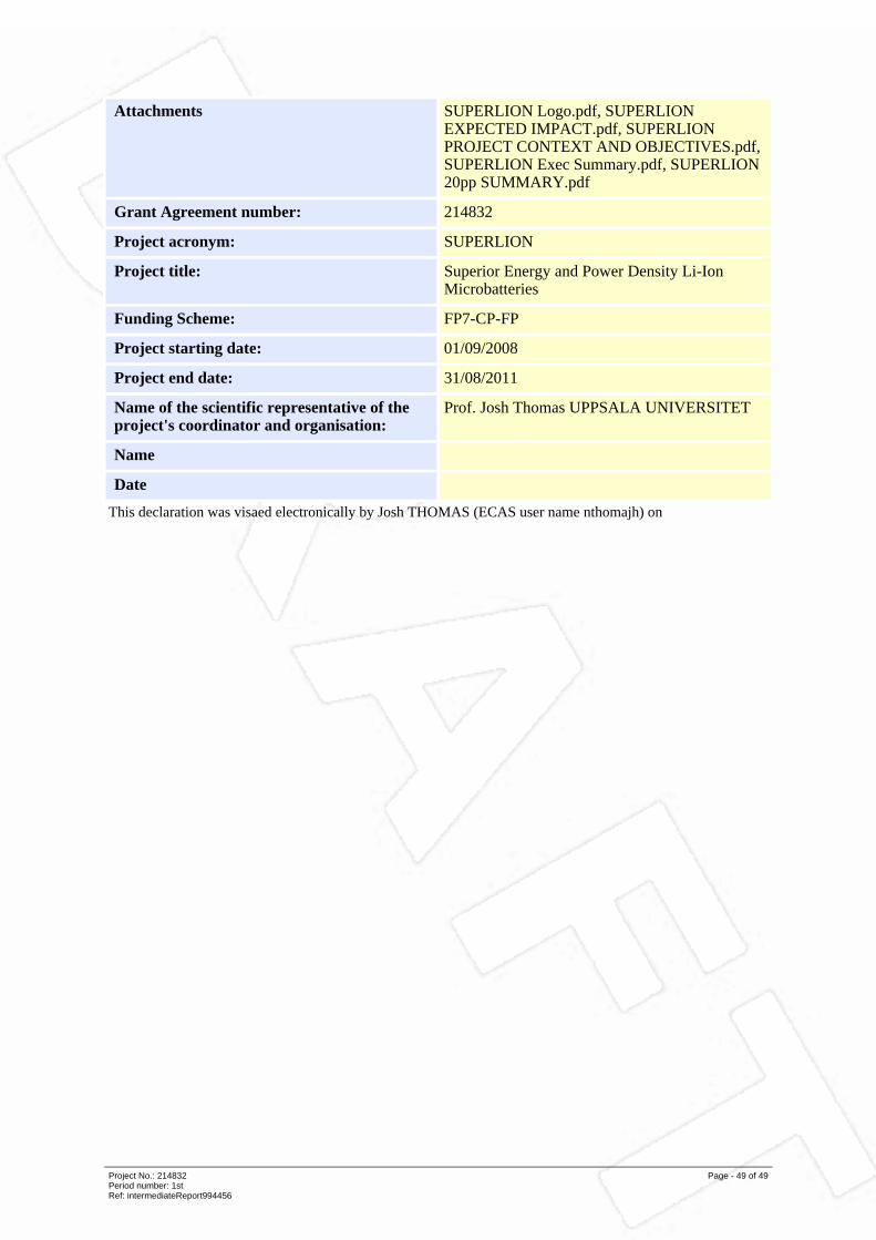
Attachments SUPERLION Logo.pdf, SUPERLIONEXPECTED IMPACT.pdf, SUPERLIONPROJECT CONTEXT AND OBJECTIVES.pdf,SUPERLION Exec Summary.pdf, SUPERLION20pp SUMMARY.pdf
Grant Agreement number: 214832
Project acronym: SUPERLION
Project title: Superior Energy and Power Density Li-IonMicrobatteries
Funding Scheme: FP7-CP-FP
Project starting date: 01/09/2008
Project end date: 31/08/2011
Name of the scientific representative of theproject's coordinator and organisation:
Prof. Josh Thomas UPPSALA UNIVERSITET
Name
Date
This declaration was visaed electronically by Josh THOMAS (ECAS user name nthomajh) on
Project No.: 214832Period number: 1stRef: intermediateReport994456
Page - 49 of 49