Final Progress Report to NASA Marshall Space Flight...
38
Final Progress Report to NASA Marshall Space Flight Center Dr. Robert Thom Non-Destructive Testing and Tribology Research Branch Mail code EH 13 MSFC ED 14 Huntsville AL 35812 COMPUTATIONAL ANALYSIS OF MISALIGNED HYBRID T HRUST BEARINGS FOR ADVANCED CRYOGENIC T URBO PUMPS NASA Grant NAG8-1395 BULK -FLOW ANALYSIS OF CRYOGENIC FLUID HYDROSTATIC/HYDRODYNAMIC THRUST BEARINGS ( P HASE II ) by Dr. Luis San Andrés Professor Turbomachinery Laboratory Mechanical Engineering Department, Texas A&M University College Station, TX 77845 January 2001
Transcript of Final Progress Report to NASA Marshall Space Flight...

Final Progress Report to NASA Marshall Space Flight Center
Dr. Robert Thom Non-Destructive Testing and Tribology Research Branch
Mail code EH 13 MSFC ED 14 Huntsville AL 35812
COMPUTATIONAL ANALYSIS OF MISALIGNED HYBRID THRUST BEARINGS FOR ADVANCED CRYOGENIC TURBO
PUMPS
NASA Grant NAG8-1395 BULK-FLOW ANALYSIS OF CRYOGENIC FLUID HYDROSTATIC/HYDRODYNAMIC
THRUST BEARINGS ( PHASE II )
by Dr. Luis San Andrés
Professor Turbomachinery Laboratory
Mechanical Engineering Department, Texas A&M University
College Station, TX 77845
January 2001
TABLE OF CONTENTS
page
EXECUTIVE SUMMARY i NOMENCLATURE iii LIST OF TABLES vii LIST OF FIGURES vii INTRODUCTION 1 BULK FLOW ANALYSIS 2 Perturbation analysis of the flow field 7 Zeroth-order bulk-flow equations on the film lands 8 First-order bulk-flow equations on the film lands 9 Zeroth- and first-order flow equations at a bearing recess 10 Fluid film axial force and restoring moments 10 Fluid film dynamic axial force and moment coefficients 11 Force and moment coefficients at the statically aligned condition 13 The numerical solution procedure 14 THE COMPUTER PROGRAM HYDROTHRUSTM 14 PREDICTIONS AND DISCUSSION 15 Force and moment coefficients for the aligned hybrid thrust bearing 18 Effect of shaft static misalignment on thrust bearing performance 19 CONCLUSIONS 22 REFERENCES 23 Figures 3-11 24-28

i
COMPUTATIONAL ANALYSIS OF MISALIGNED HYBRID THRUST BEARINGS FOR ADVANCED CRYOGENIC TURBO PUMPS
EXECUTIVE SUMMARY The report details an extended computational bulk-flow analysis for prediction of the static and dynamic force and moment performance of angled injection, orifice-compensated hydrostatic / hydrodynamic thrust bearings. The motion of the cryogenic fluid within the thin film lands of a thrust bearing is governed by a set of bulk-flow mass and momentum conservation and energy transport equations. Mass flow conservation and a simple model for momentum transport within the hydrostatic bearing recesses are also accounted for. The bulk-flow model includes flow turbulence with fluid inertia advection, Coriolis and centrifugal acceleration effects on the bearing recesses and film lands. The cryogenic fluid properties are obtained from realistic thermophysical equations of state. A perturbation analysis leads to zeroth-order nonlinear equations governing the fluid flow for the thrust bearing operating at a static equilibrium position with misalignment, and first-order linear equations describing the perturbed fluid flow for small amplitude shaft motions in the axial direction and shaft angulations around two principal axes. Numerical solution to the zeroth-order flow field equations renders the bearing flow rate, thrust load, restoring moments, drag torque and power dissipation. Solution to the first-order equations determines 27 force and moment coefficients, i.e. nine stiffness, nine damping and nine inertia coefficients due to shaft displacements and angulations. The computational method implements established algorithms and generic subprograms available from prior developments. The enhanced Fortran90 program, HYDROTHRUSTM, runs as a console application on Windows 95/NT personal computers. The program, help files and examples are available through Texas A&M University Technology License Office. The effects of shaft misalignment on the static and dynamic force and moment performance of a refrigerant hybrid thrust bearing are evaluated at an optimal operating condition. The results complement earlier predictions advanced in Phase I of the project. The axial force/displacement stiffness coefficient and the direct moment/angle stiffness coefficients show an optimum value for a certain load (recess pressure ratio) while the damping coefficient steadily increases with the applied load. As the misalignment angle increases, both moment and force coefficients due to shaft axial displacements and angulations also increase. A whirl frequency ratio equal to 0.50 is predicted for most operating conditions. That is, thrust hybrid bearings offer the same limited stability characteristics as hydrodynamic thrust bearings when undergoing self-excited shaft angular motions. The analysis and computational capability to predict the performance of (flexure pivot) tilting pad hybrid bearings were not finalized due to lack of resources and inadequate planning. This important objective will be addressed in the near future with the support of the TAMU Turbomachinery Laboratory.

ii
The lack of experimental data for the performance of hybrid thrust bearings under operating conditions similar to those of cryogenic turbo pumps continues to impair the validation of the advanced computational model. Rocket engine manufacturers will soon advance in the practice and implementation of an “all fluid film bearing technology,” thus releasing reliable test data to benchmark the model, and most importantly, demonstrating the superior performance of externally pressurized fluid film bearings under stringent and realistic operating conditions.
iii
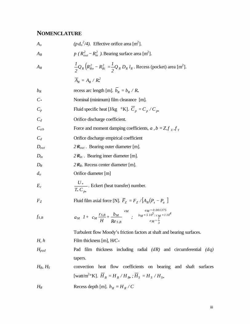
NOMENCLATURE
Ao (πdo2/4). Effective orifice area [m2].
AB ).RR( 2in
2out −π Bearing surface area [m2].
AR ( ) RRR2Ri
2RoR lD
21
RR21
ΘΘ =− . Recess (pocket) area [m2].
2*RR R/AA =
bR recess arc length [m]. *RR R/bb =
C* Nominal (minimum) film clearance [m].
Cp Fluid specific heat [J/kg ⋅ °K]. *ppp C/CC =
Cd Orifice discharge coefficient.
Cαβ Force and moment damping coefficients, YXZ φφβα ,,, =
Cd Orifice discharge empirical coefficient
Dout 2⋅Rout . Bearing outer diameter [m].
Din 2⋅Rin . Bearing inner diameter [m].
DR 2⋅RR. Recess center diameter [m].
do Orifice diameter [m]
Ec *p*
*
CTU
. Eckert (heat transfer) number.
FZ Fluid film axial force [N]. ( )[ ]asBZZ PPA/FF −=
fS,B 31
= eM
4101 = cM;5105 = bM
0.001375 = aM
B,S
MBS,M
eM
M ;Reb +
Hr
c + 1a ⋅⋅
Turbulent flow Moody’s friction factors at shaft and bearing surfaces.
H, h Film thickness [m], H/C*
Hpad Pad film thickness including radial (δR) and circumferential (δθ)
tapers.
HB, HS convection heat flow coefficients on bearing and shaft surfaces
[watt/m2°K]. *SSS*BBB H/HH;H/HH ==
HR Recess depth [m]. C/Hh RR =

iv
YX
hhhZ φφ ,, =1, -r sinθ, r cosθ. Film perturbations in axial and angular directions.
Kαβ Force and moment stiffness coefficients, YXZ φφβα ,,, =
Keq Equivalent moment coefficient for stability prediction [Nm/rad].
L (Rout - Rin). Bearing radial length [m].
lR (RRo - RRi). Recess radial length [m].
M Bearing mass flow rate [kg/s].
MRin, MRout Mass flow rates through inner and outer diameters of bearing [kg/s].
MR Mass flow through recess orifice [kg/s]. ( )***RR RCU/MM ρ=
MX, MY Restoring moments on thrust collar [N.m]
MΓ ∫ ⋅Γ Γηρ dUHrr
. Mass flow from recess boundary into to film lands
[kg/s]. ( )*** RCU/MM ρΓΓ =
Mαβ Force and moment inertia coefficients, YXZ φφβα ,,, =
Nrec Number of hydrostatic recesses (pockets) on bearing pad.
Npad Number of pads on bearing.
P, P Fluid pressure [N/m2], (P-Pa)/(Ps-Pa).
PR, Ps Recess pressure, supply pressure [N/m2].
+−ReRe P,P Edge recess pressures [N/m2].
PDin , PDout Fluid pressures at inner and outer bearing diameters [N/m2].
Pa Characteristic pressure, MIN[PDin , PDout] [N/m2].
Pdyn ½ ρ(Ω RR)2. Pressure due to centrifugal inertia effect at pocket radius
QBS QB + QS. Radial heat flow through bearing, QB= HB(T-TB), and shaft,
QS=HS(T-TS), surfaces [watt/m2].
R, r Radial coordinate [m], *R/R .
*R Rout. Characteristic bearing radius [m].
Re ( )./CR *** µΩρ Nominal circumferential flow Reynolds number.
Rep ( )./CU *** µρ Nominal pressure flow Reynolds number.
*pRe ( )*p R/CRe . Nominal modified pressure flow Reynolds number.
Res ( )*p*2
* Re/C σµωρ = . Squeeze film Reynolds number.

v
ReB, ReS (ρH/µ) [UR2 + Uθ
2 ]1/2, (ρH/µ) [UR2 + (Uθ -ΩR)2 ]1/2
Flow Reynolds numbers relative to bearing and shaft surfaces.
rS, rB Roughness depths of shaft and bearing surfaces [m].
s R/RR. Local radial coordinate from pocket radius.
t Time [s].
T, T Temperature, sT/TT =
Ts Fluid supply temperature [K].
TB, TS bearing and shaft surface temperatures [K].
To Shear induced torque on bearing surface [Nm]. ( )3***oo RU/CTT µ=
*U ( ) **as2 R/PPC µ− . Characteristic fluid flow velocity [m/s].
Ur, ur Bulk-flow radial velocity [m/s], *r U/U .
Uθ, uθ Bulk-flow circumferential velocity [m/s], *U/Uθ .
VR [AR(H+HR)+Vsupply] . Recess volume including supply line volume
[m3]. CR/VV 2*RR =
WZ External axial load on bearing [N]. ( )[ ]asBZZ PPA/WW −=
WFR Whirl frequency ratio for shaft angular motions.
Zαβ (Kαβ -ω2 Mαβ +i ω Cαβ). Force and moment impedance coefficients,
YXZ φφβα ,,, =
α Fluid inlet swirl ratio at recess.
βP +(1/ρ)(∂ρ/∂P). Fluid compressibility coefficient [m2/N]. PsaP P β∆β =
βT -(1/ρ)(∂ρ/∂T). Fluid volumetric expansion coefficient [1/K].
T*T T ββ =
∆Psa (Ps-Pa). Characteristic differential pressure [N/m2].
YXZ φφ ∆∆∆ ,, Shaft axial displacement and angular rotations about the X and Y axes.
δRο [ ]( )
( )*
2/1as*od
RCU
PP2AC
ρ
ρ −. Dimensionless feed orifice coefficient.
YX ,φφ Shaft angular displacements (misalignments) about the X and Y axes.
γ First order shear coefficients [see Reference 2].

vi
κr = κθ ½(κS + κB). Turbulence shear factors in (r, θ) flow directions.
κS, κB fS ⋅ ReS, fB ⋅ ReB . Turbulent shear parameters at shaft and bearing.
ρ Fluid density [kg/m3], */ ρρρ = .
µ Fluid viscosity [Ns/m2], */ µµµ =
θ Circumferential coordinate [rad].
ΘP Angular extent of a bearing pad [rad].
Θl_pad Leading edge of a bearing pad [rad].
ΘR angular extent of hydrostatic recess (pocket) [rad].
ξθu, ξθd Empirical recess-edge entrance loss coefficients in circumferential
(upstream, downstream) direction.
ξri, ξro Empirical recess-edge entrance loss coefficients in radial direction,
inner and outer radii boundaries.
τ ω t. Dimensionless time.
Λ, σ **** U/R;U/R ωΩ . Circumferential speed and whirl frequency
numbers
Ω, ω shaft rotational speed, excitation or whirl frequency [rad/s]
Subscripts refer to:
o Orifice in recess feed.
s, a Refer to pressure supply and ambient conditions.
0 Zeroth-order variables.
α,β Z, φX, φY. First-order variables or perturbations.
R, e Bearing recesses and edges (entrance).
u,d Upstream and downstream of recess.
B, S Refer to bearing and shaft (collar) surfaces.
Overbar denotes dimensionless variables.

vii
LIST OF TABLES page 1 Hydrostatic thrust bearing for R134a compressor application. 16 2 Definitions for dimensionless bearing performance parameters, force and
moment coefficients. 17
3 Bearing performance parameters at nominal operating clearance and aligned shaft collar.
18
4 Predictions for aligned bearing with angled hydrostatic feed injection. 21 LIST OF FIGURES page 1 Geometry of a hydrostatic / hydrodynamic thrust bearing 3 2 Depiction of bearing with shaft angular misalignments 3 3 Operating clearance, recess pressure ratio, and axial force coefficients (KZZ,
CZZ) versus axial load for statically aligned bearing. 24
4 Moment force coefficients (Kφxφx, Kφxφy,Cφxφx,Cφxφy) and whirl ratio versus axial load for statically aligned bearing.
24
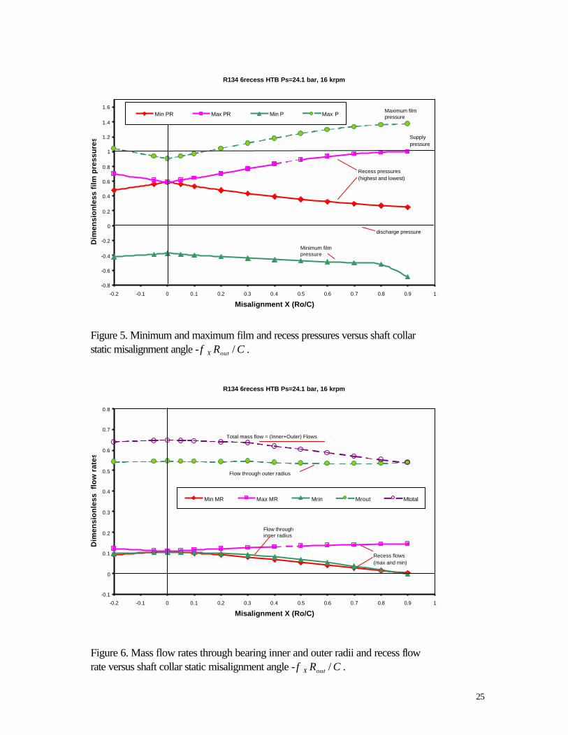
5 Minimum and maximum film and recess pressures versus shaft collar static misalignment angle (- CRoutX /φ ).
25
6 Mass flow rates through bearing inner and outer radii and recess flow rate versus shaft collar static misalignment angle (- CRoutX /φ ).
25
7 Axial load (FZ), drag torque (To) and restoring moments (MX, MY) versus shaft collar static misalignment angle (- CRoutX /φ ).
26
8 Synchronous (force) stiffness coefficients versus shaft collar static misalignment angle (- CRoutX /φ ).
27
9 Force damping coefficients versus shaft collar static misalignment angle (- CRoutX /φ ).
27
10 Synchronous moment stiffness coefficients versus shaft collar static misalignment angle (- CRoutX /φ ).
28
11 Moment damping coefficients versus shaft collar static misalignment angle (- CRoutX /φ ).
28

1
COMPUTATIONAL ANALYSIS OF MISALIGNED HYBRID THRUST BEARINGS FOR ADVANCED CRYOGENIC TURBO PUMPS INTRODUCTION Hybrid (combination hydrostatic and hydrodynamic) journal and thrust bearings and damping seal bearings are currently used as radial support elements in state of the art cryogenic turbo pumps. These compact - low count part turbo pumps operate sub critically at exceedingly high shaft speeds (180 krpm) with pressure differentials as large as 550 bars (8,000 psi). Externally pressurized fluid film bearings and seals enable to carry safely large thrust and lateral loads with virtually no DN life limit, little friction and wear, provide accuracy of positioning, and render large direct stiffness and damping force coefficients for control of critical speeds and attenuation of undesirable vibrations. These features even allow unshrouded impellers, thus significantly increasing turbo pump reliability. The development of analytical models and design tools and the testing of components address to the mandates of an "all-fluid-film- bearing" technology for advanced and less costly (per launching cost) turbo pumps. San Andrés (1990-1996) performed the thermohydrodynamic analyses and developed computer programs for prediction of the static and dynamic force response of radial fluid film bearings. The research addressed effectively the theoretical and practical issues related to the operation and dynamic performance of cryogenic fluid film bearings; namely high speeds and pressures, flow turbulence, fluid inertia, fluid compressibility, thermal effects, and two-phase flow phenomena. The computational predictions have been validated with test data from process fluid film bearings with mineral oils, water and air in regimes of operation ranging from laminar flow to turbulent flows, and including the transition zone to fully developed turbulence.
San Andrés (1998, 2000) advanced the original bulk-flow analysis of hybrid thrust bearings for cryogenic fluid applications. The model and computational program include the most important physical aspects paramount to the performance of turbulent flow fluid film bearings dominated by fluid inertia effects on the film lands and bearing recesses, and including a realistic thermo physical model and fluid properties. At high surface speeds, centrifugal forces could lead to sub ambient film pressures, induce lubricant cavitation or denude of fluid large areas of the bearing surface, thus significantly reducing the thrust bearing load capacity. Furthermore, large circumferential fluid speeds greatly affect the inertial pressure drop at the edges of the bearing recesses. The performance of thrust bearing for a refrigerant (dual use) application was evaluated at two operating speeds and pressure drops. The computed results, presented in dimensionless form, evidenced consistent trends in the bearing performance characteristics. As the applied axial load increases, the bearing operating clearance and flow rate decrease while the recess pressures increase. The axial stiffness coefficient shows a maximum for a certain intermediate load (recess pressure ratio) while the damping coefficient steadily increases. The predictions show at low recess pressures (i.e. low loads) fluid inflow through the bearing inner diameter and sub ambient pressures just

2
downstream of the bearing recess edges. These effects are solely due to centrifugal and Coriolis fluid inertia forces at sufficiently large surface speeds. The present analysis advances the original work to include the effects of static shaft misalignments and dynamic shaft angulations on the static and dynamic force and moment performance of hybrid thrust bearings. Mass flow conservation, momentum and transport bulk flow equations are presented and numerically solved for hybrid thrust bearings, pressurized face seals and hydrodynamic thrust bearings. A perturbation analysis of the flow equations renders first-order (linearized) flow equations for determination of the dynamic force and moment coefficients due to shaft axial motions and angulations about two orthogonal axes. The analysis renders nine stiffness, nine damping and nine inertia force/moment coefficients for routine engineering analysis and prediction using commercial rotordynamics computational programs. Formulae for the threshold speed of instability and whirl frequency ratio in aligned hybrid thrust bearings are advanced with important implications for the critical mass moment of inertia in compact rotors. The numerical method of solution implemented follows well-known CFD – control volume procedures for staggered meshes. The features of the computer program developed are also detailed. BULK FLOW ANALYSIS Figure 1 shows the geometry of a hybrid (hydrostatic/hydrodynamic) thrust bearing. The thrust bearing maybe composed of a single continuous (360°) pad with (Nrec) recesses distributed around the bearing area, or a number of pads (Npad) separated by radial grooves. Each pad contains one or more recesses. Figure 2 displays a runner (shaft) surface with angular static misalignment angles φX, φY about the lateral axes (X,Y), respectively. In general, the bearing film thickness is written as
θφθφθθ sinRcosR),R(HCh)t,,R(H XYpad* −+== (1) where C* is a characteristic clearance, and Hpad is the pad clearance including circumferential (δθ) and radial (δr) tapers [1, 2]. Consider the turbulent flow within the film lands of a hybrid (hydrostatic/hydrodynamic) thrust fluid film bearing. The bulk-flow equations of motion within the thin film lands and the perturbation analysis for description of the equilibrium flow (zeroth-order) and perturbed flow (first-order) due to small amplitude axial and angular motions of the shaft collar follow.

3
Ω shaft speed
Rininner radius
film land
Uθtangentialvelocity
θ
R
Routouter radius
Urradial
velocity
Ω
film land
orifice
hydrostaticrecess
H: film thicknessshaft (collar)
bearing
Figure 1. Geometry of a hydrostatic / hydrodynamic thrust bearing
Figure 2. Depiction of bearing with shaft angular misalignments
oxϕ
RRcos
-
X
θ
oyϕY
X
Z
oyϕ
c
Z
θϕ sinr ox−
XY-Plane XZ-Plane
YZ-Plane
Y
θϕ cosroy

4
The equations of mass, radial and circumferential momentum, and energy transport for the bulk-flow velocities, pressure and temperature on the bearing film lands are given in dimensionless form as [2,3]: continuity:
( ) ( ) ( )
0uh
r1
ruhr
r1h r =
∂∂
+∂
∂+
∂∂
θρρ
τρ
σ θ (2.a)
radial momentum:
( ) ( ) ( )rP
h- uh
uhr1uuh
r1
r uhr
r1
uh
Re rr2r
2rr
*p ∂∂
=+
−
∂∂
+∂
∂+
∂∂
κµ
ρθ
ρρτ
ρσ θ
θ (2.b)
circumferential momentum:
( ) ( ) ( )
θΛκκ
µ
ρθ
ρρτ
ρσ
θθ
θθθθ
∂∂
−=
−+
+
∂∂
+∂
∂+
∂∂
Prh
r21
uh
uuhr1uh
r1
r uuhr
r1
uh
Re
S
r
2r
*p
(2.c)
energy transport:
( ) ( ) ( ) ( )
( )
+
+++
∂∂
+
∂∂+
∂∂+
∂∂++
=+
+
∂∂
+∂
∂+
∂∂
θθθθ
θ
θ
ΛΛκµ
Λκµ
θΛ
θτσβ
θρρ
τρ
σ
u - r r h
ur 21
uu h
P h
21
P u r1
rP up T hTHTH
E
Re
T HH E
ReTuh
r1
rTuh
Th C
E
Re
4
1S
22r
rTSSBBc
*p
SBc
*prp
c
*p
(2.d)
Refer to the Nomenclature for a definition of all dimensionless variables. In the equations
above,*
*
URΩ
Λ = and *
*
URω
σ = are characteristic surface rotational speed and frequency
numbers, respectively; *
*
*
****P R
CCURe
=
µρ is a nominal Reynolds Number based on the

5
pressure induced flow, and
==
*
2***
*PC
ReReµωρ
σσ is the squeeze film Reynolds
number. *p*
2*
cCT
UE = is the Eckert heat transfer number, and ( )SB H,H are
dimensionless convection heat transfer coefficients. The ratio
c
*p
E
Rerefers to the effect
of heat convection relative to mechanical shear dissipation. The turbulent flow shear factors (κr=κθ, κS) are defined in terms of the friction factors (f) and Reynolds numbers (Re) relative to the stationary bearing (B) surface and shaft (S) rotating surface. The Benedict-Web-Rubin equation of state is used to obtain cryogenic liquid properties (ρ,µ,,Cp) [4]. In a hydrostatic bearing, the fluid at pressure (Ps) and temperature (Ts) is supplied through orifice restrictors into the bearing pockets or recesses. The continuity equation at a hydrostatic recess establishes a balance among the mass flow through the feed orifice (MR), the flow through the boundaries of the recess into the film lands (MΓ), and the accumulation of fluid mass within the recess volume, VR=[AR (H+HR)+Vsupply]. The conservation of mass flows at a bearing recess is given in dimensionless form as,
rec
i
i
iii N,....,1iR
TPiRR
RR ;TP
VV
MM =
∂∂
−∂∂
+∂
∂+=
τβ
τβ
τρσΓ (3.a)
where ( )[ ] 2/1iRiRoiRoiR P1M −= ρδ , and ∫ ⋅=
iB ii duhM ΓηρΓrr
(3.b)
and δRi as the orifice parameter. The energy transport balance within a bearing hydrostatic recess accounts for the mechanical energy dissipated by viscous shear, the heat-carry over (advection) from upstream conditions and the thermal mixing effects, i.e.
( )rec
R *
ii
i
i
N,...,1i
iRop
cRpsRP
RRp T
ReE
d.uhTCTMC)T(
VC=
∫
+−=
∂
∂
ΓΛΓηρ
τ
ρ rr (3.c)
where R)T,P( are the averaged pressure and temperature within the recess, and
RTP ),,( ββρ are the dimensionless fluid density, fluid compressibility and thermal expansion coefficients, respectively. The circumferential and radial pressure rises within the hydrostatic recesses are given, respectively, by
6
( )recN,...,1iR
S2R
RRRRRe 2
ru
hh2
rPP
=
−
−+
+=Λ
κκΘ
µ θθ (4.a)
( )( )
recN,...,1i
2R
2R*p
Rrr2
R
Rr2dynRR )sln(
UhhRe
ruk2
us
u11sPPP
=
+−
+−+=
θθ ρ
µ (4.b)
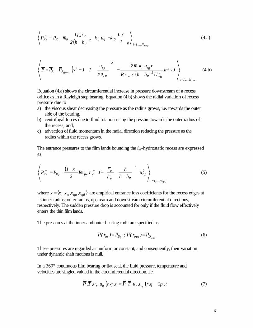
Equation (4.a) shows the circumferential increase in pressure downstream of a recess orifice as in a Rayleigh step bearing. Equation (4.b) shows the radial variation of recess pressure due to a) the viscous shear decreasing the pressure as the radius grows, i.e. towards the outer
side of the bearing, b) centrifugal forces due to fluid rotation rising the pressure towards the outer radius of
the recess; and, c) advection of fluid momentum in the radial direction reducing the pressure as the
radius within the recess grows. The entrance pressures to the film lands bounding the ith-hydrostatic recess are expressed as,
( )
recN,...,1i
2,r
2
Re
ee*peReR u
hhh
1Re2
1PP
=
+
−−+−
+
−
++= θ
ρ
ρρ
ξ (5)
where duoi ,,, θθ ξξξξξ = are empirical entrance loss coefficients for the recess edges at its inner radius, outer radius, upstream and downstream circumferential directions, respectively. The sudden pressure drop is accounted for only if the fluid flow effectively enters the thin film lands. The pressures at the inner and outer bearing radii are specified as,
outDoutinDin P)r(P;P)r(P == (6)
These pressures are regarded as uniform or constant, and consequently, their variation under dynamic shaft motions is null. In a 360° continuous film bearing or flat seal, the fluid pressure, temperature and velocities are singled valued in the circumferential direction, i.e.
( ) ( )t,2,ru,u,T,Pt,,ru,u,T,P rr πθθ θθ += (7)

7
In a bearing pad, on the other hand, the pressures at the leading and trailing edges are specified radial function of the inner and outer radii pressures )P,P(
outDinD .
Note that the momentum and energy flow equations applicable to the film lands are of hyperbolic character, and consequently, no exit conditions are required for the discharge temperature and fluid velocities at the bearing inner and outer radii. The balance of flow leaving the bearing recesses and entering the film lands provides the (inner) boundary conditions for the velocity fields within the thin film flow region, see equations (3). Perturbation analysis of the flow field A perturbation analysis of the flow field for small amplitude axial and angular motions of the shaft collar about an equilibrium position follows. The analytical procedure renders sets of zeroth- and first-order flow equations for evaluation of the bearing static load capacity, drag torque, bearing and recess flow rates, and dynamic force and moment coefficients. Consider the thrust collar to undergo small amplitude axial (∆Z) and angular rotations (∆φX, ∆φY) at a frequency (ω) about an equilibrium position (h0). The film thickness is written as [5],
[ ]θφ∆φθφ∆φ∆
θθ ωωω sinecoserCR
eC
z),r(h)t,,r(h ti
XXoti
YYo*
*ti
*opad +−+
+
+= (8)
with i=(-1)1/2.
0padh and 00
, YX φφ correspond to the pad film thickness and shaft static misalignment angles at the equilibrium condition1. Note that only the real part of the expression above is of importance in the analysis. Using linear superposition, the equilibrium and perturbed films represented by zeroth- and first-order variables give,
τφφ
∆τθ i
*
*
*
*Z
*o eh
CR
hCR
hC
zh),,r(h
XY
+
+
+= (9.a)
where τ=ω t,
θφθφθθ sinrCR
cosrCR
),r(h),r(h Xo*
*Yo
*
*opado
−
+= (9.b)
and θθ φφ sinrh;cosrh;1h
XYZ −=== (9.c)
1 This equilibrium condition arises from the balance of the fluid film bearing reaction thrust (axial) force and restoring moments with the externally load and misalignment moments applied on the bearing.

8
Note that YXZ
iehid
hd
φφα
τα
α
τ ,,=
= . The flow pressure, temperature, bulk-flow velocities
and shear factors are also expressed as the superposition of zeroth-order 0ψ and first-order
YXZ φφααψ ,,= flow fields describing the equilibrium and the perturbed fields,
respectively, i.e.,
τφφ ψφψφψψψ i
XYZ eCR
CR
Cz
XY
∆
+∆
+
∆+=
*
*
*
*
*0 (10)
where .,,,,,,,,, etcTPuu Srr κκκµρψ θθ= . Substitution of definitions (9) and (10) into the thin film land equations (2) leads to the zeroth- and first-order governing equations for the fluid bulk-flow. Zeroth-order bulk-flow equations on the film lands continuity:
( ) ( )
0uh
r1
ruhr
r1 0000r00 =
∂∂
+∂
∂θ
ρρ θ (11.a)
radial momentum:
( ) ( )rP
h- uh
uhuuh
r
uhr
r1
Re 00r00r
0
02000
0r0002r000
*p ∂∂
=+
−
∂∂
+∂
∂κ
µρ
θρρ
θθ (11.b)
circumferential momentum:
( ) ( )
θΛκκ
µ
ρθ
ρρ
θθ
θθθ
∂∂
=
−+
+
∂∂
+∂
∂
000S00
0
0
00r00
20000r000
*p
Prh
- r21
uh
uuhuh
r
uuhr
r1
Re
(11.c)
energy transport:
( ) ( ) ( )
( )
+
+++
∂∂
+
∂∂
+∂
∂++
=+
+
∂∂
+∂
∂
0S00
00
20
2r00
0
000
00
00r000T0S0S0BB0
c
*p
00SB0c
*p000000r00p0
c
*p
u - r r h
ur 21
uu h
P h
21
P u
r1
rP
u T hTHTH E
Re
T HH E
ReTuh
r1
rTuh
C E
Re
41
θθθθ
θ
θ
ΛΛκµ
Λκµ
θΛ
θβ
θρρ
(11.d)

9
First-order bulk-flow equations on the film lands With αh : θθ φφ sinrh;cosrh;1h
XYZ −=== for dynamic shaft axial motions and angulations about the (Y) and (X) axis, respectively. the perturbed flow equations are: continuity:
( )
( ) 0
uhuhuh
r1
r
uhuhuhr
r1
hhi
0000r00r0r0
00
0000 =∂
++∂+
∂
++∂
++
θ
ρρρρρρ
ρρσ
ααα θθθααα
αα
(12.a)
radial momentum:
( ) ( )
2
1
Re
0
00
00
0000
0000*
r 0
−
∂
∂+
∂
∂+
+∂
∂+
∂
∂
+++++=∂∂
−
αα
αα
ααα
θθ
θ
ααθθα
θρσρ
θ
ρρ
γγγγγ
uuu
hur
uirh
uuh
r
uuhr
r
TPuuhr
Ph
rr
r
rrrp
rTrPrrrrh
α=Z,φY,φX (12.b)
circumferential momentum:
( ) ( )
+
∂
∂+
∂
∂++
+∂
∂+
∂
∂
+++++=∂∂
−
αα
αα
ααα
θθ
θθ
θθθ
αθαθθθθθθα
ρθ
σρ
θ
ρρ
γγγγγθ
rr
rp
Tprrh
uur
urhu
uurih
uuh
r
uuhr
r
TPuuhP
rh
0
00
0
00
0000
0000*
0
1
Re α=Z,φY,φX (12.c)
energy transport:
( ) ( )
( )
∂
∂+
∂∂
=
∂∂
−⋅−+++
+
++
∂
∂+
∂
∂
θβ
θΛ
βσγγγγ
ρσγθ
ρρ
αθα
ααθθα
ααθα
αα
Pr
u
rP
uTh
Ph
2PThi uuh
TCE
Rehi
Tuh
r1
r
TuhC
E
Re
0
0
0
0
00
0
0r00T
`000TTPTrTrTh
pc
*p00TT
00r00P
c
*p
(12.d)
α=Z,φY,φX

10
San Andrés [2] lists the formulae for the first-order wall shear stress coefficients (γ‘s).
Zeroth- and first-order flow equations at a bearing recess Perturbation of the recess mass flow and energy transport equations proceeds in the same manner. For the recess flows the linear combination of equilibrium and dynamic fields gives
τφφ φ∆φ∆
∆ iRX
*
*RY
*
*ZR
*0RR eM
CR
MCR
MC
ZMM
XY
+
+
+= (13)
The zeroth- and first-order equations for mass flow conservation at each recess are respectively,
( )[ ] ∫ =⋅==−=i reci0
2/1
i0i0i00 N,...,1ii000RRoRiR ,duhMP1M ΓΓ Γηρρδrr
, (14)
and
( )rec
ii00iii N,...,1iR
TRiiRRR
PR TChAiMPC
=++=−
ααα αΓ ρσ α=Z,φY,φX (15)
where
[ ] ( )
( ) recN,...,1i
i0R0R
0RRT
TiR
i0RRP0R0RRP
0R
0RPiR
;Vi2
MC
Vi)P1(1)P1(2
MC
=
−=
+−−−
=
ρσβ
ρβσβ
(16.a)
with ( )∫ =⋅++=
i recN,..,1ii000000i;duhuhuhM
Γ αααΓ Γηρρρα
rrrr α=Z,φY,φX (16.b)
as the first-order mass flow rates through the recess boundaries into the film lands. The first-order energy transport equation at the recess and the pressure rise/drop equations at the recess edges are omitted for brevity. Fluid film axial force and restoring moments Integration of the pressure field on the thrust collar surface (shaft) renders the axial force (FZ) reacting to an applied external load (WZ) and the restoring moments (MY, MX), i.e.

11
∫∫
∫
−=
−−=
−=−=
B
B
B
A
aY
A
aX
A
aZZ
ddRRcosR)PP(M
ddRRsinR)PP(M
ddRR)PP(WF
θθ
θθ
θ
(17)
Recall that the pressure field is the superposition of zeroth- and first-order fields
τφφ φ∆φ∆
∆ iX
*
*Y
*
*z
*0
as
a ePCR
PCR
PC
ZP
PPPP
PXY
+
+
+=
−−
= (18)
due to the axial and angular changes in film thickness defined by
τφφ
∆τθ i
*
*
*
*Z
*o eh
CR
hCR
hC
Zh),,r(h
XY
+
+
+= with θθ φφ sin;cos;1 rhrhh
XYZ −===
Substitution of the pressure field, equation (18), into the force and moment equations (17) gives,
( )
( )
( )∫
∫
∫
∆
+∆
+
∆+∆+=
∆
+∆
+
∆+∆−=
∆
+∆
+
∆+∆=
B
XY
B
XY
B
XY
A
iXYZsaY
A
iXYZsaX
A
iXYZsaZ
ddrrePCR
PCR
PC
ZPRPM
ddrrePCR
PCR
PC
ZPRPM
ddrrePCR
PCR
PC
ZPRPF
θθφφ
θθφφ
θφφ
τφφ
τφφ
τφφ
cos
sin
2
*
*
*
*
*0
3*
2
*
*
*
*
*0
3*
*
*
*
*
*0
2*
(19)
where ∆Psa=(Ps-Pa) . Fluid film dynamic axial force and moment coefficients The bearing thrust force (FZ) and restoring moments (MX, MY) are also expressed as the superposition of equilibrium and dynamic forces and moments, i.e.
ti
X
Y
Z
Z
ZZZZ
X
Y
Z
X
Y
Z
eZ
ZZZZZZZZZ
MMF
MMF
XXYXX
XYYYY
XYω
φφφφφ
φφφφφ
φφ
φφ
∆∆∆
−
=
0
0
0
(20)

12
where the
YXZZ
φφβαβα ,,, =correspond to bearing impedances arising from the dynamic
shaft motions. The dynamic stiffness (static stiffness and inertia) and damping coefficients are obtained from the real and imaginary parts of the impedance coefficients, i.e.
XY2 ,,Z,;ZCiMK φφβαωω αβαβαβαβ ==+− (21)
With the definitions forwarded, the bearing equilibrium forces and moments are given by
( )
( )
( )∫∫
∫
+=
−=
=
θθ∆
θθ∆
θ∆
ddrrcosrPRPM
ddrrsinrPRPM
ddrrPRPF
03*saY
A
03
*sa0X
A
02
*saZ
0
B
B
0
(22)
and the dynamic bearing impedances are determined from
∫
∫∫
∫
∫∫
∫
∫∫
−=
−=
−=
+=
+=
+=
−=
−=
−=
B
XXY
B
XYY
B
Y
B
XXX
B
YYX
B
X
B
XX
B
YY
B
A
2
*
4*sa
A
23*
4*sa
A
2Z
*
3*sa
Z
A
2
*
4*sa
A
2
*
4*sa
A
2Z
*
3*sa
Z
A*
3*sa
Z
A*
3*sa
Z
A
Z*
2*sa
ZZ
ddrcosrPC
RPZ
ddrcosrPC
RPZddrcosrP
C
RPZ
ddrsinrPC
RPZ
ddrsinrPC
RPZddrsinrP
C
RPZ
ddrrPC
RPZ
ddrrPC
RPZddrrP
CRP
Z
,
,
,,
θθ∆
θθ∆
θθ∆
θθ∆
θθ∆
θθ∆
θ∆
θ∆
θ∆
φφφ
φφφφ
φφφ
φφφφ
φφ
φφ
(23)

13
Force and moment coefficients at the statically aligned condition At the statically aligned shaft and bearing condition, 0
00== YX φφ , the force coefficients
due to dynamic angulations and the moment coefficients due to axial displacements are null, i.e.
MCKZZZZZ YZZZ XXYX,,;00 ====== φφφφ (24)
A simple dynamic analysis for the stability of a rotating inertia determines the equivalent angular stiffness and whirl frequency ratio for shaft angulations as,
( )( )( )
YXXYYYXX
YXXYYYXX
YYXX
YXXYXYYXXXYYYYXX
CCCC
KKKKKKWFR
CCCKCKCKCK
K
eqeqn
eq
φφφφφφφφ
φφφφφφφφ
φφφφ
φφφφφφφφφφφφφφφφ
ω−Ω
−−−=
Ω=
+−−+
=
2
22
(25)
The equations above may be used to determine the threshold speed of instability for shaft angular motions in a simple system. Furthermore, at the aligned shaft condition, the following conditions also follow due to the rotational symmetry of the thrust bearing,
MCKZZZZZYXXYYYXX
,,;; =−== φφφφφφφφ (26) That is, the direct moment coefficients are symmetric and the cross-coefficients are anti-symmetric (due to the characteristic hydrodynamic effect). In this case, the matrix of dynamic impedances reduces to
[ ]
−=
XXYX
YXXX
ZZZZ
ZZ
ZZ
φφφφ
φφφφ
00
00 (27)
demonstrating the uncoupling between axial and angular shaft motions. The equivalent moment coefficient and whirl frequency ratio then reduce to
XX
YX
XX
YX
YXXX C
KWFR
C
CKKK eq
φφ
φφ
φφ
φφφφφφ Ω
=+= ; (28)

14
The solution procedure Equations (11) and (14) describing the equilibrium flow field are solved using a control-volume numerical procedure. San Andrés details the discretization method and algorithm used in the computational analysis [2, 6]. The (discrete) first order flow fields defined by equations (12) and (15) are found once the zeroth-order fields are obtained. Bearing reaction forces and moments as well as dynamic force/moment coefficients follow from numerical integration of the flow fields on the bearing collar surface. The interested reader should consult the works of Launder and Leschizer [7] and Van Dormaal and Raithby [8] for complete descriptions on the CFD procedure, including orders of accuracy and convergence. THE COMPUTER PROGRAM HYDROTHRUSTM The HYDROTHRUSTM Fortran 90 computer program is an extension of the earlier HYDROTHRUST first released in 1998. Both programs run as console applications in a personal computer under the MS Windows operating system. The software includes a windows based help file (hthrust.help) and several examples featuring the options and capabilities of the program. HYDROTHRUSTM calculates the static and dynamic force performance characteristics for the following bearing configurations: 1. hydrostatic / hydrodynamic thrust bearings with orifice compensation, 2. annular face seal with a pressure drop from inner diameter to outer diameter, 3. plain hydrodynamic thrust bearings. Orifice injection is specified as axial or angled respect to the shaft rotational speed direction. The feed hole may be located anywhere within the recess, i.e. upstream or downstream of the middle plane. HYDROTHRUSTM includes the following thermal models: - adiabatic surfaces, i.e. insulated shaft and bearing surfaces. - isothermal shaft at specified temperature and insulated (adiabatic) bearing. - isothermal bearing at specified temperature and insulated (adiabatic) shaft. - isothermal shaft and bearing surfaces. - isothermal shaft and radial heat flow through bearing (stator). - adiabatic shaft and radial heat flow through bearing (stator). HYDROTHRUSTM calculates numerical predictions of: • bearing flow rate or seal leakage, • friction torque, power dissipation and temperature rise, • load capacity if bearing minimum film clearance is given, or bearing film clearance if
the external thrust load is given, • restoring moments about two axes,

15
• three axial force stiffness, damping and inertia force coefficients due to collar displacements ( Z∆ ), and two shaft rotations ( YX φφ ∆∆ , ),
• three x two (=6) moment stiffness, damping and inertia force coefficients due to collar displacements ( Z∆ ), and two shaft rotations ( YX φφ ∆∆ , ).
Thus, the matrix of dynamic force coefficients comprises a total of 27 values corresponding to nine stiffness, nine damping and nine inertia force/moment coefficients. The program interfaces with the NIST database to calculate the thermophysical properties of the following (single phase) cryogenic fluids:
(1) parahydrogen, (2) oxygen, (3) nitrogen, (4) methane. Other fluids incorporated in the program are: (5) water, (6) oil, (7) air, (12) barotropic fluid. The help file hthrust.help gives a detailed description of the program operation and input/output calculation options. PREDICTIONS AND DISCUSSION The analysis and computational program are applicable to a wide range of thrust bearing applications including operation at low speeds and feed pressures with viscous mineral oils (laminar flow bearings), and high speed hydrostatic / hydrodynamic thrust bearings for implementation in modern compact cryogenic liquid turbo pumps and state of the art turbomachinery using process fluid lubricants. To date, however, experimental results for these novel applications are not available in the open literature. Table 1 presents the geometry and operating conditions of a six recess hydrostatic thrust bearing with R134a refrigerant for a commercial compressor application. San Andrés [2, 3] presents extensive predictions for a range of thrust loads at two operating speeds, 10 and 16 krpm, and pressure drops of 5.17 and 10.34 bars (75 and 150 psi), respectively. The operating film clearances ranged from 12.7 to 101.6 µm. The computed predictions show the paramount effect of fluid inertia (on film lands and recess edges) on the performance characteristics of the thrust hybrid bearing. The discussion concentrates on the effects of a static shaft misalignment ( )Xφ on the performance characteristics of the hybrid thrust bearing operating with a nominal clearance (C) of 0.508 mm. All calculations were performed with the full fluid inertia model, i.e. including fluid inertia effects at the film lands and recesses (area and edges interfacing with the film lands). For reference in the discussion, Table 2 introduces the definitions for the dimensionless bearing performance characteristics.

16
Table 1. Hydrostatic thrust bearing for R134a compressor application Axial injection at mid plane of a recess.
Geometry, Nrec=6 SI dimensions English dimensions Inner diameter Din 89.13 mm 3.51 inch Outer diameter Dout 126.8 mm 4.99 inch Recess diameter DR 108.6 mm 4.28 inch Recess radial length LR 11.68 mm 0.46 inch Recess arc length
RΘ 24 o Recess depth HR 0.508 mm 0.020 inch Film clearance (nominal) C 0.051 mm 0.002 inch Recess/Bearing area ratio 0.25 Orifice diameter do 1.70 mm 0.067 inch Empirical parameters Orifice discharge coefficient
Cd 0.80
Entrance loss coefficients,
0.0, 0.0, 0.0, -0.5 duoi rr θθ ξξξξ ,,,
Inlet swirl coefficient α 0.50 Bearing and collar relative surface roughness = 0.45%
Operating conditions SI units English units Speed Ω 1,675 rad/s 16,000 rpm Supply temperature Ts 311 o K 560 o R (100o F) Supply pressure, Ps 24.10 bar 350 psia Exit pressure, PDin=PDout Pa 13.80 bar 200 psia Saturation pressure Psat 9.63 bar 139 psia Fluid properties R134a refrigerant Density aρ 1210 kg/m3 75.54 lb/ft3
Viscosity aµ 0.000198 Pa.s 0.0288
microReyns Fluid bulk modulus ( )pβ/1 1,820 bar 26,667 psi Circumferential Reynolds number Re 33,000

17
Table 2. Definitions for dimensionless bearing performance parameters, force and moment coefficients.
Symbol Dimensionless parameter Pressure
P
as
a
PPPP
p−−
=
Mass flow rate
M
( )[ ] 2/12 assodrec PPACN
MM
−=
ρ
Load
FZ ( )asBZ
Z PPAFFF
F −== **
;
Torque
OT ;
oT
OO T
TT = [ ]
CRA
Re4.0024.01T2outBs65.0
c2
oTΩµ
+=
Moments
YX MM ,
out
YY
out
XX RF
MM
RFM
M**
, ==
Axial force stiffness coefficients
XY ZZZZ KKK φφ ,,
out
ZZ
out
ZZ
ZZZZ RF
CKK
RF
CKK
FCK
K X
X
Y
Y***
,, φφ
φφ ===
Axial force damping coefficients
XY ZZZZ CCC φφ ,,
out
ZZ
out
ZZ
ZZZZ RF
CCC
RF
CCC
FCC
C X
X
Y
Y***
,,Ω
=Ω
=Ω
= φφ
φφ
Axial force inertia coefficients
XY ZZZZ KKM φφ ,,
out
ZZ
out
ZZ
ZZZZ RF
CMM
RFCM
MFCM
M X
X
Y
Y*
2
*
2
*
2
,,Ω
=Ω
=Ω
= φφ
φφ
Moment stiffness coefficients
XYYYYKKK Z φφφφφ ,,
XXXYXKKK Z φφφφφ ,, 2
*2
**
,,outoutout
ZZ RF
CKK
RF
CKK
RF
CKK XY
XY
YY
YY
Y
Y
φφφφ
φφφφ
φφ ===
Moment damping coefficients
XYYYYCCC Z φφφφφ ,,
XXXYXCCC Z φφφφφ ,, 2
*2
**
,,outoutout
ZZ RF
CCC
RF
CCC
RF
CCC XY
XY
YY
YY
Y
Y
Ω=
Ω=
Ω= φφ
φφφφ
φφφ
φ
Moment inertia coefficients
XYYYYMMM Z φφφφφ ,,
XXXYXMMM Z φφφφφ ,, 2
*
2
2*
2
*
2
,,outoutout
ZZ RF
CMM
RFCM
MRFCM
M XY
XY
YY
YY
Y
Y
Ω=
Ω=
Ω= φφ
φφφφ
φφφ
φ

18
Force and moment coefficients for the aligned hybrid thrust bearing Table 3 details the predicted values of the bearing characteristics at the nominal clearance position, C=0.051 mm, and without shaft misalignment. Note that for the aligned condition, the restoring moments are null, i.e. MX=MY=0.
Table 3. Bearing performance parameters at nominal operating clearance and aligned shaft collar.
Symbol Dimensional value Recess, minimum and maximum film pressures
PR, Pmin, Pmax 19.81, 9.95, 23.175 bars
Recess mass flow rate, mass flow rate through inner and outer radii
MR, MRin, MRout 0.0588, 0.0567, 0.297 kg/s
Axial load and torque FZ, To 1374 N, 3.57 Nm Restoring Moments
YX MM , 0, 0 Nm Axial force stiffness coefficients
XY ZZZZ KKK φφ ,,
41.3 MN/m, 0 N/rad, 0 N/rad
Axial force damping coefficients XY ZZZZ CCC φφ ,, 29.4 kN s/m, 0 N s/rad, 0 N s/rad
Axial force inertia coefficients XY ZZZZ KKM φφ ,,
2. 36 Ns2/m, 0 N s2/rad, 0 N s2/rad
Moment stiffness coefficients
XYYX
YYXX
KK
KK
φφφφ
φφφφ
−=
=
64.2 kN m/rad, 36.1 kN m/rad
Moment damping coefficients
XYYX
YYXX
CC
CC
φφφφ
φφφφ
−=
=
43.65 N m s/rad 6.25 N m s/rad
Moment inertia coefficients
XYYX
YYXX
MM
MM
φφφφ
φφφφ
−=
=
3.3010-3 N m s2/rad -0.19 10-3 N m s2/rad
Other cross-force and moment coefficients 0 San Andrés [2, 3] discusses the bearing performance for two operating speeds and increasing axial loads. Figure 3 reproduces some of the calculated axial load performance parameters for the statically aligned hybrid thrust bearing ( 0== YX φφ ). Note that as the axial load increases, the recess pressure )( RP increases towards the supply value and the operating (axial) clearance decreases rapidly. For the smallest load the maximum or largest clearance equals101.6microns. The dynamic force damping coefficient (CZZ) for axial motions remains more or less uniform for the range of small to moderate loads, and increases rapidly for heavily loaded conditions due to enhanced hydrodynamic effects. The static (KZZ) and synchronous (KZZ-MZZ) axial stiffness coefficients show a typical behavior with an optimum value for moderate loads at a recess pressure ratio )( RP ~ 0.6, as expected from a turbulent flow hydrostatic bearing.

19
Recall that at the statically aligned bearing condition, ;00 ===== YZZZ XXYX
ZZZZ φφφφ
and ;;YXXYYYXX
ZZZZ φφφφφφφφ −== thus, the equivalent moment stiffness coefficient and
whirl frequency ratio reduce toXX
YX
XX
YX
YXXX C
KWFR
C
CKKK eq
φφ
φφ
φφ
φφφφφφ Ω
=+= ; .
Figure 4 depicts the moment coefficients for increasing axial loads. The static and (synchronous) dynamic direct coefficients ( )
XXXXXXMKK φφφφφφ −, show a similar
behavior as the axial force coefficients, i.e. render low values for small and large recess pressures and an optimum (maximum) value at about the same recess pressure for the axial force stiffness. On the other hand, the direct moment/angle damping ( )
YYXXCC φφφφ =
and cross-stiffness ( )YXXY
KK φφφφ −= coefficients increase rapidly with the applied load, thus denoting the large influence of hydrodynamic effects as the operating clearance decreases. The whirl frequency ratio (WFR) is approximately 0.50 for all operating conditions, thus showing hybrid thrust bearings undergoing angular shaft motions have the same inherent stability limit as hydrodynamic thrust bearings and face seals. Effect of shaft static misalignment on thrust bearing performance The following figures depict the effect of the shaft collar static misalignment angle ( )Xφ on the performance characteristics of the hybrid thrust bearing operating with a nominal clearance of 0.51 mm [ )( RP ~0.6]. Recall that operation at this condition shows near optimum (direct) axial force and moment direct stiffness coefficients. The calculations were conducted for misalignment angles ( )Xφ as large as 723 micro radians, which translate into a minimum film thickness as low as 10% of the nominal clearance. Figures 5 through 7 show the predicted static performance characteristics of the hybrid thrust bearing. Minimum and maximum film pressures and recess pressures increase (nearly) linearly as the misalignment angle increases. The largest film and recess pressures are located on the side of the minimum film thickness. The maximum film pressure is already larger than the supply pressure for relatively small misalignment angles and denotes the dominance of centrifugal hydrodynamic flow effects as noted earlier in [2]. The minimum film pressures are lower than the bearing discharge pressure due to fluid inertia effects as also discussed then2. Figure 6 depicts the dimensionless mass flow rates through the inner and outer radii of the bearing versus the misalignment angle. Again, due to centrifugal fluid inertia effects, the flow rate leaving the bearing through the inner radius decreases as the misalignment
2 The dimensionless pressure corresponding to the refrigerant saturation pressure equals –0.405. Thus, the predictions indicate zones of fluid cavitation (vaporization), in particular at the downstream side of a recess in the circumferential direction.

20
angle increases (minimum film thickness decreases). There is approximately a 20% reduction in flow rate (M=MRout+MRin) from the nominal condition to that with the largest misalignment angle. Figure 7 shows the predicted axial force ( )ZF , drag torque ( )oT and restoring moments
( )YX MM , versus the misalignment angle ( )Xφ . The axial force and drag torque remain relatively insensitive to the degree of misalignment while the restoring moments increase rapidly. The rate of growth of the hydrostatic reaction moment ( )XM appears to be linear with the misalignment angle, while the cross-moment ( )YM due to hydrodynamic effects is of importance at large misalignment angles. Figures 8 and 9 depict the dimensionless force stiffness and damping coefficients due to shaft axial displacements and angulations, respectively. As the misalignment angle ( )Xφ increases, the axial force stiffness and damping coefficients( )ZZZZ CK , due to shaft axial displacements are larger (though relatively invariant) than the force coefficients ( )
XX ZZ CK φφ , and ( )YY ZZ CK φφ , due to shaft angulations. However, for large misalignment
angles the cross-coefficients ( )XY ZZ CK φφ , due to hydrodynamic effects become important.
Figures 10 and 11 show the dimensionless moment stiffness and damping coefficients due to shaft angulations and axial displacements, respectively. The direct moment-angle coefficients are significant for an aligned shaft condition while the cross-moment coefficients are negligible. Note that the symmetry (anti-symmetry) relations hold at the aligned condition. The direct moment stiffness coefficients ( )
YYXXKK φφφφ , remain
relatively constant even for large misalignment angles, while the cross-stiffnesses ( )
XYYXKK φφφφ −, are smaller and increase rapidly due to the hydrodynamic shear flow
effect. The direct moment damping coefficients ( )YYXX
CC φφφφ , , always larger than the
cross-damping coefficients ( )XYYX
CC φφφφ −, , increase rapidly as the misalignment angle grows since the local film thickness is smaller. Note also that the hydrodynamic moment stiffness ( )ZY
Kφ− and damping ( )ZXCφ coefficients due to shaft axial displacements
increase rapidly for large misalignment angles.
The predicted whirl frequency ratio (WFR=Ω
nω) for a shaft collar undergoing dynamic
angulations remains uniform at approximately 0.50 for most misalignment angles. The equivalent moment stiffness ( )eqK , here mainly determined by the hydrostatic stiffnesses
( )YYXX
KK φφφφ ~ , provides a measure of the largest mass moment of inertia for safe
operation of the rotating system, i.e. 2n
eqKI
ω= without the likeliness of a hydrodynamic
instability.

21
The predictions presented correspond to a bearing with axial injection at the mid plane of a recess. Calculations were also performed for hydrostatic feed with a tangential feed injection (90 degrees) opposite to the shaft rotational speed and at different circumferential locations upstream and downstream of a recess. These predictions were conducted to determine if the whirl frequency ratio would decrease so as to render a more robust bearing free of hydrodynamic instability. Table 4 below shows the predicted results for the axial force, torque, force and moment coefficients for the bearing aligned condition at the nominal operating condition (C=0.051 mm).
Table 4. Predictions for aligned bearing with angled hydrostatic feed injection. Feed angle
Position FZ To KZZ CZZ XX
Kφφ
YX
Kφφ
XX
Cφφ
YX
Cφφ
Keq WFR
degrees kN Nm MN/m KNs/m KNm/rad KNm/rad Nm.s/rad Nm.s/rad KNm/rad 0 0.5 1.37 3.56 41.3 29.4 64.1 36.1 43.6 6.25 69.6 0.50 90 0.1 1.41 3.50 45.2 30.8 70.8 35.6 45.7 5.88 75.3 0.46 90 0.5 1.39 3.34 40.7 29.9 64.2 32.6 43.4 5.42 68.3 0.44 90 0.9 1.45 3.23 37.3 27.7 59.4 29.7 41.2 4.93 62.8 0.43
Angle: 0 = axial feed, +90 degrees = tangential against shaft rotation, -90 degrees= tangential parallel to shaft rotation Position: 0.5 = middle of recess, 0.0 = upstream edge of recess, 1.0 = downstream edge of recess.
The predictions show that angled injection reduces slightly the whirl frequency ratio but not significantly to free the bearing from its limited stability limit. Note that this bearing application has large surface speeds with a nominal circumferential flow Reynolds number approximately equal to33,000; thus then the limited advantage of angled injection. Similar results (theoretical and experimental) have been obtained for radial hydrostatic bearings [9]. Nonetheless note that a hybrid bearing with a tangential injection orifice location well upstream within the recess (position 0.1) shows a significant increase for its equivalent angular stiffness (Keq), thus effectively increasing the critical mass moment of inertia of the rotating system. On the other hand, tangential feed injection located well downstream of the recess (position 0.9) shows a significant reduction in the cross-coupled stiffness coefficient
YXK
φφ; thus rendering the lowest whirl
ratio but also the lowest equivalent angular stiffness. The predictions also show that the axial load and axial force displacement coefficients (KZZ , CZZ ) are not greatly affected by the angled feed injection.

22
CONCLUSIONS A bulk-flow analysis and computer program for prediction of the static load performance and dynamic force and moment coefficients of angled injection, orifice-compensated hydrostatic / hydrodynamic thrust bearings have been completed. Advanced cryogenic fluid turbopumps are very compact, operate at extremely high shaft speeds, and require of hybrid (hydrostatic / hydrodynamic) radial and thrust fluid film bearings for accurate rotor positioning and control of critical speeds. The analysis accounts for the bulk-flow mass, momentum and thermal energy transport, includes flow turbulence and fluid inertia (advection and centrifugal) effects on film lands and recesses, and incorporates cryogenic fluid properties using a NIST data base. The computer program predicts the flow rate, load capacity, restoring moments, power loss and 27 dynamic force coefficients for rigid surface, tapered land hybrid thrust bearings. Predictions on the effects of shaft collar misalignment on the static and dynamic force and moment performance of a refrigerant R134a hybrid thrust bearing are presented. The The axial force stiffness coefficient and the direct moment/angle stiffness coefficients show an optimum value for a certain load (recess pressure ratio) while the damping coefficient steadily increases with the applied load. As the misalignment angle increases, both moment and force coefficients due to shaft axial displacements and angulations also increase. The most important result is, however, the prediction of a whirl frequency ratio equal to 0.50 for most operating conditions. That is, thrust hybrid bearings offer the same limited stability characteristics as hydrodynamic bearings thrust when undergoing self-excited shaft angular motions. The research conducted concludes a multiple year effort funded by NASA Centers for the development of sound computational tools able to predict reliably the performance of externally pressurized bearings needed for their current state of the art turbo pump technology.
23
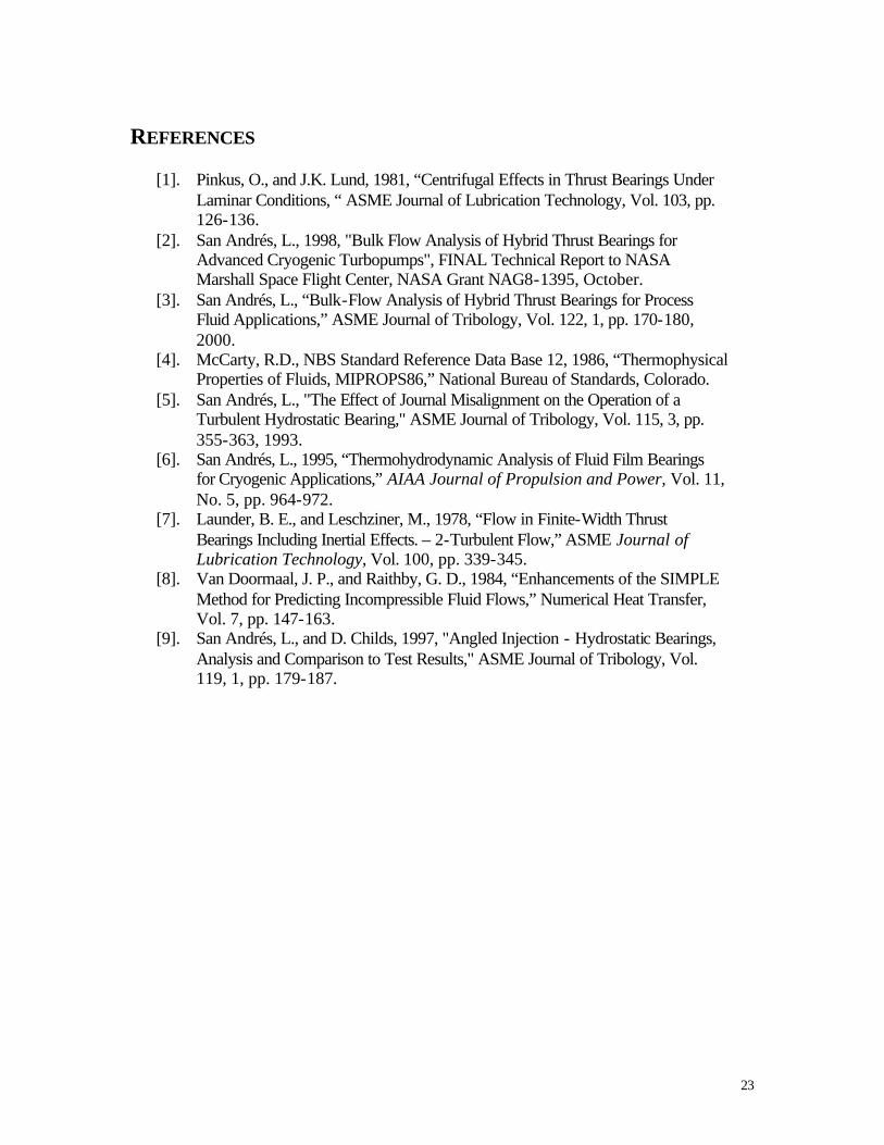
REFERENCES
[1]. Pinkus, O., and J.K. Lund, 1981, “Centrifugal Effects in Thrust Bearings Under Laminar Conditions, “ ASME Journal of Lubrication Technology, Vol. 103, pp. 126-136.
[2]. San Andrés, L., 1998, "Bulk Flow Analysis of Hybrid Thrust Bearings for Advanced Cryogenic Turbopumps", FINAL Technical Report to NASA Marshall Space Flight Center, NASA Grant NAG8-1395, October.
[3]. San Andrés, L., “Bulk-Flow Analysis of Hybrid Thrust Bearings for Process Fluid Applications,” ASME Journal of Tribology, Vol. 122, 1, pp. 170-180, 2000.
[4]. McCarty, R.D., NBS Standard Reference Data Base 12, 1986, “Thermophysical Properties of Fluids, MIPROPS86,” National Bureau of Standards, Colorado.
[5]. San Andrés, L., "The Effect of Journal Misalignment on the Operation of a Turbulent Hydrostatic Bearing," ASME Journal of Tribology, Vol. 115, 3, pp. 355-363, 1993.
[6]. San Andrés, L., 1995, “Thermohydrodynamic Analysis of Fluid Film Bearings for Cryogenic Applications,” AIAA Journal of Propulsion and Power, Vol. 11, No. 5, pp. 964-972.
[7]. Launder, B. E., and Leschziner, M., 1978, “Flow in Finite-Width Thrust Bearings Including Inertial Effects. – 2-Turbulent Flow,” ASME Journal of Lubrication Technology, Vol. 100, pp. 339-345.
[8]. Van Doormaal, J. P., and Raithby, G. D., 1984, “Enhancements of the SIMPLE Method for Predicting Incompressible Fluid Flows,” Numerical Heat Transfer, Vol. 7, pp. 147-163.
[9]. San Andrés, L., and D. Childs, 1997, "Angled Injection - Hydrostatic Bearings, Analysis and Comparison to Test Results," ASME Journal of Tribology, Vol. 119, 1, pp. 179-187.

24
R134 6-pocket HTB, Ps=24.1 bar, 16 krpm
0
0.1
0.2
0.3
0.4
0.5
0.6
0.7
0.8
0.9
1
0.00 0.05 0.10 0.15 0.20 0.25 0.30 0.35 0.40 0.45 0.50
Dimensionless axial load, Wz/[(Ps-Pa)AB]
Axi
al f
orc
e st
iffn
ess
and
dam
pin
g c
oef
fici
ents
C/CmaxRecess pressure ratioKzzCzzKzz-d
PR
Czz
Kzz
Kzz-ω2 Mzz
C/CmaxCmax=101.6 um
R134 6-pocket HTB, Ps=24.1 bar, 16 krpm
0.00
0.05
0.10
0.15
0.20
0.00 0.05 0.10 0.15 0.20 0.25 0.30 0.35 0.40 0.45 0.50
Dimensionless axial load, Wz/[(Ps-Pa)AB]
Axi
al f
orc
e st
iffn
ess
and
dam
pin
g c
oef
fici
ents
Kdxdx Kdxdx-d
Kdxdy Kdxdy-d
Cdxdx Cdxdy
WFR/10
KδXδX=KδYδY
KδXδY=-KδYδX
CδXδX=CδYδY
CδXδY=-CδYδX
KδXδX - ω2MδXδX
WFR/10
Figure 3. Operating clearance, recess pressure ratio, and axial force coefficients (Kzz, Czz) versus axial load for statically aligned bearing.
Figure 4. Moment force coefficients (Kφxφx, Kφxφy,Cφxφx,Cφxφy) and whirl ratio versus axial load for statically aligned bearing.
25
Figure 5. Minimum and maximum film and recess pressures versus shaft collar static misalignment angle - CRoutX /φ .
Figure 6. Mass flow rates through bearing inner and outer radii and recess flow rate versus shaft collar static misalignment angle - CRoutX /φ .
R134 6recess HTB Ps=24.1 bar, 16 krpm
-0.8
-0.6
-0.4
-0.2
0
0.2
0.4
0.6
0.8
1
1.2
1.4
1.6
-0.2 -0.1 0 0.1 0.2 0.3 0.4 0.5 0.6 0.7 0.8 0.9 1
Misalignment X (Ro/C)
Dim
ensi
on
less
film
pre
ssu
res
Min PR Max PR Min P Max P
Minimum film pressure
Maximum filmpressure
discharge pressure
Recess pressures(highest and lowest)
Supplypressure
R134 6recess HTB Ps=24.1 bar, 16 krpm
-0.1
0
0.1
0.2
0.3
0.4
0.5
0.6
0.7
0.8
-0.2 -0.1 0 0.1 0.2 0.3 0.4 0.5 0.6 0.7 0.8 0.9 1
Misalignment X (Ro/C)
Dim
ensi
on
less
flo
w r
ates
Min MR Max MR Mrin Mrout Mtotal
Total mass flow = (Inner+Outer) Flows
Flow through outer radius
Recess flows (max and min)
Flow throughinner radius

26
Figure 7. Axial load (FZ), drag torque (To) and restoring moments (MX, MY) versus shaft collar static misalignment angle - CRoutX /φ .
R134 6recess HTB Ps=24.1 bar, 16 krpm
-0.025
0
0.025
0.05
0.075
0.1
-0.20 -0.10 0.00 0.10 0.20 0.30 0.40 0.50 0.60 0.70 0.80 0.90 1.00
Misalignment X (Ro/C)
Dim
ensi
on
less
axi
al f
orc
e m
omen
ts a
nd t
orqu
eTorque/100 Mx
My Fz/10
MX
MY
Fz/10
Torque/100

27
Figure 8. Synchronous (force) stiffness coefficients versus shaft collar static misalignment angle - CRoutX /φ .
R134 6recess HTB Ps=24.1 bar, 16 krpm
-0.1
-0.05
0
0.05
0.1
0.15
0.2
0.25
0.3
0.35
0.4
-0.2 -0.1 0 0.1 0.2 0.3 0.4 0.5 0.6 0.7 0.8 0.9 1
Misalignment X (Ro/C)
Fo
rce
Sti
ffn
ess
Co
effi
cien
tsKzz-d Kzdx-d Kzdy-d
KZZ
Kzφx
Kzφy
Figure 9. Force damping coefficients versus shaft collar static misalignment angle - CRoutX /φ .
R134 6recess HTB Ps=24.1 bar, 16 krpm
-0.2
0
0.2
0.4
0.6
0.8
1
-0.2 -0.1 0 0.1 0.2 0.3 0.4 0.5 0.6 0.7 0.8 0.9 1
Misalignment X (Ro/C)
Fo
rce
Dam
pin
g C
oef
fici
ents
Czz Czdx Czdy[-]
-Czφy
Czφx
Czz

28
Figure 10. Synchronous moment stiffness coefficients versus shaft collar static misalignment angle - CRoutX /φ .
R134 6recess HTB Ps=24.1 bar, 16 krpm
-0.05
0
0.05
0.1
0.15
0.2
-0.2 -0.1 0 0.1 0.2 0.3 0.4 0.5 0.6 0.7 0.8 0.9 1
Misalignment X (Ro/C)
Mo
men
t Dyn
amic
Sti
ffn
ess
Co
effi
cien
ts
Kdxdx-d Kdydy-d Kdxdy-d
Kdydx-d[-] Kdxz-d Kdyz-d[-]
Keq(dyn)
Kφxφx
Kφyφy
Kφxφy
-Kφyφx
-KφyZ
KφxZ
Kequiv
Figure 11. Moment damping coefficients versus shaft collar static misalignment angle - CRoutX /φ .
R134 6recess HTB Ps=24.1 bar, 16 krpm
-0.1
-0.05
0
0.05
0.1
0.15
0.2
0.25
0.3
0.35
0.4
-0.2 -0.1 0 0.1 0.2 0.3 0.4 0.5 0.6 0.7 0.8 0.9 1
Misalignment X (Ro/C)
Mo
men
t Dam
pin
g C
oef
fici
ents
Cdxdx Cdydy Cdxdy
Cdydx[-] Cdxz Cdyz[-]
Cφxφx
Cφyφy
Cφxφy -Cφyφx
-CφyZ
CφxZ

29