Final print report
46
Powder Metallurgy Process Standardization of Synchronizer Hub 2013-2014 Department of Mechanical Engineering, PCCOE 1 1. INTRODUCTION:- 1.1 Introduction to Powder Metallurgy Powder metallurgy is a process of making components from metallic powders. Initially, it was used to replace castings for metals which were difficult to melt because of high melting point. The development of technique made it possible to produce a product economically, and today it occupies an important place in the field of metal process. The number of material products made by powder metallurgy is increasing and includes tungsten filaments of lamps, contact points. Self-lubricating bearings and cemented carbides for cutting tools. 1.2 Characteristics of Metal Powder:- The performance of metal powders during processing and the properties of powder metallurgy are dependent upon the characteristics of the metal powders that are used. Following are the important characteristics of metal powders. (1) Particle shape (2) Particle size (3) Particle size distribution (4) Flow rate (5) Compressibility (6) Apparent density (7) Purity 1.2.1 Particle Shape:- The particle shape depends largely on the method of powder manufacture. The shape may be special nodular, irregular, angular, and dendritic. The particle shape influences the flow characteristics of powders. Special particles have excellent sintering properties. However,
-
Upload
harshada-patil -
Category
Documents
-
view
46 -
download
0
Transcript of Final print report
Powder Metallurgy Process Standardization of Synchronizer Hub 2013-2014
Department of Mechanical Engineering, PCCOE 1
1. INTRODUCTION:-
1.1 Introduction to Powder Metallurgy
Powder metallurgy is a process of making components from metallic powders. Initially, it
was used to replace castings for metals which were difficult to melt because of high
melting point. The development of technique made it possible to produce a product
economically, and today it occupies an important place in the field of metal process. The
number of material products made by powder metallurgy is increasing and includes
tungsten filaments of lamps, contact points. Self-lubricating bearings and cemented
carbides for cutting tools.
1.2 Characteristics of Metal Powder:-
The performance of metal powders during processing and the properties of powder
metallurgy are dependent upon the characteristics of the metal powders that are used.
Following are the important characteristics of metal powders.
(1) Particle shape
(2) Particle size
(3) Particle size distribution
(4) Flow rate
(5) Compressibility
(6) Apparent density
(7) Purity
1.2.1 Particle Shape:-
The particle shape depends largely on the method of powder manufacture. The shape may
be special nodular, irregular, angular, and dendritic. The particle shape influences the flow
characteristics of powders. Special particles have excellent sintering properties. However,

Powder Metallurgy Process Standardization of Synchronizer Hub 2013-2014
Department of Mechanical Engineering, PCCOE 2
irregular shaped particles are good at green strength because they will interlock on
compacting.
1.2.2 Particle Size:-
The particle size influences the control of porosity, compressibility and amount of
shrinkage. It is determined by passing the powder through standard sieves or by
microscopic measurement.
1.2.3 Particle Size Distribution:-
It is specified in term of a sieve analysis, the amount of powder passing through
100, 200 etc., mess sieves. Different sieves are arranged one below the other as per their
mesh numbers, the coarsest being on the top and the entire stack of sieves is vibrated for
15 minutes by a standard shaking machine which gives circular and translator motions to
the screens. After this, the amount of powder retained on each sieve is accurately
measured. From these weights, size and size distribution can be found out. Size
distribution is expressed by weight fraction of powder retained on each sieve. Sieve
distribution method gives fairly accurate result when the powder is in the size range of 44
to 840 microns. Particle size distribution influences the packing of powder and its
behaviour during moulding and sintering.
1.2.4 Flow Rate:-
It is the ability of powder to flow readily and confirm to the mould cavity. It determines
the rate of production and economy. An apparatus used to determine flow rate is called
flow meter. Flow rate depends on particle size, shape, distribution, amount of absorbed
gases, amount of moisture, and coefficient of friction. In general, fine or irregular particles
have poor flowability and coarse or spherical particles have better flowability. Flow rate
increases with decreased particle irregularity and increased particle size. For rapid filling
of the die and uniform density of the cold compact, the powder must have high flowability.
There is a close relationship between apparent density and flowability and hence it is very

Powder Metallurgy Process Standardization of Synchronizer Hub 2013-2014
Department of Mechanical Engineering, PCCOE 3
difficult to vary any one without altering the other. Flow rate, apparent density and tap
density are important properties because they affect transporting and pressing
characteristics of powders.
1.2.5 Compressibility:-
It is defined as volume of initial powder (powder loosely filled in cavity)to the volume of
compact part. It depends on particle size, distribution and shape. It is also defined as the
powders ability to undergo deformation under the applied pressure and is measured by
many ways as below:
A) Ratio of green density of compact to the apparent density of the powder.
B) Ratio of the height of the uncompacted powder in the die to the height of the
pressed compact.
C) Ratio of the volume of powder poured into the die to the volume of the pressed
compact(i.e. compression ratio)
1.2.6 Apparent Density:-
It depends on particle size and is defined as the ratio of volume to weight of loosely filled
mixture. Thus it includes internal pores but excludes external pores. It is governed by
chemical composition, particle shape, size distribution, method of manufacture of metal
powders and surface conditions. This strongly influences the pressing characteristics. The
lower the apparent density, the longer will be the compression stroke and deeper dies will
be required to produce a compact of given thickness and density.
1.2.7 Purity:-
Metal powders should be free from impurities as the impurities reduce the life of dies and
effect sintering process. The oxides and the gaseous impurities can be removed from the
part during sintering by use of reducing atmosphere.

Powder Metallurgy Process Standardization of Synchronizer Hub 2013-2014
Department of Mechanical Engineering, PCCOE 4
1.3 Basic Steps of The Process:-
The manufacturing of parts by powder metallurgy process involves the following steps:
(1) Manufacturing of metal powders
(2) Blending and mixing of powders
(3) Compacting
(4) Sintering
(5) Finishing operations
Fig. 1.1 Basic Steps of the Process
1.3.1 Manufacturing of Metal Powders:-
There are various methods available for the production of powders, depending upon the
type and nature of metal. Some of the important processes are:
1. Atomization
2. Machining
3. Crushing and Milling
4. Reduction
5. Electrolytic Deposition
6. Shotting
7. Condensation

Powder Metallurgy Process Standardization of Synchronizer Hub 2013-2014
Department of Mechanical Engineering, PCCOE 5
1.3.1.1 Atomization:-
In this method molten metal is forced through a small orifice and is disintegrated by a
powerful jet of compressed air, inert gas or water jet. These small particles are then
allowed to solidify. These are generally spherical in shape. Automation is used mostly for
low melting point metals/alloy such as brass, bronze, zinc, tin, lead and aluminium
powders.
1.3.1.2 Machining:-
In this method first chips are produced by filing, turning etc. and subsequently pulverised
by crushing and milling. The powders produced by this method are coarse in size and
irregular in shape. Hence, this method is used for special cases such as production of
magnesium powder.
1.3.1.3 Crushing and Milling:-
These methods are used for brittle materials. Jaw crushers, stamping mills, ball mills are
used to breakdown the metals by crushing and impact. In earlier stages of powder
preparation gyratory crushers are used to crush brittle metals. For fine powder, the metal
particles are fractured by impact. A ball mill is a horizontal barrel shaped container
holding a quantity of balls which are free to tumble about as the container rotates, crushes
and abrade the powder particles that are introduced into the container. Any type of material
can be powdered by milling method. However, it is widely used for carbide-metal mixtures
and cermet’s for particle size reduction and blending. All the above three methods have
low rates of powder production. The particle shape is neither perfectly irregular nor
spherical but is intermediate to the above two. This is suitable for the manufacture of large
number of components by P/M. The powders obtained from these methods are in work-
hardened condition and hence require annealing heat treatment prior to their compaction.
Powder Metallurgy Process Standardization of Synchronizer Hub 2013-2014
Department of Mechanical Engineering, PCCOE 6
1.3.1.4 Reduction:-
Pure metal is obtained by reducing its oxide with a suitable reducing gas at an elevated
temperature (below the melting point) in a controlled furnace. The reduced product is then
crushed and milled to a powder. Sponge iron powder is produced this way
Fe3O4 + 4C = 3Fe + 4CO
Fe3O4 + 4CO = 3Fe + 4CO2
Copper powder by
Cu2O + H2 = 2Cu + H2O
Tungsten, Molybdenum, Ni and Cobalt are made by the method. The usual reducing
agents employed are carbon, hydrogen, ammonia and carbon monoxide. In few cases,
some metals have been used as reducing agents to reduce the other metal oxides; e.g. Cr
powder is produced by reduction of chromium oxide with Mg, and Zr powder by reduction
of Zirconium oxide with Ca or Mg. The powders obtained by this method are fine and the
shape of particles is irregular.
1.3.1.5 Electrolytic Deposition:-
This method is commonly used for producing iron and copper powders. This process is
similar to electroplating. For making copper powder, copper plates are placed as anodes in
the tank of electrolyte, where as the aluminium plates are placed into electrolyte to act as
anode. When D. C. current is passed through the electrolyte, the copper get deposited on
cathode. The cathode plates are taken out from electrolyte tank and the deposited powder
is scrapped off. The powder is washed, dried and pulverised to produce powder of the
desired grain size. The powder is further subjected to heat treatment to remove work
hardness effect. The cost of manufacturing is high.

Powder Metallurgy Process Standardization of Synchronizer Hub 2013-2014
Department of Mechanical Engineering, PCCOE 7
1.3.1.6 Shotting:-
In this method, the molten metal is poured through a sieve or orifice and is cooled by
dropping into water. This produces spherical particles of large size. This method is
commonly used for metals of law melting points. The size and character of the powder
depends on the temperature of molten metal, size of openings in the screen and frequency
of vibrations of the screen.
1.3.1.7 Condensation:-
In this method, metals are boiled to produce metal vapours and then condensed to obtain
metal powders. This process is applied to volatile metals such as zinc, magnesium and
cadmium. Large quantities of Zn, Mg and Cd powders are manufactured by this method.
Due cares must be taken to avoid the formation of metal oxides.
1.3.2 Blending and Mixing of Powders:-
Powder blending and mixing of the powders are essential for uniformity of the product.
Lubricants are added to the blending of powders before mixing. The function of lubricant
is to minimise the wear, to reduce friction. Different powder in correct proportions are
thoroughly mixed either wet or in a ball mill.
1.3.3 Compacting:-
The main purpose of compacting is converting loose powder into a green compact of
accurate shape and size. The following methods are adopted for compacting:
1. Pressing
2. Centrifugal compacting
3. Slip casting
4. Extrusion
5. Gravity sintering
6. Rolling

Powder Metallurgy Process Standardization of Synchronizer Hub 2013-2014
Department of Mechanical Engineering, PCCOE 8
7. Isostatic moulding
8. Explosive moulding
1.3.3.1 Pressing:-
The metal powders are placed in a die cavity and compressed to form a component shaped
to the contour of the die as illustrated in Fig. The pressure used for producing green
compact of the component vary from 80 Mpa to 1400 Mpa, depending upon the material
and the characteristics of the powder used. Mechanical presses are used for compacting
objects at low pressure. Hydraulic presses are for compacting objects at high pressure.
1.3.3.2 Centrifugal Compacting:-
In this method, the moulder after it is filled with powder is centrifugal to get a compact of
high and uniform density at a pressure of 3 Mpa. This method is employed for heavy
metals such as tungsten carbide.
1.3.3.3 Slip Casting:-
In this method, the powder is converted into slurry with water and poured into the mould
made of plaster of paris. The liquid in the slurry is gradually absorbed by the mould
leaving the solid compact within the mould. The mould may be vibrated to increase the
density of the compact. This technique is used for materials that are relatively
incompressible by conventional die compaction. The main drawback of this process is
relatively slower process because it takes larger time for the fluid to be absorbed by the
method.

Powder Metallurgy Process Standardization of Synchronizer Hub 2013-2014
Department of Mechanical Engineering, PCCOE 9
1.3.3.4 Extrusion:-
This method is employed to produce the components with high density. Both cold and hot
extrusion processes are for compacting specific materials. In cold extrusion, the metal
powder is mixed with binder and this mixture is compressed into billet. The binder is
removed before or during sintering. The billet is charged into a container and then forced
through the die by means of ram. The cross-section of product depends on the opening of
the die. Cold extrusion process is used for cemented carbide drills and cutters of ram. The
cross-section of products depends on the opening of the die. Cold extrusion process is used
for cemented carbide drills and cutters. In the hot extrusion, the powder is compacted into
billet and is heated to extruding temperature in non-oxidising atmosphere. The billet is
placed in the container and extruded through a die. This method is used for refractive
barium and nuclear solid materials.
1.3.3.5 Gravity Sintering:-
This process is used for making sheets for controlled porosity. In this process the powder
is poured on ceramic tray to form an uniform layer and is then sintered up to48 hours in
ammonia gas at high temperature. The sheets are then rolled to desired thickness. Porous
sheet of stainless steel are made by this process and popularly used for fitters.
1.3.3.6 Rolling:-
This method is used for making continuous strips and rods having controlled porosity with
uniform mechanical properties. In this method, the metal powder is fed between two rolls
which compress and interlock the powder particles to form a sheet of sufficient strength as
shown in Fig. 4.3. It then situated, rerolled and heat treated if necessary. The metals that
can be rolled are Cu, Brass, Bronze, Ni, Stainless steel and Monel.

Powder Metallurgy Process Standardization of Synchronizer Hub 2013-2014
Department of Mechanical Engineering, PCCOE 10
1.3.3.7 Isostatic Moulding:-
In this method, metal powder is placed in an elastic mould which is subjected to gas
pressure in the range of 65-650 Mpa from all sides. After pressing the compact is removed
from gas chamber. If the fluid is used as press medium then it is called as hydrostatic
pressing. The advantages of this method are: uniform strength in all directions, higher
green compact strength and low equipment cost. This method is used for tungsten,
molybdenum, niobium etc.
1.3.3.8 Explosive Compacting:-
In this method, the pressure generated by an explosive is used to compact the metal
powder. Metal powder is placed in water proof bags which are immersed in water
container cylinder of high wall thickness. Due to sudden deterioration of the charge at the
end of the cylinder, the pressure of the cylinder increase. This pressure is used to press the
metal powder to form green compact.
1.3.4 Sintering:-
Sintering involves heating of the green compact at high temperatures in a controlled
atmosphere [reducing atmosphere which protects oxidation of metal powders]. Sintering
increases the bond between the particles and therefore strengthens the powder metal
compact. Sintering temperature and time is usually 0.6 to 0.8 times the melting point of the
powder. In case of mixed powders of different melting temperature, the sintering
temperature will usually be above the melting point of one of the minor constituent and
other powders remain in solid state. The important factors governing sintering are
temperature, time and atmosphere. The sintering temperature and time of sintering for
different metal powders are given below:

Powder Metallurgy Process Standardization of Synchronizer Hub 2013-2014
Department of Mechanical Engineering, PCCOE 11
Hot pressing:-
Hot pressing involves applying pressure and temperature simultaneously, so that the
compacting and sintering of the powder takes place at the same time in a die. Its
application is limited and can be used for compacting. Fe and Brass powders at much
lower pressure than conventional pressing and sintering operations.
1.3.5 Finishing Operations:-
These are secondary operations intended to provide dimensional tolerances, physical and
better surface finish. They are:
1. Sizing
2. Coining
3. Machining
4. Impregnation
5. Infiltration
6. Heat treatment
7. Plating
1.3.5.1 Sizing:-
It is repressing the sintered component in the die to achieve the required accuracy.
1.3.5.2 Coining:-
It is repressing the sintered components in the die to increase density and to give additional
strength.
1.3.5.3 Machining:-
Machining operation is carried out on sintered part to provide under cuts, holes, threads
etc. which can not be removed on the part in the powder metallurgy process.

Powder Metallurgy Process Standardization of Synchronizer Hub 2013-2014
Department of Mechanical Engineering, PCCOE 12
1.3.5.4 Impregnation:-
It is filling of oil, grease or other lubricants in a sintered component such as bearing.
1.3.5.5 Infiltration:-
It is filling of pores of sintered product with molten metal to improve physical properties.
1.3.5.6 Heat Treatment:-
The Process of heating and cooling sintered parts are to improve
(i) Wear Resistance
(ii) Grain Structure
(iii) Strength
The following heat treatment process are used to the parts made by powder metallurgy:
1. Stress relieving
2. Carburising
3. Nitriding
4. Induction Hardening
1.3.5.7 Plating:-
Plating is carried out in order to:
1. Import a pleasing appearance (Cr plating)
2. Protect from corrosion (Ni plating)
3. Improve electrical conductivity (Cu and Ag plating)
1.4 Design Considerations For Powder Metallurgy Parts:-
In designing of powder metallurgy parts, the following are the some of tooling and
pressing considerations.

Powder Metallurgy Process Standardization of Synchronizer Hub 2013-2014
Department of Mechanical Engineering, PCCOE 13
1) Side holes and side ways are not possible to achieve during pressing and must be made
by secondary machining operations.
2) Threads, knurling and other similar shapes cannot be formed compacting. They should
be produced by machining.
3) Abrupt changes in section thickness and narrow and deeper sections should be avoided
as far as practicable.
4) It is recommended that sharp corners be avoided wherever possible. Fillets with
generous radii are desirable.
5) Chambers can be made.
6) Under cuts that are perpendicular to the pressing direction can not be made, since they
prevent the part ejection.
1.5 Advantages Of Powder Metallurgy:-
1) Although the cost of making powder is high there is no loss of material. The
components produced are clean, bright and ready for use.
2) The greatest advantage of this process is the control of the composition of the product.
3) Components can be produced with good surface finish and close tolerance.
4) High production rates.
5) Complex shapes can be produced.
6) Wide range of properties such as density, porosity and particle size can be obtained for
particular applications.
7) There is usually no need for subsequent machining or finishing operations.
8) This process facilitates mixing of both metallic and non-metallic powders to give
products of special characteristics.
9) Porous parts can be produced that could not be made any other way.
10) Impossible parts (cutting tool bits) can be produced.
11) Highly qualified or skilled labour is not required.

Powder Metallurgy Process Standardization of Synchronizer Hub 2013-2014
Department of Mechanical Engineering, PCCOE 14
1.6 Limitation of Powder Metallurgy:-
1) The Metal powders and the equipment used are very costly.
2) Storing of powders offer great difficulties because of possibility of fire and explosion
hazards.
3) Parts manufactured by this process have poor ductility.
4) Sintering of low melting point powders like lead, zinc, tin etc., offer serious difficulties.
1.7 Applications of Powder Metallurgy:-
Powder metallurgy techniques are used for making large number of components. Some of
the applications are as follows:
1.7.1 Self-Lubricating Bearing and Filters:-
Porous bronze bearings are made by mixing copper and tin powder in correct proportions,
cold pressed to the desired shape and then sintered. These bearings soak up considerable
quantity of oil. Hence during service, these bearings produce a constant supply of lubricant
to the surface due to capillary action. These are used where lubrication is not possible.
Porous filters can be manufactured and are used to remove, external undesirable materials
from liquids and gases.
1.7.2 Friction Materials:-
These are made by powder metallurgy. Clutch liners and Brake bands are the example of
friction materials.
1.7.3 Gears and Pump Rotors:-
Gears and pump rotor for automobile oil pumps are manufactured by powder metallurgy.
Iron powder is mixed with graphite, compacted under a pressure of 40 kg/cm and sintered
Powder Metallurgy Process Standardization of Synchronizer Hub 2013-2014
Department of Mechanical Engineering, PCCOE 15
in an electric furnace with an atmosphere and hydrocarbon gas. These are impregnated
with oil.
1.7.4 Refractor Materials:-
Metals with high melting points are termed as refractory metals. These basically include
four metals tungsten, molybdenum, tantalum and niobium. Refractory metals as well as
their alloys are manufactured by powder metallurgy. The application are not limited to
lamp filaments and heating elements, they also include space technology and the heavy
metal used in radioactive shielding.
1.7.5 Electrical Contacts and Electrodes:-
Electrical contacts and resistance welding electrodes are made by powder metallurgy. A
combination of copper, silver and a refractory metal like tungsten, molybdenum and nickel
provides the required characteristics like wear resistant, refractory property and electrical
conductivity.
1.7.6 Magnet Materials:-
Soft and permanent magnets are manufactured by this process. Soft magnets are made of
iron, iron-silicon and iron-nickle alloys. These are used in D.C. motors, or generators as
armatures and in measuring instruments. Permanent magnets known as Alnico which is a
mixture of nickle, aluminium, cobalt, copper and iron are manufactured by this technique.
1.7.7 Cemented Carbides:-
These are very important products of powder metallurgy and find wide applications as
cutting tools, wire drawing dies and deep drawing dies. These consist of carbides of
tungsten, tantalum, titanium and molybdenum. The actual proportions of various carbides
depend upon its applications, either cobalt or nickle is used as the bonding agent while
sintering.

Powder Metallurgy Process Standardization of Synchronizer Hub 2013-2014
Department of Mechanical Engineering, PCCOE 16
2. LITERATURE SURVEY
2.1 Synchronizer Hub
The transmission system is one of the main parts that determines the behaviour, power and
fuel economy of a vehicle. Transmission performance is usually related to gear efficiency,
gear noise and gear shift comfort during gear change. Synchronizer mechanisms allow
gear changing in a smooth way, noiseless and without vibrations, both for the durability of
the transmission and the comfort for the users. As a consequence, it is aimed an
improvement of the dynamic shift quality, by reducing shifting time and effort, especially
in heavy truck applications. Synchronization processes are used in order to get a smooth
gear shift and a good shift feel, by reducing the time of synchronization inside the gearbox
and the load required at the driver's hand. They prevent transmission gears from shocking,
reduce noise and gear wearing and make the driver feel comfortable inside the cabin.
Fig. 2.1 Synchronizer hub

Powder Metallurgy Process Standardization of Synchronizer Hub 2013-2014
Department of Mechanical Engineering, PCCOE 17
2.2 Synchronizer Components:-
The synchronizer assembly includes:
Fig. 2.2 Exploded view of synchronizer assembly
2.2.1 Synchronizer hub:-
Is rigidly connected by a spline to the rotating shaft(input or output shaft).
2.2.2 Sliding sleeve / Gear shift sleeve / Synchronizer sleeve / Coupling sleeve:-
Has a groove on the outer periphery for the gear shift fork. Includes internal splines that
are in constant mesh with the synchro hub external splines, so it is only axially movable
from a neutral position to an engaged position.Both parts and the main shaft work as a
single unit hence they move at the same angular speed.
2.2.3 Synchronizer ring / Blocking ring / Balk ring / Friction ring:-
The external teeth interlock with the internal teeth of the sliding sleeve. It has a conical
surface that is fitted with the conical surface of the clutch body ring. Its purpose is to
produce the friction torque needed to synchronize the input and output shafts. The cone
surfaces are provided with thread or groove patterns and axial grooves in order to either
prevent or break the hydrodynamic oil film and minimize force increase.

Powder Metallurgy Process Standardization of Synchronizer Hub 2013-2014
Department of Mechanical Engineering, PCCOE 18
2.2.4 Clutch gear with cone:-
Matches the speed of the gear with the speed of the synchro hub. It is either press fitted or
laser welded with the gear wheel. The external teeth with chamfer on both sides of the
teeth interlock with the chamfer on the internal teeth of shift sleeve.
2.2.5 Gear wheel:-
Normally is connected to the main shaft by a needle bearing for relative rotation between
both components and secured against axial movement relative to the shaft. It can also be
mounted on the shaft with a very smooth surface and proper lubrication (hydrodynamic
bearing).
2.2.6 Strut detent / Centring mechanism / Strut key:-
Spring loaded ball or roller fixed in a cage. Is arranged on the circumference of the
synchronizer body, positioned between the groove in synchro hub and the inner groove in
shift sleeve. Therefore can integrally rotate with the synchro hub and is axially movable
with the shift sleeve. This component is used for pre-synchronization; it means that
generates the load on synchro ring to perform the synchronization process. In addition,
maintains the sliding sleeve in a central position on the hub between both gear wheels and
below a limit axial force. Often, the synchronizers are composed by three of these
elements arranged at 120°. In the case of large synchronizers, there are four elements
arranged at 90°.

Powder Metallurgy Process Standardization of Synchronizer Hub 2013-2014
Department of Mechanical Engineering, PCCOE 19
2.2 The Synchronization Process:-
Following figures shows the synchronization process when it is in operation.
Fig.2.3 Neutral Fig.2.4 Pre-Synchronization
Fig.2.5 Synchronization Fig.2.6Blocking Release
Fig.2.7Engagement Fig.2.8 Gear shifted

Powder Metallurgy Process Standardization of Synchronizer Hub 2013-2014
Department of Mechanical Engineering, PCCOE 20
3. CHALLENGES:-
1) Complexity in Geometry.
2) Dimensional behaviour.
-Radial dimensions over size/under size.
-Axial dimensions over size/under size.
From above we have chosen to work on only radial dimensions because axial dimensions
can be easily controlled up to high accuracy where as it is not possible in radial
dimensions. If the radial dimensions are not controlled properly, the part will not fit into
the assembly which results into improper engaging and disengaging causing noise in the
gearbox.
As per the application stated above, to sustain function correctly which come on
synchronizer hub, we need to achieve dimensional accuracy and for this we are going to
standardise the process.
Fig. 3.1 Synchronizer hub showing different elements

Powder Metallurgy Process Standardization of Synchronizer Hub 2013-2014
Department of Mechanical Engineering, PCCOE 21
4. ANALYTICAL AND THEORETICAL WORK:-
For process standardisation of synchronizer hub we have selected four major parameter of
synchronizer hub in which variation in dimensions occurs maximum are:-
1) DOP (Distance Over Pin)
2) DBP (Distance Between Pin)
3) Major OD External
4) Major ID Internal
Fig. 4.1 2D drawing of Hub
1) DOP (Distance Over Pin):-
There are two types of DOP fixtures:
a) Two pin fixture.
b) Three pin fixture.
These are selected as per the synchronizer hubs.
Powder Metallurgy Process Standardization of Synchronizer Hub 2013-2014
Department of Mechanical Engineering, PCCOE 22
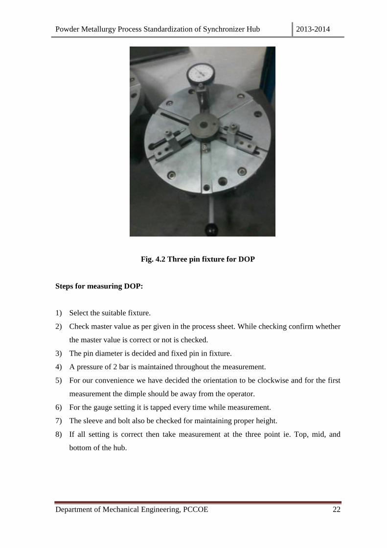
Fig. 4.2 Three pin fixture for DOP
Steps for measuring DOP:
1) Select the suitable fixture.
2) Check master value as per given in the process sheet. While checking confirm whether
the master value is correct or not is checked.
3) The pin diameter is decided and fixed pin in fixture.
4) A pressure of 2 bar is maintained throughout the measurement.
5) For our convenience we have decided the orientation to be clockwise and for the first
measurement the dimple should be away from the operator.
6) For the gauge setting it is tapped every time while measurement.
7) The sleeve and bolt also be checked for maintaining proper height.
8) If all setting is correct then take measurement at the three point ie. Top, mid, and
bottom of the hub.
Powder Metallurgy Process Standardization of Synchronizer Hub 2013-2014
Department of Mechanical Engineering, PCCOE 23
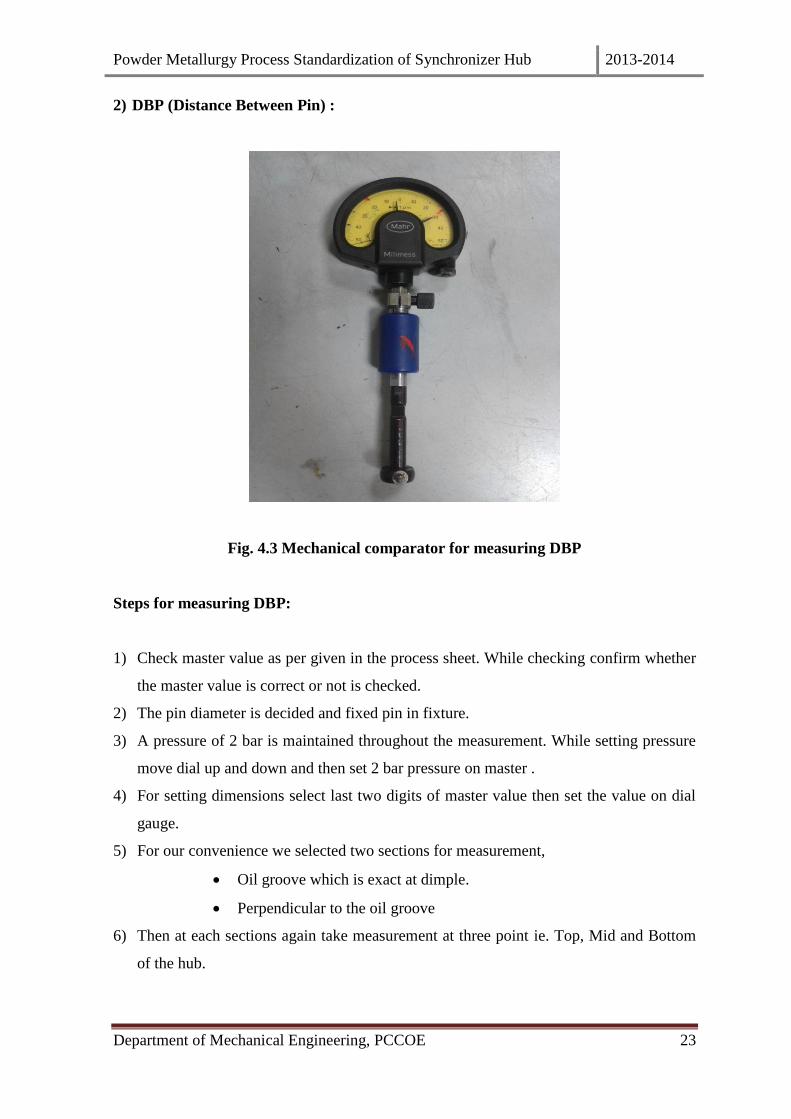
2) DBP (Distance Between Pin) :
Fig. 4.3 Mechanical comparator for measuring DBP
Steps for measuring DBP:
1) Check master value as per given in the process sheet. While checking confirm whether
the master value is correct or not is checked.
2) The pin diameter is decided and fixed pin in fixture.
3) A pressure of 2 bar is maintained throughout the measurement. While setting pressure
move dial up and down and then set 2 bar pressure on master .
4) For setting dimensions select last two digits of master value then set the value on dial
gauge.
5) For our convenience we selected two sections for measurement,
Oil groove which is exact at dimple.
Perpendicular to the oil groove
6) Then at each sections again take measurement at three point ie. Top, Mid and Bottom
of the hub.

Powder Metallurgy Process Standardization of Synchronizer Hub 2013-2014
Department of Mechanical Engineering, PCCOE 24
3) Major ID ( Major Internal Diameter) :
Fig. 4.4 Mechanical comparator for measuring major ID
Steps for measuring Major ID:
1) Check master value as per given in the process sheet. While checking confirm whether
the master value is correct or not is checked.
2) The pin diameter is decided and fixed pin in fixture. For the Major Id flat pin is
selected.
3) A pressure of 2 bar is maintained throughout the measurement. While setting pressure
move dial up and down and then set 2 bar pressure on master.
4) For setting dimensions select last two digits of master value then set the value on dial
gauge.
5) For our convenience we selected two sections for measurement,
Oil groove which is exact at dimple.
Perpendicular to the oil groove.
6) Then at each sections again take measurement at three point ie. Top, Mid and Bottom of
the hub.
Powder Metallurgy Process Standardization of Synchronizer Hub 2013-2014
Department of Mechanical Engineering, PCCOE 25
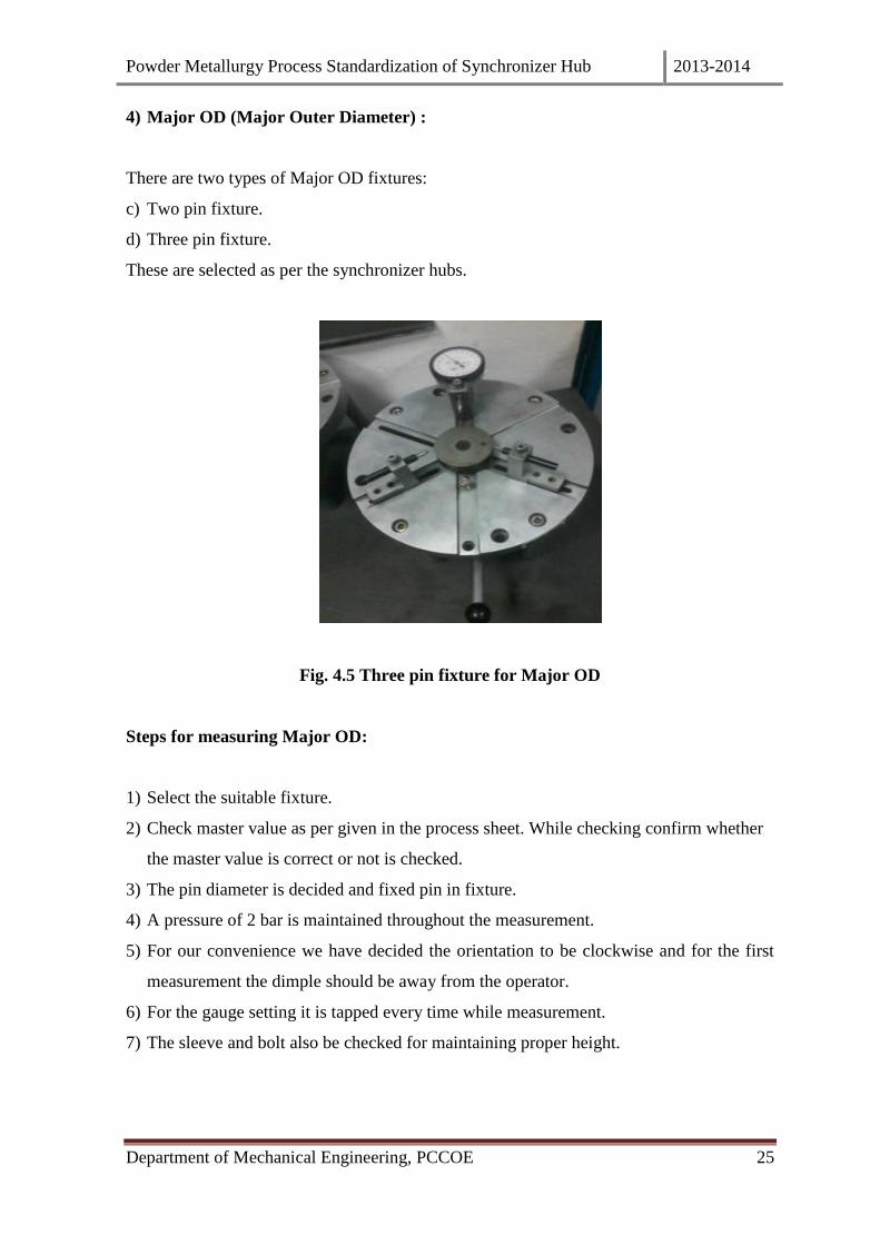
4) Major OD (Major Outer Diameter) :
There are two types of Major OD fixtures:
c) Two pin fixture.
d) Three pin fixture.
These are selected as per the synchronizer hubs.
Fig. 4.5 Three pin fixture for Major OD
Steps for measuring Major OD:
1) Select the suitable fixture.
2) Check master value as per given in the process sheet. While checking confirm whether
the master value is correct or not is checked.
3) The pin diameter is decided and fixed pin in fixture.
4) A pressure of 2 bar is maintained throughout the measurement.
5) For our convenience we have decided the orientation to be clockwise and for the first
measurement the dimple should be away from the operator.
6) For the gauge setting it is tapped every time while measurement.
7) The sleeve and bolt also be checked for maintaining proper height.

Powder Metallurgy Process Standardization of Synchronizer Hub 2013-2014
Department of Mechanical Engineering, PCCOE 26
8) For measurement of the Major OD the ball rest on outer surface of the teeth of hub at
exact middle of the teeth.
9) If all setting is correct then take measurement at the three point ie. Top, mid, and
bottom of the hub.

Powder Metallurgy Process Standardization of Synchronizer Hub 2013-2014
Department of Mechanical Engineering, PCCOE 27
Dimensions taken by conventional method:
Forming Dimensions:
Table No. 1. Forming Dimensions
Initially we have measured the dimensions after forming for this, first the master value was
set for a pressure of 2 bar.
Then it was checked for three positions i.e. top, mid and bottom.
The sectional density of green part is also checked only after forming.
ParameterForming
specificationRow average
Min. Max. 1 2 3 4 5
Area [mm2] 2939.34 2939.34 2939.34 2939.34 2939.34
Compaction force
[kN]1686.4 1676.6 1689.1 1684.8 1686.3
Compaction
pressure [MPa]574 570 575 573 574
Weight [gm] 256.400 261.600 259.65 259.27 259.81 259.52 259.78
Top 71.512 71.510 71.513 71.512 71.513 71.512
Middle 71.504 71.501 71.502 71.502 71.503 71.502
Bottom 71.461 71.459 71.459 71.459 71.460 71.460
Top 66.553 66.556 66.554 66.552 66.553 66.554
Bottom 66.498 66.499 66.502 66.499 66.503 66.500
Top 32.981 32.983 32.982 32.982 32.989 32.983
Bottom 32.973 32.973 32.977 32.977 32.973 32.975
Top 30.882 30.875 30.880 30.881 30.883 30.880
Bottom 30.878 30.877 30.878 30.880 30.878 30.878
Top - Max 74.452 74.450 74.453 74.454 74.448 74.451
Top-Min 74.448 74.446 74.449 74.446 74.448 74.447
Middle - Max 74.439 74.439 74.440 74.438 74.433 74.438
Middle - Min 74.435 74.436 74.438 74.428 74.428 74.433
Bottom - Max 74.422 74.423 74.424 74.424 74.422 74.423
Bottom - Min 74.415 74.422 74.420 74.419 74.418 74.419
Top - Max 28.657 28.655 28.652 28.651 28.653 28.654
Top-Min 28.652 28.652 28.650 28.650 28.649 28.651
Middle - Max 28.660 28.655 28.657 28.656 28.656 28.657
Middle - Min 28.657 28.654 28.655 28.656 28.656 28.656
Bottom - Max 28.657 28.657 28.654 28.654 28.654 28.655
Bottom - Min 28.653 28.654 28.653 28.653 28.653 28.653
5.646 5.644 5.642 5.645 5.647 5.645
5.631 5.629 5.623 5.627 5.630 5.628
5.613 5.602 5.609 5.614 5.615 5.611
5.631 5.630 5.632 5.632 5.630 5.631
5.632 5.630 5.635 5.636 5.635 5.634
5.635 5.626 5.631 5.632 5.632 5.631
Forming Specification Forming Dimension
Major Dia OD 71.470 71.520
Minor Dia ID 30.860 30.900
Minor Dia OD 66.520 66.570
Major Dia ID 32.970 33.000
Top
Bottom
Slot Width 5.600 5.635
DOP 74.390 74.440
DBP 28.650 28.690

Powder Metallurgy Process Standardization of Synchronizer Hub 2013-2014
Department of Mechanical Engineering, PCCOE 28
Sintering Dimensions:
Table No. 2. Sintering Dimensions
For sintering in conventional method only the belt speed and temperature are noted.
The part moves throughout the furnace for three hours and the dimensions checking
process is repeated with reference to master value.
The hardness of the part is also checked at various points on the web and boss as per the
specification on customer drawing.
ParameterSintering
specificationRow average
Min Max 1 2 3 4 5
Top 71.547 71.553 71.552 71.555 71.548 71.551
Middle 71.560 71.559 71.564 71.558 71.557 71.560
Bottom 71.530 71.528 71.535 71.538 71.528 71.532
Top 66.587 66.594 66.589 66.595 66.586 66.590
Bottom 66.566 66.561 66.570 66.571 66.564 66.566
Top 33.013 33.009 33.012 33.010 33.007 33.010
Bottom 33.006 33.001 33.008 33.003 33.006 33.005
Top 30.912 30.919 30.913 30.910 30.908 30.912
Bottom 30.906 30.900 30.907 30.896 30.905 30.903
Top-Max 74.540 74.521 74.545 74.532 74.540 74.536
Top - Min 74.504 74.507 74.498 74.520 74.505 74.507
Middle - Max 74.510 74.481 74.498 74.498 74.510 74.499
Middle - Min 74.485 74.483 74.480 74.480 74.485 74.483
Bottom - Max 74.504 74.468 74.463 74.480 74.473 74.478
Bottom - Min 74.460 74.457 74.453 74.452 74.462 74.457
Top-Max 28.690 28.700 28.685 28.697 28.683 28.691
Top - Min 28.676 28.671 28.675 28.670 28.668 28.672
Middle - Max 28.693 28.702 28.690 28.698 28.688 28.694
Middle - Min 28.680 28.681 28.680 28.680 28.676 28.679
Bottom - Max 28.690 28.677 28.680 28.680 28.680 28.681
Bottom - Min 28.668 28.672 28.670 28.675 28.667 28.670
5.626 5.643 5.632 5.626 5.635 5.632
5.610 5.606 5.620 5.606 5.612 5.611
5.618 5.611 5.613 5.611 5.611 5.613
5.646 5.631 5.638 5.623 5.643 5.636
5.633 5.631 5.628 5.624 5.635 5.630
5.638 5.642 5.629 5.645 5.637 5.638
5.590
Sintering Specification Sintering Dimension
Top
Bottom
5.640Slot Width
DBP
DOP
33.020
30.870
Major Dia ID
Minor Dia OD
Major Dia OD
28.660 28.700
74.420 74.470
30.920Minor Dia ID
66.550 66.600
32.980
71.55071.500
Powder Metallurgy Process Standardization of Synchronizer Hub 2013-2014
Department of Mechanical Engineering, PCCOE 29
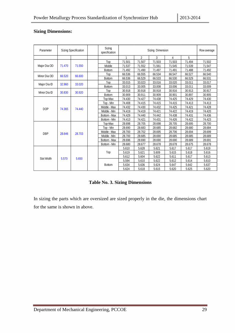
Sizing Dimensions:
Table No. 3. Sizing Dimensions
In sizing the parts which are oversized are sized properly in the die, the dimensions chart
for the same is shown in above.
ParameterSizing
specificationRow average
1 2 3 4 5
Top 71.501 71.507 71.503 71.503 71.494 71.502
Middle 71.537 71.552 71.561 71.545 71.539 71.547
Bottom 71.492 71.490 71.497 71.491 71.488 71.492
Top 66.536 66.555 66.534 66.547 66.527 66.540
Bottom 66.536 66.529 66.533 66.530 66.529 66.531
Top 33.015 33.023 33.016 33.020 33.011 33.017
Bottom 33.013 33.005 33.008 33.006 33.011 33.009
Top 30.918 30.918 30.918 30.916 30.913 30.917
Bottom 30.909 30.911 30.909 30.901 30.897 30.905
Top-Max 74.430 74.427 74.438 74.425 74.429 74.430
Top - Min 74.408 74.415 74.415 74.415 74.413 74.413
Middle - Max 74.432 74.430 74.432 74.425 74.421 74.428
Middle - Min 74.419 74.419 74.421 74.422 74.419 74.420
Bottom - Max 74.429 74.440 74.442 74.438 74.431 74.436
Bottom - Min 74.413 74.421 74.431 74.426 74.422 74.423
Top-Max 28.698 28.705 28.698 28.705 28.695 28.700
Top - Min 28.690 28.683 28.685 28.682 28.680 28.684
Middle - Max 28.700 28.702 28.695 28.706 28.694 28.699
Middle - Min 28.700 28.685 28.690 28.685 28.685 28.689
Bottom - Max 28.696 28.690 28.690 28.690 28.689 28.691
Bottom - Min 28.680 28.677 28.678 28.678 28.675 28.678
5.610 5.628 5.621 5.617 5.617 5.619
5.619 5.621 5.609 5.615 5.618 5.616
5.612 5.604 5.622 5.611 5.617 5.613
5.594 5.610 5.622 5.612 5.614 5.610
5.634 5.636 5.624 5.647 5.642 5.637
5.624 5.618 5.615 5.620 5.625 5.620
Top
Bottom
5.570
71.470
DOP 74.440
Major Dia ID 33.020
DBP 28.703
Slot Width 5.650
30.830 30.920
74.365
28.646
32.960
Minor Dia ID
Major Dia OD 71.550
Sizing Specification Sizing Dimension
Minor Dia OD 66.60066.520

Powder Metallurgy Process Standardization of Synchronizer Hub 2013-2014
Department of Mechanical Engineering, PCCOE 30
Heat Treatment Dimensions:
Table No. 4. Heat Treatment Dimensions
To enhance the mechanical property like hardness, mechanical strength next step is
hardening.
The dimensions after hardening are taken which are displayed above.
Checklist:
The conventional method of measurement were leading to variations in dimensions
which in turn was leading to more scraping of parts.
Hence we prepared a standard checklist to reduce the scraping of parts and increase the
production rate.
This check list is shown below (fig. no.)
ParameterHeat Treatment
specificationRow average
Top 71.542 71.530 71.538 71.539 71.537 71.537
Middle 71.545 71.557 71.546 71.558 71.542 71.550
Bottom 71.504 71.526 71.524 71.500 71.510 71.513
Top 66.588 66.573 66.582 66.582 66.577 66.580
Bottom 66.540 66.557 66.563 66.539 66.549 66.550
Top 32.993 32.993 32.996 32.998 32.988 32.994
Bottom 32.965 32.964 32.988 32.958 32.982 32.971
Top 30.898 30.892 30.895 30.893 30.892 30.894
Bottom 30.882 30.880 30.881 30.881 30.878 30.880
Top-Max 74.438 74.439 74.449 74.432 74.439 74.439
Top - Min 74.420 74.428 74.428 74.429 74.423 74.426
Middle - Max 74.418 74.424 74.428 74.424 74.424 74.424
Middle - Min 74.417 74.420 74.412 74.420 74.413 74.416
Bottom - Max 74.436 74.455 74.452 74.439 74.445 74.445
Bottom - Min 74.428 74.433 74.442 74.429 74.438 74.434
Top-Max 28.675 28.681 28.673 28.685 28.668 28.676
Top - Min 28.650 28.660 28.657 28.660 28.655 28.656
Middle - Max 28.684 28.690 28.678 28.675 28.677 28.681
Middle - Min 28.674 28.669 28.655 28.668 28.656 28.664
Bottom - Max 28.665 28.667 28.665 28.660 28.660 28.663
Bottom - Min 28.647 28.655 28.647 28.648 28.645 28.648
5.638 5.669 5.617 5.653 5.640 5.643
5.650 5.657 5.656 5.651 5.649 5.653
5.649 5.663 5.617 5.656 5.638 5.645
5.655 5.633 5.647 5.634 5.651 5.644
5.678 5.636 5.653 5.661 5.663 5.658
5.676 5.671 5.676 5.686 5.683 5.678
66.500
32.930Major Dia ID 33.029
DOP
Heat Treatment
SpecificationHeat Treatment Dimension
Minor Dia OD 66.600
Major Dia OD 71.55071.450
DBP 28.703
74.345
28.636
30.940
Top
Slot Width 5.650
Minor Dia ID
Bottom
5.550
30.800
74.445

Powder Metallurgy Process Standardization of Synchronizer Hub 2013-2014
Department of Mechanical Engineering, PCCOE 31
Table No.5 Checklist
Through this checklist we analysed every parameter from powder mixing to hardening.

Powder Metallurgy Process Standardization of Synchronizer Hub 2013-2014
Department of Mechanical Engineering, PCCOE 32
(Note: The powder is supplied by Hogonus Ltd. Therefore no changes are made in its
compositions in the company.)
Forming Dimensions:
In conventional method, we take the dimensions after each process but according to
checklist.
In forming we have also noted the compaction force, weight and compaction pressure for
each part under observance.
The tool dimensions for the same part are also noted.
The dimensions for the part are entered in the table and their average value is calculated.
The sprinback is calculated by the following formula,
Sprinback = (Avg. dimensions – tool dimensions) / tool dimensions

Powder Metallurgy Process Standardization of Synchronizer Hub 2013-2014
Department of Mechanical Engineering, PCCOE 33
Para
meter
Form
ing
Row
aver
age
Over
all av
erag
e
Min.
Max
.1
24
5
Area
[mm2
]29
39.34
2939
.3429
39.34
2939
.34
Comp
actio
n for
ce
[kN]
1752
.317
55.1
1755
.517
60.8
Comp
actio
n
pres
sure
[MPa
]59
659
759
759
9
Weig
ht [g
m]25
6.400
261.6
0025
8.528
258.5
7525
8.706
258.7
28
Top
71.51
271
.510
71.51
271
.513
71.51
271
.269
0.34
Midd
le71
.504
71.50
171
.502
71.50
371
.502
71.26
90.3
3
Botto
m 71
.461
71.45
971
.459
71.46
071
.460
71.26
90.2
7
Top -
Max
33.00
032
.992
32.99
932
.994
32.99
6
Top-
Min
32.95
032
.955
32.94
832
.950
32.94
9
Midd
le - M
ax32
.985
32.97
632
.984
32.97
532
.980
Midd
le - M
in32
.954
32.95
432
.947
32.94
932
.949
Botto
m - M
ax32
.974
32.96
532
.970
32.96
332
.968
Botto
m - M
in32
.953
32.95
432
.946
32.94
932
.948
Top -
Max
74.41
074
.405
74.40
774
.406
74.40
7
Top-
Min
74.39
274
.389
74.38
574
.393
74.39
0
Midd
le - M
ax74
.400
74.40
474
.400
74.40
374
.402
Midd
le - M
in74
.400
74.39
974
.392
74.39
874
.398
Botto
m - M
ax74
.379
74.38
074
.376
74.38
074
.378
Botto
m - M
in74
.370
74.36
574
.370
74.36
574
.369
Top -
Max
28.70
028
.699
28.70
028
.700
28.69
9
Top-
Min
28.64
328
.651
28.64
828
.650
28.64
9
Midd
le - M
ax28
.690
28.68
928
.689
28.69
028
.689
Midd
le - M
in28
.640
28.64
628
.640
28.64
428
.643
Botto
m - M
ax28
.672
28.67
128
.674
28.67
228
.672
Botto
m - M
in28
.634
28.63
728
.635
28.63
928
.637
32.96
0
74.18
6
28.66
4
0.04%
0.01%
-0.01
%
0.29%
0.047
0.031
0.020
0.017
0.004
0.010
0.01%
28.66
6
-0.03
%28
.654
0.046
0.035
0.03%
28.67
4
28.70
028
.634
28.66
5
0.050
74.36
574
.391
74.40
0
74.37
4
DBP
28.65
028
.690
DOP
74.37
074
.430
74.39
9
74.41
00.2
9%
0.25%
Majo
r Dia
ID33
.000
33.00
032
.940
32.96
532
.970
32.97
3
32.96
4
32.95
8
71.49
1M
ajor D
ia OD
71.43
071
.500
71.51
371
.459
Form
ing S
pecif
icatio
nFo
rming
Dim
ensio
nDO
P DB
P
Avg f
or
Max
.M
in.Ov
ality
Tool
dimSp
ringb
ack
Tab
le N
o.6
Form
ing D
imen
sion
s

Powder Metallurgy Process Standardization of Synchronizer Hub 2013-2014
Department of Mechanical Engineering, PCCOE 34
Sintering Dimensions:
Para
meter
Sinter
ing
Spec
ificati
on
12
45
Row
Avg.
Form
Dim
.DC
Ovali
ty
DOP
DBP
Avg f
or
grap
hs
Max
.M
in.Av
erag
e
Top
71.54
771
.553
71.55
571
.548
71.55
171
.512
0.05%
Midd
le71
.560
71.55
971
.558
71.55
771
.560
71.50
20.0
8%
Botto
m 71
.530
71.52
871
.538
71.52
871
.532
71.46
00.1
0%
Top-
Max
33.01
233
.008
33.00
433
.010
33.00
932
.996
Top -
Min
32.96
632
.970
32.97
332
.970
32.97
032
.949
Midd
le - M
ax33
.005
33.00
433
.004
33.00
333
.004
32.98
0
Midd
le - M
in32
.970
32.97
232
.971
32.97
332
.972
32.94
9
Botto
m - M
ax33
.003
33.00
533
.009
33.00
233
.004
32.96
8
Botto
m - M
in32
.976
32.97
932
.975
32.97
932
.978
32.94
8
Top-
Max
74.40
974
.417
74.41
874
.419
74.41
674
.407
Top -
Min
74.40
274
.391
74.40
074
.410
74.40
374
.390
Midd
le - M
ax74
.411
74.41
274
.428
74.42
774
.421
74.40
2
Midd
le - M
in74
.407
74.40
874
.411
74.42
374
.414
74.39
8
Botto
m - M
ax74
.404
74.40
574
.422
74.42
274
.415
74.37
8
Botto
m - M
in74
.397
74.39
374
.404
74.40
974
.402
74.36
9
Top-
Max
28.70
528
.700
28.69
628
.704
28.70
228
.699
Top -
Min
28.66
028
.664
28.66
528
.665
28.66
428
.649
Midd
le - M
ax28
.710
28.70
728
.708
28.71
028
.709
28.68
9
Midd
le - M
in28
.665
28.66
628
.669
28.67
128
.668
28.64
3
Botto
m - M
ax28
.696
28.69
928
.702
28.69
728
.698
28.67
2
Botto
m - M
in28
.664
28.66
428
.664
28.66
728
.665
28.63
7
0.05%
0.03%
0.08%
0.10%
0.05%
0.07%
0.10%
0.01%
0.02%
0.041
0.033
0.032
0.027
0.014
0.007
0.013
0.038
28.68
428
.689
28.68
2
74.41
8
74.40
9
DBP
28.66
028
.700
28.68
3
28.71
028
.660
DOP
74.39
074
.440
74.41
0
74.42
874
.391
74.41
2
32.98
9M
ajor D
ia ID
32.98
033
.020
33.01
232
.966
32.98
9
32.98
8
32.99
1
0.039
71.52
871
.547
Sinter
ing
Majo
r Dia
OD71
.480
71.53
071
.564
Tab
le N
o.
7 S
inte
rin
g D
imen
sion
s
Powder Metallurgy Process Standardization of Synchronizer Hub 2013-2014
Department of Mechanical Engineering, PCCOE 35
In sintering we checked the belt speed with the help of scale and stopwatch for 1 m. length
(standard belt speed should be 128 mm/min).
We have noted the temperatures of all zones and also the compositions of gases like
Nitrogen, Ammonia and LPG in m3/hrs to avoid the oxidation of the part.
The dew point temperature and blower rpm are also noted.
The furnace constitutes of four zones,
Preheating zone (temp. 10000C)
Actual sintering zone
Sintering hardness zone (840 – 11400C)
Fast cooling zone
The hub is mounted on ceramic bobbin since ceramic can sustain in system high
temperature and the part gets equally heated from all sides.
After sintering the hardness of the part is checked.

Powder Metallurgy Process Standardization of Synchronizer Hub 2013-2014
Department of Mechanical Engineering, PCCOE 36
Sizing Dimensions:
For sizing process, we note the tool dimensions and part are sized in the die.
The spring back of part are calculated after sizing.
Machining is done only if required and it is done only on Boss and web.
Param
eter
12
45
Row A
vg.To
ol Dim
Spring
back
Ovalit
y
DOP D
BP
Avg f
or
graphs
Max.
Min.
Avera
ge
Top
71.501
71.507
71.503
71.494
71.501
-0.03%
Middl
e71.
51271.
55271.
50971.
50371.
5190.0
0%
Bottom
71.
49271.
49071.
49171.
48871.
490-0.
04%
Top-M
ax33.
00933.
00133.
00033.
00633.
004
Top -
Min
32.961
32.962
32.966
32.962
32.963
Middl
e - M
ax32.
99732.
99632.
99732.
99732.
997
Middl
e - M
in32.
96332.
96332.
96232.
96532.
963
Bottom
- Max
32.993
32.994
33.000
32.994
32.995
Bottom
- Min
32.968
32.967
32.964
32.970
32.967
Top-M
ax74.
38474.
38474.
38374.
38274.
383
Top -
Min
74.374
74.374
74.377
74.378
74.376
Middl
e - M
ax74.
41074.
40974.
41274.
40974.
410
Middl
e - M
in74.
40174.
40374.
40574.
40474.
403
Bottom
- Max
74.373
74.374
74.383
74.378
74.377
Bottom
- Min
74.366
74.368
74.355
74.368
74.364
Top-M
ax28.
70828.
70028.
69828.
70428.
703
Top -
Min
28.663
28.663
28.665
28.662
28.663
Middl
e - M
ax28.
71428.
71028.
70828.
71128.
711
Middl
e - M
in28.
67028.
67028.
67028.
66928.
670
Bottom
- Max
28.696
28.695
28.699
28.695
28.696
Bottom
- Min
28.660
28.660
28.659
28.661
28.660
71.521
74.350
28.668
0.04%
0.08%
0.03%
0.041
0.036
0.033
0.028
0.008
28.714
28.659
28.684
28.690
28.678
74.407
74.371
DBP
28.646
28.703
28.683
0.007
0.013
0.039
DOP
74.335
74.410
74.380
74.412
74.355
74.386
32.982
Major
Dia ID
32.960
33.020
33.009
32.961
32.983
32.980
32.981
0.041
Sizing
Speci
fication
Sizing
Major
Dia OD
71.460
71.520
71.552
71.488
71.504
0.001
0.001
0.000
33.021
-0.001
-0.001
-0.001
Tab
le N
o.8
Siz
ing D
imen
sion
s
Powder Metallurgy Process Standardization of Synchronizer Hub 2013-2014
Department of Mechanical Engineering, PCCOE 37
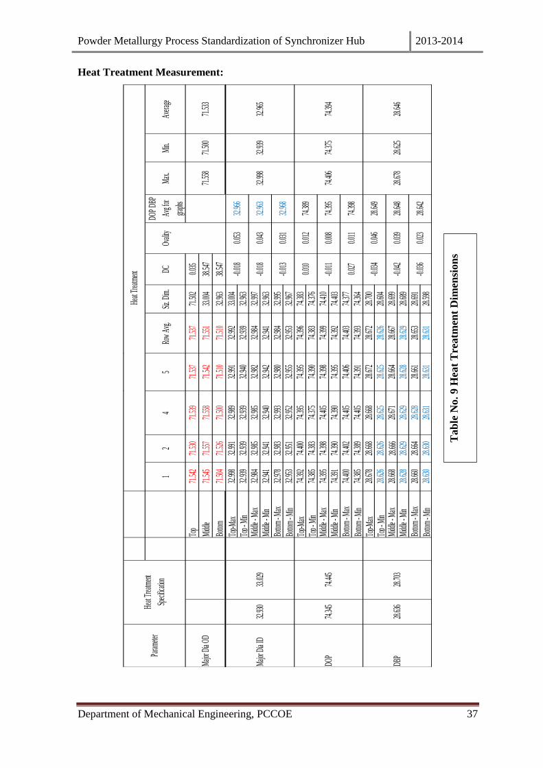
Heat Treatment Measurement:
12
45
Row
Avg.
Siz. D
im.
DCOv
ality
DOP
DBP
Avg f
or
graph
s
Max
.M
in.Av
erage
Top
71.54
271
.530
71.53
971
.537
71.53
771
.502
0.035
Midd
le71
.545
71.55
771
.558
71.54
271
.551
33.00
438
.547
Botto
m 71
.504
71.52
671
.500
71.51
071
.510
32.96
338
.547
Top-M
ax32
.998
32.99
132
.989
32.99
132
.992
33.00
4
Top -
Min
32.93
932
.939
32.93
932
.940
32.93
932
.963
Midd
le - M
ax32
.984
32.98
532
.985
32.98
232
.984
32.99
7M
iddle
- Min
32.94
132
.941
32.94
032
.942
32.94
132
.963
Botto
m - M
ax32
.978
32.98
332
.993
32.98
032
.984
32.99
5
Botto
m - M
in32
.953
32.95
132
.952
32.95
532
.953
32.96
7
Top-M
ax74
.392
74.40
074
.395
74.39
574
.396
74.38
3
Top -
Min
74.38
574
.383
74.37
574
.390
74.38
374
.376
Midd
le - M
ax74
.395
74.39
874
.405
74.39
874
.399
74.41
0M
iddle
- Min
74.39
174
.390
74.39
074
.395
74.39
274
.403
Botto
m - M
ax74
.400
74.40
274
.405
74.40
674
.403
74.37
7
Botto
m - M
in74
.385
74.38
974
.405
74.39
174
.393
74.36
4
Top-M
ax28
.678
28.66
828
.668
28.67
228
.672
28.70
0
Top -
Min
28.62
628
.626
28.62
528
.625
28.62
628
.604
Midd
le - M
ax28
.668
28.66
628
.671
28.66
428
.667
28.69
9M
iddle
- Min
28.62
828
.629
28.62
928
.628
28.62
928
.689
Botto
m - M
ax28
.660
28.66
428
.628
28.66
128
.653
28.69
1
Botto
m - M
in28
.630
28.63
028
.631
28.63
128
.631
28.59
8
-0.03
4
-0.04
2
-0.03
6
-0.01
8
-0.01
8
-0.01
3
0.010
-0.01
1
0.027
0.039
0.023
0.053
0.043
0.031
0.012
28.67
828
.625
28.64
628
.648
28.64
2
74.39
5
74.39
8
DBP
28.63
628
.703
28.64
9
0.008
0.011
0.046
DOP
74.34
574
.445
74.38
9
74.40
674
.375
74.39
4
Majo
r Dia
ID33
.029
32.99
832
.939
32.96
532
.930
32.96
6
32.96
3
32.96
8
71.53
3M
ajor D
ia OD
71.55
871
.500
Param
eter
Heat
Trea
tmen
t
Spec
ificati
on
Heat
Trea
tmen
t
Tab
le N
o. 9
Hea
t T
reatm
ent
Dim
ensi
on
s

Powder Metallurgy Process Standardization of Synchronizer Hub 2013-2014
Department of Mechanical Engineering, PCCOE 38
We are noted the temperatures of all zones and also the compositions of gases like
Nitrogen, Ammonia and LPG in m3/hrs to avoid of the part the oxidations of the part.
The dew point temperature and blower rpm are also note.
The hub is mounted on ceramic bobbin since ceramic can sustain in system high
temperature and the part gets equally heated from all sides.
After sintering the hardness of the part is checked.
Pallets making:
Pallets are pressed using UTM (Universal Testing Machine) to check the actual
springback and compressibility of the component.
Pallets are prepared from the same mix as that of the part and are sintered at same
temperature.
The pallets dimensions checked are Diameter, height and Weight.
The standard pressure of 400 MPa, 500MPa, 600 MPa and 650 MPa are set on the
UTM.
The density of pallets are calculated as follows,
Density ( ϱ) = Mass/ Volume
Volume = (π/4)* d2*h
The graph of density Vs pressure and spring back Vs Green density is plotted as shown in
the fig.

Powder Metallurgy Process Standardization of Synchronizer Hub 2013-2014
Department of Mechanical Engineering, PCCOE 39
Table No.10.Pallet Dimensions
Fig. 4.6 Density Vs Compaction Pressure
Powder Metallurgy Process Standardization of Synchronizer Hub 2013-2014
Department of Mechanical Engineering, PCCOE 40
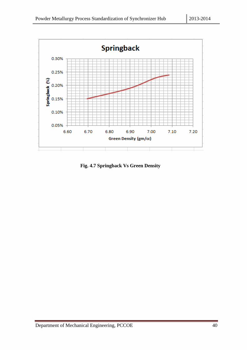
Fig. 4.7 Springback Vs Green Density

Powder Metallurgy Process Standardization of Synchronizer Hub 2013-2014
Department of Mechanical Engineering, PCCOE 41
5. RESULT AND DISCUSSIONS:
Fig.5.1 DOP Variation (Before)
Fig.5.2 DOP Variation (After)
74.320
74.340
74.360
74.380
74.400
74.420
74.440
74.460
74.480
74.500
74.520
74.540
Forming Sintering Sizing Heat Treatment
DOP taper
UL
LL
Tool
ActualDim
ensi
on
s in
mm
74.320
74.340
74.360
74.380
74.400
74.420
74.440
74.460
Forming Sintering Sizing Heat Treatment
DOP taper
UL
LL
Tool
Actual
Dim
ensi
on
s in
mm
Processes
Processes
Powder Metallurgy Process Standardization of Synchronizer Hub 2013-2014
Department of Mechanical Engineering, PCCOE 42
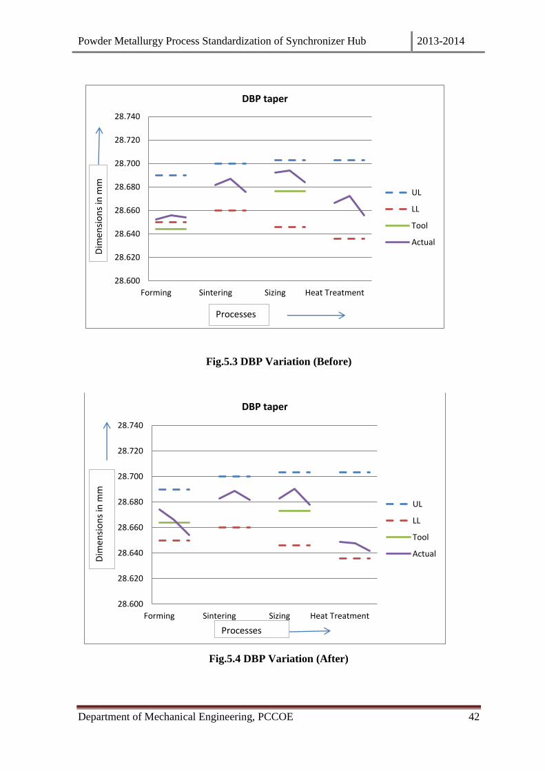
Fig.5.3 DBP Variation (Before)
Fig.5.4 DBP Variation (After)
28.600
28.620
28.640
28.660
28.680
28.700
28.720
28.740
Forming Sintering Sizing Heat Treatment
DBP taper
UL
LL
Tool
Actual
28.600
28.620
28.640
28.660
28.680
28.700
28.720
28.740
Forming Sintering Sizing Heat Treatment
DBP taper
UL
LL
Tool
Actual
Processes
Dim
ensi
on
s in
mm
Processes
Dim
ensi
on
s in
mm

Powder Metallurgy Process Standardization of Synchronizer Hub 2013-2014
Department of Mechanical Engineering, PCCOE 43
Fig.5.5 Major ID Variation (Before)
Fig.5.6 Major ID Variation (After)
32.860
32.880
32.900
32.920
32.940
32.960
32.980
33.000
33.020
33.040
33.060
33.080
Forming Sintering Sizing Heat Treatment
Major ID taper
UL
LL
Actual
32.860
32.880
32.900
32.920
32.940
32.960
32.980
33.000
33.020
33.040
33.060
33.080
Forming Sintering Sizing Heat Treatment
Major ID taper
UL
LL
Actual
Processes
Dim
ensi
on
s in
mm
Processes
Dim
ensi
on
s in
mm
Powder Metallurgy Process Standardization of Synchronizer Hub 2013-2014
Department of Mechanical Engineering, PCCOE 44
6. CONCLUSIONS:-
1) Major variation in dimensions are seen in four parameters DOP, DBP, Major ID and Major
OD and we have selected them for our project purpose. Every minor change at every step is
noted and it is seen that on an average the top portion of the hub has major deviation i.e. the
hub appears to be slight taper.
2) The apparent density is the ratio of volume to weight of loosely filled mixture and it is
between 2.95 to 3.2 gm/cc. The flow of powder is for 30 sec max.
3) P/M technology has density dependent properties. Hence, compaction force has significant
effect on the properties of the component. The density specification for various synchronizer
hubs may vary from a minimum of 6.8gm/cc to a maximum of 7.1gm/cc. The variation of
density Vs compaction force is shown in fig no.4.6
4) The springback of the hub depends on compaction pressure. As the compaction pressure
increases, springback increases. The springpack of pellets and the parts is different. It is
more for the pellets than that of the part.
5) The change in dimensions in pellet and part are noted as shown in table no.10. The
dimensional change in such a record is useful in tool selection and also in regular production.
6) We have used two sided compaction method. Hence continuous usage of punch wears it
which leads to variation in fill height. The variation in fill height affects the sectional density
measured after forming. With increasing distance from the face of the compacting punch, the
axial stress which is available for the local densification of the powder decreases. , maximum
variation in the geometry of synchronizer hub is observed after sintering.
7) Compaction force and springback are interdependent. The calculation of springback gives us
values which we can use to study the condition of tool. If it is observed that the springback
values are more than expected, it is an indication to us to change the tool or redesign the tool.
Thus the springback is an important factor for tool design. The compressibility curve

Powder Metallurgy Process Standardization of Synchronizer Hub 2013-2014
Department of Mechanical Engineering, PCCOE 45
(shown in fig no.4.6) helps us to understand how green density changes with the change in
compaction pressure. For example if we select 500 MPa pressure for a particular component
we get density as 6.9 gm/cc , but in regular practice if this value changes to +-500 , the small
change in green density is not possible to note. But this leads to change in tool dimensions
and its affects the part geometry.
8) We have kept a constant belt speed of 128mm/min (depend on length of sintering zone) since
variation in belt speed leads to the component being subjected to less or more amount of heat
which in turn affects the geometry of the component.
9) During sizing, only the radial dimensions are controlled i.e. taper reduction and profile
improvement is done. If there is taper, it becomes difficult for the hub to fit into the
assembly.

Powder Metallurgy Process Standardization of Synchronizer Hub 2013-2014
Department of Mechanical Engineering, PCCOE 46
7. REFERENCES:-
[1] A.K.Sinha “Powder Metallurgy”.
[2] Shidney Avner “Introduction to Physical Metallurgy”.
[3] V.D.Kodgire “Material Science and Metallurgy for Engineers”.
[4] Myeong-Sik Jeong a, Jun-HwanYoo b, Sung-HanRhim c, Sang-KonLee a, Soo-IkOhb,n “A
unified model for compaction and sintering behaviour of powder processing”.
[5] www.sciencedirect.com
[6] H.Hofmann, P.Bowen “Powder Technology”.
[7] Ottmar Back, Head of Product Management “Basics of Synchronizers”.
[8] ANA PASTOR BEDMAR “Synchronization processes and synchronizer mechanisms
in manual transmissions” Modelling and simulation of synchronization processes
Department of Applied Mechanics Division of Dynamics CHALMERS
UNIVERSITY OF TECHNOLOGY Goteborg, Sweden 2013.
[9] Manufacturing Science and Technology.