Final Element 1st 2016 - Pakistan Foundry Association Element... · 2016-05-23 · I am highly...
40
ELEMENT Your Guide to Foundries in Pakistan www.pfa.org.pk 1st Quarter 2016 Industrializing Pakistan
Transcript of Final Element 1st 2016 - Pakistan Foundry Association Element... · 2016-05-23 · I am highly...

ELEMENTYour Guide to Foundries in Pakistan
www.pfa.org.pk1st Quarter 2016
Industrializing Pakistan
Waste Is The Enemy
Interactive Foundry Training Workshop News on Mo ld & Core mak ing technology
2
5
20
10
28
32
1
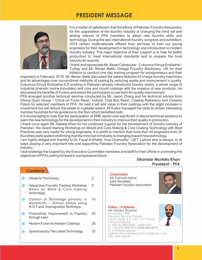
It is a matter of satisfaction that the efforts of Pakistan Foundry Association for the upgradation of the foundry industry is changing the mind set and arising interest of PFA members to adopt new foundry skills and technology. During the last international foundry congress and exhibition-2014 certain multinationals offered their services to train our young engineers for their development in technology and introduction to modern foundry industry. The major objective of their support is to help for better production to meet international standards and to prepare the local industry for exports. I thank and appreciate Mr. Baser Oztopcular - Çukurova Kimya Endüstrisi - Turkey and Mr. Benan Betik- Omega Foundry Machinery- UK for their initiative to conduct one day training program for entrepreneurs and their
engineers in February, 2016. Mr. Benan Betik discussed the salient features of omega foundry machinery and its advantages over conventional methods of casting by reducing waste and improvement in quality. Çukurova Kimya Endüstrisi A.S working in Pakistan already introduced foundry resins, a whole range of industrial phenolic resins (novolaks) and core and mould coatings with the impetus of new products. He discussed the benefits of Furans and asked the participants to use them for quality improvement. PFA arranged another technical seminar conducted by Mr. Jason Zhang and his technical advisor from Sheng Quan Group – China on Furan Resin, furfural, Cold Box Resin, Coating Refractory and Ceramic Filters for selected members of PFA. He said it will add value in their castings with the slight increase in investment but will reduce the waste to a greater extent. PFA also managed his visits to certain interesting member foundries for his guidance on the floor which benefited both.It is encouraging to note that the participation of SME sector was significant in above technical sessions to learn the new technology for the development in their industry to improve their quality in production.I thank once again Mr. Nabeel Khan for his continued support for the development of foundry industry of Pakistan. His recent training Workshop on Mould and Core Making & Core Coating Technology with Best Practices was very useful for young engineers. It is worth to mention that more than 40 engineers from 22 foundries participated confirming that the mind set of industry is changing toward new technology. I am highly obliged and thankful to Dr. Fazal-A-Khalid, Vice-Chancellor - UET, Lahore who is always, in all ways playing a very important role and supporting Pakistan Foundry Association for the development of industry. I acknowledge the support by the Executive Committee members and staff for their efforts in promoting the objectives of PFA Looking forward to a progressive future.
-0300 8673873
Joint SecretaryPakistan Foundry Association
Control of Shrinkage porosity in Aluminium – Silicon Alloys using N.D.T.and Impregnation Technique
Productivity Improvement in Foundry through Lean
Modern Furan for Modern Castings
Spectroscopy The Latest Technology
goods or servicesl Takes the focus away from what the customer really wantsl Leads to excessive inventoryCaused byl MRP push rather than pulll Large batch sizesl Looks better to be busy!l Poor people utilisationLack of customer focus Why one of the 7 Wastes?l Costs moneyl Consumes resource ahead of planl Creates inventoryl Hides inventory/defect problemsl Space utilisation2. InventoryAny raw material, work in progress (WIP) or finished goods which are not having value added to themCaused byl Production schedule not levell Inaccurate forecastingl Excessive downtime/set upl Push instead of pulll Large batchingl Unreliable suppliersWhy one of the 7 Wastes?l Adds costl Extra storage space requiredl Extra resource to managel Hides shortages & defectsl Can become damagedl Shelf life expires3. Motionl Adds costl Motion is the movement of "man”l Waste motion occurs when individuals move more than is necessary for the process to be completedCaused byl No standard operating procedurel Poor house keepingl Badly designed celll Inadequate trainingWhyoneofthe7Wastes?l It interrupts production flowl Increases production time
A True Story!When I started leading my company into exports in 1994, I got a rude shock that prices of truck parts made at our plant were similar to prices of parts made in Germany! Why would anyone buy from a company located in Islamabad, Pakistan at German price?This rude shock forced me to look at my manufacturing floor. I was wondering about my manufacturing floor. I wondered how was It that my company, which had no debts, no rent costs, employees costing a fraction of European labour, electricity well below European rates, with metal bought on internationaI prices ,was not competitive in the European market!I spent the next few months just wandering about my manufacturing floor, before a pattern began to emerge and I started to understand the reason for our high costs. To make a long story short, I noticed wastes in our processes and plant layout. The whole process was rewritten, and this resulted in reducing our cost of production by 24% in one go!All the learning from management courses, overseas visits, training in Japan with AOTS started to fall in place on our factory floor. Encouraged by our success, we went to implement5-S, Lean Inventory and started paying greater attention to our supply chain through adoption of an ERP System.The export market started responding and in a short period of time our company became export oriented and, now exports heavy truck parts to more than forty countries include the United States, Europe, Middle East, South America, Africa and the Far East!I want to share with the readers the simple, common-sense list of the types of waste, which need to be taken out of text books and practiced on the shop floor.
1. Over Productionl To produce sooner, faster or in greater quantities than the absolute customer demandl Manufacturing too much, too early or"Just in Case”l Over production discourages a smooth flow of
2
increasing productivity through reducing“seven wastes”in operations
WASTE IS THE ENEMYImtiaz-A-Rastgar
CEO - Rastgar Engineering (Pvt.) Ltd

l Can cause injuryl People or parts that wait for a work cycle to be completedl Where are the bottlenecks?l What are the major causes of lost machine availability?l What are we doing to improve machine availabilityl Do people wait on machinery?Caused byl Ineffective production planningl Quality, design, engineering Issuesl 'Black art' processesl Why one of the 7 Wastes?l Stop/ Start productionl Poor work flow continuityl Causes bottlenecksl Long lead timesl Failed delivery dates4. WaitingIt is the act of doing nothing or working slowly whilst waiting for a previous step in the processWhy one of the 7 Wastes?l Time wasted has to be paid by the companyl Make up by doing over time5. Transportationl Unnecessary movement of parts between processesl Complex material flow pathsl Poor close couplingl Wasted floor spacel Unnecessary material handlingl Potential damage to productsCaused byl Badly designed process/celll Poor value stream flowl Complex material flowsl Sharing of equipment Why one of the 7 Wastes?l Increases production timel It consumes resource & floor spacel Poor communicationl Increases work in progressl Potential damage to products6. Over-ProcessingProcessing beyond the standard required by the customerBy improving processing efficiency weultimately use less resource to achieve the same customer satisfactionCaused byl Out of date standardsl Attitude- 'Always done it like this’l Not understanding the process
l Lack of innovation & improvementl Lack of standard operation procedures Why one of the 7 Wastes?l It consumes resourcel It increases production timel Can reduce life of component7. Non-Right First Time (Scrap, Rework and Defectsl A defect is a component which the customer would deem unacceptable to pass the quality standardl Defects reduce or discourage customer satisfactionl Defects have to be rectifiedl Rectification costs money with regard to time effort and materialsl Defects in the field will lose customersl Right first time is the key Caused byl Out of control/Incapable processesl Lack of skill, training & on the job supportl Inaccurate design & engineeringl Machine Inaccuracyl Black art processesWhy one of the 7 Wastes?l Adds costsl It interrupts the scheduledl It consumes resourcesl It creates paper workl Reduces customer confidenceI would like to share some more tips which I learnt through study and then practiced on my shop floor.1- Under Utilization of People.This is considered the 8th waste. People are your greatest asset; get the best out of them. As far as possible, cultivate multi-tasking workforce. "Experienced" people turn out to be a stumbling block when dealing with change in your company. Create a process chart and then for each step of the process, work out the need fora. Skillsb. Toolsc. Control limitsd. Workstatione. Safety needs etcThen go for a younger, raw workforce and create an intensive in-house training, so that each worker on each step of the process has the necessary skill for his/her work station. This is the best way of creating a sustainable human resource which you can continue to train and re-train as your process changes require.2- Review Your Process LayoutPay attention to new technologies available,
3

while also attending toa. Materials handlingb. Dis tance between machines or workstationsc. Getting rid of value-deletion activity.3- Use Low Cost Automation for repetitive tasksAlthough labor is, for unknown reasons, deemed to be cheap in Pakistan, unnecessary people on operations which are either repetitive or only pick and p lace, should be made human-less(automated); use pick and place grippers, actuators etc working on pneumatic automation. This will Not only reduce labor cost, it will also reduce the number of variables and human error from your process.4- Move Up the Value ChainLook for what more you can deliver to your customer. These are incremental or additional improvements in your process, which can improve your price by giving the customer extra value!Management guru W. Edwards Deming taught that by reducing waste companies can increase quality and simultaneously reduce costs. Regardless of the industry your company is in, you can increase profits in your company or business unit by reducing your waste.
Cut Waste Increase ProfitIn the face of ever increasing competition, rising costs, reducing waste and adopting the principles of Lean Manufacturing is the recipe for survival and generating the cash need for more productive capital investments.
Cut Waste In Your Own Management TimeThink about the time you spend in meetings about topics over which you have no authority and little input, reading waste of time emails or solving problems that shouldn't have occurred in the first place. Replace this activity to identify waste and eliminating it.There is too much waste in organizations. Whether in time, resources, talent, opportunity or any other contribution possible by people or equipment, you will find waste.The best way to identify wastes is to ask your employees. They are the people closest to the process. They are the ones dealing with the daily frustrations of wanting to improve it. So ask them. Once in a while also invite some guests from industry to visit your plant floor and encourage them to give suggestion, which may lead to improvements in your company. The results will surprise you, pleasantly!
4
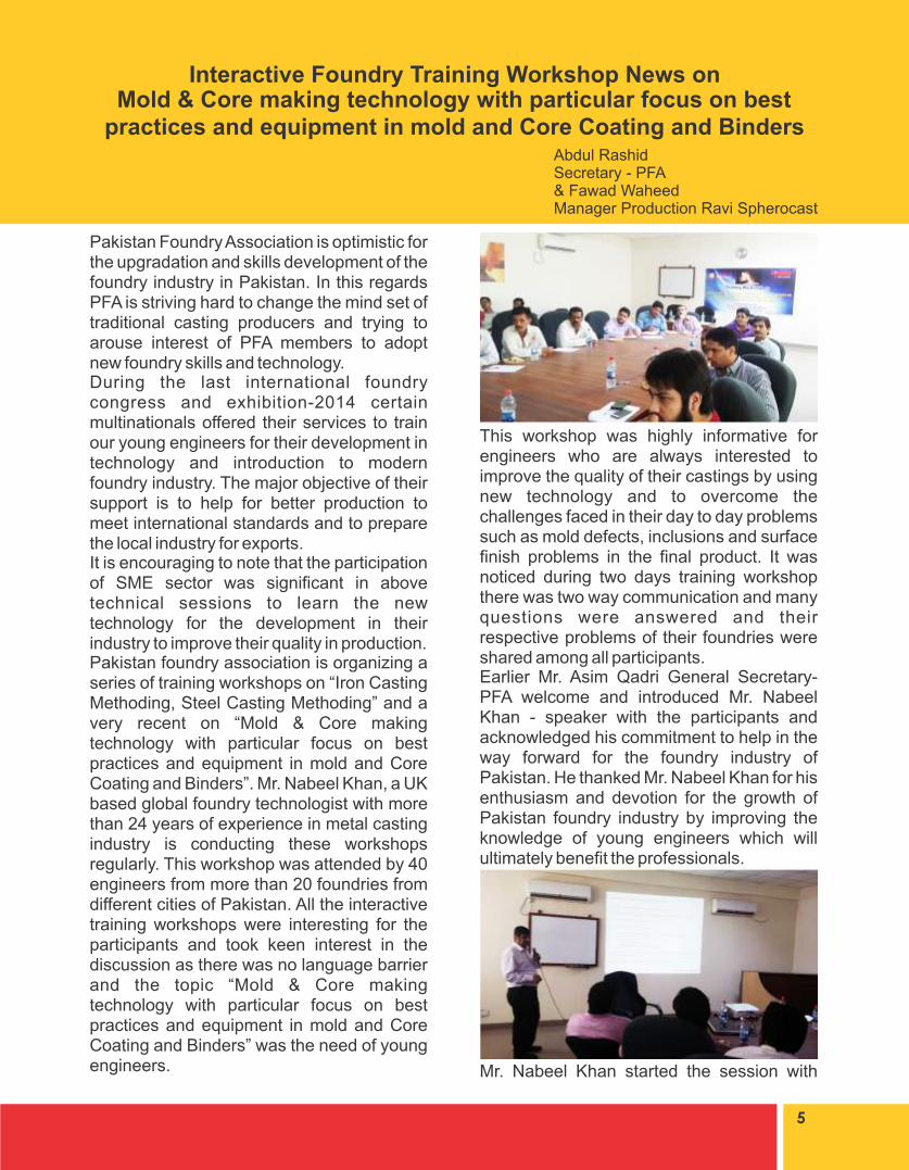
This workshop was highly informative for engineers who are always interested to improve the quality of their castings by using new technology and to overcome the challenges faced in their day to day problems such as mold defects, inclusions and surface finish problems in the final product. It was noticed during two days training workshop there was two way communication and many questions were answered and their respective problems of their foundries were shared among all participants.Earlier Mr. Asim Qadri General Secretary-PFA welcome and introduced Mr. Nabeel Khan - speaker with the participants and acknowledged his commitment to help in the way forward for the foundry industry of Pakistan. He thanked Mr. Nabeel Khan for his enthusiasm and devotion for the growth of Pakistan foundry industry by improving the knowledge of young engineers which will ultimately benefit the professionals.
Mr. Nabeel Khan started the session with
Pakistan Foundry Association is optimistic for the upgradation and skills development of the foundry industry in Pakistan. In this regards PFA is striving hard to change the mind set of traditional casting producers and trying to arouse interest of PFA members to adopt new foundry skills and technology.During the last international foundry congress and exhibition-2014 certain multinationals offered their services to train our young engineers for their development in technology and introduction to modern foundry industry. The major objective of their support is to help for better production to meet international standards and to prepare the local industry for exports.It is encouraging to note that the participation of SME sector was significant in above technical sessions to learn the new technology for the development in their industry to improve their quality in production.Pakistan foundry association is organizing a series of training workshops on “Iron Casting Methoding, Steel Casting Methoding” and a very recent on “Mold & Core making technology with particular focus on best practices and equipment in mold and Core Coating and Binders”. Mr. Nabeel Khan, a UK based global foundry technologist with more than 24 years of experience in metal casting industry is conducting these workshops regularly. This workshop was attended by 40 engineers from more than 20 foundries from different cities of Pakistan. All the interactive training workshops were interesting for the participants and took keen interest in the discussion as there was no language barrier and the topic “Mold & Core making technology with particular focus on best practices and equipment in mold and Core Coating and Binders” was the need of young engineers.
5
Interactive Foundry Training Workshop News onMold & Core making technology with particular focus on best
practices and equipment in mold and Core Coating and BindersAbdul Rashid Secretary - PFA& Fawad WaheedManager Production Ravi Spherocast

certain problems faced by the foundry industry of Pakistan. He said I have picked up iron casting methoding trade to begin the series of training workshops to be followed by other trades.Mr. Khan said that European foundries are being shut down due to high cost of skilled labor and the load of foundry is being shifted to eastern side of the world. This load shift has benefitted India and China a lot. Turkey is also importing cast products from south Asian countries but is very much interested and will prefer Pakistan more than any other country to be its source of casting. Unfortunately, many Pakistani foundries are still taking foundry as an art not as a technology. Many old processes are being adapted by renowned foundries of Pakistan which unfortunately keep them away from international market. The world is adopting new technology for rapid progress to get their share and offering cost benefit. It is high time for our foundry industry to upgrade their engineers with new skills and learn modern technology and implement in their industry for high performance. Europe, USA, Turkey, Iran and many African Countries have huge potential for foundry castings and our industry can take a big share on competitive prices.
The major topics discussed in this workshop included introduction, properties, merits & demerits and applications of different type of sands being used in different foundries of the world for mold and core making. The types of sands include Silica sand, green sand, special sands and chemically bonded sands etc... The other topics included best practices
of mold and core coatings that how they can be used to enhance the quality of castings. The first type of sand i.e. Silica sand is mostly used and is popular due to its low cost and easy availability.The session included information about different types of coatings, both alcohol based and water based, used to enhance the quality of castings. The coating thickness can be measured by WLT test. The choice of coating should be made as per requirement of material to cast. Too much coating thickness may cause extra cost and defect in the casting.
On request of few participants, some processes for investment casting were also discussed. The best practices of lost foam casting were also shared with everyone so that the comparison of technology can be analyzed. Mr. Asim Qadri once again paid rich tributes to Mr. Nabeel Khan for his continued support for the development of foundry industry of Pakistan. His recent training Workshop on Mold and Core Making & Core Coating Technology with Best Practices was very useful for young engineers. Pakistan Foundry Association is highly grateful to Mr. Nabeel Khan who traveled all the way from Birmingham to Lahore – Pakistan to conduct these interactive training workshops.Mr. Asim Qadri also recognized the services of Mr. Abdul Rashid and his team for all efforts to organize problem free and successful two days training workshop.Mr. Asim Qadri said I am highly obliged and thankful to Dr. Fazal-A-Khalid, V.C, UET, Lahore who is always, in all ways playing a
6
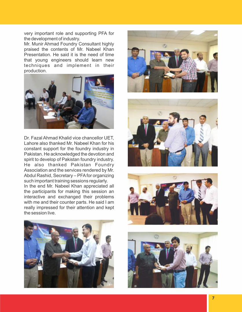
very important role and supporting PFA for the development of industry.Mr. Munir Ahmad Foundry Consultant highly praised the contents of Mr. Nabeel Khan Presentation. He said it is the need of time that young engineers should learn new techniques and implement in their production.
Dr. Fazal Ahmad Khalid vice chancellor UET, Lahore also thanked Mr. Nabeel Khan for his constant support for the foundry industry in Pakistan. He acknowledged the devotion and spirit to develop of Pakistan foundry industry. He also thanked Pakistan Foundry Association and the services rendered by Mr. Abdul Rashid, Secretary – PFA for organizing such important training sessions regularly. In the end Mr. Nabeel Khan appreciated all the participants for making this session an interactive and exchanged their problems with me and their counter parts. He said I am really impressed for their attention and kept the session live.
7


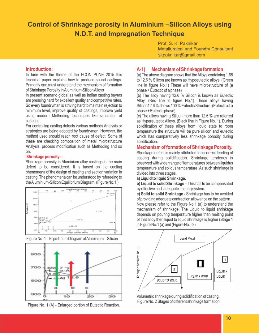
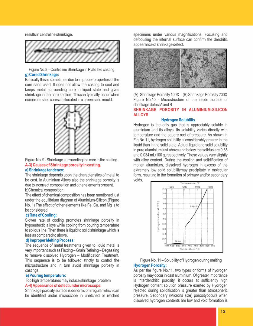
A-1) Mechanism of Shrinkage formation(a) The above diagram shows that the Alloys containing 1.65 to 12.6 % Silicon are known as Hypoeutectic alloys. (Green line in figure No.1) These will have microstructure of (a phase + Eutectic of a phase) (b) The alloy having 12.6 % Silicon is known as Eutectic Alloy. (Red line in figure No.1) These alloys having Silicon12.6 % shows 100 % Eutectic Structure. (Eutectic of a phase + Eutectic phase) (c) The alloys having Silicon more than 12.6 % are referred as Hypereutectic Alloys. (Black line in Figure No. 1). During solidification of these alloys from liquid state to room temperature the structure will be pure silicon and eutectic which has comparatively less shrinkage porosity during solidification.
Mechanism of formation of Shrinkage Porosity.Shrinkage defect is mainly attributed to incorrect feeding of casting during solidification. Shrinkage tendency is observed with wider range of temperatures between liquidus temperature and solidus temperature. As such shrinkage is divided into three stages.a) Liquid to liquid Shrinkage.b) Liquid to solid Shrinkage – This has to be compensated by effective and adequate risering system. c) Solid to solid Shrinkage - Shrinkage has to be avoided of providing adequate contraction allowance on the pattern.Now please refer to the Figure No.1 (a) to understand the mechanism of shrinkage. The Liquid to liquid shrinkage depends on pouring temperature higher than melting point of that alloy then liquid to liquid shrinkage is higher (Stage 1 in Figure No.1 (a) and (Figure No. - 2)
.
Volumetric shrinkage during solidification of casting. Figure No. 2 Stages of different shrinkage formation
Introduction:In tune with the theme of the FCON PUNE 2015 this technical paper explains how to produce sound castings. Primarily one must understand the mechanism of formation of Shrinkage Porosity in Aluminium-Silicon Alloys In present scenario global as well as Indian casting buyers are pressing hard for excellent quality and competitive rates. So every foundryman is striving hard to maintain rejection to minimum level, improve quality of castings, improve yield using modern Methoding techniques like simulation of castings.For controlling casting defects various methods Analysis or strategies are being adopted by foundrymen. However, the method used should reach root cause of defect. Some of these are checking composition of metal microstructure Analysis, process modification such as Methoding and so on. Shrinkage porosity –Shrinkage porosity in Aluminium alloy castings is the main defect to be considered. It is based on the cooling phenomena of the design of casting and section variation in casting. The phenomena can be understood by refereeing to the Aluminium-Silicon Equilibrium Diagram. (Figure No.1.)
Figure No. 1 – Equilibrium Diagram of Aluminium – Silicon
10
Control of Shrinkage porosity in Aluminium –Silicon Alloys using
N.D.T. and Impregnation Technique
Prof. S. K. PaknikarMetallurgical and Foundry Consultant
Figure No. 1 (A) - Enlarged portion of Eutectic Reaction.

During stage 1 in figure No. 2 there is Liquid to liquid shrinkage. This will be higher if the temperature of pouring is too higher then there is higher shrinkage.During stage 2 in figure No. 2 there is Liquid + Solid phases and there is shrinkage which has to be avoided by proper risering system.Now Stage 3 in figure 2 there is solid to solid shrinkage or contraction which has to be compensated by correct contraction allowance to get correct dimensions of casting. A-2) Types of Shrinkage Defects: This classification is based on location of shrinkage defect.a) Open or External Shrinkage – Normally it is open on the top surface of casting in cope box. This can be eliminated by proper directional solidification and proper location of risers.
(A) (B)Figure No. 3 (A) & (B) - Open or External Shrinkage.b) Internal or blind shrinkage: This is revealed only after machining. Sometimes it is deep, which remains inside even after machining. This type of shrinkage is very dangerous and which can be detected only by radiographic inspection. The internal defects are opened after machining. Refer Figure 6 (B).
(A) (B) Figure 4 (A) & (B) - Internal or Blind Shrinkagec) Corner Shrinkage: This type of shrinkage occurs at sharp corners in casting without any fillet radius. Due to sharp corner “Hot spot” is formed due to insufficient rate of heat transfer from mould corner, which leads to corner shrinkage. Obviously it can be avoided by providing sufficient fillet radius. Sometimes it is also mistaken as Hot Tear.
(A)
(B) © Figure No. 5 – Shrinkage at corner.(A) Schismatic Diagram (B) Change in design (C) Shrinkage Defectd) Shrinkage at section variation: This can be prevented by gradual changes in sections in casting design if possible. .
Figure No. 6 (A) & (B) - Shrinkage at section variatione) Isolated heavy sections in castings. Isolated heavy sections cannot be fed properly even if due care is taken while selecting parting line to ensure directional solidification.
Figure No.7 - Shrinkage at the Isolated Heavy Sections.f) Centreline shrinkage: This is observed in plate like castings. Solidification starts from mould walls from all sides while metal at the centre remains liquid which then cannot be fed and this
11
results in centreline shrinkage.
Figure No.8 – Centreline Shrinkage in Plate like casting.g) Cored Shrinkage: Basically this is sometimes due to improper properties of the core sand used. It does not allow the casting to cool and keeps metal surrounding core in liquid state and gives shrinkage in the core section. Thiscan typically occur when numerous shell cores are located in a green sand mould.
Figure No. 9 - Shrinkage surrounding the core in the casting.A-3) Causes of Shrinkage porosity in casting.a) Shrinkage tendency: The shrinkage depends upon the characteristics of metal to be cast. In Aluminium Alloys also the shrinkage porosity is due to incorrect composition and other elements present. b)Chemical composition:The effect of chemical composition has been mentioned just under the equilibrium diagram of Aluminium-Silicon.(Figure No. 1) The effect of other elements like Fe, Cu, and Mg is to be considered. c) Rate of Cooling:Slower rate of cooling promotes shrinkage porosity in hypoeutectic alloys while cooling from pouring temperature to solidus line. Then there is liquid to solid shrinkage which is less as compared to above. d) Improper Melting Process:The sequence of metal treatments given to liquid metal is very important such as Fluxing – Grain Refining – Degassing to remove dissolved Hydrogen – Modification Treatment. This sequence is to be followed strictly to control the microstructure and in turn avoid shrinkage porosity in castings. e) Pouring temperature: Too high temperatures may induce shrinkage problemA-4) Appearance of defect under microscope. Shrinkage porosity surface is dendritic or irregular which can be identified under microscope in unetched or retched
specimens under various magnifications. Focusing and defocusing the internal surface can confirm the dendritic appearance of shrinkage defect.
(A) Shrinkage Porosity 100X (B) Shrinkage Porosity 200XFigure No.10 - Microstructure of the inside surface of shrinkage defect A and BSHRINKAGE POROSITY IN ALUMINIUM-SILICON ALLOYS Hydrogen SolubilityHydrogen is the only gas that is appreciably soluble in aluminium and its alloys. Its solubility varies directly with temperature and the square root of pressure. As shown in Fig.No.11, hydrogen solubility is considerably greater in the liquid than in the solid state. Actual liquid and solid solubility in pure aluminium just above and below the solidus are 0.65 and 0.034 mL/100 g, respectively. These values vary slightly with alloy content. During the cooling and solidification of molten aluminium, dissolved hydrogen in excess of the extremely low solid solubilitymay precipitate in molecular form, resulting in the formation of primary and/or secondary voids.
Figure No. 11 – Solubility of Hydrogen during meltingHydrogen Porosity:As per the figure No.11, two types or forms of hydrogen porosity may occur in cast aluminium. Of greater importance is interdendritic porosity, it occurs at sufficiently high Hydrogen content solution pressure exerted by Hydrogen rejected during solidification is greater than atmospheric pressure. Secondary (Microns size) porosityoccurs when dissolved hydrogen contents are low and void formation is
12
characteristically sub critical.Finely distributed hydrogen porosity may not always be undesirable. Hydrogen precipitation may alter the form and distribution of shrinkage porosity in poorly fed parts or part sections. Shrinkage is generally more harmful to casting properties. In isolated cases, hydrogen may actually be intentionally introduced and controlled in specific concentrations compatible with the application requirements of the casting in order to promote superficial soundness.Nevertheless, hydrogen porosity adversely affects mechanical properties in a manner that varies with the alloy. Hydrogen Removal: Dissolved hydrogen levels can be reduced by a number of methods, the most important of which is fluxing with dry, chemically pure gas like Nitrogen, Argon, Chlorine, and Freon. Compounds such as hexachloroethane are in common use; these compounds dissociate at molten metal temperatures facilitate generation of fluxing gas. Gas fluxing reduces the dissolved hydrogen content of molten aluminium by partial pressure diffusion. The use of reactive gases such as Chlorine improves the rate of degassing by altering the gas/metal interface to improve diffusion kinetics.Holding the melt undisturbed for long periods of time at or near the liquidus also reduces hydrogen content to a level of alloy as the temperature-dependent liquid solubility.Evaluationof Molten Metal CleanlinessThere are several means to evaluate molten metal cleanliness that the foundry can employ either in process development or as ongoing production process monitoring. The most common practical and technical methodologies are the following:(1) Reduced pressure test;(2) Actual hydrogen measurement Reduced Pressure TestThis is the most common method which many non-die casting foundries use today and it is becoming increasingly prevalent in die casting and a simple means of evaluating metal quality. It provides a semi-quantitative measure of overall melt cleanliness, as well as ‘hydrogen gas’ content, in the following manner. It is well recognized that inclusions promotes hydrogen porosity. In the reduced pressure test, the presence of inclusions will assist any hydrogen present to develop an exaggerated visualization of pores, evident when the sample is sectioned after solidification. After the sample has been collected and allowed to solidify under reduced pressure, the specific gravity of the sample can be determined by Archimedes principle to give an apparent density. This can then be compared to theoretical density, and relative to samples prepared without reduced pressure, an estimate of hydrogen content can be determined.
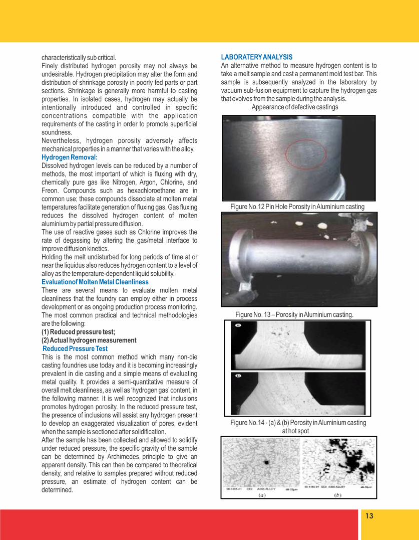
LABORATERY ANALYSISAn alternative method to measure hydrogen content is to take a melt sample and cast a permanent mold test bar. This sample is subsequently analyzed in the laboratory by vacuum sub-fusion equipment to capture the hydrogen gas that evolves from the sample during the analysis. Appearance of defective castings
Figure No.12 Pin Hole Porosity in Aluminium casting
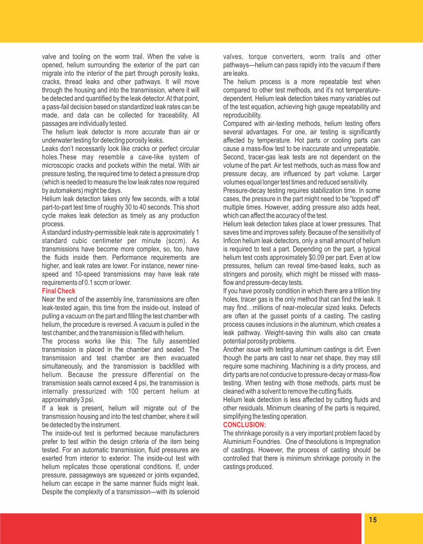
Figure No. 13 – Porosity in Aluminium casting.
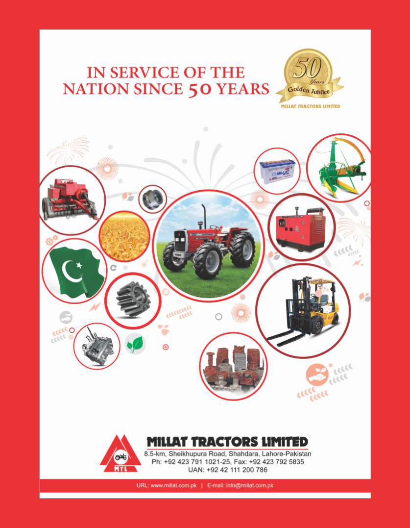
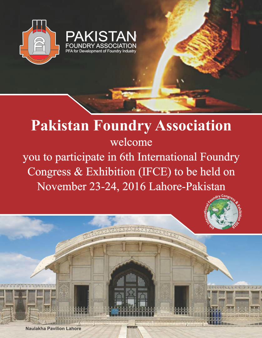
Figure No.14 - (a) & (b) Porosity in Aluminium casting at hot spot
13

Figure No.15 (a) Shrinkage at the surface (b) Shrinkage at centreShrinkage forms due to different cooling rates at surface& at centreUSE OF N.D.T. TECHNOLOGY FOR DETECTING POROSITY IN CASTINGSFigure No. 16 – (A) & (B) (C) Die Penetration test N.D.T. for internal shrinkage porosity
(A)
(B)
©
As shown in above figure it is indicated that if the peaks are very close,castings are not acceptable.
On –line Ultrasonic Test during production of castings: On line Ultrasonic Testing is used in some plants to access the size and continuity of the porosity in Aluminium Alloys. The Figure No.17 shows the on line testing of castings more peaks in graph indicate possibility of interconnected shrinkage porosity. If this is the condition thenthe level of porosity may be 5 to 6 and due to interconnection the leakage problem will be there. “X” rays or “Gamma rays” is determined by the average wall thickness of casting. “Gamma rays are used for thick sections while “X rays” are used for other sections.LEAKAGE TESTING AND PENETRATION TESTING OF CASTINGThe leakage in components like Aluminium Engine of automobiles is very dangerous so it should be thoroughly checked before dispatch. The castings are repaired by impregnation which will be explained during the Techmart followed after this presentation.There will be some indication of leakage from the measurement of hydrogen in the metal and ultrasonic testing of castings.Leak Testing Aluminum Castings
Figure No. 18. – Leakage Testing Machine for castings.Next to the engine, the automatic transmission may be the most important subsystem of an automobile. It plays a key role in handling, performance and fuel economy.Testing Technology -After casting and machining, transmission housings are robotically loaded into the test chamber. Inside the chamber, the “worm trail” and other cavities are sealed with a part-specific fixture machined to tight dimensional tolerances.Once the part has been clamped and sealed, the chamber is evacuated. Helium is then injected into the enclosure, which is connected to a helium leak detector. Fans agitate the air inside the enclosure to create a uniform mixture of 1 percent helium and air. The leak detector is connected to the test part through a
14
Figure No. 17 - On line N.D.T. for internal shrinkage defects.
15
valve and tooling on the worm trail. When the valve is opened, helium surrounding the exterior of the part can migrate into the interior of the part through porosity leaks, cracks, thread leaks and other pathways. It will move through the housing and into the transmission, where it will be detected and quantified by the leak detector. At that point, a pass-fail decision based on standardized leak rates can be made, and data can be collected for traceability. All passages are individually tested.The helium leak detector is more accurate than air or underwater testing for detecting porosity leaks. Leaks don’t necessarily look like cracks or perfect circular holes.These may resemble a cave-like system of microscopic cracks and pockets within the metal. With air pressure testing, the required time to detect a pressure drop (which is needed to measure the low leak rates now required by automakers) might be days.Helium leak detection takes only few seconds, with a total part-to-part test time of roughly 30 to 40 seconds. This short cycle makes leak detection as timely as any production process.A standard industry-permissible leak rate is approximately 1 standard cubic centimeter per minute (sccm). As transmissions have become more complex, so, too, have the fluids inside them. Performance requirements are higher, and leak rates are lower. For instance, newer nine-speed and 10-speed transmissions may have leak rate requirements of 0.1 sccm or lower.Final CheckNear the end of the assembly line, transmissions are often leak-tested again, this time from the inside-out. Instead of pulling a vacuum on the part and filling the test chamber with helium, the procedure is reversed. A vacuum is pulled in the test chamber, and the transmission is filled with helium.The process works like this: The fully assembled transmission is placed in the chamber and sealed. The transmission and test chamber are then evacuated simultaneously, and the transmission is backfilled with helium. Because the pressure differential on the transmission seals cannot exceed 4 psi, the transmission is internally pressurized with 100 percent helium at approximately 3 psi.If a leak is present, helium will migrate out of the transmission housing and into the test chamber, where it will be detected by the instrument.The inside-out test is performed because manufacturers prefer to test within the design criteria of the item being tested. For an automatic transmission, fluid pressures are exerted from interior to exterior. The inside-out test with helium replicates those operational conditions. If, under pressure, passageways are squeezed or joints expanded, helium can escape in the same manner fluids might leak. Despite the complexity of a transmission—with its solenoid
valves, torque converters, worm trails and other pathways—helium can pass rapidly into the vacuum if there are leaks.The helium process is a more repeatable test when compared to other test methods, and it’s not temperature-dependent. Helium leak detection takes many variables out of the test equation, achieving high gauge repeatability and reproducibility.Compared with air-testing methods, helium testing offers several advantages. For one, air testing is significantly affected by temperature. Hot parts or cooling parts can cause a mass-flow test to be inaccurate and unrepeatable. Second, tracer-gas leak tests are not dependent on the volume of the part. Air test methods, such as mass flow and pressure decay, are influenced by part volume. Larger volumes equal longer test times and reduced sensitivity.Pressure-decay testing requires stabilization time. In some cases, the pressure in the part might need to be “topped off” multiple times. However, adding pressure also adds heat, which can affect the accuracy of the test.Helium leak detection takes place at lower pressures. That saves time and improves safety. Because of the sensitivity of Inficon helium leak detectors, only a small amount of helium is required to test a part. Depending on the part, a typical helium test costs approximately $0.09 per part. Even at low pressures, helium can reveal time-based leaks, such as stringers and porosity, which might be missed with mass-flow and pressure-decay tests.If you have porosity condition in which there are a trillion tiny holes, tracer gas is the only method that can find the leak. It may find…millions of near-molecular sized leaks. Defects are often at the gusset points of a casting. The casting process causes inclusions in the aluminum, which creates a leak pathway. Weight-saving thin walls also can create potential porosity problems.Another issue with testing aluminum castings is dirt. Even though the parts are cast to near net shape, they may still require some machining. Machining is a dirty process, and dirty parts are not conducive to pressure-decay or mass-flow testing. When testing with those methods, parts must be cleaned with a solvent to remove the cutting fluids.Helium leak detection is less affected by cutting fluids and other residuals. Minimum cleaning of the parts is required, simplifying the testing operation.CONCLUSION:The shrinkage porosity is a very important problem faced by Aluminium Foundries. One of thesolutions is Impregnation of castings. However, the process of casting should be controlled that there is minimum shrinkage porosity in the castings produced.

Naulakha Pavilion Lahore

JIT or total productive maintenance, even
production, SMED etc. The tool used for
continuous improvement (Kaizen) include
application of DMIAC cycle that is discussed in
the next section. Trust and empowerment is a
very important subject of modern management
philosophy and is equally emphasized and
applicable in Lean. Lean production enables
integration of various tools in the production
system and supply chain to reduce costs,
improve quality, and decrease lead-time.
Use of Lean strategies are quite common in
foundries abroad and the statistical process
control fits into this regime perfectly. However, the
task of aligning the tools available in Lean with the
foundry operations is usually a challenge and
thus requires professional help.
The Lean manufacturing will help in reducing
waste, waiting time, and in balancing the
production line. The major benefit is high
productivity (quality, cost, and delivery) and
effective utilization of resources. We discuss
these points now.
1.Continuous Improvement We start by discussing the DMAIC cycle, which is
the backbone of the continuous improvement
under Lean philosophy also called the Kaizen.
We can apply the Lean concepts - elimination of
waste, continuous improvement and trust and
empowerment, to the foundry operations. In this
article, I will discuss some simple concepts of
Lean philosophy and their application in foundry
operations. In the subsequent articles more
conceptual topics related to Statistical Process
Control and their application shall be included.
The target audience for this article are foundries
run by professional and qualified Engineers keen
to improve competitiveness locally as well as in
exports and international markets. As a minimum,
these foundries have some system of
measurement, data collection, and analysis in
place. The competitive edge in the Foundry
business will come from technology up-gradation
and from operations excellence together, since
both of these are intertwined.
The fundamentals of Lean Philosophy are the
same across the manufacturing domain – in
foundries and other production / manufacturing
set-ups alike. Toyota Production System (TPS)
as shown below represent these:
Lean manufacturing focuses on elimination of
wastes – non-value added activities are
identified, using tools like Value Stream Mapping,
organization of workplace – 5S, Cellular
Manufacturing, or more complex topics such as
20
Productivity Improvement in Foundry through Lean
Ghazanfar Ullah KhanEx- Director Foundry in Shanghai [email protected]
DMAIC is the acronym of – Define, Measure,
Analyze, Improve, and Control and provides an
excellent scientific approach for improvement.
Define the goals of the improvement activity. At
the top level the goals will be the strategic
objectives of the organization, such as a higher
ROI or market share. At the operations level, a
goal might be to increase the throughput of a
production department. At the project level, goals
might be to reduce the defect level, and increase
throughput. Apply data mining methods to identify
potential improvement opportunities.
Measure the existing system. Establish valid and
reliable metrics to help monitor progress towards
the goal(s) defined at the previous step. Begin by
determining the current baseline. Use
exploratory and descriptive data analysis to help
you understand the data.
Analyze the system to identify ways to eliminate
the gap between the current performance of the
system or process and the desired goal. Apply
statistical tools to guide the analysis.
Improve the system. Be creative in finding new
ways to do things better, cheaper, or faster. Use
project management and other planning and
management tools to implement the new
approach. Use statistical methods to validate the
improvement.
Control the new system. Institutionalize the
improved system by modifying compensation
and incentive systems, policies, procedures,
MRP (Manufacturing Resource Planning),
budgets, operating instructions, and other
management systems. You may wish to utilize
systems such as ISO 9000 to assure that
documentation is correct.
Tinkering and tweaking here and there may give
you some respite, but the process approach is
essential for sustained results. Hence, it is
essential that proper application of DMAIC cycle
should be ensued using trained resources.
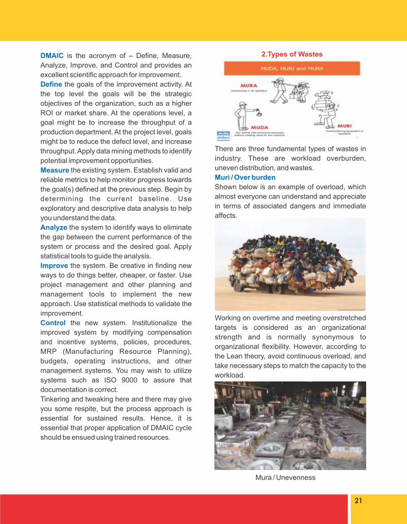
There are three fundamental types of wastes in
industry. These are workload overburden,
uneven distribution, and wastes.
Muri / Over burden
Shown below is an example of overload, which
almost everyone can understand and appreciate
in terms of associated dangers and immediate
affects.
Working on overtime and meeting overstretched
targets is considered as an organizational
strength and is normally synonymous to
organizational flexibility. However, according to
the Lean theory, avoid continuous overload, and
take necessary steps to match the capacity to the
workload.
Mura / Unevenness
21
2.Types of Wastes
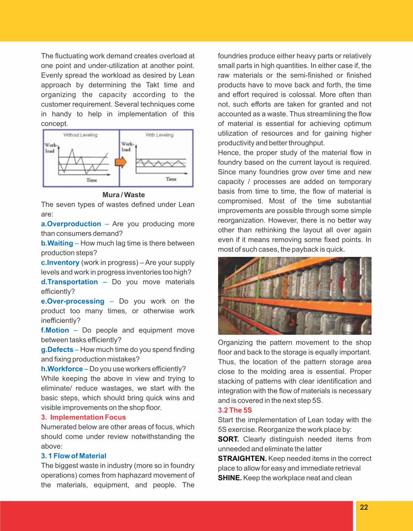
The fluctuating work demand creates overload at
one point and under-utilization at another point.
Evenly spread the workload as desired by Lean
approach by determining the Takt time and
organizing the capacity according to the
customer requirement. Several techniques come
in handy to help in implementation of this
concept.
Mura / Waste
The seven types of wastes defined under Lean
are:
a.Overproduction – Are you producing more
than consumers demand?
b.Waiting – How much lag time is there between
production steps?
c.Inventory (work in progress) – Are your supply
levels and work in progress inventories too high?
d.Transportation – Do you move materials
efficiently?
e.Over-processing – Do you work on the
product too many times, or otherwise work
inefficiently?
f.Motion – Do people and equipment move
between tasks efficiently?
g.Defects – How much time do you spend finding
and fixing production mistakes?
h.Workforce – Do you use workers efficiently?
While keeping the above in view and trying to
eliminate/ reduce wastages, we start with the
basic steps, which should bring quick wins and
visible improvements on the shop floor.
3. Implementation Focus
Numerated below are other areas of focus, which
should come under review notwithstanding the
above:
3. 1 Flow of Material
The biggest waste in industry (more so in foundry
operations) comes from haphazard movement of
the materials, equipment, and people. The
foundries produce either heavy parts or relatively
small parts in high quantities. In either case if, the
raw materials or the semi-finished or finished
products have to move back and forth, the time
and effort required is colossal. More often than
not, such efforts are taken for granted and not
accounted as a waste. Thus streamlining the flow
of material is essential for achieving optimum
utilization of resources and for gaining higher
productivity and better throughput.
Hence, the proper study of the material flow in
foundry based on the current layout is required.
Since many foundries grow over time and new
capacity / processes are added on temporary
basis from time to time, the flow of material is
compromised. Most of the time substantial
improvements are possible through some simple
reorganization. However, there is no better way
other than rethinking the layout all over again
even if it means removing some fixed points. In
most of such cases, the payback is quick.
Organizing the pattern movement to the shop
floor and back to the storage is equally important.
Thus, the location of the pattern storage area
close to the molding area is essential. Proper
stacking of patterns with clear identification and
integration with the flow of materials is necessary
and is covered in the next step 5S.
3.2 The 5S
Start the implementation of Lean today with the
5S exercise. Reorganize the work place by:
SORT. Clearly distinguish needed items from
unneeded and eliminate the latter
STRAIGHTEN. Keep needed items in the correct
place to allow for easy and immediate retrieval
SHINE. Keep the workplace neat and clean
22

STANDARDIZE. Make the above 3 steps as a
part of regular exercise
SUSTAIN. Include the above steps in a SOP and
implement the SOP.
5S will improve speed of operations and will
Ÿ make space available for other use,
Ÿ make workplace safer,
Ÿ provide visual control over operations
5S philosophy seems simple but its proper
implementation requires training, which is often
quite beneficial.
Foundries are normally dark and dingy and this is
accepted as a norm. Shift this paradigm as more
and more clean and organized foundries can be
seen in the foundry world.
3.3 VSM
Trained engineers carry out the Value Stream
Mapping by recording the events and their
duration in a set format thus segregating value
added and non-value added activities. Non-value
added time results in higher intermediate
inventory, occupies shop floor space, and causes
delivery delays. Based on the findings of VSM a
new process is designed which should reduce /
eliminate the non-value added time, and lead to
reduction in intermediate inventory, shorter
throughput time, and improved ratio of value
added to total throughput time. The results of the
VSM are used for taking appropriate actions and
improvements.
3.4 Standardization of Operations.
Many foundries are built for handling one broad
category of material and for one or two production
processes. In such a case, it is easier to
standardize the operations. For example, cast
iron foundry is separate from a steel foundry.
Resin sand foundry is separate from green sand
foundry.
Similarly, jobbing foundries are separate from
series production. While the standardization in a
jobbing foundry needs more skills and analysis,
for series production focus on standardization is
easy.
The standardization of processes and the tools/
patterns and production aids do help in
productivity improvement. Basic mechanization
can help in improving the quality and reduction in
23

wastes. Standardization will help in optimization
and balancing of the production load.
3.5 Work Station Concept.
Although in a flow process the workstation
concept is sometimes difficult to fit, nevertheless,
wherever possible the workstation concept
should be preferred.
Design and construct the cell to:
Ÿ Implement a “U” shaped line to assure one-
way flow and maximize visibility,
Ÿ Provide a flexible layout to account for all
members of the production family,
Ÿ Decrease distance between operations and
integrating process operations wherever
possible for simplicity, minimizing both
transportation and production lot sizes,
integrate in point of use storage next to each
assembly operation.
Ÿ Minimize material handling by concentrating
on value added motion
Ÿ Establish replenishment procedures for point
of use storage using the A-B-C rule Assure the
personnel understand their role and are cross-
trained to use their skills at a variety of tasks
and work stations.
4.Solidification Simulation Software
Casting solidification software’s available in the
market provide an easy possibility of simulating
the solidification behavior of the metal and thus
provide quick feedback regarding the casting
results. With these simulations, the trial period
and effort is significantly reduced without
incurring any major expenditure in trial and error.
24
5. 3D measurement of castings with complex
geometry
It is possible to check the geometry of complex
castings w.r.t. the 3D drawings using
photographic techniques. With this technology,
the verification of the patterns is quick and the
conformance of the castings contours to the
drawing can be quickly verified.
General
Health, safety, and environment should be topics
of prime concern and hence shall be addressed in
the next articles along-with other improvement
schemes and statistical Process control tips.


INTRODUCTION FNB is a binder system comprising of two parts,
bothliquids. The resin, which is dark colored thin
liquid acts as binder for sand particles and the
catalyst or curing agent, is a solution of pure or
mixture of organic, inorganic or organo inorganic
acids in varying concentration.Introduced in world market in 1958 along with
PNB, it took long time at least in India to gain
popularity. Introduced in 1965 in world market, 3
Part Alkyd (nobake and semi bake) was the most
popular self-set in Indian Foundries in eighties.
PNB, which is also a two-part system, introduced
in Indian Foundries in early eighties could not
gain instant popularity mainly because of poor
bench life of mixed sand, irritating smell of
formaldehyde during mixing, limited storage life
of binder etc. However, in introductory stage, the
most important reason behind its nonacceptance
was that the system did not have sufficient
bench life of mixed sand suitable for use in batch
mixers particularly in summer and in big jobs,
which Alkyd could offer at ease. Introduction of continuous mixers (CSM) in Indian
Foundries in large scale in mid-eighties offered
Foundries option to think about enhanced
productivity and thus to go for faster setting
systems beyond Alkyd, for mold and
core making, as faster mixing and mold filling
cycles did allow to work Foundrymen with lower
bench life of mixed sand compared to Alkyd.
Binder manufacturers also started working on
other short falls namely reduction of fume level,
increase in shelf life, reduction of viscosity of
binder and few more. In another two or three
years, PNB was the first popular self-set
introduced in Indian market as binder for CSM to
produce flask- less molds in loop line with roll over
strip and option for reclamation by attrition. In the
process, alkyd started getting replaced by PNB
ABSTRACTLike Phenol (C H OH) and Urea {(NH ) C=O)}, 6 5 2 2
Furfuryl alcohol (C H OCH OH), a product of 4 3 2
agricultural origin is capable of polymerization
with Formaldehyde (H C = 0) under suitable PH 2
conditions. However, usable polymers, at least as
no bake for Foundry applications are obtained
only when the condensations are carried out in
association with Urea, Phenol or both. The series
of resins obtained, having Furan ring (C H O)4 4
in chains, at different PH conditions and varying
compositions are called Furan resins. These
resins (binders) and acids (catalysts) make a two
part no bake self-set system (popularly known as
FNB in foundry terms) like Alkyd, Phenolic no
bake (PNB), Urethane no bake (PUNB) and
Alkaline Phenolic no bake (APNB) for binding
sand particles for making moulds and cores in
metal casting Industries. With growth of Foundry
industry, several self-sets have been introduced
periodically for making molds and cores. Once
the most popular inorganic Binder i.e. Sodium
Silicate which make binder system with CO gas 2
or organic esters as curing agents has lost favor
of Foundrymen because of its inherent
drawbacks, main being poor de-coring property
and unsatisfactory casting finish. Other primitive
binders like cement, molasses and many
proprietory binders have largely been replaced
by modern organic binders mentioned above,
which meet requirements of faster productivity,
better out of box and handling strength of molds
and cores, rapid production cycle, better de-
coring property and eventually better casting
finish. This paper deals with evolution of Furan
from introductory to modern stage, its
advantages and disadvantages in comparison
with other self-sets and its present market
position and future trend, particularly in context to
foundries based in India and Middle East.
28
Modern Furan for Modern Castings
Dipak Ghosh
Forace polymers P Ltd, Haridwar, India
for making repetitive moulds.With success of PNB in CSM, some Indian
Foundries started working with FNB, application
of which match with PNB, mostly with imported
ones and on advice of foreign collaborators in
early eighties, when FNB was an established
system in European and American Foundries.
Experience was not sweet; as formulations
developed abroad did not meet conditions of
Indian Foundries, major being application
temperature and sand quality. Meanwhile, in mid-eighties, a new self-set called
Alkaline Phenolic no bake (APNB) two part
system was introduced in world market and also
almost simultaneously in Indian market. This
system with its unique three stage curing process
and absence of N – S & P was found to produce
castings of better quality than previous two. Steel
Foundries wanted to take advantage of absence
of said detrimental elements and CI foundries for
over all casting quality and cleaner foundry
environment.PUNB introduced in Indian Foundries in eighties
did not find mass application because of several
shortfalls, which include inferior working
environment and increased cost. Till date very
few Foundries in India are continuing with this
system. On positive side, it is fastest among self-
sets.Meanwhile APNB formulations got matured in
India and Foundries, particularly steel ones
started favoring this system in CSM with roll over
strip for flask less moulds apart from big boxed
moulds. Possibility for reclamation of used sand
and control on bench life and strip time of
mixed sand went in favor of the system over
Alkyd.FNB, with Indigenized formulations, when
reintroduced in Indian Foundries, started gaining
popularity by 2004. The FNB formulations
available with Indian manufacturers today are
most modern and are capable of meeting all
requirements of Foundrymen for all Ferrous and
Non-ferrous castings. Today’s FNB is altogether th
a different breed from those of 20 century and
one of the two most widely used selfsets
in Foundries, both Indian and abroad, other one
being APNB (Table-1) MATURING OF FNB FORMULATIONSWith FNB, bench life of mixed sand in Indian
Foundries in peak summer could be achieved up
to as high as 20 mts, making it suitable for making
giant moulds and cores for making heavy
castings for wind mills, turbine components etc.
In another extreme case, small moulds made with
FNB can be stripped as fast as within 10 minutes,
faster than other self-sets apart from PUNB. Low
addition level and possibility of using high ratio of
reclaimed: fresh sand (R: F) reduces gas content,
improves shakeout properties, reduces adverse
effect on environment, better economy and finally
sound castings in case of modern FNB. Low S
catalysts are available for SG iron castings. Safe
storage life of six months for binder makes FNB a
preferred one for export and use in hot
countries.FNB offers a series of formulations to be chosen
from. This is true for binders as well as catalysts.
Binder quality varies mainly depending on: ● Percentage of FA –usual range is 65 – 95% by
weight of total mass● Percentage of N – Usual range is Nil to 7% and
● Nature and % of other components present in
binderIn broad sense, more the FA content and lesser
the N content, better and costlier the product is. In Catalyst, the variables are:Ÿ Percentage purity of acidŸ Percentage S in system Ÿ Percentage P in system, if anySelectivity of grade of FNB is very much metal
specific. Whereas, in case of non-ferrous
castings, high N systems don’t have any adverse
effect on casting quality, cost being reduced
substantially, in case of steel castings, low or no -
N FNB is a must to get castings free from pinhole
defects.
29

30
MODERN FNB Reintroduction of Furan Binder System in Indian
Foundries at around 2004 started getting
recognition initially slowly and then rapidly. It took
time for Indian Foundrymen to forget bad
experience with Furan of eighties. In last few
years, growth of FNB market in India
has increased at same fast rate, if not more than
APNB. One of the reasons may be replacement
of PNB by FNB is much easier than by APNB due
to opposite PH reactions. Further, FNB has got
several unique advantages over APNB. These
are better flowability of mixed sand leading to
better mold compaction, better out of box and
handling strength of molds leading to rigidity and
less breakage, workability at much less binder
level, much better reclaimability of used sand,
faster productivity of molds and castings.Modern Furan offers excellent reclaim ability of
used sand, by single attrition; there are examples
of Foundries in India where reclaimability level is
as high as 85% and addition level is 0.8: 30 – 50 in
system sand of 85: 15. No other Binder system is
workable at this low binder addition level. Further, modern FNB can work over a wide
room/sand temperature, which no other modern
self sets can probably match. FNB has been
found practically to work in temperature range of
near zero to 55°C. In case of ferrous metals, - N content in the
system plays an important role dictating its
selection on metal composition. It is a well
documented fact that N in elemental form is
dissolved in molten ferrous metal causing
porosity in castings. Severity of effect is more in
steel than CI castings. In CI castings also, section
thickness of casting and its geometry decides the
maximum allowed N in the FNB formulation to be
allowed.In general, maximum allowed - N content in FNB
for various metals are as follows:
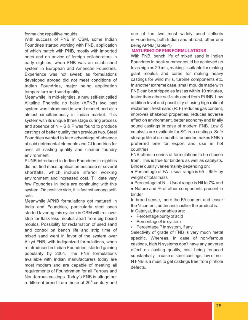
It is more practical to go by N content of molding
sand rather than that of Binder. Recommended
allowable maximum N content in molding sand
for different ferrous castings are as follows:
There is no chemistry behind difference in upper
limit of % recommended - N content in CI and SG
Iron. One answer may be the difference in
allowance for soundness of casting between SG
and CI; the former can be tested 100% for internal
defects by ultrasound method but not later.Again, not percent of - N, but its form in molding
sand is of more importance for causing pinhole
defects in ferrous castings. Nitrogen bearing
elements, which decompose to produce
elemental N, are utmost risky as the same is
dissolved easily in liquid metal to give porosity
defects. Ammonia cal Nitrogen comes under this
category.One classical example of above phenomenon is
that PUNB, although it has N in structure of co-
binder are being successfully used in steel
Foundries, whereas N bearing FNB, shell system
and hot box pose easy threat of pinhole
formation.CONCLUSIONAlthough introduced in 1958 along with PNB as
first synthetic binder systems in world market,
FNB took long time to reach Indian Foundries, in
fact much later than Alkyd and PNB.Today’s FNB (modern) formulations in India are
not only capable of meeting all the requirements
of Indian foundry men, both ferrous and non-
ferrous, but also competing with global suppliers
in Indian and Middle East market. Further, it can
be said with confidence that modern FNB in India
are not inferior to any of the formulations
available globally.Modern FNB in India is a complete foundry bindercompatible with most of sand being used
commercially and climatic conditions.
31
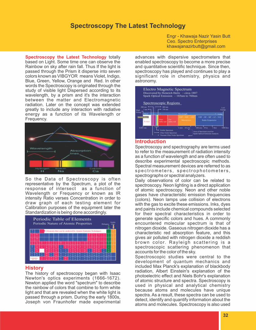
advances with dispersive spectrometers that enabled spectroscopy to become a more precise and quantitative scientific technique. Since then, spectroscopy has played and continues to play a significant role in chemistry, physics and astronomy.
IntroductionSpectroscopy and spectrography are terms used to refer to the measurement of radiation intensity as a function of wavelength and are often used to describe experimental spectroscopic methods. Spectral measurement devices are referred to as s p e c t r o m e t e r s , s p e c t r o p h o t o m e t e r s , spectrographs or spectral analyzers.Daily observations of color can be related to spectroscopy. Neon lighting is a direct application of atomic spectroscopy. Neon and other noble gases have characteristic emission frequencies (colors). Neon lamps use collision of electrons with the gas to excite these emissions. Inks, dyes and paints include chemical compounds selected for their spectral characteristics in order to generate specific colors and hues. A commonly encountered molecular spectrum is that of nitrogen dioxide. Gaseous nitrogen dioxide has a characteristic red absorption feature, and this gives air polluted with nitrogen dioxide a reddish brown co lo r. Ray le igh sca t te r ing i s a spectroscopic scattering phenomenon that accounts for the color of the sky.Spectroscopic studies were central to the development of quantum mechanics and included Max Planck's explanation of blackbody radiation, Albert Einstein's explanation of the photoelectric effect and Niels Bohr's explanation of atomic structure and spectra. Spectroscopy is used in physical and analytical chemistry because atoms and molecules have unique spectra. As a result, these spectra can be used to detect, identify and quantify information about the atoms and molecules. Spectroscopy is also used
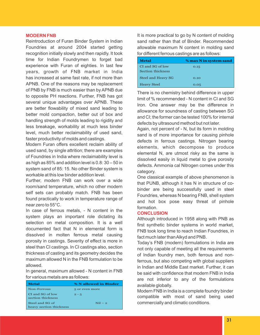
Spectroscopy the Latest Technology totally based on Light. Some time one can observe the Rainbow on sky after rain fall. Thus If the light is passed through the Prism it disperse into seven colors known as VIBGYOR means Violet, Indigo, Blue, Green, Yellow, Orange and Red. In other words the Spectroscopy is originated through the study of visible light Dispersed according to its wavelength, by a prism and it's the interaction between the matter and Electromagnetic radiation. Later on the concept was extended greatly to include any interaction with radiative energy as a function of its Wavelength or Frequency.
So the Data of Spect roscopy is o f ten representative by the Spectrum, a plot of the response of intersect as a function of Wavelength or Frequency or known as IR intensity Ratio verses Concentration in order to draw graph of each testing element for Calibration purposes of the equipment later the Standardization is being done accordingly.
HistoryThe history of spectroscopy began with Isaac Newton's optics experiments (1666-1672). Newton applied the word "spectrum" to describe the rainbow of colors that combine to form white light and that are revealed when the white light is passed through a prism. During the early 1800s, Joseph von Fraunhofer made experimental
32
Spectroscopy The Latest Technology
Engr - Khawaja Nazir Yasin Butt Ceo. Spectro [email protected]

in astronomy and remote sensing on earth. Most research telescopes have spectrographs. The measured spectra are used to determine the chemical composition and physical properties of astronomical objects (such as their temperature and velocity).In spectroscopy the Periodic Table used for the different Elements is based on Wavelength/ intensity of Light instead of Atomic weight or Atomic Number.The major difference of Spectrograph and Spectrometer is where you have known focal length between the Grating and detectors or PMTs it is known as Spectrometer. It may be 1m, 0.5m or lower one.
Basic TheoryOne of the central concepts in spectroscopy is a resonance and its corresponding resonant frequency. Resonances were first characterized in mechanical systems such as pendulums. Mechanical systems that vibrate or oscillate will experience large amplitude oscillations when they are driven at their resonant frequency. A plot of amplitude vs. excitation frequency will have a peak centered at the resonance frequency. This plot is one type of spectrum, with the peak often referred to as a spectral line, and most spectral lines have a similar appearance.In quantum mechanical systems, the analogous resonance is a coupling of two quantum mechanical stationary states of one system, such as an atom, via an oscillatory source of energy such as a photon. The coupling of the two states is strongest when the energy of the source matches the energy difference between the two states. The energy of a photon is related to its frequency by where is Planck's constant, and so a spectrum of the system response vs. photon frequency will peak at the resonant frequency or energy. Particles such as electrons and neutrons have a comparable relationship, the de Broglie relations, between their kinetic energy and their wavelength and frequency and therefore can also excite resonant interactions.Spectra of atoms and molecules often consist of a series of spectral lines, each one representing a resonance between two different quantum states. The explanation of these series, and the spectral patterns associated with them, were one of the experimental enigmas that drove the development and acceptance of quantum mechanics. The hydrogen spectral series in particular was first successfully explained by the Rutherford-Bohr quantum model of the hydrogen atom. In some cases spectral lines are well separated and distinguishable, but spectral lines
can also overlap and appear to be a single transition if the density of energy states is high enough. Named series of lines include the principal, sharp, diffuse and fundamental series.Spectroscopy is a sufficiently broad field that many sub-disciplines exist, each with numerous implementations of specific spectroscopic techniques. The various implementations and techniques can be classified in several ways.Type of Radiative EnergyTypes of spectroscopy are distinguished by the type of radiative energy involved in the interaction. In many applications, the spectrum is determined by measuring changes in the intensity or frequency of this energy. The types of radiative energy studied include:l Electromagnetic radiation was the first source of energy used for spectroscopic studies. Techniques that employ electromagnetic radiation are typically classif ied by the wavelength region of the spectrum and include microwave, terahertz, infrared, near infrared, visible and ultraviolet, x-ray and gamma spectroscopy.l Particles, due to their de Broglie wavelength, can also be a source of radiative energy and both electrons and neutronsare commonly used. For a particle, its kinetic energy determines its wavelength.l Acoustic spectroscopy involves radiated pressure waves.l Mechanical methods can be employed to impart radiating energy, similar to acoustic waves, to solid materials.Type of MaterialSpectroscopic studies are designed so that the radiant energy interacts with specific types of matter.AtomsAtomic spectroscopy was the first application of spectroscopy developed. Atomic absorption spectroscopy (AAS) and atomic emission spectroscopy (AES) involve visible and ultraviolet light. These absorptions and emissions, often referred to as atomic spectral lines, are due to electronic transitions of outer shell electrons as they rise and fall from one electron orbit to another. Atoms also have distinct x-ray spectra that are attributable to the excitation of inner shell electrons to excited states.
33

Atoms of different elements have distinct spectra and therefore atomic spectroscopy allows for the identification and quantization of a sample's elemental composition. Robert Bunsen and Gustav Kirchhoff discovered new elements by observing their emission spectra. Atomic absorption lines are observed in the solar spectrum and referred to as Fraunhofer lines after their discoverer. A comprehensive explanation of the hydrogen spectrum was an early success of quantum mechanics and explained the Lamb shift observed in the hydrogen spectrum led to the development of quantum electrodynamics.
Modern implementations of atomic spectroscopy for studying visible and ultraviolet transitions include flame emission spectroscopy, inductively coupled plasma atomic emission spectroscopy, glow discharge spectroscopy, microwave induced plasma spectroscopy, and spark or arc emission spectroscopy. Techniques for studying x-ray spectra include X-ray spectroscopy and X-ray fluorescence (XRF).
MoleculesThe combination of atoms into molecules leads to the creation of unique types of energetic states and therefore unique spectra of the transitions between these states. Molecular spectra can be obtained due to electron spin states (electron paramagnetic resonance), molecular rotations, molecular vibration and electronic states.
Rotations are collective motions of the atomic nuclei and typically lead to spectra in the microwave and millimeter-wave spectral regions; rotat ional spectroscopy and microwave spectroscopy are synonymous. Vibrations are relative motions of the atomic nuclei and are s tud ied by bo th i n f r a red and Raman spectroscopy. Electronic excitations are studied using visible and ultraviolet spectroscopy as well as fluorescence spectroscopy.Studies in molecular spectroscopy led to the development of the first maser and contributed to the subsequent development of the laser.Crystals and extended materialsThe combination of atoms or molecules into crystals or other extended forms leads to the creation of additional energetic states. These states are numerous and therefore have a high density of states. This high density often makes the spectra weaker and less distinct, i.e., broader. For instance, blackbody radiation is due to the thermal motions of atoms and molecules within a material. Acoustic and mechanical responses are due to collective motions as well. Pure crystals, though, can have distinct spectral transitions, and the crystal arrangement also has an effect on the observed molecular spectra. The regular lattice structure of crystals also scatters x-rays, e l e c t r o n s o r n e u t r o n s a l l o w i n g f o r crystallographic studies.NucleiNuclei also have distinct energy states that are widely separated and lead to gamma ray spectra. Distinct nuclear spin states can have their energy separated by a magnetic field, and this allows for NMR spectroscopy.
Other Types Other types of spectroscopy are distinguished by specific applications or implementations:l Acoustic resonance spectroscopy is based on sound waves primarily in the audible and ultrasonic regionsl Auger spectroscopy is a method used to study surfaces of materials on a micro-scale. It is often used in connection with electron microscopy.l Cavity ring down spectroscopyl Circular Dichroism spectroscopyl Coherent anti-Stokes Raman spectroscopy (CARS) is a recent technique that has high sensitivity and powerful applications for in vivo spectroscopy and imaging. l Cold vapor atomic fluorescence spectroscopylCorrelation spectroscopy encompasses several types of two-dimensional NMR spectroscopy.l Deep-level transient spectroscopy measures
34
concentration and analyzes parameters of electrically active defects in semiconducting materialsl Dual polarization interferometry measures the real and imaginary components of the complex refractive indexl Electron phenomenological spectroscopy measures physicochemical properties and characteristics of electronic structure of mult icomponent and complex molecular systems.l EPR spectroscopyl Force spectroscopyl Fourier transform spectroscopy is an efficient method for processing spectra data obtained using interferometers. Fourier transform infrared s p e c t r o s c o p y ( F T I R ) i s a c o m m o n implementation of infrared spectroscopy. NMR also employs Fourier transforms.l Hadron spectroscopy studies the energy/mass spectrum of hadrons according to spin, parity, and o ther par t i c le p roper t ies . Baryon spectroscopy and meson spectroscopy are both types of hadron spectroscopy.l Hyperspectral imaging is a method to create a complete picture of the environment or various objects, each pixel containing a full visible, VNIR, NIR, or infrared spectrum.l Inelastic electron tunneling spectroscopy (IETS) uses the changes in current due to inelastic electron-vibration interaction at specific energies that can also measure optically forbidden transitions.l Inelastic neutron scattering is similar to Raman spectroscopy, but uses neutrons instead of photons.l Laser-Induced Breakdown Spectroscopy (LIBS), also called Laser-induced plasma spectrometry (LIPS)l Laser spectroscopy uses tunable lasers and other types of coherent emission sources, such as optical parametric oscillators, for selective excitation of atomic or molecular species.l Mass spectroscopy is an historical term used to r e f e r t o m a s s s p e c t r o m e t r y. C u r r e n t recommendations are to use the latter term. Use of the term mass spectroscopy originated in the use of phosphor screens to detect ions.l Mössbauer spectroscopy probes the properties of specific isotopic nuclei in different atomic environments by analyzing the resonant absorption of gamma-rays. l Neutron spin echo spectroscopy measures internal dynamics in proteins and other soft matter systemsl Photoacoustic spectroscopy measures the
sound waves produced upon the absorption of radiation.l Photoemission spectroscopyl Photothermal spectroscopy measures heat evolved upon absorption of radiation.l Pump-probe spectroscopy can use ultrafast laser pulses to measure reaction intermediates in the femtosecond timescale.l Raman optical activity spectroscopy exploits Raman scattering and optical activity effects to reveal detailed information on chiral centers in molecules.l Raman spectroscopyl Saturated spectroscopyl Scanning tunneling spectroscopyl Time-resolved spectroscopy measures the decay rate(s) of excited states using various spectroscopic methods and Time-Stretch Spectroscopyl Thermal infrared spectroscopy measures thermal radiation emitted from materials and surfaces and is used to determine the type of bonds present in a sample as well as their lattice environment. The techniques are widely used by organic chemists, mineralogists, and planetary scientists.l Ultraviolet photoelectron spectroscopy (UPS)l Video spectroscopy and Vibrational dichroism spectroscopyl X-ray photoelectron spectroscopy (XPS)Normally for testing of Metals Optical Emission Spectrometers are being utilized all over the world. Old version comprises of Vacuum System with insertion of PMTs Tubes for each element which are larger in size whereas the new and latest Spectrometers are without Vacuum System and instead of PMTs DC Detectors are being utilized which are more economical, compact in size, Energy saver and price wise almost half of the old version similarly the cost of analysis per specimen is one tenth as compared to old version.
Referencesl John M. Chalmers; Peter Griffiths, eds. (2006). Handbook of Vibrational Spectroscopy. New York: Wiley. doi:10.1002/0470027320. ISBN 0-471-98847-2. 5 Volume Set.l Jerry Workman; Art Springsteen, eds. (1998). Applied Spectroscopy. Boston: Academic Press. ISBN 978-0-08-052749-9.
35