Film Capacitors - Power Electronic Capacitors - MKP DC ... · Film Capacitors B2568* Power...
25
Film Capacitors Power Electronic Capacitors Series/Type: MKP DC Ordering code: B2568* Date: March 2019 Version: 1 TDK Electronics AG 2019. Reproduction, publication and dissemination of this publication, enclosures hereto and the information contained therein without TDK Electronics' prior express consent is prohibited.
Transcript of Film Capacitors - Power Electronic Capacitors - MKP DC ... · Film Capacitors B2568* Power...
Film Capacitors
Power Electronic Capacitors
Series/Type: MKP DC Ordering code: B2568*
Date: March 2019 Version: 1
TDK Electronics AG 2019. Reproduction, publication and dissemination of this publication, enclosures hereto and the information contained therein without TDK Electronics' prior express consent is prohibited.
Film Capacitors B2568*
Power Electronic Capacitors MKP DC
CAP PW PD March 2019
Please read Cautions and warnings and Page 2 of 25 Important notes at the end of this document.
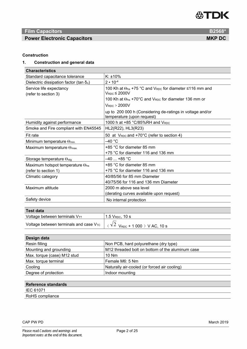
Construction
1. Construction and general data
Characteristics
Standard capacitance tolerance K: ±10%
Dielectric dissipation factor (tan δo) 2 • 10-4
Service life expectancy (refer to section 3)
100 Kh at hs +75 °C and VRDC for diameter ≤116 mm and VRDC ≤ 2000V
100 Kh at hs +70°C and VRDC for diameter 136 mm or
VRDC>2000V
up to 200 000 h (Considering de-ratings in voltage and/or temperature (upon request)
Humidity against performance 1000 h at +85 °C/85%RH and VRDC
Smoke and Fire compliant with EN45545 HL2(R22), HL3(R23)
Fit rate 50 at VRDC and +70°C (refer to section 4)
Minimum temperature min. –40 °C
Maximum temperature max. +85 °C for diameter 85 mm +75 °C for diameter 116 and 136 mm
Storage temperature stg –40 ... +85 °C
Maximum hotspot temperature hs (refer to section 1)
+85 °C for diameter 85 mm +75 °C for diameter 116 and 136 mm
Climatic category 40/85/56 for 85 mm Diameter 40/75/56 for 116 and 136 mm Diameter
Maximum altitude 2000 m above sea level (derating curves available upon request)
Safety device No internal protection
Test data Voltage between terminals VTT 1.5 VRDC, 10 s
Voltage between terminals and case VTC ( 2 VRDC + 1 000 )V AC, 10 s
Design data
Resin filling Non PCB, hard polyurethane (dry type)
Mounting and grounding M12 threaded bolt on bottom of the aluminum case
Max. torque (case) M12 stud 10 Nm
Max. torque terminal Female M6: 5 Nm
Cooling Naturally air-cooled (or forced air cooling)
Degree of protection Indoor mounting
Reference standards IEC 61071
RoHS compliance
Film Capacitors B2568*
Power Electronic Capacitors MKP DC
CAP PW PD March 2019
Please read Cautions and warnings and Page 3 of 25 Important notes at the end of this document.
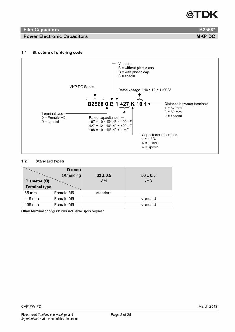
1.1 Structure of ordering code
1.2 Standard types
D (mm)
OC ending
Diameter (Ø)
Terminal type
32 ± 0.5
-**1
50 ± 0.5
-**3
85 mm Female M6 standard
116 mm Female M6 standard
136 mm Female M6 standard
Other terminal configurations available upon request.
Terminal type: 0 = Female M6 9 = special
B2568 0 B 1 427 K 10 1
MKP DC Series
Version: B = without plastic cap C = with plastic cap S = special
Rated voltage: 110 • 10 = 1100 V
Rated capacitance: 107 = 10 ꞏ 107 pF = 100 µF 427 = 42 ꞏ 107 pF = 420 µF 108 = 10 ꞏ 108 pF = 1 mF
Distance between terminals: 1 = 32 mm 3 = 50 mm 9 = special
Capacitance tolerance J = ± 5% K = ± 10% A = special
Film Capacitors B2568*
Power Electronic Capacitors MKP DC
CAP PW PD March 2019
Please read Cautions and warnings and Page 4 of 25 Important notes at the end of this document.
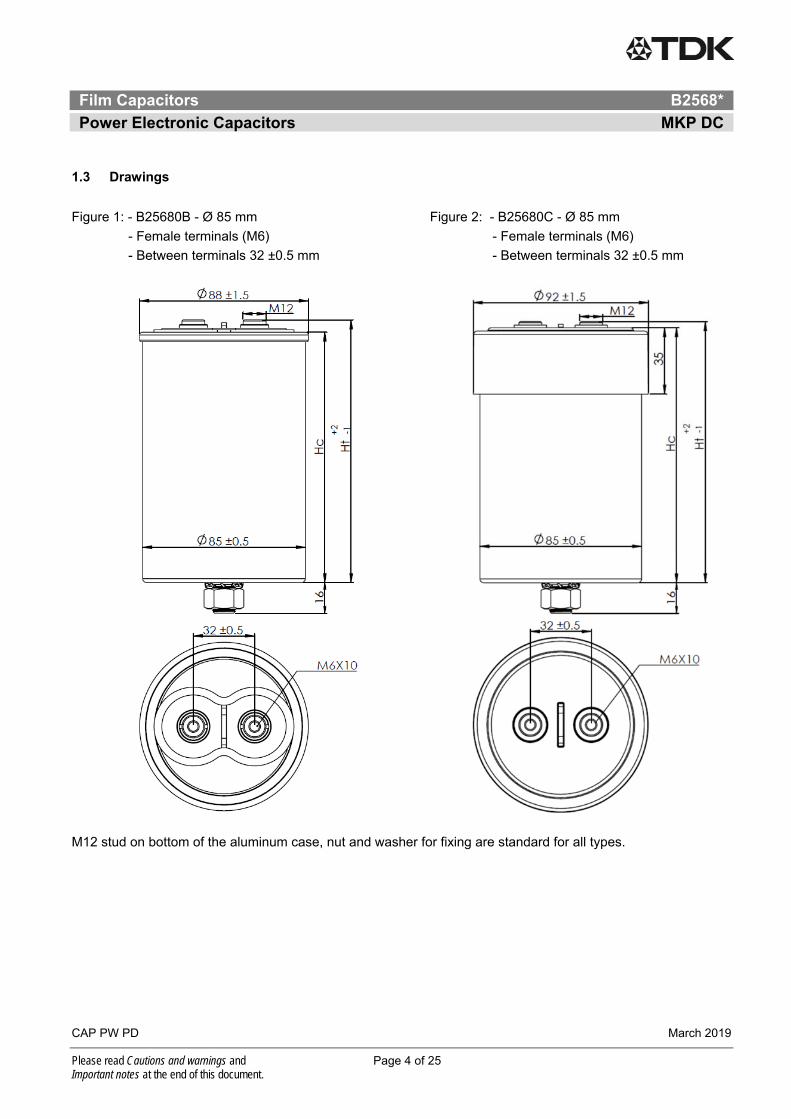
1.3 Drawings
Figure 1: - B25680B - Ø 85 mm Figure 2: - B25680C - Ø 85 mm
- Female terminals (M6) - Female terminals (M6)
- Between terminals 32 ±0.5 mm - Between terminals 32 ±0.5 mm
M12 stud on bottom of the aluminum case, nut and washer for fixing are standard for all types.
Film Capacitors B2568*
Power Electronic Capacitors MKP DC
CAP PW PD March 2019
Please read Cautions and warnings and Page 5 of 25 Important notes at the end of this document.
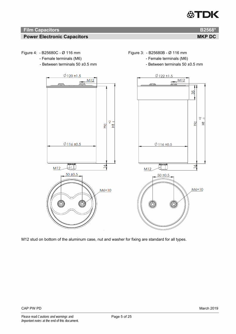
Figure 4: - B25680C - Ø 116 mm Figure 3: - B25680B - Ø 116 mm
- Female terminals (M6) - Female terminals (M6)
- Between terminals 50 ±0.5 mm - Between terminals 50 ±0.5 mm
M12 stud on bottom of the aluminum case, nut and washer for fixing are standard for all types.
Film Capacitors B2568*
Power Electronic Capacitors MKP DC
CAP PW PD March 2019
Please read Cautions and warnings and Page 6 of 25 Important notes at the end of this document.
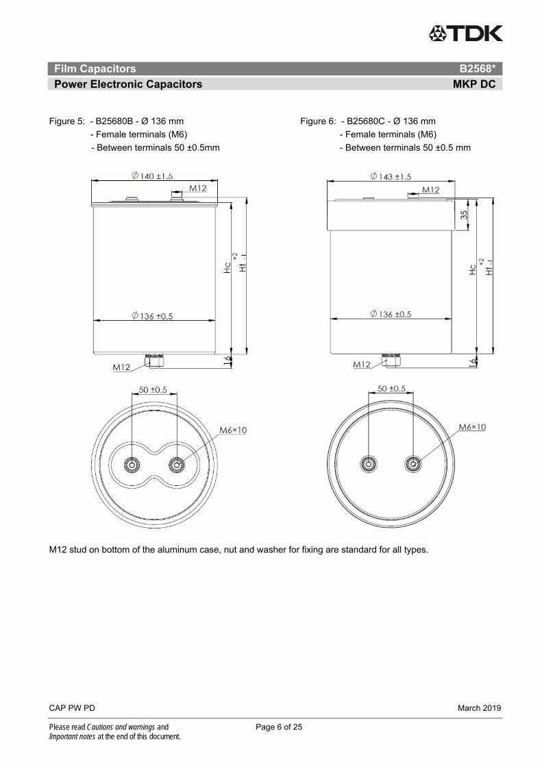
Figure 5: - B25680B - Ø 136 mm Figure 6: - B25680C - Ø 136 mm
- Female terminals (M6) - Female terminals (M6)
- Between terminals 50 ±0.5mm - Between terminals 50 ±0.5 mm
M12 stud on bottom of the aluminum case, nut and washer for fixing are standard for all types.
Film Capacitors B2568*
Power Electronic Capacitors MKP DC
CAP PW PD March 2019
Please read Cautions and warnings and Page 7 of 25 Important notes at the end of this document.
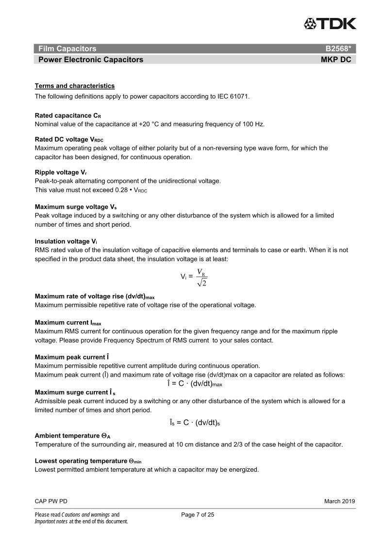
Terms and characteristics
The following definitions apply to power capacitors according to IEC 61071.
Rated capacitance CR Nominal value of the capacitance at +20 °C and measuring frequency of 100 Hz. Rated DC voltage VRDC Maximum operating peak voltage of either polarity but of a non-reversing type wave form, for which the
capacitor has been designed, for continuous operation. Ripple voltage Vr Peak-to-peak alternating component of the unidirectional voltage.
This value must not exceed 0.28 • VRDC
Maximum surge voltage Vs Peak voltage induced by a switching or any other disturbance of the system which is allowed for a limited
number of times and short period.
Insulation voltage Vi RMS rated value of the insulation voltage of capacitive elements and terminals to case or earth. When it is not
specified in the product data sheet, the insulation voltage is at least:
Vi = 2RV
Maximum rate of voltage rise (dv/dt)max
Maximum permissible repetitive rate of voltage rise of the operational voltage.
Maximum current Imax
Maximum RMS current for continuous operation for the given frequency range and for the maximum ripple
voltage. Please provide Frequency Spectrum of RMS current to your sales contact.
Maximum peak current Î Maximum permissible repetitive current amplitude during continuous operation.
Maximum peak current (Î) and maximum rate of voltage rise (dv/dt)max on a capacitor are related as follows:
Î = C ∙ (dv/dt)max Maximum surge current Î s
Admissible peak current induced by a switching or any other disturbance of the system which is allowed for a
limited number of times and short period.
Îs = C ∙ (dv/dt)s
Ambient temperature A
Temperature of the surrounding air, measured at 10 cm distance and 2/3 of the case height of the capacitor. Lowest operating temperature min
Lowest permitted ambient temperature at which a capacitor may be energized.
Film Capacitors B2568*
Power Electronic Capacitors MKP DC
CAP PW PD March 2019
Please read Cautions and warnings and Page 8 of 25 Important notes at the end of this document.
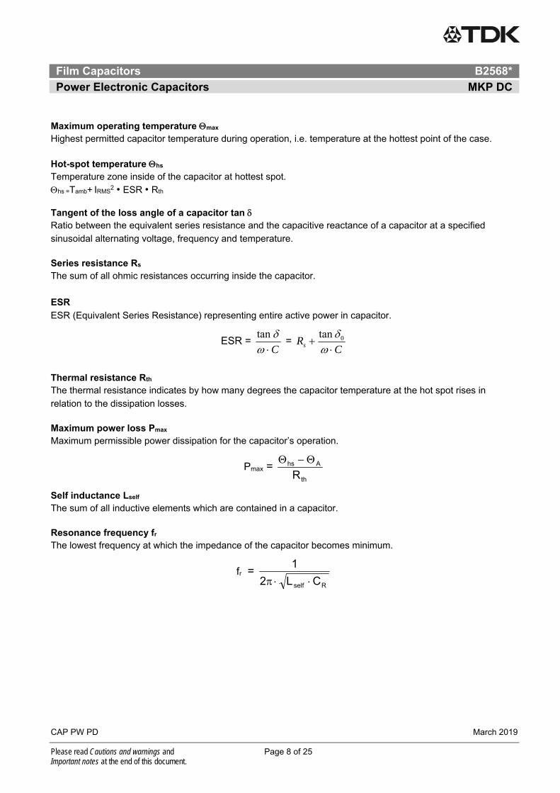
Maximum operating temperature max
Highest permitted capacitor temperature during operation, i.e. temperature at the hottest point of the case.
Hot-spot temperature hs
Temperature zone inside of the capacitor at hottest spot.
hs =Tamb+ IRMS2 • ESR • Rth
Tangent of the loss angle of a capacitor tan
Ratio between the equivalent series resistance and the capacitive reactance of a capacitor at a specified
sinusoidal alternating voltage, frequency and temperature.
Series resistance Rs
The sum of all ohmic resistances occurring inside the capacitor.
ESR
ESR (Equivalent Series Resistance) representing entire active power in capacitor.
ESR = Ctan
= C
Rs
0tan
Thermal resistance Rth
The thermal resistance indicates by how many degrees the capacitor temperature at the hot spot rises in
relation to the dissipation losses.
Maximum power loss Pmax
Maximum permissible power dissipation for the capacitor’s operation.
Pmax = th
Ahs
R
Self inductance Lself
The sum of all inductive elements which are contained in a capacitor.
Resonance frequency fr
The lowest frequency at which the impedance of the capacitor becomes minimum.
fr = Rself CL2
1
Film Capacitors B2568*
Power Electronic Capacitors MKP DC
CAP PW PD March 2019
Please read Cautions and warnings and Page 9 of 25 Important notes at the end of this document.
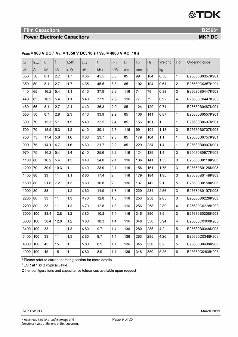
VRDC = 900 V DC / VTT = 1350 V DC, 10 s / VTC = 4000 V AC, 10 s
CR IMAX 1 Is Î ESR2 Lself f RTH D HC HT Weight Fig. Ordering code
µF A kA kA mΩ nH kHz K/W mm mm mm kg
350 50 8.1 2.7 1.7 ≤ 35 45.5 3.3 85 99 104 0.58 1 B25680B0357K901
350 50 8.1 2.7 1.7 ≤ 35 45.5 3.3 85 102 104 0.61 2 B25680C0357K901
440 65 16.2 5.4 1.1 ≤ 40 37.9 2.9 116 74 79 0.88 3 B25680B0447K903
440 65 16.2 5.4 1.1 ≤ 40 37.9 2.9 116 77 79 0.92 4 B25680C0447K903
480 55 8.1 2.7 2.1 ≤ 40 36.3 2.9 85 124 129 0.71 1 B25680B0487K901
550 50 8.7 2.9 2.3 ≤ 40 33.9 2.9 85 136 141 0.87 1 B25680B0557K901
600 70 15.3 5.1 1.5 ≤ 40 32.5 2.4 85 156 161 1 1 B25680B0607K901
700 70 15.9 5.3 1.2 ≤ 40 30.1 2.3 116 99 104 1.13 3 B25680B0707K903
750 75 17.4 5.8 1.6 ≤ 60 23.7 2.3 85 179 184 1.1 1 B25680B0757K901
900 75 14.1 4.7 1.6 ≤ 60 21.7 2.2 85 229 234 1.4 1 B25680B0907K901
970 75 16.2 5.4 1.4 ≤ 40 25.6 2.2 116 124 129 1.4 3 B25680B0977K903
1100 80 16.2 5.4 1.5 ≤ 40 24.0 2.1 116 136 141 1.55 3 B25680B0118K903
1200 70 30.9 10.3 1 ≤ 40 23.0 2.1 116 156 161 1.75 3 B25680B0128K903
1400 80 33 11 1.1 ≤ 60 17.4 2 116 179 184 1.95 3 B25680B0148K903
1500 80 21.6 7.2 1.3 ≤ 60 16.8 2 136 137 142 2.1 5 B25680B0158K903
1900 80 33 11 1.2 ≤ 60 14.9 1.8 116 229 234 2.56 3 B25680B0197K903
2200 80 33 11 1.3 ≤ 70 12.8 1.8 116 253 258 2.85 3 B25680B0228K903
2200 80 33 11 1.3 ≤ 70 12.8 1.8 116 256 258 2.89 4 B25680C0228K903
3000 100 38.4 12.8 1.2 ≤ 80 10.3 1.4 116 345 350 3.9 3 B25680B0308K903
3000 100 38.4 12.8 1.2 ≤ 80 10.3 1.4 116 348 350 3.94 4 B25680C0308K903
3400 100 33 11 1.3 ≤ 80 9.7 1.4 136 280 285 4.2 5 B25680B0348K903
3400 100 33 11 1.3 ≤ 80 9.7 1.4 136 283 285 4.26 6 B25680C0348K903
4000 100 45 15 1 ≤ 80 8.9 1.1 136 345 350 5.2 5 B25680B0408K903
4000 100 45 15 1 ≤ 80 8.9 1.1 136 348 350 5.26 6 B25680C0408K903
1 Please refer to current derating section for more details 2 ESR at 1 kHz (typical value)
Other configurations and capacitance tolerances available upon request
Film Capacitors B2568*
Power Electronic Capacitors MKP DC
CAP PW PD March 2019
Please read Cautions and warnings and Page 10 of 25 Important notes at the end of this document.
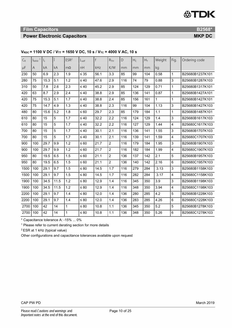
VRDC = 1100 V DC / VTT = 1650 V DC, 10 s / VTC = 4000 V AC, 10 s
CR IMAX 1 Is Î ESR2 Lself f RTH D HC HT Weight Fig. Ordering code
µF A kA kA mΩ nH kHz K/W mm mm mm kg
230 50 6.9 2.3 1.9 ≤ 35 56.1 3.3 85 99 104 0.58 1 B25680B1237K101
280 75 15.3 5.1 1.2 ≤ 40 47.6 2.9 116 74 79 0.88 3 B25680B1287K103
310 50 7.8 2.6 2.3 ≤ 40 45.2 2.9 85 124 129 0.71 1 B25680B1317K101
420 63 8.7 2.9 2.4 ≤ 40 38.8 2.9 85 136 141 0.87 1 B25680B1427A101
420 75 15.3 5.1 1.7 ≤ 40 38.8 2.4 85 156 161 1 1 B25680B1427K101
420 75 14.7 4.9 1.3 ≤ 40 38.8 2.3 116 99 104 1.13 3 B25680B1427K103
480 80 15.6 5.2 1.8 ≤ 60 29.7 2.3 85 179 184 1.1 1 B25680B1487K101
610 80 15 5 1.7 ≤ 40 32.2 2.2 116 124 129 1.4 3 B25680B1617K103
610 80 15 5 1.7 ≤ 40 32.2 2.2 116 127 129 1.44 4 B25680C1617K103
700 80 15 5 1.7 ≤ 40 30.1 2.1 116 136 141 1.55 3 B25680B1707K103
700 80 15 5 1.7 ≤ 40 30.1 2.1 116 139 141 1.59 4 B25680C1707K103
900 100 29.7 9.9 1.2 ≤ 60 21.7 2 116 179 184 1.95 3 B25680B1907K103
900 100 29.7 9.9 1.2 ≤ 60 21.7 2 116 182 184 1.99 4 B25680C1907K103
950 80 19.5 6.5 1.5 ≤ 60 21.1 2 136 137 142 2.1 5 B25680B1957K103
950 80 19.5 6.5 1.5 ≤ 60 21.1 2 136 140 142 2.16 6 B25680C1957K103
1500 100 29.1 9.7 1.5 ≤ 80 14.5 1.7 116 279 284 3.13 3 B25680B1158K103
1500 100 29.1 9.7 1.5 ≤ 80 14.5 1.7 116 282 284 3.17 4 B25680C1158K103
1900 100 34.5 11.5 1.2 ≤ 80 12.9 1.4 116 345 350 3.9 3 B25680B1198K103
1900 100 34.5 11.5 1.2 ≤ 80 12.9 1.4 116 348 350 3.94 4 B25680C1198K103
2200 100 29.1 9.7 1.4 ≤ 80 12.0 1.4 136 280 285 4.2 5 B25680B1228K103
2200 100 29.1 9.7 1.4 ≤ 80 12.0 1.4 136 283 285 4.26 6 B25680C1228K103
2700 100 42 14 1 ≤ 80 10.8 1.1 136 345 350 5.2 5 B25680B1278K103
2700 100 42 14 1 ≤ 80 10.8 1.1 136 348 350 5.26 6 B25680C1278K103
* Capacitance tolerance A: -15% ... 0% 1 Please refer to current derating section for more details 2 ESR at 1 kHz (typical value)
Other configurations and capacitance tolerances available upon request

Film Capacitors B2568*
Power Electronic Capacitors MKP DC
CAP PW PD March 2019
Please read Cautions and warnings and Page 11 of 25 Important notes at the end of this document.
VRDC = 1200 V DC / VTT = 1800 V DC, 10 s / VTC = 4000 V AC, 10 s
CR IMAX 1 Is Î ESR2 Lself f RTH D HC HT Weight Fig. Ordering code
µF A kA kA mΩ nH kHz K/W mm mm mm kg
180 50 6.9 2.3 2.1 ≤ 35 63.4 3.3 85 99 104 0.58 1 B25680B1187K201
250 50 7.2 2.4 2.4 ≤ 40 50.3 2.9 85 124 129 0.71 1 B25680B1257K201
280 50 7.2 2.4 2.5 ≤ 40 47.6 2.9 85 136 141 0.87 1 B25680B1287K201
300 65 14.1 4.7 1.8 ≤ 40 45.9 2.4 85 156 161 1 1 B25680B1307K201
350 65 13.5 4.5 1.9 ≤ 60 34.7 2.3 85 179 184 1.1 1 B25680B1357K201
350 65 13.5 4.5 1.9 ≤ 60 34.7 2.3 85 182 184 1.13 2 B25680C1357K201
360 70 14.7 4.9 1.6 ≤ 40 41.9 2.3 116 99 104 1.13 3 B25680B1367K203
360 70 14.7 4.9 1.6 ≤ 40 41.9 2.3 116 102 104 1.17 4 B25680C1367K203
500 75 15 5 1.7 ≤ 40 35.6 2.2 116 124 129 1.4 3 B25680B1507K203
500 75 15 5 1.7 ≤ 40 35.6 2.2 116 127 129 1.44 4 B25680C1507K203
520 70 13.8 4.6 1.6 ≤ 60 28.5 2.2 85 229 234 1.4 1 B25680B1527K201
520 70 13.8 4.6 1.6 ≤ 60 28.5 2.2 85 232 234 1.43 2 B25680C1527K201
570 75 15 5 1.7 ≤ 40 33.3 2.1 116 136 141 1.55 3 B25680B1577K203
570 75 15 5 1.7 ≤ 40 33.3 2.1 116 139 141 1.59 4 B25680C1577K203
620 80 29.1 9.7 1.3 ≤ 60 26.1 2.1 116 156 161 1.75 3 B25680B1627K203
620 80 29.1 9.7 1.3 ≤ 60 26.1 2.1 116 159 161 1.79 4 B25680C1627K203
730 100 29.4 9.8 1.3 ≤ 60 24.0 2 116 179 184 1.95 3 B25680B1737K203
730 100 29.4 9.8 1.3 ≤ 60 24.0 2 116 182 184 1.99 4 B25680C1737K203
800 75 19.5 6.5 1.5 ≤ 60 23.0 2 136 137 142 2.1 5 B25680B1807K203
800 75 19.5 6.5 1.5 ≤ 60 23.0 2 136 140 142 2.16 6 B25680C1807K203
1500 100 34.5 11.5 1.3 ≤ 80 14.5 1.4 116 345 350 3.9 3 B25680B1158K203
1500 100 34.5 11.5 1.3 ≤ 80 14.5 1.4 116 348 350 3.94 4 B25680C1158K203
2200 100 42 14 1 ≤ 80 12.0 1.1 136 345 350 5.2 5 B25680B1228K203
2200 100 42 14 1 ≤ 80 12.0 1.1 136 348 350 5.26 6 B25680C1228K203
1 Please refer to current derating section for more details 2 ESR at 1 kHz (typical value)
Other configurations and capacitance tolerances available upon request
Film Capacitors B2568*
Power Electronic Capacitors MKP DC
CAP PW PD March 2019
Please read Cautions and warnings and Page 12 of 25 Important notes at the end of this document.
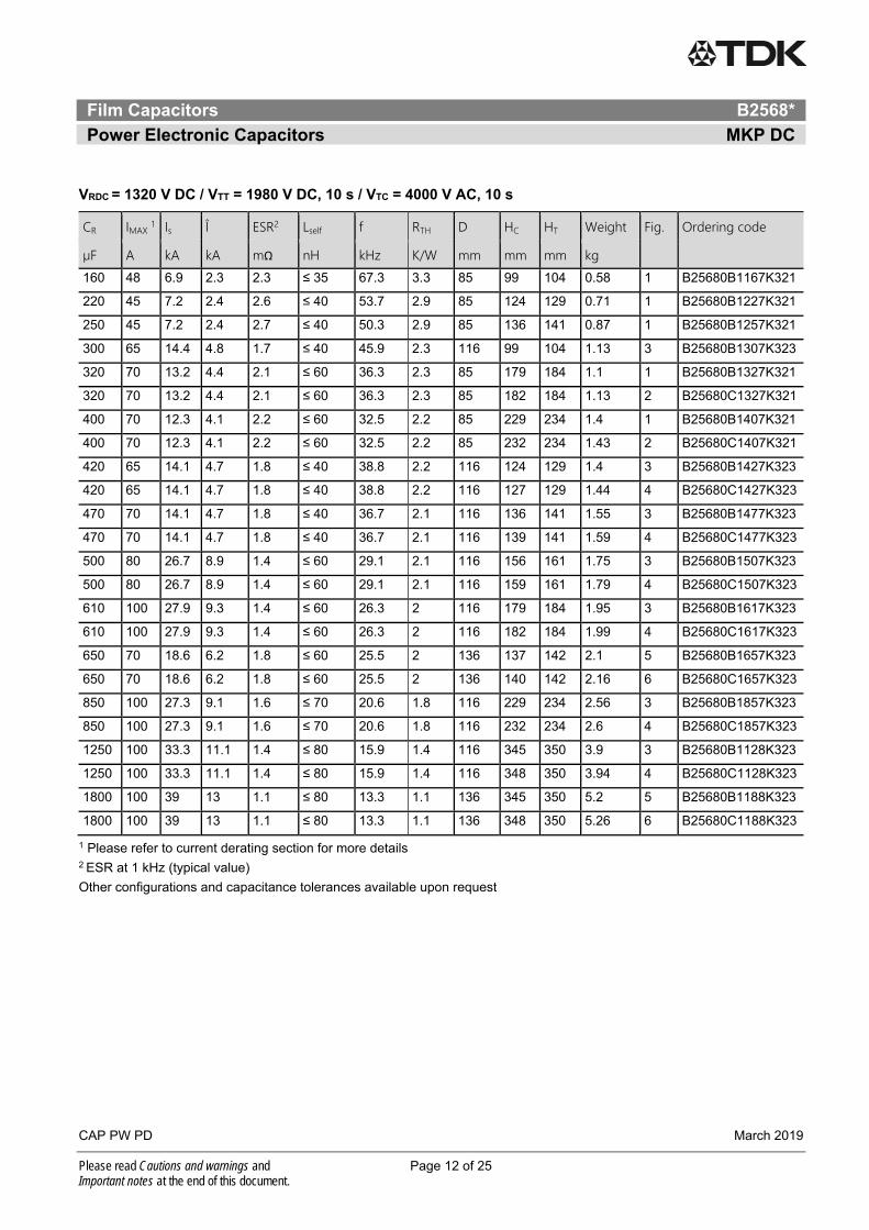
VRDC = 1320 V DC / VTT = 1980 V DC, 10 s / VTC = 4000 V AC, 10 s
CR IMAX 1 Is Î ESR2 Lself f RTH D HC HT Weight Fig. Ordering code
µF A kA kA mΩ nH kHz K/W mm mm mm kg
160 48 6.9 2.3 2.3 ≤ 35 67.3 3.3 85 99 104 0.58 1 B25680B1167K321
220 45 7.2 2.4 2.6 ≤ 40 53.7 2.9 85 124 129 0.71 1 B25680B1227K321
250 45 7.2 2.4 2.7 ≤ 40 50.3 2.9 85 136 141 0.87 1 B25680B1257K321
300 65 14.4 4.8 1.7 ≤ 40 45.9 2.3 116 99 104 1.13 3 B25680B1307K323
320 70 13.2 4.4 2.1 ≤ 60 36.3 2.3 85 179 184 1.1 1 B25680B1327K321
320 70 13.2 4.4 2.1 ≤ 60 36.3 2.3 85 182 184 1.13 2 B25680C1327K321
400 70 12.3 4.1 2.2 ≤ 60 32.5 2.2 85 229 234 1.4 1 B25680B1407K321
400 70 12.3 4.1 2.2 ≤ 60 32.5 2.2 85 232 234 1.43 2 B25680C1407K321
420 65 14.1 4.7 1.8 ≤ 40 38.8 2.2 116 124 129 1.4 3 B25680B1427K323
420 65 14.1 4.7 1.8 ≤ 40 38.8 2.2 116 127 129 1.44 4 B25680C1427K323
470 70 14.1 4.7 1.8 ≤ 40 36.7 2.1 116 136 141 1.55 3 B25680B1477K323
470 70 14.1 4.7 1.8 ≤ 40 36.7 2.1 116 139 141 1.59 4 B25680C1477K323
500 80 26.7 8.9 1.4 ≤ 60 29.1 2.1 116 156 161 1.75 3 B25680B1507K323
500 80 26.7 8.9 1.4 ≤ 60 29.1 2.1 116 159 161 1.79 4 B25680C1507K323
610 100 27.9 9.3 1.4 ≤ 60 26.3 2 116 179 184 1.95 3 B25680B1617K323
610 100 27.9 9.3 1.4 ≤ 60 26.3 2 116 182 184 1.99 4 B25680C1617K323
650 70 18.6 6.2 1.8 ≤ 60 25.5 2 136 137 142 2.1 5 B25680B1657K323
650 70 18.6 6.2 1.8 ≤ 60 25.5 2 136 140 142 2.16 6 B25680C1657K323
850 100 27.3 9.1 1.6 ≤ 70 20.6 1.8 116 229 234 2.56 3 B25680B1857K323
850 100 27.3 9.1 1.6 ≤ 70 20.6 1.8 116 232 234 2.6 4 B25680C1857K323
1250 100 33.3 11.1 1.4 ≤ 80 15.9 1.4 116 345 350 3.9 3 B25680B1128K323
1250 100 33.3 11.1 1.4 ≤ 80 15.9 1.4 116 348 350 3.94 4 B25680C1128K323
1800 100 39 13 1.1 ≤ 80 13.3 1.1 136 345 350 5.2 5 B25680B1188K323
1800 100 39 13 1.1 ≤ 80 13.3 1.1 136 348 350 5.26 6 B25680C1188K323
1 Please refer to current derating section for more details 2 ESR at 1 kHz (typical value)
Other configurations and capacitance tolerances available upon request
Film Capacitors B2568*
Power Electronic Capacitors MKP DC
CAP PW PD March 2019
Please read Cautions and warnings and Page 13 of 25 Important notes at the end of this document.
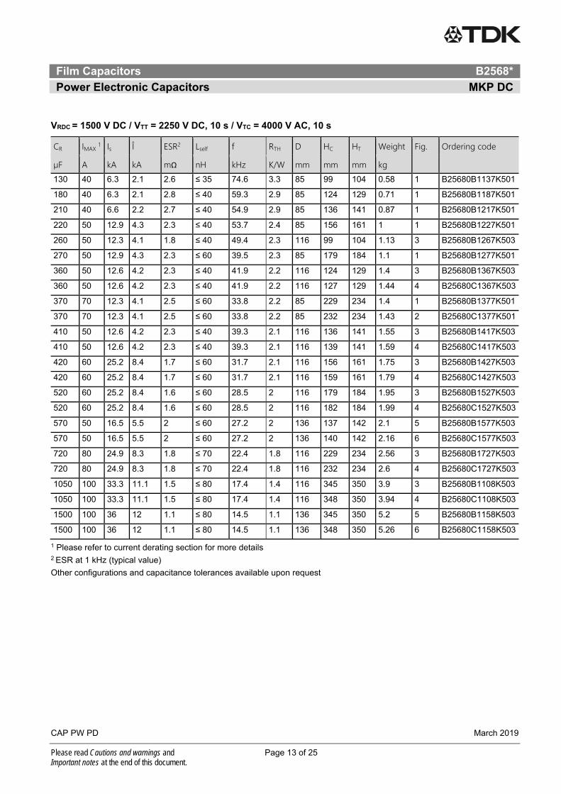
VRDC = 1500 V DC / VTT = 2250 V DC, 10 s / VTC = 4000 V AC, 10 s
CR IMAX 1 Is Î ESR2 Lself f RTH D HC HT Weight Fig. Ordering code
µF A kA kA mΩ nH kHz K/W mm mm mm kg
130 40 6.3 2.1 2.6 ≤ 35 74.6 3.3 85 99 104 0.58 1 B25680B1137K501
180 40 6.3 2.1 2.8 ≤ 40 59.3 2.9 85 124 129 0.71 1 B25680B1187K501
210 40 6.6 2.2 2.7 ≤ 40 54.9 2.9 85 136 141 0.87 1 B25680B1217K501
220 50 12.9 4.3 2.3 ≤ 40 53.7 2.4 85 156 161 1 1 B25680B1227K501
260 50 12.3 4.1 1.8 ≤ 40 49.4 2.3 116 99 104 1.13 3 B25680B1267K503
270 50 12.9 4.3 2.3 ≤ 60 39.5 2.3 85 179 184 1.1 1 B25680B1277K501
360 50 12.6 4.2 2.3 ≤ 40 41.9 2.2 116 124 129 1.4 3 B25680B1367K503
360 50 12.6 4.2 2.3 ≤ 40 41.9 2.2 116 127 129 1.44 4 B25680C1367K503
370 70 12.3 4.1 2.5 ≤ 60 33.8 2.2 85 229 234 1.4 1 B25680B1377K501
370 70 12.3 4.1 2.5 ≤ 60 33.8 2.2 85 232 234 1.43 2 B25680C1377K501
410 50 12.6 4.2 2.3 ≤ 40 39.3 2.1 116 136 141 1.55 3 B25680B1417K503
410 50 12.6 4.2 2.3 ≤ 40 39.3 2.1 116 139 141 1.59 4 B25680C1417K503
420 60 25.2 8.4 1.7 ≤ 60 31.7 2.1 116 156 161 1.75 3 B25680B1427K503
420 60 25.2 8.4 1.7 ≤ 60 31.7 2.1 116 159 161 1.79 4 B25680C1427K503
520 60 25.2 8.4 1.6 ≤ 60 28.5 2 116 179 184 1.95 3 B25680B1527K503
520 60 25.2 8.4 1.6 ≤ 60 28.5 2 116 182 184 1.99 4 B25680C1527K503
570 50 16.5 5.5 2 ≤ 60 27.2 2 136 137 142 2.1 5 B25680B1577K503
570 50 16.5 5.5 2 ≤ 60 27.2 2 136 140 142 2.16 6 B25680C1577K503
720 80 24.9 8.3 1.8 ≤ 70 22.4 1.8 116 229 234 2.56 3 B25680B1727K503
720 80 24.9 8.3 1.8 ≤ 70 22.4 1.8 116 232 234 2.6 4 B25680C1727K503
1050 100 33.3 11.1 1.5 ≤ 80 17.4 1.4 116 345 350 3.9 3 B25680B1108K503
1050 100 33.3 11.1 1.5 ≤ 80 17.4 1.4 116 348 350 3.94 4 B25680C1108K503
1500 100 36 12 1.1 ≤ 80 14.5 1.1 136 345 350 5.2 5 B25680B1158K503
1500 100 36 12 1.1 ≤ 80 14.5 1.1 136 348 350 5.26 6 B25680C1158K503
1 Please refer to current derating section for more details 2 ESR at 1 kHz (typical value)
Other configurations and capacitance tolerances available upon request

Film Capacitors B2568*
Power Electronic Capacitors MKP DC
CAP PW PD March 2019
Please read Cautions and warnings and Page 14 of 25 Important notes at the end of this document.
VRDC = 2000 V DC / VTT = 3000 V DC, 10 s / VTC = 4000 V AC, 10 s
CR IMAX 1 Is Î ESR2 Lself f RTH D HC HT Weight Fig. Ordering code
µF A kA kA mΩ nH kHz K/W mm mm mm kg
70 40 4.8 1.6 3.5 ≤ 35 101.7 3.3 85 99 104 0.58 1 B25680B2706K001
70 40 4.8 1.6 3.5 ≤ 35 101.7 3.3 85 102 104 0.61 2 B25680C2706K001
95 40 4.8 1.6 3.6 ≤ 40 81.6 2.9 85 124 129 0.71 1 B25680B2956K001
95 40 4.8 1.6 3.6 ≤ 40 81.6 2.9 85 127 129 0.74 2 B25680C2956K001
110 40 4.5 1.5 3.6 ≤ 40 75.9 2.9 85 136 141 0.87 1 B25680B2117K001
110 40 4.5 1.5 3.6 ≤ 40 75.9 2.9 85 139 141 0.9 2 B25680C2117K001
130 50 10.2 3.4 2.7 ≤ 60 57.0 2.3 85 179 184 1.1 1 B25680B2137K001
130 50 10.2 3.4 2.7 ≤ 60 57.0 2.3 85 182 184 1.13 2 B25680C2137K001
180 60 9.6 3.2 2.8 ≤ 40 59.3 2.2 116 124 129 1.4 3 B25680B2187K003
180 60 9.6 3.2 2.8 ≤ 40 59.3 2.2 116 127 129 1.44 4 B25680C2187K003
190 70 9.3 3.1 2.8 ≤ 60 47.1 2.2 85 229 234 1.4 1 B25680B2197K001
190 70 9.3 3.1 2.8 ≤ 60 47.1 2.2 85 232 234 1.43 2 B25680C2197K001
205 60 9.6 3.2 2.9 ≤ 40 55.6 2.1 116 136 141 1.55 3 B25680B2207K003
205 60 9.6 3.2 2.9 ≤ 40 55.6 2.1 116 139 141 1.59 4 B25680C2207K003
210 80 17.7 5.9 1.8 ≤ 60 44.8 2.1 116 156 161 1.75 3 B25680B2217K003
210 80 17.7 5.9 1.8 ≤ 60 44.8 2.1 116 159 161 1.79 4 B25680C2217K003
260 80 18.9 6.3 1.9 ≤ 60 40.3 2 116 179 184 1.95 3 B25680B2267K003
260 80 18.9 6.3 1.9 ≤ 60 40.3 2 116 182 184 1.99 4 B25680C2267K003
290 60 12.6 4.2 2.7 ≤ 60 38.2 2 136 137 142 2.1 5 B25680B2297K003
290 60 12.6 4.2 2.7 ≤ 60 38.2 2 136 140 142 2.16 6 B25680C2297K003
470 100 19.2 6.4 3 ≤ 80 26.0 1.7 116 279 284 3.13 3 B25680B2477K003
470 100 19.2 6.4 3 ≤ 80 26.0 1.7 116 282 284 3.17 4 B25680C2477K003
800 100 27 9 1.1 ≤ 80 19.9 1.1 136 345 350 5.2 5 B25680B2807K003
800 100 27 9 1.1 ≤ 80 19.9 1.1 136 348 350 5.26 6 B25680C2807K003
1 Please refer to current derating section for more details 2 ESR at 1 kHz (typical value)
Other configurations and capacitance tolerances available upon request
Film Capacitors B2568*
Power Electronic Capacitors MKP DC
CAP PW PD March 2019
Please read Cautions and warnings and Page 15 of 25 Important notes at the end of this document.
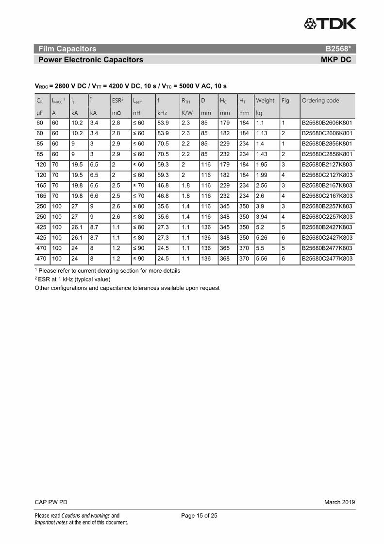
VRDC = 2800 V DC / VTT = 4200 V DC, 10 s / VTC = 5000 V AC, 10 s
CR IMAX 1 Is Î ESR2 Lself f RTH D HC HT Weight Fig. Ordering code
µF A kA kA mΩ nH kHz K/W mm mm mm kg
60 60 10.2 3.4 2.8 ≤ 60 83.9 2.3 85 179 184 1.1 1 B25680B2606K801
60 60 10.2 3.4 2.8 ≤ 60 83.9 2.3 85 182 184 1.13 2 B25680C2606K801
85 60 9 3 2.9 ≤ 60 70.5 2.2 85 229 234 1.4 1 B25680B2856K801
85 60 9 3 2.9 ≤ 60 70.5 2.2 85 232 234 1.43 2 B25680C2856K801
120 70 19.5 6.5 2 ≤ 60 59.3 2 116 179 184 1.95 3 B25680B2127K803
120 70 19.5 6.5 2 ≤ 60 59.3 2 116 182 184 1.99 4 B25680C2127K803
165 70 19.8 6.6 2.5 ≤ 70 46.8 1.8 116 229 234 2.56 3 B25680B2167K803
165 70 19.8 6.6 2.5 ≤ 70 46.8 1.8 116 232 234 2.6 4 B25680C2167K803
250 100 27 9 2.6 ≤ 80 35.6 1.4 116 345 350 3.9 3 B25680B2257K803
250 100 27 9 2.6 ≤ 80 35.6 1.4 116 348 350 3.94 4 B25680C2257K803
425 100 26.1 8.7 1.1 ≤ 80 27.3 1.1 136 345 350 5.2 5 B25680B2427K803
425 100 26.1 8.7 1.1 ≤ 80 27.3 1.1 136 348 350 5.26 6 B25680C2427K803
470 100 24 8 1.2 ≤ 90 24.5 1.1 136 365 370 5.5 5 B25680B2477K803
470 100 24 8 1.2 ≤ 90 24.5 1.1 136 368 370 5.56 6 B25680C2477K803
1 Please refer to current derating section for more details 2 ESR at 1 kHz (typical value)
Other configurations and capacitance tolerances available upon request
Film Capacitors B2568*
Power Electronic Capacitors MKP DC
CAP PW PD March 2019
Please read Cautions and warnings and Page 16 of 25 Important notes at the end of this document.
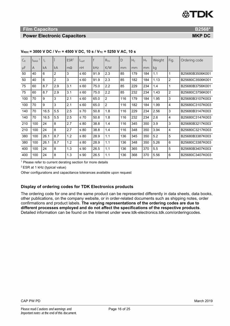
VRDC = 3000 V DC / VTT = 4500 V DC, 10 s / VTC = 5250 V AC, 10 s
CR IMAX 1 Is Î ESR2 Lself f RTH D HC HT Weight Fig. Ordering code
µF A kA kA mΩ nH kHz K/W mm mm mm kg
50 40 6 2 3 ≤ 60 91.9 2.3 85 179 184 1.1 1 B25680B3506K001
50 40 6 2 3 ≤ 60 91.9 2.3 85 182 184 1.13 2 B25680C3506K001
75 60 8.7 2.9 3.1 ≤ 60 75.0 2.2 85 229 234 1.4 1 B25680B3756K001
75 60 8.7 2.9 3.1 ≤ 60 75.0 2.2 85 232 234 1.43 2 B25680C3756K001
100 70 9 3 2.1 ≤ 60 65.0 2 116 179 184 1.95 3 B25680B3107K003
100 70 9 3 2.1 ≤ 60 65.0 2 116 182 184 1.99 4 B25680C3107K003
140 70 16.5 5.5 2.5 ≤ 70 50.8 1.8 116 229 234 2.56 3 B25680B3147K003
140 70 16.5 5.5 2.5 ≤ 70 50.8 1.8 116 232 234 2.6 4 B25680C3147K003
210 100 24 8 2.7 ≤ 80 38.8 1.4 116 345 350 3.9 3 B25680B3217K003
210 100 24 8 2.7 ≤ 80 38.8 1.4 116 348 350 3.94 4 B25680C3217K003
380 100 26.1 8.7 1.2 ≤ 80 28.9 1.1 136 345 350 5.2 5 B25680B3387K003
380 100 26.1 8.7 1.2 ≤ 80 28.9 1.1 136 348 350 5.26 6 B25680C3387K003
400 100 24 8 1.3 ≤ 90 26.5 1.1 136 365 370 5.5 5 B25680B3407K003
400 100 24 8 1.3 ≤ 90 26.5 1.1 136 368 370 5.56 6 B25680C3407K003
1 Please refer to current derating section for more details 2 ESR at 1 kHz (typical value)
Other configurations and capacitance tolerances available upon request
Display of ordering codes for TDK Electronics products
The ordering code for one and the same product can be represented differently in data sheets, data books, other publications, on the company website, or in order-related documents such as shipping notes, order confirmations and product labels. The varying representations of the ordering codes are due to different processes employed and do not affect the specifications of the respective products. Detailed information can be found on the Internet under www.tdk-electronics.tdk.com/orderingcodes.
Film Capacitors B2568*
Power Electronic Capacitors MKP DC
CAP PW PD March 2019
Please read Cautions and warnings and Page 17 of 25 Important notes at the end of this document.
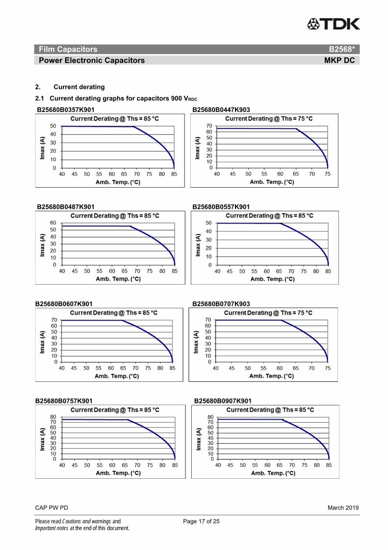
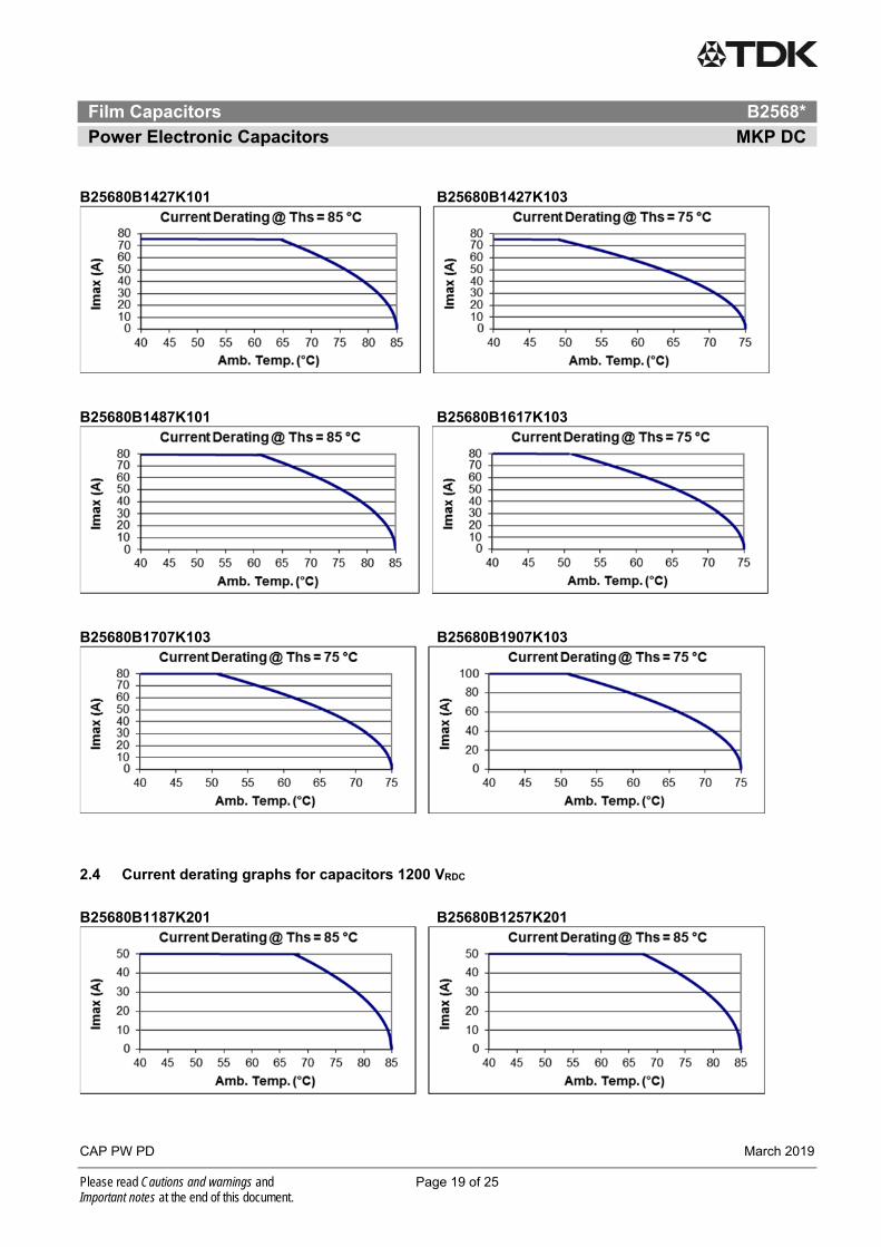
2. Current derating
2.1 Current derating graphs for capacitors 900 VRDC
B25680B0357K901 B25680B0447K903
B25680B0487K901 B25680B0557K901
B25680B0607K901 B25680B0707K903
B25680B0757K901 B25680B0907K901
Film Capacitors B2568*
Power Electronic Capacitors MKP DC
CAP PW PD March 2019
Please read Cautions and warnings and Page 18 of 25 Important notes at the end of this document.
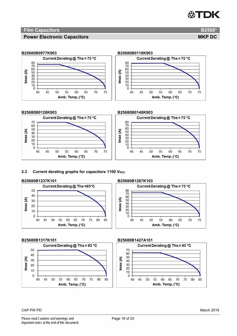
B25680B0977K903 B25680B0118K903
B25680B0128K903 B25680B0148K903
2.3 Current derating graphs for capacitors 1100 VRDC B25680B1237K101 B25680B1287K103
B25680B1317K101 B25680B1427A101
Film Capacitors B2568*
Power Electronic Capacitors MKP DC
CAP PW PD March 2019
Please read Cautions and warnings and Page 19 of 25 Important notes at the end of this document.
B25680B1427K101 B25680B1427K103
B25680B1487K101 B25680B1617K103
B25680B1707K103 B25680B1907K103
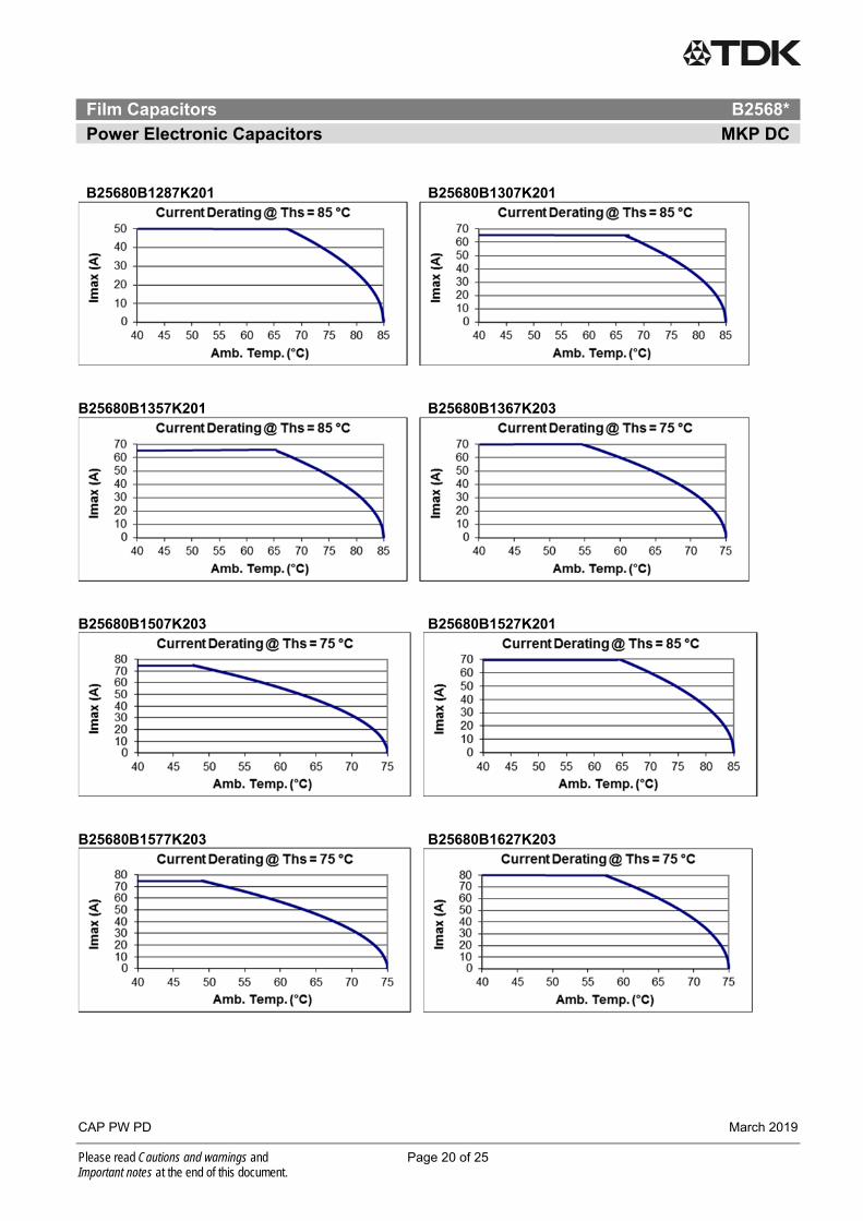
2.4 Current derating graphs for capacitors 1200 VRDC
B25680B1187K201 B25680B1257K201
Film Capacitors B2568*
Power Electronic Capacitors MKP DC
CAP PW PD March 2019
Please read Cautions and warnings and Page 20 of 25 Important notes at the end of this document.
B25680B1287K201 B25680B1307K201
B25680B1357K201 B25680B1367K203
B25680B1507K203 B25680B1527K201
B25680B1577K203 B25680B1627K203
Film Capacitors B2568*
Power Electronic Capacitors MKP DC
CAP PW PD March 2019
Please read Cautions and warnings and Page 21 of 25 Important notes at the end of this document.
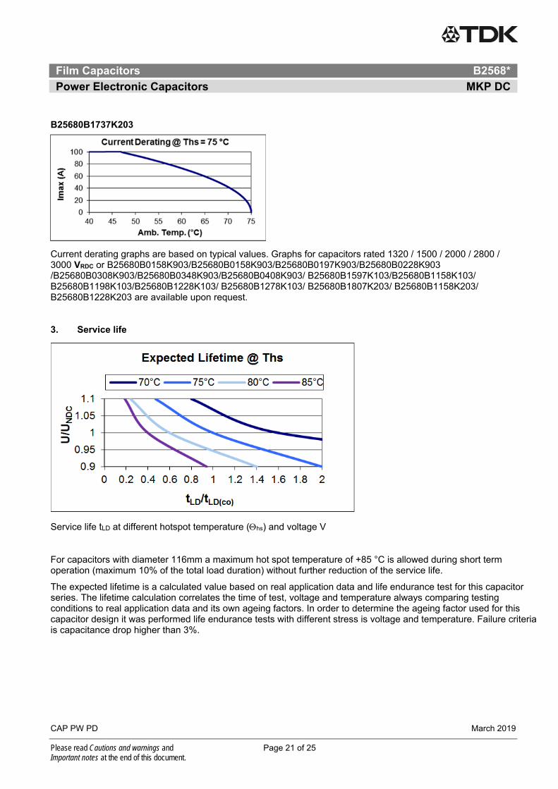
B25680B1737K203
Current derating graphs are based on typical values. Graphs for capacitors rated 1320 / 1500 / 2000 / 2800 / 3000 VRDC or B25680B0158K903/B25680B0158K903/B25680B0197K903/B25680B0228K903 /B25680B0308K903/B25680B0348K903/B25680B0408K903/ B25680B1597K103/B25680B1158K103/ B25680B1198K103/B25680B1228K103/ B25680B1278K103/ B25680B1807K203/ B25680B1158K203/ B25680B1228K203 are available upon request. 3. Service life
Service life tLD at different hotspot temperature (hs) and voltage V
For capacitors with diameter 116mm a maximum hot spot temperature of +85 °C is allowed during short term operation (maximum 10% of the total load duration) without further reduction of the service life.
The expected lifetime is a calculated value based on real application data and life endurance test for this capacitor series. The lifetime calculation correlates the time of test, voltage and temperature always comparing testing conditions to real application data and its own ageing factors. In order to determine the ageing factor used for this capacitor design it was performed life endurance tests with different stress is voltage and temperature. Failure criteria is capacitance drop higher than 3%.
Film Capacitors B2568*
Power Electronic Capacitors MKP DC
CAP PW PD March 2019
Please read Cautions and warnings and Page 22 of 25 Important notes at the end of this document.
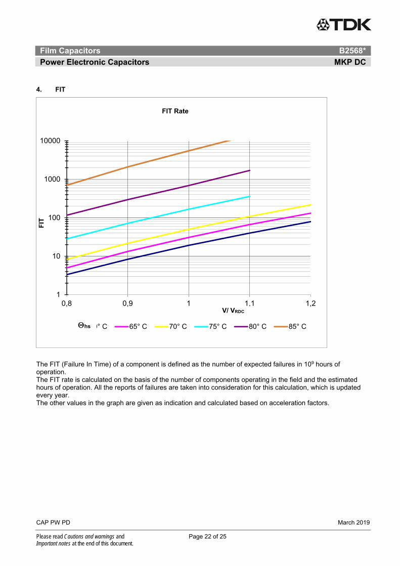
4. FIT
The FIT (Failure In Time) of a component is defined as the number of expected failures in 109 hours of operation. The FIT rate is calculated on the basis of the number of components operating in the field and the estimated hours of operation. All the reports of failures are taken into consideration for this calculation, which is updated every year. The other values in the graph are given as indication and calculated based on acceleration factors.
1
10
100
1000
10000
0,8 0,9 1 1,1 1,2
FIT
FIT Rate
60° C 65° C 70° C 75° C 80° C 85° C
V/ VRDC
hs
Film Capacitors B2568*
Power Electronic Capacitors MKP DC
CAP PW PD March 2019
Please read Cautions and warnings and Page 23 of 25 Important notes at the end of this document.
Cautions and warnings
In case of dents of more than 1 mm depth or any other mechanical damage, capacitors must not be used at all.
Check tightness of the connections/terminals periodically.
The energy stored in capacitors may be lethal. To prevent any chance of shock, discharge and short-circuit the capacitor before handling.
Failure to follow cautions may result, worst case, in premature failures, bursting and fire.
TDK is not responsible for any kind of possible damages to persons or things due to improper installation and application of capacitors for power electronics.
Safety
Electrical or mechanical misapplication of capacitors may be hazardous. Personal injury or property damage may result from bursting of the capacitor or from expulsion of oil or melted material due to mechanical disruption of the capacitor.
Ensure good, effective grounding for capacitor enclosures.
Observe appropriate safety precautions during operation (self-recharging phenomena and the high energy contained in capacitors).
Handle capacitors carefully, because they may still be charged even after disconnection.
The terminals of capacitors, connected bus bars and cables as well as other devices may also be energized.
Follow good engineering practice.
Thermal load
After installation of the capacitor it is necessary to verify that maximum hot-spot temperature is not exceeded at extreme service conditions.
Mechanical protection
The capacitor has to be installed in a way that mechanical damages and dents in the aluminum can are avoided.
Storage and operating conditions
Do not use or store capacitors in corrosive atmosphere, especially where chloride gas, sulfide gas, acid, alkali, salt or the like are present. In dusty environments regular maintenance and cleaning especially of the terminals is required to avoid conductive path between phases and/or phases and ground.
The maximum storage temperature is +85 °C.
Service life expectancy
Electrical components do not have an unlimited service life expectancy; this applies to self-healing capacitors, too. The maximum service life expectancy may vary depending on the application the capacitor is used in.
Important notes
Page 24 of 25
The following applies to all products named in this publication:
1. Some parts of this publication contain statements about the suitability of our products for certain areas of application. These statements are based on our knowledge of typical requirements that are often placed on our products in the areas of application concerned. We nevertheless expressly point out that such statements cannot be regarded as binding statements about the suitability of our products for a particular customer application. As a rule we are either unfamiliar with individual customer applications or less familiar with them than the customers themselves. For these reasons, it is always ultimately incumbent on the customer to check and decide whether a product with the properties described in the product specification is suitable for use in a particular customer application.
2. We also point out that in individual cases, a malfunction of electronic components or failure before the end of their usual service life cannot be completely ruled out in the current state of the art, even if they are operated as specified. In customer applications requiring a very high level of operational safety and especially in customer applications in which the malfunction or failure of an electronic component could endanger human life or health (e.g. in accident prevention or life-saving systems), it must therefore be ensured by means of suitable design of the customer application or other action taken by the customer (e.g. installation of protective circuitry or redundancy) that no injury or damage is sustained by third parties in the event of malfunction or failure of an electronic component.
3. The warnings, cautions and product-specific notes must be observed.
4. In order to satisfy certain technical requirements, some of the products described in this publication may contain substances subject to restrictions in certain jurisdictions (e.g. because they are classed as hazardous). Useful information on this will be found in our Material Data Sheets on the Internet (www.tdk-electronics.tdk.com/material). Should you have any more detailed questions, please contact our sales offices.
5. We constantly strive to improve our products. Consequently, the products described in this publication may change from time to time. The same is true of the corresponding product specifications. Please check therefore to what extent product descriptions and specifications contained in this publication are still applicable before or when you place an order.
We also reserve the right to discontinue production and delivery of products. Consequently, we cannot guarantee that all products named in this publication will always be available. The aforementioned does not apply in the case of individual agreements deviating from the foregoing for customer-specific products.
6. Unless otherwise agreed in individual contracts, all orders are subject to our General Terms and Conditions of Supply.
7. Our manufacturing sites serving the automotive business apply the IATF 16949 standard. The IATF certifications confirm our compliance with requirements regarding the quality management system in the automotive industry. Referring to customer requirements and customer specific requirements (“CSR”) TDK always has and will continue to have the policy of respecting individual agreements. Even if IATF 16949 may appear to support the acceptance of unilateral requirements, we hereby like to emphasize that only requirements mutually agreed upon can and will be implemented in our Quality Management System. For clarification purposes we like to point out that obligations from IATF 16949 shall only become legally binding if individually agreed upon.
Important notes
Page 25 of 25
8. The trade names EPCOS, CeraCharge, CeraDiode, CeraLink, CeraPad, CeraPlas, CSMP, CTVS, DeltaCap, DigiSiMic, ExoCore, FilterCap, FormFit, LeaXield, MiniBlue, MiniCell, MKD, MKK, MotorCap, PCC, PhaseCap, PhaseCube, PhaseMod, PhiCap, PowerHap, PQSine, PQvar, SIFERRIT, SIFI, SIKOREL, SilverCap, SIMDAD, SiMic, SIMID, SineFormer, SIOV, ThermoFuse, WindCap are trademarks registered or pending in Europe and in other countries. Further information will be found on the Internet at www.tdk-electronics.tdk.com/trademarks.
Release 2018-10