downloads.semi.orgdownloads.semi.org/.../$FILE/5997A.docx · Web viewBy selecting a representative...
28
Background Statement for SEMI Draft Document 5997A REVISION TO SEMI C3-0413, SPECIFICATIONS FOR GASES Notice: This background statement is not part of the balloted item. It is provided solely to assist the recipient in reaching an informed decision based on the rationale of the activity that preceded the creation of this Document. Notice: Recipients of this Document are invited to submit, with their comments, notification of any relevant patented technology or copyrighted items of which they are aware and to provide supporting documentation. In this context, “patented technology” is defined as technology for which a patent has issued or has been applied for. In the latter case, only publicly available information on the contents of the patent application is to be provided. Background Document 5997, line item ballot, was approved for ballot to correct the nonconforming title in Cycle 4-16. Unrelated comments were received from the LI ballot, which required failing of the Document and sending it for full Letter Ballot after re-work. This major revision incorporates and addresses the negatives and comments along with the changes required to correct the nonconforming title. Notice: Additions are indicated by underline and deletions are indicated by strikethrough . Review and Adjudication Information Task Force Review Committee Adjudication Group: Gases Specification Task Force Facilities & Gases NA TC Chapter Date: November 7, 2016 November 8, 2016 Time & Timezone: 13:00 – 14:00 PDT 9:00 – 12:00 Noon PDT Location: SEMI Headquarters SEMI Headquarters
Transcript of downloads.semi.orgdownloads.semi.org/.../$FILE/5997A.docx · Web viewBy selecting a representative...
Background Statement for SEMI Draft Document 5997A
REVISION TO SEMI C3-0413, SPECIFICATIONS FOR GASES
Notice: This background statement is not part of the balloted item. It is provided solely to assist the recipient in reaching an informed decision based on the rationale of the activity that preceded the creation of this Document.
Notice: Recipients of this Document are invited to submit, with their comments, notification of any relevant patented technology or copyrighted items of which they are aware and to provide supporting documentation. In this context, “patented technology” is defined as technology for which a patent has issued or has been applied for. In the latter case, only publicly available information on the contents of the patent application is to be provided.
BackgroundDocument 5997, line item ballot, was approved for ballot to correct the nonconforming title in Cycle 4-16. Unrelated comments were received from the LI ballot, which required failing of the Document and sending it for full Letter Ballot after re-work. This major revision incorporates and addresses the negatives and comments along with the changes required to correct the nonconforming title.
Notice: Additions are indicated by underline and deletions are indicated by strikethrough.
Review and Adjudication Information
Task Force Review Committee Adjudication
Group: Gases Specification Task Force Facilities & Gases NA TC Chapter
Date: November 7, 2016 November 8, 2016
Time & Timezone: 13:00 – 14:00 PDT 9:00 – 12:00 Noon PDT
Location: SEMI Headquarters
3081 Zanker Road
SEMI Headquarters
3081 Zanker Road
City, State/Country: San Jose, CA/USA San Jose, CA/USA
Leader(s)/Authors: Mohamed Saleem (Fujikin)
Matthew Milburn (UCT)
Thomas Fritz (WIKA)
Mohamed Saleem (Fujikin)
Steve Lewis (LPCiminelli)
Standards Staff: Laura Nguyen ([email protected] ) Laura Nguyen ([email protected] )
DRAFT
Document Number:
This meeting’s details are subject to change, and additional review sessions may be scheduled if necessary. Contact the task force leaders or Standards staff for confirmation.
Telephone and web information will be distributed to interested parties as the meeting date approaches. If you will not be able to attend these meetings in person but would like to participate by telephone/web, please contact Standards staff.
Check www.semi.org/en/standards on calendar of event for the latest meeting schedule.
This is a Draft Document of the SEMI International Standards program. No material on this page is to be construed as an official or adopted Standard or Safety Guideline. Permission is granted to reproduce and/or distribute this document, in whole or in part, only within the scope of SEMI International Standards committee (document development) activity. All other reproduction and/or distribution without the prior written consent of SEMI is prohibited.
Page 1 Doc. jn l SEMI
Semiconductor Equipment and Materials International
3081 Zanker Road
San Jose, CA 95134-2127
Phone: 408.943.6900, Fax: 408.943.7943
DRAFT
Document Number:
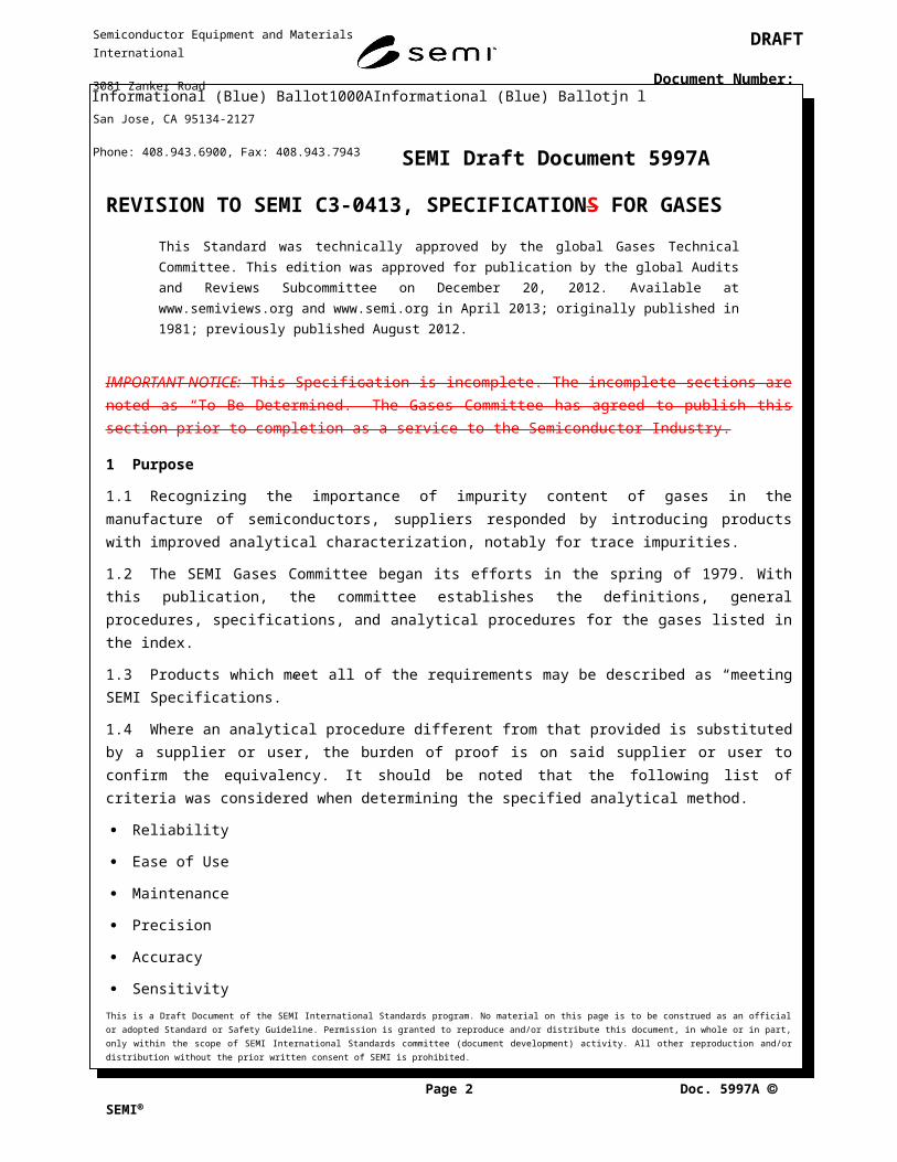
SEMI Draft Document 5997A
REVISION TO SEMI C3-0413, SPECIFICATIONS FOR GASESThis Standard was technically approved by the global Gases Technical Committee. This edition was approved for publication by the global Audits and Reviews Subcommittee on December 20, 2012. Available at www.semiviews.org and www.semi.org in April 2013; originally published in 1981; previously published August 2012.
IMPORTANT NOTICE: This Specification is incomplete. The incomplete sections are noted as “To Be Determined.” The Gases Committee has agreed to publish this section prior to completion as a service to the Semiconductor Industry.
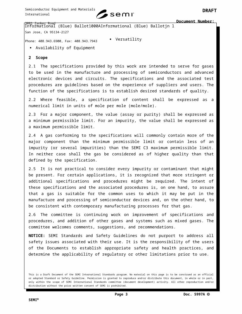
1 Purpose
1.1 Recognizing the importance of impurity content of gases in the manufacture of semiconductors, suppliers responded by introducing products with improved analytical characterization, notably for trace impurities.
1.2 The SEMI Gases Committee began its efforts in the spring of 1979. With this publication, the committee establishes the definitions, general procedures, specifications, and analytical procedures for the gases listed in the index.
1.3 Products which meet all of the requirements may be described as “meeting SEMI Specifications.”
1.4 Where an analytical procedure different from that provided is substituted by a supplier or user, the burden of proof is on said supplier or user to confirm the equivalency. It should be noted that the following list of criteria was considered when determining the specified analytical method.
Reliability
Ease of Use
Maintenance
Precision
Accuracy
Sensitivity
Versatility
Availability of Equipment
2 Scope
2.1 The specifications provided by this work are intended to serve for gases to be used in the manufacture and processing of semiconductors and advanced electronic devices and circuits. The specifications and the associated test procedures are guidelines based on the experience of suppliers and users. The function of the specifications is to establish desired standards of quality.
2.2 Where feasible, a specification of content shall be expressed as a numerical limit in units of mole per mole (mole/mole).
This is a Draft Document of the SEMI International Standards program. No material on this page is to be construed as an official or adopted Standard or Safety Guideline. Permission is granted to reproduce and/or distribute this document, in whole or in part, only within the scope of SEMI International Standards committee (document development) activity. All other reproduction and/or distribution without the prior written consent of SEMI is prohibited.
Page 2 Doc. jn l SEMI
Semiconductor Equipment and Materials International
3081 Zanker Road
San Jose, CA 95134-2127
Phone: 408.943.6900, Fax: 408.943.7943
DRAFT
Document Number:
2.3 For a major component, the value (assay or purity) shall be expressed as a minimum permissible limit. For an impurity, the value shall be expressed as a maximum permissible limit.
2.4 A gas conforming to the specifications will commonly contain more of the major component than the minimum permissible limit or contain less of an impurity (or several impurities) than the SEMI C3 maximum permissible limit. In neither case shall the gas be considered as of higher quality than that defined by the specification.
2.5 It is not practical to consider every impurity or contaminant that might be present. For certain applications, it is recognized that more stringent or additional specifications and procedures might be required. The intent of these specifications and the associated procedures is, on one hand, to assure that a gas is suitable for the common uses to which it may be put in the manufacture and processing of semiconductor devices and, on the other hand, to be consistent with contemporary manufacturing processes for that gas.
2.6 The committee is continuing work on improvement of specifications and procedures, and addition of other gases and systems such as mixed gases. The committee welcomes comments, suggestions, and recommendations.
NOTICE: SEMI Standards and Safety Guidelines do not purport to address all safety issues associated with their use. It is the responsibility of the users of the Documents to establish appropriate safety and health practices, and determine the applicability of regulatory or other limitations prior to use.
3 Referenced Standards and Documents
3.1 United States Military (MIL) Standards1
3.2 MIL-S-27626DF — Sampler, Cryogenic Liquid
NOTICE: Unless otherwise indicated, all documents cited shall be the latest published versions.
4 Terminology
4.1 Abbreviations and Acronyms — In this work, abbreviations used shall be restricted to those listed as follows.
4.1.1 ASTM — ASTM International
4.1.2 atm — atmosphere
4.1.3 BP — boiling point
4.1.4 CGA — Compressed Gas Association
4.1.5 DOT — Department of Transportation (U.S.)
4.1.6 max — maximum
4.1.7 min — minimum
4.1.8 MP — melting point
4.1.9 SCF — standard cubic foot (feet)
4.1.10 temp. — temperature
4.1.11 vol — volume
4.1.12 vol/vol — volume/volume
1 United States Military Standards, Available through the Naval Publications and Forms Center, 5801 Tabor Avenue, Philadelphia, PA 19120-5099, USA; Telephone: 215.697.3321.This is a Draft Document of the SEMI International Standards program. No material on this page is to be construed as an official or adopted Standard or Safety Guideline. Permission is granted to reproduce and/or distribute this document, in whole or in part, only within the scope of SEMI International Standards committee (document development) activity. All other reproduction and/or distribution without the prior written consent of SEMI is prohibited.
Page 3 Doc. jn l SEMI
Semiconductor Equipment and Materials International
3081 Zanker Road
San Jose, CA 95134-2127
Phone: 408.943.6900, Fax: 408.943.7943
DRAFT
Document Number:
4.1.13 wt. — weight
4.1.14 w/v — weight/volume
4.1.15 w/w — weight/weight
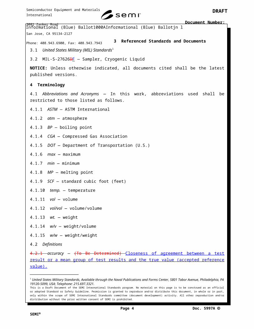
4.2 Definitions
4.2.1 accuracy — (To Be Determined) Closeness of agreement between a test result or a mean group of test results and the true value (accepted reference value).
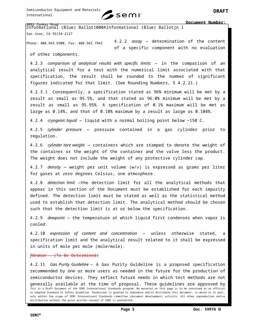
4.2.2 assay — determination of the content of a specific component with no evaluation of other components.
4.2.3 comparison of analytical results with specific limits — in the comparison of an analytical result for a test with the numerical limit associated with that specification, the result shall be rounded to the number of significant figures indicated for that limit. (See Rounding Numbers, § 4.2.21.)
4.2.3.1 Consequently, a specification stated as 96% minimum will be met by a result as small as 95.5%, and that stated as 96.0% minimum will be met by a result as small as 95.95%. A specification of 0.1% maximum will be met as large as 0.14%, and that of 0.10% maximum by a result as large as 0.104%.
4.2.4 cryogenic liquid — liquid with a normal boiling point below −150 C.
4.2.5 cylinder pressure — pressure contained in a gas cylinder prior to regulation.
4.2.6 cylinder tare weight — containers which are stamped to denote the weight of the container or the weight of the container and the valve less the product. The weight does not include the weight of any protective cylinder cap.
4.2.7 density — weight per unit volume (w/v) is expressed as grams per liter for gases at zero degrees Celsius, one atmosphere.
4.2.8 detection limit —the detection limit for all the analytical methods that appear in this section of the Document must be established for each impurity defined. The detection limit must be stated as well as the statistical method used to establish that detection limit. The analytical method should be chosen such that the detection limit is at or below the specification.
4.2.9 dewpoint — the temperature at which liquid first condenses when vapor is cooled.
4.2.10 expression of content and concentration — unless otherwise stated, a specification limit and the analytical result related to it shall be expressed in units of mole per mole (mole/mole).
filtration — (To Be Determined)
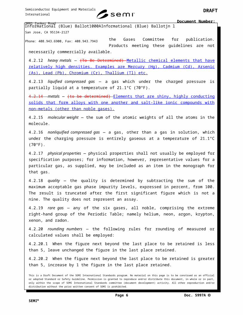
4.2.11 Gas Purity Guideline — A Gas Purity Guideline is a proposed specification recommended by one or more users as needed in the future for the production of semiconductor devices. They reflect future needs in which test methods are not generally available at the time of proposal. These guidelines are approved by the Gases Committee for publication. Products meeting these guidelines are not necessarily commercially available.
4.2.12 heavy metals — (To Be Determined) Metallic chemical elements that have relatively high densities. Examples are Mercury (Hg), Cadmium (Cd), Arsenic (As), Lead (Pb), Chromium (Cr), Thallium (Tl) etc.
4.2.13 liquified compressed gas — a gas which under the charged pressure is partially liquid at a temperature of 21.1°C (70°F).
4.2.14 metals — (to be determined) Elements that are shiny, highly conducting solids that form alloys with one another and salt-like ionic compounds with non-metals (other than noble gases).
4.2.15 molecular weight — the sum of the atomic weights of all the atoms in the molecule.This is a Draft Document of the SEMI International Standards program. No material on this page is to be construed as an official or adopted Standard or Safety Guideline. Permission is granted to reproduce and/or distribute this document, in whole or in part, only within the scope of SEMI International Standards committee (document development) activity. All other reproduction and/or distribution without the prior written consent of SEMI is prohibited.
Page 4 Doc. jn l SEMI
Semiconductor Equipment and Materials International
3081 Zanker Road
San Jose, CA 95134-2127
Phone: 408.943.6900, Fax: 408.943.7943
DRAFT
Document Number:
4.2.16 nonliquified compressed gas — a gas, other than a gas in solution, which under the charging pressure is entirely gaseous at a temperature of 21.1°C (70°F).
4.2.17 physical properties — physical properties shall not usually be employed for specification purposes; for information, however, representative values for a particular gas, as supplied, may be included as an item in the monograph for that gas.
4.2.18 quality — the quality is determined by subtracting the sum of the maximum acceptable gas phase impurity levels, expressed in percent, from 100. The result is truncated after the first significant figure which is not a nine. The quality does not represent an assay.
4.2.19 rare gas — any of the six gases, all noble, comprising the extreme right-hand group of the Periodic Table; namely helium, neon, argon, krypton, xenon, and radon.
4.2.20 rounding numbers — the following rules for rounding of measured or calculated values shall be employed:
4.2.20.1 When the figure next beyond the last place to be retained is less than 5, leave unchanged the figure in the last place retained.
4.2.20.2 When the figure next beyond the last place to be retained is greater than 5, increase by 1 the figure in the last place retained.
4.2.20.3 When the figure next beyond the last place to be retained is 5 and there are no figures beyond this 5 or only zeroes, (a) increase by 1 the figure in the last place retained if it is odd, or (b) leave the figure unchanged if it is even.
4.2.20.4 When the figure next beyond the last place to be retained is 5 and there are figures other than zeroes beyond this 5, increase by 1 the figure in the last place retained.
4.2.20.5 Obtain the rounded value in one step by direct rounding and not in two or more steps of successive rounding.
4.2.21 specific gravity — the ratio of the mass of a gas to the mass of an equal volume of air at a specified temperature. For liquids, it is the ratio of the mass of the liquid to the mass of an equal volume of water.
4.2.22 specification and specification limits — the specification limit should fall above or in the range of the result and its uncertainty.
4.2.23 temperature — temperature values shall be expressed in degrees Celsius.
4.2.24 tolerances in measurements — use the following guidelines for mixture tolerances:
4.2.24.1 Mixtures should be specified by the major component and the concentration of the desired minor component(s).
4.2.24.2 All component gases shall adhere to the appropriate SEMI Specification, if available.
4.2.24.3 The impurity levels in the mixture shall not exceed the algebraic sum of the impurities specified for the designated components.
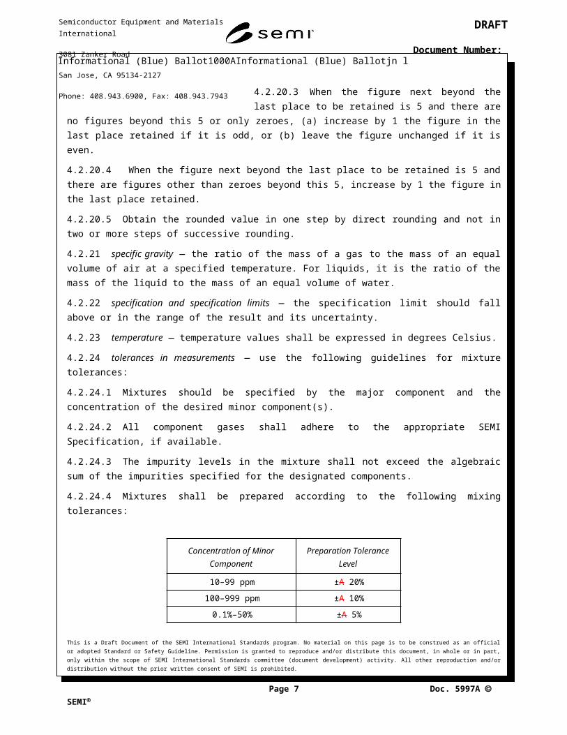
4.2.24.4 Mixtures shall be prepared according to the following mixing tolerances:
Concentration of Minor Component Preparation Tolerance Level
10–99 ppm ±A 20%
100–999 ppm ±A 10%
This is a Draft Document of the SEMI International Standards program. No material on this page is to be construed as an official or adopted Standard or Safety Guideline. Permission is granted to reproduce and/or distribute this document, in whole or in part, only within the scope of SEMI International Standards committee (document development) activity. All other reproduction and/or distribution without the prior written consent of SEMI is prohibited.
Page 5 Doc. jn l SEMI
Semiconductor Equipment and Materials International
3081 Zanker Road
San Jose, CA 95134-2127
Phone: 408.943.6900, Fax: 408.943.7943
DRAFT
Document Number:
0.1%–50% ±A 5%
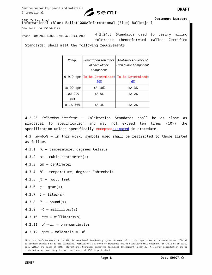
4.2.24.5 Standards used to verify mixing tolerance (henceforward called Certified Standards) shall meet the following requirements:
Range Preparation Tolerance of Each Minor Component
Analytical Accuracy of Each Minor Component
0–9.9 ppm To Be Determined± 20% To Be Determined± 6%
10–99 ppm ±A 10% ±A 3%
100–999 ppm ±A 5% ±A 2%
0.1%–50% ±A 4% ±A 2%
4.2.25 Calibration Standards — Calibration Standards shall be as close as practical to specification and may not exceed ten times (10×) the specification unless specifically exceptedexempted in procedure.
4.3 Symbols — In this work, symbols used shall be restricted to those listed as follows.
4.3.1 °C — temperature, degrees Celsius
4.3.2 cc — cubic centimeter(s)
4.3.3 cm — centimeter
4.3.4 °F — temperature, degrees Fahrenheit
4.3.5 ft. — foot, feet
4.3.6 g — gram(s)
4.3.7 L — liter(s)
4.3.8 lb. — pound(s)
4.3.9 mL — milliliter(s)
4.3.10 mm — millimeter(s)
4.3.11 ohm-cm — ohm-centimeter
4.3.12 ppm — mole/mole × 106
4.3.13 ppb — mole/mole × 109
4.3.14 ppba — mole/mole × 109 atomic
4.3.15 ppbw — weight/weight × 109
4.3.16 psia — pounds per square inch absolute
4.3.17 psig — pounds per square inch gauge
4.3.18 Mw — molecular weight (g/mole)
This is a Draft Document of the SEMI International Standards program. No material on this page is to be construed as an official or adopted Standard or Safety Guideline. Permission is granted to reproduce and/or distribute this document, in whole or in part, only within the scope of SEMI International Standards committee (document development) activity. All other reproduction and/or distribution without the prior written consent of SEMI is prohibited.
Page 6 Doc. jn l SEMI
Semiconductor Equipment and Materials International
3081 Zanker Road
San Jose, CA 95134-2127
Phone: 408.943.6900, Fax: 408.943.7943
DRAFT
Document Number:
5 Samples
5.1 Sample Size — The quantity of gas/liquid in a single sample container shall be sufficient to perform the analysis for all the listed specifications. If a single sample does not contain a sufficient quantity of gas/liquid to perform all of the required analyses, additional samples from the same source shall be taken under similar conditions.
5.2 Gaseous Samples — Gaseous samples shall be representative of the gaseous supply. Sampling shall be performed in accordance with one of the following:
5.2.1 By withdrawing a sample from the supply container through a suitable connection into the sample container. (For safety reasons, the sample container and sampling system must have a rated service pressure at least equal to the pressure in the supply container.)
5.2.2 By connecting the container being sampled directly to the analytical equipment.
5.2.3 By selecting a representative cylinder from the cylinders in the lot.
5.3 Liquid Sampling (Vaporized) — Vaporized liquid samples shall be representative of the liquid supply. Sampling shall be in accordance with one of the following:
5.3.1 By vaporizing liquid from the supply container in the sample tubing.
5.3.2 By flowing liquid from the supply container into, or through, a suitable container in which a representative sample is collected and then vaporized.
5.4 Liquid Samples (Liquified Compressed Gases) — A direct connection between the liquid phase of liquified compressed gas containers and the analytical equipment can be achieved, provided suitable flash vaporization is obtained.
5.5 Lot Acceptance Tests — These are analyses performed on the gas/liquid in the shipping container, or a sample thereof, which is representative of the lot. (The terms ‘lot’ and ‘batch’ may be used interchangeably.)
5.6 Lots — One of the following is to be used:
5.6.1 No specific quantity or any quantity of product agreed upon between the supplier and the customer.
5.6.2 All of the product supplied during the contract period.
5.6.3 All of the product supplied or containers filled during a calendar month.
5.6.4 All of the product supplied or containers filled during seven consecutive days.
5.6.5 All of the product supplied or containers filled during a consecutive 24-hour period.
5.6.6 All of the product supplied or containers filled during one eight-hour shift.
5.6.7 All of the product supplied in one shipment.
5.6.8 All of the product supplied in one shipping container.
5.6.9 All of the product supplied in the container(s) filled on one manifold at the same time.
5.7 Number of Samples Per Lot — The number of samples per lot shall be in accordance with one of the following:
5.7.1 One sample per lot.
5.7.2 Any number of samples agreed upon by the supplier and the customer.
This is a Draft Document of the SEMI International Standards program. No material on this page is to be construed as an official or adopted Standard or Safety Guideline. Permission is granted to reproduce and/or distribute this document, in whole or in part, only within the scope of SEMI International Standards committee (document development) activity. All other reproduction and/or distribution without the prior written consent of SEMI is prohibited.
Page 7 Doc. jn l SEMI
Semiconductor Equipment and Materials International
3081 Zanker Road
San Jose, CA 95134-2127
Phone: 408.943.6900, Fax: 408.943.7943
DRAFT
Document Number:
6 Sampling
6.1 For gases provided in cylinders, a sample can be taken directly for analysis. For gases provided in bulk quantities or cylinders where direct sampling is not appropriate, a sample may be taken per SEMI sampling procedures.
6.2 Sampling Procedures
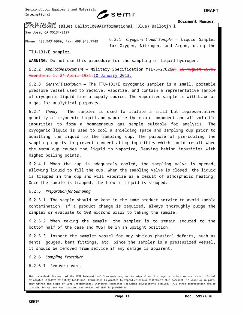
6.2.1 Cryogenic Liquid Sample — Liquid Samples for Oxygen, Nitrogen, and Argon, using the TTU-131/E sampler.
WARNING: Do not use this procedure for the sampling of liquid hydrogen.
6.2.2 Applicable Document — Military Specification MIL-S-27626DF 16 August 1979, Amendment 1, 24 April 1981.10 January 2013.
6.2.3 General Description — The TTU-131/E cryogenic sampler is a small, portable pressure vessel used to receive, vaporize, and contain a representative sample of cryogenic liquid from a supply source. The vaporized sample is withdrawn as a gas for analytical purposes.
6.2.4 Theory — The sampler is used to isolate a small but representative quantity of cryogenic liquid and vaporize the major component and all volatile impurities to form a homogeneous gas sample suitable for analysis. The cryogenic liquid is used to cool a shielding space and sampling cup prior to admitting the liquid to the sampling cup. The purpose of pre-cooling the sampling cup is to prevent concentrating impurities which could result when the warm cup causes the liquid to vaporize, leaving behind impurities with higher boiling points.
6.2.4.1 When the cup is adequately cooled, the sampling valve is opened, allowing liquid to fill the cup. When the sampling valve is closed, the liquid is trapped in the cup and will vaporize as a result of atmospheric heating. Once the sample is trapped, the flow of liquid is stopped.
6.2.5 Preparation for Sampling
6.2.5.1 The sample should be kept in the same product service to avoid sample contamination. If a product change is required, always thoroughly purge the sampler or evacuate to 100 microns prior to taking the sample.
6.2.5.2 When taking the sample, the sampler is to remain secured to the bottom half of the case and MUST be in an upright position.
6.2.5.3 Inspect the sampler vessel for any obvious physical defects, such as dents, gouges, bent fittings, etc. Since the sampler is a pressurized vessel, it should be removed from service if any damage is apparent.
6.2.6 Sampling Procedure
6.2.6.1 Remove cover.
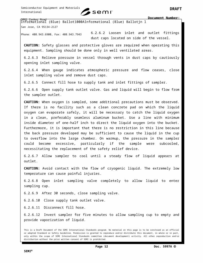
6.2.6.2 Loosen inlet and outlet fittings dust caps located on side of the vessel.
CAUTION: Safety glasses and protective gloves are required when operating this equipment. Sampling should be done only in well ventilated areas.
6.2.6.3 Relieve pressure in vessel through vents in dust caps by cautiously opening inlet sampling valve.
6.2.6.4 When gauge indicates atmospheric pressure and flow ceases, close inlet sampling valve and remove dust caps.
6.2.6.5 Connect fill hose to supply tank and inlet fittings of sampler.
6.2.6.6 Open supply tank outlet valve. Gas and liquid will begin to flow from the sampler outlet.This is a Draft Document of the SEMI International Standards program. No material on this page is to be construed as an official or adopted Standard or Safety Guideline. Permission is granted to reproduce and/or distribute this document, in whole or in part, only within the scope of SEMI International Standards committee (document development) activity. All other reproduction and/or distribution without the prior written consent of SEMI is prohibited.
Page 8 Doc. jn l SEMI
Semiconductor Equipment and Materials International
3081 Zanker Road
San Jose, CA 95134-2127
Phone: 408.943.6900, Fax: 408.943.7943
DRAFT
Document Number:
CAUTION: When oxygen is sampled, some additional precautions must be observed. If there is no facility such as a clean concrete pad on which the liquid oxygen can evaporate safely, it will be necessary to catch the liquid oxygen in a clean, preferably seamless aluminum bucket. Use a line with minimum inside diameter of one-half inch to direct the liquid oxygen into the bucket. Furthermore, it is important that there is no restriction in this line because the back pressure developed may be sufficient to cause the liquid in the cup to overflow into the large chamber. On warmup, the pressure in the sampler could become excessive, particularly if the sample were subcooled, necessitating the replacement of the safety relief device.
6.2.6.7 Allow sampler to cool until a steady flow of liquid appears at outlet.
CAUTION: Avoid contact with the flow of cryogenic liquid. The extremely low temperature can cause painful injuries.
6.2.6.8 Open inlet sampling valve completely to allow liquid to enter sampling cup.
6.2.6.9 After 30 seconds, close sampling valve.
6.2.6.10 Close supply tank outlet valve.
6.2.6.11 Disconnect fill hose.
6.2.6.12 Invert sampler for five minutes to allow sampling cup to empty and provide vaporization of liquid.
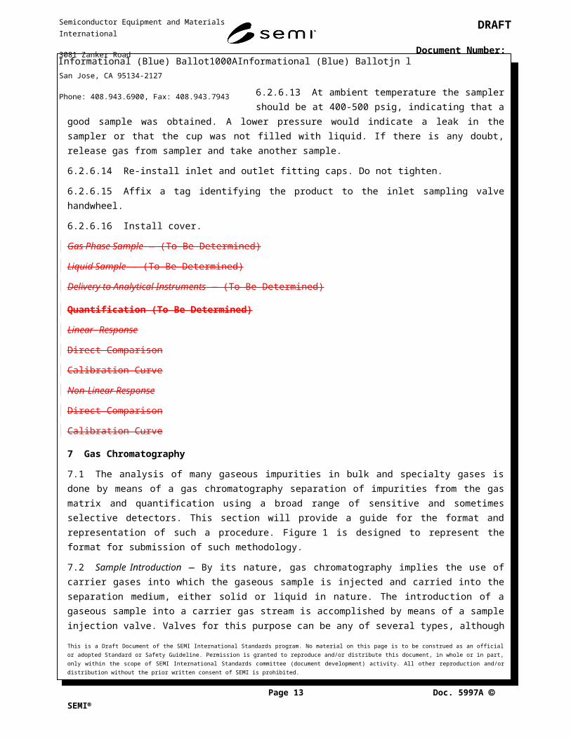
6.2.6.13 At ambient temperature the sampler should be at 400-500 psig, indicating that a good sample was obtained. A lower pressure would indicate a leak in the sampler or that the cup was not filled with liquid. If there is any doubt, release gas from sampler and take another sample.
6.2.6.14 Re-install inlet and outlet fitting caps. Do not tighten.
6.2.6.15 Affix a tag identifying the product to the inlet sampling valve handwheel.
6.2.6.16 Install cover.
Gas Phase Sample — (To Be Determined)
Liquid Sample — (To Be Determined)
Delivery to Analytical Instruments — (To Be Determined)
Quantification (To Be Determined)
Linear Response
Direct Comparison
Calibration Curve
Non-Linear Response
Direct Comparison
Calibration Curve
7 Gas Chromatography
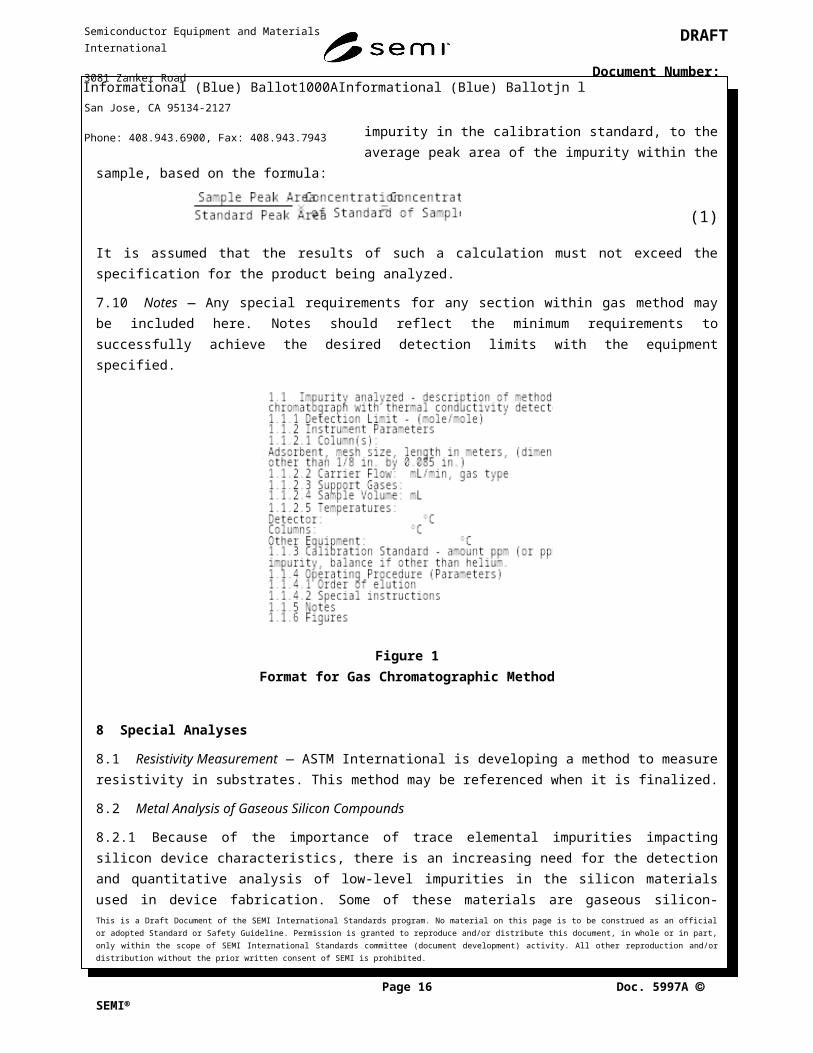
7.1 The analysis of many gaseous impurities in bulk and specialty gases is done by means of a gas chromatography separation of impurities from the gas matrix and quantification using a broad range of sensitive and sometimes selective detectors. This section will provide a guide for the format and representation of such a procedure. Figure 1 is designed to represent the format for submission of such methodology.
This is a Draft Document of the SEMI International Standards program. No material on this page is to be construed as an official or adopted Standard or Safety Guideline. Permission is granted to reproduce and/or distribute this document, in whole or in part, only within the scope of SEMI International Standards committee (document development) activity. All other reproduction and/or distribution without the prior written consent of SEMI is prohibited.
Page 9 Doc. jn l SEMI
Semiconductor Equipment and Materials International
3081 Zanker Road
San Jose, CA 95134-2127
Phone: 408.943.6900, Fax: 408.943.7943
DRAFT
Document Number:
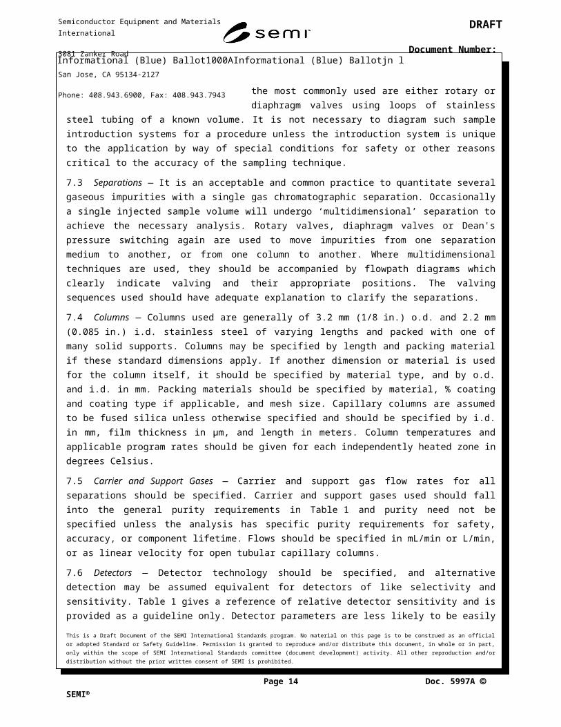
7.2 Sample Introduction — By its nature, gas chromatography implies the use of carrier gases into which the gaseous sample is injected and carried into the separation medium, either solid or liquid in nature. The introduction of a gaseous sample into a carrier gas stream is accomplished by means of a sample injection valve. Valves for this purpose can be any of several types, although the most commonly used are either rotary or diaphragm valves using loops of stainless steel tubing of a known volume. It is not necessary to diagram such sample introduction systems for a procedure unless the introduction system is unique to the application by way of special conditions for safety or other reasons critical to the accuracy of the sampling technique.
7.3 Separations — It is an acceptable and common practice to quantitate several gaseous impurities with a single gas chromatographic separation. Occasionally a single injected sample volume will undergo ‘multidimensional’ separation to achieve the necessary analysis. Rotary valves, diaphragm valves or Dean's pressure switching again are used to move impurities from one separation medium to another, or from one column to another. Where multidimensional techniques are used, they should be accompanied by flowpath diagrams which clearly indicate valving and their appropriate positions. The valving sequences used should have adequate explanation to clarify the separations.
7.4 Columns — Columns used are generally of 3.2 mm (1/8 in.) o.d. and 2.2 mm (0.085 in.) i.d. stainless steel of varying lengths and packed with one of many solid supports. Columns may be specified by length and packing material if these standard dimensions apply. If another dimension or material is used for the column itself, it should be specified by material type, and by o.d. and i.d. in mm. Packing materials should be specified by material, % coating and coating type if applicable, and mesh size. Capillary columns are assumed to be fused silica unless otherwise specified and should be specified by i.d. in mm, film thickness in µm, and length in meters. Column temperatures and applicable program rates should be given for each independently heated zone in degrees Celsius.
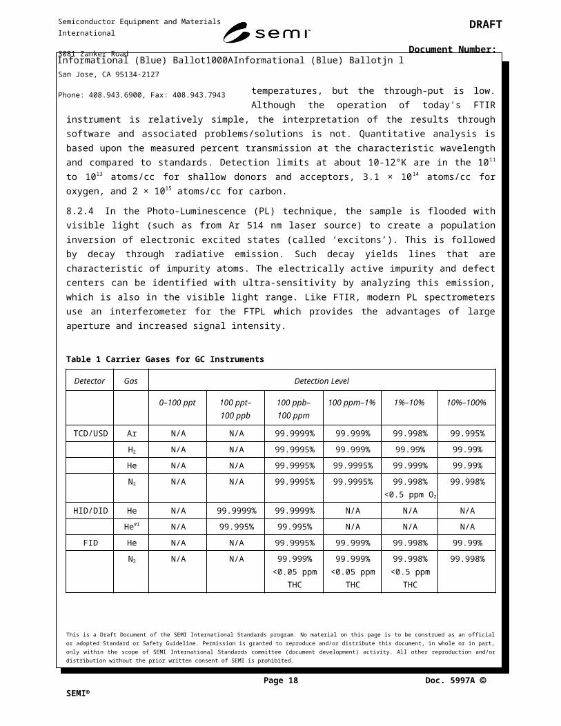
7.5 Carrier and Support Gases — Carrier and support gas flow rates for all separations should be specified. Carrier and support gases used should fall into the general purity requirements in Table 1 and purity need not be specified unless the analysis has specific purity requirements for safety, accuracy, or component lifetime. Flows should be specified in mL/min or L/min, or as linear velocity for open tubular capillary columns.
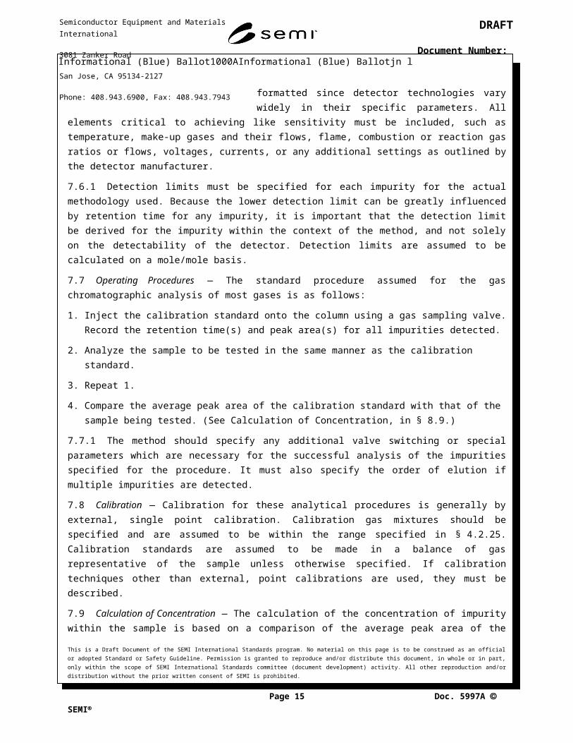
7.6 Detectors — Detector technology should be specified, and alternative detection may be assumed equivalent for detectors of like selectivity and sensitivity. Table 1 gives a reference of relative detector sensitivity and is provided as a guideline only. Detector parameters are less likely to be easily formatted since detector technologies vary widely in their specific parameters. All elements critical to achieving like sensitivity must be included, such as temperature, make-up gases and their flows, flame, combustion or reaction gas ratios or flows, voltages, currents, or any additional settings as outlined by the detector manufacturer.
7.6.1 Detection limits must be specified for each impurity for the actual methodology used. Because the lower detection limit can be greatly influenced by retention time for any impurity, it is important that the detection limit be derived for the impurity within the context of the method, and not solely on the detectability of the detector. Detection limits are assumed to be calculated on a mole/mole basis.
7.7 Operating Procedures — The standard procedure assumed for the gas chromatographic analysis of most gases is as follows:
1. Inject the calibration standard onto the column using a gas sampling valve. Record the retention time(s) and peak area(s) for all impurities detected.
2. Analyze the sample to be tested in the same manner as the calibration standard.
3. Repeat 1.
This is a Draft Document of the SEMI International Standards program. No material on this page is to be construed as an official or adopted Standard or Safety Guideline. Permission is granted to reproduce and/or distribute this document, in whole or in part, only within the scope of SEMI International Standards committee (document development) activity. All other reproduction and/or distribution without the prior written consent of SEMI is prohibited.
Page 10 Doc. jn l SEMI
Semiconductor Equipment and Materials International
3081 Zanker Road
San Jose, CA 95134-2127
Phone: 408.943.6900, Fax: 408.943.7943
DRAFT
Document Number:
4. Compare the average peak area of the calibration standard with that of the sample being tested. (See Calculation of Concentration, in § 8.9.)
7.7.1 The method should specify any additional valve switching or special parameters which are necessary for the successful analysis of the impurities specified for the procedure. It must also specify the order of elution if multiple impurities are detected.
7.8 Calibration — Calibration for these analytical procedures is generally by external, single point calibration. Calibration gas mixtures should be specified and are assumed to be within the range specified in § 4.2.25. Calibration standards are assumed to be made in a balance of gas representative of the sample unless otherwise specified. If calibration techniques other than external, point calibrations are used, they must be described.
7.9 Calculation of Concentration — The calculation of the concentration of impurity within the sample is based on a comparison of the average peak area of the impurity in the calibration standard, to the average peak area of the impurity within the sample, based on the formula:
(1)
It is assumed that the results of such a calculation must not exceed the specification for the product being analyzed.
7.10 Notes — Any special requirements for any section within gas method may be included here. Notes should reflect the minimum requirements to successfully achieve the desired detection limits with the equipment specified.
Figure 1Format for Gas Chromatographic Method
8 Special Analyses
8.1 Resistivity Measurement — ASTM International is developing a method to measure resistivity in substrates. This method may be referenced when it is finalized.
8.2 Metal Analysis of Gaseous Silicon Compounds
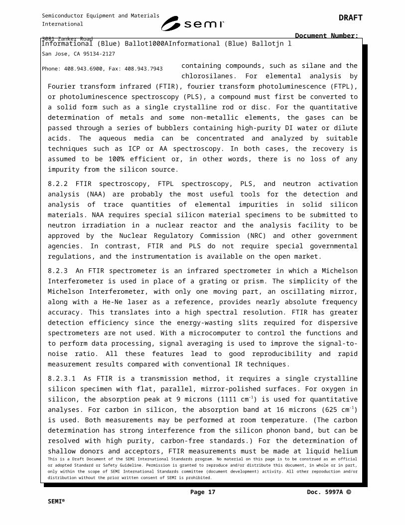
8.2.1 Because of the importance of trace elemental impurities impacting silicon device characteristics, there is an increasing need for the detection and quantitative analysis of low-level impurities in the silicon materials used in device fabrication. Some of these materials are gaseous silicon-containing compounds, such as silane and the This is a Draft Document of the SEMI International Standards program. No material on this page is to be construed as an official or adopted Standard or Safety Guideline. Permission is granted to reproduce and/or distribute this document, in whole or in part, only within the scope of SEMI International Standards committee (document development) activity. All other reproduction and/or distribution without the prior written consent of SEMI is prohibited.
Page 11 Doc. jn l SEMI
Semiconductor Equipment and Materials International
3081 Zanker Road
San Jose, CA 95134-2127
Phone: 408.943.6900, Fax: 408.943.7943
DRAFT
Document Number:
chlorosilanes. For elemental analysis by Fourier transform infrared (FTIR), fourier transform photoluminescence (FTPL), or photoluminescence spectroscopy (PLS), a compound must first be converted to a solid form such as a single crystalline rod or disc. For the quantitative determination of metals and some non-metallic elements, the gases can be passed through a series of bubblers containing high-purity DI water or dilute acids. The aqueous media can be concentrated and analyzed by suitable techniques such as ICP or AA spectroscopy. In both cases, the recovery is assumed to be 100% efficient or, in other words, there is no loss of any impurity from the silicon source.
8.2.2 FTIR spectroscopy, FTPL spectroscopy, PLS, and neutron activation analysis (NAA) are probably the most useful tools for the detection and analysis of trace quantities of elemental impurities in solid silicon materials. NAA requires special silicon material specimens to be submitted to neutron irradiation in a nuclear reactor and the analysis facility to be approved by the Nuclear Regulatory Commission (NRC) and other government agencies. In contrast, FTIR and PLS do not require special governmental regulations, and the instrumentation is available on the open market.
8.2.3 An FTIR spectrometer is an infrared spectrometer in which a Michelson Interferometer is used in place of a grating or prism. The simplicity of the Michelson Interferometer, with only one moving part, an oscillating mirror, along with a He-Ne laser as a reference, provides nearly absolute frequency accuracy. This translates into a high spectral resolution. FTIR has greater detection efficiency since the energy-wasting slits required for dispersive spectrometers are not used. With a microcomputer to control the functions and to perform data processing, signal averaging is used to improve the signal-to-noise ratio. All these features lead to good reproducibility and rapid measurement results compared with conventional IR techniques.
8.2.3.1 As FTIR is a transmission method, it requires a single crystalline silicon specimen with flat, parallel, mirror-polished surfaces. For oxygen in silicon, the absorption peak at 9 microns (1111 cm-1) is used for quantitative analyses. For carbon in silicon, the absorption band at 16 microns (625 cm-1) is used. Both measurements may be performed at room temperature. (The carbon determination has strong interference from the silicon phonon band, but can be resolved with high purity, carbon-free standards.) For the determination of shallow donors and acceptors, FTIR measurements must be made at liquid helium temperatures, but the through-put is low. Although the operation of today's FTIR instrument is relatively simple, the interpretation of the results through software and associated problems/solutions is not. Quantitative analysis is based upon the measured percent transmission at the characteristic wavelength and compared to standards. Detection limits at about 10-12°K are in the 10 11 to 1013 atoms/cc for shallow donors and acceptors, 3.1 × 10¹⁴ atoms/cc for oxygen, and 2 × 10¹⁵ atoms/cc for carbon.
8.2.4 In the Photo-Luminescence (PL) technique, the sample is flooded with visible light (such as from Ar 514 nm laser source) to create a population inversion of electronic excited states (called ‘excitons’). This is followed by decay through radiative emission. Such decay yields lines that are characteristic of impurity atoms. The electrically active impurity and defect centers can be identified with ultra-sensitivity by analyzing this emission, which is also in the visible light range. Like FTIR, modern PL spectrometers use an interferometer for the FTPL which provides the advantages of large aperture and increased signal intensity.
Table 1 Carrier Gases for GC Instruments
Detector Gas Detection Level
0–100 ppt 100 ppt–100 ppb
100 ppb–100 ppm
100 ppm–1% 1%–10% 10%–100%
TCD/USD Ar N/A N/A 99.9999% 99.999% 99.998% 99.995%
H2 N/A N/A 99.9995% 99.999% 99.99% 99.99%
This is a Draft Document of the SEMI International Standards program. No material on this page is to be construed as an official or adopted Standard or Safety Guideline. Permission is granted to reproduce and/or distribute this document, in whole or in part, only within the scope of SEMI International Standards committee (document development) activity. All other reproduction and/or distribution without the prior written consent of SEMI is prohibited.
Page 12 Doc. jn l SEMI
Semiconductor Equipment and Materials International
3081 Zanker Road
San Jose, CA 95134-2127
Phone: 408.943.6900, Fax: 408.943.7943
DRAFT
Document Number:
Detector Gas Detection Level
0–100 ppt 100 ppt–100 ppb
100 ppb–100 ppm
100 ppm–1% 1%–10% 10%–100%
He N/A N/A 99.9995% 99.9995% 99.999% 99.99%
N2 N/A N/A 99.9995% 99.9995% 99.998%<0.5 ppm O2
99.998%
HID/DID He N/A 99.9999% 99.9999% N/A N/A N/A
He#1 N/A 99.995% 99.995% N/A N/A N/A
FID He N/A N/A 99.9995% 99.999% 99.998% 99.99%
N2 N/A N/A 99.999%<0.05 ppm
THC
99.999%<0.05 ppm
THC
99.998%<0.5 ppm THC
99.998%
H2#2 N/A N/A 99.9995%
<0.2 ppm THC99.999%
<0.5 ppm THC99.99%
<0.5 ppm THC99.99%
Air#2 N/A N/A HC Free<0.1 ppm THC
Zero Air<1 ppm THC
Zero Air<1 ppm THC
Blended Air
FPD He N/A 99.9995% 99.999% N/A N/A N/A
N2 N/A 99.999%<0.05 THC
99.998%<0.5 ppm THC
N/A N/A N/A
H2#2 N/A 99.995%
<0.2 ppm THC99.999%
<0.5 ppm THCN/A N/A N/A
Air#2 N/A HC Free<0.1 ppm THC
Zero Air<1 ppm THC
N/A N/A N/A
RGD Ar 99.999%<1 ppm H2/CO
99.999%<1 ppm H2/CO
99.999%<1 ppm H2/CO
99.999%<1 ppm H2/CO
N/A N/A
N2 99.999%<1 ppm H2/CO
99.999%<1 ppm H2/CO
99.999%<1 ppm H2/CO
99.999%<1 ppm H2/CO
N/A N/A
Air Zero Air<1 ppm H2/CO
Zero Air<1 ppm H2/CO
Zero Air<1 ppm H2/CO
Zero Air<1 ppm H2/CO
N/A N/A
ECD N2 99.9995% 99.998%<0.5 ppm O2
99.998%<0.5 ppm O2
N/A N/A N/A
CH4/Ar EC Grade<1 ppb Total Halocarbons
EC Grade<1 ppb Total Halocarbons
EC Grade<1 ppb Total Halocarbons
N/A N/A N/A
PID He N/A 99.9995% 99.995% N/A N/A N/A
N2 N/A 99.9995% 99.998% N/A N/A N/A
MS/MSD H2 99.9995%<0.2 ppm THC
99.999%<0.5 ppm THC
99.999%<0.5 ppm THC
99.99%<0.5 ppm THC
99.99%<0.5 ppm THC
99.99%<0.5 ppm THC
Ar 99.999% 99.998% 99.998% 99.998% 99.998% 99.998%
He 99.9995% 99.999% 99.999% 99.995% 99.995% 99.995%
N2 99.9995% 99.998% 99.998% 99.998% 99.998% 99.998%
#1 Purge gas.
#2 Combustion gases
This is a Draft Document of the SEMI International Standards program. No material on this page is to be construed as an official or adopted Standard or Safety Guideline. Permission is granted to reproduce and/or distribute this document, in whole or in part, only within the scope of SEMI International Standards committee (document development) activity. All other reproduction and/or distribution without the prior written consent of SEMI is prohibited.
Page 13 Doc. jn l SEMI
Semiconductor Equipment and Materials International
3081 Zanker Road
San Jose, CA 95134-2127
Phone: 408.943.6900, Fax: 408.943.7943
DRAFT
Document Number:
Table 2 Detectors for Gas Chromatography
Detector Type Temp Limit
Analytes Analyzed#1
Carrier Gases Selectivity Detectability LinearRange
Thermal Conductivity (TCD)
U 400 CF4, PH3, SF6, Fixed
Gases
He, H2, Ar, N2 N/A 4 × 10⁻¹⁰ g/mL >105
Ultrasonic (USD) U CO2, O2, N2, CO
He, H2, Ar, O2, N2, Air
N/A 1 × 10⁻⁹ g/mL 106
Helium Ionization (HID)
U 325 H2, O2, Ar, N2, CO
He N/A 4 × 10-14 g/mL 104
Discharge Ionization (DID)
U same as HID He N/A 1 × 10-12 g/mL 104
Flame Ionization (FID)
S 420 C1-C5, CxFy, CxClyFz, CO,
CO2
H2/Air#2, He, N2, H2
Hydrocarbons 2 × 10-12 g/sec >107
Flame Photometric (FPD)
S 420 H2S H2/Air#2, He, N2, H2
S/C 103-106:1 P/C > 105:1
S<1 × 10-11 g/mLP<1 × 10-12 g/mL
S ≥ 103
P ≥ 104
Reduction Gas (RGD)
S 300 CO, H2 N2, Ar, He, Air H2, CO H2 0.5 − 2 ppbCO 0.5 − 4 ppb
103-104
Electron Capture
(ECD) (Ni63)
S 420 N2, P5 halogens 5 × 10-15 g 104
(linearized)
Photoionization (PID)
S 350 PH3, H2S, AsH3
Ar, H2, N2 By ionization energy
2 × 10-13 g/sec >107
Thermionic (TID) S 420 H2, 8% H2/He N/P 1:5N/C 5 × 10⁴:1
P/C 105:1
N 1 × 10-13 g/secP 5 × 10-14 g/sec
105
Mass Spectroscopy (MS)
S 320 He, H2 variable with mass range
EI: 10-100 pgNICI: variable as low
as 25 fg
105-106
Mass Density (MSD) S
Atomospheric Pressure Mass Spectroscopy
(APIMS)
#1 This does not represent detector capability; rather those analytes analyzed by current SEMI procedures.
#2 Used as combustion gases.
8.2.5 PLS of single crystalline silicon specimens at liquid helium temperatures exhibits sharp emission lines. Electron hole pairs called excitons are formed by incident radiation (514.5 nm line from argon laser). The decay of these ‘exciton or multi-exciton’ states yields the lines characteristic of the impurity atoms. For elemental detection, the observed emission lines must be assigned as being extrinsic (due to impurities) or intrinsic (due to silicon). The luminescence process itself appears too complex to attain precision or accuracy from basic calculations. The PLS emissions are analyzed as a function of wavelength, suggested to be 1077 to 1139 nm, for the elemental determination of shallow donors and acceptors in silicon. Quantitative measurements of impurities are based on the This is a Draft Document of the SEMI International Standards program. No material on this page is to be construed as an official or adopted Standard or Safety Guideline. Permission is granted to reproduce and/or distribute this document, in whole or in part, only within the scope of SEMI International Standards committee (document development) activity. All other reproduction and/or distribution without the prior written consent of SEMI is prohibited.
Page 14 Doc. jn l SEMI
Semiconductor Equipment and Materials International
3081 Zanker Road
San Jose, CA 95134-2127
Phone: 408.943.6900, Fax: 408.943.7943
DRAFT
Document Number:
extrinsic-to-intrinsic intensity ratio and compared to standards. The PLS emissions are analyzed using a monochromator and detected by a photomultiplier. Sensitivity in the range of 5 × 10¹⁰ to 5 × 10¹¹ atoms/cc has been claimed for B, Al, P, and As.
8.2.5.1 In order to obtain reliable measurements, the silicon specimens must be in single crystalline form with a mirrored surface. Epitaxial wafers with layers of thickness greater than 10 microns are suitable, since the sample's depth appears to be less than 5 microns. However, it is still in the development stage, and very few laboratories have such capability. A number of questions remain unanswered, including the following:
1. What is the effect of compensating impurities?
2. What is the effect of deep levels and intracenter transitions on the intensity ratios?
3. What is the effect of crystallographic defects? Of point defects? And of surface defects?
4. Interference from other shallow impurities may mask the detection of very low-level impurities. For instance, PLS signal of Al at 1078.5 nm may be affected by strong signals from As at 1079.0 nm or at 1078.2 nm.
8.2.5.2 CVD-deposited films in single crystalline form can be used for elemental detection of donors and acceptors for gaseous silicon compounds. However, PLS does not detect carbon, oxygen, or nitrogen. It is also not useful for metallic impurities. That is, in general, PLS is useful only for a very limited number of impurities.
8.2.6 Based on this analysis, it was recommended that the SEMI Gases Committee should wait for further development of innovative and improved analytical techniques for the quantitative determination of low-level elemental impurities based on FTIR and PLS. Meanwhile, techniques such as ICP, AA, and Ion Chromatography may be applicable to a very large number of impurities of interest to the silicon semiconductor industry. Development and adaptation of these technologies should be encouraged.
8.2.7 Atomic absorption (AA) spectrophotometry, inductively coupled plasma (ICP) emission spectrometry, and ion chromatography (IC) are probably the most valuable instrumental techniques for the detection and analysis of trace elemental impurities in aqueous media. These techniques usually require that the elements be dissolved in an aqueous medium. Due to this fact, and the fact that the elemental impurities are typically present in silane and the chlorosilanes at the ppb and sub-ppb levels (which is beyond the detection limits for these techniques for most elements) it is usually necessary to concentrate the impurities prior to analysis, such as by passing the gas through a series of impingers (i.e., gas bubblers) containing either DI water or, more commonly, acidic solutions. From analyses of the impinger solutions together with knowledge concerning impinger solution volume(s) and both the flow rate and period of flow of the gas, the concentration of the respective elements in the original gas should be readily calculated to a fairly high degree of accuracy.
8.2.7.1 Atomic absorption spectrophotometry can be used for elemental analyses for a multitude of elements in the periodic table at detection limits ranging from ppm to ppb, depending both on the exact configuration or setup and the element being analyzed. The principle of the technique involves conversion of an incoming aerosol into an atomic vapor which can absorb light from a primary light source, usually a hollow cathode lamp or an electrodeless discharge lamp (EDL), the latter providing improved sensitivity and lower detection limits for certain elements. In addition, a flameless (i.e., graphite furnace) technique can be used to increase sensitivities and detection limits 50 to 100 times better.
8.2.7.2 Complementary to atomic absorption spectrophotometry is flame emission spectrophotometry, which differs in the absence of a primary light source. Again, a flame is utilized to convert an incoming aerosol into an atomic vapor. However, the flame also thermally elevates the atoms to an excited electronic state, and, when the atoms return to the ground state, they emit light detectable by a photomultiplier. This technique is ideal for the analysis of Li, Ha, and K at ppm and sub-ppm levels.
This is a Draft Document of the SEMI International Standards program. No material on this page is to be construed as an official or adopted Standard or Safety Guideline. Permission is granted to reproduce and/or distribute this document, in whole or in part, only within the scope of SEMI International Standards committee (document development) activity. All other reproduction and/or distribution without the prior written consent of SEMI is prohibited.
Page 15 Doc. jn l SEMI
Semiconductor Equipment and Materials International
3081 Zanker Road
San Jose, CA 95134-2127
Phone: 408.943.6900, Fax: 408.943.7943
DRAFT
Document Number:
8.2.7.3 Inductively coupled plasma emission spectrometry is rapidly replacing atomic absorption spectrophotometry for elemental analyses of liquids, since approximately 70% of the elements in the periodic table can be determined with better precision and equal or better sensitivity with minimal sample preparation. Detection limits, in fact, for this technique range from ppm to sub-ppb levels, depending both on instrumental and/or experimental conditions and the element being analyzed. ICP involves nebulizing liquid samples either directly or in diluted form into a spray chamber where a stream of argon gas carries the smaller sample droplets into the axial channel of an argon plasma which reaches temperatures of 4000 to 8000°K. The common technique employs an optical system for detection. Newer techniques are being investigated using a mass spectrometer as a detection system coupled to an ICP excitation source. This is referred to as ICP/MS.
8.2.7.4 Ion chromatography uses the principle of ion exchange to separate anionic and cationic species at detection limits ranging from ppm to ppb, depending again both on the instrumental and experimental conditions and on the element being analyzed.
8.2.7.5 Detection of ionic species in ion chromatography is most commonly accomplished by an electrical conductivity detector capable of measuring most non-transition metal cations and anions to sub-ppm levels. An electrochemical detector (for amperometric detection) is available for measuring any electroactive species having an oxidation/reduction potential near the applied electrochemical cell potential. This latter detector is capable of measuring many ionic species at ppb levels (e.g., Br–, CN–, S–, etc.).
8.2.7.6 Of the three aforementioned techniques, atomic absorption spectrophotometry, inductively coupled plasma emission spectrometry, and ion chromatography, the most sensitive method of analyzing for a multitude of elements is, without doubt, graphite furnace (i.e., flameless) atomic absorption spectrophotometry. However, this instrumental technique suffers the disadvantage of being slow and tedious. Consequently, inductively coupled plasma emission spectrometry is rapidly replacing atomic absorption Spectrophotometry for elemental analyses of liquids since it is a reasonably fast technique requiring minimal sample preparation with practical detection limits being superior to those of standard (i.e., flame) atomic absorption spectrophotometry for most elements and approaching those of graphite furnace atomic absorption spectrophotometry for many of the elements. An added attractive feature of ICP emission spectrometry is that eventually it may be used to analyze for elements directly in gases. Preliminary work, in fact, is currently being conducted in this area by several research groups. Although IC can be used to analyze for a multitude of non-transition metal cations (e.g., Li+, Na+, K+, Rb+, Cs+ Ba+2, Mg+2, Ca+2, Sr+2, etc.) it is limited by the fact that currently only a few transition metals (e.g., Ni+2, Cu+2, Co+2, Zn+2, Fe+2, Fe+3, Cd+2, etc.) can be analyzed by this instrumental technique. IC, however, has the advantage in that it can be used for analyzing for complex cationic and especially anionic species directly (e.g., NH4
+ , NO2+, NO3
-, SO3-, SO4
-2, PO4-3, OC1-, SCN-, CN-, CO3
-2, etc.) and for different oxidation states for certain elements (e.g., Fe+2 and Fe+3), unlike the other techniques, which are strictly limited to elemental analyses only. Furthermore, ion chromatography is extremely valuable for analyzing ionic species, particularly anions (e.g., F-, Cl-, etc.) of many common elements which otherwise cannot be analyzed directly by either atomic absorption spectrophotometry or inductively coupled plasma emission spectrometry.
9 Standards
9.1 Certified Standards shall be made by weight traceable to the National Institute of Standards and Technology (NIST).
Determination of Precision
To Be Determined.
This is a Draft Document of the SEMI International Standards program. No material on this page is to be construed as an official or adopted Standard or Safety Guideline. Permission is granted to reproduce and/or distribute this document, in whole or in part, only within the scope of SEMI International Standards committee (document development) activity. All other reproduction and/or distribution without the prior written consent of SEMI is prohibited.
Page 16 Doc. jn l SEMI
Semiconductor Equipment and Materials International
3081 Zanker Road
San Jose, CA 95134-2127
Phone: 408.943.6900, Fax: 408.943.7943
DRAFT
Document Number:
10 Safety
10.1 Because of the continuing evolution of safety precautions, it is impossible for this publication to provide definite statements related to the safe handling of individual chemicals. The user is referred to product labels, product data sheets, government regulations, and other relevant literature.
11 Gas Use Table#1 #2
Gas Use TableA
mm
onia
Arg
onA
rsin
eB
oron
Tric
hlor
ide
Bor
on T
riflu
orid
eB
oron
-11-
Trifl
uorid
eC
arbo
n Te
trflu
orid
eC
hlor
ine
Dib
oran
eD
ichl
oros
ilane
Dis
ilane
Hel
ium
Hex
aflu
oroe
than
eH
ydro
gen
Hyd
roge
n B
rom
ide
Hyd
roge
n C
hlor
ide
Hyd
roge
n Fl
uorid
eM
ethy
l Flu
orid
eN
itrog
enN
itrog
en T
riflu
orid
eN
itrou
s Oxi
deO
xyge
nPe
rflu
orop
ropa
nePh
osph
ine
Sila
neSi
licon
Tet
rach
lorid
eSu
lfur H
exaf
luor
ide
Tric
hlor
osila
neTr
ifluo
rom
etha
neTu
ngst
en H
exaf
luor
ide
Annealing X X
Carrier Gas for Bubblers X X
Chamber Cleans X X X X
CVD Carrier Gas X X
CVD Source X
CVD B Source X
CVD P Source X
CVD Epitaxial X
CVD Nitride X
CVD Oxides X X X X
CVD Polysilicon X X X
CVD Silicides X
Epitaxial Silicon X X X
CVD Silicon Nitride X X X X
CVD Tungsten/Silicide X
Dopants X X
Etching X X X
Metal Etching X X X X X X X X
Nitride Etching X X X X X X X X
Oxide Etching X X X X X X X X X
Silicon Etching X X X X X X X X
Ion Implant X X X X X
Metal Gettering or CVD Tube Cleans X
Nitridation X
Oxide Gettering X X
Oxynitrides X
This is a Draft Document of the SEMI International Standards program. No material on this page is to be construed as an official or adopted Standard or Safety Guideline. Permission is granted to reproduce and/or distribute this document, in whole or in part, only within the scope of SEMI International Standards committee (document development) activity. All other reproduction and/or distribution without the prior written consent of SEMI is prohibited.
Page 17 Doc. jn l SEMI
Semiconductor Equipment and Materials International
3081 Zanker Road
San Jose, CA 95134-2127
Phone: 408.943.6900, Fax: 408.943.7943
DRAFT
Document Number:
Gas Use Table
Am
mon
iaA
rgon
Ars
ine
Bor
on T
richl
orid
eB
oron
Trif
luor
ide
Bor
on-1
1-Tr
ifluo
ride
Car
bon
Tetrf
luor
ide
Chl
orin
eD
ibor
ane
Dic
hlor
osila
neD
isila
neH
eliu
mH
exaf
luor
oeth
ane
Hyd
roge
nH
ydro
gen
Bro
mid
eH
ydro
gen
Chl
orid
eH
ydro
gen
Fluo
ride
Met
hyl F
luor
ide
Nitr
ogen
Nitr
ogen
Trif
luor
ide
Nitr
ous O
xide
Oxy
gen
Perf
luor
opro
pane
Phos
phin
eSi
lane
Silic
on T
etra
chlo
ride
Sulfu
r Hex
aflu
orid
eTr
ichl
oros
ilane
Trifl
uoro
met
hane
Tung
sten
Hex
aflu
orid
e
Plasma Ashing X
Pressurizing Systems X X
Reactive Ion Etch X X
Reducing Gas X
Sputtering X
Inert Gas Blanketing/Purging X X X
#1 This table is intended to identify various gases described in the SEMI Standards and the typical uses for those gases in semiconductor processes. It is not all-inclusive. As other uses arise, they should be brought to the attention of the Gases Committee so that revisions can be made to this table as needed.
#2 Performance of a gas in an application may vary depending on the impurities in the gas. It is the responsibility of the user to determine the appropriate gas quality for any specific application.
NOTICE: SEMI makes no warranties or representations as to the suitability of the Standards and Safety Guidelines set forth herein for any particular application. The determination of the suitability of the Standard or Safety Guideline is solely the responsibility of the user. Users are cautioned to refer to manufacturer’s instructions, product labels, product data sheets, and other relevant literature, respecting any materials or equipment mentioned herein. Standards and Safety Guidelines are subject to change without notice.
By publication of this Standard or Safety Guideline, SEMI takes no position respecting the validity of any patent rights or copyrights asserted in connection with any items mentioned in this Standard or Safety Guideline. Users of this Standard or Safety Guideline are expressly advised that determination of any such patent rights or copyrights and the risk of infringement of such rights are entirely their own responsibility.
This is a Draft Document of the SEMI International Standards program. No material on this page is to be construed as an official or adopted Standard or Safety Guideline. Permission is granted to reproduce and/or distribute this document, in whole or in part, only within the scope of SEMI International Standards committee (document development) activity. All other reproduction and/or distribution without the prior written consent of SEMI is prohibited.
Page 18 Doc. jn l SEMI
Semiconductor Equipment and Materials International
3081 Zanker Road
San Jose, CA 95134-2127
Phone: 408.943.6900, Fax: 408.943.7943