
FIFA QUALITY PROGRAMME FOR GOAL-LINE TECHNOLOGY … · FIFA QUALITY PROGRAMME FOR GOAL-LINE...
45
FIFA QUALITY PROGRAMME FOR GOAL-LINE TECHNOLOGY - 2012 VERSION Page - 1 - of 45
-
Upload
nguyentram -
Category
Documents
-
view
221 -
download
0
Transcript of FIFA QUALITY PROGRAMME FOR GOAL-LINE TECHNOLOGY … · FIFA QUALITY PROGRAMME FOR GOAL-LINE...

FIFA QUALITY PROGRAMME FOR GOAL-LINE TECHNOLOGY - 2012 VERSION
Page - 1 - of 45

FIFA QUALITY PROGRAMME FOR GOAL-LINE TECHNOLOGY - 2012 VERSION
Page - 2 - of 45
CONTENTS Page
A Introduction 3
1 Goal-line technology 3 2 Scope of the manual 4 3 Purpose of the manual 4 4 Terms and definitions 4
B Licensing and certification 5
1 Licensing procedure 5
2 Certification process 5
3 Types of tests 6
4 Test requirements 7
5 Test methods 19
6 Maintenance 36
7 Warranty 36
C Check by the referee 37
1 Tests before the match 37
2 Provision of information to competition organiser 39
Appendix A CAD drawing of target wall 40
Appendix B CAD drawing of slider 41
Appendix C GLT system test protocol 42
Appendix D Final installation test protocol 44
While every effort has been made to ensure the accuracy of the information contained in this testing manual, any party who makes use of any part of this manual in the development of a goal-line technology system (a “User”) does so at its own risk and FIFA shall have no liability with regard to such use. Any use of this manual including by undergoing any test of a system by a User constitutes acceptance of the terms of this disclaimer by that User. The GLT test procedure and this testing manual are FIFA’s intellectual property.
FIFA reserves the right to amend, update or delete sections of this manual at any time as it deems fit.

FIFA QUALITY PROGRAMME FOR GOAL-LINE TECHNOLOGY - 2012 VERSION
Page - 3 - of 45
A INTRODUCTION
1 GOAL-LINE TECHNOLOGY
1.1 Objective
The objective of goal-line technology (GLT) is not to replace the role of the officials, but rather to support them in their decision-making. The technology must provide a clear indication as to whether the ball has fully crossed the line, and this information will serve to assist the referee in taking his final decision.
1.2 Review At its Annual Business Meeting on 20 October 2010, the International Football Association Board (IFAB) discussed the implications of measurement systems that are capable of automatically detecting the scoring of a goal during a football match (so-called goal-line technology or GLT). IFAB laid down a set of four basic requirements a GLT system has to fulfil:
(i) The goal-line technology applies solely to the goal line and only to determine whether a goal has been scored or not;
(ii) The GLT system must be accurate;
(iii) The indication of whether a goal has been scored must be immediate and automatically confirmed within one second; and
(iv) The indication of whether a goal has been scored will be communicated only to the match officials (via the referee’s watch, by vibration and visual signal).
After preliminary tests at the Home of FIFA in Zurich in February 2011, FIFA and EMPA (an independent Swiss test institute), in cooperation with IFAB, performed test phase 1 in November and December 2011.
Phase 1: general evaluation of the system
It was decided that only those GLT systems that had successfully met the pass/fail criteria for phase 1 would be allowed to progress to phase 2. Of the eight GLT systems that started phase 1, only two GLT systems progressed to phase 2.
Phase 2: evaluation of the reliability and robustness of the GLT system, including in-depth
analysis of the GLT system’s accuracy with the aim of testing the various GLT
systems to their limits
Based on these independent test results from phases 1 and 2, IFAB decided on 5 July 2012 that the potential use of goal-line technology was to be implemented in the Laws of the Game and a licensing and certification procedure should control the quality of GLT systems.
This document is based on the experience of the testing phases in 2011/2012. The defined requirements and test methods should therefore ensure high-quality goal-line technology in the world of football.

FIFA QUALITY PROGRAMME FOR GOAL-LINE TECHNOLOGY - 2012 VERSION
Page - 4 - of 45
2 SCOPE OF THE MANUAL
This testing manual has been developed by FIFA with the objective of defining test procedures for GLT systems that are based on the requirements set by IFAB and applicable and valid worldwide. Based on these principles, this manual describes the test procedure for a GLT system to test its functionality, determine its accuracy and evaluate its robustness. The GLT test procedure is FIFA’s intellectual property and refers to football only.
3 PURPOSE OF THE MANUAL This testing manual contains all the information that is needed to test a goal-line technology system for FIFA licensing (GLT system test), certification (final installation test in a stadium) and referee checks (final approval before the match). It may only be used by FIFA-accredited test institutes for goal-line technology and/or test institutes that are ISO 17025 certified according to the defined GLT tests*in this manual and match officials.
4 TERMS AND DEFINITIONS This testing manual incorporates by dated or undated reference provisions from other publications. For dated references, subsequent amendments to or revisions of any of these publications will apply to this manual only when incorporated into it by amendment or revision. For undated references, the latest edition of the publication referred to applies.
Laws of the Game 2011/12 (www.fifa.com/aboutfifa/officialdocuments/doclists/laws.html)
FIFA Quality Concept For Footballs – 2011 version (www.fifa.com/theball)
EN 748:2004/AC:2005 Playing Field Equipment – Football Goals – Functional and Safety Requirements, Test Methods (www.cen.eu)
IEC 60825 Laser Safety Instructions and Regulations (www.cen.eu)
IEC 60068 Environmental Testing (www.cen.eu)
IEC 61000-4-2 Electromagnetic compatibility (ww.cen.eu)
*The development of this option is in progress. More information can be found on www.FIFA.com/quality.

FIFA QUALITY PROGRAMME FOR GOAL-LINE TECHNOLOGY - 2012 VERSION
Page - 5 - of 45
B LICENSING AND CERTIFICATION
Figure 1: Four steps to a FIFA QUALITY PRO certification
1 LICENSING PROCEDURE
1.1 Application Providers of GLT systems are invited to apply for the FIFA licence. In order to guarantee a high level of quality for the end user, GLT providers must prove that they meet certain requirements in terms of system production, business management and social responsibility. These requirements are defined in the application document on www.fifa.com/quality.
1.2 GLT system test In order to become a FIFA licensee, the GLT system test, which is conducted by a FIFA-accredited test institute (a list of which can be found on fifa.com/quality), must be passed. This involves subjecting the system to an intensive test programme in the laboratory, on the field and in simulated real game situations.
1.3 FIFA licence If the application and test criteria are met, FIFA will issue a standard licence agreement to the GLT provider. On signing the contract, the GLT provider is then licensed to make agreements with customers and to install its GLT system. The name of the GLT provider as a licensee and the system will be publicly accessible on www.fifa.com/quality.
2 CERTIFICATION PROCESS
2.1 Installation of the system The FIFA licence authorises the GLT provider to install the GLT system anywhere in the world. The GLT provider must ensure that the end user is properly informed about the technology and how to operate and maintain the system and must provide each end user with a maintenance guide. It must also provide the end user with a warranty of at least two years for its GLT system
(see B7).
2.2 Final installation test On completion of an installation and in order to be allowed to use the installed GLT system in official matches, each individual installed GLT system must be tested again by a FIFA-accredited test institute or a test institute that is certified to ISO 17025 for goal-line technology tests*. The final GLT installation test is a modified version of the GLT system test, the aim being to test the functionality of each GLT system following installation.
FIFA QUALITY PROGRAMME FOR GOAL-LINE TECHNOLOGY - 2012 VERSION
Page - 6 - of 45
2.3 Acceptance of the installation The installation and results of the final installation test must be accepted by the GLT provider’s customer (e.g. competition organiser, stadium owner, club, etc.) using FIFA’s standard acceptance and acknowledgement form. The signed document must then be submitted to FIFA for final approval and sign-off.
2.4 FIFA QUALITY PRO certification On final approval of the documents by FIFA, the installation is awarded the FIFA QUALITY PRO seal and listed on FIFA.com/quality. The GLT system can now be used in official matches/competitions for a period of 12 months and then must be re-tested annually.
* The development of this option is in progress. More information can be found on www.fifa.com/quality.
3 TYPES OF TESTS
To ensure the highest possible quality of goal-line technology, any approved GLT system must successfully pass a series of system tests as well as a final installation test before it is approved for use in official matches (such matches to which the Laws of the Game apply). Therefore, two different test programmes have been developed which are applied in the licensing and certification process.
3.1 GLT system test Consisting of laboratory tests, field tests and real game situations in training sessions, the purpose of these system tests is to give competition organisers, stadium owners, clubs, etc. intending to install GLT systems the assurance that the system (subject to the final installation test, see B3.2 below) complies with the Laws of the Game (see Appendix C).
These tests have to be conducted by an independent FIFA-accredited test institute. While the purpose of the laboratory tests is to examine the components of each technology, the field tests and tests under real game conditions aim primarily at evaluating their functionality, accuracy and robustness. Only if the system fulfils all the necessary criteria will it be licensed and registered by FIFA as a licensed GLT system (www.fifa.com/quality).
The GLT system test is divided into three stages:
Laboratory tests: testing of balls, football goals, referee’s watches and other components
of the system
Field tests in two stadiums (the tests will be conducted on both goals): general
evaluation of the system and analysis of its accuracy
Training session: tests under real game conditions
3.2 Final installation test This final step in the process verifies the proper installation of the licensed GLT system in a given
stadium. The final installation test aims to establish the perfect functionality of the system by
certifying that the technology performs to the same level once installed in a given stadium as it
did during the system test. A modified protocol of tests (see Appendix D) according to the GLT
system test is applied. Following a successful final installation test, approval by the customer
(e.g. competition organisers, stadium owners, clubs, etc.) and the final approval of the
documents by FIFA, the GLT system will then appear on the official FIFA list of certified
installations (www.fifa.com/quality).

FIFA QUALITY PROGRAMME FOR GOAL-LINE TECHNOLOGY - 2012 VERSION
Page - 7 - of 45
4 TEST REQUIREMENTS This section describes the requirements that are used to assess the accuracy, functionality and
robustness of a GLT system. These performance criteria are based on the principles set by the
IFAB and the experience from the test phases in 2011/2012 (see A1).
The test method of each test is defined and described in detail in section B5 of this manual.
4.1 GLT system test In order to become a FIFA licensee, the GLT system test, which is conducted by a FIFA-accredited
test institute, must be passed. This involves subjecting the system to an intensive test
programme in the laboratory, on the field and in simulated real game situations. The table
below gives an overview of the requirements that the GLT system has to fulfil in order to obtain
a FIFA licence.
* The tests are not mandatory to obtain a FIFA licence itself but have to be passed before any final installation test of the relevant GLT system
** The results are to be rounded to integers
Table 1: Requirements of the GLT system test
4.1.1 Laboratory tests
Most of the test requirements for the laboratory tests are based on international (ISO, EN etc.) or
FIFA standards (see A4). All tests have to be passed.
4.1.1.1 Test of footballs
The international requirements for footballs that can be used in official matches are defined in
the handbook of test requirements for footballs (see A4). All types of balls that are produced or
modified by the GLT provider (technology inside the ball) have to be tested according to the
“FIFA approved”, “FIFA inspected” or “IMS” standard by a FIFA-accredited test institute for
footballs. Seven tests are carried out in order to get the “FIFA approved” seal and six test have
to be passed for the “FIFA inspected” or the “International Matchball Standard”.
TEST TEST METHOD SPECIFICATION TEST CONDITION SHOTS PER TEST REQUIREMENT GLT SYSTEM TEST
1 Test of footballs FIFA GLT TEST 01 - In the laboratory -FIFA APPROVED / INSPECTED or
IMS standard√
Safety EN 748
Functionality EN 748
InfluenceEvidence by an independent
test institute
Climatic EN 60068
Mechanical Functionality after tests
Electromagnetic EN 61000-4-2
Durability ˃5h
4Laboratory test of critical
componentsFIFA GLT TEST 04
To be defined by
FIFA In the laboratory - To be defined by FIFA √
5 Unrestricted shots FIFA GLT TEST 05 - On the pitch 80 Correct indication √Free view On the pitch 42 Accuracy ± 3cm √Restricted view On the pitch 10 Accuracy ± 3cm √
7 Slider test FIFA GLT TEST 07 - On the pitch 10 Accuracy ± 2cm √
Coverage 10
Full pitch including the area
which is at least five (5) meters
outside the perimeter of the
pitch
√
Goal indication 111 ≤ 1 second** √9 Additional randomised shots FIFA GLT TEST 09 - On the pitch 19 Correct indication √10 Training session FIFA GLT TEST 12 - On the pitch 40 Correct indication √
11Tests of immunity to adverse
conditionsFIFA GLT TEST 11 - On the pitch 45
ONLY ADDITIONAL
INFORMATION√
*
2 Test of goals FIFA GLT TEST 02 In the laboratory - √
3 Test of durability of referee’s watch FIFA GLT TEST 03 In the laboratory -
On the pitch
6 Tests with target wall FIFA GLT TEST 06
8Tests of functionality of referee’s
watchFIFA GLT TEST 08

FIFA QUALITY PROGRAMME FOR GOAL-LINE TECHNOLOGY - 2012 VERSION
Page - 8 - of 45
4.1.1.2 Test of goals (i.e. the goal itself)
The requirements are based on the EN 748 standard for playing equipment (see A4). In addition,
the FIFA-accredited test institute has to decide after the analysis of the technology and the
modification of the goal if further tests are needed. The proposal for additional tests has to be
submitted to FIFA, whose written approval is needed. The requirements of the EN 748 standard
and all additional tests have to be passed.
4.1.1.3 Test of durability of referee’s watch
The testing of the durability of the referee’s watch consists of four laboratory tests. All three
watches, which have to be provided to the FIFA-accredited test institute by the provider of the
GLT, have to meet the defined requirements. These are based on the EN 60068 (see A4), EN
61000-4-2 (see A4) standards and a developed test for the functionality (see B5.1.3.3). The
battery of the watches must last more than five hours with a “GOAL” indication every 5
minutes.
These tests listed under 5.1.3 are not mandatory to obtain a FIFA licence itself but have to be
passed before any final installation test of the relevant GLT system.
4.1.1.4 Laboratory test of critical components
The components of a GLT system are to be identified by the FIFA-accredited test institute. Based
on this analysis and the nature of the relevant GLT system and the method it uses for
determining if the ball has crossed the goal line, the test institute and FIFA decide on the
appropriate tests and requirements for those components. Preference is to be given to
internationally recognised tests.
4.1.2 Field tests
The field test will be performed by the FIFA-accredited test institute at two different stadiums on
both goals. The provider of the GLT system will choose the two stadiums where the field test is
to be carried out (each such stadium is subject to FIFA’s prior written approval). As part of the
field test, the GLT system will undergo a set of tests where the GLT system will be evaluated on
the basis of five individual requirements (listed in section 4.1.2.1 – 4.1.2.5). In order to pass the
field test, the GLT system must pass each of the above-mentioned five individual requirements at
each of the two stadiums.
Should the GLT system fail to pass any of the five individual requirements at a given stadium, the
GLT system will have one opportunity to undergo the set of tests for that stadium a second
time, but may only do so with regard to one of the two stadiums. For clarification, the set of
tests will not be performed more than three times in total over the two selected stadiums.
Where the GLT system is tested for a second time at one stadium according to the above, in
order to pass the field test in relation to such stadium, the GLT system must pass each of the
above-mentioned five individual requirements at least once, when viewed over the two times
that the GLT system has undergone the set of tests at such stadium.
The five individual requirements that the GLT system has to pass during the field test according
to the above are the following:

FIFA QUALITY PROGRAMME FOR GOAL-LINE TECHNOLOGY - 2012 VERSION
Page - 9 - of 45
4.1.2.1 Unrestricted shots
All shots in the goal and near misses have to be correctly indicated on the watch. A detailed
description of each shot A01-A12 and D01-D04 can be found in section B5 of this testing
manual. Two different tests are carried out:
a) Unrestricted shots (goal or near misses)
b) Unrestricted shots into the outer netting (no goal)
UNRESTRICTED SHOTS DESCRIPTION OF TEST SHOTS REQUIREMENT
A01 Centre, flat 35km/h 5 Goal
A02 Centre, flat 70 km/h 5 Goal
A03 Centre, high 35km/h 5 Goal
A04 Centre, high 70km/h 5 Goal
A05 Centre, over the goal 70km/h 5 No goal
A06 Left, flat 35km/h 5 Goal
A07 Left, flat 70km/h 5 Goal
A08 Left, high 35km/h 5 Goal
A09 Left, high 70km/h 5 Goal
A10 Left, beside the goal 70km/h 5 No goal
A11 Into the goal – indirect by player 5 Goal
A12 Near misses – indirect by player 5 No Goal
Table 2: a) Unrestricted shots (GLT system test)
UNRESTRICTED SHOTS INTO THE
OUTER NETTING DESCRIPTION OF TEST SHOTS REQUIREMENT
D01 Centre, top (manually) 5 No goal
D02 Left, top (manually) 5 No goal
D03 Side (manually slow) 5 No goal
D04 Side (manually fast) 5 No goal
Table 3: b) Unrestricted shots into the outer netting (GLT system test)
4.1.2.2 Tests with target wall
All shots have to be correctly indicated on the watch with an accuracy of ± 3cm. A detailed
description of each shot B01-B10 and C01-C02 can be found in section B5 of this testing
manual. This test consists of two different test procedures:
a) Target wall with unrestricted view
b) Target wall with restricted view

FIFA QUALITY PROGRAMME FOR GOAL-LINE TECHNOLOGY - 2012 VERSION
Page - 10 - of 45
TARGET WALL POSITION OF WALL SHOTS REQUIREMENT
B01 120mm behind goal line 3 No goal
B02 160mm behind goal line 3 To be defined by HS camera
B03 200mm behind goal line 3 To be defined by HS camera
B04 240mm behind goal line 3 Goal
B05 Between 160-200mm and to be
defined by test institute 5 To be defined by HS camera
B06 Between 160-200mm and to be
defined by test institute 5 To be defined by HS camera
B07 Between 160-200mm and to be
defined by test institute 5 To be defined by HS camera
B08 Same as B05 without HS
camera 5 Same as B05
B09 Same as B06 without HS
camera 5 Same as B06
B10 Same as B07 without HS
camera 5 Same as B07
Table 4: a) Target wall with unrestricted view (GLT system test)
TARGET WALL WITH RESTRICTED VIEW POSITION OF WALL SHOTS REQUIREMENT
C01 125mm behind goal line 5 No goal
C02 250mm behind goal line 5 Goal
Table 5: b) Target wall with restricted view (GLT system test)
4.1.2.3 Slider test
All balls have to be correctly indicated on the watch with an accuracy of ± 2cm. A detailed
description of the two test scenarios E01-E02 can be found in section B5 of this testing manual.
SLIDER TEST POSITION OF SLIDER SHOTS REQUIREMENT
E01 Left side of the goal 5 ± 2cm
E02 Centre of the goal 5 ± 2cm
Table 6: Slider test (GLT system test)
4.1.2.4 Tests of functionality of referee’s watch
The referee’s watch has to cover the entire pitch including the area which is at least 5 metres
outside the perimeter of the pitch. In addition, the “GOAL” signal has to be indicated on the
watch within one second. The average of all results is to be rounded to integers and must be ≤ 1
second. The two different test scenarios U01-U02 and the procedure used for the calculation of
the delay of the referee’s watch are described in section B5 of this testing manual.
a) Coverage of referee’s watch
b) Indication on the referee’s watch within one second

FIFA QUALITY PROGRAMME FOR GOAL-LINE TECHNOLOGY - 2012 VERSION
Page - 11 - of 45
COVERAGE OF THE REFEREE'S WATCH DESCRIPTION OF TEST SHOTS REQUIREMENT
U01 Corner, centre, sideline 5 Goal
U02 as for U01 but with
senders 5 Goal
Table 7: a) Coverage of the referee’s watch (GLT system test)
FUNCTIONALITY DESCRIPTION OF TEST SHOTS REQUIREMENT
A01 Unrestricted shots 5 ≤ 1.5 s
A02 Unrestricted shots 5 ≤ 1.5 s
A03 Unrestricted shots 5 ≤ 1.5 s
A04 Unrestricted shots 5 ≤ 1.5 s
A06 Unrestricted shots 5 ≤ 1.5 s
A07 Unrestricted shots 5 ≤ 1.5 s
A08 Unrestricted shots 5 ≤ 1.5 s
A09 Unrestricted shots 5 ≤ 1.5 s
A11 Unrestricted shots 5 ≤ 1.5 s
B01 Target wall 3 ≤ 1.5 s
B02 Target wall 3 ≤ 1.5 s
C02 Target wall 5 ≤ 1.5 s
G01 Adverse conditions 5 ≤ 1.5 s
G02 Adverse conditions 5 ≤ 1.5 s
G03 Adverse conditions 5 ≤ 1.5 s
G04 Adverse conditions 5 ≤ 1.5 s
G05 Adverse conditions 5 ≤ 1.5 s
G06 Adverse conditions 5 ≤ 1.5 s
G07 Adverse conditions 5 ≤ 1.5 s
G08 Adverse conditions 5 ≤ 1.5 s
G09 Adverse conditions 5 ≤ 1.5 s
U01 Functionality of referee’s watch 5 ≤ 1.5 s
U02 Functionality of referee’s watch 5 ≤ 1.5 s
Table 8: b) Indication on the referee’s watch within one second (GLT system test)

FIFA QUALITY PROGRAMME FOR GOAL-LINE TECHNOLOGY - 2012 VERSION
Page - 12 - of 45
4.1.2.5 Additional randomised shots
All shots have to be correctly indicated on the watch. The test procedure for the shots B01-E02
is described in detail in section B5 of this testing manual.
RANDOMISED SHOTS DESCRIPTION OF TESTS SHOTS REQUIREMENT
B01 Target wall 1 Goal
B02 Target wall 1 Goal
B03 Target wall 1 Goal
B04 Target wall 1 Goal
B05 Target wall 1 Goal
B06 Target wall 1 Goal
B07 Target wall 1 Goal
B07 Target wall 1 Goal
B08 Target wall 1 Goal
B09 Target wall 1 Goal
B10 Target wall 1 Goal
C01 Target wall 1 Goal
C02 Target wall 1 Goal
D01 Unrestricted shots 1 Goal
D02 Unrestricted shots 1 Goal
D03 Unrestricted shots 1 Goal
D04 Unrestricted shots 1 Goal
E01 Slider test 1 Goal
E02 Slider test 1 Goal
Table 9: Additional randomised shots (GLT system test)
4.1.2.6 Tests of immunity to adverse conditions
These tests are not pass/fail criteria to obtain the FIFA licence but give additional information for
the provider of the GLT system. The detailed test procedure for G01-G09 is defined in section B5
of this testing manual.
ADVERSE CONDITION DESCRIPTION OF TEST SHOTS REQUIREMENT
G01 Bright objects 5 Goal
G02 Snow simulation 5 Goal
G03 Dirty ball 5 Goal
G04 Laser pointer / field distortion 5 Goal
G05 Flashlight 5 Goal
G06 Smoke test 5 Goal
G07 Interfering transmitter 5 Goal
G09 2nd ball 5 Goal
G10 Line test 5 Goal
Table 10: Tests of immunity to adverse conditions (GLT system test)

FIFA QUALITY PROGRAMME FOR GOAL-LINE TECHNOLOGY - 2012 VERSION
Page - 13 - of 45
4.1.3 Real game situations in training session
A training session is conducted in order to simulate real game situations. Tests H01-H08, which
are defined in section B5 of this testing manual, are carried out. All situations have to be
correctly indicated on the watch. Due to the importance of the functionality in real game
situations, this test is conducted only once.
TRAINING SESSION DESCRIPTION OF TEST SHOTS REQUIREMENT
H01 Goal 1, corner right 5 Goal
H02 Goal 1, corner left 5 Goal
H03 Goal 1, free kick, Pos. 1 5 Goal
H04 Goal 1, free kick, Pos. 2 5 Goal
H05 Goal 2, corner right 5 Goal
H06 Goal 2, corner left 5 Goal
H07 Goal 2, free kick, Pos. 1 5 Goal
H08 Goal 2, free kick, Pos. 2 5 Goal
Table 11: Training session (GLT system test)
4.1.4 System test period
The tests listed in section 4.1.1 – 4.1.3 have to be carried out over a maximum of a 12-month
period. Upon expiry of this 12-month period, the GLT system has to pass the entire system test
again.
4.2 Final installation test Once the GLT provider has been appointed as a FIFA licensee, having passed the tests described
in 4.1.1 – 4.1.3, each given installation of a GLT system has to pass a final installation test again.
In this regard, on completion of an installation, the GLT system must be tested again by a FIFA-
accredited test institute or a test institute that is certified to ISO 17025 for GLT tests*. The final
installation test is a modified version of the system test, the aim being to test the functionality of
the system on both goals in the relevant stadium. The table below gives an overview of the
requirements that the installation has to fulfil in order to obtain FIFA certification. The final
installation test will consist of one set of tests consisting of seven criteria. Each of the seven
criteria must be passed.
* The development of this option is in progress. More information can be found on www.fifa.com/quality.

FIFA QUALITY PROGRAMME FOR GOAL-LINE TECHNOLOGY - 2012 VERSION
Page - 14 - of 45
* The results are to be rounded to integers
Table 12: Requirements of the final installation test
4.2.1 Field test
These tests are conducted on both goals on the pitch where the GLT system is installed. The
installed GLT system has to pass all tests. All requirements are tested only once.
4.2.1.1 Unrestricted shots
All shots in the goal and near misses have to be correctly indicated on the watch. A detailed
description of each shot A01-A12 and D01-D04 can be found in section B5.2.1 of this testing
manual. Two different tests are carried out:
a) Unrestricted shots (goal or near misses)
b) Unrestricted shots into the outer netting(no goal)
UNRESTRICTED SHOTS DESCRIPTION OF TEST SHOTS REQUIREMENT
A01 Centre, flat 35km/h 5 Goal
A02 Centre, flat 70 km/h 5 Goal
A03 Centre, high 35km/h 5 Goal
A04 Centre, high 70km/h 5 Goal
A05 Centre, over the goal 70km/h 5 No goal
A06 Left, flat 35km/h 5 Goal
A07 Left, flat 70km/h 5 Goal
A08 Left, high 35km/h 5 Goal
A09 Left, high 70km/h 5 Goal
A10 Left, beside the goal 70km/h 5 No goal
A11 Into the goal – indirect by
player 5 Goal
A12 Near misses – indirect by player 5 No goal
Table 13: a) Unrestricted shots (Final installation test)
1 Unrestricted shots FIFA GLT TEST 05 - On the pitch 80 Correct indication of all shots √a) Free view On the pitch 42 Accuracy ± 3cm for all shots √b) Restricted view On the pitch 10 Accuracy ± 3cm for all shots √c) Restricted view with
indirect shots by playerOn the pitch 10 Accuracy ± 3cm for all shots √
3 Slider test FIFA GLT TEST 07 - On the pitch 10 Accuracy ± 2cm for all shots √
Coverage On the pitch 10
Full pitch including the area
which is at least five (5)
meters outside the perimeter
of the pitch
√
Goal indication On the pitch 106 ≤ 1 second for all shots* √
5Additional randomised
shots FIFA GLT TEST 09 - On the pitch 26 Correct indication of all shots √
6 Goalkeeper test FIFA GLT TEST 10 - On the pitch 25 Correct indication of all shots √
7 Product identification - - In the stadium -
Same components of the
GLT system as identified in
FIFA GLT TEST 04
√
4Functionality of
referee’s watchFIFA GLT TEST 08
TEST TEST METHOD INSTALLATIONREQUIREMENT
2 Tests with target wall FIFA GLT TEST 06
SPECIFICATION TEST CONDITION SHOTS PER TEST

FIFA QUALITY PROGRAMME FOR GOAL-LINE TECHNOLOGY - 2012 VERSION
Page - 15 - of 45
UNRESTRICTED SHOTS INTO
THE OUTER NETTING DESCRIPTION OF TEST SHOTS REQUIREMENT
D01 Centre, top (manually) 5 No goal
D02 Left, top (manually) 5 No goal
D03 Side (manually slow) 5 No goal
D04 Side (manually fast) 5 No goal
Table 14: b) Unrestricted shots into the outer netting (Final installation test)
4.2.1.2 Tests with target wall
All shots have to be correctly indicated on the watch with an accuracy of ± 3cm. A detailed
description of each shot B01-B10 and C01-C04 can be found in section B5.2.2 of this testing
manual. This test consists of three different test procedures:
a.) Target wall with unrestricted view
b.) Target wall with restricted view
c.) Target wall with restricted view and indirect shots by a player
TARGET WALL POSITION OF WALL SHOTS REQUIREMENT
B01 120mm behind goal line 3 No goal
B02 160mm behind goal line 3 To be defined by HS camera
B03 200mm behind goal line 3 To be defined by HS camera
B04 240mm behind goal line 3 Goal
B05 Between 160-200mm and to be
defined by test institute 5 To be defined by HS camera
B06 Between 160-200mm and to be
defined by test institute 5 To be defined by HS camera
B07 Between 160-200mm and to be
defined by test institute 5 To be defined by HS camera
B08 Same as B05 without HS
camera 5 Same as B05
B09 Same as B06 without HS
camera 5 Same as B06
B10 Same as B07 without HS
camera 5 Same as B07
Table 15: a) Target wall with unrestricted view (Final Installation test)
TARGET WALL WITH RESTRICTED VIEW POSITION OF WALL SHOTS REQUIREMENT
C01 125mm behind goal line 5 No goal
C02 250mm behind goal line 5 Goal
Table 16: b) Target wall with restricted view (Final installation test)
TARGET WALL WITH RESTRICTED VIEW POSITION OF WALL SHOTS REQUIREMENT
C03 125mm behind goal line 5 No goal
C04 250mm behind goal line 5 Goal
Table 17: c) Target wall with restricted view, indirect shots by player (Final installation test)

FIFA QUALITY PROGRAMME FOR GOAL-LINE TECHNOLOGY - 2012 VERSION
Page - 16 - of 45
4.2.1.3 Slider test
All balls have to be indicated correctly on the watch with an accuracy of ± 2cm.A detailed
description of the two test scenarios E01-E02 can be found in section B5.2.3 of this testing
manual.
SLIDER TEST POSITION OF SLIDER SHOTS REQUIREMENT
E01 Left side of the goal 5 ± 2cm
E02 Centre of the goal 5 ± 2cm
Table 18: Slider test (Final installation test)
4.2.1.4 Testing of functionality of referee’s watch
The referee’s watch has to cover the entire pitch including the area which is at least five 5
metres outside the perimeter of the pitch. In addition, the “GOAL” signal has to be indicated on
the watch within one second. The results are to be rounded to integers. The two different test
scenarios U01-U02 and the procedure used for the calculation of the delay of the referee’s
watch are described in section B5 of this testing manual.
COVERAGE OF THE REFEREE’S WATCH DESCRIPTION OF TEST SHOTS REQUIREMENT
U01 Corner, centre, sideline 5 Goal
U02 as for U01 but with senders 5 Goal
Table 19: Coverage of the referee’s watch (Final installation test)
FUNCTIONALITY DESCRIPTION OF TEST SHOTS REQUIREMENT
A01 Unrestricted shots 5 ≤ 1.5 s
A02 Unrestricted shots 5 ≤ 1.5 s
A03 Unrestricted shots 5 ≤ 1.5 s
A04 Unrestricted shots 5 ≤ 1.5 s
A06 Unrestricted shots 5 ≤ 1.5 s
A07 Unrestricted shots 5 ≤ 1.5 s
A08 Unrestricted shots 5 ≤ 1.5 s
A09 Unrestricted shots 5 ≤ 1.5 s
A11 Unrestricted shots 5 ≤ 1.5 s
B01 Target wall 3 ≤ 1.5 s
B02 Target wall 3 ≤ 1.5 s
C02 Target wall 5 ≤ 1.5 s
C04 Target wall 5 ≤ 1.5 s
F01 Goalkeeper test 5 ≤ 1.5 s
F02 Goalkeeper test 5 ≤ 1.5 s
F03 Goalkeeper test 5 ≤ 1.5 s
F04 Goalkeeper test 5 ≤ 1.5 s
F05 Goalkeeper test 5 ≤ 1.5 s
U01 Coverage of referee’s watch 5 ≤ 1.5 s
U02 Coverage of referee’s watch 5 ≤ 1.5 s
Table 20: Indication on the referee’s watch within one second (Final installation test)

FIFA QUALITY PROGRAMME FOR GOAL-LINE TECHNOLOGY - 2012 VERSION
Page - 17 - of 45
4.2.1.5 Additional randomised shots on empty goals
All shots have to be correctly indicated on the watch. The test procedure for the shots B01-E02
is described in detail in section B5.2.5 of this testing manual.
RANDOMISED SHOTS DESCRIPTION OF TEST SHOTS REQUIREMENT
B01 Target wall 1 Goal
B02 Target wall 1 Goal
B03 Target wall 1 Goal
B04 Target wall 1 Goal
B05 Target wall 1 Goal
B06 Target wall 1 Goal
B07 Target wall 1 Goal
B07 Target wall 1 Goal
B08 Target wall 1 Goal
B09 Target wall 1 Goal
B10 Target wall 1 Goal
C01 Target wall 1 Goal
C02 Target wall 1 Goal
C03 Target wall 1 Goal
C04 Target wall 1 Goal
D01 Unrestricted shots 1 Goal
D02 Unrestricted shots 1 Goal
D03 Unrestricted shots 1 Goal
D04 Unrestricted shots 1 Goal
E01 Slider test 1 Goal
E02 Slider test 1 Goal
F01 Goalkeeper test 1 Goal
F02 Goalkeeper test 1 Goal
F03 Goalkeeper test 1 Goal
F04 Goalkeeper test 1 Goal
F05 Goalkeeper test 1 Goal
Table 21: Additional randomised shots (Final installation test)
4.2.1.6 Goalkeeper test
All shots have to be correctly indicated on the watch. The description of these tests can be
found in section B5.2.6 of this testing manual.
GOALKEEPER TEST DESCRIPTION OF TEST SHOTS REQUIREMENT
F01 Catching in hands 5 Goal
F02 Catching in arms 5 Goal
F03 Rolling through tunnel 5 Goal
F04 Re-test 5 Goal
F05 Re-test 5 Goal
Table 22: Goalkeeper test (Final installation test)

FIFA QUALITY PROGRAMME FOR GOAL-LINE TECHNOLOGY - 2012 VERSION
Page - 18 - of 45
4.2.2 Product identification
The components of the installed GLT system have to comply with the product identification in FIFA GLT TEST 05 (see B5.1.4).
* The tests are not mandatory to obtain a FIFA licence itself but have to be passed before any final installation test of the relevant GLT system
** The results are to be rounded to integers
Table 23: Overview of all test methods and requirements
1 Test of footballs FIFA GLT TEST 01 - In the laboratoryFIFA APPROVED / INSPECTED or
IMS standard√ -
SafetyEN 748 and additional evidence
by an independent test institute
Functionality EN 748
InfluenceEvidence by an independent test
institute
Climatic EN 60068
Mechanical Functionality after tests
Electromagnetic EN 61000-4-2
Durability ˃5h
4Laboratory test of critical
componentsFIFA GLT TEST 04 Defined by the test institute In the laboratory - √ -
5 Unrestricted shots FIFA GLT TEST 05 - On the pitch Correct indication √ √Free view On the pitch Accuracy ± 3cm √ √Restricted view On the pitch Accuracy ± 3cm √ √Restricted view with indirect
shots by playerOn the pitch Accuracy ± 3cm - √
7 Slider test FIFA GLT TEST 07 - On the pitch Accuracy ± 2cm √ √
Coverage
Full pitch including the area which
is at least five (5) meters outside
the perimeter of the pitch
√ √
Goal indication ≤1 second** √ √9 Additional randomised shots FIFA GLT TEST 09 - On the pitch Correct indication √ √
10 Goalkeeper test FIFA GLT TEST 10 - On the pitch Correct indication - √
11Tests of immunity to adverse
conditionsFIFA GLT TEST 11 - On the pitch
ONLY ADDITIONAL
INFORMATION√ -
12 Training session FIFA GLT TEST 12 - On the pitch Correct indication √ -
13 Product identification - - In the stadium
Same components of the GLT
system as identified in FIFA GLT
TEST 04
- √
REQUIREMENTSTEST TEST METHOD SPECIFICATION TEST CONDITION
2 Test of goals FIFA GLT TEST 02 In the laboratory √
On the pitch
FINAL INSTALLATION
TEST
6 Tests with target wall FIFA GLT TEST 06
8Tests of functionality of referee’s
watchFIFA GLT TEST 08
-
3 Test of durability of referee’s watch FIFA GLT TEST 03 In the laboratory * -
GLT SYSTEM TEST

FIFA QUALITY PROGRAMME FOR GOAL-LINE TECHNOLOGY - 2012 VERSION
Page - 19 - of 45
5 TEST METHODS This section describes the methods to be applied for testing.
5.1 Laboratory test methods In order to determine that all components used in the GLT system are suitable for the application and to ensure reproducibility, an assessment of the GLT system is to be carried out in the laboratory. This series of tests is to be carried out independently from the field tests and can therefore be done before or parallel to the field tests.
5.1.1 Test of footballs – FIFA GLT TEST 01 Any type of ball used for a GLT system must comply with the FIFA Quality Concept for Footballs. It must meet the standard “FIFA Approved”, “FIFA Inspected” or “International Matchball Standard” (see B4.1.1.1).
If the balls are not yet certified, this test must be carried out before a licence can be obtained.
Information regarding the testing scheme can be found on www.fifa.com/theball.
5.1.2 Test of goals (i.e. the goal itself) – FIFA GLT TEST 02 Goals that are modified by the provider of the GLT system have to comply with the Laws of the Game (Law 1). If changes to the shape of the goal are required to install/use the GLT system, the modified goal has to pass the following test.
5.1.2.1 Principle
A modified goal has to be tested by an independent test institute that is capable of carrying out the EN 748:2004/AC:2005 test, according to the highest requirements for the safety of the players and functionality, and it must be proven that the modification has no influence on the game itself.
5.1.2.2 Apparatus The goal has to be tested according to the EN 748:2004/AC:2005 standard. At the request of the FIFA-accredited test institute, additional studies have to be carried out by independent test institutes in order to confirm that the shape of the goal is safe for players and has no influence on the game.
5.1.2.3 Procedure The provider of the GLT system has to contact an independent test institute. The results of this test have to be submitted to FIFA by the FIFA-accredited test institute. Depending on these results, FIFA decides if further studies by independent test institutes are necessary (see B4.1.1.2).
5.1.3 Test of durability of referee’s watch – FIFA GLT TEST 03 The transmission of the goal signal from the main computer of the GLT system to the referee’s watch is an essential component of the GLT system. As the referee’s watch is a critical component of each GLT system, a separate testing protocol shall ensure that the technology works reliably. Therefore, qualification tests in the laboratory are performed with test parameters in accordance with IEC 60068 (Environmental testing) and 61000-4-2 (Electromagnetic compatibility). These comprise:
vibration and shock testing
temperature and humidity testing
immunity to electrostatic discharge For the laboratory qualification test, at least three referee watches must be made available together with a wireless activation device (sender) and all necessary instructions to verify the correct functioning of the watch (see B4.1.1.3). In order to pass the tests described in B5.1.3 (tests 1-4), all tested watches have to show the same functionality as they displayed before the test.

FIFA QUALITY PROGRAMME FOR GOAL-LINE TECHNOLOGY - 2012 VERSION
Page - 20 - of 45
5.1.3.1 Vibration and shock testing
5.1.3.1.1 Principle Vibration and shock testing are used to evaluate the mechanical robustness of the referee’s watch, which is exposed to mechanical stress in use, transport and storage. In vibration tests the watch is exposed to increasing frequency but constant acceleration. The shock test applies a high acceleration, while the free fall test is a real life test with less defined boundary conditions.
5.1.3.1.2 Apparatus A shaker with a frequency range of at least 10-1000Hz and acceleration of at least 20g is required. A three-axis mounting device is needed to mount the watch. The load-bearing capacity of the shaker must conform with the weight of the referee’s watch and the three-axis mounting device.
5.1.3.1.3 Procedure The x-y-plane is defined by the cover glass, the x-axis being aligned parallel to the straps; the z-axis perpendicular to the cover glass.
The watch is switched on and its functionality is checked. The casing is fixed to the mounting device in a first orientation and the straps are secured. The mounting device is fixed to the shaker and a sine sweep from 10 – 500 Hz at 1 octave per minute with a constant acceleration of 2g is applied for 1 hour. Then, mechanical shock with an acceleration of 15g, 11ms half sine, is applied and repeated 10 times.
The procedure is repeated for the other two orientations. After each orientation, the functionality of the watch is checked.
Finally, the watch is dropped onto a concrete floor from a height of 1m, 10 times in sequence. At the end, the functionality of the watch is checked.
Figure 2: Mounting of two referee’s watches on a shaker. Test parallel to x-axis.

FIFA QUALITY PROGRAMME FOR GOAL-LINE TECHNOLOGY - 2012 VERSION
Page - 21 - of 45
5.1.3.2 Temperature and humidity testing
5.1.3.2.1 Principle Temperature and humidity testing are used to evaluate the environmental robustness of the referee’s watch, which is exposed to environmental stress in use, transport and storage. High and low temperatures combined with elevated humidity are challenging environments for electronic equipment.
5.1.3.2.2 Apparatus A climatic chamber with a temperature range of at least -20°C – +60°C and humidity levels of up to 95% r.H. is required. The window of the climatic chamber must allow for observation of the goal indication during the test.
5.1.3.2.3 Procedure The watch is switched on and mounted in the climatic chamber such that the goal indication can be read through the window.
1) Low temperature test: The temperature is lowered to 0°C for 2 hours and the functionality is checked while in the chamber. The test is repeated for -10°C and -20°C.
2) High temperature test, dry conditions: The temperature is raised to 40°C for 2 hours and the functionality is checked while in the chamber. The test is repeated for 50°C and 60°C.
3) Humidity test: The temperature is set to 40°C and the humidity to 93% r.H. The watch is kept in the chamber for 2 hours and the functionality is checked while in the chamber.
4) Climatic cycle: The watch is switched off and mounted in the chamber. Two temperature cycles from 25°C to 40°C and back at a constant 93% r.H. are performed, followed by a cycle to -10°C and back to 25°C. Total time in the chamber is 24 hours. After the cycle, the watch is taken out and its functionality is checked.
5) Immersion test: Finally, the watch is switched off and immersed in 15cm of water for half an hour. After removing and drying the watch externally, its functionality is checked.
5.1.3.3 Electrostatic discharge testing
5.1.3.3.1 Principle Electrostatic discharge (ESD) can happen every time the watch is in contact with a person. This test simulates ESD with defined parameters.
5.1.3.3.2 Apparatus An ESD gun with at least 2kV discharge voltage is required.
5.1.3.3.3 Procedure The watch is switched on and an ESD contact discharge of 2000V is fired to a metallic part of the watch. The functionality is checked. The test is repeated for all other metallic parts and the display of the watch.
5.1.3.4 Durability check
5.1.3.4.1 Principle During the tests, the referee’s watch must be operational for at least 5 hours without interruption. This is to be measured during the series of tests.
5.1.3.4.2 Apparatus Three referee’s watches, as provided by the GLT provider, are tested in laboratory conditions.
5.1.3.4.3 Procedure The watches are switched on and placed in laboratory conditions. They are activated with a goal signal transmission at regular intervals of 5 minutes. Correct goal indication is checked after 5 hours.
FIFA QUALITY PROGRAMME FOR GOAL-LINE TECHNOLOGY - 2012 VERSION
Page - 22 - of 45
5.1.4 Laboratory test of critical components – FIFA GLT TEST 04
5.1.4.1 Principle
Depending on the nature of the GLT system, different components will need testing for their functionality. The principle of this test is to identify and qualify all components that are necessary for the operation of the GLT system (see B4.1.14).
5.1.4.2 Apparatus The suitable apparatus for testing the components of the GLT system will be determined by FIFA
and the FIFA-accredited test institute following, wherever possible, established international standards for evaluation.
5.1.4.3 Procedure The GLT provider must provide the FIFA-accredited test institute with all components of the GLT system as well as a system sheet exactly defining these components. Besides being the benchmark of the laboratory test, this system sheet will be the minimum requirement for any installation of that particular GLT system. The following procedure has to be conducted:
a) Submission of all components of the GLT system to the FIFA-accredited test institute b) Identification of critical components by the FIFA-accredited test institute c) Definition of tests for the identified critical components by the FIFA-accredited test
institutes d) FIFA’s written approval is mandatory for the execution of these defined tests e) All tests that are defined by the FIFA-accredited test institute must be approved by
FIFA
All identified and critical components of the GLT system will be tested according to a test
methodology intended to determine the functionality of the component in question. Typical tests will include the following elements:
o vibration and shock testing o environmental testing (humidity and temperature) o immunity to electric distortions (electrostatic discharge, electromagnetic
compatibility) o additional specific tests for the transmission technology used by the GLT system
5.2 Field test methods
This section describes the principle and procedure of each of the FIFA GLT tests that are performed on the field as well as indicating the apparatus needed for each test. More details are found in the GLT system test protocol attached to this manual (see Appendix C). When reference is made to installing test equipment at precise angles, a digital protractor, water level or plumb-line with an accuracy of ±0.1° is to be used. For HD video camera tests, a minimum of 6 hours of recording time must be ensured.
5.2.1 Unrestricted shots – FIFA GLT TEST 05
5.2.1.1 Principle This scenario provides overall information on whether the GLT system would reliably detect a goal and would be able to distinguish between a goal and a no-goal situation. The scenario is based on an empty goal free from any measurement equipment and hence with an unrestricted view of the ball.

FIFA QUALITY PROGRAMME FOR GOAL-LINE TECHNOLOGY - 2012 VERSION
Page - 23 - of 45
5.2.1.2 Apparatus The apparatus to be used for carrying out shots is a ball shooting machine. Different ball shooting machines may be used with the following minimum specifications:
Ball speed at exit: 20-100 km/h
Axis of spin: 0-360 degrees about the direction of flight
Side to side range: 48 degrees without moving the machine Elevation range: horizontal to +35 degrees
Ball speed has to be adjustable to 35 km/h and 70 km/h (± 2.5 km/h), referred to as low and high speed for the shooting tests.
An example of a ball shooting machine that fulfils these requirements is “SideKick” (see Figure 3). A stop watch is used to measure the goal indication delay.
(Seattle Sport Sciences, Inc., 24066 NE 53rd Pl.; Redmond WA, 98053; USA).
Figure 3: “SideKick” ball shooting machine
5.2.1.3 Procedure The ball shooting machine is positioned at a distance of 7 metres from the goal (measured from the back of the goal line) (see Figure 4).
Figure 4: Position of ball shooting machine
FIFA QUALITY PROGRAMME FOR GOAL-LINE TECHNOLOGY - 2012 VERSION
Page - 24 - of 45
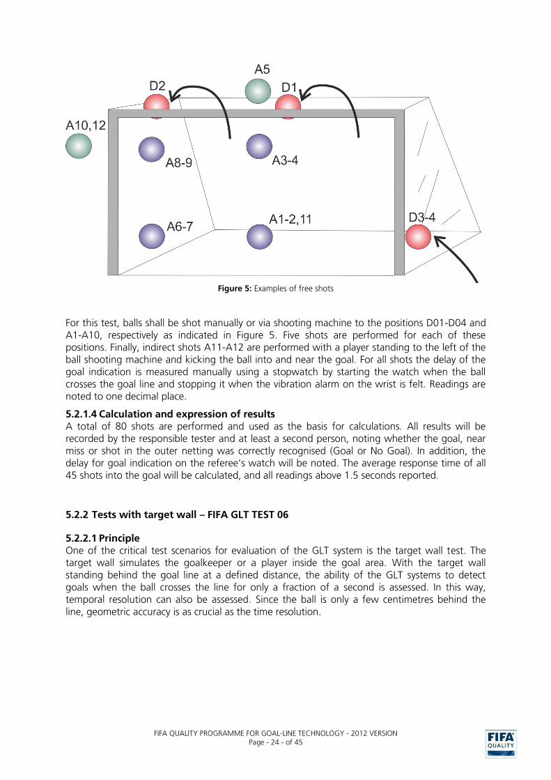
Figure 5: Examples of free shots
For this test, balls shall be shot manually or via shooting machine to the positions D01-D04 and A1-A10, respectively as indicated in Figure 5. Five shots are performed for each of these positions. Finally, indirect shots A11-A12 are performed with a player standing to the left of the ball shooting machine and kicking the ball into and near the goal. For all shots the delay of the goal indication is measured manually using a stopwatch by starting the watch when the ball crosses the goal line and stopping it when the vibration alarm on the wrist is felt. Readings are noted to one decimal place.
5.2.1.4 Calculation and expression of results A total of 80 shots are performed and used as the basis for calculations. All results will be recorded by the responsible tester and at least a second person, noting whether the goal, near miss or shot in the outer netting was correctly recognised (Goal or No Goal). In addition, the delay for goal indication on the referee’s watch will be noted. The average response time of all 45 shots into the goal will be calculated, and all readings above 1.5 seconds reported.
5.2.2 Tests with target wall – FIFA GLT TEST 06
5.2.2.1 Principle One of the critical test scenarios for evaluation of the GLT system is the target wall test. The target wall simulates the goalkeeper or a player inside the goal area. With the target wall standing behind the goal line at a defined distance, the ability of the GLT systems to detect goals when the ball crosses the line for only a fraction of a second is assessed. In this way, temporal resolution can also be assessed. Since the ball is only a few centimetres behind the line, geometric accuracy is as crucial as the time resolution.

FIFA QUALITY PROGRAMME FOR GOAL-LINE TECHNOLOGY - 2012 VERSION
Page - 25 - of 45
Figure 6: Scenario 2: Shots on the target wall
5.2.2.2 Apparatus The target wall should be built entirely of non-metallic materials with the exception of a few short screws. The wall is positioned manually to prevent damage to the pitch and is loaded with dead weight (e.g. water tanks) to avoid a relocation of the position from shot to shot. It has roughly the shape of a player.
Figure 7: Target wall used during first GLT tests
Technical data
Dimensions: Target wall: 80 x 192cm / Base plate: 80 x 120cm Material: Wooden plates, plastic screws for levelling
Positioning: Front edge aligned parallel to goal line (line remains fully visible) Fixation: Dead weight (e.g. water tanks, distributor and order number) Weight: The total weight (including dead weight) is at least 220kg
See also technical data above and CAD drawings for detailed technical information (Appendix A).
The dummy players to be used for the tests with restricted view are to be made entirely from non-metallic materials to prevent disturbance of systems measuring electromagnetic fields and have the size and shape of an average football player (minimum dimensions, height: 165cm, width: 50cm, shoulder height 140cm) wearing a football kit consisting of two different colours.
160cm

FIFA QUALITY PROGRAMME FOR GOAL-LINE TECHNOLOGY - 2012 VERSION
Page - 26 - of 45
A high-speed camera with a minimum of 2000 fps and 1000x1200 pixel resolution is to be used for part of the tests. Because of the short exposure time, intense lighting could be needed, especially under floodlight conditions. Therefore, for some of the tests, a flicker-free lamp can be used.
5.2.2.3 Procedure
5.2.2.3.1 Tests with unrestricted view The front part of the target wall is aligned parallel to the goal line and orthogonal to the pitch inside the goal. In order not to disturb camera-based systems, the goal line has to be fully visible at all times.
The shots B01 – B10 are conducted for this test (see B4.1.2.2). Since the ball is deformed when hitting the wall, it is also possible to verify if the system correctly accounts for this effect. A high-speed camera is used for part of these tests in order to verify the goal event in function of the distance of the target wall. This is done by detailed analysis of the slow and fast shots (different ball speeds will result in different deformation intensities and slightly different trigger points of goal situations).
During the tests, the camera is positioned close to the right post of the goal, and the centre of the image is carefully aligned with the goal line using two reference plumb lines, which are positioned next to each side of the target wall.
When a free view of the high-frequency camera behind the goal posts is not possible, the camera can be positioned inside the goal. A wooden shield to prevent balls bouncing back from the target wall to hit the camera can be installed. If the flicker-free lamp is necessary it is positioned inside the goal area to illuminate the ball during the impact on the wall.
Figure 8: a) No goal and b) goal images captured at 2000 fps (EMPA 208785_Fifa-GLT2-Report). The red line schematically shows the goal line.
Figure 8 a) shows the ball at its maximum deformation during a no-goal shot (wall at 125mm, ball speed of 35km/h) and a goal shot (250mm, 35km/h). A line can be added digitally to serve as a visual indication of the goal line on the level of the impact wall.

FIFA QUALITY PROGRAMME FOR GOAL-LINE TECHNOLOGY - 2012 VERSION
Page - 27 - of 45
The ball is shot onto the target wall using the ball shooting machine as set up in FIFA GLT TEST 05.
A total of 42 shots are performed and used as the basis for calculations. At least 10 shots must
be clear goal situations (≥240mm distance to the goal line). For those shots the delay of the goal indication is measured manually using a stopwatch by starting the watch when the ball hits the wall and stopping it when the vibration alarm on the wrist is felt. Readings are noted to one decimal place.
5.2.2.3.2 Tests with restricted view For this test, two dummy players are positioned on each side (total of 4 dummy players) to partially block the view before the ball hits the target wall. This scenario is selected to simulate the situation when players and/or the goalkeeper prevent a direct view of the ball. Camera-based systems will have to make sure that, by using multiple cameras and/or optimised positioning and viewing angle of the cameras, the ball will be always visible.
Figure 9: Positioning of four dummies
This set-up applies to the target wall. Two dummies are each centred at a right angle to the goal line at a distance of 80cm apart. A second series is in line with the first row with a free distance of 30cm. The target wall will be located in the middle between the dummies.
For this test, 5 shots of each scenario C01 and C02 (see B4.1.2.2) are performed and used as the basis for calculation.
5.2.2.3.3 Tests with indirect shots and restricted view In order to have as realistic a simulation as possible, a set of indirect shots (shot by the ball shooting machine and deflected on to the target wall by a tester acting as a player) are performed with the dummies acting as obstacles. For this test, 4 dummies are used.
For this test, 5 shots of each test scenario C03 and C04 (see B4.2.1.2) are performed and used as the basis for calculation.

FIFA QUALITY PROGRAMME FOR GOAL-LINE TECHNOLOGY - 2012 VERSION
Page - 28 - of 45
5.2.3 Slider test – FIFA GLT TEST 07
5.2.3.1 Principle In order to determine the exact point at which the GLT system triggers and indicates the goal, the slider test device is placed on the goal line and the ball is slowly and progressively moved across the line. A precise measurement of the location of the ball when the system is triggered is possible in this test.
5.2.3.2 Apparatus A slide or translation stage is used to move the ball slowly (approx. 1cm/s) across the goal line in order to determine the exact trigger point for goal detection.
Figure 10: Slide or translation stage to assess the trigger point for goal detection
Technical data
Dimensions: Base plate wall: 90 x 40cm
Material: Wooden plates, plastic screws for levelling Positioning: Short end in parallel to the goal line, crank outside of the goal Fixation: No additional fixation
See also technical data above and CAD drawings for detailed technical information (Appendix B).
5.2.3.3 Procedure The frame of the slide is positioned over the goal line at 0.8m from the left post and aligned to it (see Figure 11). With the ball on the bars, the position of the goal event is assessed using a plumb line (orthogonal to the pitch and the inner edge of the goal line). To start the measurement, the ball is taken from a position where it is clearly outside the goal and placed on the outer end of the slider. The operator is working from the goal mouth and moves the ball continuously such that it rolls across the goal line until the GLT system indicates a goal. The position of its back end with respect to the previously found zero position of the goal line is recorded and allows the offset where a goal is triggered to be determined. The test is repeated with the slide positioned in the centre of the goal at 3.6m.
A total of 10 goal events in two different positions E01 and E02 are performed and used as the basis for calculations (see B4.1.2.4).

FIFA QUALITY PROGRAMME FOR GOAL-LINE TECHNOLOGY - 2012 VERSION
Page - 29 - of 45
Figure 11: Position of slide on the goal line
5.2.4 Tests of functionality of referee’s watch – FIFA GLT TEST 08
5.2.4.1 Principle In order to ensure that the referee would get the indication of a goal anywhere on the pitch and within the required time of one second, the watch is tested for these parameters.
5.2.4.2 Apparatus No apparatus other than six referee’s watches and an interfering transmitter (see B5.2.7.2) is needed for this test.
5.2.4.3 Procedure The functioning of the referee’s indication device is tested according to the following specifications.
5.2.4.3.1 Time of goal indication To measure the delay between the ball crossing the line and the watch indicating a goal, several shots are performed for which the goal event and goal indication time are compared. The procedure is described in B5.2.1.3 and B5.2.2.3.1. The numbers of shots is defined in section B4.1.2.4 and B4.2.1.4.
5.2.4.3.2 Indication to referee only To ensure that only the referee receives the indication through visual confirmation on the watch and vibration, it must be assessed that no other form of confirmation is emitted.
5.2.4.3.3 Range check; full coverage of goal indication on referee’s watch Goal indication has to work in all the positions on the field a referee or assistant referee might be in during a match (see B4.1.2.4). Two members of the test team position themselves at the corner points of the goal with two referee watches each; a third member is on the penalty point with one watch; the person responsible for the remains in the goal area with the ball, one watch and an interfering transmitter. The person responsible for the test throws the ball into the goal and all watch indications are recorded by all testers. Then, the testers at the corners and the penalty point move to the centre line (see Figure 12). The person responsible for the test throws the ball into the goal again and all watch indications are recorded by all testers. Then the testers move to the opposite goal and corner and the procedure is repeated. On the way back, the procedure is repeated in at least two positions, including the area which is at least five (5) meters outside the perimeter of the pitch, but the interfering transmitter is activated by the person responsible for the test while the ball is thrown into the goal.

FIFA QUALITY PROGRAMME FOR GOAL-LINE TECHNOLOGY - 2012 VERSION
Page - 30 - of 45
Position 1 Position 2 Position 3
Figure 12: Full coverage of goal indication on referee’s watch
5.2.5 Additional randomised shots – FIFA GLT TEST 09
5.2.5.1 Principle In addition to the standardised tests, each GLT system will be tested with a series of shots into the goal that the testers carry out at random during the pre-defined testing blocks to check whether the GLT system is continuously operative.
5.2.5.2 Apparatus No particular test apparatus is required for this test.
5.2.5.3 Procedure During the testing blocks (see B4.1.2.5 and B4.2.1.5), the tester shoots the ball into the net from random positions, at random speed. For all tests, note is taken of whether a goal was indicated.
5.2.6 Goalkeeper test – FIFA GLT TEST 10 5.2.6.1 Principle Shots on a goalkeeper are used to simulate real situations. The situations include catching the ball with both hands in front of the body as well as catching the ball and embracing it with both arms. The latter version covers a considerable part of the ball, increasing the chance that ball tracking will be lost by camera-based systems. In the third situation, the ball rolls into the goal beneath the goalkeeper.
5.2.6.2 Apparatus For the goalkeeper test, a human tester dressed in goalkeeping gear (shirt and gloves) is used. While size and weight are not critical, they should ideally be representative of a goalkeeper.

FIFA QUALITY PROGRAMME FOR GOAL-LINE TECHNOLOGY - 2012 VERSION
Page - 31 - of 45
5.2.6.3 Procedure A) The goalkeeper positions himself approximately 1m in front of the goal line. The ball is delivered at moderate speed either by the ball shooting machine or a player. The goalkeeper catches the ball with both hands on the side of the ball in front of the body (see Figure 13). Holding the ball, the goalkeeper slowly walks backwards over the goal line (approx. 0.5 m/s) until the ball is at least 20cm behind the goal line, then returns to the field. This scenario F01 is repeated five times.
B) The goalkeeper positions himself approximately 1m in front of the goal line. The ball is delivered at moderate speed either by the ball shooting machine or a player. The goalkeeper catches the ball and embraces it with both arms and forearms parallel (see Figure 14). Holding the ball, the goalkeeper slowly walks backwards over the goal line (approx. 0.5 m/s) until the ball is at least 20 cm behind the goal line, then returns to the field. This scenario F02 is repeated five times.
C) The goalkeeper positions himself with his feet on the goal line. He crouches down and forms a tunnel with his arms and legs, fingertips touching the ground. The ball is placed 1m in front of the goalkeeper, and a player hits it gently so that it rolls through the tunnel into the goal (see Figure 15). This scenario F03 is repeated five times. In the fourth and fifth repetition one player moves into the goal and kicks the ball out.
For all tests (see B4.2.1.6), note is taken of whether a goal was indicated. If so, it must be verified that the whole ball circumference was over the line at the time of goal indication and the delay of indication must be estimated.
Figure 13: A) Catching the ball with the hands in front of the body

FIFA QUALITY PROGRAMME FOR GOAL-LINE TECHNOLOGY - 2012 VERSION
Page - 32 - of 45
Figure 14: B) Catching the ball with arms and embracing it
Figure 15: C) Crouching position, ball rolls into goal
Evaluation:
A total of 25 shots are performed during the goalkeeper test. A minimum of 5 shots are performed for each of the versions. The additional ten shots for the tests F04 and F05 are left to the discretion of the tester based on which tests look most challenging for the system. Note on the protocol sheet whether a goal was indicated, verify if the whole circumference was over the line at the time of goal indication and also check delay of indication.
5.2.7 Test of immunity to adverse conditions – FIFA GLT Test 11
5.2.7.1 Principle Several tests are performed to assess the immunity of a GLT system to adverse conditions. Simulated situations on the field and its environment include the presence of objects and materials that players or fans might bring or throw on, sudden climatic changes, wear-out of the ball, or faulty electrical installations. Specific equipment is used for these tests. Some of the tests may influence all potential GLT systems, whereas others are designed to test specific classes of systems (such as camera-based systems or systems using electromagnetic fields).
FIFA QUALITY PROGRAMME FOR GOAL-LINE TECHNOLOGY - 2012 VERSION
Page - 33 - of 45
5.2.7.2 Apparatus These tests require a set of specialised material and equipment which may depend on the GLT system.
For all GLT systems the following materials are required: o Bright objects (e.g. white toilet paper rolls) o Metallic objects (e.g. metallic water bottle, min. 0.33l; metallic wrench, min. 0.3kg) o Two sheets of white linen (min. 1.2m wide and 7m long; min. 1.2m wide and 10m long) o Smoke machine based on glycol/water fluid with a hose of at least 5m in length o Mobile phone o Wireless garage opener or other activating device as interfering transmitter (ISM
frequency band around 863-870 MHz, rated operating distance at least 100m (free field))
For camera-based systems, the following are also required:
o Flashlights (professional camera flashlight or high-speed camera illumination strobe) o Laser pointers (two green laser pointers, wavelength around 532nm, min. 5mW power) o Balls with additional or worn out labels/marks (three places, dark colour, at least 0.5 x
2cm2 each)
For magnetic field-based systems, the following are also required
o Single wire power lines (length at least 10m) with two junctions to separate and recombine phase and neutral conductor of the power cord
o Electric device capable of burst discharges or generating electromagnetic fields by switching on a load of at least 500W
For RFID-based systems, the following are also required
o Radio frequency source, adapted to the frequency band used by the GLT system (e.g. Bluetooth sender in the 2450 MHz band)
5.2.7.3 Procedure A set of tests G01-G09 will be performed under adverse conditions.
1) Presence of bright objects (G01): Place the metallic water bottle inside the goal halfway between the goal line and the corner of the net. Throw two toilet paper rolls from the back on top of the goal (centre and left side), allowing it to unroll; place a third toilet paper roll next to the goal (right side), one metre from the base line and touching the net. Perform five free shots with low speed according to the protocol for unrestricted shots.
2) Snow simulation test (G02): Unroll the short linen inside the goal parallel to the goal line; unroll the long linen outside the goal parallel to the goal line. Leave a minimum of 15cm space to the goal line. Wet the ball. Perform five free shots with low speed according to the protocol for unrestricted shots.
3) Dirty ball test (G03): Perform five free shots with low speed according to the respective protocol using the ball with additional marks which should simulate a dirty ball.
4) a) Laser pointer test (G04): (camera-based systems only) The regulations and instructions for laser safety have to be followed (see A4). Target two GLT cameras on the same side of the stadium with the two lasers. Activate lasers during the shots. Perform five free shots with low speed according to the protocol for unrestricted shots.

FIFA QUALITY PROGRAMME FOR GOAL-LINE TECHNOLOGY - 2012 VERSION
Page - 34 - of 45
b) Field distortion test (G04): (magnetic field-based GLT systems only) Mount the metallic wrench on a cord and let it hang from the goal bar, 2m from the left post. Length of the cord is at least 1m. Let the wrench swing during the shots. Perform five free shots with low speed according to the protocol for unrestricted shots.
5) Flashlight test (G05): Activate the flashlight (at least three strokes within two seconds) or strobe the illumination during the shots. Perform five free shots with low speed according to the protocol for unrestricted shots.
6) Smoke test (G06): Use the smoke generator to simulate the presence of fog or use of a smoke petard. Place the generator upwind and use the hose to create fog on top of the goal area. Wait until the goal is sufficiently visible (that a match would be possible) and perform five free shots with low speed according to the protocol for unrestricted shots.
7) Interfering transmitter test (G07): Activate the mobile phone, wireless garage opener or other activating device near the referee watches and note any goal indication of the watches. Repeat for all transmitter channels (buttons). Then, activate the devices during the shots. Perform five free shots with low speed according to the protocol for unrestricted shots.
8) Second ball interference (G08): Place a second ball outside the goal, 1m behind the goal line, 1m from the net. Perform five free shots with low speed according to the protocol for unrestricted shots. Remove and reposition the second ball before each shot.
9) Line test (G09): The single wire power line (phase conductor) is placed behind the goal next to the net with the electric device (load) on one side and power connection on the other side (see Figure 16). The neutral conductor is laid at a distance of at least 2m parallel to the power line. The electric device is activated or switched on during the shots. Perform five shots with low speed according to the protocol for unrestricted shots.
Figure 16: Line test, schematic. “Power“ and “Load“ are the splitters to separate the neutral conductor from the phase.
A total of 45 shots are performed for all GLT systems to assess immunity to adverse conditions. Five shots per type of inference are to be used for calculation of results.
Neutral
Power
Load
Phase

FIFA QUALITY PROGRAMME FOR GOAL-LINE TECHNOLOGY - 2012 VERSION
Page - 35 - of 45
5.2.8 Training session – FIFA GLT TEST 12
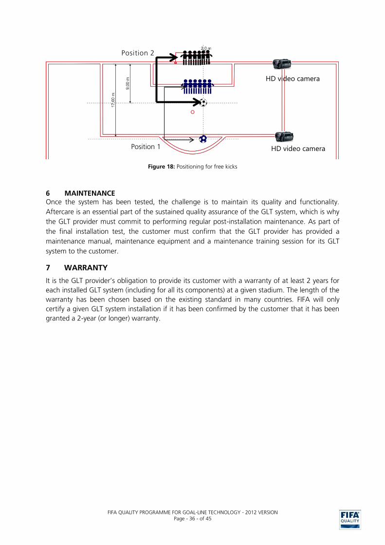
5.2.8.1 Principle To simulate goal situations with some degree of unpredictability, a training session will be arranged by a local football club. A total of four scenarios are played on both goals. Corner balls (left/right) and free kicks (9m/17m) into the penalty area are performed by at least 14 players in two different shirts corresponding to two teams. This test setting simulates standard situations of a real game and implies many goal situations, some of which might be critical. The training sessions must be recorded with HD video cameras to have proof of goal events which were related to the goal indication from the referee’s watch.
5.2.8.2 Apparatus Fourteen players from a local football club dressed in distinctive shirts (7 v. 7) will be needed for this test.
5.2.8.3 Procedure The players simulate set pieces (see B4.1.3). The order and frequency of the events are clearly dictated by the testing team. Should one set piece not lead to a goal situation it should be repeated so as to have sufficient data.
40 shots are performed for this test. At least the following situations and number of repetitions will be applied for both goals:
- 2 x 5 corner situations (H01, H02, H05, H06) per side (see Figure 17)
- 2 x 5 free kicks from two different distances (H03, H04, H07, H08) per side (see Figure 18)
Figure 17: Positioning for corner kicks
HD video camera
HD video camera
FIFA QUALITY PROGRAMME FOR GOAL-LINE TECHNOLOGY - 2012 VERSION
Page - 36 - of 45
Figure 18: Positioning for free kicks
6 MAINTENANCE Once the system has been tested, the challenge is to maintain its quality and functionality.
Aftercare is an essential part of the sustained quality assurance of the GLT system, which is why
the GLT provider must commit to performing regular post-installation maintenance. As part of
the final installation test, the customer must confirm that the GLT provider has provided a
maintenance manual, maintenance equipment and a maintenance training session for its GLT
system to the customer.
7 WARRANTY
It is the GLT provider’s obligation to provide its customer with a warranty of at least 2 years for
each installed GLT system (including for all its components) at a given stadium. The length of the
warranty has been chosen based on the existing standard in many countries. FIFA will only
certify a given GLT system installation if it has been confirmed by the customer that it has been
granted a 2-year (or longer) warranty.
Position 2
HD video camera
HD video camera Position 1

FIFA QUALITY PROGRAMME FOR GOAL-LINE TECHNOLOGY - 2012 VERSION
Page - 37 - of 45
C CHECK BY THE REFEREE
The IFAB has clarified the referee’s position in the Laws of the Game (Law 5) by stating that match officials can use the GLT system as a support provided they are convinced of its functionality, for which appropriate tests shall be carried out before the match.
1 TESTS BEFORE THE MATCH
The match officials are obliged to check the functionality of the GLT system by means of specific tests before it is used prior to each match. If the tests do not satisfy the referee, he can reject the use of the GLT system and therefore decide not to use it for the relevant match. One hour before kick-off, the stadium operator, club, competition organiser (as appropriate) or GLT provider has to hand over the match balls and 6 referees’ watches to the match officials for the final check and the decision on the use of the installed GLT system.
In addition, FIFA recommends that a first check of the GLT system by the referee should be carried out as soon as the match officials have arrived at the stadium in order to give the stadium operator, club, competition organiser (as appropriate) or the provider of the GLT system the opportunity to make final adjustments to the GLT system.
Once the decision has been taken as to whether the GLT system will be used or not in a match, the stadium operator must be immediately informed. Furthermore, after the final whistle, the match officials are obliged to inform the organiser of the competition if the GLT system was used during the match and functioned properly or whether the use of the GLT system was rejected by the referee.
BEFORE KICK-OFF ACTION RESPONSIBLE OPTION
-90minutes First check by the referee after arrival at the stadium
Referee Optional
-90 to -60minutes Adjustments to the GLT system can be made
Provider of the GLT system Optional
-60minutes Final check and decision by the match officials
Referee Compulsory
-45minutes Information on the final decision given to the stadium operator
Referee Compulsory
-45 minutes to kick-off
No further adjustments of the GLT system are allowed
Provider of the GLT system Compulsory
After final whistle
Information to be given to the organiser of the competition on the functionality of the GLT system
Referee Compulsory
Table 24: Time schedule before kick-off
1.1 Description of referee check Subject to the confirmation by the GLT provider that the GLT system is ready to use, the match officials must verify that the GLT system is working on both goals and confirm that they will use it for the match.
Depending on the technology employed for the GLT system, the check by the referee has to be carried out with only one or all footballs to be used in the match. This information is to be provided to the match officials at the latest on their arrival in the stadium by the GLT provider or stadium operator.

FIFA QUALITY PROGRAMME FOR GOAL-LINE TECHNOLOGY - 2012 VERSION
Page - 38 - of 45
1.1.1 GLT system without ball modification
When the football has not been modified (no technology inside the ball), it is sufficient for the test to be carried out with one ball. No other ball may be visible on the pitch. If weather conditions are bad, the ball intended for these weather conditions also has to be used in the check by the referee. An international match ball can be identified by the FIFA QUALITY APPROVED/INSPECTED or IMS mark.
1.1.2 GLT system with ball modification
For GLT systems with modifications to the ball (technology inside the ball), it is essential that the test is carried out with all balls to be used in the match (this test needs only be carried out with all the balls in one goal; in the other goal, the test can be carried out with one of the balls). No other ball, except the one which is used by the referee for the check, may be visible on the pitch during the checks. If weather conditions are bad, all balls intended for these weather conditions must also be checked by the referee. These balls are marked with one of the FIFA quality seals and the GLT word mark.
1.1.3 Test procedures
Three simple tests are applied by the match officials to verify the functionality of the installed GLT system. All referees’ watches and the appropriate balls for the GLT system (see C1.1.1, C1.1.2) have to be used for the following checks.
1.1.3.1 Test 1
a) Procedure
The ball (either one ball as per section C1.1.1 or all balls as per section C.1.1.2) is to be carried once over the goal line outside the goal.
b) Requirement
No “GOAL” indication on any referees’ watches at any time.
Figure 19: Test 1
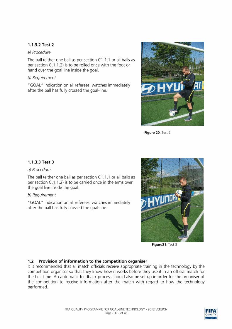
FIFA QUALITY PROGRAMME FOR GOAL-LINE TECHNOLOGY - 2012 VERSION
Page - 39 - of 45
1.1.3.2 Test 2
a) Procedure
The ball (either one ball as per section C1.1.1 or all balls as per section C.1.1.2) is to be rolled once with the foot or hand over the goal line inside the goal.
b) Requirement
“GOAL” indication on all referees’ watches immediately after the ball has fully crossed the goal-line.
Figure 20: Test 2
1.1.3.3 Test 3
a) Procedure
The ball (either one ball as per section C1.1.1 or all balls as per section C.1.1.2) is to be carried once in the arms over the goal line inside the goal.
b) Requirement
“GOAL” indication on all referees’ watches immediately after the ball has fully crossed the goal-line.
Figure21: Test 3
1.2 Provision of information to the competition organiser It is recommended that all match officials receive appropriate training in the technology by the competition organiser so that they know how it works before they use it in an official match for the first time. An automatic feedback process should also be set up in order for the organiser of the competition to receive information after the match with regard to how the technology performed.
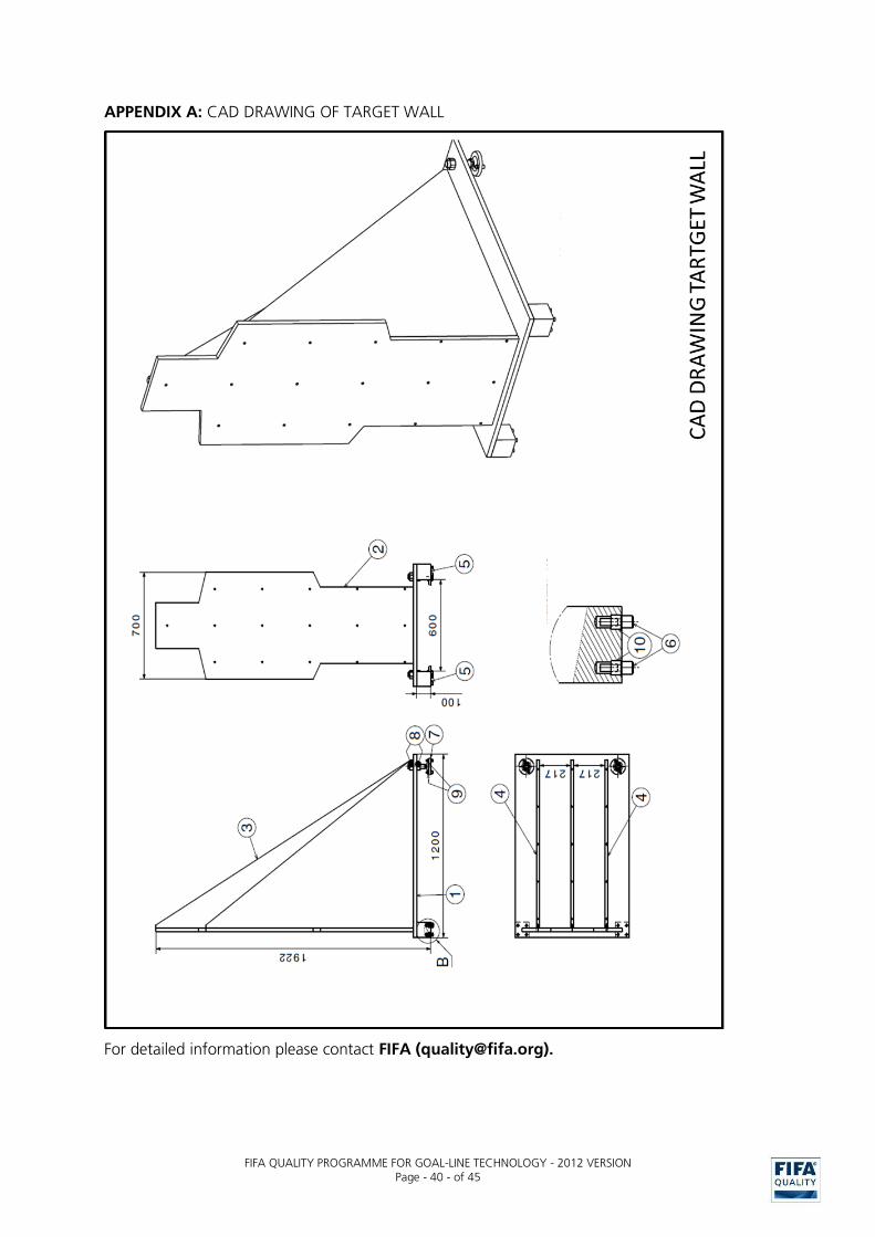
FIFA QUALITY PROGRAMME FOR GOAL-LINE TECHNOLOGY - 2012 VERSION
Page - 40 - of 45
APPENDIX A: CAD DRAWING OF TARGET WALL
For detailed information please contact FIFA ([email protected]).

FIFA QUALITY PROGRAMME FOR GOAL-LINE TECHNOLOGY - 2012 VERSION
Page - 41 - of 45
APPENDIX B: CAD DRAWING OF SLIDER
For detailed information please contact FIFA ([email protected]).

FIFA QUALITY PROGRAMME FOR GOAL-LINE TECHNOLOGY - 2012 VERSION
Page - 42 - of 45
APPENDIX C: GLT SYSTEM TEST PROTOCOL
GLT system test (stadium 1, field test)
System Date Signature test institute
GLT SYSTEM TEST (Stadium 1, field test) Random
1 2 3 4 5
A Unrestricted shots KM/H SHOTS TIME FPS
A01 Centre, flat 35 5 5 25 / / / / /
A02 Centre, flat 70 5 5 25 / / / / /
A03 Centre, high 35 5 5 25 / / / / /
A04 Centre, high 70 5 5 25 / / / / /
A05 Centre, over the goal 70 5 5 25 / / / / /
A06 Left, flat 35 5 5 25 / / / / /
A07 Left, flat 70 5 5 25 / / / / /
A08 Left, high 35 5 5 25 / / / / /
A09 Left, high 70 5 5 25 / / / / /
A10 Left, beside the goal 70 5 5 25 / / / / /
A11 Into the goal – indirect by player - 5 5 25 / / / / /
A12 Near misses – indirect by player - 5 5 25 / / / / /
D Unrestricted shots into the outer netting KM/H SHOTS TIME FPS G=Goal, N=NoGoal / Delay in Seconds
D01 Centre, top manually 5 5 25 / / / / / /
D02 Left, top manually 5 5 25 / / / / / /
D03 Side manually slow 5 5 25 / / / / / /
D04 Side manually fast 5 5 25 / / / / / /
B Target wall (with High Speed Video) KM/H POSITION SHOTS TIME FPS G=Goal, N=NoGoal / Delay in Seconds
B01 50 120 3 9 2000 / / / /
B02 50 160 3 9 2000 / / / /
B03 50 200 3 9 2000 / / / /
B04 50 240 3 9 2000 / / / /
B05 50 180 5 15 2000 / / / / / /
B06 50 190 5 15 2000 / / / / / /
B07 50 185 5 15 2000 / / / / / /
B Target wall (without High Speed Video) KM/H POSITION SHOTS TIME FPS G=Goal, N=NoGoal / Delay in Seconds
B08 Positions see B05-B07 50 180 5 5 25 / / / / / /
B09 Positions see B05-B07 50 190 5 5 25 / / / / / /
B10 Positions see B05-B07 50 185 5 5 25 / / / / / /
C Target wall (restricted view) KM/H POSITION SHOTS TIME FPS G=Goal, N=NoGoal / Delay in Seconds
C01 35 125 5 7.5 25 / / / / / /
C02 70 250 5 7.5 25 / / / / / /
E Slider test SHOTS TIME FPS Zero position (Goal) Trigger position
E01 Left 5 10 25 /
E02 Center 5 10 25 /
U Coverage of referee's watch SHOTS TIME FPS Visuell, Vibration and <1s on all 6 watches
U01 Corner, centre, sidelines… 5 10 25 / / / / /
U02 as U01 but with senders 5 10 25 / / / / /
G Immunity to adverse conditions KM/H SHOTS TIME FPS G=Goal, N=NoGoal / Delay in Seconds
G01 bright objects 35 5 10 25 / / / / /
G02 snow simulation 35 5 10 25 / / / / /
G03 dirty ball 35 5 10 25 / / / / /
G04 laserpointer/field distortion 35 5 10 25 / / / / /
G05 flash light 35 5 10 25 / / / / /
G06 smoke test 35 5 10 25 / / / / /
G07 jamming transmitter 35 5 10 25 / / / / /
G08 2nd ball 35 5 10 25 / / / / /
G09 line test 35 5 10 25 / / / / /
H Training session SHOTS TIME FPS G=Goal, N=NoGoal
H01 Goal 1, Corner right 5 10 25
H02 Goal 1, Corner left 5 10 25
H03 Goal 1, Free kick, Pos 1 5 10 25
H04 Goal 1, Free kick, Pos 2 5 10 25
Break, changing side 10
H05 Goal 2, Corner right 5 10 25
H06 Goal 2, Corner left 5 10 25
H07 Goal 2, Free kick, Pos 1 5 10 25
H08 Goal 2, Free kick, Pos 2 5 10 25
A Unrestricted shots KM/H SHOTS TIME FPS G=Goal, N=NoGoal / Delay in Seconds
A01 Centre, flat 35 5 5 25 / / / / /
A02 Centre, flat 70 5 5 25 / / / / /
A03 Centre, high 35 5 5 25 / / / / /
A04 Centre, high 70 5 5 25 / / / / /
A05 Centre, over the goal 70 5 5 25 / / / / /
A06 Left, flat 35 5 5 25 / / / / /
A07 Left, flat 70 5 5 25 / / / / /
A08 Left, high 35 5 5 25 / / / / /
A09 Left, high 70 5 5 25 / / / / /
A10 Left, beside the goal 70 5 5 25 / / / / /
A11 Into the goal – indirect by player 5 5 25 / / / / /
A12 Near misses – indirect by player 5 5 25 / / / / /
D Unrestricted shots into the outer net KM/H SHOTS TIME FPS G=Goal, N=NoGoal / Delay in Seconds
D01 Centre, top manually 5 5 25 / / / / / /
D02 Left, top manually 5 5 25 / / / / / /
D03 Side manually slow 5 5 25 / / / / / /
D04 Side manually fast 5 5 25 / / / / / /
B Target wall (with High Speed Video) KM/H POSITION SHOTS TIME FPS G=Goal, N=NoGoal / Delay in Seconds
B01 50 120 3 9 2000 / / / /
B02 50 160 3 9 2000 / / / /
B03 50 200 3 9 2000 / / / /
B04 50 240 3 9 2000 / / / /
B05 50 180 5 15 2000 / / / / / /
B06 50 190 5 15 2000 / / / / / /
B07 50 185 5 15 2000 / / / / / /
B Target wall (without High Speed Video) KM/H POSITION SHOTS TIME FPS G=Goal, N=NoGoal / Delay in Seconds
B08 Positions see B05-B07 50 180 5 5 25 / / / / / /
B09 Positions see B05-B07 50 190 5 5 25 / / / / / /
B10 Positions see B05-B07 50 185 5 5 25 / / / / / /
C Target wall (restricted view) KM/H POSITION SHOTS TIME FPS G=Goal, N=NoGoal / Delay in Seconds
C01 35 125 5 7.5 25 / / / / / /
C02 70 250 5 7.5 25 / / / / / /
E Slider test SHOTS TIME FPS Trigger position
E01 Left 5 10 25 /
E02 Center 5 10 25 /
U Coverage of referee's watch SHOTS TIME FPS Visuell, Vibration and <1s on all 6 watches
U01 Corner, Centre, sidelines… 5 10 25 / / / / /
U02 as U01 but with senders 5 10 25 / / / / /
Split in blocks of 45-60 min.
Goal 1
Goal 2
Results
G=GOAL, N=NO GOAL / DELAY IN SECONDS

FIFA QUALITY PROGRAMME FOR GOAL-LINE TECHNOLOGY - 2012 VERSION
Page - 43 - of 45
GLT system test (stadium 2, field test)
System Date Signature test institute
GLT SYSTEM TEST (Stadium2, field test) Random
1 2 3 4 5
A Unrestricted shots KM/H SHOTS TIME FPS G=Goal, N=NoGoal / Delay in Seconds
A01 Centre, flat 35 5 5 25 / / / / /
A02 Centre, flat 70 5 5 25 / / / / /
A03 Centre, high 35 5 5 25 / / / / /
A04 Centre, high 70 5 5 25 / / / / /
A05 Centre, over the goal 70 5 5 25 / / / / /
A06 Left, flat 35 5 5 25 / / / / /
A07 Left, flat 70 5 5 25 / / / / /
A08 Left, high 35 5 5 25 / / / / /
A09 Left, high 70 5 5 25 / / / / /
A10 Left, beside the goal 70 5 5 25 / / / / /
A11 Into the goal – indirect by player 5 5 25 / / / / /
A12 Near misses – indirect by player 5 5 25 / / / / /
D Unrestricted shots into the outer netting KM/H SHOTS TIME FPS G=Goal, N=NoGoal / Delay in Seconds
D01 Centre, top manually 5 5 25 / / / / / /
D02 Left, top manually 5 5 25 / / / / / /
D03 Side manually slow 5 5 25 / / / / / /
D04 Side manually fast 5 5 25 / / / / / /
B Target wall (with High Speed Video) KM/H POSITION SHOTS TIME FPS G=Goal, N=NoGoal / Delay in Seconds
B01 50 120 3 9 2000 / / / /
B02 50 160 3 9 2000 / / / /
B03 50 200 3 9 2000 / / / /
B04 50 240 3 9 2000 / / / /
B05 50 180 5 15 2000 / / / / / /
B06 50 190 5 15 2000 / / / / / /
B07 50 185 5 15 2000 / / / / / /
B Target wall (without High Speed Video) KM/H POSITION SHOTS TIME FPS G=Goal, N=NoGoal / Delay in Seconds
B08 Positions see B05-B07 50 180 5 5 25 / / / / / /
B09 Positions see B05-B07 50 190 5 5 25 / / / / / /
B10 Positions see B05-B07 50 185 5 5 25 / / / / / /
C Target wall (restricted view) KM/H POSITION SHOTS TIME FPS G=Goal, N=NoGoal / Delay in Seconds
C01 35 125 5 7.5 25 / / / / / /
C02 70 250 5 7.5 25 / / / / / /
E Slider test SHOTS TIME FPS Zero position (Goal) Trigger position
E01 Left 5 10 25 /
E02 Center 5 10 25 /
U Coverage of referee's watch SHOTS TIME FPS Visuell, Vibration and <1s on all 6 watches
U01 Corner, center, sidelines… 5 10 25 / / / / /
U02 as U01 but with senders 5 10 25 / / / / /
Split in blocks of 45-60 min.
Goal 1
Goal 2
Results

FIFA QUALITY PROGRAMME FOR GOAL-LINE TECHNOLOGY - 2012 VERSION
Page - 44 - of 45
APPENDIX D: FINAL INSTALLATION TEST PROTOCOL
Final installation test (field test)
System Date Signature test institute
FINAL INSTALLATION TEST Random
1 2 3 4 5
A Unrestricted shots KM/H SHOTS TIME FPS G=Goal, N=NoGoal / Delay in Seconds
A01 1 Center, flat 35 5 5 25 / / / / /
A02 70 5 5 25 / / / / /
A03 2 Center, high 35 5 5 25 / / / / /
A04 70 5 5 25 / / / / /
A05 3 Center, over 70 5 5 25 / / / / /
A06 4 Left, flat 35 5 5 25 / / / / /
A07 70 5 5 25 / / / / /
A08 5 Left, high 35 5 5 25 / / / / /
A09 70 5 5 25 / / / / /
A10 6 Left, beside 70 5 5 25 / / / / /
A11 Goal Indirect by player 5 5 25 / / / / /
A12 No Goal Indirect by player 5 5 25 / / / / /
D Unrestricted shots into the outer net KM/H SHOTS TIME FPS G=Goal, N=NoGoal / Delay in Seconds
D01 Top, left manually 5 5 25 / / / / / /
D02 Side manually 5 5 25 / / / / / /
D03 Side manually slow 5 5 25 / / / / / /
D04 manually fast 5 5 25 / / / / / /
B Target wall (with High Speed Video) KM/H POSITION SHOTS TIME FPS G=Goal, N=NoGoal / Delay in Seconds
B01 Right 50 120 3 9 2000 / / / /
B02 50 160 3 9 2000 / / / /
B03 50 200 3 9 2000 / / / /
B04 50 240 3 9 2000 / / / /
B05 Depending on the results… 50 180 5 15 2000 / / / / / /
B06 …adjust positions 50 190 5 15 2000 / / / / / /
B07 50 185 5 15 2000 / / / / / /
B Target wall (without High Speed Video) KM/H POSITION SHOTS TIME FPS G=Goal, N=NoGoal / Delay in Seconds
B08 Positions see B05-B07 50 180 5 5 25 / / / / / /
B09 50 190 5 5 25 / / / / / /
B10 50 185 5 5 25 / / / / / /
5
C Target wall (restricted view) KM/H POSITION SHOTS TIME FPS G=Goal, N=NoGoal / Delay in Seconds
C01 Right 35 125 5 7.5 25 / / / / / /
C02 70 250 5 7.5 25 / / / / / /
C03 Indirect by player 125 5 7.5 25 / / / / / /
C04 Indirect by player 250 5 7.5 25 / / / / / /
E Slider test SHOTS TIME FPS Zero position (Goal) Trigger position
E01 Left 5 10 25 /
E02 Center 5 10 25 /
U Coverage of referee's watch SHOTS TIME FPS Visuell, Vibration and <1s on all 6 watches
U01 Corner, Center, Sidelines… 5 10 25 / / / / /
U02 as U01 but with senders 5 10 25 / / / / /
F Goalkeeper test KM/H SHOTS TIME FPS G=Goal, N=NoGoal / Delay in Seconds without Ball
F01 catching in hands 30 5 10 25 / / / / / /
F02 catching in arms 30 5 10 25 / / / / / /
F03 rolling through tunnel Indirect by player 5 10 25 / / / / / /
F04 retest 5 10 25 / / / / / /
F05 retest 5 10 25 / / / / / /
Split in blocks of 45-60 min.
Goal 1
Goal 2
Results

FIFA QUALITY PROGRAMME FOR GOAL-LINE TECHNOLOGY - 2012 VERSION
Page - 45 - of 45
APPENDIX D: FINAL INSTALLATION TEST REPORT