Fiber Optic Locate System 2 (FLS-2) User Handbook UserHandbook VXMT...Fiber Optic Locate System 2...
63
Fiber Optic Locate System 2 (FLS-2) User Handbook (English Edition) Version 1.1 P/N: 4.04.000052
Transcript of Fiber Optic Locate System 2 (FLS-2) User Handbook UserHandbook VXMT...Fiber Optic Locate System 2...
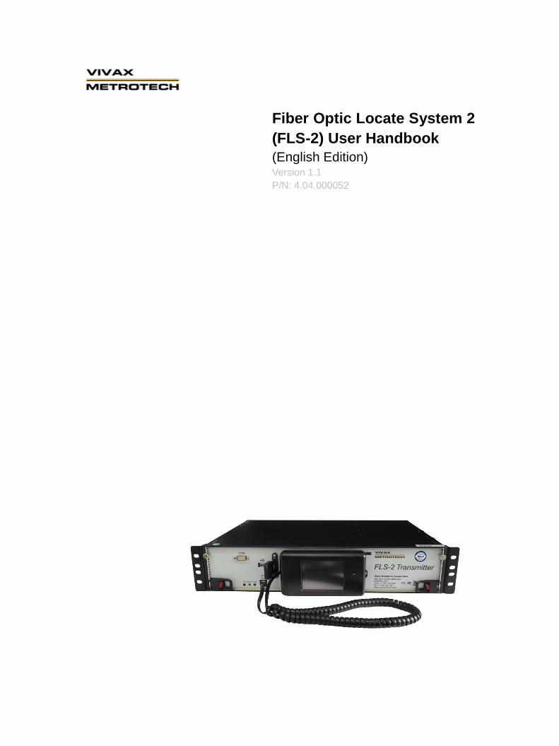
Fiber Optic Locate System 2
(FLS-2) User Handbook
(English Edition) Version 1.1
P/N: 4.04.000052

THE INFORMATION CONTAINED IN THIS DOCUMENT IS FOR INFORMATIONAL PURPOSES ONLY AND IS
SUBJECT TO CHANGE WITHOUT NOTICE. VIVAX-METROTECH CORPORATION MAKES NO WARRANTY OF
ANY KIND WITH REGARD TO THE INFORMATION CONTAINED IN THIS MANUAL, INCLUDING BUT NOT
LIMITED TO THE IMPLIED WARRANTIES OF MERCHANTABILITY AND FITNESS FOR A PARTICULAR PURPOSE.
VIVAX-METROTECH SHALL NOT BE LIABLE FOR ERRORS CONTAINED HEREIN, NOR FOR INCIDENTAL OR
CONSEQUENTIAL DAMAGES FROM THE FURNISHING OF THIS INFORMATION.
THIS MANUAL CONTAINS PROPRIETARY INFORMATION THAT IS PROTECTED BY COPYRIGHT. NO PART OF
THIS MANUAL MAY BE PHOTOCOPIED, REPRODUCED, MAGNETICALLY OR ELECTRONICALLY STORED,
TRANSMITTED, OR TRANSLATED INTO ANOTHER LANGUAGE WITHOUT THE PRIOR WRITTEN CONSENT OF
VIVAX-METROTECH CORPORATION.
THERE ARE NO WARRANTIES, EXPRESSED OR IMPLIED, INCLUDING ANY WARRANTY OF MERCHANTABILITY,
BEYOND THOSE STATED HEREIN.
Vivax-Metrotech warrants its equipment to be free from defects in workmanship and material under normal and proper
use and service for one year from date of purchase by original user, but not to exceed eighteen months after date of
original shipment from the factory. Vivax-Metrotech assumes no obligation to repair or replace equipment that has
been altered or repaired by other than Vivax-Metrotech approved procedure; been subject to misuse, misapplication,
improper maintenance, negligence or accident; had its serial number or any part thereof altered, defaced or removed;
or been used with parts other than those approved by Vivax-Metrotech. Warranty does not include batteries.
Expendable items such as fuses and lamps are excluded.
Any detection product proved defective under this warranty will be repaired or replaced free of charge at the
Vivax-Metrotech Corporation factory or approved Vivax-Metrotech repair station. The equipment should be returned to
our factory by prepaid transportation after requesting and receiving return authorization from our Customer Service
Department. Vivax-Metrotech obligations are limited to repair or replacement of broken or defective parts which have
not been abused, misused, altered or accidentally damaged, or at the option of Vivax-Metrotech, to refund of the
purchase price. Vivax-Metrotech assumes no liability for removal or installation costs, consequential damages, or
contingent expenses of any other nature.
When hooking to live power through an inductive clamp, be certain the clamp connects around the power line, not
directly onto the power line. Please follow your own company’s safety standards, and OSHA requirements.
This product complies with the Class A emission requirements of the FCC Part 15 and standard EN 55011. This
product complies with the EMC requirements of standard EN 61000-6-2.
Metrotech has received ISO 9001:2000 Quality Management System Certification. Metrotech adheres to the quality
standard guidelines of ISO 9001:2000 and ensures quality in its design/development, production, installation, and
servicing disciplines.
FLS-2, vLocPro, MMS, and Signal Select are trademarks of Vivax-Metrotech Corporation. Other trademarks stated in
this document are the property of their respective owners.
© 2014 by Vivax-Metrotech Corporation. All rights are reserved.
Table of Content
1. General Safety .................................................................................................................................. 1
2. Document Conventions .................................................................................................................... 2
3. Introduction ....................................................................................................................................... 4
3.1 System Overview ..................................................................................................................... 4
3.2 Features .................................................................................................................................. 4
3.3 Transmitter Signals .................................................................................................................. 5
3.4 Modular Design ....................................................................................................................... 5
3.5 Specifications .......................................................................................................................... 6
4. Overview ........................................................................................................................................... 9
4.1 Operating Modes ..................................................................................................................... 9
4.2 Method for Controlling the Transmitter .................................................................................... 9
4.3 Hand-Held Display Unit ......................................................................................................... 10
4.4 Overview of the Modules ....................................................................................................... 10
4.4.1 Main Control Module ......................................................................................................... 10
4.4.2 Power Supply Module ....................................................................................................... 10
4.4.3 Rear Module ...................................................................................................................... 10
4.5 LED Status Indicators ............................................................................................................ 11
5. Installing the Transmitter ................................................................................................................. 12
5.1 Installation Site ...................................................................................................................... 12
5.2 Required Tools and Test Equipment ...................................................................................... 12
5.3 Unpacking the Transmitter ..................................................................................................... 12
5.4 Output Connector Pin-Out ..................................................................................................... 13
5.5 Attaching the Rock Mounting Brackets .................................................................................. 13
5.6 Installing or Replacing the Transmitter .................................................................................. 14
5.6.1 Installing the Transmitter ................................................................................................... 14
5.6.2 Replacing a Rack Mounted Transmiteer ........................................................................... 15
5.7 NEBS Specific Installation ..................................................................................................... 15
5.7.1 NEBS Installing the Transmitter with grounding ................................................................ 15
5.7.2 NEBS Requirements ......................................................................................................... 15
5.8 Testing the Transmitter .......................................................................................................... 16
5.9 Telemetry Interface ................................................................................................................ 16
6. Local Transmitter Control ................................................................................................................ 17
6.1 Using the Hand-Held Display Unit ......................................................................................... 17
6.1.1 Main Operating Screen ..................................................................................................... 17
6.1.2 Operating Mode Menu....................................................................................................... 19
6.1.3 Installation Sequence ........................................................................................................ 22
6.1.4 Utilities Menu ..................................................................................................................... 29
6.1.4.1 Edit Menu ................................................................................................................. 30
6.1.4.2 Install Menu .............................................................................................................. 32
6.1.4.3 Save Setup ............................................................................................................... 32
6.1.4.4 Factory Reset ........................................................................................................... 33
6.1.4.5 Software Update ....................................................................................................... 33
6.1.4.6 Calibrate Screen ....................................................................................................... 34
6.1.4.7 About FLS-2-TX ....................................................................................................... 34
6.2 Using the RS-232 Port ........................................................................................................... 35
6.2.1 Configuring Hyper Terminal ............................................................................................... 35
6.2.2 Selecting an Operational Mode ......................................................................................... 36
6.2.3 Programming the Line Setup Featues ............................................................................... 37
6.2.4 Using the Menu ................................................................................................................. 39
6.2.4.1 Locator software ....................................................................................................... 40
6.2.4.2 Factory Reset ........................................................................................................... 40
6.2.4.3 Locator Software (Standby Mode Only) .................................................................... 41
6.2.4.4 Install (Standby Mode Only) ..................................................................................... 42
6.2.4.5 Reinstall (Standby Mode Only) ................................................................................. 43
6.2.4.6 Save Setup ............................................................................................................... 44
6.2.4.7 About FLX-TX ........................................................................................................... 45
7. Remote Transmitter Control ............................................................................................................ 47
FLS-2-TX2W Telephone Remote Control .............................................................................. 48 7.1
FLS-2-TX4W Telephone Remote Control .............................................................................. 49 7.2
FLS-2-TX16W Telephone Remote Control ............................................................................ 50 7.3
8. Alarm Messages ............................................................................................................................. 51
9. Troubleshooting .............................................................................................................................. 52
10. Maintenance ............................................................................................................................... 53
10.1 Calibration ............................................................................................................................. 53
10.2 Removing or Installing Modules............................................................................................. 53
10.3 Cleaning ................................................................................................................................ 53
11. Technical Support ....................................................................................................................... 54
12. Acronyms ................................................................................................................................... 56
13. Glossary ..................................................................................................................................... 57
1 General Safety
Page 1 of 55
1. General Safety
This document contains basic advice for the installation and operation of the Vivax-Metrotech FLS-2
transmitter. Always follow these safety instructions when handling the transmitter and its modules, or when
troubleshooting.
NOTE
The manufacturer is not liable for damage to material or humans due to
non-observance of the instructions and safety advice provided in this document.
Therefore, this document should be provided and reviewed by all personnel
associated with its installation and use.
Intended personnel
Vivax-Metrotech utility line locators are intended for use by utility and contractor
professionals. Safety hazards for underground utility access areas include electrical shock,
explosive gases, and toxic fumes as well as potential influence on communications and
control systems such as traffic control and railroad crossings.
Intended application
Safe operation is only achieved by using the transmitter for its intended purpose. Using the
transmitter for other purposes may lead to human danger and equipment damage. Do not
exceed the limits described in this document.
Output Signal and fiber optic cables
The transmitter output signal is high voltage. When the transmitter sends a signal, the fiber
optic cable sheath and its connections may be energized up to 300V AC TO 450V DC.
Keep a safe distance form these cables and connections.
Lightning strikes
The transmitter must be installed with proper lightning protection. Damage to the
transmitter may occur if it is not properly installed and protected from lightning strikes. We
do not recommend that you operate or perform maintenance on the transmitter if there is a
pending electrical storm near the transmitter or the buried cable.
Modules
Before removing any modules, turn the rear power switch off. The modules were not
designed to be hot-swappable.
Malfunctioning behavior
Use the transmitter only when it is working properly. When irregularities or malfunctions
appear that this document cannot resolve, the transmitter must immediately be put out of
operation and marked as not functional. Contact technical support. Only operate the
transmitter after resolving the malfunction.
Repair and maintenance
Repairs and service must only be done by Vivax-Metrotech Corporation.
2 Document Conventions
Page 2 of 55
2. Document Conventions
This section describes the document text conventions, document icons and symbols and the icons and
symbols that appear on the hand-held display screens.
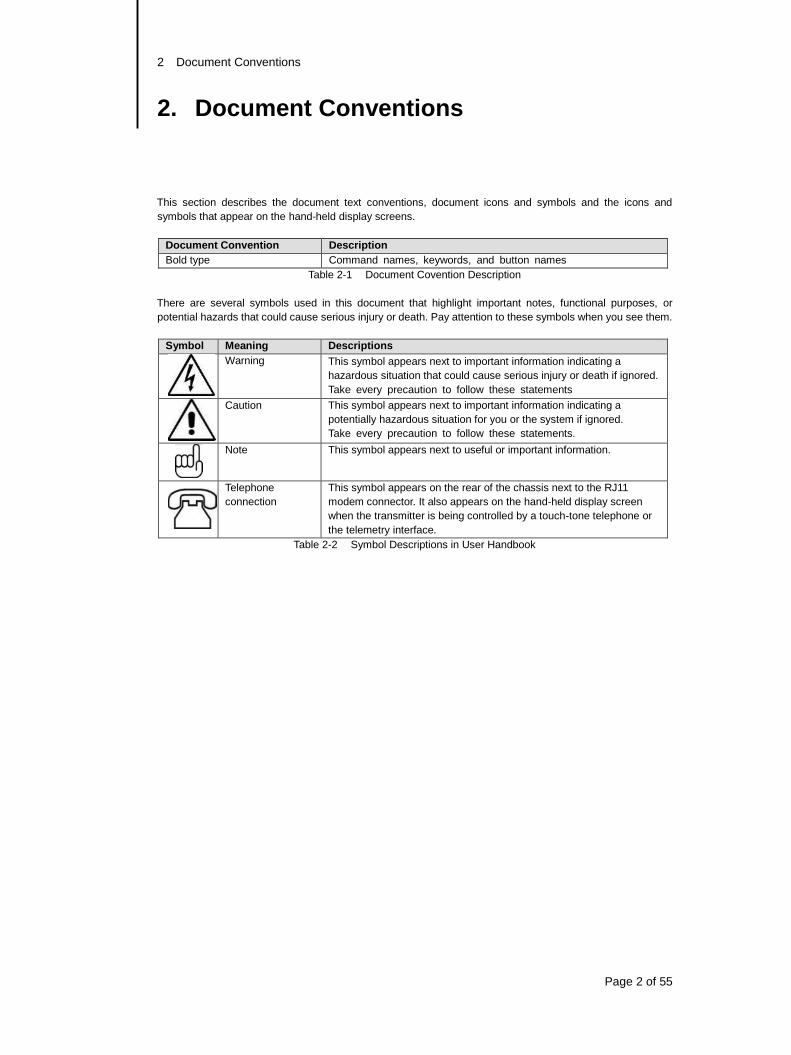
Document Convention Description
Bold type Command names, keywords, and button names
Table 2-1 Document Covention Description
There are several symbols used in this document that highlight important notes, functional purposes, or
potential hazards that could cause serious injury or death. Pay attention to these symbols when you see them.
Symbol Meaning Descriptions
Warning This symbol appears next to important information indicating a
hazardous situation that could cause serious injury or death if ignored.
Take every precaution to follow these statements
Caution This symbol appears next to important information indicating a
potentially hazardous situation for you or the system if ignored.
Take every precaution to follow these statements.
Note This symbol appears next to useful or important information.
Telephone
connection
This symbol appears on the rear of the chassis next to the RJ11
modem connector. It also appears on the hand-held display screen
when the transmitter is being controlled by a touch-tone telephone or
the telemetry interface.
Table 2-2 Symbol Descriptions in User Handbook
2 Document Conventions
Page 3 of 55
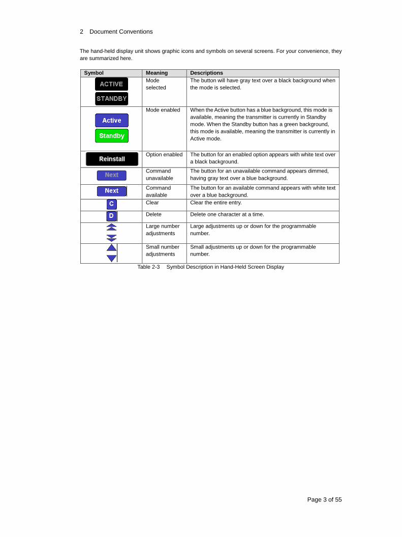
The hand-held display unit shows graphic icons and symbols on several screens. For your convenience, they
are summarized here.
Symbol Meaning Descriptions
Mode
selected
The button will have gray text over a black background when
the mode is selected.
Mode enabled When the Active button has a blue background, this mode is
available, meaning the transmitter is currently in Standby
mode. When the Standby button has a green background,
this mode is available, meaning the transmitter is currently in
Active mode.
Option enabled The button for an enabled option appears with white text over
a black background.
Command
unavailable
The button for an unavailable command appears dimmed,
having gray text over a blue background.
Command
available
The button for an available command appears with white text
over a blue background.
Clear Clear the entire entry.
Delete Delete one character at a time.
Large number
adjustments
Large adjustments up or down for the programmable
number.
Small number
adjustments
Small adjustments up or down for the programmable
number.
Table 2-3 Symbol Description in Hand-Held Screen Display
3 Introduction
Page 4 of 55
3. Introduction
This chapter contains the following sections:
System Overview
Features
Transmitter Signals
Modular Design
Specifications
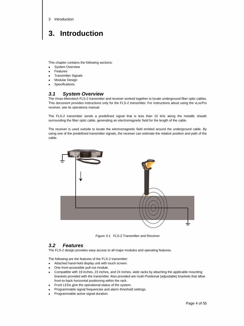
3.1 System Overview The Vivax-Metrotech FLS-2 transmitter and receiver worked together to locate underground fiber optic cables.
This document provides instructions only for the FLS-2 transmitter. For instructions about using the vLocPro
receiver, see its operations manual.
The FLS-2 transmitter sends a predefined signal that is less than 10 kHz along the metallic sheath
surrounding the fiber optic cable, generating an electromagnetic field for the length of the cable.
The receiver is used outside to locate the electromagnetic field emitted around the underground cable. By
using one of the predefined transmitter signals, the receiver can estimate the relative position and path of the
cable.
Figure 3-1 FLS-2 Transmitter and Receiver
3.2 Features The FLS-2 design provides easy access to all major modules and operating features.
The following are the features of the FLS-2 transmitter:
Attached hand-held display unit with touch screen.
One front-accessible pull-out module.
Compatible with 19 inches, 23 inches, and 24 inches, wide racks by attaching the applicable mounting
brackets provided with the transmitter. Also provided are multi-Positional (adjustable) brackets that allow
front-to-back horizontal positioning within the rack.
Front LEDs give the operational status of the system.
Programmable signal frequencies and alarm threshold settings.
Programmable active signal duration.
3 Introduction
Page 5 of 55
Local control access by using the
Attached hand-held display unit.
Front RS-232 connector and a computer.
Rear RJ-45 Ethernet connector, a LAN, and a computer.
Remote control access by using:
Any touch-tone telephone (land line of mobile).
Remote control access via rear RJ-45 Ethernet connector, a LAN, and a computer or a Smart Phone.
Includes an internal modem to connect to the telephone line. This connection allows you to remotely
control the transmitter, download the firmware updates, and monitor the transmitter operation by a
computer.
Includes a telemetry interface for remote control, monitoring, and reporting,
3.3 Transmitter Signals
The transmitter is a signal generator that consists of one or more programmed frequencies that allow you to
locate and trace the fiber optic cable. The predefined frequencies are:
Signal Direction (SD): SD512 (256 Hz and 512 Hz)
Locate Signal (LS): LF512 (512 Hz)
Extremely Low
Frequencies (ELF):
ELF10
Other ELFs available upon request
Note: Other frequencies available
Table 3-1 Predefined Transmitter Frequencies
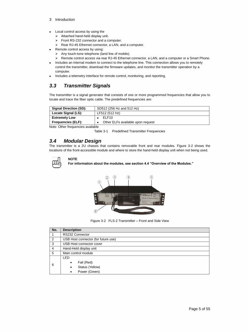
3.4 Modular Design The transmitter is a 2U chassis that contains removable front and rear modules. Figure 3-2 shows the
locations of the front-accessible module and where to store the hand-held display unit when not being used.
NOTE
For information about the modules, see section 4.4 “Overview of the Modules.”
Figure 3-2 FLS-2 Transmitter – Front and Side View
No. Description
1 RS232 Connector
2 USB Host connector (for future use)
3 USB Host connector cover
4 Hand-Held display unit
5 Main control module
6
LED
Fail (Red)
Status (Yellow)
Power (Green)
3 Introduction
Page 6 of 55
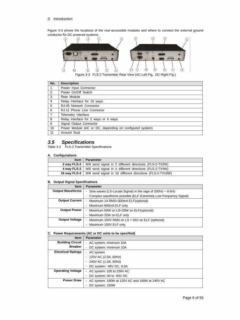
Figure 3-3 shows the locations of the rear-accessible modules and where to connect the external ground
conductor for DC powered systems.
Figure 3-3 FLS-2 Transmitter Rear View (AC-Left Fig., DC-Right Fig.)
No. Description
1 Power Input Connector
2 Power On/Off Switch
3 Rear Module
4 Relay Interface for 16 ways
5 RJ-45 Network Connector
6 RJ-11 Phone Line Connector
7 Telemetry Interface
8 Relay interface for 2 ways or 4 ways
9 Signal Output Connector
10 Power Module (AC or DC, depending on configured system)
11 Ground Stud
3.5 Specifications Table 3-2 FLS-2 Transmitter Specifications
A. Configurations
Item Parameter
2 way FLS-2 Will send signal in 2 different directions (FLS-2-TX2W)
4 way FLS-2 Will send signal in 4 different directions (FLS-2-TX4W)
16 way FLS-2 Will send signal in 16 different directions (FLS-2-TX16W)
B. Output Signal Specifications
Item Parameter
Output Waveforms - Sine waves (LS-Locate Signal) in the rage of 200Hz – 8 kHz
- Complex waveforms possible (ELF-Extremely Low Frequency Signal)
Output Current - Maximum 1A RMS+300mA ELF(optional)
- Maximum 600mA ELF only
Output Power - Maximum 50W on LS+20W on ELF(optional)
- Maximum 32W on ELF only
Output Voltage - Maximum 100V RMS on LS + 65V on ELF (optional)
- Maximum 150V ELF only
C. Power Requirements (AC or DC units to be specified)
Item Parameter
Building Circuit
Breaker
- AC system: minimum 10A
- DC system: minimum 10A
Electrical Ratings - AC system
- 120V AC (2.0A, 60Hz)
- 240V AC (1.0A, 50Hz)
- DC system: -48V DC, 6.0A
Operating Voltage - AC system: 100 to 256V AC
- DC system:-40 to -60V DC
Power Draw - AC system: 180W at 120V AC and 180W at 240V AC
- DC system: 150W
3 Introduction
Page 7 of 55
D. Telemetry Interface
Item Parameter
Alarm Relay Type Isolated
Contact Resistance 10ohm (typical)
Control Relays Accepts From A and C type
Response Time 500ms
E. Environmental Requirements
Item Parameter
Altitude - Operating: 10,000ft (3,048m)
- Non-operating: 40,000ft (12,192m)
Humidity - Operating: 20-55%, non-condensing
Internal Cooling - Fan: Maximum 24.65CFM (0.698CMM) x 2
Temperature - Operating: 320F to 104
0F (0
0C to 40
0C)
- Storage: -40F to 158
0F (-20
0C to 70
0C)
F. Physical
Item Parameter
Weight AC system: 15.8lbs (7.16kg)
DC system: 14.6lbs (6.64kg)
Dimension 19in(W) x 11.85in(D) x 3.46(H) (483mm x 301mm x 88mm)
Hand-held Display
Unit
Touch LCD display screen with attached coiled cable and stylus
Modem, Internal V.92 (56kbps)
RS-232 Port DB9-type connector in front.
Terminal setting:
- 57,600bps
- 8 data bits
- no parity
- 1 stop bit
USB 2.0 USB Type-A socket on front panel
Ethernet 10/100, RJ45 on back panel
G. Rack Mounting Brackets
Item Parameter
Sizes - Standard bracket: 19 in (482.6mm)
- Rack adaptor brackets: 23 in (584.2mm) and 24 in (610mm)
- Multi-position brackets: 19 in (482.6mm), 23in (584.2mm) and 24in
(609.6mm). Allows for maximum 5.25in (133.4mm) front-to-back horizontal
positioning in the rack, using 0.5in (12.7mm) increments.
H. Telephone Access
Item Parameter
Tone Duration Minimum 50ms
Tone Type Standard tones from land line or mobile telephone
I. Ethernet Access
Item Parameter
Ethernet 10Base-T/100Base-TX fast Ethernet.
3 Introduction
Page 8 of 55
J. Approvals
Item Parameter
Approvals - FCC Part15, Class A devices
- EN61000-3-2 (2006)
- EN61000-6-2 (2005)
- EN61000-3-3 (1995)
- EN55011 Group 1, Class A devices
K. Technical Data
Features - Permanently installed 50W transmitter
- Digital signal processing, impedance matching, line monitoring
- Remotely controlled operation
- 2-16 signal direction multiplexing
- ELF output
- Powered by AC or DC
- Data logging of all operating parameters including:
setup changes
alarms
measurements of line conditions
time
date
serial number
L. Warnings
Dimensions and weight conversions are approximate (metric data is the m
ost accurate).
HDD recorder and LCD display used in this product are consumer product
s and models may change – Vivax-Metrotech Corporation attempts to ensur
e that the minimum features listed here are present in every recorder – s
ome additional features may change from model to model.
Vivax-Metrotech Corporation continues to update and improved its products
– information on this data sheet may have changed or been superseded
– check with your local sales representative or Vivax-Metrotech Corporation
for updates.
Weight includes the hand-held display unit, its cord, and the standard 19inches in mounting brackets.
Provided with reverse polarity protection for DC power input.
4 Overview
Page 9 of 55
4. Overview
This chapter contains the following sections:
Operating Modes
Methods for Controlling the Transmitter
Hand-Held Display Unit
Overview of the Modules
LED Status Indicators
4.1 Operating Modes Table 4-1 lists the transmitter’s operating modes. You can trigger the modes locally and remotely.
NOTE
In this document, the term “local control” refers to the use of either the attached
hand-held display unit or an optionally connected computer at the front RS-232 port.
“Remote control” refers to the use of a touch-tone telephone or Ethernet.
Table 4-1 FLS-2 Transmitter Operating Modes
Mode Description
Active Normal operation
Standby In Standby mode, the high-voltage circuit on the Power Amplifier module a
nd the output signal are off.
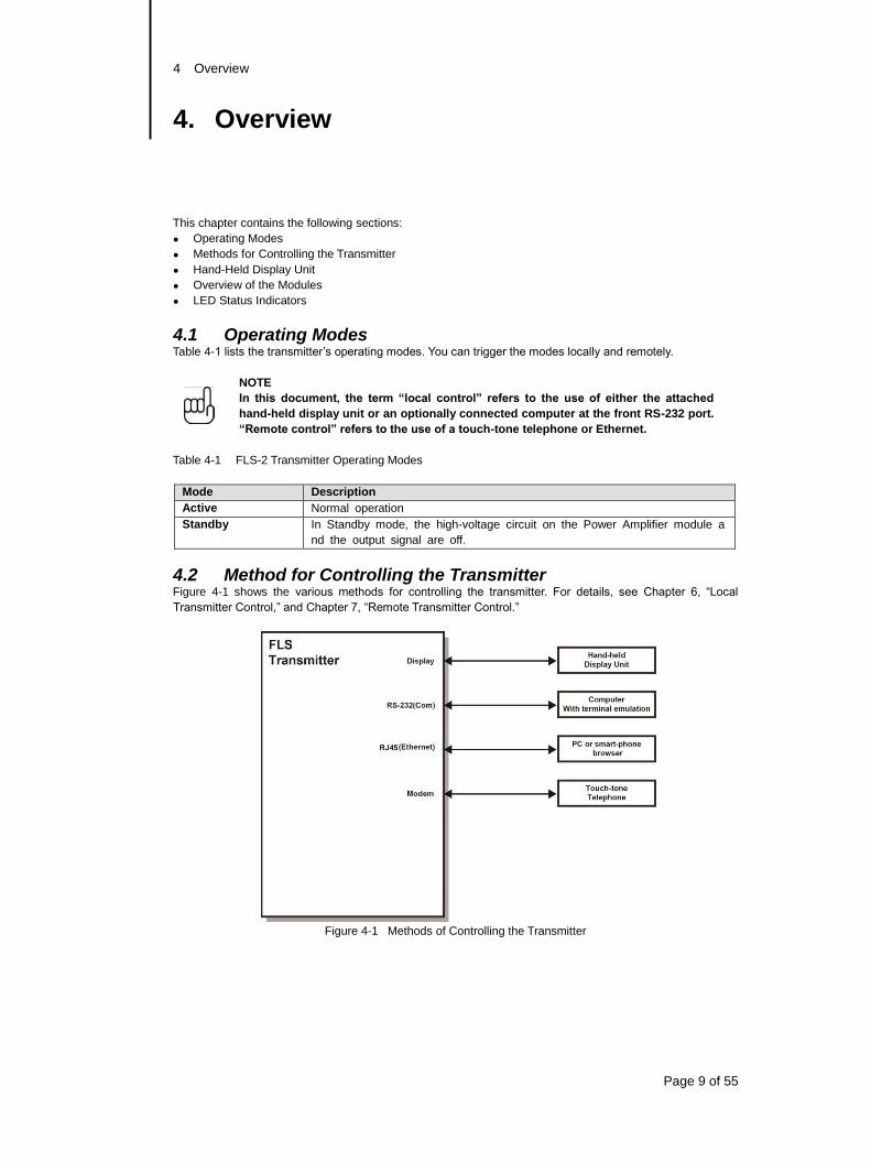
4.2 Method for Controlling the Transmitter Figure 4-1 shows the various methods for controlling the transmitter. For details, see Chapter 6, “Local
Transmitter Control,” and Chapter 7, “Remote Transmitter Control.”
Figure 4-1 Methods of Controlling the Transmitter
4 Overview
Page 10 of 55
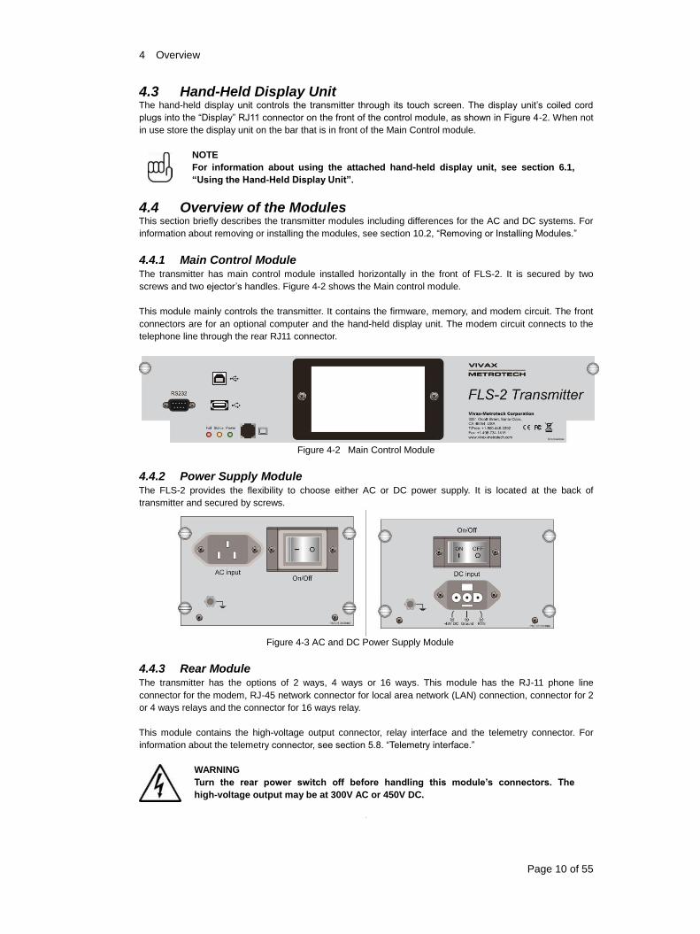
4.3 Hand-Held Display Unit The hand-held display unit controls the transmitter through its touch screen. The display unit’s coiled cord
plugs into the “Display” RJ11 connector on the front of the control module, as shown in Figure 4-2. When not
in use store the display unit on the bar that is in front of the Main Control module.
NOTE
For information about using the attached hand-held display unit, see section 6.1,
“Using the Hand-Held Display Unit”.
4.4 Overview of the Modules This section briefly describes the transmitter modules including differences for the AC and DC systems. For
information about removing or installing the modules, see section 10.2, “Removing or Installing Modules.”
4.4.1 Main Control Module The transmitter has main control module installed horizontally in the front of FLS-2. It is secured by two
screws and two ejector’s handles. Figure 4-2 shows the Main control module.
This module mainly controls the transmitter. It contains the firmware, memory, and modem circuit. The front
connectors are for an optional computer and the hand-held display unit. The modem circuit connects to the
telephone line through the rear RJ11 connector.
Figure 4-2 Main Control Module
4.4.2 Power Supply Module The FLS-2 provides the flexibility to choose either AC or DC power supply. It is located at the back of
transmitter and secured by screws.
Figure 4-3 AC and DC Power Supply Module
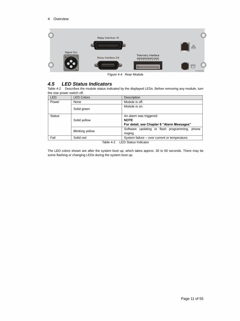
4.4.3 Rear Module The transmitter has the options of 2 ways, 4 ways or 16 ways. This module has the RJ-11 phone line
connector for the modem, RJ-45 network connector for local area network (LAN) connection, connector for 2
or 4 ways relays and the connector for 16 ways relay.
This module contains the high-voltage output connector, relay interface and the telemetry connector. For
information about the telemetry connector, see section 5.8. “Telemetry interface.”
WARNING
Turn the rear power switch off before handling this module’s connectors. The
high-voltage output may be at 300V AC or 450V DC.
4 Overview
Page 11 of 55
Figure 4-4 Rear Module
4.5 LED Status Indicators Table 4-2 Describes the module status indicated by the displayed LEDs. Before removing any module, turn
the rear power switch off.
LED LED Colors Description
Power None Module is off.
Solid green Module is on.
Status
Solid yellow
An alarm was triggered.
NOTE
For detail, see Chapter 6 “Alarm Messages”
Blinking yellow Software updating or flash programming, phone
ringing
Fail Solid red System failure – over current or temperature.
Table 4-2 LED Status Indicator
The LED colors shown are after the system boot up, which takes approx. 30 to 60 seconds. There may be
some flashing or changing LEDs during the system boot up.
5 Installing and Transmitter
Page 12 of 55
5. Installing the Transmitter
This chapter contains the following sections:
Installation Site
Required Tools and Test Equipment
Unpacking the Transmitter
Output Connector Pin-Out
Attaching the Rack Mounting Brackets
Installing or Replacing the Transmitter
Testing the Transmitter.
Telemetry Interface
NOTE
Before installing the transmitter, first read the General Safety instructions and this
entire chapter.
5.1 Installation Site The installation site for the transmitter should meet the environment and power requirements listed in Table
3-1, “FLS-2 transmitter Specifications”.
5.2 Required Tools and Test Equipment Before installing the transmitter, ensure that you have the items listed in Table 5-1.
Name Image
Crescent wrench, or 7/16 in
wrench or nut drive
Pliers
Screwdriver, Philips-head #2
Volt meter
Table 5-1 Tools and Test Equipment
5.3 Unpacking the Transmitter Bring the boxed transmitter to the installation site. Carefully remove the contents from the shipping container.
Verify that you have the following items:
FLS-2 transmitter
Standard rack mounting bracket kit, one set each of 19 in.
Adjustable rack mounting bracket kit, 23 inches, 24 inches, adaptor plates (6), and assembly hardware.
Hand-held display unit with coiled cable and stylus.
AC or DC power cord, depending on the ordered configuration Modem cable, 6ft
This Operating Manual
5 Installing and Transmitter
Page 13 of 55
NOTE
If there are any missing or damaged parts, contact technical support. If you need to
return the transmitter, carefully repack all items, and then contact technical support
for an RMA number.
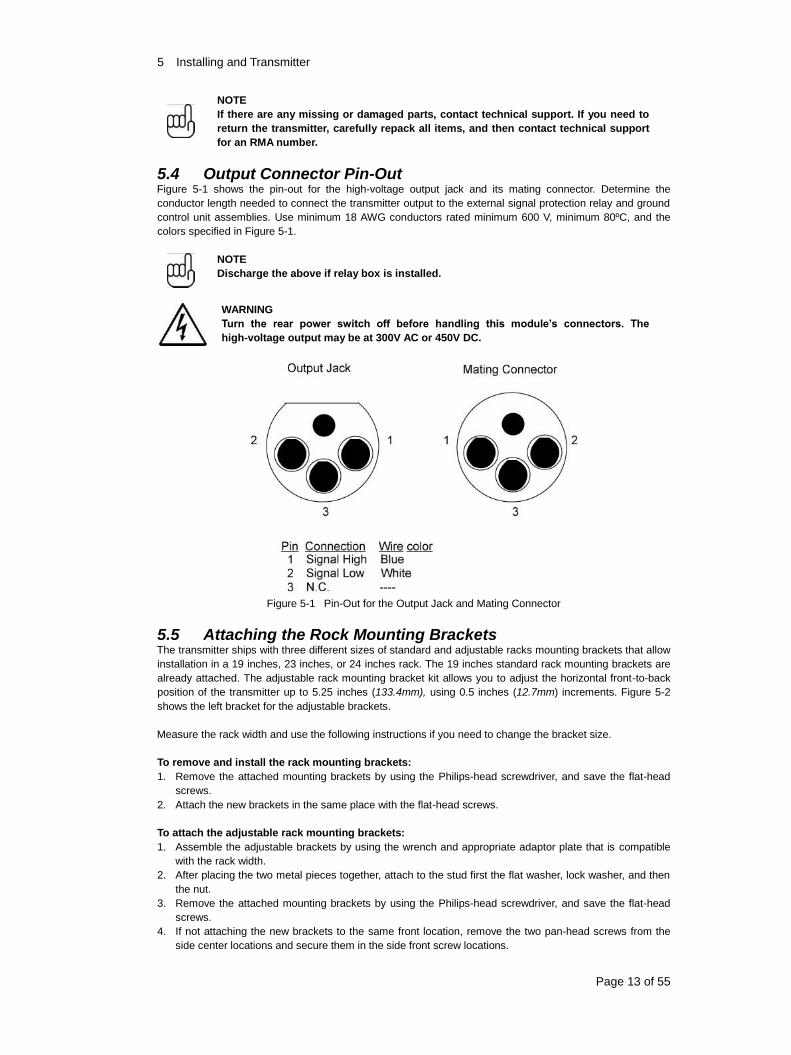
5.4 Output Connector Pin-Out Figure 5-1 shows the pin-out for the high-voltage output jack and its mating connector. Determine the
conductor length needed to connect the transmitter output to the external signal protection relay and ground
control unit assemblies. Use minimum 18 AWG conductors rated minimum 600 V, minimum 80ºC, and the
colors specified in Figure 5-1.
NOTE
Discharge the above if relay box is installed.
WARNING
Turn the rear power switch off before handling this module’s connectors. The
high-voltage output may be at 300V AC or 450V DC.
Figure 5-1 Pin-Out for the Output Jack and Mating Connector
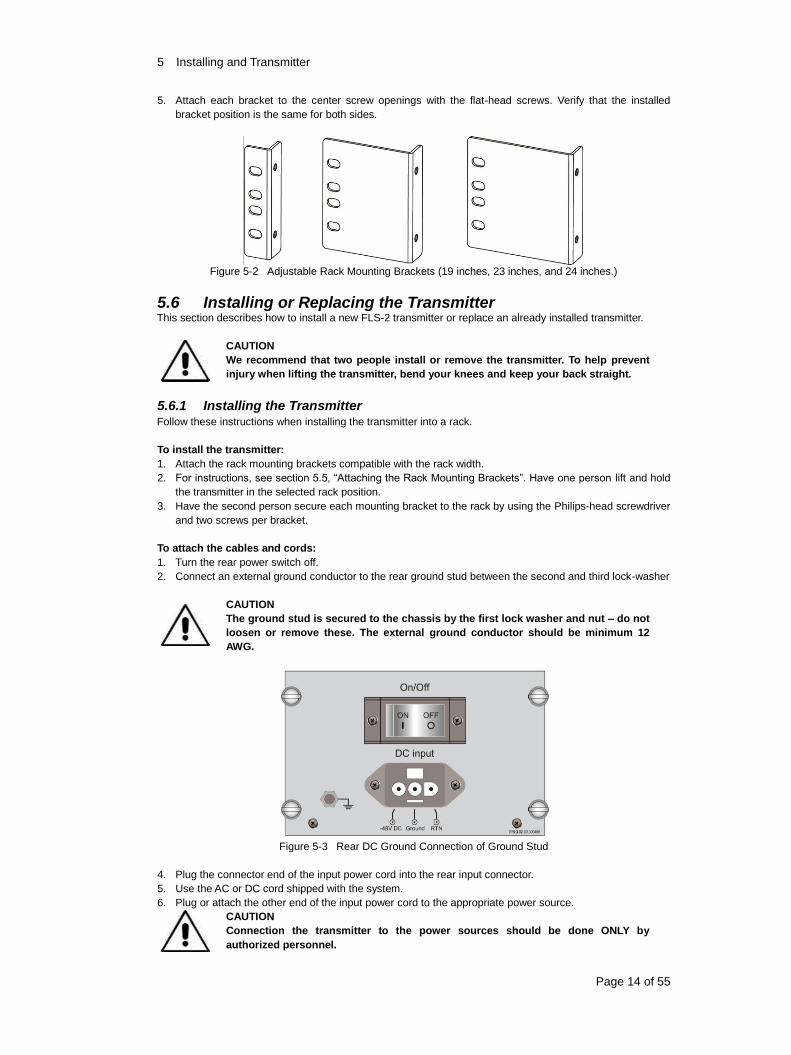
5.5 Attaching the Rock Mounting Brackets The transmitter ships with three different sizes of standard and adjustable racks mounting brackets that allow
installation in a 19 inches, 23 inches, or 24 inches rack. The 19 inches standard rack mounting brackets are
already attached. The adjustable rack mounting bracket kit allows you to adjust the horizontal front-to-back
position of the transmitter up to 5.25 inches (133.4mm), using 0.5 inches (12.7mm) increments. Figure 5-2
shows the left bracket for the adjustable brackets.
Measure the rack width and use the following instructions if you need to change the bracket size.
To remove and install the rack mounting brackets:
1. Remove the attached mounting brackets by using the Philips-head screwdriver, and save the flat-head
screws.
2. Attach the new brackets in the same place with the flat-head screws.
To attach the adjustable rack mounting brackets:
1. Assemble the adjustable brackets by using the wrench and appropriate adaptor plate that is compatible
with the rack width.
2. After placing the two metal pieces together, attach to the stud first the flat washer, lock washer, and then
the nut.
3. Remove the attached mounting brackets by using the Philips-head screwdriver, and save the flat-head
screws.
4. If not attaching the new brackets to the same front location, remove the two pan-head screws from the
side center locations and secure them in the side front screw locations.
5 Installing and Transmitter
Page 14 of 55
5. Attach each bracket to the center screw openings with the flat-head screws. Verify that the installed
bracket position is the same for both sides.
Figure 5-2 Adjustable Rack Mounting Brackets (19 inches, 23 inches, and 24 inches.)
5.6 Installing or Replacing the Transmitter This section describes how to install a new FLS-2 transmitter or replace an already installed transmitter.
CAUTION
We recommend that two people install or remove the transmitter. To help prevent
injury when lifting the transmitter, bend your knees and keep your back straight.
5.6.1 Installing the Transmitter Follow these instructions when installing the transmitter into a rack.
To install the transmitter:
1. Attach the rack mounting brackets compatible with the rack width.
2. For instructions, see section 5.5, “Attaching the Rack Mounting Brackets”. Have one person lift and hold
the transmitter in the selected rack position.
3. Have the second person secure each mounting bracket to the rack by using the Philips-head screwdriver
and two screws per bracket.
To attach the cables and cords:
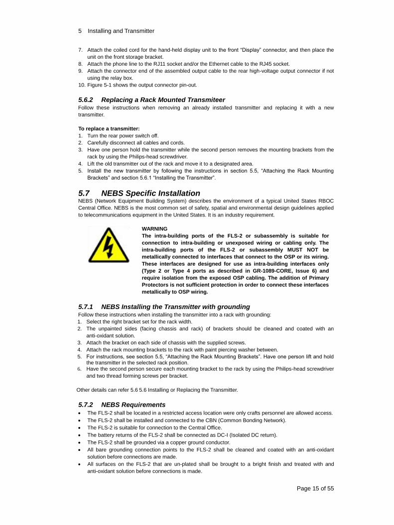
1. Turn the rear power switch off.
2. Connect an external ground conductor to the rear ground stud between the second and third lock-washer
CAUTION
The ground stud is secured to the chassis by the first lock washer and nut – do not
loosen or remove these. The external ground conductor should be minimum 12
AWG.
Figure 5-3 Rear DC Ground Connection of Ground Stud
4. Plug the connector end of the input power cord into the rear input connector.
5. Use the AC or DC cord shipped with the system.
6. Plug or attach the other end of the input power cord to the appropriate power source.
CAUTION
Connection the transmitter to the power sources should be done ONLY by
authorized personnel.
5 Installing and Transmitter
Page 15 of 55
7. Attach the coiled cord for the hand-held display unit to the front “Display” connector, and then place the
unit on the front storage bracket.
8. Attach the phone line to the RJ11 socket and/or the Ethernet cable to the RJ45 socket.
9. Attach the connector end of the assembled output cable to the rear high-voltage output connector if not
using the relay box.
10. Figure 5-1 shows the output connector pin-out.
5.6.2 Replacing a Rack Mounted Transmiteer Follow these instructions when removing an already installed transmitter and replacing it with a new
transmitter.
To replace a transmitter:
1. Turn the rear power switch off.
2. Carefully disconnect all cables and cords.
3. Have one person hold the transmitter while the second person removes the mounting brackets from the
rack by using the Philips-head screwdriver.
4. Lift the old transmitter out of the rack and move it to a designated area.
5. Install the new transmitter by following the instructions in section 5.5, “Attaching the Rack Mounting
Brackets” and section 5.6.1 “Installing the Transmitter”.
5.7 NEBS Specific Installation NEBS (Network Equipment Building System) describes the environment of a typical United States RBOC
Central Office. NEBS is the most common set of safety, spatial and environmental design guidelines applied
to telecommunications equipment in the United States. It is an industry requirement.
WARNING
The intra-building ports of the FLS-2 or subassembly is suitable for
connection to intra-building or unexposed wiring or cabling only. The
intra-building ports of the FLS-2 or subassembly MUST NOT be
metallically connected to interfaces that connect to the OSP or its wiring.
These interfaces are designed for use as intra-building interfaces only
(Type 2 or Type 4 ports as described in GR-1089-CORE, Issue 6) and
require isolation from the exposed OSP cabling. The addition of Primary
Protectors is not sufficient protection in order to connect these interfaces
metallically to OSP wiring.
5.7.1 NEBS Installing the Transmitter with grounding Follow these instructions when installing the transmitter into a rack with grounding:
1. Select the right bracket set for the rack width.
2. The unpainted sides (facing chassis and rack) of brackets should be cleaned and coated with an
anti-oxidant solution.
3. Attach the bracket on each side of chassis with the supplied screws.
4. Attach the rack mounting brackets to the rack with paint piercing washer between.
5. For instructions, see section 5.5, “Attaching the Rack Mounting Brackets”. Have one person lift and hold the transmitter in the selected rack position.
6. Have the second person secure each mounting bracket to the rack by using the Philips-head screwdriver
and two thread forming screws per bracket.
Other details can refer 5.6 5.6 Installing or Replacing the Transmitter.
5.7.2 NEBS Requirements
The FLS-2 shall be located in a restricted access location were only crafts personnel are allowed access.
The FLS-2 shall be installed and connected to the CBN (Common Bonding Network).
The FLS-2 is suitable for connection to the Central Office.
The battery returns of the FLS-2 shall be connected as DC-I (Isolated DC return).
The FLS-2 shall be grounded via a copper ground conductor.
All bare grounding connection points to the FLS-2 shall be cleaned and coated with an anti-oxidant
solution before connections are made.
All surfaces on the FLS-2 that are un-plated shall be brought to a bright finish and treated with and
anti-oxidant solution before connections is made.
5 Installing and Transmitter
Page 16 of 55
All non-conductive surfaces on the FLS-2 shall be removed from all threads and connection points to
ensure electrical continuity.
The FLS-2 utilizes two side rack mounting brackets with two thread forming screws and two paint piercing
washers on each side secure it the on frame. The grounding is through the rack frame.
The FLS-2 is capable of operating 48 Vdc at a maximum current level 3 A with a 10 A built-in circuit
breaker protection.
5.8 Testing the Transmitter After installing the transmitter and the line protection and control equipment, conduct the following tests to
ensure that the transmitter operates properly;
Check the modules’ LEDs for normal operation per section 4.5, “LED Status Indicators.”
Use a receiver to locate the energized line to ensure that the signal transmits correctly.
5.9 Telemetry Interface Table 5-2 lists the pin designations of the rear telemetry interface connector. The connections are in pairs,
such as A-B, C-D, and so on. Use insulated conductors sized 14-28 AWG. This document excludes
instructions for wiring the mating connector and its end-use connections.
NOTE
When the telemetry interface controls the transmitter, the hand-held display screen
shows a telephone icon.
Pin Description
A West Relay
B Ground
C East Relay
D Ground
E Fault High
F Fault Low
G Active High Auxiliary
H Active Low Auxiliary
I Remote Enable High
J Remote Enable Low
Table 5-2 Telemetry Connections
6 Local-Transmitter Control
Page 17 of 55
6. Local Transmitter Control
This chapter contains the following sections:
Using the Hand-Held Display Unit.
Using the RS-232 Port.
NOTE
If someone tries to remotely control the transmitter while being controlled locally, only
the local user can control the transmitter.
6.1 Using the Hand-Held Display Unit This section describes how to program the transmitter and view the status of its functions by using the
hand-held display unit.
After turning on the transmitter, the following appears on the welcome screen for approximately 40 sec:
product model (FLS-2), product type (Vivax-Metrotech Utility Transmitter), ISO 9001: 2000 Certified, and the
firmware version number. The Main Operation screen appears next and is the Home page for the display unit.
NOTE
After 3 min. Of inactivity, the display unit enters Sleep mode with a dimmed screen.
Touch the screen to resume use.
The section discusses the following:
Main Operating Screen.
Operating Mode Menu.
Installation Sequence.
Utilities Menu.
Edit Menu.
6.1.1 Main Operating Screen The Main Operating screen is the home page for the display unit. From here, you can program the Menu,
Lines and also change the operating mode between Standby and Active. When in Active mode, the center
displays the voltage, current, power and resistance values for the locate signals.
When the transmitter’s line configuration is W&E (FLS-2-TX2W), press the Lines button to toggle the display
among the West, East, and W&E line parameters. If the configuration is not W&E, the button is dimmed.
For 4 ways (FLS-2-TX4W) and 16 ways (FLS-2-TX16W), press the Lines button to go into the Select Lines
screen.
To select an operational mode
The transmitter has two operating modes; see section 4.1 “Operating Modes”. The transmitter enters Standby
mode when powered up. To determine the transmitter’s operational mode, look for the status name (Standby
or Active) on the Main Operating screen.
On the Main Operating screen, click either ACTIVE or STANDBY. The status changes to the enabled
mode.
6 Local-Transmitter Control
Page 18 of 55
Figure 6-1 Main Operating Screen (Standby Mode and Active Mode)
NOTE
The active and standby buttons appear differently than the buttons on the other screens.
For a description of the various buttons, see “Document Conventions” on page 4.
Main Operating Screen – Alarm Screen status
When the current exceeding/below the preset limits the display will show an Alarm Screen.
Figure 6-2 Alarm Screen
Main Operating Screen during DTMF connection
The Phone icon will appear on the bottom left side of the screen when it is operating thru DTMF Phone.
Figure 6-3 Main Operating Screen – Phone Icon
Main Operating Screen during RS-232 connection
The terminal icon will appear on the bottom left side of the screen when it is operating thru RS-232 locally.
6 Local-Transmitter Control
Page 19 of 55
Figure 6-4 Main Operating Screen – Phone Icon
Main Operating Screen during modem dials in connection
The modem icon will appear on the bottom left side of the screen when it is operating through modem dial
in connection.
Figure 6-5 Main Operating Screen – Modem Icon
6.1.2 Operating Mode Menu In this section, you learn how:
To select a line
To select a line frequency
To set timer
To set the line alarm levels
To set the line output current level
To load user setup
NOTE
These instructions are written using the common abbreviated method to move you
from one screen to another. For example, click Start > Control Panel > Printers.
To select a line
On the Main Operating screen, click Lines, and then select the line. Click OK to confirm and return to the
Main Operating screen.
Figure 6-6 Select Lines (FLS-2-TX4W) / (FLS-2-TX16W).
For the 2 ways FLS, pressing “Lines” will toggle between the installed lines (East, West or East&West)
6 Local-Transmitter Control
Page 20 of 55
To select a line frequency
1. On the Main Operating screen, click Menu, and then select the frequency. The display unit automatically
saves the selection when switching screens.
Figure 6-7 Operating Mode Menu – 5, 3, and 10 frequencies
2. Do one of the following:
Click OK to return to the Main Operating screen.
Program the other setup functions.
To set timer
1. On the Main Operating screen, click Menu > Timer.
Figure 6-8 Set Timer (Hours)
2. Select the hours for the FLS-2 to operate. For non-stop operating click Continuous.
3. Click Enter to confirm the selection.
To set the line alarm levels
1. On the Main Operating screen, click Menu > Alarm.
Figure 6-9 Line Alarm Levels
2. Program each alarm current value by doing the following:
a) Click the alarm name.
b) Click the double (greater change) and single (smaller change) arrow icons to set the value.
c) Click Enter to save or Cancel to exit without saving.
3. Do one of the following:
a) Click OK to return to the Main Operating screen.
b) Program the other setup features.
6 Local-Transmitter Control
Page 21 of 55
To set the line output current level
1. On the Main Operating screen, click Menu > Output Adjust.
Figure 6-10 Output Current Level
2. Program output current valve by clicking the double and single arrow icons.
3. Click Enter to save and go to Set Output Current screen or Cancel to exit without saving.
NOTE: This feature is available only in the ACTIVE mode!
Figure 6-11 Set Output Current
4. Do one of the following:
a) Click OK to return to the Main Operating screen.
b) Program the other setup features.
To load user setup
1. On the Main Operating screen, click Menu > User Setup.
Figure 6-12 Load User Setup
2. Click on the numeric number to load the saved user setup. The setting description will display on top while
clicking each setup.
3. Click Enter to load or Cancel to exit without loading.
4. Do one of the following:
5. Click OK to return to the Main Operating screen.
6. Program the other setup features.
6 Local-Transmitter Control
Page 22 of 55
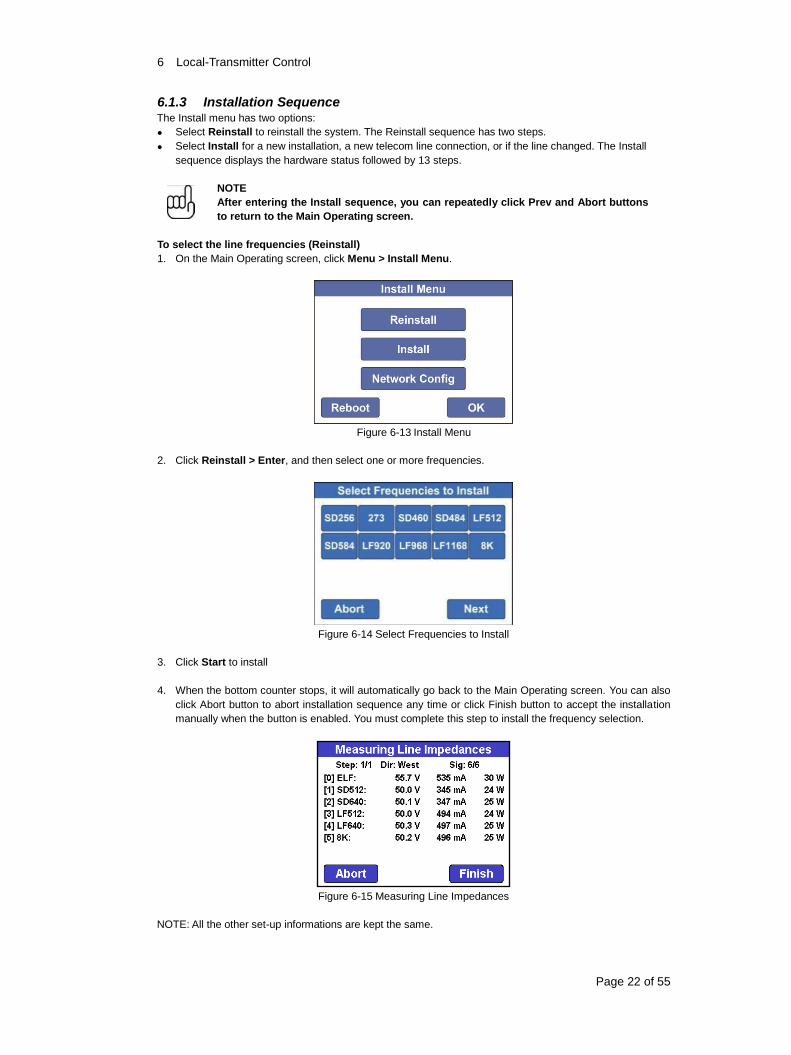
6.1.3 Installation Sequence The Install menu has two options:
Select Reinstall to reinstall the system. The Reinstall sequence has two steps.
Select Install for a new installation, a new telecom line connection, or if the line changed. The Install
sequence displays the hardware status followed by 13 steps.
NOTE
After entering the Install sequence, you can repeatedly click Prev and Abort buttons
to return to the Main Operating screen.
To select the line frequencies (Reinstall)
1. On the Main Operating screen, click Menu > Install Menu.
Figure 6-13 Install Menu
2. Click Reinstall > Enter, and then select one or more frequencies.
Figure 6-14 Select Frequencies to Install
3. Click Start to install
4. When the bottom counter stops, it will automatically go back to the Main Operating screen. You can also
click Abort button to abort installation sequence any time or click Finish button to accept the installation
manually when the button is enabled. You must complete this step to install the frequency selection.
Figure 6-15 Measuring Line Impedances
NOTE: All the other set-up informations are kept the same.
6 Local-Transmitter Control
Page 23 of 55
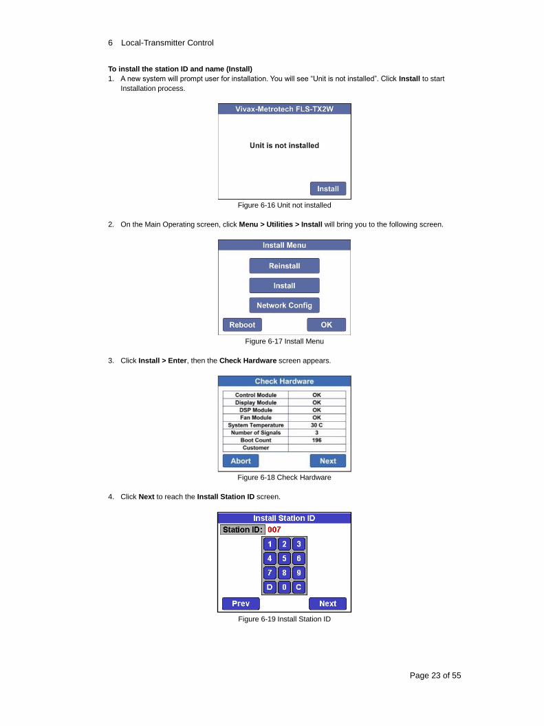
To install the station ID and name (Install)
1. A new system will prompt user for installation. You will see “Unit is not installed”. Click Install to start
Installation process.
Figure 6-16 Unit not installed
2. On the Main Operating screen, click Menu > Utilities > Install will bring you to the following screen.
Figure 6-17 Install Menu
3. Click Install > Enter, then the Check Hardware screen appears.
Figure 6-18 Check Hardware
4. Click Next to reach the Install Station ID screen.
Figure 6-19 Install Station ID
6 Local-Transmitter Control
Page 24 of 55
5. Enter the station ID, using C to clear the entry or D to delete the last character, and then click Next.
Figure 6-20 Install Station Name
6. Enter the station name, and then click Next.
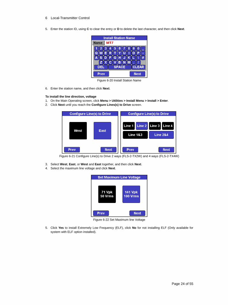
To install the line direction, voltage
1. On the Main Operating screen, click Menu > Utilities > Install Menu > Install > Enter.
2. Click Next until you reach the Configure Lines(s) to Drive screen.
Figure 6-21 Configure Line(s) to Drive 2 ways (FLS-2-TX2W) and 4 ways (FLS-2-TX4W)
3. Select West, East, or West and East together, and then click Next.
4. Select the maximum line voltage and click Next.
Figure 6-22 Set Maximum line Voltage
5. Click Yes to install Extremely Low Frequency (ELF), click No for not installing ELF (Only available for
system with ELF option installed).
6 Local-Transmitter Control
Page 25 of 55
Figure 6-23 ELF Installation Confirmation Screen
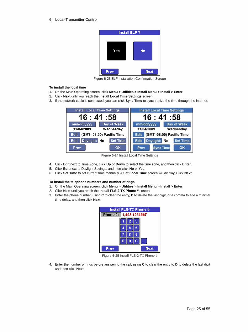
To install the local time
1. On the Main Operating screen, click Menu > Utilities > Install Menu > Install > Enter.
2. Click Next until you reach the Install Local Time Settings screen.
3. If the network cable is connected, you can click Sync Time to synchronize the time through the internet.
Figure 6-24 Install Local Time Settings
4. Click Edit next to Time Zone, click Up or Down to select the time zone, and then click Enter.
5. Click Edit next to Daylight Savings, and then click No or Yes.
6. Click Set Time to set current time manually. A Set Local Time screen will display. Click Next.
To install the telephone numbers and number of rings
1. On the Main Operating screen, click Menu > Utilities > Install Menu > Install > Enter.
2. Click Next until you reach the Install FLS-2-TX Phone # screen.
3. Enter the phone number, using C to clear the entry, D to delete the last digit, or a comma to add a minimal
time delay, and then click Next.
Figure 6-25 Install FLS-2-TX Phone #
4. Enter the number of rings before answering the call, using C to clear the entry to D to delete the last digit
and then click Next.
6 Local-Transmitter Control
Page 26 of 55
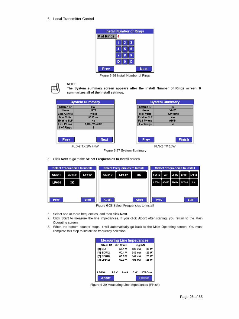
Figure 6-26 Install Number of Rings
NOTE
The System summary screen appears after the Install Number of Rings screen. It
summarizes all of the install settings.
FLS-2 TX 2W / 4W FLS-2 TX 16W
Figure 6-27 System Summary
5. Click Next to go to the Select Frequencies to Install screen.
Figure 6-28 Select Frequencies to Install
6. Select one or more frequencies, and then click Next.
7. Click Start to measure the line impedances. If you click Abort after starting, you return to the Main
Operating screen.
8. When the bottom counter stops, it will automatically go back to the Main Operating screen. You must
complete this step to install the frequency selection.
Figure 6-29 Measuring Line Impedances (Finish)
6 Local-Transmitter Control
Page 27 of 55
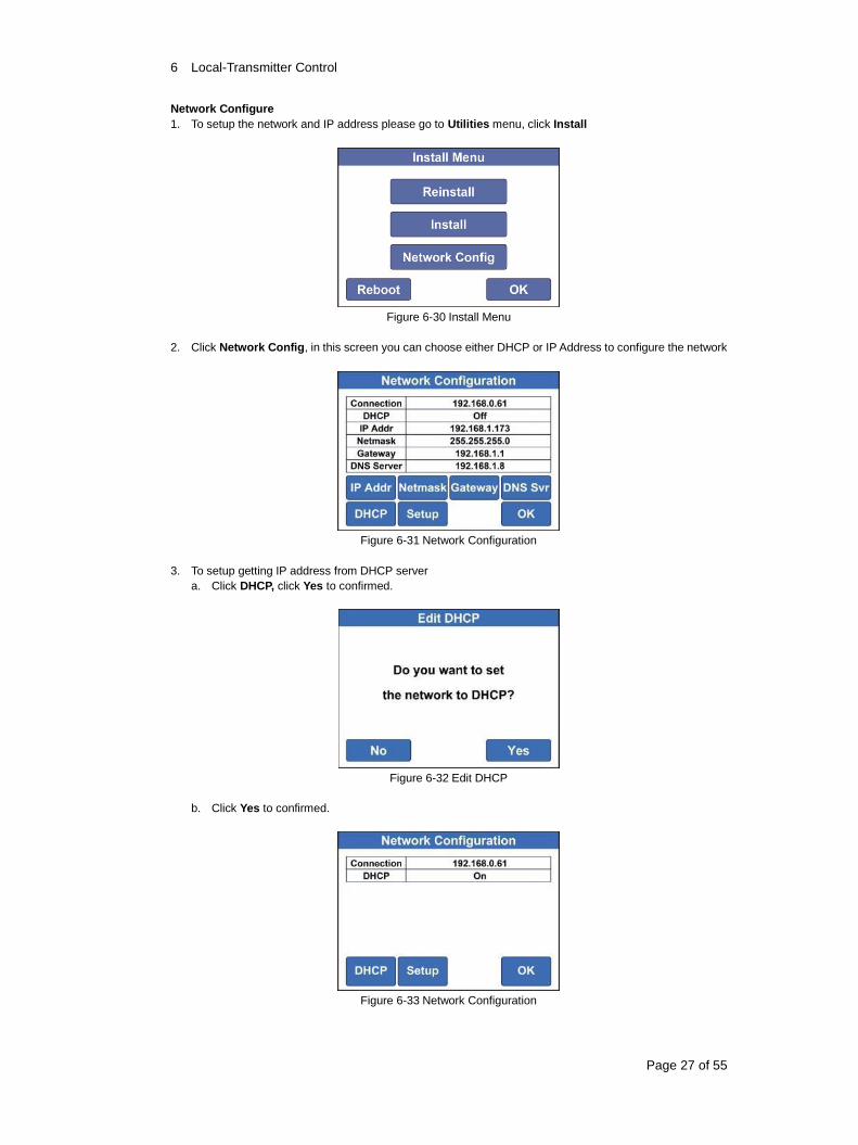
Network Configure
1. To setup the network and IP address please go to Utilities menu, click Install
Figure 6-30 Install Menu
2. Click Network Config, in this screen you can choose either DHCP or IP Address to configure the network
Figure 6-31 Network Configuration
3. To setup getting IP address from DHCP server
a. Click DHCP, click Yes to confirmed.
Figure 6-32 Edit DHCP
b. Click Yes to confirmed.
Figure 6-33 Network Configuration
6 Local-Transmitter Control
Page 28 of 55
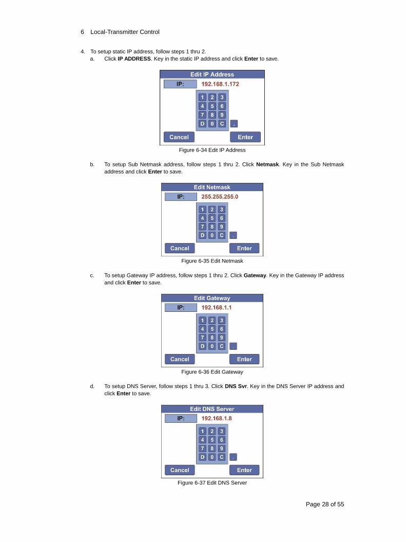
4. To setup static IP address, follow steps 1 thru 2.
a. Click IP ADDRESS. Key in the static IP address and click Enter to save.
Figure 6-34 Edit IP Address
b. To setup Sub Netmask address, follow steps 1 thru 2. Click Netmask. Key in the Sub Netmask
address and click Enter to save.
Figure 6-35 Edit Netmask
c. To setup Gateway IP address, follow steps 1 thru 2. Click Gateway. Key in the Gateway IP address
and click Enter to save.
Figure 6-36 Edit Gateway
d. To setup DNS Server, follow steps 1 thru 3. Click DNS Svr. Key in the DNS Server IP address and
click Enter to save.
Figure 6-37 Edit DNS Server
6 Local-Transmitter Control
Page 29 of 55
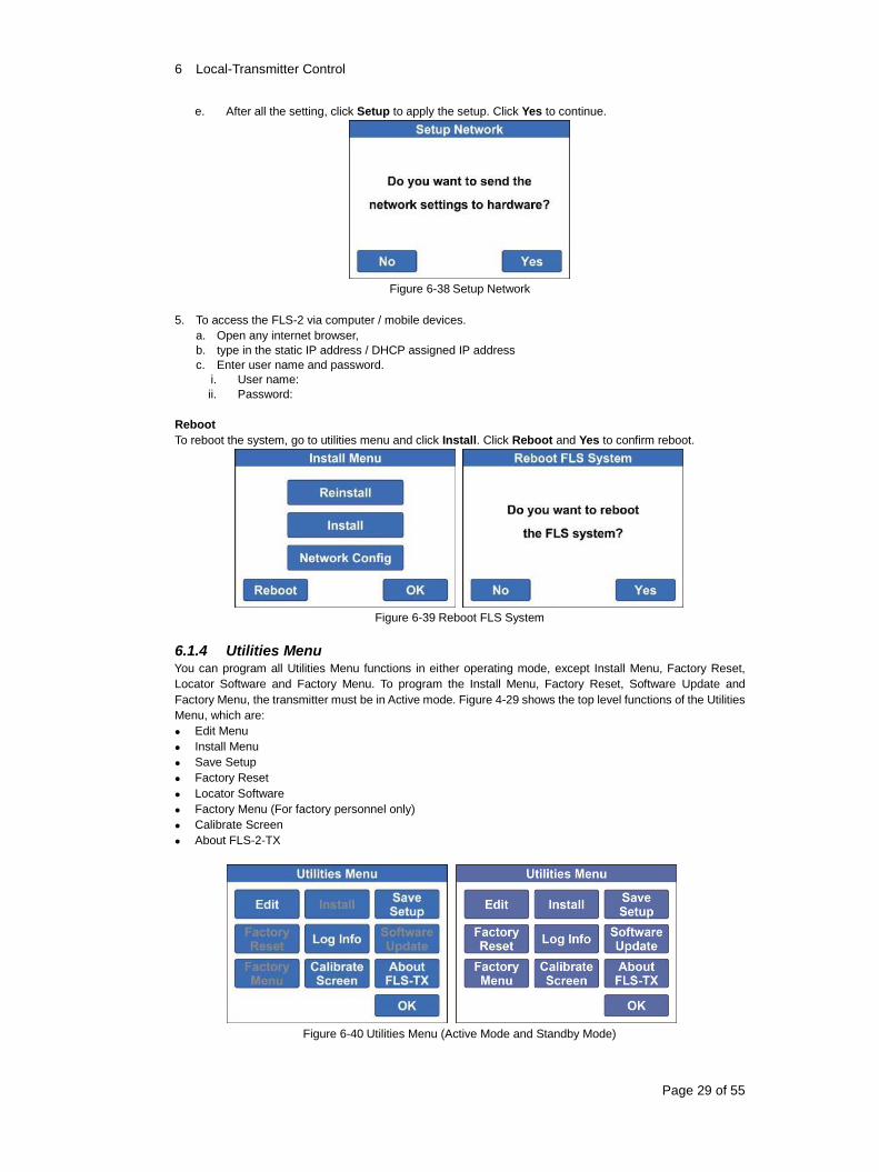
e. After all the setting, click Setup to apply the setup. Click Yes to continue.
Figure 6-38 Setup Network
5. To access the FLS-2 via computer / mobile devices.
a. Open any internet browser,
b. type in the static IP address / DHCP assigned IP address
c. Enter user name and password.
i. User name:
ii. Password:
Reboot
To reboot the system, go to utilities menu and click Install. Click Reboot and Yes to confirm reboot.
Figure 6-39 Reboot FLS System
6.1.4 Utilities Menu You can program all Utilities Menu functions in either operating mode, except Install Menu, Factory Reset,
Locator Software and Factory Menu. To program the Install Menu, Factory Reset, Software Update and
Factory Menu, the transmitter must be in Active mode. Figure 4-29 shows the top level functions of the Utilities
Menu, which are:
Edit Menu
Install Menu
Save Setup
Factory Reset
Locator Software
Factory Menu (For factory personnel only)
Calibrate Screen
About FLS-2-TX
Figure 6-40 Utilities Menu (Active Mode and Standby Mode)
6 Local-Transmitter Control
Page 30 of 55
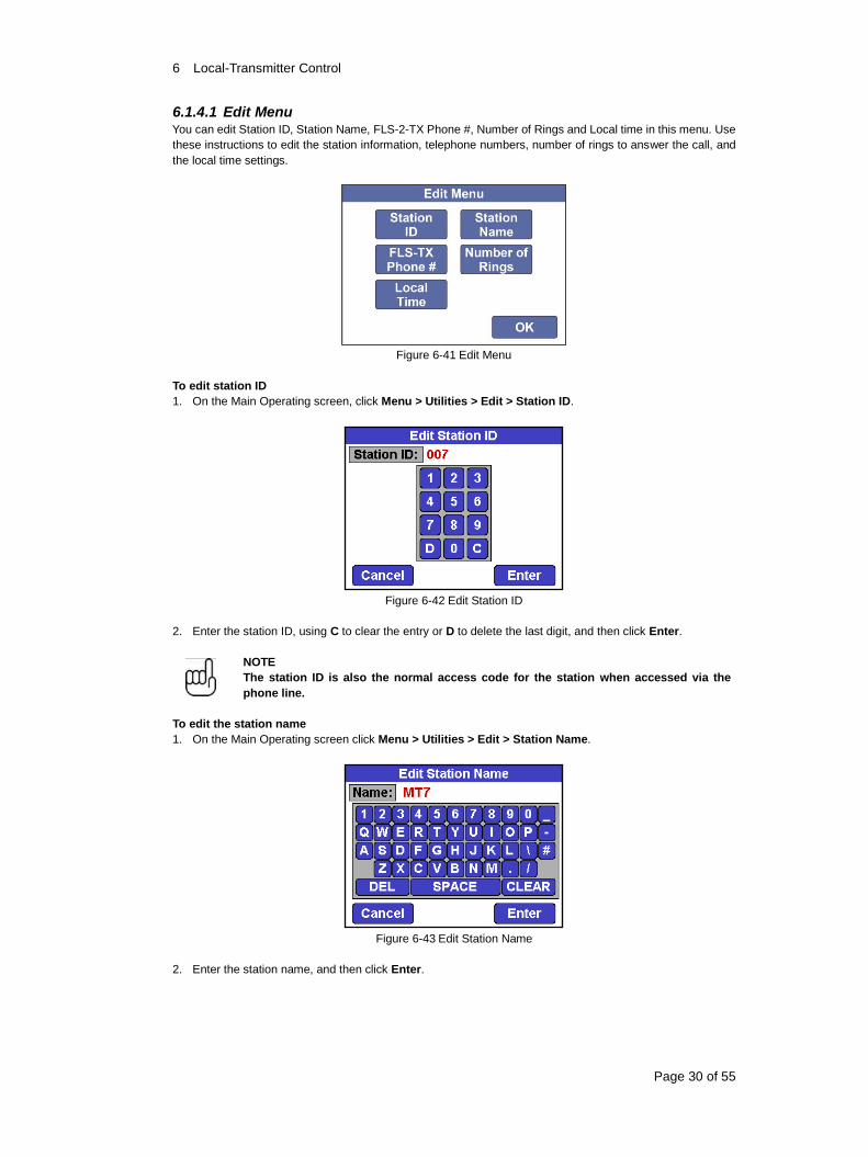
6.1.4.1 Edit Menu You can edit Station ID, Station Name, FLS-2-TX Phone #, Number of Rings and Local time in this menu. Use
these instructions to edit the station information, telephone numbers, number of rings to answer the call, and
the local time settings.
Figure 6-41 Edit Menu
To edit station ID
1. On the Main Operating screen, click Menu > Utilities > Edit > Station ID.
Figure 6-42 Edit Station ID
2. Enter the station ID, using C to clear the entry or D to delete the last digit, and then click Enter.
NOTE
The station ID is also the normal access code for the station when accessed via the
phone line.
To edit the station name
1. On the Main Operating screen click Menu > Utilities > Edit > Station Name.
Figure 6-43 Edit Station Name
2. Enter the station name, and then click Enter.
6 Local-Transmitter Control
Page 31 of 55
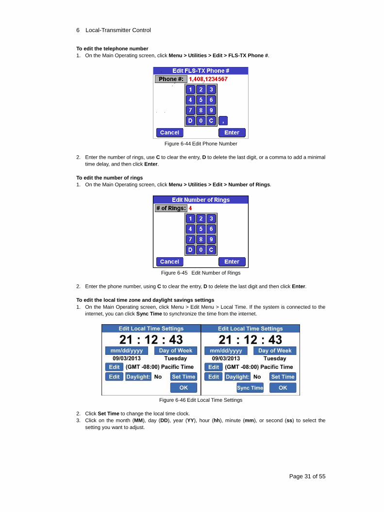
To edit the telephone number
1. On the Main Operating screen, click Menu > Utilities > Edit > FLS-TX Phone #.
Figure 6-44 Edit Phone Number
2. Enter the number of rings, use C to clear the entry, D to delete the last digit, or a comma to add a minimal
time delay, and then click Enter.
To edit the number of rings
1. On the Main Operating screen, click Menu > Utilities > Edit > Number of Rings.
Figure 6-45 Edit Number of Rings
2. Enter the phone number, using C to clear the entry, D to delete the last digit and then click Enter.
To edit the local time zone and daylight savings settings
1. On the Main Operating screen, click Menu > Edit Menu > Local Time. If the system is connected to the
internet, you can click Sync Time to synchronize the time from the internet.
Figure 6-46 Edit Local Time Settings
2. Click Set Time to change the local time clock.
3. Click on the month (MM), day (DD), year (YY), hour (hh), minute (mm), or second (ss) to select the
setting you want to adjust.
6 Local-Transmitter Control
Page 32 of 55
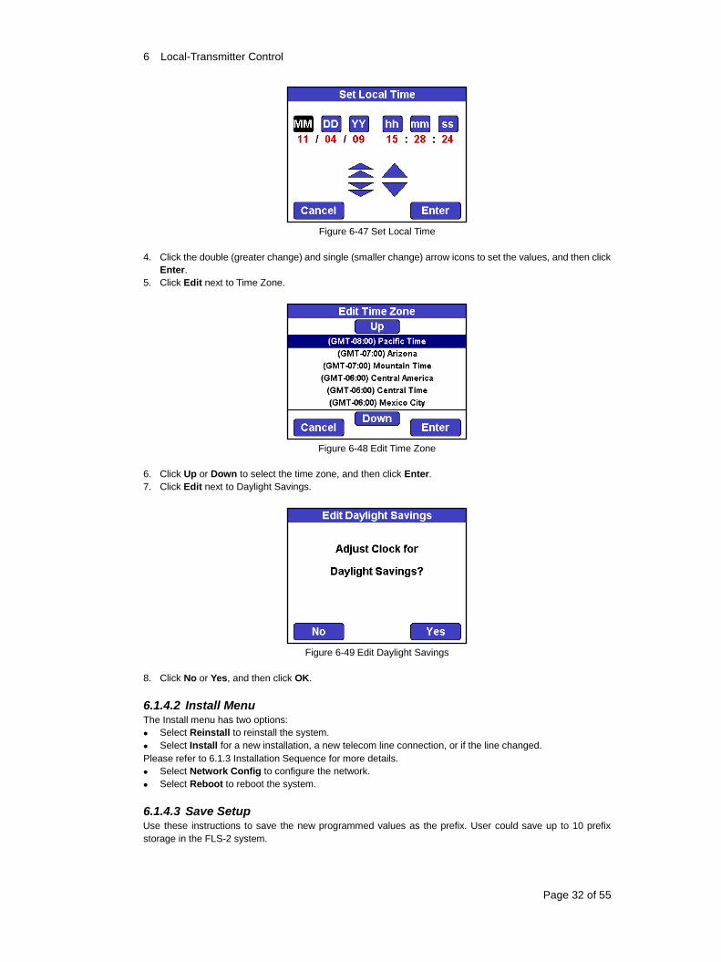
Figure 6-47 Set Local Time
4. Click the double (greater change) and single (smaller change) arrow icons to set the values, and then click
Enter.
5. Click Edit next to Time Zone.
Figure 6-48 Edit Time Zone
6. Click Up or Down to select the time zone, and then click Enter.
7. Click Edit next to Daylight Savings.
Figure 6-49 Edit Daylight Savings
8. Click No or Yes, and then click OK.
6.1.4.2 Install Menu The Install menu has two options:
Select Reinstall to reinstall the system.
Select Install for a new installation, a new telecom line connection, or if the line changed.
Please refer to 6.1.3 Installation Sequence for more details.
Select Network Config to configure the network.
Select Reboot to reboot the system.
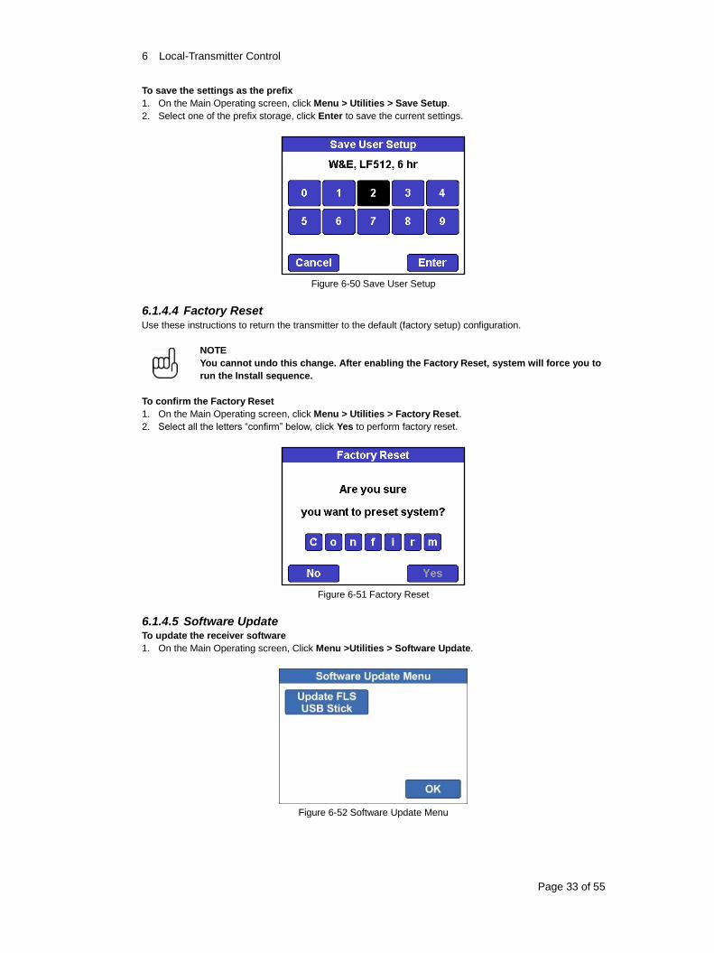
6.1.4.3 Save Setup Use these instructions to save the new programmed values as the prefix. User could save up to 10 prefix
storage in the FLS-2 system.
6 Local-Transmitter Control
Page 33 of 55
To save the settings as the prefix
1. On the Main Operating screen, click Menu > Utilities > Save Setup.
2. Select one of the prefix storage, click Enter to save the current settings.
Figure 6-50 Save User Setup
6.1.4.4 Factory Reset Use these instructions to return the transmitter to the default (factory setup) configuration.
NOTE
You cannot undo this change. After enabling the Factory Reset, system will force you to
run the Install sequence.
To confirm the Factory Reset
1. On the Main Operating screen, click Menu > Utilities > Factory Reset.
2. Select all the letters “confirm” below, click Yes to perform factory reset.
Figure 6-51 Factory Reset
6.1.4.5 Software Update To update the receiver software
1. On the Main Operating screen, Click Menu >Utilities > Software Update.
Figure 6-52 Software Update Menu
6 Local-Transmitter Control
Page 34 of 55
2. Click Update FLS USB Stick to update the software. The update process will take 1 minute.
Figure 6-53 FLS SW Update by USB Stick
3. Once the update is finished, the system will reboot automatically.
6.1.4.6 Calibrate Screen Use these instructions to calibrate the display unit’s touch screen.
To calibrate the touch screen
1. On the Main Operating screen, click Menu > Utilities > Calibrate Screen.
Figure 6-54 Calibrate Screen
2. Use the stylus to click the marker where it appears on the screen. These are two tests with the marker
placed in different corners.
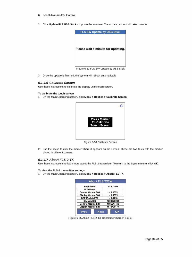
6.1.4.7 About FLS-2-TX Use these instructions to learn more about the FLS-2 transmitter. To return to the System menu, click OK.
To view the FLS-2 transmitter settings
1. On the Main Operating screen, click Menu > Utilities > About FLS-TX.
Figure 6-55 About FLS-2-TX Transmitter (Screen 1 of 3)
6 Local-Transmitter Control
Page 35 of 55
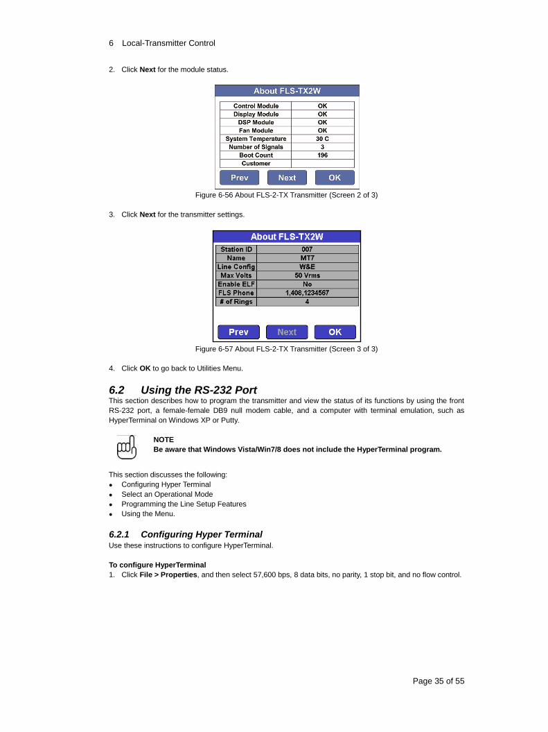
2. Click Next for the module status.
Figure 6-56 About FLS-2-TX Transmitter (Screen 2 of 3)
3. Click Next for the transmitter settings.
Figure 6-57 About FLS-2-TX Transmitter (Screen 3 of 3)
4. Click OK to go back to Utilities Menu.
6.2 Using the RS-232 Port This section describes how to program the transmitter and view the status of its functions by using the front
RS-232 port, a female-female DB9 null modem cable, and a computer with terminal emulation, such as
HyperTerminal on Windows XP or Putty.
NOTE
Be aware that Windows Vista/Win7/8 does not include the HyperTerminal program.
This section discusses the following:
Configuring Hyper Terminal
Select an Operational Mode
Programming the Line Setup Features
Using the Menu.
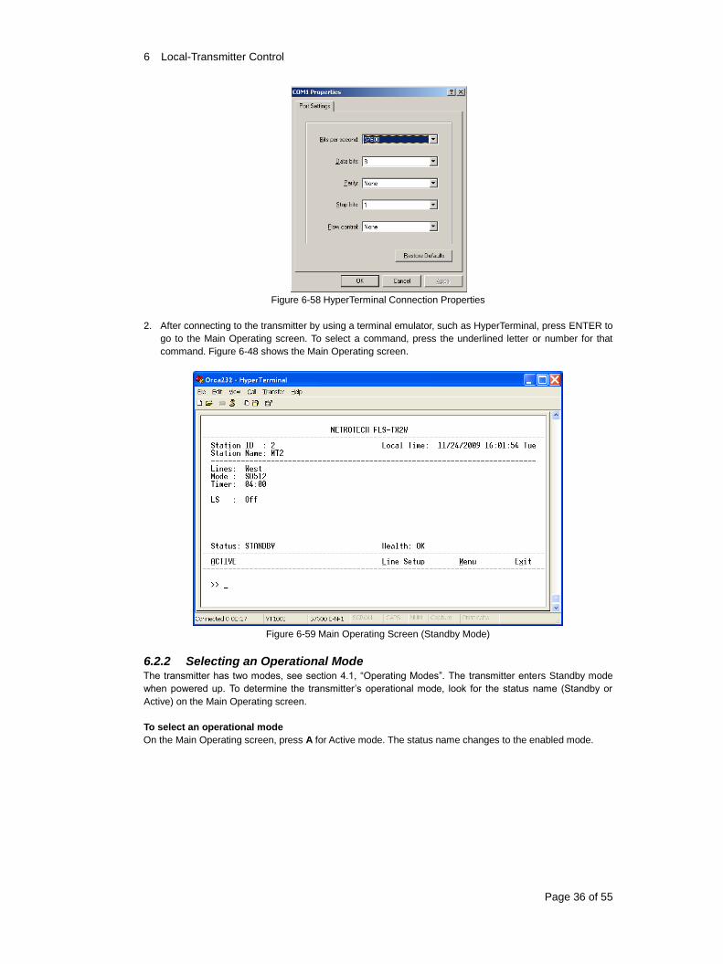
6.2.1 Configuring Hyper Terminal Use these instructions to configure HyperTerminal.
To configure HyperTerminal
1. Click File > Properties, and then select 57,600 bps, 8 data bits, no parity, 1 stop bit, and no flow control.
6 Local-Transmitter Control
Page 36 of 55
Figure 6-58 HyperTerminal Connection Properties
2. After connecting to the transmitter by using a terminal emulator, such as HyperTerminal, press ENTER to
go to the Main Operating screen. To select a command, press the underlined letter or number for that
command. Figure 6-48 shows the Main Operating screen.
Figure 6-59 Main Operating Screen (Standby Mode)
6.2.2 Selecting an Operational Mode The transmitter has two modes, see section 4.1, “Operating Modes”. The transmitter enters Standby mode
when powered up. To determine the transmitter’s operational mode, look for the status name (Standby or
Active) on the Main Operating screen.
To select an operational mode
On the Main Operating screen, press A for Active mode. The status name changes to the enabled mode.
6 Local-Transmitter Control
Page 37 of 55
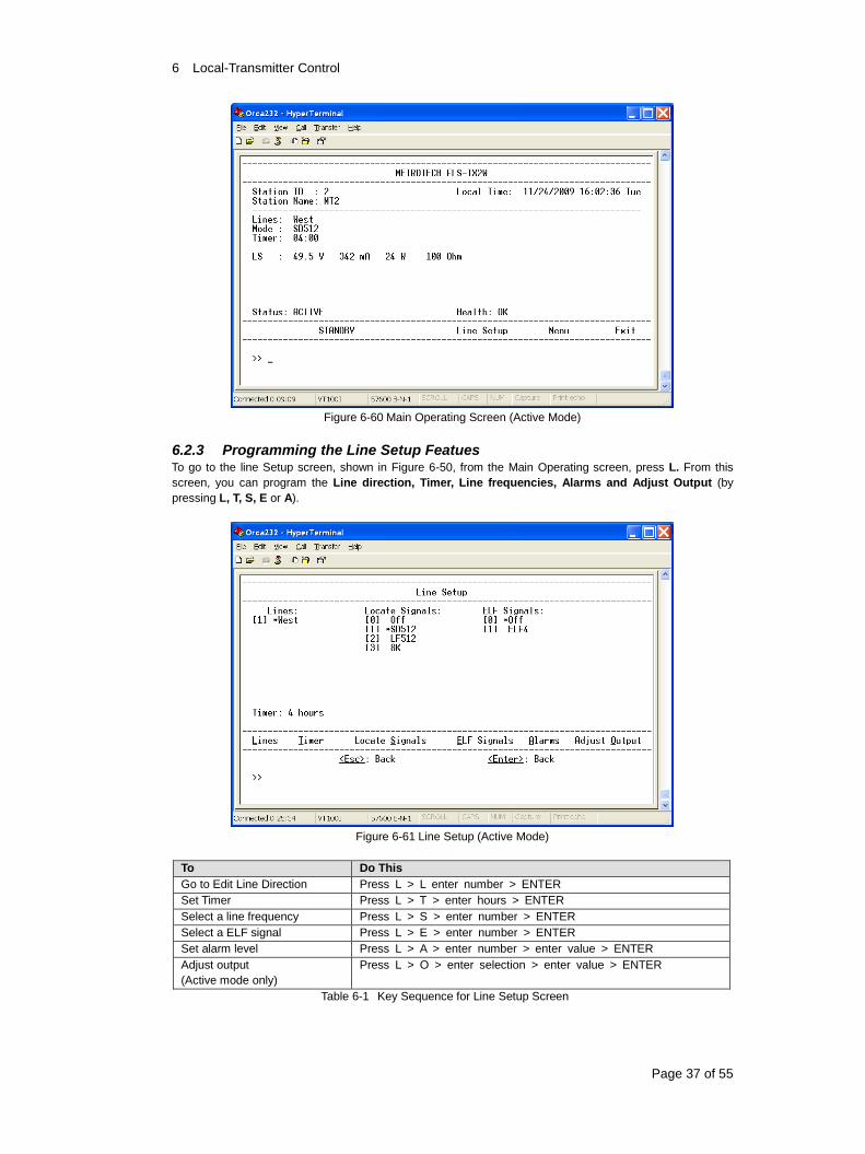
Figure 6-60 Main Operating Screen (Active Mode)
6.2.3 Programming the Line Setup Featues To go to the line Setup screen, shown in Figure 6-50, from the Main Operating screen, press L. From this
screen, you can program the Line direction, Timer, Line frequencies, Alarms and Adjust Output (by
pressing L, T, S, E or A).
Figure 6-61 Line Setup (Active Mode)
To Do This
Go to Edit Line Direction Press L > L enter number > ENTER
Set Timer Press L > T > enter hours > ENTER
Select a line frequency Press L > S > enter number > ENTER
Select a ELF signal Press L > E > enter number > ENTER
Set alarm level Press L > A > enter number > enter value > ENTER
Adjust output
(Active mode only)
Press L > O > enter selection > enter value > ENTER
Table 6-1 Key Sequence for Line Setup Screen
6 Local-Transmitter Control
Page 38 of 55
To program Line Alarm Levels
On the Main Operating Screen press L > A > enter number > enter value > ENTER Figure 6-51 shows the
Line Alarm Levels screen. From this screen, program the minimum, nominal and maximum alarms currents
for the locate signal.
Figure 6-62 Line Alarm Levels
To program the Output level (Active Mode Only)
On the Main Operating Screen press L > O > enter value.
NOTE
If you want to use the default ±20% tolerances for the minimum and maximum values,
program the LS and ES outputs first to automatically adjust the minimum and maximum
values. After that, you can change the minimum and/or maximum values manually if
necessary.
Figure 6-63 Output Current Level
6 Local-Transmitter Control
Page 39 of 55
6.2.4 Using the Menu The System Menu screen, shown in Figure 6-53, has the following functions:
Edit Menu
Factory Reset (Standby Mode Only)
Locator Software (Standby Mode Only)
Install (Standby Mode Only)
Reinstall (Standby Mode Only)
Save Setup
About FLS-2-TX
Figure 6-64 Utilities Menu (Active)
Figure 6-65 Utilities Menu (Standby)
6 Local-Transmitter Control
Page 40 of 55
6.2.4.1 Locator software (Currently not available future features)
Figure 6-55 shows the Edit Menu screen. Use this screen to edit the Station ID, Number of Ring, Station
Name, Local Time and FLS-2-TX Phone #.
Figure 6-66 Edit Menu
Table 6-2 lists the sequence of pressed keys associated with each edit task, starting from the Main Operating
screen.
After entering the applicable data, press ENTER to save and return to the Edit menu.
To Do This
Edit Station ID Press M > E > I > enter ID > ENTER
Edit Number of Rings Press M > E > R > enter number > ENTER
Edit Station Name Press M > E > N > enter name > ENTER
Edit Local Time
Edit Time Zone
Edit Daylight Savings
Edit Date
Edit Time
Press M > E > T >enter selection
Press M > E > T > Z > enter number > ENTER
Press M > E > T > S > enter value > ENTER
Press M > E > T > D > enter date > ENTER
Press M > E > T > T > enter time > ENTER
Edit FLS-2-TX Phone # Press M > E > P > enter number > ENTER
Table 6-2 Key Sequence for Edit Menu Screen
6.2.4.2 Factory Reset Use these instructions while in Standby mode to return the transmitter to the factory default configuration.
NOTE
You cannot undo this change. After enabling the factory reset, you have to run the
Install sequence.
To reset the transmitter
1. On the Main Operating screen, press M > F.
6 Local-Transmitter Control
Page 41 of 55
Figure 6-67 Factory Reset
2. Type confirm, and then press ENTER.
6.2.4.3 Locator Software (Standby Mode Only) (Currently not available, future features)
Use these instructions while in Standby mode to sync firmware.
To sync the firmware or logs to accessory equipment
1. From the Main Operating Screen, press M > C.
Figure 6-68 Locator Software
2. Do one of the following:
Press S to sync the Software.
Press L to sync the logs.
3. Press ESC or ENTER.
6 Local-Transmitter Control
Page 42 of 55
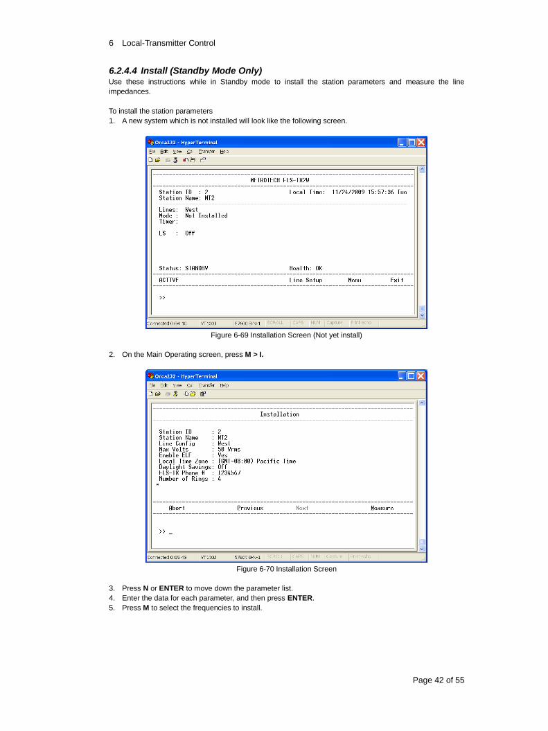
6.2.4.4 Install (Standby Mode Only) Use these instructions while in Standby mode to install the station parameters and measure the line
impedances.
To install the station parameters
1. A new system which is not installed will look like the following screen.
Figure 6-69 Installation Screen (Not yet install)
2. On the Main Operating screen, press M > I.
Figure 6-70 Installation Screen
3. Press N or ENTER to move down the parameter list.
4. Enter the data for each parameter, and then press ENTER.
5. Press M to select the frequencies to install.
6 Local-Transmitter Control
Page 43 of 55
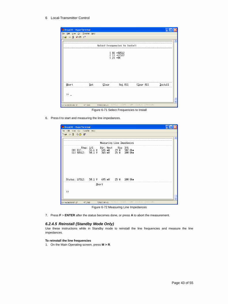
Figure 6-71 Select Frequencies to Install
6. Press I to start and measuring the line impedances.
Figure 6-72 Measuring Line Impedances
7. Press F > ENTER after the status becomes done, or press A to abort the measurement.
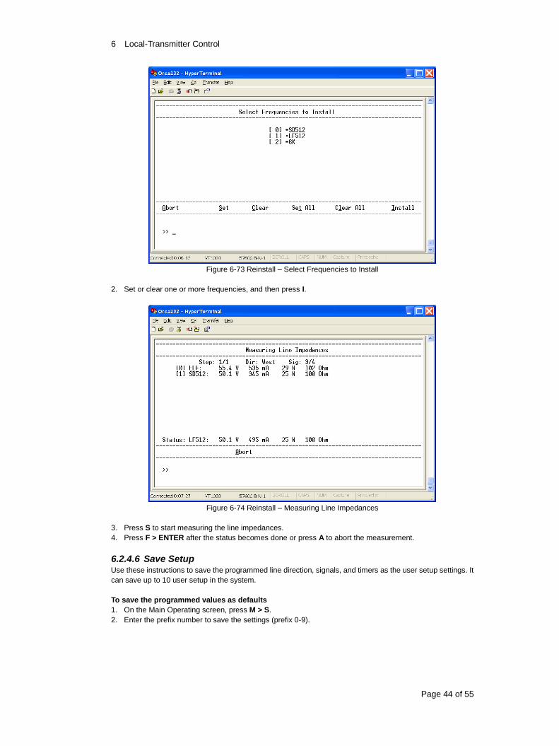
6.2.4.5 Reinstall (Standby Mode Only) Use these instructions while in Standby mode to reinstall the line frequencies and measure the line
impedances.
To reinstall the line frequencies
1. On the Main Operating screen, press M > R.
6 Local-Transmitter Control
Page 44 of 55
Figure 6-73 Reinstall – Select Frequencies to Install
2. Set or clear one or more frequencies, and then press I.
Figure 6-74 Reinstall – Measuring Line Impedances
3. Press S to start measuring the line impedances.
4. Press F > ENTER after the status becomes done or press A to abort the measurement.
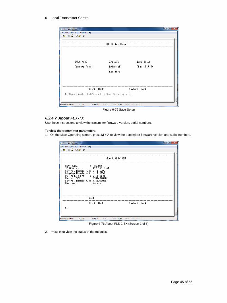
6.2.4.6 Save Setup Use these instructions to save the programmed line direction, signals, and timers as the user setup settings. It
can save up to 10 user setup in the system.
To save the programmed values as defaults
1. On the Main Operating screen, press M > S.
2. Enter the prefix number to save the settings (prefix 0-9).
6 Local-Transmitter Control
Page 45 of 55
Figure 6-75 Save Setup
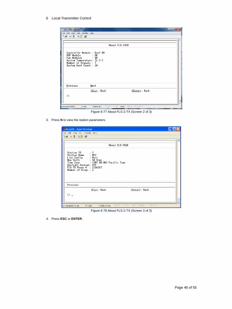
6.2.4.7 About FLX-TX Use these instructions to view the transmitter firmware version, serial numbers.
To view the transmitter parameters
1. On the Main Operating screen, press M > A to view the transmitter firmware version and serial numbers.
Figure 6-76 About FLS-2-TX (Screen 1 of 3)
2. Press N to view the status of the modules.
6 Local-Transmitter Control
Page 46 of 55
Figure 6-77 About FLS-2-TX (Screen 2 of 3)
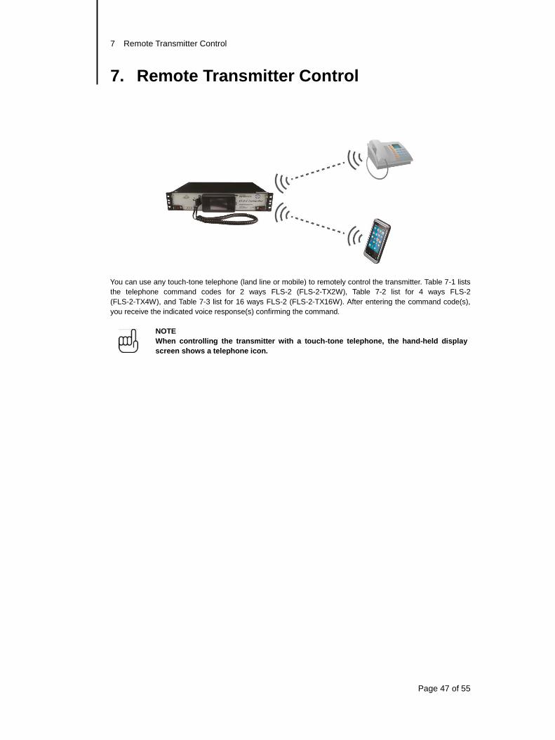
3. Press N to view the station parameters.
Figure 6-78 About FLS-2-TX (Screen 3 of 3)
4. Press ESC or ENTER.
7 Remote Transmitter Control
Page 47 of 55
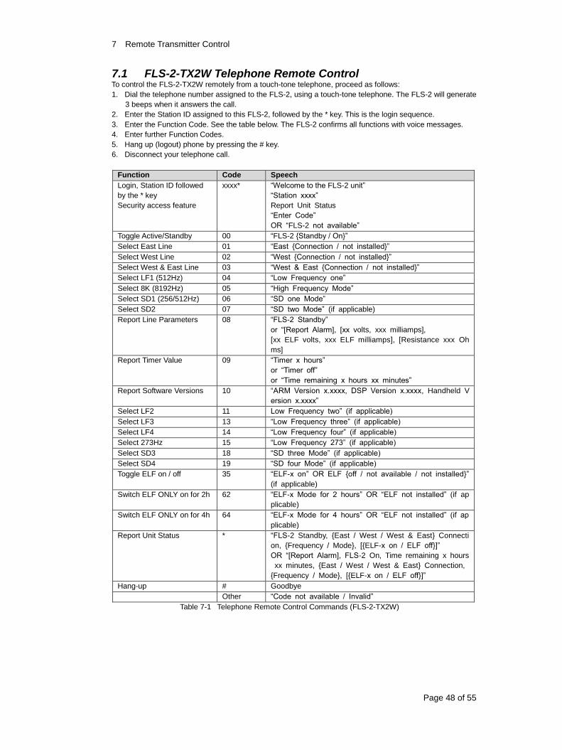
7. Remote Transmitter Control
You can use any touch-tone telephone (land line or mobile) to remotely control the transmitter. Table 7-1 lists
the telephone command codes for 2 ways FLS-2 (FLS-2-TX2W), Table 7-2 list for 4 ways FLS-2
(FLS-2-TX4W), and Table 7-3 list for 16 ways FLS-2 (FLS-2-TX16W). After entering the command code(s),
you receive the indicated voice response(s) confirming the command.
NOTE
When controlling the transmitter with a touch-tone telephone, the hand-held display
screen shows a telephone icon.
7 Remote Transmitter Control
Page 48 of 55
FLS-2-TX2W Telephone Remote Control 7.1To control the FLS-2-TX2W remotely from a touch-tone telephone, proceed as follows:
1. Dial the telephone number assigned to the FLS-2, using a touch-tone telephone. The FLS-2 will generate
3 beeps when it answers the call.
2. Enter the Station ID assigned to this FLS-2, followed by the * key. This is the login sequence.
3. Enter the Function Code. See the table below. The FLS-2 confirms all functions with voice messages.
4. Enter further Function Codes.
5. Hang up (logout) phone by pressing the # key.
6. Disconnect your telephone call.
Function Code Speech
Login, Station ID followed
by the * key
Security access feature
xxxx* “Welcome to the FLS-2 unit”
“Station xxxx”
Report Unit Status
“Enter Code”
OR “FLS-2 not available”
Toggle Active/Standby 00 “FLS-2 {Standby / On}”
Select East Line 01 “East {Connection / not installed}”
Select West Line 02 “West {Connection / not installed}”
Select West & East Line 03 “West & East {Connection / not installed}”
Select LF1 (512Hz) 04 “Low Frequency one”
Select 8K (8192Hz) 05 “High Frequency Mode”
Select SD1 (256/512Hz) 06 “SD one Mode”
Select SD2 07 “SD two Mode” (if applicable)
Report Line Parameters 08 “FLS-2 Standby”
or “[Report Alarm], [xx volts, xxx milliamps],
[xx ELF volts, xxx ELF milliamps], [Resistance xxx Oh
ms]
Report Timer Value 09 “Timer x hours”
or “Timer off”
or “Time remaining x hours xx minutes”
Report Software Versions 10 “ARM Version x.xxxx, DSP Version x.xxxx, Handheld V
ersion x.xxxx”
Select LF2 11 Low Frequency two” (if applicable)
Select LF3 13 “Low Frequency three” (if applicable)
Select LF4 14 “Low Frequency four” (if applicable)
Select 273Hz 15 “Low Frequency 273” (if applicable)
Select SD3 18 “SD three Mode” (if applicable)
Select SD4 19 “SD four Mode” (if applicable)
Toggle ELF on / off 35 “ELF-x on” OR ELF {off / not available / not installed}”
(if applicable)
Switch ELF ONLY on for 2h 62 “ELF-x Mode for 2 hours” OR “ELF not installed” (if ap
plicable)
Switch ELF ONLY on for 4h 64 “ELF-x Mode for 4 hours” OR “ELF not installed” (if ap
plicable)
Report Unit Status * “FLS-2 Standby, {East / West / West & East} Connecti
on, {Frequency / Mode}, [{ELF-x on / ELF off}]”
OR “[Report Alarm], FLS-2 On, Time remaining x hours
xx minutes, {East / West / West & East} Connection,
{Frequency / Mode}, [{ELF-x on / ELF off}]”
Hang-up # Goodbye
Other “Code not available / Invalid”
Table 7-1 Telephone Remote Control Commands (FLS-2-TX2W)
7 Remote Transmitter Control
Page 49 of 55
FLS-2-TX4W Telephone Remote Control 7.2To control the FLS-2-TX4W remotely from a touch-tone telephone, proceed as follows:
1. Dial the telephone number assigned to the FLS-2, using a touch-tone telephone. The FLS-2 will generate
3 beeps when it answers the call.
2. Enter the Station ID assigned to this FLS-2, followed by the * key. This is the login sequence.
3. Enter the Function Code. See the table below. The FLS-2 confirms all functions with voice messages.
4. Enter further Function Codes.
5. Hang up (logout) phone by pressing the # key.
6. Disconnect you telephone call.
Function Code Speech
Login, Station ID followed
by the * key,
Security access feature
xxxx* “Welcome to the FLS-2 unit”
“Station xxxx”
Report Unit Status
“Enter Code”
or “FLS-2 not available”
Toggle Active / Standby 00 “FLS-2 {Standby / On}”
Select LF1 (512Hz) 04 “Low Frequency one”
Select 8K (8192Hz) 05 “High Frequency Mode”
Select SD1 (256/512Hz) 06 “SD one Mode”
Select SD2 07 “SD two Mode” (if applicable)
Report Line Parameters 08 “FLS-2 Standby”
Or “[Report Alarm], [xx volts, xxx milliamps],
[xx ELF volts, xxx ELF milliamps], Resistance xxx Ohms”
Report Timer Value 09 “Timer x hours”
or “Timer off”
or “Tim remaining x hours xx minutes”
Report Software Version 10 “ARM Version x.xxxx, DSP Version x.xxxx, Handheld
Version x.xxxx”
Select LF2 11 “Low Frequency two” (if applicable)
Select LF3 13 “Low Frequency three” (if applicable)
Select LF4 14 “Low Frequency four” (if applicable)
Select 273Hz 15 “Low Frequency 273” (if applicable)
Select SD3 18 “SD three Mode” (if applicable)
Select SD4 19 “SD four Mode” (if applicable)
Toggle ELF on / off 35 “ELF on” or “ELF {off / not available / not installed}”
Select Line 1 21 “Line 1 {Connection / not installed}”
Select Line 2 22 “Line 2 {Connection / not installed}”
Select Line 3 23 “Line 3 {Connection / not installed}”
Select Line 4 24 “Line 4 {Connection / not installed}”
Select Line 1 & 3 25 “Line 1 & 3 {Connection / not installed}”
Select Line 2 & 4 26 “Line 2 & 4{Connection / not installed}”
Switch ELF ONLY on for 2h 62 “ELF Mode for 2 hours” or “ELF not installed” (if applicable)
Switch ELF ONLY on for 4h 64 “ELF Mode for 4 hours” or “ELF not installed” (if applicable)
Report Unit Status * “FLS-2 Standby Line Connection, {Frequency / Mode},[ELF
{on / off}”
Or “[Report Alarm], FLS-2 On Time remaining x hours xx
minutes, Line Connection, {Frequency / Mode}, [ELF {on /
off}]”
Hang-up # Goodbye
other “Code not available / Invalid”
Table 7-2 Telephone Remote Control Commands (FLS-2-TX4W)
7 Remote Transmitter Control
Page 50 of 55
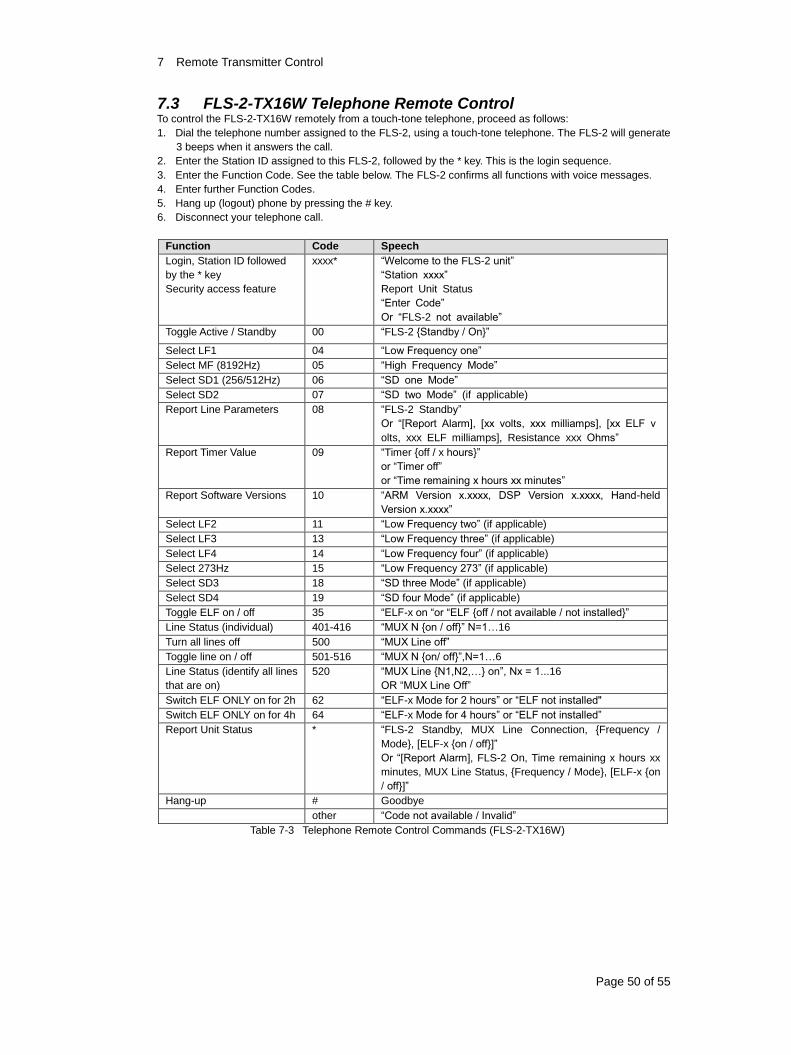
FLS-2-TX16W Telephone Remote Control 7.3To control the FLS-2-TX16W remotely from a touch-tone telephone, proceed as follows:
1. Dial the telephone number assigned to the FLS-2, using a touch-tone telephone. The FLS-2 will generate
3 beeps when it answers the call.
2. Enter the Station ID assigned to this FLS-2, followed by the * key. This is the login sequence.
3. Enter the Function Code. See the table below. The FLS-2 confirms all functions with voice messages.
4. Enter further Function Codes.
5. Hang up (logout) phone by pressing the # key.
6. Disconnect your telephone call.
Function Code Speech
Login, Station ID followed
by the * key
Security access feature
xxxx* “Welcome to the FLS-2 unit”
“Station xxxx”
Report Unit Status
“Enter Code”
Or “FLS-2 not available”
Toggle Active / Standby 00 “FLS-2 {Standby / On}”
Select LF1 04 “Low Frequency one”
Select MF (8192Hz) 05 “High Frequency Mode”
Select SD1 (256/512Hz) 06 “SD one Mode”
Select SD2 07 “SD two Mode” (if applicable)
Report Line Parameters 08 “FLS-2 Standby”
Or “[Report Alarm], [xx volts, xxx milliamps], [xx ELF v
olts, xxx ELF milliamps], Resistance xxx Ohms”
Report Timer Value 09 “Timer {off / x hours}”
or “Timer off”
or “Time remaining x hours xx minutes”
Report Software Versions 10 “ARM Version x.xxxx, DSP Version x.xxxx, Hand-held
Version x.xxxx”
Select LF2 11 “Low Frequency two” (if applicable)
Select LF3 13 “Low Frequency three” (if applicable)
Select LF4 14 “Low Frequency four” (if applicable)
Select 273Hz 15 “Low Frequency 273” (if applicable)
Select SD3 18 “SD three Mode” (if applicable)
Select SD4 19 “SD four Mode” (if applicable)
Toggle ELF on / off 35 “ELF-x on “or “ELF {off / not available / not installed}”
Line Status (individual) 401-416 “MUX N {on / off}” N=1…16
Turn all lines off 500 “MUX Line off”
Toggle line on / off 501-516 “MUX N {on/ off}”,N=1…6
Line Status (identify all lines
that are on)
520 “MUX Line {N1,N2,…} on”, Nx = 1...16
OR “MUX Line Off”
Switch ELF ONLY on for 2h 62 “ELF-x Mode for 2 hours” or “ELF not installed"
Switch ELF ONLY on for 4h 64 “ELF-x Mode for 4 hours” or “ELF not installed”
Report Unit Status * “FLS-2 Standby, MUX Line Connection, {Frequency /
Mode}, [ELF-x {on / off}]”
Or “[Report Alarm], FLS-2 On, Time remaining x hours xx
minutes, MUX Line Status, {Frequency / Mode}, [ELF-x {on
/ off}]”
Hang-up # Goodbye
other “Code not available / Invalid”
Table 7-3 Telephone Remote Control Commands (FLS-2-TX16W)
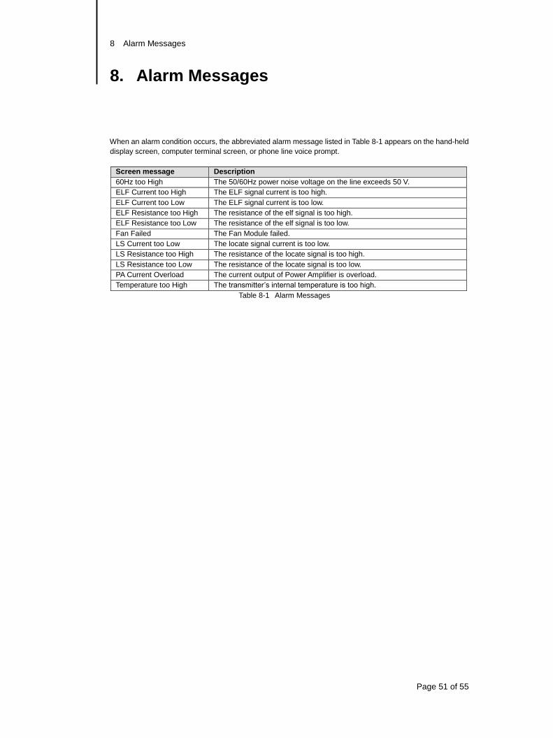
8 Alarm Messages
Page 51 of 55
8. Alarm Messages
When an alarm condition occurs, the abbreviated alarm message listed in Table 8-1 appears on the hand-held
display screen, computer terminal screen, or phone line voice prompt.
Screen message Description
60Hz too High The 50/60Hz power noise voltage on the line exceeds 50 V.
ELF Current too High The ELF signal current is too high.
ELF Current too Low The ELF signal current is too low.
ELF Resistance too High The resistance of the elf signal is too high.
ELF Resistance too Low The resistance of the elf signal is too low.
Fan Failed The Fan Module failed.
LS Current too Low The locate signal current is too low.
LS Resistance too High The resistance of the locate signal is too high.
LS Resistance too Low The resistance of the locate signal is too low.
PA Current Overload The current output of Power Amplifier is overload.
Temperature too High The transmitter’s internal temperature is too high.
Table 8-1 Alarm Messages
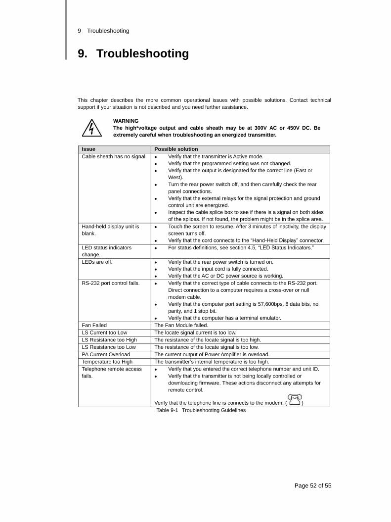
9 Troubleshooting
Page 52 of 55
9. Troubleshooting
This chapter describes the more common operational issues with possible solutions. Contact technical
support if your situation is not described and you need further assistance.
WARNING
The high*voltage output and cable sheath may be at 300V AC or 450V DC. Be
extremely careful when troubleshooting an energized transmitter.
Issue Possible solution
Cable sheath has no signal. Verify that the transmitter is Active mode.
Verify that the programmed setting was not changed.
Verify that the output is designated for the correct line (East or
West).
Turn the rear power switch off, and then carefully check the rear
panel connections.
Verify that the external relays for the signal protection and ground
control unit are energized.
Inspect the cable splice box to see if there is a signal on both sides
of the splices. If not found, the problem might be in the splice area.
Hand-held display unit is
blank.
Touch the screen to resume. After 3 minutes of inactivity, the display
screen turns off.
Verify that the cord connects to the “Hand-Held Display” connector.
LED status indicators
change.
For status definitions, see section 4.5, “LED Status Indicators.”
LEDs are off. Verify that the rear power switch is turned on.
Verify that the input cord is fully connected.
Verify that the AC or DC power source is working.
RS-232 port control fails. Verify that the correct type of cable connects to the RS-232 port.
Direct connection to a computer requires a cross-over or null
modem cable.
Verify that the computer port setting is 57,600bps, 8 data bits, no
parity, and 1 stop bit.
Verify that the computer has a terminal emulator.
Fan Failed The Fan Module failed.
LS Current too Low The locate signal current is too low.
LS Resistance too High The resistance of the locate signal is too high.
LS Resistance too Low The resistance of the locate signal is too low.
PA Current Overload The current output of Power Amplifier is overload.
Temperature too High The transmitter’s internal temperature is too high.
Telephone remote access
fails.
Verify that you entered the correct telephone number and unit ID.
Verify that the transmitter is not being locally controlled or
downloading firmware. These actions disconnect any attempts for
remote control.
Verify that the telephone line is connects to the modem. ( )
Table 9-1 Troubleshooting Guidelines
10 Maintenance
Page 53 of 55
10. Maintenance
This chapter contains the following sections:
Calibration
Removing or Installing Modules
Cleaning
NOTE
Read the General Safety instructions before starting any maintenance procedure.
10.1 Calibration Only the Main Control module requires calibration. For information, contact technical support.
10.2 Removing or Installing Modules This section describes how to remove and install the transmitter modules.
CAUTION
These modules are sensitive to electrostatic discharge (ESD). Do not touch the
board components.
To remove a module
1. Turn the transmitter’s rear power switch off.
2. Use a Philips-head screwdriver to loosen the two side screws.
3. Open (unlock) the module’s ejector handles by pressing in the red tabs and then moving the handles to
the outside position.
4. Hold the handles and slowly pull out the module.
To install a module
1. Turn the transmitter’s rear power switch off.
2. Open (unlock) the module’s ejector handles by pressing in the red tabs and then moving the handles to
the outside position
3. Hold the handles and carefully place the module into the proper slot’s side guide rails.
4. Slowly push the module into the slot opening until the face plate is flush with the classics.
5. Lock the handles by moving them to the inside position against the face plate.
6. Use a Philips-head screw driver to attach the two side screws.
10.3 Cleaning Routine cleaning should not be necessary because of the installation environment. However, if cleaning is
necessary, turn the rear power switch off and then use a slightly damp cloth. Do not let water drip into the
chassis or the hand-held display unit. Do not use cleaning chemicals.
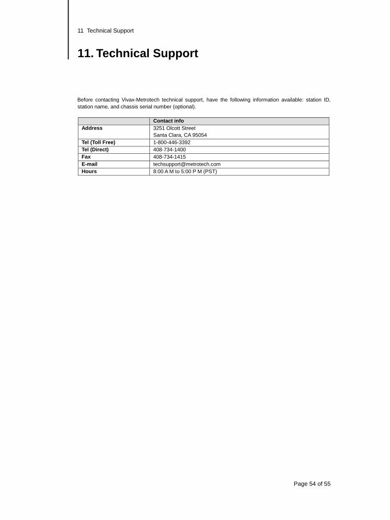
11 Technical Support
Page 54 of 55
11. Technical Support
Before contacting Vivax-Metrotech technical support, have the following information available: station ID,
station name, and chassis serial number (optional).
Contact info
Address 3251 Olcott Street
Santa Clara, CA 95054
Tel (Toll Free) 1-800-446-3392
Tel (Direct) 408-734-1400
Fax 408-734-1415
E-mail [email protected]
Hours 8:00 A M to 5:00 P M (PST)
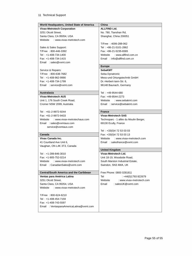
11 Technical Support
Page 55 of 55
World Headquaters, United State of America China
Vivax-Metrotech Corporation ALLFIND Ltd.
3251 Olcott Street, No. 780, Tianshan Rd,
Santa Clara, CA 95054, USA Shanghai, China 200051
Website : www.vivax-metrotech.com
T/Free : 4006-288-062
Sales & Sales Support: Tel : +86-21-5101-2862
T/Free : 800-446-3392 Fax : +86-21-5235-8365
Tel : +1-408-734-1400 Website : www.allfind.com.cn
Fax : +1-408-734-1415 Email : [email protected]
Email : [email protected]
Europe
Service & Repairs: SebaKMT
T/Free : 800-638-7682 Seba Dynatronic
Tel : +1-408-962-9990 Mess-und Ortungstechnik GmbH
Fax : +1-408-734-1799 Dr.-Herbert-Iann-Str. 6,
Email : [email protected] 96148 Baunach, Germany
Australasia Tel : +49-9544-680
Vivax-Metrotech AUS Fax : +49-9544-2273
Unit 1, 176 South Creek Road, Website : www.sebakmt.com
Cromer NSW 2099, Australia Email : [email protected]
Tel : +61-2-9972-9244 France
Fax : +61-2-9972-9433 Vivax-Metrotech SAS
Website : www.vivax-metrotechaus.com Technoparc ‐ 1 allée du Moulin Berger,
Email : [email protected] 69130 Ecully, France
Tel : +33(0)4 72 53 03 03
Canada Fax : +33(0)4 72 53 03 13
Vivax Canada Inc. Website : www.vivax-metrotech.com
41 Courtland Ave Unit 6, Email : [email protected]
Vaughan, ON L4K 3T3, Canada
United Kingdom
Tel : +1-289-846-3010 Vivax-Metrotech Ltd.
Fax : +1-905-752-0214 Unit 18-19, Woodside Road,
Website : www.vivax-metrotech.com South Marston Industrial Estate,
Email : [email protected] Swindon, SN3 4WA, UK
Central/South America and the Caribbean Free Phone: 0800 0281811
Ventas para América Latina Tel : +44(0)1793 822679
3251 Olcott Street, Website : www.vivax-metrotech.com
Santa Clara, CA 95054, USA Email : [email protected]
Website : www.vivax-metrotech.com
T/Free : 800-624-6210
Tel : +1-408-454-7159
Fax : +1-408-743-5597
Email : [email protected]
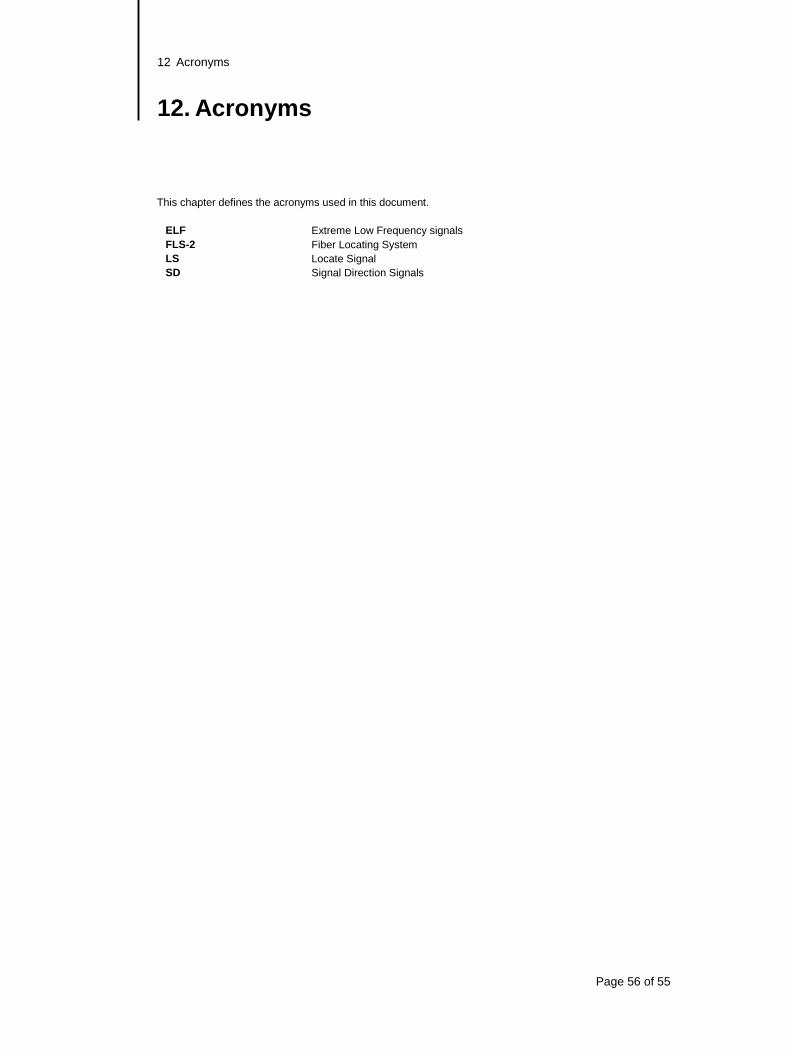
12 Acronyms
Page 56 of 55
12. Acronyms
This chapter defines the acronyms used in this document.
ELF Extreme Low Frequency signals
FLS-2 Fiber Locating System
LS Locate Signal
SD Signal Direction Signals
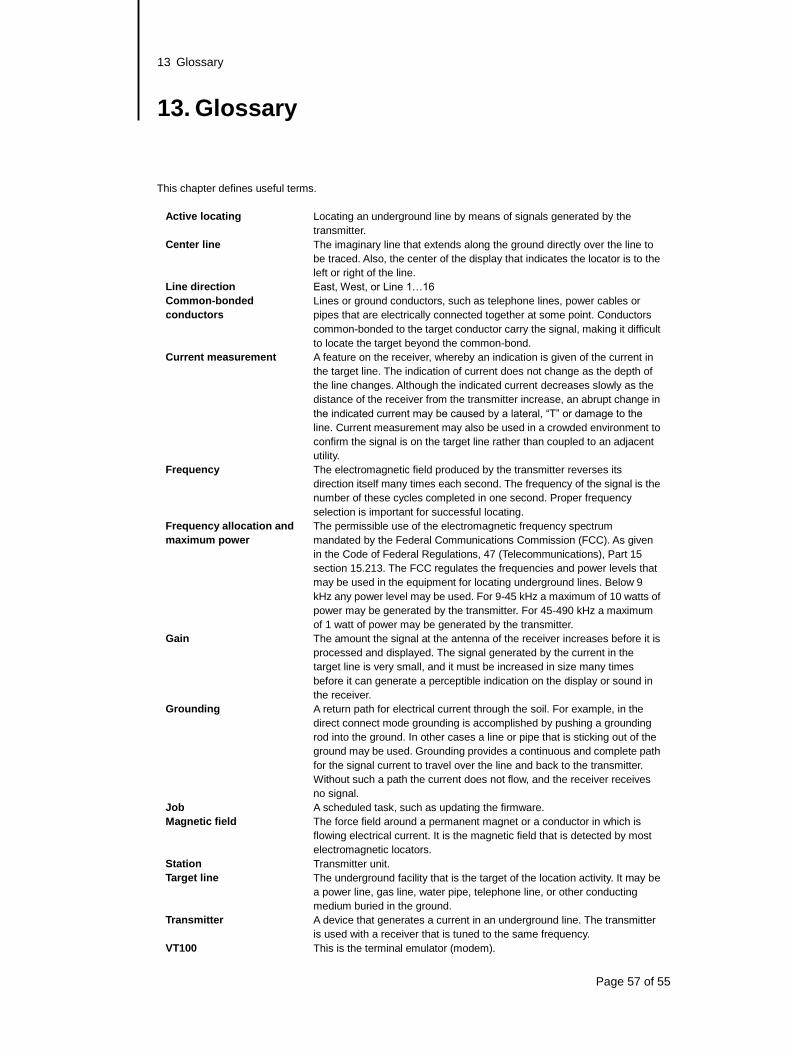
13 Glossary
Page 57 of 55
13. Glossary
This chapter defines useful terms.
Active locating Locating an underground line by means of signals generated by the
transmitter.
Center line The imaginary line that extends along the ground directly over the line to
be traced. Also, the center of the display that indicates the locator is to the
left or right of the line.
Line direction East, West, or Line 1…16
Common-bonded
conductors
Lines or ground conductors, such as telephone lines, power cables or
pipes that are electrically connected together at some point. Conductors
common-bonded to the target conductor carry the signal, making it difficult
to locate the target beyond the common-bond.
Current measurement A feature on the receiver, whereby an indication is given of the current in
the target line. The indication of current does not change as the depth of
the line changes. Although the indicated current decreases slowly as the
distance of the receiver from the transmitter increase, an abrupt change in
the indicated current may be caused by a lateral, “T” or damage to the
line. Current measurement may also be used in a crowded environment to
confirm the signal is on the target line rather than coupled to an adjacent
utility.
Frequency The electromagnetic field produced by the transmitter reverses its
direction itself many times each second. The frequency of the signal is the
number of these cycles completed in one second. Proper frequency
selection is important for successful locating.
Frequency allocation and
maximum power
The permissible use of the electromagnetic frequency spectrum
mandated by the Federal Communications Commission (FCC). As given
in the Code of Federal Regulations, 47 (Telecommunications), Part 15
section 15.213. The FCC regulates the frequencies and power levels that
may be used in the equipment for locating underground lines. Below 9
kHz any power level may be used. For 9-45 kHz a maximum of 10 watts of
power may be generated by the transmitter. For 45-490 kHz a maximum
of 1 watt of power may be generated by the transmitter.
Gain The amount the signal at the antenna of the receiver increases before it is
processed and displayed. The signal generated by the current in the
target line is very small, and it must be increased in size many times
before it can generate a perceptible indication on the display or sound in
the receiver.
Grounding A return path for electrical current through the soil. For example, in the
direct connect mode grounding is accomplished by pushing a grounding
rod into the ground. In other cases a line or pipe that is sticking out of the
ground may be used. Grounding provides a continuous and complete path
for the signal current to travel over the line and back to the transmitter.
Without such a path the current does not flow, and the receiver receives
no signal.
Job A scheduled task, such as updating the firmware.
Magnetic field The force field around a permanent magnet or a conductor in which is
flowing electrical current. It is the magnetic field that is detected by most
electromagnetic locators.
Station Transmitter unit.
Target line The underground facility that is the target of the location activity. It may be
a power line, gas line, water pipe, telephone line, or other conducting
medium buried in the ground.
Transmitter A device that generates a current in an underground line. The transmitter
is used with a receiver that is tuned to the same frequency.
VT100 This is the terminal emulator (modem).
13 Glossary
Page 58 of 55
Illustrations used in the preparation of this manual will inevitably show some resemblance to similar
illustrations from other Manufacturers-some manufacturers have given permision for the use of their graphics
(Vivax-Metrotech & Seba) other manufacturers such as Radiodetection request credit for their use. This
statement is intended to attribute such credit.
Disclaimer: All product availability or product accessory information is subject to change without notice.

Notes: ______________________________________________________________________________________
______________________________________________________________________________________
______________________________________________________________________________________
______________________________________________________________________________________
______________________________________________________________________________________
______________________________________________________________________________________
______________________________________________________________________________________
______________________________________________________________________________________
______________________________________________________________________________________
______________________________________________________________________________________
______________________________________________________________________________________
______________________________________________________________________________________
______________________________________________________________________________________
______________________________________________________________________________________
______________________________________________________________________________________
______________________________________________________________________________________
______________________________________________________________________________________
______________________________________________________________________________________
______________________________________________________________________________________
______________________________________________________________________________________
______________________________________________________________________________________
______________________________________________________________________________________
______________________________________________________________________________________
______________________________________________________________________________________
______________________________________________________________________________________
______________________________________________________________________________________
______________________________________________________________________________________