Fei Bao EF 2000 Typhoon - FBjets · Fei Bao EF 2000 Typhoon ... I used plastic clips to keep all...
29
Fei Bao EF 2000 Typhoon Developed and written by Luke Cullen The following instructions are developed based on a Kingtech K140 turbine, Spektrum powerbox, and Spektrum and JR radio. Think of the build as working from the back to the front which makes it seem easier. Every step focuses on easy maintenance when the need arises.
Transcript of Fei Bao EF 2000 Typhoon - FBjets · Fei Bao EF 2000 Typhoon ... I used plastic clips to keep all...

Fei Bao EF 2000 Typhoon
Developed and written by Luke Cullen
The following instructions are developed based on a Kingtech K140 turbine, Spektrum powerbox, and Spektrum and JR radio. Think of the build as working from the back to the front which makes it seem easier. Every step focuses on easy maintenance when the need arises.
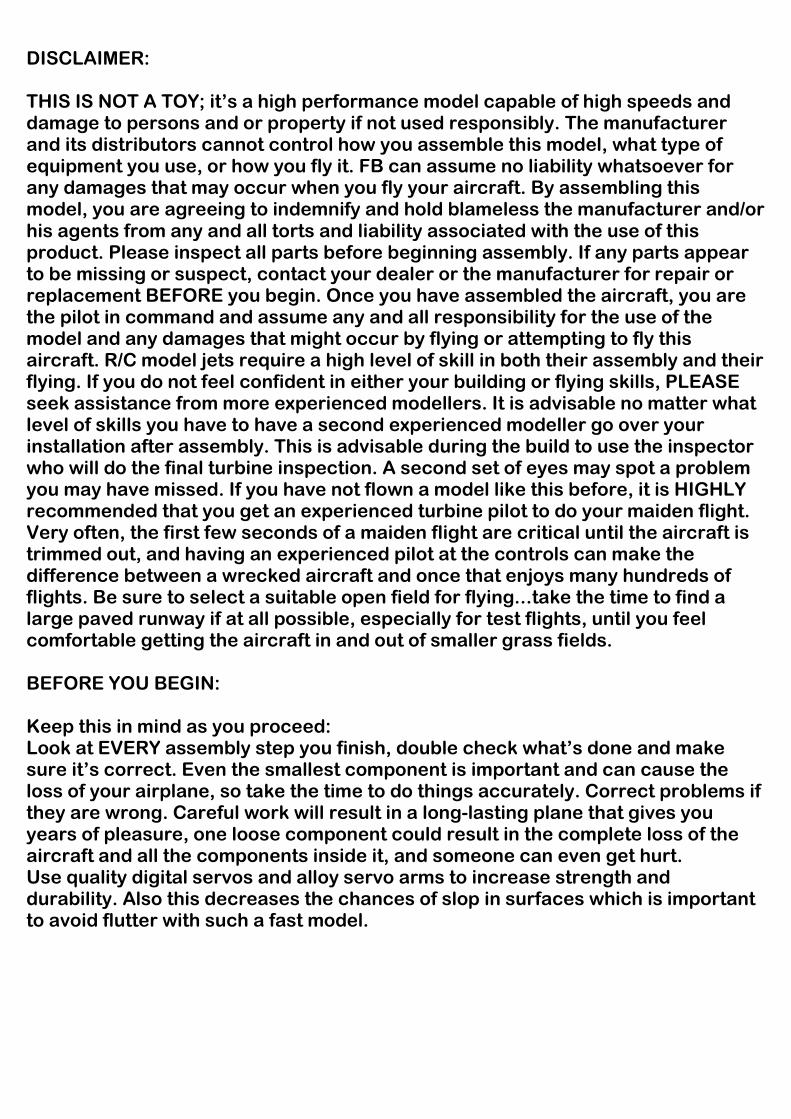
DISCLAIMER: THIS IS NOT A TOY; it’s a high performance model capable of high speeds and damage to persons and or property if not used responsibly. The manufacturer and its distributors cannot control how you assemble this model, what type of equipment you use, or how you fly it. FB can assume no liability whatsoever for any damages that may occur when you fly your aircraft. By assembling this model, you are agreeing to indemnify and hold blameless the manufacturer and/or his agents from any and all torts and liability associated with the use of this product. Please inspect all parts before beginning assembly. If any parts appear to be missing or suspect, contact your dealer or the manufacturer for repair or replacement BEFORE you begin. Once you have assembled the aircraft, you are the pilot in command and assume any and all responsibility for the use of the model and any damages that might occur by flying or attempting to fly this aircraft. R/C model jets require a high level of skill in both their assembly and their flying. If you do not feel confident in either your building or flying skills, PLEASE seek assistance from more experienced modellers. It is advisable no matter what level of skills you have to have a second experienced modeller go over your installation after assembly. This is advisable during the build to use the inspector who will do the final turbine inspection. A second set of eyes may spot a problem you may have missed. If you have not flown a model like this before, it is HIGHLY recommended that you get an experienced turbine pilot to do your maiden flight. Very often, the first few seconds of a maiden flight are critical until the aircraft is trimmed out, and having an experienced pilot at the controls can make the difference between a wrecked aircraft and once that enjoys many hundreds of flights. Be sure to select a suitable open field for flying...take the time to find a large paved runway if at all possible, especially for test flights, until you feel comfortable getting the aircraft in and out of smaller grass fields. BEFORE YOU BEGIN: Keep this in mind as you proceed: Look at EVERY assembly step you finish, double check what’s done and make sure it’s correct. Even the smallest component is important and can cause the loss of your airplane, so take the time to do things accurately. Correct problems if they are wrong. Careful work will result in a long-lasting plane that gives you years of pleasure, one loose component could result in the complete loss of the aircraft and all the components inside it, and someone can even get hurt. Use quality digital servos and alloy servo arms to increase strength and durability. Also this decreases the chances of slop in surfaces which is important to avoid flutter with such a fast model.

The FB EF2000 as it comes from the factory includes the following parts: Accessories included:Accessories included:Accessories included:Accessories included: 1 x Stainless steel double walled bifurcated thrust tube 2 x wooden engine mount spacers for Jet cat engines 2 x large 1.3 litre saddle fuel tanks with plumbing hardware 1 x large 2.4 litre fuel tank with all plumbing hardware 3 x coils of coloured plastic airline 1 x brake valve 1 x retract valve 1 x bag of air Y connectors 1 x bag of 4 way air connectors 1 x bag of fuel Y connectors 1 x bag of fuel plugs 7 x servo linkages 2 x small air tanks 2 x large air tanks 1 x bag of servo mounts and hardware 1 bag of steering cable parts including wire and crimps Multiple named bags with socket headed mounting bolts Airframe parts included Fuselage section Detachable nose section 2 x detailed cockpits 1 x rudder and fin 2 x canards 2 wing panels Canopy and removable hatch Ducting for the turbine intakes Plywood formers and trays Ordinance for the wings and fuselage Control horns
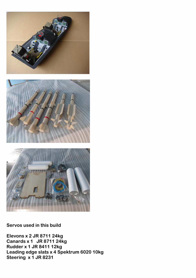
Servos used in this build Elevons x 2 JR 8711 24kg Canards x 1 JR 8711 24kg Rudder x 1 JR 8411 12kg Leading edge slats x 4 Spektrum 6020 10kg Steering x 1 JR 8231

I have used SWB alloy arms for all of the flying surfaces to increase the integrity of all the controls. They are 25mm arms which is ample for the amount of movement you need. I have tried to arrange a construction sequence that will allow you to keep moving forward, rather than standing around waiting for glue to dry before you can proceed to the next steps Introduction: You have chosen a model that represents the pinnacle of ARF technology. While there is not a lot of building to do, there is enough to keep you busy for a many hours. Even if you have assembled other ARF jets, we highly recommend following our assembly sequence and procedures anyway. Chances are it will save you a lot of time, prevent you from running down dead ends, and perhaps remind you of a few small things that might end up saving your aircraft. Just because the model is almost completely built does not mean you can rush through the assembly. You need to employ fine craftsmanship every step of the way, turbine models need critical care and attention. Keep this in mind with everything you do, every part you install...look at the work you just did, evaluate it critically, and ask yourself "is this going to potentially crash my airplane?" If there is any doubt about the work you have done, back up, and re-do it properly. Adhesives: The correct adhesive to use for all procedures is Loctite Hysol 9462. This is a very strong white epoxy that is thixotropic. "Thixotropic" means it does not run at all, but stays only where you put it. It is infinitely superior to regular epoxy, even slow-setting epoxy, for our purposes, because of this characteristic. Regular epoxy will run downhill with gravity as it dries, taking it away from where it is intended to be. A good example is in the hinges...using regular epoxy, a good portion of the glue will migrate down away from the hinge into the inside of the wing as it dries, and you won't even know it is happening. Hysol stays where you put it. The downside of Hysol is it takes overnight to dry properly, but I have tried to arrange things to keep you busy while waiting for glue to dry. I also highly recommend that you only use a proper Hysol dispensing gun with the long-type mixing nozzles. The short nozzles do not mix this glue enough and only a thin nozzle and gun will let you fill the hinge and control horn holes properly with glue, you can't do it mixing your Hysol on a flat surface and trying to get the glue in the proper place by a brush or stick. You can buy a complete Hysol setup including a mixing gun, nozzles and cartridges of glue from your local hobby supplier. Consider it a great investment, the glue is the best you will use. Two cartridges will be plenty to assemble your EF2000
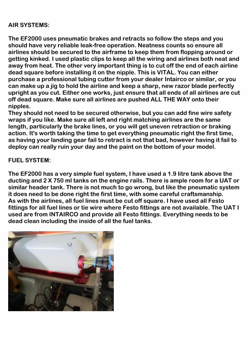
AIR SYSTEMS: The EF2000 uses pneumatic brakes and retracts so follow the steps and you should have very reliable leak-free operation. Neatness counts so ensure all airlines should be secured to the airframe to keep them from flopping around or getting kinked. I used plastic clips to keep all the wiring and airlines both neat and away from heat. The other very important thing is to cut off the end of each airline dead square before installing it on the nipple. This is VITAL. You can either purchase a professional tubing cutter from your dealer Intairco or similar, or you can make up a jig to hold the airline and keep a sharp, new razor blade perfectly upright as you cut. Either one works, just ensure that all ends of all airlines are cut off dead square. Make sure all airlines are pushed ALL THE WAY onto their nipples. They should not need to be secured otherwise, but you can add fine wire safety wraps if you like. Make sure all left and right matching airlines are the same length, particularly the brake lines, or you will get uneven retraction or braking action. It's worth taking the time to get everything pneumatic right the first time, as having your landing gear fail to retract is not that bad, however having it fail to deploy can really ruin your day and the paint on the bottom of your model. FUEL SYSTEM: The EF2000 has a very simple fuel system, I have used a 1.9 litre tank above the ducting and 2 X 750 ml tanks on the engine rails. There is ample room for a UAT or similar header tank. There is not much to go wrong, but like the pneumatic system it does need to be done right the first time, with some careful craftsmanship. As with the airlines, all fuel lines must be cut off square. I have used all Festo fittings for all fuel lines or tie wire where Festo fittings are not available. The UAT I used are from INTAIRCO and provide all Festo fittings. Everything needs to be dead clean including the inside of all the fuel tanks.

Rudder:Rudder:Rudder:Rudder:
The rudder servo mounts inside the fin and is secured by 4 screws.
Rough up the rudder horns and check the depth where they sit on the rudder. Check the positioning as the hole in the horn should be directly over the hinge point. Hysol the control horns to the rudder. Hysol tips work well getting glue in the hinge holes too.
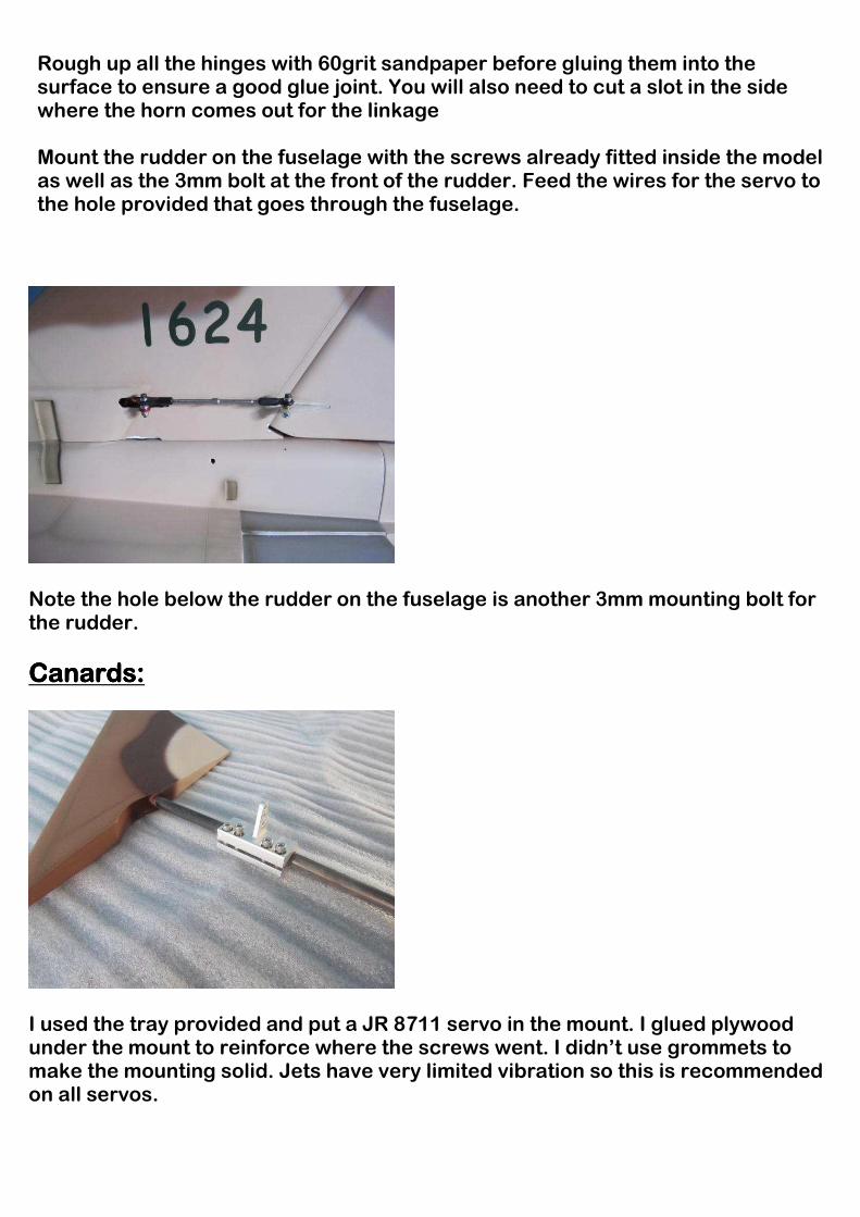
Rough up all the hinges with 60grit sandpaper before gluing them into the surface to ensure a good glue joint. You will also need to cut a slot in the side where the horn comes out for the linkage
Mount the rudder on the fuselage with the screws already fitted inside the model as well as the 3mm bolt at the front of the rudder. Feed the wires for the servo to the hole provided that goes through the fuselage.
Note the hole below the rudder on the fuselage is another 3mm mounting bolt for the rudder.
Canards:Canards:Canards:Canards:
I used the tray provided and put a JR 8711 servo in the mount. I glued plywood under the mount to reinforce where the screws went. I didn’t use grommets to make the mounting solid. Jets have very limited vibration so this is recommended on all servos.
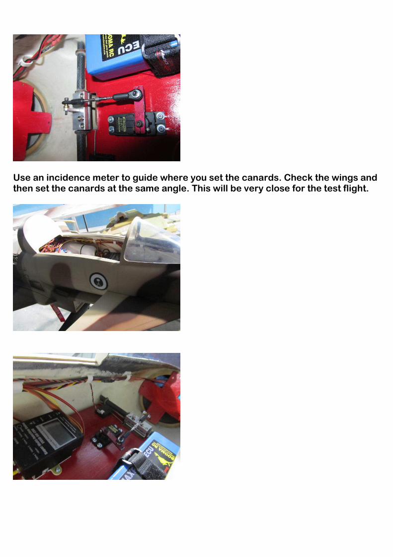
Use an incidence meter to guide where you set the canards. Check the wings and then set the canards at the same angle. This will be very close for the test flight.
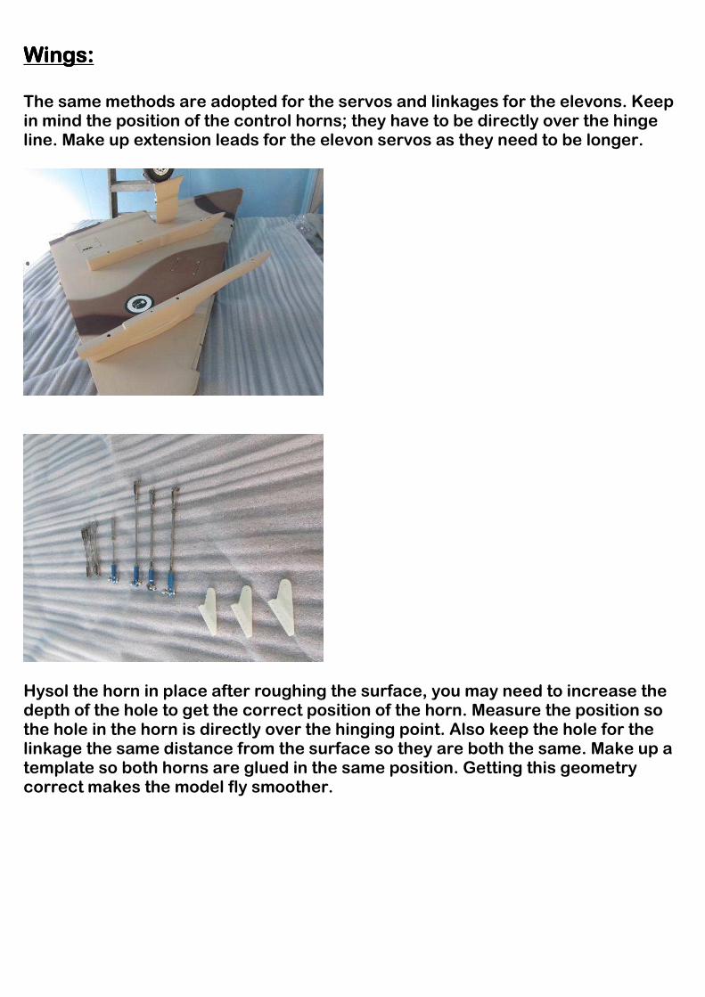
Wings:Wings:Wings:Wings: The same methods are adopted for the servos and linkages for the elevons. Keep in mind the position of the control horns; they have to be directly over the hinge line. Make up extension leads for the elevon servos as they need to be longer.
Hysol the horn in place after roughing the surface, you may need to increase the depth of the hole to get the correct position of the horn. Measure the position so the hole in the horn is directly over the hinging point. Also keep the hole for the linkage the same distance from the surface so they are both the same. Make up a template so both horns are glued in the same position. Getting this geometry correct makes the model fly smoother.
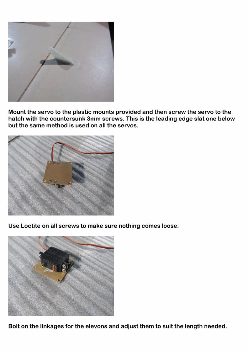
Mount the servo to the plastic mounts provided and then screw the servo to the hatch with the countersunk 3mm screws. This is the leading edge slat one below but the same method is used on all the servos.
Use Loctite on all screws to make sure nothing comes loose.
Bolt on the linkages for the elevons and adjust them to suit the length needed.

Mount the servos for the leading edge slats, I used Spektrum 6020 12 kg servos.
Use the same method to mount the servos with the plastic mounts provided. I used heavy duty nylon servo arms and cut them off short. The room is limited in this area so trial fit everything. I adjusted all 4 servos using the Powerbox Spektrum Cockpit.
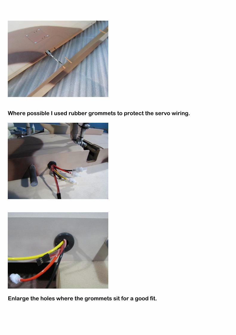
Where possible I used rubber grommets to protect the servo wiring.
Enlarge the holes where the grommets sit for a good fit.

Screw the covers provided to the wings to cover the servo arms and linkage. The end where the surface moves will need to be cut and made a separate piece.
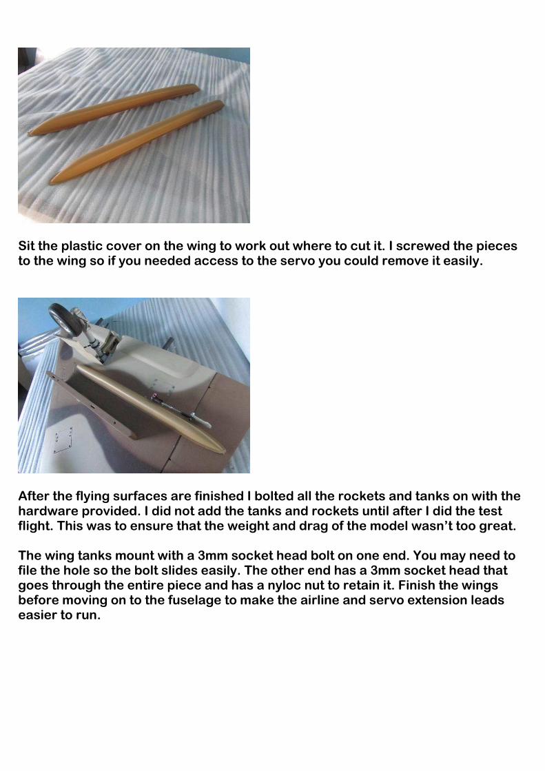
Sit the plastic cover on the wing to work out where to cut it. I screwed the pieces to the wing so if you needed access to the servo you could remove it easily.
After the flying surfaces are finished I bolted all the rockets and tanks on with the hardware provided. I did not add the tanks and rockets until after I did the test flight. This was to ensure that the weight and drag of the model wasn’t too great. The wing tanks mount with a 3mm socket head bolt on one end. You may need to file the hole so the bolt slides easily. The other end has a 3mm socket head that goes through the entire piece and has a nyloc nut to retain it. Finish the wings before moving on to the fuselage to make the airline and servo extension leads easier to run.
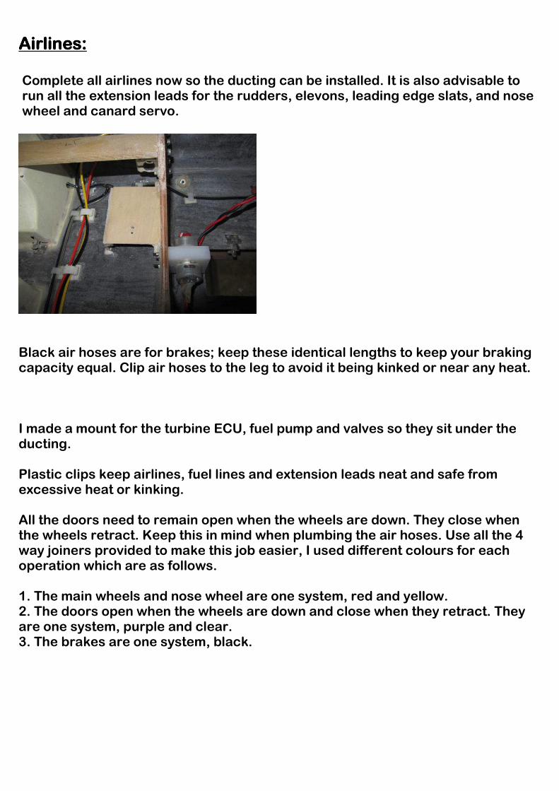
Airlines:Airlines:Airlines:Airlines: Complete all airlines now so the ducting can be installed. It is also advisable to run all the extension leads for the rudders, elevons, leading edge slats, and nose wheel and canard servo.
Black air hoses are for brakes; keep these identical lengths to keep your braking capacity equal. Clip air hoses to the leg to avoid it being kinked or near any heat. I made a mount for the turbine ECU, fuel pump and valves so they sit under the ducting. Plastic clips keep airlines, fuel lines and extension leads neat and safe from excessive heat or kinking. All the doors need to remain open when the wheels are down. They close when the wheels retract. Keep this in mind when plumbing the air hoses. Use all the 4 way joiners provided to make this job easier, I used different colours for each operation which are as follows. 1. The main wheels and nose wheel are one system, red and yellow. 2. The doors open when the wheels are down and close when they retract. They are one system, purple and clear. 3. The brakes are one system, black.
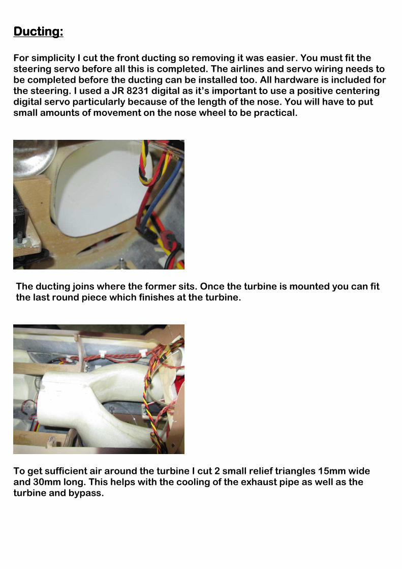
Ducting:Ducting:Ducting:Ducting: For simplicity I cut the front ducting so removing it was easier. You must fit the steering servo before all this is completed. The airlines and servo wiring needs to be completed before the ducting can be installed too. All hardware is included for the steering. I used a JR 8231 digital as it’s important to use a positive centering digital servo particularly because of the length of the nose. You will have to put small amounts of movement on the nose wheel to be practical.
The ducting joins where the former sits. Once the turbine is mounted you can fit the last round piece which finishes at the turbine.
To get sufficient air around the turbine I cut 2 small relief triangles 15mm wide and 30mm long. This helps with the cooling of the exhaust pipe as well as the turbine and bypass.
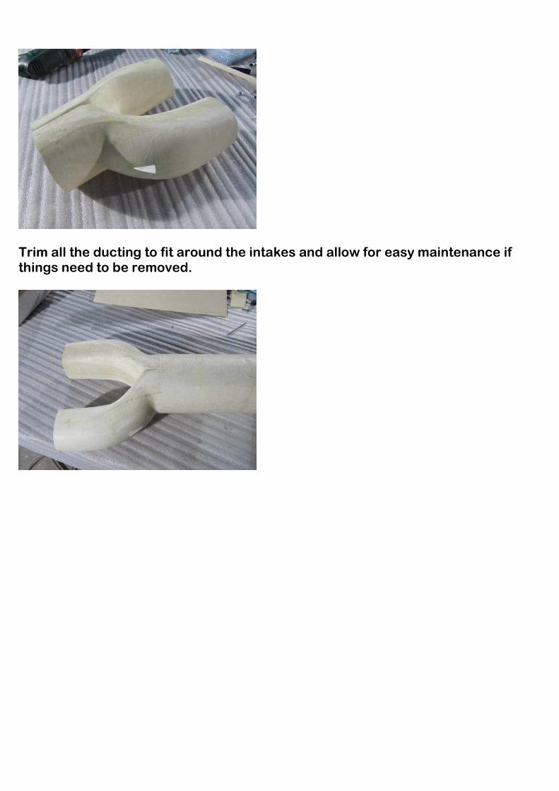
Trim all the ducting to fit around the intakes and allow for easy maintenance if things need to be removed.
TTTTailpipesailpipesailpipesailpipes:
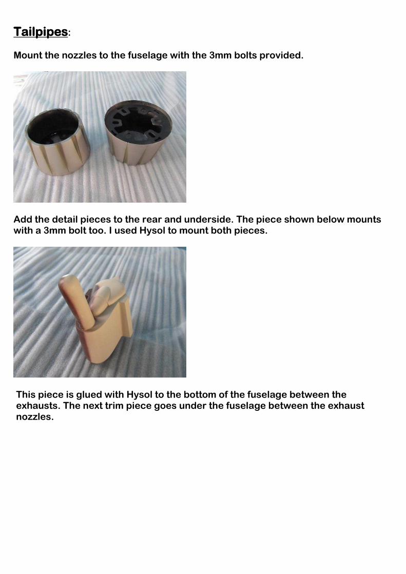
Mount the nozzles to the fuselage with the 3mm bolts provided.
Add the detail pieces to the rear and underside. The piece shown below mounts with a 3mm bolt too. I used Hysol to mount both pieces.
This piece is glued with Hysol to the bottom of the fuselage between the exhausts. The next trim piece goes under the fuselage between the exhaust nozzles.
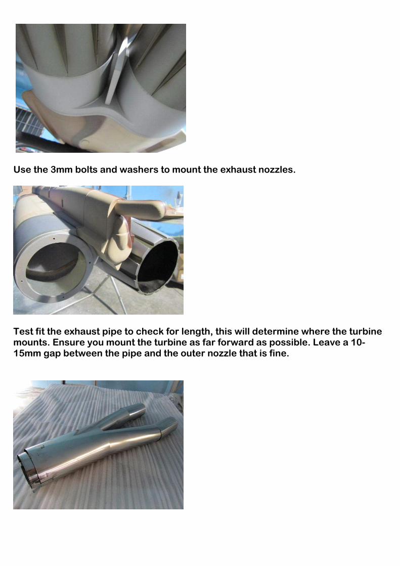
Use the 3mm bolts and washers to mount the exhaust nozzles.
Test fit the exhaust pipe to check for length, this will determine where the turbine mounts. Ensure you mount the turbine as far forward as possible. Leave a 10-15mm gap between the pipe and the outer nozzle that is fine.
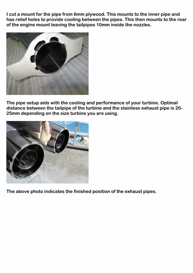
I cut a mount for the pipe from 6mm plywood. This mounts to the inner pipe and has relief holes to provide cooling between the pipes. This then mounts to the rear of the engine mount leaving the tailpipes 10mm inside the nozzles.
The pipe setup aids with the cooling and performance of your turbine. Optimal distance between the tailpipe of the turbine and the stainless exhaust pipe is 20-25mm depending on the size turbine you are using.
The above photo indicates the finished position of the exhaust pipes.

Mount the pipe bracket to the engine rails with the bolt already there. I also mounted the bypass to the rails as well. This keeps the entire set up mounted solidly.
Test fit the turbine and fit blind nuts under the rails. Also use the countersunk screws so they are flush. I put all the 3mm screws in the wing mounts before installing the turbine. This is advisable as access is much easier before the turbine is mounted.
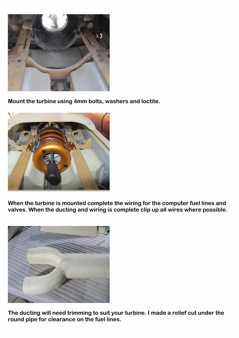
Mount the turbine using 4mm bolts, washers and loctite.
When the turbine is mounted complete the wiring for the computer fuel lines and valves. When the ducting and wiring is complete clip up all wires where possible.
The ducting will need trimming to suit your turbine. I made a relief cut under the round pipe for clearance on the fuel lines.
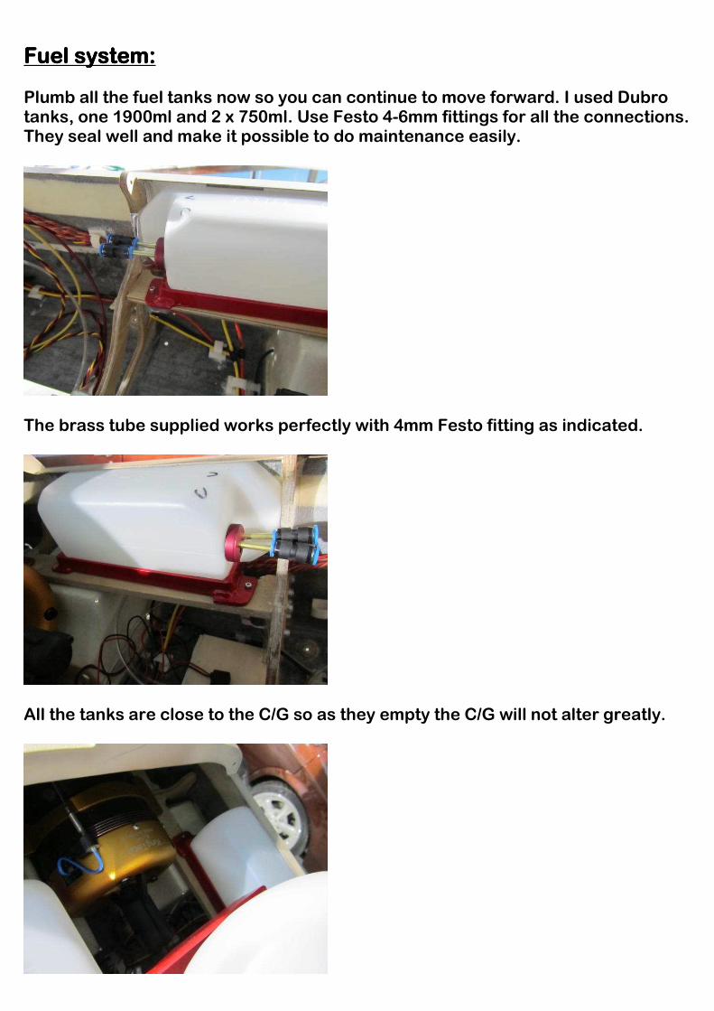
Fuel systemFuel systemFuel systemFuel system:::: Plumb all the fuel tanks now so you can continue to move forward. I used Dubro tanks, one 1900ml and 2 x 750ml. Use Festo 4-6mm fittings for all the connections. They seal well and make it possible to do maintenance easily.
The brass tube supplied works perfectly with 4mm Festo fitting as indicated.
All the tanks are close to the C/G so as they empty the C/G will not alter greatly.
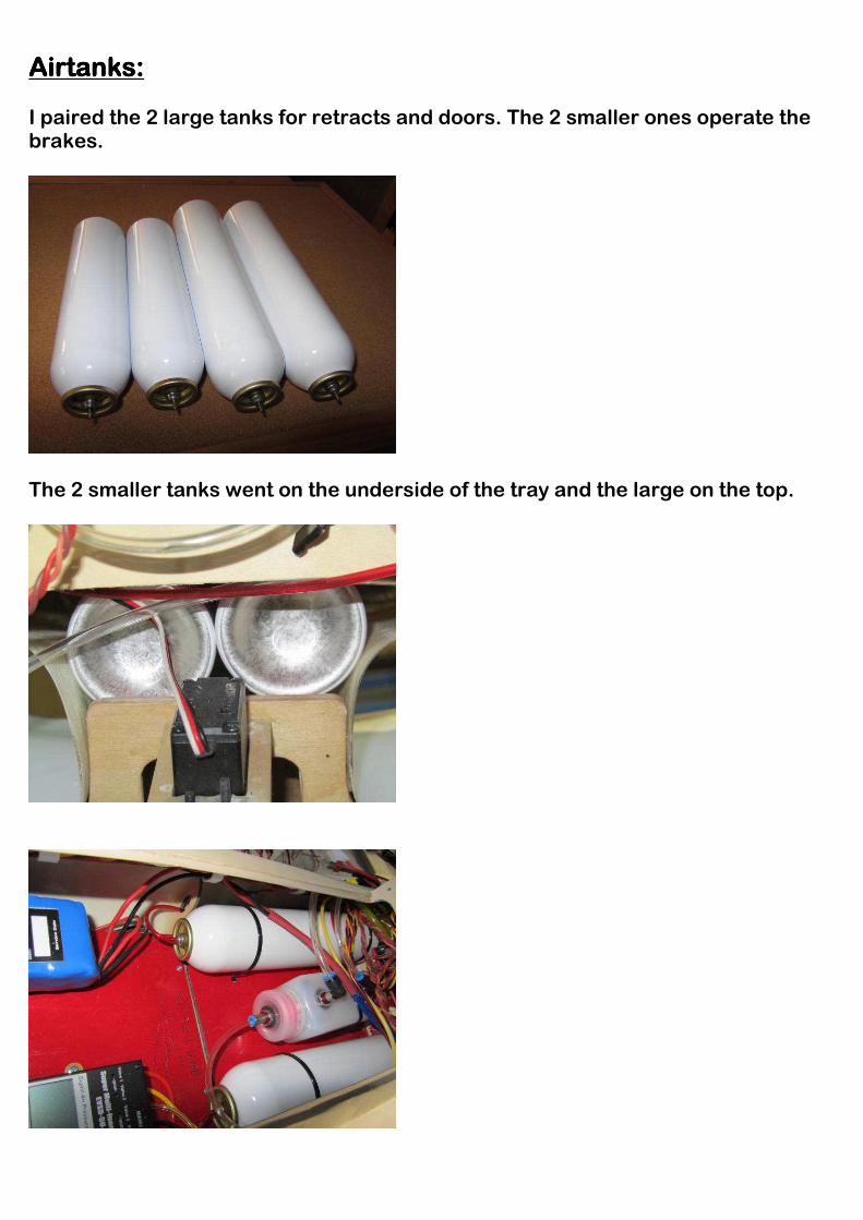
Airtanks:Airtanks:Airtanks:Airtanks:
I paired the 2 large tanks for retracts and doors. The 2 smaller ones operate the brakes.
The 2 smaller tanks went on the underside of the tray and the large on the top.

The EF2000 has a factory installed removable nose section which makes mounting the batteries very simple. I made a removable tray for both the batteries for the flight system.
Mount the nosecone with the 4 x 3mm bolts using Loctite on them.
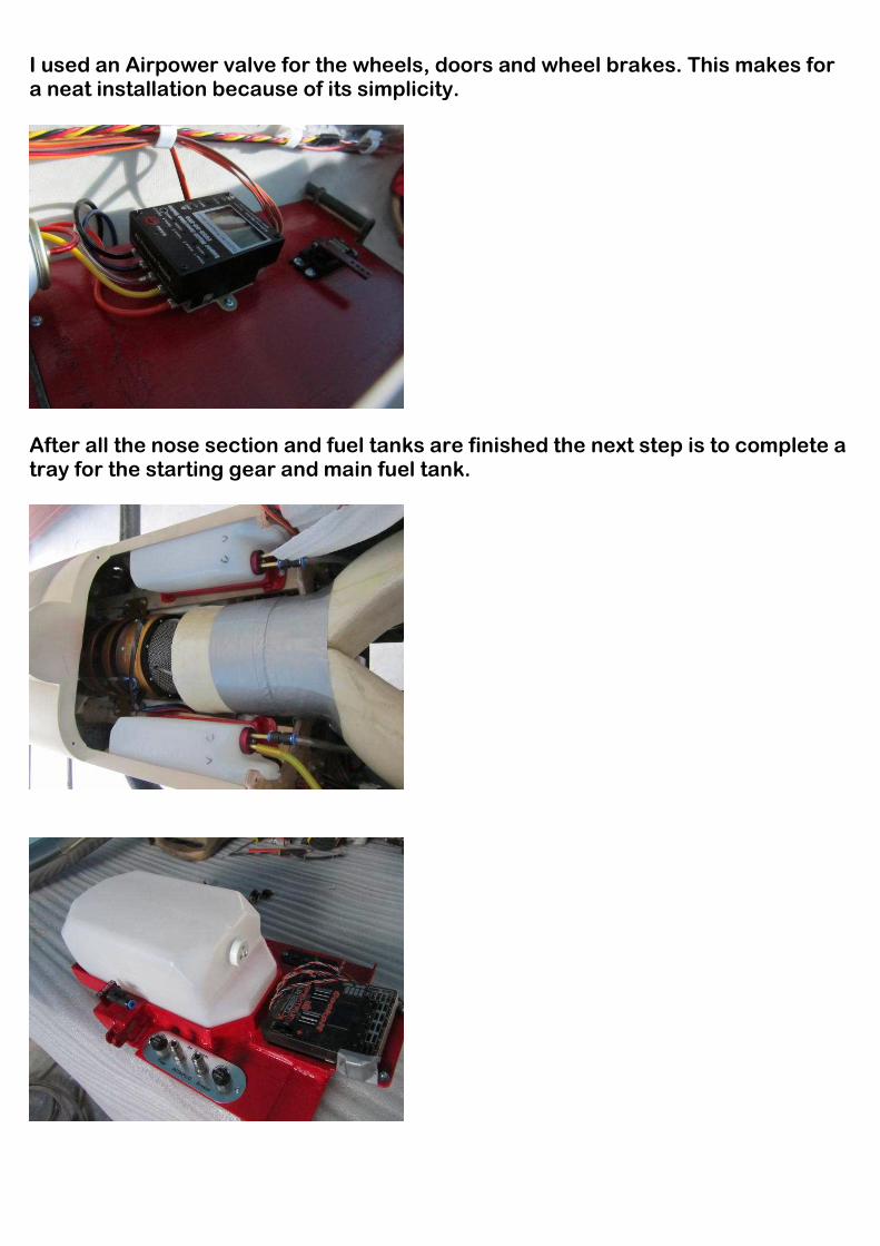
I used an Airpower valve for the wheels, doors and wheel brakes. This makes for a neat installation because of its simplicity.
After all the nose section and fuel tanks are finished the next step is to complete a tray for the starting gear and main fuel tank.
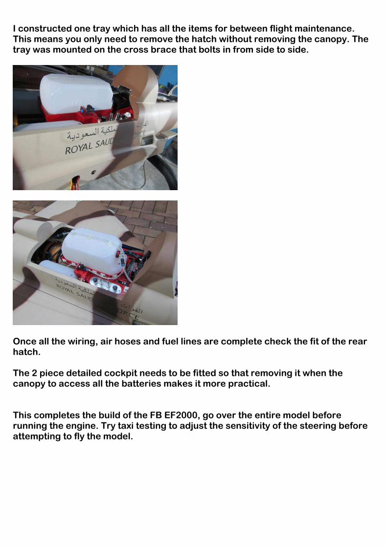
I constructed one tray which has all the items for between flight maintenance. This means you only need to remove the hatch without removing the canopy. The tray was mounted on the cross brace that bolts in from side to side.
Once all the wiring, air hoses and fuel lines are complete check the fit of the rear hatch. The 2 piece detailed cockpit needs to be fitted so that removing it when the canopy to access all the batteries makes it more practical. This completes the build of the FB EF2000, go over the entire model before running the engine. Try taxi testing to adjust the sensitivity of the steering before attempting to fly the model.

EF2000EF2000EF2000EF2000 control throws and C/G control throws and C/G control throws and C/G control throws and C/G Elevator 35mm up and down, 20% expo Ailerons 25mm up and down, 20% expo Canards 20mm up and down, 25% expo Rudder 30mm left and right, 20% expo Nose wheel servo, 10-15 degrees movement with 15-20% expo C/G 330mm from leading edge at the root of the left wing with the UAT’s full of fuel. Suggested engine sizes are 10-14 kilo thrust turbine. My model weighed 15.8 kilos dry when complete. Good luck and now enjoy this amazing model jet from Fei Bao.