FDM 11-25 Intersections at Grade
83
Page 1 Facilities Development Manual Wisconsin Department of Transportation Chapter 11 Design Section 25 Intersections at Grade FDM 11-25-1 General March 31, 2017 1.1 Design Consideration Design an intersection to either rural or urban design criteria depending on its location and the type of existing or planned development in the area. Design intersections located to serve a present or future residential or commercial area to urban standards with specific consideration of the current or eventual need for a new or a change in intersection traffic control or type cross walks, pedestrian signals, expected traffic volumes, and size of vehicles expected. Consult with the region planning staff to determine the type of development planned in the area of the intersection. It is very important to include Traffic Operations personnel early in the scoping of a project to assist the design team with the traffic control, signage, and pavement marking analysis and decision-making. In addition, safety countermeasure decisions and the need for facilities that serve large trucks and oversized-overweight (OSOW) vehicles must also involve Traffic Operations personnel and the Regional Freight Coordinator. Try to keep the size of intersections to a minimum, including roundabouts. Designing intersections for large trucks requires large corner radii, which substantially increases the size of the intersection. Larger intersections generally have greater crash potential, are more difficult to delineate, may be more confusing for drivers and other users, require more right-of-way, and significantly increase pedestrian and bicycle crossing times and distances. References for this chapter include Chapter 9 of the AASHTO GDHS 1 and other sources as noted. Specific factors and features to consider are: - Safety - some factors that affect intersection safety include: - Number of approaches - Number of potential conflict points - Type of traffic control and advance signing (see FDM 11-25-3; also, see WisDOT's Traffic Engineering Operations and Safety Manual (TEOpS) and traffic signal design manual (TSDM) and consult with Traffic Operations) - Approach sight distance, i.e., the visibility of the intersection to an approaching driver (see FDM 11-10-5) - Intersection Sight distance (see FDM 11-10-5) - Intersection skew angle (see FDM 11-25-2.8) - Whether the intersection is located on a curve (see FDM 11-25-2.9) - Street lighting - Turn Lanes (see FDM 11-25-2.2 and 2.3; also see FDM 11-25-5 and FDM 11-25-10) - Auxiliary lanes (see FDM 11-25-35) - Access management (see FDM 11-25-2.5. FDM 11-25-20, FDM 11-5-5, FDM chapter 7 and HMM Chapter 91) - Intersection radii and channelization (see FDM 11-25-10 and FDM 11-25-25; also see SDD 9A1) - Functional classes of the intersecting roadways (see FDM 11-25 Table 2.1; also see FDM 11-15-1 Attachment); - Designated Long Truck Routes, 75' Restricted Truck Routes, 65' Restricted Truck routes and statewide Oversized-overweight Truck Route (OSOW-TR) (see FDM 11-25-1.4). - Topography and surrounding land uses - examples: - The length of the crossroad available for traffic generating development including potential extensions - In urban and suburban or transitional areas, there is the potential for development to occur along the highway or adjacent frontage roads. Traffic from this development will feed into the crossroad. 1 (1) A Policy on Geometric Design of Highways and Streets 2004, 5th edition. AASHTO, 2004.
Transcript of FDM 11-25 Intersections at Grade

Page 1
Facilities Development Manual Wisconsin Department of Transportation Chapter 11 Design Section 25 Intersections at Grade
FDM 11-25-1 General March 31, 2017
1.1 Design Consideration
Design an intersection to either rural or urban design criteria depending on its location and the type of existing or planned development in the area. Design intersections located to serve a present or future residential or commercial area to urban standards with specific consideration of the current or eventual need for a new or a change in intersection traffic control or type cross walks, pedestrian signals, expected traffic volumes, and size of vehicles expected. Consult with the region planning staff to determine the type of development planned in the area of the intersection.
It is very important to include Traffic Operations personnel early in the scoping of a project to assist the design team with the traffic control, signage, and pavement marking analysis and decision-making. In addition, safety countermeasure decisions and the need for facilities that serve large trucks and oversized-overweight (OSOW) vehicles must also involve Traffic Operations personnel and the Regional Freight Coordinator. Try to keep the size of intersections to a minimum, including roundabouts. Designing intersections for large trucks requires large corner radii, which substantially increases the size of the intersection. Larger intersections generally have greater crash potential, are more difficult to delineate, may be more confusing for drivers and other users, require more right-of-way, and significantly increase pedestrian and bicycle crossing times and distances.
References for this chapter include Chapter 9 of the AASHTO GDHS1 and other sources as noted.
Specific factors and features to consider are:
- Safety - some factors that affect intersection safety include:
- Number of approaches
- Number of potential conflict points
- Type of traffic control and advance signing (see FDM 11-25-3; also, see WisDOT's Traffic Engineering Operations and Safety Manual (TEOpS) and traffic signal design manual (TSDM) and consult with Traffic Operations)
- Approach sight distance, i.e., the visibility of the intersection to an approaching driver (see FDM 11-10-5)
- Intersection Sight distance (see FDM 11-10-5)
- Intersection skew angle (see FDM 11-25-2.8)
- Whether the intersection is located on a curve (see FDM 11-25-2.9)
- Street lighting
- Turn Lanes (see FDM 11-25-2.2 and 2.3; also see FDM 11-25-5 and FDM 11-25-10)
- Auxiliary lanes (see FDM 11-25-35)
- Access management (see FDM 11-25-2.5. FDM 11-25-20, FDM 11-5-5, FDM chapter 7 and HMM Chapter 91)
- Intersection radii and channelization (see FDM 11-25-10 and FDM 11-25-25; also see SDD 9A1)
- Functional classes of the intersecting roadways (see FDM 11-25 Table 2.1; also see FDM 11-15-1 Attachment);
- Designated Long Truck Routes, 75' Restricted Truck Routes, 65' Restricted Truck routes and statewide Oversized-overweight Truck Route (OSOW-TR) (see FDM 11-25-1.4).
- Topography and surrounding land uses - examples:
- The length of the crossroad available for traffic generating development including potential extensions
- In urban and suburban or transitional areas, there is the potential for development to occur along the highway or adjacent frontage roads. Traffic from this development will feed into the crossroad.
1 (1) A Policy on Geometric Design of Highways and Streets 2004, 5th edition. AASHTO, 2004.

FDM 11-25 Intersections at Grade
Page 2
- Commercial or industrial zoned areas may attract truck terminals or other truck generators.
- Schools, parks, residential developments are examples of destinations that should anticipate bicycle, pedestrian and transit increases as well as motor vehicles.
- Corridor Considerations
- The appropriate design and traffic control of an individual intersection must provide a safe environment with adequate capacity, and also reflect the needs of adjacent intersections and the corridor as a whole. As such, isolated intersection designs may benefit from features not dictated by capacity alone. These features should be consistent with the overall facility, examples of which may include: turn lanes, separation of turn lanes from adjacent through lanes, raised medians, islands, and on-road bicycle accommodations. Right-of-way may also need to be preserved for future corridor-based improvements.
- Regulatory speed limits are rarely reduced just for intersections. Guidance on “Speed Limits” is provided in the TGM 13-5-5 (http://wisconsindot.gov/Pages/doing-bus/local-gov/traffic-ops/manuals-and-standards/tgm/tgm.aspx). If a speed reduction is desired for an intersection, work with Region Traffic staff, as they are responsible for any speed limit changes. Also by statutory authority (ss 346.57 and 349.11), speed zone declarations are required when the traffic on a STH is required to reduce speed as a result of a regulatory speed limit sign installation. The development of a declaration needs to be based on an engineering study coordinated with Region Traffic staff.
- Traffic characteristics:
- Current and expected daily traffic volumes and turning movements (see FDM 3-10-10)
- Current and expected Design hour volumes and turning movements (see FDM 3-10-10)
- Composition of traffic - including trucks and buses (and bicycles) (see FDM 3-10-10)
- OSOW vehicles - including on roads that are not currently on the OSOW Truck Route (OSOW-TR), but which contain an OSOW origination point, or a recurring OSOW destination (e.g., a manufacturing plant or a gravel pit) (see FDM 11-25-1.4 and FDM 11-25-2.1.1).
- Design vehicle (see FDM 11-25-2.1)
- Vehicle speeds
- Level of Service (see FDM 11-25-3 and FDM 11-5-3)
- Traffic Control Warrants and Design:
- See FDM 11-25-1.1.2
- Crash experience – including numbers, rates, locations, types, and severity
- Road user types - motorists, transit, bicyclists, and pedestrians
- Sidewalk approaches and crosswalks (see FDM 11-46-5 and FDM 11-46-10)
- Pedestrian crossing distance and Pedestrian Clearance Time
- Geometry and cross-sections of the approach roadways and the intersection;
- Drainage requirements (see FDM chapter 13)
- Proximity and traffic volumes of driveways and other roads (see FDM 11-25-2.5; also see FDM 11-5-5 and FDM 11-25-20; Refer to FDM 11-30-1 regarding ramp terminal spacing)
- Right-of-way requirements (see FDM 11-25-1.1.1)
- Cost and Potential impacts
1.1.1 Right-of-Way Considerations
Public right-of-way at STH intersections needs to accommodate design geometrics (for existing & future conditions), operations-related infrastructure, and adequate sight distance. All WisDOT maintained signal & electrical equipment must either be located within the public right-of-way or within a permanent limited easement (PLE). Such signal equipment typically includes cabinet bases, signal/lighting bases, vehicle detection, associated conductor runs, and possibly temporary signal support guy-lines. Place this equipment in locations where it is less likely to be struck by an errant vehicle - because this can reduce crash frequency and severity, as well as maintenance costs. Also, consider the placement of this equipment in relation to existing or future sidewalks or shared-use paths.
Also, consider future capacity expansion. Examples include right- and left-turn lanes, widened medians, sidewalk, bike lanes, and future intersection or interchange type. Because of these issues, involve Regional Traffic Engineering and Planning (e.g. bike/pedestrian coordinator, access management coordinator) staff in identifying required right-of-way at signalized intersections and interchanges early in the design process.

FDM 11-25 Intersections at Grade
Page 3
1.1.2 Traffic Control Warrants and Design - See FDM 11-25-3 for guidance on the engineering study that shall be used to assist in selecting the
appropriate type of intersection traffic control
- In general, terms, any intersection, urban or rural, that meets the criteria for a four-way stop condition or a traffic signal, also qualifies for evaluation as a modern roundabout. For more information on roundabouts, see FDM 11-26.
- Typically, any interchange that meets the criteria to evaluate a signalized diamond or roundabout, could also qualify for the evaluation of Reduced-Conflict Interchanges, given the traffic volumes and patterns. These interchange types include a Diverging Diamond Interchange (DDI) and a Single Point Interchange (SPI); see FDM 11-25-3.
- Consult with the region traffic section on the design and location of traffic signals. Applicable references include:
- FHWA Manual of Uniform Traffic Control Devices (MUTCD) at:
http://mutcd.fhwa.dot.gov/
- Wisconsin Supplement to the MUTCD (WMUTCD) at:
http://wisconsindot.gov/Pages/doing-bus/local-gov/traffic-ops/manuals-and-standards/wmutcd/wmutcd.aspx
- WisDOT’s Traffic Signal Design Manual (TSDM) at:
http://wisconsindot.gov/Pages/doing-bus/local-gov/traffic-ops/manuals-and-standards/tsdm/tsdm.aspx
- WisDOT’s Traffic Engineering Operations and Safety Manual (TGM) at:
http://wisconsindot.gov/Pages/doing-bus/local-gov/traffic-ops/manuals-and-standards/teops/default.aspx
- A specific traffic control or intersection type may not be immediately warranted on a project but may be warranted within the project‘s design life. See FDM 11-25-3 for guidance on Intersection Control Evaluation (ICE) studies.
1.1.2.1 Through Highway Declaration Process
As new or modified traffic control installations at intersections take place is important to follow the through highway declaration process. By statutory authority (ss 340.01(67) and 349.07), a yield sign (e.g. roundabout), stop sign, or signal installation on a STH or connecting highway requires an approval process. Guidance on “Through Highway Declarations” is provided in the TGM 13-1-1. Regardless of the type of traffic control proposed, associated “through highway declarations” need to be developed and are maintained by the Regional Traffic staff.
1.2 Urban Intersections
At-grade urban intersections consist of a variety of types that cannot be grouped by a class of highway. Factors that influence intersection design are peak-hour traffic volumes, type and size of turning vehicles, traffic control, turning roadways, auxiliary lanes, number of lanes, divided or undivided cross section, pedestrian traffic, and right of way limitations. The proximity of commercial and industrial sites may require special designs.
Intersection geometry and operations need to accommodate all roadway users - including pedestrians and bicyclists - and provide safe travel and crossing (see FDM 11-46 for guidance on bicycle and pedestrian accommodations). Minimize the size of the intersection and the pedestrian crossing distance by designing intersection radii as small as possible. If the design vehicle is larger than a Single Unit (SU truck or a bus), consider using a two-or three centered curve. Use templates or automated programs to determine the vehicle path and then develop a two-or three-centered curve that closely emulates this path. Look at a range of vehicle turning radii and select the best fit for the design vehicle while minimizing the size of the intersection. 2
A legal crosswalk exists at intersections, including “Tee” intersections, where the side road has sidewalks on one or both sides of the street and the through street has sidewalk on the opposite side of the street from the side road, whether the crosswalk is pavement marked or not3. FDM 11-46-10 further describes curb ramp installation requirements and other conditions when curb ramp installation may be desirable.
When possible, prohibit parking near the intersection on routes identified on the Long Truck Operators Map and the OSOW Truck Route to avoid conflicts with turning traffic. Large vehicles require greater turning radii and
2 ORDOT Highway Design Manual (2) ORDOT Highway Design Manual ch. 9.0: Intersection and Interchange Design. Oregon Department of Transportation, 2008. ftp://ftp.odot.state.or.us/techserv/roadway/web_drawings/HDM/Rev_E_2003Chp09.pdf, Ch. 9, pp.14-15, “Intersection and Interchange Design” 3 Per s.340.01 (10) (b), Wis. Stats.

FDM 11-25 Intersections at Grade
Page 4
wider sweeping paths to negotiate corners. Review whether parking, roadside utilities, or street furniture will impede long truck and OSOW movements. This is of particular concern at the intersection of multiple state trunk highways in established urban environments. Certain OSOW loads (such as a bridge girder) will encroach beyond the face of curb even when the transport axles stay within the street. Refer to FDM 11-20-1 for additional Parking Lane and Border guidance.
1.3 Rural Intersections
The At-Grade Side Road Intersections standard detail drawing (SDD 9A1-a and b) illustrate six types of rural at-grade intersection: A1, A2, B1, B2, C and D. This SDD applies to two-lane undivided and multilane divided high speed rural highways. The intersection type will indicate the length of a turn lane and shall apply to both the left turning and the right turning traffic entering the same side road leg. The lengths of the turn lanes are for deceleration only. If additional storage is needed to accommodate queuing Design Hour Traffic, or there is a high volume of truck turning movements, then provide a longer turn lane based on needed storage. Attachment 1.1 lists the criteria for using each type of intersection. FDM 11-25 Attachment 5.4 shows the median opening and non-slotted turn lanes on rural expressways.
Consider other roadways users such as pedestrian, bicyclists and transit users based on existing and future land uses. Even though these users are not typically as prevalent in rural and high speed settings as they are in urban settings, this may change with changing land uses. See FDM 11-46, “Complete Streets”, for guidance on pedestrian and bicycle accommodations. See FDM 11-25-35.3 for guidance on bus stops at intersections.
1.3.1 Intersections on Rural High-Speed Multilane Divided Highways (“Rural Expressways”)4
A rural high-speed (≥50 mph), multilane, divided highway with partial access control is typically referred to as a “rural expressway”5. Rural expressways are generally a hybrid design between a freeway and a conventional two-lane rural arterial roadway. Like freeways, rural expressways are typically four-lane divided facilities (i.e., two lanes in each direction separated by a wide, depressed, turf median), which may also have grade separations and interchanges. Like conventional two-lane undivided rural arterials, expressways have partial access control allowing at-grade intersections and limited driveway access with the potential for signalization (although signalization is typically discouraged). Expressways provide many of the mobility, travel efficiency, economic and safety benefits of freeways at a far lower cost. However, increased at-grade intersection crashes and increased intersection crash severity diminish the expected safety benefits of expressways.
The typical rural expressway intersection is an at-grade two-way stop controlled (TWSC) with the stop control on the minor (usually two-lane) roadway. Expressway interchanges are generally limited to locations that meet traffic volume warrants and/or that have a disproportionate rate of serious crashes, and/or to meet driver expectancy due to the functionality of the side road and where the additional expenditure can be justified.
TWSC rural expressway intersections often experience safety problems long before the design life of the facility and even before meeting traffic signal volume warrants. The percentage of total expressway crashes which occur at TWSC intersections increases as the mainline traffic volumes increase and that all intersection crashes increase and become more severe as minor roadway volumes increase. Right-angle collisions are the predominant crash type at conventional TWSC rural expressway intersections. The most problematic of these (with respect to severity) tend to be those occurring in the far-side intersection (i.e., after the minor road driver has traveled through the median). The underlying cause of these collisions in most cases is not failure to yield, but the inability of the driver stopped on the minor road approach to judge the arrival time of approaching expressway traffic (i.e., gap selection).
1.3.1.1 Rural Expressway Intersection Safety Treatments6
As illustrated in Figure 1.1a, the traditional approach to addressing safety problems at expressway intersections - after addressing potential design issues such as insufficient sight distance - is to improve the traffic-control devices, implement traffic signal control (if warranted), - and eventually construct an overpass or interchange. Traffic signals in rural areas are discouraged for several reasons including violation of driver expectations and difficulty in servicing and maintaining signals in remote locations. Signals also hamper the intended mobility of expressways. In addition, traffic signals do not always improve safety - they may only change the crash type 4 From Maze et al in NCHRP Report 650 (3) NCHRP Report 650: Median Intersection Design for Rural High-Speed Divided Highways. Transportation Research Board of the National Academies, 2010. http://onlinepubs.trb.org/onlinepubs/nchrp/nchrp_rpt_650.pdf, p.4, Background; p.147, Conclusions; pp. 1-3, Summary 5 Some roadways in Wisconsin are “designated expressways” per Wis Stat 84.295. The term “rural expressway” is used herein to describe a rural high-speed (≥50 mph), multilane, divided highway with partial access control, regardless of whether the roadway is “designated expressway”. 6 From Maze et al in NCHRP Report 650 (3) NCHRP Report 650: Median Intersection Design for Rural High-Speed Divided Highways. Transportation Research Board of the National Academies, 2010. http://onlinepubs.trb.org/onlinepubs/nchrp/nchrp_rpt_650.pdf., pp. 44-63)
FDM 11-25 Intersections at Grade
Page 5
distribution. The construction of an interchange reduces the cost advantage of building an expressway as compared with building a freeway, and the mix of at-grade intersections and interchanges tends to violate driver expectations.
However, as illustrated in Figure 1.1b, non-signalized safety countermeasures have been used more often in recent years. These safety treatments for rural expressway intersections fall into three broad categories:
1. Conflict-point management strategies,
2. Gap selection aids, and
3. Intersection recognition devices.
Table 1.1 provides a listing of safety treatments by category. In general, select the most appropriate safety countermeasure based on the crash types occurring at each location. The conflict-point management strategies and the gap selection aids seem to have the most potential to improve safety at rural expressway intersections because they address the apparent underlying cause of many crashes at TWSC rural expressway intersections (i.e., far-side gap selection by crossing and left-turning minor road drivers).

FDM 11-25 Intersections at Grade
Page 6
Table 1.1 Potential rural-expressway intersection safety treatment7
Category Subcategory No. Safety Treatment
Conflict Point Management
Strategies
Removal/ Reduction Through Access
Control
1. Conversion of entire expressway corridor to freeway
2. Isolated conversion to grade separation or interchange
3. Close low-volume minor road intersections and use frontage roads [See FDM 11-25-45]
4. Close median crossovers (right-in, right-out access only)
5. Convert four-legged intersection into T-intersection or initially construct T-intersections instead of four-legged intersections (Use a one-quadrant interchange [A] if necessary)
Replacement of High-Risk Conflict-points
1. J-turn intersections (indirect minor road crossing and left-turns) [A][See below]
2. Offset T-intersections (indirect minor road crossing)
Relocation or Control
1. Provide left/right-turn lanes or increase their length
2. Provide free right-turn ramps for exiting expressway traffic
3. Minimize median opening length
Gap Selection Aids
Vehicle Detection (Intersection Sight
Distance Enhancements)
1. Provide clear sight triangles [See FDM 11-10-5]
2. Modify horizontal/vertical alignments on intersection approaches
3. Realign skewed intersections to reduce or eliminate skew [See above]
4. Move minor road stop bar as close to expressway as possible
5. Provide offset right-turn lanes
6. Provide offset left-turn lanes [See FDM 11-10-5 and FDM 11-25-5]
Judging Arrival Time 1. Intersection decision support system (IDS) or other dynamic device [A]
2. Roadside markers/poles (static markers at a fixed distance) [A]
Merging/Crossing Aids -(Promoting Two-Stage
Gap Selection)
1. Provide right-turn acceleration lanes for merging traffic
2. Expressway speed enforcement near intersections
3. Widen median to provide for adequate vehicle storage [See below]
4. Add centerline, yield/stop bars, and other signage in the median [See below]
5. Extend left edge lines of expressway across median opening [A]
6. Public education campaign teaching two-stage gap selection
Intersection Recognition
Devices
Intersection Treatments 1. Provide overhead control beacon reinforcing two-way stop control
2. Provide intersection lighting
All Approaches 1. Enhanced (overhead/larger/flashing) intersection approach signage
Expressway Approaches
1. Provide diagrammatic freeway-style intersection guide signs
2. Use of a variable median width (wider in intersection vicinity) [See below]
3. Change median type in vicinity of intersection
Minor Road Approaches
1. Use STOP-AHEAD pavement marking and in-lane rumble strips
2. Provide a stop bar (or a wider one)
3. Provide divisional/splitter island at mouth of intersection
4. Provide signage/marking for prevention of wrong-way entry
[A] SEEG and SWB approval is required. Coordinate with SWB on design and evaluation.
7 From Maze et al in NCHRP Report 650 (3) NCHRP Report 650: Median Intersection Design for Rural High-Speed Divided Highways. Transportation Research Board of the National Academies, 2010. http://onlinepubs.trb.org/onlinepubs/nchrp/nchrp_rpt_650.pdf, Table 19 on p. 47). (NCHRP references from “NCHRP Report 650” are reproduced with permission of the TRB through the National Academy of Sciences (NAS))

FDM 11-25 Intersections at Grade
Page 7
Figure 1.1a Traditional Countermeasure matrices for TWSC expressway intersection
Figure 1.1b Updated Countermeasure matrix for TWSC expressway intersection8
Conflict-point management strategies are those treatments that remove, reduce, relocate, or control the conflict-points that occur at a traditional TWSC rural expressway intersection. Conflict-points represent the locations where vehicle paths cross, merge, or diverge as they move from one intersection leg to another. A typical four-legged TWSC rural expressway intersection has 42 conflict-points, as shown in Figure 1.2 - assuming opposing left-turn paths do not overlap. Conflict-point management strategies can be expensive - and controversial because of movement restrictions and re-direction.
8 From Maze et al in NCHRP Report 650 (3) NCHRP Report 650: Median Intersection Design for Rural High-Speed Divided Highways. Transportation Research Board of the National Academies, 2010. http://onlinepubs.trb.org/onlinepubs/nchrp/nchrp_rpt_650.pdf, Figure 117, p. 148) (NCHRP references from “NCHRP Report 650” are reproduced with permission of the TRB through the National Academy of Sciences (NAS))

FDM 11-25 Intersections at Grade
Page 8
Figure 1.2 Conflict Point Diagram for expressway 4-legged intersection9
Intersection conflict-point analysis is a well understood means of comparing the expected safety of alternative intersection designs, which suggests that the more conflict-points an intersection design has, the more dangerous it will be. This approach is useful but limited because it assumes the crash risk is equal at each conflict point when, in fact, the crash risk associated with each conflict point varies depending on the complexity and volumes of the movements involved. The conflict-points with the greatest crash risk (i.e., those accounting for the largest proportion of crashes) at TWSC rural expressway intersections tend to be the far-side conflict-points involving minor road left-turns and crossing maneuvers (i.e., Conflict-points 15, 16, 19, 21, 22, and 25 in Figure 1.2).
The key to the effectiveness of conflict-point treatments is in eliminating the high-risk conflict-points. The conflict-point management treatments with the most potential to improve rural expressway intersection safety are those that eliminate the far-side conflict-points associated with minor road left-turns and crossing maneuvers or replace them with conflict-points of lower risk and/or severity.
9 From Maze et al in NCHRP Report 650 (3) NCHRP Report 650: Median Intersection Design for Rural High-Speed Divided Highways. Transportation Research Board of the National Academies, 2010. http://onlinepubs.trb.org/onlinepubs/nchrp/nchrp_rpt_650.pdf., Figure 2 on p.5) (NCHRP references from “NCHRP Report 650” are reproduced with permission of the TRB through the National Academy of Sciences (NAS))
FDM 11-25 Intersections at Grade
Page 9
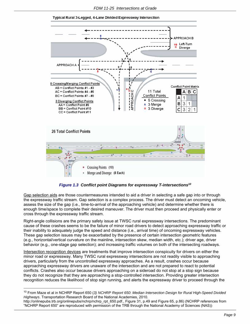
Figure 1.3 Conflict point Diagrams for expressway T-intersections10
Gap selection aids are those countermeasures intended to aid a driver in selecting a safe gap into or through the expressway traffic stream. Gap selection is a complex process. The driver must detect an oncoming vehicle, assess the size of the gap (i.e., time-to-arrival of the approaching vehicle) and determine whether there is enough time/space to complete their desired maneuver. The driver must then proceed and physically enter or cross through the expressway traffic stream.
Right-angle collisions are the primary safety issue at TWSC rural expressway intersections. The predominant cause of these crashes seems to be the failure of minor road drivers to detect approaching expressway traffic or their inability to adequately judge the speed and distance (i.e., arrival time) of oncoming expressway vehicles. These gap selection issues may be exacerbated by the presence of certain intersection geometric features (e.g., horizontal/vertical curvature on the mainline, intersection skew, median width, etc.); driver age, driver behavior (e.g., one-stage gap selection); and increasing traffic volumes on both of the intersecting roadways.
Intersection recognition devices are treatments that improve intersection conspicuity for drivers on either the minor road or expressway. Many TWSC rural expressway intersections are not readily visible to approaching drivers, particularly from the uncontrolled expressway approaches. As a result, crashes occur because approaching expressway drivers are unaware of the intersection and are not prepared to react to potential conflicts. Crashes also occur because drivers approaching on a sideroad do not stop at a stop sign because they do not recognize that they are approaching a stop-controlled intersection. Providing greater intersection recognition reduces the likelihood of stop sign running, and alerts the expressway driver to proceed through the
10 From Maze et al in NCHRP Report 650 (3) NCHRP Report 650: Median Intersection Design for Rural High-Speed Divided Highways. Transportation Research Board of the National Academies, 2010. http://onlinepubs.trb.org/onlinepubs/nchrp/nchrp_rpt_650.pdf., Figure 31, p.49 and Figure 65, p.86) (NCHRP references from “NCHRP Report 650” are reproduced with permission of the TRB through the National Academy of Sciences (NAS))

FDM 11-25 Intersections at Grade
Page 10
intersection with caution.
Traditionally, these treatments are the first countermeasures used when right-angle crashes begin to occur at TWSC rural expressway intersections because they are relatively low-cost and easy to deploy. However, lack of intersection recognition (i.e., STOP sign violation) is not the major contributing factor in the majority of right-angle crashes occurring at TWSC rural intersections. Therefore, these treatments do not address the predominant cause of right-angle crashes, which seems to be gap selection.
1.3.1.2 Median Width at Unsignalized Median Openings on Rural Expressways
The median width at a rural expressway intersection is usually the median width for the entire expressway corridor. However, the major function of a median differs between intersections versus at intersections. The major function of the median between intersections is to separate opposing expressway traffic; the major function of the median at intersections is to provide a refuge area for left-turning and U-turning expressway traffic as well as for left-turning and crossing traffic from the minor road. A median width of 40-feet or wider is adequate for expressway drivers to experience a sense of separation from opposing traffic. However, research has shown that wider medians are safer at unsignalized TWSC rural expressway intersections, most likely because wider medians allow for two-stage gap selection (i.e., a minor road driver can safely stop in the median area to evaluate the adequacy of the gap in expressway traffic coming from the right before completing a crossing or left-turn maneuver).11 A wider median at an intersection also serves as an intersection recognition device for expressway traffic by emphasizing the presence of the upcoming intersection.
The minimum median width at an intersection for two-stage gap selection is the length of the design vehicle plus 3-feet of clearance to the expressway thru-lanes from both the front and the rear of the vehicle. However, some drivers may perceive this as being too narrow because it places them across the expressway left-turn lane(s). These drivers may feel that they have no option but to complete the crossing or left-turning maneuver in one stage. Therefore, it is desirable to provide additional median width so that vehicles stored in the median do not block the expressway left-turn lane approaching from their right but still have a minimum 3-foot clearance from the expressway thru-lanes. Additional median width may also be desirable to allow more of the deceleration to take place within the median.
The standard median width of 50 or 60-feet will provide storage for cars or small trucks, but is not adequate for storing long trucks or combinations of connected farm equipment. Provide a wide median where possible if the divided highway intersects a side road on a curve or at any location to accommodate long trucks or combinations of farm machinery. The median should be at least 100 feet wide, up to approximately 150 feet wide to accommodate long trucks like the WB-65 or combinations of farm machinery that produce a long train of connected equipment.
Median roadways wider/longer than 150 feet can cause problems as well. Consider appropriate signing to prevent Wrong Way entry onto the expressway facility.
There are fewer operational problems at rural unsignalized intersections as the median width increases, but the rate of undesirable maneuvers increases as the median opening length increases.12 In other words, the geometrics of a wide median in combination with a smaller median opening help create the impression that there is not much choice in traversing the median except to follow the path the designer intended. Median delineation is another way to emphasize this desired path.
1.3.1.3 Median Signage and Delineation13
Median signage and delineation have four major objectives:
1. Inform minor road drivers that they have reached a divided highway intersection;
2. Establish the right-of-way between median and far-side expressway traffic;
3. Communicate the appropriate gap selection process (i.e., one or two-stage); and
4. Define the proper travel paths through the median roadway.
If a median is wide enough to store a passenger car, then stop or yield bars in conjunction with STOP or YIELD signs may be used to establish right-of-way and to communicate the appropriate two-stage gap selection
11 See Harwood et al in NCHRP Report 375 (4) NCHRP 375: Median Intersection Design. TRB, National Research Council, 1995. 12 See Harwood et al in NCHRP Report 375 (4) NCHRP Report 375: Median Intersection Design. TRB, National Research Council, 1995. 13 From Maze et al in NCHRP Report 650 (3) NCHRP Report 650: Median Intersection Design for Rural High-Speed Divided Highways. Transportation Research Board of the National Academies, 2010. http://onlinepubs.trb.org/onlinepubs/nchrp/nchrp_rpt_650.pdf., pp. 58-59)
FDM 11-25 Intersections at Grade
Page 11
behavior to the minor road driver. Generally, median yield control is encouraged unless the selected design vehicle can be completely stored within the median area. Do not use this marking and signing if the median is not wide enough to store a passenger car, i.e., if all vehicles require one-stage gap selection.
On median roadways wider than 120 feet, provide double yellow pavement marking to separate the opposing traffic and provide stop bars and STOP signs at each end of the median roadway. This signing and pavement marking combination effectively provides a measure of depth perception to communicate to the minor road driver that the median is wide enough for vehicle storage, thereby promoting two-stage gap selection behavior. Often, rural expressway intersections with wide medians have large expanses of pavement that can make it difficult for drivers to decide what path to follow and to anticipate the paths other drivers will take. The double yellow median centerline should help to provide visual continuity with the centerline of the minor road approaches and to define the desired vehicle paths through the median roadway. Slotted left turn lanes are generally not desirable for this configuration.
1.3.2 J-Turn Intersection
The J-turn is an example of a reduced-conflict intersection that WisDOT has used on expressways. Justify selection of a J-turn or other reduced-conflict intersections (or interchanges) using the Intersection Control Evaluation (ICE) process described in FDM 11-25-3. J-turn implementation on WisDOT projects will be on a pilot basis for the time being. Regions must coordinate with BPD and BTO in the evaluation and design. However, all expressway intersections considered for new or a change in traffic control where a J-Turn is identified as a feasible alternative, the J-Turn shall be considered as a traffic control alternative in the Intersection Control Evaluation (ICE).
The J-turn intersection combines a directional median (which allows direct left-turn exits from the expressway, but prohibits sideroad traffic from entering the median) with downstream median U-turns. Left turning and crossing traffic from the sideroad makes these maneuvers indirectly by turning right, weaving to the left, making a downstream U-turn, and then returning to the intersection to complete their desired maneuver.
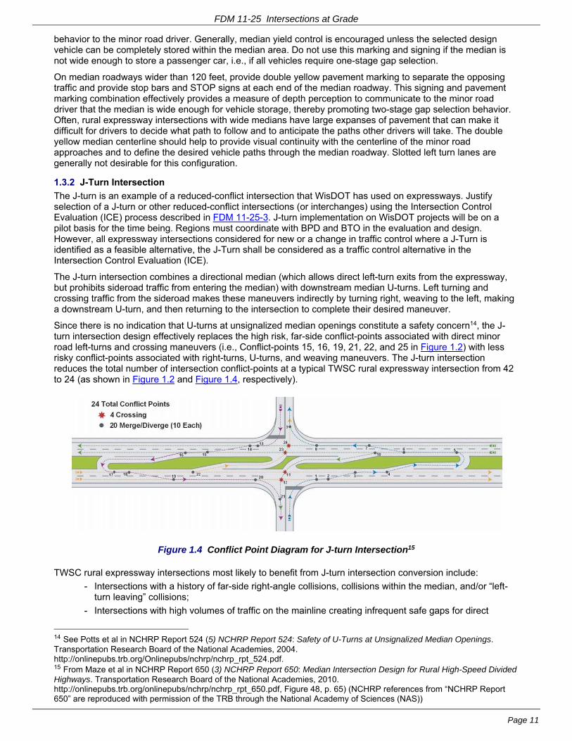
Since there is no indication that U-turns at unsignalized median openings constitute a safety concern14, the J-turn intersection design effectively replaces the high risk, far-side conflict-points associated with direct minor road left-turns and crossing maneuvers (i.e., Conflict-points 15, 16, 19, 21, 22, and 25 in Figure 1.2) with less risky conflict-points associated with right-turns, U-turns, and weaving maneuvers. The J-turn intersection reduces the total number of intersection conflict-points at a typical TWSC rural expressway intersection from 42 to 24 (as shown in Figure 1.2 and Figure 1.4, respectively).
Figure 1.4 Conflict Point Diagram for J-turn Intersection15
TWSC rural expressway intersections most likely to benefit from J-turn intersection conversion include:
- Intersections with a history of far-side right-angle collisions, collisions within the median, and/or “left-turn leaving” collisions;
- Intersections with high volumes of traffic on the mainline creating infrequent safe gaps for direct
14 See Potts et al in NCHRP Report 524 (5) NCHRP Report 524: Safety of U-Turns at Unsignalized Median Openings. Transportation Research Board of the National Academies, 2004. http://onlinepubs.trb.org/Onlinepubs/nchrp/nchrp_rpt_524.pdf. 15 From Maze et al in NCHRP Report 650 (3) NCHRP Report 650: Median Intersection Design for Rural High-Speed Divided Highways. Transportation Research Board of the National Academies, 2010. http://onlinepubs.trb.org/onlinepubs/nchrp/nchrp_rpt_650.pdf, Figure 48, p. 65) (NCHRP references from “NCHRP Report 650” are reproduced with permission of the TRB through the National Academy of Sciences (NAS))

FDM 11-25 Intersections at Grade
Page 12
crossing or left-turn maneuvers, while still having frequent enough gaps for safe right-turn entry
- Intersections with relatively low volumes of traffic crossing or turning left from the minor roads; and
- Intersections with poor horizontal and/or vertical alignment
Limited experience with the J-turn intersection design on rural expressways in Maryland and North Carolina have shown that the design can offer superior safety performance as compared with a typical TWSC rural expressway intersection. The implementation at the four sites examined completely eliminated far-side right-angle collisions and improved overall safety.
There are some potential issues in using J-turns at high-speed rural expressway intersections because J-turns are a relatively recent application:
- Design guidance and standards are still evolving.
- There are no traffic volume or level-of-service warrants.
- Signing and marking - a J-turn essentially creates three (3) separate intersections and drivers need clear and timely direction in order to make the correct decision.
- Public acceptance
J-turn design considerations include:
- Operational and safety comparison with other intersection alternatives using the ICE process described in FDM 11-25-3 A J-turn is essentially three separate intersections. Each of these intersections are evaluated separately but compared collectively to other intersection alternatives
- Intersection Sight Distance (ISD) The ISD for the mainline left turn into the side road is based on Case F; the ISD for the u-turn locations is based on Case B1; the ISD for the sideroad right turns is based on Case B2 (see FDM 11-10-5.1.4)
- Separation between the sideroad intersection and the u-turn locations - this distance represents a trade-off between providing sufficient space for safe/functional weaving, U-turn storage, and approach signing, while minimizing the travel distance/time of the indirect left-turn and crossing maneuvers. Use the following guidelines:
- As a rule of thumb, provide 7-10 seconds per lane16 to the begin taper for the U-turn lane - and check the adequacy during design (e.g., a vehicle crossing 2-lanes at 70 mph requires 1450-feet using 7-sec per lane; and 2060-feet using 10-sec per lane);
- Do not place median openings within the functional length of intersection of any of the three intersections comprising the j-turn;
- Provide adequate distance for advance signing
- Do not locate u-turns opposite driveways or streets
- Check weaving
- Geometry
- Provide positive offsets for opposing left turn lanes
- Accommodate u-turning vehicles. Possible treatments include increased median width, loons, and jughandles;
- Consider positive offsets for right turn lanes
- Side road islands and directional median islands need to reinforce left-out and thru movement restrictions
- Checking and accommodating OSOW vehicles if required (see Table 2.2 and Figure 2.5; coordinate with the region freight operations unit)
- Accommodate bicyclists and pedestrians if appropriate
1.4 Truck Routes and Routes for Oversized-Overweight (OSOW) Vehicles
There are three (3) categories of truck routes on the STH:
1. “Designated Long Truck Routes” (no overall length limitation; MAX 53' trailer w/ 43' king pin to rear axle; MAX 28’-6” trailers on double bottoms).
2. “75' Restricted Truck Routes” (75-ft overall length limitation; MAX 53' trailer, 43' king pin to rear axle;
16 (6) Innovative Intersection Designs. (DRAFT PowerPoint presentation for 2009 ACEC/WisDOT Transportation Improvement Conference). SRF Consulting Group, Inc., 2009.
FDM 11-25 Intersections at Grade
Page 13
no double bottoms).
3. “65' Restricted Truck Routes” (65-ft overall length limitation; MAX 48' trailer, no double bottoms).
See SS 348 and Administrative Code Trans 276 for requirements and definitions for these routes. Trans 276 has a listing of “Designated Long Truck Routes” and 65’ Restricted Truck Routes (Note: there are non-STH routes on this list as well). If a STH is not listed as either a “Designated Long Truck Route” or a “65' Restricted Truck Route” then it is a “75' Restricted Truck Route”. The “Wisconsin long truck operator map” includes these identified routes and is available at:
http://dot.wi.gov/osowmaps
All Federally Designated Long Truck Routes in Wisconsin (i.e. the National Network as defined in 23 CFR Part 658) are Wisconsin “Designated Long Truck Routes”. Wisconsin has also identified additional "Designated Long Truck Routes” which are not all Federally Designated Truck Routes. The design requirements for Federally Designated Truck Routes differ somewhat from other Wisconsin “Designated Long Truck Routes” (See FDM 11-15-1, FDM 11-20-1).
In addition to the Long Truck Route Maps, WisDOT has established a statewide OSOW Truck Route (OSOW-TR).
Vehicles that exceed the maximum legal dimensions and weights are OSOW. These vehicles require a permit. 17 The required permits fall into two general categories:
1. single-trip (OSOW ST); and
2. multiple-trip (OSOW-MT)
See FDM 11-25-2.1.1 for more information on OSOW vehicles.
See the OSOW maps for routes designated as OSOW-TR located at:
http://dot.wi.gov/osowmaps
Refer to FDM 11-25-2.11 for a discussion and description of OSOW vehicles.
See the following sections of FDM 11-25 for additional design guidance for intersections on the OSOW-TR:
FDM 11-25-1 General 1.1 Design Considerations
1.2 Urban Intersections
1.3 Rural Intersections
1.3.2 J-Turn intersection
1.4 Truck Routes and Routes for Oversized-Overweight (OSOW) Vehicles
FDM 11-25-2 Design Criteria and Guidelines
2.1 Design Vehicles
2.1.1 OSOW vehicles
2.1.1.1 SingleTrip Permit OSOW vehicles (OSOW-ST)
2.1.1.2 MultipleTrip Permit OSOW vehicles (OSOW-MT)
2.1.1.3 OSOW Vehicle Inventory Evaluation Overview
2.1.2 Selecting Vehicles for Intersection Design and OSOW Vehicle Checks
Table 2.2 Intersections where Checking OSOW-ST or OSOW-MT Vehicles is Required
Figure 2.5 WisDOT’s Interim Policy on Checking Criteria for OSOW-ST and OSOW-MT Vehicles at intersections
2.2 Physical and Functional Areas of an Intersection
2.2.2 Upstream Functional Length of Intersection
Table 2.5 Queue Storage (d4) for STH Intersections
2.3 Turn Bays
Table 2.6 Full-Width Turn-Lane Length for Urban Streets and Low Speed Rural
17 SS 348.25(1) states “No person shall operate a vehicle on or transport an article over a highway without first obtaining a permit therefore as provided in s. 348.26 or 348.27 if such vehicle or article exceeds the maximum limitations on size, weight or projection of load imposed by this chapter.”
FDM 11-25 Intersections at Grade
Page 14
2.6 Intersection Vertical Alignment
2.8 Angle of Intersection
FDM 11-25 Attachment 2.1 WisDOT Vehicle Inventory of OSOW Vehicles
FDM 11-25-3 Intersection Control Evaluation
3.2.2 Alternative Selection
Table 3.1 Intersection Control Evaluation - Alternative Selection
3.2.3 Appendices
FDM 11-25-5 LeftTurn Lanes
5.2 Warranting Criteria
5.3 Design Criteria
5.3.2 Median End Treatment
5.4 Special Designs
5.4.1 Slotted Left-Turn Lanes
FDM 11-25-10 Right-Turn Lanes
10.2 Intersections in Rural and Developing Areas
10.2.1 Storage Length
FDM 11-25-15 Turning Roadways (Channelized Right)
15.1 Criteria
FDM 11-25-25 Channelization
25.2 Islands
FDM 11-25-40 Railroad Crossings
40.1 General
1.4.1 OSOW High Clearance Routes
The Department has adopted OSOW High Clearance Routes with the objective of minimizing overhead constraints for OSOW vehicles along these routes. Refer to FDM 11-10-5.4.3 for further vertical clearance guidance along the high clearance routes. If an OSOW High Clearance Route has railroad crossing(s) requiring overhead railroad signals, conduct railroad signal coordination as described in FDM 11-25-40.1.
1.5 References
1. A Policy on Geometric Design of Highways and Streets 2004, 5th edition. AASHTO, Washington, DC, 2004.
2. ORDOT Highway Design Manual ch. 9.0: Intersection and Interchange Design. Oregon Department of Transportation, 2008. ftp://ftp.odot.state.or.us/techserv/roadway/web_drawings/HDM/Rev_E_2003Chp09.pdf. Accessed 8-6-2010.
3. Maze, T. H., J. L. Hochstein, R. R. Souleyrette, CTRE - Iowa State University, H. Preston, and R. Storm. NCHRP Report 650: Median Intersection Design for Rural High-Speed Divided Highways. Transportation Research Board of the National Academies, Washington, DC, 2010. http://onlinepubs.trb.org/onlinepubs/nchrp/nchrp_rpt_650.pdf. Accessed 5-18-2010. 18
18 [Dec 3, 2012 email from Ellen Chafee, Editor, CRP-TRB] The TRB through the National Academy of Sciences (NAS) grants permission to use the material listed below from Maze et al. (2010) NCHRP Report 650: Median Intersection Design for Rural High-Speed Divided Highways and J. A. Bonneson and M. D. Fontaine (2001) NCHRP Report 457: Engineering Study Guide for Evaluating Intersection Improvements in a proposed revision to Chapter 11, Section 25 of Wisconsin DOT’s Facilities Development Manual (FDM 11-25). NCHRP Report 650 Table 19 p. 47 NCHRP Report 650 Figure 117 p. 148 NCHRP Report 650 Figure 31 p. 49 NCHRP Report 650 Figure 65 p. 86 NCHRP Report 650 Figure 48 p. 65 NCHRP Report 457 Figure 2.6 p. 23 NCHRP Report 457 Figure 2-6.xls Interactive spreadsheet in online version Permission is also granted for any subsequent versions of the Work, including versions made for use with blind or physically handicapped persons, and all foreign-language translations of the Work prepared for distribution throughout the world. Permission is given with the understanding that inclusion of the material will not be used to imply Transportation Research Board, AASHTO, Federal Highway Administration, Transit Development Corporation, Federal Transit Administration, Federal
FDM 11-25 Intersections at Grade
Page 15
4. Harwood, D. W., M. T. Pietrucha, M. D. Wooldridge, R. E. Brydia, and K. Fitzpatrick. NCHRP Report 375: Median Intersection Design. TRB, National Research Council, Washington, DC, 1995.
5. Potts, I. B., D. W. Harwood, D. J. Torbic, K. R. Richard, J. S. Gluck, H. S. Levinson, P. M. Garvey, and R. S. Ghebrial. NCHRP Report 524: Safety of U-Turns at Unsignalized Median Openings. Transportation Research Board of the National Academies, Washington, DC, 2004. http://onlinepubs.trb.org/Onlinepubs/nchrp/nchrp_rpt_524.pdf.
6. Eyler, D. Innovative Intersection Designs. (DRAFT PowerPoint presentation for 2009 ACEC/WisDOT Transportation Improvement Conference). SRF Consulting Group, Inc., Plymouth, MN, Feb. 25, 2009.
LIST OF ATTACHMENTS
Attachment 1.1 Selection Criteria for Rural High Speed Intersections
FDM 11-25-2 Design Criteria and Guidelines June 24, 2016
2.1 Design Vehicles
AASHTO19 has established four (4) general classes of standard vehicles:
1. Passenger cars - includes passenger cars of all sizes, sport/utility vehicles, minivans, vans, and pick-up trucks.
2. Buses - include inter-city (motor coaches), city transit, school, and articulated buses
3. Trucks - includes single-unit trucks, truck tractor-semitrailer combinations, and truck tractors with semitrailers in combination with full trailers
4. Recreational vehicles - includes motor homes, cars with camper trailers, cars with boat trailers, motor homes with boat trailers, and motor homes pulling cars.
For purposes of geometric design, each standard vehicle has larger physical dimensions and a larger minimum turning radius than those of almost all vehicles in its class. 20
For intersection geometric design, the most important attribute of a design vehicle is its turning radius, which affects the pavement corner radius, left-turn radii, lane widths, median openings, turning roadways, and ultimately, the size of the intersection. The design vehicle may also affect the choice of intersection traffic control or intersection type and the need for auxiliary lanes.21
The turning radius of a vehicle determines the ease and comfort of making the turning maneuver. The smaller the turning radius, the larger the off-tracking of the vehicle and the slower the speed. Forcing large vehicles to use very small turning radii forces the driver to perform a very slow maneuver. Tighter radii are typically chosen for low speed and/or urban intersections, while larger radii are selected for higher speeds and rural intersections. 22,23
See the following sections in chapter 9 of the 2004 AASHTO GDHS24 for guidance on turning paths, clearances, encroachments and assumed speed of turning vehicles at intersections:
Aviation Administration, or Federal Motor Carriers Safety Administration endorsement of a particular product, method, or practice. Permission is also provided on condition that appropriate acknowledgment will be given as to the source material. 19 AASHTO GDHS 2004 (1) A Policy on Geometric Design of Highways and Streets 2004, 5th edition. AASHTO, 2004., Ch. 2, p.15, “Design Vehicles / General Characteristics” 20 Florida Intersection Design Guide 2007 (7) Florida Intersection Design Guide, Florida DOT, 2007. http://www.dot.state.fl.us/rddesign/FIDG-Manual/FIDG2007.pdf ,sect. 3.4, “Design Vehicles” 21 MADOT Highway Department Project Development & Design Guide (8 MADOT Highway Department Project Development & Design Guide ch. 6: Intersection Design. Massachusetts Department of Transportation - Highway Division, 2006. http://www.mhd.state.ma.us/downloads/designGuide/CH_6_a.pdf, Sect. 6.3.3, “Motor Vehicles 22 ORDOT Highway Design Manual (2) Highway Design Manual ch. 9.0: Intersection and Interchange Design. Oregon Department of Transportation, 2008. ftp://ftp.odot.state.or.us/techserv/roadway/web_drawings/HDM/Rev_E_2003Chp09.pdf, Ch. 9, pp.14-15, “Intersection and Interchange Design” 23 ILDOT Bureau of Design and Environment Manual 2002 (9) ILDOT Bureau of Design and Environment Manual ch. 36: Intersections. Illinois DOT, 2002. http://www.dot.state.il.us/desenv/BDE%20Manual/BDE/pdf/chap36.pdf sect. 36-1.08(a), “Design Vehicles Types” 24 (1) A Policy on Geometric Design of Highways and Streets 2004, 5th edition. AASHTO, 2004.
FDM 11-25 Intersections at Grade
Page 16
Right-turning vehicles:
- Types of Turning Roadways; pp.583-621
- Turning Roadways with Corner Islands; pp.634-639
- Free-Flow Turning Roadways at Intersections; pp.639-639
Left-turning vehicles:
- Median Openings; pp.689-704
- Auxiliary Lanes; pp.713-723
2.1.1 Oversized Overweight (OSOW) Vehicles
See FDM 11-25-1.4 for a discussion of the OSOW Truck Route (OSOW-TR). OSOW vehicles are non-standard vehicles that exceed the legal vehicle dimensions and require a permit25. OSOW vehicles fall into two general categories:
1 Single-trip permit OSOW vehicle (OSOW-ST) (see FDM 11-25-2.1.1.1)
2 Multiple-trip permit OSOW vehicle (OSOW-MT) (see FDM 11-25-2.1.1.2) (Note: Although a combine is listed as an OSOW-MT, it is an implement of husbandry and does not require a permit.)
The OSOW vehicle inventory on Attachment 2.1 shows vehicles of various configurations for which templates are available for use with truck turning software to check if the OSOW vehicles will be able to negotiate an intersection.
Figure 2.5 shows WisDOT’s interim policy for checking OSOW-ST and OSOW-MT vehicles at intersections. Table 2.2 shows intersections where checking OSOW-ST and OSOW-MT vehicles is required. See FDM 11-25-2.1.1.1 and FDM 11-25-2.1.1.2 for guidance on accommodating OSOW vehicles.
2.1.1.1 Single-Trip Permit OSOW Vehicles (OSOW-ST)
Single-trip permit OSOW vehicles (OSOW-ST) are very large loads that exceed legal length, height, weight and/or width. The permits are on a load specific and route-specific basis. These vehicles generally have an overall length greater than 150 feet, and typically are required to incorporate rear steering maneuverability. Escorts are typically required.
There are five (5) representative Single-trip permit OSOW vehicles (OSOW-ST) shown on the WisDOT vehicle inventory (see Attachment 2.1, pages 1-2):
1. 5-axle expandable-deck lowboy (DST Lowboy)
2. Wind Tower 80 M MID
3. Wind Tower 205'
4. 55 Meter Wind Blade
5. 165’ Beam
WisDOT evaluated the swept path of numerous vehicles to create the OSOW-ST vehicle library. The library should be evaluated as a set, and not as an individual vehicle, which may be known to traverse the intersection. It is estimated that if these five (5) vehicles are accommodated by the intersection then additional OSOW-ST vehicles will be accommodated as well within the proposed traffic control and intersection design.
On new construction, reconstruction and pavement replacement projects, identify and check the specific through and turning movements of OSOW-ST vehicles at each intersection on the OSOW-TR (or on non-OSOW-TR where OSOW-ST vehicles are known to travel), including intersections with other OSOW-TR locations (see Table 2.2). Examples include:
- Turning movements onto county or local roads to the OSOW-ST origin such as a manufacturing plant or gravel pit
- Freeway interchange off-on ramp terminals at the crossroad for a through movement,
- A turning movement where it is known that the OSOW-ST loads will turn.
- Through or turning movements at a roundabout (see FDM 11-26)
- Through movement from a stop-controlled side road across a non-stop controlled mainline
25 SS 348.25(1) states “No person shall operate a vehicle on or transport an article over a highway without first obtaining a permit therefore as provided in s. 348.26 or 348.27 if such vehicle or article exceeds the maximum limitations on size, weight or projection of load imposed by this chapter.”
FDM 11-25 Intersections at Grade
Page 17
On other 3R Projects (i.e., non pavement replacement) it is often possible to correct impediments to freight with minor intersection improvements (e.g., paved islands, mountable noses, etc). Identify and check the specific through and turning movements of OSOW-ST vehicles at each intersection on the OSOW-TR (or on non-OSOW-TRs where OSOW-ST vehicles are known to travel), including intersections with other truck route locations (see Table 2.2). Evaluation can be completed using aerial photographs and OSOW-ST vehicle inventory. Discuss identified Impediments with the regional freight coordinator and planning unit to review scope and funding options.
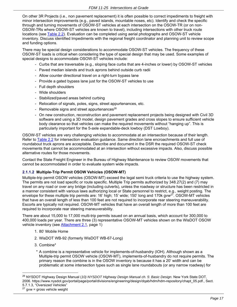
There may be special design considerations to accommodate OSOW-ST vehicles. The frequency of these OSOW-ST loads is critical when considering the type of special design that may be used. Some examples of special designs to accommodate OSOW-ST vehicles include:
- Curbs that are traversable (e.g., sloping face curbs that are 4-inches or lower) by OSOW-ST vehicles
- Paved median islands and truck aprons behind outside curb radii
- Allow counter directional travel on a right-turn bypass lane
- Provide a gated bypass lane just for the OSOW-ST vehicles to use
- Full depth shoulders
- Wide shoulders
- Stabilized/paved areas behind curbing
- Relocation of signals, poles, signs, street appurtenances, etc.
- Removable signs and street appurtenances26
- On new construction, reconstruction and pavement replacement projects being designed with Civil 3D software and using a 3D model, design pavement grades and cross slopes to ensure sufficient vehicle body clearance so that vehicles can make the required movements without “hanging up”. This is particularly important for the 5-axle expandable-deck lowboy (DST Lowboy).
OSOW-ST vehicles are very challenging vehicles to accommodate at an intersection because of their length. Refer to Table 2.2 for intersection evaluation guidance. Same direction lane encroachments and full use of roundabout truck aprons are acceptable. Describe and document in the DSR the required OSOW-ST check movements that cannot be accommodated at an intersection without excessive impacts. Also, discuss possible alternative routes for those movements.
Contact the State Freight Engineer in the Bureau of Highway Maintenance to review OSOW movements that cannot be accommodated in order to evaluate system wide impacts.
2.1.1.2 Multiple-Trip Permit OSOW Vehicles (OSOW-MT)
Multiple-trip permit OSOW vehicles (OSOW-MT) exceed the legal semi truck criteria to use the highway system. The permits are not load specific or route specific. Multiple Trip permits authorized by 348.27(2) and (7) may travel on any road or over any bridge (including culverts), unless the roadway or structure has been restricted in a manner consistent with various laws authorizing local or State personnel to restrict, e.g., weight posting. The envelope for these multiple trip permits are: 16’ high; 15’ wide; 150’ long and 170k gvw27. OSOW-MT vehicles that have an overall length of less than 100 feet are not required to incorporate rear steering maneuverability. Escorts are typically not required. OSOW-MT vehicles that have an overall length of more than 100 feet are required to incorporate rear steering maneuverability.
There are about 15,000 to 17,000 multi-trip permits issued on an annual basis, which account for 300,000 to 400,000 loads per year. There are three (3) representative OSOW-MT vehicles shown on the WisDOT OSOW vehicle inventory (see Attachment 2.1, page 1)
1. 80’ Mobile Home
2. WisDOT WB-92 (formerly WisDOT WB-67-Long)
3. Combine*
* A combine is a representative vehicle for implements-of-husbandry (IOH). Although shown as a Multiple-trip permit OSOW vehicle (OSOW-MT), implements-of-husbandry do not require permits. The primary reason the combine is in the OSOW inventory is because it has a 20’ width and can be problematic at some intersection types such as single lane roundabouts (or any narrow roadway) for
26 NYSDOT Highway Design Manual (10) NYSDOT Highway Design Manual ch. 5: Basic Design. New York State DOT, 2006. https://www.nysdot.gov/portal/page/portal/divisions/engineering/design/dqab/hdm/hdm-repository/chapt_05.pdf., Sect. 5.7.1.3, “Oversized Vehicles” 27 gvw = gross vehicle weight

FDM 11-25 Intersections at Grade
Page 18
signs, power poles, light poles to make sure they are far enough from the roadway.
On new construction, reconstruction and pavement replacement projects identify and check the specific through and turning movements of OSOW-MT vehicles at STH intersections with an STH or a truck route or at truck route intersections with an STH or a truck route (unless restricted as noted above). Also, check OSOW-MT movements at the same intersections as OSOW-ST movements (see FDM 11-25-2.1.1.1 and Table 2.2).
On other 3R Projects (i.e., non pavement replacement) it is often possible to correct impediments to freight with minor intersection improvements (i.e. paved islands, mountable noses, etc). Identify and check the specific through and turning movements of OSOW-MT vehicles at each intersection on the OSOW Truck Route (OSOW-TR) (or on non-OSOW Truck Routes where OSOW-MT vehicles are known to travel), including intersections with other OSOW-TR locations (see Table 2.2). Evaluation can be completed using aerial photographs and OSOW-ST vehicle inventory. Discuss identified impediments with the regional freight coordinator and planning unit to review scope and funding options.
The WB-92 (formerly WB-67-Long) is a very challenging vehicle to accommodate at an intersection because of its length and its lack of rear steering. Refer to Attachment 2.2 for intersection evaluation guidance. Lane encroachments and full use of roundabout truck aprons are acceptable. Describe and document in the DSR the required OSOW-MT check movements that cannot be accommodated at an intersection without excessive impacts. Also, discuss possible alternative routes for those movements.
Coordinate the intersection maneuverability check with the Regional freight operations unit.
2.1.1.3 OSOW Vehicle Inventory Evaluation Overview
Use AutoTurn, AutoTurn Pro 3D or Autodesk Vehicle Tracking (AVT) software for OSOW horizontal evaluation (see FDM 11-26 Attachment 50.3) with the exception of the Wind Tower 80 M MID and Wind Tower 205’. For these vehicles, only use AutoTurn or AutoTurn Pro 3D. Use AutoTurn Pro 3D or Autodesk Vehicle Tracking for low clearance evaluation (DST lowboy). Refer to these links for videos and assistance in using these tools.
This is the link to the AutoTURN Pro tutorial videos:
ftp://ftp.dot.wi.gov/dtsd/bpd/methods/ground-clearance-training
The following OSOW-ST vehicles in the OSOW library have rear steering capabilities:
- 55 Meter Wind Blade
- 165' Beam
- Wind Tower 80 M MID
- Wind Tower 205'
The Wind Tower 80 MID and Wind Tower 205’ are the easiest to drive because the rear steering is linked to the front. Just drive the vehicle and the rear steers itself. Designers shall not manually steer the rear components of these vehicles when evaluating movements.
The 55 Meter Wind blade and the 165' Beam can be more complicated to accommodate because they have rear steering that is completely independent of what the front axle is doing. For those vehicles, initiating a swept path command will produce a dialog box with a check box called "Manual Steer". Place a check in that box to control the steering of the rear axles (see Figure 2.1). In AutoCAD Civil 3D, the rear steering is then controlled by holding the Ctrl key and using the mouse wheel to move through the swept path. When manually steering a vehicle, the designer shall not steer the rear wheels at a rate greater than 4 Degrees for every 17 feet of travel. See the following video for guidance.
http://www.c3dkb.dot.wi.gov/video/dsn-chk/swept-pth/swept-pth-beam-trnsprt-01.mp4

FDM 11-25 Intersections at Grade
Page 19
Figure 2.1 Checkbox to Control Rear Steering
2.1.2 Selecting Vehicles for Intersection Design28 and OSOW Vehicle Checks
Turning movements control the operations, safety, and efficiency of an intersection. If intersection geometry restricts vehicles from properly completing turning maneuvers then capacity is reduced, crash potential increases and the break down potential of the intersection increases. Each leg of an intersection handles the turning movements of various vehicle types with varying degrees of encroachment.
Intersection Design Vehicle (IDV). An Intersection Design Vehicle for an intersection turning movement is the largest standard vehicle that frequently makes that turning movement. An Intersection Design Vehicle makes the turning movement without encroaching onto other lanes (including a contiguous bike lane between a right turn lane and a travel lane - as illustrated in Figure 2.2 on the EB approach leg) and without encroaching onto the shoulder or gutter. Such designs help reduce collisions and operational delays from lane encroachments. (Note: A right-turning Intersection Design Vehicle may encroach onto a bike lane that is contiguous to the gutter, i.e., to the right of a right-turning vehicle- as illustrated in Figure 2.2 on the EB departure leg).
Intersection Check Vehicle (ICV). An Intersection Check Vehicle for an intersection turning movement is larger than the Design Vehicle and makes the turn less frequently than the Design Vehicle. An Intersection Check Vehicle makes the turning movement by swinging wide and encroaching onto other traffic lanes (including bike lanes) without disrupting traffic significantly. Desirably an Intersection Check Vehicle will not encroach into opposing travel lanes or leave the roadway (i.e., drive up on the curb or encroach beyond the shoulder), but this is not always practical or cost effective - particularly for OSOW vehicles or for turns made from/to low-speed, low-volume local streets in urban areas.
For design purposes, assume that parking stalls are occupied and therefore unavailable for the movements of Intersection Design Vehicles and Intersection Check Vehicles.
Figure 2.2 illustrates the concept of Intersection Design Vehicle vs. Intersection Check Vehicle.
28 ORDOT Highway Design Manual (2) ORDOT Highway Design Manual ch. 9.0: Intersection and Interchange Design. Oregon Department of Transportation, 2008. ftp://ftp.odot.state.or.us/techserv/roadway/web_drawings/HDM/Rev_E_2003Chp09.pdf, Ch. 9, pp.14-15, “Intersection and Interchange Design” NYSDOT Highway Design Manual (10) NYSDOT Highway Design Manual ch. 5: Basic Design. New York State DOT, 2006. https://www.nysdot.gov/portal/page/portal/divisions/engineering/design/dqab/hdm/hdm-repository/chapt_05.pdf, Sect. 5.7.1, “Design Vehicle” IILDOT Bureau of Design and Environment Manual 2002 (9 ILDOT Bureau of Design and Environment Manual ch. 36: Intersections. Illinois DOT, 2002. http://www.dot.state.il.us/desenv/BDE%20Manual/BDE/pdf/chap36.pdf sect. 36-2.01(c), “Encroachment” MADOT Highway Department Project Development & Design Guide (8) MADOT Highway Department Project Development & Design Guide ch. 6: Intersection Design. Massachusetts Department of Transportation - Highway Division, 2006. http://www.mhd.state.ma.us/downloads/designGuide/CH_6_a.pdf, Sect. 6.7.2, “Pavement Corner Radius”; Sect. 6.7.2.1, “Simple Curb Radius”

FDM 11-25 Intersections at Grade
Page 20
Figure 2.2 Illustrative Turning Movements for Intersection Design and Check Vehicles
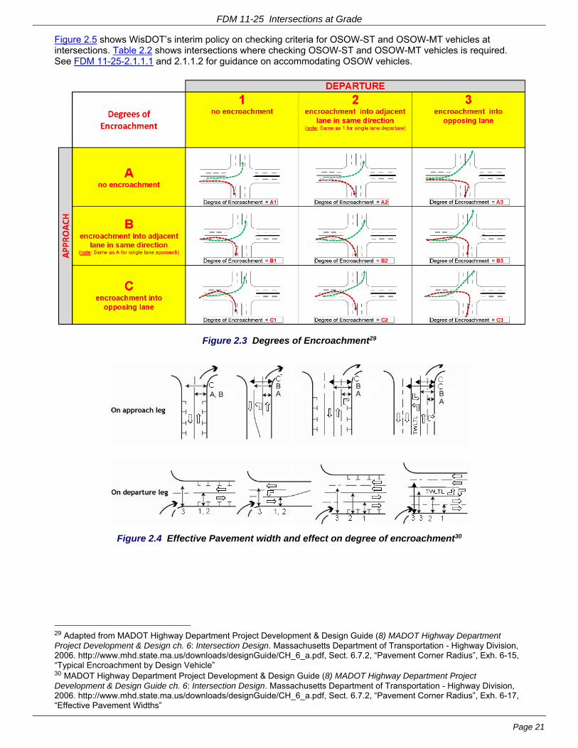
Figure 2.3 illustrates and defines the possible degrees of encroachment for intersection turning movements. The acceptable degree of encroachment for a particular vehicle type varies significantly depending on roadway type and balances the operational impacts to turning vehicles with the safety of all other users of the street.
Figure 2.4 illustrates “effective” pavement width on approach and departure legs. The “effective” pavement width is the pavement width usable under the permitted degree of encroachment. At a minimum, effective pavement width is always the right-hand lane and therefore usually at least 11-12 feet, on both the approach and departure legs. Typically, legs with on-street parking have an effective pavement width that ranges from about 20-feet, if there is no bike accommodation, to about 25-feet if there is a bike accommodation. The effective width may include encroachment into adjacent or opposite lanes of traffic, where allowed.
Table 2.1 shows the default Design Vehicle for intersection turning movements, based on the functional classifications of the intersecting highways. Potentially, each turning movement at an intersection could have a different Design Vehicle.
Table 2.1 also shows Check Vehicles and their acceptable degrees of encroachment (see Figure 2.3), based on the functional classifications of the intersecting highways.
Use Table 2.1 in conjunction with Figure 2.3 and 2.4 as a starting point for planning and design. Verify the acceptable degree of encroachment during the project development process. Considerations include traffic volumes, one-way or two-way operations, urban/rural location, construction impacts, right-of-way impacts and the type of traffic control.
FDM 11-25 Intersections at Grade
Page 21
Figure 2.5 shows WisDOT’s interim policy on checking criteria for OSOW-ST and OSOW-MT vehicles at intersections. Table 2.2 shows intersections where checking OSOW-ST and OSOW-MT vehicles is required. See FDM 11-25-2.1.1.1 and 2.1.1.2 for guidance on accommodating OSOW vehicles.
Figure 2.3 Degrees of Encroachment29
Figure 2.4 Effective Pavement width and effect on degree of encroachment30
29 Adapted from MADOT Highway Department Project Development & Design Guide (8) MADOT Highway Department Project Development & Design ch. 6: Intersection Design. Massachusetts Department of Transportation - Highway Division, 2006. http://www.mhd.state.ma.us/downloads/designGuide/CH_6_a.pdf, Sect. 6.7.2, “Pavement Corner Radius”, Exh. 6-15, “Typical Encroachment by Design Vehicle” 30 MADOT Highway Department Project Development & Design Guide (8) MADOT Highway Department Project Development & Design Guide ch. 6: Intersection Design. Massachusetts Department of Transportation - Highway Division, 2006. http://www.mhd.state.ma.us/downloads/designGuide/CH_6_a.pdf, Sect. 6.7.2, “Pavement Corner Radius”, Exh. 6-17, “Effective Pavement Widths”

FDM 11-25 Intersections at Grade
Page 22
Table 2.1 Default Intersection Design and Check Vehicles & Degree of Encroachment [DE] [A]
For Turn Made Intersection Design Vehicle [DE=A1] [C], [D],
Intersection Check Vehicle(s) [DE] ] [C] [D] From (Approach) [B] Onto (Departure) [B]
Ramp
Major Arterial or Minor Arterial or
Collector or Local
WB-65 [E] [F]
Major Arterial or Minor Arterial or
Collector or Local
Ramp WB-65 [E] [F]
Major Arterial or STH or Truck Route
Major Arterial or STH or Truck Route
WB-65 [E] [F]
Major Arterial or STH or Truck Route
Minor Arterial WB-40 SU-40 [F] WB-65 [A2] [I]
Major Arterial or STH or Truck Route
Collector WB-40 [F] WB-65 [A2] [I]
Major Arterial or STH or Truck Route
Local SU-30 [F] WB-65 [A2] [I]
Minor Arterial Major Arterial or STH or
Truck Route WB-40 SU-40 [F]
WB-65 [A2] [I]
Minor Arterial Minor Arterial WB-40 SU-40 [F] WB-65 [A2] [H]
Minor Arterial Collector WB-40 [F] WB-65 [A2] [H]
Minor Arterial Local SU-30 [F] WB-40 [A2] [H]
WB-65 [B2] [G], [I]
Collector Major Arterial or STH or
Truck Route WB-40 [F] WB-65 [B2] [G], [I]
Collector Minor Arterial WB-40 [F] WB-65 [B2] [G], [I]
Collector Collector SU-30 [F] WB-40 [A2] [H]
WB-65 [B2] [G], [I]
Collector Local SU-30 [F] WB-40 [A2] [H]
WB-65 [B3] [G]
Local Major Arterial or STH or
Truck Route SU-30 [F]
Wb-40 [B2]
WB-65 [C2] [G]
Notes for Table 2.1:
A. Intersection geometrics shall be designed using turning templates or software such as AutoTURN or Auto Track. Submit the intersection plan with turning template overlay to the Regional Traffic Unit for review.
Coordinate with the Regional freight operations unit if there will be OSOW vehicles using an intersection. See Table 2.2 for intersections where checking OSOW-ST and OSOW-MT vehicles is required. See Figure 2.5 for WisDOT’s interim policy on checking criteria for OSOW-ST and OSOW-MT vehicles at intersections. See FDM 11-25-2.1.1.1 and FDM 11-25-2.1.1.2 for guidance on accommodating OSOW vehicles. See the OSOW maps for truck routes designated as OSOW-TR located at:
http://dot.wi.gov/osowmaps
Also see FDM 11-25-1.4.
B. Functional Classification Systems Maps can be found at:
http://wisconsindot.gov/Pages/projects/data-plan/plan-res/function.aspx
FDM 11-25 Intersections at Grade
Page 23
Truck routes are shown on the Wisconsin truck operators map available at
http://wisconsindot.gov/Pages/dmv/com-drv-vehs/mtr-car-trkr/truck-routes.aspx
Also see, FDM 11-25-1.4.
C. See Figure 2.2, 2.3 and 2.4 for definitions and illustrations of Degree of Encroachment (DE)
D. A smaller Intersection Design Vehicle than shown in Table 2.1 may be appropriate at some locations but must be justified in the DSR. Conditions that might justify consideration of a smaller Intersection Design Vehicle include:
- Right-of-way is limited
- Trucks are prohibited on cross streets
- Current and projected Traffic counts show a small number of both the default Intersection Design Vehicle and vehicles that are larger than the default Intersection Design Vehicle (<1/day total) making the turn(s)
- Cross street volume is minimal (< 400 AADT) and the route is unlikely to be used as a detour route for a nearby higher volume roadway.
For 3R projects, the Intersection Design Vehicle may be site specific, if necessary, and may have a less restrictive turning radius than those for new construction and reconstruction projects. 31
A larger Intersection Design Vehicle than shown in Table 2.1 may be appropriate at some locations but must be justified in the DSR. Conditions that might justify consideration of a larger Intersection Design Vehicle include:
- Current and projected Traffic counts show a significant number of vehicles that are larger than the default Intersection Design Vehicle making the turn(s)
- The encroachment of even a few large vehicles will cause significant traffic disruption
The following conditions apply if an Intersection Design Vehicle other than shown in Table 2.1 is used:
- Use the default Intersection Design Vehicle from Table 2.1 as an Intersection Check Vehicle, and verify that it can make the turn(s) - by encroaching onto other traffic lanes if necessary - without significantly disrupting traffic. For signalized intersections, if the default Intersection Design Vehicle is a WB-65, verify that the WB-65 can make the turn(s) with a DE=A2.
- The SU or school bus design vehicles are the smallest Intersection Design Vehicles used in the design of intersections on the STH. This design reflects that, even in residential areas, garbage trucks, delivery trucks, and school buses will be negotiating turns with some frequency.
- Verify that WB-65 trucks can physically make the turns at an intersection of two truck routes without backing up and without impacting curbs, parked cars, utility poles, mailboxes, traffic control devices, or any other obstructions, regardless of the selected Intersection Design Vehicle or allowable encroachment.”
E. Check right turns with a WB-67 vehicle using DE=A1 - except encroaches onto curb flag
F. At signalized intersections, DE=A2 is acceptable for left turns from a single left turn lane if:
- Left turns are only allowed during protected phase, or
- There are no opposing vehicles (e.g., on the non-crossing leg of a T-intersection)
G. At signalized intersections, for the WB-65 Intersection Check Vehicle, use a preferred degree of encroachment (DE) = A2, with a minimum DE as shown.
H. A Degree of Encroachment (DE) = A3 may be acceptable for right turns by an Intersection Check Vehicle if there is a right-turn lane on the approach. This allows the vehicle to wait outside of the approach travel lane until traffic clears from the opposing lane on the departure leg. Use only if this is an infrequent occurrence and does not cause backups or other traffic disruptions.
I. At right-turn lanes with a contiguous bike lane between the turn lane and the travel lane, check the swept path of the WB-65 Intersection Check Vehicle to see if it is possible to avoid encroaching into the bike lane without significantly disrupting traffic or going outside of the roadway. Otherwise, consider:
- accepting infrequent bike lane encroachments but consider a warning sign that right turning
31 (9) ILDOT Bureau of Design and Environment Manual ch. 36: Intersections. Illinois DOT, 2002. http://www.dot.state.il.us/desenv/BDE%20Manual/BDE/pdf/chap36.pdf. sect. 36-1.08(b), “Selection”

FDM 11-25 Intersections at Grade
Page 24
large trucks pull left before turning.
- If bike lane encroachment is frequent enough to be potentially dangerous, consider:
- parking restrictions and/or a larger curb radius
- Mark as a shared bike/right-turn lane instead of a separate bike lane and right-turn lane
- Re-design to reduce or eliminate the conflict
Table 2.2 Intersections Where Checking OSOW-ST or OSOW-MT Vehicles is Required [A] [B] [C] [D]
Condition For Movement Made
OSOW Vehicles to Check
From (Approach Leg) To (Departure Leg)
1
OSOW-TR OSOW-TR
OR
non-OSOW-TR - with KNOWN USE by OSOW-ST vehicles
OR
Ramp [E]
OSOW-ST & OSOW-MT
check all applicable turning movements and thru
movements
non-OSOW-TR with KNOWN USE by OSOW-ST vehicles
Ramp [E]
2a [F]
OSOW-TR Any road
not included in Condition 1
OSOW-MT
check all applicable turning movements and thru
movements Ramp
2b [F] Any road
not included in Condition 1
OSOW-TR
OR
Ramp
OSOW-MT
check all applicable turning movements and thru
movements
3
STH (non-OSOW-TR) STH (non-OSOW-TR)
OR
Truck Route (non-OSOW-TR)
OSOW-MT
check all applicable turning movements and thru
movements Truck Route (non-OSOW-TR)
Notes for Table 2.2:
[A] See Figure 2.5 for WisDOT’s interim policy on checking criteria for OSOW-ST and OSOW-MT vehicles at intersections to ascertain currently known OSOW usage. Designers should consult with region freight coordinator to attain list of permitted OSOW-ST trips.
[B] Coordinate with the Regional freight operations unit if there will be OSOW vehicles using an intersection. See FDM 11-25-2.1.1, 2.1.1.1 and 2.1.1.2 for additional guidance and requirements on checking OSOW-ST and OSOW-MT vehicles.
[C] See the OSOW-TR maps for routes designated as OSOW-TR located at:
http://dot.wi.gov/osowmaps
See also, FDM 11-25-1.4.
Long Truck routes are shown on the Wisconsin Long truck operators map available at:
http://dot.wi.gov/osowmaps
See also, FDM 11-25-1.4.
[D] See FDM 11-26-10.2.2 for additional guidance on accommodating legal large vehicles.
[E] Usually, the “ramp-off / ramp-on” movement (i.e., mainline to exit ramp thru crossroad to entrance ramp to mainline) only needs to be checked if the mainline cannot accommodate the movement due to substandard roadway or structure design (e.g., low vertical clearance).

FDM 11-25 Intersections at Grade
Page 25
[F] The primary objective in checking conditions 2a and 2b is to maintain existing accommodations.
Figure 2.5 WisDOT’s Interim Policy on Checking Criteria for OSOW-ST and OSOW-MT Vehicles at Intersections (included as Attachment 2.2)
2.2 Physical and Functional Areas of an Intersection
Figure 2.6 shows the Physical and Functional Areas of an intersection.
The Physical Area of an Intersection is the pavement area where the intersecting roads coincide. The points of curvature of the intersection radii define the outer boundaries of the area32.
The Functional Area of an Intersection includes the physical area, but also extends upstream and downstream from the physical area for a distance equal to the functional length of intersection, along all of the intersection roadways. It includes any auxiliary lanes and their associated channelization.
32 AASHTO GDHS 2004 (1) A Policy on Geometric Design of Highways and Streets 2004, 5th edition. AASHTO, 2004., pp. 556-557)
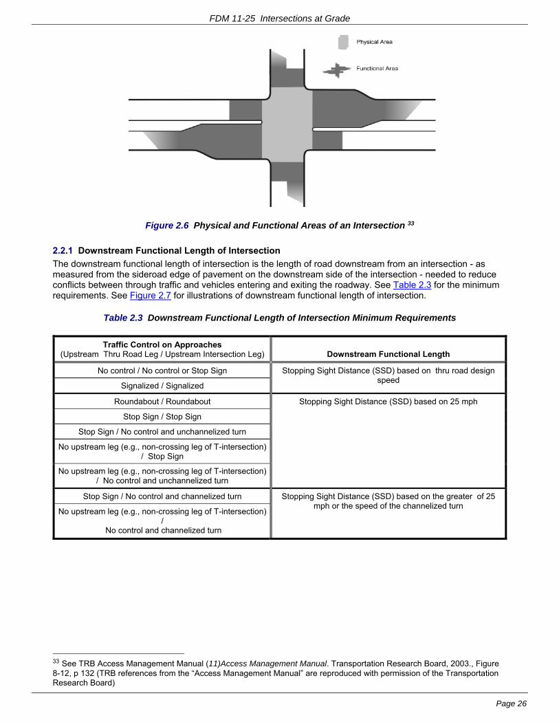
FDM 11-25 Intersections at Grade
Page 26
Figure 2.6 Physical and Functional Areas of an Intersection 33
2.2.1 Downstream Functional Length of Intersection
The downstream functional length of intersection is the length of road downstream from an intersection - as measured from the sideroad edge of pavement on the downstream side of the intersection - needed to reduce conflicts between through traffic and vehicles entering and exiting the roadway. See Table 2.3 for the minimum requirements. See Figure 2.7 for illustrations of downstream functional length of intersection.
Table 2.3 Downstream Functional Length of Intersection Minimum Requirements
Traffic Control on Approaches (Upstream Thru Road Leg / Upstream Intersection Leg) Downstream Functional Length
No control / No control or Stop Sign Stopping Sight Distance (SSD) based on thru road design speed
Signalized / Signalized
Roundabout / Roundabout Stopping Sight Distance (SSD) based on 25 mph
Stop Sign / Stop Sign
Stop Sign / No control and unchannelized turn
No upstream leg (e.g., non-crossing leg of T-intersection) / Stop Sign
No upstream leg (e.g., non-crossing leg of T-intersection) / No control and unchannelized turn
Stop Sign / No control and channelized turn Stopping Sight Distance (SSD) based on the greater of 25 mph or the speed of the channelized turn
No upstream leg (e.g., non-crossing leg of T-intersection) /
No control and channelized turn
33 See TRB Access Management Manual (11)Access Management Manual. Transportation Research Board, 2003., Figure 8-12, p 132 (TRB references from the “Access Management Manual” are reproduced with permission of the Transportation Research Board)

FDM 11-25 Intersections at Grade
Page 27
Figure 2.7 Downstream Functional Lengths of Intersection
The downstream functional length is also a parameter for access control in determining acceptable locations for median openings and minimum separation between private accesses and public road intersections (i.e., corner clearance - see FDM 11-25-2.5). Drivers making a turn at an intersection need adequate space to complete the maneuver before encountering vehicles turning into a downstream driveway. The left turn is the more complex maneuver because the driver is making it without positive guidance and must adjust speed, path, and direction.
2.2.2 Upstream Functional Length of Intersection
The upstream functional length of intersection is composed of four (4) elements as shown in Figure 2.8:
d1 = distance traveled at operating speed during the driver’s perception–reaction time (PRT). See Table 2.4.
d2 = distance traveled as a vehicle clears a thru-lane and enters a turn lane by moving laterally 9-feet while braking. This is a more complex and demanding driving task than changing lanes only or braking only. See Table 2.4. This element does not apply (i.e., d2=0-feet) to vehicles continuing in a thru-only lane or a shared turn-lane/thru-lane because there is no lateral movement).
d3 = distance traveled by vehicles in a turn lane while braking to a stop after a lateral shift from thru lane. For vehicles in a shared turn-lane/thru-lane or vehicles in a stopped/signalized thru-only lane, it is the distance traveled while braking to a stop after PRT. See Table 2.4. This element does not apply (i.e., d3=0-feet) to vehicles continuing in an unstopped/unsignalized thru-only lane because there is no deceleration).
d4 = queue storage length. Typically, use Highway Capacity Manual (HCM) or other modeling software to compute the queue storage requirement, but other methods are available. Confer with the Region traffic engineer on the appropriate software and/or method. Note that the decelerating vehicle is the last vehicle in the queue. See Table 2.5 and Table 2.6 for queue storage requirements. This element does not apply (i.e., d4=0-feet) to vehicles continuing in an unstopped/unsignalized thru-only lane because vehicles do not stop.
On the OSOW Truck Route (OSOW-TR), the storage distance (d4) may need to be adjusted to accommodate one OSOW vehicle, depending on load frequency. Increased storage distance would not be required at intersections with non-TR routes.

FDM 11-25 Intersections at Grade
Page 28
Figure 2.8 Upstream Functional Length of Intersection Elements34
34 Adapted from (12) Transportation and Land Development, 2nd edition. Institute of Transportation Engineers, 2006., p.5-43, Figure 5-20

FDM 11-25 Intersections at Grade
Page 29
Table 2.4 Upstream Functional Length of Intersection Elements d1, d2, and d3 [A]
Perception-Reaction Distance Maneuver Distance
d1
(feet)
des (min)
d2 (feet)
des (min)
d3 (feet)
des (min)
Speed mph
[B] Rural [C] [E]
Urban / Suburban
[C] [F] [C] [G] Turn lane
[D] [H] Thru lane
[C] [I]
25 90 (55) 55 (35) 75 (75) 25 (25) 100 (75)
30 110 (65) 65 (45) 95 (95) 75 (50) 145 (105)
35 130 (75) 75 (50) 110 (110) 100 (75) 195 (145)
40 145 (90) 90 (60) 130 (130) 150 (100) 255 (185)
45 165 (100) 100 (65) 150 (150) 200 (150) 325 (235)
50 185 (110) 110 (75) 165 (165) 250 (175) 400 (290)
55 200 (120) 120 (80) 185 (185) 325 (225) 485 (355)
60 220 (130) 130 (90) 205 (205) 400 (300) 580 (420)
65 240 (145) 145 (95) 225 (225) 475 (350) 680 (495)
70 255 (155) 155 (105) 240 (240) 575 (425) 785 (575)
Notes for Table 2.4
A See Table 2.5 for guidance on Upstream Functional Length of Intersection element d4 (Queue storage length)
B Use operating speed of travel lanes (except, not < 25 mph and not > design speed) - either as observed or as calculated using HCM or other appropriate method - Confer with the Region traffic engineer. Assume that free flow speed does not exceed Design Speed.
C All dimensions rounded to nearest 5-feet
D All dimensions rounded to nearest 25-feet
E Desirable distance based on a perception-reaction-time (PRT) of 2.5s. Minimum distance based on a perception-reaction-time (PRT) of 1.5s.
F Desirable distance based on a perception-reaction-time (PRT) of 1.5s. Minimum distance based on a perception-reaction-time (PRT) of 1.0s.
G Applies only to turn-lanes The d2 distance is based on an assumed deceleration rate of 5.8 fps2 based , which is based on a vehicle moving laterally 9-feet at an assumed lateral shift rate of 3 to 4 fps, while reducing its speed by 10 mph. A vehicle is assumed to have cleared the thru traffic lane when it has moved laterally 9-feet .The speed differential between the turning vehicle and following thru vehicles is 10 mph when the turning vehicle clears the thru traffic lane. .35
H Applies only to turn-lanes Distance to decelerate from [Speedminus10 mph] to [stop] Desirable d3 distance based on a deceleration rate of 6.7 fps2, which is the observed 85th-percentile rate. Minimum d3 distance based on a deceleration rate of 9.2 fps2, which is the observed 50th-percentile rate.
I Applies only to shared turn-lane/thru-lanes or stopped/signalized thru-only lanes Distance to decelerate from [Speed] to [stop] Desirable d3 distance based on a deceleration rate of 6.7 fps2, which is the observed 85th-percentile rate. Minimum d3 distance based on a deceleration rate of 9.2 fps2, which is the observed 50th-percentile rate.
35 Research shows that the crash rate is 3.3 times higher for a 20 mph speed differential than for a 10 mph speed differential; 23 times higher for a 30 mph speed differential; and 90 times higher for a 35 mph speed differential, as documented by Stover & Koepke (12) Transportation and Land Development, 2nd edition. Institute of Transportation Engineers, 2006., p.5-37). Crashes resulting from excessive speed differential can occur up to several hundred feet from the intersection as well as at the intersection itself.

FDM 11-25 Intersections at Grade
Page 30
Table 2.5 Queue Storage (d4) for STH Intersections 36 [A] [B] [C]
Thru-only Lanes
des (min) Left Turn des (min)
Right Turn des (min) Design Class
Approach Control
Rural A2, A3
No control no storage required greater of 90th pctl or 4-veh (greater of 90th pctl or 2-veh
90th pctl
Stop Sign greater of 90th pctl or 4-vehicles (greater of 90th pctl or 2-vehicles)
Signalized 50th pctl
(Check 95th pctl for backup into adjacent intersection, etc.)
greater of 95th pctl or 4-vehicles (greater of 95th pctl or 2-vehicles)
Rural other
No control no storage required greater of 90th pctl or
2-vehicles 90th pctl
Stop Sign greater of 90th pctl or 2-vehicles
Signalized 50th pctl
(Check 95th pctl for backup into adjacent intersection, etc.)
greater of 95th pctl or 2-vehicles (greater of 90th pctl or 2-vehicles)
Urban transitional/high-speed
UA2, UA3
No control no storage required greater of 90th pctl or 4- veh (greater of 90th pctl or 2- veh
90th pctl
Stop Sign greater of 90th pctl or 4-vehicles (greater of 90th pctl or 2-vehicles)
Signalized 50th pctl
(Check 95th pctl for backup into adjacent intersection, etc.)
greater of 95th pctl or 4-vehicles (greater of 95th pctl or 2-vehicles
Urban transitional/high-speed other
No control no storage required greater of 90th pctl or
2-vehicles 90th pctl
Stop Sign greater of 90th pctl or 2-vehicles
Signalized 50th pctl
(Check 95th pctl for backup into adjacent intersection, etc.)
greater of 95th pctl or 2-vehicles (greater of 90th pctl or 2-vehicles)
Urban low-speed 3, 4, 5
No control no storage required greater of 90ctl or 4- veh [D] (greater of 90th pctl or 2- veh
[D] 90th pctl
Stop Sign greater of 90ctl or 4 vehicles [D]
(greater of 90th pctl or 2-vehicles) [D]
Signalized 50th pctl
(Check 95th pctl for backup into adjacent intersection, etc.)
greater of 95ctl or *4 vehicles [D] (greater of 90th pctl or 2-vehicles) [D]
Urban low-speed other
No control no storage required greater of 90th pctl or
2 vehicles [D] 90th pctl
Stop Sign greater of 90th pctl or 2-vehicles [D] (greater of 85th pctl or 2-vehicles) [D]
Signalized 50th pctl
(Check 95th pctl for backup into adjacent intersection, etc.)
greater of 95th pctl or 2-vehicles [D] (greater of 90th pctl or 2 vehicles) [D]
all Roundabout see FDM 11-26
Notes for Table 2.5:
A pctl = percentile
B Assume vehicle length = 25-feet
C On the OSOW Truck Route (OSOW-TR), storage distance (d4) may need to be adjusted to accommodate one OSOW vehicle, depending on load frequency. Increased storage distance is not be required at intersections with non-TR routes.
D one (1) vehicle if peak turning volume < 20 vph
36 Adapted from Bonneson & Fontaine in NCHRP Report 457 (13) NCHRP Report 457: Engineering Study Guide for Evaluating Intersection Improvements. TRB, National Research Council, 2001. http://onlinepubs.trb.org/onlinepubs/nchrp/esg/esg.pdf, pp.23-25); see also Stover & Koepke (12) Transportation and Land Development, 2nd edition. Institute of Transportation Engineers, 2006., pp. 5-50 to 5-53)

FDM 11-25 Intersections at Grade
Page 31
An intersection approach may have a different upstream functional length for the thru lane(s), left-turn bay, and right-turn bay because of different queue storage requirements for those lanes. Each lane of a multi-lane approach can have a different upstream functional length. The upstream functional length for a thru lane is the longer of the functional length calculated for the thru lane and the functional length(s) calculated for the turn bay(s) adjacent to that thru lane.
The upstream functional length of intersection is not a static dimension, particularly on urban roads. It can vary because operating speeds and queue storage requirements vary during the course of a day. For example, during peak conditions, the queue storage requirement (d4) might be longer because there are more turning vehicles; but the PRT (d1) and maneuver distances (d2 & d3) might be shorter because operating speeds are lower. The opposite might be true during non-peak conditions.
Use the upstream functional length of intersection to design and evaluate turn bay lengths (see Table 2.5, “Turn Bays” for additional guidance).
In addition, upstream functional length of intersection is a parameter for access control when determining acceptable locations for median openings and minimum separation between private accesses and public road intersections (i.e., corner clearance). See the sections below on “Median Opening Locations” and “Driveways and Corner Clearance”.
2.3 Turn Bays
Turn bay length includes both the approach taper and the full width turn lane (see Figure 2.9). Providing adequate turn bay length is important because it minimizes deceleration in the thru travel lanes by turning vehicles 37, and it reduces the probability of “spillback” into the travel lane by queued turning vehicles.
Use the following guidance for determining turn bay length:
- Use the upstream functional length to design and evaluate turn bay lengths (see Figure 2.9 for the correlation of Upstream Functional Length of Intersection and Turn Bay elements).
- Calculate for both the peak and non-peak conditions and use the longer of the two to determine the length of turn bay.
- See Table 2.4 for functional length elements d1, d2, and d3 (i.e., PRT and deceleration)
- See Table 2.5 for functional length element d4 (i.e., queue storage);
- See Table 2.6 for full-width turn lane lengths
- See Attachment 2.3 for turn bay taper lengths.
- If possible, provide a turn bay length that meets desirable criteria. A design based on desirable criteria will maximize the safety, operational efficiency and capacity of an intersection approach – and provide a margin of error when conditions exceed design assumptions.
- If it is not possible to meet desirable criteria because of physical constraints or existing development then, if possible, provide a turn bay length that exceeds minimum criteria.
- If it is not possible because of physical constraints or existing development to exceed minimum criteria then provide a turn bay length that meets minimum criteria.
- If it is not possible to meet minimum criteria, look at removing or relocating the physical constraint. If that is not possible, it may be necessary to close the median opening or restrict movements if it is not possible to provide a proper left turn lane. As a last resort, with the approval of the Regions access coordinator and traffic engineer, provide a shorter turn bay rather than no turn bay at all. Try to provide enough queue storage to minimize spillback into the thru lanes.
37 As documented by Stover & Koepke (12) Transportation and Land Development, 2nd edition. ITE, 2006, (p.5-37, Table 5-12): The crash rate is 3.3 times higher for a 20 mph speed differential vs. a 10 mph speed differential; 23 times higher for a 30 mph speed differential vs. a 10 mph speed differential; and 90 times higher for a 35 mph speed differential vs. a 10 mph speed differential.

FDM 11-25 Intersections at Grade
Page 32
Figure 2.9 Turn Bay Elements and Correlation with Upstream Functional Length of Intersection

FDM 11-25 Intersections at Grade
Page 33
Table 2.6 Full-Width Turn-Lane Length for Urban Streets and Low Speed Rural [A] 38
Approach Control
Left Turn Lane Right Turn Lane
Rural Urban Rural Urban
No control (i.e., un-stopped)
d3+d4
[B] [C] [D]
Posted speed<=30 mph d3+d4 (d4)
Posted Speed>30 mph d3+d4
[B] [C] [D]
d3+d4
[B] [C] [D]
Posted speed<=30 mph d3+d4 (d4)
Posted Speed>30 mph d3+d4
[B] [C] [D]
Stop Sign d4
[B] [C] [D] [E] [F]
Signalized d3+d4
[B] [C] [D] [F]
Posted speed<=30 mph d3+d4 (d4)
Posted Speed>30 mph d3+d4
[B] [C] [D] [F]
d3+d4
[B] [C] [D] [F]
Posted speed<=30 mph d3+d4 (d4)
Posted Speed>30 mph d3+d4
[B] [C] [D] [F]
Notes
A See FDM 11-25 Attachment 1.1 for guidance on high-speed rural turn lanes
B On the OSOW priority network, full-width turn lane length may need to be adjusted to accommodate one OSOW vehicle, depending on load frequency. Increased length would not be required at intersections on OSOW secondary routes.
C See FDM 11-25-2.2.2, “Upstream Functional Length of Intersection” for definitions of dimensions d3 and d4.
See Table 2.4 for d3 dimension see Table 2.5, for d4 dimension.
D Vertical Alignment: A crest vertical curve can hide the beginning of a turn bay. Avoid this by extending the full width turn-lane so that the turn lane is perceptible from the PRT distance. Do this by lengthening the full width turn-lane rather than lengthening the taper.
E Both thru and turning vehicles decelerate on the approach to a stop sign, which minimizes the potential speed differential.
F Length of queue in the adjacent thru lane: The thru lane queue can sometimes block entry into a turn bay. This can have a negative effect on the operation and capacity of the intersection if it occurs on a regular basis. Avoid this by extending the length of full-width turn-lane so that it is at least as long as the longest expected queue in the adjacent thru lane. (This is normally more critical for a left turn bay than a right turn bay).
2.3.1 Left Turn Lanes
See FDM 11-25-5 for additional guidance on left-turn lanes.
2.3.2 Right Turn Lanes
See FDM 11-25-10 for additional guidance on right-turn lanes.
2.4 Taper Design
Tapers commonly used around at-grade intersections can be classified as follows.
- Shifting taper
- Merge taper
- Add lane taper
- Turn bay taper (see FDM 11-25-2.3)
38 Adapted from (13) NCHRP Report 457: Engineering Study Guide for Evaluating Intersection Improvements. TRB, National Research Council, 2001. http://onlinepubs.trb.org/onlinepubs/nchrp/esg/esg.pdf.

FDM 11-25 Intersections at Grade
Page 34
- Shoulder taper
See Attachment 2.3 for descriptions of these features as well as guidance for designing them. Much of the guidance in Attachment 2.3 comes from the FHWA MUTCD39 and the AASHTO GDHS 200440.
2.4.1 Lane Reduction at Intersection
It is more desirable to continue a full-width thru lane beyond an intersection and then terminate the lane with a lane-drop taper (i.e., merging taper) than to terminate the lane at the intersection as a turn-only lane (i.e., “trap” lane).
The table in Attachment 2.3 shows both the desirable and minimum length of tangent section that is to precede a merging taper on the downstream side of an intersection. The desirable distance provides enough room for placing two signs (W9-1R and W4-2R) upstream from the merge point. The minimum distance provides enough room for placing only one sign (W4-2R).
The minimum tangent length comes from the Condition ‘A’ column of Table 2C-4 of the Wisconsin Supplement to the MUTCD at:
http://wisconsindot.gov/Pages/doing-bus/local-gov/traffic-ops/manuals-and-standards/wmutcd/wmutcd.aspx
and represents the distance between the W4-2R sign and the start of the merge taper. This distance varies according to the posted speed of the road. The desirable tangent length equals the minimum tangent length plus 200-feet.
WisDOT’s standard practice is to provide for two signs in advance of a merging taper. The first sign is the W9-1R and is located at the desirable distance upstream from the start of the merging taper - either on the signal pole on the downstream side of the intersection or on a separate post just beyond a non-signalized intersection. The second sign (W4-2R) is located at the minimum distance upstream from the start of the merging taper and 200 ft downstream from the first sign. For example, at a posted speed of 55 mph, a W9-1R sign is located 950-feet ahead of the start of the merging taper; and a W4-2R sign is located 750-feet ahead of the start of the merging taper.
Consider a longer tangent distance if the approach roadway has less than the minimum Stopping Sight Distance (SSD) required by FDM 11-10-5.
2.5 Corner Clearance to Driveways
Driveways are, in effect, intersections. Their design and location merit special consideration because crashes are disproportionately higher at driveways. Ideally, driveways are not located within the functional area of an intersection or in the influence area of an adjacent driveway”41 Access connections too close to intersections can cause serious traffic conflicts that impair the function of the affected facilities. Drivers require sufficient time to address one potential set of conflicts before facing another.
Traffic conflicts occur when the paths of vehicles intersect and may involve merging, diverging, stopping, weaving, or crossing movements. Each conflict point is a potential collision. Each new access point introduces conflicts and friction into the traffic stream. As conflicts increase, driving conditions become more complex, drivers are more likely to make mistakes, crash potential increases, and the resulting friction translates into longer travel times and greater delay. Conversely, simplifying the driving task contributes to improved traffic operations and reduces collisions. Separating conflict areas helps to simplify the driving task and contributes to improved traffic operations and safety. 42
“Corner clearance represents the distance that is provided between an intersection and the nearest driveway.”43 Marginal corner clearance (Figure 2.10) is the distance between an intersection and the nearest driveway along the same side of the highway. Median corner clearance (Figure 2.11) is the distance between an intersection and the nearest median opening for a driveway. See FDM 11-25-20.4 for median opening location criteria and requirements.
39 (14) Manual on Uniform Traffic Control Devices. Federal Highway Administration, 2009., chapters 3 & 6 40 (1) A Policy on Geometric Design of Highways and Streets 2004, 5th edition. AASHTO, 2004., pp.715-716) 41 (1) A Policy on Geometric Design of Highways and Streets 2004, 5th edition. AASHTO, 2004., p.729) 42 (11)Access Management Manual. Transportation Research Board, 2003., pp.8, 143 43 (11)Access Management Manual. Transportation Research Board, 2003., p.155)
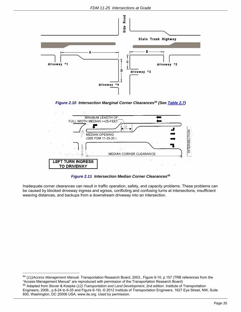
FDM 11-25 Intersections at Grade
Page 35
Figure 2.10 Intersection Marginal Corner Clearances44 (See Table 2.7)
Figure 2.11 Intersection Median Corner Clearances45
Inadequate corner clearances can result in traffic operation, safety, and capacity problems. These problems can be caused by blocked driveway ingress and egress, conflicting and confusing turns at intersections, insufficient weaving distances, and backups from a downstream driveway into an intersection.
44 (11)Access Management Manual. Transportation Research Board, 2003., Figure 9-10, p 157 (TRB references from the “Access Management Manual” are reproduced with permission of the Transportation Research Board) 45 Adapted from Stover & Koepke (12) Transportation and Land Development, 2nd edition. Institute of Transportation Engineers, 2006., p.6-24 to 6-35 and Figure 6-19). © 2012 Institute of Transportation Engineers, 1627 Eye Street, NW, Suite 600, Washington, DC 20006 USA, www.ite.org. Used by permission.
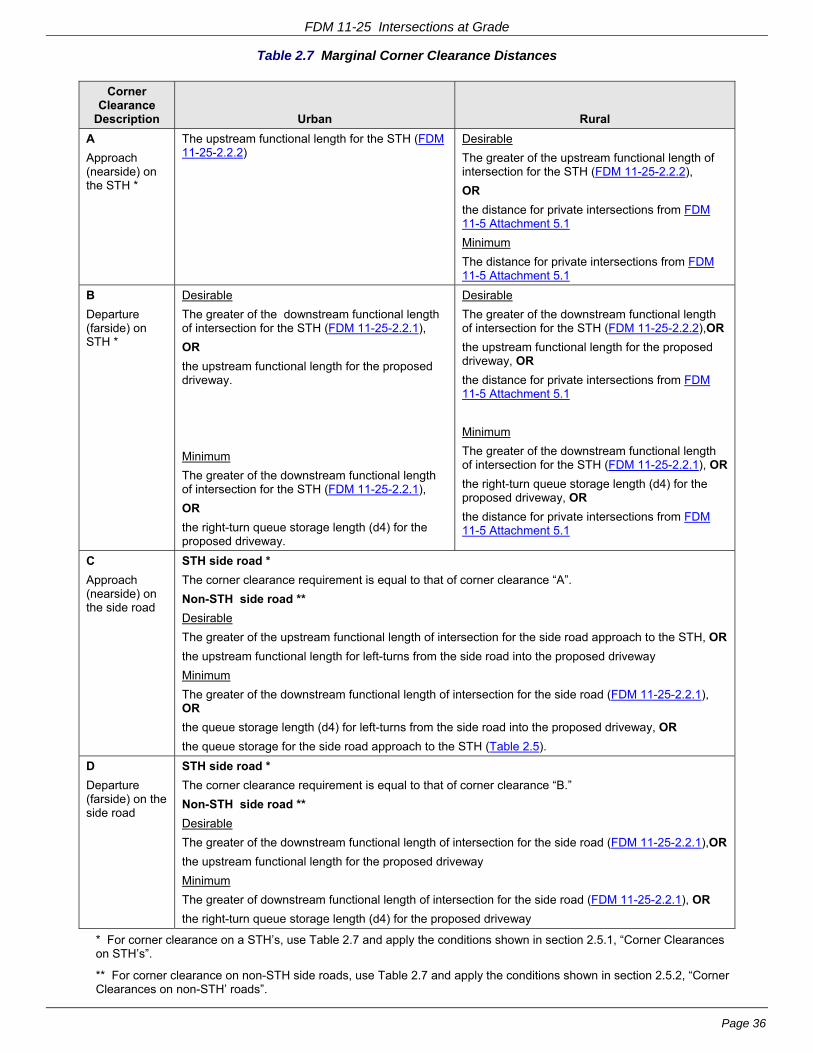
FDM 11-25 Intersections at Grade
Page 36
Table 2.7 Marginal Corner Clearance Distances
Corner Clearance
Description Urban Rural
A
Approach (nearside) on the STH *
The upstream functional length for the STH (FDM 11-25-2.2.2)
Desirable
The greater of the upstream functional length of intersection for the STH (FDM 11-25-2.2.2),
OR
the distance for private intersections from FDM 11-5 Attachment 5.1
Minimum
The distance for private intersections from FDM 11-5 Attachment 5.1
B
Departure (farside) on STH *
Desirable
The greater of the downstream functional length of intersection for the STH (FDM 11-25-2.2.1),
OR
the upstream functional length for the proposed driveway.
Minimum
The greater of the downstream functional length of intersection for the STH (FDM 11-25-2.2.1),
OR
the right-turn queue storage length (d4) for the proposed driveway.
Desirable
The greater of the downstream functional length of intersection for the STH (FDM 11-25-2.2.2),OR
the upstream functional length for the proposed driveway, OR
the distance for private intersections from FDM 11-5 Attachment 5.1
Minimum
The greater of the downstream functional length of intersection for the STH (FDM 11-25-2.2.1), OR
the right-turn queue storage length (d4) for the proposed driveway, OR
the distance for private intersections from FDM 11-5 Attachment 5.1
C
Approach (nearside) on the side road
STH side road *
The corner clearance requirement is equal to that of corner clearance “A”.
Non-STH side road **
Desirable
The greater of the upstream functional length of intersection for the side road approach to the STH, OR
the upstream functional length for left-turns from the side road into the proposed driveway
Minimum
The greater of the downstream functional length of intersection for the side road (FDM 11-25-2.2.1), OR
the queue storage length (d4) for left-turns from the side road into the proposed driveway, OR
the queue storage for the side road approach to the STH (Table 2.5).
D
Departure (farside) on the side road
STH side road *
The corner clearance requirement is equal to that of corner clearance “B.”
Non-STH side road **
Desirable
The greater of the downstream functional length of intersection for the side road (FDM 11-25-2.2.1),OR
the upstream functional length for the proposed driveway
Minimum
The greater of downstream functional length of intersection for the side road (FDM 11-25-2.2.1), OR
the right-turn queue storage length (d4) for the proposed driveway
* For corner clearance on a STH’s, use Table 2.7 and apply the conditions shown in section 2.5.1, “Corner Clearances on STH’s”.
** For corner clearance on non-STH side roads, use Table 2.7 and apply the conditions shown in section 2.5.2, “Corner Clearances on non-STH’ roads”.
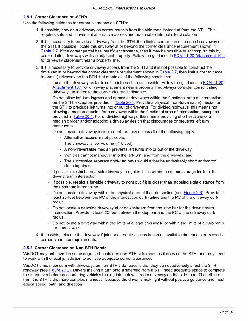
FDM 11-25 Intersections at Grade
Page 37
2.5.1 Corner Clearance on-STH's
Use the following guidance for corner clearance on STH’s:
1. If possible, provide a driveway on corner parcels from the side road instead of from the STH. This requires safe and convenient alternative access and reasonable internal site circulation
2. If it is necessary to provide a driveway from the STH, then limit a corner parcel to one (1) driveway on the STH. If possible, locate this driveway at or beyond the corner clearance requirement shown in Table 2.7. If the corner parcel has insufficient frontage, then it may be possible to accomplish this by consolidating driveways with an adjacent property. Follow the guidance in FDM 11-20 Attachment 10.1 for driveway placement near a property line.
3. If it is necessary to provide driveway access from the STH and it is not possible to construct the driveway at or beyond the corner clearance requirement shown in Table 2.7, then limit a corner parcel to one (1) driveway on the STH that meets all of the following conditions:
- Locate the driveway as far from the intersection as possible. Follow the guidance in FDM 11-20 Attachment 10.1 for driveway placement near a property line. Always consider consolidating driveways to increase the corner clearance distance.
- Do not allow left-turn ingress and egress at driveways within the functional area of intersection on the STH, except as provided in Table 20.1. Provide a physical (non-traversable) median on the STH to preclude left turns into or out of driveways. For divided highways, this means not allowing a median opening for a driveway within the functional area of intersection, except as provided in Table 20.1. For undivided highways, this means providing short sections of a median divider and/or adopting a driveway design that discourages or prevents left turn maneuvers.
- Do not locate a driveway inside a right-turn bay unless all of the following apply:
- Alternative access is not possible,
- The driveway is low-volume (<15 vpd),
- A non-traversable median prevents left turns into or out of the driveway,
- Vehicles cannot maneuver into the left-turn lane from the driveway, and
- The successive separate right-turn bays would either be undesirably short and/or too close together.
- If possible, restrict a nearside driveway to right in if it is within the queue storage limits of the downstream intersection.
- If possible, restrict a far-side driveway to right out if it is closer than stopping sight distance from the upstream intersection.
- Do not locate a driveway within the physical area of the intersection (see Figure 2.6). Provide at least 25-feet between the PC of the intersection curb radius and the PC of the driveway curb radius.
- Do not locate a nearside driveway at or downstream from the stop bar for the downstream intersection. Provide at least 25-feet between the stop bar and the PC of the driveway curb radius.
- Do not locate a driveway within the limits of a legal crosswalk, or within the limits of a curb ramp for a crosswalk.
4. If possible, relocate the driveway if joint or alternate access becomes available that meets or exceeds corner clearance requirements.
2.5.2 Corner Clearance on Non-STH Roads
WisDOT may not have the same degree of control on non-STH side roads as it does on the STH, and may need to work with the local jurisdiction to achieve adequate corner clearances.
WisDOT’s main concern with driveways on non-STH side roads is that they do not adversely affect the STH roadway (see Figure 2.12). Drivers making a turn onto a sideroad from a STH need adequate space to complete the maneuver before encountering vehicles turning into a downstream driveway on the side road. The left turn from the STH is the more complex maneuver because the driver is making it without positive guidance and must adjust speed, path, and direction

FDM 11-25 Intersections at Grade
Page 38
Figure 2.12 Inadequate Corner Clearance on Sideroad46
If it is not possible to provide the minimum corner clearance shown in Table 2.7 for a non-STH side road, then:
- Locate the driveway as far from the intersection as possible. Follow the guidance in FDM 11-20 Attachment 10.1 for driveway placement near a property line. Always consider consolidating driveways to increase the corner clearance distance.
- If possible, restrict a nearside driveway (corner clearance ‘C’) to right-in/right-out (i.e., no left-turn ingress or egress).
- If possible, restrict a far-side driveway (corner clearance ‘D’) to right-out.
- Do not locate a driveway within the physical area of the intersection (Figure 2.6). Provide at least 25-feet between the PC of the intersection curb radius and the PC of the driveway curb radius.
- Do not locate a nearside driveway at or downstream from the stop bar for the downstream intersection. Provide at least 25-feet between the stop bar and the PC of the driveway curb radius.
- Do not locate a driveway within the limits of a legal crosswalk, or within the limits of a curb ramp for a crosswalk.
2.6 Intersection Vertical Alignment
See pp.582 and 279-282 of the 2004 GDHS47.
If possible and practical, avoid grades in excess of 3% within the intersection area and on the portion of approaches where vehicles are required to stop because this complicates intersection design. Desirably, grades will be flatter than the maximum values allowed (see FDM 11-10-5.4.1 and Attachment 5.3).
On the OSOW Truck Route (OSOW-TR), check the roadway profile to avoid abrupt grade transitions that may affect OSOW-ST vehicles with low ground clearance. OSOW-ST vehicles with very low ground clearance can hang up on the roadway crown or the rollover between a superelevated section and a side road profile at intersections.
Additionally, on the OSOW-TR, some loads on OSOW-ST vehicles are susceptible to torsion or twisting forces that can exceed the torsional shear capacity of a blade, beam, or concrete member. If possible, design the vertical alignment and cross slopes in the intersection area to help avoid excessive shear forces created by torsion forces as the OSOW-ST Vehicle maneuvers the intersection.
Avoid locating intersections just beyond the crest of vertical curves.
2.7 Intersection Sight Distance
For information about intersection sight distance, refer to FDM 11-10-5.
2.8 Angle of Intersection48
It is preferable for intersecting streets to meet at an angle as close to 90°as possible. On the OSOW-TR, it is 46 Adapted from (12) Transportation and Land Development, 2nd edition. Institute of Transportation Engineers, 2006., Figure 6-20 on p. 6-30. © 2012 Institute of Transportation Engineers, 1627 Eye Street, NW, Suite 600, Washington, DC 20006 USA, www.ite.org. Used by permission. 47 (1) A Policy on Geometric Design of Highways and Streets 2004, 5th edition. AASHTO, 2004. 48 (15) Intersection Angle Geometry and the Driver's Field of View. In Transportation Research Record 1612: Highway Geometric Design Issues TRB, National Research Council, 1998, pp.10-16.,
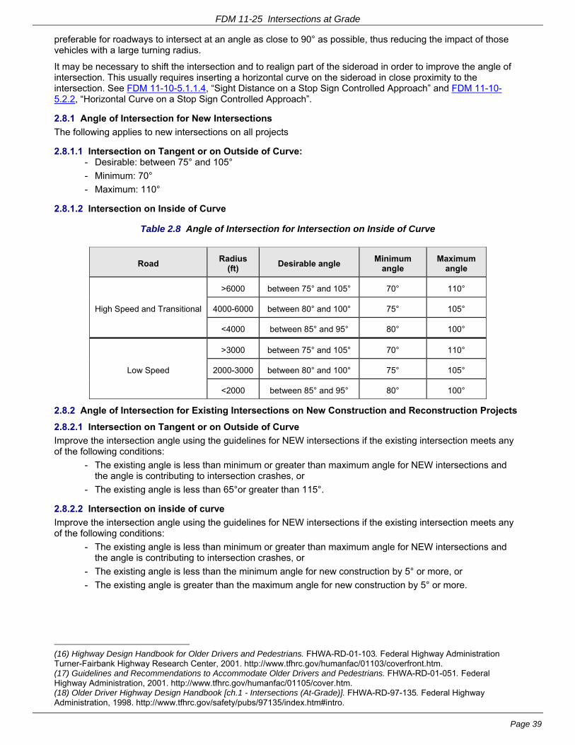
FDM 11-25 Intersections at Grade
Page 39
preferable for roadways to intersect at an angle as close to 90° as possible, thus reducing the impact of those vehicles with a large turning radius.
It may be necessary to shift the intersection and to realign part of the sideroad in order to improve the angle of intersection. This usually requires inserting a horizontal curve on the sideroad in close proximity to the intersection. See FDM 11-10-5.1.1.4, “Sight Distance on a Stop Sign Controlled Approach” and FDM 11-10-5.2.2, “Horizontal Curve on a Stop Sign Controlled Approach”.
2.8.1 Angle of Intersection for New Intersections
The following applies to new intersections on all projects
2.8.1.1 Intersection on Tangent or on Outside of Curve: - Desirable: between 75° and 105°
- Minimum: 70°
- Maximum: 110°
2.8.1.2 Intersection on Inside of Curve
Table 2.8 Angle of Intersection for Intersection on Inside of Curve
Road Radius
(ft) Desirable angle
Minimum angle
Maximum angle
High Speed and Transitional
>6000 between 75° and 105° 70° 110°
4000-6000 between 80° and 100° 75° 105°
<4000 between 85° and 95° 80° 100°
Low Speed
>3000 between 75° and 105° 70° 110°
2000-3000 between 80° and 100° 75° 105°
<2000 between 85° and 95° 80° 100°
2.8.2 Angle of Intersection for Existing Intersections on New Construction and Reconstruction Projects
2.8.2.1 Intersection on Tangent or on Outside of Curve
Improve the intersection angle using the guidelines for NEW intersections if the existing intersection meets any of the following conditions:
- The existing angle is less than minimum or greater than maximum angle for NEW intersections and the angle is contributing to intersection crashes, or
- The existing angle is less than 65°or greater than 115°.
2.8.2.2 Intersection on inside of curve
Improve the intersection angle using the guidelines for NEW intersections if the existing intersection meets any of the following conditions:
- The existing angle is less than minimum or greater than maximum angle for NEW intersections and the angle is contributing to intersection crashes, or
- The existing angle is less than the minimum angle for new construction by 5° or more, or
- The existing angle is greater than the maximum angle for new construction by 5° or more.
(16) Highway Design Handbook for Older Drivers and Pedestrians. FHWA-RD-01-103. Federal Highway Administration Turner-Fairbank Highway Research Center, 2001. http://www.tfhrc.gov/humanfac/01103/coverfront.htm. (17) Guidelines and Recommendations to Accommodate Older Drivers and Pedestrians. FHWA-RD-01-051. Federal Highway Administration, 2001. http://www.tfhrc.gov/humanfac/01105/cover.htm. (18) Older Driver Highway Design Handbook [ch.1 - Intersections (At-Grade)]. FHWA-RD-97-135. Federal Highway Administration, 1998. http://www.tfhrc.gov/safety/pubs/97135/index.htm#intro.

FDM 11-25 Intersections at Grade
Page 40
2.8.3 Angle of Intersection for Existing Intersections on 3R Projects
2.8.3.1 Intersection on Tangent or on Outside of Curve
Improve the intersection angle using the guidelines for NEW intersections if the existing intersection meets any of the following conditions:
- The existing angle is less than minimum or greater than maximum angle for NEW intersections and the angle is contributing to intersection crashes, or
- The existing angle is less than 60°or greater than 120°.
2.8.3.2 Intersection on Inside of Curve
Improve the intersection angle using the guidelines for NEW intersections if the existing intersection meets any of the following conditions:
- The existing angle is less than minimum or greater than maximum angle for NEW intersections and the angle is contributing to intersection crashes, or
- The existing angle is less than the minimum angle for new construction by 10° or more, or
- The existing angle is greater than the maximum angle for new construction by 10° or more.
2.9 Intersections on Curves
Intersections on curves of any facility are problematic and are discouraged for the following reasons:
- Drivers have more difficulty judging the speed of vehicles approaching on a curve than on a tangent.
- Superelevation complicates the intersection geometry.
- More right-of-way may be required to ensure adequate intersection sight distance (ISD), particularly on the inside of curves where the line of sight for intersection sight distance may be a considerable distance outside the roadway.
- Intersections on the inside of a curve require drivers on the side road to turn their heads more to see approaching traffic. This can be difficult for some drivers, including older drivers.
If an intersection must be on a curve, then use a flatter radius curve, if possible, and align to make the intersection as close to radial as possible. For example, on high speed roads, using a curve that requires a superelevation of 3% or less will make it easier to match into the side road profile and to transition the cross slope on auxiliary lanes. It will also keep the ISD line of sight closer to the roadway. A radial intersection in combination with a flat radius will reduce the amount drivers have to turn their heads to see approaching traffic.
Intersections on curves of high-speed (posted speed greater than 55 mph) expressways require additional design considerations. Crash history shows that there is no difference in whether the side road intersection approaches the expressway from the outside or the inside of the curve. Providing more than the minimum intersection sight distance at these intersections appears to have no impact on the number or severity of crashes. If there appears to be no alternative to designing an intersection on a curve then provide a wide median. If a wide median for intersections on curves is not possible then it is important to restrict intersection movement by closing the median or at least not allowing side road traffic to turn left onto the expressway.
2.10 References
1. A Policy on Geometric Design of Highways and Streets 2004, 5th edition. AASHTO, Washington, DC, 2004.
2. ORDOT Highway Design Manual ch. 9.0: Intersection and Interchange Design. Oregon Department of Transportation, 2008. ftp://ftp.odot.state.or.us/techserv/roadway/web_drawings/HDM/Rev_E_2003Chp09.pdf. Accessed 8-6-2010.
7. Florida Intersection Design Guide. Florida DOT, 2007. http://www.dot.state.fl.us/rddesign/FIDG-Manual/FIDG2007.pdf. Accessed 8-6-2010.
8. MADOT Highway Department Project Development & Design Guide ch. 6: Intersection Design. Massachusetts Department of Transportation - Highway Division, 2006. http://www.mhd.state.ma.us/downloads/designGuide/CH_6_a.pdf. Accessed 7-27-2010.
9. ILDOT Bureau of Design and Environment Manual ch. 36: Intersections. Illinois DOT, 2002. http://www.dot.state.il.us/desenv/BDE%20Manual/BDE/pdf/chap36.pdf. Accessed 1-8-2010.
10. NYSDOT Highway Design Manual ch. 5: Basic Design. New York State DOT, Albany, NY, 2006. https://www.nysdot.gov/portal/page/portal/divisions/engineering/design/dqab/hdm/hdm-repository/chapt_05.pdf. Accessed 8-6-2010.

FDM 11-25 Intersections at Grade
Page 41
11. TRB Committee on Access Management (ed.) (ed.). Access Management Manual. Transportation Research Board, Washington, DC, 2003. 49
12. Stover, V. G. and F. J. Koepke. Transportation and Land Development, 2nd edition. Institute of Transportation Engineers, Washington, DC, 2006. 50
13. Bonneson, J. A. and M. D. Fontaine. NCHRP Report 457: Engineering Study Guide for Evaluating Intersection Improvements. TRB, National Research Council, Washington, DC, 2001. http://onlinepubs.trb.org/onlinepubs/nchrp/esg/esg.pdf.
14. Manual on Uniform Traffic Control Devices. Federal Highway Administration, Washington, DC, 2009.
15. Gattis, J. L. and S. T. Low. Intersection Angle Geometry and the Driver's Field of View. In Transportation Research Record 1612: Highway Geometric Design Issues. TRB, National Research Council, Washington, DC, 1998, pp. 10-16.
16. Staplin, L. K., K. Lococo, S. R. Byington, and Scientex Corporation. Highway Design Handbook for Older Drivers and Pedestrians. FHWA-RD-01-103. Federal Highway Administration Turner-Fairbank Highway Research Center, McClean, VA, May, 2001. http://www.tfhrc.gov/humanfac/01103/coverfront.htm. Accessed 4-2-2009.
17. Staplin, L., K. Lococo, S. Byington, D. Harkey, and FHWA. Guidelines and Recommendations to Accommodate Older Drivers and Pedestrians. FHWA-RD-01-051. Federal Highway Administration, McLean, VA, May, 2001. http://www.tfhrc.gov/humanfac/01105/cover.htm. Accessed 3-16-2006.
18. Staplin, L., K. Lococo, and S. Byington. Older Driver Highway Design Handbook [ch.1 - Intersections (At-Grade)]. FHWA-RD-97-135. Federal Highway Administration, Washington, DC, Jan., 1998. http://www.tfhrc.gov/safety/pubs/97135/index.htm#intro. Accessed 2-3-2009.
LIST OF ATTACHMENTS
Attachment 2.1 WisDOT Vehicle Inventory of Oversized Overweight (OSOW) Vehicles
Attachment 2.2 WisDOT Interim Policy on Checking Criteria for OSOW-ST and OSOW-MT Vehicles at Intersections
Attachment 2.3 Taper Length Criteria
FDM 11-25-3 Intersection Control Evaluation January 13, 2017
3.1 Intersection Control Evaluation (ICE)
In order to address traffic operations and safety concerns (existing or design year), it may be beneficial to consider different traffic control options (e.g., no-control, yield-control, stop-control or signal-control) and intersection/interchange types (e.g., roundabout, reduced conflict intersection, diamond interchange, etc.). The selection of the most appropriate alternative requires engineering judgment. To document the various discussions and decisions made during the selection of the preferred traffic control and intersection/interchange type, the region shall follow the Intersection Control Evaluation (ICE) process. Through this documentation, the ICE process provides justification and support for the intersection/interchange design decisions made through the course of a project, which can prove beneficial in the event WisDOT faces public and/or legal challenges.
The purpose of the ICE process is to document the analysis (technical and financial), political concerns and public feedback used to assess the potential advantages, disadvantages, and feasibility associated with the various traffic control alternatives. The ICE assists the Department with determining the preferred traffic control and/or intersection/interchange type in a consistent and defensible manner. The goal is to select the optimal control, lane configuration, geometry and type of intersection/interchange based on an objective analysis of the existing conditions and future needs.
49 [Aug 17, 2004 email from Javy Awan, Director of Publications, Transportation Research Board] TRB references are reproduced with permission of the Transportation Research Board, From Access Management Manual, Transportation Research Board, National Research Council, Washington, D.C., 2003 50 [Dec 5, 2012 email and attached letter from Zach Pleasant, Information Services Director, ITE] The Institute of Transportation Engineers grants permission to use Figures 6-19, P6-27 and 6-20, P6-30 from Transportation and Land Development, 2nd Edition for the Wisconsin DOT’s Facilities Development Manual (FDM 11-25). Please know that this is a one-time, one-use agreement, and any other use of this material or any other resource of ITE must be requested and approved in writing. Please acknowledge our copyright by publishing: © 2012 Institute of Transportation Engineers, 1627 Eye Street, NW, Suite 600, Washington, DC 20006 USA, www.ite.org. Used by permission.
FDM 11-25 Intersections at Grade
Page 42
Either large corridor studies or smaller intersection-specific (safety- or capacity-driven) improvement projects can trigger the need for completion of the ICE process. For intersection-specific projects, the identified need to evaluate alternative traffic control or intersection/interchange type is usually the major component of the project. Thus, the ICE process will have a significant impact in the overall development of the project. In contrast, the project purpose, need and scope associated with a larger corridor study often dictate the feasible options evaluated in the ICE study. In these cases, the ICE process may be a small component of the overall development of the project. Both these scenarios illustrate the importance of completing the ICE process during the appropriate time in the facilities development process in order to ensure that the project proceeds smoothly. Attachment 3.1 illustrates how the ICE process relates to the overall facilities development process. Attachment 3.2 highlights the key steps of the ICE process.
3.1.1 ICE Project Triggers
The region shall perform an ICE study for all intersections on the State Trunk Network (STN), regardless of the funding mechanism, and for all projects designed and/or constructed with federal or state funding (whether on the STN or not) where consideration is being given to an alternative form of traffic control or type of intersection/interchange. Situations that generally trigger the need for an ICE study include, but are not limited to, the following:
- New traffic control
- A change in traffic control
- A new or alternative type of intersection or interchange (e.g., reduced conflict intersection/interchange)
- Introduction of access/median restrictions on the STN (e.g., converting a full access intersection to right-in-right-out only)
- Off-setting intersections (e.g., converting one 4-legged intersection into two T-intersections)
These scenarios typically arise through means of the highway improvement program, the highway maintenance program and/or the highway permitting process. This can include, but is not limited to, projects identified and/or funded through the following programs or processes:
- Mega/Major Highway Development Program
- State Highway Rehabilitation Program (3R, 4R)
- State Transportation Program (STP)
- Congestion Mitigation and Air Quality Program (CMAQ)
- Safe Routes to School Program (SRTS)
- Local Roads Improvement Program (LRIP)
- Transportation Economic Assistance Program (TEA)
- Highway Safety Improvement Program (HSIP)
- Traffic Impact Analysis (TIA)
The ICE process is the same for projects identified by WisDOT, counties, municipalities, or local units of government that are interested in receiving federal or state funds through any of the programs identified above.
3.1.1.1 Traffic Impact Analysis and ICE
A TIA, although not an actual highway improvement or maintenance project, is part of the highway permitting process and provides a means to assess traffic impacts due to a development. If the TIA finds that a development has an impact at an intersection along the STN, it will provide recommendations for how the developer can mitigate the potential impact. This could include recommendations for an alternative form of traffic control or type of intersection. Since the TIA develops recommendations for improvements to the traffic control at intersections located on the STN it shall comply with the ICE process. For ICE guidance as it relates to a TIA, see the TIA Guidelines, Chapter 5 Part F - Traffic Control Needs (http://wisconsindot.gov/dtsdManuals/traffic-ops/manuals-and-standards/tiaguide.pdf).
3.1.2 ICE Process Exemptions
Although all projects designed and constructed with federal or state funds shall comply with the ICE process, the level of analysis required varies depending on the specifics of the project. Some situations may only require a brief scoping level assessment and others may require a detailed level of analysis. (See FDM 11-25-3.2 for specifics regarding the ICE process and the different levels of analysis.) Additionally, there are a few exceptions where the completion of an ICE is not necessary. These exceptions include the following scenarios:
- There are no operational or safety concerns (existing or future) – in this case the existing intersection traffic control can be replaced in kind as part of a resurfacing project without triggering the need for an ICE

FDM 11-25 Intersections at Grade
Page 43
- Introduction of stop control on the minor street (one-way or two-way stop-control) if the minor street is not part of the STN – this scenario introduces the least restrictive form of traffic control on the STN and thus generally does not warrant the completion of an ICE
- Proposing only minor improvements to the intersection (e.g., adding turn lanes or modifying signal phasing) – unless access restrictions or alternative forms of traffic control are also being considered, this scenario will generally not require the completion of an ICE
- Addition of new pedestrian signals at mid-block locations - since this scenario does not impact the intersection, an ICE is not necessary
Please contact the Bureau of Traffic Operations (BTO) -Traffic Analysis and Safety Unit (TASU) for additional clarification as to when the completion of an ICE study is or is not required.
3.1.3 Guidance and Criteria for Traffic Control Options and Intersection/Interchange Types
Stop sign control, signal control, roundabout and reduced conflict intersection/interchange designs are common types of traffic control and intersection/interchange layouts. Attachment 3.3 highlights the key elements to consider when selecting each type of intersection; interchange and traffic control option; and identifies some of the potential benefits and concerns for each option. Additional details on these intersection/interchange types and traffic control options follow.
1. Stop Sign Control
Stop-sign controlled intersections consist of one-way, two-way or all-way stop control (OWSC, TWSC or AWSC)51. The OWSC or TWSC control is most common and requires traffic to stop on the minor road connection(s) to a major highway. Typically, OWSC or TWSC control is the existing traffic control alternative in the ICE study. An ICE is generally not required when OWSC or TWSC is the recommended traffic control for a new intersection.
The use of AWSC on the STN is generally not recommended; however, if AWSC-warrants are met and the addition of AWSC will improve intersection safety, AWSC may be a viable traffic control alternative, especially as an interim solution. Refer to Chapter 13, Section 26-5 of the Traffic Engineering Operations and Safety Manual (TEOpS 13-26-5) for AWSC criteria that considers both WisDOT and MUTCD policies. Utilize the AWSC warrant spreadsheet located in TEOpS 13-26 to assess whether there is justification for the installation of AWSC.
2. Signal Control
Traffic signal warrants are the guiding principle for when to consider the installation of a traffic signal. See MUTCD - Section 4C and the Traffic Signal Design Manual (TSDM) Chapter 2 (http://wisconsindot.gov/Pages/doing-bus/local-gov/traffic-ops/manuals-and-standards/tsdm/02.aspx) for traffic signal warrants (TSDM 2-3). Also, see the TSDM for design, capacity and operational guidance for signal control.
The region shall complete the ICE process and the State Traffic Signal Systems Engineer shall approve the new installation of a traffic signal along all state trunk highways and connecting highways. New pedestrian signals at mid-block locations also require approval from the State Traffic Signal Systems Engineer; however, these locations would not trigger the need for an ICE. After completion of the ICE process, the region traffic section shall submit the Traffic Control Signal Approval Request form (DT1199) to the State Traffic Signal Systems Engineer for review. Completion of the ICE process and submittal of the DT1199 are required prior to making any commitments concerning the installation of new traffic signal control.
3. Roundabout
Consider the modern roundabout as a traffic control alternative when the minimum vehicular volume warrants for either all-way stop control or traffic signal control are met. There may also be situations where it is appropriate to consider a roundabout where an intersection has unique safety (e.g., significant right-angle crashes, limited intersection sight distance, etc.) or geometric concerns (e.g., skewed intersection, 5 plus approaches, etc.).
Careful consideration and coordination among region traffic engineers and designers as well as local entities must be part of the project development process when considering a roundabout and the proposed roundabout design. Refer to (NCHRP Report 672 (Second Edition) Section 3.3 (http://onlinepubs.trb.org/onlinepubs/nchrp/nchrp_rpt_672.pdf)) for considerations in selecting a
51 One-Way Stop Control (OWSC) applies to Tee-Intersections; Two-way Stop Control (TWSC) applies to 4-legged intersections

FDM 11-25 Intersections at Grade
Page 44
roundabout as an alternative. Refer to FDM 11-26 for design and operational guidance on roundabouts.
The acceptance of three-lane roundabouts is up to the discretion of the region. However, if the region’s recommendation is to construct a three-lane roundabout, the BTO State Traffic Engineer and Bureau of Project Development (BPD) Roadway Standards Chief shall approve the roundabout as the recommended traffic control alternative.
4. Reduced-Conflict Intersections/Interchanges
Traffic engineers and designers have additional options in intersection/interchange types that combined with traffic control may be appropriate for a given situation. These designs may have advantages over traditional intersection and interchange types, depending on the existing and future safety and operational concerns.
Some of the reduced-conflict intersection/interchange types are adaptable for only one type of traffic control. In these cases, it is still possible to compare alternative intersection control types but intersection geometry may be different for each control type. The ICE could also compare different intersection/interchange types with the same traffic control. For some reduced-conflict intersections/interchanges, microsimulation may be necessary to supplement the HCM-based analysis. Refer to FDM 11-5-3.7 for a description of the supported microsimulation software and their appropriate use.
The Department recognizes the evolving-nature of design and analysis standards for reduced-conflict intersections and interchanges, but this should not discourage the selection of these types of designs as the recommended alternative. The expected future demands on many facilities, as well as the benefits reduced conflict intersections and interchanges may bring for a particular location, could favor the implementation of these types of intersections or interchanges types. Consider the reduced-conflict intersection and interchange types listed in Attachment 3.3, as well as other innovative design concepts, as applicable during the ICE process.
The region shall facilitate an independent peer review of the design for all proposed reduced-conflict interchanges prior to making any commitments towards the construction of the new interchange design.
3.2 ICE Process
The ICE study shall be prepared by, or under the supervision of, a professional engineer, registered in Wisconsin, with experience in traffic engineering. Either the region or a consultant, through coordination with the region, may complete the ICE.
The ICE process consists of two phases.
1. Phase I: Scoping ICE
The region shall complete the Phase I: Scoping ICE early in the project development process - prior to the Project Resourcing Phase. (See Attachment 3.1 for an illustration of how the Phase I: Scoping ICE relates to the facilities development process). The purpose of the Phase I: Scoping ICE is to identify all possible traffic control alternatives and recommend those alternatives to carry forward for further evaluation in the Phase II: Alternative Selection ICE. If the Phase I: ICE identifies only one viable alternative, there is no need to proceed with the Phase II: ICE.
The region shall prepare a memorandum during this phase that summarizes all potential alternatives considered, defines which of the alternatives are feasible or infeasible and documents the process for determining this feasibility. The region shall complete the Phase I: ICE memorandum prior to obtaining public input (Attachment 3.4). To assist with defining the feasible alternatives, the region should complete the Phase I: ICE Brainstorming Guide (Attachment 3.5). Please expand upon the list of traffic control alternatives provided within the guide as appropriate.
The region shall submit the Phase I: Scoping ICE memorandum (Attachment 3.4), and if completed the Phase I: ICE Brainstorming Guide (Attachment 3.5), to BTO via the DOT ICE Review mailbox ([email protected]) for review prior to proceeding to the Phase II: ICE.
2. Phase II: Alternative Selection ICE
The Phase II: Alternative Selection ICE involves a more detailed evaluation of the feasible alternatives identified in the scoping phase. Completion of the Phase II: ICE generally occurs during the Preliminary Impact Review phase of the facilities development process. (See Attachment 3.1 for an illustration of how the Phase II: Alternative Selection ICE relates to the facilities development process).

FDM 11-25 Intersections at Grade
Page 45
The purpose of the Phase II: ICE is to assist the Department in selecting a traffic control, lane configuration and intersection/interchange type for the studied location. The region shall prepare, or contract with a consultant to prepare, the ICE study to summarize the findings of the detailed analysis and complete the Phase II: ICE worksheet (Attachment 3.6). Prior to completion of the Phase II: ICE and selection of the recommended alternative, the region shall solicit feedback from the public regarding the feasible alternatives.
The region shall submit the Phase II: ICE worksheet to BTO via the DOT ICE Review mailbox ([email protected]) for review prior to final selection of the recommended alternative.
3.2.1 Phase I: Scoping ICE
All projects that trigger the need to follow the ICE process shall complete the Phase I: Scoping ICE prior to proceeding with the Phase II: Alternative Selection ICE. The Phase I: Scoping ICE typically consists of a short memorandum (may be as short as one page) which documents all possible intersection types and/or traffic control alternatives considered. See Attachment 3.4 for a template of the Phase I: ICE memorandum.
To assess the feasibility of various alternatives, the region should use the Phase I: ICE Brainstorming Guide (Attachment 3.5). Expand upon the list of traffic control alternatives provided within the guide as appropriate. If completed, reference the Phase I: ICE Brainstorming Guide (Attachment 3.5), as applicable within the Phase I: ICE memorandum to identify those alternatives considered but immediately dismissed from consideration.
The Phase I: ICE memorandum shall provide justification as to why each alternative is or is not feasible and should recommend those alternatives to carry forward for further evaluation in the Phase II: Alternative Selection ICE. If the Phase I: ICE identifies only one viable alternative, there is no need to proceed with the Phase II: ICE.
The specific content of the Phase I: ICE memorandum will vary depending on the project’s location, scope and the available data (e.g., a project in the early scoping stages may not yet have traffic count data while a project further along in the development process may have existing and forecasted turning movement counts). The Phase I: Scoping ICE shall provide the following information:
- Project Description
- Description of Alternatives
- Safety Considerations
- Operational Considerations
- Other Considerations
- Feasibility of Alternatives
- Conclusions/Recommendations
The discussion that follows provides details regarding the specific content to include under each of the above-mentioned topics. Although it is acceptable for the Phase I: Scoping ICE to include additional information other than that listed above, exercise caution when it comes to providing additional analysis. It is important not to overanalyze any of the alternatives in the scoping phase, as it is possible to eliminate some alternatives from consideration without going into detailed analysis.
Refer to Attachment 3.4 for a checklist of the required and optional items to include with submittal of the Phase I: Scoping ICE memorandum. This checklist should serve as a guide only and does not need to be included with the submittal of the Phase I: ICE. Please contact BTO via the DOT ICE Review mailbox ([email protected]) for specific examples of what to include in the Phase I: ICE memorandum.
3.2.1.1 Project Description
Provide a brief description of the project background, the need for the project (i.e., operational and/or safety), the scope of the project, the project type (HSIP, SRTS, etc.) and a summary of the existing conditions of the intersection and surrounding area.
3.2.1.2 Description of Alternatives
List all alternatives taken into consideration (no matter how briefly) and provide a brief description of each of the analyzed alternatives. If completed, refer to and attach the Phase I: ICE Brainstorming Guide (Attachment 3.5) as appropriate to discuss those alternatives immediately eliminated from consideration.
3.2.1.3 Safety Considerations
At a minimum, this section shall include a qualitative discussion on the existing and/or anticipated safety concerns at the intersection. For example, a discussion on any sight distance issues or significant skew of the intersection could illustrate potential safety concerns. See Table 1.1 for a list of potential intersection safety treatments.

FDM 11-25 Intersections at Grade
Page 46
This section should include a summary of the number, type and severity of crashes based on the same 5 years of crash data used for the project. Preliminary crash data may be acceptable as supplemental information, but should not count as one of the 5 years of analysis data. This information is available through the Wisconsin Traffic Operations and Safety Laboratory (TOPS Lab) WisTransPortal (http://transportal.cee.wisc.edu/services/crash-data/). Access to the WisTransPortal requires a user account.
If available, provide a crash diagram and intersection crash rate for the influence area of the intersection as an attachment to the Phase I: ICE memorandum. Although not a required element, a crash diagram should accompany the submittal of the Phase I: ICE, especially if safety is the primary factor for considering an alternative form of traffic control. Please note that although the crash rate provides additional information regarding the intersection safety, it is not the sole indicator of the presence or lack of a safety concern.
3.2.1.4 Operational Considerations
At a minimum, this section should provide a qualitative discussion on the existing and future operational and/or capacity concerns. Field surveys or photographs taken during the peak periods are some ways to demonstrate capacity concerns if the data needed for detailed operational analysis is not available. Average annual daily traffic volumes (AADT), which are available through the coverage count program (http://wisconsindot.gov/Pages/projects/data-plan/traf-counts/default.aspx), can also provide insight into potential capacity concerns. Consideration should be given to all modes of transportation (passenger vehicles, bicycles, pedestrians, freight, etc.) when assessing the operational and/or capacity concerns.
Ideally, the Phase I: ICE memorandum should provide a summary of the quantitative capacity analysis conducted using the methodologies from the most recent version of the Highway Capacity Manual (HCM). Refer to FDM 11-5-3 for details on the traffic analysis methodologies and analysis tools to use when conducting the quantitative capacity analysis. If the Phase I: ICE incorporates quantitative capacity analysis, the region shall conduct a peer review of the traffic analyses in accordance with the procedures outlined in the Traffic Engineering Operations and Safety Manual (TEOpS) TEOpS 16-25. In most cases, the peer review will consist of a region-level review of the analysis.
If the alternative consists of restricting access (e.g., right-in/right-out only, J-Turn, etc.), a detailed operational analysis of the study intersection may not be necessary. However, the Phase I: ICE memorandum should provide an assessment (qualitative or quantitative) of the potential impacts to any nearby intersections (e.g., restricting the study intersection to right-in/right-out may add traffic to a nearby intersection and the ICE should document if the nearby intersection can accommodate the additional traffic).
Data permitting, conduct all-way stop-control and traffic signal warrants when considering the addition of new AWSC, roundabout or traffic signal control as a possible traffic control alternative. Summarize the findings of the warrant analysis within the Phase I: ICE memorandum and attach a copy of the warrant worksheets. If the data is not available to conduct the warrant analysis, provide a qualitative assessment as to whether AWSC, roundabout, or signal control should remain a viable alternative for further evaluation.
3.2.1.5 Other Considerations
Provide a brief description of any other factors taken into consideration during the Phase I: ICE analysis. Additional factors could include overall corridor and geometric considerations, pedestrian/bicycle facilities, oversize-overweight (OSOW) routes, potential environmental issues, right-of-way concerns, expected costs for each alternative, coordination with local government and any other important consideration that may be unique to the project or location.
For a scoping level assessment of real estate impacts, it is important to note that in some cases, an HCM based capacity analysis is not necessary. For example, when considering a roundabout during scoping, use the guidance in FDM 11-26-20.2.1 (which describes a simple method to estimate the need for single or multi-lane entries and circulating lanes) to estimate the size of the roundabout. Then, as described in FDM 11-26-20.2.1, use the typical inscribed circle diameter estimates to determine the space requirements of a roundabout and to assess the right of way/real estate impacts.
3.2.1.6 Feasibility of Alternatives
Highlight the advantages and disadvantages of each alternative. Clearly identify and justify whether each alternative is feasible or not. Some scenarios that may justify the elimination of an alternative from further consideration include, but are not limited to, the following:
- The intersection is part of a signal corridor and an alternative traffic control would disrupt traffic flow
- The intersection requires railroad preemption as determined by WisDOT Bureau of Transit, Local Roads, Railroads and Harbors (BTLRRH) and BTO, which may make unsignalized traffic control options undesirable

FDM 11-25 Intersections at Grade
Page 47
- Right-of-way, environmental or cost impacts of the alternative under consideration have far greater adverse impacts when compared to other intersection control alternatives
If the region requires assistance in determining if a traffic control alternative requires further evaluation in the Phase II: Alternative Selection ICE, consult with BTO.
3.2.1.7 Conclusions
Summarize the findings of the analysis, document the process followed to evaluate the alternatives, and recommend the viable alternatives to carry forward for further evaluation in the Phase II: Alternative Selection ICE. If there is only one feasible alternative, there is no need to proceed with the Phase II: ICE.
The region shall submit the Phase I: ICE memorandum and, if completed, the Phase I: ICE Brainstorming Guide (Attachment 3.5) to BTO via the DOT ICE Review mailbox ([email protected]) for review prior to proceeding with the Phase II: ICE. Document the findings in the project file and share the data and memorandum with WisDOT’s project development team.
The Phase I: ICE memorandum findings are valid for three years. If the region does not initiate the Phase II: Alternative Selection ICE or the project has not entered the Preliminary Impact Review phase within three years after completion of the Phase I: Scoping ICE, the region shall reassess the findings of the Phase I: ICE memorandum. A reassessment of the Phase I: Scoping ICE is necessary to ensure that changes in traffic volumes or other traffic conditions do not alter the recommendations. If the conclusions of the original Phase I: Scoping ICE are still valid, the region does not need to update the Phase I: ICE. However, if changes in traffic volumes or other traffic conditions alter the findings of the study, the region should update the Phase I: ICE memorandum and resubmit to BTO for review. Please consult with BTO to verify the extent of the revisions needed and/or the need to update the Phase I: Scoping ICE.
3.2.2 Phase II: Alternative Selection ICE
The Phase II: Alternative Selection ICE provides additional, in-depth analysis of the feasible alternatives identified during the Phase I: Scoping ICE. As such, the region shall not complete the Phase II: Alternative Selection ICE until after BTO’s review of the Phase I: ICE memorandum. The region shall prepare or contract with a consultant to conduct the analysis required for the Phase II: ICE. At a minimum, the Phase II: ICE should provide an assessment of the following factors (listed in no particular order):
- Practical Feasibility
- Operational Analysis
- Safety
- Pedestrians and Bicycles
- OSOW Freight Network
- Right-of-Way Impacts
- Environmental Impacts
- Costs
The region shall address each of these factors for all feasible alternatives and document the findings within the Phase II: ICE worksheet illustrated in Attachment 3.6. The Phase II: ICE worksheet provides a summary of all the general information, which is the same for all traffic control alternatives, at the beginning of the worksheet and any specific details, which are unique to the traffic control alternative, at the end of the worksheet. Please contact BTO - TASU prior to completing a separate technical report or memorandum for the Phase II: ICE, as in most cases the Phase II: ICE worksheet should sufficiently capture all of the necessary details of the analysis. The region shall submit the Phase II: ICE worksheet and supporting analysis to BTO via the DOT ICE Review mailbox ([email protected]) for review prior to final selection of the recommended alternative.
The discussion that follows provides details regarding the specific content to include under each section of the Phase II: ICE worksheet. Refer to Attachment 3.7 for a checklist of the required and optional items to include with submittal of the Phase II: Alternative Selection ICE. This checklist should serve as a guide only and does not need to be included with the submittal to BTO. For specific examples of a Phase II: Alternative Selection ICE, please contact BTO via the DOT ICE Review mailbox ([email protected]).
3.2.2.1 Project and Analyst Information
In this section, provide the project identification number, name and agency of the analyst, and the completion date of the analysis. Use the drop-down list to select the project type or funding source for the project (e.g., HSIP, SRTS, etc.) and briefly describe the location of the project.
FDM 11-25 Intersections at Grade
Page 48
3.2.2.2 Background Information
In this section, identify the primary need for the project (e.g., safety concerns, operational issues, etc.). Provide a brief description of the project background information including the scope of the project, previous work associated with the subject intersection/interchange and a summary of the existing conditions of the intersection or interchange and surrounding area. Identify whether the intersection/interchange improvements are part of a larger corridor study. Additionally, note any local constraints or considerations that could potentially affect the alternative selection.
3.2.2.3 Existing Crash Information
In this section, using the same 5-years of crash data used for the project, complete the table to identify the number of crashes by crash type and crash severity. Preliminary crash data may be acceptable as supplemental information, but should not count as one of the 5 years of analysis data. This information is available through the Wisconsin Traffic Operations and Safety Laboratory (TOPS Lab) WisTransPortal (http://transportal.cee.wisc.edu/services/crash-data/). Access to the WisTransPortal requires a user account.
Identify the analysis years (e.g., 2010-2014) for the crash information and calculate the intersection crash rate. Provide a summary of any crash trends. Include a crash diagram of the intersection as an attachment to the Phase II: ICE worksheet (Attachment 3.6). Please note that although the crash rate provides additional information regarding the intersection safety, it is not the sole indicator of the presence or lack of a safety concern.
3.2.2.4 Additional Modes of Transportation
This section provides an overview of the pedestrian, bicycle, OSOW or other modes of transportation, including horse-and-buggy, to consider during evaluation of each alternative. Complete the table to identify whether there are any nearby generators for each mode of transportation identified (e.g., bike trail, transit stop, a large distribution facility, Amish community, etc.). Indicate whether the intersection is part of a Safe-Route-to-School (SRTS) or is part of the bicycle network. This information is available through review of comprehensive land use plans, Wisconsin bike maps, OSOW permitting history and other planning documents.
Approximate, and note in the table as appropriate, the existing magnitude of each mode of transportation (e.g., number of OSOW vehicles per year, number of pedestrians/bicycles at the intersection during the peak period, etc.). Existing pedestrian and bicycle count data is generally included as part of the overall intersection turning movement count.
Use the space below the table to elaborate on any specific concerns or limitations a specific mode of transportation may have on the alternative selection and/or intersection design. Identify any plans to construct additional facilities to accommodate the alternative mode(s) of transportation within, or near, the project limits and note whether these plans are dependent on the alternative selection.
All alternatives shall comply with the American with Disabilities Act (ADA) rules and regulations for pedestrian and bicycle facilities.
3.2.2.5 Summary Table
This section provides a quick overview of each of the traffic control alternatives under consideration. Identify the traffic control associated with each alternative. Briefly describe any geometric changes (e.g., addition of a left turn lane, etc.) to be completed in conjunction with the specific traffic control alternative. Fill out the appropriate table columns to identify the total construction and operation/maintenance costs for each alternative, and briefly note the extent of any real estate, right-of-way and/or environmental impacts. Provide detailed cost estimates and a conceptual drawing of the proposed alternative as an attachment to the Phase II: ICE worksheet (Attachment 3.6).
3.2.2.6 Recommendation
In this section, identify the preferred/recommended alternative and provide justification for the recommendation (e.g., explain why one alternative is superior to the others). Document any unique considerations, concerns or other factors that influenced the selection of the recommended alternative.
3.2.2.7 Practical Feasibility
This section highlights the practical feasibility of each traffic control alternative. Common factors that influence the practical feasibility include, but are not limited to, the following:
- Public Opinion - Summarize feedback received from the public information meetings (PIMs) as well as any other comments/opinions from local officials, businesses, and the general public.
- Business Impacts - List major potential impacts to businesses, including access restrictions and parking availability.

FDM 11-25 Intersections at Grade
Page 49
- Right-of-Way (ROW) Impacts - List the type of land use (residential, business, etc.) and amount of right-of-way acquisition required. Identify the number of relocations, by land use category, required for each alternative. Provide a map/diagram illustrating the ROW impacts.
- Utility Impacts - Identify the extent of any additional utility needs or utility relocations required for each alternative.
- Cost Estimate - Provide a summary of the factors that influenced the cost estimates (construction costs, operation/maintenance costs and right-of-way/real estate costs) provided in the summary table section of the worksheet.
- Additional Considerations - List any other considerations, such as geometric constraints, OSOW, pedestrian/bicycle facilities or accommodation of other modes of transportation that influence the practical feasibility of the alternative. Note whether the intersection is part of a diversion route, a signalized corridor, or larger corridor study, and the implications this may have on the design (e.g., alternative selection, design vehicle, lane configuration, etc.). Additionally, identify if there are any major historical, archeological, hazardous materials or other environmental or unique impacts that effect the practical feasibility of the alternative.
3.2.2.8 Operational Analysis
In this section, provide a brief summary of the key operational and capacity considerations associated with each traffic control alternative. Specifically, this section should address the following:
- Warrant Analysis Results – Conduct the all-way stop-control and traffic signal warrant analysis, as appropriate, for each alternative (see FDM 11-25-3.1.3 for more information as to when a warrant analysis is required). Please note that both the AWSC and traffic signal warrant analyses are required for consideration of a new roundabout. Summarize the results of the warrant analyses here (e.g., satisfies signal warrants 1 and 2, etc.) and attach copies of the warrant analyses worksheets as an appendix to the Phase II: ICE worksheet.
- Queue Impacts – Based on the 95th-percentile back-of-queue length, assess whether the existing and/or future queues will block access to a left or right turn lane, a driveway, another intersection, a railroad crossing, a lift bridge, or any other critical location. Note how the queuing affects the intersection design (e.g., turn bay lengths) and/or alternative selection.
- Additional Capacity – Conduct a sensitivity analysis to assess how much additional capacity above the design-year traffic volumes (if any) each traffic control alternative can accommodate. If the intersection is located on a route that is parallel to a freeway, consider the ability to accommodate 5 to 20 percent additional traffic due to diversion because of an incident on the freeway. Summarize the findings of the sensitivity analysis here.
- Railroad/Lift Bridge Influences – Identify the location of any railroad crossings and/or lift bridges that may affect the operations of the intersection. Note whether the spacing between the intersection and the railroad crossing/lift bridge favors or precludes an alternative from consideration. Indicate whether any special design features (e.g., signal coordination, railroad preemption, etc.) are necessary to support the traffic control alternative.
- Additional Considerations – Identify any other factors that could potentially influence (either positively or negatively) the intersection capacity or operation. These additional considerations include, but are not limited to, high seasonal traffic variations, nearby special generators, approach angles and/or grades, sight distance concerns, access management control, elderly population, and the ability to accommodate U-turn movements. Additionally, use this section to note any unique input features into or findings from the operational analysis (e.g., use of HCM 2000 results) for each alternative.
- Level of Service (LOS) Analysis – Use the methodologies outlined in the most recent version of the Highway Capacity Manual (HCM) to conduct the level of service (i.e., capacity) analysis for existing and design year traffic conditions. Refer to FDM 11-5-3 for details on the traffic analysis methodologies and analysis tools to use when conducting the quantitative capacity analysis. The region shall conduct a peer review of all traffic analyses provided in the Phase II: Alternative Selection ICE, as outlined in the Traffic Engineering Operations and Safety Manual TEOpS 16-25. Unless the analysis involves microsimulation models, the peer review will generally consist of a region-level review (i.e., typically the review can be done in-house without the need to involve an outside consultant). To assist the region with the peer review, the analyst shall provide the region with a digital copy of the traffic analysis files (e.g., HCS, Synchro, Sidra).
- Upon completion of the level of service analysis, fill out the tables indicating the analysis year, lane configurations, LOS, delay, volume-to-capacity ratio (v/c), 95th percentile queue length and the available storage/turn bay length for each movement. For AWSC, roundabout, and signalized control, note the overall intersection LOS. Provide copies of the LOS analysis worksheets as an attachment to

FDM 11-25 Intersections at Grade
Page 50
the Phase II: ICE worksheet (Attachment 3.6).
3.2.2.9 Safety
This section should highlight the potential safety performance for each traffic control alternative. Crash Modification Factors (CMFs) help quantify the potential safety benefits of proposed changes to traffic control, intersection geometrics or other safety countermeasures. WisDOT has developed a table of recommended CMF values for different safety treatments and traffic control changes (refer to http://wisconsindot.gov/dtsdManuals/traffic-ops/manuals-and-standards/teops/cmf-table.xlsm). Refer to TEOpS 12-3-1 for additional information on how to use and apply CMFs.
Select the most appropriate CMF, using either the crash type or crash severity value, and identify the number of crashes impacted by the treatment/traffic control change. If available, use the recommended WisDOT CMF values or provide justification for the selection of an alternate CMF value. Also, provide an explanation for the types of crashes identified as impacted by the treatment/traffic control change. For assistance, please contact BTO via the DOT ICE Review mailbox ([email protected]).
3.2.2.10 Miscellaneous
Use this section to add any additional notes or factors taken into consideration during the evaluation and selection of the recommended alternative. Provide links or references as appropriate to any analysis external to the ICE process.
3.2.3 Appendices
The Phase I: Scoping ICE and Phase II: Alternative Selection ICE shall include all data, diagrams and software input/output reports that support the findings of the evaluation. Refer to Attachment 3.7 for a checklist of the required and optional items to include with submittal of the Phase I: Scoping ICE and Phase II: Alternative Selection ICE. Please contact BTO via the DOT ICE Review mailbox ([email protected]) for specific examples of the Phase I: ICE and Phase II: ICE.
LIST OF ATTACHMENTS
Attachment 3.1 Relationship between the Facilities Development Process and the ICE Process
Attachment 3.2 Intersection Control Evaluation (ICE) Process Flow Chart
Attachment 3.3 Traffic Control Summary Tables
Attachment 3.4 Phase I: ICE Memorandum
Attachment 3.5 Phase I: ICE Brainstorming Guide
Attachment 3.6 Phase II: ICE Worksheet
Attachment 3.7 ICE Submittal Checklist
FDM 11-25-5 Left Turn Lanes June 24, 2016
5.1 Introduction
A left-turn lane at intersections where left turns are frequent is always desirable from a safety and capacity standpoint because exclusive left turn lanes are the safest and most effective way to separate left turning traffic from through traffic.52 A left-turn bay can significantly improve operations and safety at an intersection by effectively separating those vehicles that are slowing or stopping to turn from those vehicles in through traffic lanes. This minimizes turn-related crashes and unnecessary delay to through vehicles. 53
5.2 Warranting Criteria
Exclusive left-turn lanes are provided in order to enhance the safety and to facilitate the movement of through traffic. The primary factors to consider when determining the need for an exclusive left-turn lane are the left-turn traffic volume, opposing traffic volume, crash history and experience. A capacity analysis is generally used to determine turn lane requirements at signalized urban intersections. Additional factors to consider include:
52 MNDOT Road Design Manual ch. 5 (19) Rural Intersections - Turn lanes - Left-Turn Bypass Lanes. In MNDOT Road Design Manual ch. 5: At-Grade Intersections Minnesota DOT, 2000, sect. 5-4.01.04, pp.5-4(2). http://www.dot.state.mn.us/design/rdm/english/5e.pdf. 53 See Bonneson & Fontaine in NCHRP Report 457 (13) NCHRP Report 457: Engineering Study Guide for Evaluating Intersection Improvements. TRB, National Research Council, 2001. http://onlinepubs.trb.org/onlinepubs/nchrp/esg/esg.pdf., pp. 21-22)

FDM 11-25 Intersections at Grade
Page 51
- Median width,
- Available right of way,
- Roadway geometry (e.g., shifting of adjacent travel lanes),
- Impacts to other roadway features (e.g., bike accommodations, terrace, and sidewalk),
- Construction and right of way costs, and
- Design classes of the intersecting roadways.
As a general policy, provide exclusive left-turn lanes at the following locations (if a left turn or u-turn is permitted at that location):
- All median openings on rural divided highways54 and on urban transitional and high-speed divided highways55
- At median openings on urban low-speed roadways unless left-turn PHV<20 vph or sideroad/driveway AADT<400 vpd56
- All intersections on a 2-lane community bypass57
- Intersections meeting the warrants of Table 5.1
- Signalized intersections
- To replace TWLTLs at non-signalized intersections/driveways where the left turn volume exceeds100 vph58
Generally, consider providing an exclusive left-turn lane if the construction year AADT on the main road exceeds 4,000 and the side road AADT exceeds 400. Left turn lanes for OSOW movements on OSOW routes should be provided independent of the AADT guidance, depending on frequency of load.
54(12) Transportation and Land Development, 2nd edition. Institute of Transportation Engineers, 2006., p.5-47, “Warrants for Left-Turn Bays” 55 (20) Minimum Required Turn Lane Storage Lengths & Tapers For Left & Right Turn Lanes At Signalized & Non-signalized Intersections. (DRAFT). Wisconsin DOT, 2010. 56 (20) Minimum Required Turn Lane Storage Lengths & Tapers For Left & Right Turn Lanes At Signalized & Non-signalized Intersections. (DRAFT). Wisconsin DOT, 2010. 57 (21) Review of Wisconsin Bypass Road Design Practices February 13-14, 2006. (Final). Federal Highway Administration Resource Center, 2006. http://www.dot.wisconsin.gov/library/publications/docs/wis-bypass-report.pdf :pp.5-6, “Left Turn Lanes - Part 1: Left turn lanes in the middle of the highway have a strong proven safety benefit at intersections, whether they are signalized or unsignalized. Left turn lanes should be a standard at all intersections on bypass roads. Left turn lanes are not “bypass lanes” installed to the right of the through lane at an intersection; rather left turn lanes are positioned to the left of the high speed through traffic lane.” Also, Appendix B, p. i, “Geometric Design – Intersections: 1. Left turn lanes with positive offset on the bypass at all at-grade intersections to enhance left turn safety”” 58 (22) Rationale for Median Type Recommendations. Kentucky Transportation Cabinet, 2008. http://www.planning.kytc.ky.gov/congestion/medians/Median%20Type%20Guidelines.pdf.
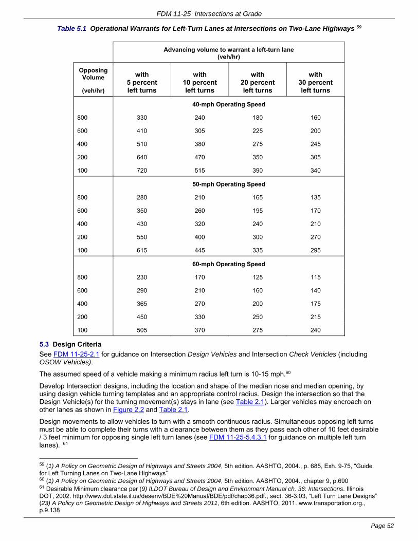
FDM 11-25 Intersections at Grade
Page 52
Table 5.1 Operational Warrants for Left-Turn Lanes at Intersections on Two-Lane Highways 59
Advancing volume to warrant a left-turn lane
(veh/hr)
Opposing Volume
(veh/hr)
with 5 percent left turns
with 10 percent left turns
with 20 percent left turns
with 30 percent left turns
40-mph Operating Speed
800 330 240 180 160
600 410 305 225 200
400 510 380 275 245
200 640 470 350 305
100 720 515 390 340
50-mph Operating Speed
800 280 210 165 135
600 350 260 195 170
400 430 320 240 210
200 550 400 300 270
100 615 445 335 295
60-mph Operating Speed
800 230 170 125 115
600 290 210 160 140
400 365 270 200 175
200 450 330 250 215
100 505 370 275 240
5.3 Design Criteria
See FDM 11-25-2.1 for guidance on Intersection Design Vehicles and Intersection Check Vehicles (including OSOW Vehicles).
The assumed speed of a vehicle making a minimum radius left turn is 10-15 mph.60
Develop Intersection designs, including the location and shape of the median nose and median opening, by using design vehicle turning templates and an appropriate control radius. Design the intersection so that the Design Vehicle(s) for the turning movement(s) stays in lane (see Table 2.1). Larger vehicles may encroach on other lanes as shown in Figure 2.2 and Table 2.1.
Design movements to allow vehicles to turn with a smooth continuous radius. Simultaneous opposing left turns must be able to complete their turns with a clearance between them as they pass each other of 10 feet desirable / 3 feet minimum for opposing single left turn lanes (see FDM 11-25-5.4.3.1 for guidance on multiple left turn lanes). 61
59 (1) A Policy on Geometric Design of Highways and Streets 2004, 5th edition. AASHTO, 2004., p. 685, Exh. 9-75, “Guide for Left Turning Lanes on Two-Lane Highways” 60 (1) A Policy on Geometric Design of Highways and Streets 2004, 5th edition. AASHTO, 2004., chapter 9, p.690 61 Desirable Minimum clearance per (9) ILDOT Bureau of Design and Environment Manual ch. 36: Intersections. Illinois DOT, 2002. http://www.dot.state.il.us/desenv/BDE%20Manual/BDE/pdf/chap36.pdf., sect. 36-3.03, “Left Turn Lane Designs” (23) A Policy on Geometric Design of Highways and Streets 2011, 6th edition. AASHTO, 2011. www.transportation.org., p.9.138

FDM 11-25 Intersections at Grade
Page 53
Restrict on-street parking near the intersection if needed to aid in truck turning movements.
5.3.1 Widths
The width of a left-turn lane is desirably the same as the width of the through lane. Curb adjacent to the left-turn lane is offset to at least the width of the gutter. Provide a turn-lane width of 12 ft on high-speed and transitional rural and suburban arterial highways. Desirably, fully develop the median width upstream from a left-turn lane taper before introducing the taper (i.e., fully shadow the left -turn lane).
Narrower turn lanes are often necessary on urban arterials because of restricted right-of-way and median widths. The minimum and desirable widths for non-slotted left-turn lanes are shown in Table 5.2 below.
The desired minimum separator width at a signalized intersection is 8 feet face to face; the absolute minimum width is 6 feet face to face. This width is required for signal and sign/structure placement, and pedestrian refuge
Table 5.2 Median, Separator, and Turn Lane Widths for non-slotted Left Turn Lanes on Low-Speed Urban Arterials (Minimum Widths)
Highly Developed Area
Outlying Area
Left-turn lane Width (to gutter flange line)
Minimum 10 ft
Desirable 11-12 ft
Separator Width (f/c-f/c )* *
Minimum
The greater of 6 feet
OR
Fixed object width (e.g., sign or signal head) + 2
feet on each side.
The greater of 8 feet
OR
Fixed object width (e.g., sign or signal head) + 2-feet on
each side.
Desirable
10 feet or greater but not less than
Fixed object width (e.g., sign or signal head) + 2 feet on each side.
Total Median Width between opposing traffic lanes where cross traffic storage is NOT required.
Separator width (f/c – f/c*) + gutter width on each side of separator + left-turn lane width.
Total Median Width between opposing traffic lanes where cross traffic storage IS required.
Low Speed Urban Roadways
Desirable: the greater of f/c – f/c* width + gutter width on each side + left-turn lane width, or 30 feet.
Minimum: the greater of f/c – f/c* width + gutter width on each side + left-turn lane width, or 24 feet.
Transitional and High Speed Urban Roadways
the greater of f/c – f/c* width + gutter width on each side + left-turn lane width, or 30 feet.
* f/c-f/c width is the face of curb to face of curb distance between the curb adjacent to the left-turn lane and the curb adjacent to the opposing traffic lane.
See FDM 11-20-1 under “Medians” for further guidance on median widths.
5.3.2 Median End Treatment
A typical intersection does not have a continuous physical edge of traveled way delineating the left-turn path. Instead, the beginning and end of the left-turn path are delineated by:
1. The centerline of an undivided crossroad or the median edge of a divided crossroad, and
2. The curved median end
Under these circumstances, a simple curve for the minimum assumed edge of left turn - known as the control

FDM 11-25 Intersections at Grade
Page 54
radius - is satisfactory. The larger the control radius, the better it will accommodate a given design vehicle, but the resulting layout will have a greater length of median opening and greater paved areas than a minimum radius. These may result in erratic maneuvering by small vehicles, which may interfere with other traffic. On the other hand, a smaller control radius will require wider pavement on the receiving leg to accommodate larger vehicles.
The following control radii can be used for minimum practical design of median ends:
- 40 ft accommodates P vehicles and occasional SU vehicles with some swinging wide;
- 50 ft accommodates SU-30 vehicles and occasional SU-40 and WB-40 vehicles with some swinging wide;
- 60-ft is usually appropriate for right-angle urban intersections (see Attachments 5.1 and 5.2);
- 75 ft accommodates SU-40, WB-40 and and WB-62 vehicles with minor swinging wide at the end of the turn.
- 80 ft is the minimum for rural high-speed 4-lane divided highways (see Attachment 5.4)
- 130 ft accommodates WB-62 vehicles and occasional WB-65 vehicles with minor swinging wide at the end of a turn.62
For a median width of 10 ft or more, the bullet nose is superior to the semicircular end and is the preferred design. A bullet nose is designed to closely fit the path of a turning vehicle and results in less intersection pavement and a shorter median opening than the semicircular shape. The bullet nose is formed by two symmetrical portions of control radius arcs (see R3 - R6 in Attachment 5.1 to 5.3). These arcs need to be large enough to accommodate the turning path of the design vehicle. Assume that the inner wheel of each design vehicle clears the median edge and centerline of the crossroad by 2 ft at the beginning and end of the turn without encroachment on adjacent lanes.
On the OSOW Truck Route (OSOW-TR), use the vehicle inventory of OSOW check vehicles, Attachment 2.1 that may require alternative intersection geometrics See the OSOW maps for routes designated as OSOW-TR available at:
http://dot.wi.gov/osowmaps
Alternative nose configurations may be warranted that allow passage of OSOW vehicles while providing direction to turning vehicles.
Median refuge increases safety for pedestrians and bicyclists crossing a street. A median cut-through is the recommended design for accommodating pedestrians/bicyclists - especially at unsignalized intersection. The face-face median width for pedestrian/bicyclist refuge is desirably 8-feet or greater and minimally 6-feet. See FDM 11-46 for additional guidance on pedestrian accommodations and crossings.
5.3.3 Length
See FDM 11-25-2.3 for guidance on calculating the length of a left turn bay. The length of a median left-turn lane must be adequate for storage or speed change of left-turning vehicles and the entering taper.
Coordinate with the region traffic engineer's staff in determining the required storage length at signalized intersections. Consider using traffic control devices with left-turn indicators when the number of left-turning vehicles exceeds 100 per hour. For additional information, see pp 713-723 of the 2004 GDHS63 and the Highway Capacity Manual.64
Attachment 5.1 and Attachment 5.2 provide guidance on the length and design of turn lanes for urban highways and streets.
Attachment 5.4 illustrates a left-turn lane on a typical rural expressway and includes a table that relates the length of a left-turn lane to the type of rural at-grade intersection into which the traffic is turning.
5.4 Special Designs
5.4.1 Slotted Left-Turn Lanes
A problem with left-turn lanes is the inability of drivers in opposing left-turn bays to see past each other to detect oncoming traffic and pick an adequate gap to complete their maneuver. Although it is desirable to provide a positive offset, as shown in Attachment 5.3 this may not be possible at all locations. Desirably, keep the turning
62 (23) A Policy on Geometric Design of Highways and Streets 2011, 6th edition. AASHTO, 2011. www.transportation.org., section 9.8.2 63 (1) A Policy on Geometric Design of Highways and Streets 2004, 5th edition. AASHTO, 2004. 64 (24) Highway Capacity Manual 2010, 5th edition. Transportation Research Board of the National Academies, 2010.
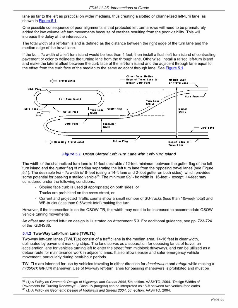
FDM 11-25 Intersections at Grade
Page 55
lane as far to the left as practical on wider medians, thus creating a slotted or channelized left-turn lane, as shown in Figure 5.1.
One possible consequence of poor alignments is that protected left turn arrows will need to be prematurely added for low volume left turn movements because of crashes resulting from the poor visibility. This will increase the delay at the intersection.
The total width of a left-turn island is defined as the distance between the right edge of the turn lane and the median edge of the travel lane.
If the f/c – f/c width of a left-turn island would be less than 4 feet, then install a flush left-turn island of contrasting pavement or color to delineate the turning lane from the through lane. Otherwise, install a raised left-turn island and make the lateral offset between the curb face of the left-turn island and the adjacent through lane equal to the offset from the curb face of the median to the same adjacent through lane. See Figure 5.1.
Figure 5.1 Urban Slotted Left Turn Lane with Left-Turn Island
The width of the channelized turn lane is 14-feet desirable / 12-feet minimum between the gutter flag of the left turn island and the gutter flag of median separating the left turn lane from the opposing travel lanes (see Figure 5.1). The desirable f/c/ - f/c width is18-feet (using a 14-ft lane and 2-foot gutter on both sides), which provides some potential for passing a stalled vehicle65. The minimum f/c/ - f/c width is 16-feet - except, 14-feet may considered under the following conditions:
- Sloping face curb is used (if appropriate) on both sides, or
- Trucks are prohibited on the cross street, or
- Current and projected Traffic counts show a small number of SU-trucks (less than 10/week total) and WB-trucks (less than 0.5/week total) making the turn
However, if the intersection is on the OSOW-TR, this width may need to be increased to accommodate OSOW vehicle turning movements.
An offset and slotted left-turn design is illustrated on Attachment 5.3. For additional guidance, see pp 723-724 of the GDHS66.
5.4.2 Two-Way Left-Turn Lane (TWLTL)
Two-way left-turn lanes (TWLTLs) consist of a traffic lane in the median area, 14-16 feet in clear width, delineated by pavement marking strips. The lane serves as a separation for opposing lanes of travel, an acceleration lane for vehicles turning left to enter the street from midblock driveways, and can be utilized as a detour route for maintenance work in adjacent lanes. It also allows easier and safer emergency vehicle movement, particularly during peak-hour periods.
TWLTLs are intended for use by vehicles traveling in either direction for deceleration and refuge while making a midblock left-turn maneuver. Use of two-way left-turn lanes for passing maneuvers is prohibited and must be
65 (1) A Policy on Geometric Design of Highways and Streets 2004, 5th edition. AASHTO, 2004. “Design Widths of Pavements for Turning Roadways” - Case IIA (tangent) can be interpreted as 18-ft between two vertical-face curbs. 66 (1) A Policy on Geometric Design of Highways and Streets 2004, 5th edition. AASHTO, 2004.
FDM 11-25 Intersections at Grade
Page 56
signed appropriately.
In general, only use TWLTLs in an urban setting where operating speeds are relatively low and where there are no more than two through lanes in each direction. Consider installing a two-way left-turn lane (TWLTL) in existing commercial or residential areas where the existing roadway is undivided (flush median) and where there is a combination of traffic congestion and numerous left-turn maneuvers, coupled with rear-end accidents. Provide median refuge at intersections, particularly unsignalized intersections, for pedestrian crossing. Urban or suburban arterials and collectors are common candidates for a TWLTL. A TWLTL mid-block treatment is less desirable on major arterials and arterials with access management priorities.
Use the following design criteria for TWLTLs67:
- Posted speed: Only use on roads with posted speeds <=45 mph
- TWLTL widths: 14.0-ft Desirable; 12.0-ft Minimum; 16.0-ft Maximum
- Design year AADT:
- 3-Lane TWLTL: between 8,000 and 17,500 vpd
- 5-Lane TWLTL: 24,000 vpd maximum
- 7-Lane TWLTL: NOT ALLOWED
- Length of TWLTL: The length of the TWLTL should have sufficient length to operate properly at the posted speed. Site conditions and the types of intersection treatments will also influence the length of the TWLTL. Use the following guidelines:
- Posted speed of 30 mph or less: 500-feet minimum uninterrupted length
- Posted speed of greater than 30 mph: 1000-feet minimum uninterrupted length
- Railroad Crossings: Do not extend a TWLTL across a highway/railroad grade crossing. Terminate the TWLTL 150 ft to 200 ft in advance of the crossing and provide a raised-curb median adjacent to the railroad. Coordinate with the Region railroad coordinator.
- Intersection Treatment:
- At signalized intersections and at non-signalized intersections/driveways with left-turning turning volumes > 100vph, convert a TWLTL to an exclusive left-turn lane (see FDM 11-25-2.3 for guidance on turn bay length). Use a raised median at intersections and driveways with a high concentration of left turning vehicles and at other locations as needed for pedestrian and bicycle refuge.
- If turning volumes to a non-signalized minor street/driveway are low, it is not necessary to convert the TWLTL to an exclusive left-turn lane. However, pedestrians and bicyclists may still need median refuge.
- Operational/Safety Factors: For traffic to move safely through intersections, drivers need to be able to see stop signs, traffic signals, and oncoming traffic in time to react accordingly. Do not locate a TWLTL where there is substandard stopping sight distance. Provide decision sight distance, where practical, in advance of stop signs, traffic signals, and roundabouts. Appropriate design speed intersection sight distance shall be provided for the drivers of vehicles that are stopped, waiting to cross or enter a through roadway.
- Marking and Signing: Mark and sign TWLTLs in accordance with the Manual on Uniform Traffic Control Devices to identify the lane and regulate its proper use. Additional delineation is possible by either using a different type of pavement material with contrasting color or texture, or a mountable raised median. See MUTCD Figure 3-5 for typical details of marking for two-way left-turn channelization. Two-way left-turn lanes are also discussed in the GDHS68 on pp 474-478
5.4.2.1 Conversion from 4-Lane Undivided to 3-lane TWLTL (“Road Diet”)
Consider converting a four-lane facility to a 3-lane TWLTL - commonly referred to as a “Road Diet” - if the following conditions exist:
- High accident rates involving left turning movements, sideswipes, rear-ends, or crossing traffic
- The need for traffic calming (Lowering the average through traffic speeds and reducing weaving)
- Pedestrian and bicyclist safety issues
- The existing four-lane facility actually operates similar to a 3-lane facility. The inside lanes operate as the left turn lane and the outside lanes operate as the through lane.
67 (25) Two Way Left Turn Lane (TWLTL). Wisconsin DOT, 2007. 68 (1) A Policy on Geometric Design of Highways and Streets 2004, 5th edition. AASHTO, 2004.

FDM 11-25 Intersections at Grade
Page 57
- Projected traffic volumes do not show a drastic increase
Converting a four-lane undivided section to a three-lane cross section may result in less right of way impacts, less environmental impacts and less costs than converting to a wider TWLTL or raised median cross section. The conversion from four to three lanes may also allow the use of wider or designated bike lanes.
Roadways with stop and go traffic such as school buses and delivery trucks or where slow moving heavy vehicles such as long trucks and farm machinery will result in increased through traffic delays. An increased delay for access from side roads may also result with the conversion to three-lanes. A design year ADT of 15,000 - 17,50069 is typically the maximum capacity for a three-lane TWLTL cross section, but check for adequate Level of Service (LOS) (see FDM 11-5-3).
5.4.3 Multiple Left Turn Lanes
Use multiple left-turn lanes at signalized intersections where traffic volumes exceed the capacity of a single left-turn lane. Fully protected signal phasing is required for multiple left turns (refer to TSDM 3-4-1 http://wisconsindot.gov/Pages/doing-bus/local-gov/traffic-ops/manuals-and-standards/tsdm/tsdm.aspx for guidance on left turn phasing). Multiple left turn lanes increase capacity for left turning movements and usually improve overall intersection delay and level of service by allowing a shorter cycle length and reallocation of green time to other movements. However, multiple left turns add to the complexity of the driving task. In addition, because multiple left turns increase exposure for cyclists and pedestrians, adequate clearance times for bicycles and pedestrians is critical.
Multiple left turn lanes are usually NOT appropriate where70.
- A high number of vehicle-pedestrian conflicts may occur.
- Left-turning vehicles do not queue evenly among the left turn lanes because of downstream conditions (e.g., a high potential for downstream weaving may exist).
- Channelization markings within the intersection may become obscured or confusing
- There is insufficient right-of-way to provide adequate turning maneuver space for the design vehicle
5.4.3.1 Design Considerations for Multiple Left Turn lanes
Consider dual left turn lanes at any signalized intersection where left turn demand exceeds 300 vehicles per hour or if the storage length exceeds 300 feet; consider triple left turns where left turn demand exceed 600 vehicles per hour71: Determine the actual need by performing a signalized intersection capacity analysis.
Turn lane widths for multiple turn lanes are 12-ft desirable and 11-ft minimum.
Provide adequate throat width on the intersection leg receiving the multiple left turns to compensate for turning vehicles offtracking and for the relative difficulty of side-by-side left turns. On the other hand, avoid excessive pavement width, because this can mislead drivers. An Intersection where the turning angle is greater than 90-degrees may require a wider throat width than an Intersection where the turning angle is 90-degerees or less72.
Provide a separation between vehicles turning side-by-side of 4-feet desirable / 3-feet minimum (see Figure 5.3). Provide a clearance between simultaneous opposing left- turns as they pass each other of 10 feet desirable / 3-feet minimum. It may be necessary to offset opposing approaches to avoid conflicts in turning paths. If opposing left-turns have inadequate clearance between them then provide separate protective signal phases.
Use lane line extensions to delineate the turning path through an intersection in order to reduce the potential for sideswipe collisions and to increase the efficiency of left-turn operations. This is particularly important where less than desirable clearances are used. Determine lane line (or guideline) and width requirements by plotting
69 (26) Geometric Design of Lanes - Continuous Two-Way Left-Turn Lanes (TWLTLs). In Design Manual ch. 6: Geometric Design Iowa DOT, 2001, sect. 6C-6, pp.1-4. http://www.iowadot.gov/design/dmanual/06c-06.pdf.,(27) Facility Selection / Two - Way Left - Turn Lanes. In MODOT Engineering Policy Guide ch. 200: Geometrics Missouri DOT, 2012, sect. 232.3. http://epg.modot.org/index.php?title=232.3_Two_-_Way_Left_-_Turn_Lanes. 70 (28) Criteria for the Geometric Design of Triple Left-Turn Lanes. ITE Journal, vol. 64, no. 12, 1994, pp.27-33. http://turnlanes.net/files/criteria_for_the_geometric_design_of_triple_left-turn_lanes.pdf.,(29) Individual Movement Treatments / Multiple Left-Turn Lanes. In FHWA-HRT-04-091: Signalized Intersections: Informational Guide Federal Highway Administration Turner-Fairbank Research Center, 2004, ch. 12.1.2, pp.318-319. http://www.tfhrc.gov/safety/pubs/04091/04091.pdf. (30) Triple Left Turn Lanes At Signalized Intersections. BC131 (FINAL). Florida DOT, 2002. http://www.dot.state.fl.us/research-center/Completed_Proj/Summary_TE/FDOT_BC131rpt.pdf. 71 Same references as in previous footnote 72 (31) NYSDOT Highway Design Manual ch. 5: Basic Design. New York State DOT, 2011. https://www.dot.ny.gov/divisions/engineering/design/dqab/hdm/hdm-repository/chapt_5_final.pdf., sec. 5.9.8.2 B, p.5-125

FDM 11-25 Intersections at Grade
Page 58
the swept paths of the selected design vehicles. There should be no conditions that obscure, or result in, confusing pavement markings within the intersection.
Check all turning paths of multiple left turn lanes with truck turning templates allowing 2-ft.between the tire path and edge of each lane.
Provide adequate signing and marking to make the intended operation clear to every road user. Each turn lane should be marked with turn arrows and "ONLY" legends as appropriate.
Provide a raised median island on the receiving leg of the intersection to provide drivers on the inside lane with a visual point of reference to guide the vehicle through the left-turn maneuver.
Because of the added width, signal-timing intervals for bicycle and pedestrian movements require special attention,
5.4.3.1.1 Dual Left Turn Lanes
For details on dual left turn lanes, see Figure 5.4 and Table 5.3.
The receiving roadway needs to carry two through lanes a sufficient distance to allow the effective utilization of both lanes (As a minimum, use the desirable values from the “Tangent Prior to Merge” column in Table A.2.2, from Attachment 2.2).
Assume that the Design Vehicle from Table 2.1 will turn from the outside lane of the dual left turn lanes. Desirably, the inside vehicle should be a SU but, as a minimum, the other vehicle can be a passenger car, 73 if any or all of the following conditions are present:
- Right-of-way is limited
- Trucks are prohibited on cross streets
- Cross street volume is minimal (< 400 ADT) and route is unlikely to be used as a detour route for a nearby higher volume roadway
Table 5.3 shows throat width guidelines for dual lane left turn lanes where the left turning vehicles have a turning angle of 90-degerees or less.
Figure 5.2 Outside and Inside Lanes for Dual Left Turn Lanes
Figure 5.3 Dual Left Turn Lane with Throat Widening on Departure Leg - Design Vehicle & Single Unit 73 ILDOT Bureau of Design and Environment Manual 2002. (9) ILDOT Bureau of Design and Environment Manual ch. 36: Intersections. Illinois DOT, 2002. http://www.dot.state.il.us/desenv/BDE%20Manual/BDE/pdf/chap36.pdf. sect. 36-3.05(b), “Dual Turn Lanes / Design”

FDM 11-25 Intersections at Grade
Page 59
Vehicle Turning Together
Figure 5.4 Dual Left Turn Lanes74
Table 5.3 Expanded Throat Width (W) Guidelines for Dual Left Turn Lanes75
Control Radius (R) (feet)
Expanded Throat Width (W)
(feet)
Intersection Design Vehicle =
‘SU’ truck or Passenger Car
‘WB’ truck
75 33 + gutter width(s) 38 + gutter width(s)
100 31 + gutter width(s) 35 + gutter width(s)
150 30 + gutter width(s) 33 + gutter width(s)
200 30 + gutter width(s) 30 + gutter width(s)
5.4.3.1.2 Triple Left Turn Lanes
Consider triple left turn lanes only if meeting the following conditions76:
- An operational analysis of the intersection shows that a triple left turn lane would correct a situation in which the overall capacity of the intersection is seriously deficient, and that no other geometric or signal modifications would correct the deficiency. Take into account the effects of adjacent intersections, including:
- Traffic backup from a downstream signal on the receiving roadway
- Relative turning movement distribution at a downstream intersection that would compromise the ability of the receiving lanes to store the left turning vehicles
74 Adapted from (9) ILDOT Bureau of Design and Environment Manual ch. 36: Intersections. Illinois DOT, 2002. http://www.dot.state.il.us/desenv/BDE%20Manual/BDE/pdf/chap36.pdf , Figure 36-3U. 75 Adapted from (9) ILDOT Bureau of Design and Environment Manual ch. 36: Intersections. Illinois DOT, 2002. http://www.dot.state.il.us/desenv/BDE%20Manual/BDE/pdf/chap36.pdf, Figure 36-3T,and (32) OHDOT Location Design Manual, Vol.1, Roadway Design ch.400: Intersection Design. Ohio DOT, 2006. http://www.dot.state.oh.us/roadwayengineering/standards/Publications/LDM/2006-07-21/400_jul06.pdf, Figure 401-11E 76 (30) Triple Left Turn Lanes At Signalized Intersections. BC131 (FINAL). Florida DOT, 2002. http://www.dot.state.fl.us/research-center/Completed_Proj/Summary_TE/FDOT_BC131rpt.pdf., p6-7 to 6-9 / 132-134pdf (33) Development of Guidelines for Triple Left and Dual Right-Turn Lanes: Technical Report. FHWA/TX-11/0-6112-1. Texas Transportation Institute, Texas A&M University, 2011. http://tti.tamu.edu/documents/0-6112-1.pdf., pp.6-5 to 6-9 / 121-125pdf

FDM 11-25 Intersections at Grade
Page 60
- The receiving roadway also accommodates heavy volumes from other approaches.
- Upstream features that would make it difficult to distribute approaching left turning vehicles over the three left turn lanes (e.g. a heavy single lane exit ramp from a freeway).
- Triple left turn lanes would not cause a safety problem or aggravate an existing safety problem - including bicycle and pedestrian safety.
- The signal-timing plan must be able to provide adequate pedestrian clearance intervals for all phases.
Typically, design triple left turn lanes using the Design Vehicle from Table 2.1 in both the outside and middle lanes, and an SU vehicle in the inside lane. Desirably, design triple left turn lanes using a WB-65 vehicle (WB-67 if near a freeway) in both the outside and middle lanes, and an SU vehicle in the inside lane. As a minimum, design triple lane turns using an SU vehicle and two P vehicles turning simultaneously with a minimum 4 feet separation between the swept paths of the vehicles. The SU vehicle should be able to turn in all lanes.
Triple left turn configurations featuring three exclusive left turn bays (Type A) are preferable to either two exclusive left turn bays plus an exclusive left turn trap lane (Type B), or two exclusive left turn bays plus an optional through-left lane (Type C)77.
Although three continuous downstream receiving lanes are desirable in order to avoid a lane drop, the receiving roadway needs to carry three through lanes a sufficient distance to allow the effective utilization of those lanes - and at least two continuous downstream lanes exist beyond that point. As a minimum, use the desirable values from the “Tangent Prior to Merge” column in Table A.2.2, from FDM 11-25 Attachment 2.2.
5.4.4 Shared left-turn/thru lanes at Signalized Intersections
Shared left-turn/thru lanes are not desirable at signalized intersections. Only use shared left-turn/thru lanes on minor low-speed streets or on intersection legs where it is physically impossible to provide separate lanes. If used, monitor their crash history, especially along principal roads.
5.5 Tee Intersection Bypass Lane
A Tee intersection bypass lane (also known as a “SHOULDER BYPASS AT THREE-WAY (T) INTERSECTION” and as “LEFT TURN BYPASS LANE”) allows a through vehicle to bypass a left-turning vehicle that is stopped in the traffic lane. See SDD 9A1-a for a detail.
A Tee intersection bypass lane is not as safe as an exclusive left-turn lanes because left turning motorists need to stop or slow down in the thru travel lane. This makes them vulnerable to rear end collisions by inattentive following motorists. However, a Tee intersection bypass lane is preferable to no left-turn treatment at all and can improve the efficiency of traffic operations.
Use a Tee intersection bypass lane at the following locations on non-community bypass 2-lane roads:
- Type A intersections if a left-turn lane is not warranted, or if the construction of a warranted left-turn lane is not technically feasible, leaving no left-turn treatment as the only other alternative,
- Non-Type A intersections if the construction of a warranted left-turn lane is not technically feasible, leaving no left-turn treatment as the only other alternative,
- Consider at non-Type A intersections where a left-turn lane is not warranted.
Do not use a Tee intersection bypass lane at a four-legged intersection.
Use exclusive left turn lanes with positive offsets at all intersections on a 2-lane community bypass. Do not use Tee intersection bypass lanes.78
5.6 References
1. A Policy on Geometric Design of Highways and Streets 2004, 5th edition. AASHTO, Washington, DC, 2004.
9. ILDOT Bureau of Design and Environment Manual ch. 36: Intersections. Illinois DOT, 2002. http://www.dot.state.il.us/desenv/BDE%20Manual/BDE/pdf/chap36.pdf. Accessed 1-8-2010.
12. Stover, V. G. and F. J. Koepke. Transportation and Land Development, 2nd edition. Institute of Transportation Engineers, Washington, DC, 2006.
13. Bonneson, J. A. and M. D. Fontaine. NCHRP Report 457: Engineering Study Guide for Evaluating
77 (28) Criteria for the Geometric Design of Triple Left-Turn Lanes ITE Journal, vol. 64, no. 12, 1994, pp.27-33. http://turnlanes.net/files/criteria_for_the_geometric_design_of_triple_left-turn_lanes.pdf. 78 (21) Review of Wisconsin Bypass Road Design Practices February 13-14, 2006. (Final). Federal Highway Administration Resource Center, 2006. http://www.dot.wisconsin.gov/library/publications/docs/wis-bypass-report.pdf.

FDM 11-25 Intersections at Grade
Page 61
Intersection Improvements. TRB, National Research Council, Washington, DC, 2001. http://onlinepubs.trb.org/onlinepubs/nchrp/esg/esg.pdf.
14. Manual on Uniform Traffic Control Devices. Federal Highway Administration, Washington, DC, 2009.
15. Gattis, J. L. and S. T. Low. Intersection Angle Geometry and the Driver's Field of View. In Transportation Research Record 1612: Highway Geometric Design Issues. TRB, National Research Council, Washington, DC, 1998, pp. 10-16.
16. Staplin, L. K., K. Lococo, S. R. Byington, and Scientex Corporation. Highway Design Handbook for Older Drivers and Pedestrians. FHWA-RD-01-103. Federal Highway Administration Turner-Fairbank Highway Research Center, McClean, VA, May, 2001. http://www.tfhrc.gov/humanfac/01103/coverfront.htm. Accessed 4-2-2009.
17. Staplin, L., K. Lococo, S. Byington, D. Harkey, and FHWA. Guidelines and Recommendations to Accommodate Older Drivers and Pedestrians. FHWA-RD-01-051. Federal Highway Administration, McLean, VA, May, 2001. http://www.tfhrc.gov/humanfac/01105/cover.htm. Accessed 3-16-2006.
18. Staplin, L., K. Lococo, and S. Byington. Older Driver Highway Design Handbook [ch.1 - Intersections (At-Grade)]. FHWA-RD-97-135. Federal Highway Administration, Washington, DC, Jan., 1998. http://www.tfhrc.gov/safety/pubs/97135/index.htm#intro. Accessed 2-3-2009.
19. Rural Intersections - Turn lanes - Left-Turn Bypass Lanes. In MNDOT Road Design Manual ch. 5: At-Grade Intersections. Minnesota DOT, 2000, sect. 5-4.01.04, pp. 5-4(2). http://www.dot.state.mn.us/design/rdm/english/5e.pdf. Accessed 2-3-2009.
20. Baumann, A. J. Minimum Required Turn Lane Storage Lengths & Tapers For Left & Right Turn Lanes At Signalized & Non-signalized Intersections. (DRAFT). Wisconsin DOT, Feb. 25, 2010 current revision (created Dec 2, 2008; previously revised: Nov 4, 2009).
21. FHWA Resource Center Safety and Design Team. Review of Wisconsin Bypass Road Design Practices February 13-14, 2006. (Final). Federal Highway Administration Resource Center, Olympia Fields, IL, 2006. http://www.dot.wisconsin.gov/library/publications/docs/wis-bypass-report.pdf. Accessed 4-2-2009.
22. Rationale for Median Type Recommendations. Kentucky Transportation Cabinet, 2008. http://www.planning.kytc.ky.gov/congestion/medians/Median%20Type%20Guidelines.pdf. Accessed 5-3-2012.
23. A Policy on Geometric Design of Highways and Streets 2011, 6th edition. AASHTO, Washington, DC, 2011. www.transportation.org.
24. Highway Capacity Manual 2010, 5th edition. Transportation Research Board of the National Academies, Washington, DC, 2010.
25. Revello, B. Two Way Left Turn Lane (TWLTL). Wisconsin DOT, Nov. 26, 2007.
26. Geometric Design of Lanes - Continuous Two-Way Left-Turn Lanes (TWLTLs). In IADOT Design Manual ch. 6: Geometric Design. Iowa DOT, 2001, sect. 6C-6, pp. 1-4. http://www.iowadot.gov/design/dmanual/06c-06.pdf. Accessed 5-3-2012.
27. Facility Selection / Two - Way Left - Turn Lanes. In MODOT Engineering Policy Guide ch. 200: Geometrics. Missouri DOT, 2012, sect. 232.3. http://epg.modot.org/index.php?title=232.3_Two_-_Way_Left_-_Turn_Lanes. Accessed 5-3-2012.
28. Ackeret, K. W. Criteria for the Geometric Design of Triple Left-Turn Lanes. ITE Journal, vol. 64, no. 12, 1994 December, pp. 27-33. http://turnlanes.net/files/criteria_for_the_geometric_design_of_triple_left-turn_lanes.pdf. Accessed 7-24-2012.
29. Rodegerdts, L. A., B. Nevers, B. Robinson, J. Ringert, P. Koonce, J. Bansen, T. Nguyen, J. McGill, D. Stewart, J. Suggett, T. Neuman, N. Antonucci, K. Hardy, and K. Courage. Individual Movement Treatments / Multiple Left-Turn Lanes. In FHWA-HRT-04-091: Signalized Intersections: Informational Guide. Federal Highway Administration Turner-Fairbank Research Center, McLean, VA, 2004, ch. 12.1.2, pp. 318-319. http://www.tfhrc.gov/safety/pubs/04091/04091.pdf. Accessed 8-6-2007.
30. Courage, K., A. Gan, B. Stephens, M. Willis, and University of Florida Transportation Research Center. Triple Left Turn Lanes At Signalized Intersections. BC131 (FINAL). Florida DOT, Tallahassee, FL, Dec., 2002. http://www.dot.state.fl.us/research-center/Completed_Proj/Summary_TE/FDOT_BC131rpt.pdf. Accessed 7-30-2012.
31. NYSDOT Highway Design Manual ch. 5: Basic Design. New York State DOT, Albany, NY, 2011. https://www.dot.ny.gov/divisions/engineering/design/dqab/hdm/hdm-repository/chapt_5_final.pdf. Accessed 7-

FDM 11-25 Intersections at Grade
Page 62
30-2012.
32. OHDOT Location & Design Manual, Vol.1, Roadway Design ch.400: Intersection Design. Ohio DOT, 2006. http://www.dot.state.oh.us/roadwayengineering/standards/Publications/LDM/2006-07-21/400_jul06.pdf.
33. Cooner, S. A., S. E. Ranft, Y. K. Rathod, Y. Qi, L. Yu, Y. Wang, and S. Chen. Development of Guidelines for Triple Left and Dual Right-Turn Lanes: Technical Report. FHWA/TX-11/0-6112-1. Texas Transportation Institute, Texas A&M University, College Station, TX, Jan., 2011 Published July 2011. http://tti.tamu.edu/documents/0-6112-1.pdf. Accessed 7-24-2012.
LIST OF ATTACHMENTS
Attachment 5.1 Urban Median Opening and Intersection Guidelines
Attachment 5.2 Median Openings and Left Turn Lanes in Urban Roadways
Attachment 5.3 Details for Slotted Left Turn Lanes and Median Opening Openings at Urban Intersections
Attachment 5.4 Median Opening with Left Turn Lane on Rural High-Speed 4-Lane Divided Highway
FDM 11-25-10 Right-Turn Lanes June 24, 2016
10.1 Introduction
These guidelines apply to right-turn lanes at intersections without channelizing islands. See FDM 11-25-15 for guidance about channelized right-turn lanes.
A right-turn bay can significantly improve operations and safety at the intersection because it effectively separates those vehicles that are slowing or stopping to turn from those vehicles in the through traffic lanes. This separation minimizes turn-related collisions (e.g., angle, rear-end, and same-direction-sideswipe) and unnecessary delay to through vehicles.79
The selection of a right turn radius requires consideration of design speed, types of turning vehicles, type of intersection by location (rural, urban or suburban), pedestrian needs and whether the through highway is divided or undivided.
The assumed speed of a vehicle making a right turn at an intersection designed for minimum-radius turns is less than 10 mph.80
When providing a designated right turn lane, continue the bicycle accommodation adjacent to the turn lane and thru the intersection (as shown in SDD 15C29). This is particularly important at signalized intersection and intersections with pork chop islands. See FDM 11-46-15 for additional guidance. The Intersection Design Vehicle (see FDM 11-25-2.1 and Table 2.1) does not encroach into a contiguous bike lane between a right-turn lane and a travel lane. Check the swept path of the Intersection Check Vehicle(s) (e.g., a WB-65) to see if it is possible to avoid encroaching into the bike lane without significantly disrupting traffic or going outside of the roadway. Otherwise, consider:
- accepting infrequent bike lane encroachments but consider a warning sign that right turning large trucks pull left before turning.
- If bike lane encroachment is frequent enough to be potentially dangerous, consider:
- parking restrictions and/or a larger curb radius
- mark as a shared bike/right-turn lane instead of a separate bike lane and right-turn lane
- re-design to reduce or eliminate the conflict
10.2 Intersections in Rural and Developing Areas
Refer to Attachment 1.1 for guidance about right turn lanes on rural high-speed highways.
10.2.1 Storage Length
The right-turn lane lengths in the standard rural intersection designs (discussed in Attachment 1.1) are for deceleration of turning vehicles. Where cross road traffic volumes are high, additional length may be needed to 79 See Bonneson & Fontaine in NCHRP Report 457 (13) NCHRP Report 457: Engineering Study Guide for Evaluating Intersection Improvements. TRB, National Research Council, 2001. http://onlinepubs.trb.org/onlinepubs/nchrp/esg/esg.pdf., pp. 22-23) 80 (1) A Policy on Geometric Design of Highways and Streets 2004, 5th edition. AASHTO, 2004., p.583, “Minimum edge of Traveled Way Designs”

FDM 11-25 Intersections at Grade
Page 63
accommodate vehicle storage. Storage requirements should also be evaluated where signals are added to the intersection. See FDM 11-25-2.2 for guidance on queue storage requirements.
The length of turn lane required for vehicle storage should be determined in cooperation with the region traffic engineer's staff based on a length of 25 feet per vehicle stored. If the intersection is on the OSOW Truck Route (OSOW-TR), depending on frequency of load, it may be appropriate to consider additional length for OSOW vehicles.
10.3 Two-Way Stop-Controlled Intersections on Urban Low Speed and Transitional Roads
Check with traffic operations on the need for right turn lanes. Accommodate transit, pedestrian and bicyclists roadway users.
Use the charts in Figure 10.1 as an aid in determining whether to add a right-turn bay on the major road at a two-way stop-controlled intersection.
See FDM 11-25-10.4 below for guidance on signalized intersections.
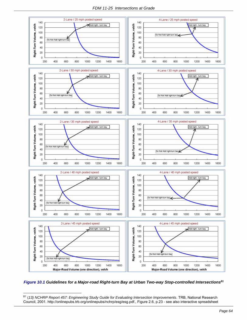
FDM 11-25 Intersections at Grade
Page 64
Figure 10.1 Guidelines for a Major-road Right-turn Bay at Urban Two-way Stop-controlled Intersections81
81 (13) NCHRP Report 457: Engineering Study Guide for Evaluating Intersection Improvements. TRB, National Research Council, 2001. http://onlinepubs.trb.org/onlinepubs/nchrp/esg/esg.pdf., Figure 2.6, p.23 - see also interactive spreadsheet
FDM 11-25 Intersections at Grade
Page 65
10.3.1 Corner Curb Radius
Central Business District (CBD) streets are typically undivided and often operate as one-way roadways. A minimum corner radius of 10 feet may be adequate for these streets especially where there is pedestrian activity and little truck traffic. Progressively larger corner radii are required depending on the functional classification of the intersecting street; at least 15 feet for locals, 20 feet for collectors and 25 feet for arterials. Large trucks can be accommodated with these radii if encroachment into the opposing traffic lane can be allowed and parking can be held back from the corner by at least two spaces. See Chapter 9 of 2004 AASHTO GDHS sections, “Effect of Curb Radii on Pedestrians” and “Corner Radii into Local Urban Streets”.82
Where there are a significant number of trucks turning and encroachment into the opposing lanes cannot be allowed, the corner should be designed using an appropriate turning template or three centered compound curves. See 2004 AASHTO GDHS Exhibit 9-42, "Typical Designs for Turning Roadways". Pedestrian, bicycle and transit accommodations and signal locations need to be included in the design accordingly .
Where truck volumes are not significant, the right turn radius can be as small as 10 feet in downtown streets and 25 feet at intersections with arterial streets. Intersections that handle large numbers of turning trucks require a minimum corner radius of 30 feet to turn onto a four lane divided highway where the semitrailer can encroach into the median lane. Truck drivers will use the median lane when necessary which is allowed under state law for large trucks. A larger radius should be provided where possible. However, a radius greater than 45 feet should not be used because it can cause substantial problems with the location of stop signs, traffic signals, pedestrian push buttons, and crosswalk locations. A large radius also causes crosswalks to be extra long which results in more pedestrian exposure and visibility problems.
The corner radius can be shorter where the intersection is on a street where parking is permitted. However, future growth in traffic volumes may demand that the parking lane be converted to a traffic lane. If this is foreseeable, a large radius should be provided.
For additional guidance, see 2004 AASHTO GDHS sections, ”Minimum Edge of Traveled Way Design” and “Design For Specific Conditions (Right Angle Turns”83.
10.3.2 Lane Width
The width of a non-channelized right turn lane should generally be the same as the width of the through lane. For guidance on the use of narrower lanes, see Table 5.2. The desirable width for channelized right turn lanes is discussed in FDM 11-25-15.
10.3.3 Lane Length
See FDM 11-25-2.3.
10.4 Signalized Intersection Considerations
Consider providing exclusive right turn lanes for all approaches at a signalized intersection. A right turn lane provides refuge for safe deceleration outside a high speed through lane and provides storage for right-turning vehicles to assist in optimizing traffic signal phasing.
Improperly designed right turn radii most likely will result in traffic signal knockdowns. A flat corner curb radius (i.e.,>70 feet) creates a traffic signal design problem when locating the near right traffic signal. The preferred solution is to design a small pork chop island (minimum of 150 square feet) to place the traffic signal and lighting bases, pull boxes, pedestrian pushbuttons, and pedestrian walkways. The island also facilitates channelization of the right turn movement (see FDM 11-25-15 for guidance on channelized right turns).
10.4.1 Dual Right Turn Lanes
Dual right-turn lanes have typically been installed at signalized intersections and at roundabout right-turn bypass lanes on urban arterial roadways and interchange ramps. Determine the actual need by performing a signalized intersection capacity analysis. Use dual right-turn lanes only if necessary because they are particularly difficult for bicyclists and pedestrians84. Dual right-turn lanes at signalized intersections are required to be signal-controlled. See FDM 11-26 for guidance on dual right-turn lanes at roundabout right-turn bypasses.
included in on-line version, “http://onlinepubs.trb.org/onlinepubs/nchrp/esg/figure 2-6.xls” (NCHRP references from “NCHRP Report 457” are reproduced with permission of the TRB through the National Academy of Sciences (NAS)) 82 (1) A Policy on Geometric Design of Highways and Streets 2004, 5th edition. AASHTO, 2004., pp.614-621 83 (1) A Policy on Geometric Design of Highways and Streets 2004, 5th edition. AASHTO, 2004., pp.634-639 84 (33) Development of Guidelines for Triple Left and Dual Right-Turn Lanes: Technical Report. FHWA/TX-11/0-6112-1. Texas Transportation Institute, Texas A&M University, 2011. http://tti.tamu.edu/documents/0-6112-1.pdf., p.6-2

FDM 11-25 Intersections at Grade
Page 66
There are generally two reasons for using dual right-turn lanes85:
1. To accommodate high right turn volumes and provide enhanced capacity at intersections where a single right-turn lane is not adequate and a free-flow right turn lane is not advisable
2. To mitigate weaving traffic conflicts, e.g. drivers who are making a left-turn at the next downstream intersection would make their turn from the left-hand lane of the dual right-turn lanes
Research has shown that a well-designed dual right-turn lane does not cause significantly higher crash frequency or severity compared to a single right-turn lane86 and will usually improve the operations of intersections. The additional deceleration and storage space helps prevent spillover into adjacent through lanes. Right-turning traffic requires less green time, and this time thus can be allocated to other movements. However, because of the added width, signal-timing intervals for bicycle and pedestrian movements require special attention,
Consider using dual right-turn lanes at an intersection with a single right-turn lane - and where the receiving leg has at least two lanes - if one of the following conditions exists87:
- The right-turn volume is greater than 500 vph;
- There is not sufficient space to provide the necessary length of a single turn lane because of restrictive site conditions (e.g., closely spaced intersections),
- The required length of a single turn lane becomes excessive (usually about 300-ft or greater)
- The volume to capacity ratio for a single right-turn lane is greater than or equal to 0.90, or LOS is worse than D
- Right-turn green time and green time from an overlap are not sufficient to handle the right-turn volume
There are two (2) types of dual right-turn lane configurations:
1. Shared dual right-turn lanes: the right hand lane (i.e., the curb lane) is an exclusive right-turn lane and the left-hand lane is a shared right-turn/thru lane
2. Exclusive dual right-turn lanes: both the right-hand lane and the left-hand lane are exclusive right-turn lanes
Exclusive dual right-turn lanes are generally preferable because they provide more capacity enhancement. Exclusive dual right-turn lanes also allow for placement of a bicycle lane between the through lane and the right-turn lanes.88
The shared right-turn/thru lane has lower lane utilization than an exclusive right-turn lane because thru vehicles block right-turning vehicles during protected right-turn phases; the lower lane utilization may result in the need for longer storage in the curb right-turn lane. In addition, shared dual right-turn lanes, do not allow for placement of a bicycle lane between the shared right-turn/thru lane and the exclusive right-turn lane (or between the exclusive thru lane and the shared right-turn/thru lane). However, shared dual right-turn lanes are preferred where:
- More flexibility is needed to use an optional lane
- Less impacts on the adjacent through movement is desired
- Right-of-way for providing an additional turn lane is restricted
By statute89, Right turns on red (RTOR), when permitted, are allowed from the right-hand (i.e., curb) lane and the leftmost right-turn lane of a roadway that provides two right-turn lanes provided that it is into a lawfully available lane that is second to the rightmost lane for traffic moving to the right. Except for a vehicle turning right from the leftmost right-turn lane of a roadway that provides two right-turn lanes, no turn may be made on a red signal if lanes of moving traffic are crossed.
Pull the curb lane out beyond the left-hand turn lane so drivers in the curb lane have a clear unobstructed view of approaching traffic. Consider prohibiting right-turn-on-red (RTOR) from a dual right-turn lane if one or more of following conditions exist:90
85 (34) Development of Warrants for Installation of Dual Right-Turn Lanes at Signalized Intersections. SWUTC/12/161141-1. Texas Transportation Institute, Texas A&M University, 2012. http://d2dtl5nnlpfr0r.cloudfront.net/swutc.tamu.edu/publications/technicalreports/161141-1.pdf., p.91-95 / 107-111pdf 86 Reference (34), p.18 / 34pdf 87 Reference (34), p.91 / 107pdf 88 Reference (34), pp34-35, 94 / 50-51, 110pdf 89 Section 346.37(1)(c)3, Wis. Stats 90 Reference (34), p.95 / 111pdf

FDM 11-25 Intersections at Grade
Page 67
- Insufficient sight distance
- Frequent presence of pedestrians
- Use of split phase
- Significant U-turns from right-hand cross-street
- High crash history
- High-speed road, onto which subject RTOR vehicles turns
- Inadequate capacity of receiving lanes
There are some potential issues with dual right-turn lanes, including91:
- Sideswipes between turning vehicles are a possibility at double turn lanes. This is especially an issue if the turn radius is tight and large vehicles are likely to be using the turn lanes. Delineation of turn paths should help address this issue.
- Impaired intersection sight distance (ISD) for drivers in the right-hand turn lane due to vehicles in the left-hand lane obstructing their view of on-coming traffic
- Right-of-way acquisition may be expensive.
- Possible access restrictions to adjacent properties
- Dual right-turn lanes make crosswalks longer, which can affect minimum cycle time, increase pedestrian exposure, and precipitate long pedestrian clearance intervals that may or may not work with coordination timing plans.
- Pedestrian movement may also be less safe because a vehicle in the curb lane whose driver is yielding to a pedestrian can block sight lines for drivers in the left-hand turn lane
Design considerations for dual right-turn lanes include92:
- Check all turning paths of dual right-turn lanes with truck turning templates allowing 2-ft.between the tire path and edge of each lane.
- Provide a separation between vehicles turning side-by-side of 4-feet desirable / 3-feet minimum.
- Turn lane widths for dual right-turn lanes are 12-ft desirable and 11-ft minimum.
- The minimum width of channelized roadway for dual right-turn lanes is 30-feet, not including gutters.
- Determine the length of dual right-turn lanes as discussed in FDM 11-25-2.
- WisDOT’s practice93 is to assume that the Intersection Design Vehicle (see FDM 11-25 Table 2.1) turns from the left-hand lane of the dual right turn lanes (see Figure 10.2). However, there may be locations where it is appropriate to assume that the Intersection Design Vehicle turns from the right-hand lane (for example, a significant number of the vehicles are making a right turn at a close by downstream intersection or driveway). Desirably, the vehicle in the other lane (typically, the right-hand lane) should be a SU truck but, as a minimum, can be a passenger car94, if any or all of the following conditions are present:
- Right-of-way is limited
- Trucks are prohibited on cross streets
- Cross street volume is minimal (< 400 ADT) and route is unlikely to be used as a detour route for a nearby higher volume roadway
91 Reference (34), pp5, 41-42 / 21, 57-58pdf 92 Reference (34), pp5-14 / 21-30pdf 93 per interim TSDM 3-3-4, July 2009 94 ILDOT Bureau of Design and Environment Manual 2002 (9) ILDOT Bureau of Design and Environment Manual ch. 36: Intersections. Illinois DOT, 2002. http://www.dot.state.il.us/desenv/BDE%20Manual/BDE/pdf/chap36.pdf. sect. 36-3.05(b), “Dual Turn Lanes / Design”

FDM 11-25 Intersections at Grade
Page 68
Figure 10.2 Dual Right-Turn Lanes
- Dual right-turn lanes require sufficient turn radii to allow a smooth turn from both turn lanes, but not so large as to encourage excess speed.
- Provide adequate throat width on the intersection leg receiving the dual right turns to compensate for turning vehicles offtracking and for the relative difficulty of side-by-side right turns. Provide throat widening comparable to that used for dual left-turn lanes (see FDM 11-25-5.4.3.1.1, including Table 5.3 and Figure 5.4). Consider how throat widening will affect the traffic approaching from the other side. Make sure that the through lanes line up relatively well to ensure a smooth flow of traffic through the intersection.
- The receiving roadway needs to carry two through lanes a sufficient distance to allow the effective utilization of both lanes (As a minimum, use the desirable values from the “Tangent Prior to Merge” column in Table A.2.2, from FDM 11-25 Attachment 2.2) - but not less than 150-ft.
- Truck traffic utilization is an issue when designing dual right-turn lanes. Similar to a roundabout, if designed too wide to accommodate truck traffic, then traffic may create a "third turn lane", especially during snowy conditions.
- Avoid installing dual right-turn lanes near access points (e.g., from gas stations, parking lots, or other traffic generators).
- For closely spaced intersections, if a downstream intersection uses dual right-turn lanes, do not align the curb right-turn lane with any through lane at the upstream intersection.
- Provide adequate signing and marking to make the intended operation clear to every road user. Each turn lane should be marked with turn arrows and "ONLY" legends as appropriate. Use lane line extensions to delineate the turning path through an intersection in order to reduce the potential for sideswipe collisions and to increase the efficiency of right-turn operations. Determine lane line (or guideline) and width requirements by plotting the swept paths of the selected design vehicles. There should be no conditions that obscure, or result in, confusing pavement markings within the intersection.
10.5 References
1. A Policy on Geometric Design of Highways and Streets 2004, 5th edition. AASHTO, Washington, DC, 2004.
13. Bonneson, J. A. and M. D. Fontaine. NCHRP Report 457: Engineering Study Guide for Evaluating Intersection Improvements. TRB, National Research Council, Washington, DC, 2001. http://onlinepubs.trb.org/onlinepubs/nchrp/esg/esg.pdf. 95
95 [Dec 3, 2012 email from Ellen Chafee, Editor, CRP-TRB] The TRB through the National Academy of Sciences (NAS) grants permission to use the material listed below from Maze et al. (2010) NCHRP Report 650:Median Intersection Design for Rural High-Speed Divided Highways and J. A. Bonneson and M. D. Fontaine (2001) NCHRP Report 457: Engineering Study Guide for Evaluating Intersection Improvements in a proposed revision to Chapter 11, Section 25 of Wisconsin DOT’s Facilities Development Manual (FDM 11-25). NCHRP Report 650 Table 19 p. 47 NCHRP Report 650 Figure 117 p. 148 NCHRP Report 650 Figure 31 p. 49 NCHRP Report 650 Figure 65 p. 86 NCHRP Report 650 Figure 48 p. 65 NCHRP Report 457 Figure 2.6 p. 23 NCHRP Report 457 Figure 2-6.xls Interactive spreadsheet in online version Permission is also granted for any subsequent versions of the Work, including versions made for use with blind or physically handicapped persons, and all foreign-language translations of the Work prepared for distribution throughout the world. Permission is given with the understanding that inclusion of the material will not be used to imply Transportation Research Board, AASHTO, Federal Highway Administration, Transit Development Corporation, Federal Transit Administration, Federal

FDM 11-25 Intersections at Grade
Page 69
33. Cooner, S. A., S. E. Ranft, Y. K. Rathod, Y. Qi, L. Yu, Y. Wang, and S. Chen. Development of Guidelines for Triple Left and Dual Right-Turn Lanes: Technical Report. FHWA/TX-11/0-6112-1. Texas Transportation Institute, Texas A&M University, College Station, TX, Jan., 2011 Published July 2011. http://tti.tamu.edu/documents/0-6112-1.pdf. Accessed 7-24-2012.
34. Yi, Q., C. Xiaoming, D. Li, and Center for Transportation Training and Research - Texas Southern University. Development of Warrants for Installation of Dual Right-Turn Lanes at Signalized Intersections. SWUTC/12/161141-1. Texas Transportation Institute, Texas A&M University, College Station, TX, Apr., 2012. http://d2dtl5nnlpfr0r.cloudfront.net/swutc.tamu.edu/publications/technicalreports/161141-1.pdf. Accessed 1-9-2013.
FDM 11-25-15 Turning Roadways (Channelized Right) March 4, 2013
15.1 Criteria
At intersections with a considerable number of turning movements, especially by trucks, and where it is desirable to maintain a turning speed for passenger vehicles of roughly 15 mph (25 km/h) or greater, a separate turning roadway or channelized right-turning lane should be provided between intersection legs. Check the turning movements of OSOW vehicles if needed (see FDM 11-25 Table 2.2). Verify that OSOW vehicles are not prohibited from turning at the intersection where needed.
The term "turning roadways" also applies to ramps and ramp terminals, particularly at the crossroad. Refer to FDM 11-30 Attachment 1.3, 1.4, 1.5, and 1.6 for geometrics at ramp terminals.
15.2 Speed And Curvature
The speed maintained on the free flow segment of turning roadways is governed by the radius of curve and superelevation (see FDM 11-10-5 for superelevation guidance). "Free-Flow Turning Roadways at Intersections" are discussed on pages 639-649, GDHS.
Compound curves should be used at the downstream connection with the departure leg of the intersection to avoid vehicle encroachment onto the curb or shoulders. Three-centered compound curves for vehicles of different design classification are shown in Exhibit 9-20, pages 584-591, GDHS96. It is desirable that the right turn radius be kept as small as possible to avoid excess speed, while still accommodating the Intersection Design Vehicle.
15.3 Design Guides
The width of turning roadways should accommodate the design class of vehicle that is anticipated. For turning lanes that are longer than 50 feet, provisions should be made to pass a stalled vehicle in the turning lane. The design width of pavement for turning roadways is shown in Exhibit 3-51, page 220, GDHS97 with 15 feet as a minimum plus the gutter width. "Turning Roadways with Corner Islands" are discussed on pages 634-639 GDHS.
Channelized right turns should be brought in as close to perpendicular as possible for vision to the left. Right turn lanes separated by islands having intersecting angles less than 60 degrees with the cross street require the driver to look back over their left shoulder to view oncoming traffic, which is particularly difficult for older drivers. Design right turn islands in urban/suburban areas with the right-turn lane at an angle as close to 90-degrees as possible, based on the guidance in FDM 11-25-2.7, “Angle of Intersection”, and as shown in Figure 15.1.
Aviation Administration, or Federal Motor Carriers Safety Administration endorsement of a particular product, method, or practice. Permission is also provided on condition that appropriate acknowledgment will be given as to the source material. 96 (1) A Policy on Geometric Design of Highways and Streets 2004, 5th edition. AASHTO, 2004. 97 (1) A Policy on Geometric Design of Highways and Streets 2004, 5th edition. AASHTO, 2004.
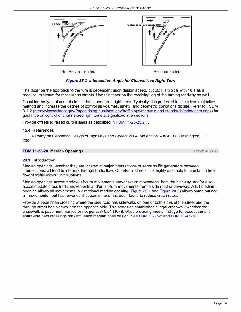
FDM 11-25 Intersections at Grade
Page 70
Figure 15.1 Intersection Angle for Channelized Right Turn
The taper on the approach to the turn is dependent upon design speed, but 20:1 is typical with 10:1 as a practical minimum for most urban streets. Use this taper on the receiving leg of the turning roadway as well.
Consider the type of controls to use for channelized right turns. Typically, it is preferred to use a less restrictive method and increase the degree of control as volumes, safety, and geometric conditions dictate. Refer to TSDM 3-4-2 (http://wisconsindot.gov/Pages/doing-bus/local-gov/traffic-ops/manuals-and-standards/tsdm/tsdm.aspx) for guidance on control of channelized right turns at signalized intersections.
Provide offsets to raised curb islands as described in FDM 11-25-25.2.1.
15.4 References
1. A Policy on Geometric Design of Highways and Streets 2004, 5th edition. AASHTO, Washington, DC, 2004.
FDM 11-25-20 Median Openings March 4, 2013
20.1 Introduction
Median openings, whether they are located at major intersections or serve traffic generators between intersections, all tend to interrupt through traffic flow. On arterial streets, it is highly desirable to maintain a free flow of traffic without interruptions.
Median openings accommodate left-turn movements and/or u-turn movements from the highway; and/or also accommodate cross traffic movements and/or left-turn movements from a side road or driveway. A full median opening allows all movements. A directional median opening (Figure 20.1 and Figure 20.2) allows some but not all movements - but has fewer conflict points - and has been found to reduce crash rates.
Provide a pedestrian crossing where the side road has sidewalks on one or both sides of the street and the through street has sidewalk on the opposite side. This condition establishes a legal crosswalk whether the crosswalk is pavement marked or not per ss340.01 (10) (b).Also providing median refuge for pedestrian and share-use path crossings may influence median nose design. See FDM 11-25-5 and FDM 11-46-10.

FDM 11-25 Intersections at Grade
Page 71
Figure 20.1 Directional Median Opening98
Figure 20.2 Separator Overlap for Directional Median Opening99
If there is sufficient space, providing unsignalized directional openings between signalized intersections facilitates access to abutting properties and reduces U-turns / left turns at the signalized intersections. The operations of the adjacent signalized intersections are of greater importance than the midblock opening(s). The midblock opening(s) must not compromise the design or operations of the signalized intersections.
98 Adapted from (11)Access Management Manual. Transportation Research Board, 2003., Figure 11-4 on p.207. Copyright, National Academy of Sciences, Washington, D.C., 2003. Reproduced with permission of the Transportation Research Board. 99 Adapted from (11)Access Management Manual. Transportation Research Board, 2003., Figure 11-7, p. 209. Copyright, National Academy of Sciences, Washington, D.C., 2003. Reproduced with permission of the Transportation Research Board.
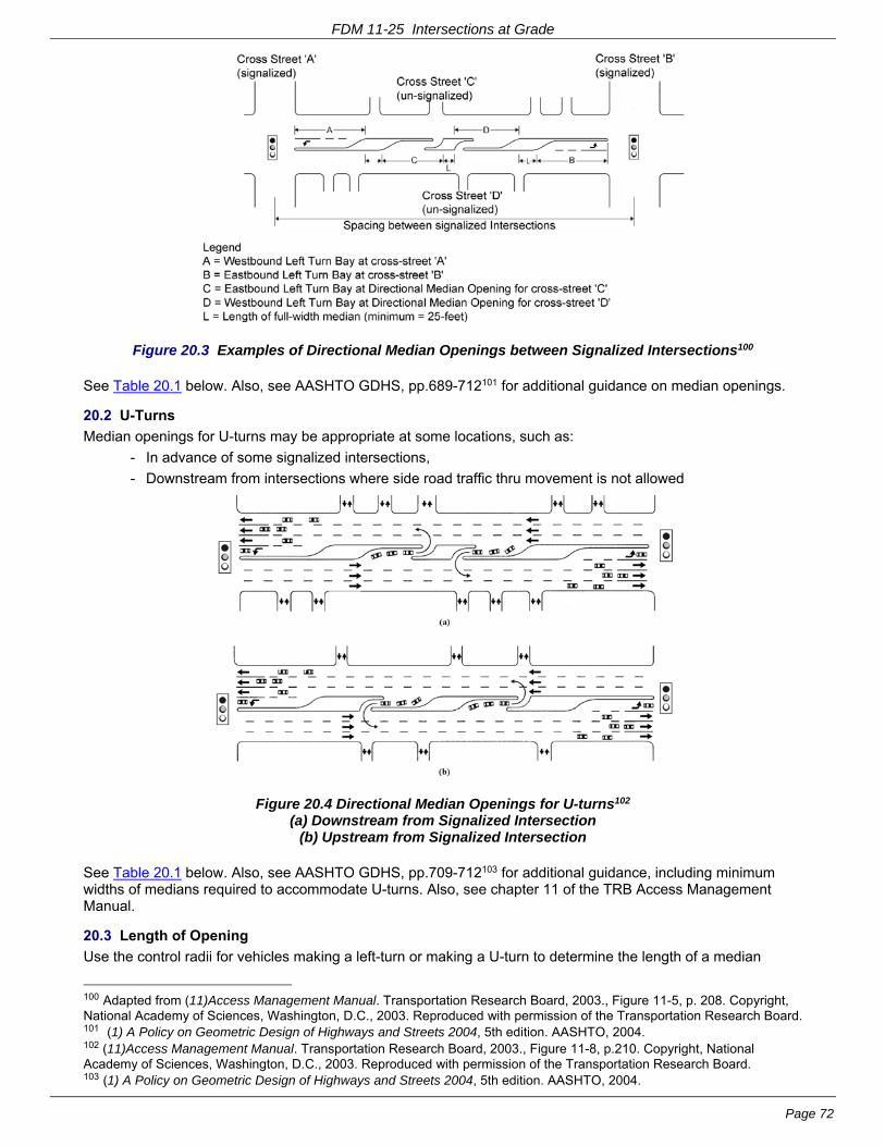
FDM 11-25 Intersections at Grade
Page 72
Figure 20.3 Examples of Directional Median Openings between Signalized Intersections100
See Table 20.1 below. Also, see AASHTO GDHS, pp.689-712101 for additional guidance on median openings.
20.2 U-Turns
Median openings for U-turns may be appropriate at some locations, such as:
- In advance of some signalized intersections,
- Downstream from intersections where side road traffic thru movement is not allowed
Figure 20.4 Directional Median Openings for U-turns102 (a) Downstream from Signalized Intersection
(b) Upstream from Signalized Intersection
See Table 20.1 below. Also, see AASHTO GDHS, pp.709-712103 for additional guidance, including minimum widths of medians required to accommodate U-turns. Also, see chapter 11 of the TRB Access Management Manual.
20.3 Length of Opening
Use the control radii for vehicles making a left-turn or making a U-turn to determine the length of a median
100 Adapted from (11)Access Management Manual. Transportation Research Board, 2003., Figure 11-5, p. 208. Copyright, National Academy of Sciences, Washington, D.C., 2003. Reproduced with permission of the Transportation Research Board. 101 (1) A Policy on Geometric Design of Highways and Streets 2004, 5th edition. AASHTO, 2004. 102 (11)Access Management Manual. Transportation Research Board, 2003., Figure 11-8, p.210. Copyright, National Academy of Sciences, Washington, D.C., 2003. Reproduced with permission of the Transportation Research Board. 103 (1) A Policy on Geometric Design of Highways and Streets 2004, 5th edition. AASHTO, 2004.

FDM 11-25 Intersections at Grade
Page 73
opening. The minimum median opening length is 40-feet. See AASHTO GDHS, Exhibits 9-76 to 9-83104. Also, see FDM 11-25-5.3 for guidance on control radii and median end design.
20.4 Spacing
Provide median openings only at locations that are safe for all allowed movements. Also, provide adequate spacing for traffic weaving in order to preserve traffic flow and for safe lane changes and turns.
At a signalized intersection, do not provide a median opening that crosses a left turn lane or left turn storage.
The functional area of an intersection is the critical area where motorists are responding to the intersection, decelerating, and maneuvering into the appropriate lane to stop or complete a turn. Access connections too close to intersections can cause serious traffic conflicts that impair the function of the affected facilities. Drivers need sufficient time to address one potential set of conflicts before facing another.
Ideally, do not place a median opening for a public access intersection (street or alley) or a private access intersection (driveway or private road) within the upstream functional area of another intersection. A median opening within the limits of an exclusive left-turn bay or within the downstream functional area of an intersection is especially un-desirable because it violates driver expectancy and can have a negative effect on the safety, operation and capacity of an intersection.
See Table 20.1 for guidance on evaluating existing and proposed median openings.
104 (1) A Policy on Geometric Design of Highways and Streets 2004, 5th edition. AASHTO, 2004.
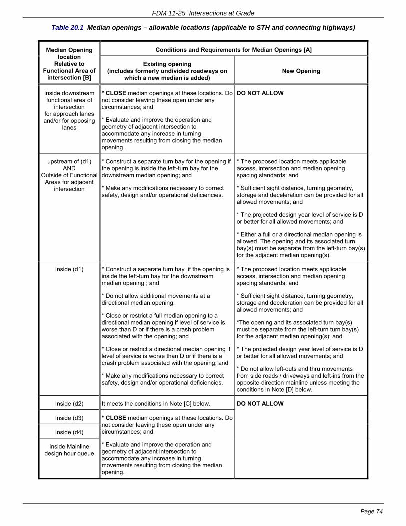
FDM 11-25 Intersections at Grade
Page 74
Table 20.1 Median openings – allowable locations (applicable to STH and connecting highways)
Median Opening location
Relative to Functional Area of
intersection [B]
Conditions and Requirements for Median Openings [A]
Existing opening (includes formerly undivided roadways on
which a new median is added) New Opening
Inside downstream functional area of
intersection for approach lanes and/or for opposing
lanes
* CLOSE median openings at these locations. Do not consider leaving these open under any circumstances; and
* Evaluate and improve the operation and geometry of adjacent intersection to accommodate any increase in turning movements resulting from closing the median opening.
DO NOT ALLOW
upstream of (d1) AND
Outside of Functional Areas for adjacent
intersection
* Construct a separate turn bay for the opening if the opening is inside the left-turn bay for the downstream median opening; and
* Make any modifications necessary to correct safety, design and/or operational deficiencies.
* The proposed location meets applicable access, intersection and median opening spacing standards; and
* Sufficient sight distance, turning geometry, storage and deceleration can be provided for all allowed movements; and
* The projected design year level of service is D or better for all allowed movements; and
* Either a full or a directional median opening is allowed. The opening and its associated turn bay(s) must be separate from the left-turn bay(s) for the adjacent median opening(s).
Inside (d1) * Construct a separate turn bay if the opening is inside the left-turn bay for the downstream median opening ; and
* Do not allow additional movements at a directional median opening.
* Close or restrict a full median opening to a directional median opening if level of service is worse than D or if there is a crash problem associated with the opening; and
* Close or restrict a directional median opening if level of service is worse than D or if there is a crash problem associated with the opening; and
* Make any modifications necessary to correct safety, design and/or operational deficiencies.
* The proposed location meets applicable access, intersection and median opening spacing standards; and
* Sufficient sight distance, turning geometry, storage and deceleration can be provided for all allowed movements; and
*The opening and its associated turn bay(s) must be separate from the left-turn turn bay(s) for the adjacent median opening(s); and
* The projected design year level of service is D or better for all allowed movements; and
* Do not allow left-outs and thru movements from side roads / driveways and left-ins from the opposite-direction mainline unless meeting the conditions in Note [D] below.
Inside (d2) It meets the conditions in Note [C] below. DO NOT ALLOW
Inside (d3) * CLOSE median openings at these locations. Do not consider leaving these open under any circumstances; and
* Evaluate and improve the operation and geometry of adjacent intersection to accommodate any increase in turning movements resulting from closing the median opening.
Inside (d4)
Inside Mainline design hour queue

FDM 11-25 Intersections at Grade
Page 75
Notes
A Evaluate each opening for both directions of travel, and for both peak and non-peak conditions. If movement restrictions or prohibitions are ineffective or impractical then close median opening.
B The upstream functional lengths for the thru lane(s), left turn bay, and right turn bay determine the boundary for the upstream functional area of intersection.
Upstream functional length of intersection elements d1, d2, d3, and d4 are independent of turn bay elements although, ideally, they correlate as shown in FDM 11-25-2, Figure 2.9. However, this correlation is not always possible, or may change because of changes in traffic at an intersection.
C Consider allowing an existing opening to remain only if there is a written request from a municipality to do so. This request must contain acceptable documentation for all of the following:
- Design alternative for closing the existing opening that evaluates alternate accesses, operations and safety and includes a good faith comparison showing that keeping the existing median opening is the preferred alternative.
- Minimum of the most recent available 3-year crash history showing that there is not a crash problem associated with the existing median opening. Crashes that might be associated with the opening can occur at the opening but also up to several hundred feet from the opening in both directions of travel. Examples include:
- Crashes involving vehicles in the approach thru lane forced to decelerate or stop because of spillback from the median opening.
- Crashes involving vehicles from a side road or driveway that are making left-out or thru movements.
- Crashes involving vehicles from the opposing lane that are making left-in or u-turn movements.
- Crashes involving vehicles unable to clear the intersection because of queuing in the opposite-direction mainline at the median opening.
- Crashes involving vehicles from the turn lane that are making left-in movements.
- The existing opening is not within the design storage queue of either the turn lane or the mainline.
- Evaluation and proposed improvements of adjacent intersections capability to accommodate increased turning movements resulting from restrictions at the existing median opening.
- There is adequate storage and deceleration length available for same-direction left-in movement at the existing median opening.
- Prohibit left-outs and thru movements from side roads / driveways and left-ins from the opposite-direction mainline unless meeting the conditions in Note [D] below.
- The design hour level of service for any of the allowed movements at the existing opening is C or better, and the design hour level of service for the intersection is C or better.
- The municipality agrees to close the opening if:
- the design hour level of service deteriorates to D or worse, or
- there is a crash problem, or
- the design storage queue for either the turn lane and/or the same-direction mainline extends into the median opening
D Movements that are prohibited during certain times of day can be allowed during other times of day if all of the following conditions are met:
- Sufficient median width and turn bay length must be available for all allowed movements.
- Levels of service for all allowed movements shall be C or better.
- Signing that prohibits these movements at all other times shall be installed.
20.5 References
1. A Policy on Geometric Design of Highways and Streets 2004, 5th edition. AASHTO, Washington, DC, 2004.
11. TRB Committee on Access Management (ed.) (ed.). Access Management Manual. Transportation Research Board, Washington, DC, 2003. 105
105 [Dec 6, 2012 email from Phyllis Barber, Transportation Research Board Publications Office / Javy Awan, Director of Publications, Transportation Research Board] The Transportation Research Board grants permission to the Wisconsin DOT to reproduce 4 figures from the TRB Access Management Manual, in a proposed revision to Chapter 11, Section 25 of Wisconsin DOT’s Facilities Development Manual, as identified in your request of December 3, 2012, subject to the following conditions: 1. Please credit as follows:

FDM 11-25 Intersections at Grade
Page 76
FDM 11-25-25 Channelization June 24, 2016
25.1 General
Traffic can be channelized by using various combinations of islands, pavement markings, rumble strips, contrasting pavement, traffic signals, etc. The design guides for providing left- and right-turn lanes (FDM 11-25-5 and FDM 11-25-10) are also methods of channelizing traffic.
25.2 Islands
This discussion assumes that islands are raised by using curb and gutter. The use of islands for directing traffic should be held to a practical minimum, as they in themselves can present problems, especially for winter maintenance activities. The desirable minimum size for islands is 150 square feet; the minimum size is 100 square feet. The approach end of the island should provide sufficient warning to identify the island's existence. This can be accomplished by using a raised delineator (non-rigid) or a rumble strip. To prevent damage to snowplows or errant vehicles, a mountable curb should be constructed on the approach nose.
Islands may also need to provide for pedestrian crossing. The crossing area needs to be unobstructed with a flat, level surface.
Minimize channelization islands, raised islands and other raised features that may inhibit turning movements of OSOW vehicles on the OSOW Truck Route (OSOW-TR).
25.2.1 Offsets
The approach nose of a curbed island needs to be conspicuous to approaching drivers - and definitely clear of the vehicle path, both visually and physically, so that drivers will not shy away from the island. Where possible, offset median islands 8 feet from the travel lane and transition to a normal curb offset, - typically 2 feet. The transition length is dependent on the design speed.
Offsets from the edge of thru travel lane to the face of a curbed channelizing island for a turning roadways are as follows (these offsets include a continuation of the width provided for on-street bicycle accommodation (see SDD 15C29)):
Low speed urban roadways (posted speed of 40 mph or less)
- If the offset to curb face from the outside edge of approach travel lane is <=2-ft then offset the approach nose of the right turn channelizing island by 4-ft from the outside edge of the travel lane and taper down to a 2-ft offset at the departure nose.
- If the offset to curb face from the outside edge of approach travel lane is >2-feet then offset the approach nose of the right turn channelizing island by an additional 2-ft from the outside edge of the travel lane and taper down to the normal offset at the departure nose.
Transitional and high speed urban roadways (posted speed of 45 mph or greater)
- If the offset to curb face from the outside edge of approach travel lane is <=6-ft then offset the approach nose of the right turn channelizing island by 8-ft from the outside edge of the travel lane and taper down to a 6-ft offset at the departure nose.
- If the offset to curb face from the outside edge of approach travel lane is >6-feet then offset the approach nose of the right turn channelizing island by an additional 2-ft from the outside edge of the travel lane and taper down to the normal offset at the departure nose.
Rural roadways
- If the outside finished shoulder width is <=6-ft then offset the approach nose of the right turn channelizing island by 8-ft from the outside edge of the travel lane and taper down to a 6-ft offset at the departure nose.
- If the outside finished shoulder width is >6-feet then offset the approach nose of the right turn channelizing island by an additional 2-ft from the outside edge of the travel lane and taper down to the normal shoulder width at the departure nose.
Offset the edge of a channelized turning roadway by 2-3 feet from the face of a curbed channelizing island at the approach nose and continue this offset to the departure nose.
From Access Management Manual, Figure 11-4, p. 207; Figure 11-5, p. 208; Figure 11-7, p. 209; and Figure 11-8, p. 210. Copyright, National Academy of Sciences, Washington, D.C., 2003. Reproduced with permission of the Transportation Research Board. 2. None of this material may be presented to imply endorsement by TRB of a product, method, practice, or policy.
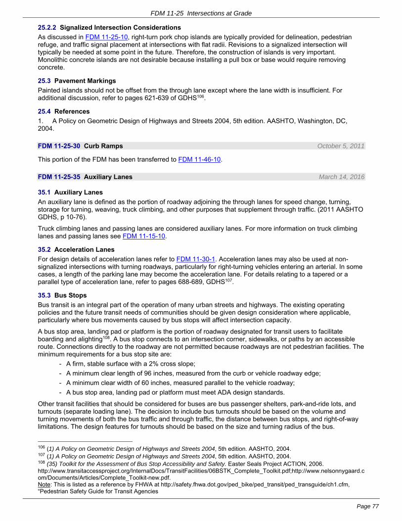
FDM 11-25 Intersections at Grade
Page 77
25.2.2 Signalized Intersection Considerations
As discussed in FDM 11-25-10, right-turn pork chop islands are typically provided for delineation, pedestrian refuge, and traffic signal placement at intersections with flat radii. Revisions to a signalized intersection will typically be needed at some point in the future. Therefore, the construction of islands is very important. Monolithic concrete islands are not desirable because installing a pull box or base would require removing concrete.
25.3 Pavement Markings
Painted islands should not be offset from the through lane except where the lane width is insufficient. For additional discussion, refer to pages 621-639 of GDHS106.
25.4 References
1. A Policy on Geometric Design of Highways and Streets 2004, 5th edition. AASHTO, Washington, DC, 2004.
FDM 11-25-30 Curb Ramps October 5, 2011
This portion of the FDM has been transferred to FDM 11-46-10.
FDM 11-25-35 Auxiliary Lanes March 14, 2016
35.1 Auxiliary Lanes
An auxiliary lane is defined as the portion of roadway adjoining the through lanes for speed change, turning, storage for turning, weaving, truck climbing, and other purposes that supplement through traffic. (2011 AASHTO GDHS, p 10-76).
Truck climbing lanes and passing lanes are considered auxiliary lanes. For more information on truck climbing lanes and passing lanes see FDM 11-15-10.
35.2 Acceleration Lanes
For design details of acceleration lanes refer to FDM 11-30-1. Acceleration lanes may also be used at non-signalized intersections with turning roadways, particularly for right-turning vehicles entering an arterial. In some cases, a length of the parking lane may become the acceleration lane. For details relating to a tapered or a parallel type of acceleration lane, refer to pages 688-689, GDHS107.
35.3 Bus Stops
Bus transit is an integral part of the operation of many urban streets and highways. The existing operating policies and the future transit needs of communities should be given design consideration where applicable, particularly where bus movements caused by bus stops will affect intersection capacity.
A bus stop area, landing pad or platform is the portion of roadway designated for transit users to facilitate boarding and alighting108. A bus stop connects to an intersection corner, sidewalks, or paths by an accessible route. Connections directly to the roadway are not permitted because roadways are not pedestrian facilities. The minimum requirements for a bus stop site are:
- A firm, stable surface with a 2% cross slope;
- A minimum clear length of 96 inches, measured from the curb or vehicle roadway edge;
- A minimum clear width of 60 inches, measured parallel to the vehicle roadway;
- A bus stop area, landing pad or platform must meet ADA design standards.
Other transit facilities that should be considered for buses are bus passenger shelters, park-and-ride lots, and turnouts (separate loading lane). The decision to include bus turnouts should be based on the volume and turning movements of both the bus traffic and through traffic, the distance between bus stops, and right-of-way limitations. The design features for turnouts should be based on the size and turning radius of the bus.
106 (1) A Policy on Geometric Design of Highways and Streets 2004, 5th edition. AASHTO, 2004. 107 (1) A Policy on Geometric Design of Highways and Streets 2004, 5th edition. AASHTO, 2004. 108 (35) Toolkit for the Assessment of Bus Stop Accessibility and Safety. Easter Seals Project ACTION, 2006. http://www.transitaccessproject.org/InternalDocs/TransitFacilities/06BSTK_Complete_Toolkit.pdf;http://www.nelsonnygaard.com/Documents/Articles/Complete_Toolkit-new.pdf. Note: This is listed as a reference by FHWA at http://safety.fhwa.dot.gov/ped_bike/ped_transit/ped_transguide/ch1.cfm, “Pedestrian Safety Guide for Transit Agencies
FDM 11-25 Intersections at Grade
Page 78
Generally, turning radii should be such that buses can remain in the outer lane during the full turn. For a more complete discussion of bus considerations, see pages 367-373, GDHS109.
FDM 11-25-40 Railroad Crossings March 31, 2017
40.1 General
If there is a railroad crossing on a project, include the region railroad coordinator early in project scoping and thereafter during project design.
FDM 17-60-5 establishes railroad grade crossing design criteria. FDM 17-40-5 explains factors to consider when evaluating the potential need for a grade separation structure. All signing, marking, signals, and gate installations shall conform to the Manual on Uniform Traffic Control Devices, FHWA, 2000 and the Wisconsin Supplement. Additional information can be found on pages 731-739, GDHS110
Sight distance triangles should be provided for vehicles approaching a crossing, but a separate sight distance triangle must be provided for vehicles such as buses and trucks, which are required to stop. Stopped vehicles need additional sight distance to proceed safely across a railroad crossing. An additional lane should be considered for stopped vehicles, particularly on multi-lane highways.
On new construction, reconstruction and pavement replacement projects being designed with Civil 3D software and using a 3D model check the 5-axle expandable-deck lowboy (DST Lowboy) OSOW-ST vehicle at railroad crossings on the OSOW Truck Route (OSOW-TR) to ensure sufficient vehicle body clearance so that vehicles can cross the tracks without “hanging up”. See FDM 11-25-1.4 for information on the OSOW-TR. See FDM 11-25-2.1.1 and Attachment 2.1 for information on OSOW vehicles.
Consult with the Region Railroad Coordinator along with the State Grade Crossing Safety Engineer and Bureau of Highway Maintenance early in the design process to address overhead railroad signal clearance along the OSOW High Clearance Routes. The Department’s goal is to provide a minimum vertical clearance of 20’-0” at railroad crossings along these routes.
40.2 References
1. A Policy on Geometric Design of Highways and Streets 2004, 5th edition. AASHTO, Washington, DC, 2004.
FDM 11-25-45 Frontage Roads March 4, 2013
A service road (also commonly referred to as a frontage or backage road) is a public or private street or road that runs generally parallel to but is separated from the major roadway by a physical barrier. Its primary function is to provide access to the abutting properties. Service roads are also referred to commonly as frontage or backage roads.
A frontage road is a service road between the right-of-way of the major roadway and the front building setback line. It provides access to properties while separating them from the principal roadway. Frontage roads will “front” on the major roadway.
A backage road is a service road that is separated from the major roadway by intervening land uses. The arterial abuts the rear lot line and buildings may face the backage road. Buildings on backage roads face away from the major roadway.
Freeway/expressway interchange areas that have frontage road access to the crossroad outside the ramps are addressed in FDM 11-5-5.
Service roads provide the following benefits:
- Effectively control access to the through lanes on the arterial street,
- Provide access to adjoining property,
- Separate local traffic from through traffic, and
- Permit circulation of local traffic adjacent to the arterial.
From an operational and safety standpoint, one-way service roads on each side of an arterial may be preferred to two-way service roads.
Maximize the separation distance between the service road/crossroad intersection and the arterial/crossroad
109 (1) A Policy on Geometric Design of Highways and Streets 2004, 5th edition. AASHTO, 2004. 110 (1) A Policy on Geometric Design of Highways and Streets 2004, 5th edition. AASHTO, 2004.

FDM 11-25 Intersections at Grade
Page 79
intersection to ensure sufficient storage for traffic on the crossroad between the service road and the arterial. At some time the arterial/crossroad intersection may be signalized or include a roundabout. Provide adequate storage for queued vehicles.
The absolute minimum separation distance (Dimension A in Figure 45.1) is 150 feet in a tightly constrained urban environment with low crossroad traffic volumes. This is the shortest length for placing signs and other traffic control devices. Greater distances are needed to provide adequate vehicle storage and to separate operation of the two intersections. Spacing of at least 300-feet, preferably more, in urban areas enables turning movements to be made from the arterial lanes onto the service road without seriously disrupting arterial traffic. High crossroad traffic volumes with high service road volumes will typically justify a greater separation distance. This may be achieved by taking the service road around an existing or proposed development as shown in the “bulbed separation” area, in effect developing a backage road for that portion of the otherwise frontage road. A greater separation than those shown in Figure 45.1 may be needed if signalization is required. The recommended separation distance between signals is about 1,300 feet, unless the signals are coordinated like the close spacing between interchange ramps. The separation between properly designed roundabouts may be 300 feet or less in tight situations.
Away from the arterial intersection consider the distance separating the service road travel lanes from the arterial travel lanes, distance “B” on the bulbed separation” side of Figure 45.1. Headlight glare, driver confusion about the location of an approaching vehicle and errant vehicles are safety concerns that suggest keeping that distance as wide as practical. In tight built-up urban areas, this distance may be as low as 45 feet. In situations that present a safety concern, glare fence or other protective shielding may be required between the service road and the arterial.
Min. Distance A111 (stop control)
Crossroad Design year AADT
Distance (ft)
Urban Rural
< 100 150 300
100 – 1,000 300 300
> 1,000 600 600
111 (36) NCHRP Report 420: Impacts of Access Management Techniques. TRB, National Research Council, 1999. http://www.accessmanagement.info/pdf/420NCHRP.pdf., pp.121-127 (1) A Policy on Geometric Design of Highways and Streets 2004, 5th edition. AASHTO, 2004., pp.725-728
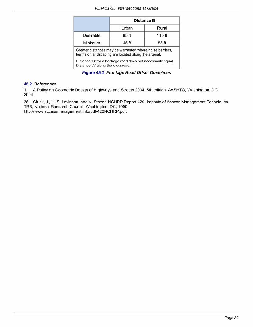
FDM 11-25 Intersections at Grade
Page 80
Distance B
Urban Rural
Desirable 85 ft 115 ft
Minimum 45 ft 85 ft
Greater distances may be warranted where noise barriers, berms or landscaping are located along the arterial.
Distance ‘B’ for a backage road does not necessarily equal Distance ‘A’ along the crossroad.
Figure 45.1 Frontage Road Offset Guidelines
45.2 References
1. A Policy on Geometric Design of Highways and Streets 2004, 5th edition. AASHTO, Washington, DC, 2004.
36. Gluck, J., H. S. Levinson, and V. Stover. NCHRP Report 420: Impacts of Access Management Techniques. TRB, National Research Council, Washington, DC, 1999. http://www.accessmanagement.info/pdf/420NCHRP.pdf.

FDM 11-25 Intersections at Grade
Page 81
FDM 11-25-50 Master Reference List112 113 114 115 116 March 4, 2013
1. [Ref 350] A Policy on Geometric Design of Highways and Streets 2004, 5th edition. AASHTO, Washington, DC, 2004.
2. [Ref 721] ORDOT Highway Design Manual ch. 9.0: Intersection and Interchange Design. Oregon Department of Transportation, 2008. ftp://ftp.odot.state.or.us/techserv/roadway/web_drawings/HDM/Rev_E_2003Chp09.pdf. Accessed 8-6-2010.
3. [Ref 698] Maze, T. H., J. L. Hochstein, R. R. Souleyrette, CTRE - Iowa State University, H. Preston, and R. Storm. NCHRP Report 650: Median Intersection Design for Rural High-Speed Divided Highways. Transportation Research Board of the National Academies, Washington, DC, 2010. http://onlinepubs.trb.org/onlinepubs/nchrp/nchrp_rpt_650.pdf. Accessed 5-18-2010.
4. [Ref 455] Harwood, D. W., M. T. Pietrucha, M. D. Wooldridge, R. E. Brydia, and K. Fitzpatrick. NCHRP Report 375: Median Intersection Design. TRB, National Research Council, Washington, DC, 1995.
5. [Ref 294] Potts, I. B., D. W. Harwood, D. J. Torbic, K. R. Richard, J. S. Gluck, H. S. Levinson, P. M. Garvey, and R. S. Ghebrial. NCHRP Report 524: Safety of U-Turns at Unsignalized Median Openings. Transportation Research Board of the National Academies, Washington, DC, 2004. http://onlinepubs.trb.org/Onlinepubs/nchrp/nchrp_rpt_524.pdf.
6. [Ref 442] Eyler, D. Innovative Intersection Designs. (DRAFT PowerPoint presentation for 2009 ACEC/WisDOT Transportation Improvement Conference). SRF Consulting Group, Inc., Plymouth, MN, Feb. 25, 2009.
7. [Ref 719] Florida Intersection Design Guide. Florida DOT, 2007. http://www.dot.state.fl.us/rddesign/FIDG-
112 [Dec 3, 2012 email from Ellen Chafee, Editor, CRP-TRB] The TRB through the National Academy of Sciences (NAS) grants permission to use the material listed below from Maze et al. (2010) NCHRP Report 650:Median Intersection Design for Rural High-Speed Divided Highways and J. A. Bonneson and M. D. Fontaine (2001) NCHRP Report 457: Engineering Study Guide for Evaluating Intersection Improvements in a proposed revision to Chapter 11, Section 25 of Wisconsin DOT’s Facilities Development Manual (FDM 11-25). NCHRP Report 650 Table 19 p. 47 NCHRP Report 650 Figure 117 p. 148 NCHRP Report 650 Figure 31 p. 49 NCHRP Report 650 Figure 65 p. 86 NCHRP Report 650 Figure 48 p. 65 NCHRP Report 457 Figure 2.6 p. 23 NCHRP Report 457 Figure 2-6.xls Interactive spreadsheet in online version Permission is also granted for any subsequent versions of the Work, including versions made for use with blind or physically handicapped persons, and all foreign-language translations of the Work prepared for distribution throughout the world. Permission is given with the understanding that inclusion of the material will not be used to imply Transportation Research Board, AASHTO, Federal Highway Administration, Transit Development Corporation, Federal Transit Administration, Federal Aviation Administration, or Federal Motor Carriers Safety Administration endorsement of a particular product, method, or practice. Permission is also provided on condition that appropriate acknowledgment will be given as to the source material. 113 [Aug 17, 2004 email from Javy Awan, Director of Publications, Transportation Research Board] TRB references are reproduced with permission of the Transportation Research Board, From Access Management Manual, Transportation Research Board, National Research Council, Washington, D.C., 2003 114 [Dec 6, 2012 email from Phyllis Barber, Transportation Research Board Publications Office / Javy Awan, Director of Publications, Transportation Research Board] The Transportation Research Board grants permission to the Wisconsin DOT to reproduce 4 figures from the TRB Access Management Manual, in a proposed revision to Chapter 11, Section 25 of Wisconsin DOT’s Facilities Development Manual, as identified in your request of December 3, 2012, subject to the following conditions: 1. Please credit as follows: From Access Management Manual, Figure 11-4, p. 207; Figure 11-5, p. 208; Figure 11-7, p. 209; and Figure 11-8, p. 210. Copyright, National Academy of Sciences, Washington, D.C., 2003. Reproduced with permission of the Transportation Research Board. 2. None of this material may be presented to imply endorsement by TRB of a product, method, practice, or policy. 115 [Dec 5, 2012 email and attached letter from Zach Pleasant, Information Services Director, ITE] The Institute of Transportation Engineers grants permission to use Figures 6-19, P6-27 and 6-20, P6-30 from Transportation and Land Development, 2nd Edition for the Wisconsin DOT’s Facilities Development Manual (FDM 11-25). Please know that this is a one-time, one-use agreement, and any other use of this material or any other resource of ITE must be requested and approved in writing. Please acknowledge our copyright by publishing: © 2012 Institute of Transportation Engineers, 1627 Eye Street, NW, Suite 600, Washington, DC 20006 USA, www.ite.org. Used by permission. 116 See footnote after reference no. 3 above [Dec 3, 2012 email from Ellen Chafee, Editor, CRP-TRB]
FDM 11-25 Intersections at Grade
Page 82
Manual/FIDG2007.pdf. Accessed 8-6-2010.
8. [Ref 723] MADOT Highway Department Project Development & Design Guide ch. 6: Intersection Design. Massachusetts Department of Transportation - Highway Division, 2006. http://www.mhd.state.ma.us/downloads/designGuide/CH_6_a.pdf. Accessed 7-27-2010.
9. [Ref 659] ILDOT Bureau of Design and Environment Manual ch. 36: Intersections. Illinois DOT, 2002. http://www.dot.state.il.us/desenv/BDE%20Manual/BDE/pdf/chap36.pdf. Accessed 1-8-2010.
10. [Ref 239] NYSDOT Highway Design Manual ch. 5: Basic Design. New York State DOT, Albany, NY, 2006. https://www.nysdot.gov/portal/page/portal/divisions/engineering/design/dqab/hdm/hdm-repository/chapt_05.pdf. Accessed 8-6-2010.
11. [Ref 228] TRB Committee on Access Management (ed.) (ed.). Access Management Manual. Transportation Research Board, Washington, DC, 2003.
12. [Ref 647] Stover, V. G. and F. J. Koepke. Transportation and Land Development, 2nd edition. Institute of Transportation Engineers, Washington, DC, 2006.
13. [Ref 648] Bonneson, J. A. and M. D. Fontaine. NCHRP Report 457: Engineering Study Guide for Evaluating Intersection Improvements. TRB, National Research Council, Washington, DC, 2001. http://onlinepubs.trb.org/onlinepubs/nchrp/esg/esg.pdf.
14. [Ref 718] Manual on Uniform Traffic Control Devices. Federal Highway Administration, Washington, DC, 2009.
15. [Ref 406] Gattis, J. L. and S. T. Low. Intersection Angle Geometry and the Driver's Field of View. In Transportation Research Record 1612: Highway Geometric Design Issues. TRB, National Research Council, Washington, DC, 1998, pp. 10-16.
16. [Ref 510] Staplin, L. K., K. Lococo, S. R. Byington, and Scientex Corporation. Highway Design Handbook for Older Drivers and Pedestrians. FHWA-RD-01-103. Federal Highway Administration Turner-Fairbank Highway Research Center, McClean, VA, May, 2001. http://www.tfhrc.gov/humanfac/01103/coverfront.htm. Accessed 4-2-2009.
17. [Ref 41] Staplin, L., K. Lococo, S. Byington, D. Harkey, and FHWA. Guidelines and Recommendations to Accommodate Older Drivers and Pedestrians. FHWA-RD-01-051. Federal Highway Administration, McLean, VA, May, 2001. http://www.tfhrc.gov/humanfac/01105/cover.htm. Accessed 3-16-2006.
18. [Ref 409] Staplin, L., K. Lococo, and S. Byington. Older Driver Highway Design Handbook [ch.1 - Intersections (At-Grade)]. FHWA-RD-97-135. Federal Highway Administration, Washington, DC, Jan., 1998. http://www.tfhrc.gov/safety/pubs/97135/index.htm#intro. Accessed 2-3-2009.
19. [Ref 405] Rural Intersections - Turn lanes - Left-Turn Bypass Lanes. In MNDOT Road Design Manual ch. 5: At-Grade Intersections. Minnesota DOT, 2000, sect. 5-4.01.04, pp. 5-4(2). http://www.dot.state.mn.us/design/rdm/english/5e.pdf. Accessed 2-3-2009.
20. [Ref 807] Baumann, A. J. Minimum Required Turn Lane Storage Lengths & Tapers For Left & Right Turn Lanes At Signalized & Non-signalized Intersections. (DRAFT). Wisconsin DOT, Feb. 25, 2010 current revision (created Dec 2, 2008; previously revised: Nov 4, 2009).
21. [Ref 312] FHWA Resource Center Safety and Design Team. Review of Wisconsin Bypass Road Design Practices February 13-14, 2006. (Final). Federal Highway Administration Resource Center, Olympia Fields, IL, 2006. http://www.dot.wisconsin.gov/library/publications/docs/wis-bypass-report.pdf. Accessed 4-2-2009.
22. [Ref 368] Rationale for Median Type Recommendations. Kentucky Transportation Cabinet, 2008. http://www.planning.kytc.ky.gov/congestion/medians/Median%20Type%20Guidelines.pdf. Accessed 5-3-2012.
23. [Ref 804] A Policy on Geometric Design of Highways and Streets 2011, 6th edition. AASHTO, Washington, DC, 2011. www.transportation.org.
24. [Ref 624] Highway Capacity Manual 2010, 5th edition. Transportation Research Board of the National Academies, Washington, DC, 2010.
25. [Ref 808] Revello, B. Two Way Left Turn Lane (TWLTL). Wisconsin DOT, Nov. 26, 2007.
26. [Ref 815] Geometric Design of Lanes - Continuous Two-Way Left-Turn Lanes (TWLTLs). In IADOT Design Manual ch. 6: Geometric Design. Iowa DOT, 2001, sect. 6C-6, pp. 1-4. http://www.iowadot.gov/design/dmanual/06c-06.pdf. Accessed 5-3-2012.
27. [Ref 814] Facility Selection / Two - Way Left - Turn Lanes. In MODOT Engineering Policy Guide ch. 200:

FDM 11-25 Intersections at Grade
Page 83
Geometrics. Missouri DOT, 2012, sect. 232.3. http://epg.modot.org/index.php?title=232.3_Two_-_Way_Left_-_Turn_Lanes. Accessed 5-3-2012.
28. [Ref 825] Ackeret, K. W. Criteria for the Geometric Design of Triple Left-Turn Lanes. ITE Journal, vol. 64, no. 12, 1994 December, pp. 27-33. http://turnlanes.net/files/criteria_for_the_geometric_design_of_triple_left-turn_lanes.pdf. Accessed 7-24-2012.
29. [Ref 824] Rodegerdts, L. A., B. Nevers, B. Robinson, J. Ringert, P. Koonce, J. Bansen, T. Nguyen, J. McGill, D. Stewart, J. Suggett, T. Neuman, N. Antonucci, K. Hardy, and K. Courage. Individual Movement Treatments / Multiple Left-Turn Lanes. In FHWA-HRT-04-091: Signalized Intersections: Informational Guide. Federal Highway Administration Turner-Fairbank Research Center, McLean, VA, 2004, ch. 12.1.2, pp. 318-319. http://www.tfhrc.gov/safety/pubs/04091/04091.pdf. Accessed 8-6-2007.
30. [Ref 827] Courage, K., A. Gan, B. Stephens, M. Willis, and University of Florida Transportation Research Center. Triple Left Turn Lanes At Signalized Intersections. BC131 (FINAL). Florida DOT, Tallahassee, FL, Dec., 2002. http://www.dot.state.fl.us/research-center/Completed_Proj/Summary_TE/FDOT_BC131rpt.pdf. Accessed 7-30-2012.
31. [Ref 828] NYSDOT Highway Design Manual ch. 5: Basic Design. New York State DOT, Albany, NY, 2011. https://www.dot.ny.gov/divisions/engineering/design/dqab/hdm/hdm-repository/chapt_5_final.pdf. Accessed 7-30-2012.
32. [Ref 339] OHDOT Location & Design Manual, Vol.1, Roadway Design ch.400: Intersection Design. Ohio DOT, 2006. http://www.dot.state.oh.us/roadwayengineering/standards/Publications/LDM/2006-07-21/400_jul06.pdf.
33. [Ref 823] Cooner, S. A., S. E. Ranft, Y. K. Rathod, Y. Qi, L. Yu, Y. Wang, and S. Chen. Development of Guidelines for Triple Left and Dual Right-Turn Lanes: Technical Report. FHWA/TX-11/0-6112-1. Texas Transportation Institute, Texas A&M University, College Station, TX, Jan., 2011 Published July 2011. http://tti.tamu.edu/documents/0-6112-1.pdf. Accessed 7-24-2012.
34. [Ref 833] Yi, Q., C. Xiaoming, D. Li, and Center for Transportation Training and Research - Texas Southern University. Development of Warrants for Installation of Dual Right-Turn Lanes at Signalized Intersections. SWUTC/12/161141-1. Texas Transportation Institute, Texas A&M University, College Station, TX, Apr., 2012. http://d2dtl5nnlpfr0r.cloudfront.net/swutc.tamu.edu/publications/technicalreports/161141-1.pdf. Accessed 1-9-2013.
35. [Ref 829] Weiner, R., and Nelson\Nygaard Consulting Associates Inc. Toolkit for the Assessment of Bus Stop Accessibility and Safety. Easter Seals Project ACTION, Washington, DC, 2006. http://www.transitaccessproject.org/InternalDocs/TransitFacilities/06BSTK_Complete_Toolkit.pdf;http://www.nelsonnygaard.com/Documents/Articles/Complete_Toolkit-new.pdf. Accessed 8-16-2012.
36. [Ref 495] Gluck, J., H. S. Levinson, and V. Stover. NCHRP Report 420: Impacts of Access Management Techniques. TRB, National Research Council, Washington, DC, 1999. http://www.accessmanagement.info/pdf/420NCHRP.pdf.