FD SERIES SCALES SERVICE MANUAL - Test Equipment DepotFD3 1 kg, 2 kg, 3 kg 1 or 2 kg & 3 kg 1 kg & 3...
48
FD SERIES SCALES SERVICE MANUAL 99 Washington Street Melrose, MA 02176 Phone 781-665-1400 Toll Free 1-800-517-8431 Visit us at www.TestEquipmentDepot.com
Transcript of FD SERIES SCALES SERVICE MANUAL - Test Equipment DepotFD3 1 kg, 2 kg, 3 kg 1 or 2 kg & 3 kg 1 kg & 3...

FD SERIES SCALES
SERVICE MANUAL
99 Washington Street Melrose, MA 02176 Phone 781-665-1400Toll Free 1-800-517-8431
Visit us at www.TestEquipmentDepot.com

The information contained in this manual is believed to be accurate at the time of publication,but Ohaus Corporation assumes no liability arising from the use or misuse of this material.Reproduction of this material is strictly prohibited.
Material in this manual is subject to change.
© Copyright 2004 Ohaus Corporation, all rights reserved.® Registered trademark of Ohaus Corporation.
FD SERIES SCALESSERVICE MANUAL


i
TABLE OF CONTENTS
CHAPTER 1 INTRODUCTION Page
1. Introduction ......................................................... ................................................. .1-11.1 Service Facilities ...................................................................................................... .1-11.2 Tools and Equipment ............................................................................................... .1-2
1.2.1 Standard Tools and Test Equipment ................................................................. .1-21.2.2 Special Tools................................................................................................ .1-2
1.3 Calibration Masses Required ..................................................................................... .1-21.4 Service Strategy ....................................................................................................... .1-3
CHAPTER 2 DIAGNOSIS2. Diagnosis ........................................................................................................... .2-12.1 Scale Setup and Examination .................................................................................... .2-12.2 Preliminary Checks .................................................................................................. .2-12.3 Troubleshooting Tables ............................................................................................. .2-12.4 FD Series Scales Error Code Table............................................................................... .2-5
CHAPTER 3 SCALE TESTING AND CALIBRATION3. Testing and Calibration ............................................................................................. .3-13.1 Testing the AC Adapter .............................................................................................. .3-13.2 Testing the Membrane Switch .................................................................................... .3-13.3 Testing the Load Cell Assembly .................................................................................. .3-2
3.3.1 Ramp Test .................................................................................................... .3-23.3.2 Resistance Test ............................................................................................. .3-23.3.3 Excitation and Output Voltage Test .................................................................. .3-2
3.4 Testing the Main PC Board ........................................................................................ .3-43.4.1 Main PC Board Voltage Measurements ............................................................. .3-43.4.2 Simulator Testing .......................................................................................... .3-5
3.5 Testing the Battery .................................................................................................... .3-63.5.1 Precautions for Battery Handling ..................................................................... .3-63.5.2 Battery Tests ................................................................................................. .3-6
3.6 Performance Tests .................................................................................................... .3-83.6.1 Segment Display Test .................................................................................... .3-83.6.2 Repeatability Test .......................................................................................... .3-83.6.3 Off-Center Load Test ..................................................................................... .3-103.6.4 Linearity Test ............................................................................................... .3-11
3.7 Specifications ......................................................................................................... .3-123.8 Calibration .......................................................................................................... .3-13
3.8.1 Calibration Points ........................................................................................ .3-133.8.2 Span Calibration .......................................................................................... .3-133.8.3 Linearity Calibration ..................................................................................... .3-14
3.9 Menu .....................................................................................................................................3-143.91 Menu Structure..........................................................................................................3-14

ii
CHAPTER 4 REPAIR PROCEDURES4. Repair Procedures .................................................................................................... .4-14.1 Removing Top Housing ............................................................................................ .4-14.2 Replacing the Membrane Switch ................................................................................ .4-24.3 Main PC Board/LCD Replacement ............................................................ ................. .4-3
4.3.1 Main PC Board Replacement .......................................................................... .4-34.3.2 LCD Replacement .......................................................................................... .4-4
4.4 Replacing the Load Cell Assembly (with frame) ........................................................... .4-54.5 Replacing the Load Cell Component ........................................................................... .4-6
4.5.1 Overload Protection Stop Adjustment ......................................................... ...... .4-64.6 Replacing the Battery ............................................................................................... .4-7
CHAPTER 5 PARTS LISTS5. Parts Lists ........................................................................................................... .5-15.1 FD Series Scales Exploded View ................................................................................. .5-2
APPENDIX A SERVICE MENUA. Introduction ........................................................................................................... .A-1A.1 Entering Service Menu .............................................................................................. .A-1A.2 Navigation ........................................................................................................... .A-1A.3 Capacity ........................................................................................................... .A-1A.4 Geographical Adjustment Factor ................................................................................ .A-2A.5 Service Calibration ................................................................................................... .A-2A.6 Ramp ..............................................................................................................A.3

iii
TABLE OF CONTENTS (Cont.)
LIST OF TABLES
TABLE NO. TITLE PAGE1-1 Calibration Masses ............................................................................. 1-22-1 Scale Will Not Turn On With AC Adapter ................................................. 2-12-2 Scale Will Not Turn On Using Battery Power ........................................... 2-22-3 Scale Does Not Respond To Front Panel Controls .................................... 2-32-4 No Display or Partial Display ............................................................... 2-32-5 Balance Readings Incorrect or Unstable ................................................. 2-42-6 Cannot Calibrate the Scale ................................................................... 2-42-7 FD Series Scales Error Codes ................................................................ 2-53-1 Load Cell Resistance Readings ............................................................ 3-23-2 Load Cell Output Readings .................................................................. 3-33-3 Battery Capacity ................................................................................. 3-73-4 Specifications .................................................................................. 3-123-5 Calibration Points ............................................................................. 3-133-6 Menu Structure ................................................................................. 3-144-1 Load Cell Screw Torque Information ...................................................... 4-64-2 Load Cell Overload Protection Stop Gap settings .................................... 4-75-1 FD Series Scales Parts List ................................................................... 5-3A-1 Geographical Adjustment Values .......................................................... A-4
LIST OF ILLUSTRATIONS
FIGURE NO. TITLE PAGE3-1 FD Series Scales Membrane Switch Wiring Diagram................................ 3-13-2 FD Series Scales Interconnection Diagram ............................................. 3-33-3 Segment Display ................................................................................ 3-83-4 Standard Deviation Worksheet .............................................................. 3-93-5 Calculation of Standard Deviation ........................................................ 3-93-6 Sample Calculation of Standard Deviation ........................................... 3-103-7 Off-Center Load Test Weight Locations ................................................ 3-103-8 Security Switch Shown in On Position ................................................. 3-153-9 Sealing Methods .............................................................................. 3-154-1 Top Housing Retaining Screw Locations ................................................ 4-14-2 Connector Locations ........................................................................... 4-34-3 Load Cell Retaining Screws .................................................................. 4-55-1 Exploded View of FD Series Scales ........................................................ 5-2A-1 Service Menu Diagram ........................................................................ A-1

iv

1-1
CHAPTER 1 INTRODUCTION
1. INTRODUCTIONThis service manual contains instructions for the diagnosis and repair work to be performed by OhausDealers or Ohaus authorized service centers. Knowledge of the operation of the Scale is assumed.Instruction manuals may be required with this service manual. For complete information on operation,refer to the Instruction Manual.
This manual covers maintenance on the following:FD Series Scales, Models FD3, FD6 and FD15
The contents of this manual are contained in five chapters and an Appendix with service menu instructions.
Chapter 1 Introduction - Contains information about service facilities, tools, test equipment, test masses,and service strategy.
Chapter 2 Diagnosis - Contains information on problem verification, scale examination, preliminarychecks and troubleshooting tables.
Chapter 3 Testing - Contains testing procedures, interconnection diagrams and wiring diagrams,performance tests, specifications and calibration.
Chapter 4 Repair Procedures - Contains detailed repair procedures for all major components.
Chapter 5 Parts Lists - Contains an exploded view identifying all serviceable replacement componentswith associated parts lists.
Appendix A Service Menu - Contains Capacity, Geographical Code, Service Calibration and Rampinformation for the FD Series Scales in a service mode.
1.1 SERVICE FACILITIESThe service area should be a stable environment.
The bench area should be clean and should contain an antistatic mat with a personnel-grounding clipto protect internal circuit boards. The ideal electrical power source for the scales should be a dedicatedline to avoid sudden fluctuations or voltage drops caused by external equipment drawing heavy current.
The service area for the scales should be away from direct sunlight, overhead heating or air conditioningducts, magnetic fields such as motors, large transformers or vibrating sources such as machinery.
The power outlet should be grounded for safety. Sufficient space should be provided around the scale asnot to be affected by other equipment. This will ensure that the scale is operated under ideal conditions.

1-2
CHAPTER 1 INTRODUCTION1.2 TOOLS AND EQUIPMENT
1.2.1 Standard Tools and Test EquipmentThe service shop should contain the following equipment:1. Digital Voltmeter (DVM).2. Standard Electronics tool kit.3. Desk magnifier on a stand.4. Grounding mat and clip.5. Razor blades.
1.2.2 Special ToolsTo service the Ohaus FD Series Scales, the following equipment is recommended:
1. A Load Cell Simulator.2. AC Adapter, 120 V, 60 Hz (US) Ohaus P/N 805004353. AC Adapter, 220 V, 60 Hz (US) Ohaus P/N 805005214. AC Adapter, 230 V, 50 Hz (EU) Ohaus P/N 805004365. AC Adapter, 230 V, 50 Hz (UK) Ohaus P/N 805004376. AC Adapter, 240 V, 50 Hz (AU) Ohaus P/N 805004627. AC Adapter, 100 V, 50 Hz (JP) Ohaus P/N 71143794
NOTE: Adapters required for servicing are location dependent.
1.3 CALIBRATION MASSES REQUIREDThe masses required to test the FD Series Scales must meet the requirements of ASTM Class 4 or OIMLClass F2. The mass values are listed in Table 1-1. Bolded values are default settings.
TABLE 1-1. CALIBRATION MASSES
MODEL Span Cal Choices Linearity Cal (fixed) Service CalibrationCal in kg: Masses Totaling Masses Totaling Masses TotalingFD3 1 kg, 2 kg, 3 kg 1 or 2 kg & 3 kg 1 kg & 3 kgFD6 2 kg, 4 kg, 6 kg 2 or 4 kg & 6 kg 2 kg & 6 kgFD15 5 kg, 10 kg, 15 kg 10 kg & 15 kg 5 kg & 15 kg
1.4 SERVICE STRATEGYThe repair method for the FD Series Scales is the direct substitution of major assemblies. The availablerepair parts are listed in Table 5-1.
The FD Series Scales contains 4 major replaceable assemblies: Cover Assembly with Membrane Switch,Load Cell Assembly with Frame, Lead Acid Rechargeable Battery and the Main PC Board with LCD.
NOTE: The Load Cell, LCD and Membrane Switch may also be ordered and replaced separately.
This service manual contains sufficient information to isolate the problem, replace the component, testand restore the Scale to original factory specifications.

2-1
CHAPTER 2 DIAGNOSIS2. DIAGNOSISThis section contains information needed to properly evaluate the reported problem and diagnose itscause.
2.1 SCALE SETUP AND EXAMINATIONSet up the scale according to the Instruction manual. Allow the scale to stabilize to room temperature.Examine the scale for signs of corrosion or physical damage.
2.2 PRELIMINARY CHECKSPower up the scale using the customer’s ac adapter. In the case where the scale will not power up,check the ac adapter. Observe and record the error codes and software revision. Record all menu settingsas received.
2.3 TROUBLESHOOTING TABLESTroubleshooting tables 2-1 through 2-7 identify actual types of problems that could be encountered withthe scale.
The troubleshooting tables refer to interconnection and wiring diagrams in this section to assist in locatingthe problem.
2-1 SCALE WILL NOT TURN ON WITH AC ADAPTER.
SYMPTOMScale will not turn on with ACadapter supplied.
PROBABLE CAUSEAdapter defective.
DC input connector at thebottom of scale is defective.
Membrane Switch defective.
Main PC Board is defective.
REMEDYRefer to Section 3.1 and check the acadapter voltage output. If voltage islow or nonexistent, replace the acadapter. If OK, proceed.
Refer to Section 4.1 and open the scale.
Reconnect the ac adapter to the scale.Check dc voltage on the Main PC Boardor test points as shown in Figure 3-2.Voltage should read between 9 and 14Volts (power off), and above 9 Volts dc(power on). If voltage is not present,check and replace the Harness. If OK,proceed.
Refer to Section 3.2 and test the Mem-brane Switch. Replace if necessary.See Repair Procedure 4.2
If the scale fails to turn on with a newMembrane Switch, the Main PC Boardshould be tested in accordance withsection 3.4. The Main PC Board ifdefective should be replaced. See Re-pair Procedures 4.3. After repair, per-form Operational Tests in Section 3.6.

2-2
CHAPTER 2 DIAGNOSIS
REMEDY
Refer to Section 3.5 and test the battery.Replace if necessary. See Repair Proce-dure 4.6.
Refer to section 4.1 and open the scale.Check voltage at battery contacts first.Check dc voltage at pins 1 and 3 ofbattery connector on the Main PC Board.See Figure 3-2. Voltage should readapproximately 6 Volts dc minimum. Ifvoltage is not present at the connector,disconnect the leads from the batteryand make a continuity test between theconnectors on the Harness to connectorpins 1 and 3 on the Main PC Board.Resistance should be 0 ohms for the redlead and 0 ohms for the black lead. If anopen condition exists, replace wiring asnecessary. If OK, proceed.
Refer to Section 3.2 and test the Mem-brane Switch. Replace if necessary. SeeRepair Procedure 4.2
If the scale fails to turn on with a newMembrane Switch, the Main PC Boardshould be tested in accordance withSection 3.4. The Main PC Board if defec-tive should be replaced. See RepairProcedures 4.3. After repair, performOperational Tests in Section 3.6.
PROBABLE CAUSE
Battery discharged or de-fective.
Wiring harness defective orbattery clips connectionbroken.
Membrane Switch defec-tive.
Main PC Board is defec-tive.
SYMPTOM
Scale will not turn on usingbattery power.
TABLE 2-2 SCALE WILL NOT TURN ON USING BATTERY POWER.
2-3
CHAPTER 2 DIAGNOSIS
SYMPTOM
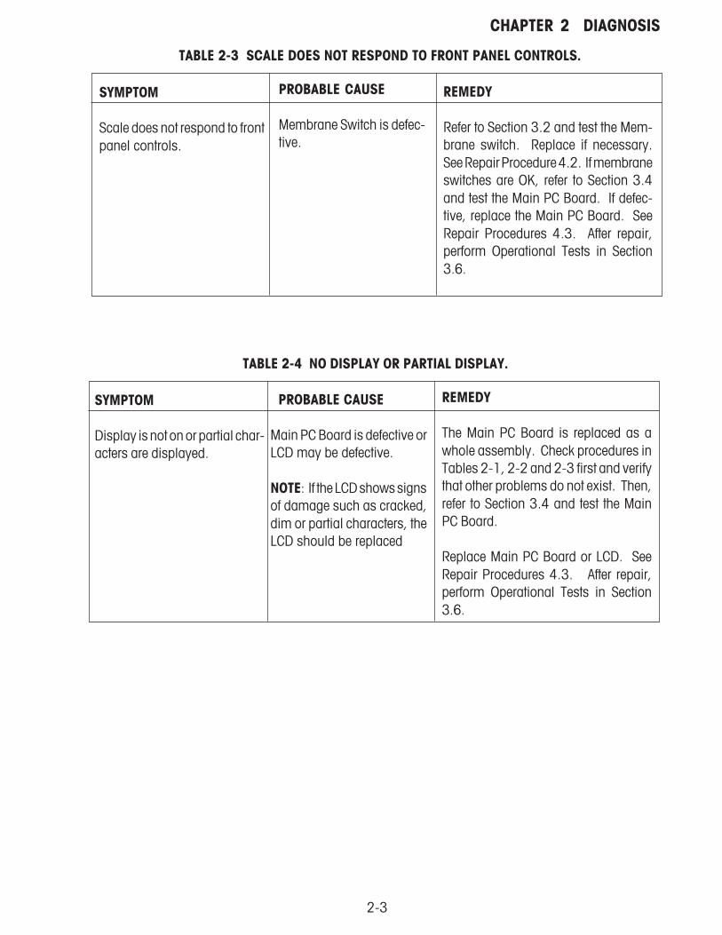
Scale does not respond to frontpanel controls.
TABLE 2-3 SCALE DOES NOT RESPOND TO FRONT PANEL CONTROLS.
PROBABLE CAUSE
Membrane Switch is defec-tive.
REMEDY
Refer to Section 3.2 and test the Mem-brane switch. Replace if necessary.See Repair Procedure 4.2. If membraneswitches are OK, refer to Section 3.4and test the Main PC Board. If defec-tive, replace the Main PC Board. SeeRepair Procedures 4.3. After repair,perform Operational Tests in Section3.6.
TABLE 2-4 NO DISPLAY OR PARTIAL DISPLAY.
SYMPTOM
Display is not on or partial char-acters are displayed.
PROBABLE CAUSE
Main PC Board is defective orLCD may be defective.
NOTE: If the LCD shows signsof damage such as cracked,dim or partial characters, theLCD should be replaced
REMEDY
The Main PC Board is replaced as awhole assembly. Check procedures inTables 2-1, 2-2 and 2-3 first and verifythat other problems do not exist. Then,refer to Section 3.4 and test the MainPC Board.
Replace Main PC Board or LCD. SeeRepair Procedures 4.3. After repair,perform Operational Tests in Section3.6.
2-4
CHAPTER 2 DIAGNOSIS
TABLE 2-5 BALANCE READING INCORRECT OR UNSTABLE.
TABLE 2-6 CANNOT CALIBRATE THE SCALE.
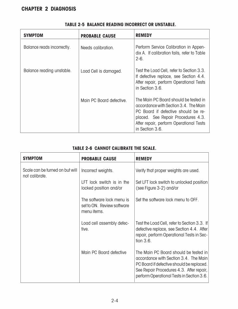
SYMPTOM
Balance reads incorrectly.
Balance reading unstable.
PROBABLE CAUSE
Needs calibration.
Load Cell is damaged.
Main PC Board defective.
REMEDY
Perform Service Calibration in Appen-dix A. If calibration fails, refer to Table2-6.
Test the Load Cell, refer to Section 3.3.If defective replace, see Section 4.4.After repair, perform Operational Testsin Section 3.6.
The Main PC Board should be tested inaccordance with Section 3.4. The MainPC Board if defective should be re-placed. See Repair Procedures 4.3.After repair, perform Operational Testsin Section 3.6.
SYMPTOM
Scale can be turned on but willnot calibrate.
PROBABLE CAUSE
Incorrect weights.
LFT lock switch is in thelocked position and/or
The software lock menu isset to ON. Review softwaremenu items.
Load cell assembly defec-tive.
Main PC Board defective
REMEDY
Verify that proper weights are used.
Set LFT lock switch to unlocked position(see Figure 3-2) and/or
Set the software lock menu to OFF.
Test the Load Cell, refer to Section 3.3. Ifdefective replace, see Section 4.4. Afterrepair, perform Operational Tests in Sec-tion 3.6.
The Main PC Board should be tested inaccordance with Section 3.4. The MainPC Board if defective should be replaced.See Repair Procedures 4.3. After repair,perform Operational Tests in Section 3.6.

2-5
CHAPTER 2 DIAGNOSIS2.4 FD SERIES SCALES ERROR CODE TABLEThe FD Series Scales is equipped with software which will display an error condition when it occurs.Review the listed codes and follow instructions to correct the problem.
TABLE 2-7. FD SERIES SCALES ERROR CODES
ERROR CODE
Error 1
Error 2
Error 9
Error 14
CAUSE
The load on the Pan exceedsthe rated capacity of the scale(Overload condition).
If the scale was turned onwith a load on the pan.
Needs calibration.
Damaged Load Cell.
Pan missing.(Underload condition.)
Needs calibration.
Damaged load cell.
Checksum error.(Configuration data.)
Needs calibration.
PCB defective.
At power up, the load cellsignal is outside the allow-able limit.(Zero range error.)
REMEDY
Remove excess load. Turn scale off thenon.
Remove excess load, cycle power off thenon.
Perform service calibration, see Appendix A.
Test the Load Cell, see Section 3.3. Ifdefective, replace, see Repair Procedures4.4. After repair, perform OperationalTests, see Section 3.6.
Replace the Pan.
Press the ON/ZERO Off button, if –No-appears, turn power to the scale off thenon. If the problem persists, perform cali-bration in Section 3.9.
If the problem still persists, refer to Table2-5 and follow the remedies under LoadCell Damaged.
See Appendix A Service Menu, check ca-pacity.
Perform service calibration, see Appendix A.
If error persists, replace PCB.
Remove load from pan, if problem per-sists, refer to Table 2- 5 and follow theremedies under Load Cell Damaged..

2-6
CHAPTER 2 DIAGNOSIS2.4 FD SERIES SCALES ERROR CODE TABLE (Cont.)The FD Series Scales is equipped with software which will display an error condition when it occurs.Review the listed codes and follow instructions to correct the problem.
TABLE 2-7. FD SERIES SCALES ERROR CODES
ERROR CODE
Error 21
CAL E
CAUSE
Checksum error.(User data menu settings.)
Corrupt checksum error(calibration).
Incorrect weight used (Cali-bration error).
Load cell damaged.
PC board damaged.
REMEDY
Check menu settings.
Perform Service calibration. See Appen-dix A Service Menu.
Calibrate using correct calibration weightsand in the correct order.
Refer to Section 3.3 and test the LoadCell. If defective, replace the load cell,see Repair Procedures 4.4 and or
Test the Main PC board refer to Section3.4. If defective, see Repair Procedure4.3. After repair, perform Operational seeSection 3.6.

3-1
CHAPTER 3 SCALE TESTING AND CALIBRATION3. TESTING AND CALIBRATIONThis section of the manual contains testing procedures of the individual replaceable components and thescale. Before and after servicing the FD Series Scales, an operational test and various performance testsshould be made to ascertain whether or not the scale meets specifications.
3.1 TESTING THE AC ADAPTERThe AC Adapters are available with different input voltages. Before testing the Adapter, make sure theAdapter rating agrees with the power source being used. All Adapters are rated with an output of 9 V dcat 500mA. Adapters can fail by having shorted internal windings producing low voltage output or nooutput at all.
1. Plug the AC Adapter in a suitable power source and measure the open circuit voltage on connectorit should be 10 V dc to 17 V dc.
2. Perform procedure Section 4.1 and remove Top Housing. Plug the AC Adapter into the scale andmeasure the test points for the AC connector, see Figure 3-2. The output voltage should be 9Volts dc minimum, and 14 Volts dc maximum. If the voltage is below or above these readings,replace the Adapter.
3.2 TESTING THE MEMBRANE SWITCHThe Membrane switch can be tested after removing the Top Housing from the Base Housing.
1. Refer to Section 4.1 and remove the Top Housing.
2. Refer to Figure 3-1. Using an Ohmmeter, measure the resistance between pin 5 to all other pinson the membrane switch cable, the readings should be infinite resistance. Then, press each buttonand check that the resistance is zero for each button. If continuity is not present, the membraneswitch is defective. Replace the Membrane Switch.
3. Check that the Membrane Switch is not shorted to the Top Housing case. Check pins 1 through5 to the case which should be infinite resistance.
4. Reassemble Top Housing to Base Housing.
Figure 3-1. FD Series Scales Membrane Switch Wiring Diagram.
3-2
CHAPTER 3 SCALE TESTING AND CALIBRATION3.3 TESTING THE LOAD CELL ASSEMBLYThis section contains three methods of testing the Load cell.
3.3.1 Ramp TestRefer to Appendix A and perform the Ramp Test. If the Ramp Test passes, continue with the rest of thisprocedure.
3.3.2 Resistance Test
1. Refer to Section 4.1 and remove the Top Housing.
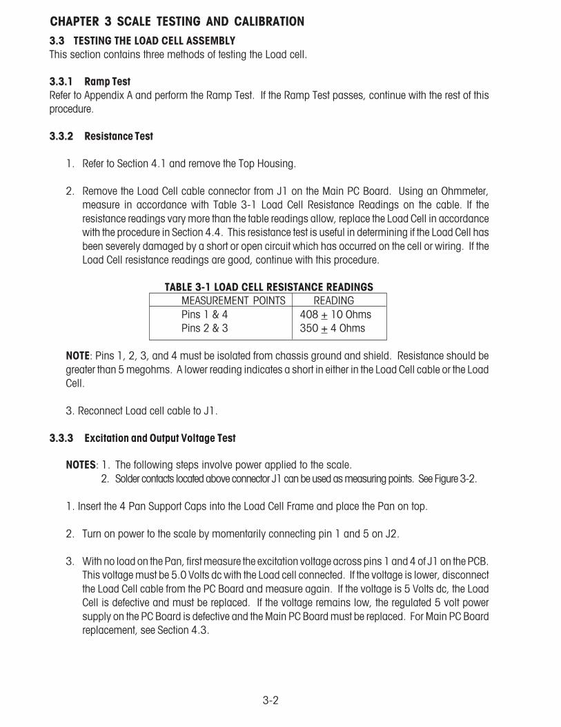
2. Remove the Load Cell cable connector from J1 on the Main PC Board. Using an Ohmmeter,measure in accordance with Table 3-1 Load Cell Resistance Readings on the cable. If theresistance readings vary more than the table readings allow, replace the Load Cell in accordancewith the procedure in Section 4.4. This resistance test is useful in determining if the Load Cell hasbeen severely damaged by a short or open circuit which has occurred on the cell or wiring. If theLoad Cell resistance readings are good, continue with this procedure.
TABLE 3-1 LOAD CELL RESISTANCE READINGSMEASUREMENT POINTS READINGPins 1 & 4 408 + 10 OhmsPins 2 & 3 350 + 4 Ohms
NOTE: Pins 1, 2, 3, and 4 must be isolated from chassis ground and shield. Resistance should begreater than 5 megohms. A lower reading indicates a short in either in the Load Cell cable or the LoadCell.
3. Reconnect Load cell cable to J1.
3.3.3 Excitation and Output Voltage Test
NOTES: 1. The following steps involve power applied to the scale. 2. Solder contacts located above connector J1 can be used as measuring points. See Figure 3-2.
1. Insert the 4 Pan Support Caps into the Load Cell Frame and place the Pan on top.
2. Turn on power to the scale by momentarily connecting pin 1 and 5 on J2.
3. With no load on the Pan, first measure the excitation voltage across pins 1 and 4 of J1 on the PCB.This voltage must be 5.0 Volts dc with the Load cell connected. If the voltage is lower, disconnectthe Load Cell cable from the PC Board and measure again. If the voltage is 5 Volts dc, the LoadCell is defective and must be replaced. If the voltage remains low, the regulated 5 volt powersupply on the PC Board is defective and the Main PC Board must be replaced. For Main PC Boardreplacement, see Section 4.3.

3-3
CHAPTER 3 SCALE TESTING AND CALIBRATION3.3.3 Excitation and Output Voltage Test (Cont.)
4. Measure the voltages on J1 across pins 2 and 3, +SIG and –SIG points. These measurementsrepresent the direct output of the Load Cell. Repeat measurements at 50% and full scalecapacities. See Table 3-2 for typical readings.
NOTE: Table 3-2 indicates typical readings, actual values can vary as much as 1.5 mV, but shouldremain linear throughout the entire range.
If readings are out of tolerance, replace the Load cell. See Section 4.4 for Load Cell replacement.
TABLE 3-2. LOAD CELL OUTPUT READINGS.NOMINAL OUTPUT IN MILLIVOLTS AT 5 VOLTS EXCITATION
CAPACITY NO LOAD 50% 100%3 kg 1.2 +1.5 no load + 2.2 no load + 4.46 kg 0.4 +1.5 no load + 2.0 no load + 4.015 kg 0.2 +1.5 no load + 2.5 no load + 5.0
Figure 3-2. FD Series Scales Interconnection Diagram.
B a tt. H o ld

3-4
CHAPTER 3 SCALE TESTING AND CALIBRATION
3.4 TESTING THE MAIN PC BOARDThe Main PC Board can be tested by measuring voltages and by using a simulator. The simulator replacesthe Load Cell during testing and is a useful tool for diagnosing problems.
3.4.1 Main PC Board Voltage MeasurementsPrior to making the voltage measurements, the battery should have been fully charged and tested.
1. Disconnect power from the scale.
2. Remove the Top housing, refer to Section 4.1 and leave the Membrane Switch connected to thescale.
3. Disconnect the battery from the Main PC Board.
4. Connect the AC Adapter to the scale.
5. Refer to Figure 3-2, Interconnection Diagram which illustrates the interconnections to the Main PCBoard and is shown as a top view.
6. Turn the scale on.
7. Using a DVM, measure the excitation voltage across pins 1 and 4 of JI that should be 5 volts dc.This is the excitation voltage for the Load Cell and is regulated. If the voltage is lower, replace theMain PC Board, refer to Section 4.3 and then perform Operational Tests in accordance with Section3.6.
8. Measure incoming power from the AC Adapter connector shown in Figure 3-2. The voltage shouldread between 9 and 14 volts dc with power off and above 9 Volts dc with power on.
9. With the battery disconnected from the main PC Board, measure voltage across pins 1 and 3 onthe battery connector on the PC Board. The voltage should read 1 to 3 Volts dc.
10.Connect the battery to the Main PC Board and measure the voltage across pins 1 and 3 on thebattery connector. The full battery voltage should read a minimum of 6.0 Volts dc. If the voltageis lower, the battery may require charging or it may be defective. Refer to section 3.5 and test thebattery.
11.Perform simulator testing.

3-5
CHAPTER 3 SCALE TESTING AND CALIBRATION3.4.2 Simulator TestingTo perform these tests, the use of a Simulator is required. The basic function of a Simulator is to simulatethe output of a full bridge Load Cell allowing the scale to be separated from the Load Cell for the purposesof troubleshooting and calibration. The Load Cell used in the scale is rated at 2mV/V output with a 5 Voltexcitation voltage applied.
General Load TestThis test checks the Main PC Board circuitry by simulating accurate load cell voltages at 0%, 50% and100% load capacities.
1. Disconnect power from the scale.
2. Remove the Top housing, refer to Section 4.1 and leave the Membrane Switch connected to thescale.
3. Disconnect the battery.
4. Disconnect the Load Cell cable from connector J1 on the main PC Board. Refer to Figure 3-2 forlocation.
5. With the Simulator set to zero, connect the Simulator to connector J1 using Alligator clips.
6. Connect a known good AC Adapter to the scale and connect to a power source.
7. Turn on the scale, CLEAR PAN, ERROR 14 should be displayed. This is normal.
8. Set the scale to indicate weight in kilograms (kg) and set the calibration value to maximum spanvalue.
9. Review Table 3-2 and adjust the Simulator to simulate 0% load, 50% load and 100% load for thecapacity that the scale is rated for. If the resulting readings are unstable, the Main PC Board isdefective. Use the Simulator to calibrate the scale in the next procedure to verify if the Main PC Boardis good or bad.
Calibration TestThis test calibrates the scale using the simulator and can verify that the Main PC Board is functioningproperly or improperly.
1. With the scale on and the Membrane Switch connected, enter the scale menu and perform a spancalibration according to the Instruction Manual.
2. Follow the scale prompts. When the scale indicates a given weight should be placed on the scale,set the simulator to an equivalent value based on Table 3-2. For example, when a span value of
6 kg for a 6 kg scale is shown, the simulator should be set to .8 mV/V.

3-6
CHAPTER 3 SCALE TESTING AND CALIBRATIONCalibration Test (Cont.)
3. Upon completion of calibration, the Main PC Board can be further checked using the Simulator tosimulate various weight values. If simulator settings and weight reading on the scale agree, theMain PC Board is functional. If the scale readings vary, or do not agree with readings in Table3-2, the Main PC Board is defective and should be replaced.
4. Remove power from the scale and proceed with Section 4.3 and replace the Main PC Board.
5. After Main PC Board replacement and assembly of the scale, perform Operational Tests in Section3.6.
3.5 TESTING THE BATTERYThe FD Series Scales contains a rechargable, 6.0 Volt, 4.5 Ampere rated, Lead-Acid Battery.
3.5.1 Precautions for Battery Handling
WARNING DEATH OR SERIOUS INJURY CAN OCCUR• Charge the battery only with the charger in the scale. Charging the battery under any
other conditions may cause the battery to overheat, emit hydrogen gas, Leak, igniteor burst.
• Operate the battery at normal temperature range as specified for the scale.• Do NOT short the battery terminals under any conditions.• Do NOT dispose of the battery in incinerators, or crush or try to open. Dispose of the
defective battery in accordance with local regulations for lead-acid type batteries.
CAUTION• Check the battery for any sign of irregularities in appearance. If there is any damage
to the case such as cracks, deformation or leakage, replace the battery with a new one.• Do NOT charge the battery with the charger terminals reversed.
3.5.2 Battery TestsA new battery when installed in the FD Series Scales will provide many years of useful service. The lengthof service depends upon the type of use of the scale. If left connected to the AC Adapter all of the time, thebattery receives a small charge when the battery voltage is low, service life can be many years.
The FD Series Scales can be operated for up to 120 hours per charge. Battery life can be maximized byfrequent charging.
1. Upon receipt of the scale, plug in the AC Adapter to a power source and the scale. Allow the batteryto charge. If the battery required a charge, the battery indicator on the front of the LCD display willindicate charging.
2. Refer to Section 4.1 and remove the Top Housing. Leave the Membrane Switch on the coverconnected to the scale.

3-7
CHAPTER 3 SCALE TESTING AND CALIBRATION3.5.2 Battery Tests (cont.)
3. With the AC Adapter connected, measure the battery voltage at the battery terminals; the voltageshould be approximately 6 to 7 Volts dc when charging. The voltage should be approximately6.4 Volts dc ten minutes after charging stops. The scale will operate until the battery voltage dropsto approximately 5.6 Volts dc.
NOTE: If the scale operates less than 120 hours, charge the battery and turn on the scale and testhow long the scale operates. If the scale operates less than 60 hours with no backlight, the batteryshould be replaced. This is 50% capacity.
4. Table 3-3 indicates the capacity of the battery in percentage after a full charge. Allow a chargedbattery to stand overnight without being charged and measure the terminal voltage to see capacityof the battery.
TABLE 3-3 BATTERY CAPACITY.
5. If the battery requires replacement, refer to Section 4.6, charge the new battery overnight andcheck scale performance.
3-8
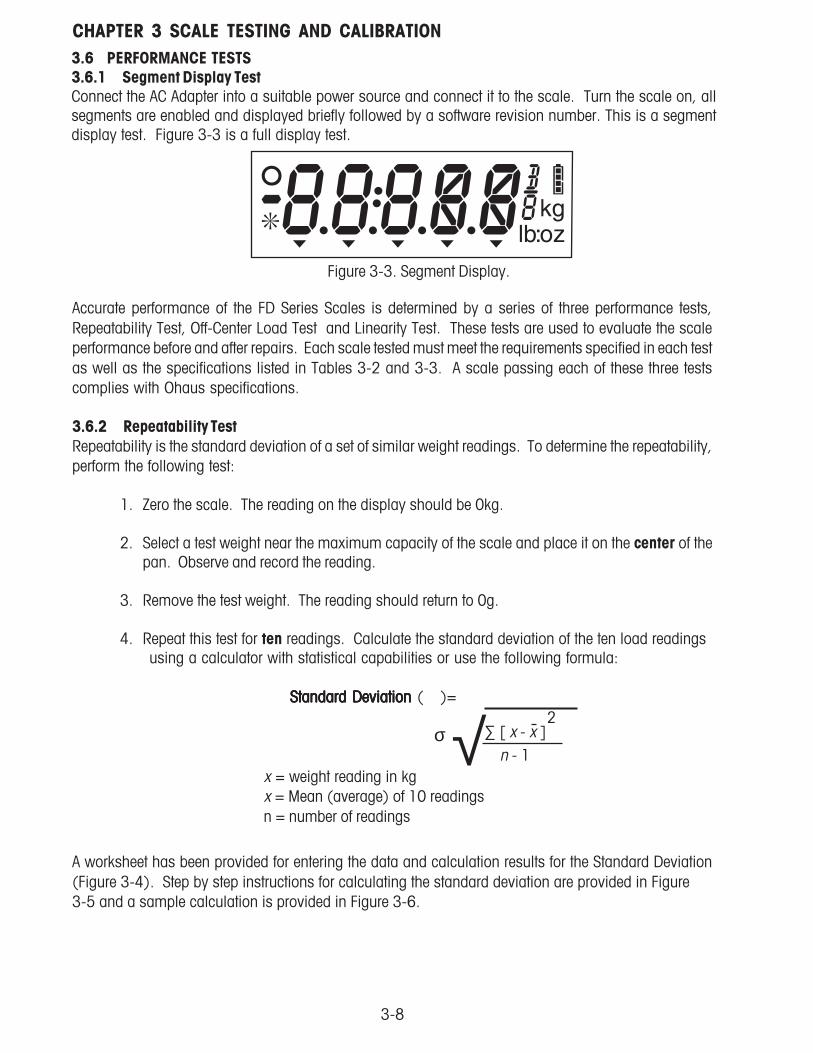
CHAPTER 3 SCALE TESTING AND CALIBRATION3.6 PERFORMANCE TESTS3.6.1 Segment Display TestConnect the AC Adapter into a suitable power source and connect it to the scale. Turn the scale on, allsegments are enabled and displayed briefly followed by a software revision number. This is a segmentdisplay test. Figure 3-3 is a full display test.
√∑ [ x - x ]2
n - 1 σ
Figure 3-3. Segment Display.
Accurate performance of the FD Series Scales is determined by a series of three performance tests,Repeatability Test, Off-Center Load Test and Linearity Test. These tests are used to evaluate the scaleperformance before and after repairs. Each scale tested must meet the requirements specified in each testas well as the specifications listed in Tables 3-2 and 3-3. A scale passing each of these three testscomplies with Ohaus specifications.
3.6.2 Repeatability TestRepeatability is the standard deviation of a set of similar weight readings. To determine the repeatability,perform the following test:
1. Zero the scale. The reading on the display should be 0kg.
2. Select a test weight near the maximum capacity of the scale and place it on the center of thepan. Observe and record the reading.
3. Remove the test weight. The reading should return to 0g.
4. Repeat this test for ten readings. Calculate the standard deviation of the ten load readingsusing a calculator with statistical capabilities or use the following formula:
Standard Deviation Standard Deviation Standard Deviation Standard Deviation Standard Deviation ( )=
x = weight reading in kgx = Mean (average) of 10 readingsn = number of readings
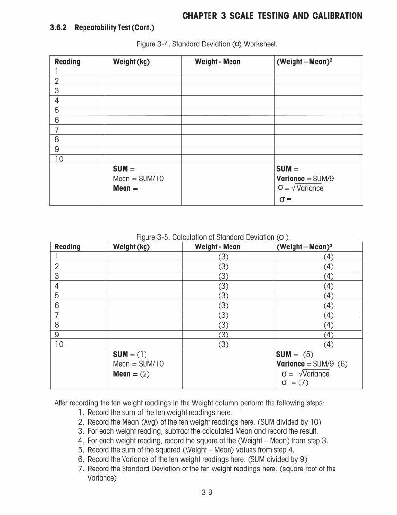
A worksheet has been provided for entering the data and calculation results for the Standard Deviation(Figure 3-4). Step by step instructions for calculating the standard deviation are provided in Figure3-5 and a sample calculation is provided in Figure 3-6.
3-9
CHAPTER 3 SCALE TESTING AND CALIBRATION
Reading Weight (kg) Weight - Mean (Weight – Mean)2
12345678910
SUM = SUM =Mean = SUM/10 Variance = SUM/9Mean ===== = Variance
= = = = =
Figure 3-5. Calculation of Standard Deviation ( ).Reading Weight (kg) Weight - Mean (Weight – Mean)2
1 (3) (4)2 (3) (4)3 (3) (4)4 (3) (4)5 (3) (4)6 (3) (4)7 (3) (4)8 (3) (4)9 (3) (4)10 (3) (4)
SUM = (1) SUM = (5)Mean = SUM/10 Variance = SUM/9 (6)Mean ===== (2) = Variance
After recording the ten weight readings in the Weight column perform the following steps:1. Record the sum of the ten weight readings here.2. Record the Mean (Avg) of the ten weight readings here. (SUM divided by 10)3. For each weight reading, subtract the calculated Mean and record the result.4. For each weight reading, record the square of the (Weight – Mean) from step 3.5. Record the sum of the squared (Weight – Mean) values from step 4.6. Record the Variance of the ten weight readings here. (SUM divided by 9)7. Record the Standard Deviation of the ten weight readings here. (square root of the
Variance)
σ
σ
σ
σ
σσ
√= (7)
3.6.2 Repeatability Test (Cont.)
Figure 3-4. Standard Deviation ( ) Worksheet.
√

3-10
CHAPTER 3 SCALE TESTING AND CALIBRATION
Figure 3-6. Sample Calculation of Standard Deviation ( ) for FD3 Scale.Reading Weight (kg) Weight - Mean (Weight – Mean)2
1 3000.5 0.4 0.162 3000.0 -0.1 0.013 3000.5 0.4 0.164 3000.0 -0.1 0.015 3000.5 0.4 0.166 3000.0 -0.1 0.017 2999.5 -0.6 0.368 3000.0 -0.1 0.019 3000.0 -0.1 0.0110 3000.0 -0.1 0.01
SUM = 30,001 SUM =0.9Mean = SUM/10 Variance SUM/9= 0.1Mean ===== 3,000.1 = Variance
===== 0.316228
Figure 3-7. Off-Center Load Test Weight Locations.
σ
σσ
√
3.6.3 Off-Center Load TestThe Off-Center Load Test is used to determine whether displayed weight values will be affected by movingthe load to different areas of the weighing Pan. See Figure 3-7.
3.6.2 Repeatability Test (Cont.)
NOTE: The above table represents a passing test. The results must be less than or equal to the Repeatabilityshown in table 3-4.

3-11
CHAPTER 3 SCALE TESTING AND CALIBRATION
1. Zero the scale.
2. Place a test weight equal to 1/2 the scale capacity in the center of the weighing Pan andrecord the reading.
3. Move the test weight to the mid-point between the center and the left edge of the weighingPan and record the reading.
4. Move the test weight to the mid-point between the center and the rear of the weighing Panand record the reading.
5. Move the test weight to the mid-point between the center and the right edge of the weighingPan and record the reading.
6. Move the test weight to the mid-point between the center and the front of the weighingPan and record the reading.
7. Subtract the center position reading from the reading at each outer position. The differenceat each test position should be within the off center load tolerance specified in Table 3-4.
3.6.4 Linearity TestThe Linearity test is used to determine the linearity of the scale throughout its operating range.
NOTE::::: The scale must pass the Repeatability and Off-Center Load Tests before the Linearity test isperformed. Before performing this test, calibrate the scale according to Appendix A.
1. Place masses totaling 1/3 of the capacity of the scale on the Pan and note the weight. Setthis mass aside, it will become the test mass.
2. Place masses totaling 1/3 of the capacity of the balance on the Pan and zero the scale.
3. Place the test mass on the Pan and record the weight.
4. Place masses totaling 2/3 of the capacity of the scale on the Pan and zero the scale.
5. Place the test mass on the Pan and record the weight.
6. The difference of the 3 recorded weights should be less than or equal to the tolerance valueslisted in Table 3-4.
3.6.3 Off-Center Load Test (Cont.)

3-12
CHAPTER 3 SCALE TESTING AND CALIBRATION
3.7 SPECIFICATIONSTABLE 3-4. SPECIFICATIONS.
NOTE: Product specifications are subject to change without any obligation on the manufacturer.
Maximum displayed resolution 1:6000 1:7500 1:7500
Model FD3 FD6 FD15Capacity x Readability(Max x d non-approved)
3 kg x 0.0005 kg3000 g x 0.5 g6 lb x 0.001 lb96 oz x 0.02 oz96 oz x 1/4 oz6 lb 0 oz x 0.1 oz6 lb 0 oz x 1/4 oz
6 kg x 0.001 kg6000 g x 1 g15 lb x 0.002 lb240 oz x 0.05 oz240 oz x 1/4 oz15 lb 0 oz x 0.1 oz15 lb 0 oz x 1/4oz
15 kg x 0.002 kg15000 g x 2 g30 lb x 0.005 lb480 oz x 0.1 oz480 oz x 1/4 oz30 lb 0 oz x 0.1 oz30 lb 0 oz x 1/4 oz
Capacity x Readability(Max x e approved)
3 kg x 0.001 kg3000 g x 1 g6 lb x 0.002 lb96 oz x 0.05 oz96 oz x 1/4 oz
6 kg x 0.002 kg6000 g x 2 g15 lb x 0.005 lb240 oz x 0.1 oz240 oz x 1/4 oz
15 kg x 0.005 kg15000 g x 5 g30 lb x 0.01 lb480 oz x 0.2 oz480 oz x 1/4 oz
Approved resolution
Linearity
1:3000 1:3000 1:3000
0.001 kg 0.002 kg 0.005 kg±0.001 kg ±0.002 kg ±0.005 kg
Power 9 VDC 0.5A AC AdapterInternal rechargeable sealed lead-acid battery
Checkweigh indicationApplication modes
Weight display 5-digit 19 mm high digits, 7-segment back lit LCD display(with fractional ounce and battery status indicator)
Weighing, Checkweighing
3 LEDs (yellow, green, red) with configurable alert beeper
Weighing units g, kg, lb, oz (decimal/fractional), lb:oz (decimal/fractional oz)
Keyboard
Typical battery life 120 hours with 15 hour recharge time
Tare range To capacity by subtraction
Stabilization time Within 2 seconds
Auto zero trackingOperating temperature range
Off, 0.5, 1 or 3 divisions-10 °C to 40 °C / 14 °F to 104 °F
Storage temperature rangeApproved temperature range
-40 °C to 70 °C / -40 °F to 158 °F0 °C to 40 °C / 32 °F to 104 °F
ProtectionConstruction
IP43304 Stainless steel housing and platform
Scale weightShipping weight
3.6 kg / 8.0 lb 5 kg / 11 lb
Pan size (DxW)Scale dimensions (DxWxH)Shipping dimensions (DxWxH)
209 x 209 mm / 8.2 x 8.2 in.300 x 223 x 71 mm / 9 x 12 x 2.8 in.
400 x 320 x 185 mm / 15.8 x 12.6 x 7.3 in.
Repeatability
4 - button membrane switch
Off-Center Load 0.001 kg 0.002 kg 0.005 kg

3-13
CHAPTER 3 SCALE TESTING AND CALIBRATION3.8 CALIBRATION
NNNNNOTE: Before calibrating the scale, make sure it is not set for Legal For Trade operation.
Calibration Types – The FD Series’ calibration can be adjusted in two ways, Span and Linearity. Spancalibration uses two calibration points to adjust the sensitivity of the scale. Linearity calibration uses threecalibration points to correct for non-linear weighing results.
Calibration Weights – Before beginning calibration, make sure that the required calibration weights areavailable. The model-specific calibration points are listed in the table below.
3.8.1 Calibration Points
NOTES: 1. Default calibration points are shown in bold print. 2. Calibration Units kg or lb are selected in the Setup sub-menu. 3. ASTM Class 4 or OIML Class F2 weights are required for calibration.
3.8.2 Span Calibration
1. Enter the menu by holding down the Menu button until Menu is displayed. When the button isreleased, CAL is displayed.
2. Press Yes to enter the Span menu.
3. With SPAN displayed, press the Yes button to begin the Span calibration process.
4. Clear the pan if prompted to do so, then press the Yes button.....
5. The display will show “--C--”, followed by the span calibration weight value.
6. If desired, press the No button to change to an alternate span calibration weight value.
7. Place the indicated calibration weight on the scale and press the Yes button.
8. The display will show “--C--”, then “done” and then revert to weighing. Remove the calibrationweight.
NOTE: The calibration procedure can be canceled at any time by pressing the Exit button or turning thescale off.
Linearity Calibration PointsModel Calibration Unit Span Calibration Points
FD3
FD6
FD15
kglb
Kglb
1, 2 or 3 kg2, 5 or 6 lb
2, 5 or 6 kg5, 10 or 15 lb
5, 10 or 15 kg10, 20 or 30 lb
1 or 2 and 3 kg2 or 4 and 6 lb2 or 4 and 6 kg5 or 10 and 15 lb
5 or 10 and 15 kg10 or 20 and 30 lb
Kglb
TABLE 3-5. CALIBRATION POINTS.

3-14
CHAPTER 3 SCALE TESTING AND CALIBRATION
3.8.3 Linearity Calibration
1. Enter the menu by holding down the Menu button until Menu is displayed. When the button isreleased, CAL is displayed.
2. Press the No button to advance to the Linearity calibration menu.
3. When LIN is displayed, press the Yes button to begin the linearity calibration process.
4. Clear the pan if prompted to do so, then press the Yes button.
5. The display will show “--C--”, followed by the first calibration weight value.
6. If desired, press the No button to change to an alternate first calibration weight value.
7. Place the indicated calibration weight on the scale and press the Yes button.
8. The display will show “--C--”, followed by the second calibration weight value.
9. Place the indicated calibration weight on the scale and press the Yes button.
10.The display will show “--C--”, then “done” and then revert to weighing. Remove the calibrationweight.
NOTE: The calibration procedure can be canceled at any time by pressing the Exit button or turningthe scale off.
3.9 MENU3.9.1 Menu StructureThe FD Series menu structure consists of three levels: Main, Sub-menu, and Menu item. The Main menucontains the Sub-menus and each Sub-menu contains several Menu items. Each Menu item contains twoor more settings.
TABLE 3-6. MENU STRUCTURE.Main menu
Sub-menu
Menu item

4-1
CHAPTER 4 REPAIR PROCEDURES4. REPAIR PROCEDURESThis section describes how to change individual components of the FD Series Scales. When doing this,please refer to the exploded view drawings and parts lists in Section 5.
Important: After replacing components, an operational test of the scale must always be carried out, (seeSection 3.6).
4.1 REMOVING TOP HOUSINGTo gain access to the components in the scale, perform the following procedures.
1. Remove power from the scale by disconnecting the AC adapter. Make sure the scale is off.
2. Carefully lift and remove the Pan from the scale.
3. Unscrew and remove the four Pan Support Caps from the top of the scale.
4. Turn the scale over and remove the four screws, which hold the Top Housing. Refer to Figure4-1 Top Housing Retaining Screws Location.
Figure 4-1. Top Housing Retaining Screws Location.
CAUTIONUse care in the next step as the membrane switch wiring is attached to the Main PC board.
5. Place the scale in the upright position and carefully lift the Top Housing from the BaseHousing about 50.8 mm (2 inches) to 76.2 mm (3 inches) and tilt forward. Reach under the TopHousing from the front and carefully disconnect the flexible cable from connector J2 on the MainPC board.
6. Set the Top Housing aside.

4-2
CHAPTER 4 REPAIR PROCEDURES
4.2 REPLACING THE MEMBRANE SWITCHThe membrane switch is affixed to the Top Housing of the scale. To replace the Membrane Switch, the scalemust be disassembled to gain access to the switch connections.
1. Refer to Section 4.1 and remove Top Housing.
CAUTIONUse care in the next step as the Membrane Switch wiring is attached to the PC board.
2. Place the scale in the upright position and carefully lift the Top Housing from the Base Housingabout 50.8 mm (2 inches) to 76.2 mm (3 inches). Reach under the Top Housing from the frontand carefully disconnect the flexible cable from connector J2 on the Main PC board.
3. On the Top Housing, lift up the defective Membrane Switch (if necessary carefully prying it up witha knife) and gently peel it off the upper housing.
4. Carefully clean the Top Housing membrane switch area (removing all traces of adhesive).The best method is to use a flat razor blade.
5. Insert the cable from the new Membrane Switch through the hole in the Top Housing. Peeloff the protective film from the new Membrane Switch and carefully align and affix to the upperhousing.
6. Press the Membrane Switch down uniformly. Using your fingers with a cloth, roll from thecenter of the Membrane Switch outward towards the edges to remove any air bubbles that maybe trapped.
CAUTIONDO NOT PRESS ON THE CLEAR WINDOW AREA OR ON THE SWITCHES.
7. Position the Top Housing in place over the base Housing and connect the flexible cable from theMembrane Switch to connector J2 on the Main PC board.
8. Reassemble the scale by replacing the four screws at the bottom of the scale which securethe upper housing.
9. Replace the Pan Support Caps and Pan on top of the scale.

4-3
CHAPTER 4 REPAIR PROCEDURES4.3 MAIN PC BOARD / LCD REPLACEMENTThe Main PC Board is located inside the scale towards the front. To replace the Main PC Board, it isnecessary to disassemble the scale. The LCD may also be replaced as a separate item if cracked or partialdisplays are shown.
4.3.1 Main PC Board Replacement
1. Refer to Section 4.1 and remove Top Housing.
2. Remove the BAT connector plug from the Main PC Board which is battery and the PWRconnector which is used for external power that connects to the AC Adapter plug on the BaseHousing. See Figure 4-2.
Figure 4-2. Connector Locations.
3. Remove connector from J1, which is used to connect the Load Cell.
4. Remove the four corner screws on the Main PC Board
5. Replace the Main PC Board and install the four screws previously removed.
6. Replace connector J1.
7. Replace the BAT and PWR connectors on the Main PC Board.
8. Position the Top Housing in place over the scale and connect the flexible cable from themembrane switch to connector J2 on the Main PC Board.
9. Check the LFT lock switch (legal for trade) switch. Make sure it is in the OFF position.
10. Turn on the scale. When self-testing is completed, the display may indicate an error code. This is normal.

4-4
CHAPTER 4 REPAIR PROCEDURES4.3.1 Main PC Board Replacement (Cont.)
11. Set the capacity, see Appendix A.3.
12. Calibrate the scale according to the Instructions in Appendix A
13. Turn the scale off then on. It will go through all the self-testing.
14. Reassemble the scale.
15. Replace the Pan Support Caps and Pan on top of the scale.
16.After repair, perform operational test, see Section 3.6. If possible, set the original customersettings back into the scale.
4.3.2 LCD ReplacementThis procedure is done when the LCD shows signs of visible damage such as cracked glass or partialdisplays and the scale operates normally in all other functions. The Main PC Board has to be removedfor this procedure.
NOTE: This procedure is very difficult and should not be attempted unless you have the proper tools.
1. Perform steps 1 through 4 of Section 4.3.1.
2. Carefully unsolder all contacts of the LCD and remove the LCD.
3. Replace the LCD and solder all connections, check the Main PC Board and make sure that solderhas not spilled over to other connections.
4. Continue with steps 5 through 16 of Section 4.3.1.

4-5
CHAPTER 4 REPAIR PROCEDURES
Figure 4-3. Load Cell Retaining Screws.
4.4 REPLACING THE LOAD CELL ASSEMBLY (WITH FRAME)The Load Cell Assembly is centrally located inside the scale. The Load Cell is factory assembled and theoverload protection stops are pre-adjusted. There are no adjustments to be made on this assembly afterinstallation.
1. Refer to Section 4.1 and remove Top Housing.
2. Remove connector from J1 on the Main PC Board.
3. Remove the four screws holding the Load Cell Assembly to the bottom housing. See Figure 4-3for screw locations.
4. Lift the Load Cell Assembly out of the bottom housing and replace with a new one. Install screws.
5. Connect connector J1 to the Main PC Board.
6. Position the upper housing in place over the scale and connect the flexible cable from themembrane switch to connector J2 on the Main PC board.
7. Check the LFT lock switch. Make sure it is in the OFF position.
8. Turn on the scale. When self-testing is completed, the display may indicate an error code. Thisis normal.
9. Calibrate the scale according to the instructions in Appendix A.
10.Turn the scale off then on. It will go through all the self-testing.
11. After repair, perform operational test, see Section 3.6. If possible, set the original customer settingsback into the scale.

4-6
CHAPTER 4 REPAIR PROCEDURES4.5 REPLACING THE LOAD CELL COMPONENTThis procedure is used when it is desired to keep the existing Load Cell Frame and just replace the Load cell.The Load Cell Assembly is centrally located inside the scale. When the new Load Cell is mounted to theexisting Frame, the Overload Protection Stops must be adjusted.
1. Refer to Section 4.1 and remove Top Housing.
2. Remove connector from J1 on the Main PC Board.
3. Remove the four screws holding the Load Cell Assembly to the Base Housing. See Figure 4-3 forscrew locations.
4. Lift the Load Cell Assembly out of the bottom housing.
5. On top of the Load Cell Frame, remove the 2 screws holding the Load cell.
6. On the bottom of the Load Cell Frame, remove the 2 screws holding the Load Cell.
7. Remove the cable clamp holding the Load Cell cable on the bottom of the Frame assembly.
8. Install the new Load Cell using the 4 screws previously removed. Torque the screws as indicatedin Table 4-1. Make sure the Load cell is properly aligned.
TABLE 4-1. LOAD CELL SCREW TORQUE INFORMATION. CAPACITY TORQUE
3 kg 7 N.m / 62 in. lb 6 kg 10 N.m / 88 in. lb15 kg 10 N.m / 88 in. lb
9. Re-Install the cable clamp holding the Load Cell cable on the bottom of the Frame assembly
10.Re-install the four screws holding the Load Cell Assembly to the Base Housing. See Figure 4-3 forscrew locations.
11. Install connector to J1 on the Main PC Board.
4.5.1 Overload Protection Stop AdjustmentWhen a Load Cell has been replaced in the existing Load Cell frame, the Overload Protection Stops mustbe set first before calibrating or testing the scale. This will require the use of mm feeler gauges ranging from0.35 mm to 2.1 mm or inch feeler gauges 0.013 in. to 0.082 in. See Table 4-2.
1. At each Overload Stop Protection location, insert the proper feeler gauge as specified in Table 4-2.
2. With the correct feeler gauge positioned in the first Overload Protection Stop, press down on theFrame and see if there is movement of the frame. Adjust the Overload Protection Stop until there isno movement with the feeler gauge inserted. The resulting gap should be the thickness of the feelergauge.

4-7
CHAPTER 4 REPAIR PROCEDURES
3. Repeat this procedure for all of the Overload Protection Stops using the appropriate feeler gauges.
4. When the initial gap setting have been made, recheck all gap settings and adjust as required.
5. Using a thread locking solution, coat all down stop screws so they will not move.
TABLE 4-2. LOAD CELL OVERLOAD PROTECTION STOP GAP SETTINGS CAPACITY LONG ARM MID SHORT ARM
3 kg 0.9 mm / 0.035 in. 0.35 mm / 0.013 in. 0.5 mm / 0.019 in.6 kg 1.0 mm / 0.039 in. 0.4 mm / 0.015 in. 0.75 mm / 0.029 in.
15 kg 2.1 mm / 0.082 in. 0.55 mm / 0.021 in. 1.0 mm / 0.039 in.
6. Reassemble the scale.
7. Calibrate the scale using Appendix A instructions. Check all operations,
4.6 REPLACING THE BATTERYThis procedure is used when it is required to change the Battery.
WARNING: DEATH OR SERIOUS INJURY CAN OCCUR• Charge the battery only with the charger in the scale. Charging the battery under anyother conditions may cause the battery to overheat, emit hydrogen gas, leak, igniteor burst.
• Operate the battery at normal temperature range as specified for the scale.• Do NOT short the battery terminals under any conditions.• Do NOT dispose of the battery in incinerators, or crush or try to open. Dispose of thedefective battery in accordance with local regulations for lead-acid type batteries.
CAUTION• Check the battery for any sign of irregularities in appearance. If there is any damage
to the case such as cracks, deformation or leakage, replace the battery with a new one.• Do NOT charge the battery with the charger terminals reversed.
1. Refer to Section 4.1 and remove Top Housing.
2. Disconnect the wire Harness from the battery.
3. Remove the two screws holding the Battery Holder on top of the Battery. These screws are reachedfrom underneath the scale on the Base Housing.
4. Lift the Battery out of the Base Housing.
5. Position the new Battery in place in the Base Housing.
6. Reinstall the Battery holder using the two screws.
4.5.1 Overload Protection Stop Adjustment (Cont.)

4-8
CHAPTER 4 REPAIR PROCEDURES
6. Place the Battery Holder in place over the Battery and secure with the two screws previouslyremoved.
7. Attach the two battery wires with clips to the Battery. Make sure the Red wire is attached to thepositive terminal on the Battery and the Black wire is attached to the negative terminal on theBattery.
CAUTION: Dispose of the Battery according to local regulations for hazardous materials. Donot incinerate, crush or throw out in regular garbage containers. Battery contains an acidsolution.
4.6 REPLACING THE BATTERY (Cont.)

5-1
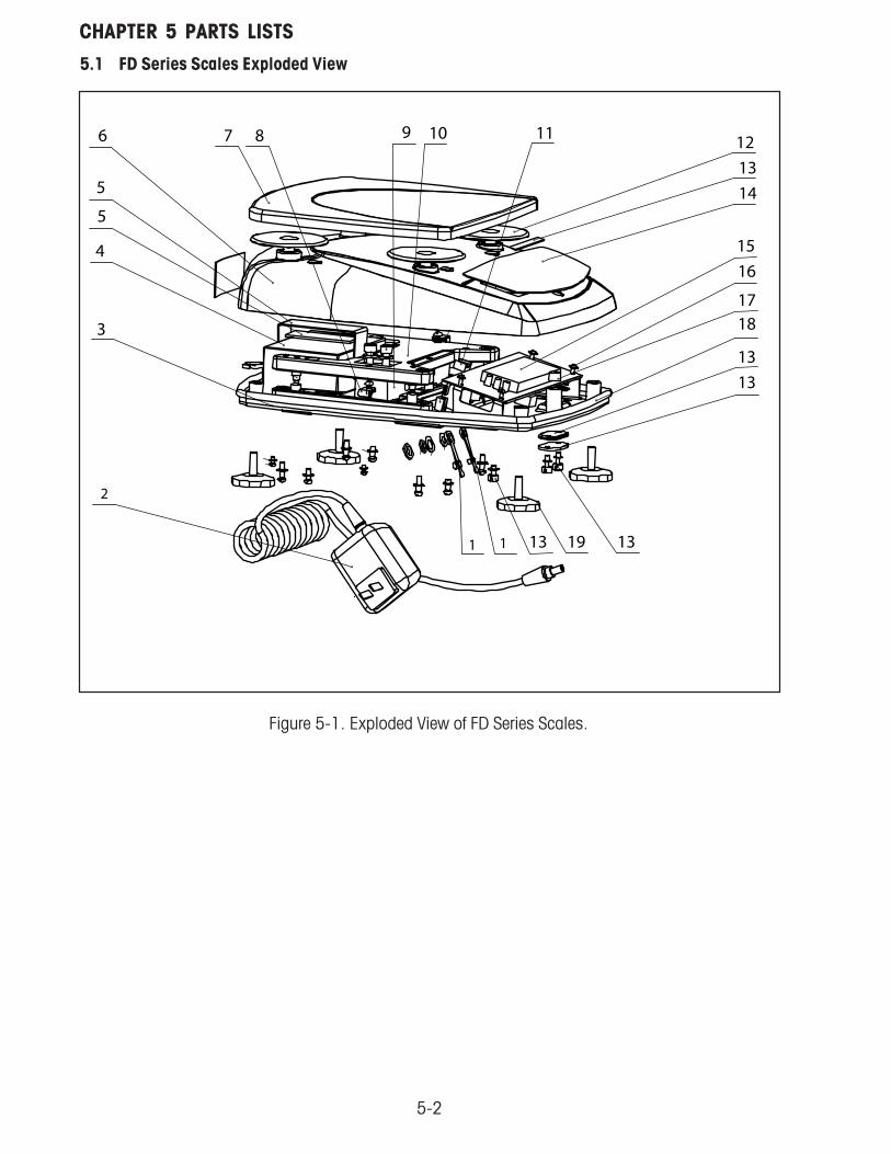
CHAPTER 5 PARTS LISTS5. PARTS LISTSThis section of the manual contains exploded views, and parts lists for the FD Series Scales. Theexploded view drawings identifies the replaceable parts.
NOTE:In all cases where a part is replaced, the scale must bethoroughly checked after the replacement is made.The scale MUST meet the parameters of all applicablespecifications in this manual.
If further technical information is needed, in the United States call toll-free 1-800-526-0659 between8.00 a.m. and 4.00 p.m. EST. An Ohaus factory service technician will be available to provideassistance. Outside the U.S.A., please visit our site www.Ohaus.com to locate the nearest Ohausoffice.
5-2
CHAPTER 5 PARTS LISTS
Figure 5-1. Exploded View of FD Series Scales.
5.1 FD Series Scales Exploded View

5-3
CHAPTER 5 PARTS LISTS
TABLE 5-1. FD SERIES SCALES PARTS LIST.
ITEM NO. PART NO. DESCRIPTION QUANTITY
1 71172937 Seal, Adapter & Foot Switch Socket, FD 1
2 80500435 AC Adapter, US 120 Volts, 60 Hz 1
2 80500521 AC Adapter, US 220 Volts, 60 Hz 1
2 80500437 AC Adapter, UK 230 Volts, 50 Hz 1
2 80500436 AC Adapter, EU 230 Volts, 50 Hz 1
2 80500462 AC Adapter, AU 240 Volts, 50 Hz 1
2 71143794 AC Adapter, JP 110 Volts, 50 Hz 1
3 71167489 Base Housing, FD 1
4 71168359 Rechargeable Battery Pack, FD 1
5 71172938 Battery Holder, FD 1
6 71172932 Top Housing 1
7 71167490 Pan, FD 1
8 71158353 Harness, Rechargeable Battery, FD 1
9 71119058 Load Cell, 3 kg, FD 1
9 71123142 Load Cell, 6 kg, FD 1
9 71123141 Load Cell, 15 kg, FD 1
10 71172916 Load Cell with Spiders (3 kg), FD 1
10 71172917 Load Cell with Spiders (6 kg), FD 1
10 71172918 Load Cell with Spiders (15 kg), FD 1
11 71172934 Harness, Adapter & Foot Switch, FD 1
12 71172940 Pan Support Caps, (4), FD 1
13 71172933 LFT Sealing Kit 1
14 71169710 Membrane Switch, FD 1
15 71158347 LCD Display, FD 1
16 71158350 Main PCB (with LCD), FD 1
17 71172935 Level Bubble, FD 1
18 71167481 Gasket, FD 1
19 71172939 Adjustable Feet (4), FD 1
Not Shown 71172941 Hardware Kit

5-4
CHAPTER 5 PARTS LISTS

A-1
APPENDIX A SERVICE MENU
A. INTRODUCTIONThis section describes the Service menu and sub-menus, which allow authorized service personnel toperform factory settings and calibration as well as setting the Geo code. There is also a ramp display usedto indicate the condition of the load cell. Please refer to the Service Menu diagram
CAP GEO CAL RAMP E.PAND END
AdjustCapacity
AdjustGeo
Factor
PerformCalibration
DisplayRampValue
Factoryuse only
Exits toWeigh Mode
no no no no no no
yes
yes
yes
yes
yes
yes yes yes
yes or no
Figure A-1. Service Menu Diagram.
A.1 ENTERING SERVICE MENU1. The following conditions must be met before entering the Service menu.
• The security switch must be in the OFF position.• LFT must be turned OFF in the Setup menu. (See note.)• The calibration Lock must be set to OFF in the Lock menu. (See note.).
NOTE: This requirement is waived when EEPROM checksum is erroneous.2. Turn the scale on.3. The Service menu is entered by pressing and holding the TARE and G/N/T buttons together for at
least 10 seconds, until SERVE is displayed briefly followed by CAP.
A.2 NAVIGATIONIn general, a blinking item on the display indicates a choice is available. Pressing Yes button accepts thedisplayed choice, pressing No button advances to the next choice or to the next menu. Pressing Exit buttonexits the service menu and returns to displaying the weight. Pressing Back button backs up 1 step in themenu.
A.3 CAPACITYThe capacity function allows the setting of either 3 kg, 6 kg or 15 kg full-scale capacity to match theinstalled Load Cell.
1. Press and hold the TARE and G/N/T buttons together for at least 10 seconds, SERVE is displayed.When the buttons are released, CAP is displayed for capacity.
2. To check the capacity of the scale, press the ON/ZERO Off button, 3 kg is displayed and is blinking.
3. To change the capacity of the scale to match the Load Cell, press the No button repeatedly untilthe correct capacity reading is displayed, then press the Yes button to accept. GEO is nowdisplayed.
Exits toweighing
yes

A-2
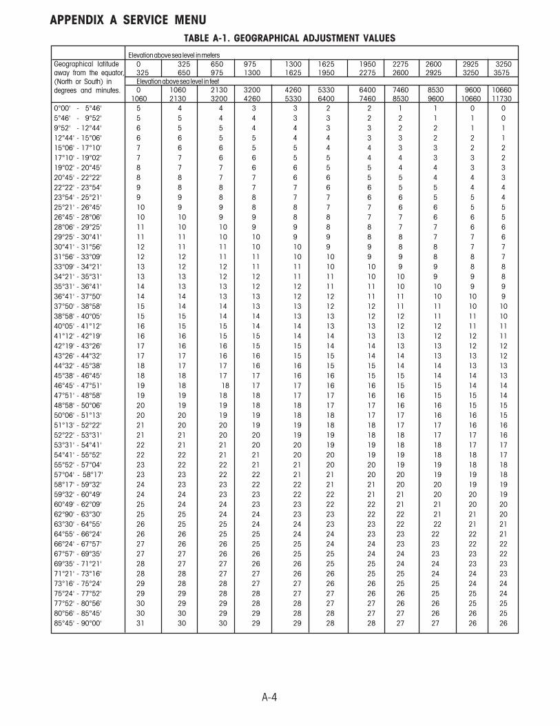
APPENDIX A SERVICE MENUA.4 GEOGRAPHICAL ADJUSTMENT FACTORThis menu item is used to allow entry of values from 0 to 31 and is used to compensate for slight variationsin gravity at different geographical locations around the world. (Complete Geographical Adjustment (Complete Geographical Adjustment (Complete Geographical Adjustment (Complete Geographical Adjustment (Complete Geographical AdjustmentFactors are listed in Table A-1.)Factors are listed in Table A-1.)Factors are listed in Table A-1.)Factors are listed in Table A-1.)Factors are listed in Table A-1.) The default Geo factor is 19 for Europe and 16 for USA. This featureallows authorized personnel to accurately calibrate the scale at a location other than the location wherethe scale is to be used. Prior to calibration, the Geo factor is set to correspond to the geographical locationwhere the calibration is being performed. Following calibration, the Geo factor is changed to match thelocation where the scale is used. If required, the scale may also be sealed according to the requiredapproval regulations.
1. With GEO displayed, press the Yes button, the current Geographical location is displayed andblinking, for example, GEO 19.
2. Locate the Geographical Factor in Table A-1. A number from 0 to 31 is selected.
3. To change the Geographical factor, press the No button until the desired GEO Factor is displayed,then, press the Yes button. CAL is now displayed.
A.5 SERVICE CALIBRATIONService calibration is used when span or linearity calibration fails or whenever a Load Cell or PC Board hasbeen changed. Using this procedure establishes a new set of parameters for the scale and new calibrationdata.
1. With CAL displayed, press the Yes button, CLEAR PAN is displayed and blinking.
2. Remove any material from the Pan and press the Yes button. - - C- - is now displayed.
3. After a few seconds, PLACE (n) kg (blinking), where (n) is the first calibration weight.
4. Place the requested weight on the Pan and press the Yes button. - - C- - is momentarily displayedfollowed by PLACE (n) kg where (n) is the second calibration weight.
5. Place the requested weights on the Pan and press the Yes button. - -C- - is momentarily displayedfollowed by DONE. Within a few seconds, the scale returns to a weighing mode and displays thecurrent weight on the Pan.
6. Remove the weights from the Pan.

A-3
APPENDIX A SERVICE MENU
A.6 RAMPRamp is used to primarily determine if the Load Cell is damaged from causes including abuse, heavyweights dropped on the Pan, or dropping the scale. The ramp function displays the duty cycle of theA/D converter output to within one tenth of a percent.
When in the ramp menu, placing a small weight on the Pan will cause the reading to increment slightly.Placing additional weights of the same value will also increment to a greater displayed value. This isnormal operation. A Load Cell that is damaged will be non-linear as additional weights are added andmight also have rapidly changing numbers. In this case, the Load Cell must be replaced.
1. When RAMP is displayed, press the Yes button to display the scales ramp values.
2. With an empty Pan, record the no load ramp value.
3. Place half load on the pan and record the ramp value.
4. Place a full load on the Pan and record the ramp value.
5. Subtract the no load ramp value from the half load ramp value.
6. Subtract the half load ramp value from the full load ramp value. The two calculated values shouldbe equal. The ramp value should be between 20% to 60% throughout testing. Values outsideof this range indicate the load cell should be replaced.
7. At the end of the testing, press the Yes button, E.PAND is displayed, disregard this display asit is not used.
8. Press the No button, END is displayed.
9. Press the Yes button to exit and return to the weighing mode.
A-4
APPENDIX A SERVICE MENU
Elevation above sea level in meters0 325 650 975 1300 1625 1950 2275 2600 2925 3250325 650 975 1300 1625 1950 2275 2600 2925 3250 3575Elevation above sea level in feet0 1060 2130 3200 4260 5330 6400 7460 8530 9600 10660
1060 2130 3200 4260 5330 6400 7460 8530 9600 10660 117300°00' - 5°46' 5 4 4 3 3 2 2 1 1 0 05°46' - 9°52' 5 5 4 4 3 3 2 2 1 1 09°52' - 12°44' 6 5 5 4 4 3 3 2 2 1 112°44' - 15°06' 6 6 5 5 4 4 3 3 2 2 115°06' - 17°10' 7 6 6 5 5 4 4 3 3 2 217°10' - 19°02' 7 7 6 6 5 5 4 4 3 3 219°02' - 20°45' 8 7 7 6 6 5 5 4 4 3 320°45' - 22°22' 8 8 7 7 6 6 5 5 4 4 322°22' - 23°54' 9 8 8 7 7 6 6 5 5 4 423°54' - 25°21' 9 9 8 8 7 7 6 6 5 5 425°21' - 26°45' 10 9 9 8 8 7 7 6 6 5 526°45' - 28°06' 10 10 9 9 8 8 7 7 6 6 528°06' - 29°25' 11 10 10 9 9 8 8 7 7 6 629°25' - 30°41' 11 11 10 10 9 9 8 8 7 7 630°41' - 31°56' 12 11 11 10 10 9 9 8 8 7 731°56' - 33°09' 12 12 11 11 10 10 9 9 8 8 733°09' - 34°21' 13 12 12 11 11 10 10 9 9 8 834°21' - 35°31' 13 13 12 12 11 11 10 10 9 9 835°31' - 36°41' 14 13 13 12 12 11 11 10 10 9 936°41' - 37°50' 14 14 13 13 12 12 11 11 10 10 937°50' - 38°58' 15 14 14 13 13 12 12 11 11 10 1038°58' - 40°05' 15 15 14 14 13 13 12 12 11 11 1040°05' - 41°12' 16 15 15 14 14 13 13 12 12 11 1141°12' - 42°19' 16 16 15 15 14 14 13 13 12 12 1142°19' - 43°26' 17 16 16 15 15 14 14 13 13 12 1243°26' - 44°32' 17 17 16 16 15 15 14 14 13 13 1244°32' - 45°38' 18 17 17 16 16 15 15 14 14 13 1345°38' - 46°45' 18 18 17 17 16 16 15 15 14 14 1346°45' - 47°51' 19 18 18 17 17 16 16 15 15 14 1447°51' - 48°58' 19 19 18 18 17 17 16 16 15 15 1448°58' - 50°06' 20 19 19 18 18 17 17 16 16 15 1550°06' - 51°13' 20 20 19 19 18 18 17 17 16 16 1551°13' - 52°22' 21 20 20 19 19 18 18 17 17 16 1652°22' - 53°31' 21 21 20 20 19 19 18 18 17 17 1653°31' - 54°41' 22 21 21 20 20 19 19 18 18 17 1754°41' - 55°52' 22 22 21 21 20 20 19 19 18 18 1755°52' - 57°04' 23 22 22 21 21 20 20 19 19 18 1857°04' - 58°17' 23 23 22 22 21 21 20 20 19 19 1858°17' - 59°32' 24 23 23 22 22 21 21 20 20 19 1959°32' - 60°49' 24 24 23 23 22 22 21 21 20 20 1960°49' - 62°09' 25 24 24 23 23 22 22 21 21 20 2062°90' - 63°30' 25 25 24 24 23 23 22 22 21 21 2063°30' - 64°55' 26 25 25 24 24 23 23 22 22 21 2164°55' - 66°24' 26 26 25 25 24 24 23 23 22 22 2166°24' - 67°57' 27 26 26 25 25 24 24 23 23 22 2267°57' - 69°35' 27 27 26 26 25 25 24 24 23 23 2269°35' - 71°21' 28 27 27 26 26 25 25 24 24 23 2371°21' - 73°16' 28 28 27 27 26 26 25 25 24 24 2373°16' - 75°24' 29 28 28 27 27 26 26 25 25 24 2475°24' - 77°52' 29 29 28 28 27 27 26 26 25 25 2477°52' - 80°56' 30 29 29 28 28 27 27 26 26 25 2580°56' - 85°45' 30 30 29 29 28 28 27 27 26 26 2585°45' - 90°00' 31 30 30 29 29 28 28 27 27 26 26
TABLE A-1. GEOGRAPHICAL ADJUSTMENT VALUES
Geographical latitudeaway from the equator,(North or South) indegrees and minutes.


PN 80250906 SERVICE MANUAL - FD SERIES SCALES
*80250906*
Test Equipment Depot - 800.517.8431 - 99 Washington Street Melrose, MA 02176 - TestEquipmentDepot.com