FCTM date 21-Aug-14
394
REFERENCE: LAO A318/A319/A320/A321 FLEET FCTM ISSUE DATE: 21 AUG 14 A318/A319/A320/A321 FLIGHT CREW TRAINING MANUAL The content of this document is the property of Airbus. It is supplied in confidence and commercial security on its contents must be maintained. It must not be used for any purpose other than that for which it is supplied, nor may information contained in it be disclosed to unauthorized persons. It must not be reproduced in whole or in part without permission in writing from the owners of the copyright. © AIRBUS 2005. All rights reserved.
Transcript of FCTM date 21-Aug-14

7/21/2019 FCTM date 21-Aug-14
http://slidepdf.com/reader/full/fctm-date-21-aug-14 1/393
REFERENCE: LAO A318/A319/A320/A321 FLEET FCTM ISSUE DATE: 21 AUG 14
A318/A319/A320/A321
FLIGHT CREW TRAINING MANUAL
The content of this document is the property of Airbus. It is supplied in confidence and commercial
security on its contents must be maintained. It must not be used for any purpose other than that forwhich it is supplied, nor may information contained in it be disclosed to unauthorized persons. It must
not be reproduced in whole or in part without permission in writing from the owners of the copyright. © AIRBUS 2005. All rights reserved.

7/21/2019 FCTM date 21-Aug-14
http://slidepdf.com/reader/full/fctm-date-21-aug-14 2/393
Intentionally left blank

7/21/2019 FCTM date 21-Aug-14
http://slidepdf.com/reader/full/fctm-date-21-aug-14 3/393
A318/A319/A320/A321FLIGHT CREW TRAINING MANUAL
TRANSMITTAL LETTER
LAO A318/A319/A320/A321 FLEET TRL P 1/2
FCTM 21 AUG 14
Issue date: 21 AUG 14
This is the FLIGHT CREW TRAINING MANUAL at issue date 21 AUG 14 for theA318/A319/A320/A321 and replacing last issue dated 06 MAR 14

7/21/2019 FCTM date 21-Aug-14
http://slidepdf.com/reader/full/fctm-date-21-aug-14 4/393
A318/A319/A320/A321FLIGHT CREW TRAINING MANUAL
TRANSMITTAL LETTER
Intentionally left blank
LAO A318/A319/A320/A321 FLEET TRL P 2/2
FCTM 21 AUG 14

7/21/2019 FCTM date 21-Aug-14
http://slidepdf.com/reader/full/fctm-date-21-aug-14 5/393
A318/A319/A320/A321FLIGHT CREW TRAINING MANUAL
FILING INSTRUCTIONS
LAO A318/A319/A320/A321 FLEET FI P 1/2
FCTM 21 AUG 14
Please incorporate this revision as follow:
InsertLocalization
Subsection TitleRemove
Rev. Date
PLP-LESSLIST OF EFFECTIVE SECTIONS/SUBSECTIONS
ALL 21 AUG 14
PLP-LOMLIST OF MODIFICATIONS
ALL 21 AUG 14
OP-PLP-TOCTABLE OF CONTENTS
ALL 21 AUG 14
OP-PLP-SOH
SUMMARY OF HIGHLIGHTSALL 21 AUG 14
OP-020Flight Controls
ALL 21 AUG 14
OP-040ECAM
ALL 21 AUG 14
NO-PLP-TOCTABLE OF CONTENTS
ALL 21 AUG 14
NO-PLP-SOHSUMMARY OF HIGHLIGHTS
ALL 21 AUG 14
NO-020Pre Start
ALL 21 AUG 14
NO-030START
ALL 21 AUG 14
NO-040Taxi
ALL 21 AUG 14
NO-050Takeoff
ALL 21 AUG 14
NO-080DESCENT PREPARATION
ALL 21 AUG 14
NO-090Descent
ALL 21 AUG 14
NO-110Approach General
ALL 21 AUG 14
NO-170Landing
ALL 21 AUG 14
NO-190Taxi In
ALL 21 AUG 14
AO-PLP-TOCTABLE OF CONTENTS
ALL 21 AUG 14
AO-PLP-SOHSUMMARY OF HIGHLIGHTS
ALL 21 AUG 14
Continued on the following page

7/21/2019 FCTM date 21-Aug-14
http://slidepdf.com/reader/full/fctm-date-21-aug-14 6/393
A318/A319/A320/A321FLIGHT CREW TRAINING MANUAL
FILING INSTRUCTIONS
LAO A318/A319/A320/A321 FLEET FI P 2/2
FCTM 21 AUG 14
Continued from the previous page
InsertLocalizationSubsection Title
RemoveRev. Date
AO-020OPERATING TECHNIQUES
ALL 21 AUG 14
AO-028FUEL
ALL 21 AUG 14
AO-029Hydraulic
ALL 21 AUG 14
SI-PLP-TOCTABLE OF CONTENTS
ALL 21 AUG 14
SI-PLP-SOHSUMMARY OF HIGHLIGHTS
ALL 21 AUG 14
SI-010Adverse Weather
ALL 21 AUG 14

7/21/2019 FCTM date 21-Aug-14
http://slidepdf.com/reader/full/fctm-date-21-aug-14 7/393
PRELIMINARY PAGES

7/21/2019 FCTM date 21-Aug-14
http://slidepdf.com/reader/full/fctm-date-21-aug-14 8/393
Intentionally left blank

7/21/2019 FCTM date 21-Aug-14
http://slidepdf.com/reader/full/fctm-date-21-aug-14 9/393
A318/A319/A320/A321FLIGHT CREW TRAINING MANUAL
PRELIMINARY PAGES
TABLE OF CONTENTS
LAO A318/A319/A320/A321 FLEET PLP-TOC P 1/2
FCTM 17 DEC 13
IN General Information
OP Operational Philosophy
NO Normal Operations
AO Abnormal Operations
SI Supplementary Information
PIR Preventing Identified Risks

7/21/2019 FCTM date 21-Aug-14
http://slidepdf.com/reader/full/fctm-date-21-aug-14 10/393
A318/A319/A320/A321FLIGHT CREW TRAINING MANUAL
PRELIMINARY PAGES
TABLE OF CONTENTS
Intentionally left blank
LAO A318/A319/A320/A321 FLEET PLP-TOC P 2/2
FCTM 17 DEC 13

7/21/2019 FCTM date 21-Aug-14
http://slidepdf.com/reader/full/fctm-date-21-aug-14 11/393
A318/A319/A320/A321FLIGHT CREW TRAINING MANUAL
PRELIMINARY PAGES
LIST OF EFFECTIVE SECTIONS/SUBSECTIONS
LAO A318/A319/A320/A321 FLEET PLP-LESS P 1/2
FCTM 21 AUG 14
M(1)
Localization Subsection Title Rev. Date
PLP-LETDU LIST OF EFFECTIVE TEMPORARY DOCUMENTARY UNITS 28 NOV 12
IN General Information 17 DEC 13
OP-010 INTRODUCTION 28 NOV 12
R OP-020 Flight Controls 21 AUG 14
OP-030 AP / FD / A/THR 06 MAR 14
R OP-040 ECAM 21 AUG 14
NO-010 GENERAL 27 AUG 13
R NO-020 Pre Start 21 AUG 14
R NO-030 START 21 AUG 14
R NO-040 Taxi 21 AUG 14
R NO-050 Takeoff 21 AUG 14
NO-060 CLIMB 24 AUG 11
NO-070 Cruise 06 MAR 14
R NO-080 DESCENT PREPARATION 21 AUG 14
R NO-090 Descent 21 AUG 14
NO-100 HOLDING 31 MAY 12
R NO-110 Approach General 21 AUG 14
NO-120 ILS Approach 06 MAR 14
NO-130 Non Precision Approach 06 MAR 14
NO-140 CIRCLING APPROACH 31 MAY 12
NO-150 VISUAL APPROACH 27 AUG 13
NO-160 PRECISION APPROACH 15 FEB 13
R NO-170 Landing 21 AUG 14
NO-180 Go Around 06 MAR 14
R NO-190 Taxi In 21 AUG 14
AO-010 GENERAL 31 MAY 12
R AO-020 OPERATING TECHNIQUES 21 AUG 14
AO-022 AUTOFLIGHT 28 NOV 11
AO-024 ELECTRICAL 24 AUG 11
AO-026 Fire Protection 17 DEC 13
AO-027 FLIGHT CONTROLS 31 MAY 12
R AO-028 FUEL 21 AUG 14
R AO-029 Hydraulic 21 AUG 14
AO-032 LANDING GEAR 15 FEB 13
AO-034 NAVIGATION 06 MAR 14
AO-070-A All Engine Flameout 06 MAR 14
AO-090 Miscellaneous 06 MAR 14
R SI-010 Adverse Weather 21 AUG 14
SI-020 Flying Reference 06 MAR 14
SI-030 Navigation Accuracy 06 MAR 14
Continued on the following page

7/21/2019 FCTM date 21-Aug-14
http://slidepdf.com/reader/full/fctm-date-21-aug-14 12/393
A318/A319/A320/A321FLIGHT CREW TRAINING MANUAL
PRELIMINARY PAGES
LIST OF EFFECTIVE SECTIONS/SUBSECTIONS
LAO A318/A319/A320/A321 FLEET PLP-LESS P 2/2
FCTM 21 AUG 14
Continued from the previous page
M(1) Localization Subsection Title Rev. DateSI-040 ZFW - ZFCG Entry Errors 06 MAR 14
SI-060 TCAS 06 MAR 14
SI-070 Use of Radar 06 MAR 14
SI-090 Landing Performance 06 MAR 14
SI-100 Green Operating Procedures 17 DEC 13
PIR-010 PREVENTING IDENTIFIED RISKS 06 MAR 14
(1) Evolution code : N=New, R=Revised, E=Effectivity, M=Moved

7/21/2019 FCTM date 21-Aug-14
http://slidepdf.com/reader/full/fctm-date-21-aug-14 13/393
A318/A319/A320/A321FLIGHT CREW TRAINING MANUAL
PRELIMINARY PAGES
LIST OF EFFECTIVE TEMPORARY DOCUMENTARY UNITS
LAO A318/A319/A320/A321 FLEET PLP-LETDU P 1/2
FCTM 28 NOV 12
M Localization DU Title DU identification DU date
No Temporary Documentary Unit

7/21/2019 FCTM date 21-Aug-14
http://slidepdf.com/reader/full/fctm-date-21-aug-14 14/393
A318/A319/A320/A321FLIGHT CREW TRAINING MANUAL
PRELIMINARY PAGES
LIST OF EFFECTIVE TEMPORARY DOCUMENTARY UNITS
Intentionally left blank
LAO A318/A319/A320/A321 FLEET PLP-LETDU P 2/2
FCTM 28 NOV 12

7/21/2019 FCTM date 21-Aug-14
http://slidepdf.com/reader/full/fctm-date-21-aug-14 15/393
A318/A319/A320/A321FLIGHT CREW TRAINING MANUAL
PRELIMINARY PAGES
AIRCRAFT ALLOCATION TABLE
LAO A318/A319/A320/A321 FLEET PLP-AAT P 1/2
FCTM 28 NOV 12
This table gives, for each delivered aircraft, the cross reference between:
- The Manufacturing Serial Number (MSN).- The Fleet Serial Number (FSN) of the aircraft as known by AIRBUS S.A.S.- The registration number of the aircraft as known by AIRBUS S.A.S.- The aircraft model.
M(1)
MSN FSN Registration Number Model
4596 RDPL34188 320-214
4639 RDPL34199 320-214
5356 PL34223 320-214
5396 PL34224 320-214
(1) Evolution code : N=New, R=Revised

7/21/2019 FCTM date 21-Aug-14
http://slidepdf.com/reader/full/fctm-date-21-aug-14 16/393
A318/A319/A320/A321FLIGHT CREW TRAINING MANUAL
PRELIMINARY PAGES
AIRCRAFT ALLOCATION TABLE
Intentionally left blank
LAO A318/A319/A320/A321 FLEET PLP-AAT P 2/2
FCTM 28 NOV 12

7/21/2019 FCTM date 21-Aug-14
http://slidepdf.com/reader/full/fctm-date-21-aug-14 17/393
A318/A319/A320/A321FLIGHT CREW TRAINING MANUAL
PRELIMINARY PAGES
LIST OF MODIFICATIONS
LAO A318/A319/A320/A321 FLEET PLP-LOM P 1/4
FCTM 21 AUG 14
M(1)
MODIFICATION Linked SB Incorp. Date Title
J0071 24 AUG 11 WINGS-WING TIP FENCES-INTRODUCE WING TIPSINCLUDING FENCES-
Applicable to: ALL
P10383 08 FEB 12 INDICATING/RECORDING SYSTEMS - FLIGHTWARNING COMPUTER (FWC) - INSTALL FWCSTANDARD H2-F5
Applicable to: ALL
P10694 24 AUG 11 AUTO-FLIGHT - FMGC - ACTIVATE "MOD NAV GOAROUND" ON FMGC
Applicable to: ALL
P12173 17 DEC 13 NAVIGATION-WEATHER RADAR SYSTEM-INSTALLCOLLINS MULTISCAN WXR IN FULL SINGLE CONFIGAND MULTISCAN FUNCTION ACTIVATED
Applicable to: MSN 5356-5396
P3379 24 AUG 11 INDICATING/RECORDING SYSTEMS - GENERAL- DEFINE CPIP3
Applicable to: ALL
P3511 24 AUG 11 AUTO FLIGHT - FAC - INSTALL TWO FACS P/N BAM0509
Applicable to: ALL
P3560 24 AUG 11 AUTO FLIGHT - FMGC - PROVIDE TIME CONSTRAINT
AND TEN CHARACTERS RTE IDENT FUNCTIONSApplicable to: ALL
P3686 24 AUG 11 AUTO FLIGHT-FAC-INTRODUCE FAC P/N BAM 510Applicable to: ALL
P3924 24 AUG 11 LANDING GEAR - MLG - MESSIER - INTRODUCEBRAKES P/N C202253
Applicable to: ALL
P4319 24 AUG 11 AUTO FLIGHT - FCU - DEFINE FLIGHT DIRECTORENGAGEMENT IN CROSSED BARS AT GO AROUND
Applicable to: ALL
P4320 24 AUG 11 AUTO FLIGHT-GENERAL-ACTIVATE GLOBAL SPEEDPROTECTION AND F/D DISENGAGEMENT UPONSPEED CONSTRAINTS
Applicable to: ALL
P4576 24 AUG 11 LANDING GEAR-ALTERNATE BRAKING- INTRODUCEMODIFIED ALTERNATE BRAKING SYSTEM
Applicable to: ALL
P4808 24 AUG 11 LANDING GEAR-WHEELS AND BRAKES- INTRODUCEBSCU COMMON STD
Applicable to: ALL
Continued on the following page

7/21/2019 FCTM date 21-Aug-14
http://slidepdf.com/reader/full/fctm-date-21-aug-14 18/393
A318/A319/A320/A321FLIGHT CREW TRAINING MANUAL
PRELIMINARY PAGES
LIST OF MODIFICATIONS
LAO A318/A319/A320/A321 FLEET PLP-LOM P 2/4
FCTM 21 AUG 14
Continued from the previous page
M(1) MODIFICATION Linked SB Incorp. Date TitleP5168 24 AUG 11 NAVIGATION - MMR - INSTALL COLLINS MMR
PROVIDING ILS AND GPS FUNCTIONApplicable to: ALL
P5518 24 AUG 11 LANDING GEAR-NORMAL BRAKING- INTRODUCESTD 8 BSCU (TWIN VERSION)
Applicable to: ALL
P5768 24 AUG 11 ELEC PWR-AC EMERGENCY GENERATION- ACTIVATE A319/A321 ELECTRICAL EMERGENCYCONFIGURATION ON A320 A/C
Applicable to: ALLP6054 24 AUG 11 NAVIGATION - MMR - ACTIVATE GPS PRIMARY
FUNCTION (HYBRID) IN SEXTANT MMR (WITHHONEYWELL OR LITTON ADIRU)
Applicable to: MSN 4596-4639
P6183 24 AUG 11 NAVIGATION - MMR - REMOVE COLLINS MMRPROVIDING ILS (FM IMMUNE) AND GPS PRIMARYFUNCTION (PREVIOUS SPEC.)
Applicable to: MSN 4596-4639
P6375 24 AUG 11 LANDING GEAR-PARKING/ULTIMATE EMERGENCYBRAKING-INTRODUCE A PRESSURE SWITCH
Applicable to: ALLP7373 24 AUG 11 AUTOFLIGHT - FMGC DEFINE AND INSTALL FMGC
CFM C13043AA01 THALES(EQUIPPED WITH FMS2THALES/SMITH)
Applicable to: MSN 4596-4639
P7519 24 AUG 11 AUTOFLIGHT-FMGC-INSTALL FMGC CFMC13042AA01 (EQUIPPED WITH FMS2) HONEYWELL
Applicable to: ALL
P7666 24 AUG 11 AUTO FLIGHT - FMGC DEVELOP FMS 2NDGENERATION THALES/SMITH REV 1 STANDARD
Applicable to: MSN 4596-4639
P7790 24 AUG 11 AUTO FLIGHT - FLIGHT MANAGEMENTAND GUIDANCE SYSTEM - ACTIVATE FMAENHANCEMENT FUNCTION
Applicable to: ALL
N P8076 21 AUG 14 LANDING GEAR - NORMAL BRAKING - INSTALLBSCU STD L4.5
Applicable to: ALL
N P8866 21 AUG 14 LANDING GEAR - NORMAL BRAKING - INSTALLBSCU STD L4.8 (EM2)
Applicable to: ALL
Continued on the following page

7/21/2019 FCTM date 21-Aug-14
http://slidepdf.com/reader/full/fctm-date-21-aug-14 19/393
A318/A319/A320/A321FLIGHT CREW TRAINING MANUAL
PRELIMINARY PAGES
LIST OF MODIFICATIONS
LAO A318/A319/A320/A321 FLEET PLP-LOM P 3/4
FCTM 21 AUG 14
Continued from the previous page
M(1) MODIFICATION Linked SB Incorp. Date TitleP9171 24 AUG 11 NAVIGATION-AIR DATA/INERTIAL REFERENCE
SYSTEM (ADIRS) - INTRODUCE AIR DATAMONITORING FUNCTION
Applicable to: ALL
N P9655 21 AUG 14 LANDING GEAR - NORMAL BRAKING - INSTALLBSCU SOFTWARE STD "L4.9"
Applicable to: ALL
(1) Evolution code : N=New, R=Revised, E=Effectivity

7/21/2019 FCTM date 21-Aug-14
http://slidepdf.com/reader/full/fctm-date-21-aug-14 20/393
A318/A319/A320/A321FLIGHT CREW TRAINING MANUAL
PRELIMINARY PAGES
LIST OF MODIFICATIONS
Intentionally left blank
LAO A318/A319/A320/A321 FLEET PLP-LOM P 4/4
FCTM 21 AUG 14

7/21/2019 FCTM date 21-Aug-14
http://slidepdf.com/reader/full/fctm-date-21-aug-14 21/393
GENERAL INFORMATION

7/21/2019 FCTM date 21-Aug-14
http://slidepdf.com/reader/full/fctm-date-21-aug-14 22/393
Intentionally left blank

7/21/2019 FCTM date 21-Aug-14
http://slidepdf.com/reader/full/fctm-date-21-aug-14 23/393
A318/A319/A320/A321FLIGHT CREW TRAINING MANUAL
GENERAL INFORMATION
PRELIMINARY PAGES
TABLE OF CONTENTS
LAO A318/A319/A320/A321 FLEET IN-PLP-TOC P 1/2
FCTM 17 DEC 13
FCTM Purpose.........................................................................................................................................................A

7/21/2019 FCTM date 21-Aug-14
http://slidepdf.com/reader/full/fctm-date-21-aug-14 24/393
A318/A319/A320/A321FLIGHT CREW TRAINING MANUAL
GENERAL INFORMATION
PRELIMINARY PAGES
TABLE OF CONTENTS
Intentionally left blank
LAO A318/A319/A320/A321 FLEET IN-PLP-TOC P 2/2
FCTM 17 DEC 13

7/21/2019 FCTM date 21-Aug-14
http://slidepdf.com/reader/full/fctm-date-21-aug-14 25/393
A318/A319/A320/A321FLIGHT CREW TRAINING MANUAL
GENERAL INFORMATION
LAO A318/A319/A320/A321 FLEET IN P 1/2
FCTM A 17 DEC 13
FCTM PURPOSE
Applicable to: ALL
Ident.: IN-010-00005422.0001001 / 12 MAR 08
The Flight Crew Training Manual (FCTM) is published as a supplement to the Flight Crew Operating
Manual (FCOM) and is designed to provide pilots with practical information on how to operate theAirbus aircraft. It should be read in conjunction with the FCOM. In the case of any conflict, the FCOM
is the over-riding authority.Airline training policy may differ in certain areas. Should this be the case, the airline training policy isthe over-riding authority.
Ident.: IN-010-00005423.0001001 / 18 NOV 13
COMMENT - QUESTIONS - SUGGESTIONS
For any questions or comments related to this manual, the Operator’s Flight Operations
Management may contact the Airbus Flight Operations & Training support department.

7/21/2019 FCTM date 21-Aug-14
http://slidepdf.com/reader/full/fctm-date-21-aug-14 26/393
A318/A319/A320/A321FLIGHT CREW TRAINING MANUAL
GENERAL INFORMATION
Intentionally left blank
LAO A318/A319/A320/A321 FLEET IN P 2/2
FCTM 17 DEC 13

7/21/2019 FCTM date 21-Aug-14
http://slidepdf.com/reader/full/fctm-date-21-aug-14 27/393
OPERATIONAL PHILOSOPHY

7/21/2019 FCTM date 21-Aug-14
http://slidepdf.com/reader/full/fctm-date-21-aug-14 28/393
Intentionally left blank

7/21/2019 FCTM date 21-Aug-14
http://slidepdf.com/reader/full/fctm-date-21-aug-14 29/393
A318/A319/A320/A321FLIGHT CREW TRAINING MANUAL
OPERATIONAL PHILOSOPHY
PRELIMINARY PAGES
TABLE OF CONTENTS
LAO A318/A319/A320/A321 FLEET OP-PLP-TOC P 1/2
FCTM 21 AUG 14
OP-010 INTRODUCTION
INTRODUCTION......................................................................................................................................................AGolden Rules for Pilots........................................................................................................................................... B
OP-020 Flight ControlsINTRODUCTION......................................................................................................................................................A
Normal Law..............................................................................................................................................................B
ALTERNATE LAW...................................................................................................................................................C
DIRECT LAW...........................................................................................................................................................D
Indications................................................................................................................................................................ E
Protections................................................................................................................................................................F
Mechanical Backup ................................................................................................................................................G
ABNORMAL ATTITUDES........................................................................................................................................H
SIDESTICK AND TAKEOVER P/B...........................................................................................................................I
Use Of Rudder......................................................................................................................................................... J
OP-030 AP / FD / A/THRAutopilot/Flight Director............................................................................................................................................A
Autothrust (A/THR).................................................................................................................................................. B
AP, FD, A/THR Mode Changes and Reversions....................................................................................................C
TRIPLE CLICK.........................................................................................................................................................D
OP-040 ECAMPURPOSE OF THE ECAM..................................................................................................................................... A
MAIN principles........................................................................................................................................................B
ECAM HANDLING...................................................................................................................................................C
Use of Summaries...................................................................................................................................................D

7/21/2019 FCTM date 21-Aug-14
http://slidepdf.com/reader/full/fctm-date-21-aug-14 30/393
A318/A319/A320/A321FLIGHT CREW TRAINING MANUAL
OPERATIONAL PHILOSOPHY
PRELIMINARY PAGES
TABLE OF CONTENTS
Intentionally left blank
LAO A318/A319/A320/A321 FLEET OP-PLP-TOC P 2/2
FCTM 21 AUG 14

7/21/2019 FCTM date 21-Aug-14
http://slidepdf.com/reader/full/fctm-date-21-aug-14 31/393
A318/A319/A320/A321FLIGHT CREW TRAINING MANUAL
OPERATIONAL PHILOSOPHY
PRELIMINARY PAGES
SUMMARY OF HIGHLIGHTS
LAO A318/A319/A320/A321 FLEET OP-PLP-SOH P 1/2
FCTM 21 AUG 14
Localization
Title
Toc
Index
ID Reason
OP-020Mechanical Backup
G 1 Revision of the illustration in order to correct the color used in PFDdisplay message.
OP-040ECAM HANDLING
C 1 Documentation update: Deletion of information.

7/21/2019 FCTM date 21-Aug-14
http://slidepdf.com/reader/full/fctm-date-21-aug-14 32/393
A318/A319/A320/A321FLIGHT CREW TRAINING MANUAL
OPERATIONAL PHILOSOPHY
PRELIMINARY PAGES
SUMMARY OF HIGHLIGHTS
Intentionally left blank
LAO A318/A319/A320/A321 FLEET OP-PLP-SOH P 2/2
FCTM 21 AUG 14

7/21/2019 FCTM date 21-Aug-14
http://slidepdf.com/reader/full/fctm-date-21-aug-14 33/393
A318/A319/A320/A321FLIGHT CREW TRAINING MANUAL
OPERATIONAL PHILOSOPHY
INTRODUCTION
LAO A318/A319/A320/A321 FLEET OP-010 P 1/6
FCTM A to B → 28 NOV 12
INTRODUCTION
Ident.: OP-010-00005425.0001001 / 26 MAR 08Applicable to: ALL
The Airbus cockpit is designed to achieve pilot operational needs throughout the aircraft operating
environment, while ensuring maximum commonality within the Fly by Wire family.
The cockpit design objectives are driven by three criteria:• Reinforce the safety of flight
• Improve efficiency of flight• Answer pilot requirements in a continuously changing environment
Airbus operational rules result from the design concept, more particularly from the following systems:• The Fly by wire system with its control laws and protections, commanded through the side stick,
• An integrated Auto Flight System (AFS) comprising:‐ The FMS interfaced through the MCDU,
‐ The AP/FD interfaced through the FCU,‐ The A/THR interfaced through the non back driven thrust levers,
‐ The FMA, providing Guidance targets and Information, to monitor the AFS• A set of Display units (DU) providing information and parameters required by the crew
‐ To operate and to navigate the aircraft (the EFIS)
‐ To communicate (the DCDU)‐ To manage the aircraft systems (the ECAM)
‐ FMA interface to provide Guidance targets and information to monitor the AFS/FD• A Forward Facing Cockpit Layout with "Lights out" or "Dark Cockpit" concept assisting the crew
to properly control the various aircraft systems.
The operational rules applicable to these specific features are given in the other sections of thischapter.
GOLDEN RULES FOR PILOTS
Ident.: OP-010-00005426.0001001 / 23 NOV 12Applicable to: ALL
INTRODUCTION
The Airbus “Golden Rules for Pilots” are operational guidelines, based on all of the following:• Basic flying principles
• The adaptation of these basic flying principles to modern-technology aircraft• The provision of information about required crew coordination for the operation of Airbus
aircraft.

7/21/2019 FCTM date 21-Aug-14
http://slidepdf.com/reader/full/fctm-date-21-aug-14 34/393
A318/A319/A320/A321FLIGHT CREW TRAINING MANUAL
OPERATIONAL PHILOSOPHY
INTRODUCTION
LAO A318/A319/A320/A321 FLEET OP-010 P 2/6
FCTM ← B → 28 NOV 12
The objective of these Golden Rules is to also take into account the principles of flight crew
interaction with automated systems, and the principles of Crew Resource Management (CRM), inorder to help prevent the causes of many accidents or incidents and to ensure flight efficiency.
GENERAL GOLDEN RULES
The following four Golden Rules for Pilots are applicable to all normal operations, and to all
unexpected or abnormal/emergency situations:1. Fly. Navigate. Communicate: In this order and with appropriate tasksharing.
Fly! Navigate! Communicate! The flight crew must perform these three actions in sequence andmust use appropriate tasksharing in normal and abnormal operations, in manual flight or in flightwith the AP engaged.

7/21/2019 FCTM date 21-Aug-14
http://slidepdf.com/reader/full/fctm-date-21-aug-14 35/393
A318/A319/A320/A321FLIGHT CREW TRAINING MANUAL
OPERATIONAL PHILOSOPHY
INTRODUCTION
LAO A318/A319/A320/A321 FLEET OP-010 P 3/6
FCTM ← B → 28 NOV 12
The following explains each of the three actions, and the steps associated with the performance
of these actions:• Fly
"Fly" indicates that:‐ The Pilot Flying (PF) must concentrate on "flying the aircraft" to monitor and control the
pitch attitude, bank angle, airspeed, thrust, sideslip, heading, etc., in order to achieve andmaintain the desired targets, vertical flight path, and lateral flight path.
‐ The Pilot Not Flying (PNF) must assist the PF and must actively monitor flightparameters, and call out any excessive deviation. The PNF’s role of “actively monitoring” isvery important.
Therefore, both flight crewmembers must:• Focus and concentrate on their tasks to ensure appropriate tasksharing• Maintain situational awareness and immediately resolve any uncertainty as a crew.
• Navigate
"Navigate" refers to and includes the following four "Know where ..." statements, in order toensure situational awareness:
• Know where you are…• Know where you should be…
• Know where you should go…• Know where the weather, terrain, and obstacles are.
• Communicate
“Communicate” involves effective and appropriate crew communication between the:
• PF and the PNF• Flight crew and Air Traffic Control (ATC)• Flight crew and the cabin crew
• Flight crew and the ground crew.
Communication enables the flight crew to safely and appropriately perform the flight, andenhance situational awareness. To ensure good communication, the flight crew should use
standard phraseology and the applicable callouts.
In abnormal and emergency situations, the PF must recover a steady flight path, and the flightcrew must identify the flight situation. The PF must then inform ATC and the cabin crew of:
▪ The flight situation▪ The flight crew’s intentions.
The flight crew must therefore always keep in mind the key message:
Fly the Aircraft, Fly the Aircraft, Fly the Aircraft...

7/21/2019 FCTM date 21-Aug-14
http://slidepdf.com/reader/full/fctm-date-21-aug-14 36/393
A318/A319/A320/A321FLIGHT CREW TRAINING MANUAL
OPERATIONAL PHILOSOPHY
INTRODUCTION
LAO A318/A319/A320/A321 FLEET OP-010 P 4/6
FCTM ← B → 28 NOV 12
To safely and appropriately perform a flight, both flight crewmembers must have basic flying
skills, and must be able to fly with appropriate tasksharing in all situations.2. Use the appropriate level of automation at all times.
Aircraft are equipped with several levels of automation, used to perform specific tasks. The flightcrew must determine the appropriate level of interaction with automated systems, based onthe flight situation (e.g. Visibility, incapacitation, system malfunction, etc.), and the task to be
performed.
To use the appropriate level of automation at all times, the flight crew must:• Determine and select the appropriate level of automation that can include manual flight
• Understand the operational effect of the selected level of automation
• Confirm that the aircraft reacts as expected.3. Understand the FMA at all times.
The flight crew must confirm the operational effect of all actions on the FCU, or on the MCDU,via a crosscheck of the corresponding annunciation or data on the PFD and on the ND.
At all times, the flight crew should be aware of the following:
• Guidance modes (armed or engaged)• Guidance targets• Aircraft response in terms of attitude, speed, and trajectory
• Transition or reversion modes.
Therefore, to ensure correct situational awareness, at all times, the flight crew must:• Monitor the FMA• Announce the FMA• Confirm the FMA• Understand the FMA.
4. Take action if things do not go as expected
If the aircraft does not follow the desired vertical or lateral flight path, or the selected
targets, and if the flight crew does not have sufficient time to analyze and solve the situation,
the flight crew must immediately take appropriate or required actions, as follows:The PF should change the level of automation:
‐ From managed guidance to selected guidance, or‐ From selected guidance to manual flying.
The PNF should perform the following actions in sequence:‐ Communicate with the PF‐ Challenge the actions of the PF, when necessary
‐ Take over, when necessary.

7/21/2019 FCTM date 21-Aug-14
http://slidepdf.com/reader/full/fctm-date-21-aug-14 37/393
A318/A319/A320/A321FLIGHT CREW TRAINING MANUAL
OPERATIONAL PHILOSOPHY
INTRODUCTION
LAO A318/A319/A320/A321 FLEET OP-010 P 5/6
FCTM ← B 28 NOV 12

7/21/2019 FCTM date 21-Aug-14
http://slidepdf.com/reader/full/fctm-date-21-aug-14 38/393
A318/A319/A320/A321FLIGHT CREW TRAINING MANUAL
OPERATIONAL PHILOSOPHY
INTRODUCTION
Intentionally left blank
LAO A318/A319/A320/A321 FLEET OP-010 P 6/6
FCTM 28 NOV 12

7/21/2019 FCTM date 21-Aug-14
http://slidepdf.com/reader/full/fctm-date-21-aug-14 39/393
A318/A319/A320/A321FLIGHT CREW TRAINING MANUAL
OPERATIONAL PHILOSOPHY
FLIGHT CONTROLS
LAO A318/A319/A320/A321 FLEET OP-020 P 1/20
FCTM A to B → 21 AUG 14
INTRODUCTION
Ident.: OP-020-00005427.0001001 / 26 MAR 08Applicable to: ALL
The relationship between the Pilot Flying’s (PF’s) input on the sidestick, and the aircraft’s response,
is referred to as control law. This relationship determines the handling characteristics of the aircraft.There are three sets of control laws, and they are provided according to the status of the: Computers,peripherals, and hydraulic generation.
The three sets of control laws are:• Normal law• Alternate law
• Direct law.
NORMAL LAW
Ident.: OP-020-00005428.0001001 / 28 FEB 14Applicable to: ALL
OBJECTIVES
The aim of normal law is to provide the following handling characteristics within the normal flightenvelope (regardless of aircraft speed, altitude, gross weight and CG):
• Aircraft must be stable and maneuverable• The same response must be consistently obtained from the aircraft• The Actions on the sidestick must be balanced in pitch and in roll.
The normal law handling characteristics, at the flight envelope limit are:
• The PF has full authority to achieve Maximum aircraft Performance• The PF can have instinctive/immediate reaction, in the event of an emergency
• There is a reduced possibility of overcontrolling or overstressing the aircraft.
Normal Law is the law that is most commonly available, and it handles single failures.
CHARACTERISTICS IN PITCH
IN FLIGHT
When the PF performs sidestick inputs, a constant G-load maneuver is ordered, and the aircraftresponds with a G-Load/Pitch rate. Therefore, the PF’s order is consistent with the response
that is "naturally" expected from the aircraft: Pitch rate at low speed; Flight Path Rate or G, athigh speed.

7/21/2019 FCTM date 21-Aug-14
http://slidepdf.com/reader/full/fctm-date-21-aug-14 40/393
A318/A319/A320/A321FLIGHT CREW TRAINING MANUAL
OPERATIONAL PHILOSOPHY
FLIGHT CONTROLS
LAO A318/A319/A320/A321 FLEET OP-020 P 2/20
FCTM ← B → 21 AUG 14
So, if there is no input on the stick:
• The aircraft maintains the flight path, even in case of speed changes• In case of configuration changes or thrust variations, the aircraft compensates for the pitching
moment effects
• In turbulence, small deviations occur on the flight path. However, the aircraft tends to regain asteady condition.
Airbus Pitch Characteristic
Operational Recommendation:
From the moment the aircraft is stable and auto-trimmed, the PF needs to perform minorcorrections on the sidestick, if the aircraft deviates from its intended flight path.The PF should not force the sidestick, or overcontrol it. If the PF suspects an overcontrol,
they should release the sidestick.
AT TAKEOFF AND LANDING
The above-mentioned pitch law is not the most appropriate for takeoff and flare, because thestable flight path is not what the PF naturally expects.
Therefore, the computers automatically adapt the control laws to the flight phases:• GROUND LAW: The control law is direct law• FLARE LAW: The control law is a pitch demand law.

7/21/2019 FCTM date 21-Aug-14
http://slidepdf.com/reader/full/fctm-date-21-aug-14 41/393
A318/A319/A320/A321FLIGHT CREW TRAINING MANUAL
OPERATIONAL PHILOSOPHY
FLIGHT CONTROLS
LAO A318/A319/A320/A321 FLEET OP-020 P 3/20
FCTM ← B → 21 AUG 14
Operational Recommendation:
Takeoff and landing maneuvers are naturally achieved. For example, a flare requires thePF to apply permanent aft pressure on the sidestick, in order to achieve a progressive flare.Whereas, derotation consists of smoothly flying the nose gear down, by applying slight aft
pressure on the sidestick.
LATERAL CHARACTERISTICS
NORMAL CONDITIONS
When the PF performs a lateral input on the sidestick, a roll rate is ordered and naturallyobtained.
Therefore, at a bank angle of less than 33 °, with no input on the sidestick, a zero roll rate isordered, and the current bank angle is maintained. Consequently, the aircraft is laterally stable,
and no aileron trim is required.
However, lateral law is also a mixture of roll and yaw demand with:‐ Automatic turn coordination
‐ Automatic yaw damping‐ Initial yaw damper response to a major aircraft assymetry.
In addition, if the bank angle is less than 33 °, pitch compensation is provided.
If the bank angle is greater than 33 °, spiral stability is reintroduced and pitch compensation isno longer available. This is because, in normal situations, there is no operational reason to flywith such high bank angles for a long period of time.

7/21/2019 FCTM date 21-Aug-14
http://slidepdf.com/reader/full/fctm-date-21-aug-14 42/393
A318/A319/A320/A321FLIGHT CREW TRAINING MANUAL
OPERATIONAL PHILOSOPHY
FLIGHT CONTROLS
LAO A318/A319/A320/A321 FLEET OP-020 P 4/20
FCTM ← B → 21 AUG 14
Airbus Lateral Characteristic
Operational Recommendation:
During a normal turn (bank angle less than 33 °), in level flight:• The PF moves the sidestick laterally (the more the sidestick is moved laterally, the greater
the resulting roll rate - e.g. 15 °/s at max deflection)• It is not necessary to make a pitch correction• It is not necessary to use the rudder.
In the case of steep turns (bank angle greater than 33 °), the PF must apply:• Lateral pressure on the sidestick to maintain bank• Aft pressure on the sidestick to maintain level flight.
ENGINE FAILURE
In flight, if an engine failure occurs, and no input is applied on the sidestick, lateral normal lawcontrols the natural tendency of the aircraft to roll and yaw.If no input is applied on the sidestick, the aircraft will reach an approximate 5 ° constant bank
angle, a constant sideslip, and a slowly-diverging heading rate.The lateral behavior of aircraft is safe.
However, the PF is best suited to adapt the lateral trimming technique, when necessary. Froma performance standpoint, the most effective flying technique, in the event of an engine failure
at takeoff, is to fly a constant heading with roll surfaces retracted. This technique dictates theamount of rudder that is required, and the resulting residual sideslip.

7/21/2019 FCTM date 21-Aug-14
http://slidepdf.com/reader/full/fctm-date-21-aug-14 43/393
A318/A319/A320/A321FLIGHT CREW TRAINING MANUAL
OPERATIONAL PHILOSOPHY
FLIGHT CONTROLS
LAO A318/A319/A320/A321 FLEET OP-020 P 5/20
FCTM ← B to C → 21 AUG 14
As a result, to indicate the amount of rudder that is required to correctly fly with an engine-out
at takeoff, the measured sideslip index is shifted on the PFD by the computed, residual-sideslipvalue. This index appears in blue, instead of in yellow, and is referred to as the beta target. If
the rudder pedal is pressed to center the beta target index, the PF will fly with the residual slip,as required by the engine-out condition. Therefore, the aircraft will fly at a constant heading withailerons and spoilers close to neutral position.
Beta Target On PFD
Operational Recommendation:
In the case of an engine failure at takeoff, the PF must:
• Smoothly adjust pitch to maintain a safe speed (as per SRS guidance)• Center the Beta target (there is no hurry, because the aircraft is laterally safe)• When appropriate, trim the aircraft laterally using the rudder trim
• Apply small lateral sidestick inputs, so that the aircraft flies the appropriate heading.
AVAILABLE PROTECTIONS
Normal Law provides five different protections (Refer to the "Protections" paragraph):• High angle-of-attack protection
• Load factor protection• High pitch attitude protection
• Bank angle protection• High speed protection.
ALTERNATE LAW
Ident.: OP-020-00005429.0001001 / 21 NOV 11
Applicable to: ALL
In some double failure cases, the integrity and redundancy of the computers and of the peripheralsare not sufficient to achieve normal law and associated protections. System degradation is
progressive, and will evolve according to the availability of remaining peripherals or computers.

7/21/2019 FCTM date 21-Aug-14
http://slidepdf.com/reader/full/fctm-date-21-aug-14 44/393
A318/A319/A320/A321FLIGHT CREW TRAINING MANUAL
OPERATIONAL PHILOSOPHY
FLIGHT CONTROLS
LAO A318/A319/A320/A321 FLEET OP-020 P 6/20
FCTM ← C to D → 21 AUG 14
Alternate law characteristics (usually triggered in case of a dual failure):
‐ In pitch: same as in normal law with FLARE in DIRECT‐ In roll: Roll DIRECT‐ Most protections are lost, except Load factor protection.
At the flight envelope limit, the aircraft is not protected, i.e.:
‐ In high speed, natural aircraft static stability is restored with an overspeed warning‐ In low speed (at a speed threshold that is below VLS), the automatic pitch trim stops and natural
longitudinal static stability is restored, with a stall warning at 1.03 VS1G.
In certain failure cases, such as the loss of VS1G computation or the loss of two ADRs, thelongitudinal static stability cannot be restored at low speed. In the case of a loss of three ADRs, it
cannot be restored at high speed.In alternate law, VMO setting is reduced to 320 kt, and α FLOOR is inhibited. (On A318, MMOsetting is also reduced to M 0.77.)
OPERATIONAL RECOMMENDATION:
The handling characteristics within the normal flight envelope, are identical in pitch with normallaw.Outside the normal flight envelope, the PF must take appropriate preventive actions to avoid losing
control, and/or avoid high speed excursions. These actions are the same as those that would be
applied in any case where non protected aircraft. The flight crew should consider descending to alower altitude to increase the margin to buffet. Descending by approximately 4 000 ft below RECMAX ALT reduces significantly the occurrence of stall warning in turbulence.
DIRECT LAW
Ident.: OP-020-00005430.0001001 / 21 NOV 11
Applicable to: ALL
In most triple failure cases, direct law triggers.
When this occurs:• Elevator deflection is proportional to stick deflection. Maximum deflection depends on the
configuration and on the CG• Aileron and spoiler deflections are proportional to stick deflection, but vary with the aircraft
configuration
• Pitch trim is commanded manually
Handling characteristics are natural, of high-quality aircraft, almost independent of the configurationand of the CG. Therefore, the aircraft obviously has no protections, no automatic pitch trim, but
overspeed or stall warnings.

7/21/2019 FCTM date 21-Aug-14
http://slidepdf.com/reader/full/fctm-date-21-aug-14 45/393
A318/A319/A320/A321FLIGHT CREW TRAINING MANUAL
OPERATIONAL PHILOSOPHY
FLIGHT CONTROLS
LAO A318/A319/A320/A321 FLEET OP-020 P 7/20
FCTM ← D to E → 21 AUG 14
OPERATIONAL RECOMMENDATION:
The PF must avoid performing large thrust changes, or sudden speedbrake movements,particularly if the center of gravity is aft. If the speedbrakes are out, and the aircraft has beenre-trimmed, the PF must gently retract the speedbrakes, to give time to retrim, and thereby avoid a
large, nose-down trim change.The Flight crew should consider descending to a lower altitude to increase the margin to buffet.
Descending by approximately 4 000 ft below the REC MAX ALT reduces significantly theoccurrence of stall warning in turbulence.
INDICATIONS
Ident.: OP-020-00005431.0001001 / 20 DEC 13Applicable to: ALL
The ECAM and PFD indicate any control law degradation.
ON THE ECAM
In ALTN Law:FLT CTL ALTN LAW (PROT LOST)
MAX SPEED 320 kt(320 kt/M 0.77 on A318)
In Direct Law:
FLT CTL DIRECT LAW (PROT LOST)
MAX SPEED 320 kt/M 0.77
MAN PITCH TRIM USE
ON THE PFD
The PFD enhances the PF’s awarness of the status of flight controls.Specific symbols (= in green), and specific formatting of low speed information on the speed scale
in normal law, indicate which protections are available.When protections are lost, amber crosses (X) appear, instead of the green protection symbols (=).
When automatic pitch trim is no longer available, the PFD indicates this with an amber “USE MANPITCH TRIM” message below the FMA.

7/21/2019 FCTM date 21-Aug-14
http://slidepdf.com/reader/full/fctm-date-21-aug-14 46/393
A318/A319/A320/A321FLIGHT CREW TRAINING MANUAL
OPERATIONAL PHILOSOPHY
FLIGHT CONTROLS
LAO A318/A319/A320/A321 FLEET OP-020 P 8/20
FCTM ← E to F → 21 AUG 14
Fly-by-Wire Status Awareness via the PFD
Therefore, by simply looking at this main instrument (PFD), the flight crew is immediately aware ofthe status of flight controls, and the operational consequences.
PROTECTIONS
Ident.: OP-020-00005434.0002001 / 28 FEB 14
Applicable to: ALL
OBJECTIVES
One of the PF's primary tasks is to maintain the aircraft within the limits of the normal flightenvelope. However, some circumstances, due to extreme situations or aircraft mishandling, may
provoke the violation of these limits.Despite system protections, the PF must not exceed deliberately the normal flight envelope. Inaddition, these protections are not designed to be structural limit protections (e.g. opposite rudder

7/21/2019 FCTM date 21-Aug-14
http://slidepdf.com/reader/full/fctm-date-21-aug-14 47/393
A318/A319/A320/A321FLIGHT CREW TRAINING MANUAL
OPERATIONAL PHILOSOPHY
FLIGHT CONTROLS
LAO A318/A319/A320/A321 FLEET OP-020 P 9/20
FCTM ← F → 21 AUG 14
pedal inputs). Rather, they are designed to assist the PF in emergency and stressful situations,
where only instinctive and rapid reactions will be effective.
Protections are intended to:• Provide full authority to the PF to consistently achieve the best possible aircraft performance in
extreme conditions• Reduce the risks of overcontrolling, or overstressing the aircraft
• Provide PF with an instinctive and immediate procedure to ensure that the PF achieves the bestpossible result.
BANK ANGLE PROTECTION
Bank angle protection prevents that any major upset, or PF mishandling, causes the aircraft to
be in a high-bank situation (wherein aircraft recovery is complex, due to the difficulty to properlyassess such a situation and readily react). Bank angle protection provides the PF with full authorityto efficiently achieve any required roll maneuver.
The maximum achievable bank angle is plus or minus:
• 67 °, within the Normal Flight envelope (2.5 g level flight)• 40 °, in high Speed protection (to prevent spiral dive)
• 45 °, in high Angle-Of-Attack protection
HIGH SPEED PROTECTION
When flying beyond maximum design speeds VD/MD (which are greater that VMO/MMO), there isan increased potential for aircraft control difficulties and structural concerns, due to high air loads.
Therefore, the margin between VMO/MMO and VD/MD must be such that any possible overshootof the normal flight envelope should not cause any major difficulty.
High speed protection adds a positive nose-up G demand to a sidestick order, in order to protectthe aircraft, in the event of a dive or vertical upset. As a result, this enables a reduction in themargin betwen VMO/MMO and VD/MD.
Therefore, in a dive situation:
• If there is no sidestick input on the sidestick, the aircraft will slightly overshoot VMO/MMO andfly back towards the envelope.
• If the sidestick is maintained full forward, the aircraft will significantly overshoot VMO/MMOwithout reaching VD/MD. At approximately VMO +16 / MMO +0.04, the pitch nose-down
authority smoothly reduces to zero (which does not mean that the aircraft stabilizes at thatspeed).

7/21/2019 FCTM date 21-Aug-14
http://slidepdf.com/reader/full/fctm-date-21-aug-14 48/393
A318/A319/A320/A321FLIGHT CREW TRAINING MANUAL
OPERATIONAL PHILOSOPHY
FLIGHT CONTROLS
LAO A318/A319/A320/A321 FLEET OP-020 P 10/20
FCTM ← F → 21 AUG 14
Airbus HIGH SPEED PROTECTION
The PF, therefore, has full authority to perform a high speed/steep dive escape maneuver, when
required, via a reflex action on the sidestick.
Note: 1. An OVERSPEED warning is provided.2. At high altitude, this may result in activation of the angle of attack protection.
Depending on the ELAC standard, the crew may have to push on the stick to get out of this protection law.
LOAD FACTOR PROTECTION
On commercial aircraft, high load factors can be encountered during evasive maneuvers due to
potential collisions, or CFIT …

7/21/2019 FCTM date 21-Aug-14
http://slidepdf.com/reader/full/fctm-date-21-aug-14 49/393
A318/A319/A320/A321FLIGHT CREW TRAINING MANUAL
OPERATIONAL PHILOSOPHY
FLIGHT CONTROLS
LAO A318/A319/A320/A321 FLEET OP-020 P 11/20
FCTM ← F → 21 AUG 14
Pulling "g" is efficient, if the resulting maneuver is really flown with this "g" number. If the aircraft is
not able to fly this trajectory, or to perform this maneuver, pulling "g" will be detrimental.
On commercial aircraft, the maximum load that is structurally allowed is:• 2.5 g in clean configuration,
• 2.0 g with the flaps extended.
Airbus LOAD FACTOR PROTECTION AND SAFETY
On most commercial aircraft, the potential for an efficient 2.5 g maneuver is very remote.
Furthermore, as G Load information is not continuously provided in the cockpit, airline pilots arenot used to controlling this parameter. This is further evidenced by inflight experience, which
reveals that: In emergency situations, initial PF reaction on a yoke or sidestick is hesitant, thenaggressive.With load factor protection, the PF may immediately and instinctively pull the sidestick full aft: The
aircraft will initially fly a 2.5 g maneuver without losing time. Then, if the PF still needs to maintainthe sidestick full aft stick, because the danger still exists, then the high AOA protection will take
over. Load factor protection enhances this high AOA protection.Load factor protection enables immediate PF reaction, without any risk of overstressing theaircraft.
Flight experience has also revealed that an immediate 2.5 g reaction provides larger obstacleclearance, than a hesitant and delayed high G Load maneuver (two-second delay).
HIGH PITCH ATTITUDE PROTECTION
Excessive pitch attitudes, caused by upsets or inappropriate maneuvers, lead to hazardous
situations:• Too high a nose-up ▸ Very rapid energy loss
• Too low a nose-down ▸ Very rapid energy gain
Furthermore, there is no emergency situation that requires flying at excessive attitudes. For thesereasons, pitch attitude protection limits pitch attitude to plus 30 °/minus 15 °.
Pitch attitude protection enhances high speed protection, high load factor protection, and highAOA protection.

7/21/2019 FCTM date 21-Aug-14
http://slidepdf.com/reader/full/fctm-date-21-aug-14 50/393
A318/A319/A320/A321FLIGHT CREW TRAINING MANUAL
OPERATIONAL PHILOSOPHY
FLIGHT CONTROLS
LAO A318/A319/A320/A321 FLEET OP-020 P 12/20
FCTM ← F → 21 AUG 14
HIGH ANGLE-OF-ATTACK (AOA) PROTECTION
High AOA protection enables the PF to pull the sidestick full aft in dangerous situations, and thusconsistently achieve the best possible aircraft lift. This action on the sidestick is instinctive, and thehigh AOA protection minimizes the risk of stalls or control loss.
High AOA protection is an aerodynamic protection:
• The PF will notice if the normal flight envelope is exceeded for any reason, because theautopitch trim will stop, the aircraft will sink to maintain its current AOA (alpha PROT, strong
static stability), and a significant change in aircraft behavior will occur.• If the PF then pulls the sidestick full aft, a maximum AOA (approximately corresponding to CL
Max) is commanded. In addition, the speedbrakes will automatically retract, if extended.
Airbus AOA PROTECTION

7/21/2019 FCTM date 21-Aug-14
http://slidepdf.com/reader/full/fctm-date-21-aug-14 51/393
A318/A319/A320/A321FLIGHT CREW TRAINING MANUAL
OPERATIONAL PHILOSOPHY
FLIGHT CONTROLS
LAO A318/A319/A320/A321 FLEET OP-020 P 13/20
FCTM ← F → 21 AUG 14
In addition to this aerodynamic protection, there are three more energy features:
• If ATHR is in SPEED mode, the speed cannot drop below VLS, even if the target speed is belowVLS
• An aural low-energy "SPEED SPEED SPEED" warning, warms the flight crew that the energy of
the aircraft is below a threshold under which they will have to increase thrust, in order to regaina positive flight path angle through pitch control. It is available in CONF 2, CONF 3, and CONF
FULL.
The FAC computes the energy level with the following inputs:‐ Aircraft configuration‐ Horizontal deceleration rate
‐ Flight path angle
For example, if the aircraft decelerates at 1 kt/sec, and:‐ The FPA is -3 °, the alert will trigger at approximately VLS -8,
‐ The FPA is -4 °, the alert will trigger at approximately VLS -2.This alert draws the PF's attention to the SPEED scale, and indicates the need to adjust thrust.
It comes immediately before the ALPHA Floor.• If the angle-of-attack still increases and reaches ALPHA Floor threshold, the A/THR triggers
TOGA thrust and engages (unless in some cases of one engine-out).
In case of an emergency situation, such as Windshear or CFIT, the PF is assisted in order tooptimize aircraft performance via the:• A/THR: Adds thrust to maintain the speed above VLS
• Low energy warning "SPEED, SPEED, SPEED": Enhances PF awareness• ALPHA FLOOR: Provides TOGA thrust
• HIGH AOA protection: Provides maximum aerodynamic lift• Automatic speedbrake retraction: Minimizes drag.
OPERATIONAL RECOMMENDATIONS:
When flying at alpha max, the PF can make gentle turns, if necessary.
The PF must not deliberately fly the aircraft in alpha protection, except for brief periods, whenmaximum maneuvering speed is required.
If alpha protection is inadvertently entered, the PF must exit it as quickly as possible, by easingthe sidestick forward to reduce the angle-of-attack, while simultaneously adding power (if alphafloor has not yet been activated, or has been cancelled). If alpha floor has been triggered, it
must be cancelled with the instinctive disconnect pushbutton (on either thrust lever), as soon asa safe speed is resumed.

7/21/2019 FCTM date 21-Aug-14
http://slidepdf.com/reader/full/fctm-date-21-aug-14 52/393
A318/A319/A320/A321FLIGHT CREW TRAINING MANUAL
OPERATIONAL PHILOSOPHY
FLIGHT CONTROLS
LAO A318/A319/A320/A321 FLEET OP-020 P 14/20
FCTM ← F 21 AUG 14
In case of GPWS/SHEAR:
• Set the thrust levers to TOGA• Pull the sidestick to full aft (For shear, fly the SRS, until full aft sidestick).• Initially maintain the wings level
This immediately provides maximum lift/maximum thrust/minimum drag. Therefore, CFIT
escape maneuvers will be much more efficient.
PROTECTED A/C VERSUS NON PROTECTED A/C GO-AROUND TRAJECTORY
The above-illustrated are typical trajectories flown by all protected or not protected aircraft,when the PF applies the escape procedure after an aural " GPWS PULL UP" alert.
The graph demonstrates the efficiency of the protection, to ensure a duck-under that is 50 %
lower, a bucket-distance that is 50 % shorter, a safety margin that more than doubles (due toa quicker reaction time), and a significant altitude gain (± 250 ft). These characteristics are
common to all protected aircraft, because the escape procedure is easy to achieve, and enablesthe PF to fly the aircraft at a constant AOA, close to the max AOA. It is much more difficult to fly
the stick shaker AOA on an aircraft that is not protected.

7/21/2019 FCTM date 21-Aug-14
http://slidepdf.com/reader/full/fctm-date-21-aug-14 53/393
A318/A319/A320/A321FLIGHT CREW TRAINING MANUAL
OPERATIONAL PHILOSOPHY
FLIGHT CONTROLS
LAO A318/A319/A320/A321 FLEET OP-020 P 15/20
FCTM G 21 AUG 14
MECHANICAL BACKUP
Ident.: OP-020-00005432.0001001 / 21 JUL 14Applicable to: ALL
1 The purpose of the mechanical backup is to achieve all safety objectives in MMEL dispatch
condition: To manage a temporary and total electrical loss, the temporary loss of five fly-by-wirecomputers, the loss of both elevators, or the total loss of ailerons and spoilers.
It must be noted that it is very unlikely that the mechanical backup will be used, due to thefly-by-wire architecture. For example, in case of electrical emergency configuration, or an all-engine
flameout, alternate law remains available.In the unlikely event of such a failure, mechanical backup enables the PF to safely stabilize the
aircraft, using the rudder and manual pitch trim, while reconfiguring the systems.In such cases, the objective is not to fly the aircraft accurately, but to maintain the aircraft attitudesafe and stabilized, in order to allow the restoration of lost systems.
The pitch trim wheel is used to control pitch. Any action on the pitch trim wheel should be appliedsmoothly, because the THS effect is significant due to its large size.The rudder provides lateral control, and induces a significant roll with a slight delay. The PF should
apply some rudder to turn, and wait for the aircraft reaction. To stabilize and level the wings,anticipate by releasing the rudder pedals.
A red “MAN PITCH TRIM ONLY” message appears on the PFD to immediately inform the PF that the
mechanical backup is being used.
Back-up Indication on PFD

7/21/2019 FCTM date 21-Aug-14
http://slidepdf.com/reader/full/fctm-date-21-aug-14 54/393
A318/A319/A320/A321FLIGHT CREW TRAINING MANUAL
OPERATIONAL PHILOSOPHY
FLIGHT CONTROLS
LAO A318/A319/A320/A321 FLEET OP-020 P 16/20
FCTM H to I → 21 AUG 14
ABNORMAL ATTITUDES
Ident.: OP-020-00005433.0001001 / 20 SEP 13Applicable to: ALL
If the aircraft is, for any reason, far outside the normal flight envelope and reaches an abnormal
attitude, the normal controls are modified and provide the PF with maximum efficiency in regainingnormal attitudes. (An example of a typical reason for being far outside the normal flight envelopewould be a mid-air collision).
The so-called "abnormal attitude" law is:‐ Pitch alternate with load factor protection (without autotrim)‐ Lateral direct law with yaw alternate.
These laws trigger, when extreme values are reached:
‐ Pitch (50 ° up, 30 ° down)‐ Bank (125 °),
‐ AOA (30 to 40 °, -10 °),‐ Speed (440 kt, 60 to 90 kt),
‐ Mach (M 0.91).
It is very unlikely that the aircraft will reach these attitudes, because fly-by-wire provides protection toensure rapid reaction far in advance. This will minimize the effect and potential for such aerodynamic
upsets.The effectiveness of fly-by-wire architecture, and the existence of control laws, eliminate the need forupset recovery maneuvers to be trained on protected Airbus aircraft.
SIDESTICK AND TAKEOVER P/B
Ident.: OP-020-00005435.0001001 / 29 MAY 08
Applicable to: ALL
When the Pilot Flying (PF) makes an input on the sidestick, an order (an electrical signal) is sent tothe fly-by-wire computer. If the Pilot Not Flying (PNF) also acts on the stick, then both signals/orders
are added.Therefore, as on any other aircraft type, PF and PNF must not act on their sidesticks at the same
time. If the PNF (or Instructor) needs to take over, the PNF must press the sidestick takeoverpushbutton, and announce: "I have control".If a flight crewmember falls on a sidestick, or a mechanical failure leads to a jammed stick (there is
no associate ECAM caution), the "failed" sidestick order is added to the "non failed" sidestick order.In this case, the other not affected flight crewmember must press the sidestick takeover pushbutton
for at least 40 s, in order to deactivate the "failed" sidestick.A pilot can at any time reactivate a deactivated stick by momentarily pressing the takeover
pushbutton on either stick.

7/21/2019 FCTM date 21-Aug-14
http://slidepdf.com/reader/full/fctm-date-21-aug-14 55/393
A318/A319/A320/A321FLIGHT CREW TRAINING MANUAL
OPERATIONAL PHILOSOPHY
FLIGHT CONTROLS
LAO A318/A319/A320/A321 FLEET OP-020 P 17/20
FCTM ← I to J → 21 AUG 14
In case of a "SIDE STICK FAULT" ECAM warning, due to an electrical failure, the affected sidestick
order (sent to the computer) is forced to zero. This automatically deactivates the affected sidestick.This explains why there is no procedure associated with this warning.
USE OF RUDDER
Applicable to: ALL
Ident.: OP-020-UoR-00015522.0001001 / 04 MAR 14
GENERAL
In flight, the rudder controls the yaw, and the vertical stabilizer ensures directional stability. The
rudder and the vertical stabilizer are designed to :‐ Provide sufficient lateral/directional control of the aircraft during crosswind takeoffs and
landings, within the certified crosswind limits‐ Provide aircraft control in the case of an engine failure, and maximum asymmetric thrust at any
speed above the minimum control speed on ground (VMCG).
Flight crew controls the rudder via a conventional mechanical rudder control. Primary (PRIM) andSecondary (SEC) computers provide:
‐ Yaw damping
‐ Rudder travel limitationFor more information about yaw control, Refer to FCOM/DSC-27-10-20 Yaw Control - General
Ident.: OP-020-UoR-00015523.0001001 / 04 MAR 14
OPERATIONAL RECOMMENDATIONS
In order to avoid exceeding structural loads on the rudder and vertical stabilizer, the followingrecommendations must be observed.
THE RUDDER IS DESIGNED TO CONTROL THE AIRCRAFT, IN THE FOLLOWING
SITUATIONS
A. In normal Operations, For lateral control
‐ During takeoff roll, when on ground, particularly in crosswind conditions‐ During landing flare with crosswind, for decrab purposes
‐ During the landing roll, when on the ground.
In the above situations, large and even rapid rudder inputs may be necessary in order tomaintain control of the aircraft.
The flight crew should always apply the rudder corrections as necessary, in order to obtain
the appropriate aircraft response.

7/21/2019 FCTM date 21-Aug-14
http://slidepdf.com/reader/full/fctm-date-21-aug-14 56/393
A318/A319/A320/A321FLIGHT CREW TRAINING MANUAL
OPERATIONAL PHILOSOPHY
FLIGHT CONTROLS
LAO A318/A319/A320/A321 FLEET OP-020 P 18/20
FCTM ← J → 21 AUG 14
On Airbus aircraft, the rudder control system includes a turn coordination function to achieve
acceptable turn coordination,.
B. To counteract thrust asymmetry
Up to full rudder deflection can be used to compensate for the yawing moments that are dueto asymmetric thrust.
Note: At high speed (i.e. slats retracted), thrust asymmetry (eg. due to an engine failure)
does not have a significant effect on the yaw control of the aircraft. The rudder deflection required to counter an engine failure and center the sideslip is small.
C. In some other abnormal situations
The flight crew may also use the rudder pedals in some abnormal situations. For example:
‐ Loss of both yaw damper systems. The flight crew uses the rudder pedals as deemednecessary, for turn coordination to prevent excessive sideslip.
‐ Rudder trim runaway. The flight crew uses the rudder pedals in order to return the rudder
to neutral‐ Landing with an abnormal landing gear position: The flight crew uses the rudder pedals for
directional control on the ground.
In all of the normal or abnormal situations that are described above, correct rudder pedals
use does not affect the structural integrity of the aircraft.
Note: In the event of a rudder travel limit system failure, refer to the relevant RUDDER
TRAVEL LIMIT FAULT procedure.
THE RUDDER SHOULD NOT BE USED
‐ To induce roll‐ To counter roll, induced by any type of turbulence.
Regardless of the airborne flight condition, aggressive, full or nearly full, opposite rudder pedal
inputs must not be applied. Such inputs can lead to loads higher than the limit, and can resultin structural damage or failure. The rudder travel limiter system is not designed to prevent
structural damage or failure in the event of such rudder system inputs.
Note: The Operator policy must never include rudder pedal reversions. This restriction also applies to the so-called "aircraft defensive maneuvers" in order to disable or
incapacitate hijackers.
For dutch roll, the flight control laws combined with the neutral aircraft damping are sufficient tocorrectly damp the dutch roll oscillations. Therefore, the flight crew should not use the rudder
pedals in order to complement the flight control laws.

7/21/2019 FCTM date 21-Aug-14
http://slidepdf.com/reader/full/fctm-date-21-aug-14 57/393
A318/A319/A320/A321FLIGHT CREW TRAINING MANUAL
OPERATIONAL PHILOSOPHY
FLIGHT CONTROLS
LAO A318/A319/A320/A321 FLEET OP-020 P 19/20
FCTM ← J 21 AUG 14
SPECIFIC CASES: USE OF THE RUDDER DURING UPSET RECOVERY
The Airbus training program emphasizes the correct use of the rudder, particularly duringmaneuvers that are performed in order to recover upset. The industry-produced "AIRPLANEUPSET RECOVERY TRAINING AID" supports this training program.

7/21/2019 FCTM date 21-Aug-14
http://slidepdf.com/reader/full/fctm-date-21-aug-14 58/393
A318/A319/A320/A321FLIGHT CREW TRAINING MANUAL
OPERATIONAL PHILOSOPHY
FLIGHT CONTROLS
Intentionally left blank
LAO A318/A319/A320/A321 FLEET OP-020 P 20/20
FCTM 21 AUG 14

7/21/2019 FCTM date 21-Aug-14
http://slidepdf.com/reader/full/fctm-date-21-aug-14 59/393
A318/A319/A320/A321FLIGHT CREW TRAINING MANUAL
OPERATIONAL PHILOSOPHY
AP / FD / A/THR
LAO A318/A319/A320/A321 FLEET OP-030 P 1/16
FCTM A → 06 MAR 14
AUTOPILOT/FLIGHT DIRECTOR
Ident.: OP-030-00005439.0001001 / 28 FEB 14Applicable to: ALL
OBJECTIVE
The Auto Pilot (AP) and Flight Director (FD) assist the flight crew to fly the aircraft within the
normal flight envelope, in order to:• Optimize performance in the takeoff, go-around, climb, or descent phases
• Follow ATC clearances (lateral or vertical)• Repeatedly fly and land the aircraft with very high accuracy in CAT II and CAT III conditions.
To achieve these objectives:• The AP takes over routine tasks. This gives the Pilot Flying (PF) the necessary time and
resources to assess the overall operational situation.• The FD provides adequate attitude or flight path orders, and enables the PF to accurately fly the
aircraft manually.
MANAGED AND SELECTED MODES
The choice of mode is a strategic decision that is taken by the PF.
Managed modes require:• Good FMS navigation accuracy (or GPS PRIMARY)
• An appropriate ACTIVE F-PLN (i.e. the intended lateral and vertical trajectory is entered, andthe sequencing of the F-PLN is monitored).

7/21/2019 FCTM date 21-Aug-14
http://slidepdf.com/reader/full/fctm-date-21-aug-14 60/393
A318/A319/A320/A321FLIGHT CREW TRAINING MANUAL
OPERATIONAL PHILOSOPHY
AP / FD / A/THR
LAO A318/A319/A320/A321 FLEET OP-030 P 2/16
FCTM ← A → 06 MAR 14
MAIN INTERFACES WITH THE AP/FD
*The DIR TO function is an exception to this rule.
OPERATIONAL RECOMMENDATION:
With the FMS, anticipate flight plan updates by preparing:• EN ROUTE DIVERSIONS
• DIVERSION TO ALTN• CIRCLING
• LATE CHANGE OF RWY
in the SEC F-PLN. This enables the MCDU to be used for short-term actions.
TASKSHARING AND COMMUNICATIONS
The FCU and MCDU must be used, in accordance with the rules outlined below, in order toensure:
• Safe operation (correct entries made)• Effective inter-pilot communication (knowing each other's intentions)• Comfortable operations (use "available hands", as appropriate)

7/21/2019 FCTM date 21-Aug-14
http://slidepdf.com/reader/full/fctm-date-21-aug-14 61/393
A318/A319/A320/A321FLIGHT CREW TRAINING MANUAL
OPERATIONAL PHILOSOPHY
AP / FD / A/THR
LAO A318/A319/A320/A321 FLEET OP-030 P 3/16
FCTM ← A → 06 MAR 14
AP/FD MONITORING
The FMA indicates the status of the AP, FD, and A/THR, and their corresponding operatingmodes. The PF must monitor the FMA, and announce any FMA changes. The flight crew uses the
FCU or MCDU to give orders to the AP/FD. The aircraft is expected to fly in accordance with theseorders.
The main concern for the flight crew should be:
WHAT IS THE AIRCRAFT EXPECTED TO FLY NOW ?WHAT IS THE AIRCRAFT EXPECTED TO FLY NEXT ?
‐ Or, disengage the AP, and fly the aircraft manually.

7/21/2019 FCTM date 21-Aug-14
http://slidepdf.com/reader/full/fctm-date-21-aug-14 62/393
A318/A319/A320/A321FLIGHT CREW TRAINING MANUAL
OPERATIONAL PHILOSOPHY
AP / FD / A/THR
LAO A318/A319/A320/A321 FLEET OP-030 P 4/16
FCTM ← A → 06 MAR 14
AUTOPILOT (AP) OPERATION
The AP can be engaged within the normal flight envelope, 5 s after liftoff and at least 100 ft. Itautomatically disengages, when the aircraft flies significantly outside the normal flight envelopelimits.
The AP cannot be engaged, when the aircraft is outside the flight envelope. Flight control lawsare designed to assist the flight crew to return within the flight envelope, in accordance with the
selected strategy.
The AP may be used:• For autoland: Down to the aircraft landing rollout, in accordance with the limitations indicated in
the FCOM.
• For other approaches, down to:‐ The MDA for straight in Non Precision Approach
‐ The DA for straight in LNAV/VNAV approach‐ MDA -100 ft for circling approach
‐ 160 ft for ILS approach with CAT1 displayed on FMA‐ 500 ft for all others phases.
It may also be used, in case of:• Engine failure: Without any restriction, within the demonstrated limits, including autoland
• Abnormal configuration (e.g. slats/flaps failure): Down to 500 ft AGL. Extra vigilance is requiredin these configurations. The flight crew must be ready to take over, if the aircraft deviates from
its intended, safe flight path.
The sidestick's instinctive disconnect pushbutton should be used to disengage the AP. Instinctiveoverride action on the sidestick also disengages the AP.It consists in pushing or pulling the
sidestick beyond a given threshold.. The flight crew should use the FCU AP pushbutton when theyperform an AP switching (changeover from AP1(2) to AP2(1)).
RECOMMENDED PRACTICE FOR AUTOPILOT ENGAGEMENT
Before engaging the Autopilot (AP), the Flight Crew should:
‐ Fly the aircraft on the intended path
‐ Check on FMA that Flight Director (FD) is engaged with the appropriate guidance modes for theintended flight path; if not, select FD ON, and the appropriate guidance mode(s) as required
‐ Center the FD bars with the aircraft symbol on the PFD.
Note: Engaging the AP while large orders are required to achieve the intended flight path may result in the AP overshooting the intended vertical and/or lateral target. This
situation may surprise the pilot due to the resulting large pitch/roll changes and thrust variations.

7/21/2019 FCTM date 21-Aug-14
http://slidepdf.com/reader/full/fctm-date-21-aug-14 63/393
A318/A319/A320/A321FLIGHT CREW TRAINING MANUAL
OPERATIONAL PHILOSOPHY
AP / FD / A/THR
LAO A318/A319/A320/A321 FLEET OP-030 P 5/16
FCTM ← A to B → 06 MAR 14
USE OF THE FD WITHOUT THE AP
When manually flying the aircraft with the FDs on, the FD bars or the FPD symbol provide lateraland vertical orders, in accordance with the active modes that the flight crew selects.
Therefore:‐ Fly with a centered FD or FPD
‐ If not using FD orders, turn off the FD.
It is strongly recommended to turn off both FDs, to ensure that the A/THR is in SPEED mode, ifthe A/THR is active.
AUTOTHRUST (A/THR)Ident.: OP-030-00005436.0002001 / 20 DEC 13
Applicable to: ALL
OBJECTIVE
The A/THR computer (within the FG) interfaces directly with the engine computer, referred to asthe FADEC.
The A/THR sends to the FADEC the thrust targets that are needed to:• Obtain and maintain a target speed, when in SPEED mode
• Obtain a specific thrust setting (e.g. CLB, IDLE), when in THRUST mode.INTERFACE
When the A/THR is active, the thrust lever position determines the maximum thrust that the A/THRcan command in SPEED or THRUST mode. Therefore, with A/THR active, thrust levers act as athrust limiter or a thrust-rating panel.
The A/THR computer does not drive back the thrust levers. The PF sets them to a specific detenton the thrust lever range.
The A/THR system provides cues that indicate the energy of the aircraft:
• Speed, acceleration, or deceleration, obtained by the speed trend vector• N1, and N1 command on the N1 gauge.
All these cues are in the flight crew’s direct line of vision.
In other words, the Thrust Lever Angle (TLA) should not be used to monitor correct A/THRoperation. Neither should the thrust lever position of a conventional autothrottle, be considered
a cue because, in many hazardous situations, the thrust lever position can be misleading (e.g.engine failure, thrust lever jammed).

7/21/2019 FCTM date 21-Aug-14
http://slidepdf.com/reader/full/fctm-date-21-aug-14 64/393
A318/A319/A320/A321FLIGHT CREW TRAINING MANUAL
OPERATIONAL PHILOSOPHY
AP / FD / A/THR
LAO A318/A319/A320/A321 FLEET OP-030 P 6/16
FCTM ← B → 06 MAR 14
The TLA Determines Max Thrust for the A/THR
NORMAL OPERATIONS
The A/THR can only be active, when the thrust levers are between IDLE and the CLB detent.When the thrust levers are beyond the CLB detent, thrust is controlled manually to the thrust leverAngle, and the A/THR is armed . This means that the A/THR is ready to be re-activated, when the
flight crew sets the thrust levers back to the CLB detent (or below).A/THR appears in blue on theFMA.
A/THR Operating Sectors _ All Engines Operating

7/21/2019 FCTM date 21-Aug-14
http://slidepdf.com/reader/full/fctm-date-21-aug-14 65/393
A318/A319/A320/A321FLIGHT CREW TRAINING MANUAL
OPERATIONAL PHILOSOPHY
AP / FD / A/THR
LAO A318/A319/A320/A321 FLEET OP-030 P 7/16
FCTM ← B → 06 MAR 14
AT TAKEOFF
The thrust levers are set either full forward to TOGA, or to the FLX detent. Thrust is manuallycontrolled to the TLA, and A/THR is armed. The FMA indicates this in blue.
AFTER TAKEOFF
When the aircraft reaches THR RED ALT, the flight crew sets the thrust levers back to the CLBdetent. This activates A/THR. MAX CLB will, therefore, be the maximum normal thrust setting
that will be commanded by the A/THR in CLB, CRZ, DES, or APPR, as required.
THRUST LEVER(S) BELOW THE CLB DETENT
If one thrust lever is set to below the CLB detent, the FMA triggers a LVR ASYM message, as
a reminder to the flight crew (e.g. this configuration might be required due to an engine’s highvibration level). However, if all thrust levers are set to below the CLB detent, with the A/THRactive, then the ECAM repeatedly triggers the AUTO FLT A/THR LIMITED caution. This is
because there is no operational reason to be in such a situation, and to permanently limit A/THRauthority on all engines. In this case, all thrust levers should either be brought back to the CLB
detent, or the A/THR should be set to OFF.
OPERATIONS WITH ONE ENGINE INOPERATIVE
The above-noted principles also apply to an one-engine inoperative situation, except that A/THR
can only be active, when thrust levers are set between IDLE and MCT.
A/THR Operating Technique: One Engine Inoperative
In case of engine failure, the thrust levers will be in MCT detent for remainder of the flight. This isbecause MCT is the maximum thrust that can usually be commanded by the A/THR for climb or
acceleration, in all flight phases (e.g. CLB, CRZ, DES or APPR ).

7/21/2019 FCTM date 21-Aug-14
http://slidepdf.com/reader/full/fctm-date-21-aug-14 66/393
A318/A319/A320/A321FLIGHT CREW TRAINING MANUAL
OPERATIONAL PHILOSOPHY
AP / FD / A/THR
LAO A318/A319/A320/A321 FLEET OP-030 P 8/16
FCTM ← B → 06 MAR 14
TO SET AUTOTHRUST TO OFF
1) USE OF INSTINCTIVE DISCONNECT (I/D) PUSHBUTTON
If the I/D pushbutton is pressed when the thrust levers are in CL detent, thrust will increase toMAX CL. This will cause an unwanted thrust increase and may destabilize the approach.
Therefore, the recommended technique for setting A/THR to off is:
‐ Return the thrust levers to approximately the current thrust setting, by observing the TLA
symbol on the thrust gauge
‐ Press the I/D pushbuttonThis technique minimizes thrust discontinuity, when setting A/THR to off.

7/21/2019 FCTM date 21-Aug-14
http://slidepdf.com/reader/full/fctm-date-21-aug-14 67/393
A318/A319/A320/A321FLIGHT CREW TRAINING MANUAL
OPERATIONAL PHILOSOPHY
AP / FD / A/THR
LAO A318/A319/A320/A321 FLEET OP-030 P 9/16
FCTM ← B → 06 MAR 14
Recommended Technique to Set A/THR to Off
2) THRUST LEVERS SET TO IDLE
If thrust levers are set to IDLE, A/THR is set to off. This technique is usually used in descent,
when the A/THR is in THR IDLE, or at landing. During flare, with the A/THR active, the thrustlevers are set to the CLB detent. Then, when thrust reduction is required for landing, the thrust
levers should be moved rapidly and set to the IDLE stop. This will retard thrust, and set A/THRto off. As a reminder, the "RETARD" aural alert will sound. In flare, this aural alert will occur at20 ft, except in the case of autoland, where it occurs at 10 ft.
It should be noted that, when the thrust levers are set back to IDLE and A/THR set to off:
The A/THR can be reactivated by pressing the pushbutton on the FCU, and returning thethrust levers to the applicable detent. The thrust levers should be immediately returned to theapplicable detent, in order to avoid an ECAM "AUTO FLT A/THR LIMITED" message
3) USE OF THE FCU PUSHBUTTON
Use of the FCU pushbutton is considered to be an involuntary A/THR off command (e.g. in the
case of a failure). When pressed, thrust is frozen and remains locked at the value it had whenthe flight crew pressed the A/THR pushbutton, as long as the thrust levers remain in the CLB or
MCT detent.
If thrust levers are out of detent, thrust is manually controlled and, therefore, unlocked.
An ECAM caution and an FMA message trigger during thrust lock:
‐ THR LK appears in amber on the FMA‐ The ECAM caution is:
AUTOFLT: A/THR OFF
THR LEVERS MOVE
ENG: THRUST LOCKED
THR LEVERS MOVE
In this case, when the flight crew moves the thrust levers out of detent, full manual control isrecovered, and the THRUST LOCKED message disappears from the FMA.

7/21/2019 FCTM date 21-Aug-14
http://slidepdf.com/reader/full/fctm-date-21-aug-14 68/393
A318/A319/A320/A321FLIGHT CREW TRAINING MANUAL
OPERATIONAL PHILOSOPHY
AP / FD / A/THR
LAO A318/A319/A320/A321 FLEET OP-030 P 10/16
FCTM ← B → 06 MAR 14
This feature should not be used, unless the instinctive disconnect pushbuttons are inoperative.
ALPHA FLOORWhen the aircraft's angle-of-attack goes beyond the ALPHA FLOOR threshold, this means that theaircraft has decelerated significantly (below ALPHA PROT speed): A/THR activates automaticallyand orders TOGA thrust, regardless of the thrust lever position.
The example below illustrates that:
• The aircraft is in descent with the thrust levers manually set to IDLE.• The aircraft decelerates, during manual flight with the FD off, as indicated on the FMA.
Speed Scale and FMA Indication in a Typical A Floor Case
When the speed decreases, so that the angle-of-attack reaches the ALPHA FLOOR threshold,A/THR activates and orders TOGA thrust, despite the fact that the thrust levers are at IDLE.

7/21/2019 FCTM date 21-Aug-14
http://slidepdf.com/reader/full/fctm-date-21-aug-14 69/393
A318/A319/A320/A321FLIGHT CREW TRAINING MANUAL
OPERATIONAL PHILOSOPHY
AP / FD / A/THR
LAO A318/A319/A320/A321 FLEET OP-030 P 11/16
FCTM ← B → 06 MAR 14
When the aircraft accelerates again, the angle-of-attack drops below the ALPHA FLOOR
threshold. TOGA thrust is maintained or locked. This enables the flight crew to reduce thrust, asnecessary. TOGA LK appears on the FMA to indicate that TOGA thrust is locked. The desired
thrust can only be recovered by setting A/THR to off, with the instinctive disconnect pushbutton.ALPHA floor is available, when the flight controls are in NORMAL LAW, from liftoff to 100 ft RA atlanding. It is inhibited in some cases of engine failure.
A/THR USE - SUMMARY
Use of A/THR is recommended during the entire flight.
It may be used in most failures cases, including:• Engine failure, even during autoland
• Abnormal configurations

7/21/2019 FCTM date 21-Aug-14
http://slidepdf.com/reader/full/fctm-date-21-aug-14 70/393
A318/A319/A320/A321FLIGHT CREW TRAINING MANUAL
OPERATIONAL PHILOSOPHY
AP / FD / A/THR
LAO A318/A319/A320/A321 FLEET OP-030 P 12/16
FCTM ← B to C → 06 MAR 14
A/THR should be monitored via the:
• FMA – SPEED / SPEED TREND on the PFD• N1/N1 command (EPR) on the ECAM E/WD.
AP, FD, A/THR MODE CHANGES AND REVERSIONS
Ident.: OP-030-00005437.0002001 / 28 FEB 14
Applicable to: ALL
INTRODUCTION
The flight crew manually engages the modes.
However, they may change automatically, depending on the:• AP, FD, and A/THR system integration
• Logical sequence of modes• So-called "mode reversions".
AP, FD, ATHR SYSTEM INTEGRATION
There is a direct relationship between aircraft pitch control, and engine thrust control. This
relationship is designed to manage the aircraft’s energy.• If the AP/FD pitch mode controls a vertical trajectory (e.g. ALT, V/S, FPA, G/S):
A/THR controls speed• If the AP/FD pitch mode controls a speed (e.g. OP CLB, OP DES):A/THR controls thrust (THR CLB, THR IDLE)
• If no AP/FD pitch mode is engaged (i.e. AP is off and FD is off):A/THR controls speed
Therefore, any change in the AP/FD pitch mode is associated with a change in the A/THR mode.
Note: For this reason, the FMA displays the A/THR mode and the AP/FD vertical mode
columns next to each other.
THE LOGICAL SEQUENCE OF MODESIn climb, when the flight crew selects a climb mode, they usually define an altitude target, andexpect the aircraft to capture and track this altitude. Therefore, when the flight crew selects a climb
mode, the next logical mode is automatically armed.For example:
AP/FD Mode Capture and Tracking (1)

7/21/2019 FCTM date 21-Aug-14
http://slidepdf.com/reader/full/fctm-date-21-aug-14 71/393
A318/A319/A320/A321FLIGHT CREW TRAINING MANUAL
OPERATIONAL PHILOSOPHY
AP / FD / A/THR
LAO A318/A319/A320/A321 FLEET OP-030 P 13/16
FCTM ← C → 06 MAR 14
The flight crew may also manually arm a mode in advance, so that the AP/FD intercepts a defined
trajectory.Typically, the flight crew may arm NAV, LOC-G/S, and APPNAV-FINAL. When the capture or
tracking conditions occur, the mode will change sequentially.
AP/FD Mode Capture and Tracking (2)
These logical mode changes occur, when the modes are armed. They appear in blue on the FMA.
MODE REVERSIONS
GENERAL
Mode reversions are automatic mode changes that unexpectedly occur, but are designed toensure coherent AP, FD, and A/THR operations, in conjunction with flight crew input (or whenentering a F-PLN discontinuity).
For example, a reversion will occur, when the flight crew:• Changes the FCU ALT target in specific conditions• Engages a mode on one axis, that will automatically disengage the associated mode on the
other axis• Manually flies the aircraft with the FD on, but does not follow the FD orders, which leads to
the aircraft to the limits of the flight envelope.
Due to the unexpected nature of their occurrence, the FMA should be closely-monitored formode reversions.

7/21/2019 FCTM date 21-Aug-14
http://slidepdf.com/reader/full/fctm-date-21-aug-14 72/393
A318/A319/A320/A321FLIGHT CREW TRAINING MANUAL
OPERATIONAL PHILOSOPHY
AP / FD / A/THR
LAO A318/A319/A320/A321 FLEET OP-030 P 14/16
FCTM ← C → 06 MAR 14
FLIGHT CREW CHANGE OF FCU ALT TARGET ▸ ACTIVE VERTICAL MODE NOT POSSIBLE
FCU Change Resulting Reversion to VS Mode
This reversion to the V/S (FPA) mode on the current V/S target does not modify the pitch
behaviour of the aircraft.It is the flight crew's responsibility to change it as required.
FLIGHT CREW HDG OR TRK MODE ENGAGEMENT ▸ DISENGAGEMENT OF ASSOCIATED
MODE ON THE VERTICAL AXIS
This reversion is due to the integration of the AP, FD, and A/THR with the FMS.When the flight crew defines a F-PLN, the FMS considers this F-PLN as a whole (lateral +
vertical).
Therefore, the AP will guide the aircraft along the entire F-PLN:• Along the LAT F-PLN (NAV – APP NAV modes)
• Along the VERT F-PLN (CLB – DES – FINAL modes).
Vertical managed modes can only be used, if the lateral managed NAV mode is used. If theflight crew decides to divert from the lateral F-PLN, the autopilot will no longer guide the aircraft
along the vertical F-PLN.Therefore, in climb:
Lateral Mode Change and Vertical Mode Reversion

7/21/2019 FCTM date 21-Aug-14
http://slidepdf.com/reader/full/fctm-date-21-aug-14 73/393
A318/A319/A320/A321FLIGHT CREW TRAINING MANUAL
OPERATIONAL PHILOSOPHY
AP / FD / A/THR
LAO A318/A319/A320/A321 FLEET OP-030 P 15/16
FCTM ← C → 06 MAR 14
In descent:
Lateral Mode Change and Vertical Mode Reversion
This reversion to V/S (FPA) mode on the current V/S target does not modify the pitch behaviorof the aircraft. It is the flight crew’s responsibility to adapt pitch, if necessary.
THE AIRCRAFT ENTERS A F-PLN DISCONTINUITY
NAV mode is lost, when entering a F-PLN discontinuity. On the lateral axis, the aircraft revertsto HDG (or TRK) mode. On the vertical axis, the same reversion (as the one indicated above)occurs.
THE PF MANUALLY FLIES THE AIRCRAFT WITH THE FD ON, AND DOES NOT FOLLOW
THE FD PITCH ORDERS
If the flight crew does not follow the FD pitch orders, an A/THR mode reversion occurs. Thisreversion is effective, when the A/THR is in THRUST MODE (THR IDLE, THR CLB), and the
aircraft reaches the limits of the speed envelope (VLS, VMAX):

7/21/2019 FCTM date 21-Aug-14
http://slidepdf.com/reader/full/fctm-date-21-aug-14 74/393
A318/A319/A320/A321FLIGHT CREW TRAINING MANUAL
OPERATIONAL PHILOSOPHY
AP / FD / A/THR
LAO A318/A319/A320/A321 FLEET OP-030 P 16/16
FCTM ← C to D 06 MAR 14
Reversion to Speed Mode
A/THR in SPEED mode automatically readjusts thrust to regain the target speed. The FD bars
will disappear, because they are not being followed by the PF.
TRIPLE CLICK
Ident.: OP-030-00005438.0001001 / 26 MAR 08
Applicable to: ALL
The "triple click" is an aural alert. It is an attention-getter, designed to draw the flight crew's attentionto the FMA.
The PFD FMA highlights a mode change or reversion with a white box around the new mode, andthe pulsing of its associated FD bar.The reversions, described in the previous paragraph, are also emphasized via the triple click aural
alert.
Note: The triple click also appears in the following, less usual, cases: • SRS ▸ CLB (OPCLB) reversion: If, the flight crew selects a speed on the FCU
• The V/S selection is "refused" during ALT *: The flight crew pulls the V/S knob, while in ALT*
• The V/S target is not followed, because the selected target is too high, and leads to VMIN/VMAX.

7/21/2019 FCTM date 21-Aug-14
http://slidepdf.com/reader/full/fctm-date-21-aug-14 75/393
A318/A319/A320/A321FLIGHT CREW TRAINING MANUAL
OPERATIONAL PHILOSOPHY
ECAM
LAO A318/A319/A320/A321 FLEET OP-040 P 1/12
FCTM A to B → 21 AUG 14
PURPOSE OF THE ECAM
Ident.: OP-040-00005443.0001001 / 09 JUN 08Applicable to: ALL
The Electronic Centralized Aircraft Monitoring (ECAM) system is a main component of Airbus’
two-crewmember cockpit, which also takes the "dark cockpit" and "forward-facing crew" philosophiesinto account.
The purpose of the ECAM is to:
• Display aircraft system information• Monitor aircraft systems• Indicate required flight crew actions, in most normal, abnormal and emergency situations.
As the ECAM is available in most failure situations, it is a significant step in the direction towards a
paperless cockpit and the reduction of memory items.
MAIN PRINCIPLES
Ident.: OP-040-00005444.0001001 / 02 JUN 08
Applicable to: ALL
INFORMATION PROVIDED WHEN NEEDED
One of the main advantages of the ECAM is that it displays applicable information to the flightcrew, on an "as needed" basis. The following outlines the ECAM’s operating modes:• Normal Mode:
Automatically displays systems and memos, in accordance with the flight phase.• Failure Mode:
Automatically displays the appropriate emergency/abnormal procedures, in addition to theirassociated system synoptic.
• Advisory Mode:Automatically displays the appropriate system synoptic, associated with a drifting parameter.
• Manual Mode:
Enables the flight crew to manually select any system synoptic via the ECAM Control Panel(ECP).
Most warnings and cautions are inhibited during critical phases of flight (T/O INHIBIT – LDG
INHIBIT), because most system failures will not affect the aircraft’s ability to continue a takeoff orlanding.
FAILURE LEVELS
The ECAM has three levels of warnings and cautions. Each level is based on the associated
operational consequence(s) of the failure. Failures will appear in a specific color, according to
a defined color-coding system, that advises the flight crew of the urgency of a situation in an

7/21/2019 FCTM date 21-Aug-14
http://slidepdf.com/reader/full/fctm-date-21-aug-14 76/393
A318/A319/A320/A321FLIGHT CREW TRAINING MANUAL
OPERATIONAL PHILOSOPHY
ECAM
LAO A318/A319/A320/A321 FLEET OP-040 P 2/12
FCTM ← B to C → 21 AUG 14
instinctive, unambiguous manner. In addition, Level 2 and 3 failures are accompanied by a specific
aural warning: A Continuous Repetitive Chime (CRC) indicates a Level 3 failure, and a SingleChime (SC) indicates a Level 2 failure.
Failure Level Priority Color Coding Aural Warning Recommended Crew Action
Level 3 Safety Red CRC Immediate
Level 2 Abnormal Amber SC Awareness, then action
Level 1 Degradation Amber None Awareness, then Monitoring
When there are several failures, the FWC displays them on the Engine Warning Display (E/WD) in
an order of priority, determined by the severity of the operational consequences. This ensures thatthe flight crew sees the most important failures first.
FEEDBACK
The ECAM provides the flight crew with feedback, after action is taken on affected controls:
• The System Synoptic:Displays the status change of affected components.
• The Memo:Displays the status of a number of systems selected by the flight crew (e.g. anti ice).
• The Procedures:
When the flight crew performs a required action on the cockpit panel, the ECAM usually clearsthe applicable line of the checklist (except for some systems or actions, for which feedback is
not available).
The ECAM reacts to both failures and pilot action.
ECAM HANDLING
Ident.: OP-040-00005445.0001001 / 13 JUN 14Applicable to: ALL
Task sharing is essential to effective ECAM operation, particularly in the case of abnormal
operations.
NORMAL OPERATIONS
On ground, the ECAM MEMO is reviewed for feedback on temporarily-selected items (e.g. SEATBELTS/IGNITION/ENG A/I), and to check whether IRs are aligned. If alignment is not complete,
the time remaining will be displayed. It is, therefore, not necessary to refer to the OVHD panel.In cruise, the main systems should periodically be reviewed during flight (ENG, BLEED, ELEC
AC/DC, HYD, FUEL, F/CTL), to ensure that they are operating normally, and to detect anypotential problem in advance.The ECAM MEMO must be included in the instrument review. In cruise, in most of the cases, it
should be blank. It helps to make the flight crew aware of any system that a flight crewmembertemporarily selected, but forgot to deselect.

7/21/2019 FCTM date 21-Aug-14
http://slidepdf.com/reader/full/fctm-date-21-aug-14 77/393
A318/A319/A320/A321FLIGHT CREW TRAINING MANUAL
OPERATIONAL PHILOSOPHY
ECAM
LAO A318/A319/A320/A321 FLEET OP-040 P 3/12
FCTM ← C → 21 AUG 14
A STS label, displayed at the bottom of the E/WD, indicates that there is a STATUS to be
reviewed. Therefore, when a C/L calls for STATUS review, press STS, only if the label appears.If there is a STS at engine shutdown, it will pulse at the bottom of the E/WD. If this is the case, the
STATUS page should be reviewed for help in completing the technical log.
ECAM ADVISORY
The flight crewmember that first notices an advisory announces: "ADVISORY on XYZ system".Then, the PF requests the PNF to review the drifting parameter. If time permits, the PNF may refer
to the QRH non normal procedures section, containing recommended actions in various advisorysituations.
1 ABNORMAL OPERATIONS
TASK SHARING RULES
When the ECAM displays a warning or a caution, the first priority is to ensure that a safe flight
path is maintained. The successful outcome of any ECAM procedure depends on: Correctreading and application of the procedure, effective task sharing, and conscious monitoring and
crosschecking.
It is important to remember that, after ECAM ACTIONS announcement by the PF:• The PF’s task is to fly the aircraft, navigate, and communicate.
• The PNF’s task is to manage the failure, on PF command.The PF usually remains the PF for the entire flight, unless the Captain decides to take control.The PF will then control the aircraft’s flight path, speed, configuration, and engines. The PF willalso manage navigation and communication, and initiate the ECAM actions to be performed by
the PNF, and check that the actions are completed correctly.The PNF has a considerable workload: Managing ECAM actions and assisting the PF on
request. The PNF reads the ECAM and checklist, performs ECAM actions on PF command,requests PF confirmation to clear actions, and performs actions required by the PF. The PNF
never touches the thrust levers, even if requested by the ECAM.
Some selectors or pushbuttons (including the ENG MASTER switch, FIRE pushbutton,IR, IDG and, in general, all guarded switches) must be crosschecked by both the PF and
PNF (except on ground), before they are moved or selected, to prevent the flight crew frominadvertently performing irreversible actions. As a general rule, any computer reset must be also
crosschecked by both the PF and PNF.To avoid mistakes in identifying the switches, Airbus’ overhead panels are designed to beuncluttered. When the ECAM requires action on overhead panel pushbuttons or switches,
the correct system panel can be identified by referring to the white name of the system on theside of each panel. Before performing any action, the PNF should keep this sequence in mind:
"System, then procedure/selector, then action" (e.g. "air, crossbleed, close"). This approach,

7/21/2019 FCTM date 21-Aug-14
http://slidepdf.com/reader/full/fctm-date-21-aug-14 78/393
A318/A319/A320/A321FLIGHT CREW TRAINING MANUAL
OPERATIONAL PHILOSOPHY
ECAM
LAO A318/A319/A320/A321 FLEET OP-040 P 4/12
FCTM ← C → 21 AUG 14
and announcing an intended selection before action, enables the PNF to keep the PF aware of
the progress of the procedure.It is important to remember that, if a system fails, the associated FAULT light on the system
pushbutton (located on the overhead panel) will come on in amber, and enable correctidentification.When selecting a system switch or pushbutton, the PNF should check the SD to verify that the
selected action has occurred (e.g. closing the crossbleed valve should change the indicationsthat appear on the SD).
Crew Coordination
1. The PNF should review the overhead panel and/or associated SD to analyze and confirm the
failure, prior to taking any action, and should bear in mind that the sensors used for the SD
may be different from the sensors that trigger the failure.

7/21/2019 FCTM date 21-Aug-14
http://slidepdf.com/reader/full/fctm-date-21-aug-14 79/393
A318/A319/A320/A321FLIGHT CREW TRAINING MANUAL
OPERATIONAL PHILOSOPHY
ECAM
LAO A318/A319/A320/A321 FLEET OP-040 P 5/12
FCTM ← C → 21 AUG 14
The flight crew must always rely on the CAB PR EXCESS CAB ALT warning, even if not
confirmed on the CAB PRESS SD page, as the warning can be triggered by a cabin pressuresensor different from the one used to control the pressure and display the cabin altitude on
the SD page.2. In case of a failure during takeoff or go-around, ECAM actions should be delayed until
the aircraft reaches approximately 400 ft, and is stabilized on a safe trajectory. This is an
appropriate compromise between stabilizing the aircraft and delaying action.3. When the ECAM displays several failures, the sequence (action, then request and
confirmation, before clearance) should be repeated for each failure. When all necessaryactions are completed, amber messages and red titles will no longer appear on the E/WD.
4. When the ECAM displays several system pages, the sequence (request and confirmation
before clearance) should be repeated for each system page.5. The PF may call out "STOP ECAM" at any time, if other specific actions must be performed
(normal C/L, or performing a computer reset). When the action is completed, the PF must callout: "CONTINUE ECAM".
6. When slats are extended, the SD automatically displays the STATUS, unless if the page isempty. The STS should be carefully reviewed, and the required procedure applied.
7. When ECAM actions have been completed, and the ECAM status has been reviewed,
the PNF may refer to the FCOM procedure for supplementary information, if time permits.However, in critical situations the flight should not be prolonged only to consult the FCOM.
IF THE ECAM WARNING (OR CAUTION) DISAPPEARS WHILE APPLYING THE PROCEDURE
If an ECAM warning disappears, while a procedure is being applied, the warning can be
considered no longer applicable. Application of the procedure can be stopped.For example, during the application of an engine fire procedure, if the fire is successfully
extinguished with the first fire extinguisher bottle, the ENG FIRE warning disappears, and theprocedure no longer applies. Any remaining ECAM procedures should be performed as usual.

7/21/2019 FCTM date 21-Aug-14
http://slidepdf.com/reader/full/fctm-date-21-aug-14 80/393
A318/A319/A320/A321FLIGHT CREW TRAINING MANUAL
OPERATIONAL PHILOSOPHY
ECAM
LAO A318/A319/A320/A321 FLEET OP-040 P 6/12
FCTM ← C → 21 AUG 14
SOME ADDITIONAL REMARKS
• There are very few memory items:‐ Immediate actions of EMER DESCENT‐ Immediate actions, in case of an unreliable speed indication
‐ Loss of braking‐ Windshear (reactive and predictive)
‐ EGPWS and GPWS‐ TCAS‐ Stall recovery and stall warning at lift-off.
• OEB Reminder
Some Operational Engineering Bulletins (OEBs) contain information that may impact flightcrew action, in the event of a system failure. OEBs are filed in the QRH.If the OEB reminder function is activated for an ECAM warning/caution, the ECAM willdisplay the : "Refer to QRH Proc" line, when necessary. This line may appear instead of the
procedure, or it may be added to the ECAM STATUS.In such failure cases, the flight crew should refer to the applicable procedure in the QRH.
• Some procedures require reference to the QRH
IN CASE OF AN ECAM SYSTEM FAULT
DISPLAY UNIT FAILURE
If one ECAM screen fails, the remaining one will display the E/WD. However, in such a case, if afailure or advisory occurs, the system or status page are not displayed automatically. The PNF
can display a system synoptic on the remaining display unit, by pressing the assigned systempushbutton on the ECP. The synoptic will appear, as long as the pushbutton is pressed.
Therefore, in the case of an advisory and/or failure (indicated by an ADV flag that pulses inwhite on the bottom of the E/WD), the PNF must call up the affected system synoptic, bypressing the related pushbutton.
To review two or three pages of status messages: The PNF should release the STS pushbutton
for less than two seconds, then press and hold it again.A double ECAM screen configuration can be recovered using the ECAM/ND switching selector:
• If the Captain is the PNF, the switch should be set to "CPT".• If the First Officer is the PNF, the switch should be set to "F/O".
The applicable ND screen will then display the second ECAM image.
DMC FAILURES
In case all of the ECAM DMC channels fail, each flight crewmember may display the enginestandby page on their respective ND (generated by the DMCs’ EFIS channel).

7/21/2019 FCTM date 21-Aug-14
http://slidepdf.com/reader/full/fctm-date-21-aug-14 81/393
A318/A319/A320/A321FLIGHT CREW TRAINING MANUAL
OPERATIONAL PHILOSOPHY
ECAM
LAO A318/A319/A320/A321 FLEET OP-040 P 7/12
FCTM ← C to D → 21 AUG 14
ECP FAILURE
In the case of an ECP failure, the CLR, RCL, STS, ALL and EMER CANCEL keys will continueto operate, because they are hardwired to the FWC/DMC. Therefore, the "ALL" key can be usedto scroll all SD pages and display the desired one (by releasing the key, when the desired SD
page appears).
SPURIOUS CAUTION
Any spurious caution can be deleted with the EMER CANCEL pushbutton. When pressed, theEMER CANCEL pushbutton deletes both the aural alert, and the caution for the remainder of
the flight. This is indicated on the STATUS page, by the "CANCELLED CAUTION" title.The EMER CANCEL pushbutton inhibits any aural warning that is associated with a red
warning, but does not affect the warning itself.
RCL PUSHBUTTON
The RCL pushbutton allows to call up all ECAM alerts and the STATUS page that may havebeen suppressed by the CLR pushbutton or by the flight-phase-related inhibition.
Any alerts that have been inhibited by the EMER CANCEL pushbutton are displayed when thefly crew holds the RCL pusbutton down for more than three seconds.
USE OF SUMMARIES
Ident.: OP-040-00005446.0001001 / 28 FEB 14
Applicable to: ALL
GENERAL
The summaries are QRH procedures created to help the flight crew to perform actions in the eventof an ELEC EMER CONFIG, or a dual hydraulic failure.
The QRH summaries are divided into four sections: CRUISE, APPROACH, LANDING andGO-AROUND.

7/21/2019 FCTM date 21-Aug-14
http://slidepdf.com/reader/full/fctm-date-21-aug-14 82/393
A318/A319/A320/A321FLIGHT CREW TRAINING MANUAL
OPERATIONAL PHILOSOPHY
ECAM
LAO A318/A319/A320/A321 FLEET OP-040 P 8/12
FCTM ← D → 21 AUG 14
SITUATION ASSESSMENT WITH THE CRUISE SECTION OF THE QRH SUMMARY
Situation Assessment with the QRH Summary
‐ Step 1 & 2: The ECAM actions should be applied first. This includes both the procedure,
and the STATUS section. When ECAM actions are completed, the PNF announces "ECAMACTIONS COMPLETED". Then, the PNF should refer to the corresponding QRH SUMMARIES.
‐ Step 3: After the review of the ECAM STATUS, the PNF should refer to the CRUISE section of
the QRH summaries. The CRUISE section highlights the remaining systems (in ELEC EMERconfiguration only), the main limitations, and the flight capability of the aircraft.
The CRUISE section helps the flight crew to assess the situation, and to select an appropriate
runway for landing.

7/21/2019 FCTM date 21-Aug-14
http://slidepdf.com/reader/full/fctm-date-21-aug-14 83/393
A318/A319/A320/A321FLIGHT CREW TRAINING MANUAL
OPERATIONAL PHILOSOPHY
ECAM
LAO A318/A319/A320/A321 FLEET OP-040 P 9/12
FCTM ← D → 21 AUG 14
The flight crew should refers, as indicated in the CRUISE section, to the corresponding chapters of
the QRH for:‐ The evaluation of increased fuel consumption (PER-B) (step 4) and,‐ The landing performance computation at the selected airport (PER-C) (step 5).
APPROACH PREPARATION
Approach Preparation with the QRH Summary
While reviewing the STATUS pages (step 6) for approach preparation, the section APPROACHLANDING and GO-AROUND are used to support the preparation (step 7 & 8).
When appropriate, these sections include the paper procedure that the flight crew must apply
during the APPROACH, LANDING and GO-AROUND phases (LANDING WITH SLATS or FLAPSJAMMED procedure and/or the L/G GRAVITY EXTENSION procedure for example).

7/21/2019 FCTM date 21-Aug-14
http://slidepdf.com/reader/full/fctm-date-21-aug-14 84/393
A318/A319/A320/A321FLIGHT CREW TRAINING MANUAL
OPERATIONAL PHILOSOPHY
ECAM
LAO A318/A319/A320/A321 FLEET OP-040 P 10/12
FCTM ← D → 21 AUG 14
APPROACH BRIEFING
Approach Briefing with the QRH Summary
The section APPROACH, LANDING, and GO-AROUND of the QRH summary should be used toperform the approach briefing, while cross-checking the associated FMGS pages and the STATUSpage (step 9 & 10).

7/21/2019 FCTM date 21-Aug-14
http://slidepdf.com/reader/full/fctm-date-21-aug-14 85/393

7/21/2019 FCTM date 21-Aug-14
http://slidepdf.com/reader/full/fctm-date-21-aug-14 86/393
A318/A319/A320/A321FLIGHT CREW TRAINING MANUAL
OPERATIONAL PHILOSOPHY
ECAM
Intentionally left blank
LAO A318/A319/A320/A321 FLEET OP-040 P 12/12
FCTM 21 AUG 14

7/21/2019 FCTM date 21-Aug-14
http://slidepdf.com/reader/full/fctm-date-21-aug-14 87/393
NORMAL OPERATIONS

7/21/2019 FCTM date 21-Aug-14
http://slidepdf.com/reader/full/fctm-date-21-aug-14 88/393
Intentionally left blank

7/21/2019 FCTM date 21-Aug-14
http://slidepdf.com/reader/full/fctm-date-21-aug-14 89/393
A318/A319/A320/A321FLIGHT CREW TRAINING MANUAL
NORMAL OPERATIONS
PRELIMINARY PAGES
TABLE OF CONTENTS
LAO A318/A319/A320/A321 FLEET NO-PLP-TOC P 1/6
FCTM 21 AUG 14
NO-010 GENERAL
INTRODUCTION......................................................................................................................................................AUSE OF NORMAL CHECK LIST............................................................................................................................B
Task sharing for Supplementary Procedures..........................................................................................................C
COMMUNICATION..................................................................................................................................................D
Clean Cockpit...........................................................................................................................................................E
NO-020 Pre Start
MMEL/MEL...............................................................................................................................................................A
SECURED AND TRANSIT STOP...........................................................................................................................B
SAFETY EXTERIOR INSPECTION........................................................................................................................ C
PRELIMINARY COCKPIT PREPARATION............................................................................................................ D
EXTERIOR INSPECTION........................................................................................................................................E
ADIRS Alignment or Realignment........................................................................................................................... F
COCKPIT PREPARATION......................................................................................................................................G
MISCELLANEOUS...................................................................................................................................................H
NO-030 STARTENGINE AUTO START...........................................................................................................................................A
average idle engine parameters..............................................................................................................................B
ENGINE START MALFUNCTION...........................................................................................................................CMANUAL ENGINE START......................................................................................................................................D
TAILPIPE FIRE........................................................................................................................................................E
ENGINES WARM UP PERIOD...............................................................................................................................F
After Start Flow Pattern.......................................................................................................................................... G
NO-040 TaxiPOWERPUSH..........................................................................................................................................................A
Taxi Roll and Steering.............................................................................................................................................B
BRAKE CHECK.......................................................................................................................................................C
CARBON BRAKE WEAR........................................................................................................................................DTAXI SPEED AND BRAKING................................................................................................................................. E
BRAKE TEMPERATURE ....................................................................................................................................... F
BRAKING ANOMALIES.......................................................................................................................................... G
Brake Fans .....................................................................................................................................................H
FLIGHT CONTROL CHECK..................................................................................................................................... I
Takeoff Briefing Confirmation...................................................................................................................................J
TAXI WITH ONE ENGINE SHUTDOWN................................................................................................................K
MISCELLANEOUS................................................................................................................................................... L
TAXI FLOW PATTERN...........................................................................................................................................M
Continued on the following page

7/21/2019 FCTM date 21-Aug-14
http://slidepdf.com/reader/full/fctm-date-21-aug-14 90/393
A318/A319/A320/A321FLIGHT CREW TRAINING MANUAL
NORMAL OPERATIONS
PRELIMINARY PAGES
TABLE OF CONTENTS
LAO A318/A319/A320/A321 FLEET NO-PLP-TOC P 2/6
FCTM 21 AUG 14
Continued from the previous page
NO-050 TakeoffThrust Setting...........................................................................................................................................................A
TAKEOFF ROLL......................................................................................................................................................B
TYPICAL AIRCRAFT ATTITUDE AT TAKEOFF AFTER LIFT-OFF.......................................................................C
ROTATION...............................................................................................................................................................D
AIRCRAFT GEOMETRY......................................................................................................................................... E
TAIL STRIKE AVOIDANCE.....................................................................................................................................F
THRUST REDUCTION ALTITUDE.........................................................................................................................G
ACCELERATION ALTITUDE.................................................................................................................................. H
TAKE-OFF AT HEAVY WEIGHT..............................................................................................................................I
Overspeed Warning During Slats/Flaps Transition..................................................................................................JIMMEDIATE TURN AFTER TAKE-OFF..................................................................................................................K
LOW ALTITUDE LEVEL-OFF..................................................................................................................................L
Noise Abatement Take-off...................................................................................................................................... M
NO-060 CLIMBGENERAL................................................................................................................................................................ A
AP/FD CLIMB MODES .......................................................................................................................................... B
SPEED CONSIDERATIONS................................................................................................................................... C
VERTICAL PERFORMANCE PREDICTIONS........................................................................................................ D
LATERAL NAVIGATION..........................................................................................................................................E
10 000 ft FLOW PATTERN.....................................................................................................................................F
NO-070 CruisePREFACE................................................................................................................................................................ A
FMS Use..................................................................................................................................................................B
FMS USE: MISCELLANEOUS................................................................................................................................C
COST INDEX...........................................................................................................................................................D
SPEED CONSIDERATIONS................................................................................................................................... E
ALTITUDE CONSIDERATIONS.............................................................................................................................. FSPEED DECAY DURING CRUISE.........................................................................................................................G
Step Climb............................................................................................................................................................... H
EFFECT OF ALTITUDE ON FUEL CONSUMPTION...............................................................................................I
FUEL MONITORING................................................................................................................................................ J
FUEL TEMPERATURE............................................................................................................................................K
NO-080 DESCENT PREPARATIONLANDING PERFORMANCE....................................................................................................................................A
APPROACH PREPARATION.................................................................................................................................. B
APPROACH BRIEFING...........................................................................................................................................CContinued on the following page

7/21/2019 FCTM date 21-Aug-14
http://slidepdf.com/reader/full/fctm-date-21-aug-14 91/393
A318/A319/A320/A321FLIGHT CREW TRAINING MANUAL
NORMAL OPERATIONS
PRELIMINARY PAGES
TABLE OF CONTENTS
LAO A318/A319/A320/A321 FLEET NO-PLP-TOC P 3/6
FCTM 21 AUG 14
Continued from the previous page
NO-090 DescentPREFACE................................................................................................................................................................ A
Computation Principles............................................................................................................................................B
Guidance and Monitoring........................................................................................................................................ C
MODE REVERSION................................................................................................................................................D
DESCENT CONSTRAINTS.....................................................................................................................................E
10 000 ft Flow Pattern.............................................................................................................................................F
NO-100 HOLDINGPREFACE................................................................................................................................................................ A
HOLDING SPEED AND CONFIGURATION...........................................................................................................B
IN THE HOLDING PATTERN.................................................................................................................................C
NO-110 Approach GeneralPREFACE................................................................................................................................................................ A
Initial Approach........................................................................................................................................................ B
Intermediate Approach............................................................................................................................................ C
FINAL APPROACH................................................................................................................................................. D
Ground Speed MINI.................................................................................................................................................E
DISCONTINUED APPROACH.................................................................................................................................F
NO-120 ILS ApproachPREFACE................................................................................................................................................................ A
INITIAL APPROACH................................................................................................................................................B
INTERMEDIATE APPROACH.................................................................................................................................C
FINAL APPROACH................................................................................................................................................. D
ILS Raw Data.......................................................................................................................................................... E
NO-130 Non Precision Approach
PREFACE................................................................................................................................................................ AAPPROACH STRATEGY........................................................................................................................................ B
Limitations................................................................................................................................................................C
INITIAL APPROACH............................................................................................................................................... D
Intermediate Approach.............................................................................................................................................E
Final Approach.........................................................................................................................................................F
REACHING THE MINIMA.......................................................................................................................................G
LOC ONLY APPROACH.........................................................................................................................................H
LOC BACK COURSE APPROACH.......................................................................................................................... I
Cold Weather Operations.........................................................................................................................................J
Continued on the following page

7/21/2019 FCTM date 21-Aug-14
http://slidepdf.com/reader/full/fctm-date-21-aug-14 92/393
A318/A319/A320/A321FLIGHT CREW TRAINING MANUAL
NORMAL OPERATIONS
PRELIMINARY PAGES
TABLE OF CONTENTS
LAO A318/A319/A320/A321 FLEET NO-PLP-TOC P 4/6
FCTM 21 AUG 14
Continued from the previous page
NO-140 CIRCLING APPROACHCircling..................................................................................................................................................................... A
Circling Approach pattern........................................................................................................................................B
NO-150 VISUAL APPROACHInitial approach.........................................................................................................................................................A
INTERMEDIATE/FINAL APPROACH......................................................................................................................B
NO-160 PRECISION APPROACHGENERAL................................................................................................................................................................ A
DEFINITION.............................................................................................................................................................B
FLIGHT PREPARATION......................................................................................................................................... C
APPROACH PREPARATION..................................................................................................................................D
APPROACH PROCEDURE.....................................................................................................................................E
FAILURE AND ASSOCIATED ACTIONS................................................................................................................F
AUTOLAND IN CAT 1 OR BETTER WEATHER CONDITIONS............................................................................G
NO-170 LandingPREFACE................................................................................................................................................................ A
Main Gear Clearance.............................................................................................................................................. BFLARE......................................................................................................................................................................C
CALL OUT...............................................................................................................................................................D
DEROTATION..........................................................................................................................................................E
ROLL OUT...............................................................................................................................................................F
Braking.....................................................................................................................................................................G
CLEARANCE AT TOUCH DOWN.......................................................................................................................... H
TAIL STRIKE AVOIDANCE...................................................................................................................................... I
NO-180 Go Around
PREFACE................................................................................................................................................................ ACONSIDERATION ABOUT GO-AROUND..............................................................................................................B
AP/FD GO-AROUND PHASE ACTIVATION...........................................................................................................C
GO-AROUND PHASE.............................................................................................................................................D
Engines Acceleration...............................................................................................................................................E
LEAVING THE GO-AROUND PHASE ...................................................................................................................FContinued on the following page

7/21/2019 FCTM date 21-Aug-14
http://slidepdf.com/reader/full/fctm-date-21-aug-14 93/393
A318/A319/A320/A321FLIGHT CREW TRAINING MANUAL
NORMAL OPERATIONS
PRELIMINARY PAGES
TABLE OF CONTENTS
LAO A318/A319/A320/A321 FLEET NO-PLP-TOC P 5/6
FCTM 21 AUG 14
Continued from the previous page
NO-190 Taxi InBRAKE FANS ...............................................................................................................................................A
BRAKE TEMPERATURE.........................................................................................................................................B
ENGINES COOLING PERIOD................................................................................................................................C
TAXI WITH ONE ENGINE SHUTDOWN................................................................................................................D
After Landing Flow Pattern......................................................................................................................................E

7/21/2019 FCTM date 21-Aug-14
http://slidepdf.com/reader/full/fctm-date-21-aug-14 94/393
A318/A319/A320/A321FLIGHT CREW TRAINING MANUAL
NORMAL OPERATIONS
PRELIMINARY PAGES
TABLE OF CONTENTS
Intentionally left blank
LAO A318/A319/A320/A321 FLEET NO-PLP-TOC P 6/6
FCTM 21 AUG 14

7/21/2019 FCTM date 21-Aug-14
http://slidepdf.com/reader/full/fctm-date-21-aug-14 95/393
A318/A319/A320/A321FLIGHT CREW TRAINING MANUAL
NORMAL OPERATIONS
PRELIMINARY PAGES
SUMMARY OF HIGHLIGHTS
LAO A318/A319/A320/A321 FLEET NO-PLP-SOH P 1/2
FCTM 21 AUG 14
Localization
Title
Toc
Index
ID Reason
NO-PLP-TOCLanding
1 Documentation update: Deletion of the "00005584.0001001Braking" documentary unit.
NO-020ADIRS Alignment or Realignment
F 1 Revision of the illustration in order to change the technical content"altimeters" by "accelerometers" for NAV computation.
Addition of an If Installed for clarification purpose for operatorswhose aircraft are not fitted with the mod "Activate Engine AvailDisplay".
NO-030ENGINE AUTO START
A 1
Update of "ENG START selector" to "ENG MODE selector" forstandardization purposes
NO-030TAILPIPE FIRE E 2 Update of "ENG START selector" to "ENG MODE selector" forstandardization purposes
NO-040Taxi Roll and Steering
B 1 Improvement of technical wording
NO-050ACCELERATION ALTITUDE
H 1 Update of "ENG START selector" to "ENG MODE selector" forstandardization purposes
NO-050Overspeed Warning DuringSlats/Flaps Transition
J 2 Documentation update: Addition of "Overspeed Warning DuringSlats/Flaps Transition" documentary unit
APPROACH PREPARATION updated to remove “Descent winds”reference from PERF APPR page.
NO-080APPROACH PREPARATION
B 1
Documentation update: Deletion of text.NO-090Guidance and Monitoring
C 1 Improvement of wording for clarification purposes
NO-110Intermediate Approach
C 1 Solution revised to clarify the aircraft flaps and slats configurationsequence.
NO-170Braking
G 1 Documentation update: Addition of "Braking" documentary unit
NO-190ENGINES COOLING PERIOD
C 1 Correction of typo

7/21/2019 FCTM date 21-Aug-14
http://slidepdf.com/reader/full/fctm-date-21-aug-14 96/393
A318/A319/A320/A321FLIGHT CREW TRAINING MANUAL
NORMAL OPERATIONS
PRELIMINARY PAGES
SUMMARY OF HIGHLIGHTS
Intentionally left blank
LAO A318/A319/A320/A321 FLEET NO-PLP-SOH P 2/2
FCTM 21 AUG 14

7/21/2019 FCTM date 21-Aug-14
http://slidepdf.com/reader/full/fctm-date-21-aug-14 97/393
A318/A319/A320/A321FLIGHT CREW TRAINING MANUAL
NORMAL OPERATIONS
GENERAL
LAO A318/A319/A320/A321 FLEET NO-010 P 1/4
FCTM A to B 27 AUG 13
INTRODUCTION
Ident.: NO-010-00005440.0001001 / 26 MAR 08Applicable to: ALL
The NORMAL OPERATIONS Chapter outlines the techniques that should be applied for each flight
phase, in order to optimize the use of Airbus aircraft. This chapter must be read in parallel with theFCOM, which provides normal procedures, and their associated tasksharing, callouts, and checklists.All of these flying techniques are applicable to normal conditions.
Other techniques applicable to adverse weather conditions, Refer to SI-010 GENERAL.There are flow patterns at the end of some flight phases to indicate where the actions are to be
performed. All flight crewmembers must apply the flow patterns, to ensure that the flight crew
performs the actions necessary for a specific flight phase, before completing an applicable checklist.
USE OF NORMAL CHECK LIST
Ident.: NO-010-00005441.0001001 / 09 JUN 10
Applicable to: ALL
Airbus' NORMAL CHECKLIST takes into account ECAM information, and includes only those itemsthat can directly impact flight safety and efficiency, if actions are not correctly performed. These
checklists are of a "non-action" type (i.e. all actions should be completed from memory before theflight crew performs the checklist).
The NORMAL CHECKLIST includes 9 flight phases. The BEFORE START, BEFORE TAKEOFF,and AFTER TAKEOFF checklists are divided in two sections: The "Down to the Line" section, andthe "Below the Line" section. This format is designed to help flight crews to manage the workload.
For example, the "BEFORE START - Down to the Line" checklist may be called out, as soon as theLoad and Trim Sheet is available and takeoff data is set. On the other hand, the "BEFORE START - Below the Line" checklist may be called out after obtaining start-up clearance.
The Pilot Flying (PF) requests the NORMAL CHECKLIST, and the Pilot Non Flying (PNF) reads it.The checklist actions are referred to as "challenge/response"-type actions. The PF "responds" to the
"challenge" only after checking the current status of the aircraft.
If the configuration does not correspond to the checklist response, the PF must take corrective actionbefore "responding" to the "challenge". The PF may request that this action is performed by the PNFdepending on the situation. If corrective action is not possible, then the PF must modify the responseto reflect the real situation (with a specific answer). When necessary, the other flight crewmember
must crosscheck the validity of the response. The challenger (PNF) waits for a response beforeproceeding with the checklist. For the checklist items that are identified as "AS RQRD", the response
should correspond to the real condition or configuration of the system.The PNF must announce "LANDING CHECKLIST COMPLETED", after reading and completing thechecklist.

7/21/2019 FCTM date 21-Aug-14
http://slidepdf.com/reader/full/fctm-date-21-aug-14 98/393
A318/A319/A320/A321FLIGHT CREW TRAINING MANUAL
NORMAL OPERATIONS
GENERAL
LAO A318/A319/A320/A321 FLEET NO-010 P 2/4
FCTM C to D → 27 AUG 13
TASK SHARING FOR SUPPLEMENTARY PROCEDURES
Ident.: NO-010-00015046.0001001 / 12 JUL 13Applicable to: ALL
For Supplementary Procedures the tasksharing should be:
• If the procedure is related to engine start, it is recommended to read the entire procedure first andthen:‐ The PNF reads the actions, and
‐ The PF acts on commands.• Otherwise, the procedure is considered as read and do and is performed by the PNF.
COMMUNICATIONIdent.: NO-010-00005442.0001001 / 16 NOV 11
Applicable to: ALL
EMERGENCY CALL
Some abnormal/emergency procedures require flight and cabin crews to use specific phraseologywhen communicating with each other. To ensure effective communication between the flight and
cabin crews, the standard phraseology may be recalled at the preflight phase.
FROM TO PHRASEOLOGY REMARKS
cockpit cabin Passenger Address (PA) System:"PURSER TO COCKPIT, PLEASE!"
The Purser, or any other cabincrewmember, must go to the cockpit
Cockpit Cabin Passenger Address (PA) System:"ATTENTION CREW! AT STATIONS!"
An emergency evacuation may soon be required.
cockpit cabin Passenger Address (PA) System:"CABIN CREW and PASSENGERS
REMAIN SEATED!"
The captain decides that anevacuation is not required
cockpit cabin Passenger Address (PA) System:"PASSENGERS EVACUATE!"
The captain orders an immediate evacuation
cabin cockpit Interphone:"PRIO CAPT"
Any crew member can make sucha call. The flight crew must reply.
CROSS-COCKPIT COMMUNICATION
The term "cross-cockpit communication" refers to communication between the PF and the PNF.
This communication is vital for any flight crew. Each time one flight crewmember adjusts orchanges information and/or equipment on the flight deck, the other flight crewmember must benotified, and an acknowledgement must be obtained.
Such adjustments and changes include:• FMGS alterations• Changes in speed or Mach
• Tuning navigation aids

7/21/2019 FCTM date 21-Aug-14
http://slidepdf.com/reader/full/fctm-date-21-aug-14 99/393
A318/A319/A320/A321FLIGHT CREW TRAINING MANUAL
NORMAL OPERATIONS
GENERAL
LAO A318/A319/A320/A321 FLEET NO-010 P 3/4
FCTM ← D to E 27 AUG 13
• Flight path modifications
• System selections (e.g. anti-ice system).
When using cross-cockpit communication, standard phraseology is essential to ensure effectiveflight crew communication. This phraseology should be concise and exact, and is defined (Refer to
FCOM/PRO-NOR-SOP-90 Communications and Standard Terms ).
The flight crew must use the headset:• From the ENGINE START phase until the TOP OF CLIMB phase
• From The TOP OF DESCENT phase until the aircraft is parked.
STERILE COCKPIT RULE
When the aircraft is below 10 000 ft, any conversation that is not essential should be avoided:This includes conversations that take place in the cockpit, or between the flight and cabin
crewmembers. It is important to adhere to this policy, in order to facilitate communication betweenboth of the flight crew, and to ensure the effective communication of emergency or safety-relatedinformation, between flight and cabin crew members.
CLEAN COCKPIT
Ident.: NO-010-00014693.0001001 / 23 APR 13
Applicable to: ALL
Objects not stored in their dedicated area in the cockpit may fall and cause hazards such as damagethe equipment or accidentally operate controls or pushbuttons. Airbus highly recommends that theflight crews put and store all objects in their dedicated area in the cockpit:‐ Cups in the cup holders
‐ Books and paper, if any, in the lateral stowage‐ Trash in the waste bin in the lateral console
‐ Meal trays on the floor behind the flight crew. The flight attendants should collect the meal trays assoon as possible
‐ Personal equipment properly secured in the various stowage area.

7/21/2019 FCTM date 21-Aug-14
http://slidepdf.com/reader/full/fctm-date-21-aug-14 100/393
A318/A319/A320/A321FLIGHT CREW TRAINING MANUAL
NORMAL OPERATIONS
GENERAL
Intentionally left blank
LAO A318/A319/A320/A321 FLEET NO-010 P 4/4
FCTM 27 AUG 13

7/21/2019 FCTM date 21-Aug-14
http://slidepdf.com/reader/full/fctm-date-21-aug-14 101/393
A318/A319/A320/A321FLIGHT CREW TRAINING MANUAL
NORMAL OPERATIONS
PRE START
LAO A318/A319/A320/A321 FLEET NO-020 P 1/14
FCTM A → 21 AUG 14
MMEL/MEL
Applicable to: ALL
Ident.: NO-020-01-00013899.0001001 / 07 JUL 11
INTRODUCTION TO THE MMEL
The Master Minimum Equipment List (MMEL) is developed to improve the aircraft use and therebyto provide more convenient and economic air transportation for the public.The MMEL is a document that lists the system, function, or equipment which may be temporarilyinoperative, subject to certain conditions, while maintaining an acceptable level of safety. It doesnot contain obviously required items such as wings, flaps, and rudders.
ALL ITEMS RELATED TO THE AIRWORTHINESS OF THE AIRCRAFT AND NOT INCLUDED INTHE MMEL ARE AUTOMATICALLY REQUIRED TO BE OPERATIVE FOR DISPATCH.Non-safety related equipment such as galley equipment and passenger convenience items do notneed to be listed.The MMEL is the basis for the development of individual Operator's MEL which takes intoconsideration the Operator's particular aircraft equipment configuration and operational conditions.In order to maintain an acceptable level of safety and reliability, the MMEL establishes limitationson the duration and on conditions for operation with inoperative item.
Ident.: NO-020-01-00013900.0001001 / 07 JUL 11
INTRODUCTION TO THE MEL
The Minimum Equipment List (MEL) is based on the MMEL.An Operator's MEL may differ in format from the MMEL, but cannot be less restrictive than theMMEL.The MEL shall not deviate from any applicable Airworthiness Directive or any other MandatoryRequirement.The MEL is intended to permit operation with inoperative system, function, or equipment for aperiod of time until repairs can be accomplished. It is important that repairs be accomplished at theearliest opportunity.Suitable conditions and limitations in the form of placards, maintenance procedures, crewoperational procedures, and other restrictions are necessary in the MEL to ensure that anacceptable level of safety is maintained.The MEL takes into consideration the Operator's particular aircraft equipment, configuration andoperational conditions, routes being flown, and requirements set by the appropriate Authority.When an item is discovered to be inoperative, it is reported by making an entry in the technicallogbook. The item is then either rectified or may be deferred per the MEL before further operation.MEL conditions and limitations do not relieve the Operator from determining that the aircraft is in acorrect condition for safe operation with items inoperative.

7/21/2019 FCTM date 21-Aug-14
http://slidepdf.com/reader/full/fctm-date-21-aug-14 102/393
A318/A319/A320/A321FLIGHT CREW TRAINING MANUAL
NORMAL OPERATIONS
PRE START
LAO A318/A319/A320/A321 FLEET NO-020 P 2/14
FCTM ← A → 21 AUG 14
The provisions of the MEL are applicable until the aircraft starts the flight. Any decision tocontinue a flight following a failure or unserviceability must be subject to flight crew judgment andgood airmanship. The Commander may continue to make reference to the MEL and use it asappropriate.
By approval of the MEL, the Authority permits dispatch of the aircraft for revenue, ferry, or trainingflights with certain items inoperative provided an acceptable level of safety is maintained:‐ By use of appropriate operational or maintenance procedures or‐ By transfer of the function to another operating system or‐ By reference to other instruments or systems providing the required information.
Ident.: NO-020-01-00013901.0001001 / 07 JUL 11
MMEL ITEM NUMBERING
A code of three or four pairs of digits identifies each MMEL item.The three first digits of this numbering system follow the ATA Spec 2200.
For practical reasons, the second pair of digit also follows the below Airbus organization:‐ 01 refers to items located on the overhead panels‐ 05 refers to indications on the PFD‐ 06 refers to indications on the ND‐ 07 refers to indications on the SD pages
‐ 08 refers to indications on the EWD‐ 09 refers to ECAM alerts‐ 10 to 95 follow the ATA Spec 2200
For more information on the MMEL, Refer to MMEL/HOW TO USE section .
Ident.: NO-020-01-00013902.0001001 / 07 JUL 11
MMEL CONTENTS
The MMEL has four sections:‐ How to Use (HOW): This section contains general information and describes the organization of
the manual.‐ MMEL Entries (ME): This section lists all the ECAM alerts and gives a link to the associated
MMEL item (if any) to be applied for the dispatch. This section is a user-friendly entry point forthe flight crew and the maintenance personnel when an ECAM alert reports a system failure.
‐ MMEL Items (MI):This section is approved by the EASA and lists all the MMEL items with theassociated dispatch conditions.
‐ MMEL Operational Procedures (MO): This section gives the operational procedures that areassociated with the MMEL items.

7/21/2019 FCTM date 21-Aug-14
http://slidepdf.com/reader/full/fctm-date-21-aug-14 103/393
A318/A319/A320/A321FLIGHT CREW TRAINING MANUAL
NORMAL OPERATIONS
PRE START
LAO A318/A319/A320/A321 FLEET NO-020 P 3/14
FCTM ← A → 21 AUG 14
Note: The MMEL Maintenance Procedures are published in the Aircraft Maintenance Manual
(AMM).
Ident.: NO-020-01-00013903.0001001 / 07 JUL 11
OPERATIONAL USE OF THE MEL
The provisions of the MEL are applicable until the aircraft starts the flight. Any decision tocontinue a flight following a failure or unserviceability must be subject to flight crew judgment andgood airmanship. The Commander may continue to make reference to the MEL and use it asappropriate.
Airbus recommends that the Operator establishes guidelines in their own MEL, on how the flightcrew should handle failures occurring during taxi out, depending on:‐ Departure and destination airports: e.g. main base, outstation‐ The type of flight: e.g. livestock transportation, maximum altitude, airspace, flight time, weather‐ The operational impacts: flight crew workload, navigation, communication, landing capability.
During the preliminary cockpit preparation, the flight crew should press the RCL pb for at least3 s, in order to recall any previous alerts that were cleared or cancelled. The flight crew must alsoconsult the technical logbook to confirm that the alerts are compatible with the MEL.The purpose of the MEL Entries section is to help the flight crew to determine the MEL entry point.
It provides the relationship between the failure symptom (i.e. ECAM alerts), and the MEL items, ifapplicable.If a failed item does not appear in the MEL, it is not possible to dispatch the aircraft, exceptif the item is not related to airworthiness or to operating requirements (e.g. galley equipment,entertainment systems, or passenger convenience items). The dispatch applicability of these itemsis not relevant to the MEL.
If the failed item appears in the MEL, the dispatch of the aircraft is permitted, provided that all ofthe dispatch conditions are satisfied:‐ Check on the technical logbook that the repair interval time did not expire. For more information
on the repair interval, Refer to MMEL/MI-PRE-RI Repair interval.‐ Consider location and when the repair is possible‐ Placard means that an INOP placard is required‐ (o) means that a specific operational procedure or limitation is required‐ (m) means that a specific maintenance procedure is required.

7/21/2019 FCTM date 21-Aug-14
http://slidepdf.com/reader/full/fctm-date-21-aug-14 104/393
A318/A319/A320/A321FLIGHT CREW TRAINING MANUAL
NORMAL OPERATIONS
PRE START
LAO A318/A319/A320/A321 FLEET NO-020 P 4/14
FCTM ← A to C 21 AUG 14
When the aircraft performs several flights with the same inoperative MEL item:
‐ The operational procedure (if any) should be repeated before each flight, unless differentlyspecified. The flight crew usually applies the operational procedure during the cockpitpreparation, but some actions can be applicable during other flight phases
‐ The maintenance procedure (if any) is normally a one-time action that must be applied beforethe first MEL dispatch. However the dispatch condition may specify a periodicity for repetitiveactions. In this case the maintenance procedure must be applied before the first MEL dispatchand must be repeated at the defined periodicity.
In the case of failures occurring during flight, the MEL is not applicable. For in-flight failures, theflight crew should follow the ECAM alerts. The only exception to this rule is when an operational
procedure in the MEL requires flight crew action during the flight, since it can deviate from usualflight crew action.However, the flight crew can consult the MEL, in flight, following a failure, to plan effectively theend of the flight. Are there maintenance personnel available at destination for deactivation? Isthere a need for a spare part to be ordered?
SECURED AND TRANSIT STOP
Ident.: NO-020-00005449.0001001 / 20 MAY 09Applicable to: ALL
If the last checklist performed by the flight crew is SECURING THE AIRCRAFT C/L, the aircraft is inSECURED STOP. After a SECURED STOP, the flight crew must perform all items in the StandardOperations Procedure (SOP), for the next flight.If the last checklist performed by the flight crew is PARKING C/L, the aircraft is in TRANSIT STOP.After a TRANSIT STOP, items indicated by (*), are the only steps to be completed forTRANSIT PREPARATION. i.e. SAFETY EXTERIOR INSPECTION, PRELIMINARY COCKPITPREPARATION, EXTERIOR INSPECTION, and COCKPIT PREPARATION.
SAFETY EXTERIOR INSPECTION
Ident.: NO-020-00005450.0001001 / 11 JUN 08Applicable to: ALL
Safety exterior inspection is performed to ensure that the aircraft and its surroundings are safe foroperations. Items that should be checked include:• Chocks in place• Doors status• Ground crew present• Aircraft environment

7/21/2019 FCTM date 21-Aug-14
http://slidepdf.com/reader/full/fctm-date-21-aug-14 105/393
A318/A319/A320/A321FLIGHT CREW TRAINING MANUAL
NORMAL OPERATIONS
PRE START
LAO A318/A319/A320/A321 FLEET NO-020 P 5/14
FCTM D to E → 21 AUG 14
PRELIMINARY COCKPIT PREPARATION
Ident.: NO-020-00005451.0001001 / 16 NOV 11Applicable to: ALL
OBJECTIVES
The objectives of the preliminary cockpit preparation are:• To ensure that all safety checks are performed before applying electrical power:
‐ The RCL pb is pressed for at least 3 s to display the cautions and warnings from the previousflight.
‐ The technical logbook and MEL are checked at this stage.• To check the liquid levels i.e. oil, hydraulic and oxygen pressure using
‐ The HYD pb is pressed to check the hydraulic level‐ The ENG pb is pressed to check engine oil level (Refer to FCOM/PRO-NOR-SOP-04 ECAM )‐ The DOOR pb is pressed, to check the oxygen pressure level
• To check the position of surface control levers e.g. slats/flaps, parking brake.
During the Preliminary Cockpit Preparation, the flight crew must also review all OEBs applicable tothe aircraft. The flight crew must pay a particular attention to the red OEBs, and more particularlyto the red OEBs that must be applied before the ECAM procedure.
OXYGEN
The ECAM S/D DOOR page displays the oxygen pressure. When the oxygen pressure is belowa defined threshold, an amber half box highlights the value. This advises the flight crew that thebottle should be refilled. The flight crew should refer to the minimum flight crew oxygen pressure(Refer to FCOM/LIM-35 Cockpit Fixed Oxygen System ). The prolonged dispatch of the aircraft insuch condition is not recommended.
EXTERIOR INSPECTION
Ident.: NO-020-00005452.0001001 / 24 FEB 14Applicable to: ALL
Standard Operating Procedures (SOP) outline the various elements that the flight crew must reviewin greater detail. The objectives of the exterior inspection are:• To obtain a global assessment of the aircraft status. Any missing parts or panels will be checked
against the Configuration Deviation List (CDL) for possible dispatch and any potential operationalconsequences.
• To ensure that main aircraft surfaces are in adequate position relative to surface control levers.• To check that there are no leaks e.g. engine drain mast, hydraulic lines.• To check the status of the essential visible sensors i.e. AOA, pitot and static probes.

7/21/2019 FCTM date 21-Aug-14
http://slidepdf.com/reader/full/fctm-date-21-aug-14 106/393
A318/A319/A320/A321FLIGHT CREW TRAINING MANUAL
NORMAL OPERATIONS
PRE START
LAO A318/A319/A320/A321 FLEET NO-020 P 6/14
FCTM ← E to F → 21 AUG 14
• To observe any possible abnormalities on the landing gear status:‐ Wheels and tires status (cut, wear, cracks)‐ Safety pins are removed‐ Brakes status (Brake wear pin length with parking brake ON)‐ Length of oleo. Any difference between the two main landing gears shall be reported.
• To observe any possible abnormality on the engines:‐ Fan blades, turbine exhaust, engine cowl and pylon status‐ Access door closed‐ Correct closure/latching condition of the fan cowl doors.
ADIRS ALIGNMENT OR REALIGNMENT
Ident.: NO-020-00005453.0002001 / 09 APR 14Applicable to: ALL
For operational procedures associated to ADIRS, Refer to FCOM/PRO-SUP-34 IRS Alignment Conditions .The flight crew performs the alignment or realignment of IRS during the cockpit preparation. Thisaction enables IRS to operate in NAV mode and to provide continuously the aircraft position.
The flight crew performs:‐ The IRS alignment at the aircraft power up, and‐ The IRS realignment in transit when the IRS are already in NAV mode and the flight crew wants to
reset them for better navigation accuracy.
The flight crew can perform:‐ An alignment or a realignment of IRS with a complete IRS alignment procedure, or‐ A realignment of IRS with a Fast IRS alignment procedure.
The IRS alignment or realignment includes the following two steps:‐ Alignment,‐ Position Initialization.

7/21/2019 FCTM date 21-Aug-14
http://slidepdf.com/reader/full/fctm-date-21-aug-14 107/393
A318/A319/A320/A321FLIGHT CREW TRAINING MANUAL
NORMAL OPERATIONS
PRE START
LAO A318/A319/A320/A321 FLEET NO-020 P 7/14
FCTM ← F 21 AUG 14
ALIGNMENT STEP
During a complete alignment, IRS use the gravity to determine aircraft attitude and true heading,and IRS estimate the current aircraft latitude.During a fast alignment, IRS reset the ground speed and some internal filters to 0, but IRS do notestimate the aircraft latitude.
POSITION INITIALIZATION STEP
To finish alignment or realignment, the flight crew initialized IRS to a navigation starting point.
AUTOMATIC POSITION INITIALIZATION (AIRCRAFT WITH MP P8194)
When the GPS is available:IRS are automatically initialized with the GPS position.However, the flight crew can override the automatic position initialization. Therefore, IRScrosschecks the flight crew's manual entry with the GPS position.
When the GPS is not available, the flight crew must performed a manual position
initialization.
MANUAL POSITION INITIALIZATION (AIRCRAFT WITH OR WITHOUT MP P8194)
The coordinates of the departure Airport Reference Point (ARP) are displayed on the MCDUINIT page.However, the most appropriate coordinates for IRS position initialization are the gatecoordinates.In this case, and in order to avoid entry errors, the flight crew should use the slew keyssuccessively for latitude and longitude, instead of inserting the coordinates on the scratchpad.
CHECK OF ADIRS MODE
During the BEFORE START checklist, the flight crew checks that IRS are in NAV mode on theMCDU.During taxi, a good way to check the global consistency of FMGC entries (Position and flight plan)
is to check the runway and the SID on the ND, in comparison to the aircraft symbol that indicatesthe current aircraft position. To do so, set the ND in ARC or NAV mode with a range 10 nm.
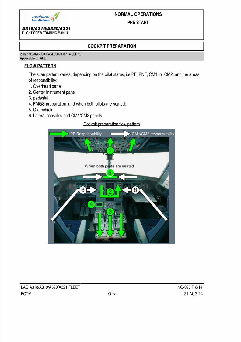
7/21/2019 FCTM date 21-Aug-14
http://slidepdf.com/reader/full/fctm-date-21-aug-14 108/393
A318/A319/A320/A321FLIGHT CREW TRAINING MANUAL
NORMAL OPERATIONS
PRE START
LAO A318/A319/A320/A321 FLEET NO-020 P 8/14
FCTM G → 21 AUG 14
COCKPIT PREPARATION
Ident.: NO-020-00005454.0002001 / 14 SEP 12Applicable to: ALL
FLOW PATTERN
The scan pattern varies, depending on the pilot status, i.e PF, PNF, CM1, or CM2, and the areasof responsibility:1. Overhead panel2. Center instrument panel3. pedestal4. FMGS preparation, and when both pilots are seated:
5. Glareshield6. Lateral consoles and CM1/CM2 panels
Cockpit preparation flow pattern

7/21/2019 FCTM date 21-Aug-14
http://slidepdf.com/reader/full/fctm-date-21-aug-14 109/393
A318/A319/A320/A321FLIGHT CREW TRAINING MANUAL
NORMAL OPERATIONS
PRE START
LAO A318/A319/A320/A321 FLEET NO-020 P 9/14
FCTM ← G → 21 AUG 14
FMGS PROGRAMMING
FMGS programming involves inserting navigation data, then performance data. It is to be notedthat:• Boxed fields must be filled• Blue fields inform the crew that entry is permitted• Green fields are used for FMS generated data, and cannot be changed• Magenta characters identify limits (altitude, speed or time), that FMS will attempt to meet• Yellow characters indicate a temporary flight plan display• Amber characters signify that the item being displayed is important and requires immediate
action
• Small font signifies that data is FMS computed• Large font signifies manually entered data.
This sequence of entry is the most practical. INIT B should not be filled immediately after INIT A,because the FMGS would begin to compute F-PLN predictions. These computations would slowdown the entry procedure.

7/21/2019 FCTM date 21-Aug-14
http://slidepdf.com/reader/full/fctm-date-21-aug-14 110/393

7/21/2019 FCTM date 21-Aug-14
http://slidepdf.com/reader/full/fctm-date-21-aug-14 111/393
A318/A319/A320/A321FLIGHT CREW TRAINING MANUAL
NORMAL OPERATIONS
PRE START
LAO A318/A319/A320/A321 FLEET NO-020 P 11/14
FCTM ← G → 21 AUG 14
• INIT B
The flight crew:‐ Inserts the expected ZFWCG/ZFW, and block fuel to initialize a F-PLN computation.‐ Checks fuel figures consistent with flight preparation fuel figures.
The flight crew will update weight and CG on receipt of the load sheet.The FMS uses the trip wind for the entire flight from origin to destination. The trip wind is anaverage wind component that may be extracted from the CFP. The trip wind facility is availableif the wind profile has not already been entered.After Engine start, the INIT B page is no longer available. The flight crew should use the FUELPRED page for weight and fuel data insertion, if required.
The INIT B page should not be completed immediately after INIT A, because the FMGS wouldbegin to compute F-PLN predictions. This would slow down the entry procedure.
• PERFThe thrust reduction altitude/acceleration altitude (THR RED /ACC) are set to default at 1 500 ft,or at a value defined by airline policy. The THR RED/ACC may be changed in the PERFTAKE-OFF page, if required. The flight crew should consider the applicable noise abatementprocedure.
The one-engine-out acceleration altitude must:‐ Be at least 400 ft above airport altitude‐ Ensure that the net flight path is 35 ft above obstacles‐ Ensure that the maximum time for takeoff thrust is not exceeded.
Therefore, there are generally a minimum and a maximum one engine out acceleration altitudevalues. The minimum value satisfies the first two criteria. The maximum value satisfies the lastone. Any value between those two may be retained.The one engine out acceleration altitude is usually defaulted to 1 500 ft AGL and will be updatedas required.The flight crew uses the PERF CLB page to pre-select a speed. For example, "Green Dot"
speed for a sharp turn after take-off.The crew may also check on the PROG page the CRZ FL, MAX REC FL and OPT FL.Once the FMGS has been programmed, the PNF should then cross check the information prior tothe take-off briefing.When the predictions are available, the crew may print the PREFLIGHT DATA . This listingprovides all the predictions which may be used during the initial part of the flight.
TAKE-OFF BRIEFING
The PF should perform the takeoff briefing at the gate , when the flight crew workload permits,
Cockpit preparation has been completed and, before engine start.

7/21/2019 FCTM date 21-Aug-14
http://slidepdf.com/reader/full/fctm-date-21-aug-14 112/393
A318/A319/A320/A321FLIGHT CREW TRAINING MANUAL
NORMAL OPERATIONS
PRE START
LAO A318/A319/A320/A321 FLEET NO-020 P 12/14
FCTM ← G → 21 AUG 14
The takeoff briefing should be relevant, concise and chronological. When a main parameter isreferred to by the PF, both flight crewmembers must crosscheck that the parameter has been setor programmed correctly. The takeoff briefing covers the following:
Take off briefing with associated checks
1- Miscellaneous
Aircraft type and model (Tail strike awareness)Aircraft technical status (MEL and CDL considerations, relevant OEB)NOTAMSWeather
RWY conditionsUse of ENG/Wing Anti IceENG Start ProcedurePush BackExpected Taxi ClearanceUse of RadarUse of Packs for Takeoff
2- INIT B Page
Block Fuel (1) (FOB on EW/D)Estimated TOWExtra time at destination

7/21/2019 FCTM date 21-Aug-14
http://slidepdf.com/reader/full/fctm-date-21-aug-14 113/393
A318/A319/A320/A321FLIGHT CREW TRAINING MANUAL
NORMAL OPERATIONS
PRE START
LAO A318/A319/A320/A321 FLEET NO-020 P 13/14
FCTM ← G to H → 21 AUG 14
3- Takeoff Perf Page
TO RWY
TO CONFFLEX / TOGA (1) (FLEX TOGA on MCDU)V1, VR, V2 (1) (V1, V2 on PFD)TRANS ALTTHR RED / ACC Altitude
4- Flight Plan
Minimum Safe AltitudeFirst assigned FL (1) (altitude target in blue on PFD)Flight Plan description (1) (SID on MCDU FPLN page)RAD NAV (1) (RAD NAV on ND)
5- Abnormal OperationsFor any failure before V1:
CAPT will call "STOP" or "GO"
In case of failure after V1:continue TO, no actions before 400 ft AGL except gear upreaching 400 ft AGL, ECAM actionsreaching EO ACC altitude
‐ If the engine is secured, level off, accelerate and clean up‐ Otherwise continue climbing until the engine is secured (but not above EO maximum acceleration altitude)
at green dot: OP CLB, MCT, resume ECAM, after TO C/L, statusENG OUT routing: EOSID, SID, radar vector, immediate return ...
(1) Items that must be cross-checked on the associated display.
MISCELLANEOUS
Ident.: NO-020-00005455.0001001 / 25 JUN 08Applicable to: ALL
SEATING POSITION
To achieve a correct seating position, the aircraft is fitted with an eye-position indicator onthe centre windscreen post. The eye-position indicator has two balls on it. When the balls aresuperimposed on each other, they indicate that the pilot's eyes are in the correct position.The flight crew should not sit too low, to avoid increasing the cockpit cut-off angle, thereforereducing the visual segment. During Low Visibility Procedures (LVP), it is important that the pilot'seyes are positioned correctly, in order to maximize the visual segment, and consequently, increasethe possibility of achieving the appropriate visual reference for landing as early as possible.After adjusting the seat, each pilot should adjust the outboard armrest, so that the forearm restscomfortably on it, when holding the sidestick. There should be no gaps between the pilot's forearm
and the armrest. The pilot's wrist should not be bent when holding the sidestick. This ensures that

7/21/2019 FCTM date 21-Aug-14
http://slidepdf.com/reader/full/fctm-date-21-aug-14 114/393
A318/A319/A320/A321FLIGHT CREW TRAINING MANUAL
NORMAL OPERATIONS
PRE START
LAO A318/A319/A320/A321 FLEET NO-020 P 14/14
FCTM ← H 21 AUG 14
the pilot can accomplish flight maneuvers by moving the wrist instead of lifting the forearm fromthe armrest.Symptoms of incorrect armrest adjustment include over-controlling, and not being able to makesmall, precise inputs.The rudder pedals must then be adjusted to ensure the pilot can achieve both full rudder pedaldisplacement and full braking simultaneously on the same side.The armrest and the rudder pedals have position indicators. These positions should be noted andset accordingly for each flight.
MCDU USE
When clear for start up and taxi, the PF will preferably display the MCDU PERF TAKE OFF page
whereas the PNF will display the MCDU F-PLN page.

7/21/2019 FCTM date 21-Aug-14
http://slidepdf.com/reader/full/fctm-date-21-aug-14 115/393
A318/A319/A320/A321FLIGHT CREW TRAINING MANUAL
NORMAL OPERATIONS
START
LAO A318/A319/A320/A321 FLEET NO-030 P 1/4
FCTM A 21 AUG 14
ENGINE AUTO START
Ident.: NO-030-00005456.0002001 / 01 APR 14Applicable to: ALL
1 Engines usually start using the Automatic Starting function. The Full Authority Digital Engine Control(FADEC) systems control this engine Automatic Starting function, and takes appropriate action, ifengine parameters are exceeded. This function extends significantly the duration of engine life.The thrust levers must be confirmed at "idle" before engine-start. If the thrust levers are not at "idle",the thrust increases above idle after engine-start, and can result in a hazardous situation. However,an ENG START FAULT ECAM warning triggers, to indicate that the flight crew must set the thrustlevers to "idle".
The engines are started in sequence, preferably engine 2 first, in order to pressurize yellow hydraulicsystem, which supplies the parking brake accumulator.
When the ENG MODE selector is set to "START", the FADECs are electrically-supplied. When thereis sufficient BLEED PRESS, the PF begins the start sequence by setting the ENG MASTER switch toON. The flight crew should monitor the start sequence:‐ Start valve opens‐ N2 increases‐ IGN A(B)
‐ Fuel flow‐ EGT‐ N1‐ Oil pressure increases‐ Start valve closes‐ IGN indication off (Refer to FCOM/PRO-NOR-SOP-08 Automatic Engine Start )
When the engine is at idle, or when AVAIL is displayed, the PF can start engine 1.The flight crew should check the relative engine vibration level.When the ENG MODE selector is set to NORM, the packs return to the OPEN position. APU Bleed
should immediately be turned off, to avoid engine ingestion of exhaust gas.If the start is not successful, the flight crew must use the ECAM as usually done, and avoidinstinctively selecting the ENG MASTER switch to OFF. This would interrupt the FADEC protectiveactions (e. g. cranking after hot start).

7/21/2019 FCTM date 21-Aug-14
http://slidepdf.com/reader/full/fctm-date-21-aug-14 116/393
A318/A319/A320/A321FLIGHT CREW TRAINING MANUAL
NORMAL OPERATIONS
START
LAO A318/A319/A320/A321 FLEET NO-030 P 2/4
FCTM B to D 21 AUG 14
AVERAGE IDLE ENGINE PARAMETERS
Ident.: NO-030-00005457.0003001 / 26 MAR 08Applicable to: ALL
As soon as the engine-start is complete, the flight crew should check the stabilized parameters. AtISA sea level:
N1 about 19.5 %N2 about 58.5 %EGT about 390 °CFF about 275 kg/h-600 lb/h
ENGINE START MALFUNCTIONIdent.: NO-030-00005458.0001001 / 26 MAR 08Applicable to: ALL
Following an aborted engine start, the crew will consider an engine dry cranking prior resuminga new engine start attempt. Starter limitations in FCOM, Refer to FCOM/LIM-70 Starter , must beobserved.
MANUAL ENGINE START
Ident.: NO-030-00005459.0001001 / 16 NOV 11Applicable to: ALL
The flight crew should only perform a manual start if:• The EGT margins are low• The residual EGT is high• A dry crank is performed.
It may be appropriate to perform a manual start in high altitude operations, or after an aborted enginestart.The MANUAL ENGINE START procedure is a "read and do" procedure. Refer to FCOM/PRO SUP
70 A.Manual Engine Start before starting a manual engine start.The FADEC has limited control over the manual start process. It ensures that the engine start valvecloses at 50 % N2. It monitors engine parameters, and generates an associated warning whennecessary.It is recommended that the flight crew use the stopwatch to ensure that the starter engagement timeremains within the limits.

7/21/2019 FCTM date 21-Aug-14
http://slidepdf.com/reader/full/fctm-date-21-aug-14 117/393
A318/A319/A320/A321FLIGHT CREW TRAINING MANUAL
NORMAL OPERATIONS
START
LAO A318/A319/A320/A321 FLEET NO-030 P 3/4
FCTM E to G → 21 AUG 14
TAILPIPE FIRE
Ident.: NO-030-00005460.0001001 / 01 APR 14Applicable to: ALL
2 An engine tailpipe fire may occur at engine-start, and may be the result of either excess fuel in thecombustion chamber, or an oil leak in the low-pressure turbine. A tailpipe fire is an internal fire withinthe engine. No critical areas are affected.
If the ground crew reports a tailpipe fire, the flight crew must perform the following actions:• Shut down the engine (MASTER switch set to OFF)• Do NOT press the ENG FIRE pushbutton
• Crank the engine, by using either the bleed of the opposite the engine, the APU bleed, or externalpneumatic power (Set ENG MODE selector to CRANK, then set the MAN START switch to ON).
Do NOT use the ENG FIRE pushbutton, this would stop power to the FADECs, and would stopthe motoring sequence. The fire extinguisher must not be used, as it will not extinguish an internalengine fire. As a first priority, the engine must be ventilated.If the ground crew reports a tailpipe fire, and bleed air is not readily available, a groundfire-extinguisher should be used as last resort: Chemical or dry chemical powder causes seriouscorrosive damage to the engine.
ENGINES WARM UP PERIOD
Ident.: NO-030-00005461.0001001 / 16 NOV 11Applicable to: ALL
After engine-start, and in order to avoid thermal shock of the engine, the engine should be operatedat idle or near idle (Refer to FCOM/PRO-NOR-SOP-09 After Start - ENG Mode Selector ) beforesetting the thrust lever to high power. The warm-up can include any taxi time at idle.
AFTER START FLOW PATTERN
Ident.: NO-030-00005462.0001001 / 26 JUN 08Applicable to: ALL
When the engines have started, the PF sets the ENG MODE selector to NORM to permit normalpack operation. At this time, the After Start Flow Pattern begins.

7/21/2019 FCTM date 21-Aug-14
http://slidepdf.com/reader/full/fctm-date-21-aug-14 118/393
A318/A319/A320/A321FLIGHT CREW TRAINING MANUAL
NORMAL OPERATIONS
START
LAO A318/A319/A320/A321 FLEET NO-030 P 4/4
FCTM ← G 21 AUG 14

7/21/2019 FCTM date 21-Aug-14
http://slidepdf.com/reader/full/fctm-date-21-aug-14 119/393
A318/A319/A320/A321FLIGHT CREW TRAINING MANUAL
NORMAL OPERATIONS
TAXI
LAO A318/A319/A320/A321 FLEET NO-040 P 1/10
FCTM A to B → 21 AUG 14
POWERPUSH
Ident.: NO-040-00005463.0003001 / 26 MAR 08Applicable to: ALL
If a Power Push Unit (PPU) is to be used for pushback, the PPU will be placed on the left mainlanding gear and engine 2 will be started at the gate. This will pressurize the yellow hydraulic circuitfor parking brake and NWS. Prior push back, check that there is no NWS DISC memo on the EWD.The flight crew is in charge the steering according to ground indications through the interphone.Due to a face-to-face situation between ground personnel and flight crew, a clear understanding ofdirectional phraseology is essential.The engine 1 will be started when the power push is completed and PPU removed.
During power push, the crew will not use the brakes, unless required due to an emergency and willnot move flight controls or flap lever.In case of emergency, the PPU should be immediately removed out of the evacuation area.Nevertheless, cabin evacuation is possible with the PPU in place.
TAXI ROLL AND STEERING
Ident.: NO-040-00005464.0001001 / 09 APR 14Applicable to: ALL
Before taxi, check that the amber "NWS DISC" ECAM message is off, to ensure that steering is fully
available.1 THRUST USE
The flight crew will need a little power above idle thrust to move the aircraft (approximately up to40 % N1).Excessive thrust application can result in exhaust-blast damage or Foreign Object Damage (FOD).Thrust should normally be used symmetrically.
TILLER AND RUDDER PEDALS USE
Pedals control nosewheel steering at low speed (± 6 ° with full pedal deflection). Therefore, onstraight taxiways and on shallow turns, the pilot can use the pedals to steer the aircraft, keeping ahand on the tiller. In sharper turns, the pilot must use the tiller.
STEERING TECHNIQUE
The Nosewheel steering is "by-wire" with no mechanical connection between the tiller and thenosewheel. The relationship between tiller deflection and nosewheel angle is not linear and thetiller forces are light.

7/21/2019 FCTM date 21-Aug-14
http://slidepdf.com/reader/full/fctm-date-21-aug-14 120/393
A318/A319/A320/A321FLIGHT CREW TRAINING MANUAL
NORMAL OPERATIONS
TAXI
LAO A318/A319/A320/A321 FLEET NO-040 P 2/10
FCTM ← B → 21 AUG 14
Therefore, the PF should move the tiller smoothly and maintain the tiller's position. Any correctionshould be small and smooth, and maintained for enough time to enable the pilot to assess theoutcome. Being over-active on the tiller will cause uncomfortable oscillations.On straight taxiways, the aircraft is correctly aligned on the centerline, when the centerline islined-up between the PFD and ND.
Proper Centerline Following
If both pilots act on the tiller or pedals, their inputs are added until the maximum value of thesteering angle (programmed within the BSCU) is reached.When the seating position is correct, the cut-off angle is 20 °, and the visual ground geometryprovides an obscured segment of 42 ft (12.5 m). During taxi, a turn must be initiated before an

7/21/2019 FCTM date 21-Aug-14
http://slidepdf.com/reader/full/fctm-date-21-aug-14 121/393
A318/A319/A320/A321FLIGHT CREW TRAINING MANUAL
NORMAL OPERATIONS
TAXI
LAO A318/A319/A320/A321 FLEET NO-040 P 3/10
FCTM ← B → 21 AUG 14
obstacle approaches the obscured segment. This provides both wing and tail clearance, withsymmetric thrust and no differential braking.Asymmetric thrust can be used to initiate a tight turn and to keep the aircraft moving during theturn. If nosewheel lateral skidding occurs while turning, reduce taxi speed or increase turn radius.Avoid stopping the aircraft in a turn, because excessive thrust will be required to start the aircraftmoving again.The flight crew should be aware that the main gear on the inside of a turn will always cut thecorner and track inside of the nosewheel track. For this reason, the oversteering technique may beconsidered especially for A321 where main gear is 20 m behind the pilot.
Oversteering Technique
When exiting a tight turn, the pilot should anticipate the steer out. Additionally, the pilot shouldallow the aircraft to roll forward for a short distance to minimize the stress on the main gears.In the event that one or more tires is/are deflated on the main landing gear, the maximumpermitted steering angle will be limited by the aircraft speed. Therefore, with one tire deflated, theaircraft speed is limited to 7 kt and nosewheel steering can be used. With two tires deflated, theaircraft speed is limited to 3 kt and nosewheel steering angle should be limited to 30 °.For turns of 90 ° or more, the aircraft speed should be less than 10 kt.

7/21/2019 FCTM date 21-Aug-14
http://slidepdf.com/reader/full/fctm-date-21-aug-14 122/393
A318/A319/A320/A321FLIGHT CREW TRAINING MANUAL
NORMAL OPERATIONS
TAXI
LAO A318/A319/A320/A321 FLEET NO-040 P 4/10
FCTM ← B 21 AUG 14
180 ° TURN
For turn of 180°, the following procedure is recommended for making a turn in the most efficientway.
For the CM1• Taxi on the right hand side of the runway and turn left to establish a 25 ° divergence from the
runway axis (using the ND or PFD) with a ground speed between 5 kt and 8 kt• When CM1 assesses to be physically over the runway edge on A320/A321 or to be about 2 m
before the runway edge on A318/A319, smoothly initiate a full deflection turn to the right• Asymmetric thrust will be used during the turn. Anticipation is required to ensure that
asymmetric thrust is established before the turn is commenced, between 30 % and 35 % (or
1.02 and 1.03 EPR), to maintain a continuous speed of approximately 5 to 8 kt throughout themanoeuvre
• It is essential to keep minimum ground speed during the turn in order not to need to increasethe thrust too significantly so as not to get stuck. It is a good practice that the CM2 calls the GSfrom ND while in turn
• Differential braking is allowed, but a braked pivot turn is not recommended as a general rule (i.e.braking to fully stop the wheels on one main gear), to avoid stress on the landing gear assembly
• On wet or contaminated runway, more specifically when turning on the runway white oryellow painted marking, tight turn lead to jerky rides of the nose wheel which are noisy and
uncomfortable.For the CM2, the procedure is symmetrical (taxi on the left hand side of the runway).
Aircraft Dimensions

7/21/2019 FCTM date 21-Aug-14
http://slidepdf.com/reader/full/fctm-date-21-aug-14 123/393
A318/A319/A320/A321FLIGHT CREW TRAINING MANUAL
NORMAL OPERATIONS
TAXI
LAO A318/A319/A320/A321 FLEET NO-040 P 5/10
FCTM C to F 21 AUG 14
BRAKE CHECK
Ident.: NO-040-00005466.0002001 / 26 MAR 08Applicable to: ALL
When cleared to taxi, the PF should set the Parking Brake to "OFF". When the aircraft starts tomove, the PF should check the efficiency of the normal braking system by gently pressing the brakepedals.
CARBON BRAKE WEAR
Ident.: NO-040-00005467.0001001 / 26 MAR 08Applicable to: ALL
Carbon brake wear depends on the number of brake applications and on brake temperature. Itdoes not depend on the applied pressure, or the duration of the braking. The temperature at whichmaximum brake wear occurs depends on the brake manufacturer. Therefore, the only way the pilotcan minimize brake wear is to reduce the number of brake applications.
TAXI SPEED AND BRAKING
Ident.: NO-040-00005468.0001001 / 26 MAR 08Applicable to: ALL
On long, straight taxiways, and with no ATC or other ground traffic constraints, the PF should allowthe aircraft to accelerate to 30 kt, and should then use one smooth brake application to decelerate to10 kt. The PF should not "ride" the brakes. The GS indication on the ND should be used to assesstaxi speed.
BRAKE TEMPERATURE
Ident.: NO-040-00005469.0001001 / 23 JUL 10Applicable to: ALL
The FCOM limits brake temperature to 300 °C before takeoff is started.
This limit ensures that, in the case of hydraulic fluid leakage, any hydraulic fluid, that may come intocontact with the brake units, will not be ignited in the wheelwell.This limit does not ensure that, in the case of a high energy rejected takeoff, the maximum brakeenergy limitation will be respected.Thermal oxidation increases at high temperatures. Therefore, if the brakes absorb too much heat,carbon oxidation will increase. This is the reason why the brakes should not be used repeatedly attemperatures above 500 °C during normal operation. In addition, after heavy braking, the use ofbrake fans can increase oxidation of the brake surface hot spots, if the brakes are not thermallyequalized.

7/21/2019 FCTM date 21-Aug-14
http://slidepdf.com/reader/full/fctm-date-21-aug-14 124/393
A318/A319/A320/A321FLIGHT CREW TRAINING MANUAL
NORMAL OPERATIONS
TAXI
LAO A318/A319/A320/A321 FLEET NO-040 P 6/10
FCTM G to I → 21 AUG 14
BRAKING ANOMALIES
Ident.: NO-040-00005470.0002001 / 26 MAR 08Applicable to: ALL
If the ACCU PRESS drops below 1 500 PSI, the flight crew should be aware that the Parking Brakecan, quite suddenly, become less efficient. This explains the amber range on the hydraulic pressuregauge of the ACCU PRESS.If the flight crew encounters any braking problems during taxi, they should set the A/SKID & N/WSTRG Sw to OFF. They should not apply pressure to the pedals while setting the A/SKID & N/WSTRG Sw to OFF. Then, the PF should refer to the triple brake indicator and modulate the pressureas necessary.
BRAKE FANS
Ident.: NO-040-00005471.0001001 / 28 MAY 08Applicable to: ALL
Brake fans cool the brakes, and the brake temperature sensor. Therefore, when the brake fansare running, the indicated brake temperature will be significantly lower than the indicated braketemperature when the brake fans are off.Therefore, as soon as the brake fans are switched on, the indicated brake temperature decreasesalmost instantaneously. On the other hand, when the brake fans are switched off, it will take several
minutes for the indicated brake temperature to increase and match the real brake temperature.When the fans are running, the difference between the indicated and the actual brake temperaturecan range from 50 °C (when the actual brake temperature is 100 °C) to 150 °C (when the actualbrake temperature is 300 °C). Therefore, before takeoff, if the fans are running, the flight crew shouldrefer to the indicated brake temperature. When the indicated brake temperature is above 150 °C,takeoff must be delayed.Brake fans should not be used during takeoff, in order to avoid Foreign Object Damage to fans andbrakes.
FLIGHT CONTROL CHECKIdent.: NO-040-00005472.0001001 / 26 MAR 08Applicable to: ALL
At a convenient stage, before or during taxi, and before arming the autobrake, the PF silently appliesfull longitudinal and lateral sidestick deflection. On the F/CTL page, the PNF checks and calls outfull travel of elevators and ailerons, and correct deflection and retraction of spoilers. As each fulltravel/neutral position is reached, the PNF calls out:• "Full up, full down, neutral"• "Full left, full right, neutral"

7/21/2019 FCTM date 21-Aug-14
http://slidepdf.com/reader/full/fctm-date-21-aug-14 125/393
A318/A319/A320/A321FLIGHT CREW TRAINING MANUAL
NORMAL OPERATIONS
TAXI
LAO A318/A319/A320/A321 FLEET NO-040 P 7/10
FCTM ← I to K → 21 AUG 14
The PF silently checks that the PNF calls are in accordance with the sidestick order. The PF then
presses the PEDAL DISC pb on the nose wheel tiller and silently applies full left and full right rudderand then returns the rudder to neutral. The PNF follows on the rudder pedals and, when each fulltravel/neutral position is reached, calls out:• "Full left, full right, neutral"
Full control input must be held for sufficient time for full travel to be reached and indicated on F/CTLpage.The PNF then applies full longitudinal and lateral sidestick deflection, and on the F/CTL page, silentlychecks full travel and correct sense of all elevators and ailerons, and correct deflection and retractionof all spoilers.
If this check is carried out during taxiing, it is essential that the PF remains head-up throughout theprocedure.
TAKEOFF BRIEFING CONFIRMATION
Ident.: NO-040-00005473.0001001 / 22 OCT 13Applicable to: ALL
The TAKEOFF BRIEFING CONFIRMATION should only review any changes that may haveoccurred since the full TAKEOFF BRIEFING done at the parking bay (e.g. change of SID, change inrunway conditions, etc.).
TAXI WITH ONE ENGINE SHUTDOWN
Ident.: NO-040-00005474.0002001 / 26 MAR 08Applicable to: ALL
Brake life and fuel savings may govern company policy on permitting aircraft to taxi with one engineshut down. However, if taxiing out with one engine shutdown, the crew should be aware of thefollowing:• It is recommended to retain the use of engine 1 during taxi to maintain the green hydraulic system
for normal braking.• Before releasing the parking brake, the yellow electrical pump will be set ON to pressurize theyellow hydraulic circuit (ALT/PARK BRK and NWS) and avoid PTU operation. The crew will checkthe hydraulic yellow accumulator pressure.
• Slow or tight turns in the direction of the operating engine may not be possible at high grossweights.
• It is not possible for ground personnel to protect the engine against fire, when the aircraft movesaway from the ramp.
• The remaining engines should be started with sufficient time for engine warm-up before takeoff.• Any faults encountered during or after starting the remaining engine may require a return to the
gate for maintenance and thus generate a further departure delay.

7/21/2019 FCTM date 21-Aug-14
http://slidepdf.com/reader/full/fctm-date-21-aug-14 126/393
A318/A319/A320/A321FLIGHT CREW TRAINING MANUAL
NORMAL OPERATIONS
TAXI
LAO A318/A319/A320/A321 FLEET NO-040 P 8/10
FCTM ← K to L 21 AUG 14
• Taxi with one engine shut down may require higher thrust than usual. Caution must, therefore, beexercised to avoid excessive jet-blast and the risk of Foreign Object Damage (FOD).
• The use of APU is recommended but the APU bleed should be switched off to avoid ingestion ofexhaust gases by the air conditioning system.
• Before ENG2 start,‐ The yellow is set off to check correct operation of the PTU‐ APU BLEED is set back to ON for ENG2 bleed start.
MISCELLANEOUS
Ident.: NO-040-00005475.0001001 / 28 MAY 08Applicable to: ALL
STROBE LIGHT
When the STROBE lights are set to AUTO, they come on automatically when the aircraft isairborne. The ON position can be used to turn on the lights on ground for crossing, backtracking orentering a runway.
PACKS
If the takeoff has to be achieved without air bleed fed from the engines for performance reasons,but air conditioning desired, the APU bleed may be used with packs ON, thus maintaining engine
performance level and passenger comfort. In case of APU auto shut down during takeoff, theengine thrust is frozen till the thrust is manually reduced. The packs revert to engine bleed whichcauses an increase of EGT to keep N1/EPR.If the takeoff is performed with one pack unserviceable, the procedure states to set the failedpack to OFF. The takeoff may be performed with the other pack ON (if performances permit)with TOGA or FLEX thrust, the pack being supplied by the onside bleed. In this asymmetricbleed configuration, the N1 takeoff value is limited to the value corresponding to the bleed ONconfiguration and takeoff performance must be computed accordingly.

7/21/2019 FCTM date 21-Aug-14
http://slidepdf.com/reader/full/fctm-date-21-aug-14 127/393
A318/A319/A320/A321FLIGHT CREW TRAINING MANUAL
NORMAL OPERATIONS
TAXI
LAO A318/A319/A320/A321 FLEET NO-040 P 9/10
FCTM M 21 AUG 14
TAXI FLOW PATTERN
Ident.: NO-040-00005476.0001001 / 26 MAR 08Applicable to: ALL
TAXI FLOW PATTERN

7/21/2019 FCTM date 21-Aug-14
http://slidepdf.com/reader/full/fctm-date-21-aug-14 128/393
A318/A319/A320/A321FLIGHT CREW TRAINING MANUAL
NORMAL OPERATIONS
TAXI
Intentionally left blank
LAO A318/A319/A320/A321 FLEET NO-040 P 10/10
FCTM 21 AUG 14

7/21/2019 FCTM date 21-Aug-14
http://slidepdf.com/reader/full/fctm-date-21-aug-14 129/393
A318/A319/A320/A321FLIGHT CREW TRAINING MANUAL
NORMAL OPERATIONS
TAKEOFF
LAO A318/A319/A320/A321 FLEET NO-050 P 1/8
FCTM A to B → 21 AUG 14
THRUST SETTING
Ident.: NO-050-00005477.0001001 / 20 DEC 13Applicable to: ALL
The PF should announce "Take-off". The PF then applies power in as follows:
If cross wind is at or below 20 kt and there is no tail wind
• From idle to 1.05 EPR / 50 % N1 by reference to the TLA indicator on the EPR / N1 gauge.• When the engine parameters have stabilized, to the FLX/MCT or TOGA detent as appropriate.
In case of tailwind or if cross wind is greater than 20 kt:
• From idle to 1.05 EPR / 50 % N1 by reference to the TLA indicator on the EPR / N1 gauge.• Once stabilized, from 1.05 EPR / 50 % N1 to 1.15 EPR / 70 % N1 by reference to the TLA
indicator on the EPR / N1 gauge.• Then, to FLX / TOGA, as required to reach take-off thrust at 40 kt groundspeed.
This procedure ensures that all engines will accelerate similarly. If not properly applied, this may leadto asymmetrical thrust increase, and, consequently, to severe directional control problem.
If the thrust levers are not set to the proper take-off detent, e.g. FLX instead of TOGA, a messagecomes up on the ECAM.
TAKEOFF ROLL
Ident.: NO-050-00005478.0001001 / 23 APR 13
Applicable to: ALL
Once the thrust is set, the PF announces the indications on the FMA. The PNF must check that thethrust is set by 80 kt and must announce "Thrust Set".
The Captain must keep his hand on the thrust levers when the thrust levers are set to TOGA/FLXnotch and until V1.
On a normal takeoff, to counteract the pitch up moment during thrust application, the PF should apply
half forward (full forward in cross wind case) sidestick at the start of the takeoff roll until reaching80 kt. At this point, the input should be gradually reduced to be zero by 100 kt.

7/21/2019 FCTM date 21-Aug-14
http://slidepdf.com/reader/full/fctm-date-21-aug-14 130/393
A318/A319/A320/A321FLIGHT CREW TRAINING MANUAL
NORMAL OPERATIONS
TAKEOFF
LAO A318/A319/A320/A321 FLEET NO-050 P 2/8
FCTM ← B to D → 21 AUG 14
The PF should use pedals to keep the aircraft straight. The nosewheel steering authority decreases
at a pre-determined rate as the groundspeed increases (no more efficiency at 130 kt) and the rudderbecomes more effective. The use the tiller is not recommended during takeoff roll, because of its high
efficiency, which might lead to aircraft overreaction.For crosswind takeoffs, routine use of into wind aileron is not necessary. In strong crosswindconditions, small lateral stick input may be used to maintain wings level, if deemed necessary due to
into wind wing reaction, but avoid using large deflections, resulting in excessive spoiler deploymentwhich increase the aircraft tendency to turn into the wind (due to high weight on wheels on the spoiler
extended side), reduces lift and increases drag. Spoiler deflection becomes significant with morethan a third sidestick deflection.
In the event of unexpected lateral disturbance during takeoff roll, the flight crew should use therudder as for counteracting any lateral disturbance. Indeed, excessive rudder input may increasethe magnitude of the lateral disturbance. The flight crew may be surprised during takeoff roll byunexpected lateral disturbance in conditions such as:
‐ The presence of thermals or thermal vortices that often develop in hot and dry countries.Sometimes, these thermal streams get stronger, and create small whirlwinds referred to as "dust
devils", or‐ The jet blast of another aircraft close to the active runway, or‐ The wind that accelerates between two buildings by "venturi" effect.
As the aircraft lifts off, any lateral stick input applied will result in a roll rate demand, making aircraftlateral control more difficult. Wings must be level.In case of low visibility takeoff, visual cues are primary means to track the runway centerline. The
PFD yaw bar provides an assistance in case of expected fog patches if ILS available.
TYPICAL AIRCRAFT ATTITUDE AT TAKEOFF AFTER LIFT-OFF
Ident.: NO-050-00005479.0001001 / 26 MAR 08
Applicable to: ALL
At take off, the typical all engine operating attitude after lift-off is about 15 °.
ROTATION
Ident.: NO-050-00005480.0001001 / 20 MAY 09
Applicable to: ALL
Rotation is conventional. During the takeoff roll and the rotation, the pilot flying scans rapidly the
outside references and the PFD. Until airborne, or at least until visual cues are lost, this scanningdepends on visibility conditions (the better the visibility, the higher the priority given to outsidereferences). Once airborne, the PF must then controls the pitch attitude on the PFD using FD bars in
SRS mode which is then valid.
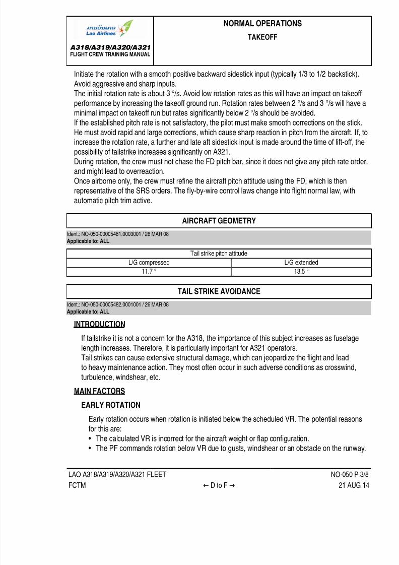
7/21/2019 FCTM date 21-Aug-14
http://slidepdf.com/reader/full/fctm-date-21-aug-14 131/393
A318/A319/A320/A321FLIGHT CREW TRAINING MANUAL
NORMAL OPERATIONS
TAKEOFF
LAO A318/A319/A320/A321 FLEET NO-050 P 3/8
FCTM ← D to F → 21 AUG 14
Initiate the rotation with a smooth positive backward sidestick input (typically 1/3 to 1/2 backstick).
Avoid aggressive and sharp inputs.The initial rotation rate is about 3 °/s. Avoid low rotation rates as this will have an impact on takeoff
performance by increasing the takeoff ground run. Rotation rates between 2 °/s and 3 °/s will have aminimal impact on takeoff run but rates significantly below 2 °/s should be avoided.If the established pitch rate is not satisfactory, the pilot must make smooth corrections on the stick.
He must avoid rapid and large corrections, which cause sharp reaction in pitch from the aircraft. If, toincrease the rotation rate, a further and late aft sidestick input is made around the time of lift-off, the
possibility of tailstrike increases significantly on A321.During rotation, the crew must not chase the FD pitch bar, since it does not give any pitch rate order,and might lead to overreaction.
Once airborne only, the crew must refine the aircraft pitch attitude using the FD, which is thenrepresentative of the SRS orders. The fly-by-wire control laws change into flight normal law, with
automatic pitch trim active.
AIRCRAFT GEOMETRY
Ident.: NO-050-00005481.0003001 / 26 MAR 08Applicable to: ALL
Tail strike pitch attitude
L/G compressed L/G extended
11.7 ° 13.5 °
TAIL STRIKE AVOIDANCE
Ident.: NO-050-00005482.0001001 / 26 MAR 08
Applicable to: ALL
INTRODUCTION
If tailstrike it is not a concern for the A318, the importance of this subject increases as fuselage
length increases. Therefore, it is particularly important for A321 operators.
Tail strikes can cause extensive structural damage, which can jeopardize the flight and leadto heavy maintenance action. They most often occur in such adverse conditions as crosswind,
turbulence, windshear, etc.
MAIN FACTORS
EARLY ROTATION
Early rotation occurs when rotation is initiated below the scheduled VR. The potential reasons
for this are:• The calculated VR is incorrect for the aircraft weight or flap configuration.
• The PF commands rotation below VR due to gusts, windshear or an obstacle on the runway.

7/21/2019 FCTM date 21-Aug-14
http://slidepdf.com/reader/full/fctm-date-21-aug-14 132/393
A318/A319/A320/A321FLIGHT CREW TRAINING MANUAL
NORMAL OPERATIONS
TAKEOFF
LAO A318/A319/A320/A321 FLEET NO-050 P 4/8
FCTM ← F → 21 AUG 14
Whatever the cause of the early rotation, the result will be an increased pitch attitude at lift-off,
and consequently a reduced tail clearance.
ROTATION TECHNIQUE
The recommendation given in the ROTATION TECHNIQUE paragraph should be applied.A fast rotation rate increases the risk of tailstrike, but a slow rate increases take-off distance.
The recommended rate is about 3 °/s, which reflects the average rates achieved during flighttest, and is also the reference rate for performance calculations.
CONFIGURATION (NOT APPLICABLE TO A318)
When performance is limiting the takeoff weight, the flight crew uses TOGA thrust and selects
the configuration that provides the highest takeoff weight.When the actual takeoff weight is lower than the permissible one, the flight crew uses FLEX TO
thrust. For a given aircraft weight, a variety of flap configurations are possible. Usually, the flightcrew selects the configuration that provides the maximum FLEX temperature. This is done toprolong engine life. The first degrees of flexible thrust have an impact on maintenance costs
about 5 times higher than the last one.The configuration that provides the maximum FLEX temperature varies with the runway length.
On short runways, CONF 3 usually provides the highest FLEX temperature, and the tailclearance at lift off does not depends on the configuration.
On medium or long runways, the second segment limitation becomes the limiting factor, andCONF 2 or CONF 1+F becomes the optimum configuration, in term of FLEX temperature.In these cases, the tail clearance at lift off depends on the configuration. The highest flap
configuration gives the highest tailstrike margin.
TAKEOFF TRIM SETTING
The main purpose of the pitch trim setting for take-off is to provide consistent rotationcharacteristics. Take-off pitch trim is set manually via the pitch trim wheel.
The aircraft performs a safe takeoff, provided the pitch trim setting is within the green band onthe pitch trim wheel.
However, the pitch trim setting significantly affects the aircraft behaviour during rotation:
• With a forward CG and the pitch trim set to the nose-down limit the pilots will feel an aircraft"heavy to rotate" and aircraft rotation will be very slow in response to the normal take off stick
displacement.• With an aft CG and the pitch trim set to the nose-up limit the pilots will most probably have to
counteract an early autorotation until VR is reached.
In either case the pilot may have to modify his normal control input in order to achieve thedesired rotation rate, but should be cautious not to overreact.

7/21/2019 FCTM date 21-Aug-14
http://slidepdf.com/reader/full/fctm-date-21-aug-14 133/393
A318/A319/A320/A321FLIGHT CREW TRAINING MANUAL
NORMAL OPERATIONS
TAKEOFF
LAO A318/A319/A320/A321 FLEET NO-050 P 5/8
FCTM ← F to H → 21 AUG 14
CROSSWIND TAKEOFF
It is said in the TAKEOFF ROLL paragraph that care should be taken to avoid using largedeflection, resulting in excessive spoiler deployment. A direct effect of the reduction in lift due tothe extension of the spoilers on one wing will be a reduction in tail clearance and an increased
risk of tailstrike.
OLEO INFLATION
The correct extension of the main landing gear shock absorber (and thus the nominal increasein tail clearance during the rotation) relies on the correct inflation of the oleos.
ACTION IN CASE OF TAILSTRIKE
If a tailstrike occurs at take-off, flight at attitude requiring a pressurized cabin must be avoided anda return to the originating airport should be performed for damage assessment.
THRUST REDUCTION ALTITUDE
Ident.: NO-050-00005487.0001001 / 28 MAY 08
Applicable to: ALL
At the thrust reduction altitude, "LVR CLB" flashes on the FMA. When manual flying, lower slightlythe nose, as applicable, to anticipate the pitch down FD order. Bring the thrust levers back to CLB
detent. The A/THR is now active (A/THR on the FMA changes from blue to white).The FD pitch down order depends upon the amount of thrust decrease between TOGA or FLX andCLB.
If takeoff was performed packs OFF, the packs will be selected back to ON after thrust reductionbecause of the potential resulting EGT increase. They will be preferably selected sequentially toimprove passenger's comfort.
ACCELERATION ALTITUDE
Ident.: NO-050-00005488.0001001 / 01 APR 14
Applicable to: ALL
1
At the acceleration altitude, the FD pitch mode changes from SRS to CLB or OP CLB mode. Thespeed target jumps:
• Either to the managed target speed e.g. speed constraint, speed limit or ECON climb speed• Or to the preselected climb speed (entered by the pilot on the MCDU PERF CLB page before
takeoff).
If green dot speed is higher than the managed target speed (e.g. speed constraint 220 kt) displayedby the magenta triangle on the PFD speed scale, the AP/FD will guide the aircraft to green dot (as

7/21/2019 FCTM date 21-Aug-14
http://slidepdf.com/reader/full/fctm-date-21-aug-14 134/393
A318/A319/A320/A321FLIGHT CREW TRAINING MANUAL
NORMAL OPERATIONS
TAKEOFF
LAO A318/A319/A320/A321 FLEET NO-050 P 6/8
FCTM ← H to J → 21 AUG 14
per the general managed speed guidance rule). If required by ATC, the crew will select the adequate
target speed (below green dot) on the FCU.
During takeoff phase, F and S speeds are the minimum speeds for retracting the surfaces:• At F speed, the aircraft accelerating (positive speed trend): retract to 1.
• At S speed, the aircraft accelerating (positive speed trend): retract to 0.
If the ENG MODE selector had been selected to IGN START for take-off, the PNF should confirmwith the PF when it may be deselected.
TAKE-OFF AT HEAVY WEIGHT
Ident.: NO-050-00005489.0001001 / 07 OCT 13
Applicable to: ALL
If take-off is carried out at heavy weight, two protections may intervene:• The Automatic Retraction System (ARS)
• The Alpha Lock function
THE AUTOMATIC RETRACTION SYSTEM
While in CONF 1+F and IAS reaches 210 kt (VFE CONF1+F is 215 kt or 225 kt on someA321, Refer to FCOM/LIM-13 Maximum Flaps/Slats Speeds ), the ARS is activated. The ARS
automatically retracts flaps to 0 °. The VFE displayed on the PFD change from VFE CONF1+F to
VFE CONF 1. As the aircraft accelerates above S speed, the flap lever can be selected to 0. If IASdecreases below VFE CONF1+F, the flaps will not extend back to 1+F.
THE ALPHA LOCK FUNCTION
The slats alpha/speed lock function will prevent slat retraction at high AOA or low speed at themoment the flap lever is moved from Flaps 1 to Flaps 0. "A. LOCK" pulses above the E/WD Slat
indication. The inhibition is removed and the slats retract when both alpha and speed fall withinnormal values. This is a normal situation for take-off at heavy weight. If Alpha lock function istriggered, the crew will continue the scheduled acceleration, allowing further slats retraction.
OVERSPEED WARNING DURING SLATS/FLAPS TRANSITION
2 Ident.: NO-050-00015267.0001001 / 27 MAR 14
Applicable to: ALL
During the Slats/Flaps transition, the flight crew must respect the VMAX displayed on the PFD. TheVMAX value displayed on the PFD speed scale is based on the Slats/Flaps control lever position.
The OVERSPEED WARNING is based on the actual Slats/Flaps surface position. Therefore,during Slats/Flaps transition, the dynamic acceleration of the airplane may lead to a temporary

7/21/2019 FCTM date 21-Aug-14
http://slidepdf.com/reader/full/fctm-date-21-aug-14 135/393
A318/A319/A320/A321FLIGHT CREW TRAINING MANUAL
NORMAL OPERATIONS
TAKEOFF
LAO A318/A319/A320/A321 FLEET NO-050 P 7/8
FCTM ← J to M → 21 AUG 14
OVERSPEED WARNING even if the current speed is out of the red and black strip displayed on the
PFD. In this situation, there are no operational consequences.
IMMEDIATE TURN AFTER TAKE-OFF
Ident.: NO-050-00005490.0001001 / 26 MAR 08Applicable to: ALL
Obstacle clearance, noise abatement, or departure procedures may require an immediate turn
after take-off. Provided FD commands are followed accurately, the flaps and slats may be retractedusing the normal procedure as FD orders provide bank angle limits with respect to speed and
configuration.
LOW ALTITUDE LEVEL-OFF
Ident.: NO-050-00005491.0001001 / 26 MAR 08
Applicable to: ALL
If the aircraft is required to level off below the acceleration altitude, ALT* engages and target speed
goes to initial climb speed. The "LVR CLB" message flashes on the FMA. In this case, the crewshould expect a faster than normal acceleration, and be prepared to retract the flaps and slats
promptly.
NOISE ABATEMENT TAKE-OFF
Ident.: NO-050-00005492.0001001 / 07 MAY 13
Applicable to: ALL
Noise Abatement Procedures will not be conducted in conditions of significant turbulence or
windshear.

7/21/2019 FCTM date 21-Aug-14
http://slidepdf.com/reader/full/fctm-date-21-aug-14 136/393
A318/A319/A320/A321FLIGHT CREW TRAINING MANUAL
NORMAL OPERATIONS
TAKEOFF
LAO A318/A319/A320/A321 FLEET NO-050 P 8/8
FCTM ← M 21 AUG 14
NOISE ABATEMENT TAKE-OFF

7/21/2019 FCTM date 21-Aug-14
http://slidepdf.com/reader/full/fctm-date-21-aug-14 137/393
A318/A319/A320/A321FLIGHT CREW TRAINING MANUAL
NORMAL OPERATIONS
CLIMB
LAO A318/A319/A320/A321 FLEET NO-060 P 1/4
FCTM A to B → 24 AUG 11
GENERAL
Ident.: NO-060-00005493.0001001 / 26 MAR 08Applicable to: ALL
During the climb, the thrust levers are in the CL detent, the A/THR is active in thrust mode and theFADECs manage the thrust to a maximum value depending upon ambient conditions.
AP/FD CLIMB MODES
Ident.: NO-060-00005494.0005001 / 26 MAR 08Applicable to: ALL
The AP/FD climb modes may be either
• Managed• Selected
MANAGED
The managed AP/FD mode in climb is CLB. Its use is recommended as long as the aircraft iscleared along the F-PLN.
SELECTED
The selected AP/FD modes in climb are OP CLB, V/S and EXPED .
OP CLB is to be used if ATC gives radar vector or clears the aircraft direct to a given FL withoutany climb constraints.The use of low values of V/S, e.g. less than 1 000 ft/min, may be appropriate for small altitudechanges as it makes the guidance smoother and needs less thrust variation.In areas of high traffic density, low values of vertical speed will reduce the possibility of nuisanceTCAS warnings.If the crew selects a high V/S, it may happen that the aircraft is unable to climb with this high V/Sand to maintain the target speed with Max Climb thrust, for performance reasons. In that case,the AP/FD will guide to the target V/S, and the A/THR will command up to Max Climb thrust, in
order to try to keep the target speed; but the aircraft will decelerate and its speed might reachVLS. When VLS is reached the AP will pitch the aircraft down so as to fly a V/S, which allowsmaintaining VLS. A triple click is generated.Whenever V/S is used, pilots should pay particular attention to the speed trend as V/S takesprecedence over speed requirements.The EXPED mode is used to climb with maximum vertical gradient i.e. the target speedbecomes green dot. Its use should be avoided above FL 250.The crew should be aware that altitude constraints in the MCDU F-PLN page are observed onlywhen the climb is managed, i.e. when CLB is displayed on the FMA. Any other vertical mode willdisregard any altitude constraints.

7/21/2019 FCTM date 21-Aug-14
http://slidepdf.com/reader/full/fctm-date-21-aug-14 138/393
A318/A319/A320/A321FLIGHT CREW TRAINING MANUAL
NORMAL OPERATIONS
CLIMB
LAO A318/A319/A320/A321 FLEET NO-060 P 2/4
FCTM ← B to C → 24 AUG 11
A likely scenario would be, when the FCU altitude is set above an altitude constraint and the pilotselects V/S when below that constraint to avoid a potential TCAS TA. In this case, the aircraft willdisregard the altitude constraint.
SPEED CONSIDERATIONS
Ident.: NO-060-00005495.0001001 / 26 MAR 08Applicable to: ALL
The climb speed may be either:• Managed• Selected
MANAGED
The managed climb speed, computed by the FMGS, provides the most economical climb profileas it takes into account weight, actual and predicted winds, ISA deviation and Cost Index (CI). Themanaged climb speed also takes into account any speed constraints, e.g. the default speed limitwhich is 250 kt up to 10 000 ft.
SELECTED
If necessary, the climb speed can be either pre-selected on ground prior to take-off on the MCDUPERF CLIMB page or selected on the FCU as required.
On ground, prior take-off, speed target at acceleration altitude can be pre-selected on the MCDUPERF CLIMB page. It is to be used when the F-PLN has a sharp turn after take-off, when highangle of climb is required or for ATC clearance compliance.Once airborne, the speed can be selected on FCU to achieve the maximum rate of climb or themaximum gradient of climb.The speed to achieve the maximum rate of climb, i.e. to reach a given altitude in the shortest time,lies between ECON climb speed and green dot. As there is no indication of this speed on the PFD,a good rule of thumb is to use turbulence speed to achieve maximum rate.The speed to achieve the maximum gradient of climb, i.e. to reach a given altitude in a shortest
distance, is green dot. The MCDU PERF CLB page displays the time and distance required toachieve the selected altitude by climbing at green dot speed. Avoid reducing to green dot at highaltitude, particularly at heavy weight, as it can take a long time to accelerate to ECON mach.Pilots should be aware that it is possible to select and fly a speed below green dot but there wouldbe no operational benefit in doing this.When selected speed is used, the predictions on the F-PLN page assume the selected speedis kept till the next planned speed modification, e.g. 250 kt /10 000 ft, where managed speed issupposed to be resumed. Consequently, the FM predictions remain meaningful.When IAS is selected in lower altitude, there is an automatic change to Mach at a specific
crossover altitude.

7/21/2019 FCTM date 21-Aug-14
http://slidepdf.com/reader/full/fctm-date-21-aug-14 139/393
A318/A319/A320/A321FLIGHT CREW TRAINING MANUAL
NORMAL OPERATIONS
CLIMB
LAO A318/A319/A320/A321 FLEET NO-060 P 3/4
FCTM ← C to E 24 AUG 11
Finally, as selected speed does not provide the optimum climb profile, it should only be used whenoperationally required, e.g. ATC constraint or weather.
VERTICAL PERFORMANCE PREDICTIONS
Ident.: NO-060-00005496.0001001 / 27 MAY 08Applicable to: ALL
The MCDU PROG page provides the crew with the MAX REC ALT and with the OPT ALTinformation (See cruise section). This information is to be used to rapidly answer to ATC: "CAN YOUCLIMB TO FL XXX?"The MCDU PERF CLB page provides predictions to a given FL in terms of time and distance
assuming CLB mode. This FL is defaulted to the FCU target altitude or it may be manually inserted.The level arrow on the ND assumes the current AP engaged mode. This information is to be usedto rapidly answer to ATC: "CAN YOU MAKE FL XXX by ZZZ waypoint?". The crew will use a PD(Place/Distance), i.e. ZZZ,-10 waypoint if the question is "CAN YOU MAKE FL XXX , 10 nm beforeZZZ point?"
LATERAL NAVIGATION
Ident.: NO-060-00005497.0001001 / 26 MAR 08Applicable to: ALL
If the aircraft is following the programmed SID, the AP/FD should be in NAV. If ATC vectors theaircraft, HDG will be used until a time when clearance is given to either resume the SID or trackdirect to a specific waypoint. In either case, the crew must ensure that the waypoints are properlysequenced.The crew should keep in mind that the use of HDG mode e.g. following ATC radar vectors, will revertCLB to OP CLB and any altitude constraints in the MCDU F-PLN page will not be observed unlessthey are selected on the FCU.

7/21/2019 FCTM date 21-Aug-14
http://slidepdf.com/reader/full/fctm-date-21-aug-14 140/393
A318/A319/A320/A321FLIGHT CREW TRAINING MANUAL
NORMAL OPERATIONS
CLIMB
LAO A318/A319/A320/A321 FLEET NO-060 P 4/4
FCTM F 24 AUG 11
10 000 FT FLOW PATTERN
Ident.: NO-060-00005498.0001001 / 26 MAR 08Applicable to: ALL
10 000 ft FLOW PATTERN
EFIS Option:The PF will select CSTR for grid MORAThe PNF will select ARPT

7/21/2019 FCTM date 21-Aug-14
http://slidepdf.com/reader/full/fctm-date-21-aug-14 141/393
A318/A319/A320/A321FLIGHT CREW TRAINING MANUAL
NORMAL OPERATIONS
CRUISE
LAO A318/A319/A320/A321 FLEET NO-070 P 1/10
FCTM A to B → 06 MAR 14
PREFACE
Ident.: NO-070-00005499.0002001 / 26 MAR 08Applicable to: ALL
Once the cruise flight level is reached, "ALT CRZ" is displayed on the FMA. The cruise Mach number
is targeted and cruise fuel consumption is optimized.
FMS USE
Ident.: NO-070-00005500.0002001 / 28 FEB 14
Applicable to: ALL
CRUISE FL
If the aircraft is cleared to a lower cruise flight level than the pre-planned cruise flight level
displayed on MCDU PROG page, the cruise Mach number will not be targeted. The crew willupdate the MCDU PROG page accordingly.
When at cruise FL, the AP altitude control is soft. This means that the AP will allow small altitudevariation around the cruise altitude (typically ± 50 ft) to keep cruise Mach before a readjustment ofthrust occurs. This optimizes the fuel consumption in cruise.
WIND AND TEMPERATURE
When reaching cruise FL, the crew will ensure that the wind and temperatures are correctlyentered and the lateral and vertical F-PLN reflect the CFP. Wind entries should be made atwaypoints when there is a difference of either 30 ° or 30 kt for the wind data and 5 °C for
temperature deviation. These entries should be made for as many levels as possible to reflect theactual wind and temperature profile. This will ensure that the FMS fuel and time predictions are as
accurate as possible and provide an accurate OPT FL computation.
STEP CLIMB
If there is a STEP in the F-PLN, the crew will ensure that the wind is properly set at the firstwaypoint beyond the step (D on the following example) at both initial FL and step FL.

7/21/2019 FCTM date 21-Aug-14
http://slidepdf.com/reader/full/fctm-date-21-aug-14 142/393
A318/A319/A320/A321FLIGHT CREW TRAINING MANUAL
NORMAL OPERATIONS
CRUISE
LAO A318/A319/A320/A321 FLEET NO-070 P 2/10
FCTM ← B → 06 MAR 14
If at D waypoint, the CFP provides the wind at FL 350 but not at FL 310, it is recommended toinsert the same wind at FL 310 as the one at FL 350. This is due to wind propagation rules, whichmight affect the optimum FL computation.
ETP
ETP function should be used to assist the crew in making a decision should an en-route diversionbe required. Suitable airport pairs should be entered on the ETP page and the FMS will then
calculate the ETP. Each time an ETP is sequenced, the crew should insert the next suitablediversion airfield.
The SEC F-PLN is a useful tool and should be used practically. The ETP should be inserted in the
SEC F-PLN as a PD (Place/Distance) and the route to diversion airfield should be finalized. Byprogramming a potential en-route diversion, the crew would reduce their workload should a failureoccur. This is particularly true when terrain considerations apply to the intended diversion route.
When an ETP is sequenced, the crew will• Access the ETP page
• Insert the next applicable diversion airfield with associated wind• Read new ETP• Insert new ETP as a PD
• Copy active on the SEC F-PLN• Insert the new diversion as New Dest in the SEC F-PLN from new ETP.

7/21/2019 FCTM date 21-Aug-14
http://slidepdf.com/reader/full/fctm-date-21-aug-14 143/393
A318/A319/A320/A321FLIGHT CREW TRAINING MANUAL
NORMAL OPERATIONS
CRUISE
LAO A318/A319/A320/A321 FLEET NO-070 P 3/10
FCTM ← B to C → 06 MAR 14
The DATA/Stored Routes function in the MCDU can be used to store up to five possible diversionroutes. These routes can be entered into the SEC F-PLN using the SEC INIT prompt. This promptwill only be available if the SEC F-PLN is deleted. Refer to FCOM/DSC-22_20-60-30 Using the
Secondary Flight Plan Function for further information.
CLOSEST AIRPORT
For diversion purpose, the crew can also use the CLOSEST AIRPORT page which providesvaluable fuel/time estimates to the four closest airports from the aircraft position, as well as to
an airport the crew may define. The fuel and time predictions are a function of the average wind
between the aircraft and the airport.
FMS USE: MISCELLANEOUS
Ident.: NO-070-00005501.0002001 / 26 MAY 08
Criteria: P7519, SA
Applicable to: MSN 5356-5396
If ATC requires a position report, the crew will use the REPORT page which can be accessed fromPROG page.
If ATC modifies the routing, the crew will revise the F-PLN. Once achieved and if printer is installed,
the crew may perform a new F-PLN print.

7/21/2019 FCTM date 21-Aug-14
http://slidepdf.com/reader/full/fctm-date-21-aug-14 144/393
A318/A319/A320/A321FLIGHT CREW TRAINING MANUAL
NORMAL OPERATIONS
CRUISE
LAO A318/A319/A320/A321 FLEET NO-070 P 4/10
FCTM ← C to D → 06 MAR 14
ATC requires a report on a given radial, the crew will use the FIX INFO page which can be accessed
from a lateral revision on F-PLN page at PPOS.If ATC requires a report at a given time, the crew will insert a time marker pseudo waypoint.
If there is weather, the crew will use the OFFSET function which can be accessed from a lateralrevision at PPOS. The crew will determine how many NM are required to avoid the weather. Oncecleared by ATC, the crew will insert the offset.
If ATC gives a DIR TO clearance to a waypoint far from present position, the crew will use theABEAM facility. This facility allows both a better crew orientation and the previously entered winds to
be still considered.
FMS USE: MISCELLANEOUS
Ident.: NO-070-00005501.0003001 / 26 MAR 08
Criteria: P7373, P7519, P7666, SA
Applicable to: MSN 4596-4639
If ATC modifies the routing, the crew will revise the F-PLN. Once achieved and if printer is installed,
the crew may perform a new F-PLN print.If there is weather, the crew will use the OFFSET function which can be accessed from a lateralrevision at PPOS. The crew will determine how many NM are required to avoid the weather. Once
cleared by ATC, the crew will insert the offset.If ATC gives a DIR TO clearance to a waypoint far from present position, the crew will use the
ABEAM facility. This facility allows both a better crew orientation and the previously entered winds tobe still considered.
COST INDEX
Ident.: NO-070-00005502.0001001 / 27 JUN 12
Applicable to: ALL
The Cost Index (CI) is used to take into account the relationship between fuel and time relatedcosts in order to minimize the trip cost. The CI is calculated by the airline for each sector. From an
operational point of view, the CI affects the speeds (ECON SPEED/MACH) and cruise altitude (OPTALT). CI=0 corresponds to maximum range whereas the CI=999 corresponds to minimum time.The CI is a strategic parameter which applies to the whole flight. However, the CI can be modified
by the crew in flight for valid strategic operational reasons. For example, if the crew needs to reducethe speed for the entire flight to comply with curfew requirements or fuel management requirements
(XTRA gets close to 0), then it is appropriate to reduce the CI.The SEC F-PLN can be used to check the predictions associated with new CI. If they aresatisfactory, the crew will then modify the CI in the primary The SEC F-PLN can be used to check
the predictions associated with new CI. If they are satisfactory, the crew will then modify the CI in the

7/21/2019 FCTM date 21-Aug-14
http://slidepdf.com/reader/full/fctm-date-21-aug-14 145/393
A318/A319/A320/A321FLIGHT CREW TRAINING MANUAL
NORMAL OPERATIONS
CRUISE
LAO A318/A319/A320/A321 FLEET NO-070 P 5/10
FCTM ← D to E 06 MAR 14
primary F-PLN. However, the crew should be aware that any modification of the CI would affect trip
cost.
SPEED CONSIDERATIONS
Ident.: NO-070-00005503.0002001 / 26 MAR 08Applicable to: ALL
The cruise speed may be either:
• Managed• Selected
MANAGED
When the cruise altitude is reached, the A/THR operates in SPEED/MACH mode. The optimum
cruise Mach number is automatically targeted. Its value depends on:• CI
• Cruise flight level• Temperature deviation• Weight
• Headwind component.
The crew should be aware that the optimum Mach number will vary according to the above
mentioned parameters, e.g. it will increase with an increasing headwind, e.g. +50 kt head windequates to M +0.01.Should ATC require a specific time over a waypoint, the crew can perform a vertical revision
on that waypoint and enter a time constraint. The managed Mach number would be modifiedaccordingly to achieve this constraint. If the constraint can be met within a tolerance, a magenta
asterix will be displayed on the MCDU; if the constraint cannot be met, an amber asterix will bedisplayed. Once the constrained waypoint is sequenced, the ECON Mach is resumed.
SELECTED
Should ATC require a specific cruise speed or turbulence penetration is required, the pilot must
select the cruise speed on the FCU. FMS predictions are updated accordingly until reachingeither the next step climb or top of descent, where the programmed speeds apply again. The FMSpredictions are therefore realistic.
At high altitude, the speed should not be reduced below GREEN DOT as this may create asituation where it is impossible to maintain speed and/or altitude as the increased drag may
exceed the available thrust.

7/21/2019 FCTM date 21-Aug-14
http://slidepdf.com/reader/full/fctm-date-21-aug-14 146/393
A318/A319/A320/A321FLIGHT CREW TRAINING MANUAL
NORMAL OPERATIONS
CRUISE
LAO A318/A319/A320/A321 FLEET NO-070 P 6/10
FCTM F to G → 06 MAR 14
ALTITUDE CONSIDERATIONS
Ident.: NO-070-00005504.0001001 / 21 NOV 11Applicable to: ALL
The MCDU PROG page displays:
• REC MAX FL• OPT FL.
REC MAX FL
REC MAX FL reflects the present engine and wing performance and does not take into account
the cost aspect. It provides a 0.3 gbuffet margin. If the crew inserts a FL higher than REC MAX
into the MCDU, it will be accepted only if it provides a buffet margin greater than 0.2 g. Otherwise,it will be rejected and the message "CRZ ABOVE MAX FL" will appear on the MCDU scratchpad.
This message may also be triggered in case of temperature increase leading the aircraft to flyabove the REC MAX FL. Unless there are overriding operational considerations, e.g. either to
accept a cruise FL higher than REC MAX or to be held significantly lower for a long period, RECMAX should be considered as the upper cruise limit.
OPT FL
OPT FL displayed on the MCDU is the cruise altitude for minimum cost when ECON MACH is
flown and should be followed whenever possible. It is important to note that the OPT FL displayedon the PROG page is meaningful only if the wind and temperature profile has been accurately
entered. The crew should be aware that flying at a level other than the OPT FL would adverselyaffect the trip cost.For each Mach number, there will be a different OPT FL. Should an FMGS failure occur, the crew
should refer to the FCOM or QRH to determine the OPT FL. FCOM and QRH charts are onlyprovided for two different Mach numbers.
SPEED DECAY DURING CRUISE
Ident.: NO-070-00015120.0001001 / 01 AUG 13
Applicable to: ALL
FACTORS THAT CAUSE A SPEED DECAY DURING CRUISE
On aircraft with no failure, and the A/THR engaged or the MAX CLB Thrust applied in manualmode, a continuous speed decay during cruise phase may be due to:
7/21/2019 FCTM date 21-Aug-14
http://slidepdf.com/reader/full/fctm-date-21-aug-14 147/393
A318/A319/A320/A321FLIGHT CREW TRAINING MANUAL
NORMAL OPERATIONS
CRUISE
LAO A318/A319/A320/A321 FLEET NO-070 P 7/10
FCTM ← G to H → 06 MAR 14
‐ A large and continuous increase in tailwind or decrease in headwind, in addition to an increase
in the Outside Air Temperature (OAT), that results in a decrease of the REC MAX FL (Refer to NO-070 ALTITUDE CONSIDERATIONS ), or
‐ A large downdraft, when the flight crew flies (parallel and) downwind in a mountainous area,
due to orographic waves. The downdraft may have a negative vertical speed of more than500 ft/min. Therefore, if the aircraft is in a downdraft, the flight crew must climb in order to
maintain altitude, and the pitch angle and the thrust value increase. Without sufficient thrustmargin, the flight crew may notice that aircraft speed decays, but the REC MAX FL is notmodified.
THRUST MARGIN AND EXTERNAL PARAMETERS
The flight crew must be aware that at high altitude, the thrust margin (difference between the thrustin use and the maximum available thrust) is limited. The maximum available thrust decreaseswhen there is an increase in altitude and/or outside temperature. In some conditions, MCT may be
the maximum available thrust. In such a situation, it is useless to put the thrust levers in the TOGAdetent to try to increase the thrust.
The REC MAX FL indicated in the PROG page of the MCDU decreases when the OAT increases.The nearer the aircraft is to the REC MAX FL, the smaller the thrust margin.
GREEN DOT (GD) SPEED AS A REFERENCE
The optimum lift/drag speed is the GD speed. The GD speed uses the lowest quantity of thrustnecessary to maintain the required/desired altitude. When the aircraft speed is below GD speed,any decrease in speed requires an increase in thrust in order to maintain the required/desiredaltitude. Therefore, if aircraft speed is below GD speed and continues to decrease, even with the
maximum available thrust in use, if the flight crew maintains the current altitude, the angle of attackwill further increase.
OPERATIONAL RECOMMENDATION
The nearer the aircraft is to the REC MAX FL, the smaller the thrust margin the flight crew has to
manage a speed decay during cruise.If aircraft speed goes below GD speed, with the maximum available thrust in use, the only way for
the flight crew to avoid a dangerous increase in the angle of attack is to descend.As a result, the flight crew can recover normal aircraft speed and the normal thrust margin.
STEP CLIMB
Ident.: NO-070-00005505.0002001 / 20 DEC 13
Applicable to: ALL
Since the optimum altitude increases as fuel is consumed during the flight, from a cost point of view,
it is preferable to climb to a higher cruise altitude when the aircraft weight permits. This technique,

7/21/2019 FCTM date 21-Aug-14
http://slidepdf.com/reader/full/fctm-date-21-aug-14 148/393
A318/A319/A320/A321FLIGHT CREW TRAINING MANUAL
NORMAL OPERATIONS
CRUISE
LAO A318/A319/A320/A321 FLEET NO-070 P 8/10
FCTM ← H → 06 MAR 14
referred to as a Step Climb, is typically accomplished by initially climbing approximately 2 000 ft
above the optimum altitude and then cruising at that flight level until approximately 4 000 ft belowoptimum.
The MCDU STEP ALT page may be called a vertical revision from the MCDU F-PLN page or fromthe MCDU PERF CRZ page. Step climb can either be planned at waypoint (STEP AT) or be optimumstep point calculated by the FMGS (ALT). If predictions are satisfactory in term of time and fuel
saving, the crew will insert it in F-PLN provided it is compatible with ATC.The OPT STEP computation will be accurate if vertical wind profile has been properly entered. Refer
to FMS USE of this section. Refer to FCOM/PER-CRZ-ALT-20 WIND ALTITUDE TRADE FOR CONSTANT SPECIFIC RANGE to provide valuable tables to assess the effect of the vertical windprofile on the optimum cruise flight level.
It may be advantageous to request an initial cruise altitude above optimum if altitude changes aredifficult to obtain on specific routes. This minimizes the possibility of being held at a low altitude and
high fuel consumption condition for long periods of time. The requested/cleared cruise altitude shouldbe compared to the REC MAX altitude. Before accepting an altitude above optimum, the crew should
determine that it will continue to be acceptable considering the projected flight conditions such asturbulence, standing waves or temperature change.

7/21/2019 FCTM date 21-Aug-14
http://slidepdf.com/reader/full/fctm-date-21-aug-14 149/393
A318/A319/A320/A321FLIGHT CREW TRAINING MANUAL
NORMAL OPERATIONS
CRUISE
LAO A318/A319/A320/A321 FLEET NO-070 P 9/10
FCTM ← H to I 06 MAR 14
OPT FL Follow Up
The diagram above shows three step climb strategies with respect to OPT and REC MAX FL.Strategy 1 provides the best trip cost, followed by 2 then 3.
EFFECT OF ALTITUDE ON FUEL CONSUMPTION
Ident.: NO-070-00005506.0001001 / 26 MAR 08
Applicable to: ALL
The selected cruise altitude should normally be as close to optimum as possible. As deviation fromoptimum cruise altitude increases, performance economy decreases. The following table provide
average specific range penalty when not flying at optimum altitude.

7/21/2019 FCTM date 21-Aug-14
http://slidepdf.com/reader/full/fctm-date-21-aug-14 150/393
A318/A319/A320/A321FLIGHT CREW TRAINING MANUAL
NORMAL OPERATIONS
CRUISE
LAO A318/A319/A320/A321 FLEET NO-070 P 10/10
FCTM J to K 06 MAR 14
FUEL MONITORING
Ident.: NO-070-00005508.0001001 / 20 MAY 09Applicable to: ALL
The flight plan fuel burn from departure to destination is based on certain assumed conditions. These
include gross weight, cruise altitude, route of flight, temperature, cruise wind and cruise speed.Actual fuel consumption should be compared with the flight plan fuel consumption at least once every30 min.
The crew should be aware that many factors influence fuel consumption, such as actual flight level,cruise speed and unexpected meteorological conditions. These parameters should normally be
reflected in the FMS.
The crew may suspect a fuel leak in case of :• A significant deviation between planned and actual fuel figures
• An excessive fuel flow leading to a potential imbalance• An abnormal decrease in total fuel quantity (FOB+FU)
In this situation the crew must apply the FUEL LEAK paper procedure.
FUEL TEMPERATURE
Ident.: NO-070-00005509.0001001 / 26 MAR 08
Applicable to: ALL
Fuel freeze refers to the formation of wax crystals suspended in the fuel, which can accumulate whenfuel temperature is below the freeze point (-47 °C for jet A1) and can prevent proper fuel feed to the
engines.During normal operations, fuel temperature rarely decreases to the point that it becomes limiting.However, extended cruise operations increase the potential for fuel temperatures to reach the freeze
point. Fuel temperature will slowly reduce towards TAT. The rate of cooling of fuel can be expectedto be in the order of 3 °C per hour with a maximum of 12 °C per hour in the most extreme conditions.
If fuel temperature approaches the minimum allowed, the ECAM outputs a caution. Consideration
should be given to achieving a higher TAT:• Descending or diverting to a warmer air mass may be considered. Below the tropopause, a
4 000 ft descent gives a 7 °C increase in TAT. In severe cases, a descent to as low as 25 000 ftmay be required.
• Increasing Mach number will also increase TAT. An increase of M 0.01 produces approximately
0.7 °C increase in TAT.
In either case, up to 1 h may be required for fuel temperature to stabilise. The crew should considerthe fuel penalty associated with either of these actions.

7/21/2019 FCTM date 21-Aug-14
http://slidepdf.com/reader/full/fctm-date-21-aug-14 151/393
A318/A319/A320/A321FLIGHT CREW TRAINING MANUAL
NORMAL OPERATIONS
DESCENT PREPARATION
LAO A318/A319/A320/A321 FLEET NO-080 P 1/6
FCTM A 21 AUG 14
LANDING PERFORMANCE
Ident.: NO-080-00014452.0001001 / 29 MAY 12Applicable to: ALL
LANDING PERFORMANCE CONSIDERATIONS
As per EU-OPS 1.400: “Before commencing an approach to land, the commander shall satisfy
himself/herself that, according to the information available to him/her, the weather at theaerodrome and the condition of the runway intended to be used should not prevent a safe
approach, landing or missed approach, having regard to the performance information contained inthe Operations Manual”.The flight crew should always consider a landing performance assessment (Refer to SI-090
Definitions ) in the reported conditions as part of their approach preparation.There are some specific triggers for doing in-flight performance assessment:
‐ Wet runways: on smooth runways, in hot and high conditions or for runways with descending
slope, the flight crew should check the landing performance.‐ Contaminated runways:
‐ Under FAA regulation, the dispatch assumes wet runway at arrival, therefore the flight crew
should systematically re-assess the landing performance in flight,‐ Under EASA regulation, the flight crew should re-assess the landing performance in flight,
especially for runways with descending slope.
‐ Deterioration of the runway condition since dispatch.‐ Under degrading or rapidly changing conditions the flight crew should determine the worst
acceptable conditions under which the landing can be continued, in case information to that end
is received late during the approach‐ The flight crew decides to land with autoland and/or autobrake,
‐ Runway change versus assumptions made at dispatch. If it is not known which runway wasplanned to be used at time of dispatch, assume that it was based on the longest runway andno wind. If the runway to be actually used has more unfavorable characteristics, a specific
computation should be made.‐ In-flight system failure impacting landing performance (change of configuration, increase of
approach speed, loss of deceleration devices).‐ Preparation of alternative runways if the flight crew anticipate late changes.
The flight crew should use all available information to make a realistic assessment of the runway
conditions. They should also check how much these conditions may degrade before it becomesimpossible to stop the aircraft within the declared available distance. When any doubt exists,requesting to change the runway for a more favorable one, or even deciding a diversion, may be
the better solution.

7/21/2019 FCTM date 21-Aug-14
http://slidepdf.com/reader/full/fctm-date-21-aug-14 152/393
A318/A319/A320/A321FLIGHT CREW TRAINING MANUAL
NORMAL OPERATIONS
DESCENT PREPARATION
LAO A318/A319/A320/A321 FLEET NO-080 P 2/6
FCTM B → 21 AUG 14
APPROACH PREPARATION
Ident.: NO-080-00005510.0001001 / 23 JUN 14Applicable to: ALL
The flight crew should obtain the latest information for landing (weather, runway state, braking action,
etc, ...) at the latest 15 min prior to descent. The flight crew should check the landing performance(VAPP, Landing distance) and the PF should program the FMGS for the descent and arrival. The fuelpredictions are accurate if the F-PLN is correctly entered in terms of arrival, go-around and alternate
routing.The PF should program the FMGS as follows:
F-PLN
Lateral:‐ Landing runway, STAR, Approach and Go-around procedure.
‐ F-PLN to alternate.
Vertical:
‐ Altitude and Speed constraints,‐ Compare vertical F-PLN on MCDU with approach chart
For non-precision approaches:‐ Identify the point where the final descent starts:
‐ Check its position and altitude‐ Check the FPA.
‐ Identify the Missed Approach Point (MAP).

7/21/2019 FCTM date 21-Aug-14
http://slidepdf.com/reader/full/fctm-date-21-aug-14 153/393
A318/A319/A320/A321FLIGHT CREW TRAINING MANUAL
NORMAL OPERATIONS
DESCENT PREPARATION
LAO A318/A319/A320/A321 FLEET NO-080 P 3/6
FCTM ← B → 21 AUG 14
MCDU F-PLN page vs approach chart crosscheck
RAD NAV
Manually tune the VOR/DME and/or NDB if required. Check navaids ident, frequency andassociated course of destination airfield as required. It is not recommended manually forcing
the navaids identifier as, in case of late runway change, the associated navaids would not beautomatically tuned.
PROG
Insert VOR/DME or landing runway threshold of destination airfield in the BRG/DIST field as
required.
1 PERF
PERF APPR:‐ Destination airfield weather (QNH, Temperature and wind) The entered wind should be the
average wind given by the ATC or ATIS. Do not enter gust values, for example, if the wind is150 kt/20-25 kt, insert the lower speed 150 kt/20 kt (With managed speed mode in approach,ground speed mini-function will cope with the gusts).
‐ Minima. Check that OAT is within the limit for approach using FINAL APP guidance‐ Landing configuration (wind shear anticipated or in case of failure).
PERF GO AROUND: Check thrust reduction and acceleration altitude.

7/21/2019 FCTM date 21-Aug-14
http://slidepdf.com/reader/full/fctm-date-21-aug-14 154/393
A318/A319/A320/A321FLIGHT CREW TRAINING MANUAL
NORMAL OPERATIONS
DESCENT PREPARATION
LAO A318/A319/A320/A321 FLEET NO-080 P 4/6
FCTM ← B to C → 21 AUG 14
FUEL PRED
Check estimated landing weight, EFOB and extra fuel.SEC F-PLN
To cover contingencies e.g. runway change, circling or diversion.
APPROACH BRIEFING
Ident.: NO-080-00005511.0001001 / 29 MAY 13
Applicable to: ALL
The main objective of the approach briefing is for the PF to inform the PNF of his intended course
of action for the approach. The briefing should be practical and relevant to the actual weatherconditions expected. It should be concise and conducted in a logical manner. It should be given at a
time of low workload if possible, to enable the crew to concentrate on the content. It is very importantthat any misunderstandings are resolved at this time.
PF briefing Associated cross check
Aircraft type and technical status
NOTAM
Weather
‐ Accessibility‐ Runway in use
Fuel
‐ Extra fuelFUEL PRED page
Descent
‐ TOD (time, position)‐ MORA, STAR, MSA‐ Altitude and speed constraints
F-PLN pageF-PLN page
Holding(if expected)
‐ Entry in holding pattern‐ MHA and MAX speed
ApproachContinued on the following page

7/21/2019 FCTM date 21-Aug-14
http://slidepdf.com/reader/full/fctm-date-21-aug-14 155/393
A318/A319/A320/A321FLIGHT CREW TRAINING MANUAL
NORMAL OPERATIONS
DESCENT PREPARATION
LAO A318/A319/A320/A321 FLEET NO-080 P 5/6
FCTM ← C 21 AUG 14
Continued from the previous page
PF briefing Associated cross check
‐ Approach type‐ Altitude and final descent point identification‐ Glide path‐ Minima‐ Missed approach procedure‐ Alternate considerations‐ Management of degraded navigation
‐ PERF APPR and ND‐ F-PLN‐ PFD/FMA‐ PERF APPR‐ F-PLN‐ F-PLN
Landing
‐ Runway data: length, surface (smooth, grooved or
porous), runway condition (contaminant type and depth),Braking action if available, expected wind
‐ Landing Performance consideration versus runway data‐ Tail strike awareness‐ Use of autobrake (mode, manual take over)‐ Use of reverses (IDLE, Max)‐ Expected taxi route
Radio aidsRAD NAV

7/21/2019 FCTM date 21-Aug-14
http://slidepdf.com/reader/full/fctm-date-21-aug-14 156/393
A318/A319/A320/A321FLIGHT CREW TRAINING MANUAL
NORMAL OPERATIONS
DESCENT PREPARATION
Intentionally left blank
LAO A318/A319/A320/A321 FLEET NO-080 P 6/6
FCTM 21 AUG 14

7/21/2019 FCTM date 21-Aug-14
http://slidepdf.com/reader/full/fctm-date-21-aug-14 157/393
A318/A319/A320/A321FLIGHT CREW TRAINING MANUAL
NORMAL OPERATIONS
DESCENT
LAO A318/A319/A320/A321 FLEET NO-090 P 1/8
FCTM A to B → 21 AUG 14
PREFACE
Ident.: NO-090-00005512.0001001 / 28 NOV 08Applicable to: ALL
The PF will set preferably the MCDU PROG or PERF page as required (PROG page provides
VDEV in NAV mode and BRG/DIST information, PERF DES page provides predictions down to anyinserted altitude in DES/OP DES modes) whereas the PNF will set the MCDU F-PLN page.In mountainous areas, the selection of TERR ON ND sw enhances the pilot awareness and can be
used in any flight phase.If use of radar is required, consider selecting the radar display on the PF side and TERR on PNF
side only.
COMPUTATION PRINCIPLES
Ident.: NO-090-00005513.0001001 / 20 DEC 13
Applicable to: ALL
TOD AND PROFILE COMPUTATION
The FMGS calculates the Top Of Descent point (TOD) backwards from a position 1 000 ft on
the final approach with speed at VAPP. It takes into account any descent speed and altitudeconstraints and assumes managed speed is used. The first segment of the descent will always be
idle segment until the first altitude constraint is reached. Subsequent segments will be "geometric",i.e. the descent will be flown at a specific angle, taking into account any subsequent constraints. Ifthe STAR includes a holding pattern, it is not considered for TOD or fuel computation. The TOD is
displayed on the ND track as a white symbol:

7/21/2019 FCTM date 21-Aug-14
http://slidepdf.com/reader/full/fctm-date-21-aug-14 158/393
A318/A319/A320/A321FLIGHT CREW TRAINING MANUAL
NORMAL OPERATIONS
DESCENT
LAO A318/A319/A320/A321 FLEET NO-090 P 2/8
FCTM ← B to C → 21 AUG 14
The idle segment assumes a given managed speed flown with idle thrust plus a small amount of
thrust. This gives some flexibility to keep the aircraft on the descent path if engine anti-ice is usedor if winds vary. This explains THR DES on the FMA.
The TOD computed by the FMS is quite reliable provided the flight plan is properly documenteddown to the approach.
MANAGED DESCENT SPEED PROFILE
The managed speed is equal to:
• The ECON speed (which may have been modified by the crew on the PERF DES page, beforeentering DESCENT phase), or
• The speed constraint or limit when applicable.
GUIDANCE AND MONITORING
Ident.: NO-090-00005514.0001001 / 19 MAY 14
Applicable to: ALL
INTRODUCTION
To carry out the descent, the crew can use either the managed descent mode (DES) or the
selected descent modes (OP DES or V/S). Both descent modes can be flown either with selectedspeed or managed speed.
The modes and monitoring means are actually linked.The managed DES mode guides the aircraft along the FMS pre-computed descent profile, as longas it flies along the lateral F-PLN: i.e. DES mode is available if NAV is engaged. As a general rule
when DES mode is used, the descent is monitored using VDEV called "yoyo" on PFD, or its digitalvalue on the PROG page, as well as the level arrow on the ND.
The selected OP DES or V/S modes are used when HDG is selected or when ALT CSTR maybe disregarded or for various tactical purposes. As a general rule when OP DES or V/S modesare used, the descent is monitored using the Energy Circle, (displayed if HDG or TRK modes and
indicating the required distance to descend, decelerate and land from present position) and the
level arrow on the ND. When the aircraft is not far away from the lateral F-PLN (small XTK), theyoyo on PFD is also a good indicator.
MANAGED DESCENT MODE
The managed descent profile from high altitude is approximately 2.5 °.As an estimation of the distance to touchdown is required to enable descent profile monitoring, it
is important to ensure that the MCDU F-PLN plan page reflects the expected approach routing.Any gross errors noted in the descent profile are usually a result of incorrect routing entered in theMCDU or non-sequencing of F-PLN waypoints, giving a false distance to touchdown.

7/21/2019 FCTM date 21-Aug-14
http://slidepdf.com/reader/full/fctm-date-21-aug-14 159/393
A318/A319/A320/A321FLIGHT CREW TRAINING MANUAL
NORMAL OPERATIONS
DESCENT
LAO A318/A319/A320/A321 FLEET NO-090 P 3/8
FCTM ← C → 21 AUG 14
DESCENT INITIATION
To initiate a managed descent, the pilot will set the ATC cleared altitude on the FCU and pushthe ALT selector. DES mode engages and is annunciated on the FMA. If an early descentwere required by ATC, DES mode would give 1 000 ft/min rate of descent, until regaining the
computed profile.To avoid overshooting the computed descent path, it is preferable to push the FCU ALT selector
a few miles prior to the calculated TOD. This method will ensure a controlled entry into thedescent and is particularly useful in situations of high cruise Mach number or strong upperwinds.
If the descent is delayed, a "DECELERATE" message appears in white on the PFD and in
amber on the MCDU. Speed should be reduced towards green dot, and when cleared fordescent, the pilot will push for DES and push for managed speed. The speed reduction prior todescent will enable the aircraft to recover the computed profile more quickly as it accelerates tothe managed descent speed.
DESCENT PROFILE
When DES with managed speed is engaged, the AP/FD guides the aircraft along thepre-computed descent path determined by a number of factors such as altitude constraints,wind and descent speed. However, as the actual conditions may differ from those planned, the
DES mode operates within a 20 kt speed range around the managed target speed to maintainthe descent path.

7/21/2019 FCTM date 21-Aug-14
http://slidepdf.com/reader/full/fctm-date-21-aug-14 160/393
A318/A319/A320/A321FLIGHT CREW TRAINING MANUAL
NORMAL OPERATIONS
DESCENT
LAO A318/A319/A320/A321 FLEET NO-090 P 4/8
FCTM ← C → 21 AUG 14
Managed Descent: Speed Target Range Principle
If the aircraft gets high on the computed descent path:
• The speed will increase towards the upper limit of the speed range, to keep the aircraft onthe path with IDLE thrust.
• If the speed reaches the upper limit, THR IDLE is maintained, but the autopilot does notallow the speed to increase any more, thus the VDEV will slowly increase.
• A path intercept point, which assumes half speedbrake extension, will be displayed onthe ND descent track.
• If speed brakes are not extended, the intercept point will move forward. If it gets closeto an altitude-constrained waypoint, then a message "AIR BRAKES" or "MORE DRAG",depending of the FMGS standard, will be displayed on the PFD and MCDU.

7/21/2019 FCTM date 21-Aug-14
http://slidepdf.com/reader/full/fctm-date-21-aug-14 161/393
A318/A319/A320/A321FLIGHT CREW TRAINING MANUAL
NORMAL OPERATIONS
DESCENT
LAO A318/A319/A320/A321 FLEET NO-090 P 5/8
FCTM ← C → 21 AUG 14
This technique allows an altitude constraint to be matched with minimum use of
speedbrakes.When regaining the descent profile, the speedbrakes should be retracted to prevent the
A/THR applying thrust against speedbrakes. If the speedbrakes are not retracted, the "SPDBRK" message on the ECAM memo becomes amber and "RETRACT SPEEBRAKES" isdisplayed in white on the PFD.
A/C Above Descent Path
If the aircraft gets low on the computed descent path:The speed will decrease towards the lower limit of the speed range with idle thrust. Whenthe lower speed limit is reached the A/THR will revert to SPEED/MACH mode and apply
thrust to maintain the descent path at this lower speed. The path intercept point will bedisplayed on the ND, to indicate where the descent profile will be regained.
A/C Below Descent Path

7/21/2019 FCTM date 21-Aug-14
http://slidepdf.com/reader/full/fctm-date-21-aug-14 162/393
A318/A319/A320/A321FLIGHT CREW TRAINING MANUAL
NORMAL OPERATIONS
DESCENT
LAO A318/A319/A320/A321 FLEET NO-090 P 6/8
FCTM ← C to D 21 AUG 14
If selected speed is used:The descent profile remains unchanged. As the selected speed may differ from the speedtaken into account for pre-computed descent profile and speed deviation range does not
apply, the aircraft may deviate from the descent profile e.g. if the pilot selects 275 kt with apre-computed descent profile assuming managed speed 300 kt, VDEV will increase.
SELECTED DESCENT
There are 2 modes for flying a selected descent, namely OP DES and V/S. These modes will be
used for pilot tactical interventions.V/S mode is automatically selected when HDG or TRK mode is selected by the pilot, while in DESmode. Furthermore, in HDG or TRK mode, only V/S or OP DES modes are available for descent.
To initiate a selected descent, the pilot should set the ATC cleared altitude on the FCU and pullthe ALT selector. OP DES mode engages and is annunciated on the FMA. In OP DES mode, the
A/THR commands THR IDLE and the speed is controlled by the THS.Speed may be either managed or selected. In managed speed, the descent speed is displayed
only as a magenta target but there is no longer a speed target range since the pre-computed flightprofile does not apply.The AP/FD will not consider any MCDU descent altitude constraints and will fly an unrestricted
descent down to the FCU selected altitude.If the crew wishes to increase the rate of descent, OP DES mode can be used, selecting a higher
speed. Speedbrake is very effective in increasing descent rate but should be used with caution athigh altitude due to the associated increase in VLS.If the pilot wishes to shallow the descent path, V/S can be used. A/THR reverts to SPEED mode.
In this configuration, the use of speedbrakes is not recommended to reduce speed, since thiswould lead to thrust increase and the speed would be maintained.
MODE REVERSION
Ident.: NO-090-00005515.0005001 / 26 MAR 08
Applicable to: ALL
If a high V/S target is selected (or typically after a DES to V/S reversion), the autopilot will pitch theaircraft down to fly the target V/S. Thus the aircraft will tend to accelerate, while A/THR commands
idle thrust to try to keep the speed. When IAS will reach a speed close to VMO or VFE, the autopilotwill pitch the aircraft up, so as to fly a V/S allowing VMO or VFE to be maintained with idle thrust.
Triple click will be triggered.

7/21/2019 FCTM date 21-Aug-14
http://slidepdf.com/reader/full/fctm-date-21-aug-14 163/393
A318/A319/A320/A321FLIGHT CREW TRAINING MANUAL
NORMAL OPERATIONS
DESCENT
LAO A318/A319/A320/A321 FLEET NO-090 P 7/8
FCTM E 21 AUG 14
DESCENT CONSTRAINTS
Ident.: NO-090-00005516.0002001 / 26 MAR 08Applicable to: ALL
Descent constraints may be automatically included in the route as part of an arrival procedure or they
may be manually entered through the MCDU F-PLN page. The aircraft will attempt to meet these aslong as DES mode is being used.The crew should be aware that an ATC "DIR TO" clearance automatically removes the requirement
to comply with the speed/altitude constraints assigned to the waypoints deleted from the F-PLN.However, if intermediate waypoints are relevant, e.g. for terrain awareness, then "DIR TO" with
ABEAMS may be an appropriate selection as constraints can be re-entered into these waypoints if
required.Following the selection of HDG, DES mode will switch automatically to V/S, and altitude constraints
will no longer be taken into account.

7/21/2019 FCTM date 21-Aug-14
http://slidepdf.com/reader/full/fctm-date-21-aug-14 164/393
A318/A319/A320/A321FLIGHT CREW TRAINING MANUAL
NORMAL OPERATIONS
DESCENT
LAO A318/A319/A320/A321 FLEET NO-090 P 8/8
FCTM F 21 AUG 14
10 000 FT FLOW PATTERN
Ident.: NO-090-00005517.0001001 / 09 JUN 10Applicable to: ALL
10 000 ft FLOW PATTERN
Note: EFIS option: CSTR will be selected on both EFIS sides.

7/21/2019 FCTM date 21-Aug-14
http://slidepdf.com/reader/full/fctm-date-21-aug-14 165/393
A318/A319/A320/A321FLIGHT CREW TRAINING MANUAL
NORMAL OPERATIONS
HOLDING
LAO A318/A319/A320/A321 FLEET NO-100 P 1/2
FCTM A to C → 31 MAY 12
PREFACE
Ident.: NO-100-00005518.0001001 / 26 MAR 08Applicable to: ALL
Whenever holding is anticipated, it is preferable to maintain cruise level and reduce speed to green
dot, with ATC clearance, to minimize the holding requirement. As a rule of thumb, a M 0.05 decreaseduring 1 h equates to 4 min hold. However, other operational constraints might make this optioninappropriate.
A holding pattern can be inserted at any point in the flight plan or may be included as part of theSTAR. In either case, the holding pattern can be modified by the crew.
HOLDING SPEED AND CONFIGURATIONIdent.: NO-100-00005519.0001001 / 28 APR 08
Applicable to: ALL
If a hold is to be flown, provided NAV mode is engaged and the speed is managed, an automaticspeed reduction will occur to achieve the Maximum Endurance speed when entering the holding
pattern. The Maximum Endurance speed is approximately equal to Green Dot and provides thelowest hourly fuel consumption.
If the Maximum Endurance speed is greater than the ICAO or state maximum holding speed, thecrew should select flap 1 below 20 000 ft and fly S speed. Fuel consumption will be increased when
holding in anything other than clean configuration and Maximum Endurance speed.
IN THE HOLDING PATTERN
Ident.: NO-100-00005520.0001001 / 16 NOV 11
Applicable to: ALL
The holding pattern is not included in the descent path computation since the FMGS does not knowhow many patterns will be flown. When the holding fix is sequenced, the FMGS assumes that only
one holding pattern will be flown and updates predictions accordingly. Once in the holding pattern,the VDEV indicates the vertical deviation between current aircraft altitude and the altitude at which
the aircraft should cross the exit fix in order to be on the descent profile.The DES mode guides the aircraft down at -1 000 ft/min whilst in the holding pattern until reachingthe cleared altitude or altitude constraint.
When in the holding pattern, LAST EXIT UTC/FUEL information is displayed on the MCDU HOLDpage. These predictions are based upon the fuel policy requirements specified on the MCDU FUELPRED page with no extra fuel, assuming the aircraft will divert. The crew should be aware that this
information is computed with defined assumptions e.g.:• Aircraft weight being equal to landing weight at primary destination
• Flight at FL 220 if distance to ALTN is less than 200 nm, otherwise FL 310 performed at maximumrange speed.

7/21/2019 FCTM date 21-Aug-14
http://slidepdf.com/reader/full/fctm-date-21-aug-14 166/393
A318/A319/A320/A321FLIGHT CREW TRAINING MANUAL
NORMAL OPERATIONS
HOLDING
LAO A318/A319/A320/A321 FLEET NO-100 P 2/2
FCTM ← C 31 MAY 12
• Constant wind (as entered in alternate field of the DES WIND page).
• Constant delta ISA (equal to delta ISA at primary destination)• Airway distance for a company route, otherwise direct distance.
Alternate airport may be modified using the MCDU ALTN airport page which can be accessed by a
lateral revision at destination.
To exit the holding pattern, the crew should select either:• IMM EXIT (The aircraft will return immediately to the hold fix, exit the holding pattern and resume
its navigation) or• HDG if radar vectors or• DIR TO if radar vectors.

7/21/2019 FCTM date 21-Aug-14
http://slidepdf.com/reader/full/fctm-date-21-aug-14 167/393
A318/A319/A320/A321FLIGHT CREW TRAINING MANUAL
NORMAL OPERATIONS
APPROACH GENERAL
LAO A318/A319/A320/A321 FLEET NO-110 P 1/12
FCTM A to B → 21 AUG 14
PREFACE
Ident.: NO-110-00005521.0001001 / 29 MAY 13Applicable to: ALL
This section covers general information applicable to all approach types. Techniques, which apply tospecific approach types, will be covered in dedicated chapters.All approaches are divided into three parts (initial, intermediate and final) where various drills have tobe achieved regardless of the approach type.
Approach General
INITIAL APPROACH
Ident.: NO-110-00005522.0002001 / 29 MAY 13Applicable to: ALL
NAVIGATION ACCURACY
Prior to any approach, a navigation accuracy check is to be carried out. On aircraft equipped withGPS however, no navigation accuracy check is required as long as GPS PRIMARY is available.Without GPS PRIMARY or if no GPS is installed, navigation accuracy check has to be carried out.The navigation accuracy determines which AP modes the crew should use and the type of displayto be shown on the ND.

7/21/2019 FCTM date 21-Aug-14
http://slidepdf.com/reader/full/fctm-date-21-aug-14 168/393
A318/A319/A320/A321FLIGHT CREW TRAINING MANUAL
NORMAL OPERATIONS
APPROACH GENERAL
LAO A318/A319/A320/A321 FLEET NO-110 P 2/12
FCTM ← B → 21 AUG 14
FLYING REFERENCE
It is recommended to use the FD crossbars for approach using vertical managed guidance (LOCG/S, FINAL APP). The FPV (also called "bird") with FPD is used for approach using FPA guidance(LOC FPA, NAV FPA and TRK FPA).
APPROACH PHASE ACTIVATION
Activation of the approach phase will initiate a deceleration towards VAPP or the speed constraintinserted at FAF.When in NAV mode with managed speed, the approach phase activates automatically whensequencing the deceleration pseudo-waypoint. If an early deceleration is required, the approachphase can be activated on the MCDU PERF APPR page. When the approach phase is activated,the magenta target speed becomes VAPP.When in HDG mode, e.g. for radar vectoring, the crew will activate the approach phase manually.
There are two approach techniques:‐ The decelerated approach‐ The early stabilized approach.
THE DECELERATED APPROACH
This technique refers to an approach where the aircraft reaches 1 000 ft in the landing
configuration at VAPP. In most cases, this equates to the aircraft being in CONF 1 and at Sspeed at the FAF. This is the preferred technique for an approach using vertical managedguidance. The deceleration pseudo waypoint assumes a decelerated approach technique.
THE EARLY STABILIZED APPROACH
This technique refers to an approach where the aircraft reaches the FAF in the landingconfiguration at VAPP. This technique is recommended for non-precision approaches (LOCFPA, NAV FPA and TRK FPA). To get a valuable deceleration pseudo waypoint and to ensure atimely deceleration, the pilot should enter VAPP as a speed constraint at the FAF.
Early Stabilized versus Decelerated Approach

7/21/2019 FCTM date 21-Aug-14
http://slidepdf.com/reader/full/fctm-date-21-aug-14 169/393
A318/A319/A320/A321FLIGHT CREW TRAINING MANUAL
NORMAL OPERATIONS
APPROACH GENERAL
LAO A318/A319/A320/A321 FLEET NO-110 P 3/12
FCTM ← B to C → 21 AUG 14
F-PLN SEQUENCING
When in NAV mode, the F-PLN will sequence automatically. In HDG/TRK mode, the F-PLNwaypoints will sequence automatically only if the aircraft flies close to the planned route. CorrectF-PLN sequencing is important to ensure that the planned missed approach route is availablein case of go-around and to ensure correct predictions. A good cue to monitor the proper F-PLNsequencing is the TO waypoint on the upper right side of the ND, which should remain meaningful.If under radar vectors and automatic waypoint sequencing does not occur, the F-PLN will besequenced by either using the DIR TO RADIAL IN function or by deleting the FROM WPT on theF-PLN page until the next likely WPT to be over flown is displayed as the TO WPT on the ND.Using DIR TO or DIR TO RADIAL IN function arms the NAV mode. If NAV mode is not
appropriate, pull the HDG knob to disarm it.
INTERMEDIATE APPROACH
Ident.: NO-110-00005523.0002001 / 05 MAY 14Applicable to: ALL
The purpose of the intermediate approach is to bring the aircraft at the proper speed, altitude andconfiguration at FAF.
1 DECELERATION AND CONFIGURATION CHANGE
Managed speed is recommended for the approach. Once the approach phase has been activated,the A/THR will guide aircraft speed towards the maneuvering speed of the current configuration,whenever higher than VAPP, e.g. green dot for CONFIG 0, S speed for CONFIG 1 etc.To achieve a constant deceleration and to minimize thrust variation, the crew should extend thenext configuration when reaching the current configuration maneuvering speed +10 kt (IAS mustbe lower than VFE next), e.g. when the speed reaches green dot +10 kt, the crew should selectCONFIG 1. Using this technique, the mean deceleration rate will be approximately 10 kt/NM inlevel flight. This deceleration rate will be twice i.e. 20 kt/NM, with the use of the speedbrakes.If selected speed is to be used to comply with ATC, the requested speed should be selected on
the FCU. A speed below the manoeuvring speed of the present configuration may be selectedprovided it is above VLS. When the ATC speed constraint no longer applies, the pilot should pushthe FCU speed selector to resume managed speed.When flying the intermediate approach in selected speed, the crew will activate the approachphase. This will ensure further proper speed deceleration when resuming managed speed;otherwise the aircraft will accelerate to the previous applicable descent phase speed.
In certain circumstances, e.g. tail wind or high weight, the deceleration rate may be insufficient.In this case, the landing gear may be lowered, preferably below 220 kt (to avoid gear doors

7/21/2019 FCTM date 21-Aug-14
http://slidepdf.com/reader/full/fctm-date-21-aug-14 170/393
A318/A319/A320/A321FLIGHT CREW TRAINING MANUAL
NORMAL OPERATIONS
APPROACH GENERAL
LAO A318/A319/A320/A321 FLEET NO-110 P 4/12
FCTM ← C → 21 AUG 14
overstress), and before selection of Flap 2. Speedbrakes can also be used to increase thedeceleration rate but the crew should be aware of:• The increase in VLS with the use of speedbrakes• The limited effect at low speeds• The speed brake auto-retraction when selecting the landing configuration. (Not applicable for
A318)
INTERCEPTION OF FINAL APPROACH COURSE
To ensure a smooth interception of final approach course, the aircraft ground speed should beappropriate, depending upon interception angle and distance to runway threshold. The pilot shouldrefer to applicable raw data (LOC, needles), XTK information on ND and wind component for the
selection of an appropriate IAS.
If ATC provides radar vectors, the crew will use the DIR TO RADIAL IN-BND facility. This ensures:• A proper F-PLN sequencing• A comprehensive ND display• An assistance for lateral interception• The VDEV to be computed on reasonable distance assumptions.
However, considerations should be given the following:• A radial is to be inserted in the MCDU. In the following example, the final approach course is
90 ° corresponding to radial 270 °.• Deceleration will not occur automatically as long as lateral mode is HDG.
The flight crew should sequence the F-PLN first, and then press the APPR pb. When the LOCmode is armed or engaged, the flight crew should not perform a DIR TO, in order to sequence theF-PLN as this will result in the FMGS to revert to the NAV mode. In this case, the LOC mode willhave to be re-armed and re-engaged, increasing workload unduly.The final approach course interception in NAV mode is possible if GPS is PRIMARY or if thenavigation accuracy check is positive.

7/21/2019 FCTM date 21-Aug-14
http://slidepdf.com/reader/full/fctm-date-21-aug-14 171/393
A318/A319/A320/A321FLIGHT CREW TRAINING MANUAL
NORMAL OPERATIONS
APPROACH GENERAL
LAO A318/A319/A320/A321 FLEET NO-110 P 5/12
FCTM ← C to D → 21 AUG 14
Use of DIR TO radial in facility
If ATC gives a new wind for landing, the crew will update it on MCDU PERF APPR page.Once cleared for the approach and on the intercept trajectory for the final approach course, theflight crew will press the APPR pb to arm the approach modes when applicable.
FINAL APPROACH
Ident.: NO-110-00005524.0001001 / 29 MAY 13Applicable to: ALL
FINAL APPROACH MODE ENGAGEMENT MONITORING
The flight crew will monitor the engagement of G/S* for ILS approach, FINAL for vertical managedNPA or will select the Final Path Angle (FPA) reaching final descent for vertical selected NPA. Ifthe capture or engagement is abnormal, the pilot will either use an appropriate selected mode ortake over manually.
FINAL APPROACH MONITORING
The final approach is to be monitored through available data. Those data depends on theapproach type and the result of the navigation accuracy check.
Navigation accuracy
GPS Primary High LowContinued on the following page

7/21/2019 FCTM date 21-Aug-14
http://slidepdf.com/reader/full/fctm-date-21-aug-14 172/393
A318/A319/A320/A321FLIGHT CREW TRAINING MANUAL
NORMAL OPERATIONS
APPROACH GENERAL
LAO A318/A319/A320/A321 FLEET NO-110 P 6/12
FCTM ← D → 21 AUG 14
Continued from the previous page
LOC G/S LOC, G/S deviations
FINAL APP XTK (or L/DEV), VDEV, raw data -NAV FPA XTK, Altitude vs Distance, raw data -
LOC FPA
LOC-B/C FPALOC, Altitude vs Distance
TRK FPA Raw data, Altitude vs Distance
USE OF A/THR
The pilot should use the A/THR for approaches as it provides accurate speed control. The pilot willkeep the hand on the thrust levers so as to be prepared to react if needed.
During final approach, the managed target speed moves along the speed scale as a functionof wind variation. The pilot should ideally check the reasonableness of the target speed byreferring to GS on the top left on ND. If the A/THR performance is unsatisfactory, the pilot shoulddisconnect it and control the thrust manually.If the pilot is going to perform the landing using manual thrust, the A/THR should be disconnectedby 1 000 ft on the final approach.
GO-AROUND ALTITUDE SETTING
When established on final approach, the go-around altitude must be set on FCU. This can be doneat any time when G/S or FINAL mode engages. However, on a selected Non Precision Approach,
i.e. when either FPA or V/S is used, the missed approach altitude must only be set when thecurrent aircraft altitude is below the missed approach altitude, in order to avoid unwanted ALT*.
TRAJECTORY STABILIZATION
The first prerequisite for safe final approach and landing is to stabilize the aircraft on the finalapproach flight path laterally and longitudinally, in landing configuration, at VAPP speed, i.e:• Only small corrections are necessary to rectify minor deviations from stabilized conditions• The thrust is stabilized, usually above idle, to maintain the target approach speed along the
desired final approach path
Airbus policy requires that stabilized conditions be reached at 1 000 ft above airfield elevation inIMC and 500 ft above airfield elevation in VMC.If, for any reason, one flight parameter deviates from stabilized conditions, the PNF will make acallout as stated below:
Exceedance and associated PNF callout
Parameter Exceedance Callout
IAS Speed target +10 kt / -5 kt "SPEED"
V/S < -1 000 ft/min "SINK RATE"
Pitch attitude +10 ° / -2.5 °(1) "PITCH"
Continued on the following page

7/21/2019 FCTM date 21-Aug-14
http://slidepdf.com/reader/full/fctm-date-21-aug-14 173/393
A318/A319/A320/A321FLIGHT CREW TRAINING MANUAL
NORMAL OPERATIONS
APPROACH GENERAL
LAO A318/A319/A320/A321 FLEET NO-110 P 7/12
FCTM ← D 21 AUG 14
Continued from the previous page
Exceedance and associated PNF callout
Bank angle 7 ° "BANK"Localizer 1/2 dot PFD "LOC"
ILS onlyGlide slope
Excess Deviation1/2 dot PFD "GLIDE"
NPA
XTK greater than 0.1 nmV/DEV greater than 1/2 dotCourse greater than 2.5 °(VOR)Course greater than 5 ° (ADF)Altitude Distance check
"CROSS TRACK""V/DEV"
"COURSE""COURSE"
"__FT HIGH (LOW)"
(1) The pitch attitude upper threshold becomes +7.5 ° or A321.
Following a PNF flight parameter exceedance call out, the suitable PF response will be:• Acknowledge the PNF callout, for proper crew coordination purposes• Take immediate corrective action to control the exceeded parameter back into the defined
stabilized conditions• Assess whether stabilized conditions will be recovered early enough prior to landing, otherwise
initiate a go-around.
REACHING THE MINIMA
Decision to land or go-around must be made at MDA/DH at the latest. Reaching the MDA/DH, atMINIMUM call out:
• If appropriate visual reference can be maintained and the aircraft is properly established,continue and land.
• If not, go-around.
The MDA/DH should not be set as target altitude on the FCU. If the MDA/DH were inserted onthe FCU, this would cause a spurious ALT* when approaching MDA/DH, resulting in the approachbecoming destabilised at a critical stage.
AP DISCONNECTION
During the final approach with the AP engaged, the aircraft will be stabilised. Therefore, whendisconnecting the AP for a manual landing, the pilot should avoid the temptation to make largeinputs on the sidestick.The pilot should disconnect the autopilot early enough to resume manual control of the aircraft andto evaluate the drift before flare. During crosswind conditions, the pilot should avoid any tendencyto drift downwind.
Some common errors include:‐ Descending below the final path, and/or‐ reducing the drift too early.

7/21/2019 FCTM date 21-Aug-14
http://slidepdf.com/reader/full/fctm-date-21-aug-14 174/393
A318/A319/A320/A321FLIGHT CREW TRAINING MANUAL
NORMAL OPERATIONS
APPROACH GENERAL
LAO A318/A319/A320/A321 FLEET NO-110 P 8/12
FCTM E → 21 AUG 14
GROUND SPEED MINI
Ident.: NO-110-00005526.0002001 / 20 DEC 13Applicable to: ALL
PURPOSE
The purpose of the ground speed mini function is to keep the aircraft energy level above aminimum value, whatever the wind variations or gusts.This allows an efficient management of the thrust in gusts or longitudinal shears. Thrust variesin the right sense, but in a smaller range (± 15 % N1) in gusty situations, which explains why it isrecommended in such situations.It provides additional but rational safety margins in shears.
It allows pilots "to understand what is going on" in perturbed approaches by monitoring the targetspeed magenta bugs: when target goes up = head wind gust.
COMPUTATION
This minimum energy level is the energy the aircraft will have at landing with the expected towerwind; it is materialized by the ground speed of the aircraft at that time which is called GS mini:
GS mini = VAPP - Tower head wind component
In order to achieve that goal, the aircraft ground speed should never drop below GS mini in theapproach, while the winds are changing. Thus the aircraft IAS must vary while flying down, inorder to cope with the gusts or wind changes. In order to make this possible for the pilot or for theA/THR, the FMGS continuously computes an IAS target speed, which ensures that the aircraftground speed is at least equal to GS mini; the FMGS uses the instantaneous wind componentexperienced by the aircraft:
IAS Target Speed = GS mini + Current headwind component
This target speed is limited by VFE -5 in case of very strong gusts, by VAPP in case of tailwind orif instantaneous wind is lower than the tower wind.

7/21/2019 FCTM date 21-Aug-14
http://slidepdf.com/reader/full/fctm-date-21-aug-14 175/393
A318/A319/A320/A321FLIGHT CREW TRAINING MANUAL
NORMAL OPERATIONS
APPROACH GENERAL
LAO A318/A319/A320/A321 FLEET NO-110 P 9/12
FCTM ← E → 21 AUG 14
Example

7/21/2019 FCTM date 21-Aug-14
http://slidepdf.com/reader/full/fctm-date-21-aug-14 176/393
A318/A319/A320/A321FLIGHT CREW TRAINING MANUAL
NORMAL OPERATIONS
APPROACH GENERAL
LAO A318/A319/A320/A321 FLEET NO-110 P 10/12
FCTM ← E to F → 21 AUG 14
DISCONTINUED APPROACH
Ident.: NO-110-00015277.0001001 / 03 DEC 13Applicable to: ALL
The discontinued approach is an alternative technique to the GO AROUND procedure to interrupt anapproach when the aircraft is at or above the selected FCU altitude.Contrary to the GO AROUND procedure, the discontinued approach technique does not require the
flight crew to set the thrust levers to TOGA detent.

7/21/2019 FCTM date 21-Aug-14
http://slidepdf.com/reader/full/fctm-date-21-aug-14 177/393
A318/A319/A320/A321FLIGHT CREW TRAINING MANUAL
NORMAL OPERATIONS
APPROACH GENERAL
LAO A318/A319/A320/A321 FLEET NO-110 P 11/12
FCTM ← F 21 AUG 14
The flight crew should initiate the discontinued approach technique with the callout: “CANCELAPPROACH”.The first action of the flight crew is to disengage and disarm any AP/FD approach mode, by pressingon the APPR pbor LOC pb.

7/21/2019 FCTM date 21-Aug-14
http://slidepdf.com/reader/full/fctm-date-21-aug-14 178/393
A318/A319/A320/A321FLIGHT CREW TRAINING MANUAL
NORMAL OPERATIONS
APPROACH GENERAL
Intentionally left blank
LAO A318/A319/A320/A321 FLEET NO-110 P 12/12
FCTM 21 AUG 14

7/21/2019 FCTM date 21-Aug-14
http://slidepdf.com/reader/full/fctm-date-21-aug-14 179/393
A318/A319/A320/A321FLIGHT CREW TRAINING MANUAL
NORMAL OPERATIONS
ILS APPROACH
LAO A318/A319/A320/A321 FLEET NO-120 P 1/4
FCTM A to B 06 MAR 14
PREFACE
Ident.: NO-120-00005529.0001001 / 13 JAN 14Applicable to: ALL
This chapter deals with some characteristics of the ILS approach. Recommendations mentioned in
APPROACH GENERAL chapter apply.For CAT1 ILS, the crew will insert DA/DH values into MDA (or MDH if QFE function is available) fieldon the MCDU PERF APPR page, since these values are baro referenced.
For CATII or CATIII ILS, the crew will insert DH into DH field on MCDU PERF APPR page, since thisvalue is a radio altimeter referenced.
INITIAL APPROACHIdent.: NO-120-00005531.0006001 / 29 MAY 13
Applicable to: ALL
NAVIGATION ACCURACY
When GPS PRIMARY is available, no NAV ACCURACY monitoring is required. When GPSPRIMARY is lost the crew will check on MCDU PROG page that the required navigation accuracy
is appropriate. If NAV ACCURACY DOWNGRAD is displayed, the crew will use raw data fornavigation accuracy check. The navigation accuracy determines which AP modes the crew should
use and the parameters that must be monitored during the approach (consequently the type ofdisplay to be shown on the PFD and ND - Refer to NO-110 INITIAL APPROACH and Refer to
NO-110 FINAL APPROACH ).
APPROACH PHASE ACTIVATION
For a standard ILS, the crew should plan a decelerated approach. However, if the G/S angle isgreater than 3.5 ° or if forecast tail wind at landing exceeds 10 kt (if permitted by the AFM), an
early stabilized approach is recommended.
MISCELLANEOUS
The ILS or LS PB is to be checked pressed in the first stage of the approach. The crew will checkthat
• LOC and GS scales and deviations are displayed on PFD• IDENT is properly displayed on the PFD. If no or wrong ident displayed, the crew will check the
audio ident.

7/21/2019 FCTM date 21-Aug-14
http://slidepdf.com/reader/full/fctm-date-21-aug-14 180/393
A318/A319/A320/A321FLIGHT CREW TRAINING MANUAL
NORMAL OPERATIONS
ILS APPROACH
LAO A318/A319/A320/A321 FLEET NO-120 P 2/4
FCTM C 06 MAR 14
INTERMEDIATE APPROACH
Ident.: NO-120-00005533.0001001 / 03 DEC 13Applicable to: ALL
INTERCEPTION OF FINAL APPROACH COURSE
When cleared for the ILS and when on the intercept trajectory for the LOC, the flight crew should
press the APPR pb. This arms the approach modes, and LOC and GS are displayed in blue on theFMA. At this stage, the second AP, if available, should be selected.
In the example below, if the ATC clears the aircraft for the procedure at HAZEL, the flight crewmust delay the push on the APPR pb, as the aircraft is not on the intercept trajectory for the LOC:
VMMC ILS RWY34 via HAZEL
If the ATC clears for a LOC capture only, the flight crew will press the LOC pb-sw on the FCU.If the ATC clears for approach at a significant distance, e.g. 30 nm, the flight crew should be aware
that the G/S may be perturbed and CAT 1 will be displayed on FMA till a valid Radio Altimetersignal is received.

7/21/2019 FCTM date 21-Aug-14
http://slidepdf.com/reader/full/fctm-date-21-aug-14 181/393
A318/A319/A320/A321FLIGHT CREW TRAINING MANUAL
NORMAL OPERATIONS
ILS APPROACH
LAO A318/A319/A320/A321 FLEET NO-120 P 3/4
FCTM D to E → 06 MAR 14
FINAL APPROACH
Ident.: NO-120-00005534.0001001 / 03 DEC 13Applicable to: ALL
GLIDE SLOPE INTERCEPTION FROM ABOVE
The following procedure should only be applied when established on the localizer. There are a
number of factors which might lead to a glide slope interception from above. In such a case, theflight crew must react without delay to meet the stabilization criteria.
In order to get the best rate of descent when cleared by ATC and below the limiting speeds, theflight crew should lower the landing gear and select flaps as required (at least CONF 2 shouldbe selected to ensure that the aircraft speed will not increase). Speedbrakes may also be used,
noting the considerations detailed in the subsection "Deceleration and configuration change"earlier in this chapter.
When cleared to intercept the glide slope, the flight crew should:
• Press the APPR pb on FCU and confirm G/S is armed,
• Select the FCU altitude above aircraft altitude to avoid unwanted ALT*,• Select V/S 1 500 ft/min initially. V/S in excess of 2 000 ft/min will result in the speed increasing
towards VFE.
Use V/S rather than OP DES to ensure that the A/THR is in SPEED mode rather than IDLE mode.
The flight crew should carefully monitor the rate of descent to avoid exceeding VFE . Whenapproaching the G/S path, G/S*will engage. The flight crew should monitor the G/S capture with
raw data (pitch and G/S deviation). The go-around altitude should be set on the FCU at G/S*.
ILS RAW DATA
Ident.: NO-120-00005536.0001001 / 20 DEC 13Applicable to: ALL
INITIAL APPROACH
FLYING REFERENCEThe "bird" is to be used as the flying reference.
APPROACH PHASE ACTIVATION
The approach technique is the early stabilized approach.
INTERMEDIATE APPROACH
The TRK index will be set to the ILS course and, once established on the LOC, the tail of the birdshould be coincident with the TRK index. This method allows accurate LOC tracking taking into
account the drift.

7/21/2019 FCTM date 21-Aug-14
http://slidepdf.com/reader/full/fctm-date-21-aug-14 182/393
A318/A319/A320/A321FLIGHT CREW TRAINING MANUAL
NORMAL OPERATIONS
ILS APPROACH
LAO A318/A319/A320/A321 FLEET NO-120 P 4/4
FCTM ← E 06 MAR 14
Should the LOC deviate, the pilot will fly the bird in the direction of the LOC index, and when
re-established on the LOC, set the tail of the bird on the TRK index again. If there is further LOCdeviation, check unwanted residual bank angle. Also a slight IRS drift should be suspected as the
bird is computed out of IRS data.The ILS course pointer and the TRK diamond are also displayed on PFD compass.
FINAL APPROACH
When ½ dot below the G/S, the pilot should initiate the interception of the G/S by smoothly flying
the FPV down to the glide path angle. Should the G/S deviate, the pilot will make small correctionsin the direction of the deviation and when re-established on the G/S, reset the bird to the G/Sangle.

7/21/2019 FCTM date 21-Aug-14
http://slidepdf.com/reader/full/fctm-date-21-aug-14 183/393
A318/A319/A320/A321FLIGHT CREW TRAINING MANUAL
NORMAL OPERATIONS
NON PRECISION APPROACH
LAO A318/A319/A320/A321 FLEET NO-130 P 1/8
FCTM A to C 06 MAR 14
PREFACE
Ident.: NO-130-00005538.0001001 / 29 MAY 13Applicable to: ALL
This chapter deals with some characteristics of the Non Precision Approach (NPA).
NPA are defined as:• VOR approach• NDB approach• LOC, LOC-BC approach• R-NAV approach.
APPROACH STRATEGY
Ident.: NO-130-00005540.0001001 / 26 MAR 08Applicable to: ALL
The overall strategy of NPA completion is to fly it "ILS alike" with the same mental image orrepresentation and similar procedure. Instead of being referred to an ILS beam, the AP/FD guidancemodes and associated monitoring data are referred to the FMS F-PLN consolidated by raw data.LOC only approach is the exception where LOC mode and localizer scale are to be used. Thisexplains why the crew must ensure that the FMS data is correct, e.g. FMS accuracy, F-PLN (lateraland vertical) and proper leg sequencing.The use of AP is recommended for all non-precision approaches as it reduces crew workload andfacilitates monitoring the procedure and flight path.
LIMITATIONS
Ident.: NO-130-00005541.0001001 / 07 MAY 13Applicable to: ALL
Lateral and vertical managed guidance (FINAL APP) can be used provided the following conditionsare met:
• The approach is defined in the navigation database• The approach has been crosschecked by the crew with the published procedure• The final approach is not modified by the crew.
Depending on the aircraft configuration, the use of FINAL APP, NAV V/S, NAV/FPA modes is notpermitted with the autopilot on to perform NPA approaches if one engine is inoperative (for moreinformation, Refer to FCOM/LIM-22-10 Use of NAV and FINAL APP Modes for Approach ). Only FDuse is permitted.In others words, if the use of the autopilot is preferred, its use will be limited to TRK/FPA or HDG V/Smodes.

7/21/2019 FCTM date 21-Aug-14
http://slidepdf.com/reader/full/fctm-date-21-aug-14 184/393
A318/A319/A320/A321FLIGHT CREW TRAINING MANUAL
NORMAL OPERATIONS
NON PRECISION APPROACH
LAO A318/A319/A320/A321 FLEET NO-130 P 2/8
FCTM D to E → 06 MAR 14
INITIAL APPROACH
Ident.: NO-130-00005543.0002001 / 12 JUL 13Applicable to: ALL
NAVIGATION ACCURACY
The navigation accuracy determines which AP/FD modes the flight crew should use and theparameters that must be monitored during the approach (consequently the type of display to beshown on the PFD and ND - Refer to NO-110 INITIAL APPROACH and Refer to NO-110 FINAL
APPROACH )Should a NAV ACCY DNGRADED or a GPS PRIMARY LOST message is displayed while flying amanaged non-precision approach, the flight crew should proceed as follow:
Message VOR, ADF, VOR/DME approach GPS approach
GPS PRIMARY LOST Interrupt the approach if externalvisual reference are not sufficient
NAV ACCY DNGRADED
Cross-check the navigation accuracy:If positive, continue
managed approach (1)
If negative, revert to selectedapproach with raw data.
-
(1) If HIGH accuracy is lost on one FMGC, the approach can be continued with the AP/FD associated to the other FMGC.
FLYING REFERENCE
It is recommended to use the FD crossbars for approach using vertical managed guidance (FINALAPP). The FPV (also called "bird") with FPD is used for approach using FPA guidance (LOC FPA,NAV FPA and TRK FPA).
APPROACH PHASE ACTIVATION
Decelerated approach may be flown for approach using FINAL APP.The early stabilized approach technique is recommended for LOC FPA, NAV FPA and TRK FPAapproaches flown with the bird.
INTERMEDIATE APPROACH
Ident.: NO-130-00005545.0002001 / 03 DEC 13Applicable to: ALL
INTERCEPTION OF FINAL APPROACH COURSE
It is essential to have a correct F-PLN in order to ensure proper final approach guidance. Indeedthe NAV and APP NAV modes are always guiding the aircraft along the F-PLN active leg and themanaged vertical mode ensures VDEV =0, VDEV, being computed along the remaining F-PLN todestination. Hence, the crew will monitor the proper sequencing of the F-PLN, more specificallyif HDG mode is selected, by checking that the TO WPT, on upper right hand corner of ND, is the
most probable one and meaningful.

7/21/2019 FCTM date 21-Aug-14
http://slidepdf.com/reader/full/fctm-date-21-aug-14 185/393
A318/A319/A320/A321FLIGHT CREW TRAINING MANUAL
NORMAL OPERATIONS
NON PRECISION APPROACH
LAO A318/A319/A320/A321 FLEET NO-130 P 3/8
FCTM ← E → 06 MAR 14
F-PLN Sequence in Approach
If ATC gives radar vectors for final approach course interception, the flight crew will use DIR TOFAF with RADIAL INBND facility. This creates an ILS alike beam which will be intercepted by NAVand APP NAV modes. Additionally, the VDEV is realistic, XTK is related to the beam and the NDgives a comprehensive display.
F-PLN in Approach

7/21/2019 FCTM date 21-Aug-14
http://slidepdf.com/reader/full/fctm-date-21-aug-14 186/393
A318/A319/A320/A321FLIGHT CREW TRAINING MANUAL
NORMAL OPERATIONS
NON PRECISION APPROACH
LAO A318/A319/A320/A321 FLEET NO-130 P 4/8
FCTM ← E → 06 MAR 14
When cleared for final approach course interception, the pilot will either
‐ For managed approachPress APPR p/b on FCU. On the FMA, APP NAV becomes active and FINAL becomes armed.The VDEV or "brick" scale becomes active and represents the vertical deviation, which mayinclude a level segment. The VDEV/brick scale will only be displayed if ILS or LS pb is notpressed. If the ILS or LS pb is pressed by mistake, the V/DEV will flash in amber on the PFD.
The conditions for engagement of FINAL APP mode are as follows:‐ The aircraft should be stabilized laterally and vertically before the point where the final
descent starts‐ The DECEL must be sequenced and the FMS approach phase must be active
‐ APP NAV must be engaged, and FINAL must be armed‐ The FMS must provide predictions‐ The ND should display a blue arrow at the point where the FMS predicts engagement of
FINAL APP.
Note: A white arrow indicates that at least one of the engagement conditions is not met.
‐ For selected approachSelect adequate TRK on FCU in order to establish final course tracking with reference to rawdata. When established on the final course, the selected track will compensate for drift.
7/21/2019 FCTM date 21-Aug-14
http://slidepdf.com/reader/full/fctm-date-21-aug-14 187/393
A318/A319/A320/A321FLIGHT CREW TRAINING MANUAL
NORMAL OPERATIONS
NON PRECISION APPROACH
LAO A318/A319/A320/A321 FLEET NO-130 P 5/8
FCTM ← E to F → 06 MAR 14
The final approach course interception will be monitored through applicable raw data.
FINAL APPROACH
Ident.: NO-130-00005546.0001001 / 20 DEC 13Applicable to: ALL
It is essential that the crew does not modify the final approach in the MCDU FPLN page.
The final approach will be flown either• Managed or• Selected
MANAGEDFor a managed approach, FINAL APP becomes active and the FMS manages both lateral andvertical guidance. The crew will monitor the final approach using• Start of descent blue symbol on ND• FMA on PFD• VDEV, XTK, F-PLN on ND with GPS PRIMARY• VDEV, XTK, F-PLN confirmed by needles, distance/altitude
If FINAL does not engage at the beginning of the final descent, the flight crew should considerto interrupt the instrument approach procedure unless they can maintain visual references
throughout the approach.In some NPAs, the final approach flies an "idle descent" segment from one altitude constraint toanother, followed by a level segment. This is materialized by a magenta level off symbol on NDfollowed by a blue start of descent.

7/21/2019 FCTM date 21-Aug-14
http://slidepdf.com/reader/full/fctm-date-21-aug-14 188/393

7/21/2019 FCTM date 21-Aug-14
http://slidepdf.com/reader/full/fctm-date-21-aug-14 189/393
A318/A319/A320/A321FLIGHT CREW TRAINING MANUAL
NORMAL OPERATIONS
NON PRECISION APPROACH
LAO A318/A319/A320/A321 FLEET NO-130 P 7/8
FCTM G to I → 06 MAR 14
REACHING THE MINIMA
Ident.: NO-130-00005548.0001001 / 29 MAY 13Applicable to: ALL
When approaching MDA, the pilot flying should expand the instrument scan to include outside visualcues.Reaching MDA, "MINIMUM" is either monitored or called by the crew. The current altitude valuebecomes amber.If the required visual conditions are not met by MDA, a missed approach must be initiated.When the required visual conditions are met to continue the approach, the AP must be disconnected,the FDs selected off Bird on, Runway track and continue for visual approach.
LOC ONLY APPROACH
Ident.: NO-130-00005550.0001001 / 03 DEC 13Applicable to: ALL
LOC ONLY approaches may be flown using the LOC signal for lateral navigation and FPA for verticalguidance. General recommendations mentioned above still apply i.e. early stabilized approachtechnique, use of the bird. Some additional recommendations need to be highlighted.
INITIAL APPROACH
The flight crew will select LS p/b on the EIS control panel.INTERMEDIATE APPROACH
The flight crew will press LOC pb-sw on the FCU when cleared for approach and on the intercepttrajectory for the final approach course. The flight crew will monitor the LOC armed mode and thenLOC capture.
FINAL APPROACH
Approaching the point where the final descent starts, the flight crew will initiate the descent as forapproach using vertical selected guidance.
LOC BACK COURSE APPROACH
Ident.: NO-130-00005552.0001001 / 26 MAR 08Applicable to: ALL
LOC-BC approaches may be flown using the Bird with reference to the LOC-BC signal for lateralguidance and FPA for vertical guidance. General recommendations mentioned above still apply i.e.stabilized approach technique and use of the bird. Some additional recommendations need to behighlighted.

7/21/2019 FCTM date 21-Aug-14
http://slidepdf.com/reader/full/fctm-date-21-aug-14 190/393
A318/A319/A320/A321FLIGHT CREW TRAINING MANUAL
NORMAL OPERATIONS
NON PRECISION APPROACH
LAO A318/A319/A320/A321 FLEET NO-130 P 8/8
FCTM ← I to J 06 MAR 14
GENERAL
The LOC BC approach consists in using the LOC signal of the opposite runway for lateralapproach management.
The ILS will be manually entered in the MCDU RAD NAV page using:• Either the ident (ILS stored in the FMS database). RWY/ILS MISMATCH message may be
triggered and will be disregarded.• Or the frequency (ILS not stored in the FMS database).
In both cases, the front course will be entered in the CRS field.
INITIAL APPROACH
The crew will select ROSE ILS and TRK/FPA. The crew will not select ILS or L/S p/b on the EIScontrol panel and ISIS , as it would provide reverse deviation.
INTERMEDIATE APPROACH
When clear for approach, the crew will intercept manually LOC/BC using the blue TRK index withreference with LOC/BC lateral deviation on ND. The crew will not arm LOC or APPR modes.
FINAL APPROACH
Approaching the FAF, the crew will select the FPA corresponding to the final approach path, LOC
deviation (proper directional guidance), DME/ALT, time, yoyo.
COLD WEATHER OPERATIONS
Ident.: NO-130-00011375.0001001 / 09 JUN 10Applicable to: ALL
For all Non Precision Approaches, there is a minimum OAT. Below this temperature, the error on thebarometric altitude is no longer acceptable, and altitude should be corrected in temperature. As it isnot authorized to make these altitude corrections to the final approach segment of the FM Flight Plan(F-PLN) through the MCDU, it is not possible to use FINAL APP when OAT is below this minimum
OAT. The flight crew must then use selected vertical guidance. This minimum OAT is indicated onthe approach chart or must be defined by the operator based on the terrain profile (plus adequatemargin).For more information on approach in cold weather, Refer to SI-010 Cold Weather Operations and Icing Conditions .

7/21/2019 FCTM date 21-Aug-14
http://slidepdf.com/reader/full/fctm-date-21-aug-14 191/393
A318/A319/A320/A321FLIGHT CREW TRAINING MANUAL
NORMAL OPERATIONS
CIRCLING APPROACH
LAO A318/A319/A320/A321 FLEET NO-140 P 1/4
FCTM A → 31 MAY 12
CIRCLING
Ident.: NO-140-00014211.0001001 / 17 NOV 11Applicable to: ALL
The circling approach is the visual phase of an instrument approach to bring an aircraft into position
for landing on a runway which is not suitably located for a straight-in approach (e.g. due to windconditions).
APPROACH PREPARATION
The flight crew performs the approach preparation before starting the descent, including
tuning of the reference navaids. They should include the following additional items in the FMS
programming:F-PLN
Lateral: Enter STAR, instrument approach procedure, including the missed approach procedure
for instrument approach.Vertical: Insert F speed as constraint at FAF since the circling approach will be flown inconfiguration 3, landing gear down and F speed. Check altitude constraints.
SEC F-PLN
When planning for a circling approach, the landing runway will be inserted into the SEC F-PLN.
The crew will update the SEC F-PLN as follows:• SEC F-PLN then COPY ACTIVE• Lateral revision on destination and insert landing runway• Keep the F-PLN discontinuity
APPROACH BRIEFING
The flight crew should perform the Approach Briefing with additional items specific to the circlingprocedure:‐ Circling minima as published on the Approach chart or as per Company Operations Manual
‐ Direction of circling, if restricted according to the Approach chart, e.g. due to terrain. It ispreferable that PF should be on the same side as the direction of circling, e.g. for circling to the
left, PF should be CM1‐ Significant obstacles in airport vicinity‐ Technique to be used (e.g. AP and A/THR, FPV) and configuration
‐ Action in the case of loss of visual references.
FINAL INSTRUMENT APPROACH
The flight crew flies a stabilized approach at F speed, configuration 3 and landing gear down.
The flight crew can perform the LANDING C/L except the FLAPS for landing. They will check theconfiguration for landing during the final turn.
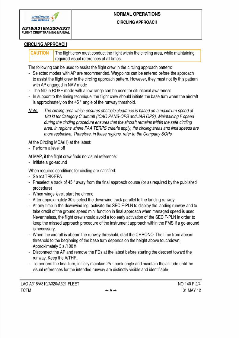
7/21/2019 FCTM date 21-Aug-14
http://slidepdf.com/reader/full/fctm-date-21-aug-14 192/393
A318/A319/A320/A321FLIGHT CREW TRAINING MANUAL
NORMAL OPERATIONS
CIRCLING APPROACH
LAO A318/A319/A320/A321 FLEET NO-140 P 2/4
FCTM ← A → 31 MAY 12
CIRCLING APPROACH
CAUTION The flight crew must conduct the flight within the circling area, while maintainingrequired visual references at all times.
The following can be used to assist the flight crew in the circling approach pattern:‐ Selected modes with AP are recommended. Waypoints can be entered before the approach
to assist the flight crew in the circling approach pattern. However, they must not fly this patternwith AP engaged in NAV mode
‐ The ND in ROSE mode with a low range can be used for situational awareness
‐ In support to the timing technique, the flight crew should initiate the base turn when the aircraftis approximately on the 45 ° angle of the runway threshold.
Note: The circling area which ensures obstacle clearance is based on a maximum speed of
180 kt for Category C aircraft (ICAO PANS-OPS and JAR OPS). Maintaining F speed during the circling procedure ensures that the aircraft remains within the safe circling
area. In regions where FAA TERPS criteria apply, the circling areas and limit speeds are more restrictive. Therefore, in these regions, refer to the Company SOPs.
At the Circling MDA(H) at the latest:‐ Perform a level off
At MAP, if the flight crew finds no visual reference:
‐ Initiate a go-around
When required conditions for circling are satisfied:
‐ Select TRK-FPA‐ Preselect a track of 45 ° away from the final approach course (or as required by the published
procedure)
‐ When wings level, start the chrono‐ After approximately 30 s select the downwind track parallel to the landing runway
‐ At any time in the downwind leg, activate the SEC F-PLN to display the landing runway and to
take credit of the ground speed mini function in final approach when managed speed is used.Nevertheless, the flight crew should avoid a too early activation of the SEC F-PLN in order to
keep the missed approach procedure of the instrument approach within the FMS if a go-aroundis necessary.
‐ When the aircraft is abeam the runway threshold, start the CHRONO. The time from abeamthreshold to the beginning of the base turn depends on the height above touchdown:Approximately 3 s /100 ft.
‐ Disconnect the AP and remove the FDs at the latest before starting the descent toward therunway. Keep the A/THR.
‐ To perform the final turn, initially maintain 25 ° bank angle and maintain the altitude until thevisual references for the intended runway are distinctly visible and identifiable

7/21/2019 FCTM date 21-Aug-14
http://slidepdf.com/reader/full/fctm-date-21-aug-14 193/393
A318/A319/A320/A321FLIGHT CREW TRAINING MANUAL
NORMAL OPERATIONS
CIRCLING APPROACH
LAO A318/A319/A320/A321 FLEET NO-140 P 3/4
FCTM ← A 31 MAY 12
‐ Set the landing configuration when appropriate, but ensure early stabilization in final
‐ When the aircraft is fully configured for landing, complete LANDING checklist.
If, at any time during the circling procedure, the required visual references are lost, the mainobjective is to climb and to leave the circling area into the missed approach of the initial instrument
approach, while remaining within the obstacle-free area, unless otherwise specified.When the SEC F-PLN is activated, the go-around procedure in the FMS is associated with the
landing runway, and not with the instrument approach. Therefore, if visual references are lostduring the circling approach, the flight crew should fly the go-around using selected guidance,following the pre-briefed missed approach procedure, unless otherwise specified.
For circling approach with one engine inoperative (A330 aircraft), refer to FCTM AO-020 Circling
One Engine Inoperative.

7/21/2019 FCTM date 21-Aug-14
http://slidepdf.com/reader/full/fctm-date-21-aug-14 194/393
A318/A319/A320/A321FLIGHT CREW TRAINING MANUAL
NORMAL OPERATIONS
CIRCLING APPROACH
LAO A318/A319/A320/A321 FLEET NO-140 P 4/4
FCTM B 31 MAY 12
CIRCLING APPROACH PATTERN
Ident.: NO-140-00014212.0001001 / 17 NOV 11Applicable to: ALL

7/21/2019 FCTM date 21-Aug-14
http://slidepdf.com/reader/full/fctm-date-21-aug-14 195/393
A318/A319/A320/A321FLIGHT CREW TRAINING MANUAL
NORMAL OPERATIONS
VISUAL APPROACH
LAO A318/A319/A320/A321 FLEET NO-150 P 1/4
FCTM A to B → 27 AUG 13
INITIAL APPROACH
Ident.: NO-150-00005560.0002001 / 09 JUN 10Applicable to: ALL
The flight crew must keep in mind that the pattern is flown visually. However, the cross track error on
ND is a good cue of the aircraft lateral position versus the runway centerline. This indication can beobtained when performing a DIR TO radial inbound on the last available waypoint, positionned on theextended runway centerline.
The crew will aim to get the following configuration on commencement of the downwind leg:• Both AP and FDs will be selected off• BIRD ON
• A/THR confirmed active in speed mode, i.e. SPEED on the FMA.• Managed speed will be used to enable the "GS mini" function
• The downwind track will be selected on the FCU to assist in downwind tracking.• The downwind track altitude will be set on FCU
INTERMEDIATE/FINAL APPROACH
Ident.: NO-150-00005562.0001001 / 29 MAY 13
Applicable to: ALL
Assuming a 1 500 ft AAL circuit, the base turn should be commenced 45 s after passing abeam thedownwind threshold (3 s/100 ft +/- 1 s/1 kt of head/downwind).The final turn onto the runway centreline will be commenced with 20 ° angle of bank. Initially the rate
of descent should be 400 ft/min, increasing to 700 ft/min when established on the correct descentpath
The pilot will aim to be configured for landing at VAPP by 500 ft AAL, at the latest. If not stabilised, ago-around must be carried out.

7/21/2019 FCTM date 21-Aug-14
http://slidepdf.com/reader/full/fctm-date-21-aug-14 196/393
A318/A319/A320/A321FLIGHT CREW TRAINING MANUAL
NORMAL OPERATIONS
VISUAL APPROACH
LAO A318/A319/A320/A321 FLEET NO-150 P 2/4
FCTM ← B → 27 AUG 13
visual approach

7/21/2019 FCTM date 21-Aug-14
http://slidepdf.com/reader/full/fctm-date-21-aug-14 197/393
A318/A319/A320/A321FLIGHT CREW TRAINING MANUAL
NORMAL OPERATIONS
VISUAL APPROACH
LAO A318/A319/A320/A321 FLEET NO-150 P 3/4
FCTM ← B → 27 AUG 13

7/21/2019 FCTM date 21-Aug-14
http://slidepdf.com/reader/full/fctm-date-21-aug-14 198/393
A318/A319/A320/A321FLIGHT CREW TRAINING MANUAL
NORMAL OPERATIONS
VISUAL APPROACH
LAO A318/A319/A320/A321 FLEET NO-150 P 4/4
FCTM ← B 27 AUG 13

7/21/2019 FCTM date 21-Aug-14
http://slidepdf.com/reader/full/fctm-date-21-aug-14 199/393
A318/A319/A320/A321FLIGHT CREW TRAINING MANUAL
NORMAL OPERATIONS
PRECISION APPROACH
LAO A318/A319/A320/A321 FLEET NO-160 P 1/8
FCTM A to B → 15 FEB 13
GENERAL
Ident.: NO-160-00005563.0001001 / 23 MAY 08Applicable to: ALL
CAT II and CAT III approaches are flown to very low DH (or without DH) with very low RVR. The
guidance of the aircraft on the ILS beam and the guidance of the aircraft speed must be consistentlyof high performance and accurate so that an automatic landing and roll out can be performed in goodconditions and, the acquisition of visual cues is achieved and the aircraft properly stabilized. Hence,
• The automatic landing is required in CAT III operations including roll out in CAT IIIB.• The automatic landing is the preferred landing technique in CAT II conditions
• Any failures of the automated systems shall not significantly affect the aircraft automatic landing
system performance• The crew procedures and task sharing allow to rapidly detect any anomaly and thus lead to the
right decision
DEFINITION
Ident.: NO-160-00005564.0001001 / 25 JUN 08
Applicable to: ALL
DECISION HEIGHT
The Decision Height (DH) is the wheel height above the runway elevation by which a go aroundmust be initiated unless appropriate visual reference has been established and the aircraft positionand the approach path have been assessed as satisfactory to continue the automatic approach
and landing safely. The DH is based on RA.
ALERT HEIGHT
The Alert Height (AH) is the height above the runway, based on the characteristics of the
aeroplane and its fail-operational automatic landing system, above which a CATIII approach wouldbe discontinued and a missed approach initiated if a failure occurred in one of the redundant partsof the automatic landing system, or in the relevant ground equipment.
In others AH definition, it is generally stated that if a failure affecting the fail-operational criteriaoccurs below the AH, it would be ignored and the approach continued (except if AUTOLAND
warning is triggered). The AH concept is relevant when CAT 3 DUAL is displayed on FMA.On single aisle Airbus family, the AH =100 ft.
CAT 3 SINGLE
CAT 3 SINGLE is announced when the airborne systems are fail passive which means that a
single failure will lead to the AP disconnection without any significant out of trim condition ordeviation of the flight path or attitude. Manual flight is then required. This minimum DH is 50 ft.

7/21/2019 FCTM date 21-Aug-14
http://slidepdf.com/reader/full/fctm-date-21-aug-14 200/393
A318/A319/A320/A321FLIGHT CREW TRAINING MANUAL
NORMAL OPERATIONS
PRECISION APPROACH
LAO A318/A319/A320/A321 FLEET NO-160 P 2/8
FCTM ← B to C 15 FEB 13
CAT 3 DUAL
CAT 3 DUAL is announced when the airborne systems are fail-operational. In case of a singlefailure, the AP will continue to guide the aircraft on the flight path and the automatic landingsystem will operate as a fail-passive system. In the event of a failure below the AH, the approach,
flare and landing can be completed by the remaining part of the automatic system. In that case, nocapability degradation is indicated. Such a redundancy allows CAT III operations with or without
DH.
CAT II OR CAT III APPROACHES
ICAO FAA JAA
DH 100 ft ≤ DH < 200 ft 100 ft ≤ DH < 200 ft 100 ft ≤ DH < 200 ftCAT II
RVR RVR ≥ 350 mRVR ≥ 1 200 ft
350 m ≤ RVR < 800 m1 200 ft ≤ RVR < 2 400 ft
RVR ≥ 300 mRVR ≥ 1 000 ft
DH No DH or DH < 100 ft No DH or DH < 100 ft DH < 100 ft (1)CAT IIIA
RVR RVR ≥ 200 mRVR ≥ 700 ft
RVR ≥ 200 mRVR ≥ 700 ft
RVR ≥ 200 mRVR ≥ 700 ft
DH No DH or DH < 50 ft No DH or DH < 50 ft No DH or DH < 50 ftCAT IIIB
RVR 50 m ≤ RVR < 200 m150 ft ≤ RVR < 700 ft
50 m ≤ RVR < 200 m150 ft ≤ RVR < 700 ft
75 m ≤ RVR < 200 m250 ft ≤ RVR < 700 ft
(1) DH ≥ 50 ft if fail passive
FLIGHT PREPARATION
Ident.: NO-160-00005566.0001001 / 26 MAR 08Applicable to: ALL
In addition to the normal flight preparation, the following preparation must be performed when CAT II
or CAT III approach is planned:• Ensure that destination airport meets CAT II or CAT III requirements
• Check aircraft required equipment for CAT II or CAT III in QRH• Check that crew qualification is current
• Consider extra fuel for possible approach delay• Consider weather at alternate

7/21/2019 FCTM date 21-Aug-14
http://slidepdf.com/reader/full/fctm-date-21-aug-14 201/393
A318/A319/A320/A321FLIGHT CREW TRAINING MANUAL
NORMAL OPERATIONS
PRECISION APPROACH
LAO A318/A319/A320/A321 FLEET NO-160 P 3/8
FCTM D → 15 FEB 13
APPROACH PREPARATION
Ident.: NO-160-00005567.0001001 / 08 FEB 13Applicable to: ALL
LIMITATIONS
• The crew will check that tower wind remains within the limit for CAT II or CAT III approaches
(Refer to FCOM/LIM-22-20 Maximum Wind Conditions for Cat II or Cat III Automatic Approach Landing and Roll Out )
• The autoland maximum altitude must be observed.
AIRCRAFT CAPABILITY
The failures that may affect the aircraft's CAT II or CAT III capability are listed in the QRH. Most ofthese failures are monitored by the FMGS and the landing capability will be displayed on the FMA
once the APPR pb is pressed, i.e. CAT II, CAT III SINGLE, CAT III DUAL. However, there area number of failures which affect the aircraft's landing capability which are not monitored by theFMGS and, consequently, not reflected on the FMA. It is very important, therefore, that the crew
refer to the QRH to establish the actual landing capability if some equipment are listed inoperative.
AIRPORT FACILITIES
The airport authorities are responsible for establishing and maintaining the equipment required
for CAT II/III approach and landing. The airport authorities will activate the LVP procedures as theneed arises based on RVR. Prior to planning a CAT II/III approach, the crew must ensure that LVPare in force.
CREW QUALIFICATION
The captain must ensure that both crew members are qualified and that their qualification is
current for the planned approach.
SEATING POSITION
The crew must realise the importance of eye position during low visibility approaches and landing.
A too low seat position may greatly reduce the visual segment. When the eye reference position islower than intended, the visual segment is further reduced by the cut-off angle of the glareshieldor nose. As a rule of thumb, an incorrect seating position which reduces the cut-off angle by 1 °
reduces the visual segment by approximately 10 m (30 ft).
USE OF LANDING LIGHTS
The use of landing lights at night in low visibility can be detrimental to the acquisition of visualreference. Reflected lights from water droplets or snow may actually reduce visibility. The landing
lights would, therefore, not normally be used in CAT II/III weather conditions.
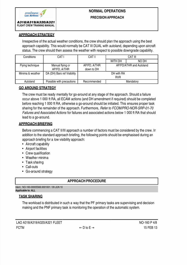
7/21/2019 FCTM date 21-Aug-14
http://slidepdf.com/reader/full/fctm-date-21-aug-14 202/393
A318/A319/A320/A321FLIGHT CREW TRAINING MANUAL
NORMAL OPERATIONS
PRECISION APPROACH
LAO A318/A319/A320/A321 FLEET NO-160 P 4/8
FCTM ← D to E → 15 FEB 13
APPROACH STRATEGY
Irrespective of the actual weather conditions, the crew should plan the approach using the bestapproach capability. This would normally be CAT III DUAL with autoland, depending upon aircraftstatus. The crew should then assess the weather with respect to possible downgrade capability.
CAT IIIConditions CAT I CAT II
WITH DH NO DH
Flying technique Manual flying or
AP/FD, A/THR
AP/FD, A/THR
down to DH
AP/FD/ATHR and Autoland
Minima & weather DA (DH) Baro ref Visibility DH with RARVR
Autoland Possible with precautions Recommended Mandatory
GO AROUND STRATEGY
The crew must be ready mentally for go-around at any stage of the approach. Should a failure
occur above 1 000 ft RA, all ECAM actions (and DH amendment if required) should be completedbefore reaching 1 000 ft RA, otherwise a go-around should be initiated. This ensures proper task
sharing for the remainder of the approach. Furthermore, Refer to FCOM/PRO-NOR-SRP-01-70 Failures and Associated Actions for failures and associated actions below 1 000 ft RA that should
lead to a go-around.
APPROACH BRIEFINGBefore commencing a CAT II/III approach a number of factors must be considered by the crew. Inaddition to the standard approach briefing, the following points should be emphasised during an
approach briefing for a low visibility approach:• Aircraft capability• Airport facilities
• Crew qualification• Weather minima
• Task sharing
• Call-outs• Go-around strategy
APPROACH PROCEDURE
Ident.: NO-160-00005568.0001001 / 09 JUN 10
Applicable to: ALL
TASK SHARING
The workload is distributed in such a way that the PF primary tasks are supervising and decision
making and the PNF primary task is monitoring the operation of the automatic system.

7/21/2019 FCTM date 21-Aug-14
http://slidepdf.com/reader/full/fctm-date-21-aug-14 203/393
A318/A319/A320/A321FLIGHT CREW TRAINING MANUAL
NORMAL OPERATIONS
PRECISION APPROACH
LAO A318/A319/A320/A321 FLEET NO-160 P 5/8
FCTM ← E → 15 FEB 13
The PF supervises the approach (trajectory, attitude, speed) and takes appropriate decision
in case of failure and at DH. Since the approach is flown with AP/FD/A-THR, the PF must becontinuously ready to take-over• If any AP hard over is experienced
• If a major failure occurs• If any doubt arises
The PF announces "LAND", when displayed on FMA.
The PNF is head down throughout the approach and landing. The PNF monitors:
• The FMA and calls all mode changes below 350 ft as required (i.e. after PF calls "LAND")• The Auto call out
• The aircraft trajectory or attitude exceedance• Any failures
The PNF should be go-around minded.
SOME SYSTEM PARTICULARS
• Below 700 ft RA, data coming from the FMS is frozen e.g. ILS tune inhibit.
• Below 400 ft RA, the FCU is frozen.• At 350 ft, LAND must be displayed on FMA. This ensures correct final approach guidance.
• Below 200 ft, the AUTOLAND red light illuminates if‐ Both APs trip off‐ Excessive beam deviation is sensed
‐ Localizer or glide slope transmitter or receiver fails‐ A RA discrepancy of at least 15 ft is sensed.
• Flare comes at or below 40 ft• THR IDLE comes at or below 30 ft• RETARD auto call out comes at 10 ft for autoland as an order. (Instead of 20 ft for manual
landing as an indication)
VISUAL REFERENCEApproaching the DH, the PF starts to look for visual references, progressively increasing externalscanning. It should be stressed that the DH is the lower limit of the decision zone. The captain
should come to this zone prepared for a go-around but with no pre-established judgement.

7/21/2019 FCTM date 21-Aug-14
http://slidepdf.com/reader/full/fctm-date-21-aug-14 204/393
A318/A319/A320/A321FLIGHT CREW TRAINING MANUAL
NORMAL OPERATIONS
PRECISION APPROACH
LAO A318/A319/A320/A321 FLEET NO-160 P 6/8
FCTM ← E → 15 FEB 13
Required conditions to continue
• With DHIn CAT II operations, the conditions required at DH to continue the approach are that the visualreferences should be appropriate to monitor the continued approach and landing and that the
flight path should be acceptable. If both these conditions are not satisfied, it is mandatory toinitiate a go-around. A 3 lights segment and a lateral light element is the minimum visual cue for
JAR OPS.In CAT III operations, the condition required at DH is that there should be visual referenceswhich confirm that the aircraft is over the touch down zone. Go-around is mandatory if the
visual references do not confirm this. A 3 lights segment is required by JAR OPS for fail passive
system and 1 centerline light segment for fail operational system.• Without DHThe decision to continue does not depend on visual references, even though a minimum RVRis specified. The decision depends only on the operational status of the aircraft and ground
equipment. If a failure occurs prior to reaching the AH, a go-around will be initiated. A go-aroundmust nevertheless be performed if AUTOLAND warning is triggered below AH. However, it is
good airmanship for the PF to acquire visual cues during flare and to monitor the roll out.
Loss of visual reference• With DH before touch down
If decision to continue has been made by DH and the visual references subsequently becomeinappropriate a go-around must be initiated.A late go-around may result in ground contact. If touch down occurs after TOGA is engaged,
the AP remains engaged in that mode and A/THR remains in TOGA. The ground spoilers andauto-brake are inhibited.
• With DH or without DH after touch downIf visual references are lost after touch down, a go-around should not be attempted. The roll-outshould be continued with AP in ROLL OUT mode down to taxi speed.
FLARE/LANDING/ROLL OUT
During the flare, decrab and roll-out, the PF will look outside to assess that the autoland is properlycarried out, considering the appropriate visual references.
For CAT II approaches, autoland is recommended. If manual landing is preferred, the PF willtake-over at 80 ft at the latest. This ensures a smooth transition for the manual landing.Select maximum reverse at main landing gear touch down.
The use of auto-brake is recommended as it ensures a symmetrical brake pressure application.However, the crew should be aware of possible dissymmetry in case of crosswind and wet
runways.

7/21/2019 FCTM date 21-Aug-14
http://slidepdf.com/reader/full/fctm-date-21-aug-14 205/393
A318/A319/A320/A321FLIGHT CREW TRAINING MANUAL
NORMAL OPERATIONS
PRECISION APPROACH
LAO A318/A319/A320/A321 FLEET NO-160 P 7/8
FCTM ← E to G 15 FEB 13
The PNF will use standard call out. Additionally, he will advise ATC when aircraft is properly
controlled (speed and lateral trajectory).
FAILURE AND ASSOCIATED ACTIONS
Ident.: NO-160-00005570.0001001 / 26 MAR 08Applicable to: ALL
As a general rule, if a failure occurs above 1 000 ft AGL, the approach may be continued, ECAM
actions completed, approach briefing update performed and a higher DH set if required.Below 1 000 ft (and down to AH in CAT3 DUAL), the occurrence of any failure implies a go-around
and a reassessment of the system capability. Another approach may be under taken according to the
new system capability. It has been considered that below 1 000 ft, not enough time is available forthe crew to perform the necessary switching, to check system configuration and limitation and brief
for minima.In CAT3 DUAL and below AH, as a general rule, a single failure does not necessitate a go-around. A
go-around is required if the AUTOLAND warning is triggered.
AUTOLAND IN CAT 1 OR BETTER WEATHER CONDITIONS
Ident.: NO-160-00005571.0001001 / 26 MAR 08Applicable to: ALL
The crew may wish to practice automatic landings in CAT I or better weather conditions for trainingpurposes. This type of approach should be carried out only with the airline authorization. The crewshould be aware that fluctuations of the LOC and/or GS might occur due to the fact that protection
of ILS sensitive areas, which applies during LVP, will not necessarily be in force. It is essential,therefore, that the PF is prepared to take over manually at any time during a practice approach androllout, should the performance of the AP become unsatisfactory.

7/21/2019 FCTM date 21-Aug-14
http://slidepdf.com/reader/full/fctm-date-21-aug-14 206/393
A318/A319/A320/A321FLIGHT CREW TRAINING MANUAL
NORMAL OPERATIONS
PRECISION APPROACH
Intentionally left blank
LAO A318/A319/A320/A321 FLEET NO-160 P 8/8
FCTM 15 FEB 13

7/21/2019 FCTM date 21-Aug-14
http://slidepdf.com/reader/full/fctm-date-21-aug-14 207/393

7/21/2019 FCTM date 21-Aug-14
http://slidepdf.com/reader/full/fctm-date-21-aug-14 208/393
A318/A319/A320/A321FLIGHT CREW TRAINING MANUAL
NORMAL OPERATIONS
LANDING
LAO A318/A319/A320/A321 FLEET NO-170 P 2/12
FCTM ← B 21 AUG 14
Use of PAPI/VASI/T.VASI
This technique will ensure that performance margins are not compromised and provide adequate
main gear clearance.

7/21/2019 FCTM date 21-Aug-14
http://slidepdf.com/reader/full/fctm-date-21-aug-14 209/393
A318/A319/A320/A321FLIGHT CREW TRAINING MANUAL
NORMAL OPERATIONS
LANDING
LAO A318/A319/A320/A321 FLEET NO-170 P 3/12
FCTM C → 21 AUG 14
FLARE
Ident.: NO-170-00005576.0001001 / 13 JAN 14Applicable to: ALL
PITCH CONTROL
When reaching 50 ft, auto-trim ceases and the pitch law is modified to flare law. Indeed, the
normal pitch law, which provides trajectory stability, is not the best adapted to the flare manoeuvre.The system memorizes the attitude at 50 ft, and that attitude becomes the initial reference for
pitch attitude control. As the aircraft descends through 30 ft, the system begins to reduce thepitch attitude to -2 °nose down over a period of 8 s. Consequently, the pilot will have to move thestick rearwards, so as to reproduce conventional aircraft aerodynamic characteristics. The flare
technique is thus very conventional.Prior to flare, avoid destabilization of the approach and steepening the slope at low heights in
attempts to target a shorter touchdown. If a normal touchdown point cannot be achieved or ifdestabilization occurs just prior to flare, a go-around (or rejected landing) should be performed.The PNF monitors the rate of descent and should call "SINK RATE " if the vertical speed is
excessive prior to the flare.From stabilized conditions, the flare height is about 30 ft.
This height varies due to the range of typical operational conditions that can directly influence therate of descent.
Compared to typical sea level flare heights for flat and adequate runway lengths, pilot need to beaware of factors that will require an earlier flare, in particular:
• High airport elevation.Increased altitude will result in higher ground speeds during approach with associated increase
in descent rates to maintain the approach slope.• Steeper approach slope (compared to nominal 3 °).
• Tailwind.Increased tailwind will result in higher ground speed during approach with associated increase
in descent rates to maintain the approach slope.
• Increasing runway slope.Increasing runway slope and/or rising terrain in front of the runway will affect the radio height
callouts down to over flying the threshold used by the flight crew to assess the height for thestart of flare possibly causing flare inputs to be late. The visual misperception of being high is
also likely.
Note that the cumulative effect of any of the above factors combined for one approach will requireeven more anticipation to perform an earlier flare.
If the flare is initiated too late then the pitch changes will not have sufficient time to allow thenecessary change to aircraft trajectory. Late, weak or released flare inputs increase the risk of ahard landing.

7/21/2019 FCTM date 21-Aug-14
http://slidepdf.com/reader/full/fctm-date-21-aug-14 210/393
A318/A319/A320/A321FLIGHT CREW TRAINING MANUAL
NORMAL OPERATIONS
LANDING
LAO A318/A319/A320/A321 FLEET NO-170 P 4/12
FCTM ← C 21 AUG 14
Avoid under flaring.
• The rate of descent must be controlled prior to the initiation of the flare (rate not increasing)• Start the flare with positive ( or "prompt") backpressure on the sidestick and holding as
necessary
• Avoid forward stick movement once Flare initiated (releasing back-pressure is acceptable)
At 20 ft, the "RETARD" auto call-out reminds the pilot to retard thrust levers. It is a reminder ratherthan an order. When best adapted, the pilot will rapidly retard all thrust levers: depending on the
conditions, the pilot will retard earlier or later. However, the pilot must ensure that all thrust leversare at IDLE detent at the latest at touchdown, to ensure ground spoilers extension at touchdown.In order to assess the rate of descent in the flare, and the aircraft position relative to the ground,
look well ahead of the aircraft. The typical pitch increment in the flare is approximately 4 °, whichleads to -1 ° flight path angle associated with a 10 kt speed decay in the manoeuvre. Do not allow
the aircraft to float or do not attempt to extend the flare by increasing pitch attitude in an attemptto achieve a perfectly smooth touchdown. A prolonged float will increase both the landing distance
and the risk of tail strike.
LATERAL AND DIRECTIONAL CONTROL
FINAL APPROACH
In crosswind conditions, a crabbed-approach wings-level should be flown with the aircraft
(cockpit) positioned on the extended runway centerline until the flare.
FLARE
The objectives of the lateral and directional control of the aircraft during the flare are:
• To land on the centerline and,• to minimize the lateral loads on the main landing gear.
The recommended de-crab technique is to use all of the following:
• The rudder to align the aircraft with the runway heading during the flare.• The roll control, if needed, to maintain the aircraft on the runway centerline. Any tendency to
drift downwind should be counteracted by an appropriate lateral (roll) input on the sidestick.
In the case of strong crosswind, in the de-crab phase, the PF should be prepared to addsmall bank angle into the wind in order to maintain the aircraft on the runway centerline. The
aircraft may be landed with a partial de-crab (residual crab angle up to about 5 °) to prevent anexcessive bank. This technique prevents wingtip/sharklet (or engine nacelle) strike caused byan excessive bank angle.
As a consequence, this may result in touching down with some bank angle into the wind (hencewith the upwind landing gear first).

7/21/2019 FCTM date 21-Aug-14
http://slidepdf.com/reader/full/fctm-date-21-aug-14 211/393

7/21/2019 FCTM date 21-Aug-14
http://slidepdf.com/reader/full/fctm-date-21-aug-14 212/393
A318/A319/A320/A321FLIGHT CREW TRAINING MANUAL
NORMAL OPERATIONS
LANDING
LAO A318/A319/A320/A321 FLEET NO-170 P 6/12
FCTM ← F to G → 21 AUG 14
At lower speeds, the directional control of the aircraft is more problematic, more specifically
on wet and contaminated runways. Differential braking is to be used if necessary. On wet andcontaminated runways, the same braking effect may be reached with full or half deflection of the
pedals; additionally the anti skid system releases the brake pressure on both sides very earlywhen the pilot presses on the pedals. Thus if differential braking is to be used, the crew will totallyrelease the pedal on the opposite side to the expected turn direction.
BRAKING
Ident.: NO-170-00005584.0003001 / 19 MAY 14
Applicable to: ALL
Once on the ground, the importance of the timely use of all means of stopping the aircraft cannot beoveremphasised. Three systems are involved in braking once the aircraft is on the ground:
• The ground spoilers• The thrust reversers
• The wheel brakes
THE GROUND SPOILERS
When the aircraft touches down with at least one main landing gear and when at least one thrustlever is in the reverse sector, the ground spoilers partially automatically deploy to ensure that the
aircraft is properly sit down on ground. Then, the ground spoilers automatically fully deploy. This isthe partial lift dumping function.The ground spoilers contribute to aircraft deceleration by increasing aerodynamic drag at high
speed. Wheel braking efficiency is improved due to the increased load on the wheels. Additionally,the ground spoiler extension signal is used for auto-brake activation.
REVERSE THRUST EFFICIENCY
Thrust reversers are more efficient at high speeds: The flight crew must select reverse thrustimmediately after main landing gear touchdown.
Below 70 kt, thrust reversers efficiency rapidly decreases. Below 60 kt with REV MAX selected,engine stall may occur. Therefore, it is recommended to reduce the reverse thrust to REV IDLE at70 kt, and keep REV IDLE until taxi speed. However in an emergency case, the flight crew must
keep REV MAX until full-stop of the aircraft.At taxi speed, and not above, stow the thrust reversers before leaving the runway, in order to avoidforeign object ingestion.
REVERSE THRUST SELECTION
The selection of REV MAX is the standard practice for landing.

7/21/2019 FCTM date 21-Aug-14
http://slidepdf.com/reader/full/fctm-date-21-aug-14 213/393
A318/A319/A320/A321FLIGHT CREW TRAINING MANUAL
NORMAL OPERATIONS
LANDING
LAO A318/A319/A320/A321 FLEET NO-170 P 7/12
FCTM ← G → 21 AUG 14
LANDING ON DRY RUNWAYS
On DRY runways, the flight crew may select REV IDLE.LANDING ON WET RUNWAYS
On WET runways, the flight crew may select REV IDLE, if all the conditions described in theSOP DESCENT PREPARATION (Refer to FCOM/SOP DESCENT PREPARATION ) aresatisfied.
LANDING ON CONTAMINATED RUNWAYS
On contaminated runways, the flight crew must select REV MAX.
REMINDER ON LANDING DISTANCE COMPUTATION AT DISPATCH FOR DRY AND WETRUNWAYS
DEFINITIONS
ALD : The Actual Landing Distance is the distance used on a dry runway from
the crossing of the runway threshold at 50 ft until full-stop of the aircraft,using maximum manual braking. No reverse thrust is considered for
the calculation of the ALD. The ALD is demonstrated during flight testcampaign for certification purpose.
RLD dry : The Required Landing Distance on a dry runway is a factored ALD. Thefactor is 1.67. (RLD dry = ALD x 1.67)
RLD wet : The Required Landing Distance on a wet runway is a factored ALD. The
factor is 1.92 (RLD wet = RLD dry x 1.15)
DISPATCH CONDITIONS
For landing distance computation at dispatch, the airline uses the RLD.Landing distances computed at dispatch for wet runways provide only reduced margins in
comparison with landing distances achievable in operations with the use of REV IDLE. Sufficient
margins are restored when the flight crew uses REV MAX.The runway slope is not considered for the landing distance computation at dispatch.
On a destination airport with multiple runways, the landing distance computation at dispatchmay be performed on the longest landing runway with no wind.
The expected landing runway may be used for the landing distance computation at dispatchwith forecast wind at landing. If the wind condition changes at landing, the flight crew must
perform a new landing distance computation.
LANDING WITH REV IDLE ON WET RUNWAYS
The landing distance computation at dispatch (RLD) does not consider REV IDLE operation.Therefore, it is necessary to perform a computation to consider REV IDLE operation,

7/21/2019 FCTM date 21-Aug-14
http://slidepdf.com/reader/full/fctm-date-21-aug-14 214/393
A318/A319/A320/A321FLIGHT CREW TRAINING MANUAL
NORMAL OPERATIONS
LANDING
LAO A318/A319/A320/A321 FLEET NO-170 P 8/12
FCTM ← G → 21 AUG 14
as described in the SOP DESCENT PREPARATION (Refer to FCOM/SOP DESCENT
PREPARATION ). This may be done before the flight.At descent preparation, if the flight crew considers the use of REV IDLE on a wet runway, they
should be able to confirm a MEDIUM TO POOR landing distance computation with no reversecredit on the predicted landing runway.A MEDIUM TO POOR computation enables the flight crew to consider extreme situations where
a runway reported wet is worse than wet. If a runway reported wet is water contaminated, thebraking action is a function of the water depth. During active precipitation or shortly afterwards,
the water depth is variable, and therefore difficult to evaluate and to report accurately.Therefore on runways reported wet, the real friction coefficient may be significantly less thanexpected and/or aquaplaning may occur. When REV IDLE is used, the maximum possible
deceleration of the aircraft mainly depends on the runway friction coefficient.
WHEEL BRAKES
Wheel brakes contribute the most to aircraft deceleration on the ground. Many factors may affect
efficient braking such as load on the wheels, tire pressure, runway pavement characteristics andrunway contamination and braking technique. The only factor over which the pilot has any controlis the use of the correct braking technique, as discussed below.
ANTI-SKID
The anti-skid system adapts pilot applied brake pressure to runway conditions by sensing animpending skid condition and adjusting the brake pressure to each individual wheel as required.The anti-skid system maintains the skidding factor (slip ratio) close to the maximum friction
force point. This will provide the optimum deceleration with respect to the pilot input. Full pedalbraking with anti-skid provides a deceleration rate of 10 kt/sec.
BRAKES
The use of auto brake versus pedal braking should observe the following guidelines:
• The use of A/BRAKE is usually preferable because it minimizes the number of brakeapplications and thus reduces brake wear. Additionally, the A/BRAKE provides a symmetrical
brake pressure application which ensures an equal braking effect on both main landinggear wheels on wet or evenly contaminated runway. More particularly, the A/BRAKE is
recommended on short, wet, contaminated runway, in poor visibility conditions and in Autoland.
• The use of LO auto brake should be preferred on long and dry runways whereas the use of
MED auto brake should be preferred for short or contaminated runways.• On very short runways, the use of pedal braking is to be envisaged since the pilot may apply
full pedal braking with no delay after touch down.

7/21/2019 FCTM date 21-Aug-14
http://slidepdf.com/reader/full/fctm-date-21-aug-14 215/393
A318/A319/A320/A321FLIGHT CREW TRAINING MANUAL
NORMAL OPERATIONS
LANDING
LAO A318/A319/A320/A321 FLEET NO-170 P 9/12
FCTM ← G → 21 AUG 14
• On very long runways, the use of pedal braking may be envisaged if the pilot anticipates that
braking will not be needed. To reduce brake wear, the number of brake application should belimited.
• In case of pedal braking, do not ride the brakes but apply pedal braking when required andmodulate the pressure without releasing. This minimizes brake wear.
The green DECEL light comes on when the actual deceleration is 80 % of the selected rate. For
example the DECEL light might not appear when the autobrake is selected on a contaminatedrunway, because the deceleration rate is not reached with the autobrake properly functioning.Whereas the DECEL light might appear with LO selected on a dry runway while only the
reversers achieve the selected deceleration rate without autobrake being actually activated. In
other words, the DECEL light is not an indicator of the autobrake operation as such, but that thedeceleration rate is reached.Since the auto brake system senses deceleration and modulates brake pressure accordingly,the timely application of MAX reverse thrust will reduce the actual operation of the brakes
themselves, thus the brake wear and temperature.Auto-brake does not relieve the pilot of the responsibility of achieving a safe stop within the
available runway length.
CROSS WIND CONDITIONS
The reverse thrust side force and crosswind component can combine to cause the aircraft to driftto the downwind side of the runway if the aircraft is allowed to weathercock into wind after landing.
Additionally, as the anti-skid system will be operating at maximum braking effectiveness, the maingear tire cornering forces available to counteract this drift will be reduced.
Braking Force and Cornering Force vs Antiskid
To correct back to the centreline, the pilot must reduce reverse thrust to reverse idle and releasethe brakes. This will minimise the reverse thrust side force component, without the requirement
to go through a full reverser actuating cycle, and provide the total tire cornering forces for
realignment with the runway centreline. Rudder and differential braking should be used, as

7/21/2019 FCTM date 21-Aug-14
http://slidepdf.com/reader/full/fctm-date-21-aug-14 216/393
A318/A319/A320/A321FLIGHT CREW TRAINING MANUAL
NORMAL OPERATIONS
LANDING
LAO A318/A319/A320/A321 FLEET NO-170 P 10/12
FCTM ← G to I → 21 AUG 14
required, to correct back to the runway centreline. When re-established on the runway centreline,
the pilot should re-apply braking and reverse thrust as required.
Directional Control During Crosswind Landing
CLEARANCE AT TOUCH DOWN
Ident.: NO-170-00005587.0003001 / 26 MAR 08
Applicable to: ALL
Geometry limit at touch down Pitch attitude at
VAPP(Vref +5 kt) (1)
Pitch attitude at touch down Clearance (2)
13.5 ° 3.3 ° 7.6 ° 5.9 °
(1) Flight path in approach: -3 ° (2) Clearance = geometry limit - pitch attitude at touch down
TAIL STRIKE AVOIDANCE
Ident.: NO-170-00005589.0001001 / 09 JUN 10
Applicable to: ALL
Although most of tail strikes are due to deviations from normal landing techniques, some areassociated with external conditions such as turbulence and wind gradient.

7/21/2019 FCTM date 21-Aug-14
http://slidepdf.com/reader/full/fctm-date-21-aug-14 217/393
A318/A319/A320/A321FLIGHT CREW TRAINING MANUAL
NORMAL OPERATIONS
LANDING
LAO A318/A319/A320/A321 FLEET NO-170 P 11/12
FCTM ← I → 21 AUG 14
DEVIATION FROM NORMAL TECHNIQUES
Deviations from normal landing techniques are the most common causes of tail strikes. The mainreasons for this are due to:• Allowing the speed to decrease well below VAPP before flare
Flying at too low speed means high angle of attack and high pitch attitude, thus reducing groundclearance. When reaching the flare height, the pilot will have to significantly increase the pitch
attitude to reduce the sink rate. This may cause the pitch to go beyond the critical angle.• Prolonged hold off for a smooth touch down
As the pitch increases, the pilot needs to focus further ahead to assess the aircraft's position
in relation to the ground. The attitude and distance relationship can lead to a pitch attitude
increase beyond the critical angle.• Too high flareA high flare can result in a combined decrease in airspeed and a long float. Since both lead toan increase in pitch attitude, the result is reduced tail clearance.
• Too high sink rate, just prior reaching the flare heightIn case of too high sink rate close to the ground, the pilot may attempt to avoid a firm touch
down by commanding a high pitch rate. This action will significantly increase the pitch attitudeand, as the resulting lift increase may be insufficient to significantly reduce the sink rate, thehigh pitch rate may be difficult to control after touch down, particularly in case of bounce.
• Bouncing at touch downIn case of bouncing at touch down, the pilot may be tempted to increase the pitch attitude to
ensure a smooth second touch down. If the bounce results from a firm touch down, associatedwith high pitch rate, it is important to control the pitch so that it does not further increase beyond
the critical angle.
APPROACH AND LANDING TECHNIQUES
A stabilized approach is essential for achieving successful landings. It is imperative that the flareheight be reached at the appropriate airspeed and flight path angle. The A/THR and FPV are
effective aids to the pilot.
VAPP should be determined with the wind corrections (provided in FCOM/QRH) by using theFMGS functions. As a reminder, when the aircraft is close to the ground, the wind intensity
tends to decrease and the wind direction to turn (direction in degrees decreasing in the northernlatitudes). Both effects may reduce the head wind component close to the ground and the wind
correction to VAPP is there to compensate for this effect.When the aircraft is close to the ground, high sink rate should be avoided, even in an attempt to
maintain a close tracking of the glideslope. Priority should be given to the attitude and sink rate. Ifa normal touchdown distance is not possible, a go-around should be performed.If the aircraft has reached the flare height at VAPP, with a stabilized flight path angle, the normal
SOP landing technique will lead to the right touchdown attitude and airspeed.

7/21/2019 FCTM date 21-Aug-14
http://slidepdf.com/reader/full/fctm-date-21-aug-14 218/393

7/21/2019 FCTM date 21-Aug-14
http://slidepdf.com/reader/full/fctm-date-21-aug-14 219/393
A318/A319/A320/A321FLIGHT CREW TRAINING MANUAL
NORMAL OPERATIONS
GO AROUND
LAO A318/A319/A320/A321 FLEET NO-180 P 1/4
FCTM A to B → 06 MAR 14
PREFACE
Ident.: NO-180-00005592.0001001 / 26 MAR 08Applicable to: ALL
Failure to recognize the need for and to execute a go-around, when required, is a major cause of
approach and landing accidents. Because a go-around is an infrequent occurrence, it is important tobe "go-around minded". The decision to go-around should not be delayed, as an early go-around issafer than a last minute one at lower altitude.
CONSIDERATION ABOUT GO-AROUND
Applicable to: ALL
Ident.: NO-180-A-00005593.0001001 / 08 NOV 13
DECISION MAKING
A go-around must be considered if:
• There is a loss or a doubt about situation awareness• If there is a malfunction which jeopardizes the safe completion of the approach e.g. major
navigation problem• ATC changes the final approach clearance resulting in rushed action from the crew or
potentially unstable approach
• The approach is unstable in speed, altitude, and flight path in such a way that stability will not beobtained by 1 000 ft IMC or 500 ft VMC.
• Any GPWS, TCAS or windshears alert occur• Adequate visual references are not obtained at minima or lost below minima.
Ident.: NO-180-A-00015224.0001001 / 22 OCT 13
GO-AROUND NEAR THE GROUND
If the PF initiates a go-around, the flight crew must complete the go-around maneuver. The PFmust not initiate a go-around after the selection of the thrust reversers.
If the flight crew performs a go-around near the ground, they should take into account thefollowing:‐ The PF should avoid excessive rotation rate, in order to prevent a tailstrike
‐ A temporary landing gear contact with the runway is acceptable. For more information Refer to NO-170 TAIL STRIKE AVOIDANCE
‐ In the case of bounce, the flight crew must consider delaying flap retraction‐ The PF should order landing gear retraction when the aircraft reaches and maintains positive
climb with no possibility of subsequent touchdown.

7/21/2019 FCTM date 21-Aug-14
http://slidepdf.com/reader/full/fctm-date-21-aug-14 220/393
A318/A319/A320/A321FLIGHT CREW TRAINING MANUAL
NORMAL OPERATIONS
GO AROUND
LAO A318/A319/A320/A321 FLEET NO-180 P 2/4
FCTM ← B to D → 06 MAR 14
Note: If the aircraft is on the runway and in FULL configuration when the PF applies TOGA
thrust, a CONFIG FLAPS NOT IN T.O CONFIG ECAM alert is triggered. The flight crew should disregard this alert.
AP/FD GO-AROUND PHASE ACTIVATION
Ident.: NO-180-00005594.0003001 / 03 DEC 13
Applicable to: ALL
When the thrust levers are set to the TOGA detent, and provided the real slats/flaps configuration is
different from clean configuration, all of the following occur:
‐ If the autopilot or the flight director is in use, SRS and GA TRK(NAV) modes engage.‐ If the autopilot and both flight directors are off, the PF will maintain 15 ° of pitch.
‐ The GA phase activates on the FMS:
‐ The missed approach becomes the active F-PLN‐ At the end of the missed approach procedure, the FMS strings the previous flown approach in
the active F-PLN.
‐ If not previously engaged, the FD automatically engages with the HDG/VS reference on the FCU.For the go-around, the appropriate flight reference is the attitude, because go-around is a dynamic
maneuver
‐ If extended, the speed brakes automatically retract.
If TOGA thrust is not desired during go-around for any reason, e.g. an early go-around ordered by
ATC, it is essential that the thrust levers are set momentarily but without delay, to the TOGA detent(i.e. the full forward thrust levers position), in order to ensure proper activation of the SRS GA andthe Go-Around phase (i.e. guidance modes and FMS flight phase). Then, the flight crew should set
the thrust lever to CL detent to take advantage of the A/THR (the A/THR follows a speed target).
If the thrust levers are not correctly set to the TOGA detent, the following occur:‐ The AP/FD remain engaged in approach or landing mode (e.g. G/S, LOC, LAND, FLARE on FMA)
‐ The FMS does not engage the GA phase, and remains in APPR phase.
GO-AROUND PHASE
Ident.: NO-180-00005595.0002001 / 20 MAY 09
Applicable to: ALL
The SRS mode guides the aircraft with the highest speed of VAPP or IAS at time of TOGA selection
(limited to maximum of VLS +25 with all engines operative or VLS +15 with one engine inoperativewith FMS 2) until the acceleration altitude where the target speed increases to green dot.
Some FMS misbehaviour may prevent this automatic target speed increase. Should this occur,
pulling the FCU ALT knob for OP CLB manually disengages SRS mode and allows the target speed

7/21/2019 FCTM date 21-Aug-14
http://slidepdf.com/reader/full/fctm-date-21-aug-14 221/393
A318/A319/A320/A321FLIGHT CREW TRAINING MANUAL
NORMAL OPERATIONS
GO AROUND
LAO A318/A319/A320/A321 FLEET NO-180 P 3/4
FCTM ← D to F → 06 MAR 14
to increase to green dot. It should be noted however, that the target speed increases to green dot
speed as soon as ALT* mode engages when approaching the FCU clearance altitude.The GA TRK mode guides the aircraft on the track memorised at the time of TOGA selection. The
missed approach route becomes the ACTIVE F-PLN provided the waypoints have been correctlysequenced on the approach. Pushing for NAV enables the missed approach F-PLN to be followed.Above the go-around acceleration altitude, or when the flight crew engages another vertical mode
(CLB, OP CLB), the target speed is green dot.
ENGINES ACCELERATION
Ident.: NO-180-00005596.0001001 / 20 DEC 13
Applicable to: ALL
When the pilot sets TOGA thrust for go-around, it takes some time for the engines to spool up due to
the acceleration capability of the high by pass ratio engines. Therefore, the pilot must be aware thatthe aircraft will initially lose some altitude. This altitude loss will be greater if initial thrust is close to
idle and/or the aircraft speed is lower than VAPP.
Altitude Loss Following a Go-Around
LEAVING THE GO-AROUND PHASE
Ident.: NO-180-00005597.0001001 / 26 MAR 08
Applicable to: ALL
The purpose of leaving the go-around phase is to obtain the proper target speed and properpredictions depending upon the strategy chosen by the crew. During the missed approach, the crew
will elect either of the following strategies:• Fly a second approach• Carry out a diversion

7/21/2019 FCTM date 21-Aug-14
http://slidepdf.com/reader/full/fctm-date-21-aug-14 222/393
A318/A319/A320/A321FLIGHT CREW TRAINING MANUAL
NORMAL OPERATIONS
GO AROUND
LAO A318/A319/A320/A321 FLEET NO-180 P 4/4
FCTM ← F 06 MAR 14
SECOND APPROACH
If a second approach is to be flown, the crew will activate the approach phase in the MCDU PERFGO-AROUND page. The FMS switches to Approach phase and the target speed moves accordingto the flaps lever setting, e.g. green dot for Flaps 0.
The crew will ensure proper waypoint sequencing during the second approach in order to have themissed approach route available, should a further go-around be required.
DIVERSION
Once the aircraft path is established and clearance has been obtained, the crew will modify the
FMGS to allow the FMGS switching from go-around phase to climb phase:• If the crew has prepared the ALTN FPLN in the active F-PLN, a lateral revision at the TO WPT
is required to access the ENABLE ALTN prompt. On selecting the ENABLE ALTN prompt, thelateral mode reverts to HDG if previously in NAV. The aircraft will be flown towards the nextwaypoint using HDG or NAV via a DIR TO entry.
• If the crew has prepared the ALTN FPLN in the SEC F-PLN, the SEC F-PLN will be activated,and a DIR TO performed as required. AP/FD must be in HDG mode for the ACTIVATE SEC
F-PLN prompt to be displayed.• If the crew has not prepared the ALTN FPLN, a selected climb will be initiated. Once
established in climb and clear of terrain, the crew will make a lateral revision at any waypoint to
insert a NEW DEST. The route and a CRZ FL (on PROG page) can be updated as required.

7/21/2019 FCTM date 21-Aug-14
http://slidepdf.com/reader/full/fctm-date-21-aug-14 223/393
A318/A319/A320/A321FLIGHT CREW TRAINING MANUAL
NORMAL OPERATIONS
TAXI IN
LAO A318/A319/A320/A321 FLEET NO-190 P 1/4
FCTM A to C 21 AUG 14
BRAKE FANS
Ident.: NO-190-00005601.0001001 / 21 APR 08Applicable to: ALL
The use of brake fans could increase oxidation of the brake surface hot spots if brakes are notthermally equalized, leading to the rapid degradation of the brakes. For this reason, selection ofbrake fans should be delayed until approximately 5 min after touchdown or just prior to stoppingat the gate (whichever occurs first). Selecting brake fans before reaching the gate allows avoidingblowing carbon brake dust on ground personal.
BRAKE TEMPERATURE
Ident.: NO-190-00005602.0001001 / 23 MAY 08Applicable to: ALL
If there is a significant difference in brake temperature between the wheels of the same gear, whenreaching the gate, this materializes a potential problem with brake and a maintenance action is duee.g. if one wheel reaches the limit temperature of 600 °C while all others wheels brakes indicate lessthan 450 °C, this indicates that there is a potential problem of brake binding or permanent brakeapplication on that wheel. Conversely, if one wheel brake is at or below 60 °C whereas the others arebeyond 210 °C, this indicates that there is a potential loss of braking on that wheel. Selecting brakefans before reaching the gate allows avoiding blowing carbon brake dust on ground personal.
If brake temperature is above 500 °C with fans OFF (350 °C fans ON ), use of the parkingbrake, unless operationally necessary, should be avoided to prevent brake damage.If one brake temperature exceeds 900 °C, a maintenance action is due.The MEL provides information regarding brake ground cooling time, both with and without brake fans .
ENGINES COOLING PERIOD
Ident.: NO-190-00005604.0001001 / 29 JUL 14Applicable to: ALL
1 Operate the engines at or near idle thrust for a cooling period (Refer to FCOM/PRO-NOR-SOP-22 Parking - ENG Master Switches ) before shutdown to thermally stabilize the engines. Idle reversethrust and normal taxi maneuvering thrust are not considered as high thrust operations.However, if operationally necessary, all engines may be shut down upon arrival at the gate,regardless of the time since landing.
Note: Routine cooldown times shorter than the recommended period before engine shutdown can cause engine degradation such as blade damage or oil coking.

7/21/2019 FCTM date 21-Aug-14
http://slidepdf.com/reader/full/fctm-date-21-aug-14 224/393
A318/A319/A320/A321FLIGHT CREW TRAINING MANUAL
NORMAL OPERATIONS
TAXI IN
LAO A318/A319/A320/A321 FLEET NO-190 P 2/4
FCTM D 21 AUG 14
TAXI WITH ONE ENGINE SHUTDOWN
Ident.: NO-190-00005605.0001001 / 26 MAR 08Applicable to: ALL
Refer to NO-040 TAXI WITH ONE ENGINE SHUTDOWN

7/21/2019 FCTM date 21-Aug-14
http://slidepdf.com/reader/full/fctm-date-21-aug-14 225/393
A318/A319/A320/A321FLIGHT CREW TRAINING MANUAL
NORMAL OPERATIONS
TAXI IN
LAO A318/A319/A320/A321 FLEET NO-190 P 3/4
FCTM E 21 AUG 14
AFTER LANDING FLOW PATTERN
Ident.: NO-190-00005606.0001001 / 20 DEC 13Applicable to: ALL
After Landing Flow Pattern

7/21/2019 FCTM date 21-Aug-14
http://slidepdf.com/reader/full/fctm-date-21-aug-14 226/393
7/21/2019 FCTM date 21-Aug-14
http://slidepdf.com/reader/full/fctm-date-21-aug-14 227/393
ABNORMAL OPERATIONS

7/21/2019 FCTM date 21-Aug-14
http://slidepdf.com/reader/full/fctm-date-21-aug-14 228/393

7/21/2019 FCTM date 21-Aug-14
http://slidepdf.com/reader/full/fctm-date-21-aug-14 229/393

7/21/2019 FCTM date 21-Aug-14
http://slidepdf.com/reader/full/fctm-date-21-aug-14 230/393
A318/A319/A320/A321FLIGHT CREW TRAINING MANUAL
ABNORMAL OPERATIONS
PRELIMINARY PAGES
TABLE OF CONTENTS
LAO A318/A319/A320/A321 FLEET AO-PLP-TOC P 2/2
FCTM 21 AUG 14
Continued from the previous page
AO-029 HydraulicHYDRAULIC GENERATION PARTICULARITIES...................................................................................................A
DUAL HYDRAULIC FAILURES...............................................................................................................................B
Remaining Systems ............................................................................................................................................... C
AO-032 LANDING GEARLDG WITH ABNORMAL L/G...................................................................................................................................A
Nose Wheel Steering Fault..................................................................................................................................... B
LOSS OF BRAKING................................................................................................................................................C
AO-034 NAVIGATIONADR/IRS FAULT......................................................................................................................................................A
UNRELIABLE AIRSPEED INDICATIONS............................................................................................................... B
"UNRELIABLE SPEED INDIC/ADR CHECK PROC" QRH PROCEDURE.............................................................C
DUAL RADIO ALTIMETER FAILURE.....................................................................................................................D
AO-070 Power Plant
AO-070-A All Engine FlameoutAll Engine Flameout................................................................................................................................................ A
AO-090 MiscellaneousCOCKPIT WINDSHIELD/WINDOW CRACKED......................................................................................................A
Emergency Descent.................................................................................................................................................B
OVERWEIGHT LANDING....................................................................................................................................... C
CREW INCAPACITATION.......................................................................................................................................D

7/21/2019 FCTM date 21-Aug-14
http://slidepdf.com/reader/full/fctm-date-21-aug-14 231/393
A318/A319/A320/A321FLIGHT CREW TRAINING MANUAL
ABNORMAL OPERATIONS
PRELIMINARY PAGES
SUMMARY OF HIGHLIGHTS
LAO A318/A319/A320/A321 FLEET AO-PLP-SOH P 1/2
FCTM 21 AUG 14
Localization
Title
Toc
Index
ID Reason
AO-PLP-TOCOPERATING TECHNIQUES
1 Documentation update: Deletion of the "00005614.0001001REJECTED TAKEOFF" documentary unit.
AO-020REJECTED TAKE-OFF
B 1 Documentation update: Addition of "REJECTED TAKE-OFF"documentary unit
AO-020ENGINE FAILURE AFTER V1
F 2 Improvement of technical wording. Addition of engine relight (if nodamage) consideration before STATUS review.
AO-020Exceeding VMO/MMO
N 3 Improved wording to provide more flexibility to the flight crew touse the most appropriate speed brakes lever position in order torecover from the overspeed situation.
Deletion of sentence related to fuel imbalance. Should a fuelimbalance occur, the flight crew should refer to the QRH FUELIMBALANCE procedure
AO-028FUEL LEAK A 1
Documentation update: Deletion of text.
AO-029Remaining Systems
C 1 Correction of typo error in table.

7/21/2019 FCTM date 21-Aug-14
http://slidepdf.com/reader/full/fctm-date-21-aug-14 232/393
A318/A319/A320/A321FLIGHT CREW TRAINING MANUAL
ABNORMAL OPERATIONS
PRELIMINARY PAGES
SUMMARY OF HIGHLIGHTS
Intentionally left blank
LAO A318/A319/A320/A321 FLEET AO-PLP-SOH P 2/2
FCTM 21 AUG 14

7/21/2019 FCTM date 21-Aug-14
http://slidepdf.com/reader/full/fctm-date-21-aug-14 233/393
A318/A319/A320/A321FLIGHT CREW TRAINING MANUAL
ABNORMAL OPERATIONS
GENERAL
LAO A318/A319/A320/A321 FLEET AO-010 P 1/2
FCTM A 31 MAY 12
PREFACE
Ident.: AO-010-00005607.0001001 / 26 MAR 08Applicable to: ALL
The ABNORMAL OPERATIONS chapter highlights techniques that will be used in some abnormal
and emergency operations. Some of the procedures discussed in this chapter are the result ofdouble or triple failures. Whilst it is very unlikely that any of these failures will be encountered, itis useful to have a background understanding of the effect that they have on the handling and
management of the aircraft. In all cases, the ECAM should be handled as described in FCTM (Refer
to OP-040 PURPOSE OF THE ECAM ).

7/21/2019 FCTM date 21-Aug-14
http://slidepdf.com/reader/full/fctm-date-21-aug-14 234/393
A318/A319/A320/A321FLIGHT CREW TRAINING MANUAL
ABNORMAL OPERATIONS
GENERAL
Intentionally left blank
LAO A318/A319/A320/A321 FLEET AO-010 P 2/2
FCTM 31 MAY 12

7/21/2019 FCTM date 21-Aug-14
http://slidepdf.com/reader/full/fctm-date-21-aug-14 235/393
A318/A319/A320/A321FLIGHT CREW TRAINING MANUAL
ABNORMAL OPERATIONS
OPERATING TECHNIQUES
LAO A318/A319/A320/A321 FLEET AO-020 P 1/24
FCTM A to B → 21 AUG 14
LOW SPEED ENGINE FAILURE
Ident.: AO-020-00005612.0001001 / 27 JUN 12Applicable to: ALL
If an engine failure occurs at low speed, the resultant yaw may be significant, leading to rapiddisplacement from the runway centreline.
To regain or maintain directional control on the runway, it is necessary:‐ To immediately reduce both thrust levers to IDLE, which will reduce the thrust asymmetry caused
by the failed engine‐ To select both reversers irrespective of which engine has failed‐ To use rudder pedal for directional control, supplemented by symmetrical or differential braking if
needed.
The steering hand-wheels may be used when taxi is reached.
Note: 1. If rudder pedal input and differential braking are needed, apply both on the same side 2. Below 72 kts, the ground spoilers will not deploy and the auto brake will not activate.
REJECTED TAKE-OFF
1 Ident.: AO-020-00005614.0002001 / 01 APR 14Applicable to: ALL
FACTORS AFFECTING RTO
Experience has shown that a rejected takeoff can be hazardous, even if correct procedures arefollowed. Some factors that can detract from a successful rejected takeoff are as follows:• Tire damage• Brakes worn or not working correctly• Error in gross weight determination• Incorrect performance calculations• Incorrect runway line-up technique• Initial brake temperature• Delay in initiating the stopping procedure• Runway friction coefficient lower than expected
Thorough pre-flight preparation and a conscientious exterior inspection can eliminate the effect ofsome of these factors.During the taxi-out, a review of the takeoff briefing is required. During this briefing, the crew shouldconfirm that the computed takeoff data reflects the actual takeoff conditions e.g. wind and runwaycondition. Any changes to the planned conditions require the crew to re-calculate the takeoff
data. In this case, the crew should not be pressurised into accepting a takeoff clearance before

7/21/2019 FCTM date 21-Aug-14
http://slidepdf.com/reader/full/fctm-date-21-aug-14 236/393

7/21/2019 FCTM date 21-Aug-14
http://slidepdf.com/reader/full/fctm-date-21-aug-14 237/393
A318/A319/A320/A321FLIGHT CREW TRAINING MANUAL
ABNORMAL OPERATIONS
OPERATING TECHNIQUES
LAO A318/A319/A320/A321 FLEET AO-020 P 3/24
FCTM ← B → 21 AUG 14
(1): Announcing the deceleration means that the deceleration is felt by the crew, and confirmedby the Vc trend on the PFD. The deceleration may also be confirmed by the DECEL light (if theautobrake is on). However, this light only comes on when the actual deceleration is 80 % of theselected rate, it is not an indicator of the proper autobrake operation. For instance, the DECELlight might not appear on a contaminated runway, with the autobrake working properly, due to theeffect of the antiskid.If the takeoff is rejected prior to 72 kt, the spoilers will not deploy and the auto-brake will notfunction.If a rejected takeoff is initiated and MAX auto brake decelerates the aircraft, the captain will avoid
pressing the pedals (which might be a reflex action). Conversely, if deceleration is not felt, thecaptain will press the brake pedals fully down.

7/21/2019 FCTM date 21-Aug-14
http://slidepdf.com/reader/full/fctm-date-21-aug-14 238/393

7/21/2019 FCTM date 21-Aug-14
http://slidepdf.com/reader/full/fctm-date-21-aug-14 239/393
A318/A319/A320/A321FLIGHT CREW TRAINING MANUAL
ABNORMAL OPERATIONS
OPERATING TECHNIQUES
LAO A318/A319/A320/A321 FLEET AO-020 P 5/24
FCTM ← C 21 AUG 14
DECISION MAKING
As soon as aircraft is stopped, and the parking brake is set, the captain notifies the cabin crew andcalls for ECAM ACTIONS. At this stage, the task sharing is defined as follow:‐ The first officer carries out the ECAM actions until shutting down the remaining engine‐ The captain builds up his decision to evacuate depending on the circumstances. Considerations
should be given to:
• Fire remaining out of control after having discharged the agents• Possible passenger evacuation of the aircraft on the runway• Communicating intentions or requests to ATC.
If fire remains out of control after having discharged the fire agents, the captain calls for theEMERGENCY EVACUATION procedure located in the inside back cover of the QRH.

7/21/2019 FCTM date 21-Aug-14
http://slidepdf.com/reader/full/fctm-date-21-aug-14 240/393
A318/A319/A320/A321FLIGHT CREW TRAINING MANUAL
ABNORMAL OPERATIONS
OPERATING TECHNIQUES
LAO A318/A319/A320/A321 FLEET AO-020 P 6/24
FCTM D 21 AUG 14
THE EMERGENCY EVACUATION PROCEDURE
Ident.: AO-020-00005626.0001001 / 09 JUN 10Applicable to: ALL
Some items need to be highlighted:‐ It is essential that the differential pressure be zeroed.
In automatic pressurization mode, the crew can rely on the CPC, and the Delta P check istherefore not applicable.If MAN CAB PRESS is used in flight, the CAB PR SYS (1+2) FAULT procedure requires selectingMAN V/S CTL to FULL UP position during final approach to cancel any residual cabin pressure.However, since the residual pressure sensor indicator, installed in the cabin door, is inhibited
with slides armed, an additional Delta P check is required by the EMERGENCY EVACUATIONprocedure.Since MAN CAB PRESS is never used for takeoff as at least one automatic cabin pressure controlmust be operative for departure, the Delta P check does not apply to the case of emergencyevacuation following a rejected takeoff.
‐ CABIN CREW (PA)…ALERT reminds the captain for the "CABIN CREW AT STATION" call out.(In case of RTO, this is done during the RTO flow pattern). Cabin crew must be aware that theflight crew is still in control of the situation. In certain circumstances, this will avoid any unwantedor unnecessary evacuation initiated by the cabin crew
‐ EVACUATION…INITIATE requires the captain confirmation that the emergency evacuation is stillrequired. If still required, the captain:• Notifies the cabin crew to start the evacuation,• Activates the EVAC command,• Advises ATC,This will be done preferably in this order for a clear understanding by cabin crew.
Note: In the case of an emergency evacuation subsequent to a rejected takeoff, the F/O (instead of the captain) advises the ATC.
On ground with engines stopped, only the right dome light is operational and the three positions(BRT, DIM, OFF) of the DOME light sw remain available, allowing the EMERGENCY EVACUATIONprocedure completion.The crew will keep in mind that as long as the evacuation order is not triggered, the crew may differor cancel the passengers' evacuation. As soon as the evacuation order is triggered, this decision isirreversible.When aircraft is on batteries power, the crew seats can only be operated mechanically.

7/21/2019 FCTM date 21-Aug-14
http://slidepdf.com/reader/full/fctm-date-21-aug-14 241/393
A318/A319/A320/A321FLIGHT CREW TRAINING MANUAL
ABNORMAL OPERATIONS
OPERATING TECHNIQUES
LAO A318/A319/A320/A321 FLEET AO-020 P 7/24
FCTM E to F → 21 AUG 14
TASKSHARING IN CASE OF EMERGENCY EVACUATION
Ident.: AO-020-00005628.0001001 / 24 APR 08Applicable to: ALL
When applying the EMERGENCY EVACUATION procedure, the F/O can select the engine mastersOFF and push the FIRE pb, without any confirmation from the Captain.
ENGINE FAILURE AFTER V1
Ident.: AO-020-00005617.0001001 / 05 MAY 14Applicable to: ALL
AIRCRAFT HANDLING
If an engine fails after V1 the takeoff must be continued. The essential and primary tasks are
linked to aircraft handling. The aircraft must be stabilized at the correct pitch and airspeed, andestablished on the correct track prior to the initiation of the ECAM procedure.

7/21/2019 FCTM date 21-Aug-14
http://slidepdf.com/reader/full/fctm-date-21-aug-14 242/393
A318/A319/A320/A321FLIGHT CREW TRAINING MANUAL
ABNORMAL OPERATIONS
OPERATING TECHNIQUES
LAO A318/A319/A320/A321 FLEET AO-020 P 8/24
FCTM ← F → 21 AUG 14
ON THE GROUND:
Rudder is used conventionally to maintain the aircraft on the runway centreline.At VR, rotate the aircraft smoothly, at a slower rate than with all engines operation, usinga continuous pitch rate to an initial pitch attitude of 12.5 °. The combination of high FLEXtemperature and low V speeds requires precise handling during the rotation and lift off. The12.5 ° pitch target will ensure the aircraft becomes airborne.
WHEN SAFELY AIRBORNE:
The SRS orders should then be followed which may demand a lower pitch attitude to acquire ormaintain V2.With a positive rate of climb and when the radio height has increased, the PNF will call "positiveclimb". This will suggest to the PF for landing gear retraction.Shortly after lift off, the lateral normal law commands some rudder surface deflection tominimize the sideslip (there is no feedback of this command to the pedals). Thus, the lateralbehavior of the aircraft is safe and the pilot should not be in a hurry to react on the rudderpedals and to chase the beta target.The blue beta target will replace the normal sideslip indication on the PFD. Since the lateralnormal law does not command the full needed rudder surface deflection, the pilot will have toadjust conventionally the rudder pedals to center the beta target.When the beta target is centred, total drag is minimized even though there is a small amountof sideslip. The calculation of the beta target is a compromise between drag produced bydeflection of control surfaces and airframe drag produced by a slight sideslip. Centering the betatarget produces less total drag than centering a conventional ball, as rudder deflection, ailerondeflection, spoiler deployment and aircraft body angle are all taken into account.The crew will keep in mind that the yaw damper reacts to a detected side slip. This meansthat, with hands off the stick and no rudder input, the aircraft will bank at about 5 ° maximumand then, will remain stabilized. Thus, laterally, the aircraft is a stable platform and no rush isrequired to laterally trim the aircraft. Control heading conventionally with bank, keeping the betatarget at zero with rudder. Accelerate if the beta target cannot be zeroed with full rudder. Trim
the rudder conventionally.The use of the autopilot is STRONGLY recommended. Following an engine failure, the ruddershould be trimmed out prior to autopilot engagement.Once AP is engaged, the rudder trim is managed through the AP and, hence, manual ruddertrim command, including reset, is inhibited.

7/21/2019 FCTM date 21-Aug-14
http://slidepdf.com/reader/full/fctm-date-21-aug-14 243/393
A318/A319/A320/A321FLIGHT CREW TRAINING MANUAL
ABNORMAL OPERATIONS
OPERATING TECHNIQUES
LAO A318/A319/A320/A321 FLEET AO-020 P 9/24
FCTM ← F → 21 AUG 14
THRUST CONSIDERATIONS
Consider the use of TOGA thrust, keeping in mind the following:• For a FLEX takeoff, selecting the operating engine to TOGA provides additional performance
margin but is not a requirement of the reduced thrust takeoff certification. The application ofTOGA will very quickly supply a large thrust increase but this comes with a significant increasein yawing moment and an increased pitch rate. The selection of TOGA restores thrust marginsbut it may be at the expense of increased workload in aircraft handling.
• For a derated takeoff , the flight crew cannot apply asymmetric TOGA thrust if the speed isbelow F, due to VMCA considerations.
• Takeoff thrust is limited to 10 minutes.
2 PROCEDURE
INITIATION OF THE PROCEDURE
The PNF will closely monitor the aircraft's flight path. He will cancel any Master Warning/Cautionand read the ECAM title displayed on the top line of the E/WD.
Procedures are initiated on PF command. No action is taken (apart from cancelling audiowarnings through the MASTER WARNING light) until:• The appropriate flight path is established and,• The aircraft is at least 400 ft above the runway.
A height of 400 ft is recommended because it is a good compromise between the necessarytime for stabilization and the excessive delay in procedure initiation.
Priority must be given to the control of aircraft trajectory. Once the PF has stabilized the flightpath, the PNF confirms the failure and the PF orders ECAM actions.The flight crew should delay the acceleration for securing the engine. An engine is consideredas secured when the ECAM actions of the procedures are performed until:
• "ENG MASTER OFF" for an engine failure without damage• "AGENT 1 DISH" for an engine failure with damage
• Fire extinguished or "AGENT 2 DISH" for an engine fire.Note: If the decision has been taken to delay the acceleration, the flight crew must not
exceed the engine out maximum acceleration altitude. (The engine out maximum
acceleration altitude corresponds to the maximum altitude that can be achieved with one engine out and the other engine(s) operating at takeoff thrust for a maximum of 10
min.)
ACCELERATION SEGMENT
At the engine-out acceleration altitude, push ALT pb or push the V/S knob to level off the
aircraft and to allow the speed to increase. If the aircraft is being flown manually, the PF should

7/21/2019 FCTM date 21-Aug-14
http://slidepdf.com/reader/full/fctm-date-21-aug-14 244/393
A318/A319/A320/A321FLIGHT CREW TRAINING MANUAL
ABNORMAL OPERATIONS
OPERATING TECHNIQUES
LAO A318/A319/A320/A321 FLEET AO-020 P 10/24
FCTM ← F → 21 AUG 14
remember that, as airspeed increases, the rudder input needed to keep the beta target centredwill reduce. Retract the flaps as normal. When the flap lever is at zero, the beta target reverts tothe normal sideslip indication.
FINAL TAKEOFF SEGMENT
As the speed trend arrow reaches Green Dot speed, pull for OPEN CLIMB, set THR MCT whenthe LVR MCT message flashes on the FMA (triggered as the speed index reaches green dot)and resume climb using MCT. If the thrust lever are already in the FLX/MCT detent, move leverto CL and then back to MCT.When an engine failure occurs after takeoff, noise abatement procedures are no longer arequirement. Additionally, the acceleration altitude provides a compromise between obstacle
clearance and engine thrust limiting time. It allows the aircraft to be configured to Flap 0 andgreen dot speed, which provides the best climb gradient.Once established on the final takeoff flight path, continue the ECAM (consider OEB, ifapplicable). When the STATUS is displayed, the AFTER TAKEOFF/CLIMB checklist should becompleted and both the computer reset and engine relight (if no damage) considered. STATUSshould then be reviewed.
ONE ENGINE OUT FLIGHT PATH
The one engine out flight path will be flown according to the takeoff briefing made at the gate:
• The EOSID (with attention to the decision point location)• The SID• Radar vectors...

7/21/2019 FCTM date 21-Aug-14
http://slidepdf.com/reader/full/fctm-date-21-aug-14 245/393
A318/A319/A320/A321FLIGHT CREW TRAINING MANUAL
ABNORMAL OPERATIONS
OPERATING TECHNIQUES
LAO A318/A319/A320/A321 FLEET AO-020 P 11/24
FCTM ← F to H → 21 AUG 14
Engine failure after V1
ENGINE FAILURE DURING INITIAL CLIMB-OUT
Ident.: AO-020-00005619.0001001 / 26 MAR 08Applicable to: ALL
Proceed as above. If the failure occurs above V2 however, maintain the SRS commanded attitude. Inany event the minimum speed must be V2.When an engine failure is detected, the FMGS produces predictions based on the engine-outconfiguration and any pre-selected speeds entered in the MCDU are deleted.
ENGINE FAILURE DURING CRUISE
Ident.: AO-020-00005620.0001001 / 09 JUN 10Applicable to: ALL
GENERAL
There are three strategies available for dealing with an engine failure in the cruise:• The standard strategy• The obstacle strategy
• The fixed speed strategy

7/21/2019 FCTM date 21-Aug-14
http://slidepdf.com/reader/full/fctm-date-21-aug-14 246/393
A318/A319/A320/A321FLIGHT CREW TRAINING MANUAL
ABNORMAL OPERATIONS
OPERATING TECHNIQUES
LAO A318/A319/A320/A321 FLEET AO-020 P 12/24
FCTM ← H → 21 AUG 14
The fixed speed strategy refers to ETOPS. It is discussed in FCOM 2 "special operations" and isdiscussed in a separate course.Unless a specific procedure has been established before dispatch (considering ETOPS ormountainous areas), the standard strategy is used.
Note: Pressing the EO CLR key on the MCDU restores the all engine operative predictions and performance. Reverting to one engine-out performance again is not possible.
PROCEDURE
As soon as the engine failure is recognized, the PF will simultaneously:• Set all thrust levers to MCT• Disconnect A/THR
Then, PF will• Select the SPEED according to the strategy• If appropriate, select a HDG to keep clear of the airway, preferably heading towards an
alternate. Consideration should be given to aircraft position relative to any relevant critical point• Select the appropriate engine inoperative altitude in the FCU ALT window and pull for OPEN
DES
Then, PF will• Require the ECAM actions
At high flight levels close to limiting weights, crew actions should not be delayed, as speed willdecay quickly requiring prompt crew response. The crew will avoid decelerating below green dot.

7/21/2019 FCTM date 21-Aug-14
http://slidepdf.com/reader/full/fctm-date-21-aug-14 247/393
A318/A319/A320/A321FLIGHT CREW TRAINING MANUAL
ABNORMAL OPERATIONS
OPERATING TECHNIQUES
LAO A318/A319/A320/A321 FLEET AO-020 P 13/24
FCTM ← H → 21 AUG 14
The A/THR is disconnected to avoid any engine thrust reduction when selecting speed accordingto strategy or when pulling for OPEN DES to initiate the descent. With the A/THR disconnected,the target speed is controlled by the elevator when in OPEN DES.Carrying out the ECAM actions should not be hurried, as it is important to complete the drillcorrectly. Generally, there will be sufficient time to cross check all actions.
STANDARD STRATEGY
Set speed target M 0.78/300 kt. The speed of 0.78/300 kt is chosen to ensure the aircraft is withinthe stabilised windmill engine relight in-flight envelope.The REC MAX EO Cruise altitude, which equates to LRC with anti-icing off, is displayed on theMCDU PROG page and should be set on the FCU. (One engine out gross ceiling at long-rangespeed is also available in the QRH in case of double FM failure).If V/S becomes less than 500 ft/min, select V/S -500 ft/min and A/THR on. This is likely to occur aslevel off altitude is approached.Once established at level off altitude, long-range cruise performance with one engine out may beextracted from QRH or Refer to FCOM/PER-OEI-GEN-10 PROCEDURE .

7/21/2019 FCTM date 21-Aug-14
http://slidepdf.com/reader/full/fctm-date-21-aug-14 248/393
A318/A319/A320/A321FLIGHT CREW TRAINING MANUAL
ABNORMAL OPERATIONS
OPERATING TECHNIQUES
LAO A318/A319/A320/A321 FLEET AO-020 P 14/24
FCTM ← H to J → 21 AUG 14
OBSTACLE STRATEGY
To maintain the highest possible level due to terrain, the drift down procedure must be adopted.The speed target in this case is green dot. The procedure is similar to the standard strategy, but asthe speed target is now green dot, the rate and angle of descent will be lower.The MCDU PERF CRZ page in EO condition will display the drift down ceiling, assuming greendot speed and should be set on FCU. (One engine out gross ceiling at green dot speed is alsoavailable in the QRH and FCOM).If, having reached the drift down ceiling altitude, obstacle problems remain, the drift downprocedure must be maintained so as to fly an ascending cruise profile.When clear of obstacles, set LRC ceiling on FCU, return to LRC speed and engage A/THR.
ENGINE-OUT LANDING
Ident.: AO-020-00005622.0001001 / 22 APR 08Applicable to: ALL
Autoland is available with one engine inoperative, and maximum use of the AP should be made tominimise crew workload. If required, a manual approach and landing with one engine inoperative isconventional. The pilot should trim to keep the slip indication centred. It remains yellow as long asthe thrust on the remaining engine(s) is below a certain value.With flap selected and above this threshold value, the indicator becomes the blue beta target. This is
a visual cue that the aircraft is approaching its maximum thrust capability.Do not select the gear down too early, as large amounts of power will be required to maintain levelflight at high weights and/or high altitude airports.To make the landing run easier, the rudder trim can be reset to zero in the later stages of theapproach. On pressing the rudder trim reset button, the trim is removed and the pilot shouldanticipate the increased rudder force required. With rudder trim at zero, the neutral rudder pedalposition corresponds to zero rudder and zero nose wheel deflection.
CIRCLING ONE ENGINE INOPERATIVE
Ident.: AO-020-00005623.0001001 / 26 MAR 08Applicable to: ALL
In normal conditions, circling with one engine inoperative requires the down wind leg to be flown inCONF 3, with landing gear extended.In hot and high conditions and at high landing weight, the aircraft may not be able to maintain levelflight in CONF 3 with landing gear down. The flight crew should check the maximum weight showedin the QRH CIRCLING APPROACH WITH ONE ENGINE INOPERATIVE procedure table. If thelanding weight is above this maximum value, the landing gear extension should be delayed untilestablished on final approach.

7/21/2019 FCTM date 21-Aug-14
http://slidepdf.com/reader/full/fctm-date-21-aug-14 249/393
A318/A319/A320/A321FLIGHT CREW TRAINING MANUAL
ABNORMAL OPERATIONS
OPERATING TECHNIQUES
LAO A318/A319/A320/A321 FLEET AO-020 P 15/24
FCTM ← J to L → 21 AUG 14
If the approach is flown at less than 750 ft RA, the warning "L/G NOT DOWN" will be triggered."TOO LOW GEAR" warning is to be expected, if the landing gear is not downlocked at 500 ft RA.Therefore, if weather conditions permit, it is recommended to fly a higher circling pattern.
ONE ENGINE INOPERATIVE GO-AROUND
Ident.: AO-020-00005624.0001001 / 28 FEB 14Applicable to: ALL
A one engine inoperative go-around is similar to a go-around flown with all engines.On the application of TOGA, the flight crew must apply rudder promptly to compensate for theincrease in thrust and consequently to keep the beta target centred.
Provided the flap lever is selected to Flap 1 or greater, SRS will engage and will be followed. If SRSis not available, the initial target pitch attitude will be 12.5 °.The lateral FD mode will be GA TRK (or NAV if option installed) and this must be considered withrespect to terrain clearance.At the engine-out acceleration altitude, apply the same technique as described earlier. Refer to AO-020 ENGINE FAILURE AFTER V1.
THRUST LEVERS MANAGEMENT IN CASE OF INOPERATIVE REVERSER(S)
Ident.: AO-020-00006319.0002001 / 29 MAR 12
Applicable to: ALL
PREFACE
This section provides recommendations on thrust levers management in case of inoperativereverser(s). These recommendations are applicable in case of in-flight failure (including enginefailure) and/or in case of MEL dispatch with reverser(s) deactivated.
AT LEAST ONE REVERSER OPERATIVE
If at least one reverser is operative, the general recommendation is to select the reverser thrust onboth engines during rejected takeoff (RTO) and at landing, as per normal procedures.
Note: The ENG 1(2) REVERSER FAULT ECAM caution may be triggered after the reverser
thrust is selected. This is to remind the flight crew that one reverser is inoperative.
NO REVERSERS OPERATIVE
If no reversers are operative, the general recommendation is to not select the reverser thrustduring RTO and at landing.However, the PF still sets both thrust levers to the IDLE detent, as per normal procedures.

7/21/2019 FCTM date 21-Aug-14
http://slidepdf.com/reader/full/fctm-date-21-aug-14 250/393
A318/A319/A320/A321FLIGHT CREW TRAINING MANUAL
ABNORMAL OPERATIONS
OPERATING TECHNIQUES
LAO A318/A319/A320/A321 FLEET AO-020 P 16/24
FCTM ← L to M → 21 AUG 14
BRIEFING
IMPORTANCE OF THE FLIGHT CREW BRIEFINGAmong others, the aircraft status must be reviewed during the flight crew briefing. Anyparticularities (operational consequences, procedures, associated task sharing and callout)must be reviewed at that time. The flight crew must notably review:• The status of the thrust reversers and if reverser thrust can be used• Operational effect (aircraft handling during roll-out).
STALL RECOVERY
Ident.: AO-020-00011149.0001001 / 24 FEB 14Applicable to: ALL
DEFINITION OF THE STALL
The stall is a condition in aerodynamics where the Angle of Attack (AOA) increases beyond a pointsuch that the lift begins to decrease.
As per basic aerodynamic rules, the lift coefficient (CL) increases linearly with the AOA up to apoint where the airflow starts to separate from the upper surface of the wing. At and beyond thispoint, the flight crew may observe:‐ Buffeting, which depends on the slats/flaps configuration and increases at high altitude due to
the high Mach number‐ Pitch up effect, mainly for swept wings and aft CG. This effect further increases the AOA.

7/21/2019 FCTM date 21-Aug-14
http://slidepdf.com/reader/full/fctm-date-21-aug-14 251/393
A318/A319/A320/A321FLIGHT CREW TRAINING MANUAL
ABNORMAL OPERATIONS
OPERATING TECHNIQUES
LAO A318/A319/A320/A321 FLEET AO-020 P 17/24
FCTM ← M → 21 AUG 14
Lift Coefficient versus Angle of Attack
If the AOA further increases up to a value called AOAstall, the lift coefficient will reach a maximum
value called CL MAX.
When the AOA is higher than AOAstall, the airflow separates from the wing surface and the lift
coefficient decreases. This is the stall.
The stall will always occur at the same AOA for a given configuration, Mach number and altitude.

7/21/2019 FCTM date 21-Aug-14
http://slidepdf.com/reader/full/fctm-date-21-aug-14 252/393
A318/A319/A320/A321FLIGHT CREW TRAINING MANUAL
ABNORMAL OPERATIONS
OPERATING TECHNIQUES
LAO A318/A319/A320/A321 FLEET AO-020 P 18/24
FCTM ← M → 21 AUG 14
Influence of Slats and Flaps on Lift Coefficient versus Angle of Attack
Slats and Flaps have a different impact on the Lift coefficient obtained for a given AOA. Both Slatsand Flaps create an increase in the maximum lift coefficient.

7/21/2019 FCTM date 21-Aug-14
http://slidepdf.com/reader/full/fctm-date-21-aug-14 253/393
A318/A319/A320/A321FLIGHT CREW TRAINING MANUAL
ABNORMAL OPERATIONS
OPERATING TECHNIQUES
LAO A318/A319/A320/A321 FLEET AO-020 P 19/24
FCTM ← M → 21 AUG 14
Influence of Speed Brakes and Icing on Lift Coefficient versus Angle of Attack
On the contrary, speed brake extension and ice accretion reduce the maximum lift coefficient.Flight control laws and stall warning threshold take into account these possible degradations.
To summarize, loss of lift is only dependant on AOA. The AOAstall depends on:
‐ Aircraft configuration (slats, flaps, speed brakes)
‐ Mach and altitude‐ Wing contamination

7/21/2019 FCTM date 21-Aug-14
http://slidepdf.com/reader/full/fctm-date-21-aug-14 254/393
A318/A319/A320/A321FLIGHT CREW TRAINING MANUAL
ABNORMAL OPERATIONS
OPERATING TECHNIQUES
LAO A318/A319/A320/A321 FLEET AO-020 P 20/24
FCTM ← M → 21 AUG 14
STALL RECOGNITION
The flight crew must apply the stall recovery procedure as soon as they recognize any of thefollowing stall indications:‐ Aural stall warning
The aural stall warning is designed to sound when AOA exceeds a given threshold, whichdepends on the aircraft configuration. This warning provides sufficient margin to alert the flightcrew in advance of the actual stall even with contaminated wings.
‐ Stall buffetBuffet is recognized by airframe vibrations that are caused by the non-stationary airflowseparation from the wing surface when approaching AOAstall.
When the Mach number increases, both the AOAstall and CL MAX will decrease.The aural stall warning is set close to AOA at which the buffet starts. For some Mach numbersthe buffet may appear just before the aural stall warning.
STALL RECOVERY
‐ The immediate key action is to reduce AOA:The reduction of AOA will enable the wing to regain lift.This must be achieved by applying a nose down pitch order on the sidestick. This pilot actionensures an immediate aircraft response and reduction of the AOA.In case of lack of pitch down authority, it may be necessary to reduce thrust.Simultaneously, the flight crew must ensure that the wings are level in order to reduce the liftnecessary for the flight, and as a consequence, the required AOA.As a general rule, minimizing the loss of altitude is secondary to the reduction of the AOA as thefirst priority is to regain lift.As AOA reduces below the AOAstall, lift and drag will return to their normal values.
‐ The secondary action is to increase energy:When stall indications have stopped, the flight crew should increase thrust smoothly as neededand must ensure that the speed brakes are retracted.Immediate maximum thrust application upon stall recognition is not appropriate. Due to the
engine spool up time, the aircraft speed increase that results from thrust increase, is slow anddoes not enable to reduce the AOA instantaneously.Furthermore, for under wing mounted engines, the thrust increase generates a pitch up thatmay prevent the required reduction of AOA.
When stall indications have stopped, and when the aircraft has recovered sufficient energy, theflight crew can smoothly recover the initial flight path. If in clean configuration and below FL 200,during flight path recovery, the flight crew must select FLAPS 1 in order to increase the margin toAOAstall.

7/21/2019 FCTM date 21-Aug-14
http://slidepdf.com/reader/full/fctm-date-21-aug-14 255/393

7/21/2019 FCTM date 21-Aug-14
http://slidepdf.com/reader/full/fctm-date-21-aug-14 256/393
A318/A319/A320/A321FLIGHT CREW TRAINING MANUAL
ABNORMAL OPERATIONS
OPERATING TECHNIQUES
LAO A318/A319/A320/A321 FLEET AO-020 P 22/24
FCTM ← N → 21 AUG 14
Note: The use of speed brakes is an efficient way to decelerate that is certified for the entire
flight envelope. However, the use of speed brakes increases VLS and reduces the buffet margin at high altitudes. The use of speed brakes results in pitch up for which the AP and the normal law compensate.
For descents in descent (DES) and managed speed modes, the flight crew should enter descentwind data that is as accurate as possible in the Flight Management and Guidance System(FMGS). The FMGS then computes an optimized vertical profile that offers a better capability toremain in the speed target range.
3 OVERSPEED RECOVERY
The OVERSPEED warning is triggered when the speed exceeds VMO +4 kt/MMO +M 0.006, andlasts until the speed is below VMO/MMO. In this case, the flight crew must apply the OVERSPEEDRECOVERY procedure.The flight crew should keep the AP engaged in order to minimize the vertical load factors. In orderto minimize overspeed, the flight crew should extend the speed brakes to the most appropriatelever position, depending on the overspeed situation. In addition, the flight crew should keep theA/THR engaged and should check that the thrust reduces to idle.Disconnection of the A/THR has the same effect on the overspeed recovery than the set of themanual thrust on idle. Both techniques result in the same engine response in terms of thrust
reduction.In the case of severe overspeed, the AP automatically disengages and then the High SpeedProtection activates (except when in direct law). As a result, the aircraft encounters an automaticpitch up. Refer to FCOM/DSC-27-20-10-20 Protections - High Speed Protection .
Note: The AP does not automatically disengage as soon as the speed reaches the green bars (that represent the threshold when the High Speed Protection activates) on the PFD.
The AP disengagement depends on the speed variations and the High Speed Protection logic.
The High Speed Protection is designed to request the appropriate demand of vertical load factor.Therefore, the flight crew should smoothly adjust the pitch attitude to avoid excessive load factors.
Note: The flight crew must disregard the Flight Director (FD) orders while the high speed protection is active. The FD orders do not take into account the High Speed Protection.
The flight crew should keep the speed brakes because the use of the speed brakes is compatiblewith the High Speed Protection.
WHEN THE SPEED IS BELOW VMO/MMO
When the aircraft speed is below VMO/MMO with a sufficient speed margin, the flight crew should
retract the speed brakes and should select a new speed target. If the flight crew retracts the speed

7/21/2019 FCTM date 21-Aug-14
http://slidepdf.com/reader/full/fctm-date-21-aug-14 257/393
A318/A319/A320/A321FLIGHT CREW TRAINING MANUAL
ABNORMAL OPERATIONS
OPERATING TECHNIQUES
LAO A318/A319/A320/A321 FLEET AO-020 P 23/24
FCTM ← N to O → 21 AUG 14
brakes when the speed is close to VMO/MMO, the speed may exceed VMO/MMO again at speedbrake retraction.After severe overspeed, the flight crew should recover the flight path smoothly, and then shouldengage the AP in accordance with the recommended procedure for AP engagement. Refer to OP-030 Autopilot/Flight Director .
REPORTING
The flight crew must report any type of overspeed event (i.e. if the OVERSPEED warning istriggered). This report results in the appropriate maintenance actions.
LINK BETWEEN VMO/MMO AND TURBULENCE
The significant speed variations near VMO/MMO and above VMO/MMO may be one of the firstindications of possible severe turbulence. Refer to SI-010 TURBULENCE .
HANDLING THE AIRCRAFT IN THE CASE OF SEVERE DAMAGE
Ident.: AO-020-00014890.0001001 / 07 MAR 13Applicable to: ALL
In the event of severe damage to the aircraft, the flight crew’s immediate action should be to “flythe aircraft”. In severe damage cases, it might be necessary for the flight crew to revert to the useof a “back to basics” flying techniques, where bank, pitch, and thrust are the primary parameters
to manually control. In addition, as for any flight phase, the flight crew must continue to perform allnavigation and communication tasks.If the damage significantly affects aircraft aerodynamics, flight controls, or engines, then aircrafthandling qualities may be affected. Therefore, the flight crew should perform an assessment ofaircraft handling qualities as soon as possible, in order to identify how pitch, roll, and yaw arecontrollable.During assessment of the flight controls, the flight crew should apply smooth sidestick input andshould limit the bank angle to 15°, in order to prevent possible destabilization of the aircraft. Inaddition, the flight crew should avoid use of the speedbrakes before the end of the flight, unless
necessary.
To assess aircraft handling qualities, the flight crew must keep the following basic principles in mind:‐ Elevators, ailerons, and rudder are the primary flight controls.‐ In addition to use of the elevators, use of the THS (via longitudinal trim control) may also be
necessary in order to control pitch.

7/21/2019 FCTM date 21-Aug-14
http://slidepdf.com/reader/full/fctm-date-21-aug-14 258/393
A318/A319/A320/A321FLIGHT CREW TRAINING MANUAL
ABNORMAL OPERATIONS
OPERATING TECHNIQUES
LAO A318/A319/A320/A321 FLEET AO-020 P 24/24
FCTM ← O 21 AUG 14
‐ On all Airbus aircraft, engines are mounted under the wing. As a consequence a thrust increaseresults in a pitch-up effect, and a thrust decrease results in a pitch-down effect.
‐ If damage to the aircraft is severe, it may be necessary to use abnormal flying techniques tomaintain control of the aircraft. Each flight control can be used to compensate for an inoperative ordamaged surface. For example, the flight crew can compensate for a lack of roll efficiency via theuse of rudder input. As another example, the application of asymmetrical thrust enables the flightcrew to indirectly control roll, with a slightly delayed response.
CAUTION Sudden commanded full, or nearly full, opposite rudder movement against a sideslipcan generate loads that exceed the limit loads and possibly the ultimate loads andcan result in structural failure.
This is true even at speeds below the maximum design maneuvering speed, VA.As soon as control of the aircraft is ensured:‐ Depending on the severity of the damage to the aircraft, the flight crew may attempt to use
automation. However, if the autopilot and the flight director remain available, their operation maybe erratic. Therefore, the flight crew should monitor carefully the AP behaviour, and must beprepared to immediately revert to manual flying techniques.
‐ The flight crew can start ECAM actions, if applicable. An assessment of the flight deck indicationsmay provide the flight crew with useful information about affected systems. When possible anddepending on the situation, a visual check can also provide important information.
Prior to landing and at an appropriate altitude, the flight crew must perform an assessment of aircrafthandling qualities in landing configuration in order to help determine an appropriate strategy forapproach and landing. The flight crew must perform this analysis at different speeds down to VAPP.If it becomes difficult to control the aircraft when the aircraft goes below a specific speed, the flightcrew must perform the approach landing at a speed above this specific speed. The result of theabove-mentioned assessments helps to build the correct follow up strategy. The quantity of flightcrew workload required to maintain control of the aircraft is one of the decision factors to take intoaccount for this strategy. Good flight crew coordination is essential throughout the assessmentprocess. The flight crew should share their own understanding and view of the situation with their
other flight crewmembers.

7/21/2019 FCTM date 21-Aug-14
http://slidepdf.com/reader/full/fctm-date-21-aug-14 259/393
A318/A319/A320/A321FLIGHT CREW TRAINING MANUAL
ABNORMAL OPERATIONS
AUTOFLIGHT
LAO A318/A319/A320/A321 FLEET AO-022 P 1/2
FCTM A 28 NOV 11
FMGC FAILURE
Ident.: AO-022-00005631.0001001 / 16 NOV 11Applicable to: ALL
SINGLE FMGC FAILURE
Should a single FMGC failure occur, the AP, if engaged on affected side, will disconnect. The AP
will be restored using the other FMGC. The A/THR remains operative. Furthermore, flight planinformation on the affected ND may be recovered by using same range as the opposite ND. The
crew should consider a FMGC reset as detailed in QRH.
DUAL FMGC FAILURE
Should a dual FMGC failure occur, the AP/FD and A/THR will disconnect. The crew will try torecover both AP and A/THR by selecting them back ON (The AP and A/THR can be recovered if
the FG parts of the FMGS are still available).If both AP and A/THR cannot be recovered, the thrust levers will be moved to recover manualthrust. The pilot will switch off the FDs and select TRK / FPA to allow the blue track index and the
bird to be displayed. The RMPs will be used to tune the NAVAIDs.The crew will refer to the QRH for computer reset considerations and then will Refer to
FCOM/PRO-SUP-22-10 Automatic FMGS Reset and Resynchronization - FM Reset to reload bothFMGC as required.

7/21/2019 FCTM date 21-Aug-14
http://slidepdf.com/reader/full/fctm-date-21-aug-14 260/393
A318/A319/A320/A321FLIGHT CREW TRAINING MANUAL
ABNORMAL OPERATIONS
AUTOFLIGHT
Intentionally left blank
LAO A318/A319/A320/A321 FLEET AO-022 P 2/2
FCTM 28 NOV 11

7/21/2019 FCTM date 21-Aug-14
http://slidepdf.com/reader/full/fctm-date-21-aug-14 261/393

7/21/2019 FCTM date 21-Aug-14
http://slidepdf.com/reader/full/fctm-date-21-aug-14 262/393
A318/A319/A320/A321FLIGHT CREW TRAINING MANUAL
ABNORMAL OPERATIONS
ELECTRICAL
LAO A318/A319/A320/A321 FLEET AO-024 P 2/2
FCTM ← C to D 24 AUG 11
The handling of this failure is referred to as a "complex procedure". A summary for handling the
procedure is included in the QRH, which will be referred to upon completion of the ECAM procedure.The ELEC EMER CONFIG SYS REMAINING list is available in QRH.
When landing gear is down, flight control law reverts to direct law.The approach speed must be at least min RAT speed (140 kt) to keep the emergency generatorsupplying the electrical network.
The BSCU are lost. Consequently, the NWS and anti skid are lost. Alternate braking with yellowhydraulic pressure modulation up to 1 000 PSI will be used. Additionally, reversers are not available.
RA 1+2 are lost with their associated call out. Call out will be made by PNF.Approaching 50 kt during the landing roll, all CRTs will be lost.
REMAINING SYSTEMS
Ident.: AO-024-00005675.0001001 / 03 JUN 09
Applicable to: ALL
The electrical distribution has been designed to fly, navigate, communicate and ensure passengerscomfort. The ELEC EMER CONFIG SYS REMAINING list is available in QRH. The significant
remaining systems are:
Significant remaining systems in ELEC EMER CONFIG
FLY PFD1, alternate law
NAVIGATE ND1, FMGC1, RMP1, VOR1/ILS1, DME1COMMUNICATE VHF1, HF1, ATC1
On BAT, some additional loads are lost such as FAC1 and FMGC1.

7/21/2019 FCTM date 21-Aug-14
http://slidepdf.com/reader/full/fctm-date-21-aug-14 263/393
A318/A319/A320/A321FLIGHT CREW TRAINING MANUAL
ABNORMAL OPERATIONS
FIRE PROTECTION
LAO A318/A319/A320/A321 FLEET AO-026 P 1/6
FCTM A to B → 17 DEC 13
PREFACE
Ident.: AO-026-00005676.0001001 / 26 MAR 08Applicable to: ALL
Fire and/or smoke in the fuselage present the crew with potentially difficult situations. Not only
will they have to deal with the emergency itself but also the passengers are likely to panic shouldthey become aware of the situation. It is essential therefore, that action to control the source ofcombustion is not delayed.
An immediate diversion should be considered as soon as the smoke is detected. If the source is notimmediately obvious, accessible and extinguishable, it should be initiated without delay.
SMOKE DETECTION AND PROCEDURE APPLICATIONIdent.: AO-026-00005677.0002001 / 18 JUN 13
Applicable to: ALL
The smoke will be identified either by an ECAM warning, or by the crew without any ECAM warning.If the smoke is detected by the crew, without any ECAM warning, the flight crew will refer directly to
the QRH SMOKE/FUMES/AVNCS SMOKE paper procedure.If the "AVIONICS SMOKE" ECAM caution is activated, the flight crew can refer directly to the QRH
SMOKE/FUMES/AVNCS SMOKE paper procedure, or apply first the ECAM actions, before enteringthe QRH.
The AVIONICS SMOKE ECAM procedure should be applied only IF SMOKE IS PERCEPTIBLE.The smoke is perceptible if the Flight Crew can confirm it visually or by smell.If Smoke is not perceptible, the Flight Crew should consider a spurious warning and therefore stop
the AVIONICS SMOKE procedure.If another ECAM SMOKE warning (e.g. LAVATORY SMOKE) is triggered, the flight crew must applythe ECAM procedure. If any doubt exists about the smoke origin, the flight crew will than refer to the
QRH SMOKE/FUMES/AVNCS SMOKE paper procedure.

7/21/2019 FCTM date 21-Aug-14
http://slidepdf.com/reader/full/fctm-date-21-aug-14 264/393
A318/A319/A320/A321FLIGHT CREW TRAINING MANUAL
ABNORMAL OPERATIONS
FIRE PROTECTION
LAO A318/A319/A320/A321 FLEET AO-026 P 2/6
FCTM ← B to C 17 DEC 13
smoke/fumes procedure architecture
COORDINATION WITH CABIN CREW
Ident.: AO-026-00005680.0001001 / 26 MAR 08
Applicable to: ALL
Good coordination between cockpit and cabin crew is a key element .
In case of smoke in the cabin, it is essential that the cabin crew estimate and inform the cockpitconcerning the density of smoke and the severity of the situation.

7/21/2019 FCTM date 21-Aug-14
http://slidepdf.com/reader/full/fctm-date-21-aug-14 265/393
A318/A319/A320/A321FLIGHT CREW TRAINING MANUAL
ABNORMAL OPERATIONS
FIRE PROTECTION
LAO A318/A319/A320/A321 FLEET AO-026 P 3/6
FCTM D → 17 DEC 13
SMOKE/FUMES/AVNCS SMOKE PAPER PROCEDURE
Ident.: AO-026-00005679.0001001 / 03 DEC 13Applicable to: ALL
GENERAL
The SMOKE/FUMES/AVNCS SMOKE paper procedure implements a global philosophy that is
applicable to both cabin and cockpit smoke cases. This philosophy includes the following mainsteps:
• Diversion to be anticipated• Immediate actions
▸ If smoke source not immediately isolated:• Diversion initiation
• Smoke origin identification and fighting
Furthermore, at any time during the procedure application, if smoke/fumes becomes the greatestthreat, the boxed items will be completed.
The main steps of this global philosophy may be visualized in the SMOKE/FUMES/AVNCSSMOKE QRH procedure.

7/21/2019 FCTM date 21-Aug-14
http://slidepdf.com/reader/full/fctm-date-21-aug-14 266/393
A318/A319/A320/A321FLIGHT CREW TRAINING MANUAL
ABNORMAL OPERATIONS
FIRE PROTECTION
LAO A318/A319/A320/A321 FLEET AO-026 P 4/6
FCTM ← D → 17 DEC 13
SMOKE/FUMES/AVNCS SMOKE Procedure Presentation in QRH
CONSIDERATIONS ABOUT DIVERSION
Time is critical.This is why a diversion must be immediately anticipated (as indicated by LAND ASAP).

7/21/2019 FCTM date 21-Aug-14
http://slidepdf.com/reader/full/fctm-date-21-aug-14 267/393
A318/A319/A320/A321FLIGHT CREW TRAINING MANUAL
ABNORMAL OPERATIONS
FIRE PROTECTION
LAO A318/A319/A320/A321 FLEET AO-026 P 5/6
FCTM ← D → 17 DEC 13
Then, after the immediate actions, if the smoke source cannot be immediately identified and
isolated, the diversion must be initiated before entering the SMOKE ORIGIN IDENTIFICATIONAND FIGHTING part of the procedure.
IMMEDIATE ACTIONS
These actions are common to all cases of smoke and fumes, whatever the source.
Their objectives are:
• Flight crew protection,• Avoiding any further contamination of the cockpit/cabin,
• Communication with cabin crew.
SMOKE ORIGIN IDENTIFICATION AND FIGHTING
The crew tries to identify the smoke source by isolating systems. Some guidelines may help thecrew to identify the origin of smoke:
• If smoke initially comes out of the cockpit's ventilation outlets, or if smoke is detected in thecabin, the crew may suspect an AIR COND SMOKE. In addition, very shortly thereafter, several
SMOKE warnings (cargo, lavatory, avionics) will be triggered. The displayed ECAM proceduresmust therefore be applied.
• Following an identified ENG or APU failure, smoke may emanate from the faulty item through
the bleed system and be perceptible in the cockpit or the cabin. In that case, it will be
re-circulated throughout the aircraft, until it completely disappears from the air conditioningsystem.
• If only the AVIONICS SMOKE warning is triggered, the crew may suspect an AVIONICSSMOKE.
• If smoke is detected, while an equipment is declared faulty, the crew may suspect that smoke iscoming from this equipment.
According to the source he suspects, the crew will enter one of the 3 paragraphs:
1. IF AIR COND SMOKE SUSPECTED…2. IF CAB EQUIPMENT SMOKE SUSPECTED…
3. IF AVNCS/COCKPIT SMOKE SUSPECTED…
Since electrical fire is the most critical case, he will also enter paragraph 3 if he doesn't know thesource of the smoke, or if the application of paragraph 1 and/or 2 has been unsuccessful.
In this part of the procedure, the flight crew must consider setting the Emergency ElectricalConfiguration, to shed as much equipment as possible. This is in order to attempt to isolate thesmoke source.
If at least one battery is charging when one side and then the other side of the electrical systemare shed, the DC1, DC2, and BAT bus bars become inoperative for the remainder of the flight.
Therefore, the procedure for attempting to partially shed the electrical system was removed from

7/21/2019 FCTM date 21-Aug-14
http://slidepdf.com/reader/full/fctm-date-21-aug-14 268/393
A318/A319/A320/A321FLIGHT CREW TRAINING MANUAL
ABNORMAL OPERATIONS
FIRE PROTECTION
LAO A318/A319/A320/A321 FLEET AO-026 P 6/6
FCTM ← D to E 17 DEC 13
the smoke procedure. This change in the procedure is to enable the flight crew to recover the
normal electrical configuration for landing, particularly to recover normal braking.If the flight crew sets the electrical emergency configuration following a smoke detection in the
avionic compartment ("AVIONICS SMOKE" ECAM caution triggered), the ECAM does not displaysthe same procedure as the one displayed following the loss of main generators. In fact in thiscase, the ECAM displays a specific procedure that takes into account the smoke detection: As
the flight crew has voluntarily set the electrical emergency configuration, the purpose of the ELECEMER CONFIG ECAM procedure is not to try to restore the generators, but to remain in electrical
emergency configuration, and restore generators before landing to perform the landing in normalelectrical configuration.
BOXED ITEMSThese items (applying REMOVAL of SMOKE/FUMES procedure, setting electrical emergency
configuration, or considering immediate landing) may be applied at any time, in the procedure (butnot before the immediate actions).
Once the first step of the REMOVAL of SMOKE/FUMES procedure have been applied, the flightcrew will come back to the SMOKE/FUMES/AVNCS SMOKE procedure, to apply the appropriatesteps, depending on the suspected smoke source while descending to FL 100. Reaching FL 100,
the REMOVAL of SMOKE/FUMES procedure will be completed.
CARGO SMOKEIdent.: AO-026-00005678.0001001 / 26 MAR 08Applicable to: ALL
The crew should be aware that, even after successful operation of the cargo fire bottle, the CARGO
SMOKE warning might persist due to the smoke detectors being sensitive to the extinguishing agent.On the ground, the crew should instruct the ground crew not to open the cargo door until the
passengers have disembarked and fire services are present.If SMOKE warning is displayed on ground with the cargo compartment door open, do not initiate anAGENT DISCHARGE. Request the ground crew to investigate and eliminate the smoke source. On
ground, the warning may be triggered due to a high level of humidity.

7/21/2019 FCTM date 21-Aug-14
http://slidepdf.com/reader/full/fctm-date-21-aug-14 269/393
A318/A319/A320/A321FLIGHT CREW TRAINING MANUAL
ABNORMAL OPERATIONS
FLIGHT CONTROLS
LAO A318/A319/A320/A321 FLEET AO-027 P 1/2
FCTM A → 31 MAY 12
ABNORMAL FLAPS/SLATS CONFIGURATION
Ident.: AO-027-00005681.0001001 / 22 MAY 12Applicable to: ALL
CAUSES
Abnormal operation of the flaps and/or slats may be due to one of the following problems:
• Double SFCC failure• Double hydraulic failure (B+G or Y+G)
• Flaps/Slats jammed (operation of the WTB)
CONSEQUENCES
Abnormal operation of the flaps and slats has significant consequences since:• The control laws may change
• The selected speed must be used• A stabilized approach should be preferred• The approach attitudes change
• Approach speeds and landing distances increase• The go-around procedure may have to be modified.
Note: The FMS predictions do not take into account the slat or flap failures. Since fuel
consumption is increased, these predictions are not valid.
FAILURE AT TAKEOFF
Should a flap/slat retraction problem occur at takeoff, the crew will PULL the speed knob forselected speed to stop the acceleration and avoid exceeding VFE. The overspeed warning is
computed according to the actual slats/flaps position.The landing distance available at the departure airport and the aircraft gross weight will determine
the crew's next course of action.
FAILURE DURING THE APPROACH
The detection of a slat or flap failure occurs with the selection of flap lever during the approach.With A/THR operative, the managed speed target will become the next manoeuvring characteristic
speed e.g. S speed when selecting flap lever to 1. At this stage, if a slat or flap failure occurs, thecrew will:• Pull the speed knob for selected speed to avoid further deceleration
• Delay the approach to complete the ECAM procedure• Refer to LANDING WITH FLAPS OR SLATS JAMMED paper check list.
• Update the approach briefing
In the QRH, the line, "SPEED SEL............VFE NEXT -5 kt" is designed to allow the crew to
configure the aircraft for landing whilst controlling the speed in a safe manner. This procedure

7/21/2019 FCTM date 21-Aug-14
http://slidepdf.com/reader/full/fctm-date-21-aug-14 270/393

7/21/2019 FCTM date 21-Aug-14
http://slidepdf.com/reader/full/fctm-date-21-aug-14 271/393

7/21/2019 FCTM date 21-Aug-14
http://slidepdf.com/reader/full/fctm-date-21-aug-14 272/393
A318/A319/A320/A321FLIGHT CREW TRAINING MANUAL
ABNORMAL OPERATIONS
FUEL
Intentionally left blank
LAO A318/A319/A320/A321 FLEET AO-028 P 2/2
FCTM 21 AUG 14

7/21/2019 FCTM date 21-Aug-14
http://slidepdf.com/reader/full/fctm-date-21-aug-14 273/393
A318/A319/A320/A321FLIGHT CREW TRAINING MANUAL
ABNORMAL OPERATIONS
HYDRAULIC
LAO A318/A319/A320/A321 FLEET AO-029 P 1/4
FCTM A to B → 21 AUG 14
HYDRAULIC GENERATION PARTICULARITIES
Ident.: AO-029-00005683.0001001 / 14 SEP 12Applicable to: ALL
PREFACE
The aircraft has three continuously operating hydraulic systems: green, blue and yellow. A
bidirectional Power Transfer Unit (PTU) enables the yellow system to pressurize the green systemand vice versa. Hydraulic fluid cannot be transferred from one system to another.
PTU PRINCIPLE
In flight, the PTU operates automatically if differential pressure between green and yellow systems
exceeds 500 PSI. This allows to cover the loss of one engine or one engine driven pump cases.
USE OF PTU IN CASE OF FAILURE
In case of reservoir low level, reservoir overheat, reservoir low air pressure, the PTU must beswitched OFF as required by ECAM to avoid a PTU overheat which may occur two minutes later.
Indeed, a PTU overheat may lead to the loss of the second hydraulic circuit.
RECOMMENDATIONS
When required by the ECAM, the PTU should switched off without significant delay in case of:
• HYD G(Y) RSVR LO LVL• HYD G(Y) RSVR LO PR• HYD G(Y) RSVR OVHT
DUAL HYDRAULIC FAILURES
Ident.: AO-029-00005684.0001001 / 26 MAR 08
Applicable to: ALL
PREFACE
Single hydraulic failures have very little effect on the handling of the aircraft but will cause adegradation of the landing capability to CAT 3 Single.
Dual hydraulic failures however, although unlikely, are significant due to the following
consequences:• Loss of AP
• Flight control law degradation (ALTN)• Landing in abnormal configuration
• Extensive ECAM procedures with associated workload and task-sharing considerations• Significant considerations for approach and landing.

7/21/2019 FCTM date 21-Aug-14
http://slidepdf.com/reader/full/fctm-date-21-aug-14 274/393
A318/A319/A320/A321FLIGHT CREW TRAINING MANUAL
ABNORMAL OPERATIONS
HYDRAULIC
LAO A318/A319/A320/A321 FLEET AO-029 P 2/4
FCTM ← B 21 AUG 14
GENERAL GUIDELINES
It is important to note that the AP will not be available to the crew but both FD and A/THR stillremain. Additionally, depending on the affected hydraulic circuits, aircraft handling characteristicsmay be different due to the loss of some control surfaces. The PF will maneuver with care to avoid
high hydraulic demand on the remaining systems.The PF will be very busy flying the aircraft and handling the communications with the flight controls
in Alternate Law.A double hydraulic failure is an emergency situation, with red LAND ASAP displayed, and aMAYDAY should be declared to ATC. A landing must be carried out as soon as possible bearing in
mind, however, that the ECAM actions should be completed prior the approach.
PF will then require the ECAM actions. A clear reading of STATUS is essential to assess theaircraft status and properly sequence actions during the approach.This failure is called a "complex procedure" and the QRH summary should be referred to uponcompletion of the ECAM procedure. Refer to OP-040 USE OF SUMMARIES
While there is no need to remember the following details, an understanding of the structure ofthe hydraulic and flight control systems would be an advantage. The F/CTL SD page and the
OPS DATA section of the QRH provide an overview of the flight controls affected by the loss ofhydraulic systems.
The briefing will concentrate on safety issues since this will be a hand-flown approach with certain
handling restrictions:• Use of the selected speeds on the FCU.• Landing gear gravity extension
• Approach configuration and flap lever position• Approach speed VAPP
• Tail strike awareness• Braking and steering considerations• Go around call out, aircraft configuration and speed
The STATUS page requires, in each case, a landing gear gravity extension. The LANDING GEAR
GRAVITY EXTENSION procedure will be completed with reference to the QRH.A stabilized approach will be preferred.

7/21/2019 FCTM date 21-Aug-14
http://slidepdf.com/reader/full/fctm-date-21-aug-14 275/393
A318/A319/A320/A321FLIGHT CREW TRAINING MANUAL
ABNORMAL OPERATIONS
HYDRAULIC
LAO A318/A319/A320/A321 FLEET AO-029 P 3/4
FCTM C → 21 AUG 14
REMAINING SYSTEMS
Ident.: AO-029-00005685.0002001 / 05 MAY 14Applicable to: ALL
1
Remaining systems
Flight phase Systems HYD G+B SYS LO PR HYD G+Y SYS LO PR HYD B+Y SYS LO PR
Auto pilot Inop Inop Inop
Yaw damper YD2 only Inop YD1 only
Control law ALTN LAW and DIRECTLAW when L/G DN
ALTN LAW and DIRECTLAW when L/G DN
NORM LAW
Stabilizer Avail Inop (1) Avail
Spoilers 2 SPLRS/wing 1 SPLR/wing 2 SPLRS/wingElevator R ELEV only Avail L ELEV only
Cruise
Aileron Inop Avail Avail
(1) The stabilizer is lost. In alternate law, the auto trim function is provided through the elevators. At landing gear extension, switching to direct law, the auto trim function is lost. However, the mean elevator position at that time is memorized, and becomes the reference for centered sidestick position. This is why, in order to ensure proper centered sidestick position for approach and landing, the procedure requires to wait for stabilization at VAPP, before landing gear extension.If this procedure is missed, the flare and pitch control in case of go-around may be difficult.
The PFD message USE MAN PITCH TRIM after landing gear extension should thus be disregarded.

7/21/2019 FCTM date 21-Aug-14
http://slidepdf.com/reader/full/fctm-date-21-aug-14 276/393
A318/A319/A320/A321FLIGHT CREW TRAINING MANUAL
ABNORMAL OPERATIONS
HYDRAULIC
LAO A318/A319/A320/A321 FLEET AO-029 P 4/4
FCTM ← C 21 AUG 14
Remaining systems
Flight phase Systems HYD G+B SYS LO PR HYD G+Y SYS LO PR HYD B+Y SYS LO PR
Slats/Flaps FLAPS slow only SLATS slow only (1) SLATS/FLAPS slow
L/G extension Gravity Gravity Gravity
Braking ALTN BRK only Y ACCU PRESS only NORM BRK only
Anti skid Avail Inop Avail
Nose wheel steering Avail Inop Inop
Landing
Reverse REV 2 only Inop REV 1 only
Go/around L/G retraction Inop Inop Inop
(1) High pitch during approach should be expected. Approach briefing should outline it for tail strike awareness and pitch
attitude will be monitored during flare.

7/21/2019 FCTM date 21-Aug-14
http://slidepdf.com/reader/full/fctm-date-21-aug-14 277/393
A318/A319/A320/A321FLIGHT CREW TRAINING MANUAL
ABNORMAL OPERATIONS
LANDING GEAR
LAO A318/A319/A320/A321 FLEET AO-032 P 1/4
FCTM A → 15 FEB 13
LDG WITH ABNORMAL L/G
Ident.: AO-032-00005686.0001001 / 09 JUN 10Applicable to: ALL
To avoid unnecessary application of the L/G GRAVITY EXTENSION and the LDG WITH
ABNORMAL L/G QRH procedures, the flight crew must check for the three landing gear greenindications on the ECAM WHEEL SD page: at least one green triangle on each landing gear issufficient to indicate that the landing gear is down and locked. The flight crew must also rely also on
the “LDG GEAR DN” green MEMO. This is sufficient to confirm that the landing gear is downlocked.If one landing gear is not downlocked, the flight crew must perform the LDG WITH ABNORMAL L/G
QRH procedure. In this case, it is always better to land with any available gear rather than carry out a
landing without any gear.In all cases, weight should be reduced as much as possible to provide the slowest possible
touchdown speed. Although foaming of the runway is not a requirement, full advantage should betaken of any ATC offer to do so.
The passengers and cabin crew should be informed of the situation in good time. This will allow thecabin crew to prepare the cabin and perform their emergency landing and evacuation procedures.
If one or both main landing gears in abnormal position, the ground spoilers will not be armed to keepas much roll authority as possible for maintaining the wings level. Ground spoiler extension wouldprevent spoilers from acting as roll surfaces.
The flight crew will not arm the autobrake as manual braking will enable better pitch and roll control.Furthermore, with at least one main landing gear in the abnormal position, the autobrake cannot be
activated (ground spoilers not armed).With one main landing gear not extended, the reference speed used by the anti-skid system is notcorrectly initialized. Consequently, the anti-skid must be switched off to prevent permanent brake
release.
In all cases, a normal approach should be flown and control surfaces used as required to maintainthe aircraft in a normal attitude for as long as possible after touchdown. The engines should be shut
down early enough to ensure that fuel is cut off prior to nacelle touchdown, but late enough to keep
sufficient authority on control surfaces in order to:• Maintain runway axis• Prevent nacelle contact on first touch down• Maintain wing level and pitch attitude as long as possible.

7/21/2019 FCTM date 21-Aug-14
http://slidepdf.com/reader/full/fctm-date-21-aug-14 278/393
A318/A319/A320/A321FLIGHT CREW TRAINING MANUAL
ABNORMAL OPERATIONS
LANDING GEAR
LAO A318/A319/A320/A321 FLEET AO-032 P 2/4
FCTM ← A to C → 15 FEB 13
Considering a realistic hydraulic demand, the hydraulic power remains available up to approximately
30 s after the shut down of the related engine. It is the reason why the recommendations to switchthe ENG masters OFF are as follow:• If NOSE L/G abnormal
Before nose impact• If one MAIN L/G abnormal
At touch down.• If both MAIN L/G abnormal
In the flare, before touch down
The reversers will not be used to prevent the ground spoilers extension and because the engine will
touch the ground during roll out.The engines and APU fire pbs are pushed when the use of flight controls is no longer required i.e.
when aircraft has stopped.
NOSE WHEEL STEERING FAULT
Ident.: AO-032-00006423.0001001 / 08 JAN 09Applicable to: ALL
If the Nose Wheel Steering (NWS) is lost for taxiing, the flight crew can steer the aircraft with
differential braking technique. If the flight crew does not have experience with this technique, heshould preferably request a towing to return to the gate. The flight crew can request the towing early
in approach, if the failure has been triggered in flight.
LOSS OF BRAKING
Ident.: AO-032-00009583.0001001 / 08 FEB 13
Applicable to: ALL
GENERAL
If the flight crew does not perceive deceleration when required, the flight crew will apply the LOSS
OF BRAKING procedure from memory because of the urgency of the situation.
PROCEDURE
The procedure is available both in the FCOM and the QRH. Some items need to be highlighted:

7/21/2019 FCTM date 21-Aug-14
http://slidepdf.com/reader/full/fctm-date-21-aug-14 279/393
A318/A319/A320/A321FLIGHT CREW TRAINING MANUAL
ABNORMAL OPERATIONS
LANDING GEAR
LAO A318/A319/A320/A321 FLEET AO-032 P 3/4
FCTM ← C 15 FEB 13
USE OF REVERSE THRUST
‐ The efficiency of the reverse thrust decreases with aircraft speed.‐ If needed, full reverse thrust may be used until coming to a complete stop. However, the use
of high levels of reverse thrust at low airspeed can cause gases to re-enter the compressor.
This can cause engine stalls that may result in excessive EGT.‐ In addition, the use of reverse thrust (even at idle) increases the risk of foreign object damage
(FOD).
A/SKID & N/W STRG OFF
‐ Select A/SKID & N/W STRG sw OFF to revert to alternate braking.‐ Do not apply brake pressure when setting the A/SKID & N/W STRG sw OFF: the same pedal
force or displacement produces more braking action in alternate mode than in normal mode.‐ For this reason it is important to break up the action in three steps:
1. Release the brake pedals2. Select A/SKID & N/W STRG sw OFF
3. Modulate brake pedal pressure to maximum 1 000 PSI. At low ground speed, adjust brakepressure as required. Monitor the brake pressure on the BRAKE PRESS triple indicator.
‐ Task-sharing: The PF calls for “LOSS OF BRAKING" and the PNF then executes the action.
In case of urgency and conditions permitting, the PF can himself select the A/SKID & N/W
STRG sw OFF without call.
PARKING BRAKE
‐ Use short successive parking brake applications to stop the aircraft.
‐ Brake onset asymmetry may be felt at each parking brake application‐ If possible, delay the use of parking brake until low speed, to reduce the risk of tire burst and
lateral control difficulties.

7/21/2019 FCTM date 21-Aug-14
http://slidepdf.com/reader/full/fctm-date-21-aug-14 280/393
A318/A319/A320/A321FLIGHT CREW TRAINING MANUAL
ABNORMAL OPERATIONS
LANDING GEAR
Intentionally left blank
LAO A318/A319/A320/A321 FLEET AO-032 P 4/4
FCTM 15 FEB 13

7/21/2019 FCTM date 21-Aug-14
http://slidepdf.com/reader/full/fctm-date-21-aug-14 281/393
A318/A319/A320/A321FLIGHT CREW TRAINING MANUAL
ABNORMAL OPERATIONS
NAVIGATION
LAO A318/A319/A320/A321 FLEET AO-034 P 1/10
FCTM A to B → 06 MAR 14
ADR/IRS FAULT
Ident.: AO-034-00005687.0002001 / 30 JUN 08Applicable to: ALL
Each ADIRS has two parts (ADR and IRS), that may fail independently of each other. Additionally the
IRS part may fail totally or may be available in ATT mode.Single NAV ADR FAULT or NAV IRS FAULT are simple procedures, and only require action on theswitching panel as indicated by the ECAM.
Dual NAV ADR or NAV IRS failures will cause the loss of AP and A/THR and the flight controls revertto ALTN LAW.
In the case of a triple ADR failure, AP and A/THR are lost and the flight controls revert to ALTN
LAW. The NAV ADR 1+2+3 FAULT warning is triggered and the ECAM procedure requires that the3 ADRs be switched OFF, to replace the PFD's normal speed scale and altitude indication by the
Back-Up Speed Scale (BUSS) and GPS altitude information.There is no procedure for IRS 1 + 2 + 3 failure but the ECAM status page will give approach
procedure and inoperative systems. In this unlikely event, the standby instruments are the onlyattitude, altitude, speed and heading references
Note: To switch off an ADR, the flight crew must use the ADR pushbutton. Do not use the rotary
selector, because this would also cut off the electrical supply to the IR part.
UNRELIABLE AIRSPEED INDICATIONS
Ident.: AO-034-00005688.0001001 / 09 JUN 10
Applicable to: ALL
PREFACE
The ADRs detect most of the failures affecting the airspeed or altitude indications. These failures
lead to:
‐ Lose the associated speed or altitude indications in the cockpit‐ Trigger the associated ECAM alerts.
However, there may be some cases where an airspeed and/or altitude output is erroneous, while
the ADRs do not detect it as erroneous. In such a case, no ECAM alert is triggered and the cockpitindications may appear to be normal whereas they are actually false. Flight crew must have in
mind the typical symptoms associated with such cases in order to detect this situation early andapply the "UNRELIABLE SPEED INDIC/ADR CHECK PROC" QRH procedure.
MAIN REASONS FOR ERRONEOUS AIRSPEED/ALTITUDE DATA
The most probable reason for erroneous airspeed and/or altitude information is an obstruction of
the pitot and/or static probes. Depending on how the probes(s) is obstructed, the effects on cockpit
indications differ.

7/21/2019 FCTM date 21-Aug-14
http://slidepdf.com/reader/full/fctm-date-21-aug-14 282/393
A318/A319/A320/A321FLIGHT CREW TRAINING MANUAL
ABNORMAL OPERATIONS
NAVIGATION
LAO A318/A319/A320/A321 FLEET AO-034 P 2/10
FCTM ← B → 06 MAR 14
It is highly unlikely that the aircraft probes will be obstructed at the same time, to the same degree
and in the same way. Therefore, the first effect of erroneous airspeed/altitude data in the cockpitwill most probably be a discrepancy between the various indications (CAPT PFD, F/O PFD and
STBY instruments).
CONSEQUENCES OF OBSTRUCTED PITOT TUBES OR STATIC PORTS
All the aircraft systems which use anemometric data, have been built-in fault accommodationlogics. The fault accommodation logics rely on a voting principle: When the data provided by one
source diverges from the average value, the systems automatically reject this source and continueto operate normally using the remaining two sources. The flight controls system and the flightguidance system both use this voting principle.
NORMAL SITUATION
Each ELAC receives speed information from the three ADRs and compares the three values. TheELACs do not use the pressure altitude.Each FAC receives speed information and pressure altitude information from the three ADRs and
compares the three values.
ONE ADR OUTPUT IS ERRONEOUS AND THE TWO REMAINING ARE CORRECT
The ELAC and the FAC and/or FMGC eliminate the erroneous ADR. There is no cockpit effect
(no caution, normal operation is continued), except that one display is wrong and the autolandcapability is downgraded to CAT 3 SINGLE.
TWO ADR OUTPUTS ARE ERRONEOUS, BUT DIFFERENT, AND THE REMAINING ADR ISCORRECT, OR IF ALL THREE ARE ERRONEOUS, BUT DIFFERENT :
Both the AP and A/THR disconnect. The ELACs trigger the F/CTL ADR DISAGREE ECAMcaution.The flight controls revert to ALTN 2 law. The high speed protection and low speed protection lost.
On both PFDs:
‐ The SPD LIM flag appears‐ No VLS, no VSW and no VMAX is displayed.
This situation is latched for the remainder of the flight, until the ELACs are reset on ground, without
any hydraulic pressure.However, if the anomaly is only transient, the AP and the A/THR can be re-engaged when the
disagree disappears.
ONE ADR IS CORRECT, BUT THE OTHER TWO ADRS PROVIDE THE SAME ERRONEOUSOUTPUT, OR IF ALL THREE ADRS PROVIDE CONSISTENT AND ERRONEOUS DATA :
The following chart provides a non-exhaustive list of failure cases and their consequenceson airspeed and altitude indications. It should be noted that the cases described below cover

7/21/2019 FCTM date 21-Aug-14
http://slidepdf.com/reader/full/fctm-date-21-aug-14 283/393
A318/A319/A320/A321FLIGHT CREW TRAINING MANUAL
ABNORMAL OPERATIONS
NAVIGATION
LAO A318/A319/A320/A321 FLEET AO-034 P 3/10
FCTM ← B to C → 06 MAR 14
situations where probes (e.g. pitot) are totally obstructed. There can be multiple intermediate
configurations with similar, but not exactly identical consequences.
FAILURE CASE CONSEQUENCES
Water accumulated due to heavyrain. Drain holes unobstructed.
Transient speed drop until water drains. IASfluctuations. IAS step drop and gradual return to normal.
Water accumulated due to heavyrain. Drain holes obstructed.
Permanent speed drop.
Ice accretion due to pitot heat failure, or transient pitotblocked due to severe icing. Unobstructed drain holes.
Total pressure leaks towards static pressure.IAS drop until obstruction cleared/fluctuation,
if transient erratic A/THR is transient.
Ice accretion due to pitot heat failure, or pitot obstructiondue to foreign objects. Obstructed drain holes.
Total pressure blocked. Constant IAS inlevel flight, until obstruction is cleared.
In climb, IAS increases. In descent, IAS decreases.
Abnormal AP/FD/ATHR behavior :a. AP/FD pitch up in OP CLB to hold target IAS.b. AP/FD pitch down in OP DES to hold target IAS
Total obstruction of static ports on ground. Static pressure blocked at airfield level. Normal indicationsduring T/O roll. After lift-off altitude remains constant.
IAS decreases, after lift-off. IAS decreases, whenaircraft climbs. IAS increases, when aircraft descends.
The above table clearly illustrates that no single rule can be given to conclusively identify allpossible erroneous airspeed/altitude indications cases.
IN-SERVICE EXPERIENCE OF HIGH ALTITUDE PITOT OBSTRUCTIONS
Analysis of the in-service events shows that:‐ The majority of unreliable speed events at low altitude are permanent situations, due to the
obstruction of pitot probes by rain, severe icing, or foreign objects (refer to the table above).
‐ At high altitude, typically above FL 250, the cases of unreliable speed situation are mostly atemporary phenomenon: They are usually due to contamination of the pitots by water or ice,
in specific meteorological conditions. In-service experience shows that such a contamination
typically disappears after a few minutes, allowing to recover normal speed indications.
"UNRELIABLE SPEED INDIC/ADR CHECK PROC" QRH PROCEDURE
Ident.: AO-034-00005690.0002001 / 13 JAN 14
Applicable to: ALL
INTRODUCTION
The "UNRELIABLE SPEED INDIC/ADR CHECK PROC" procedure has two objectives:‐ To identify and isolate the affected ADR(s)
‐ If not successful, to provide guidelines to fly the aircraft until landing.

7/21/2019 FCTM date 21-Aug-14
http://slidepdf.com/reader/full/fctm-date-21-aug-14 284/393
A318/A319/A320/A321FLIGHT CREW TRAINING MANUAL
ABNORMAL OPERATIONS
NAVIGATION
LAO A318/A319/A320/A321 FLEET AO-034 P 4/10
FCTM ← C → 06 MAR 14
It includes the following steps:
1. Memory items (if necessary),2. Troubleshooting and isolation,3. Flight using pitch/thrust references or the Back-Up Speed Scale (BUSS, below FL 250), if the
troubleshooting has not enabled to isolate the faulty ADR(s).
WHEN TO APPLY THIS PROCEDURE?
The flight crew should consider applying the "UNRELIABLE SPEED INDIC/ADR CHECK PROC"procedure when:
‐ The "ADR CHECK PROC...APPLY" action line is displayed on ECAM, for example due to theNAV ADR DISAGREE ECAM alert, or
‐ The flight crew suspects an erroneous indication, without any ECAM alert.
The flight crew can suspect an erroneous speed/altitude indication, in the following cases:1. A speed discrepancy (between ADR 1, 2, 3, and standby indications),2. Fluctuating or unexpected changes of the indicated airspeed or altitude,
3. Abnormal correlation of basic flight parameters (pitch, thrust, airspeed, altitude and verticalspeed indications). For example:
• The IAS increases, whereas there is an important nose-up pitch,• The IAS decreases, whereas there is an important nose-down pitch,
• The IAS decreases, whereas there is a nose-down pitch and the aircraft is descending.4. An abnormal behavior of the AP/FD and/or the A/THR,5. The STALL warning triggers, the OVERSPEED warning triggers, or the FLAP RELIEF message
appears on the E/WD, and this is in contradiction with the indicated airspeeds. In this case:• Rely on the STALL warning. Erroneous airspeed data does not affect the STALL warning,
because the STALL warning is based on Angle Of Attack (AOA) data,• Depending on the situation, the OVERSPEED warning may be false or justified. When the
OVERSPEED VFE warning triggers, the appearance of aircraft buffet is a symptom that the
airspeed is indeed excessive.
6. The barometric altitude is not consistent with the radio height (when the RA is displayed),7. The aerodynamic noise reduces whereas the indicated airspeed increases, or vice versa,8. In approach, it is not possible to extend the landing gear using the normal landing gear system.
Note: 1. Crew coordination is important. The PNF should confirm any discrepancy:
‐ Between the standby airspeed indication and the speed indication on his/her PFD,‐ Between his/her PFD and the Pilot Flying's PFD.
2. Because the barometric altitude may be erroneous, the aircraft may not be able to
accurately maintain level flight. In addition, the ATC transponder may transmit an incorrect altitude to ATC or to other aircraft, which can lead to confusion. Therefore,
the flight crew should advise ATC of the situation without delay.

7/21/2019 FCTM date 21-Aug-14
http://slidepdf.com/reader/full/fctm-date-21-aug-14 285/393
A318/A319/A320/A321FLIGHT CREW TRAINING MANUAL
ABNORMAL OPERATIONS
NAVIGATION
LAO A318/A319/A320/A321 FLEET AO-034 P 5/10
FCTM ← C → 06 MAR 14
HOW TO APPLY THIS PROCEDURE?
MEMORY ITEMS
The flight crew applies the memory items, if the safe conduct of the flight is affected. The memoryitems enable to rapidly establish safe flight conditions in all phases of flight and in all aircraft
configurations (weight and slats/flaps).

7/21/2019 FCTM date 21-Aug-14
http://slidepdf.com/reader/full/fctm-date-21-aug-14 286/393
A318/A319/A320/A321FLIGHT CREW TRAINING MANUAL
ABNORMAL OPERATIONS
NAVIGATION
LAO A318/A319/A320/A321 FLEET AO-034 P 6/10
FCTM ← C → 06 MAR 14
The flight crew must apply the memory items, if they have a doubt on their ability to safely fly the
aircraft in the short term with the current parameters, ie:‐ The flight crew has lost situation awareness, or‐ The current pitch and thrust are not appropriate for the current flight conditions, or
‐ The aircraft has an unexpected flight path for the current flight conditions.
When the PF has stabilized the target pitch and thrust values, the flight crew applies the QRHprocedure to troubleshoot the problem. The flight crew must apply the QRH procedure without
delay, because flying with the memory pitch/thrust values for an extended period of time can leadto exceed the aircraft speed limits.
Note: The flight crew must respect the STALL warning.
TROUBLESHOOTING AND ISOLATION
GENERAL
The flight crew must crosscheck speed and altitude indications on CAPT PFD, F/O PFD and
STBY instruments, in order to identify and isolate the faulty ADR(s).
Depending on the cause of the problem, the altitude indication may also be unreliable. Thereare however, a number of reliable indications available to the crew. The flight crew can use the
following indications:
‐ The GPS altitude and GPS ground speed (when available, displayed on the MCDU GPSPOSITION page)
‐ The RA, at low altitude
To identify the affected ADR(s), the flight crew should level off (if not already in level flight) and
stabilize the flight path using the "PITCH/THRUST TABLE FOR INITIAL LEVEL OFF" table ofthe QRH procedure.
LEVEL OFF AND STABILIZATION (IF REQUIRED)
The table gives the proper pitch and thrust values to stabilize level flight according to weight and
altitude.If the altitude information is unreliable, the FPV and V/S are also affected. In this case, the GPSaltitude, if available, is the only means to confirm whether the aircraft is maintaining level flight.
When the altitude information is reliable, use the FPV:

7/21/2019 FCTM date 21-Aug-14
http://slidepdf.com/reader/full/fctm-date-21-aug-14 287/393
A318/A319/A320/A321FLIGHT CREW TRAINING MANUAL
ABNORMAL OPERATIONS
NAVIGATION
LAO A318/A319/A320/A321 FLEET AO-034 P 7/10
FCTM ← C → 06 MAR 14
If the FPV is reliable, or if the GPS altitude information is available:
‐ Maintain level flight (FPV on the horizon or constant GPS altitude),‐ Adjust thrust according to the table,‐ Observe the resulting pitch attitude, and compare it with the recommended table pitch
target:• If the aircraft pitch necessary to maintain level flight is above the table's pitch target,
the aircraft is slow, then increase thrust,• If the aircraft pitch necessary to maintain level flight is below the table's pitch target, the
aircraft is fast, then decrease thrust.
When the pitch required to maintain level off gets close to the table pitch target, re-adjust
thrust according to table thrust target.This technique enables to quickly stabilize the speed, while maintaining level flight.
If the FPV is not reliable and the GPS altitude information is not available (no means
to ensure level flight):Adjust pitch and thrust according to table, and wait for speed stabilization. Expect asignificant stabilization time and important altitude variations.
TROUBLESHOOTING AND FAULT ISOLATION
When one indication differs from the others, the flight crew may be tempted to reject the outlier
information. They should be aware, however, that two, or even all three ADR(s) can provideidentical but erroneous data.
WARNING Do not instinctively reject an outlier ADR.
When the flight crew has identified the affected ADR(s), they must turn it (them) off. This
triggers the corresponding ECAM warnings and drills. The flight crew must follow these drills toaddress all the consequences on the various aircraft systems. If the flight crew identifies at least
one ADR as being reliable, the flight crew must use this reliable ADR, and stop the procedure.
ABOVE FL 250: FLYING THE PITCH/THRUST TABLES
If the flight crew cannot identify the affected ADR(s) or if all speed indications are unreliable, theflight crew must turn two ADRs off to prevent the flight control laws from using two consistent but
unreliable ADR data. The flight crew must keep one ADR on to prevent the BUSS activation.
When the troubleshooting did not enable to identify at least one correct indication, the last part ofthe procedure provides pitch/thrust tables to fly the aircraft above FL 250, in the following phases:
‐ Climb,‐ Cruise,‐ Descent.

7/21/2019 FCTM date 21-Aug-14
http://slidepdf.com/reader/full/fctm-date-21-aug-14 288/393
A318/A319/A320/A321FLIGHT CREW TRAINING MANUAL
ABNORMAL OPERATIONS
NAVIGATION
LAO A318/A319/A320/A321 FLEET AO-034 P 8/10
FCTM ← C → 06 MAR 14
The flight crew may directly apply this part of the procedure if they already know that no speed
information is reliable (for instance in case of dual pitot heating failure, plus an ADR failure), or if itis not convenient to level off for troubleshooting from an operational point of view, for instance in
descent.When Flying the aircraft with unreliable speed and/or altitude indications, it is recommended tochange only one flight parameter at a time i.e. speed, altitude or configuration.
BELOW FL 250: FLYING THE BACK-UP SPEED SCALE (BUSS)
When below FL 250, if the flight crew cannot identify the affected ADR, or if speed indications arestill unreliable, the flight crew turns all ADRs off and flies the aircraft using the BUSS.
ACTIVATING THE BUSS
The flight crew turns all three ADRs off to activate the BUSS. When the flight crew turns all
three ADRs off, the following occurs on both PFDs:‐ The BUSS replaces the normal speed scale,‐ The GPS altitude replaces the barometric altitude.
In addition, when the BUSS is active:‐ The AP/FD and A/THR are inoperative,‐ The STALL warning remains operative,
‐ The flight control law is ALTN LAW. The high angle-of-attack protection and VMO/MMO
warning are lost,‐ Cabin pressure must be controlled manually.
When the flight crew turns all three ADRs off, the NAV ADR 1+2+3 FAULT ECAM alert triggers.The flight crew must apply the associated ECAM actions, and then, as requested by ECAM,
apply the "ALL ADR OFF" QRH procedure. This QRH procedure provides guidance to:‐ Manually control the cabin pressure,‐ Prepare the approach and landing.
BUSS DESIGN
The BUSS is displayed on both PFDs. It is based on Angle Of Attack (AOA) information, andenables to easily and safely fly the aircraft without any valid airspeed indication. The BUSSenables to fly the aircraft in the entire flight domain while observing the design limits.
The BUSS scale is divided in three color-coded areas:‐ In the green area, the aircraft has normal margin towards ultimate limits i.e. VMO/VFE for
upper limit and stall for lower limit
‐ In the upper and lower amber areas, the aircraft has limited margin towards ultimate limits.Flying in the amber area is acceptable for a limited period of time but it should be avoided
‐ The red areas (FAST or SLOW) must be avoided.

7/21/2019 FCTM date 21-Aug-14
http://slidepdf.com/reader/full/fctm-date-21-aug-14 289/393
A318/A319/A320/A321FLIGHT CREW TRAINING MANUAL
ABNORMAL OPERATIONS
NAVIGATION
LAO A318/A319/A320/A321 FLEET AO-034 P 9/10
FCTM ← C → 06 MAR 14
The BUSS is tuned using the aircraft’s aerodynamic model with speed brakes retracted.
When the BUSS is active:
‐ The altitude indications are based on GPS data. Two amber dashes cover the last two digitsbecause the GPS altitude is less accurate than the barometric altitude
‐ The vertical speed indication is no longer available.
FLYING TECHNIQUE
The PF adjusts the pitch and thrust, to maintain the AOA in the green area of the speed scale.
Note: Depending on the ADIRS standard, the FPV can be available on one or both PFDs as soon as the flight crew switch off all ADRs.
For approach, the flight crew should perform a stabilized approach. The flight crew shouldchange the aircraft configuration with wings level.
To retract/extend flaps, apply the following technique:‐ Before retracting the next flaps configuration, fly the upper part of the green band.
‐ Before extending the next flaps configuration, fly the lower part of the green band.
This technique limits the excursion in the amber zones when changing the flaps configuration.
CAUTION When flying with the BUSS, do not use the speed brakes.

7/21/2019 FCTM date 21-Aug-14
http://slidepdf.com/reader/full/fctm-date-21-aug-14 290/393

7/21/2019 FCTM date 21-Aug-14
http://slidepdf.com/reader/full/fctm-date-21-aug-14 291/393
A318/A319/A320/A321FLIGHT CREW TRAINING MANUAL
ABNORMAL OPERATIONS
POWER PLANT
ALL ENGINE FLAMEOUT
LAO A318/A319/A320/A321 FLEET AO-070-A P 1/2
FCTM A → 06 MAR 14
ALL ENGINE FLAMEOUT
Ident.: AO-070-A-00005691.0002001 / 20 DEC 13Applicable to: ALL
Following an all engine flame out, the flight deck indications change dramatically as the generators
drop off line. The RAT is deployed to supply the emergency generator and pressurize the bluehydraulic circuit.Control of the aircraft must be taken immediately by the left hand seat pilot, and a safe flight path
established.When convenient, an emergency will be declared to ATC using VHF1. Depending on the exact
situation, assistance may be available from ATC regarding position of other aircraft, safe direction
etc.Significant remaining systems in ALL ENGINES FLAME OUT
FLY PFD1, Alternate law
NAVIGATE RMP1, VOR1
COMMUNICATE VHF1/HF1/ATC1
Note: The AP and pitch trim are not available. Rudder trim is recoverable.
If engine wind milling is sufficient, additional hydraulic power may be recovered.
The ECAM provides the first immediate actions to be performed, then refers to two different
QRH procedures: ENG DUAL FAILURE with FUEL REMAINING or ENG DUAL FAILURE withNO FUEL REMAINING procedures. Consequently, the flight crew must first apply the stepsdisplayed on the ECAM, then apply the appropriate QRH procedure depending whether fuel isremaining or not. These QRH procedures are optimized to cope with each situation by providing
corresponding OPERATING SPEEDS and required procedures until landing, including APPROACHPREPARATION, FORCED LANDING and DITCHING.
In the fuel remaining case,
• The actions should be commenced, with attention to the optimum relight speed without starterassist (with wind milling). If there is no relight within 30 s, the ENG DUAL FAILURE with FUEL
REMAINING QRH procedure orders engine masters off for 30 s. This is to permit ventilation of thecombustion chamber. Then, the engine masters may be set ON again. Without starter assist (windmilling), this can be done at the same time.
• If the crew wants to take credit of the APU bleed air, the APU should be started below FL 250.Below FL 200, an engine relight should be attempted with starter assist (using the APU bleed).
• Green dot, which corresponds to the optimum relight speed with starter assist, is displayed on theleft PFD. With starter assist (APU bleed), only one engine must be started at a time.

7/21/2019 FCTM date 21-Aug-14
http://slidepdf.com/reader/full/fctm-date-21-aug-14 292/393
A318/A319/A320/A321FLIGHT CREW TRAINING MANUAL
ABNORMAL OPERATIONS
POWER PLANT
ALL ENGINE FLAMEOUT
LAO A318/A319/A320/A321 FLEET AO-070-A P 2/2
FCTM ← A 06 MAR 14
All Engine Flame Out Procedure

7/21/2019 FCTM date 21-Aug-14
http://slidepdf.com/reader/full/fctm-date-21-aug-14 293/393

7/21/2019 FCTM date 21-Aug-14
http://slidepdf.com/reader/full/fctm-date-21-aug-14 294/393
A318/A319/A320/A321FLIGHT CREW TRAINING MANUAL
ABNORMAL OPERATIONS
MISCELLANEOUS
LAO A318/A319/A320/A321 FLEET AO-090 P 2/8
FCTM ← A to B → 06 MAR 14
Refer to FCOM/COCKPIT WINDSHIELD/WINDOW CRACKED procedure to get the full
procedure.
ADDITIONAL VISUAL CLUES:
In addition, visual clues can help the flight crew to assess which part of the window is affectedby the crack.
CAUTION The visual clues given below are not sufficient to assess the structural integrityof the window. The flight crew must do a physical check of the Inner ply of the
windshield as required by the COCKPIT WINDSHIELD/WINDOW CRACKEDprocedure (Refer to FCOM/COCKPIT WINDSHIELD/WINDOW CRACKED
procedure) and apply the procedure accordingly.A heating film cracking looks like roughly a straight line across the window starting from awindow edge. In most of the cases the line stops in the middle of the window.
An outer ply cracking usually shows a few broken lines that start from one edge of thewindshield or from a foreign object impact, and go through the window to another edge.
A structural ply cracking (Inner ply or Middle ply) has a break pattern that covers the entiresurface of the windshield. The small pieces of broken glass impair the visibility.
Typical Cockpit Window Damages
EMERGENCY DESCENT
Ident.: AO-090-00005694.0001001 / 20 DEC 13
Applicable to: ALL
The emergency descent should only be initiated upon positive confirmation that cabin altitude and
rate of climb is excessive and uncontrollable. The CAB PR EXCESS CAB ALT warning must beconsidered as a confirmation that the cabin altitude is excessive, even if not confirmed on the CABPRESS SD page. The warning can be triggered by a cabin pressure sensor different from the one
used to control the pressure and display the cabin altitude on the SD.The immediate actions of the EMERGENCY DESCENT procedure should be carried out by the
fly crew from memory. The use of AP and auto thrust is strongly recommended for an emergency

7/21/2019 FCTM date 21-Aug-14
http://slidepdf.com/reader/full/fctm-date-21-aug-14 295/393
A318/A319/A320/A321FLIGHT CREW TRAINING MANUAL
ABNORMAL OPERATIONS
MISCELLANEOUS
LAO A318/A319/A320/A321 FLEET AO-090 P 3/8
FCTM ← B → 06 MAR 14
descent. The FCU selections for an emergency descent progress from right to left, i.e. ALT, HDG,
SPD.At high flight levels, the: speed brake should be extended slowly while monitoring VLS to avoid the
activation of angle of attack protection This would cause the speed brakes to retract and may alsoresult in AP disconnection. If structural damage is suspected, caution must be used when usingspeed brakes to avoid further airframe stress. When the aircraft is established in the descent, the PF
should request the ECAM actions if any or QRH.The passenger oxygen MASK MAN ON pb should be pressed only when it is clear that cabin altitude
will exceed 14 000 ft.When in idle thrust, high speed and speed brake extended, the rate of descent is approximately7 000 ft/min. To descend from FL 390 to FL 100, it takes approximately 4 min and 40 nm. The crew
will be aware that MORA displayed on ND (if available) is the highest MORA within a 80 nm circleround the aircraft.
After taking off the emergency mask following an emergency descent, the crew should close themask box and reset the control slide in order to deactivate the mask microphone.

7/21/2019 FCTM date 21-Aug-14
http://slidepdf.com/reader/full/fctm-date-21-aug-14 296/393

7/21/2019 FCTM date 21-Aug-14
http://slidepdf.com/reader/full/fctm-date-21-aug-14 297/393
A318/A319/A320/A321FLIGHT CREW TRAINING MANUAL
ABNORMAL OPERATIONS
MISCELLANEOUS
LAO A318/A319/A320/A321 FLEET AO-090 P 5/8
FCTM ← B → 06 MAR 14

7/21/2019 FCTM date 21-Aug-14
http://slidepdf.com/reader/full/fctm-date-21-aug-14 298/393
A318/A319/A320/A321FLIGHT CREW TRAINING MANUAL
ABNORMAL OPERATIONS
MISCELLANEOUS
LAO A318/A319/A320/A321 FLEET AO-090 P 6/8
FCTM ← B to C → 06 MAR 14
OVERWEIGHT LANDING
Ident.: AO-090-00005692.0038001 / 24 JUN 08
Applicable to: ALL
Should an overweight landing be required, a long straight in approach, or a wide visual pattern,should be flown in order to configure the aircraft for a stabilized approach.

7/21/2019 FCTM date 21-Aug-14
http://slidepdf.com/reader/full/fctm-date-21-aug-14 299/393
A318/A319/A320/A321FLIGHT CREW TRAINING MANUAL
ABNORMAL OPERATIONS
MISCELLANEOUS
LAO A318/A319/A320/A321 FLEET AO-090 P 7/8
FCTM ← C to D → 06 MAR 14
The stabilized approach technique should be used, and VAPP established at the FAF. The speed will
be reduced to reach VLS at runway threshold, to minimize the aircraft energy.
The crew will elect the landing configuration according to the "maximum weight for go-around inCONF 3" table provided both in QRH and in FCOM:
• If aircraft weight is below the maximum weight for go-around in CONF 3, landing will be performedCONF full (and go-around CONF 3) as it is the preferred configuration for optimized landing
performance• If aircraft weight is above the maximum weight for go-around in CONF 3, landing will be performed
CONF 3 (and go-around CONF 1+F). The CONF 1+F meets the approach climb gradient
requirement in all cases (high weights, high altitude and temperature).
If a go-around CONF 1+F is carried out following an approach CONF 3, VLS CONF 1+F may behigher than VLS CONF 3 +5 kt. The recommendation in such a case is to follow SRS orders which
will accelerate the aircraft up to the displayed VLS. It should be noted, however, that VLS CONF 1+Fequates to 1.23 VS1G whereas the minimum go-around speed required by regulations is 1.13 VS1G.
This requirement is always satisfied.The crew should be aware that the transition from -3 ° flight path angle to go around climb gradientrequires a lot of energy and therefore some altitude loss.
Taking into account the runway landing distance available, the use of brakes should be modulated toavoid very hot brakes and the risk of tire deflation.
When the aircraft weight exceeds the maximum landing weight, structural considerations impose theability to touch down at 360 ft/min without damage. This means that no maintenance inspection isrequired if vertical speed is below 360 ft/min. If vertical speed exceeds 360 ft/min at touch down, a
maintenance inspection is required.
CREW INCAPACITATION
Ident.: AO-090-00005696.0001001 / 22 MAY 08
Applicable to: ALL
GENERAL
Crew incapacitation is a real safety hazard which occurs more frequently than many of the otheremergencies. Incapacitation can occur in many form varying from obvious sudden death to subtle,partial loss of function. It may not be preceded by any warning.
RECOGNITION
The keys to early recognition of the incapacitation are• Routine monitoring and cross checking of flight instruments• Crew members should have a very high index of suspicion of a subtle incapacitation

7/21/2019 FCTM date 21-Aug-14
http://slidepdf.com/reader/full/fctm-date-21-aug-14 300/393
A318/A319/A320/A321FLIGHT CREW TRAINING MANUAL
ABNORMAL OPERATIONS
MISCELLANEOUS
LAO A318/A319/A320/A321 FLEET AO-090 P 8/8
FCTM ← D 06 MAR 14
• If one crew member does not feel well, the other crew must be advised
• Others symptoms e.g. incoherent speech, pale fixed facial expression or irregular breathingcould indicate the beginning of an incapacitation.
ACTION
The recovery from a detected incapacitation of the fit pilot shall follow the sequence below:
First phase
• Assume control, return the aircraft to a safe flight path, announce "I have control", use thetake-over pb and engage the on side AP as required.
• Declare an emergency to ATC• Take whatever steps are possible to ensure the incapacitated pilot cannot interfere with the
handling of the aircraft. This may include involving cabin crew to restrain the incapacitated pilot• Request assistance from any medically qualified passenger• Check if a type qualified company pilot is on board to replace the incapacitated crew member
• Land as soon as practicable after considering all pertinent factors• Arrange medical assistance after landing giving many details about the condition of the affected
crewmember
Second phase• Prepare the approach and read the checklist earlier than usual
• Request radar vectoring and prefer a long approach to reduce workload• Perform the landing from the fit pilot usual seat.

7/21/2019 FCTM date 21-Aug-14
http://slidepdf.com/reader/full/fctm-date-21-aug-14 301/393
SUPPLEMENTARY
INFORMATION

7/21/2019 FCTM date 21-Aug-14
http://slidepdf.com/reader/full/fctm-date-21-aug-14 302/393
Intentionally left blank

7/21/2019 FCTM date 21-Aug-14
http://slidepdf.com/reader/full/fctm-date-21-aug-14 303/393
A318/A319/A320/A321FLIGHT CREW TRAINING MANUAL
SUPPLEMENTARY INFORMATION
PRELIMINARY PAGES
TABLE OF CONTENTS
LAO A318/A319/A320/A321 FLEET SI-PLP-TOC P 1/2
FCTM 21 AUG 14
SI-010 Adverse Weather
GENERAL................................................................................................................................................................ ACold Weather Operations and Icing Conditions......................................................................................................B
TURBULENCE.........................................................................................................................................................C
Windshear................................................................................................................................................................D
VOLCANIC ASH...................................................................................................................................................... E
SI-020 Flying ReferenceGENERAL................................................................................................................................................................ A
THE ATTITUDE....................................................................................................................................................... B
The Flight Path Vector............................................................................................................................................ C
GO-AROUND...........................................................................................................................................................D
SI-030 Navigation AccuracyGENERAL................................................................................................................................................................ A
Aircraft Position Computation.................................................................................................................................. B
USE OF FMS.......................................................................................................................................................... C
Aircraft Position Awareness and Operational Consequences.................................................................................D
SI-040 ZFW - ZFCG Entry Errors
GENERAL................................................................................................................................................................ ATechnical Background............................................................................................................................................. B
ZFW ENTRY ERROR AND OPERATIONAL CONSEQUENCES.......................................................................... C
OPERATIONAL RECOMMENDATIONS.................................................................................................................D
SI-060 TCASTechnical Background............................................................................................................................................. A
OPERATIONAL RECOMMENDATIONS................................................................................................................. B
SI-070 Use of Radar
General.....................................................................................................................................................................AWeather Radar Controls and Functions..................................................................................................................B
Operational Recommendations for Weather Detection...........................................................................................C
Weather Data Analysis............................................................................................................................................D
Other Operational Recommendations.....................................................................................................................E
SI-090 Landing Performance
General.....................................................................................................................................................................A
Normal Operations...................................................................................................................................................B
Abnormal Operations...............................................................................................................................................CContinued on the following page

7/21/2019 FCTM date 21-Aug-14
http://slidepdf.com/reader/full/fctm-date-21-aug-14 304/393
A318/A319/A320/A321FLIGHT CREW TRAINING MANUAL
SUPPLEMENTARY INFORMATION
PRELIMINARY PAGES
TABLE OF CONTENTS
LAO A318/A319/A320/A321 FLEET SI-PLP-TOC P 2/2
FCTM 21 AUG 14
Continued from the previous page
SI-100 Green Operating ProceduresGeneral.....................................................................................................................................................................A
Dispatch................................................................................................................................................................... B
External Walkaround............................................................................................................................................... C
Cockpit Preparation................................................................................................................................................. D
Before Pushback or Start........................................................................................................................................E
After Start.................................................................................................................................................................F
Taxi..........................................................................................................................................................................G
Before Takeoff......................................................................................................................................................... H
Descent Preparation..................................................................................................................................................I
After Landing............................................................................................................................................................ J

7/21/2019 FCTM date 21-Aug-14
http://slidepdf.com/reader/full/fctm-date-21-aug-14 305/393
A318/A319/A320/A321FLIGHT CREW TRAINING MANUAL
SUPPLEMENTARY INFORMATION
PRELIMINARY PAGES
SUMMARY OF HIGHLIGHTS
LAO A318/A319/A320/A321 FLEET SI-PLP-SOH P 1/2
FCTM 21 AUG 14
Localization
Title
Toc
Index
ID Reason
SI-010Cold Weather Operations and IcingConditions
B 1 Update of "ENG START selector" to "ENG MODE selector" forstandardization purposes
Update of "ENG START selector" to "ENG MODE selector" forstandardization purposes
Deletion of incorrect information regarding continuous ignition.
SI-010TURBULENCE
C 2
Documentation update: Deletion of text.
SI-010VOLCANIC ASH
E 3 Update of procedure to remove APU start. If engine restart isrequired, engine and APU start should be delayed if possible until
out of the ash cloud

7/21/2019 FCTM date 21-Aug-14
http://slidepdf.com/reader/full/fctm-date-21-aug-14 306/393
A318/A319/A320/A321FLIGHT CREW TRAINING MANUAL
SUPPLEMENTARY INFORMATION
PRELIMINARY PAGES
SUMMARY OF HIGHLIGHTS
Intentionally left blank
LAO A318/A319/A320/A321 FLEET SI-PLP-SOH P 2/2
FCTM 21 AUG 14

7/21/2019 FCTM date 21-Aug-14
http://slidepdf.com/reader/full/fctm-date-21-aug-14 307/393
A318/A319/A320/A321FLIGHT CREW TRAINING MANUAL
SUPPLEMENTARY INFORMATION
ADVERSE WEATHER
LAO A318/A319/A320/A321 FLEET SI-010 P 1/16
FCTM A to B → 21 AUG 14
GENERAL
Ident.: SI-010-00005700.0001001 / 26 MAR 08Applicable to: ALL
The adverse weather operation take into account the following topics:
• Cold weather operations and icing conditions• Turbulence• Windshear
• Volcanic ashes
COLD WEATHER OPERATIONS AND ICING CONDITIONS
Ident.: SI-010-00005701.0001001 / 01 APR 14
Applicable to: ALL
PREFACE
Aircraft performance is certified on the basis of a clean wing. Ice accretion affects wingperformance. When the wing is clean, the airflow smoothly follows the shape of the wing. Whenthe wing is covered with ice, the airflow separates from the wing when the Angle-Of-Attack (AOA)
increases. Therefore, the maximum lift-coefficient is reduced. As a result, the aircraft may stall at alower AOA, and the drag may increase.
The flight crew must keep in mind that the wing temperature of the aircraft may be significantlylower than 0 °C, after a flight at high altitude and low temperature, even if the Outside AirTemperature (OAT) is higher than 0 °C. In such cases, humidity or rain will cause ice accretion on
the upper wing, and light frost under the wing. (Only 3 mm of frost on the under side of the wingtank area is acceptable.)
EXTERIOR INSPECTION
When icing conditions on ground are encountered, and/or when ice accretion is suspected, theCaptain should determine, on the basis of the exterior inspection, whether the aircraft requiresground deicing/anti-icing treatment. This visual inspection must take into account all vital parts of
the aircraft, and must be performed from locations that offer a clear view of these parts.
COCKPIT PREPARATION
The following systems may be affected in very cold weather:• The EFIS/ECAM (when the cockpit temperature is very low)
• The IRS alignment (may take longer than usual, up to 15 min)
The probe and window heating may be used on ground. Heating automatically operates at lowpower.

7/21/2019 FCTM date 21-Aug-14
http://slidepdf.com/reader/full/fctm-date-21-aug-14 308/393
A318/A319/A320/A321FLIGHT CREW TRAINING MANUAL
SUPPLEMENTARY INFORMATION
ADVERSE WEATHER
LAO A318/A319/A320/A321 FLEET SI-010 P 2/16
FCTM ← B → 21 AUG 14
AIRCRAFT GROUND DE-ICING/ANTI-ICING
DE-ICING/ANTI-ICING FLUIDDeicing/anti-icing fluids must be able to remove ice and to prevent its accumulation on aircraftsurfaces until the beginning of the takeoff. In addition, the fluids must flow off the surfaces of theaircraft during takeoff, in order not to degrade takeoff performance.
Several types of fluids can be used. These fluids have different characteristics:
type 1 type 2, 3, 4
Low viscosity High viscosity
Limited hold-over time Longer hold-over time
Used mainly for de-icing Used for de-icing and anti-icing
The holdover time starts from the beginning of the application of the fluid, and depends onthe type of fluid, and on the nature and severity of precipitation. The flight crew should refer to
applicable tables as guidelines. These tables must be used in conjunction with the pre-takeoffcheck.
Depending upon the severity of the weather, de-icing/anti-icing procedure must be applied
either:• In one step, via the single application of heated and diluted deicing/anti-icing fluid: This
procedure provides a short holdover time, and should be used in low moisture conditions
only. The holdover time starts from the beginning of the application of the fluid.• In two steps, by first applying the heated deicing fluid, then by applying a protective anti-icing
fluid: These two sprays must be applied consecutively. The holdover time starts from thebeginning of the application of the second fluid.
PROCEDURES
The following outlines the various procedures to be applied before and after spraying:
• All ENG and APU BLEED pushbuttons must be set to OFF and the DITCHING pushbuttonmust be set to ON, to prevent any engine ingestion of deicing/anti-icing fluid.
• The aircraft can be deiced/anti-iced, with the engine and/or the APU running or off. However,the APU or the engine should not be started during spraying.• The aircraft must be deiced/anti-iced symmetrically on both sides.
• Keep bleeds off after spraying for a few minutes.• After spraying, keep bleeds off for a few minutes, and perform a visual inspection of the
aircraft surfaces.• A deicing/anti-icing report must be filled out to indicate the type of fluid and when the spraying
began.

7/21/2019 FCTM date 21-Aug-14
http://slidepdf.com/reader/full/fctm-date-21-aug-14 309/393
A318/A319/A320/A321FLIGHT CREW TRAINING MANUAL
SUPPLEMENTARY INFORMATION
ADVERSE WEATHER
LAO A318/A319/A320/A321 FLEET SI-010 P 3/16
FCTM ← B → 21 AUG 14
AFTER START
• Keep the engine bleeds off, with the engines running at higher N1.• Keep the APU running with the bleed off for a few minutes after spraying.• The slats/flaps and flight controls can be moved, because they no longer have ice.
TAXI OUT
On contaminated runways, the taxi speed should be limited to 10 kt, and any action that could
distract the flight crew during taxiing should be delayed until the aircraft is stopped.
The following factors should be taken into account:• At speeds below 20 kt: Antiskid deactivates.
• Engine anti-ice increases ground idle thrust.• To minimize the risk of skidding during turns: Avoid large tiller inputs.
• On slippery taxiways: It may be more effective to use differential braking and/or thrust, insteadof nosewheel steering.
• On slush-covered, or snow-covered, taxiways: Flap selection should be delayed until reaching
the holding point, in order to avoid contaminating the flap/slat actuation mechanism.• When reaching the holding point: The "Before Takeoff down to the line" checklist must be
performed.• The flight crew must maintain the aircraft at an appropriate distance from the aircraft in front.
• In icing conditions: When holding on ground for extended periods of time, or if engine vibrationoccurs, thrust should be increased periodically, and immediately before takeoff, to shed any icefrom the fan blades.
For more details about this procedure, Refer to FCOM/SOP-09-AFTER START-Engine Anti Ice
.
TAKEOFF
TAKEOFF PERFORMANCES
The use of FLEX thrust for takeoff on contaminated runways is prohibited.
If anti-ice is used at takeoff, the crew will apply the related performance penalty.Slush, standing water, or deep snow reduces the aircraft takeoff performance because ofincreased rolling resistance and the reduction in tire-to-ground friction. A higher flap setting
will increase the runway limited takeoff weight, but will reduce second segment limited takeoffweight.
TAKEOFF ROLL
Before the aircraft lines up on the runway for takeoff, the flight crew must ensure that theairframe has no ice or snow.

7/21/2019 FCTM date 21-Aug-14
http://slidepdf.com/reader/full/fctm-date-21-aug-14 310/393
A318/A319/A320/A321FLIGHT CREW TRAINING MANUAL
SUPPLEMENTARY INFORMATION
ADVERSE WEATHER
LAO A318/A319/A320/A321 FLEET SI-010 P 4/16
FCTM ← B → 21 AUG 14
Then, before applying thrust, the Captain should ensure that the nosewheel is straight. If
there is a tendency to deviate from the runway centerline, this tendency must be neutralizedimmediately, via rudder pedal steering, not via the tiller.
On contaminated runways, the flight crew should ensure that engine thrust advancessymmetrically to help minimize potential problems with directional control.
CLIMB/DESCENT
Whenever icing conditions are encountered or expected, the engine anti-ice should be turned on.
Although the TAT before entering clouds may not require engine anti-ice, flight crews should beaware that the TAT often decreases significantly, when entering clouds.In climb or cruise, when the SAT decreases to lower than -40 °C, engine anti-ice should be turned
off, unless flying near CBs.If the recommended anti-ice procedures are not performed, engine stall, over-temperature, or
engine damage may occur,
If it is necessary to turn on the engine anti-ice, and if ice accretion is visible because engineanti-ice was turned on late, then apply the following procedure:
• Set the ENG MODE selector to IGN• Retard one engine, and set the ENG ANTI-ICE pushbutton to ON• Smoothly adjust thrust, and wait for stabilization
• Set the ENG MODE selector to NORM• Repeat this procedure for the other engine
Wing anti-ice should be turned on, if either severe ice accretion is expected, or if there is any
indication of icing on the airframe.
HOLDING
If holding is performed in icing conditions, the flight crew should maintain clean configuration. Thisis because prolonged flight in icing conditions with the slats extended should be avoided.
APPROACH
ICE ACCRETION
If significant ice accretion develops on parts of the wing, the aircraft speed must be increased(Refer to FCOM/PRO-SUP-30 Operations in Icing Conditions ).
BAROMETER INDICATIONS
In cold weather, the atmosphere differs from the International Standard Atmosphere (ISA)
conditions. The parameters that the ADIRS computes are barometric and ISA-referenced. Whenthe atmosphere differs from the ISA conditions, the altitude and FPA computed by the ADIRS,
and the associated indications on PFD (altitude, VDEV, ...) are not accurate.

7/21/2019 FCTM date 21-Aug-14
http://slidepdf.com/reader/full/fctm-date-21-aug-14 311/393
A318/A319/A320/A321FLIGHT CREW TRAINING MANUAL
SUPPLEMENTARY INFORMATION
ADVERSE WEATHER
LAO A318/A319/A320/A321 FLEET SI-010 P 5/16
FCTM ← B → 21 AUG 14
Note: The ADIRS computes the FPA from inertial data and barometric altitude.
When the temperature is lower than ISA:‐ The true altitude of the aircraft is lower than the altitude that the ADIRS computes.‐ The FPA that the aircraft actually flies, is less steep than the FPA that the ADIRS computes.
If appropriate, the flight crew should therefore apply corrections on the altitudes and on theFPA (in vertical selected FPA mode), and they should be vigilant on the parameters that are
displayed.
Altitude Correction
The flight crew should consider to correct the target altitudes, by adding the values that are
indicated in the table below:
Corrections to be Added (ft)
Airport Temperature (°C)
Height (ft) -10 -20 -30
500 50 70 100
1 000 100 140 190
2 000 200 280 380
3 000 290 420 570
4 000 390 570 760
5 000 490 710 950
These values are calculated for an aerodrome at sea level, and are therefore conservativewhen applied at a higher altitude aerodrome. For aerodromes at sea level, these corrections
corresponds approximately to 4 x Delta ISA x Height (ft)/1000.The correction depends on the airport temperature, and on the height above the airport. This
correction has to be added to the indicated altitude.Along the Approach and Missed Approach, the flight crew should consider to apply the
altitude corrections on the relevant minimum altitudes (all including FAF, Step-down altitudes,minima), and on the altitude for the altitude/distance check.For Non Precision Approach in vertical managed mode : Refer to NO-130 Cold Weather
Operations .
FPA Correction
When the temperature is lower than ISA, the FPA that the aircraft actually flies is less steepthan the FPA that the ADIRS (ISA referenced) computes.
In vertical selected mode FPA, to correct the FPA for this ISA deviation effect, the flight crewshould select on the FCU a FPA slightly different from the FPA that the aircraft needs to fly.
In any case, the check "altitude (corrected in temperature) versus distance" remains the
reference.
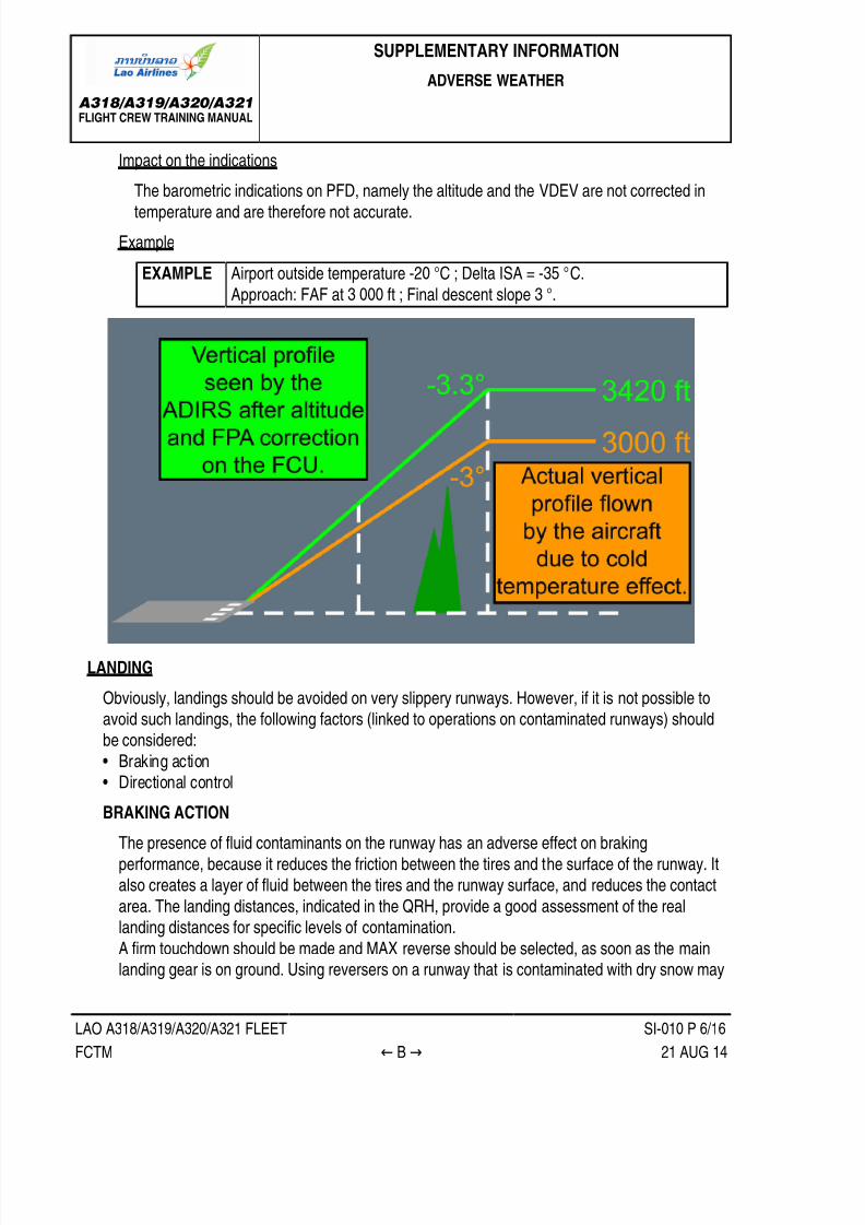
7/21/2019 FCTM date 21-Aug-14
http://slidepdf.com/reader/full/fctm-date-21-aug-14 312/393

7/21/2019 FCTM date 21-Aug-14
http://slidepdf.com/reader/full/fctm-date-21-aug-14 313/393
A318/A319/A320/A321FLIGHT CREW TRAINING MANUAL
SUPPLEMENTARY INFORMATION
ADVERSE WEATHER
LAO A318/A319/A320/A321 FLEET SI-010 P 7/16
FCTM ← B → 21 AUG 14
reduce visibility, particularly at low speeds. In such cases, reverse thrust should be reduced to
idle, if necessary.The use of MED auto-brake is recommended, when landing on an evenly contaminated
runway. It is possible that the DECEL light on the AUTO BRK panel will not come on, as thepredetermined deceleration may not be achieved. This does not mean that the auto-brake is notworking.
In the case of uneven contamination on a wet or contaminated runway, the autobrake maylaterally destabilize the aircraft. If this occurs, consider deselecting the autobrake.
Typical Landing Distance Factors Versus Runway Condition
DIRECTIONAL CONTROL
During rollout, the sidestick must be centered. This prevents asymmetric wheel loading, that
results in asymmetric braking and increases the weathercock tendency of the aircraft.The rudder should be used for directional control after touchdown, in the same way as for a
normal landing. Use of the tiller must be avoided above taxi speed, because it may result innosewheel skidding, and lead to a loss of directional control.When required, differential braking must be applied by completely releasing the pedal on the
side that is opposite to the expected direction of the turn. This is because, on a slippery runway,the same braking effect may be produced by a full or half-deflection of the pedal.

7/21/2019 FCTM date 21-Aug-14
http://slidepdf.com/reader/full/fctm-date-21-aug-14 314/393
A318/A319/A320/A321FLIGHT CREW TRAINING MANUAL
SUPPLEMENTARY INFORMATION
ADVERSE WEATHER
LAO A318/A319/A320/A321 FLEET SI-010 P 8/16
FCTM ← B to C → 21 AUG 14
Landing on a contaminated runway in crosswind requires careful consideration. In such a case,
directional control problems are caused by two different factors:• If the aircraft touches down with some crab and the reverse thrust is selected, the side force
component of reverse adds to the crosswind component and causes the aircraft to drift to the
downwind side of the runway.• As the braking efficiency increases, the cornering force of the main wheels decreases. This
adds to any problems there may be with directional control.
If there is a problem with directional control:‐ Reverse thrust should be set to idle, in order to reduce the reverse thrust side-force
component.
‐ The brakes should be released, in order to increase the cornering force.‐ The pilot should return to the runway centerline, reselect reverse thrust, and resume braking
(Refer to NO-170 ROLL OUT ).
TAXI IN
During taxi-in, after landing, the flaps/slats should not be retracted. This is because retractioncould cause damage, by crushing any ice that is in the slots of the slats. When the aircraft arrives
at the gate, and the engines are stopped, a visual inspection should be performed to check thatthe slats/flaps areas are free of contamination. They may then be retracted, with the electric
pumps.PARKING
At the end of the flight, in extreme cold conditions, cold soak protection is requested when a longerstop over is expected.
TURBULENCE
Ident.: SI-010-00005703.0001001 / 26 MAY 14
Applicable to: ALL
PREFACE
The flight crew must use weather reports and charts to determine the location and altitude ofpossible CBs, storms, and Clear Air Turbulence (CAT). If turbulence is expected, the flight crew
must turn on the seatbelt signs, in order to prepare passengers and prevent injury.
TAKE-OFF
For takeoff in high turbulence, the flight crew must wait for the target speed +20 kt (limited toVFE-5) before retracting the slats/flaps (e.g. the flight crew must wait for F+20 kt before setting
Flaps 1).

7/21/2019 FCTM date 21-Aug-14
http://slidepdf.com/reader/full/fctm-date-21-aug-14 315/393
A318/A319/A320/A321FLIGHT CREW TRAINING MANUAL
SUPPLEMENTARY INFORMATION
ADVERSE WEATHER
LAO A318/A319/A320/A321 FLEET SI-010 P 9/16
FCTM ← C 21 AUG 14
2 IN FLIGHT
USE OF RADAR
Areas of known turbulence, associated with CBs, must be avoided. Good management of the
radar tilt is essential, in order to accurately assess and evaluate the vertical development ofCBs. Usually, the gain should be left in AUTO. However, selective use of manual gain may help
to assess the general weather conditions. Manual gain is particularly useful, when operating inheavy rain, if the radar picture is saturated. In this case, reduced gain will help the flight crewto identify the areas of heaviest rainfall, that are usually associated with active CB cells. After
using manual gain, it should be reset to AUTO, in order to recover optimum radar sensitivity.A weak echo should not be a reason for the flight crew to underestimate a CB, because only
the wet parts of the CB are detected. The decision to avoid a CB must be taken as early aspossible, and lateral avoidance should, ideally, be at 20 nm upwind.
USE OF AP AND A/THR
If moderate turbulence is encountered, the flight crew should set the AP and A/THR to ON with
managed speed.If severe turbulence is encountered, the flight crew should keep the AP engaged. Thrust leversshould be set to turbulence N1 (Refer to QRH), and the A/THR should then be disconnected.
Use of the A/THR is, however, recommended during approach, in order to benefit from the GS
mini.If the aircraft is flown manually, the flight crew should be aware of the fact that flight controllaws are designed to cope with turbulence. Therefore, they should avoid the temptation to fight
turbulence, and should not over-control the sidestick.
CONSIDERATIONS ON CAT
Clear Air Turbulence (CAT) can be expected by referring to weather charts and pilot reports.However, the radar cannot detect CAT, because it is "dry turbulence".
If CAT is encountered, the flight crew may consider avoiding it vertically, keeping in mind that
the buffet margin reduces as the altitude increases.MISCELLANEOUS
• The flight crew must set the harness to on, check that the seat belts signs are on and use all
white lights in thunderstorms.• Turbulence speeds are indicated in the QRH.

7/21/2019 FCTM date 21-Aug-14
http://slidepdf.com/reader/full/fctm-date-21-aug-14 316/393
A318/A319/A320/A321FLIGHT CREW TRAINING MANUAL
SUPPLEMENTARY INFORMATION
ADVERSE WEATHER
LAO A318/A319/A320/A321 FLEET SI-010 P 10/16
FCTM D → 21 AUG 14
WINDSHEAR
Ident.: SI-010-00005705.0001001 / 20 DEC 13Applicable to: ALL
BACKGROUND INFORMATION
WINSHEAR PHENOMENON
The windshear is mostly due to cool shaft of air, like a cylinder between 0.5 nm and 1.5 nm
width that is moving downward. When the air encounters the ground:• Mushrooms horizontally, causing horizontal wind gradient
• Curls inward at the edges, causing vertical air mass movement.
Flight safety is affected, because:• Horizontal wind gradient significantly affects lift, causing the aircraft to descend or to reach
very high AOA.• Vertical air mass movement severely affect the aircraft flight path.
Windshear Phenomenon
AWARENESS AND AVOIDANCE
Awareness of the weather conditions that cause windshear will reduce the risk of an encounter.
Studying meteorological reports and listening to tower reports will help the flight crew to assessthe weather conditions that are to be expected during takeoff or landing.If a windshear encounter is likely, the takeoff or landing should be delayed until the conditions
improve, e.g. until a thunderstorm has moved away from the airport.

7/21/2019 FCTM date 21-Aug-14
http://slidepdf.com/reader/full/fctm-date-21-aug-14 317/393
A318/A319/A320/A321FLIGHT CREW TRAINING MANUAL
SUPPLEMENTARY INFORMATION
ADVERSE WEATHER
LAO A318/A319/A320/A321 FLEET SI-010 P 11/16
FCTM ← D → 21 AUG 14
STRATEGY TO COPE WITH WINDSHEAR
The windshear and microburst are hazardous phenomena for an aircraft at takeoff or landing.The strategy to cope with windshear is:• Increasing flight crew awareness through the Predictive Windshear System (if available)
• Informing the flight crew of unexpected air mass variations through FPV and approachspeed variations
• Warning the flight crew of significant loss of energy through "SPEED, SPEED, SPEED" and"WINDSHEAR" aural warnings (if available).
• Providing effective tools to escape the shear through ALPHA FLOOR protection, SRS pitch
order, high AOA protection and Ground Speed mini protection.
Increasing flight crew awareness (if available)
When the airshaft of a microburst reaches the ground, it mushrooms outward carrying withit a large number of falling rain droplets. The radar can measure speed variations of the
droplets, and as a result, assess wind variations. This predictive capability to assess windvariations is performed by the Predictive Windshear System (PWS). The PWS operates
automatically below 2 300 ft AGL, regardless of whether the radar is turned on or off. OFF.
Informing flight crew
The FPV associated with the approach speed variations (GS mini protection) is an effective
means for informing the flight crew of unexpected air mass variations:Approach speed variations and lateral FPV displacement reflect horizontal wind gradient.Vertical FPV displacement reflects the vertical air mass movement.

7/21/2019 FCTM date 21-Aug-14
http://slidepdf.com/reader/full/fctm-date-21-aug-14 318/393
A318/A319/A320/A321FLIGHT CREW TRAINING MANUAL
SUPPLEMENTARY INFORMATION
ADVERSE WEATHER
LAO A318/A319/A320/A321 FLEET SI-010 P 12/16
FCTM ← D → 21 AUG 14
Bird and Target Speed - Wind Interpretation
Warning the flight crew
The "SPEED, SPEED, SPEED" low energy warning (if available) is based on the aircraftspeed, acceleration and flight path angle. This warning attracts the PF eyes to the speed
scale, and request rapid thrust adjustment. In windshear conditions, it is the first warning toappear, before the activation of the alpha floor. The following table provides some typical
values of the speed at which the warning could occur in two different circumstances.
Deceleration Rate Flight Path Angle Warning
-1 kt/second -3 ° VLS -7 kt
-1 kt/second -4 ° VLS -1 kt
In addition, the aircraft has a reactive windshear warning system. This system triggers ifthe aircraft encounters windshear. In such a case, there is a "WINDSHEAR WINDSHEAR
WINDSHEAR" aural warning.
Providing effictive tools
There are three efficient tools to assist the flight crew to escape:• The alpha floor protection
• the SRS AP/FD pitch law• The high angle of attack protection

7/21/2019 FCTM date 21-Aug-14
http://slidepdf.com/reader/full/fctm-date-21-aug-14 319/393
A318/A319/A320/A321FLIGHT CREW TRAINING MANUAL
SUPPLEMENTARY INFORMATION
ADVERSE WEATHER
LAO A318/A319/A320/A321 FLEET SI-010 P 13/16
FCTM ← D → 21 AUG 14
When the alpha floor protection is triggered, the A/THR triggers TOGA on all engines. The
FMA displays A FLOOR, that changes to TOGA LK, when the aircraft angle-of-attack hasdecreased. TOGA/LK can only be deselected by turning the A/THR off.
The SRS pitch mode ensures the best aircraft climb performance. Therefore, the procedurerequests following the SRS pitch bar and possibly full aft stick, in order to follow the SRSorders and minimize the loss of height.
The high angle-of-attack protection enables the PF to safely pull full aft stick, if needed, inorder to follow the SRS pitch order, or to rapidly counteract a down movement. This provides
maximum lift and minimum drag, by automatically retracting the speed brakes, if they areextended.
OPERATIONAL RECOMMENDATIONSTAKE-OFF
Predictive windshear ("WINDSHEAR AHEAD" aural warning), if available
If predictive windshear aural warning is generated on the runway before take-off, take-off
must be delayed.If a predictive windshear aural warning is generated during the takeoff roll, the Captain must
reject the takeoff (the aural warning is inhibited at speeds greater than 100 kt).
If the predictive windshear aural warning is generated during initial climb, the flight crew must:
• Set TOGA• Closely monitor the speed and the speed trend• Ensure that the flight path does not include areas with suspected shear• Change the aircraft configuration, provided that the aircraft does not enter windshear.
Reactive windshear (WINSHEAR, WINSHEAR, WINSHEAR aural warning) or windsheardetected by pilot observation
If the windshear starts before V1 with significant speed and speed trend variations and the
captain decides that there is sufficient runway to stop the airplane, the captain must initiate a
rejected take-off.If the windshear starts after V1, the crew will set TOGA and will apply the QRH checklistactions from memory. The following points should be stressed:
• The configuration should not be changed until definitely out of the shear, becauseoperating the landing gear doors causes additional drag.
• The PF must fly SRS pitch orders rapidly and smoothly, but not aggressively, and mustconsider the use of full backstick, if necessary, to minimize height loss.
• The PNF should call wind variation from the ND and V/S and, when clear of the shear,report the encounter to ATC.

7/21/2019 FCTM date 21-Aug-14
http://slidepdf.com/reader/full/fctm-date-21-aug-14 320/393
A318/A319/A320/A321FLIGHT CREW TRAINING MANUAL
SUPPLEMENTARY INFORMATION
ADVERSE WEATHER
LAO A318/A319/A320/A321 FLEET SI-010 P 14/16
FCTM ← D to E → 21 AUG 14
APPROACH
Predictive windshear (if available)In case the "MONITOR RADAR DISPLAY" is displayed or the ADVISORY ICON appears,the flight crew should either delay the approach or divert to another airport. However, if theapproach is continued, the flight crew should consider the following:
• The weather severity must be assessed with the radar display.• A more appropriate runway must be considered.
• A Conf 3 landing should be considered.• The flight crew should increase VAPP displayed on MCDU PERF APP page up to a
maximum VLS +15 kt.
• Using the TRK/FPA or ILS, for an earlier detection of vertical path deviation should beconsidered.
• In very difficult weather conditions, the A/THR response time may not be sufficient tomanage the instantaneous loss of airspeed. Refer to NO-110 FINAL APPROACH for the
applicable technique description.• In case the "GO AROUND WINDSHEAR AHEAD" message is triggered, the PF must
set TOGA for go-around. The aircraft configuration can be changed, provided that the
windshear is not entered. Full back stick should be applied, if required, to follow the SRS orminimize loss of height.
Reactive windshear (if available)
In case of the "WINDSHEAR WINDSHEAR WINDSHEAR" aural warning, the PF must set
TOGA for go-around. However, the configuration (slats/flaps, gear) must not be changed untilout of the shear. The flight crew must closely monitor the flight path and speed.
VOLCANIC ASH
Ident.: SI-010-00005706.0001001 / 09 APR 14
Applicable to: ALL
PREFACE
Volcanic ash or dust consists of very abrasive particles, that may cause engine surge and severedamage to aircraft surfaces that are exposed to the airflow. For this reason, operations in volcanic
ash must be avoided. However, if such operations cannot be avoided, the operators should applythe following recommendations.
GROUND OPERATIONS
PRELIMINARY COCKPIT PREPARATION
The use of APU should be avoided whenever possible and the use of the Ground Power Unit(GPU) should be preferred.

7/21/2019 FCTM date 21-Aug-14
http://slidepdf.com/reader/full/fctm-date-21-aug-14 321/393
A318/A319/A320/A321FLIGHT CREW TRAINING MANUAL
SUPPLEMENTARY INFORMATION
ADVERSE WEATHER
LAO A318/A319/A320/A321 FLEET SI-010 P 15/16
FCTM ← E → 21 AUG 14
The wipers will not be used for any reason.
EXTERIOR INSPECTIONMaintenance personnel must remove ash that has settled on exposed lubricated surfacesthat can penetrate seals or enter the engine gas path, air conditioning system, air data probesand other orifices on the aircraft. They must clean the engines air inlet of any volcanic ash. In
addition, they must clean the 25 ft area around the engine inlet.
ENGINE START
The use of an external pneumatic supply should be preferred when possible. If not possible, theAPU may be used to start the engines.
Before starting the engines, the crew must use dry cranking. This will blow out any ash that mayhave entered the booster area.
TAXI
The flight crew must move forward the thrust levers smoothly to the minimum required thrust to
taxi, and must avoid any sharp or high-speed turns. The bleeds must be kept OFF.
TAKE-OFF
It is advisable to use the rolling takeoff technique, and smoothly apply thrust.
3 IN FLIGHT
CRUISE
The flight crew must avoid flying into areas of known volcanic ash. If a volcanic eruption is
reported, while the aircraft is in flight, the flight must be rerouted to remain clear of the affectedarea. The volcanic dust may spread over several hundred miles. Whenever possible, the flight
crew should stay on the upwind side of the volcano.Depending on outside conditions (night flight, clouds), volcanic dust might not be visible.
However, several phenomena can indicate that the aircraft is flying through ash cloud, for
example:• Smoke or dust in the cockpit• Acrid odour similar to electrical smoke
• Engine malfunction, e.g. a rising EGT• At night, the appearance of St Elmo fire, bright white or orange glow appearing in engine
inlets or sharp and distinct beams from the landing lights.

7/21/2019 FCTM date 21-Aug-14
http://slidepdf.com/reader/full/fctm-date-21-aug-14 322/393
A318/A319/A320/A321FLIGHT CREW TRAINING MANUAL
SUPPLEMENTARY INFORMATION
ADVERSE WEATHER
LAO A318/A319/A320/A321 FLEET SI-010 P 16/16
FCTM ← E 21 AUG 14
If an ash cloud is encountered, the applicable procedure is described in the QRH. The essential
actions to be taken are:• 180 ° turn if possible. This is the quickest way to escape, because the ash cloud lateral
dimension is not known
• Protecting the engines:‐ Set A/THR to OFF
‐ Decrease engines thrust if possible and maximize engine bleed to increase the enginesurge margin
‐ If engine restart is required, consider delaying engine start and APU start until out of the
volcanic ash cloud.
• Protecting the flight crew and passengers:‐ Don the oxygen mask‐ Consider oxygen for the passengers.
• Monitoring the flight parameters:
‐ Monitor the EGT and fuel flow, because an engine part may be eroded‐ Monitor and cross-check the IAS because an IAS indication may be corrupted
A diversion to the nearest appropriate airport should be considered.
LANDING
The use of reverse should be avoided, unless necessary.

7/21/2019 FCTM date 21-Aug-14
http://slidepdf.com/reader/full/fctm-date-21-aug-14 323/393
A318/A319/A320/A321FLIGHT CREW TRAINING MANUAL
SUPPLEMENTARY INFORMATION
FLYING REFERENCE
LAO A318/A319/A320/A321 FLEET SI-020 P 1/4
FCTM A to C → 06 MAR 14
GENERAL
Ident.: SI-020-00005709.0001001 / 26 MAR 08Applicable to: ALL
Two flying references may be used on the PFD:
• The attitude• The Flight Path Vector (FPV), called the "bird".
The pilot selects the flight reference with the HDG/VS TRK/FPA p/b on the FCU.
THE ATTITUDE
Ident.: SI-020-00005710.0001001 / 26 MAR 08Applicable to: ALL
When HDG/VS is selected on the FCU, "bird" is off, and the attitude is the flight reference with HDGand VS as basic guidance parameters.
The attitude flight reference should be used for dynamic manoeuvres, for example, take-off orgo-around. An action on the sidestick has an immediate effect on the aircraft attitude. The flight crewcan monitor this flight reference directly and accurately during these maneuvers.
THE FLIGHT PATH VECTOR
Ident.: SI-020-00005711.0001001 / 20 DEC 13Applicable to: ALL
When TRK/FPA is selected on the FCU, the "bird" (the FPV) is the flight reference with the TRK andFPA as basic guidance parameters.
In dynamic manoeuvres, the "bird" is directly affected by the aircraft inertia and has a delayedreaction. As a result, the "bird" should not be used as a flight reference in dynamic manoeuvres.
The "bird" is the flying reference that should be used when flying a stabilized segment of trajectory,e.g. a non Precision Approach or visual circuit.
INFORMATION PRESENTATION
The FPV appears on the PFD as a symbol, known as "the bird". The bird indicates the track and
flight path angle in relation to the ground.The track is indicated on the PFD by a green diamond on the compass, in addition to the lateral
movement of the bird in relation to the fixed aircraft symbol. On the ND, the track is indicatedby a green diamond on the compass scale. The difference in angle between track and headingindicates the drift.
The flight path angle is indicated on the PFD by the vertical movement of the bird in relation to thepitch scale.

7/21/2019 FCTM date 21-Aug-14
http://slidepdf.com/reader/full/fctm-date-21-aug-14 324/393
A318/A319/A320/A321FLIGHT CREW TRAINING MANUAL
SUPPLEMENTARY INFORMATION
FLYING REFERENCE
LAO A318/A319/A320/A321 FLEET SI-020 P 2/4
FCTM ← C → 06 MAR 14
Use of FPV
With the flight directors (FDs) selected ON, the Flight Path Director (FPD) replaces the HDG-VSFlight Director (FD). With both FDs pb set to off, the blue track index appears on the PFD horizon.
PRACTICAL USES OF THE FPV
As a general rule, when using the bird, the pilot should first change attitude, and then check theresult with reference to the bird.
NON-PRECISION APPROACH
The FPV is particularly useful for non-precision approaches. The pilot can select values for the
inbound track and final descent path angle on the FCU. Once established inbound, only minorcorrections should be required to maintain an accurate approach path. The pilot can monitor thetracking and descent flight path, with reference to the track indicator and the bird.

7/21/2019 FCTM date 21-Aug-14
http://slidepdf.com/reader/full/fctm-date-21-aug-14 325/393
A318/A319/A320/A321FLIGHT CREW TRAINING MANUAL
SUPPLEMENTARY INFORMATION
FLYING REFERENCE
LAO A318/A319/A320/A321 FLEET SI-020 P 3/4
FCTM ← C → 06 MAR 14
However, pilots should understand that the bird only indicates a flight path angle and track, and
does not provide guidance to a ground-based radio facility. Therefore, even if the bird indicatesthat the aircraft is flying with the correct flight path angle and track, this does not necessarily
mean that the aircraft is on the correct final approach path.
VISUAL CIRCUITS
The FPV can be used as a cross-reference, when flying visual circuits. On the downwind leg,the pilot should position the wings of the bird on the horizon, in order to maintain level flight. The
downwind track should be set on the FCU. The pilot should position the tail of the bird on theblue track index on the PFD , in order to maintain the desired track downwind.On the final inbound approach, the track index should be set to the final approach course of the
runway. A standard 3 ° approach path is indicated, when the top of the bird's tail is immediatelybelow the horizon, and the bottom of the bird is immediately above the 5 ° nose down marker.
Use of FPV in Final Approach
FINAL APPROACH
The bird is a very useful flight reference, because it provides the trajectory parameters, and
quickly warns the pilot of downburst. In addition, together with the GS MINI protection, it isan excellent indicator of shears or wind variations. The position of the "bird" in relation to the
fixed aircraft symbol provides an immediate indication of the wind direction. Therefore, when
approaching the minima, the pilot knows in which direction to search for the runway.

7/21/2019 FCTM date 21-Aug-14
http://slidepdf.com/reader/full/fctm-date-21-aug-14 326/393

7/21/2019 FCTM date 21-Aug-14
http://slidepdf.com/reader/full/fctm-date-21-aug-14 327/393
A318/A319/A320/A321FLIGHT CREW TRAINING MANUAL
SUPPLEMENTARY INFORMATION
NAVIGATION ACCURACY
LAO A318/A319/A320/A321 FLEET SI-030 P 1/8
FCTM A to B → 06 MAR 14
GENERAL
Ident.: SI-030-00005713.0001001 / 26 MAR 08Applicable to: ALL
The primary function of the FMS is navigation i.e. to compute the aircraft's position as accurately as
possible. The validity of all the others functions depends upon the accuracy of the FMS position.The accuracy of the FMS navigation determines the flight crew's strategy for using the AP/FDmodes, in addition to the ND display.
AIRCRAFT POSITION COMPUTATION
Ident.: SI-030-00005715.0001001 / 20 DEC 13
Applicable to: ALL
WITHOUT GPS PRIMARY
PRINCIPLE
Each FMS computes its own aircraft position from the three IRS (MIXIRS) position and a
computed radio position.
The computed radio position is a combination between the available navaids:‐ DME/DME
‐ VOR/DME‐ LOC‐ DME/DME-LOC
‐ VOR/DME-LOC
The FMS always uses the MIXIRS position and selects the most accurate source of radioposition. To select this most accurate source, the FMS considers the estimated accuracy and
integrity of each positioning equipment.
INITIALISATION
Refer to NO-020 ADIRS Alignment or Realignment
TAKE-OFF
Each FMGC uses the MIXIRS position as its position, until the thrust levers are pushed forward
to TOGA. The FMS position is then updated to the runway threshold coordinates. The differencebetween the MIXIRS position and the FMS position is referred to as the TO BIAS. The TO BIASis added to the MIXIRS position, for the subsequent FMS position.

7/21/2019 FCTM date 21-Aug-14
http://slidepdf.com/reader/full/fctm-date-21-aug-14 328/393
A318/A319/A320/A321FLIGHT CREW TRAINING MANUAL
SUPPLEMENTARY INFORMATION
NAVIGATION ACCURACY
LAO A318/A319/A320/A321 FLEET SI-030 P 2/8
FCTM ← B → 06 MAR 14
FMS Position Updating at Take Off
IN FLIGHT
The original TO BIAS is continuously updated with the current radio aid.
Updating BIAS Principle
If the radio position is lost, the system uses the updated BIAS to determine the FMS positionfrom the MIXIRS position.
NAVIGATION ACCURACY
The FMS computes the Estimated Position Uncertainty (EPU). The EPU is an estimate of howmuch the FM position diverges (value with 95% of confidence on the computed position) , anddepends on the navigation mode that the system uses.

7/21/2019 FCTM date 21-Aug-14
http://slidepdf.com/reader/full/fctm-date-21-aug-14 329/393
A318/A319/A320/A321FLIGHT CREW TRAINING MANUAL
SUPPLEMENTARY INFORMATION
NAVIGATION ACCURACY
LAO A318/A319/A320/A321 FLEET SI-030 P 3/8
FCTM ← B → 06 MAR 14
The FMS compares the EPU with the Required Navigation Performance (RNP) to determine the
level of navigation accuracy:‐ If the EPU does not exceed the RNP, accuracy is HIGH‐ If the EPU exceeds the RNP, accuracy is LOW.
The class of navigation accuracy is displayed continuously on the MCDU PROG page. The
RNP is displayed in the REQUIRED field of the MCDU PROG page.
WITH GPS PRIMARY
PRINCIPLE
The GPS interfaces directly with the IRS that outputs a GPIRS position. When a GPIRS position
is available, it overrides the RADIO position, if available. Therefore, the FMS position tendstoward the GPIRS position.
INITIALISATION
Refer to NO-020 ADIRS Alignment or Realignment
TAKE-OFF
The FM position is automatically updated at the runway threshold. With FMS2, this automatic
position update is inhibited.
IN FLIGHT
The FM position tends to the GPIRS position as long as the GPS satellites are available.
NAVIGATION ACCURACY
The GPIRS position is characterized by two parameters:
• Integrity• Accuracy
The IRS continuously monitors the integrity and the accuracy of the GPIRS position. The
GPIRS integrity is a direct function of the number of satellites in view of the aircraft. If five ormore satellites are in view, several combinations of the satellite signal may be used to process"several positions" and to carry out reasonableness tests on the satellite signals themselves.
GPIRS accuracy is in direct connection with the satellite constellation in view of the aircraft.If the satellites are low on horizon, or not in appropriate positions, accuracy will be poor. It is
provided as a "figure of merit".If the GPIRS position fulfils both the integrity and the accuracy criteria, GPS PRIMARY isdisplayed on the MCDU PROG page.

7/21/2019 FCTM date 21-Aug-14
http://slidepdf.com/reader/full/fctm-date-21-aug-14 330/393
A318/A319/A320/A321FLIGHT CREW TRAINING MANUAL
SUPPLEMENTARY INFORMATION
NAVIGATION ACCURACY
LAO A318/A319/A320/A321 FLEET SI-030 P 4/8
FCTM ← B to C → 06 MAR 14
SUMMARY
FM POSITIONFlight phase WITHOUT GPS PRIMARY WITH GPS PRIMARY
On groundbefore Takeoff MIXIRS GPIRS
Takeoff Updated at runway threshold (shift) (1)
With RADIO Tends to RADIO GPIRSIn flight
Without RADIO MIXIRS + BIAS GPIRS
(1) The FMS position update at take-off is inhibited with FMS2 when GPS PRIMARY is active.
USE OF FMS
Ident.: SI-030-00005717.0001001 / 09 JUN 10Applicable to: ALL
The navigation accuracy is managed through several MCDU pages:
PROG PAGE
This page indicates the GPS PRIMARY status.
The PROG page also displays in green the estimated navigation (EPU) accuracy that the FMScomputes with the GPS or the radio position.The EPU is compared to the required navigation accuracy displayed in blue (this can be changed).
The required navigation accuracy thresholds are determined, depending on the flight phase, orcan be manually entered. These thresholds are used to change from HIGH to LOW accuracy, or
from GPS PRIMARY or GPS PRIMARY LOST and vice versa. These indications are used whenflying within RNP airspace.
SELECTED NAVAIDS PAGE
The SELECTED NAVAID page is accessible from DATA/POSITION MONITOR/ FREEZE/SEL
NAVAIDS. It has a DESELECT prompt, that enables the flight crew to prevent the FMS from usingthe GPS data to compute the position. If the flight crew deselects the GPS, GPSPRIMARY lost is
then displayed on MCDU and ND. The GPS can be reselected using the same prompt.
PREDICTIVE GPS PAGE (IRS HONEYWELL ONLY)
The PREDICTIVE GPS page is accessible from PROG page. The GPS PRIMARY criteriadepends on the satellite constellation status (position and number) and this is predictable. The
crew can assess the GPS PRIMARY status at destination or alternate.
ND/MCDU
A GPS PRIMARY message is displayed when GPS PRIMARY is again available. This message isclearable.
A GPS PRIMARY LOST message is displayed when GPS PRIMARY is lost. This message isclearable on MCDU but not on ND.

7/21/2019 FCTM date 21-Aug-14
http://slidepdf.com/reader/full/fctm-date-21-aug-14 331/393
A318/A319/A320/A321FLIGHT CREW TRAINING MANUAL
SUPPLEMENTARY INFORMATION
NAVIGATION ACCURACY
LAO A318/A319/A320/A321 FLEET SI-030 P 5/8
FCTM ← C to D → 06 MAR 14
When the class of navigation accuracy is downgraded from HIGH to LOW (LOW to HIGH), a NAV
ACCUR DOWNGRADE (UPGRADE) is displayed on ND and MCDU.
AIRCRAFT POSITION AWARENESS AND OPERATIONAL CONSEQUENCES
Ident.: SI-030-00005719.0001001 / 20 DEC 13Applicable to: ALL
NAVIGATION ACCURACY INDICATIONS
The navigation accuracy indications are available on the MCDU PROG page. The following
guidelines apply:• If GPS PRIMARY is displayed, no navigation cross-check is required
• If GPS PRIMARY LOST, navigation cross-check is required in climb, in cruise, about every45 min, before Top Of Descent, reaching TMA and IAF and whenever a navigation doubt
occurs.• The crew will use, IRS only, LOW and NAV ACCUR DOWNGRAD messages as indications to
trigger a navigation accuracy check.
NAVIGATION ACCURACY CROSSCHECK TECHNIQUE
The principle consists in comparing the FMS position with the RADIO position (aircraft realposition).

7/21/2019 FCTM date 21-Aug-14
http://slidepdf.com/reader/full/fctm-date-21-aug-14 332/393
A318/A319/A320/A321FLIGHT CREW TRAINING MANUAL
SUPPLEMENTARY INFORMATION
NAVIGATION ACCURACY
LAO A318/A319/A320/A321 FLEET SI-030 P 6/8
FCTM ← D → 06 MAR 14
Navigation Accuracy Cross Check Technique 1
Two different techniques may be used:
• Either the crew will insert a radio ident in MCDU PROG page (which provides a bearing/distancerelative to FMS position) and will compare with raw data received from the NAVAID which
materializes the aircraft real position. This allows the error Epsilon to be quantified.• On the ND, the flight crew compares: The position of the needle and its associated DME
distance (the real position of the aircraft) with the position of the NAVAID symbol and itsassociated distance, indicated by the range markers (these markers provide a bearing/distance,in relation to the FMS position).

7/21/2019 FCTM date 21-Aug-14
http://slidepdf.com/reader/full/fctm-date-21-aug-14 333/393
A318/A319/A320/A321FLIGHT CREW TRAINING MANUAL
SUPPLEMENTARY INFORMATION
NAVIGATION ACCURACY
LAO A318/A319/A320/A321 FLEET SI-030 P 7/8
FCTM ← D → 06 MAR 14
Navigation Accuracy Cross Check Technique 2
OPERATIONAL CONSEQUENCES
The result of the navigation accuracy crosscheck dictates the strategy the pilot will apply for theuse of the ND display, the AP/FD modes, and EGPWS.
NDPF PNF
AP/FD mode EGPWS
GPS PRIMARY - Arc or Rose NAV with
raw data when required
Lateral and vertical
managed modes
ON
Navigation accuracycheck positive(≤ 3 nm)
Arc or Rose NAV withraw data when required
Lateral and verticalmanaged modes
ONCruise
Navigation accuracycheck negative(>3 nm)
ARC or ROSE NAVmay be used with care
and with raw data
Lateral andvertical managedmodes with care
with raw data
OFF
Navigation accuracycheck positive(≤ 1 nm)
Arc or Rose NAV with raw data Lateral and verticalmanaged modes
ON
GPSPRIMARY
LOST OrNo GPS
Approach (1)
Navigation accuracycheck negative(>1 nm)
ROSE VOR or ILS as required Lateral and verticalselected modes
OFF
(1) A GPS defined Non Precision Approach must be interrupted if GPS PRIMARY LOST message is displayed.
POSITION UPDATE
In case of an obvious and major map shift noticed by specific messages such as "CHECK A/CPOSITION, FM1/FM2 POS MISMATCH", the aircraft position may be updated on the MCDU
PROG page. Two techniques are available:
The recommended technique is to carry out a FMS update over a beacon by pressing theUPDATE prompt once estimating that the aircraft overflies the beacon using the associated

7/21/2019 FCTM date 21-Aug-14
http://slidepdf.com/reader/full/fctm-date-21-aug-14 334/393
A318/A319/A320/A321FLIGHT CREW TRAINING MANUAL
SUPPLEMENTARY INFORMATION
NAVIGATION ACCURACY
LAO A318/A319/A320/A321 FLEET SI-030 P 8/8
FCTM ← D 06 MAR 14
needle. The potential error induced is approximately 4 to 5 nm. When the position update is
achieved, the EPE is automatically set to a higher value and the navigation accuracy is low.The second technique consists in updating the FM position when flying over a
Point/Bearing/Distance (P/B/D) with reference to beacon raw data (Needle + Distance) rather thanthe beacon itself. The potential for error is far less when the distance is greater than 60 nm. Theflight crew will keep in mind the potential 180 ° error on bearing.
FM Position Update in Flight

7/21/2019 FCTM date 21-Aug-14
http://slidepdf.com/reader/full/fctm-date-21-aug-14 335/393
A318/A319/A320/A321FLIGHT CREW TRAINING MANUAL
SUPPLEMENTARY INFORMATION
ZFW - ZFCG ENTRY ERRORS
LAO A318/A319/A320/A321 FLEET SI-040 P 1/4
FCTM A to B → 06 MAR 14
GENERAL
Ident.: SI-040-00005722.0001001 / 26 MAR 08Applicable to: ALL
The aircraft Gross Weight (GW) and Centre of Gravity (CG) are computed independently by the FM
and FAC:GW and CG values FM computed are used for:• FM predictions and speeds
• ECAM (GW)• MCDU (GW and CG)
GW and CG values FAC computed are used for:
• Flight control laws• Computation of characteristic speeds (VLS, F, S, GD) for display on PFD
A ZFW or ZFWCG entry error in MCDU INIT B page induces calculation errors that are to behighlighted.
TECHNICAL BACKGROUND
Ident.: SI-040-00005723.0001001 / 20 DEC 13
Applicable to: ALL
The GW and CG computation is as follows:1. The pilot enters the ZFW and ZFWCG in the MCDU INIT B page2. The FMGC computes the GW and CG from:
• The ZFW, ZFWCG inserted in the MCDU INIT B page• The fuel quantities from the Fuel Quantity Indicator (FQI)
• The Fuel Flow from the FADEC.3. This current GW and/or CG is used for:
• FM predictions and speeds• ECAM (GW only)• MCDU (GW and CG).
4. The FAC computes its own GW and CG from aerodynamic data.5. GW and CG FAC computed are used for:
• Minor adjustments on the flight control laws• Characteristic speeds (VLS, F, S, Green dot) display on PFD.

7/21/2019 FCTM date 21-Aug-14
http://slidepdf.com/reader/full/fctm-date-21-aug-14 336/393
A318/A319/A320/A321FLIGHT CREW TRAINING MANUAL
SUPPLEMENTARY INFORMATION
ZFW - ZFCG ENTRY ERRORS
LAO A318/A319/A320/A321 FLEET SI-040 P 2/4
FCTM ← B 06 MAR 14
Note: 1. On ground, FAC uses the GW FM computed.
2. In flight, at low altitude (below 15 000 ft), low speed (below 250 kt) and flight parameters stabilized, GW FAC computed comes from aerodynamic data. If these conditions are not met, GW FAC computed equates to the last memorized GW - fuel used.
3. If the GW FM computed and FAC computed differs from a given threshold, a "CHECK
GW" message appears on the MCDU scratchpad.

7/21/2019 FCTM date 21-Aug-14
http://slidepdf.com/reader/full/fctm-date-21-aug-14 337/393
A318/A319/A320/A321FLIGHT CREW TRAINING MANUAL
SUPPLEMENTARY INFORMATION
ZFW - ZFCG ENTRY ERRORS
LAO A318/A319/A320/A321 FLEET SI-040 P 3/4
FCTM C to D 06 MAR 14
ZFW ENTRY ERROR AND OPERATIONAL CONSEQUENCES
Ident.: SI-040-00005724.0001001 / 22 APR 08Applicable to: ALL
If the pilot enters erroneous ZFW on MCDU INIT B page, this will affect as follows:
GW and, to a lesser degree, CG, computed by FM are erroneous. This induces the followingconsequences:• The FM predictions and speeds are erroneous
• Incorrect GW and CG on MCDU FUEL PRED page• Incorrect GW displayed on ECAM
FAC GW, which is based on FM GW on ground, will be updated only once airborne through a
specific slow calculation using AOA information. Consequently,• Characteristic speeds on PFD at take-off are erroneous, but they are correct in flight
• SRS mode guidance is affected if computed VLS is above V2 as inserted in the MCDU PERFTAKE-OFF page.
Note: 1. In flight, if the FM and FAC GW differ from a given threshold, a "CHECK GW" message is
triggered on the MCDU.2. Valpha prot, Valpha max, Vsw are not affected since based on aerodynamic data.
ERRONEOUS FUEL ON BOARD ENTRY
As long as the engines are not started, the FM GW is erroneous and above-mentionedconsequences apply. Once the engines are started, the fuel figures are updated and downstreamdata update accordingly.
It should be noted however, that the FOB on ECAM is correct since it is provided from FQI data.
OPERATIONAL RECOMMENDATIONS
Ident.: SI-040-00005726.0001001 / 26 MAR 08Applicable to: ALL
ZFW entries should be cross-checked by both crew members to avoid entry error.
If the "CHECK GW" amber warning is displayed on the MCDU, a significant discrepancy existsbetween the FM computed GW and the FAC computed GW.
The crew will compare the Load and Trim Sheet (LTS) figures with the FM GW and fuel used:
• If an obvious entry error is detected, FM GW will be updated on the MCDU FUEL PRED page.• If FM and LTS GW are in accordance and appear to be correct, the FAC computed GW should
be suspected. (AOA sensor problem). Consequently, characteristic speeds on PFD are erroneousand should be disregarded. Characteristic speeds should be extracted from QRH.
• If FM and LTS GW are in accordance but LTS GW is suspected, FAC and QRH characteristic
speeds should be compared (to validate FAC outputs) and the most appropriate applied.

7/21/2019 FCTM date 21-Aug-14
http://slidepdf.com/reader/full/fctm-date-21-aug-14 338/393
A318/A319/A320/A321FLIGHT CREW TRAINING MANUAL
SUPPLEMENTARY INFORMATION
ZFW - ZFCG ENTRY ERRORS
Intentionally left blank
LAO A318/A319/A320/A321 FLEET SI-040 P 4/4
FCTM 06 MAR 14

7/21/2019 FCTM date 21-Aug-14
http://slidepdf.com/reader/full/fctm-date-21-aug-14 339/393
A318/A319/A320/A321FLIGHT CREW TRAINING MANUAL
SUPPLEMENTARY INFORMATION
TCAS
LAO A318/A319/A320/A321 FLEET SI-060 P 1/4
FCTM A → 06 MAR 14
TECHNICAL BACKGROUND
Ident.: SI-060-00005727.0001001 / 20 DEC 13Applicable to: ALL
GENERAL
A Traffic Alert and Collision Avoidance System (TCAS) provides the flight crew with trafficinformation and warnings of potential conflicts with vertical avoidance instructions. The TCAS canonly detect and indicate other traffic, that is equipped with a transponder.
The ND displays the traffic information, together with:• The bearing and range to the intruder
• The intruder closure rate• The relative altitude difference.
If the TCAS considers the intruder to be a potential collision threat, it generates a visual and auralTraffic Advisory (TA). If it considers the intruder to be real collision threat, it generates a visual andaural Resolution Advisory (RA).
INTRUDER CLASSIFICATION
Intruder DisplayType of
collision threatAural warning Crew action
No threat traffic orothers
No threat - -
Proximate Consider as No threat - -
Traffic Advisory (TA) Potential threat "TRAFFIC TRAFFIC" No evasive maneuver
Continued on the following page

7/21/2019 FCTM date 21-Aug-14
http://slidepdf.com/reader/full/fctm-date-21-aug-14 340/393
A318/A319/A320/A321FLIGHT CREW TRAINING MANUAL
SUPPLEMENTARY INFORMATION
TCAS
LAO A318/A319/A320/A321 FLEET SI-060 P 2/4
FCTM ← A to B → 06 MAR 14
Continued from the previous page
Intruder Display
Type of
collision threat Aural warning Crew actionPreventive, e.g."MONITOR V/S"
Do not alter your flightpath and keep VS outof red sector
Corrective, e.g."CLIMB"
Smoothly and firmly(0.25 g) follow VSIgreen sector within 5 s
Resolution Advisory(RA)
Collision threat
Corrective, e.g."CLIMB NOW" or"INCREASE CLIMB"
Smoothly and firmly(0.35 g) follow VSIgreen sector within
2.5 s
OPERATIONAL RECOMMENDATIONS
Ident.: SI-060-00005731.0001001 / 24 FEB 14Applicable to: ALL
The flight crew should select• ABV in climb (+9 900 ft/-2 700 ft or +7 000 ft/-2 700 ft, depending on the type of TCAS control
panel)• ALL in cruise (+2 700 ft/-2 700 ft)
• BELOW , if the cruise altitude is within 2 000 ft of FL 410, or in descent (+2 700 ft/-9 900 ft or+2 700 ft/-7 000 ft, depending on the type of TCAS control panel)
• THRT in heavy traffic terminal area• TA, in the case of:
‐ Engine failure‐ Flight with landing gear down‐ Operations at specific airports, and during specific procedures that an operator identifies as
having a significant potential for not wanted and not appropriate RAs, e.g. closely spacedparallel runways, converging runways.
The flight crew should comply with the vertical speed limitations during the last 2 000 ft of a climbor descent. In particular, the flight crew should limit vertical speeds to 1 500 ft/min during the last2 000 ft of a climb or descent, especially when they are aware of traffic that is converging in altitudeand intending to level off 1 000 ft above or below the flight crew's assigned altitude.
If a TA is generated:• The PF announces: "TCAS, I have controls".• No evasive maneuver should be initiated, only on the basis of a TA.

7/21/2019 FCTM date 21-Aug-14
http://slidepdf.com/reader/full/fctm-date-21-aug-14 341/393
A318/A319/A320/A321FLIGHT CREW TRAINING MANUAL
SUPPLEMENTARY INFORMATION
TCAS
LAO A318/A319/A320/A321 FLEET SI-060 P 3/4
FCTM ← B 06 MAR 14
If a RA is generated:
• The flight crew must always follow the TCAS RA orders in the correct direction, even:‐ If the TCAS RA orders are in contradiction with the ATC instructions‐ At the maximum ceiling altitude with CLIMB, CLIMB or INCREASE CLIMB, INCREASE CLIMB
TCAS RA orders‐ If it results in crossing the altitude of the intruder.
CAUTION If a pilot does not follow a RA, he should be aware that the intruder may beTCAS equipped and may be maneuvering toward his aircraft in response to acoordinated RA. This could compromize safe separation.
• The PF disconnects the AP, and smoothly and firmly follows the Vertical Speed Indicator (VSI)green sector within 5 s, and requests that both FDs be disconnected.
Note: Both FDs must be disconnected once APs are disconnected:
‐ To ensure autothrust speed mode ‐ To avoid possible confusion between FD bar orders and, TCAS aural and VSI orders
• The PNF disconnects both FDs, but will not try to see intruders.• The PF will avoid excessive maneuvers, and keep the Vertical Speed outside the red area of the
VSI and within the green area. If necessary, the PF must use the full speed range between Valphamax and Vmax.
• The PNF must notify ATC.• The flight crew should never maneuver in the opposite direction of the RA, because TCAS
maneuvers are coordinated.• In final approach, i.e. "CLIMB", "CLIMB NOW", "INCREASE CLIMB", the flight crew will initiate a
go-around.
When clear of conflict:• The flight crew must resume normal navigation, in accordance with ATC clearance, and using the
AP, as required.

7/21/2019 FCTM date 21-Aug-14
http://slidepdf.com/reader/full/fctm-date-21-aug-14 342/393
A318/A319/A320/A321FLIGHT CREW TRAINING MANUAL
SUPPLEMENTARY INFORMATION
TCAS
Intentionally left blank
LAO A318/A319/A320/A321 FLEET SI-060 P 4/4
FCTM 06 MAR 14

7/21/2019 FCTM date 21-Aug-14
http://slidepdf.com/reader/full/fctm-date-21-aug-14 343/393
A318/A319/A320/A321FLIGHT CREW TRAINING MANUAL
SUPPLEMENTARY INFORMATION
USE OF RADAR
LAO A318/A319/A320/A321 FLEET SI-070 P 1/8
FCTM A to B → 06 MAR 14
GENERAL
Ident.: SI-070-00005738.0001001 / 09 JUN 10Applicable to: ALL
The weather radar has two main functions:‐ Weather detection‐ Ground Mapping.
WEATHER DETECTION
Weather detection is based on the reflectivity of the water droplets.The intensity of the weather echo is linked to the droplet size, composition and quantity (e.g. the
reflection of water particles is five times greater than ice particles of the same size).
The crew must be aware that the weather radar does not detect weather that has small droplets(e.g. clouds or fog), or that does not have droplets (e.g. clear air turbulence).
GROUND MAPPING
Ground mapping is the secondary function of the radar.In MAP mode, the ND displays ground echoes in various colors depending on their altitude andintensity.
WEATHER RADAR CONTROLS AND FUNCTIONS
Ident.: SI-070-00005733.0001001 / 20 DEC 13Applicable to: ALL
The flight crew uses the following controls and functions to operate the radar.
TILT
Tilt refers to the angle between the antenna and the horizon.The radar uses IRS data to stabilize its antenna. As a consequence, antenna tilt is independent
from the aircraft's pitch and bank angles.

7/21/2019 FCTM date 21-Aug-14
http://slidepdf.com/reader/full/fctm-date-21-aug-14 344/393
A318/A319/A320/A321FLIGHT CREW TRAINING MANUAL
SUPPLEMENTARY INFORMATION
USE OF RADAR
LAO A318/A319/A320/A321 FLEET SI-070 P 2/8
FCTM ← B → 06 MAR 14
To ensure efficient weather monitoring, the flight crew must effectively manage the tilt, taking intoaccount the flight phase and the ND range. Usually, the appropriate tilt value provides groundreturns on the top of the ND.At high altitude, a cell may have ice particles. Reflection of ice particles is weak. An incorrect tiltmay lead to only scan the upper (less reflective) part of a cell. As a consequence, a cell may notbe detected or may be underestimated.To ensure a proper tilt management along the flight, the flight crew should set the TILT sw toAUTO and use manual tilt only when required (cell analysis).
Note: For MULTISCAN radar: In cruise, MULTISCAN function provides a large view
of the weather ahead i.e. display of weather cells located on and below aircraft path.Before planning a route change in front of an ambiguous or unexpected weather display,the flight crew should confirm the potential conflicts with aircraft path, using temporarily manual tilt.
GAIN
The flight crew uses GAIN knob to adjust the intensity of the colors of the weather displayed.In standard operation, the flight crew should set the GAIN knob to AUTO/CAL.The flight crew may manually tuned the gain to analyze cells. To detect the strongest part of a
cell displayed in red on the ND, the flight crew can slowly reduce the gain. The red areas (level 3return) will slowly become yellow areas (level 2 return), and the yellow areas will become greenareas (level 1 return). The last part of the cell to turn yellow is the strongest area. After a cellanalysis, the flight crew should reset the GAIN knob to AUTO/CAL.
DISPLAY MODES
The radar display modes are WX, WX+T , TURB , MAP.The flight crew can use WX+T or TURB modes to locate the wet turbulence area.WX+T and TURB modes detect wet turbulence within 40 nm, and are not affected by thegain. TURB mode should be used to isolate turbulence from precipitation.

7/21/2019 FCTM date 21-Aug-14
http://slidepdf.com/reader/full/fctm-date-21-aug-14 345/393
A318/A319/A320/A321FLIGHT CREW TRAINING MANUAL
SUPPLEMENTARY INFORMATION
USE OF RADAR
LAO A318/A319/A320/A321 FLEET SI-070 P 3/8
FCTM ← B to C → 06 MAR 14
GROUND CLUTTER SUPPRESSION (GCS)
The Ground Clutter Suppression operates in WX mode, and inhibits the ground echoes on theND.
REACT FUNCTION (RCT)
The React function is used temporarily to help detect weather or build-ups beyond of theweather already detected.
PWS
Refer to SI-010 Windshear on adverse weather.
OPERATIONAL RECOMMENDATIONS FOR WEATHER DETECTION
Ident.: SI-070-00005734.0001001 / 20 DEC 13Criteria: SAApplicable to: MSN 4596-4639
Effective tilt and ND range management is a key element for weather radar operation:‐ First, the flight crew has to choose the ND range, depending on FL and detection requirement
(long distance/short distance).‐ Then, the flight crew adjusts tilt to maintain ground return on top of ND (except during takeoff,
climb and approach).
Flight Phase Detection and Monitoring Comments
TAXIClear on parking area, set ND to lowest range. Tiltdown then up. Check appearance/disappearance ofground returns.
Antenna tilt check (away from people)
TAKEOFFIf weather activity is suspected: slowly scan up todetect weather (Max 15 ° up), otherwise: set tilt to 4 °up
Enables to scan along the departurepath
CLIMBAdjust the ND range as required and decrease the tiltangle as the aircraft climbs
Avoids over scanning of weather
LEVELFLIGHT/CRUISE
Depending on FL and detection requirement, adjust NDrange.Maintain the ground return on the top of the NDRegularly scan the weather vertically by modifying thetiltOnce the scan is done, adjust the ground return backon the top of the ND.
In cruise, for efficient weatherawareness, the following ranges canbe selected:‐ 160 nm on the PNF ND‐ 80 nm on the PF ND
Shorter ranges can be used totrack/avoid closing weather.
DESCENTDuring descent, tilt upward to maintain the groundreturn on the top of the ND.
-
APPROACH Tilt 4 ° up Avoids ground return

7/21/2019 FCTM date 21-Aug-14
http://slidepdf.com/reader/full/fctm-date-21-aug-14 346/393
A318/A319/A320/A321FLIGHT CREW TRAINING MANUAL
SUPPLEMENTARY INFORMATION
USE OF RADAR
LAO A318/A319/A320/A321 FLEET SI-070 P 4/8
FCTM ← C → 06 MAR 14
Note: It is difficult to differentiate between weather returns and ground returns: A change in tilt
causes the shape and color of ground returns to change rapidly. These ground returns eventually disappear. This is not the case for weather returns.
RANGE MANAGEMENT
The flight crew should monitor the weather at long range, as well as at shorter ranges, in order tobe able to efficiently plan course changes, and to avoid the blind alley effect.
Blind Alley Effect
TURBULENCE DETECTION
‐ The turbulence display is most effective when the ND is set on 40 nm (corresponds to themaximum turbulence detection range).
‐ Closely spaced (or thin lines between) color gradations are usually associated with severeturbulence.

7/21/2019 FCTM date 21-Aug-14
http://slidepdf.com/reader/full/fctm-date-21-aug-14 347/393
A318/A319/A320/A321FLIGHT CREW TRAINING MANUAL
SUPPLEMENTARY INFORMATION
USE OF RADAR
LAO A318/A319/A320/A321 FLEET SI-070 P 5/8
FCTM ← C → 06 MAR 14
OPERATIONAL RECOMMENDATIONS FOR WEATHER DETECTION
Ident.: SI-070-00005734.0002001 / 20 DEC 13Criteria: P12173, SAApplicable to: MSN 5356-5396
Flight Phase Detection and Monitoring Procedure Comments
TAXI
Clear on parking area, set ND to lowest range, Tiltdown then up.Check appearance/disappearance of groundreturns.
Antenna tilt check (away from people)
TAKEOFFIf weather activity is suspected: slowly scan up todetect weather (Max 15 ° up) then select AUTOagain.
Enables to scan along the departure path
IN FLIGHTTILT sw on AUTOGAIN knob on AUTO
Use TURB to isolate turbulence
Manual TILT and GAIN for weather analysisdone.
In cruise, for efficient weather awareness, thefollowing ranges can be selected:‐ 160 nm on the PNF ND‐ 80 nm on the PF ND.
Shorter ranges can be used to track/avoidclosing weather.
Note: 1. On Collins MULTISCAN radar, AUTO mode provides an efficient ground clutter rejection. During operations in good or non significant weather, no weather pattern will be displayed on ND's. In such situation, to check correct radar operation, the flight crew can use temporarily manual tilt.
2. On Honeywell Auto-Tilt radar, AUTO mode adjusts the tilt to get a minimum ground return on ND.
3. The flight crew monitors weather radar display in automatic tilt mode, and confirms any ambiguous or unexpected weather display using manual tilt according to standard techniques.
RANGE MANAGEMENTThe flight crew should monitor the weather at long range, as well as at shorter ranges, in order tobe able to efficiently plan course changes, and to avoid the blind alley effect.

7/21/2019 FCTM date 21-Aug-14
http://slidepdf.com/reader/full/fctm-date-21-aug-14 348/393
A318/A319/A320/A321FLIGHT CREW TRAINING MANUAL
SUPPLEMENTARY INFORMATION
USE OF RADAR
LAO A318/A319/A320/A321 FLEET SI-070 P 6/8
FCTM ← C to D → 06 MAR 14
Blind Alley Effect
TURBULENCE DETECTION‐ The turbulence display is most effective when the ND is set on 40 nm (corresponds to the
maximum turbulence detection range).‐ Closely spaced (or thin lines between) color gradations are usually associated with severe
turbulence.
WEATHER DATA ANALYSIS
Ident.: SI-070-00011374.0001001 / 20 DEC 13Applicable to: ALL
EVALUATION OF CELL VERTICAL EXPANSION
When flying towards a cell, the flight crew can get an estimate of the vertical expansion of thecloud above/below the aircraft altitude with the following formula:
Tilt represents the tilt selected so that the cell image disappears from the display.For example, an echo disappearing at 40 nm with 1 ° tilt down has a top located 4 000 ft below theaircraft altitude.
The flight crew can increase the gain to make the frozen (less reflective) storms top more visible.

7/21/2019 FCTM date 21-Aug-14
http://slidepdf.com/reader/full/fctm-date-21-aug-14 349/393
A318/A319/A320/A321FLIGHT CREW TRAINING MANUAL
SUPPLEMENTARY INFORMATION
USE OF RADAR
LAO A318/A319/A320/A321 FLEET SI-070 P 7/8
FCTM ← D 06 MAR 14
SATURATED WEATHER RETURNTo assess the general weather conditions the flight crew may use manual gain. Manual gain isparticularly useful, when operating in heavy rain, if the radar picture is saturated. In this case,reduced gain will help the flight crew to identify the areas of heaviest rainfall, that are usuallyassociated with active storm cells. To recover optimum radar sensitivity once the cell assessmentis done, the flight crew must reset the GAIN knob to AUTO/CAL.

7/21/2019 FCTM date 21-Aug-14
http://slidepdf.com/reader/full/fctm-date-21-aug-14 350/393
A318/A319/A320/A321FLIGHT CREW TRAINING MANUAL
SUPPLEMENTARY INFORMATION
USE OF RADAR
LAO A318/A319/A320/A321 FLEET SI-070 P 8/8
FCTM E 06 MAR 14
OTHER OPERATIONAL RECOMMENDATIONS
Ident.: SI-070-00005736.0001001 / 09 JUN 10Applicable to: ALL
WEATHER AVOIDANCE RECOMMENDATIONS
In the case of a detection of a significant cell or storm, the flight crew should follow the belowrecommendations:‐ To avoid a large storm, the flight crew must make decisions while still 40 nm from it.‐ The flight crew should deviate upwind instead of downwind of a cell (less probability of
turbulence or hail).‐ For storm avoidance planning, the flight crew should consider the height of the storm:
• Avoid all yellow, red, or magenta areas by at least 20 nm• Avoid all green, yellow, red, and magenta areas of cells taller than 28 000 ft by at least
20 nm.• Cells exceeding 35 000 ft should be considered extremely hazardous and additional
separation (in addition to the 20 nm) should be used.‐ If the top of cell is at or above 25 000 ft, overflying should be avoided due to the possibility of
encountering turbulence stronger than expected.‐ The flight crew should not attempt to penetrate a cell or clear its top by less than 5 000 ft
vertically, because otherwise the aircraft may encounter severe turbulence.
‐ In the same way, the flight crew should avoid flying under a thunderstorm because of possiblewindshear, microbursts, severe turbulence, or hail.
STORM PENETRATION
In the case of storm penetration, the flight crew must take full advantage of the radar. For flightcrew guidelines, in the case of turbulence, Refer to SI-010 TURBULENCE .
MAPPING
The flight crew can use MAP function to detect prominent terrain (mountain, city, and coastline).
The MAP function displays ground returns as follows:‐ Black: water‐ Green: ground‐ Yellow and red: mountains and cities.
However, the flight crew must not use the weather radar as a terrain avoidance system.

7/21/2019 FCTM date 21-Aug-14
http://slidepdf.com/reader/full/fctm-date-21-aug-14 351/393
A318/A319/A320/A321FLIGHT CREW TRAINING MANUAL
SUPPLEMENTARY INFORMATION
LANDING PERFORMANCE
LAO A318/A319/A320/A321 FLEET SI-090 P 1/28
FCTM A → 06 MAR 14
GENERAL
Applicable to: ALL
Ident.: SI-090-A-00014453.0001001 / 04 MAR 14
ACTUAL LANDING DISTANCE (ALD)
The ALD is the distance to come to a complete stop from a point 50 ft above the landing surface.
The ALD is a regulatory landing distance established during flight tests in non-operationalconditions (rate of descent, piloting skills…), not representative of daily operations.
REQUIRED LANDING DISTANCE (RLD)
The RLD is a regulatory landing distance based on the Actual Landing Distance multiplied by a
regulatory coefficient. It is used for dispatch only.
RLD (Dry) = ALD / 0.6RLD (Wet) = 1.15 x RLD (Dry)RLD (Contaminated) = greatest of [1.15 x ALD (Contaminated) OR RLD (Wet)]
LANDING DISTANCE (LD)
The LD is the landing distance calculated in-flight (also called in-flight landing distance). It is
based on the landing performance model elaborated by the Takeoff and Landing PerformanceAssessment / Aviation Rulemaking Committee (the TALPA/ARC committee was mandated to findan industry consensus and produce recommendations for new regulation on landing performance
assessment). LD wants to be more representative of the landing technique followed by line pilotand so more representative of daily operations.
FACTORED LANDING DISTANCE
The LD calculated in flight does not include margins. It assumes a stabilized approach in outsideconditions consistent with the computation assumptions. In order to cover the variability in flyingtechniques and unexpected conditions at landing, the flight crew should apply an appropriate
margin to the in-flight landing distance (either determined with or without failure).It is the airline responsibility to define the margins that the flight crew should apply on top of the
in-flight landing distance.

7/21/2019 FCTM date 21-Aug-14
http://slidepdf.com/reader/full/fctm-date-21-aug-14 352/393
A318/A319/A320/A321FLIGHT CREW TRAINING MANUAL
SUPPLEMENTARY INFORMATION
LANDING PERFORMANCE
LAO A318/A319/A320/A321 FLEET SI-090 P 2/28
FCTM ← A → 06 MAR 14
The Airbus recommendation is to add a margin of 15 % to the in-flight landing distance. Under
exceptional circumstances, the flight crew may disregard this margin.
Ident.: SI-090-A-00015491.0001001 / 04 MAR 14
MEL CONSIDERATIONS
Some MEL items affect the landing distance. For these items, the MEL provides a coefficient thatthe flight crew must apply on top of the in-flight landing distance (either determined with or withoutfailure).
Ident.: SI-090-A-00015492.0001001 / 04 MAR 14
METHOD TO DETERMINE AIRCRAFT PERFORMANCE AT LANDING WITHOUT OR WITH
FAILURE

7/21/2019 FCTM date 21-Aug-14
http://slidepdf.com/reader/full/fctm-date-21-aug-14 353/393
A318/A319/A320/A321FLIGHT CREW TRAINING MANUAL
SUPPLEMENTARY INFORMATION
LANDING PERFORMANCE
LAO A318/A319/A320/A321 FLEET SI-090 P 3/28
FCTM ← A → 06 MAR 14
Ident.: SI-090-A-00014454.0001001 / 04 MAR 14
THE RUNWAY CONDITION ASSESSMENT MATRIX (RCAM)INFORMATION PROVIDED BY THE RCAM
The RCAM provides the flight crew with a combination of all available information (Runway
Surface Conditions: State or / and Contaminant, Pilot Report of Braking Action (PIREP) orEstimated Surface Friction (ESF)) in order to assess the Related Landing Performance Code - Level.
The RCAM provides six Landing Performance Codes - Levels:‐ 6 - Dry
‐ 5 - Good‐ 4 - Good to Medium‐ 3 - Medium
‐ 2 - Medium to Poor‐ 1 - Poor
The RCAM also provides the maximum demonstrated crosswind value (gust included) for each
landing performance.
Note: The RCAM does not show the friction coefficient (Mu) since there is no correlation between the coefficient measured by a vehicle and the actual aircraft braking capability / landing performance.
HOW TO USE THE RCAM
In order to assess the landing distance, the flight crew should determine a Landing PerformanceCode - Level using the RCAM.The flight crew makes a primary assessment based on runway state or / and runway
contaminant type and depth and the OAT. Then, the flight crew may downgrade this primaryassessment if:
‐ A report (PIREP or ESF) is available and this report corresponds to a lower Landing
Performance Code - Level,‐ Complementary information is available and is related to a possible degradation of the
runway surface conditions.
If the primary means of assessment (runway state or/and runway contaminant type and depth)is not available, the flight crew should request it to the ATC.
The flight crew should not use a report or any other complementary information in order toupgrade a primary assessment (runway covered by treated ice may be an exception, for moreinformation, refer to the example below).

7/21/2019 FCTM date 21-Aug-14
http://slidepdf.com/reader/full/fctm-date-21-aug-14 354/393
A318/A319/A320/A321FLIGHT CREW TRAINING MANUAL
SUPPLEMENTARY INFORMATION
LANDING PERFORMANCE
LAO A318/A319/A320/A321 FLEET SI-090 P 4/28
FCTM ← A → 06 MAR 14
CASE OF LOOSE CONTAMINANT
When a loose contaminant (standing water, slush, dry snow or wet snow) is present on therunway, ICAO Annex 14 recommendations state that no estimated surface friction shouldbe reported as the measurement is not reliable. Therefore, Estimated Surface Friction
measurement done on winter contaminated runways should be treated with caution.
MAXIMUM CROSSWIND CONSIDERATION
The maximum crosswind value that the flight crew should retain is the one corresponding tothe worse Landing Performance. This means that if the flight crew downgrades the Landing
Performance Code - Level after considering additional information, they should also downgradethe maximum demonstrated crosswind value.
Note: When assessing the maximum demonstrated crosswind value, the flight crew must
take into account any available complementary information which is related to apossible degradation of the directional control of the aircraft.
EXAMPLES OF LANDING PERFORMANCE CODE — LEVEL ASSESSMENT
RUNWAY CONTAMINATED BY COMPACTED SNOW, OAT -10 °C AND PIREP OR ESF
MEDIUM
Compacted Snow at or below -15 °C is in the category GOOD TO MEDIUM, above -15 °C it
becomes MEDIUM. The report Medium could originate from a PIREP or a friction measurement.This information indicates that the computation should be done with the Landing Performance 3- MEDIUM and corresponding maximum crosswind condition must be retained.
RUNWAY COVERED BY LESS THAN 3 MM (1/8 INCH) OF WATER BUT HEAVY RAIN WITH
STORM CELLS IN THE VICINITY ARE REPORTED
According to the matrix, the expected landing performance on a runway covered by less than3 mm (1/8 inch) of water (runway is wet) is 5 - GOOD. However heavy rain can saturate the
draining capabilities of the runway and lead to standing water. Standing water (more than 3 mm
– 1/8 inch of water) is in the category 2 - MEDIUM TO POOR.This information indicates that it may be appropriate to consider 2 - MEDIUM TO POOR
Landing Performance and corresponding maximum crosswind condition must be considered.
RUNWAY COVERED BY TREATED ICE (COLD AND DRY) WITH AN ESTIMATED SURFACEFRICTION MEDIUM
Cold and dry ice is in the category 1 - POOR. However the reported surface friction is much
better. This is actually the only case in which an upgrade of the landing performance maybe performed by airport authority: if on treated cold and dry ice a surface friction better than
Medium is measured on all three thirds of the runway, an upgrade to 3 - MEDIUM is allowed.

7/21/2019 FCTM date 21-Aug-14
http://slidepdf.com/reader/full/fctm-date-21-aug-14 355/393
A318/A319/A320/A321FLIGHT CREW TRAINING MANUAL
SUPPLEMENTARY INFORMATION
LANDING PERFORMANCE
LAO A318/A319/A320/A321 FLEET SI-090 P 5/28
FCTM ← A to B → 06 MAR 14
Obviously, this upgrade can only be done in an environment experienced in dealing with runway
treatment, like Scandinavia, Alaska, Baltic countries...
NORMAL OPERATIONS
Applicable to: ALL
Ident.: SI-090-B-00014464.0001001 / 04 MAR 14
PRINCIPLE
In order to assess the landing performance without failure (or in the case of a failure that does not
affect landing performance), the flight crew should follow the three main steps described below:
1. Determine the Landing Performance Code - Level using the RCAM,2. Determine the VAPP by referring to the VAPP computation table without failure of the QRH,3. Calculate the In-Flight Landing Distance with the In-Flight Landing Distance tables without
failure of the QRH.
Ident.: SI-090-B-00014455.0001001 / 04 MAR 14
VAPP DETERMINATION WITHOUT FAILURE
When the flight crew has determined the Landing Performance Code - Level using the RCAM
(Refer to SI-090 The Runway Condition Assessment Matrix (RCAM)), they should determine theApproach Speed (VAPP).

7/21/2019 FCTM date 21-Aug-14
http://slidepdf.com/reader/full/fctm-date-21-aug-14 356/393
A318/A319/A320/A321FLIGHT CREW TRAINING MANUAL
SUPPLEMENTARY INFORMATION
LANDING PERFORMANCE
LAO A318/A319/A320/A321 FLEET SI-090 P 6/28
FCTM ← B → 06 MAR 14
GENERAL CONSIDERATIONS
The VAPP is defined by the flight crew to perform the safest approach. It is function of theaircraft landing weight, slats/flaps configuration, wind conditions, use of A/THR, icing conditions.In most cases, the FMGEC provides a correct VAPP value on the MCDU PERF APPR, when
tower wind and FLAPS 3 or FLAPS FULL landing configuration have been inserted.The flight crew can insert a lower VAPP in the MCDU PERF APPR, down to VLS, if landing
is performed without A/THR, without wind and no ice accretion. In case of strong or gustycrosswind greater than 20 kt, VAPP should be at least VLS +5 kt; the 5 kt increment above VLSmay be increased up to 15 kt at the flight crew's discretion.
The flight crew should keep in mind that the wind entered in the MCDU PERF APPR considers
the wind direction to be in the same reference as the runway direction e. g. if airport is magneticreferenced, the crew will insert magnetic wind. The wind direction provided by ATIS and ATC isgiven in the same reference as the runway direction whereas the wind provided by VOLMET,METAR or TAF is always true referenced.
VAPP is computed at estimated landing weight while the aircraft is in CRZ or DES phase,provided that the F-PLN is correctly sequenced and inserted in the MCDU. When the approach
phase is activated, VAPP is computed using current gross weight. Managed speed should beused for final approach as it provides Ground Speed mini guidance, even when the VAPP hasbeen manually inserted.
In a general manner, the VAPP value is the sum of the VLS and the APPRroach CORrection(APPR COR):
USE OF THE QRH TABLE TO DETERMINE THE VAPP WITHOUT FAILURE
VAPP Determination
The QRH provides the table for determining the VAPP without failure in the In-Flight
Performance chapter.The flight crew should first determine the VLS as a function of the estimated aircraft weight at
landing and of the landing configuration.Then they should add the APPRoach CORrection which depends on the A/THR, ice accretioncondition or headwind component value.

7/21/2019 FCTM date 21-Aug-14
http://slidepdf.com/reader/full/fctm-date-21-aug-14 357/393
A318/A319/A320/A321FLIGHT CREW TRAINING MANUAL
SUPPLEMENTARY INFORMATION
LANDING PERFORMANCE
LAO A318/A319/A320/A321 FLEET SI-090 P 7/28
FCTM ← B → 06 MAR 14
Note: This example illustrates the method to determine the VAPP. It is not customized to
all aircraft configuration.
Landing distance correctionIf the APPRroach CORrection is greater than 1/3 of the headwind component, the flight crewmust take into account the increase of the ground speed at touchdown in the in-flight landing
distance computation by applying the SPD correction.
Any extra approach speed increment must be taken into account in the in-flight landingdistance computation by applying the SPD correction.
Ident.: SI-090-B-00014456.0001001 / 04 MAR 14
IN-FLIGHT LANDING DISTANCE WITHOUT FAILURE
In order to determine the in-flight landing distance, the flight crew should refer to the in-flightlanding distance tables of the QRH for the Performance Code - Level that they determined with the
RCAM (6 - DRY, 5 - GOOD, 4 - GOOD TO MEDIUM, etc…).

7/21/2019 FCTM date 21-Aug-14
http://slidepdf.com/reader/full/fctm-date-21-aug-14 358/393
A318/A319/A320/A321FLIGHT CREW TRAINING MANUAL
SUPPLEMENTARY INFORMATION
LANDING PERFORMANCE
LAO A318/A319/A320/A321 FLEET SI-090 P 8/28
FCTM ← B → 06 MAR 14
REFERENCE DISTANCE (REF DIST)
The flight crew should determine the REF DIST depending on the landing configuration (CONF3 or CONF FULL) and the braking mode (Maximum manual braking, Autobrake LOW or MED).The QRH provides REF DIST for a given aircraft landing weight (the Maximum Landing Weight
(MLW) of the aircraft family), at sea level, in ISA conditions, no wind, on runway with no slope,without reverse thrust, in manual landing and at a VAPP equal to the VLS of the corresponding
configuration.
CORRECTIONS TO BE APPLIED TO THE REF DIST
When the REF DIST is determined, flight crew applies, when relevant, the corrections for eachparameter having an effect on the in-flight landing distance:
‐ WGT: Weight correction to cover the difference between the actual landing weight and the
reference weight used to provide REF DIST. This correction covers the impact on the VLSlinked to the actual aircraft landing weight. The correction for a weight below the referenceweight is provided at the bottom of the table
‐ SPD: Speed correction calculated during the VAPP determination,‐ ALT: Airport Pressure Altitude correction,
‐ WIND: Tailwind component correction,‐ TEMP: Temperature correction for temperatures above ISA condition,
‐ SLOPE: Downward slope correction of the runway,‐ REV: Reverse thrust correction to take into account the benefit of each available thrust
reverser (this correction considers maximum reverser thrust).
‐ OVW: Correction to be applied in the case of an overweight landing using the OverweightLanding Procedure. This correction takes into account the fact that the Overweight Landing
procedure requests the pilot flying to “touchdown as smoothly as possible” and to applybrakes “after the nosewheel touchdown”.
Note: In the case of an overweight landing, both the WGT and the OVW corrections should
be applied:
‐ WGT correction to reflect the actual aircraft landing weight ‐ OVW correction to reflect the use of the Overweight Landing Procedure
The QRH also provides the Automatic Landing Correction that should be applied when anautomatic landing is performed.
Note: Environment effects that reduce the in-flight landing distance (temperature below ISA,
“uphill” slope) are not considered in the QRH tables.

7/21/2019 FCTM date 21-Aug-14
http://slidepdf.com/reader/full/fctm-date-21-aug-14 359/393
A318/A319/A320/A321FLIGHT CREW TRAINING MANUAL
SUPPLEMENTARY INFORMATION
LANDING PERFORMANCE
LAO A318/A319/A320/A321 FLEET SI-090 P 9/28
FCTM ← B → 06 MAR 14
Ident.: SI-090-B-00014458.0001001 / 04 MAR 14
EXAMPLE OF LANDING PERFORMANCE ASSESSMENT WITHOUT FAILUREThe aim of this example is to illustrate the method to assess the landing performance. It is not customized to all aircraft configuration (landing weight, ...).
LANDING DATA
• Aircraft: A320• Runway Condition: 2 mm of slush
• Report: Good to Medium• Runway Slope: 1 % UP
• Wind / OAT: 12 kt headwind / -5 °C• Airport Pressure Altitude: Sea Level• Estimated Landing Weight: 62 t
• Landing Configuration: CONF FULL• Landing Technique: Manual landing, A/THR ON• A/BRK: MED
• Thrust Reversers: Use of all thrust reversers• Ice accretion: No
• CG: 29 %

7/21/2019 FCTM date 21-Aug-14
http://slidepdf.com/reader/full/fctm-date-21-aug-14 360/393
A318/A319/A320/A321FLIGHT CREW TRAINING MANUAL
SUPPLEMENTARY INFORMATION
LANDING PERFORMANCE
LAO A318/A319/A320/A321 FLEET SI-090 P 10/28
FCTM ← B → 06 MAR 14
STEP 1: IDENTIFY THE LANDING PERFORMANCE CODE – LEVEL

7/21/2019 FCTM date 21-Aug-14
http://slidepdf.com/reader/full/fctm-date-21-aug-14 361/393
A318/A319/A320/A321FLIGHT CREW TRAINING MANUAL
SUPPLEMENTARY INFORMATION
LANDING PERFORMANCE
LAO A318/A319/A320/A321 FLEET SI-090 P 11/28
FCTM ← B → 06 MAR 14
STEP 2: DETERMINE THE VAPP

7/21/2019 FCTM date 21-Aug-14
http://slidepdf.com/reader/full/fctm-date-21-aug-14 362/393
A318/A319/A320/A321FLIGHT CREW TRAINING MANUAL
SUPPLEMENTARY INFORMATION
LANDING PERFORMANCE
LAO A318/A319/A320/A321 FLEET SI-090 P 12/28
FCTM ← B to C → 06 MAR 14
STEP 3: CALCULATE THE IN-FLIGHT LANDING DISTANCE
ABNORMAL OPERATIONS
Applicable to: ALL
Ident.: SI-090-C-00014465.0001001 / 04 MAR 14
PRINCIPLE
In order to assess the landing performance in the case of a failure that affects landing performance(LDG DIST … PROC APPLY displayed on ECAM), the flight crew should follow the three mainsteps described below:

7/21/2019 FCTM date 21-Aug-14
http://slidepdf.com/reader/full/fctm-date-21-aug-14 363/393
A318/A319/A320/A321FLIGHT CREW TRAINING MANUAL
SUPPLEMENTARY INFORMATION
LANDING PERFORMANCE
LAO A318/A319/A320/A321 FLEET SI-090 P 13/28
FCTM ← C → 06 MAR 14
1. Determine the Landing Performance Code - Level using the RCAM,
2. Determine the VAPP by referring to the VAPP computation table with failure of the QRH,3. Calculate the In-Flight Landing Distance with the In-Flight Landing Distance tables with failure of
the QRH.
Ident.: SI-090-C-00014459.0001001 / 04 MAR 14
VAPP DETERMINATION WITH FAILURE
When the flight crew has determined the Landing Performance Code - Level using the RCAM
(Refer to SI-090 The Runway Condition Assessment Matrix (RCAM)), they should determine theApproach Speed (VAPP).
GENERAL CONSIDERATIONS
Some failures affect the approach speed:
‐ Some failures (typically slats or flaps failure) increase the VLS. In this case, the VLSdisplayed on the PFD (if available) takes into account the actual configuration,
‐ In some others failures, it is required to fly at speed higher than VLS to improve the handling
characteristics of the aircraft. This speed increment is to be added to the VLS displayed onthe PFD when the landing configuration is reached.

7/21/2019 FCTM date 21-Aug-14
http://slidepdf.com/reader/full/fctm-date-21-aug-14 364/393
A318/A319/A320/A321FLIGHT CREW TRAINING MANUAL
SUPPLEMENTARY INFORMATION
LANDING PERFORMANCE
LAO A318/A319/A320/A321 FLEET SI-090 P 14/28
FCTM ← C → 06 MAR 14
Speed increments on QRH, ECAM and PFD
In order to prepare the approach and landing, the flight crew needs to calculate the VAPP in
advance. Because the landing configuration is not yet established, the appropriate VLS is notnecessarily available at that time on the PFD.VAPP is therefore determined from the reference speed (VREF) defined as the VLS in CONF
FULL. As a general manner, the VAPP is the sum of VREF and of the effect of the failure on thereference speed (ΔVREF) and of the approach correction (APPR COR):
The Airbus recommendation is to limit the sum (ΔVREF + APPR COR) to 20 kt in order not
to increase indefinitely the approach speed as it has a direct impact on the landing distance.As a result, for a failure which increases the reference speed by more than 20 kt, there is no
approach correction. This also results in the display of N/A (Not Applicable) in the in-flight
landing distance tables in the column for the speed correction (SPD), since the referencelanding distance already takes into account the effect of the failure in the increased approach
speed.
USE OF THE TABLE FOR COMPUTING VAPP WITH FAILURE
VAPP Determination
The QRH provides the table for determining the VAPP without failure in the In-Flight
Performance chapter.The flight crew should first determine the VREF as a function of the estimated aircraft weight
at landing and of the landing configuration.

7/21/2019 FCTM date 21-Aug-14
http://slidepdf.com/reader/full/fctm-date-21-aug-14 365/393
A318/A319/A320/A321FLIGHT CREW TRAINING MANUAL
SUPPLEMENTARY INFORMATION
LANDING PERFORMANCE
LAO A318/A319/A320/A321 FLEET SI-090 P 15/28
FCTM ← C → 06 MAR 14
Then they should take into account the effect of the failure by referring to the applicable
in-flight landing distance table which provides the ΔVREF for each failure.Finally they should add the APPRoach CORrection which depends on ΔVREF, the A/THR,
ice accretion condition or headwind component value.
Note: This example illustrates the method to determine the VAPP. It is not customized to all aircraft configuration.
Landing Distance correctionIf the APPRroach CORrection is greater than 1/3 of the headwind component, the flight crew
must take into account the increase of the ground speed at touchdown in the in-flight landingdistance computation by applying the SPD correction.

7/21/2019 FCTM date 21-Aug-14
http://slidepdf.com/reader/full/fctm-date-21-aug-14 366/393
A318/A319/A320/A321FLIGHT CREW TRAINING MANUAL
SUPPLEMENTARY INFORMATION
LANDING PERFORMANCE
LAO A318/A319/A320/A321 FLEET SI-090 P 16/28
FCTM ← C → 06 MAR 14
Any extra approach speed increment must be taken into account in the in-flight landing
distance computation by applying the SPD correction.
Ident.: SI-090-C-00014460.0001001 / 04 MAR 14
IN-FLIGHT LANDING DISTANCE WITH FAILURE
In order to determine the in-flight landing distance with failure, the flight crew should refer to thein-flight landing distance tables of the QRH for the aircraft system affected by the failure.For each aircraft system, the QRH provides tables for the Performance Code - Level determined
with the RCAM (6 - DRY, 5 - GOOD, 4 - GOOD TO MEDIUM, etc…).
REFERENCE DISTANCE (REF DIST)
For each recommended flaps lever position for landing, the tables provide, when relevant, theassociated effect of the failure on the reference speed (ΔVREF), which must be taken into
account in the VAPP determination.The QRH provides REF DIST for a given aircraft landing weight (the Maximum Landing Weight
(MLW) of the aircraft family), at sea level, in ISA conditions, no wind, on runway with no slope,without reverse thrust, in manual landing, maximum manual braking and at a VAPP equal to the
sum (VREF + ΔVREF).
CORRECTIONS TO BE APPLIED TO THE REF DIST
When the REF DIST is determined, flight crew applies, when relevant, the corrections for eachparameter having an effect on the landing distance:
‐ WGT: Weight correction to cover the difference between the actual landing weight and the
reference weight used to provide REF DIST. This correction covers the impact on the VLSlinked to the actual aircraft landing weight. The correction for a weight below the referenceweight is provided at the bottom of the table,
‐ SPD: Speed correction calculated during the VAPP determination,‐ ALT: Airport Pressure Altitude correction,
‐ WIND: Tailwind component correction,
‐ TEMP: Temperature correction for temperatures above ISA conditions,‐ SLOPE: Downward slope correction of the runway,‐ REV: Reverse thrust correction to take into account the benefit of each available thrust
reverser (considers maximum reverser thrust).
‐ OVW: Correction to be applied in the case of an overweight landing using the OverweightLanding Procedure. This correction takes into account the fact that the Overweight Landing
procedure request the pilot flying to “touchdown as smoothly as possible” and to apply brakes“after the nosewheel touchdown”.

7/21/2019 FCTM date 21-Aug-14
http://slidepdf.com/reader/full/fctm-date-21-aug-14 367/393
A318/A319/A320/A321FLIGHT CREW TRAINING MANUAL
SUPPLEMENTARY INFORMATION
LANDING PERFORMANCE
LAO A318/A319/A320/A321 FLEET SI-090 P 17/28
FCTM ← C → 06 MAR 14
Note: In the case of an overweight landing both the WGT and the OVW should be applied:
‐ WGT correction to reflect the actual aircraft landing weight.‐ OVW correction to reflect the use of the Overweight Landing Procedure
The QRH also provides the Automatic Landing Correction that should be applied when an
automatic landing is performed.
Note: 1. Environment effects that reduce the in-flight landing distance (temperature below ISA, “uphill” slope) are not considered in the QRH tables.
2. The REF DIST without failure is also provided at bottom of each table. It corresponds to the reference distance without failure configuration FULL. It enables
flight crew to evaluate the impact on in-flight landing distance of a system failure (for more information, Refer to SI-090 Method to Determine Aircraft Performance at Landing with Several Failures )
Ident.: SI-090-C-00014461.0001001 / 04 MAR 14
EXAMPLE OF LANDING PERFORMANCE ASSESSMENT WITH FAILURE
The aim of this example is to illustrate the method to assess the landing performance. It is not
customized to all aircraft configuration (landing weight, A/BRK modes...).
LANDING DATA
• Aircraft: A320• Runway Condition: Compacted Snow
• Report: Good• Runway Slope: No Slope
• Wind / OAT: 12 kt headwind / -15 °C• Airport Pressure Altitude: 1 000 ft• Estimated Landing Weight: 66 t
• In-Flight failure: ENG 1 SHUTDOWN with ENG FIRE pb pushed
• Landing Technique: Manual landing, A/THR ON• Landing Configuration: CONF FULL• Thrust Reversers: Use of all available thrust reversers
• Ice accretion: Yes• CG: 29 %

7/21/2019 FCTM date 21-Aug-14
http://slidepdf.com/reader/full/fctm-date-21-aug-14 368/393
A318/A319/A320/A321FLIGHT CREW TRAINING MANUAL
SUPPLEMENTARY INFORMATION
LANDING PERFORMANCE
LAO A318/A319/A320/A321 FLEET SI-090 P 18/28
FCTM ← C → 06 MAR 14
STEP 1: IDENTIFY THE LANDING PERFORMANCE CODE - LEVEL

7/21/2019 FCTM date 21-Aug-14
http://slidepdf.com/reader/full/fctm-date-21-aug-14 369/393
A318/A319/A320/A321FLIGHT CREW TRAINING MANUAL
SUPPLEMENTARY INFORMATION
LANDING PERFORMANCE
LAO A318/A319/A320/A321 FLEET SI-090 P 19/28
FCTM ← C → 06 MAR 14
STEP 2: DETERMINE THE VAPP

7/21/2019 FCTM date 21-Aug-14
http://slidepdf.com/reader/full/fctm-date-21-aug-14 370/393
A318/A319/A320/A321FLIGHT CREW TRAINING MANUAL
SUPPLEMENTARY INFORMATION
LANDING PERFORMANCE
LAO A318/A319/A320/A321 FLEET SI-090 P 20/28
FCTM ← C → 06 MAR 14
STEP 3: CALCULATE THE IN-FLIGHT LANDING DISTANCE
Ident.: SI-090-C-00015493.0001001 / 04 MAR 14
METHOD TO DETERMINE AIRCRAFT PERFORMANCE AT LANDING WITH SEVERALFAILURES
Due to the low probability of having several in-flight failures leading to an increase of the landingdistance, the Airbus Operational Documentation does not address the combination of in-flight
failures of different systems (however, dual hydraulic, dual electrical... are covered).Whereas the probability of having several in-flight failures leading to an increase of the in-flightlanding distance is low, the combinations of MEL item(s) that lead(s) to a landing performance
impact only when combined to specific single in-flight failure is probable. The method describedbelow provides a method to assess landing distance, in case of multiple failures.

7/21/2019 FCTM date 21-Aug-14
http://slidepdf.com/reader/full/fctm-date-21-aug-14 371/393
A318/A319/A320/A321FLIGHT CREW TRAINING MANUAL
SUPPLEMENTARY INFORMATION
LANDING PERFORMANCE
LAO A318/A319/A320/A321 FLEET SI-090 P 21/28
FCTM ← C → 06 MAR 14

7/21/2019 FCTM date 21-Aug-14
http://slidepdf.com/reader/full/fctm-date-21-aug-14 372/393
A318/A319/A320/A321FLIGHT CREW TRAINING MANUAL
SUPPLEMENTARY INFORMATION
LANDING PERFORMANCE
LAO A318/A319/A320/A321 FLEET SI-090 P 22/28
FCTM ← C → 06 MAR 14
EXAMPLE
The aim of this example is to illustrate the method to assess the landing performance in the case of several failures due to dispatch under MEL. It is not customized to all aircraft configuration (flight control and hydraulic systems architecture, landing weight...).
In this example we consider an A320 dispatched under MEL with the slats channel of the SFCC2 inoperative (the redundancy of the slats control is lost but no landing performance impact).
In-flight (cruise), the HYD B SYS LO PR triggers (B RSVR LO LVL). Landing performance isimpacted as SPLR 3 is inoperative. In addition, due to the fact that the aircraft was dispatchedunder MEL with the slats channel of the SFCC 2 inoperative, F/CTL SLATS FAULT (S<1) also
triggers which has a supplementary landing performance impact (in addition to the loss of SPLR
3).A320 example of several failures
LANDING DATA
• Aircraft: A320
• Landing Performance level: DRY• Conditions: ISA Conditions, No wind, No slope• Estimated Landing Weight: 62 t
• Landing Technique: Manual landing, A/THR ON• Thrust Reversers: Use of all available thrust reversers

7/21/2019 FCTM date 21-Aug-14
http://slidepdf.com/reader/full/fctm-date-21-aug-14 373/393
A318/A319/A320/A321FLIGHT CREW TRAINING MANUAL
SUPPLEMENTARY INFORMATION
LANDING PERFORMANCE
LAO A318/A319/A320/A321 FLEET SI-090 P 23/28
FCTM ← C → 06 MAR 14
FLAPS LEVER POSITION FOR LANDING
The ECAM status page indicates the required flaps lever position for landing if the failurerequests it.
If there are no ECAM instructions, the flaps lever position for landing is at flight crew’s
discretion.
VAPP
Determine the VAPP using the highest ΔVREF

7/21/2019 FCTM date 21-Aug-14
http://slidepdf.com/reader/full/fctm-date-21-aug-14 374/393
A318/A319/A320/A321FLIGHT CREW TRAINING MANUAL
SUPPLEMENTARY INFORMATION
LANDING PERFORMANCE
LAO A318/A319/A320/A321 FLEET SI-090 P 24/28
FCTM ← C → 06 MAR 14
In this example, ΔVREF = 25 kt must be used to determine VAPP.

7/21/2019 FCTM date 21-Aug-14
http://slidepdf.com/reader/full/fctm-date-21-aug-14 375/393
A318/A319/A320/A321FLIGHT CREW TRAINING MANUAL
SUPPLEMENTARY INFORMATION
LANDING PERFORMANCE
LAO A318/A319/A320/A321 FLEET SI-090 P 25/28
FCTM ← C → 06 MAR 14
In this example, VAPP = 157 kt and SPD = 0 kt.
DETERMINE THE LANDING DISTANCE (LDG DIST) OF THE FAILURE THAT HAS THE MOST
EFFECT
To determine LDG DIST, identify the failure having the longest REF DIST, then calculate thelanding distance for this failure taking into account all corrections as necessary. The method to
calculate the landing distance is unchanged.In this example, the failure that has the most effect is the F/CTL SLATS FAULT (S<1)

7/21/2019 FCTM date 21-Aug-14
http://slidepdf.com/reader/full/fctm-date-21-aug-14 376/393
A318/A319/A320/A321FLIGHT CREW TRAINING MANUAL
SUPPLEMENTARY INFORMATION
LANDING PERFORMANCE
LAO A318/A319/A320/A321 FLEET SI-090 P 26/28
FCTM ← C → 06 MAR 14
In this example, LDG DIST = 1 420 m
DETERMINE THE EFFECT OF THE OTHER FAILURE (ΔLD)
To determine the effect of the other failure ΔLD, compare the REF DIST of the other failure (Usethe FLAPS lever position selected for landing. If not available, use FLAPS 3) to the REF DISTwith no failure that is provided at bottom of the landing distance tables.
In this example, the other failure is the HYD B SYS LO PR

7/21/2019 FCTM date 21-Aug-14
http://slidepdf.com/reader/full/fctm-date-21-aug-14 377/393
A318/A319/A320/A321FLIGHT CREW TRAINING MANUAL
SUPPLEMENTARY INFORMATION
LANDING PERFORMANCE
LAO A318/A319/A320/A321 FLEET SI-090 P 27/28
FCTM ← C 06 MAR 14
In this example, ΔLD = 1230 - 1090 = 140 m.
DETERMINE THE LANDING DISTANCE WITH SEVERAL FAILURES (LD)To determine the landing distance with several failures LD, add the landing distance calculatedfrom the failure with the greatest impact LDG DIST to the effect of the other failure ΔLD.In this example, LD = LDG DIST + ΔLD = 1420 + 140 = 1 560 m.
In this example, FLD = 1.15 x 1560 = 1 794 m.The flight crew must also multiply the FLD by the landing penalty factor specified in the MEL, if
any.

7/21/2019 FCTM date 21-Aug-14
http://slidepdf.com/reader/full/fctm-date-21-aug-14 378/393
A318/A319/A320/A321FLIGHT CREW TRAINING MANUAL
SUPPLEMENTARY INFORMATION
LANDING PERFORMANCE
Intentionally left blank
LAO A318/A319/A320/A321 FLEET SI-090 P 28/28
FCTM 06 MAR 14

7/21/2019 FCTM date 21-Aug-14
http://slidepdf.com/reader/full/fctm-date-21-aug-14 379/393
A318/A319/A320/A321FLIGHT CREW TRAINING MANUAL
SUPPLEMENTARY INFORMATION
GREEN OPERATING PROCEDURES
LAO A318/A319/A320/A321 FLEET SI-100 P 1/6
FCTM A to C → 17 DEC 13
GENERAL
Ident.: SI-100-00014792.0001001 / 03 DEC 13Applicable to: ALL
The aim of this section is to introduce the Green Operating Procedures (GOP) and to advise
operators that Airbus offers a number of fuel-saving procedures.The operator is responsible for the decision to use these procedures.
DISPATCH
Ident.: SI-100-00015344.0001001 / 03 DEC 13
Applicable to: ALL
FUEL QUANTITY
The flight crew must determine and monitor the necessary fuel quantity at departure, fromaccurate and consistent data (weather, performance factor, optimum flight level, average wind
speed, etc.)The weight of any extra fuel will increase fuel consumption.
TAKEOFF CONFIGURATION
Fuel reduction is not a factor for the selection of a takeoff configuration.
The takeoff performance and best takeoff configuration depend on several operational andenvironmental factors. Select the takeoff configuration that:
‐ Optimizes takeoff performance (takeoff weight, etc.)
‐ If possible, increases flexible temperature‐ Reduces takeoff speed (higher configuration for a given flexible temperature).
A more extended slats and flaps configuration slightly increases fuel consumption, but with ahigher flexible temperature increases cost reduction.
TAKEOFF THRUST
When performance permits, use the highest flexible temperature for takeoff.Takeoff with Flexible Thrust increases fuel consumption compared to takeoff with TOGA thrust,
due to the longer takeoff phase. But the use of flexible thrust reduces engine wear and reducesgeneral costs.
EXTERNAL WALKAROUND
Ident.: SI-100-00015345.0001001 / 03 DEC 13
Applicable to: ALL
During the external inspection, the flight crew should pay attention to defects that may increase
aerodynamic drag, e.g. :

7/21/2019 FCTM date 21-Aug-14
http://slidepdf.com/reader/full/fctm-date-21-aug-14 380/393
A318/A319/A320/A321FLIGHT CREW TRAINING MANUAL
SUPPLEMENTARY INFORMATION
GREEN OPERATING PROCEDURES
LAO A318/A319/A320/A321 FLEET SI-100 P 2/6
FCTM ← C to E → 17 DEC 13
‐ Mismatch of aircraft fuselage panels
‐ Flight control surfaces not correctly aligned‐ Worn seals on the airframe‐ Peeling paint
‐ Dirt on the aircraft.
COCKPIT PREPARATION
Ident.: SI-100-00015346.0001001 / 03 DEC 13Applicable to: ALL
TAKEOFF RUNWAY OPTIMIZATION
The takeoff performance is the first factor to consider in the selection of the takeoff runway.
When possible, the flight crew should request takeoff on the runway that minimizes the taxi timeand optimizes the departure trajectory, in order to minimize the flight time.
Takeoff runway optimization
BEFORE PUSHBACK OR START
Ident.: SI-100-00015347.0001001 / 03 DEC 13
Applicable to: ALL
PUSHBACK/START CLEARANCE
When conditions and ATC permit, the flight crew should delay the engine start as long as possible.
This is to reduce time spent with the engines running before takeoff.

7/21/2019 FCTM date 21-Aug-14
http://slidepdf.com/reader/full/fctm-date-21-aug-14 381/393
A318/A319/A320/A321FLIGHT CREW TRAINING MANUAL
SUPPLEMENTARY INFORMATION
GREEN OPERATING PROCEDURES
LAO A318/A319/A320/A321 FLEET SI-100 P 3/6
FCTM ← E to H 17 DEC 13
Before any takeoff, the flight crew must ensure engine warm-up, in order to prevent engine wear,
and to maintain engine performance.
AFTER START
Ident.: SI-100-00015348.0001001 / 03 DEC 13Applicable to: ALL
APU
The flight crew may use APU bleed during taxi the phase.
If the APU is necessary during or after taxi (e.g. when takeoff performance requires APUbleed), the flight crew may select APU bleed, to reduces engine idle thrust and minimizes fuel
consumption. However, if the APU is not necessary during or after the taxi phase, it is better toshutdown the APU, and to use engine bleeds.
In this case, the engines (with the bleeds set to ON) use less fuel than the APU (with the APUbleed set to ON).
TAXI
Ident.: SI-100-00015349.0001001 / 03 DEC 13
Applicable to: ALL
THRUST MANAGEMENT
Idle thrust is sufficient to move a light aircraft during taxi. If necessary, the flight crew should applya small thrust increase.
Excessive thrust burns more fuel, requires more brake applications, and results in an increase ofbrake wear.
BEFORE TAKEOFF
Ident.: SI-100-00015350.0001001 / 03 DEC 13
Applicable to: ALL
AIR CONDITIONING
Before takeoff, the flight crew can set both PACKs to OFF, in order to:
‐ Reduce fuel consumption‐ Improve performance
‐ reduce EGT during takeoff, to reduce engine maintenance costs.

7/21/2019 FCTM date 21-Aug-14
http://slidepdf.com/reader/full/fctm-date-21-aug-14 382/393
A318/A319/A320/A321FLIGHT CREW TRAINING MANUAL
SUPPLEMENTARY INFORMATION
GREEN OPERATING PROCEDURES
LAO A318/A319/A320/A321 FLEET SI-100 P 4/6
FCTM I 17 DEC 13
DESCENT PREPARATION
Ident.: SI-100-00015351.0001001 / 03 DEC 13Applicable to: ALL
LANDING RUNWAY OPTIMIZATION
When landing performance permits, the flight crew should ask ATC to land on the runway that
minimizes approach and/or taxi time.
LANDING PREPARATION
To determine the aircraft configuration, autobrake mode, and use of reverse thrust during landing,the flight crew should consider several factors, for example:
‐ Runway length and state
‐ Aircraft weight‐ Weather conditions
‐ Runway exit.
Another factor to consider is the brake oxidation, which may be severe in some combinations ofthe autobrake setting and the reverse thrust:
Brake oxidation for given combination of autobrake and reverse thrust.

7/21/2019 FCTM date 21-Aug-14
http://slidepdf.com/reader/full/fctm-date-21-aug-14 383/393
A318/A319/A320/A321FLIGHT CREW TRAINING MANUAL
SUPPLEMENTARY INFORMATION
GREEN OPERATING PROCEDURES
LAO A318/A319/A320/A321 FLEET SI-100 P 5/6
FCTM J 17 DEC 13
AFTER LANDING
Ident.: SI-100-00015352.0001001 / 03 DEC 13Applicable to: ALL
APU
When both engines are running during taxi-in, the use of the APU is not necessary.
‐ If electrical supply and/or air supply are available at the gate, the flight crew may keep the APU
stopped after landing and during transit.‐ If only air supply is available at the gate, the flight crew may keep the APU bleed OFF during
transit.
‐ If neither electrical supply nor air supply are available at the gate, the flight crew may delay thestart of APU as long as possible.

7/21/2019 FCTM date 21-Aug-14
http://slidepdf.com/reader/full/fctm-date-21-aug-14 384/393
A318/A319/A320/A321FLIGHT CREW TRAINING MANUAL
SUPPLEMENTARY INFORMATION
GREEN OPERATING PROCEDURES
Intentionally left blank
LAO A318/A319/A320/A321 FLEET SI-100 P 6/6
FCTM 17 DEC 13

7/21/2019 FCTM date 21-Aug-14
http://slidepdf.com/reader/full/fctm-date-21-aug-14 385/393
PREVENTING
IDENTIFIED RISKS

7/21/2019 FCTM date 21-Aug-14
http://slidepdf.com/reader/full/fctm-date-21-aug-14 386/393
Intentionally left blank

7/21/2019 FCTM date 21-Aug-14
http://slidepdf.com/reader/full/fctm-date-21-aug-14 387/393
A318/A319/A320/A321FLIGHT CREW TRAINING MANUAL
PREVENTING IDENTIFIED RISKS
PRELIMINARY PAGES
TABLE OF CONTENTS
LAO A318/A319/A320/A321 FLEET PIR-PLP-TOC P 1/2
FCTM 06 MAR 14
PIR-010 PREVENTING IDENTIFIED RISKS
INTRODUCTION......................................................................................................................................................ANORMAL OPERATIONS.........................................................................................................................................B
SYSTEM OPERATIONS / FAILURES.................................................................................................................... C

7/21/2019 FCTM date 21-Aug-14
http://slidepdf.com/reader/full/fctm-date-21-aug-14 388/393
A318/A319/A320/A321FLIGHT CREW TRAINING MANUAL
PREVENTING IDENTIFIED RISKS
PRELIMINARY PAGES
TABLE OF CONTENTS
Intentionally left blank
LAO A318/A319/A320/A321 FLEET PIR-PLP-TOC P 2/2
FCTM 06 MAR 14

7/21/2019 FCTM date 21-Aug-14
http://slidepdf.com/reader/full/fctm-date-21-aug-14 389/393
A318/A319/A320/A321FLIGHT CREW TRAINING MANUAL
PREVENTING IDENTIFIED RISKS
PREVENTING IDENTIFIED RISKS
LAO A318/A319/A320/A321 FLEET PIR-010 P 1/6
FCTM A 06 MAR 14
INTRODUCTION
Ident.: PIR-010-00005742.0001001 / 26 MAR 08Applicable to: ALL
The aim of this chapter is to highlight some of the risks encountered by flight crews, in order to
improve:‐ Flight crewmembers' awareness of these risks‐ Risk management.
These risks are categorized according to either:‐ Flight phases, for the risks related to normal operations, or‐ ATA chapters, for the risks more specifically related to the flight crews' interaction with systems, or
to system failures.
For each risk, the following table provides:‐ The flight phase or ATA chapter related to the risk
‐ A description of the risk‐ A description of the consequences, if the flight crew does not correctly manage the risk
‐ The type of consequences (who or what is affected by the risk), illustrated by one of these 6symbols:• "CONTROL": Aircraft handling or control may be affected
• "NAV": Navigation may be affected• "GROUND PERSONNEL": Possibility of injury to ground personnel
• "FLIGHT": it may not be possible to complete the flight, there may be a risk of diversion.• "AIRCRAFT": Possibility of damage to the aircraft• "PAX": Possibility of injury to passengers.
‐ A reference to the FCTM chapter, section, and/or paragraph, where the related explanations andrecommendations (for prevention and/or recovery) are located.
RISK SYMBOLS
CONTROL NAV GROUND
PERSONNEL
FLIGHT AIRCRAFT PAX

7/21/2019 FCTM date 21-Aug-14
http://slidepdf.com/reader/full/fctm-date-21-aug-14 390/393
A318/A319/A320/A321FLIGHT CREW TRAINING MANUAL
PREVENTING IDENTIFIED RISKS
PREVENTING IDENTIFIED RISKS
LAO A318/A319/A320/A321 FLEET PIR-010 P 2/6
FCTM B → 06 MAR 14
NORMAL OPERATIONS
Ident.: PIR-010-00005743.0001001 / 24 FEB 14Applicable to: ALL
Flight
Phase
Risk Consequences Refer toFCTM
PREP During ExteriorWalk-Around, the flightcrew does not checkthat the fan cowl doorsare properly closed andlatched.
‐ In-flight loss of the fan cowl doors‐ Structural damage to the aircraft‐ Danger to people on ground
Refer to NO-020 EXTERIOR INSPECTION
PREP During takeoff briefing,the flight crew doesnot check that theFMS SID (including theconstraints) is correct.
Erroneous trajectory Refer to NO-020 COCKPIT PREPARATION
TAKEOFF The flight crew calls out“THRUST SET” beforereaching N1 value
Engine check not valid Refer to NO-050 Takeoff Roll
CLIMB /DESC
The flight crew uses theV/S knob without settinga target
Climb or descent does not stop
DESC PREP During descentpreparation the flightcrew does not properlyinsert / check the QNHand TEMP in the PERFAPPR Page.
If the QNH is not correct, theCabin Pressure Control (CPC)computes erroneous cabinpressurization segment, that maytrigger pressurization related ECAMalert leading to undue emergencydescent.
FCOM DSC22_20_50_10PERF APPR PAGE
DESC In managed descent,the flight crew usesthe speed brakes, in
an attempt to descend
below the computedprofile
Unless the aircraft is above thecomputed profile, the autothrustincreases thrust to remain on the
computed profile. The expected
increased rate of descent willnot be reached. In addition, fuelconsumption will increase
Refer to NO-090 Guidance and Monitoring
DESC The flight crew does notset the TERR ON NDswitch to ON
Reduced situational awareness Refer to NO-090 PREFACE
APPR The flight crew activatesapproach phase withoutcrosschecking with eachother
The other flight crewmember mayperceive the speed change asundue, and may react to it
Refer to NO-010 COMMUNICATION
Continued on the following page

7/21/2019 FCTM date 21-Aug-14
http://slidepdf.com/reader/full/fctm-date-21-aug-14 391/393
A318/A319/A320/A321FLIGHT CREW TRAINING MANUAL
PREVENTING IDENTIFIED RISKS
PREVENTING IDENTIFIED RISKS
LAO A318/A319/A320/A321 FLEET PIR-010 P 3/6
FCTM ← B to C → 06 MAR 14
Continued from the previous page
Flight
Phase
Risk Consequences Refer toFCTM
APPR The flight crew clearsthe F-PLN using theDIR TO or DIR TO RAD
IN functions, althoughthe aircraft is in radarvectoring
NAV mode is armed. If this modesetting is not relevant, it may lead toan erroneous trajectory
Refer to NO-110 INITIALAPPROACH and Refer to NO-110 Intermediate
Approach
APPR The flight crew does notsufficiently monitor rawdata
Any erroneous computation leads toan erroneous trajectory
Refer to NO-110 FINALAPPROACH Refer to NO-130 Final Approach
ILS APPR Glide slope interceptionfrom above: G/S notrearmed
The aircraft descends through theglide slope axis, without interceptingit
Refer to NO-120 FINALAPPROACH
NPA APPR When the aircraftreaches the minimumaltitude, the flight crewsets the bird to ON andthe AP to OFF, but doesnot set the FDs to OFF.
The FDs orders may not be correctbelow the minima.
Refer to OP-030 Autopilot/Flight Director Refer to NO-130 REACHING THE MINIMA
GO
AROUND
When the flight crew
initiates the Go-around,PF does not set thethrust levers to theTOGAdetent, the full forwardthrust lever position.
Landing/approach modes remain
engaged. The primary F-PLNbecomes PPOS-DISCONT.
Refer to NO-180 AP/FD
GO-AROUND PHASE ACTIVATION
SYSTEM OPERATIONS / FAILURES
Ident.: PIR-010-00005745.0001001 / 26 MAR 08
Applicable to: ALL
ATA Risk Consequences Csqce type Refer to FCTM
22 The flight crew uses theinstinctive disconnectpushbutton on the thrustlevers to disconnectautothrust, without
reducing the ThrottleLever Angle (TLA)
Immediate and undue speed increase Refer to OP-030 Autothrust (A/THR)
22 Alpha floor/TOGA LOCK,
with no disconnection ofautothrust
TOGA thrust is maintained, with an
undue speed increase, and may lead tooverspeed
Refer to OP-030
Autothrust (A/THR)
Continued on the following page

7/21/2019 FCTM date 21-Aug-14
http://slidepdf.com/reader/full/fctm-date-21-aug-14 392/393
A318/A319/A320/A321FLIGHT CREW TRAINING MANUAL
PREVENTING IDENTIFIED RISKS
PREVENTING IDENTIFIED RISKS
LAO A318/A319/A320/A321 FLEET PIR-010 P 4/6
FCTM ← C → 06 MAR 14
Continued from the previous page
ATA Risk Consequences Csqce type Refer to FCTM
22 The flight crew does notuse the correct knob tochange heading or speed
Trajectory not correct
22 The flight crew does notsequence the F/PLN
Erroneous computation (e.g. time, fuel)and trajectory
Refer to NO-130 Intermediate Approach
At takeoff:
When flaps/slats are locked, if the flightcrew does not select the current speed,
the aircraft continues to accelerate andpossibly exceeds MAX Speed
27 The flight crew does notselect the speed after slator flap failure
In approach:
When flaps/slats are locked, if the flightcrew does not select the current speed,the aircraft continues to deceleratedown to a speed that is not consistentwith the real aircraft configuration
Refer to AO-027 ABNORMALFLAPS/SLATS
CONFIGURATION
27/32 In the case of flight withslats/flaps extended orlanding gear extended,the flight crew takes
into account the FMSpredictions
Erroneous computation (i.e. time, fuel),because the FMS does not take intoaccount the abnormal configuration
Refer to AO-027 ABNORMALFLAPS/SLATS CONFIGURATION
28 The flight crew does notcheck fuel before fuelcrossfeed
Fuel loss Refer to AO-028 FUELLEAK
34 Error in the use of RMP Loss of transmission to ATC due to anerroneous manipulation (particularlywhen SEL is on)
34 The flight crew performsthe TCAS procedure, butdoes not set the FDs to
OFF
The autothrust mode remains in THRCLB or THR DES, which are not theappropriate modes. This may lead to
flight control protection activation
Refer to SI-060 OPERATIONALRECOMMENDATIONS
34 The flight crew selectsADR to OFF using theADIRS rotary selector,instead of the ADRpushbutton
Irreversible loss of redundancy (theassociated IR is lost, and cannot berecovered until the end of the flight)
Refer to AO-034 ADR/IRS FAULT
Continued on the following page

7/21/2019 FCTM date 21-Aug-14
http://slidepdf.com/reader/full/fctm-date-21-aug-14 393/393
A318/A319/A320/A321FLIGHT CREW TRAINING MANUAL
PREVENTING IDENTIFIED RISKS
PREVENTING IDENTIFIED RISKS
Continued from the previous page
ATA Risk Consequences Csqce type Refer to FCTM
70 In the case of an enginefailure after takeoff, theflight crew does notstabilize the aircraft on
the flight path beforeperforming ECAM actions
Performing the ECAM actions beforethe aircraft is stabilized on the flightpath, reduces efficiency due to thePF’s high workload, and may lead to a
trajectory error
Refer to AO-020 ENGINE FAILURE AFTER V1
70 In the case of an engine
failure in cruise, the flightcrew presses the EO CLRkey on the MCDU
Pressing the EO CLR key on the
MCDU is an irreversible action thatleads to the loss of single enginecomputation (discrepancy between thecomputation and real aircraft status)
Refer to AO-020
ENGINE FAILURE DURING CRUISE
80 For EMERGENCYDESCENT, the flightcrew turns but does notpull the knobs, or doesboth, but not in the correctsequence, with no FMAcrosscheck
The flight crew does not detect thatthe descent is not engaged. Delayeddescent leads to limited oxygen forpassengers
Refer to OP-030 Autopilot/Flight Director