Fault-tolerant Control of a Wind Turbine with a Squirrel ... · Squirrel-cage Induction Generator...
6
Fault-tolerant Control of a Wind Turbine with a Squirrel-cage Induction Generator and Stator Inter-turn Faults Vinko Leˇ si´ c 1) , Mario Vaˇ sak 1) , Nedjeljko Peri´ c 1) , Gojko Joksimovi´ c 2) and Thomas M. Wolbank 3) 1) Faculty of Electrical Engineering and Computing, University of Zagreb, Zagreb, Croatia 2) Faculty of Electrical Engineering, University of Montenegro, Podgorica, Montenegro 3) Faculty of Electrical Engineering and Information Technology, Vienna University of Technology, Vienna, Austria [email protected], [email protected], [email protected], [email protected], [email protected] Abstract—Faults of wind turbine generator electromechanical parts are common and very expensive. This paper introduces a fault-tolerant control scheme for variable-speed variable-pitch wind turbines that can be applied to any type of generator. We focus on generator stator isolation inter-turn fault that can be characterized before triggering the safety device. A simple extension of the conventional control structure is proposed that prevents the fault propagation while power delivery under fault is deteriorated as less as possible compared to healthy machine conditions. Presented fault-tolerant control strategy is developed taking into account its modular implementation and installation in available control systems of existing wind turbines to extend their life cycle and energy production. Simulation results for the case of a 700 kW wind turbine are presented. I. I NTRODUCTION Increasing interest in renewable energy sources and their growing impact on today’s energy production motivated dif- ferent branches of science to make contributions in price re- duction, energy quality and market competence of renewables. After a huge breakthrough and an average growth rate of 27% in last 5 years, wind energy today is a well-tested technology with total world installed capacity of about 197 GW in 2010 [1]. Because low-turbulent and strong winds are favorable, re- mote locations are best suitable for wind turbines. This intro- duces difficult and expensive maintenance procedures and rises availability concerns. Different fault-tolerant control algorithms have been introduced in [2] and they mostly propose different kinds of redundancies for sensors and electronic components. Focus here is on generator electromechanical faults, which are besides gearbox and power converters faults the most common in wind turbine systems [3]. Due to the lowest failure rate among all kinds of machines [3], many already installed wind turbines have a squirrel-cage induction generator (SCIG). In our recent papers [4] and [5] we proposed a general idea of fault-tolerant control algorithm for generator electromechanical faults and its application in suppressing the rotor-bar defect in SCIGs. Algorithm is based on proper extension of widely adopted control strategies used in wind turbines, mainly on torque control loop with field-oriented control (FOC). Focus of this paper is to research and develop a fault- tolerant control strategy for stator isolation faults that cause about 20% of machine faults [6]. We introduce a modulation of the generator flux using already available control system in order to suppress the fault propagation and to keep the electrical energy production possible under emergency circumstances. There are two main issues which hinder the proposed fault- tolerant control algorithm application on suppressing stator isolation faults: • very slow dynamics of machine rotor-flux transients, which are dependent on the rotor time constant, • whole procedure needs to be performed with the high frequency of voltage supplied to the machine stator. Main advantage, as well as the motivation, is that proposed algorithm is not only restricted to an SCIG but can be applied to any type of generators used in wind turbines (doubly-fed induction machine, synchronous generator with wound rotor, synchronous generator with permanent magnets). This paper is organized as follows. The stator inter-turn isolation fault is briefly described in Section II. Section III presents the mathematical model of wind turbine, as well as most-widely-adopted wind turbine control strategy. In Section IV a mathematical model of an SCIG is described explaining the theoretical basis used to form a control system extension. A fault-tolerant approach and control algorithm that enables wind turbine operation under stator isolation fault is proposed and described in Section V. Section VI provides simulation results. II. STATOR ISOLATION FAULT Some of the most common causes of stator isolation faults are moisture in the isolation, winding overheating, or vibrations (especially due to fallen stator slot wedge). Modern voltage- source inverters also introduce additional voltage stress on the inter-turn isolation caused by the steep-fronted voltage surge [7], [8]. There are two main kinds of stator faults (Fig. 1). One is the isolation fault and short circuit between two different machine phases. The time elapsed between fault occurrence and triggered safety device is about one third of a second. If there is a short circuit between turns of the same phase the time elapsed between incipient fault and triggered safety device The 12th IEEE International Workshop on Advanced Motion Control March 25-27, 2012, Sarajevo, Bosnia and Herzegovina 978-1-4577-1073-5/12/$26.00 ©2012 IEEE
Transcript of Fault-tolerant Control of a Wind Turbine with a Squirrel ... · Squirrel-cage Induction Generator...

Fault-tolerant Control of a Wind Turbine with aSquirrel-cage Induction Generator and Stator
Inter-turn FaultsVinko Lesic1), Mario Vasak1), Nedjeljko Peric1), Gojko Joksimovic2) and Thomas M. Wolbank3)
1)Faculty of Electrical Engineering and Computing, University of Zagreb, Zagreb, Croatia2)Faculty of Electrical Engineering, University of Montenegro, Podgorica, Montenegro
3)Faculty of Electrical Engineering and Information Technology, Vienna University of Technology,Vienna, Austria
[email protected], [email protected], [email protected], [email protected], [email protected]
Abstract—Faults of wind turbine generator electromechanicalparts are common and very expensive. This paper introducesa fault-tolerant control scheme for variable-speed variable-pitchwind turbines that can be applied to any type of generator.We focus on generator stator isolation inter-turn fault that canbe characterized before triggering the safety device. A simpleextension of the conventional control structure is proposed thatprevents the fault propagation while power delivery under faultis deteriorated as less as possible compared to healthy machineconditions. Presented fault-tolerant control strategy is developedtaking into account its modular implementation and installationin available control systems of existing wind turbines to extendtheir life cycle and energy production. Simulation results for thecase of a 700 kW wind turbine are presented.
I. INTRODUCTION
Increasing interest in renewable energy sources and theirgrowing impact on today’s energy production motivated dif-ferent branches of science to make contributions in price re-duction, energy quality and market competence of renewables.After a huge breakthrough and an average growth rate of 27%in last 5 years, wind energy today is a well-tested technologywith total world installed capacity of about 197 GW in 2010[1].
Because low-turbulent and strong winds are favorable, re-mote locations are best suitable for wind turbines. This intro-duces difficult and expensive maintenance procedures and risesavailability concerns. Different fault-tolerant control algorithmshave been introduced in [2] and they mostly propose differentkinds of redundancies for sensors and electronic components.Focus here is on generator electromechanical faults, which arebesides gearbox and power converters faults the most commonin wind turbine systems [3].
Due to the lowest failure rate among all kinds of machines[3], many already installed wind turbines have a squirrel-cageinduction generator (SCIG). In our recent papers [4] and [5]we proposed a general idea of fault-tolerant control algorithmfor generator electromechanical faults and its application insuppressing the rotor-bar defect in SCIGs. Algorithm is basedon proper extension of widely adopted control strategies used inwind turbines, mainly on torque control loop with field-orientedcontrol (FOC).
Focus of this paper is to research and develop a fault-tolerant control strategy for stator isolation faults that causeabout 20% of machine faults [6]. We introduce a modulationof the generator flux using already available control system inorder to suppress the fault propagation and to keep the electricalenergy production possible under emergency circumstances.
There are two main issues which hinder the proposed fault-tolerant control algorithm application on suppressing statorisolation faults:• very slow dynamics of machine rotor-flux transients,
which are dependent on the rotor time constant,• whole procedure needs to be performed with the high
frequency of voltage supplied to the machine stator.Main advantage, as well as the motivation, is that proposed
algorithm is not only restricted to an SCIG but can be appliedto any type of generators used in wind turbines (doubly-fedinduction machine, synchronous generator with wound rotor,synchronous generator with permanent magnets).
This paper is organized as follows. The stator inter-turnisolation fault is briefly described in Section II. Section IIIpresents the mathematical model of wind turbine, as well asmost-widely-adopted wind turbine control strategy. In SectionIV a mathematical model of an SCIG is described explainingthe theoretical basis used to form a control system extension. Afault-tolerant approach and control algorithm that enables windturbine operation under stator isolation fault is proposed anddescribed in Section V. Section VI provides simulation results.
II. STATOR ISOLATION FAULT
Some of the most common causes of stator isolation faultsare moisture in the isolation, winding overheating, or vibrations(especially due to fallen stator slot wedge). Modern voltage-source inverters also introduce additional voltage stress on theinter-turn isolation caused by the steep-fronted voltage surge[7], [8].
There are two main kinds of stator faults (Fig. 1). Oneis the isolation fault and short circuit between two differentmachine phases. The time elapsed between fault occurrenceand triggered safety device is about one third of a second. Ifthere is a short circuit between turns of the same phase thetime elapsed between incipient fault and triggered safety device
The 12th IEEE International Workshop on Advanced Motion Control March 25-27, 2012, Sarajevo, Bosnia and Herzegovina
978-1-4577-1073-5/12/$26.00 ©2012 IEEE

...
a a a b
Fig. 1. Sketch of a stator slot including two turns of the same phase (aa) andtwo turns of different phases (ab).
is about several minutes or even much longer, depending onthe stator winding method [9]. This may give enough time forfault detection and adequate autonomous reaction provided bycontrol system to suppress the fault from further spreading onother wind turbine components.
The fault is manifested as a shorted turn in the phase windingwith very low resistance. It results in high currents that flowthrough that turn and cause machine torque reduction and localoverheating. The goal of considered fault-tolerant control is tokeep the current in the shorted turn below its rated value andstop the fault from spreading on other components. This wouldcause machine to operate at below-rated power but would alsoprolong the machine lifetime until scheduled repair, which isvery important for remotely-located wind turbines.
III. WIND TURBINE CONTROL SYSTEM
Modern variable-speed variable-pitch wind turbines operatein two different regions. One is so-called low-wind-speedregion where torque control loop adjusts the generator torqueto achieve desired wind turbine rotational speed in order tomake the power production optimal. Other region is high-wind-speed region where the power output is maintained constantwhile reducing the aerodynamic torque and keeping generatorspeed at the rated value. For this task a pitch control loop isresponsible. Both control loops are shown in Fig. 3
The ability of a wind turbine to capture wind energy isexpressed through a power coefficient CP which is defined asthe ratio of extracted power Pt to wind power PV :
CP =PtPV
. (1)
The maximum value of CP , known as Betz limit, is CPmax =1627 = 0.593. It defines the maximum theoretical capabilityof wind power capture. The real power coefficient of moderncommercial wind turbines reaches values of about 0.48 [10].Power coefficient data is usually given as a function of the tip-speed-ratio λ and pitch angle β (Fig. 2). Turbine power and
CPmax
30
150
0.5
β λ
0
0
a)
30
15
0
0.08
0
0β λ
b)Fig. 2. Power a) and torque b) coefficients for an exemplary 700 kW variable-pitch turbine.
ωref+-
ω
ω
βref β
Tgref Tg
PITCH servo& controller
SPEEDcontroller
TORQUEcontroller
GENERATOR & INVERTER
WINDWIND
TURBINEω
Fig. 3. Control system of a variable-speed variable-pitch wind turbine.
torque are given by [11], [12]:
Pt = CP (λ, β)PV =1
2ρR2πCP (λ, β)V 3, (2)
Tt =Ptω
=1
2ρR3πCQ(λ, β)V 2, (3)
where CQ = CP /λ, ρ, R, V and ω are torque coefficient,air density, radius of the aerodynamic disk of a wind turbine,wind speed and the angular speed of blades, respectively, andλ = ωR
V .In this section only the basic control concept of modern wind
turbines is presented. For more information about wind turbinemodelling and control system design see [10]-[13].
IV. MATHEMATICAL MODEL OF AN AC MACHINE
There are several approaches in modelling an AC inductionmachine [14]. One of the most common is the representationof machine stator and rotor phases in the two-phase commonrotating (d, q) coordinate system, which is suitable for field-oriented control application. A rotor-based field-oriented con-trol (RFOC) implies that the common rotating (d, q) frame isaligned with rotor flux linkage:
ψr = ψrd + j0, (4)
and the complex value of ψr becomes a scalar ψrd.Mathematical model of an AC squirrel-cage induction ma-
chine used for RFOC can be represented with following equa-tions [14]:
usd = ksisd + σLsdisddt− 1
Tr
L2m
Lrimr − ωeσLsisq, (5)
usq = Rsisq + σLsdisqdt
+ ωeL2m
Lrimr + ωeσLsisd. (6)
where usd,q are stator voltages in d and q axes, isd,q are statorcurrents, imr is a magnetizing current. Parameter Tr = Lr
Rr
is a rotor time constant, parameters Lr, Ls and Lm are rotor,stator and mutual inductance, respectively, Rr and Rs are rotorand stator resistances, σ = (1 − L2
m
LrLs), ks = (Rs − L2
m
L2rRr).
Variable ωe = 2πf denotes the speed of machine magnetizingflux rotation with respect to the stator, where f is the frequencyof voltage supplied by the inverter. Elements with ωe representmachine back-electromotive force (EMF).
Tg_REF
isd,isq
ic
ib
ia
SCIG variable +
-
estimation Kr
1+TI sTI s
PI
ωg
(d,q)
(a,b,c)
isd_REF
isq_REF
Udc
+-
Δusd,Δusq
angle
iabc
usd
usq
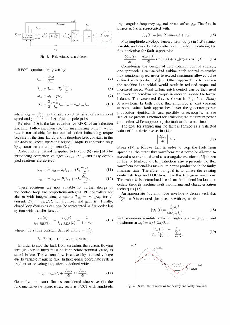
Fig. 4. Field-oriented control loop.
RFOC equations are given by:
imr =ψrdLm
, (7)
isd = imr + Trdimrdt
, (8)
ωsl = ωe − pωg, (9)
Tg =3
2pL2m
Lrimrisq = kmimrisq, (10)
where ωsl =isq
Trimris the slip speed, ωg is rotor mechanical
speed and p is the number of stator pole pairs.Relation (10) is the key equation for RFOC of an induction
machine. Following from (8), the magnetizing current vectorimr is not suitable for fast control action influencing torquebecause of the time lag Tr and is therefore kept constant in thesub-nominal speed operating region. Torque is controlled onlyby q stator current component (isq).
A decoupling method is applied to (5) and (6) (see [14]) byintroducing correction voltages ∆usd, ∆usq and fully decou-pled relations are derived:
usd + ∆usd = ksisd + σLsdisddt
, (11)
usq + ∆usq = Rsisq + σLsdisqdt
. (12)
These equations are now suitable for further design ofthe control loop and proportional-integral (PI) controllers arechosen with integral time constants TId = σLs/ks for d-current, TIq = σLs/Rs for q-current and gain Kr. Finally,closed loop dynamics can now be represented as first-order lagsystem with transfer function:
isd(s)
isd REF (s)=
isq(s)
isq REF (s)=
1
1 + τs, (13)
where τ is a time constant defined with τ = σLs
Kr.
V. FAULT-TOLERANT CONTROL
In order to stop the fault from spreading the current flowingthrough shorted turns must be kept below nominal value, asstated before. The current flow is caused by induced voltagedue to variable magnetic flux. In three-phase coordinate system(a, b, c) stator voltage equation is defined with:
usx = isxRs +dψsxdt≈ dψsx
dt. (14)
Generally, the stator flux is considered sine-wave (in thefundamental-wave approaches, such as FOC) with amplitude
|ψs|, angular frequency ωe and phase offset ϕx. The flux inphases a, b, c is represented with:
ψsx(t) = |ψs|(t) sin(ωet+ ϕx). (15)
Flux amplitude envelope denoted with |ψs|(t) in (15) is time-variable and must be taken into account when calculating theflux derivative for fault suppression:
dψsx(t)
dt=d|ψs|(t)dt
sin(ωet) + |ψs|(t)ωe cos(ωet). (16)
Considering the design of fault-tolerant control strategy,one approach is to use wind turbine pitch control to restrictflux rotational speed never to exceed maximum allowed valuedefined with product |ψs|ωe. Other approach is to weakenthe machine flux, which would result in reduced torque andincreased speed. Wind turbine pitch control can be then usedto lower the aerodynamic torque in order to impose the torquebalance. The weakened flux is shown in Fig. 5 as FaultyA waveform. In both cases, flux amplitude is kept constantat some value. Both approaches lower the generator powerproduction significantly and possibly unnecessarily. In thesequel we present a method for achieving the maximum powerproduction while suppressing the fault at the same time.
The goal for suppressing the fault is formed as a restrictedvalue of flux derivative as in (14):∣∣∣∣dψsxdt
∣∣∣∣ ≤ k. (17)
From (17) it follows that in order to stop the fault fromspreading, the stator flux waveform must never be allowed toexceed a restriction shaped as a triangular waveform |kt| shownin Fig. 5 (dash-dot). The restriction also represents the fluxwaveform that enables maximum power production in the faultymachine state. Therefore, our goal is to utilize the existingcontrol strategy and FOC to achieve that triangular waveform.The value k is determined based on fault identification pro-cedure through machine fault monitoring and characterizationtechniques [15].
An appropriate flux amplitude envelope is chosen such that∣∣∣dψsx
dt
∣∣∣ = k is ensured (for phase a with ϕa = 0):
|ψs|(t) =kωeωet
sin(ωet), (18)
with minimum absolute value at angles ωet = 0, π, ..., andmaximum at ωet = π/2, 3π/2...:
|ψs|(0) = kωe,
|ψs|(π2
)= k
ωe
π2 .
(19)
Healthy
Faulty A
Faulty B
ωet
ψsa
π
Fig. 5. Stator flux waveforms for healthy and faulty machine.

With modulated amplitude (18) the flux waveform from (15)obtains the form:
ψsa(t) = kt, t ∈ [− π2ωe
, π2ωe
]
ψsa(t) = −kt+ kπ, t ∈ [ π2ωe
, 3π2ωe
](20)
Transformed to the (d, q) and RFOC domain, stator fluxlinkage is defined with:
ψsd = σLsisd + Lm
Lrψrd,
ψsq = σLsisq,(21)
and relation |ψs| =√ψ2sd + ψ2
sq holds.Changing the ψrd is very slow due to large rotor time-lag Tr,
so we choose to manipulate the flux ψsx only through machinefast dynamics (13). Proper values of current components isdand isq are chosen to achieve the triangular form in Fig. 5.With this approach, minimum and maximum achievable fluxesare for the case when isq is set to zero and isd to rated valueof machine stator currents amplitude ∓|isn|:
ψs min,max = ∓σLs|isn|+LmLr
ψrd. (22)
However, desired machine torque and corresponding isq mustalso be included into consideration. Due to saturation, themaximum flux is also restricted with the rated value of statorflux. The value of ψrd is considered constant during themanipulation of stator flux. In practice it is influenced bychanging the isd current and it slowly fluctuates around meanvalue of the chosen ψrd.
If parameter k from the fault condition (17) is too large orchosen ψrd value limits the freedom for desired fast dynamics,desired amplitude scope shown in Fig. 6 with peak values(19) is not achievable. Therefore the minimum value is setto ψs min and when the amplitude envelope |ψs|(t) reachesvalue of ψs max (at time instant tm) it is fixed to that value.Stator flux takes the form presented as Faulty B in Fig. 5.The amplitude envelope is shown in Fig. 6 with dashed linerepresenting the case when triangular waveform is achievableand full line for the case of Faulty B waveform. The time instanttm can be obtained from condition:
ktm = ψs max sin(ωetm). (23)
Considering (16), influence of the static part|ψs|(t)ωe cos(ωet) of equation is examined. In the sequel weconsider the dynamic part d|ψs|(t)
dt sin(ωet). Derivative of fluxamplitude envelope (18) from Fig. 6 is:
d|ψs|(t)d(ωet)
=k
ωe
sin(ωet)− ωet cos(ωet)
sin2(ωet). (24)
The flux amplitude derivative reaches its maximum valueof k
ωeat time instant t = π
2ωe. For values of ωe that require
application of fault-tolerant algorithm the dynamic part hasmuch less influence (up to several hundred times) on fluxderivative than the static part.
Fastest achievable transient of currents is determined withinverter limitation. Considering the worst case scenario, highestoutputs from currents PI controllers described in previoussection are attained at the beginning of the transient with values
ωet
|ψs|(t)
ψs_max
ψs_min
kωeπ2
π2
ωetm π
Fig. 6. Flux amplitude from (18) chosen to achieve∣∣∣ dψsdt
∣∣∣ ≤ k.
of usd,q + ∆usd,q = Kr(isd,q REF − isd,q). Respecting themaximum available voltage supplied to one phase Umax thatarise from maximum voltage Udc of the dc-link (see Fig. 4)and corresponding Usd max and Usq max voltages, maximumvalues of (isd,q REF − isd,q) can be roughly calculated as:
isd REF − isd = 1Kr
(|Usd max|+ 1
Tr
L2mLr
imr + ωeσLsisq
), (25)
isq REF − isq = 1Kr
(|Usq max| − ωe Lm
2
Lrimr − ωeσLsisd
). (26)
The flux derivative can be expressed as:
d|ψs|(t)dt
=d|ψs|(t)disd
· disddt
+d|ψs|(t)disq
· disqdt
. (27)
By including the flux derivative with respect to currents from(21) and currents time derivatives that arise from (13), (25) and(26)
(disd,qdt =
isd,q REF−isd,qτ
), the maximum possible d|ψs|(t)
dt
by far exceeds the needed condition of kωe
(about hundred timesfor the worst case in our simulations).
Therefore by disregarding the dynamical part in (16), avail-able generator electrical speed is chosen from product |ψs|ωe:
ωe ≤ αk
ψs min, (28)
where α = 0.9 is a redundancy factor that ensures possibilityof manipulation with isd and isq currents. The factor placesthe minimum value of |ψs|(t) little above ψs min as shown inFig. 6.
Using the described method, an exemplary graph of availablespeed-torque points under machine fault is shown in Fig. 7.Normal operation of the healthy generator is bounded with ratedmachine torque Tgn and rated speed ωgn and pitch control isresponsible to keep the operating point between boundaries.The curve denoted with Optimum power represents optimaloperating points of wind turbine at which the power factorcoefficient Cp and power production is at maximum value.
For the case of diagnosed fault, dashed area denotes allavailable generator torque values that can be achieved forcertain generator speed. Below speed ω∗g generator is operatingin the safety region and no fault-tolerant control is needed.It follows that up to the speed ωg1 it is possible to controlthe wind turbine in the faulty case without sacrificing powerproduction. However, from that speed onwards it is necessaryto use blades pitching in order to limit the aerodynamic torqueand to keep the power production below optimal in order tosuppress the fault from spreading. The speed control loop is

0 10 20 300
50
100
150
200
250
Tgn
ωg1ωg*
Speed (rpm)
Ge
ne
rato
r to
rqu
e (
kNm
)
Optimum power
ωgn
Fig. 7. Available torque-speed generator operating points under fault condition(shaded area).
modified such that instead of reference ωgn the reference ωg1is selected. Interventions in classical wind turbine control thatensure fault-tolerant control are given in Fig. 8.
Desired generator torque reference dictated by the windturbine torque control loop determines adequate value of ωe andimr (or ψrd) used to achieve correct ψs min and ψs max. Propercurrent references isd REF and isq REF are then calculated toobtain desired stator flux wave. The algorithm is given in thesequel:
Algorithm 1 Fault-tolerant control for stator fault1. Choose correct ψs max as a lower value between rated fluxψsn and (19) with diagnosed fault condition k and currentflux rotational speed ωe;
2. Find angle ωetm from (23) and calculate approximate meanvalue of stator flux ψs mean = 1
n
∑ni=1 ψsi with ψs min
from (19) and ψs max;3. Obtain imr mean from ψs mean; isq mean from desired
torque Tgref , imr mean and (10) respecting the maximumallowed slip value (9); isd max from ψmax and (21);
4. If isd max >√i2sn − i2sq mean decrease ψs max by a small
value ε and go back to step 2., iteratively;5. Calculate isd REF from (18) and (21) with imr mean andisq mean, set isq REF = isq mean;
6. Compute ωg1 as a speed coordinate of the intersection pointof Tav(ωg) and of the normal wind turbine torque controllercharacteristics, compute ω1 = ωg1/ns where ns is thegearbox ratio. Set ωref = ω1.
Step 5. is executed at each discrete time step, while othersteps are executed once in every stator flux modulation period(Fig. 6) for less computational effort.
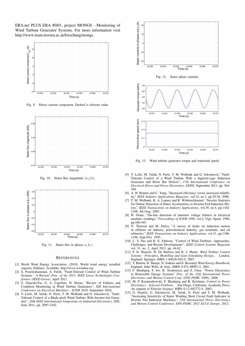
VI. SIMULATION RESULTS
This section provides simulation results for a 700 kWMATLAB/Simulink variable-speed variable-pitch wind turbinemodel with a two-pole 5.5 kW SCIG scaled to match the torqueand power of 700 kW machine.
TORQUEcontroller
GENERATOR & INVERTER
WIND
FAULT-TOLERANT control
ωref
ω
ω
β
Tg
WINDTURBINE
ω
Tgref'
βref PITCH servo& controller
SPEEDcontroller
ωg
+-
isd_REF
isq_REF
ωe
Fig. 8. Control system of wind turbine with fault-tolerant control strategy.
Generator parameters are: Ls = Lr = 0.112 H, Lm = 0.11H, Rs = 0.3304 Ω, Rr = 0.2334 Ω and PI controller gain isKr = 6. Turbine parameters are: CPmax = 0.4745, R = 25m, λopt = 7.4, ωn = 29 rpm, Ttn = 230.5 kNm with gearboxratio ns = 105.77. Stator flux rated value is ψsn = 0.625 Wband sample time is chosen Ts = 10−4 s. Moment of inertiaof wind turbine and generator, reduced to the generator side isJ = 72.11 kgm2.
In the sequel simulation results with diagnosed fault and∣∣∣dψsx
dt
∣∣∣ = k = 100 Wb/s are presented. The isq current ischosen as constant value in order to maintain the desired torque.Therefore stator flux is manipulated only by isd as presentedin Fig. 9.
Stator flux amplitude envelope from (18) is shown in Fig. 10and corresponding stator flux waveforms in phases a, b, c areshown in Fig. 11. Following from figures, the required restric-tion formed as described triangular waveform is satisfied inshorted phase (phase a). Phase currents calculated to achievedesired flux waveforms are shown in Fig. 12. Currents followa sinusoidal shape with deviations at peak values. With bettertracking performance of isd with respect to the reference valuein Fig. 9 or by compensation of the referent value with includedprediction procedure, more symmetric waveforms of flux, aswell as those of currents, in phases a, b, c can be achieved.
Fig. 13 shows that proposed fault-tolerant algorithm intro-duces torque oscillations in the system. This occurs due to rapidchanging of isd and its reflection on machine rotor flux ψrd.Proper modulation of isq current can overcome this problem.However, because of very large moment of inertia of the windturbine, torque oscillations have negligible influence on windturbine rotational speed.
VII. CONCLUSIONS
We introduced a fault-tolerant control strategy for variable-speed variable-pitch wind turbines. The focus is on a squirrel-cage generator with diagnosed short-circuit between turns of thesame phase. An extension of the conventional control structureis proposed that prevents the fault propagation and enablesfaulty wind turbine operation with reduced power. The powerdelivery under fault is deteriorated as less as possible comparedto healthy machine conditions.
ACKNOWLEDGEMENT
This work has been supported by the European Com-mission and the Republic of Croatia under grant FP7-SEE-
ERA.net PLUS ERA 80/01, project MONGS - Monitoring ofWind Turbine Generator Systems. For more information visithttp://www.ieam.tuwien.ac.at/forschung/mongs.
42.025 42.035 42.045 42.055 42.065 42.075−10
−5
0
5
10
15
Time (s)
Dire
ct c
urre
nt c
ompo
nent
i sd(A
)
Fig. 9. Direct current component. Dashed is referent value.
42.025 42.035 42.045 42.055 42.065 42.0750.44
0.48
0.52
0.56
Time (s)
Sta
tor
flux
mag
nitu
de (
Wb)
Fig. 10. Stator flux magnitude |ψs|(t).
42.025 42.035 42.045 42.055 42.065 42.075
−0.6
−0.4
−0.2
0
0.2
0.4
0.6
Time (s)
Sta
tor
flux
in p
hase
s a,
b,c
(Wb)
Fig. 11. Stator flux in phases a, b, c.
REFERENCES
[1] World Wind Energy Association. (2010). World wind energy installedcapacity [Online]. Available: http://www.wwindea.org
[2] S. Pourmohammad, A. Fekih, ”Fault-Tolerant Control of Wind TurbineSystems - A Review”,Proc. of the 2011. IEEE Green Technologies Con-ference (IEEE-Green), April 2011.
[3] Z. Daneshi-Far, G. A. Capolino, H. Henao, ”Review of Failures andCondition Monitoring in Wind Turbine Generators”, XIX InternationalConference on Electrical Machines - ICEM 2010, September 2010.
[4] V. Lesic, M. Vasak, N. Peric, T. M. Wolbank and G. Joksimovic, ”Fault-Tolerant Control of a Blade-pitch Wind Turbine With Inverter-fed Gener-ator”, 20th IEEE International Symposium on Industrial Electronics, ISIE,June 2011, pp. 2097-2102.
42.025 42.035 42.045 42.055 42.065 42.075
−20
−10
0
10
20
Time (s)
Sta
tor
curr
ents
in p
hase
s a,
b,c
(A)
Fig. 12. Stator phase currents.
42.025 42.035 42.045 42.055 42.065 42.075
102
103
104
105
106
Time (s)
Gen
erat
or to
rque
(kN
m)
42.025 42.035 42.045 42.055 42.065 42.075
21
21.1
21.2
21.3
Time (s)
Win
d tu
rbin
e sp
eed
(rp
m)
Fig. 13. Wind turbine generator torque and rotational speed.
[5] V. Lesic, M. Vasak, N. Peric, T. M. Wolbank and G. Joksimovic, ”Fault-Tolerant Control of a Wind Turbine With a Squirrel-cage InductionGenerator and Rotor Bar Defects”, 17th International Conference onElectrical Drives and Power Electronics, EDPE, September 2011, pp. 364-369.
[6] A. H. Bonnet and C. Yung, ”Increased efficiency versus increased reliabil-ity,” IEEE Industry Applications Magazine, vol.14, no.1, pp.29-36, 2008.
[7] T. M. Wolbank, K. A. Loparo and R. Wohrnschimmel, ”Inverter Statisticsfor Online Detection of Stator Asymmetries in Inverter-Fed Induction Mo-tors,” IEEE Transactions on Industry Applications, vol.39, no.4, pp.1102-1108, Jul./Aug. 2003.
[8] H. Oraee, ”On-line detection of interturn voltage failures in electricalmachine windings,” Proceedings of ICEM 1996, vol.2, Vigo, Spain, 1996,pp.440-445.
[9] O. Thorsen and M. Dalva, ”A survey of faults on induction motorsin offshore oil industry, petrochemical industry, gas terminals, and oilrefineries,” IEEE Transactions on Industry Applications, vol.31, pp.1186-1196, Sept./Oct. 1995.
[10] L. Y. Pao and K. E. Johnson, ”Control of Wind Turbines: Approaches,Challenges, and Recent Developments”, IEEE Control Systems Magazinevol. 31, no. 2, April 2011, pp. 44-62.
[11] F. D. Bianchi, H. De Battista and R. J. Mantz, Wind Turbine ControlSystems - Principles, Modelling and Gain Scheduling Design., London,England: Springer, ISBN 1-84628-492-9, 2007.
[12] T. Burton, D. Sharpe, N. Jenkins and E. Bossanyi Wind Energy Handbook,England: John Wiley & Sons, ISBN 0-471-48997-2, 2001.
[13] F. Blaabjerg, F. Iov, R. Teodorescu and Z. Chen. ”Power Electronicsin Renewable Energy Systems” Proc. of the 12th International PowerElectronics and Motion Control Conf. (EPE-PEMC 2006), 2006.
[14] M. P. Kazmierkowski, F. Blaabjerg and R. Krishnan, Control in PowerElectronics - Selected Problems, San Diego, California: Academic Press,An imprint of Elsevier Science, ISBN 0-12-402772-5, 2002.
[15] G. Stojicic, G. Joksimovic, M. Vasak, N. Peric and T. M. Wolbank,”Increasing Sensitivity of Stator Winding Short Circuit Fault Indicator inInverter Fed Induction Machines”, 15th International Power Electronicsand Motion Control Conference, EPE-PEMC 2012 ECCE Europe, 2012.